BHT-407-MM-9 76-00-00 16 FEB 2012 Rev. 34 Page 1 ECCN EAR99 TABLE OF CONTENTS Paragraph Chapter/Section Page Number Title Number Number CHAPTER 76 — ENGINE CONTROLS GENERAL 76-1 Full Authority Digital Electronic Control (FADEC) .......................... 76-00-00 5 76-2 FADEC System Acronyms........................................................ 76-00-00 5 76-3 FADEC Control Features .......................................................... 76-00-00 5 76-4 FADEC System Components ................................................... 76-00-00 6 76-5 Power-up Mode and Built In Test ............................................. 76-00-00 7 FADEC CONTROL SYSTEM — OPERATION 76-6 Start In AUTO Mode — Description ............................................... 76-00-00 11 76-7 Start in AUTO Mode — Alternate Start ..................................... 76-00-00 13 76-8 Start In MANUAL Mode — Description .......................................... 76-00-00 13 76-9 FADEC Manual Check — Description ........................................... 76-00-00 14 76-10 In-flight — Auto Mode Operation ................................................... 76-00-00 14 76-11 NDOT Control ........................................................................... 76-00-00 15 76-12 Gas Generator (N G ) Governor .................................................. 76-00-00 15 76-13 Power Turbine (N P ) Governor .................................................. 76-00-00 15 76-14 Engine Auto Relight ....................................................................... 76-00-00 15 76-15 AUTO Mode — Auto Relight (N G Above 50%) ......................... 76-00-00 15 76-16 AUTO Mode — Pilot Assisted In-flight Restart (N G Between 9.5 and 50%) ............................................................................ 76-00-00 15 76-17 Manual Mode — Relight ................................................................ 76-00-00 16 76-18 Engine Overspeed and Protection — Description ......................... 76-00-00 16 76-19 N P Overspeed ................................................................................ 76-00-00 19 76-20 Power-up Functional Check...................................................... 76-00-00 20 76-21 Continuous Functional Check ................................................... 76-00-00 20 76-22 Overspeed System Failure Annunciation ................................. 76-00-00 20 76-23 Overspeed System Shutdown Check ....................................... 76-00-00 20 76-24 N G Overspeed................................................................................ 76-00-00 20 76-25 Engine Shutdown ........................................................................... 76-00-00 21 76-26 HMU Manual Piston Parking Procedure ................................... 76-00-00 21 76-27 FADEC System Faults .............................................................. 76-00-00 22 76-28 Category 1 — FADEC Failure .................................................. 76-00-00 22 76-29 Auto to MANUAL Mode Transition............................................ 76-00-00 25 76-30 Category 2 — FADEC Degraded.............................................. 76-00-00 33 76-31 Category 3 — FADEC Fault ..................................................... 76-00-00 33 76-32 Category 4 — Restart Fault ...................................................... 76-00-00 33 76-33 Category 5 — Maintenance Advisory, FADEC System Faults — Engine Shutdown ................................................................. 76-00-00 33 76-34 FADEC Faults/Exceedances — Recording Procedure .................. 76-00-00 34 76-35 FADEC Faults/Exceedances — Clearing Procedure ..................... 76-00-00 34 76-36 Recorded Exceedances/Conversion Factors................................. 76-00-00 34 76-37 Downloading N G , MGT, and Torque (Q) Exceedances Recorded by FADEC (ECU) .......................................................... 76-00-00 36

407-MM-CH76
Dec 01, 2015
Bell 407 Maintenance Manual Chapter 76
Welcome message from author
This document is posted to help you gain knowledge. Please leave a comment to let me know what you think about it! Share it to your friends and learn new things together.
Transcript

BHT-407-MM-9
76-00-0016 FEB 2012 Rev. 34 Page 1ECCN EAR99
TABLE OF CONTENTS
Paragraph Chapter/Section Page Number Title Number Number
CHAPTER 76 — ENGINE CONTROLS
GENERAL
76-1 Full Authority Digital Electronic Control (FADEC) .......................... 76-00-00 576-2 FADEC System Acronyms........................................................ 76-00-00 576-3 FADEC Control Features.......................................................... 76-00-00 576-4 FADEC System Components ................................................... 76-00-00 676-5 Power-up Mode and Built In Test ............................................. 76-00-00 7
FADEC CONTROL SYSTEM — OPERATION
76-6 Start In AUTO Mode — Description............................................... 76-00-00 1176-7 Start in AUTO Mode — Alternate Start..................................... 76-00-00 1376-8 Start In MANUAL Mode — Description.......................................... 76-00-00 1376-9 FADEC Manual Check — Description ........................................... 76-00-00 1476-10 In-flight — Auto Mode Operation ................................................... 76-00-00 1476-11 NDOT Control ........................................................................... 76-00-00 1576-12 Gas Generator (NG) Governor.................................................. 76-00-00 1576-13 Power Turbine (NP) Governor .................................................. 76-00-00 1576-14 Engine Auto Relight ....................................................................... 76-00-00 1576-15 AUTO Mode — Auto Relight (NG Above 50%) ......................... 76-00-00 1576-16 AUTO Mode — Pilot Assisted In-flight Restart (NG Between
9.5 and 50%) ............................................................................ 76-00-00 1576-17 Manual Mode — Relight ................................................................ 76-00-00 1676-18 Engine Overspeed and Protection — Description ......................... 76-00-00 1676-19 NP Overspeed................................................................................ 76-00-00 1976-20 Power-up Functional Check...................................................... 76-00-00 2076-21 Continuous Functional Check................................................... 76-00-00 2076-22 Overspeed System Failure Annunciation ................................. 76-00-00 2076-23 Overspeed System Shutdown Check ....................................... 76-00-00 2076-24 NG Overspeed................................................................................ 76-00-00 2076-25 Engine Shutdown........................................................................... 76-00-00 2176-26 HMU Manual Piston Parking Procedure ................................... 76-00-00 2176-27 FADEC System Faults.............................................................. 76-00-00 2276-28 Category 1 — FADEC Failure .................................................. 76-00-00 2276-29 Auto to MANUAL Mode Transition............................................ 76-00-00 2576-30 Category 2 — FADEC Degraded.............................................. 76-00-00 3376-31 Category 3 — FADEC Fault ..................................................... 76-00-00 3376-32 Category 4 — Restart Fault ...................................................... 76-00-00 3376-33 Category 5 — Maintenance Advisory, FADEC System Faults
— Engine Shutdown ................................................................. 76-00-00 3376-34 FADEC Faults/Exceedances — Recording Procedure.................. 76-00-00 3476-35 FADEC Faults/Exceedances — Clearing Procedure..................... 76-00-00 3476-36 Recorded Exceedances/Conversion Factors................................. 76-00-00 3476-37 Downloading NG, MGT, and Torque (Q) Exceedances
Recorded by FADEC (ECU) .......................................................... 76-00-00 36

BHT-407-MM-9
76-00-00Page 2 Rev. 34 16 FEB 2012 ECCN EAR99
TABLE OF CONTENTS (CONT)
Paragraph Chapter/Section Page Number Title Number Number
76-38 Determination of Faults/Exceedances and RequiredTroubleshooting Steps ................................................................... 76-00-00 37
76-39 Maintenance Mode — Procedure for Viewing FADEC FaultCodes Using Caution Panel Flashing Display (S/N 53000Through 54299) ............................................................................. 76-00-00 39
76-40 FADEC Fault Codes — Procedure to Determine Last EngineRun Faults From “Current” Faults .................................................. 76-00-00 47
76-41 Check Run Procedure.................................................................... 76-00-00 4776-42 FADEC Download Intervals ........................................................... 76-00-00 4776-43 Engine Start — Troubleshooting.................................................... 76-00-00 48
HYDROMECHANICAL ENGINE CONTROLS
76-44 Hydromechanical Unit (HMU) ........................................................ 76-00-00 5176-45 Hydromechanical Unit (HMU) — Removal ............................... 76-00-00 5176-46 Hydromechanical Unit (HMU) — Installation ............................ 76-00-00 51
MECHANICAL ENGINE CONTROLS
76-47 Throttle/Fly Detent Rigging Procedure........................................... 76-00-00 5776-48 Throttle/Fly Detent Friction Check ................................................. 76-00-00 6176-49 Throttle/Fly Detent Friction Adjustment.......................................... 76-00-00 6176-50 Throttle Control Cable.................................................................... 76-00-00 6476-51 Throttle Control Cable — Removal........................................... 76-00-00 6476-52 Throttle Control Cable — Inspection......................................... 76-00-00 6476-53 Throttle Control Cable — Installation........................................ 76-00-00 70
ELECTRICAL ENGINE CONTROLS
76-54 Electrical Engine Controls — General ........................................... 76-00-00 7376-54A Electrical Engine Controls — Application of Contact
Enhancer........................................................................... 76-00-00 7376-55 Electronic Control Unit (ECU) ................................................... 76-00-00 7376-56 Electronic Control Unit (ECU) — Removal S/N 53000
Through 53749 Pre TB 407-07-75 .................................... 76-00-00 7376-57 Electronic Control Unit (ECU) — Removal S/N 53000
Through 53749 Post TB 407-07-75 and S/N 53750 andSubsequent (Including 407GX)......................................... 76-00-00 74
76-58 Electronic Control Unit (ECU) — Inspection ..................... 76-00-00 7976-59 Electronic Control Unit (ECU) — Installation S/N 53000
Through 53749 Pre TB 407-07-75 .................................... 76-00-00 7976-60 Electronic Control Unit (ECU) — Installation S/N 53000
Through 53749 Post TB 407-07-75 and 53750 andSubsequent (Including 407GX)......................................... 76-00-00 80
76-61 Collective Pitch Transducer (CPT) ........................................... 76-00-00 8176-62 Collective Pitch Transducer (CPT) — Removal................ 76-00-00 8176-63 Collective Pitch Transducer (CPT) — Inspection.............. 76-00-00 8576-64 Collective Pitch Transducer (CPT) — Installation/Rigging 76-00-00 8576-65 Collective Pitch Transducer (CPT) — Functional Test ..... 76-00-00 86

BHT-407-MM-9
76-00-0016 FEB 2012 Rev. 34 Page 3ECCN EAR99
TABLE OF CONTENTS (CONT)
Paragraph Chapter/Section Page Number Title Number Number
76-66 Compressor Inlet Temperature (CIT) Sensor ........................... 76-00-00 8776-67 Compressor Inlet Temperature (CIT) Sensor
— Removal ....................................................................... 76-00-00 8776-68 Compressor Inlet Temperature (CIT) Sensor
— Inspection ..................................................................... 76-00-00 8776-69 Compressor Inlet Temperature (CIT) Sensor
— Installation .................................................................... 76-00-00 8976-70 Compressor Inlet Temperature (CIT) Sensor
— Functional Test............................................................. 76-00-00 89
FIGURES
Figure Page Number Title Number
76-1 FADEC Control System Schematic .................................................................... 876-2 HMU Schematic .................................................................................................. 976-3 Engine Overspeed Light and ECU NP Recording Activation Table for
FADEC Software Version 5.202 ......................................................................... 1776-4 Example of Engine History Data — Maintenance............................................... 1876-5 Instrument Panel — FADEC System Switches, Caution/Warning Panel ........... 2376-6 Auto to Manual Transition at Low Fuel Flow....................................................... 2676-7 Auto to Manual Transition at Intermediate Fuel Flow ......................................... 2876-8 Auto to Manual Transition at High Fuel Flow ...................................................... 3076-9 FADEC/ECU Maintenance Button and FADEC/ECU Maintenance Terminal
Connector ........................................................................................................... 4076-10 HMU — Removal/Installation.............................................................................. 5276-11 Engine Control Rigging ....................................................................................... 5376-12 Rigging Fly Detent .............................................................................................. 5976-13 Collective Throttle Friction .................................................................................. 6376-14 Throttle Control Cable......................................................................................... 6576-15 Electronic Control Unit (ECU) — Removal/Installation S/N 53000 Through
53749 Pre TB 407-07-75 .................................................................................... 7576-16 Electronic Control Unit (ECU) — Removal/Installation S/N 53000 Through
53749 Post TB 407-07-75 and S/N 53750 and Subsequent............................... 7776-17 Collective Pitch Transducer (CPT) — Removal/Installation................................ 8276-18 Compressor Inlet Temperature (CIT) Sensor — Removal/Installation ............... 88
TABLES
Table Page Number Title Number
76-1 Time to Power Change — (DRTM)..................................................................... 3376-2 250-C47B FADEC Software Version 5.202 Fault Code Display......................... 41

BHT-407-MM-9
76-00-00Page 4 Rev. 33 23 SEP 2011 ECCN EAR99
TABLES (CONT)
Table Page Number Title Number
76-3 250-C47B FADEC Software Versions 5.356 and 5.358(Reversionary Governor) Fault Code Display ..................................................... 44
76-4 Throttle Rigging Parameters ............................................................................... 61

BHT-407-MM-9
76-00-0016 FEB 2012 Rev. 34 Page 5ECCN EAR99
GENERAL
76-1. FULL AUTHORITY DIGITALELECTRONIC CONTROL (FADEC)
This chapter contains information pertaining to theFADEC engine control system and its associatedairframe inputs. Electronic Control Unit (ECU)Software Versions 5.202 and 5.356 or 5.358(Reversionary Governor) with Direct Reversion toManual (DRTM) are addressed.
For additional information on the FADEC system, referto the Rolls-Royce 250-C47B Operation andMaintenance Manual, Publication CSP 21001.Additionally, reference to Rolls-Royce CommercialService Letter CSL-6069 will provide general FADECsystem maintenance guidelines.
76-2. FADEC SYSTEM ACRONYMS
• Compressor Inlet Temperature (CIT)
• Combined Engine Filter Assembly (CEFA)
• Collective Pitch (CP)
• Collective Pitch Transducer (CPT)
• Caution/Warning/Advisory Panel (CWAP)
• Direct Reversion To Manual System (DRTM)
• Electronic Control Unit (ECU)
• Engine Monitoring System (EMS)
• Full Authority Digital Electronic Control(FADEC)
• Volatile Memory – Data Lost When Power isRemoved
• Line Replaceable Unit (LRU)
• Non-volatile Memory – Data Not Lost WhenPower is Removed
• Hydromechanical Unit (HMU)
• Measured Gas Temperature (MGT)
• Gas Generator Speed (NG)
• Power Turbine Speed (NP)
• Rate of Change of NG Speed (NDOT)
• Main Rotor Speed (NR)
• Power Lever Angle (PLA) – Controlled byThrottle Position
• Permanent Magnet Alternator (PMA)
• Resistance Temperature Device (RTD)
• Torque Meter Oil Pressure (TMOP)
• Fuel Flow (Wf)
76-3. FADEC CONTROL FEATURES
The engine control and monitoring systems providethe following features:
1. Fault Detection – The ECU monitors the FADECsystem for faults and makes appropriateaccommodation to continue operation. When theengine is operating, fault codes are stored inside theECU in non-volatile memory.
2. Automatic Start – The ECU provides forautomatic control of fuel flow during engine starts tocontrol the rate of acceleration and limit engine starttemperature. The control provides a hot start abortfeature that cuts fuel flow off to prevent anovertemperature start.
3. NDOT Control System – The engine control lawis based on a Gas Generator rate of acceleration(NDOT) system that maximizes engine performancewhile maintaining safe engine operation.
4. Electronically Controlled Gas Generator (NG)Governor – Allows engine power control andmodulation, from shutoff to maximum power, via thethrottle twist grip.
5. Electronically Controlled Power Turbine (NP)Governor – Provides constant power turbine speedgoverning.
6. Auto Relight – The ECU detects engine flameoutand initiates an automatic engine relight sequence.

BHT-407-MM-9
76-00-00Page 6 Rev. 34 16 FEB 2012 ECCN EAR99
7. Overspeed System – The ECU protects againstGas Generator (NG) (FADEC Software Version 5.202)and Power Turbine (NP) overspeed. The ECUprovides a power-up self-test and a pilot initiated testat engine shutdown to verify proper operation.
NOTE
407 helicopters S/N 53000 through 54299utilize a caution/warning/advisory panel forannunciations while 407GX helicoptersS/N 54300 and subsequent utilize a CrewAlerting System (CAS) to displayannunciations (Chapter 96).
8. Failure Annunciation – The operational status ofthe engine control system is automatically andcontinually monitored by the ECU. Should a failure bedetected, it will be annunciated to the pilot. When acontrol system fault occurs that prevents continuedoperation of the AUTO mode control, the FADEC FAILwill be annunciated. The FADEC DEGRADED will beannunciated when a fault has occurred that may affectengine performance, or if maintenance action isrequired following shutdown. The FADEC FAULT willbe annunciated when a fault has occurred that doesnot affect engine performance, but may affect anoperating feature such as engine limiting. TheRESTART FAULT will be annunciated when a fault isdetected that may affect the ability of the engine tostart in the AUTO mode. This failure information will berecorded by the ECU.
9. Engine Condition Monitoring – The ECU providesan Engine Monitoring System (EMS) to record and logFADEC system faults and engine overspeed limitexceedances.
10. Exceedance Protection – Automatic protectionfunctions accomplished by the FADEC include MGTtemperature protection, NG speed protection, and NPspeed protection. In the Model 407, the FADECprovides engine MGT limiting at the engine maximumtransient (1661°F (905°C)).
In regards to MGT limiting, the FADEC systeminterfaces to the MGT harness to measure enginetemperature. When the engine is approaching itsmaximum transient temperature limit, the FADECreduces fuel flow to prevent limit exceedance (1661°F(905°C)). A smooth, controlled transition betweengoverning and temperature limiting is accomplished bythe FADEC.
11. Surge Detection and Recovery – The FADECdetects engine surge by comparing the rate of changeof NG speed to a predetermined boundary rate. If theboundary is exceeded and MGT is increasing, thesurge will be detected and recorded by the internalECU Engine Monitor System (EMS). The surge will berecorded in the ECU's memory relative to the NGspeed at which it occurred. Without pilot action, theFADEC will reduce fuel flow during the surge andreduce the maximum acceleration schedule againstthe current acceleration in order to recover from thesurge. The FADEC will then lower the accelerationschedule at the range of NG where the surge occurredto avoid subsequent surge. The acceleration scheduleis reset to the original schedule at the next FADECpower-up.
12. MANUAL Mode – In MANUAL mode, the pilot'sPLA input is tied hydromechanically to the fuel flowmetering valve in the HMU. MANUAL mode isengaged by de-energizing the auto/manual solenoid inthe HMU. This allows the pilot to vary fuel flow to theengine by moving the PLA, via the throttle twist grip.This MANUAL mode fuel flow is altitude compensatedto allow a consistent PLA/horsepower relationshipversus altitude. At 100% throttle travel, the MANUALmode will provide sea level rated takeoff power at sealevel. The fuel flow slew rate is mechanically limited toavoid blowout and to provide proper responsivenessfor helicopter operation.
13. Maintenance Mode – The ECU provides amaintenance mode function. This function is onlyoperational on the ground and is a guide totroubleshooting. On 407 helicopters S/N 53000through 54299, this function identifies, by a series offlashing lights, the suspect LRU when a fault in theFADEC system has been indicated. The maintenancemode is also used to identify recorded exceedances.
On 407GX helicopters S/N 54300 and subsequent,fault codes and exceedances can be viewed directlyfrom the Bell Maintenance Pages (Chapter 95) on theMulti-Function Display (MFD).
76-4. FADEC SYSTEM COMPONENTS
The Model 407 power plant is made up of aRolls-Royce 250-C47B engine with an electroniccontrol system. The control system is based upon asingle channel Full Authority Digital Electronic Control(FADEC) that controls, monitors, and limits engine

BHT-407-MM-9
76-00-0016 FEB 2012 Rev. 34 Page 7ECCN EAR99
power while maintaining helicopter rotor speed. Thereis also a MANUAL mode hydromechanical backup.
The FADEC system has two main components. Theairframe mounted Electronic Control Unit (ECU) andthe engine mounted Hydromechanical Unit (HMU).
The ECU monitors numerous internal and externalinputs to modulate fuel flow and therefore controlengine speed, acceleration rate, temperature, andother engine parameters. The ECU provides inputs tothe HMU to modulate fuel flow based on thecontinuous monitoring of the following: Measured GasTemperature (MGT), Gas Generator speed (NG),Power Turbine speed (NP), Main Rotor speed (NR),Engine Torque Meter Oil Pressure (TMOP), CollectivePitch (CP) and rate, Compressor Inlet Temperature(CIT), Ambient Pressure (P1), and Power Lever Angle(PLA)/throttle position (Figure 76-1).
On helicopters with FADEC Software Version 5.356 or5.358 installed, the engine uses a digital electroniccontrol system based on two electronic governorscalled primary channel and reversionary governor. Theprimary channel is a full-authority digital electroniccontrol (FADEC) that controls, monitors, and limitsengine power while maintaining helicopter rotor speed.The reversionary governor can automatically takecontrol over the engine in the event of a primarychannel failure. The reversionary governor uses alimited set of inputs and provides basic electronicgoverning.
To be more specific, the 5.356 and 5.358 FADECReversionary (backup) Governor consists primarily ofa backup channel that is contained in the ECU and isisolated from the primary governor by a firewall forEMI. It provides basic power turbine speed governingin the event of a hard fault occurring in the primarygovernor. Failure of the FADEC into reversionarygovernor mode is indicated by the illumination of thefollowing three lights: FADEC FAULT, FADECDEGRADED, and RESTART FAULT. This type offailure causes a degradation in performance and cancause NR droop or NR lag. Operations should becontinued in AUTO mode and helicopter is to be flownsmoothly and non-aggressively. Applicablemaintenance action will be required prior to next flight(paragraph 76-38).
The engine gearbox mounted Hydromechanical Unit(HMU) consists of an engine driven fuel pump
assembly and a fuel metering unit assembly combinedinto one unit (Figure 76-2).
The fuel pump assembly of the HMU consists of a sidechannel liquid ring boost stage and a gear main stage.The fuel pump assembly contains a high pressurerelief valve.
The fuel metering unit assembly of the HMU consistsof a stepper motor controlled flat plate metering valve,a metering head regulator valve, a windmill bypassvalve, a minimum flow bypass valve, a metering headaltitude compensation valve, a pressurizing andshutoff valve, an overspeed solenoid valve, a hot startfuel solenoid valve, an auto/manual changeoversolenoid valve, and a manual Wf/P1 servomechanism.
Pump discharge fuel flow passes through the meteringvalve and, in parallel, through the minimum flow pathand out to the fuel nozzle. Excess pump discharge fuelflow is returned back to the pump gear stage inlet bythe metering head regulator valve. In the AUTO mode,the metering valve flow area is set by stepper motorposition. In the MANUAL mode, the metering valveflow area is set as a function of PLA/throttle position.In either mode, engine shutdown is accomplished byretarding the PLA/throttle to the cutoff position. Thisaction causes the windmill bypass valve to dumpmetering valve discharge pressures which, in turn,causes the pressurizing and shutoff valve to close.Prior to exiting the HMU, fuel must pass through theoverspeed solenoid valve. When energized, theoverspeed solenoid valve closes, causing fuel flow togo to a minimum flow (sub-idle) condition.
76-5. POWER-UP MODE AND BUILT IN TEST
The FADEC system incorporates logic and circuitry toperform self-diagnostics. In general, sensors arechecked for continuity, rate, and proper range.Discrete inputs are checked for continuity and outputdrivers are monitored for current demand to sensefailed actuators and open or shorted circuits. AFADEC power-up self-test exercises outputdrivers and actuators to ensure systemfunctionality and readiness. As applicable to 407GXhelicopters S/N 54300 and subsequent, if a FADEClamp test failure is identified during the power-upself-test (or subsequently during flight), a FADECMTCE Crew Alerting System (CAS) advisory messagewill be displayed indicating that maintenance action isrequired.

BHT-407-MM-9
76-00-00Page 8 Rev. 33 23 SEP 2011 ECCN EAR99
Figure 76-1. FADEC Control System Schematic
OIL PRESSURETORQUE METER
(TMOP)SPEED (N )POWER TURBINE
SPEED (N )GAS GENERATOR
COMPRESSOR
TEMPERATURE
(CIT)
PERMANENT MAGNET
N
N
HYDRO-MECHANICAL
FUEL NOZZLE
FUEL IN
LEVERPOWER
ENGINEAIRFRAME
THROTTLE(PLA) LINKAGE
FUEL
UNIT (ECU)
ELECTRONIC
AMBIENTPRESSURE(P1)
ISOLATORSVIBRATION
AUTO RELIGHTIGNITER RELAY
STARTER RELAYLATCHING
MAIN ROTOR
+28 VDC BATTERY/
FADEC/ECU MTCE
TERMINAL
COCKPIT TYPICAL
N
N /N
MGT
OVERSPEED
ON
MANUAL
PITCH (CP)
AUTOFUEL
FILTER
OUT
UNIT(HMU)
THROTTLEPOWER LEVERANGLE (PLA)
-FADEC FAIL-FADEC MANUAL-FADEC DEGRADED-FADEC FAULT-RESTART FAULT-ENGINE OVSPD-ENGINE OUT-AUTO RELIGHT
CAUTIONPANEL LIGHTS/CAS
AND RATE
COLLECTIVE
FADEC MODE SWITCH
TEST SWITCH
120
60
60
120
(MECHANICAL LINKAGE)
CONNECTOR)
PORT (MTCE
AIRFRAME POWER
SPEED (N )
CONTROL
(PMA)
ALTERNATOR
INLET (MGT)MEASURED
GASTEMPERATURE
G
P R
R
P
G
G
P
MESSAGES (407GX)
407MM_76_0001_c03+

BHT-407-MM-9
76-00-0016 FEB 2012 Rev. 34 Page 9ECCN EAR99
Figure 76-2. HMU Schematic407MM_76_0002
AUTO/MANUALCHANGEOVER
SOLENOID VALVE
NORMALLYENERGIZED
CLOSED
MANUALSERVOMECHANISM
CONTROL
FEEDBACKPOTENTIOMETER
METERING VALVELEVER
MANUAL LOADPISTON (SLOW)
(SHOWN RETRACTED)
INC
INC
FLAT PLATEMETERING VALVE
MET
ERIN
G U
NIT
FUEL
PU
MP
EXTERNAL
SIDE CHANNELLIQUID RINGBOOST PUMP
GEAR PUMP
PRESSURERELIEF VALVE
CEFA FUELFILTER
MINFLOW
ORIFICE
STEPPER MOTORAND GEARHEAD
FEEDBACKPOTENTI-OMETER
MIN FLOWBYPASSVALVE
WINDMILLBYPASSVALVE
P1 AIR
EVACUATEDBELLOWS
ALTITUDECOMPENSATIONVALVE
TONOZZLE
PRESSURIZING
ANDSHUTOFF
VALVE
START/HOT STARTABORT SOLENOID VALVE
(NORMALLYENERGIZED CLOSED)
POWERLEVER
FUELINLET
LEGEND
FUEL SYSTEM HYDROMECHANICAL (HMU) SCHEMATIC - AUTO MODE SHOWN250-C47B ENGINE FADEC SYSTEM
METERING HEAD ( P)REGULATOR VALVE
ORIFICE
MANUAL FOLLOWERPISTON (FAST)
(SHOWN RETRACTED)
NORMALLYDE-ENERGIZED
OPENOVERSPEED
SOLENOID VALVEENERGIZED CLOSED
PRESSURE IN
PRESSURE BEFORE FILTER
METERED FUEL PRESSURE
PUMP DISCHARGE PRESSURE
NOZZLE PRESSURE
REGULATED PRESSURE
PRESSURE AFTER FILTER
PLA
VALVEMETERING
HIGH
ORIFICEFAIL FIXED
MANUAL PISTONUPSTREAM
ORIFICE
ORIFICEDAMPING
LOAD PISTONORIFICES
SCREEN
MHR DAMPING
SCREENSTANDPIPE

BHT-407-MM-9
76-00-00Page 10 Rev. 34 16 FEB 2012 ECCN EAR99
As applicable to 407 helicopters S/N 53000 through54299, the brief appearances of light indications andtheir respective horn observed immediately afterapplication of power are normal and part of theFADEC system’s designed initialization process.
If any faults are detected during the self-test, theappropriate FADEC caution panel light will illuminate.
The helicopter 28 VDC bus supplies electrical powerto the FADEC ECU until the engine achieves 85% NP.Above this speed, the FADEC ECU will select betweenthe 28 VDC bus and the engine-driven PermanentMagnet Alternator (PMA) as its primary power source.The higher voltage source will be selected. In theevent of a primary power source failure, the alternatesource will be selected.

BHT-407-MM-9
76-00-0016 FEB 2012 Rev. 34 Page 11ECCN EAR99
FADEC CONTROL SYSTEM — OPERATION
76-6. START IN AUTO MODE —DESCRIPTION
The FADEC control system provides automatic startsequencing and engine control during the enginestarting cycle. This involves controlling fuel flow untilstabilized idle gas generator (NG) speed is reached.Starting is initiated by the pilot by placing the powerlever in the idle position and momentarily activatingthe start switch. The automatic start cycle can only beactuated by engaging the helicopter starter within60 seconds of the PLA being moved to idle. Once therequired lightoff (NG) speed is achieved, the FADECintroduces fuel to the engine. The engine fuel flow isthen regulated to control the (NG) turbine rate ofacceleration (NDOT) and to maintain a turbinetemperature (MGT) within limits while accelerating toidle. Pilot fuel modulation is not required or possible.Additionally, the control can prevent mostovertemperature starts by automatically cutting fuelflow off should MGT reach hot start abort limits duringthe start.
NOTE
Refer to Chapter 96 for detailed startsystem information and troubleshooting.
The following paragraphs provide additionalinformation on automatic starts:
1. To ready the system for an automatic start, theFADEC MODE switch must be set to AUTO, and thethrottle set to the idle position. The start switch is thenmomentarily positioned to START. Observe STARTand AUTO RELIGHT annunciators/Crew AlertingSystem (CAS) messages (407GX) are illuminatedbefore releasing START switch. Throttle modulation offuel flow is not required.
2. Although the start sequence is automatic, thepilot is responsible for monitoring the start and takingappropriate action if required. Therefore, it isrecommended that both the throttle and start switchare guarded until the start is completed. Do not initiatea start if FADEC related caution panel annunciators/CAS messages (407GX) are illuminated unlessappropriate maintenance investigation or successfulcorrective action has been carried out and no “current”faults are shown.
NOTE
After the throttle is set to idle, themomentary contact start switch must beactivated within 60 seconds to initiate thestart and engage the latching feature. Thelatching feature of the start will engagewhen the FADEC ECU senses momentaryactivation (1 second) of the start switch orupon sensing an NG speed of 5%. If a startis attempted following a delay of more than60 seconds, the FADEC system will notallow the starter to latch following therelease of the start switch, and will notintroduce fuel if the start switch is held toSTART. Therefore, if a delay of more than60 seconds has occurred, the system mustbe reset. To reset the system, the throttlemust be repositioned to cutoff and thenback to idle. In addition, if electrical poweris interrupted prior to initiating the start, withthe throttle at idle, the throttle must berepositioned to cutoff and then back to idleafter power is restored to re-enable thelatching feature. A normal automatic startsequence may then commence. To allowfor cooler starts and reduce the possibilityof reaching hot start abort limits, it isrecommended that residual MGT be below302°F (150°C) when below 10,000 feet HP,or below 149°F (65°C) when above10,000 feet HP prior to start. To reduceresidual MGT, a dry motoring run may beperformed in accordance with theBHT-407-FM-1 or BHT-407-FM-2.
3. Activating the automatic start mode engages theairframe mounted FADEC/start relay, which is thenlatched by the FADEC ECU until the NG speedreaches 50%. The FADEC/start relay places the MGTindication into the start mode, signals the generatorcontrol unit/voltage regulator to inhibit generatoroutput, flashes the shunt field for the duration of thestart, and activates the starter relay. The starter relayactivates the starter, illuminates the START advisoryannunciator/CAS message (407GX), and activates theigniter relay. The igniter relay activates the engineigniter system and illuminates the AUTO RELIGHTadvisory annunciator/CAS message (407GX). While instart mode, the MGT indication is programmed torecord start MGT exceedances, should they occur,

BHT-407-MM-9
76-00-00Page 12 Rev. 34 16 FEB 2012 ECCN EAR99
which differ from normal operational MGT exceedancelimits.
NOTE
The following is applicable if helicopter isconfigured with FADEC Software Version5.356 or 5.358 (Reversionary Governor).
4. Once NG speed reaches 10% for ambienttemperatures of 80°F (26.6°C) or below, or 12% forambient temperatures above 80°F (26.6°C), theFADEC system will introduce fuel, detect the lightoff,and smoothly accelerate the engine to idle whilelimiting MGT if necessary. At inlet temperatures below-18°C (0°F), the FADEC will increase startacceleration from 2% to 6% NG per second. Theincrease in the acceleration rate will be noticeableduring start and improves start performance at coldertemperatures and at higher altitudes.
NOTE
The following is applicable if helicopter isconfigured with FADEC Software Version5.202.
Once NG speed reaches 10% for ambienttemperatures of 20°F (-6.7°C) or below, or 12% forambient temperatures above 20°F (-6.7°C), theFADEC system will introduce fuel, detect the lightoff,and smoothly accelerate the engine to idle whilelimiting MGT if necessary. The ECU increments thestart-counter to the next number when lightoff isdetected. The start acceleration rate is increased from2% to 6% NG per second for inlet temperatures below0°F (-18°C). The increase in the acceleration rate willbe noticeable during start and improves startperformance at colder temperatures and at higheraltitudes.
5. Upon reaching an engine NG speed of 50%, theFADEC ECU unlatches the FADEC/start relay,terminating the start sequence.
6. Above 50% NG (FADEC Software Versions 5.202and 5.356) or 55% NG (FADEC Software Version5.358), the FADEC ECU carries out a self-test of theauto relight system and continues to energize theigniter relay until 60 ±1% NG. During this time theAUTO RELIGHT annunciator/CAS message (407GX)will be illuminated. The engine will continue toaccelerate until reaching a stabilized idle of 63 ±1%NG.
7. The FADEC system also incorporates Hot StartAbort Logic, up to 50% NG during start. This featurewill cut off fuel flow to the engine fuel nozzle if any ofthe following conditions occur:
• Start MGT exceeds 1550°F (843°C) (FADECSoftware Versions 5.202 and 5.356) or 1625°F(885°C) (FADEC Software Version 5.358), atpressure altitudes less than 10,000 feet and ifECU determined residual MGT was less than180°F (82.2°C) at initiation (5% NG) of start.
• Start MGT exceeds 1675°F (912°C) (FADECSoftware Version 5.202, 5.356, and 5.358), atpressure altitudes greater than 10,000 feet orif ECU determined residual MGT was greaterthan 180°F (82.2°C) at initiation (5% NG) ofstart.
• Voltage to FADEC ECU drops below10.3 VDC. As a significant momentary voltagedrop occurs at initiation of the start, ensuring abattery voltage of 24 VDC or above prior tostart, in conjunction with appropriate batterymaintenance, will reduce the possibility ofvoltage dropping to 10.3 VDC.
8. If a FADEC aborted start occurs or the pilotmanually initiates a start abort by positioning thethrottle to cut off, the FADEC is designed toautomatically keep the starter engaged for up to60 seconds from initiation of the start, to reduce MGTto 302°F (150°C). Once 302°F (150°C) MGT isobtained, the starter will disengage.
NOTE
Momentarily positioning the start switch toDISENG will only deactivate the FADEC/start relay, which in turn disables the starterand igniter circuits. In the eventdeactivation of the starter and ignitercircuits occurs after engine light-off, butbelow 50% NG, the FADEC ECU will eithermodulate fuel flow to provide a start if NGspeed is sufficient, or cut off fuel flow ifMGT exceeds hot start abort limits due tolow NG speed. Therefore, positioning thethrottle to cutoff is the appropriate methodto manually stop the start sequence.
9. If external power was used to power the start andthe battery switch was left in the OFF position, it isimportant to position the battery switch to ON prior to

BHT-407-MM-9
76-00-0016 FEB 2012 Rev. 34 Page 13ECCN EAR99
removing the external power source (BHT-407-FM-1,Section 2 or BHT-407-FM-2, Section 2). If all sourcesof electrical power are removed from the ECU with theengine at idle in AUTO mode, the start solenoid valvein the HMU will open, causing the engine to decelerateand possibly flame out. If the battery switch isinadvertently left OFF and the external power sourceis removed, do not attempt to reapply power when adecrease in NG speed is noted. Throttle should bepositioned to cutoff. Reapplication of electrical powercould cause an overtemperature condition due to thereduced NG speed and reintroduction of fuel by theFADEC system.
76-7. START IN AUTO MODE — ALTERNATESTART
For helicopters that operate in approximately 80°F(26.6°C) and above temperatures, or at high altitudesand experience a hot start abort event, the startprocedure listed below is approved and has beendemonstrated to overcome this issue in mostinstances.
For hot and/or high altitude environments, and whenprior troubleshooting has not revealed any enginemaintenance issues, this procedure can be used toalleviate the possibility of aborted hot starts.
1. With the collective in the full down position andthe throttle in CUTOFF, the pilot can initiate the startby pressing the starter switch. This will energize thestarter motor and turn on the ignition exciter (continueto hold starter switch).
2. Once NG has reached approximately 16%, thepilot is to cycle the throttle from CUTOFF to IDLE.Once throttle is moved to IDLE position, the starter willlatch and the starter switch can be released oncelightoff is detected. The engine will detect lightoff andsmoothly accelerate to ground idle while limiting theMGT if necessary.
76-8. START IN MANUAL MODE —DESCRIPTION
In accordance with the Rolls-Royce 250-C47BOperation and Maintenance Manual, Publication CSP21001, MANUAL mode starting on the ground is notauthorized except for use under emergency conditionsor under special permit from the local aviationauthority. Refer to the Rolls-Royce 250-C47BOperation and Maintenance Manual, Publication CSP
21001 to ensure all MANUAL mode operationalprocedures are followed. Automatic hot start abortfeatures are not available in MANUAL mode.
1. To ready the system for a MANUAL start, theFADEC MODE switch is set to MAN and the throttlepositioned to cutoff. In MANUAL, the FADEC will notlatch the FADEC/start relay or control the fuelscheduling during the start. The start switch must beheld in the START position until 50% NG. When the NGspeed reaches 12 to 15% (refer to Rolls-Royce250-C47B Operation and Maintenance Manual,Publication CSP 21001 for appropriate NG speed forOAT), slowly advance the throttle out of cutoff and stopwhen the engine lights off. Allow the MGT to peak andthen increase fuel flow by modulating throttle tomaintain MGT within limits. Once the engine has beenstarted, position the throttle to the idle detent andmonitor the NG speed.
NOTE
The engine idle speed may reduce to thepoint where the engine out light and hornare activated.
NOTE
If NG increases to more than 75% NG withthrottle positioned in idle detent,maintenance action is required. Refer tothe Rolls-Royce 250-C47B Operation andMaintenance Manual.
Idle detent speed in MANUAL may not stabilize at 63±1% NG.
• If NG speed stabilizes below 63 ±1%, adjustthrottle to maintain 63 ±1% NG.
• If NG speed stabilizes between 63 ±1% and75%, this is acceptable provided NP speeddoes not fall into avoid steady state range of68.4 to 87.1% NP. If this occurs, adjust throttleto avoid 68.4 to 87.1% NP.
• If NG stabilizes above 75% NG, maintenanceaction is required.
2. Once a MANUAL mode start has been initiated, itmay be terminated at any time by rotating the throttleto cutoff. The pilot should continue motoring theengine until the MGT has stabilized at an acceptablelevel. Releasing the start switch from the START

BHT-407-MM-9
76-00-00Page 14 Rev. 34 16 FEB 2012 ECCN EAR99
position will disengage the FADEC/start relay anddisable the starter and igniter circuits.
3. After a successful MANUAL mode start, and idlehas been achieved and is stable, perform amomentary switch back to AUTO mode. If engineflameout occurs, subsequent starts/flight areprohibited until the FADEC ECU has been replaced.
4. Engine acceleration from idle to 100% isachieved by positioning the throttle towards full open.This is achieved through hydromechanical control ofthe HMU fuel metering valve.
76-9. FADEC MANUAL CHECK —DESCRIPTION
Every 150 hours, a FADEC MANUAL check isrequired (Chapter 5). The purpose of this check is toensure the engine properly responds to throttlemovement while in MANUAL mode.
CAUTION
AUTO TO MANUAL MODE TRANSITIONSWITH NP/NR AT 100% FLAT PITCH WILLRESULT IN RAPID N P /N RACCELERATION IN APPROXIMATELY7 SECONDS. TO AVOID POSSIBLEOVERSPEED CONDITION, PERFORMTHE FOLLOWING CHECK WITH THETHROTTLE AT IDLE (63% NG).
NOTE
Once the FADEC mode switch is positionedto MANUAL, the FADEC MANUAL andAUTO RELIGHT lights will illuminate. Whenthe FADEC Mode switch is returned toAUTO, ensure the FADEC MANUAL andAUTO RELIGHT lights extinguish. Engineshould return to an NG speed of 63 ±1%.
1. Refer to the Rolls Royce 250-C47B Operationand Maintenance Manual, Publication CSP 21001 todo the FADEC MANUAL mode check.
76-10. IN-FLIGHT — AUTO MODEOPERATION
NOTE
To avoid rapid engine acceleration, roll thethrottle smoothly and slowly from the idle tothe FLY position.
Engine acceleration from idle to 100% NP/NR in AUTOmode is achieved by smoothly increasing the throttleto full open or to the detented FLY position. As thethrottle is positioned from idle (PLA 30° to 40°) to fullopen, or the detented FLY position, electrical signalsare sent to the ECU from the HMU – PLApotentiometer. These signals dictate the amount ofauthority the ECU has to control maximum fuel flow(NG limiting) based on throttle position, and in turncontrols engine NG speed. Therefore, as the throttle isincreased from idle to the detented FLY position, thefuel flow is electronically increased until 100% NP/NRis obtained.
The ECU has complete control over engine operationto maintain NR within Power On limits found in theBHT-407-FM-1 or BHT-407-FM-2 when the PLA isbetween 62 and 100°. The PLA will be approximately100° when the throttle is positioned to “full open” orapproximately 70° PLA when the throttle is positionedto the detented FLY position. Although the FLYposition is the appropriate throttle position for flightoperations, 100% NP/NR will be maintained when thePLA is between 62 and 100°.
To maintain the appropriate NR speed, the ECUreceives engine and airframe inputs, processes them,and modulates the HMU stepper motor driven fuelmetering valve to achieve desired engineperformance.
If required, as may be the case in certain emergencyprocedures, an alternate means of engine control isalso available to the pilot. This can be achieved bymanipulating the throttle below 62° PLA. As thethrottle is positioned between 40 and 62° PLA,electrical signals are sent to the ECU from the HMU –PLA potentiometer. These signals dictate the amountof authority the ECU has to control maximum fuel flow(NG limiting), and in turn engine NG speed. Therefore,as the throttle is varied between 40 and 62° PLA, theengine NG speed can be manipulated to achievedesired engine performance.

BHT-407-MM-9
76-00-0016 FEB 2012 Rev. 34 Page 15ECCN EAR99
To provide additional information on how the FADECoperates, the following paragraphs discuss the NDOTcontrol, Gas Generator (NG) governor, and PowerTurbine (NP) governor.
76-11. NDOT CONTROL
The basis for this control system is an NDOT controllerthat regulates the acceleration rate of the gasgenerator and thereby controls engine power. Eachgovernor and limiter in the control sends a signal to theNDOT controller requesting that more or less power isoutput by the engine. These requests, which are in theterms of demand for NG acceleration/deceleration, arethen compared by the NDOT control.
This comparison consists of examining the currentactual rate of acceleration to that demanded by eachgovernor and limiter. Each governor and limiter NDOTis compared to the maximum acceleration scheduleand lowest wins to avoid surge. The lowest demandedNDOT is then selected and a final comparison is donewith the engine deceleration limit on a highest winsbasis. The winning parameter is then converted into acommand to move the fuel flow metering valvecausing an increase/decrease in fuel flow and,accordingly, NG speed. Fuel flow is limited between aminimum and maximum limit.
This system provides for consistent engineacceleration and deceleration rates regardless ofengine condition. The programmed limits areestablished to avoid compressor stall, turbineovertemperature (1661°F (905°C) in-flight), andcombustion blowout.
76-12. GAS GENERATOR (NG) GOVERNOR
In AUTO mode, the pilot's PLA (throttle position)controls the set point for the NG governor. This allowsthe pilot to limit engine power as desired and providessmooth transition from NG governing at idle to powerturbine speed NP governing at 100% rotor speed.
76-13. POWER TURBINE (NP) GOVERNOR
The control governs power turbine speed at 100%.The control utilizes isochronous speed (constantspeed) governing with gains and compensationoptimized for the engine installation.
A collective pitch position analog input signal providedby the Collective Pitch Transducer (CPT) providesload anticipation for the NP speed governor. This
anticipation initiates NG acceleration after CPTmovement (increase in collective), prior to actual loadincrease, to reduce rotor droop.
The rotor speed input frequency signal provided to thecontrol by the NR monopole pickup enhancesautorotation recovery. Using the rotor speed input andcollective pitch, the FADEC changes NG acceleration/deceleration to change NP speed to match rotor speed(NR) during the reapplication of rotor load, thusminimizing rotor speed droop/overshoot.
76-14. ENGINE AUTO RELIGHT
76-15. AUTO MODE — AUTO RELIGHT (NGABOVE 50%)
In AUTO mode, the FADEC is capable of detecting anengine flameout by measuring an NG deceleration rategreater than the predetermined flameout boundaryrate. If a flameout is detected, the ENGINE OUTwarning annunciator and horn/Crew Alerting System(CAS) message and audio (407GX) will be activatedby the FADEC ECU. Without pilot action, the autorelight sequence is initiated, a fuel flow rate isestablished, and the ignition system is activated. If arelight is achieved, the FADEC will control the MGTand accelerate the engine back to its commandedspeed of operation. The engine out light and warninghorn will turn off after a minimum NDOT (NGacceleration speed) or increasing MGT is established.
The automatic auto relight sequence will initiate fromdetection of flameout until the NG speed decays to50%. Once the NG decays below 50% the FADEC willno longer attempt to relight the engine.
76-16. AUTO MODE — PILOT ASSISTEDIN-FLIGHT RESTART (NG BETWEEN 9.5AND 50%)
In addition to the above mentioned engine relightfeatures, the FADEC system also incorporates specificrelight logic, for engine out conditions, when the NGspeed is between 9.5 and 50%. Pilot action is requiredto initiate an in-flight restart at NG speeds below 50%.
When appropriate procedures found in theBHT-407-FM-1 or BHT-407-FM-2 are followed, thein-flight restart logic will introduce fuel schedulingbased on the existing NG speed. Should a relight beachieved, the FADEC will accelerate the engine to anidle speed of 63% NG. As the priority of the in-flightrelight logic is to help achieve an engine start in an

BHT-407-MM-9
76-00-00Page 16 Rev. 34 16 FEB 2012 ECCN EAR99
emergency condition, the hot start abort function isdisabled.
Therefore, to help reduce the possibility of anovertemperature condition from occurring, proceduresfound in the BHT-407-FM-1 or BHT-407-FM-2 requirethat the throttle be initially positioned to the closedposition and the start switch be positioned to START.Once the starter is assisting to maintain or increasethe NG speed, the throttle can be positioned to idleand the FADEC will introduce fuel scheduling. Ignitionwill be provided in conjunction with activation of thestarter.
As the in-flight restart logic is designed for NG speedsbetween 9.5 and 50% NG, if an in-flight restart isinitiated below 9.5% NG, normal start logic will be usedto introduce fuel based upon 5.202, 5.356, or 5.358FADEC software parameters (paragraph 76-6). Shoulda relight occur, the FADEC will accelerate the engineto idle. In addition, hot-start abort logic will be enabledfor starts initiated at NG speeds below 9.5%.
76-17. MANUAL MODE — RELIGHT
In MANUAL mode, the FADEC controlled auto relightcircuit is disabled. In this mode, the ignition systemhas been designed to operate continuously at engineGas Generator (NG) speeds of 55% or greater toreduce the possibility of flameout.
When the FADEC system is in MANUAL mode, on 407helicopters S/N 53000 through 54299, the NG gaugeoperates as a trigger device for the engine out hornand light when NG drops below 55%. In the event of apower loss to the NG indicator while operating inMANUAL mode, the failure mode will providecontinuous ignition regardless of NG speed, but theengine out light and horn will not be activated whenNG drops below 55%.
When the FADEC system is in MANUAL mode on407GX helicopters S/N 54300 and subsequent, theintegrated avionics unit No. 2 or No. 1 (GIA 63H) willactivate the ENGINE OUT Crew Alerting System(CAS) message and audio when the NG speed dropsbelow 55%.
76-18. ENGINE OVERSPEED ANDPROTECTION — DESCRIPTION
NP overspeed limiting is available in both the AUTOand MANUAL modes by independent analog circuits
integral to the ECU. With FADEC Software Version5.202, NG overspeed limiting is available in the AUTOand MANUAL modes through software control of theindependent analog circuits. In the event of a FADECFAILURE, it is possible that overspeed protection willnot be available. NG overspeed protection is notapplicable with FADEC Software Versions 5.356 and5.358.
The FADEC ECU continuously monitors for NG, NP orNP versus torque (5.202 FADEC software only)overspeed conditions in both AUTO and MANUALmodes.
The ENGINE OVSPD annunciator will illuminate if theFADEC detects a NG overspeed of 110 ±1% (FADECSoftware Version 5.202) or a NP overspeed of 118.5±1%. Illumination occurs when the overspeed solenoidvalve is activated within the HMU. With FADECSoftware Version 5.202, the ENGINE OVSPDannunciator will also illuminate when NP versusTORQUE is above the maximum continuous limit(102.1% NP at 100% torque to 108.6% NP at 0%torque). With FADEC Software Version 5.356 or 5.358,the ENGINE OVSPD annunciator/Crew AlertingSystem (CAS) message (407GX) will illuminate whenNP is above the maximum continuous limit of 102.1%for 2.5 seconds or immediately when NP reaches orexceeds 107.3%.
For FADEC Software Version 5.358, the FADECFAULT annunciator/CAS message (407GX) willilluminate for the remainder of the flight and will triggerthe ENGINE OVSPD and FADEC DEGRADEDannunciators/CAS messages (407GX) to beilluminated on shutdown if NP exceeded amaintenance limit per the following conditions:
The ENGINE OVSPD annunciator/CAS message(407GX) will also momentarily illuminate during theoverspeed system test when the overspeed solenoidvalve closes (Figure 76-3).
CONDITIONNP
THRESHOLDTIME LIMIT
NO. OF EVENTS
1 > 102.1% 15 s > 0
2 > 107.3% 0 s > 5
3 > 113.3% 0 s > 0

BHT-407-MM-9
76-00-0023 SEP 2011 Rev. 33 Page 17ECCN EAR99
Figure 76-3. Engine Overspeed Light and ECU NP Recording Activation Table forFADEC Software Version 5.202
407MM_76_0003
90
95
100
105
110
115
120
0 8.9 17.9 26.8 35.7 44.6 53.6 71.4 80.3 89.2 98.262.4
104.2% N
107.1
113.3
108.6
102.1% N
100%
N
SPEE
D %
TORQUE % (BELL HELICOPTER % TORQUE)
ENGINE OVERSPEED LIGHT ACTIVATION:
-N /Q (TORQUE) ABOVE LINE 1
ECU OVERSPEED RECORDING:
-N /Q (TORQUE) BETWEEN LINE 1 AND LINE 2 FOR 15 SECONDS
-N /Q (TORQUE) ABOVE LINE 2
LINE 2
LINE 1
NOTEThis information is only applicable with 5.202 FADEC software installed.
PP
P
P
P
P

BHT-407-MM-9
76-00-00Page 18 Rev. 33 23 SEP 2011 ECCN EAR99
Figure 76-4. Example of Engine History Data — Maintenance

BHT-407-MM-9
76-00-0016 FEB 2012 Rev. 34 Page 19ECCN EAR99
As applicable to FADEC Software Version 5.202, if15 seconds is exceeded with NP versus torque abovea line between 102.1% NP at 100% torque to 108.6%NP at 0% torque (line 1) and a line between 104.2%NP at 100% torque to 113.3% NP at 0% torque (line 2),ECU recording of an overspeed will occur. The ECUwill also record an overspeed anytime NP versustorque exceeds a line from 104.2% NP at 100% torqueto 113.3% NP at 0% torque (line 2) (Figure 76-3).
As applicable to FADEC Software Versions 5.356 and5.358, the ECU will record an NP overspeed whenoperating for greater than 15 seconds between102.1% NP and 113.3% NP, or anytime 113.3% NP isexceeded. The FADEC also records the number ofoverspeed events between 107.3% NP and 113.3%NP that last for less than 15 seconds (six eventsallowed).
NOTE
On 407GX helicopters, exceedanceinformation is also recorded and viewableon the EXCEEDANCES & CHIP HISTORYpage (Chapter 95) of the Garmin G1000Hintegrated avionics system.
If the ENGINE OVSPD light/CAS message (407GX) isactivated during engine operation, due to anexceedance, it will be recorded by the ECU, and thepilot will be provided with a maintenance advisory onshutdown in the form of a FADEC DEGRADEDannunciator/CAS message (407GX). The FADECDEGRADED annunciator/CAS message (407GX) willilluminate when NG speed decays below 9.5%. If thepilot fails to recognize illumination of the FADECDEGRADED annunciator/CAS message (407GX) onshutdown, it will be illuminated the next time electricalpower is applied following the FADEC system self-test.When the FADEC DEGRADED annunciator/CASmessage (407GX) is illuminated as a maintenanceadvisory, maintenance investigation is required prior tofurther flight. Peak values of exceedances are locatedon the Engine History Data page of the MaintenanceTerminal (Figure 76-4).
To determine if maintenance action is requiredfollowing a recorded overspeed, refer to Chapter 5 ofthis manual and refer to the overspeed limits in theRolls-Royce 250-C47B Operation and MaintenanceManual, Publication CSP 21001.
NOTE
As applicable to FADEC Software Version5.202 , if NP overspeed was recorded asNpQNppkExLm (exceedance limit), theduration of the overspeed was less than15 seconds. If NP overspeed was recordedas NpQNppkRnLm (run limit), the durationof the overspeed was greater than15 seconds.
76-19. NP OVERSPEED
When the engine reaches 118.5 ±1% NP, the ENGINEOVSPD warning annunciator/Crew Alerting System(CAS) message (407GX) will illuminate and overspeedlimiting will occur. The analog overspeed limitingfeature will activate the overspeed solenoid valve,which reduces fuel to the engine to a minimum flowcondition (sub-idle value of 34 to 45 pph). Theminimum fuel flow increases the likelihood of theengine remaining running and recovering from theoverspeed. Once the NP speed drops to 112.5 ±2%,the overspeed solenoid valve will be deactivated andfuel flow will return to its previously commanded value.
In the event the overspeed cannot be controlled afterfuel flow is reintroduced, the overspeed limiting featurewill control the overspeed between the activation trippoint of 118.5 ±1% NP and the deactivation point of112.5 ±2% NP. If this occurs, attempt to control engineand rotor speed with throttle and collective. Refer tothe ENGINE OVERSPEED procedure in theBHT-407-FM-1 or BHT-407-FM-2.
In addition to the ENGINE OVSPD warningannunciator/CAS message (407GX) illuminatingduring the actual overspeed conditions, FADECSoftware Version 5.358 will also trigger the FADECFAULT annunciator/CAS message (407GX) toilluminate for the remainder of the flight and will triggerthe ENGINE OVSPD annunciator/CAS message(407GX) to be illuminated on shutdown if NP exceededa maintenance limit (paragraph 76-18).
Additional information on the NP Overspeed Systemfollows:
1. The overspeed limit control design incorporatesfour analog speed sensing circuits driven by two NPspeed signals. Two of the sensing circuits areindependently capable of sourcing current to theoverspeed solenoid valve in the HMU, two areindependently capable of providing a ground to the

BHT-407-MM-9
76-00-00Page 20 Rev. 34 16 FEB 2012 ECCN EAR99
overspeed solenoid valve. False trips are unlikelysince a false trip requires that two independentsensing circuits fail. Additionally, the availability of theoverspeed protection is high since up to two sensingcircuit failures can occur without affecting capability.The Power Turbine (NP) overspeed limiter operateswhile the ECU is in either the AUTO or MANUALmode. Functionality of the overspeed system isevaluated by three methods, power-up check,continuous checks, and a pilot-initiated overspeed testat engine shutdown.
2. The power supply for the power turbineoverspeed limiting circuits is redundant to the powersupply for the remaining ECU circuits and is sourcedby both the helicopter power bus and the enginemounted PMA.
76-20. POWER-UP FUNCTIONAL CHECK
The power-up check occurs when the ECU is firstturned on. This check ensures electrical continuity ofthe overspeed circuit and the ability of the ECU topower the overspeed solenoid. This test is performedby turning on each of the overspeed solenoid driversand measuring the voltage across and current drawthrough the overspeed solenoid valve. The measuredvoltage and current are then compared to limits.
76-21. CONTINUOUS FUNCTIONAL CHECK
Continuous checks occur during normal engineoperation. These checks monitor the functionality ofthe NP speed signals that supply the overspeedsystem. The two NP speed signals that supply theoverspeed system are continuously compared fordifferences, and should a difference become largerthan a predetermined limit, a fault is declared.
76-22. OVERSPEED SYSTEM FAILUREANNUNCIATION
The operational status of the overspeed system isautomatically and continually monitored by the ECUcircuits to detect latent failures that could result in falsetrips or non-operation should one or more additionalfailures occur. Should a failure be detected by theautomatic test or the continuous checks, a fault will bedeclared.
76-23. OVERSPEED SYSTEM SHUTDOWNCHECK
Functionality of the overspeed system is checkedduring FADEC power-up and thereafter continuouslyby the ECU. Operation of the overspeed solenoid ischeck periodically by the pilot through the use of theOVERSPEED SHUTDOWN test procedure. TheOVERSPEED SHUTDOWN test procedure will shutdown the engine only if collective pitch is below 10%,throttle position is at idle, NG is between 60 and 66%and NP is less than 75%. The OVERSPEED testbutton must be pressed and held for a minimum of 1.0second but not more than 10.0 seconds. Once the testbutton is released, the OVERSPEED test is completedas follows. The FADEC ECU signals the overspeedsolenoid valve to close and the ENGINE OVSPDannunciator/Crew Alerting System (CAS) message(407GX) to come on. Once the FADEC ECU sensesan NG decrease greater than 0.5%, the overspeedsolenoid valve is opened, the ENGINE OVSPDannunciator/CAS message (407GX) goes off, and theengine is shut down by FADEC ECU activation of thehot start abort feature.
If the overspeed test is unsuccessful, the engine willcontinue to operate at idle power, the FADEC FAULTcaution annunciator/CAS message (407GX) willilluminate, and a normal shutdown procedure must becarried out.
76-24. NG OVERSPEED
NOTE
The following information is only applicableto FADEC Software Version 5.202.
In AUTO mode, a software implemented overspeedsystem is provided. Should the software detect a NGoverspeed, the protection feature will be activated. Inaddition, if the FADEC ECU has not failed, NGoverspeed protection will be available in MANUALmode.
When the engine reaches 110 ±1% NG, the ENGINEOVSPD warning light will illuminate and overspeedlimiting will occur. The software controlled overspeedlimiting feature will activate the overspeed solenoidvalve, which reduces fuel to the engine to a minimumflow condition (sub-idle value of 34 to 45 pph). Theminimum fuel flow increases the likelihood of theengine remaining running and recovering from theoverspeed. Once the NG speed drops to 107 ±1%, the

BHT-407-MM-9
76-00-0016 FEB 2012 Rev. 34 Page 21ECCN EAR99
overspeed solenoid valve will be deactivated and fuelflow will return to its previously commanded value.
In the event the overspeed cannot be controlled afterfuel flow is reintroduced, the overspeed limiting featurewill control the overspeed between the activation pointof 110 ±1% NG and the deactivation point of 107 ±1%NG. If this occurs, attempt to control engine and rotorspeed with throttle and collective. Refer to theENGINE OVERSPEED procedure in theBHT-407-FM-1.
76-25. ENGINE SHUTDOWN
Pilot control of engine speed from 100% NP/NR to idlein AUTO mode is controlled electrically through throttlemovement. As the throttle is positioned from full opento idle, electrical signals are sent to the ECU from theHMU – PLA potentiometer. These signals dictate theamount of authority the ECU has to control maximumfuel flow (NG limiting), and in turn, engine speed.Therefore, as throttle is decreased, the maximum fuelflow that can be delivered to the engine is electricallyreduced by positioning the fuel metering valve tocontrol engine NG speed/power.
In the unlikely event that a system fault occurs thatdoes not allow a reduction in engine speed bypositioning the throttle to idle, complete the 2-minutecool down at 100% flat pitch. After the 2-minute cooldown, the engine is to be shut down by rolling thethrottle to CUT–OFF.
Pilot control of engine speed from 100% NP/NR to NGidle in MANUAL mode is controlled hydromechanicallythrough throttle movement. Idle speed in MANUALmode may not stabilize at 63 ±1% NG. If this occurs,maintain idle speed at 63 ±1% NG with throttle.
Following the appropriate cool down period at idle, theengine may be shut down in either the AUTO orMANUAL mode by positioning the throttle to cutoff.
As applicable to FADEC Software Version 5.202, donot reposition the throttle out of cutoff unless NG hasdecayed to zero. If the throttle is positioned out ofcutoff prior to the NG speed decreasing through 9.5%,the FADEC “in-flight” restart logic (paragraph 76-16)will introduce fuel and activate the igniter. This cancause a relight and possible overtemperaturecondition. If relight occurs, the pilot must immediatelyposition the throttle to cutoff and activate the starter.FADEC Software Versions 5.356 and 5.358 will not
introduce fuel or activate the igniter under theseconditions unless the start switch is activated.
Additionally, if shutting down in AUTO mode, the pilotmust also allow NG speed to decay to 0% prior topositioning the battery switch to off. The reason it isimportant to wait for the NG to decay to zero prior toremoving battery power is because of the auto/manualsolenoid in the HMU. When you remove electricalpower, this solenoid opens and allows fuel to flow tothe MANUAL mode pistons. As the HMU fuel pump isvery capable of providing high pressure fuel at verylow NG speeds, if battery power is removed prior to0% NG, the auto/manual solenoid will open and highpressure fuel will flow to the manual pistons andextend them from their parked position. This in turn,will set the open metering valve fault (openMvFlg), andcause the restart fault light to illuminate the next timeelectrical power is applied. An HMU manual pistonparking procedure will then be required per paragraph76-26 or as described in the Rolls-Royce 250-C47BOperation and Maintenance Manual, Publication CSP21001.
76-26. HMU MANUAL PISTON PARKINGPROCEDURE
Starting with the HMU MANUAL mode pistons in thewrong position may result in a hot start of the engine.
The reason you may get a hot start when the pistonsare not parked is because the extended pistons mayrestrict the movement of the metering valve. Undernormal conditions, the metering valve is positioned toa start position of approximately 45 to 50 pph untillightoff occurs. Once lightoff is detected, the systemcuts back fuel flow to maintain the required startacceleration rate. If the metering valve cannot bepositioned to the lower fuel flow after lightoff becausethe position of the manual pistons is restricting theECU's command of the HMU metering valve, a hotstart could occur.
When personnel are (i.e., following maintenance) notcertain of the position of the pistons or have received aMaintenance Mode Advisory that the pistons are out ofposition, the following procedure will assure thepistons are in the correct position (fully retracted) forengine starting.
1. Position throttle to cutoff.
2. Pull igniter circuit breaker.

BHT-407-MM-9
76-00-00Page 22 Rev. 34 16 FEB 2012 ECCN EAR99
3. BATT — ON.
4. Power-up check — Complete.
5. FADEC Mode switch — MANUAL.
6. Motor the engine (with throttle in cutoff) for10 seconds.
7. Wait for NG to decay to 0%.
8. FADEC Mode switch – AUTO.
9. Motor the engine (with throttle in cutoff) for anadditional 10 seconds.
10. Wait for NG to decay to 0%.
11. BATT — OFF.
12. Push in igniter circuit breaker.
76-27. FADEC SYSTEM FAULTS
CAUTION
BELL HELICOPTER TEXTRONREQUIRES MAINTENANCE ACTION,PRIOR TO FLIGHT, WHEN A FADECRELATED ANNUNCIATOR ISILLUMINATED.
There are eight caution/warning/advisory panelannunciators/Crew Alerting System (CAS) messages(407GX) that are controlled by the FADEC: FADECFAIL, FADEC MANUAL, FADEC DEGRADED, FADECFAULT, RESTART FAULT, ENGINE OVSPD, ENGINEOUT, and AUTO RELIGHT (Figure 76-5).
The FADEC ECU continuously monitors the FADECsystem for faults and makes appropriateaccommodations to continue operation. Fault codeshave been preassigned to those parameters beingmonitored by the FADEC ECU.
If any failure occurs in the ECU/HMU or in one of theinput/output signals that significantly impacts the ECUor control of the HMU, the pilot will be alerted via the
FADEC FAIL warning horn/audio (407GX) and theFADEC FAIL/FADEC MANUAL warning annunciators/CAS messages (407GX). With FADEC SoftwareVersion 5.356 or 5.358 installed, the reversionary(backup) governor will be activated under certain faultconditions to eliminate a FADEC FAIL condition. Thiswill allow operations in a degraded mode whileremaining in AUTO mode.
If the detected failure does not significantly impair thefunctioning of the ECU, the pilot will be alerted via aFADEC DEGRADED, FADEC FAULT, RESTARTFAULT caution annunciator/CAS message (407GX),or combination thereof, depending on the nature of thefault.
If the fault is minor in nature, it will not becommunicated to the cockpit with the engine running.These faults are identified as maintenance advisoryfaults and will be displayed during shutdown when thethrottle is placed in the cutoff position and NG speeddecays below 9.5%. This will be in the form of aFADEC DEGRADED annunciator/CAS message(407GX). The BHT-407-FM-1 or BHT-407-FM-2provides the appropriate action required by the pilot foreach annunciator or annunciator/horn condition.
All FADEC faults have been categorized into fivetypes. The first four relate to in-flight faults and the fifthrelates to Maintenance Advisory faults with the engineshut down. Maintenance Advisory faults displayedduring shutdown are discussed in paragraph 76-33.
76-28. CATEGORY 1 — FADEC FAILURE
NOTE
The following information is only applicableto Model 407 helicopters S/N 53390 andsubsequent (including 407GX) and thosethat have complied with ASB 407-99-31.
With the Direct Reversion to Manual System, faultsthat require pilot action and transition to the MANUALmode will be displayed immediately when detected bythe ECU. The FADEC FAIL horn/audio (407GX)(“ding-dong” tone) will activate in conjunction with theFADEC FAIL and FADEC MANUAL warningannunciators/Crew Alerting System (CAS) messages(407GX).

BHT-407-MM-9
76-00-0023 SEP 2011 Rev. 33 Page 23ECCN EAR99
Figure 76-5. Instrument Panel — FADEC System Switches, Caution/Warning Panel (Sheet 1 of 2)407_MM_76_0005a
CAUTION/WARNINGPANEL
AUTO RELIGHTLIGHT
FADEC MANUALLIGHT
FADEC DEGRADEDLIGHT
FADEC FAILLIGHT
FADEC FAULTLIGHT
RESTART FAULTLIGHT
ENGINE OVRSPDLIGHT
ENGINE OUTLIGHT
C/W LT TESTSWITCH
OVSPD TESTSWITCH
FADEC MODESWITCH
START LIGHT
S/N 53000 THROUGH 54299

BHT-407-MM-9
76-00-00Page 24 Rev. 33 23 SEP 2011 ECCN EAR99
Figure 76-5. Instrument Panel — FADEC System Switches, Caution/Warning Panel (Sheet 2 of 2)
CAUTION
WARNING
20
40
6080
100
140
160
AIRSPEED
120 KNOTS
FADEC SOFTWARE VERSION 5.358 WITH DIRECTREVERSION TO MANUAL INSTALLED. REFER TO
FLIGHT MANUAL FOR OPERATION
THIS HELICOPTER MUST BE OPERATED INCOMPLIANCE WITH THE OPERATING LIMITATIONS
SPECIFIED IN THE APPROVED FLIGHT MANUAL
FUEL CAPACITY BASIC 869 LBSWITH AUX 998.9 LBS
(JET A AT 15°C)
12
3456
7
8
09 A L T
ELT XMIT
ELT ARM
EMERGENCY USE ONLY
TEST / RESET: PRESS TO XMIT WAIT 1 SEC PRESS TO ARM
RPM
FLOAT
TEST
FWD TANK
FUEL QTY
MANAUTO
FADEC
MODE
PEDAL
STOPFIRE OVSPD
FADEC
BACKUP
DU ON
OFF
FUELVALVE
MASTERW/C
PUSH TO MUTE
RADIO CALLN407GX
407_MM_76_0005b
PFD CASMESSAGEWINDOW
MFD ALERTSWINDOW
CONTAININGCAS MESSAGES
MULTI-FUNCTION DISPLAY (MFD)
MASTER WARNING/CAUTION PBA
PRIMARY FLIGHT DISPLAY (PFD)
FADEC MODE SWITCH
OVSPD TEST SWITCH
S/N 54300 AND SUBSEQUENT

BHT-407-MM-9
76-00-0016 FEB 2012 Rev. 34 Page 25ECCN EAR99
In addition, with FADEC Software Version 5.356 or5.358 installed, the RESTART FAULT annunciator/CAS message (407GX) will also be displayed with aFADEC FAILURE. In addition, the FADECDEGRADED annunciator/CAS message (407GX) mayalso illuminate depending on the nature of the faultand will illuminate as a maintenance advisory duringengine shutdown.
The Direct Reversion to Manual system ensures allFADEC failures revert directly to manual. Fail Fixedfailures do not exist with this system. In addition, thesystem incorporates a throttle that is detented at the90% bezel or FLY position.
The main intent of the Direct to Manual system is tosimplify pilot procedures in the event of a FADECfailure. This is accomplished by allowing the pilot tokeep his hands on the controls during a FADEC failureand enable an increase or decrease in throttle fromthe detented FLY position as required. The pilot willonly have to remove his hand from the collective topress the FADEC MODE switch and silence the horn/audio (407GX) when firmly established in MANUALmode.
It is the pilot’s responsibility to control the helicopterduring the transition to MANUAL mode.
In this situation, reversion to MANUAL mode will occurindependent of the position of the FADEC MODEswitch on the instrument panel. The fuel flow willinitially be failed fixed and reversion to the MANUALmode will begin immediately.
As the FADEC SYSTEM has initiated the transition toMANUAL mode, the pilot must be aware that anincrease or decrease in NP/NR will most likely occurwithin 7 seconds following a direct failure to MANUAL.If this occurs, collective will have to be used to controlRPM.
76-29. AUTO TO MANUAL MODE TRANSITION
NOTE
The following information is only applicableto Model 407 helicopters S/N 53390 andsubsequent (including 407GX) and thosethat have complied with ASB 407-99-31.
The objective of transition to MANUAL mode is toprovide the pilot with throttle control of the fuelmetering valve and in turn, control engine speed.
MANUAL mode allows the pilot to control NP/NR withcoordinated control of the collective and throttle.
The following procedural steps are required:
1. Throttle – If time permits, the system can bemanipulated for a smoother transition from AUTO toMANUAL mode. This can be accomplished bymatching the throttle and bezel to the actual indicatedNG speed. This procedure permits the smoothertransition to MANUAL. This is due to the fact that theactual NG speed and fuel metering valve position priorto switching to MANUAL will be very close to thatfollowing the transition to MANUAL mode, resulting inlittle, if any, RPM change.
2. Control rotor (NR) and engine (NP) RPM with thecollective, only.
a. It is most important to ensure that NP/NR ismonitored and properly controlled during and followingthe transition to MANUAL. NP/NR may begin toincrease or decrease very rapidly, within 7 secondsfollowing a failure direct to MANUAL. This will requirecollective inputs to control RPM. The Model 407 rotorsystem is very responsive to collective inputs and canbe controlled by the pilot should a NP/NR overspeed/underspeed tendency arise.
b. To complete the transition from AUTO toMANUAL, it will normally take approximately 2 to7 seconds. The transition will not be completed untilthe fuel metering valve in the HMU can be manuallycontrolled by the pilot through use of the throttle on thecollective. Therefore, use of throttle to control NR/NPwill be ineffective until the transition to MANUAL modeis complete.
c. There are two pistons within the HMU, aManual Load Piston (slow piston) and a PLA FollowerPiston (fast piston), which must hydromechanicallyextend to contact opposite sides of the fuel meteringvalve shaft lever. The two pistons move at differentrates toward the fuel metering valve lever. It takesapproximately 2.0 seconds for both pistons to makecontact with the fuel metering valve lever following atransition from an initial condition of low fuel flow.Similarly, up to 7 seconds may be required for the twopistons to make contact following a transition from aninitial condition of high fuel flow. Refer to Figure 76-6,Figure 76-7, and Figure 76-8 for additional informationon AUTO to MANUAL transitions.

BHT-407-MM-9
76-00-00Page 26 Rev. 33 23 SEP 2011 ECCN EAR99
Figure 76-6. Auto to Manual Transition at Low Fuel Flow (Sheet 1 of 2)407MM_76_0006
HIGHPRESSURE
FUEL
2.0 SECONDS
1.0 SECOND
METERINGVALVELEVER
MIN FUELFLOW
MAX FUELFLOW
VARIABLEORIFICE
PLA FOLLOWERPISTON (FAST)
MANUAL LOADPISTON (SLOW)
AUTO/MANUALCHANGEOVER
SOLENOID VALVE
VALVESHOWNOPEN
(DE-ENERGIZED)
POWERLEVER
LOWPRESSURE
FUEL
PARTIAL CROSS SECTION OF HMU
2
1

BHT-407-MM-9
76-00-0023 SEP 2011 Rev. 33 Page 27ECCN EAR99
Figure 76-6. Auto to Manual Transition at Low Fuel Flow (Sheet 2 of 2)407MM_76_0007
2
AUTO TO MANUAL TRANSITION AT LOW FUEL FLOW
INITIAL CONDITION:
Auto mode, low engine fuel flow, throttle at "FLY'' position.
Auto/manual changeover solenoid valve is de-energized, allowing high pressure fuel to manual load piston and PLA follower piston.
Manual load piston "slowly'' extends. Engages metering valve lever in approximately 2.0 seconds and begins to drive it to meet PLA follower piston.
Concurrently, PLA follower piston "rapidly'' extends in approximately 1.0 second to a position that is a function of throttle (PLA) position.
Matching throttle and bezel to the actual N speed will allow the PLA follower piston to position itself very close to the actual position of the metering valve at the time of the transition. This will minimize the fuel flow change during the transition. Positioning the throttle to a bezel setting that is higher than actual N speed at the time of the transition will produce an increase in fuel flow during the transition. The increase in fuel flow will be caused as the manual load piston engages the metering valve lever and drives it towards the PLA follower piston. Inversely, positioning the throttle to a bezel setting that is lower than actual N speed at the time of the transition will produce a decrease in fuel flow during the transition. The decrease in fuel flow will be caused as the PLA follower piston engages the metering valve lever and drives it towards the manual load piston.
After both pistons engage, manual mode is established and no delay exists between throttle (PLA) movement and fuel flow change.
Slew rate limiting is achieved by hydraulic dynamics.
After FADEC mode switch manual selection or initiation of direct reversion to manual:
Auto/manual changeover solenoid valve normally closed (energized) in auto mode.
Auto/manual changeover solenoid valve is opened (de-energized) for transition to and during manual mode operation. With the valve open, fuel pressure is used to position the manual load piston and PLA follower piston.
PLA follower piston is controlled by throttle (PLA) position during transition to manual and when in manual mode. PLA follower piston position is regulated by fuel pressure bleed through variable orifice. This provides the means to increase or decrease fuel flow by altering the position of the fuel metering valve. Manual load piston ensures metering valve lever is held against PLA follower piston.
When in automatic mode, both the PLA follower piston and manual load piston are retracted from the metering valve lever. They are held in the retracted position by fuel pressure when the auto/manual changeover solenoid valve is closed (energized).
NOTES
G
G
G
1

BHT-407-MM-9
76-00-00Page 28 Rev. 33 23 SEP 2011 ECCN EAR99
Figure 76-7. Auto to Manual Transition at Intermediate Fuel Flow (Sheet 1 of 2)407MM_76_0008
METERINGVALVELEVER
MIN FUELFLOW
MAX FUELFLOW
0.5 SECOND
3 SECONDS
HIGHPRESSURE
FUEL
VARIABLEORIFICE
PLA FOLLOWERPISTON (FAST)
MANUAL LOADPISTON (SLOW)
AUTO/MANUALCHANGEOVER
SOLENOID VALVE
VALVESHOWNOPEN
(DE-ENERGIZED)
POWERLEVER
LOWPRESSURE
FUEL
PARTIAL CROSS SECTION OF HMU
2
1

BHT-407-MM-9
76-00-0023 SEP 2011 Rev. 33 Page 29ECCN EAR99
Figure 76-7. Auto to Manual Transition at Intermediate Fuel Flow (Sheet 2 of 2)407MM_76_0009
AUTO TO MANUAL TRANSITION AT INTERMEDIATE (CRUISE) FUEL FLOW
INITIAL CONDITION:
Auto mode, intermediate engine fuel flow, throttle at "FLY'' position.
Auto/manual changeover solenoid valve is de-energized allowing high pressure fuel to manual load piston and PLA follower piston.
Manual load piston "slowly'' extends. Engages metering valve lever in approximately 3.0 seconds and begins to drive it to meet PLA follower piston.
Concurrently, PLA follower piston "rapidly'' extends in approximately 0.5 second to a position that is a function of throttle (PLA) position.
Matching throttle and bezel to the actual N speed will allow the PLA follower piston to position itself very close to the actual position of the metering valve at the time of the transition. This will minimize the fuel flow change during the transition. Positioning the throttle to a bezel setting that is higher than actual N speed at the time of the transition will produce an increase in fuel flow during the transition. The increase in fuel flow will be caused as the manual load piston engages the metering valve lever and drives it towards the PLA follower piston. Inversely, positioning the throttle to a bezel setting that is lower than actual N speed at the time of the transition will produce a decrease in fuel flow during the transition. The decrease in fuel flow will be caused as the PLA follower piston engages the metering valve lever and drives it towards the manual load piston.
After both pistons engage, manual mode is established and no delay exists between throttle (PLA) movement and fuel flow change.
Slew rate limiting is achieved by hydraulic dynamics.
After FADEC mode switch manual selection or initiation of direct reversion to manual:
Auto/manual changeover solenoid valve normally closed (energized) in auto mode.
Auto/manual changeover solenoid valve is opened (de-energized) for transition to and during manual mode operation. With the valve open, fuel pressure is used to position the manual load piston and PLA follower piston.
PLA follower piston is controlled by throttle (PLA) position during transition to manual and when in manual mode. PLA follower piston position is regulated by fuel pressure bleed through variable orifice. This provides the means to increase or decrease fuel flow by altering the position of the fuel metering valve. Manual load piston ensures metering valve lever is held against PLA follower piston.
When in automatic mode, both the PLA follower piston and manual load piston are retracted from the metering valve lever. They are held in the retracted position by fuel pressure when the auto/manual changeover solenoid valve is closed (energized).
NOTES
G
G
G
1
2

BHT-407-MM-9
76-00-00Page 30 Rev. 33 23 SEP 2011 ECCN EAR99
Figure 76-8. Auto to Manual Transition at High Fuel Flow (Sheet 1 of 2)407MM_76_0010
METERINGVALVELEVER
MIN FUELFLOW
MAX FUELFLOW
0.1 SECOND
6 TO 7 SECONDS
HIGHPRESSURE
FUEL
VARIABLEORIFICE
PLA FOLLOWERPISTON (FAST)
MANUAL LOADPISTON (SLOW)
AUTO/MANUALCHANGEOVER
SOLENOID VALVE
VALVESHOWNOPEN
(DE-ENERGIZED)
POWERLEVER
LOWPRESSURE
FUEL
PARTIAL CROSS SECTION OF HMU
2
1

BHT-407-MM-9
76-00-0023 SEP 2011 Rev. 33 Page 31ECCN EAR99
Figure 76-8. Auto to Manual Transition at High Fuel Flow (Sheet 2 of 2)407MM_76_0011
AUTO TO MANUAL TRANSITION AT HIGH FUEL FLOW
INITIAL CONDITION:
Auto mode, high engine fuel flow, throttle at "FLY'' position.
Auto/manual changeover solenoid valve is de-energized allowing high pressure fuel to manual load piston and PLA follower piston.
Manual load piston "slowly'' extends. Engages metering valve lever in approximately 6 to 7 seconds and begins to drive it to meet PLA follower piston.
Concurrently, PLA follower piston "rapidly'' extends in approximately 0.1 second to a position that is a function of throttle (PLA) position.
Matching throttle and bezel to the actual N speed will allow the PLA follower piston to position itself very close to the actual position of the metering valve at the time of the transition. This will minimize the fuel flow change during the transition. Positioning the throttle to a bezel setting that is higher than actual N speed at the time of the transition will produce an increase in fuel flow during the transition. The increase in fuel flow will be caused as the manual load piston engages the metering valve lever and drives it towards the PLA follower piston. Inversely, positioning the throttle to a bezel setting that is lower than actual N speed at the time of the transition will produce a decrease in fuel flow during the transition. The decrease in fuel flow will be caused as the PLA follower piston engages the metering valve lever and drives it towards the manual load piston.
After both pistons engage, manual mode is established and no delay exists between throttle (PLA) movement and fuel flow change.
Slew rate limiting is achieved by hydraulic dynamics.
After FADEC mode switch manual selection or initiation of direct reversion to manual:
Auto/manual changeover solenoid valve normally closed (energized) in auto mode.
Auto/manual changeover solenoid valve is opened (de-energized) for transition to and during manual mode operation. With the valve open, fuel pressure is used to position the manual load piston and PLA follower piston.
PLA follower piston is controlled by throttle (PLA) position during transition to manual and when in manual mode. PLA follower piston position is regulated by fuel pressure bleed through variable orifice. This provides the means to increase or decrease fuel flow by altering the position of the fuel metering valve. Manual load piston ensures metering valve lever is held against PLA follower piston.
When in automatic mode, both the PLA follower piston and manual load piston are retracted from the metering valve lever. They are held in the retracted position by fuel pressure when the auto/manual changeover solenoid valve is closed (energized).
NOTES1
2
G
G
G

BHT-407-MM-9
76-00-00Page 32 Rev. 34 16 FEB 2012 ECCN EAR99
d. An increase in NP/NR speed may beexperienced while in transition to MANUAL from acondition of low to higher fuel flow or high fuel flow to ahigher fuel flow. This will be seen if the throttle to bezelselection made by the pilot in step 1 of the procedureis higher than the actual NG speed at the time of theFADEC FAILURE condition. This will occur during theperiod when the HMU Manual Load Piston (slowpiston) engages the fuel metering valve lever andmoves it to a more open position until the PLAFollower Piston (fast piston) is contacted.
e. Inversely, a decrease in NP/NR speed may beexperienced during the transition to MANUAL from acondition of low to lower fuel flow or high fuel flow to alower fuel flow. This will be seen if the throttle to bezelselection made by the pilot in step 1 of the procedureis lower than the actual NG speed at the time of theFADEC FAILURE condition. This will occur during theperiod when the PLA Follower Piston (fast piston)engages the fuel metering valve lever and moves it toa more closed position as dictated by throttle to bezelposition.
f. The approximate time to detect a powerchange during the transition to MANUAL issummarized in Table 76-1. In simpler terms, there willbe a time delay and possible change in engine powerwhile the system transitions to manual. The length ofthe delay and degree of power change during thetransitions depend on engine power at the time of thetransition. As stated previously, the degree of powerchange can be minimized by matching the throttle andbezel to the actual indicated NG speed in step one ofthe FADEC FAILURE procedure. This permits thesmoother transition to MANUAL due to the fact thatthe actual NG speed and fuel metering valve positionprior to switching to MANUAL will be very close to thatfollowing the transition to MANUAL mode. This willresult in little, if any, power/RPM change.
g. Once both pistons contact the lever on the fuelmetering valve shaft, the transition to MANUAL modewill be complete. The pilot will have slew rate limitedcontrol of the fuel metering valve via throttle positionwithout any delay.
h. Throttle may now be used, in conjunction withcollective, to maintain rotor and engine RPM within 95to 100%.
i. Once in MANUAL mode, the pilot will havecomplete control of NP/NR by flight controlmanipulation and the throttle on the collective. The fuelflow slew rate is hydromechanically limited to provideproper responsiveness for helicopter operation. Fuelflow will be a function of the pilot controlled fuelmetering valve orifice size. Maximum ContinuousPower will be available for all ambient conditions.MANUAL mode fuel flow is altitude compensated toallow a consistent horsepower/altitude relationshipwithout throttle adjustment by the pilot. Fuel flow in theMANUAL mode, however, is not temperaturecompensated. Because of this, there may betemperatures at which maximum fuel flow in MANUALwill not be sufficient to produce Takeoff Power.
NOTE
In the event engine (NP) overspeed systemis activated at 118.5 ±1% NP duringtransition to or operation in MANUAL mode,control system is designed to keep enginerunning. Engine may oscillate between112.5 and 118.5% NP until corrective actionis taken with throttle and collective. Inaddition, if the FADEC ECU is operational,it will track HMU operation, performdiagnostics, monitor engine functions, andprovide overspeed limiting for both NP andNG. Surge detection and avoidance will notbe available. If an engine surge isencountered, decrease the throttle until thesurge condition clears, then slowly increasethe throttle to the desired power level.Rapid power changes should be avoided.
3. FADEC Mode switch — Depress one time. Thiswill silence FADEC fail warning horn/audio (407GX)(“ding-dong” tone).
4. Land as soon as practical. Applicablemaintenance action will be required prior to next flight.
5. Normal shutdown if possible. If normal shutdowncannot be completed by rolling throttle to closedposition, fuel shutoff valve can be positioned to off.

BHT-407-MM-9
76-00-0016 FEB 2012 Rev. 34 Page 33ECCN EAR99
76-30. CATEGORY 2 — FADEC DEGRADED
FADEC DEGRADED faults represent a loss of somefeatures of the FADEC system that may cause adegradation in performance. This may result in NRdroop, NR lag, or reduced maximum power capability.These faults will be displayed immediately whendetected by the ECU. Operations should be continuedin AUTO mode and helicopter is to be flown smoothlyand non-aggressively. In conjunction with the FADECDEGRADED annunciator/Crew Alerting System (CAS)message (407GX), the RESTART FAULT annunciator/CAS message (407GX) may also activate undercertain fault conditions.
With FADEC Software Version 5.356 or 5.358installed, the reversionary (backup) governor will beactivated under certain fault conditions that will alsoallow operations in a degraded mode.
Applicable maintenance action will be required prior tonext flight.
76-31. CATEGORY 3 — FADEC FAULT
FADEC FAULT indicates that PMA, and/or MGT, NP,or NG automatic limiting circuit(s) may not befunctional. In conjunction with activation of the FADECFAULT annunciator/Crew Alerting System (CAS)message (407GX), the RESTART FAULT annunciator/CAS message (407GX) may also activate undercertain fault conditions. These faults will be displayedimmediately when detected by the ECU. Operationsshould continue in AUTO mode. If both annunciators/CAS messages (407GX) (FADEC FAULT andRESTART FAULT) are illuminated, this indicates theMGT automatic limiting circuit (1661°F (905°C)in-flight), may not be functional. In addition, withFADEC Software Version 5.358, the FADEC FAULTannunciator/CAS message (407GX) will also be
illuminated continuously whenever NP has exceeded amaintenance limit (paragraph 76-18). The pilot shouldfollow the appropriate procedures as set out in theBHT-407-FM-1 or BHT-407-FM-2.
Applicable maintenance action will be required prior tonext flight.
76-32. CATEGORY 4 — RESTART FAULT
RESTART FAULT indicates a subsequent automaticengine start may not be possible. The fault does notrequire immediate action by the pilot and should notaffect performance of the helicopter. It isrecommended that the pilot plan the landing siteaccordingly. These faults will be displayed immediatelywhen detected by the ECU and displayed asRESTART FAULT. Do not attempt a subsequent startuntil applicable maintenance action has beencompleted.
If the engine shutdown procedures are not properlyfollowed, the MANUAL mode pistons may begin toengage during the shutdown. The FADEC may thenbe unable to prevent a hot start on the next start andwill indicate a RESTART FAULT and FADECDEGRADED to warn the pilot. Refer to engineshutdown paragraph 76-25.
76-33. CATEGORY 5 — MAINTENANCEADVISORY, FADEC SYSTEM FAULTS —ENGINE SHUTDOWN
Maintenance Advisory Faults are those detected bythe ECU that are considered minor in nature and arenot communicated to the cockpit with the enginerunning. The FADEC DEGRADED annunciator/CrewAlerting System (CAS) message (407GX) serves asthe maintenance advisory annunciator. Thisannunciator will be illuminated if any fault or
Table 76-1. Time to Power Change — (DRTM)
ENGINE POWER AT TIME OF FAILURE
DESIRED POWER AS SELECTED BY THROTTLE
POSITION
APPROX. TIME TO DETECT POWER CHANGE DURING TRANSITION TO MANUAL
Low Power Higher Power 2.0 Seconds
Low Power Lower Power 1.0 Seconds
High Power Higher Power 6.0 to 7.0 Seconds
High Power Lower Power 0.1 Second

BHT-407-MM-9
76-00-00Page 34 Rev. 34 16 FEB 2012 ECCN EAR99
exceedance has been detected during the last enginerun or if a current fault exists. This will indicate thatmaintenance action is required prior to the next flight.Maintenance advisory faults will display duringshutdown when the throttle is placed in the cutoffposition and the NG speed decays below 9.5%. If thepilot misses the maintenance advisory on shutdown, itwill be reilluminated at the next application of electricalpower.
76-34. FADEC FAULTS/EXCEEDANCES —RECORDING PROCEDURE
NOTE
In addition to the following informationconcerning the FADEC ECU, refer toFAULTS (ENG/ECU FAULTS) andEXCEEDANCES & CHIP HISTORY —BELL MAINTENANCE PAGES(Chapter 95) for information on faults andexceedance recording within the GarminG1000H system (407GX).
Faults and Exceedances can be recorded by theFADEC ECU under the following conditions:
1. Engine Operating.When the engine is operating (i.e., lightoff has beendetected), the FADEC will automatically record Faults/Exceedances as Current, Last Engine Run,Accumulated, and Time Stamped as they occur. NG,NP, MGT and Torque exceedance values will also berecorded by the FADEC.
2. Engine Not Operating.When the engine is not operating, but electrical poweris applied, the FADEC will only display Current Faultsas they occur. Faults will not be recorded.
76-35. FADEC FAULTS/EXCEEDANCES —CLEARING PROCEDURE
CAUTION
FAULTS/EXCEEDANCES ARE NOT TOBE ERASED UNLESS APPROPRIATEMAINTENANCE ACTIONS HAVE BEENCARRIED OUT. DO NOT ATTEMPT TOCLEAR ANY FAULT OR EXCEEDANCEWHILE ENGINE IS OPERATING.
1. Current Faults.Current faults may be cleared by performing a powerreset (battery switch OFF/ON). If fault is no longerdetected, associated FADEC DEGRADEDannunciator/Crew Alerting System (CAS) message(407GX) will be extinguished.
NOTE
To erase Last Engine Run andAccumulated Faults/Exceedances with theMaintenance Terminal, refer to theMaintenance Terminal User's Guide locatedwithin the Rolls-Royce 250-C47BOperation and Maintenance Manual foroperating instructions.
NOTE
In addition to the following information instep 2 and step 3 concerning the FADECECU, also refer to Clearing History from theBell Maintenance Pages (Chapter 95) forinformation on clearing faults andexceedances from the Garmin G1000Hsystem (407GX).
2. Last Engine Run Faults/Exceedances.Last Engine Run faults or exceedances may becleared by performing a successful engine start or withthe use of the Maintenance Terminal.
3. Accumulated Faults/Exceedances.Accumulated faults or exceedances may only becleared with the use of the Maintenance Terminal.Additionally, NP exceedance values may only becleared from engine history data page with the use ofthe Maintenance Terminal.
76-36. RECORDED EXCEEDANCES/CONVERSION FACTORS
The FADEC monitors and records NG, NP, MGT, andTorque exceedances. The helicopter cockpit gaugesand display units (407GX), also monitor and recordNG, MGT, and Torque exceedances. To determinerequired maintenance actions following a recordedexceedance, Bell Helicopter Textron and Rolls-Royceagreed that the helicopter cockpit gauges or displayunits (407GX) would be used for NG, MGT, and Torque(Q) exceedances and the FADEC would be used forNP overspeed exceedances.

BHT-407-MM-9
76-00-0023 SEP 2011 Rev. 33 Page 35ECCN EAR99
To determine maintenance actions, NG, MGT, andTorque (Q) exceedance limits are to be monitored andrecorded by either the helicopter cockpit gauges/display units (407GX) or the pilot. If a discrepancybetween the helicopter cockpit gauges/display units(407GX) or the pilot is noted, the indication of anexceedance by a serviceable helicopter cockpitgauge/display unit (407GX) indicating circuit is to beused for determining maintenance action. If cockpitgauge/display units (407GX) or indicating circuitcaused the exceedance to be recorded, maintenanceaction in regards to the exceedance is not required.Refer to Chapter 95 for information to download peakexceedance and duration (time) of cockpit gauge/display unit (407GX) recorded exceedances.
If an operator wishes to determine if the FADEC ECUalso recorded a NG, MGT, or Torque (Q) exceedance,the Maintenance Terminal may be used (paragraph76-37).
NOTE
In addition to the following informationconcerning the FADEC ECU, also refer tothe EXCEEDANCES & CHIP HISTORY —BELL MAINTENANCE PAGE (Chapter 95)for information on faults and exceedancerecording within the Garmin G1000Hsystem (407GX).
In regards to NP (N2) overspeed exceedances, theseare monitored and recorded by the FADEC. Todetermine peak NP exceedance information, the ECUmust be downloaded with the Maintenance Terminal(Engine History Data screen). To determine theduration of the NP exceedance (time), the ECU mustbe downloaded using the Windows version of theMaintenance Terminal.
If the Windows version of the Maintenance Terminal isnot available, the following information will help todetermine the duration of the overspeed. If the NPoverspeed was recorded by the FADEC asNpQNppkExLm (Exceedance Limit) (5.202 software),the duration of the overspeed was less than15 seconds. If the NP overspeed was recorded by theFADEC as NpQNppkRnLm (Run Limit) (5.202software), the duration of the overspeed was morethan 15 seconds.
When the FADEC or cockpit gauges/display units(407GX) record exceedance values, conversionfactors may be required to determine the maintenance
actions as specified in the applicable sections of theBell Helicopter Textron and Rolls-Royce manuals.
NOTE
In specific regards to torque exceedancesapplicable to 407GX helicopters, andregardless if the primary torque input signalis from the airframe transducer, or if thealternate input signal from the FADEC ECUis being used to drive the torque indicationat the time of the exceedance, the recordedtorque exceedance displayed on theEXCEEDANCE & CHIP HISTORY — BELLMAINTENANCE PAGE of the MFD willreflect Bell Helicopter Textron limitsregarding possible maintenance actions.Rolls-Royce values are not displayed onthe MFD page.
This is specifically true when the helicopter cockpitgauge records a Torque (Q) exceedance. Although therecorded exceedance value can be applied directly todetermine overtorque maintenance actions inaccordance with Chapter 5 of this manual, aconversion to Rolls-Royce % torque and foot-pounds(ft/lbs) is required to determine maintenance actions inaccordance with the Rolls-Royce 250-C47B Operationand Maintenance Manual, Publication CSP 21001.The following will provide the necessary information:
1. Convert Bell Helicopter Textron cockpit gauge/display unit (407GX) % torque value to Rolls-RoyceFADEC % torque as follows:
• Divide Bell Helicopter Textron cockpit gauge/display unit (407GX) % torque by 1.0535(100% Bell Helicopter cockpit gauge torque =94.92% Rolls-Royce FADEC torque.Therefore, 1.0535% Bell Helicopter torque =1.0% Rolls-Royce FADEC torque).
• Example: 115.3% Bell Helicopter Textroncockpit gauge/display unit (407GX) torque ÷1.0535 = 109.44% Rolls-Royce FADECtorque.
2. Convert Rolls-Royce FADEC % torque tofoot-pounds (ft/lbs) as follows:
• Multiply Rolls-Royce FADEC % torque by 5.9(100% Rolls-Royce FADEC torque = 590 ft/

BHT-407-MM-9
76-00-00Page 36 Rev. 33 23 SEP 2011 ECCN EAR99
lbs. Therefore, 1% Rolls-Royce FADECtorque = 5.9 ft/lbs).
• Example: 109.44% Rolls-Royce FADECtorque X 5.9 = 645.70 ft/lbs.
3. Convert Rolls-Royce FADEC % torque to BellHelicopter Textron cockpit gauge/display unit(407GX) % torque as follows:
• Multiply Rolls-Royce FADEC % torque by1.0535 (100% Rolls-Royce FADEC torque =105.35% Bell Helicopter cockpit gauge/displayunit (407GX) % torque. Therefore, 1%Rolls-Royce FADEC torque = 1.0535% BellHelicopter Textron torque).
• Example: 119.3% Rolls-Royce FADEC torqueX 1.0535 = 125.68% Bell Helicopter Textroncockpit gauge/display unit (407GX) torque.
76-37. DOWNLOADING NG, MGT, ANDTORQUE (Q) EXCEEDANCESRECORDED BY FADEC (ECU)
NOTE
In addition to the following informationconcerning the FADEC ECU, also refer tothe EXCEEDANCES & CHIP HISTORY —BELL MAINTENANCE PAGE (Chapter 95)for information on faults and exceedancerecording within the Garmin G1000Hsystem (407GX).
To determine if the FADEC ECU has recorded a NG,MGT, or Torque (Q) exceedance, the Windows versionof the Maintenance Terminal may be used.
NOTE
Values recorded by the ECU will be of ahigher value and longer duration than thevalues recorded by the cockpit gauges/display units (407GX). This is normal and isdue to the fact that the cockpit gauges/display units (407GX) are dampened. It isalso important to note that the timesrecorded by the FADEC ECU arecumulative (i.e., times are added from oneexceedance to the next until cleared). Asstated in paragraph 76-36, the cockpitgauges/display units (407GX) are to beused to determine maintenance actionsfollowing a NG, MGT, or Torque (Q)exceedance.
1. Install FADEC download harness betweencomputer and FADEC ECU maintenance port on leftside of lower console.
2. Apply electrical power to helicopter and openMaintenance Terminal program (Mterm version 2.00 orsubsequent).
3. From the Maintenance Terminal menu, click Fileand click Connect to ECU.
4. Click OK when the Component serial numberdialog box is displayed.
5. Activate the user defined real time display byclicking Real Time then clicking User Defined.
NOTE
If user defined screen is full (15 parametersmaximum), highlight one of the existingparameters and use the Edit – “Change”feature to alter the highlighted parameter.You may also highlight and use the Edit–“Delete” feature to remove existingparameters.
6. Use Edit menu to add or insert the followingexceedance parameters as desired. Case sensitivity isnot important, but you have to be connected to theECU with the Maintenance Terminal. As eachexceedance parameter is entered, exceedance valueswill be immediately displayed on the screen if theyhave been previously recorded.
SPECIAL TOOLS REQUIRED
NUMBER NOMENCLATURE
FADEC Download Harness Kit(Includes harness P/N 23070858, download software, and user’s manual)
P/N 23072389
Obtain from Rolls-Royce or fabricate per Chapter 98, Figure 98-34.

BHT-407-MM-9
76-00-0016 FEB 2012 Rev. 34 Page 37ECCN EAR99
NOTE
In specific regards to Torque (Q)exceedances, FADEC recorded torquevalues are not the same as CockpitInstrument recorded values. Refer toparagraph 76-36 for conversion factors.
NOTE
Ensure computer is connected to ECU priorto saving data. Do not interrupt helicopterpower prior to saving data.
7. Save data as required.
NOTE
Ensure saved data can be opened withcomputer prior to proceeding to step 8.
8. Once saved, it is recommended that allexceedance data be deleted from the ECU. This willensure future exceedances may be referenced withoutpossible confusion from previously recorded events.This may be accomplished as follows:
a. Go to Engine History Page.
b. Write down the existing values for Engine RunTime (EngRnTm) and Number of Engine Starts(NumStrt).
c. Use the “Clear all” command and erase allEngine History Data.
d. Use “Edit” command to re-enter Engine RunTime (EngRnTm) and Number of Engine Starts(NumStrt).
76-38. DETERMINATION OF FAULTS/EXCEEDANCES AND REQUIREDTROUBLESHOOTING STEPS
The following information is provided to assistmaintenance personnel troubleshooting FADECsystem faults. In addition to the steps and informationprovided below, the Fault Isolation Manual containsdetailed information on troubleshooting. The FaultIsolation Manual is the primary source of FADECtroubleshooting information and may be referenced inChapter 73-25-04 of the Rolls-Royce 250-C47BOperation and Maintenance Manual, Publication CSP21001. It is recommended that operators familiarizethemselves with the Fault Isolation Manual.
Faults detected by the FADEC can be displayed via aFADEC FAIL, FADEC MANUAL, FADEC DEGRADED,FADEC FAULT, RESTART FAULT, or by a combinationof these lights/Crew Alerting System (CAS) messages(407GX). Faults are also used to identifyexceedances. For additional information onexceedances, refer to paragraph 76-36.
1. When a FADEC related annunciator/CASmessage (407GX) has illuminated in flight or on theground, maintenance action is required. Completestep a or step b depending on your downloadcapability.
EXCEEDANCE PARAMETER NAME
DESCRIPTION
MGTLmPk MGT limit exceedance peak value
MGTLmTm MGT limit exceedance time
MGTRLmPk MGT run limit exceedance peak value
MGTRLmTm MGT run limit exceedance time
MGTSLmPk MGT start limit exceedance peak value
MGTSLmTm MGT start limit exceedance time
MGTSRLmPk MGT start run limit exceedance peak value
MGTSRLmTm MGT start run limit exceedance time
NgLmPk NG limit exceedance peak value
NgLmTm NG limit exceedance time
NgRLmPk NG run limit exceedance peak value
NgRLmTm NG run limit exceedance time
QLmPk Torque limit exceedance peak value
QLmTm Torque limit exceedance time
QRLmPk Torque run limit exceedance peak value
QRLmTm Torque run limit exceedance time

BHT-407-MM-9
76-00-00Page 38 Rev. 33 23 SEP 2011 ECCN EAR99
a. The preferred method to determine FADECfaults or exceedances is with the MaintenanceTerminal. The Maintenance Terminal (Windowsversion) is capable of providing information on CurrentFaults, Last Engine Run Faults, Accumulated Faults,Time Stamped Faults (Fault History screen) and NPoverspeed exceedance information (Engine Historyscreen). Referring to the applicable MaintenanceTerminal Users Guide for operating instructions,download and note all fault codes (maintenancemessage codes) and/or exceedance data.
b. As applicable to 407 helicopters S/N 53000through 54299, if a maintenance terminal is notavailable, identify faults or exceedances using theMaintenance Mode feature of the FADEC system. Thisfeature allows operators to determine faults through asequence of flashing light displays on the cockpitcaution panel. Refer to paragraph 76-39 forprocedures on using the Maintenance Mode feature.In addition, refer to paragraph 76-40 for procedures todetermine if faults are current.
As applicable to 407GX helicopters S/N 54300 andsubsequent, refer to the FAULTS (ENG/ECU FAULTS)and EXCEEDANCES & CHIP HISTORY — BELLMAINTENANCE PAGES (Chapter 95) for informationon faults and exceedance recording within the GarminG1000H system.
2. Conduct FADEC system troubleshooting inaccordance with Fault Isolation Manual. The FaultIsolation Manual is the primary source of FADECtroubleshooting information and may be referenced inChapter 73-25-04 of the Rolls-Royce 250-C47BOperation and Maintenance Manual, Publication CSP21001. As multiple systems interface or may indirectlyaffect the FADEC, additional troubleshootinginformation may be found within this chapter andChapter 96 of this manual as well as various chaptersof the Rolls-Royce 250-C47B Operation andMaintenance Manual, Publication CSP 21001.
The Fault Isolation Manual may be used as follows:
NOTE
As applicable to 407GX helicopters S/N54300 and subsequent and in addition tothe following information, also refer to theFAULTS (ENG/ECU FAULTS) andEXCEEDANCES & CHIP HISTORY —BELL MAINTENANCE PAGES
(Chapter 95) for information on faults andexceedance recording within the GarminG1000H.
a. If the Maintenance Terminal was used todetermine the FADEC fault(s), refer to theMaintenance Message Code List for software version5.202, 5.356, or 5.358 in the Fault Isolation Manual.The intent of the Maintenance Message Code List is todirect you to the appropriate troubleshootingprocedure in the Fault Isolation Manual. This may beaccomplished by looking up the maintenancemessage code(s), determined from step 1, andreferencing the associated “Go To FIM Task”. Locatethe referenced FIM Task(s) in the Fault IsolationManual and carry out troubleshooting procedures. Inaddition to troubleshooting, the FIM task will alsoprovide a description of the fault, backgroundinformation on the fault, possible causes, andverification procedures.
b. As applicable to 407 helicopters S/N 53000through 54299, if the Maintenance Mode was used todetermine the fault(s) through the caution panelflashing display, refer to the Alert/Status Message Listin the Fault Isolation Manual for FADEC SoftwareVersion 5.202, 5.356, or 5.358. The Alert/StatusMessage List will provide a cross reference betweenthe flashing code(s) displayed and the maintenancemessage code(s). Once the maintenance messagecode(s) are determined, refer to the MaintenanceMessage Code List in the Fault Isolation Manual. Theintent of the Maintenance Message Code List is todirect you to the appropriate troubleshootingprocedure in the Fault Isolation Manual. This may beaccomplished by looking up the maintenancemessage code(s) and referencing the associated “GoTo FIM Task”. Locate the referenced FIM Task(s) in theFault Isolation Manual and carry out troubleshootingprocedures. In addition to troubleshooting, the FIMtask will also provide a description of the fault,background information on the fault, possible causesand verification procedures.
3. Following corrective action, ensure no CurrentFaults are present. In addition, if MaintenanceTerminal is available, erase Exceedances, Last EngineRun, Accumulated and Time Stamped faults.Complete step a or step b depending on downloadcapability.
a. If Maintenance Terminal is available, applyelectrical power and allow FADEC to completeself-test. Following completion of FADEC self-test,

BHT-407-MM-9
76-00-0016 FEB 2012 Rev. 34 Page 39ECCN EAR99
view Maintenance Terminal Fault History and confirmthat no Current Faults exist. Erase Exceedances(Engine History screen), Last Engine Run faults,Accumulated faults, and Time Stamped faults (FaultHistory screen) as required.
NOTE
In addition, and as applicable to 407GXhelicopters S/N 54300 and subsequent,also refer to Clearing History from the BellMaintenance Pages (Chapter 95) to clearany faults or exceedances from the GarminG1000H system.
b. If a maintenance terminal is not available,confirm Current Faults do not exist. This may beaccomplished by positioning battery switch from ON toOFF to ON (a power reset is required — battery switchOFF to ON) and allowing FADEC to complete self-test.Position throttle to the idle position. If a “current”fault(s) exist, it will be displayed on the caution panelvia the FADEC DEGRADED annunciator.
If a maintenance terminal is not available,Exceedances, Last Engine Run, Accumulated andTime Stamped faults can not be erased at this time.Although Last Engine Run faults will be erased by theFADEC when lightoff is detected on the first start,erasal of Exceedances, Accumulated faults and TimeStamped faults will require the use of the MaintenanceTerminal. Make arrangements to clear Exceedancesand faults at the next available opportunity. If the faultsare not erased and subsequent faults are recorded,the previously recorded faults will complicate thetroubleshooting of the subsequent faults.
4. Perform check run procedure in accordance withparagraph 76-41.
76-39. MAINTENANCE MODE —PROCEDURE FOR VIEWING FADECFAULT CODES USING CAUTIONPANEL FLASHING DISPLAY(S/N 53000 THROUGH 54299)
On 407 helicopters S/N 53000 through 54299, thecaution panel fault display may be operated as follows:
NOTE
Displayed faults may be “Last Engine Run”or “Current” faults. Following this
procedure, refer to paragraph 76-40 todetermine if faults are “current.”
1. Engine must be shut down and the FADECMODE switch positioned to MANUAL. Place thecollective full down (below 10%) and the throttle in thecutoff position.
NOTE
If the throttle or collective is moved duringthe above procedure or the FADEC MODEswitch is positioned to AUTO, the FADECECU will exit the fault code reporting mode.
2. Depress and release FADEC ECU maintenancebutton on the left-hand side of the lower pedestal toenter the fault code reporting mode (Figure 76-9).
3. FADEC DEGRADED, FADEC FAULT, and theRESTART FAULT annunciators will simultaneouslyflash five times to indicate that the maintenance modehas been entered by the ECU (Figure 76-5).
4. Depress and release FADEC ECU maintenancebutton. If a fault is present, it will be displayed by aspecified number of FADEC DEGRADED cautionpanel annunciator segment flashes.
5. Depress and release FADEC/ECU maintenancebutton to flash the next fault code.
6. Steady illumination of the FADEC DEGRADEDcaution panel annunciator segment indicates that noother faults exist for this light.
7. Continue to depress and release FADEC/ECUmaintenance button to step through the FADECFAULT and RESTART FAULT caution panelannunciator segments as above, to reveal existingfault codes.
8. If no fault code exists for display by the selectedcaution panel segment, the caution annunciator willilluminate continuously when the FADEC/ECUmaintenance button is released.
9. When interrogation is complete, the next push ofthe FADEC maintenance button will cause the FADECDEGRADED, FADEC FAULT, and RESTART FAULTcaution annunciator segments to flash simultaneouslyfive times and then extinguish. This indicates that theFADEC ECU has exited the maintenance mode.

BHT-407-MM-9
76-00-00Page 40 Rev. 33 23 SEP 2011 ECCN EAR99
Figure 76-9. FADEC/ECU Maintenance Button and FADEC/ECU Maintenance Terminal Connector
LEFT SIDE LOWER CONSOLE
FADEC/ECUMAINTENANCE
BUTTON
FADEC/ECUGROUND
MAINTENANCECONNECTOR
INSTALLED WITHKLN 89B GPS KIT
(S/N 53000 THROUGH 54299)
407MM_76_0012_c01+

BHT-407-MM-9
76-00-0023 SEP 2011 Rev. 33 Page 41ECCN EAR99
NOTE
Refer to Table 76-2 for FADEC SoftwareVersion 5.202 and to Table 76-3 for FADECSoftware Versions 5.356 and 5.358(Reversionary Governor) Fault CodeDisplays.
10. To determine fault description and maintenancemessage code(s) from caution panel flashing display,refer to Table 76-2 or Table 76-3.
Table 76-2. 250-C47B FADEC Software Version 5.202 Fault Code Display
STATUS MESSAGE FAULT DESCRIPTION MAINTENANCE MESSAGE CODE
FADEC DEGRADED cockpit lamp flashes 1 time
ECU Failure has occurred AD12bitFlt, AD8bitFlt, ECUOTFlt, GainFlt, HLRfFLt, OffsFlt, PROMFlt, PW10Flt,RAMFlt, V15Flt, V5Flt, WDTFlt, CJCFlt, OrDiodeFlt, BacCompFlt, EEPROMFlt, ForCompFlt, P1Flt, SWIntFlt, TestCelFlt, UARTFlt, UUIntFlt, WDTOutFlt, OSVFlt, NpOSFlt, OR28Flt, WDTTimeOut
FADEC DEGRADED cockpit lamp flashes 2 times
This Status Message is not used. Verify that message is indicated by lamp.
Not Used
FADEC DEGRADED cockpit lamp flashes 3 times
Np-Q Exceedance NpQExLmAdv
FADEC DEGRADED cockpit lamp flashes 4 times
This Status Message is not used. Verify that message is indicated by lamp.
Not Used
FADEC DEGRADED cockpit lamp flashes 5 times
MGT Indication Failure MGTFlt
FADEC DEGRADED cockpit lamp flashes 6 times
This Status Message is not used. Verify that message is indicated by lamp.
Not Used
FADEC DEGRADED cockpit lamp flashes 7 times
Failure to Control HMU – Auto/Manual Solenoid
AMSolFlt
FADEC DEGRADED cockpit lamp flashes 8 times
CIT Temperature Indication Failure
T1AFlt, T1BFlt, or T1ABFlt
FADEC DEGRADED cockpit lamp flashes 9 times
Metering Valve not in Start Position
OpenMvFlg
FADEC DEGRADED cockpit lamp flashes 10 times
Starter Relay Interface StrFlt

BHT-407-MM-9
76-00-00Page 42 Rev. 33 23 SEP 2011 ECCN EAR99
FADEC DEGRADED cockpit lamp flashes 11 times
Nr Sensor – Rotor Decay Anticipation
NrFlt
FADEC DEGRADED cockpit lamp flashes 12 times
Incorrect Overspeed Test Switch Indication
OSTstSwFlt
FADEC FAULT cockpit lamp flashes 1 time
HMU – Failure to Control Fuel Flow
WfLimFlag
FADEC FAULT cockpit lamp flashes 2 times
This Status Message is not used. Verify that message is indicated by lamp.
Not Used
FADEC FAULT cockpit lamp flashes 3 times
Np-Q Run Limit Advisory NpQRnLmAdv
FADEC FAULT cockpit lamp flashes 4 times
Failure in HMU (Metering Valve position reading)
WfMvFlt or WfStFlt
FADEC FAULT cockpit lamp flashes 5 times
Collective Pitch Potentiometer Indication Failure
CPFlt
FADEC FAULT cockpit lamp flashes 6 times
Failure to control HMU (Stepper motor)
StepCntFlt, SMFlt, or AMSolFlt
FADEC FAULT cockpit lamp flashes 7 times
This Status Message is not used. Verify that message is indicated by lamp.
Not Used
FADEC FAULT cockpit lamp flashes 8 times
Failure to control HMU (Overspeed Solenoid)
OSFlt
FADEC FAULT cockpit lamp flashes 9 times
Engine Surge Event SgFlag
FADEC FAULT cockpit lamp flashes 10 times
Ng Speed Indication Failure Ng1Flt, Ng2Flt, or Ng12Flt
FADEC FAULT cockpit lamp flashes 11 times
Airframe Power Supply Failure AF28Flt
FADEC FAULT cockpit lamp flashes 12 times
Engine Overspeed OSFlag
RESTART FAULT cockpit lamp flashes 1 time
This Status Message is not used. Verify that message is indicated by lamp.
Not Used
RESTART FAULT cockpit lamp flashes 2 times
TMOP Sensor – Torque Indication Failure
QFlt
Table 76-2. 250-C47B FADEC Software Version 5.202 Fault Code Display (Cont)
STATUS MESSAGE FAULT DESCRIPTION MAINTENANCE MESSAGE CODE
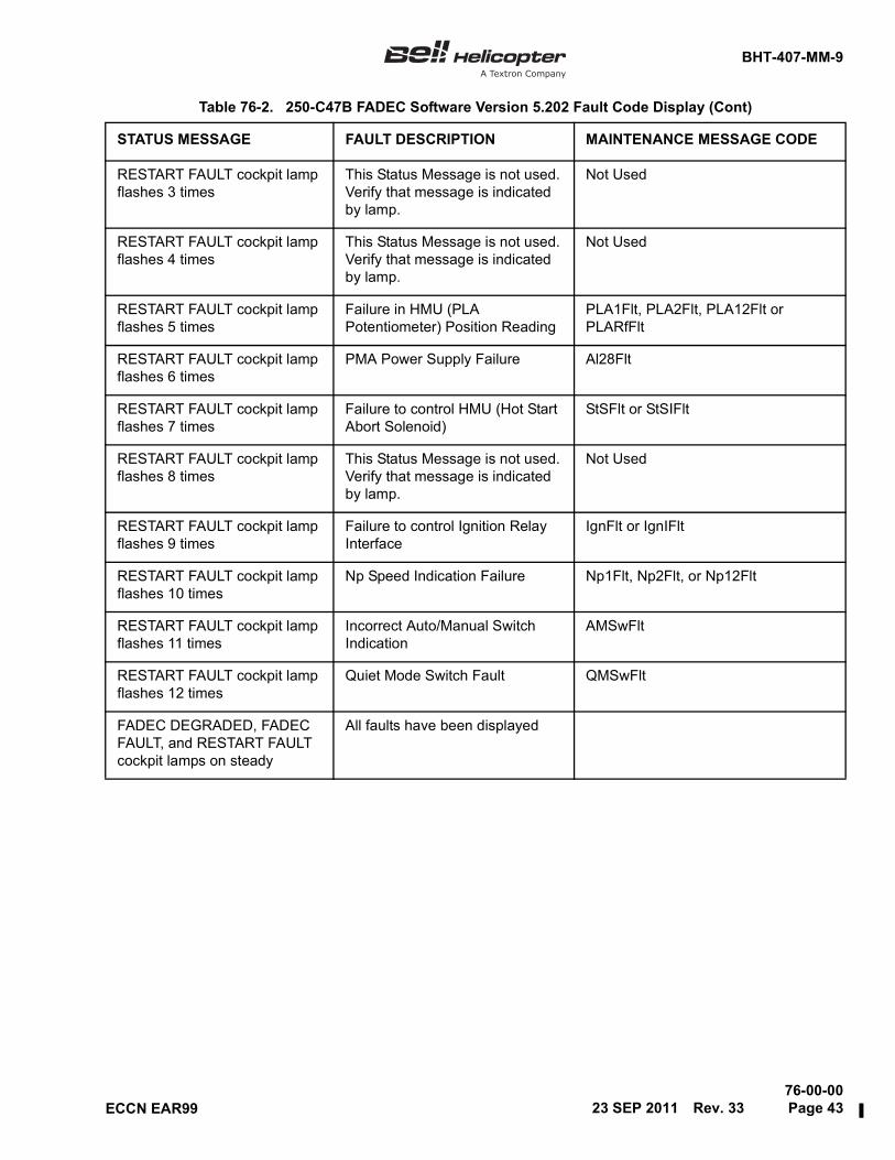
BHT-407-MM-9
76-00-0023 SEP 2011 Rev. 33 Page 43ECCN EAR99
RESTART FAULT cockpit lamp flashes 3 times
This Status Message is not used. Verify that message is indicated by lamp.
Not Used
RESTART FAULT cockpit lamp flashes 4 times
This Status Message is not used. Verify that message is indicated by lamp.
Not Used
RESTART FAULT cockpit lamp flashes 5 times
Failure in HMU (PLA Potentiometer) Position Reading
PLA1Flt, PLA2Flt, PLA12Flt or PLARfFlt
RESTART FAULT cockpit lamp flashes 6 times
PMA Power Supply Failure Al28Flt
RESTART FAULT cockpit lamp flashes 7 times
Failure to control HMU (Hot Start Abort Solenoid)
StSFlt or StSIFlt
RESTART FAULT cockpit lamp flashes 8 times
This Status Message is not used. Verify that message is indicated by lamp.
Not Used
RESTART FAULT cockpit lamp flashes 9 times
Failure to control Ignition Relay Interface
IgnFlt or IgnIFlt
RESTART FAULT cockpit lamp flashes 10 times
Np Speed Indication Failure Np1Flt, Np2Flt, or Np12Flt
RESTART FAULT cockpit lamp flashes 11 times
Incorrect Auto/Manual Switch Indication
AMSwFlt
RESTART FAULT cockpit lamp flashes 12 times
Quiet Mode Switch Fault QMSwFlt
FADEC DEGRADED, FADEC FAULT, and RESTART FAULT cockpit lamps on steady
All faults have been displayed
Table 76-2. 250-C47B FADEC Software Version 5.202 Fault Code Display (Cont)
STATUS MESSAGE FAULT DESCRIPTION MAINTENANCE MESSAGE CODE

BHT-407-MM-9
76-00-00Page 44 Rev. 33 23 SEP 2011 ECCN EAR99
Table 76-3. 250-C47B FADEC Software Versions 5.356 and 5.358 (Reversionary Governor)Fault Code Display
STATUS MESSAGE FAULT DESCRIPTION MAINTENANCE MESSAGE CODE
FADEC DEGRADED cockpit lamp flashes 1 time
Primary Governor Failed AD12bitFlt, AD8bitFlt, ECUOTFlt, GainFlt, HLRfFLt, OffsFlt, PROMFlt, PW10Flt, RAMFlt, V15Flt, V5Flt, WDTFlt, CJCFlt, OrDiodeFlt, BacCompFlt, EEPROMFlt, ForCompFlt, P1Flt, SWIntFlt, TestCelFlt, UARTFlt, UUIntFlt, OSVFlt, NpOSFlt, OR28Flt, WDTTimeOut, ARINCFlt, ARINCHWFlt, SWCfgFlt, RGSDFlt,QRawFlt, T1BRawFlt, ESWRGFlt, ESW2RGFlt, ESW3RGFlt, ESW4RGFlt, ESW5RGFlt, SWConfigRGFlt, PwrRstFlt, RGSelSwFlt or NDOTWRCdRGFlt
FADEC DEGRADED cockpit lamp flashes 2 times
Reversionary Governor Failed AD10bitFltRG, PROMFltRG, RAMFltRG, RGOTFltRG, SWConfigFltRG, V10FltRG, V15nFltRG, V15pFltRG, V5qFltRG, WDTTimeOutRG, ARINCHdFltRG, ARINCFltRG, ARINCHWFltRG, BacCompFltRG, ForCompFltRG, Or28FltRG, OrDiodeFltRG, PW10LoFltRG, RGTempFltRG, SPITempFltRG, UARTFltRG, WDTFltRG, PGSDHdFltRG, PGSDFltRG, WfCorrPGHdFltRG, WfCorrPGFltRG, EngRnCtPGFltRG, EngRnTmPGFltRG, ESWPGFltRG, NpIncPGFltRG, Np2RawPGFltRG, P1RawPGFltRG, T1ARawPGFltRG, SwPwrFltRG
FADEC DEGRADED cockpit lamp flashes 3 times
Np Exceedance NpLmTOut
FADEC DEGRADED cockpit lamp flashes 4 times
Reversionary Governor did not Govern When Primary Governor Failed
ECUGovFltRG
FADEC DEGRADED cockpit lamp flashes 5 times
MGT Indication Failure MGTFlt
FADEC DEGRADED cockpit lamp flashes 6 times
This Status Message is not used. Verify that message is indicated by lamp.
Not Used
FADEC DEGRADED cockpit lamp flashes 7 times
Failure to control Auto/Manual Solenoid
AMSolFlt, AMSolFltRG
1

BHT-407-MM-9
76-00-0023 SEP 2011 Rev. 33 Page 45ECCN EAR99
FADEC DEGRADED cockpit lamp flashes 8 times
CIT Temperature Indication Failure
T1AFlt, T1ABFlt, T1BFltRG or T1DFltRG
FADEC DEGRADED cockpit lamp flashes 9 times
Metering Valve not in start position
OpenMvFlg
FADEC DEGRADED cockpit lamp flashes 10 times
Starter Relay Interface StrFlt
FADEC DEGRADED cockpit lamp flashes 11 times
Nr Sensor – Rotor Decay Anticipation
NrFlt
FADEC DEGRADED cockpit lamp flashes 12 times
Incorrect Overspeed Test Switch Indication
OSTstSwFlt
FADEC FAULT cockpit lamp flashes 1 time
HMU – Failure to control fuel flow
WfLimFlag, WfLimFlagRG
FADEC FAULT cockpit lamp flashes 2 times
This Status Message is not used. Verify that message is indicated by lamp.
Not Used
FADEC FAULT cockpit lamp flashes 3 times
Np Run Limit NpRLmTOut
FADEC FAULT cockpit lamp flashes 4 times
Failure in HMU Metering Valve Potentiometer Reading
WfMvFlt, WfStFlt or WfStFltRG
FADEC FAULT cockpit lamp flashes 5 times
Collective Pitch Potentiometer Indication Failure
CPFlt
FADEC FAULT cockpit lamp flashes 6 times
Failure to control HMU (Stepper motor)
StepCntFlt, SmFlt, AMSolFlt or SmFltRG
FADEC FAULT cockpit lamp flashes 7 times
This Status Message is not used. Verify that message is indicated by lamp.
Not Used
FADEC FAULT cockpit lamp flashes 8 times
Failure to control HMU (Overspeed Solenoid)
OSFlt
FADEC FAULT cockpit lamp flashes 9 times
Engine Surge Event SgFlag
FADEC FAULT cockpit lamp flashes 10 times
Ng Speed Indiction Failure Ng1Flt, Ng2Flt, Ng12Flt or Ng1FltRG
FADEC FAULT cockpit lamp flashes 11 times
Airframe Power Supply Failure AF28Flt or AF28FltRG
FADEC FAULT cockpit lamp flashes 12 times
Engine Overspeed OSFlag or OSEventLmpRG
Table 76-3. 250-C47B FADEC Software Versions 5.356 and 5.358 (Reversionary Governor)Fault Code Display (Cont)
STATUS MESSAGE FAULT DESCRIPTION MAINTENANCE MESSAGE CODE 1

BHT-407-MM-9
76-00-00Page 46 Rev. 33 23 SEP 2011 ECCN EAR99
RESTART FAULT cockpit lamp flashes 1 time
This Status Message is not used. Verify that message is indicated by lamp.
Not Used
RESTART FAULT cockpit lamp flashes 2 times
TMOP Sensor – Torque Indication Failure
QFltRG
RESTART FAULT cockpit lamp flashes 3 times
This Status Message is not used. Verify that message is indicated by lamp.
Not Used
RESTART FAULT cockpit lamp flashes 4 times
This Status Message is not used. Verify that message is indicated by lamp.
Not Used
RESTART FAULT cockpit lamp flashes 5 times
Failure in HMU (PLA Potentiometer) Reading
PLA1Flt, PLA2Flt, PLA12Flt or PLARfFlt
RESTART FAULT cockpit lamp flashes 6 times
PMA Power Supply Al28Flt or Al28FltRG
RESTART FAULT cockpit lamp flashes 7 times
Failure to control HMU (Hot Start Abort Solenoid)
StSFlt, StSIFlt, StSFltRG or StSIFltRG
RESTART FAULT cockpit lamp flashes 8 times
This Status Message is not used. Verify that message is indicated by lamp.
Not Used
RESTART FAULT cockpit lamp flashes 9 times
Failure to control Ignition Relay Interface
IgnFlt or IgnIFlt
RESTART FAULT cockpit lamp flashes 10 times
Np Speed Indication Failure Np1Flt, Np2Flt, NpDFlt, Np12Flt, NpDFltRG or Np1FltRG
RESTART FAULT cockpit lamp flashes 11 times
Incorrect Auto/Manual Switch Indication
AMSwFlt or AMSwFltRG
RESTART FAULT cockpit lamp flashes 12 times
Quiet Mode Switch QMSwFlt
FADEC DEGRADED, FADEC FAULT, and RESTART FAULT cockpit lamps on steady
All faults have been displayed
NOTE:
As applicable to 407GX helicopters S/N 54300 and subsequent, only the maintenance message codesare displayed on the FAULTS (ENG/ECU FAULTS) — BELL MAINTENANCE PAGE (Chapter 95) of theMulti-Function Display (MFD).
Table 76-3. 250-C47B FADEC Software Versions 5.356 and 5.358 (Reversionary Governor)Fault Code Display (Cont)
STATUS MESSAGE FAULT DESCRIPTION MAINTENANCE MESSAGE CODE 1
1

BHT-407-MM-9
76-00-0016 FEB 2012 Rev. 34 Page 47ECCN EAR99
76-40. FADEC FAULT CODES —PROCEDURE TO DETERMINE LASTENGINE RUN FAULTS FROM“CURRENT” FAULTS
The procedure to determine if the fault codesdisplayed are Last Engine Run faults or “current” faultsmay be accomplished by performing the steps inparagraph 76-39 with the throttle in the idle position.
With the throttle positioned to idle, any FADEC faultcode that is displayed will be a “current” fault.
In addition, if no FADEC related annunciators or CrewAlerting System (CAS) messages (407GX) aredisplayed with electrical power applied, the FADEC inAUTO mode and the throttle positioned to idle, no“current” faults exist.
76-41. CHECK RUN PROCEDURE
Following completion of any FADEC systemmaintenance, a successful check run procedure is tobe carried out prior to flight. Do the procedures fromthe BHT-407-FM-1 or BHT-407-FM-2 that follow:
NOTE
Following maintenance actions and prior toperforming check run procedure, ensure no“current” faults exist.
1. Apply electrical power to the helicopter andposition FADEC Mode switch to AUTO. Wait forcompletion of FADEC system self-test and positionthrottle to idle. If no FADEC related annunciators/CrewAlerting System (CAS) messages (407GX) areilluminated with the throttle positioned to idle, no“current” faults exist. If a fault is displayed, refer toparagraph 76-38.
2. Do the PREFLIGHT and PRESTART CHECKprocedures.
3. Do the ENGINE START procedure.
4. Do the FADEC MANUAL CHECK procedure.
5. Do the ENGINE RUNUP procedure.
6. Do the ENGINE SHUTDOWN procedure; use theOverspeed shutdown test.
7. Ensure the FADEC DEGRADED annunciator orCAS message (407GX) does not illuminate when NGspeed decays through 9.5%. If a fault is displayed,refer to paragraph 76-38 for a determination of faults/exceedances and required troubleshooting steps.
76-42. FADEC DOWNLOAD INTERVALS
The FADEC system is designed to notify operators offaults and exceedances as they occur or at shutdown/pre start-up. This is accomplished through annunciatordisplays on the caution, warning, and advisory panelor CAS messages (407GX). This design is sufficient toadvise operators when FADEC system maintenanceactions are required.
Bell Helicopter Textron’s recommendation to adviseoperators to carry out periodic FADEC downloads issolely intended to provide a means for all involved toprotect their interests should a discrepancy arise inregards to how or when a fault or exceedance wasrecorded.
Although a specific FADEC download interval is notrequired in accordance with Chapter 5 of theBHT-407-MM, Bell Helicopter Textron recommendsthat operators perform a download with theMaintenance Terminal under the following conditions:
• Every 300 hours of operation or annually
• Prior to and following completion of trainingflights (i.e., operation in MANUAL mode)
• Prior to operation and following return of thehelicopter by a 2nd party (i.e., leasing, rental,etc.)
• Prior to and following completion ofmaintenance actions by a maintenance facility
NOTE
In addition to the following informationconcerning the FADEC ECU, also refer toFAULTS (ENG/ECU FAULTS) andEXCEEDANCES & CHIP HISTORY —BELL MAINTENANCE PAGES(Chapter 95) for information on faults andexceedance recording within the GarminG1000H system (407GX).
The FADEC download should confirm the status ofCurrent Faults, Last Engine Run Faults, Accumulated

BHT-407-MM-9
76-00-00Page 48 Rev. 33 23 SEP 2011 ECCN EAR99
Faults, Time Stamped Faults (fault history), andExceedance Data (engine history) (paragraph 76-38).A download of possible FADEC ECU recorded NG,MGT, and torque (Q) exceedances is alsorecommended (paragraph 76-37). During thedownload procedure, a printout of the fault andexceedance data should be taken and kept on file. Iffaults or exceedances exist, determine if maintenanceactions are required.
To ensure the FADEC ECU is clear of all faults andexceedances prior to return of the helicopter toservice, complete the following steps:
1. Refer to Engine History Data Screen of theMaintenance Terminal and write down the Engine RunTime (EngRnTm) and Number of Engine Start(NumStrt) values.
2. Use the Engine History Data "Clear All" commandof the Maintenance Terminal. This will clear all faultsand exceedances from engine history.
3. Use Engine History "Edit" feature of theMaintenance Terminal to enter Engine Run Time(EngRnTm) and Number of Engine Start (NumStrt)values recorded in step 1.
4. Use the Fault History Data "Clear All" commandof the Maintenance Terminal. This will clear all faultsand exceedances from fault history.
By performing these recommended procedures,operators will be sure that the ECU is free of faults andexceedances.
76-43. ENGINE START —TROUBLESHOOTING
The following information is provided to assist introubleshooting engine starting problems. Thisinformation should be used in conjunction withRolls-Royce CSL-6108.
Lightoff parameters and standard characteristics canbe described as follows:
FADEC Software Versions 5.356 and 5.358 — OnceNG speed reaches 10% for ambient temperatures of80°F (26.6°C) or below, or 12% for ambienttemperatures above 80°F (26.6°C) the FADEC systemwill introduce fuel, detect the lightoff, and smoothly
accelerate the engine to idle while limiting MGT ifnecessary.
FADEC Software Version 5.202 — Once NG speedreaches 10% for ambient temperatures of 20°F(-6.7°C) or below, or 12% for ambient temperaturesabove 20°F (-6.7°C) the FADEC system will introducefuel, detect the lightoff, and smoothly accelerate theengine to idle while limiting MGT if necessary.
• A normal lightoff can be described as a startattempt that lights off at fuel introduction or 2%NG after fuel introduction.
• A delayed lightoff can be described as a startattempt that does not achieve lightoff untilapproximately 3 to 6% after fuel introduction.
• A failure to lightoff condition can be describedas a start attempt that fails to lightoffregardless of NG speed.
The most common factors contributing to startingproblems are:
• HMU pressurizing/shutoff valve leakage
• Improper fuel nozzle shimming
• Faulty fuel nozzle
• Fuel leakback into fuel cell
• Faulty igniter circuit
The following troubleshooting may be carried out inany order to isolate the problem.
1. The HMU pressurizing/shutoff valve may betested for leakage as follows:
a. Locate the fuel discharge fitting on HMU. Thisis the long-necked fitting located directly above thePower Lever Angle (PLA) quadrant on the HMU. Theoutlet of this HMU fitting faces aft and feeds the linesthat lead to the fuel nozzle. Once located, remove themetal line that attaches to the fitting.
b. Ensure the throttle is in cutoff and that theFADEC mode switch is in AUTO mode.
c. Apply electrical power to the helicopter, turnON one or both fuel boost/transfer pump switches, and

BHT-407-MM-9
76-00-0023 SEP 2011 Rev. 33 Page 49ECCN EAR99
OPEN the fuel shutoff valve. Confirm approximately10 to 15 PSI on the fuel pressure gauge.
NOTE
Starting problems have been identified withpressurizing valves that leak as little asthree drops per minute. If the engineexperiences a failure to lightoff because ofpressurizing/shutoff valve leakage, thesecond start attempt is usually successfulbecause the system has been purged.
It should also be stated that fuel leakagecould also occur back through the thermalrelief features of the airframe mounted fuelshutoff valve and fuel pump check valves(step 4). Experience has shown however,that leakage through the HMU pressurizing/shutoff valve almost always occurs at amuch lower pressure than that which isrequired to crack the thermal relief valveson the airframe side. This is why we use the10 to 15 PSI output of the boost pumps tocheck the HMU pressurizing/shutoff valve(i.e., this pressure is below the crackingpressure of airframe thermal relief valves).
d. Monitor the discharge fitting for leakage(dripping) over a 5-minute period. If any leakage isdetected, the HMU will need to be replaced to resolvethe starting problem (paragraph 76-45). If leakage isdetected, count the number of drops per minute andprovide this information on the removal tag.
2. Information on fuel nozzle shimming follows:
a. Although most engines will haveapproximately 4 1/2 to 5 1/2 shims installed under thenozzle, the only way to positively confirm the actualinstalled depth of the nozzle is to carry out themeasurement procedure in Chapter 73-10-03 of theRolls-Royce C47B Operation and MaintenanceManual. Once the installed depth of the nozzle isdetermined, you can calculate how much additionalshimming may be added to move the nozzle furtheraft.
b. If you are in a position where you don’t havethe tools to measure the installed depth, a general ruleof thumb is to add 1/2 shim or 1 full shim maximum,and give it a try. Regardless of the shimming added, itmust be ensured that the nozzle has 3 full threads forengagement.
3. Information on fuel nozzle replacement follows:
a. If nozzle shimming does not improve lightoffcharacteristics and no problems are found during anyof the tests provided, nozzle replacement should beconsidered.
b. Prior to replacing the fuel nozzle you maywant to carry out the fuel nozzle inspection portion ofChapter 73-10-03 of the Rolls-Royce C47B Operationand Maintenance Manual. This test allows you to lookat the spray pattern of the nozzle.
4. Information on fuel leakback to the fuel cellfollows:
This test will confirm if the check/thermal relief valvesin the main fuel cell are allowing fuel to drain back intothe fuel cell. This test will require the helicopter to sitfor approximately 10 to 12 hours (overnight or thenumber of hours it takes between shutdown and startto experience your specific starting problem) and maybe conducted as follows:
a. Remove the inlet line to the airframe fuel filter(inboard line) and suspend it so that the opening in thefitting is facing up.
b. Open the fuel shutoff valve.
c. Fill the inlet line to the top of the fitting withfuel and loosely cover the fitting with a plastic bag toprevent contamination (air must be allowed to enterthe bag).
d. Allow the helicopter to sit for approximately 10to 12 hours (overnight) or the number of hours it takesfor you to experience your specific starting problem.
e. The next morning, or following the number ofhours it takes for you to experience your specificstarting problem, inspect the line to see if any fuel hasdrained back. If fuel has drained back, refill the linewith fuel using a syringe to measure the amount of fuelthat is required to refill the line. If it only takes a fewcc’s to refill the line (due to evaporation or the effectsof expansion/contraction), drain back is not an issueand it will confirm that the check/thermal relief valvesare not leaking. If the amount of fuel required to refillline is representative of a leak, the check valvesshould be cleaned, repaired or replaced (Chapter 28).
5. The following will provide information to test theigniter circuit.

BHT-407-MM-9
76-00-00Page 50 Rev. 34 16 FEB 2012 ECCN EAR99
This test may be repeated as required to ensure theAUTO RELIGHT annunciator is illuminating and thatthe igniter is firing 100% of the time. If this test provessuccessful, but you feel that the igniter may not befiring during an actual start attempt, it is suggestedthat someone (or two people) stand by the igniterduring start and listen for actual firing. Although thismethod of testing may not be the most scientific, it issimple and accurate. It should also be stated that thefiring of the igniter on the 250-C47B engine is muchsofter sounding than on C20, C28, or C30 engines.
NOTE
Prior to checking the ignition system,ensure there is no fuel in the combustionsection of the engine. If in doubt, conduct adry motoring run (BHT-407-FM-1 orBHT-407-FM-2).
Following completion of the ignition systemcheck, ensure the FADEC mode switch isrepositioned to AUTO prior to conducting astart.
a. Position the FADEC mode switch intoMANUAL (innermost position) with the battery switchOFF and external power not applied.
b. Pull the NG indicator circuit breaker.
c. Ensure the throttle is positioned to cutoff andthe fuel valve is closed.
d. Position the battery switch to ON. Once theinstrument check light goes out on the caution panel,the AUTO RELIGHT annunciator will illuminate andthe igniter will fire continuously.
e. To deactivate the igniter, position the batteryswitch to OFF.
f. To make sure the igniter will fire 100% of thetime, repeat this test procedure as required. Followingtesting, ensure the FADEC mode switch isrepositioned to AUTO and the NG circuit breaker isclosed.
g. If the igniter always fires during this testprocedure, but you feel that during actual startattempts that the igniter is not firing, it isrecommended that the starter relay 1K1 be replaced(Chapter 96). This is based on the fact that the abovetest procedure uses the auto relight circuitry to test thesystem and the normal start circuitry through thestarter relay is bypassed.
6. Information on testing results follow:
a. Based on the results of all theabove-mentioned tests, a determination can be madeon the possible corrective action or actions. Followingany corrective action, monitor subsequent starts veryclosely to determine if the lightoff characteristics havebeen improved. Do not make more than one change tothe system at any given time, unless you areabsolutely sure that multiple problems exist.
b. If all testing fails to identify the problem (startscontinue to fail or be delayed), it is recommended thatthe HMU be replaced. Although this should beaccomplished as a last resort only, it is possible thatthe HMU may have an intermittent internal problem,which is contributing to the start problem.
c. Return helicopter to flyable condition.

BHT-407-MM-9
76-00-0016 FEB 2012 Rev. 34 Page 51ECCN EAR99
HYDROMECHANICAL ENGINE CONTROLS
76-44. HYDROMECHANICAL UNIT (HMU)
76-45. HYDROMECHANICAL UNIT (HMU) —REMOVAL
NOTE
Refer to Chapter 12 for information on FuelSystem — General Servicing Instructions.
1. Disconnect electrical power from helicopter.
2. Remove airframe drain line (1, Figure 76-10) andfuel line (2).
3. Disconnect tube assembly (1, Figure 76-11) fromlever (2) by removing nut (14), washer (12), pennywasher (13), and bolt (11).
NOTE
HMU can be removed withstarter-generator installed.
4. Refer to Rolls-Royce 250-C47B Operations andMaintenance Manual, Publication CSP 21001 forremaining procedure to remove HMU.
NOTE
The following recommendations will aid incorrectly orientating the lever (2) andtoothed spacer (8) during installation ofreplacement HMU. Prior to removing leverand toothed spacer from HMU, positionHMU lever (3) to allow installation of 0.156inch (3.96 mm) rigging pin. Note orientationof lever to a reference point of your choiceon HMU. Additionally, match-mark matedposition of toothed spacer to lever with felttipped marker or equivalent item. Ensurerigging pin is installed during removal ofnut (9).
5. If replacement HMU is to be installed, remove nut(9), washer (10), lever (2), and toothed spacer (8).
6. If replacement HMU is to be installed, remove allfittings for installation into replacement unit.
76-46. HYDROMECHANICAL UNIT (HMU) —INSTALLATION
NOTE
Refer to Chapter 12 for information on FuelSystem — General Servicing Instructions.
1. Refer to Rolls-Royce 250-C47B Operations andMaintenance Manual, Publication CSP 21001 forinstallation instructions.
2. Install airframe drain line (1, Figure 76-10) andfuel line (2).
3. If previously removed, install toothed spacer (8,Figure 76-11), lever (2), washer (10), and nut (9). Priorto torquing nut (9), orientate lever and toothed spacer(8) to position noted during removal procedure. Torquenut with 0.156 inch (3.96 mm) rigging pin installedthrough HMU lever (3) and into HMU rigging pin hole.If position of lever and toothed spacer was not notedduring the removal procedure, refer to appropriaterigging procedure per step 5.
NOTE
Install bolt (11, Figure 76-11, Detail C) withhead of bolt outboard. Install large pennywasher (13) against head of bolt (11).There is no washer installed between lever(2) and rod end of tube assembly (1).
4. Install tube assembly (1) to lever (2) by installingbolt (11), penny washer (13), washer (12), and nut(14).
5. Confirm throttle rigging. Refer to paragraph76-47.
6. Perform air purge and HMU piston parkingprocedures in accordance with Rolls-Royce 250-C47BOperation and Maintenance Manual, Publication CSP21001 (Chapter 73-00-00).
7. Perform Check Run Procedure (paragraph76-41).
T

BHT-407-MM-9
76-00-00Page 52 Rev. 33 23 SEP 2011 ECCN EAR99
Figure 76-10. HMU — Removal/Installation407MM_76_0013
1. Drain line2. Fuel line into HMU
(from air frame fuel filter)
1
2

BHT-407-MM-9
76-00-0023 SEP 2011 Rev. 33 Page 53ECCN EAR99
Figure 76-11. Engine Control Rigging (Sheet 1 of 3)407MM_76_0014
DETAIL A
B
A
SURFACE OFENGINE PAN (REF)
RIGGING PINHOLE (HMU LEVER)
0.156 IN. (3.96 mm)
RIGGING PINHOLE (HMU)
STA
10°MIN.
DO NOT ADJUST
MIN. STOP
MAX. STOP
POSITION "X''(THROTTLE INIDLE DETENT)
168.78
SEE DETAIL ESEE DETAIL C
FWD
SEE DETAIL A
7109
1
SEE DETAIL D
SEE DETAIL B
5 4
5
6
3
8
2
8
7

BHT-407-MM-9
76-00-00Page 54 Rev. 33 23 SEP 2011 ECCN EAR99
Figure 76-11. Engine Control Rigging (Sheet 2 of 3)407MM_76_0015
STA. 155.00FIREWALL
RIGGING DIMENSIONS (NOMINAL)
C E
D5
4
1418
11
1312
1516
5
161718
1516
1718
6
6
1
34
4
2
4
16
DETAIL D
VIEW LOOKING FORWARD
AFTDETAIL B
DETAIL C
3.00 IN.(76.2 mm)
0.46 IN.(11.68 mm)
0.82 IN.(20.83 mm)
4.28 IN.(108.71 mm)
2.00 IN.(50.8 mm)
DIMENSION A DIMENSION B DIMENSION C DIMENSION D DIMENSION E
1
21

BHT-407-MM-9
76-00-00
ECCN EAR99
Figure 76-11. Engine Control Rigging (Sheet 3 of 3)407MM_76_0016
18.17.16.
11.
13.
15.14.
12.
9.10.
8.7.
2.
6.5.4.3.
1.
Washer
Cotter pinNut
Washer (Penny)Washer
Serrated washer (Toothed spacer)
Tube assemblyThrottle control cable
Tube assembly
WasherBolt
BoltNut
Nut
Bellcrank
HMU leverLever
Hydromechanical unit (HMU)
to helicopter due to rigging requirements.Exact dimensions may vary from helicopterDimensions are for guidance only.
Throttle closed 10° minimum.
cotter pin engagement.washer may be added to accommodateOne additional thick washer or thin
Position bolt head inboard.
Position bolt head outboard.
Penny washer against bolt head (11).
NOTES
19. Fireshield
Rotation (indexing) of serrated washer(8) will allow minor positioning adjustment of lever (2).
DETAIL E
1
2
3
4
5
6
7
CORROSION PREVENTIVE COMPOUND (C-101)
LOCKWIRE (C-405)
80 TO 120 IN-LBS(9.04 TO 12.43 Nm)
8 7
2
9
10
19
3
Roll pin installed in rod end. Do not adjust this end of tube assembly during rigging procedure.
8
23 SEP 2011 Rev. 33 Page 55/56


BHT-407-MM-9
76-00-0016 FEB 2012 Rev. 34 Page 57ECCN EAR99
MECHANICAL ENGINE CONTROLS
76-47. THROTTLE/FLY DETENT RIGGINGPROCEDURE
NOTE
The following information is only applicableto Model 407 Helicopters S/N 53390 andsubsequent (including 407GX) and thosethat have complied with ASB 407-99-31.
The throttle positions referred to in thefollowing procedure reflect those stated inthe BHT-407-FM-1 or BHT-407-FM-2. Thepositions are Closed, Idle, FLY, and FullOpen.
1. Open the access door for the right side of theengine (Chapter 53).
2. Disconnect the tube assembly (1, Figure 76-11)and tube assembly (5) from bellcrank (6).
3. Install a rigging pin of 0.156 inch (3.96 mm)diameter through the HMU lever (3) into the rig pinhole on the HMU (7). The rig pin hole is located at the35° power lever angle (PLA) marking on the HMU.
NOTE
HMU rigging pin must be installed for step 4through step 9.
4. Rotate pilot's throttle grip to the idle position.
5. Adjust the throttle control cable (4) to dimensions“D” and “E”.
6. Adjust tube assembly (5) to dimension “C”. Installtube assembly to bellcrank (6) with attaching hardware(Detail D).
7. Measure dimension “A”. Bellcrank (6) position “X”(throttle in idle position) is to be within ±0.05 inch(0.127 mm) of dimension “A”. If required, adjust rodend of tube assembly (5) to obtain dimension “A”±0.05 inch (0.127 mm).
8. Adjust the tube assembly (1) thread length todimension “B”.
9. Install tube assembly (1) to bellcrank (6) withattaching hardware (Detail D). To enable installation oftube assembly onto lever (2), position lever asrequired. Fine adjustments of lever can be made byindexing the serrated washer (8). Install lever withattaching hardware (Detail E). With rig pin installed,torque nut (9) . Install tube assembly to lever withattaching hardware (Detail C).
10. Remove rigging pin and roll throttle to the FullOpen and Closed Positions. Verify contact is madeagainst both upper and lower HMU stops (min stopand max stop). If applicable, this check must also beperformed with copilot's throttle.
CAUTION
DO NOT ADJUST MINIMUM ANDMAXIMUM STOPS ON HMU.
11. If adjustment is required to ensure contact at bothstops, adjust tube assembly (1) dimension “B”, orrotate lever (2) by indexing the serrated washer (8)between the lever and HMU (7). When an adjustmentis made to achieve contact at either HMU stop, the idleposition must be reverified using the rigging pin andstep 10 must be repeated.
12. If it is not possible to contact both HMU stops,rigging may be accomplished, per step 11 procedure,to achieve a maximum 0.020 inch (0.51 mm) gap atthe maximum stop (lower stop). If it is still not possibleto contact the minimum stop (upper stop) rigging maybe accomplished, per step 11 procedure, to achieve amaximum 0.020 inch (0.51 mm) gap at the minimumstop. The Idle position must be verified with the riggingpin.
NOTE
On 407GX helicopters S/N 54300 andsubsequent, the PLA angle may also beobtained by viewing the Data Status Pageand referring to the PWR LVR ANG value.For instructions to view the Data StatusPage, refer to Accessing the BellMaintenance Pages on the Multi-FunctionDisplay (MFD) (Chapter 95).
T

BHT-407-MM-9
76-00-00Page 58 Rev. 34 16 FEB 2012 ECCN EAR99
13. An additional method to confirm throttle rigging(Power Lever Angle – PLA) at the Closed, Idle, andFull Open Positions may be accomplished with theMaintenance Terminal. Refer to the FADECMaintenance Terminal User's Guide, located within theRolls-Royce 250-C47B Operation and MaintenanceManual, for operational information. From the MainMenu, select Real Time Data. From the Real TimeData Menu, select Analog Parameters. The AnalogParameters screen will provide information on PLAposition. With the throttle positioned to Closed, Idle,and Full Open, the corresponding PLA signals must beas indicated in Table 76-4.
14. Roll the throttle to the Closed position. Ensure thebellcrank (6) and the tube assembly (5) do not lockover their pivot point. Ensure an acute angle of 10°minimum between station 168.78 and the centerline ofthe arm of the bellcrank that attaches to the tube (1)(Figure 76-11).
15. Once rigged configuration is obtained, confirmproper installation and safteying of all hardware.Perform throttle linkage clearance checks in enginecompartment. Ensure throttle turns smoothly throughcomplete operating range. If required, refer toparagraph 76-48 for throttle/FLY detent friction checkprocedure or to paragraph 76-49 for throttle/FLYdetent friction adjustment.
NOTE
Throttle/FLY detent friction values must bein accordance with paragraph 76-48 prior toproceeding to step 16.
16. Rig the detented FLY throttle position as follows:
NOTE
The following rigging steps are veryimportant to ensure the helicopter willoperate at 100% NP/NR in AUTO mode,with the throttle positioned to FLY. Thesteps also configure the system to providea NG speed of approximately 90% inMANUAL mode, with the throttle positionedto FLY. The Maintenance Terminal isnecessary to complete the following riggingsteps. Refer to the FADEC Maintenance
Terminal User's Guide, located within theRolls-Royce 250-C47B Operation andMaintenance Manual, for operationalinformation.
NOTE
On 407GX helicopters S/N 54300 andsubsequent, the PLA angle may also beobtained by viewing the Data Status Pageand referring to the PWR LVR ANG value.For instructions to view the Data StatusPage, refer to Accessing the BellMaintenance Pages on the Multi-FunctionDisplay (MFD) (Chapter 95).
a. Loosen four setscrews (3, Figure 76-12).
b. Connect Maintenance Terminal and applyhelicopter electrical power. Select Real Time Data –Analog Parameters.
c. Monitor Power Lever Angle (PLA) on AnalogParameters screen. Position the throttle grip assembly(1) to Full Open and then roll the throttle down until aPLA value of 70° is obtained.
d. Maintain the 70° PLA value with throttleposition and turn the ferrule/bezel (2) until the ballplunger (6) engages the groove of FLY detent (7).
e. Tighten the four setscrews (3) sufficiently tokeep the ferrule/bezel (2) in position.
f. Turn the throttle grip assembly (1) from FullOpen until the ball plunger (6) is engaged in thegroove of FLY detent (7). Make sure that the PLAvalue is 69.5 to 70.5°, when the throttle is positionedfrom Full Open into the FLY detent. If necessary,readjust per step 16 until the 69.5 to 70.5 PLA value isobtained.
g. If repainting of the throttle position line (5) isrequired, position throttle until ball plunger (6) engagesin groove of FLY detent (7). Paint white line 0.06 inch(1.52 mm) wide by 0.25 inch (6.35 mm) long, alignedwith the FLY position of throttle.
17. Perform check run procedure (paragraph 76-41).

BHT-407-MM-9
76-00-0023 SEP 2011 Rev. 33 Page 59ECCN EAR99
Figure 76-12. Rigging Fly Detent (Sheet 1 of 2)407MM_76_0017
DETAILS OMITTED FOR CLARITY
FERRULE SETSCREWPOSITIONS (4 PLACES)
THROTTLE GRIP ASSEMBLY -RECESSED AREAS FOR FERRULESETSCREWS (4 PLACES)
SECTION A-A
1
1
0.06 IN.(1.52 mm)
0.25 IN.(6.35 mm)
A A
2 5
2
4
3
1

BHT-407-MM-9
76-00-00Page 60 Rev. 33 23 SEP 2011 ECCN EAR99
Figure 76-12. Rigging Fly Detent (Sheet 2 of 2)
LDGLTS
BOTH
FWD
OFFDISENG
START
FLOATINFLATE
FLOATARM
1. Throttle grip assembly2. Ferrule/bezel3. Setscrew (4 Reqd)4. Collective switch box5. Throttle position line6. Ball plunger7. FLY detent8. Detent block
NOTESThere is only one position, between ferrule and throttle grip,where all four setscrews will fully engage.
Mark with 299-947-096 epoxy paint, color to be white No. 37925per FED-STD-595 (C-207).
VIEW C
DETAILS OMITTED FOR CLARITYSECTION B-B C
2
6
3
7
8
1
2
B B
1
4
407MM_76_0018_c01
(TYPICAL)

BHT-407-MM-9
76-00-0010 DEC 2012 Rev. 35 Page 61Export Classification C, ECCN EAR99
76-48. THROTTLE/FLY DETENT FRICTIONCHECK
NOTE
The following information is only applicableto Model 407 Helicopters S/N 53390 andsubsequent (including 407GX) and thosethat have complied with ASB 407-99-31.
Copilot throttle friction will be higher thanpilot throttle friction due to gearing in backof pilot collective assembly. With dualcontrols installed, pilot’s throttle friction maybe set to a minimum of 5 inch-pounds(0.56 Nm) to obtain a maximum resultantcopilot throttle friction of 16.5 inch-pounds(1.86 Nm) after break-away torque.
1. Wrap a suitable length of cord (C-480), orequivalent around the pilot's throttle grip and attach afish scale to the cord.
NOTE
Depress the idle release button during thefollowing step. Friction will increase as ballplunger (6, Figure 76-12) rides on surfaceof detent block (8).
2. Pull the fish scale to turn the pilot's throttle gripfrom the Closed position to the FLY detent position.Verify that the fish scale indicates a maximum of 10±0.5 pounds (4.5 ±0.23 kg) after the initial breakawayforce. The operation should be smooth throughout therange.
3. Turn the pilot's throttle to put the ball plunger (6,Figure 76-12) near the groove of the FLY detent (7).Pull the fish scale to move the ball plunger in and outof the groove. Verify the fish scale value is 14 to 15±0.5 pounds (6.3 to 6.8 ±0.23 kg) when the plunger ispulled through the detent.
4. If throttle or FLY detent friction requiresadjustment, refer to paragraph 76-49.
76-49. THROTTLE/FLY DETENT FRICTIONADJUSTMENT
NOTE
The following information is only applicableto Model 407 Helicopters S/N 53390 andsubsequent (including 407GX) and thosethat have complied with ASB 407-99-31.
Table 76-4. Throttle Rigging Parameters
THROTTLE POSITION PLAMAXIMUM DISTANCE BETWEEN HMU LEVER AND HMU STOP (MINIMUM/MAXIMUM)
Closed -2.5 to +2.5° 0.020 inch (0.51 mm) (Minimum Stop)
Idle 34 to 36°
FLY 69.5 to 70.5°
Full Open 97.5 to 102.5° 0.020 inch (0.51 mm) (Maximum Stop)
Refer to BHT-ALL-SPM for specifications.
MATERIALS REQUIRED
NUMBER NOMENCLATURE
C-480 Cord
Refer to BHT-ALL-SPM for specifications.
MATERIALS REQUIRED
NUMBER NOMENCLATURE
C-480 Cord

BHT-407-MM-9
76-00-00Page 62 Rev. 35 10 DEC 2012 Export Classification C, ECCN EAR99
Copilot throttle friction will be higher thanpilot throttle friction due to gearing in backof pilot collective assembly. With dualcontrols installed, pilot’s throttle friction maybe set to a minimum of 5 inch-pounds(0.56 Nm) to obtain a maximum resultantcopilot throttle friction of 16.5 inch-pounds(1.86 Nm) after break-away torque.
1. Adjust ball plunger (6, Figure 76-12) so that itdoes not contact face of detent block (8). If ballplunger has lost its thread locking capability, replacewith new unit.
2. With the use of a 3/16 inch allen key, remove thethrottle friction adjustment setscrew (1, Figure 76-13).Remove spring washers (2) and plug (3). Inspectwashers and plug for condition. If washers are flat,cracked, or broken, replace with serviceable washers.Inspect plug for wear. Face of plug is to be flat. Ifgroove is worn into face of plug, replace withserviceable unit.
3. Examine the setscrew (1) to see if there is ateflon locking element.
NOTE
Do not adjust the setscrew in too far.Damage to the spring washers will occur,which will require removal of spring tensionwashers to restack or replace them.
4. If the setscrew (1) has a locking element, installthe removed components in the reverse order ofstep 2 and go to step 6.
5. If the setscrew has no locking element, it isrecommended to replace the setscrew (1) with a newself-locking setscrew (P/N NAS1081-6B8).
6. Tighten setscrew (1) until you have a slightfriction when the throttle grip is turned.
NOTE
If dual controls installed, pilot throttlefriction may be set to a minimum of5 inch-pounds to obtain a maximum
resultant copilot throttle friction of16.5 inch-pounds after break-away torque.
7. To adjust the throttle friction grip setscrew (1) toget a fish scale value of 10 ±0.5 pounds (4.5 ±0.23kg), after the initial breakaway force, do the procedurethat follows:
a. Wrap a suitable length of cord (C-480), orequivalent around the pilot's throttle grip and attach afish scale to the cord.
b. Depress the Idle detent button and pull thefish scale to rotate the throttle from the Closed positionto the Full open position.
c. Adjust setscrew (1) to get the required frictionvalue.
8. Adjust the ball plunger (6, Figure 76-12) to adepth that lets it lightly contact the face of detentblock (8).
9. To adjust ball plunger (6) to get a peak rotationalvalue of between 4 to 5 pounds (1.8 to 2.3 kg) inexcess of throttle friction adjustment in step 7, whenthe ball plunger rides through groove of the FLY detent(7), do the procedure that follows:
a. Turn the throttle grip assembly (1) to put theball plunger (6) near the groove of the FLY detent (7).
b. Wrap a suitable length of cord (C-480), orequivalent around the pilot's throttle grip assembly (1)and attach a fish scale to the cord.
c. Pull the fish scale to move the ball plunger (6)in and out of the groove. Adjust ball plunger to makesure the fish scale value is 14 to 15 ±0.5 pounds (6.3to 6.8 ±0.23 kg) when the plunger is pulled throughgroove of the FLY detent (7).
10. Following the throttle and FLY detent frictionadjustments, make sure the operation of the throttle issmooth and that a positive indication is felt when theball plunger (6) is engaged in the FLY detent (7). Ifapplicable, also use the copilot's throttle to confirm apositive indication is felt in the FLY Detent.
11. Perform Check Run Procedure (paragraph76-41).

BHT-407-MM-9
76-00-0023 SEP 2011 Rev. 33 Page 63ECCN EAR99
Figure 76-13. Collective Throttle Friction
1. Setscrew
NOTES
2. Spring washers3. Plug
THROTTLE GRIP (REF)
Do not adjust the setscrew in too far. Damage to the springwashers will occur which will require removal of the spring tensionwashers to restack or replace them.
Stack washers as shown to create spring assembly.
USE 3/16" ALLENWRENCH TO REMOVE/INSTALL
SECTION A-A
A
A
3
1
2
1
2
1
2
(TYPICAL)
407MM_76_0019_c01

BHT-407-MM-9
76-00-00Page 64 Rev. 33 23 SEP 2011 ECCN EAR99
76-50. THROTTLE CONTROL CABLE
76-51. THROTTLE CONTROL CABLE —REMOVAL
1. Access the throttle control cable (68,Figure 76-14).
NOTE
Prior to removing cable, note installedbends and radiuses. Also, note clampingpositions on cable and installed adjustmentof external threaded areas of cable. Thisinformation may be useful duringinstallation of cable.
There can be two thin washers(AN960JD10L) in place of one AN960PD10washer (2).
2. Remove the nut (1) and the washer (2) from thebolt (4).
3. Remove the bolt (4) from the spacer (5), the rodend (6), and the throttle clevis (3).
4. Loosen the jam nut (7) and remove the rod end(6) from the adapter (8).
5. Loosen the jam nut (9) and remove the adapter(8) from the ball joint (10).
6. Remove the seal nut assembly (12) from thethrottle control cable (68).
7. Remove the inboard jam nut (15) from the throttlecontrol cable (68).
8. Remove the screw (19), washer (20), and thespacer (21) from the clamp (22). Remove the clamp(22) from the throttle control cable (68).
9. Remove the screw (27), the washer (26), and thenut (23) from the clamp (25). Remove the clamp (25)from the throttle control cable (68).
10. Remove the screw (28), the washer (29), and thespacer (30) from the clamp (31). Remove the clamp(31) from the throttle control cable (68).
11. Remove the nut (32), the washer (33), the screw(34), and washer (35) from the clamp (39) and thebracket (41).
12. Remove the two nuts (43), the two washers (44),and the two screws (45) from the two clamps (46).Remove the two clamps (46) from the throttle controlcable (68).
13. Remove the two nuts (47), the two washers (48),the two spacers (49) from the two screws (50).Remove the two clamps (51) from the throttle controlcable (68).
14. Remove the nut (52), the washer (53), the spacer(54), and the screw (55) from the clamp (56).
15. Remove the nut (57), the washer (58), and thescrew (59) from the clamp (60), and the clamp (61).Remove the clamp (60) from the throttle controlcable (68).
16. Remove the screw (62), the washer (63), and thespacer (64) from the clamp (65). Remove the clamp(65) from the throttle control cable (68).
17. Loosen the four nuts (69) and the nut (70) andremove the throttle control cable (68) from the balljoint (71).
18. Remove the throttle control cable (68) from thehelicopter.
76-52. THROTTLE CONTROL CABLE —INSPECTION
1. Examine the throttle control cable for smoothoperation.
2. Examine the throttle control cable for signs ofdamage to the threaded ends.
3. Examine the throttle control cable insulation forsigns of damage and cracks.

BHT-407-MM-9
76-00-0023 SEP 2011 Rev. 33 Page 65ECCN EAR99
Figure 76-14. Throttle Control Cable (Sheet 1 of 5)407MM_76_0020
SEE DETAIL D
DETAIL A
DETAIL B
SEE DETAIL ESEE DETAIL B
SEE DETAIL A
7069
71
6766
6766
6766
6766
72 68
SEE DETAIL C
27
2625
24
26
23
22
2019
21
1511
1716
1716
18
1312
14
10
98
76
4
53
21
1

BHT-407-MM-9
76-00-00Page 66 Rev. 33 23 SEP 2011 ECCN EAR99
Figure 76-14. Throttle Control Cable (Sheet 2 of 5)407MM_76_0021
DETAIL C
15 11 10 9 8 7
6
1312
14
1.250 IN.(31.75 mm)
APPROXIMATELY
DETAIL D
68 69 69 70 71
2.0 IN.(50.8 mm)
APPROXIMATELY
18

BHT-407-MM-9
76-00-0023 SEP 2011 Rev. 33 Page 67ECCN EAR99
Figure 76-14. Throttle Control Cable (Sheet 3 of 5)407MM_76_0030
72
68
DETAIL G
DETAIL H
DETAIL E
SEE DETAIL N
SEE DETAIL P
SEE DETAIL M
SEE DETAIL L
SEE DETAIL K
SEE DETAIL J
SEE DETAIL F
SEE DETAIL G
SEE DETAIL H
575860
59
61
5048
49
51
47
DETAIL F
64
65
63
62

BHT-407-MM-9
76-00-00Page 68 Rev. 33 23 SEP 2011 ECCN EAR99
Figure 76-14. Throttle Control Cable (Sheet 4 of 5)

BHT-407-MM-9
76-00-0023 SEP 2011 Rev. 33 Page 69ECCN EAR99
Figure 76-14. Throttle Control Cable (Sheet 5 of 5)407MM_76_0023
1.2.3.4.5.6.7.8.9.
10.11.12.13.14.15.16.17.18.19.20.21.22.23.24.
25.26.27.28.29.30.31.32.33.34.35.36.37.38.39.40.41.42.43.44.45.46.47.48.
49.50.51.52.53.54.55.56.57.58.59.60.61.62.63.64.65.66.67.68.69.70.71.
NutWasherCollective throttle clevisBoltSpacerRod endJam nutAdapterJam nutBall jointNutSeal nut assembly (13, 14)SleeveNutJam nutScrewWasherBracketScrewWasherSpacerClampNutAdapter
ClampWashersScrewScrewWasherSpacerClampNutWasherScrewWasherWasherWasherWasherClampScrewBracketSpacerNutWasherScrewClampNutWasher
SpacerScrewClampNutWasherSpacerScrewClampNutWasherScrewClampClampScrewWasherSpacerClampSleeveTubeThrottle control cableJam nut (qty. 4)Jam nutBall jointGrommet72.
Two thin washers may be substituted for one regular washer. Install one thin washer under bolt head and install one thin washerunder nut.
1
CORROSION PREVENTIVE COMPOUND (C-101)
LOCKWIRE (C-405)
NOTE
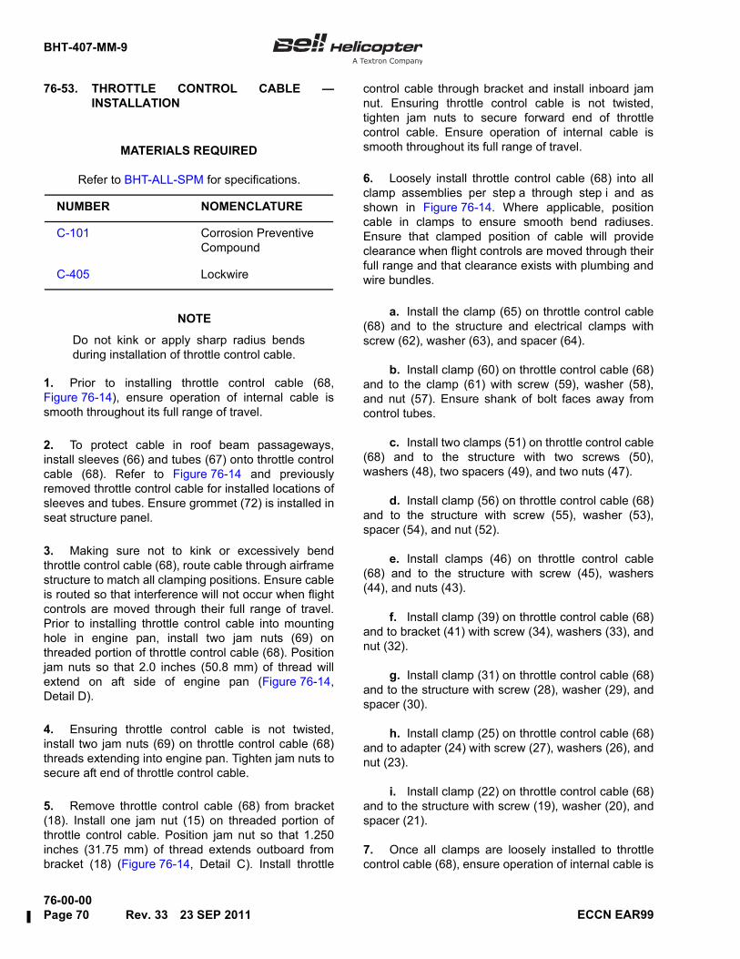
BHT-407-MM-9
76-00-00Page 70 Rev. 33 23 SEP 2011 ECCN EAR99
76-53. THROTTLE CONTROL CABLE —INSTALLATION
NOTE
Do not kink or apply sharp radius bendsduring installation of throttle control cable.
1. Prior to installing throttle control cable (68,Figure 76-14), ensure operation of internal cable issmooth throughout its full range of travel.
2. To protect cable in roof beam passageways,install sleeves (66) and tubes (67) onto throttle controlcable (68). Refer to Figure 76-14 and previouslyremoved throttle control cable for installed locations ofsleeves and tubes. Ensure grommet (72) is installed inseat structure panel.
3. Making sure not to kink or excessively bendthrottle control cable (68), route cable through airframestructure to match all clamping positions. Ensure cableis routed so that interference will not occur when flightcontrols are moved through their full range of travel.Prior to installing throttle control cable into mountinghole in engine pan, install two jam nuts (69) onthreaded portion of throttle control cable (68). Positionjam nuts so that 2.0 inches (50.8 mm) of thread willextend on aft side of engine pan (Figure 76-14,Detail D).
4. Ensuring throttle control cable is not twisted,install two jam nuts (69) on throttle control cable (68)threads extending into engine pan. Tighten jam nuts tosecure aft end of throttle control cable.
5. Remove throttle control cable (68) from bracket(18). Install one jam nut (15) on threaded portion ofthrottle control cable. Position jam nut so that 1.250inches (31.75 mm) of thread extends outboard frombracket (18) (Figure 76-14, Detail C). Install throttle
control cable through bracket and install inboard jamnut. Ensuring throttle control cable is not twisted,tighten jam nuts to secure forward end of throttlecontrol cable. Ensure operation of internal cable issmooth throughout its full range of travel.
6. Loosely install throttle control cable (68) into allclamp assemblies per step a through step i and asshown in Figure 76-14. Where applicable, positioncable in clamps to ensure smooth bend radiuses.Ensure that clamped position of cable will provideclearance when flight controls are moved through theirfull range and that clearance exists with plumbing andwire bundles.
a. Install the clamp (65) on throttle control cable(68) and to the structure and electrical clamps withscrew (62), washer (63), and spacer (64).
b. Install clamp (60) on throttle control cable (68)and to the clamp (61) with screw (59), washer (58),and nut (57). Ensure shank of bolt faces away fromcontrol tubes.
c. Install two clamps (51) on throttle control cable(68) and to the structure with two screws (50),washers (48), two spacers (49), and two nuts (47).
d. Install clamp (56) on throttle control cable (68)and to the structure with screw (55), washer (53),spacer (54), and nut (52).
e. Install clamps (46) on throttle control cable(68) and to the structure with screw (45), washers(44), and nuts (43).
f. Install clamp (39) on throttle control cable (68)and to bracket (41) with screw (34), washers (33), andnut (32).
g. Install clamp (31) on throttle control cable (68)and to the structure with screw (28), washer (29), andspacer (30).
h. Install clamp (25) on throttle control cable (68)and to adapter (24) with screw (27), washers (26), andnut (23).
i. Install clamp (22) on throttle control cable (68)and to the structure with screw (19), washer (20), andspacer (21).
7. Once all clamps are loosely installed to throttlecontrol cable (68), ensure operation of internal cable is
Refer to BHT-ALL-SPM for specifications.
MATERIALS REQUIRED
NUMBER NOMENCLATURE
C-101 Corrosion Preventive Compound
C-405 Lockwire
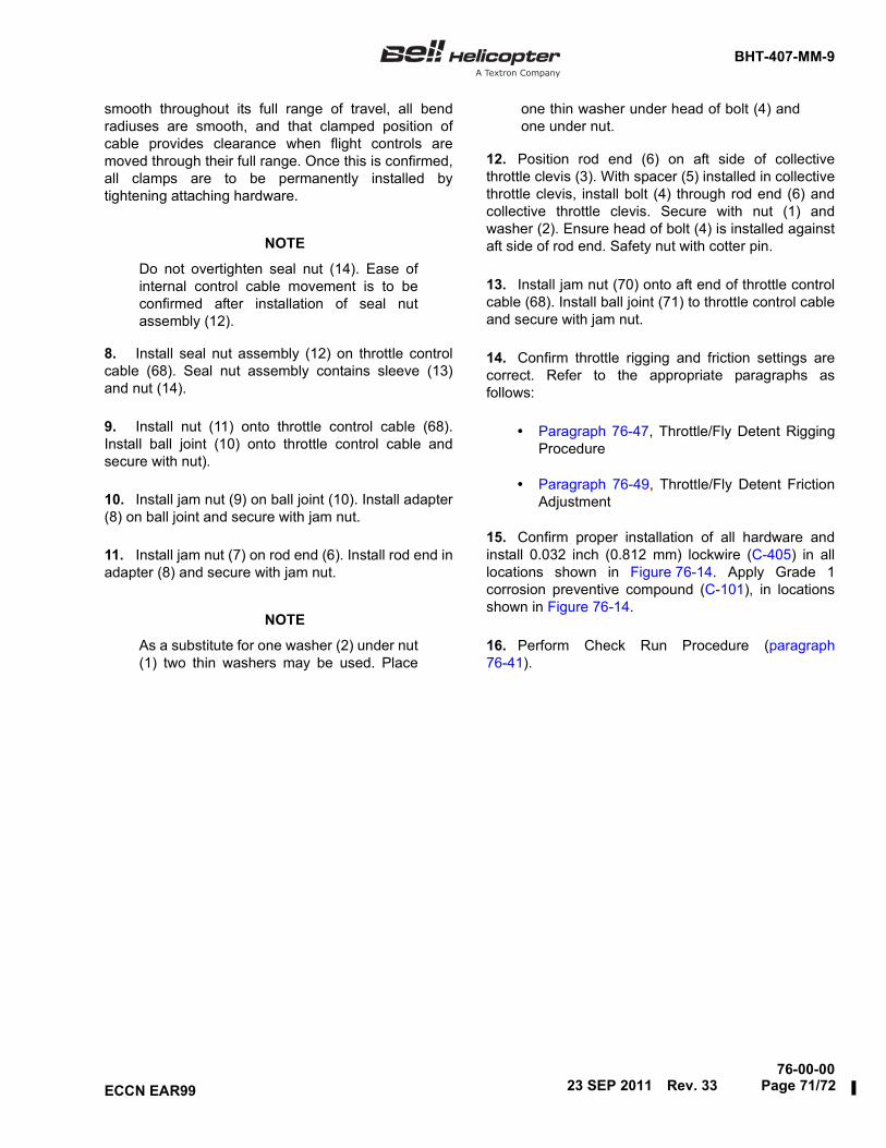
BHT-407-MM-9
76-00-00
ECCN EAR99
smooth throughout its full range of travel, all bendradiuses are smooth, and that clamped position ofcable provides clearance when flight controls aremoved through their full range. Once this is confirmed,all clamps are to be permanently installed bytightening attaching hardware.
NOTE
Do not overtighten seal nut (14). Ease ofinternal control cable movement is to beconfirmed after installation of seal nutassembly (12).
8. Install seal nut assembly (12) on throttle controlcable (68). Seal nut assembly contains sleeve (13)and nut (14).
9. Install nut (11) onto throttle control cable (68).Install ball joint (10) onto throttle control cable andsecure with nut).
10. Install jam nut (9) on ball joint (10). Install adapter(8) on ball joint and secure with jam nut.
11. Install jam nut (7) on rod end (6). Install rod end inadapter (8) and secure with jam nut.
NOTE
As a substitute for one washer (2) under nut(1) two thin washers may be used. Place
one thin washer under head of bolt (4) andone under nut.
12. Position rod end (6) on aft side of collectivethrottle clevis (3). With spacer (5) installed in collectivethrottle clevis, install bolt (4) through rod end (6) andcollective throttle clevis. Secure with nut (1) andwasher (2). Ensure head of bolt (4) is installed againstaft side of rod end. Safety nut with cotter pin.
13. Install jam nut (70) onto aft end of throttle controlcable (68). Install ball joint (71) to throttle control cableand secure with jam nut.
14. Confirm throttle rigging and friction settings arecorrect. Refer to the appropriate paragraphs asfollows:
• Paragraph 76-47, Throttle/Fly Detent RiggingProcedure
• Paragraph 76-49, Throttle/Fly Detent FrictionAdjustment
15. Confirm proper installation of all hardware andinstall 0.032 inch (0.812 mm) lockwire (C-405) in alllocations shown in Figure 76-14. Apply Grade 1corrosion preventive compound (C-101), in locationsshown in Figure 76-14.
16. Perform Check Run Procedure (paragraph76-41).
23 SEP 2011 Rev. 33 Page 71/72


BHT-407-MM-9
76-00-0016 FEB 2012 Rev. 34 Page 73ECCN EAR99
ELECTRICAL ENGINE CONTROLS
76-54. ELECTRICAL ENGINE CONTROLS —GENERAL
This section of the chapter will cover removal,inspection, and installation of airframe mountedelectrical items that are part of the FADEC system. Forinformation on FADEC related airframe electricalcircuits, which integrate with the FADEC, refer toChapters 95, 96, and 98.
For information on FADEC related cockpit switches(i.e., FADEC auto/manual switch) refer to Chapter 96.For additional information on FADEC MaintenanceGuidelines, refer to Rolls-Royce 250-C47 CommercialService Letter CSL-6069.
76-54A. Electrical Engine Controls — Applicationof Contact Enhancer
Moisture contamination of electrical connectors hasbeen found to be the cause of electrical discrepancies.It has also been found to cause corrosion andpremature wear of the contacts. Most of theseproblems have been reported on helicopters thatoperate in high relative humidity environments.
To reduce the possibility of these occurrences anddowntimes due to moisture releated problems, BellHelicopter has approved the use of contact enhancer(C-052) on the mating surfaces of connectors that areoutside of the cabin area, including the top deck,transmission area, lower shell, and tailboom areas.
In specific regards to the FADEC system, it isrecommended that operators apply contact enhancer(C-052) in accordance with TB 407-08-81 in thefollowing locations during associated componentinstallation and/or replacement procedures:
76-55. ELECTRONIC CONTROL UNIT (ECU)
76-56. Electronic Control Unit (ECU) — RemovalS/N 53000 Through 53749 Pre TB407-07-75
NOTE
Bell Helicopter Textron recommends thatthe ECU be checked for faults andexceedances prior to removal. This may beaccomplished with use of the MaintenanceTerminal. Refer to the FADEC MaintenanceTerminal User's Guide, located within theRolls-Royce 250-C47B Operation andMaintenance Manual, for operationalinformation.
The Fault History option of the Maintenance TerminalMain Menu is to be used to check for Current, LastEngine Run, Accumulated and Time Stamped Faults.The Engine History option is to be used to check theEngine History Data screen for exceedances. If faultsor exceedances exist, determine appropriatemaintenance action. Refer to paragraph 76-38
Refer to BHT-ALL-SPM for specifications.
MATERIALS REQUIRED
NUMBER NOMENCLATURE
C-052 Contact Enhancer
REFERENCE DESIGNATOR
NOMENCLATURE
1A50P1 Connector, FADEC/ECU
1A50P2 Connector, FADEC/ECU
4J1/4P1 Connector, FADEC/Engine Compartment
4J2/4P2 Connector, FADEC/Forward Roof Disconnect
1P8/1J8 Aft Electrical Roof Disconnect
1P3/1J3 Forward Electrical Roof Disconnect
1B7P1 Engine Torque Pressure Transducer
1B8P1 NR Monopole Sensor

BHT-407-MM-9
76-00-00Page 74 Rev. 34 16 FEB 2012 ECCN EAR99
(Determination of Faults/Exceedances and RequiredTroubleshooting Steps).
A check for FADEC ECU recorded NG, MGT, andtorque (Q) exceedances is also recommended(paragraph 76-37).
Refer to Engine History Data Screen of MaintenanceTerminal and save or hand copy Engine Run Time(EngRnTm) and Number of Engine Start (NumStrt)values. These values can be input into replacementECU following installation.
1. Disconnect the helicopter electrical power.
2. Gain access to the ECU by removing the forwardtransmission cowling (Chapter 53).
NOTE
Make sure that you do not cause damageto the contacts during removal of the ECUconnectors. Put protective covers on theECU and harness connectors immediatelyafter removal.
3. Disconnect the FADEC harness electricalconnectors (1, 2, Figure 76-15) from the ECU.
4. Remove the screw (4), lockwasher (5), bondingstrap (7), and washer (6) from the ECU (3).
5. Remove the bolts (8, 9, 10, and 11) and washers(13) from the top of the ECU mounting pads.
6. Remove the ECU (3).
7. Capture the washers (13) located on top of theroof shell inserts for the ECU (3).
8. Remove spacers (12) from the rubber isolationdampers with finger pressure (Figure 76-15, Detail B).
76-57. Electronic Control Unit (ECU) — RemovalS/N 53000 Through 53749 Post TB407-07-75 and S/N 53750 and Subsequent(Including 407GX)
NOTE
Bell Helicopter Textron recommends thatthe ECU be checked for faults andexceedances prior to removal. This may be
accomplished with use of the MaintenanceTerminal. Refer to the FADEC MaintenanceTerminal User’s Guide, located within theRolls-Royce 250-C47B Operation andMaintenance Manual, for operationalinformation.
NOTE
In addition to the following informationconcerning the FADEC ECU, also refer toFAULTS (ENG/ECU FAULTS) andEXCEEDANCES & CHIP HISTORY —BELL MAINTENANCE PAGES(Chapter 95) for information on faults andexceedance recording within the GarminG1000H system (407GX).
The Fault History option of the Maintenance TerminalMain Menu is to be used to check for Current, LastEngine Run, Accumulated and Time Stamped Faults.The Engine History option is to be used to check theEngine History Data screen for exceedances. If faultsor exceedances exist, determine appropriatemaintenance action. Refer to paragraph 76-38(Determination of Faults/Exceedances and RequiredTroubleshooting Steps).
A check for FADEC ECU recorded NG, MGT, andtorque (Q) exceedances is also recommended(paragraph 76-37).
Refer to Engine History Data Screen of MaintenanceTerminal and save or hand copy Engine Run Time(EngRnTm) and Number of Engine Start (NumStrt)values. These values can be input into replacementECU following installation.
1. Disconnect the helicopter electrical power.
2. Gain access to the ECU by removing the forwardtransmission cowling (Chapter 53).
NOTE
Make sure that you do not cause damageto the contacts during removal of the ECUconnectors. Put protective covers on theECU harness connectors immediately afterremoval.
3. Disconnect the FADEC harness electricalconnectors (1 and 2, Figure 76-16) from the ECU.

BHT-407-MM-9
76-00-0016 FEB 2012 Rev. 34 Page 75ECCN EAR99
Figure 76-15. Electronic Control Unit (ECU) — Removal/Installation S/N 53000 Through 53749Pre TB 407-07-75 (Sheet 1 of 2)
NO OBJECT BEYOND THIS POINT 407MM_76_0024a
12
13
6
5
13
3
12
13
8
136
(TYPICAL)
8
11
9
10
22 3 4
9
10
8
10
432110
13
14
11
9
CC
4
5
6 7 7
8
911
11
11
9
10
SEE DETAIL A
DETAIL A
SEE DETAIL BDETAIL B
SECTION C-C(TYPICAL)
HELICOPTERSTRUCTURE
HELICOPTERMOUNTEDNUTPLATE
11

BHT-407-MM-9
76-00-00Page 76 Rev. 34 16 FEB 2012 ECCN EAR99
Figure 76-15. Electronic Control Unit (ECU) — Removal/Installation S/N 53000 through 53749Pre TB 407-07-75 (Sheet 2 of 2)
NO OBJECT BEYOND THIS POINT 407MM_76_0024b
NOTES
30 TO 40 IN-LBS(3.4 TO 4.5 Nm)
Disconnect the electrical power from the helicopter whenyou remove or install the ECU.
Make sure that you do not cause damage to the connectorcontacts when you remove or install.
Put protective covers on the ECU and the harnessconnectors immediately after the removal.
Make sure that the red band on each ECU connector is notvisible after you install the harness connectors.
Install one spacer in each of the ECU mounting padisolation dampers.
Install one washer on the top of and three washers undereach ECU mount.
Pre S/N 53200 or Pre TB 407-98-9, bonding strapMS25083-2BB6, S/N 53200 and subsequent or PostTB 407-98-9, bonding strap 961114-1.
Use only screw MS35206-261. Use of any other type screwwill damage the threads of the ECU casing.
Inboard mounting pad isolation damper color (RED).
Outboard mounting pad isolation damper color (GREEN).
It is recommended to apply contact enhancer (C-052) perTB 407-08-81.
ECU-to-airframe electrical connectorECU-to-engine electrical connectorECUScrew (MS35206-261)Lockwasher (MS35338-43)Plain washer (NAS1149D0332J)Bonding strapBolt (NAS6203-12)Bolt (NAS6203-12)Bolt (NAS6203-12)Bolt (NAS6203-18)Spacer (NAS43DD3-34N)Washer (AN970-3)Decal (31-053-18CFHP)
1.2.3.4.5.6.7.8.9.
10.11.
13.12.
1
2
3
4
5
6
7
8
14.
9
10
11

BHT-407-MM-9
76-00-0016 FEB 2012 Rev. 34 Page 77ECCN EAR99
Figure 76-16. Electronic Control Unit (ECU) — Removal/Installation S/N 53000 Through 53749 Post TB 407-07-75 and S/N 53750 and Subsequent (Sheet 1 of 2)
NO OBJECT BEYOND THIS POINT 407MM 76 0031a
12
5
12
3
12
8
125
(TYPICAL)
8
11
9
10
11
9
10SEE DETAIL A
DETAIL A
DETAIL B
SECTION C-C(TYPICAL)
C
C
2 3 41
8
8
7
6
2 3 4
8
9 2
6
5
4
11
103
13
1
SEE DETAIL B
8
7
HELICOPTERMOUNTEDNUTPLATE
HELICOPTERSTRUCTURE
9
9
98

BHT-407-MM-9
76-00-00Page 78 Rev. 34 16 FEB 2012 ECCN EAR99
Figure 76-16. Electronic Control Unit (ECU) — Removal/Installation S/N 53000 Through 53749 Post TB 407-07-75 and S/N 53750 and Subsequent (Sheet 2 of 2)
NO OBJECT BEYOND THIS POINT 407MM 76 0031b
NOTES
30 TO 40 IN-LBS(3.4 TO 4.5 Nm)
Disconnect the electrical power from the helicopter when you remove or install the ECU.
Make sure that you do not cause damage to the connector contacts when you remove or install.
Put protective covers on the ECU and the harness connectors immediately after the removal.
Make sure that the red band on each ECU connector is not visible after you install the harnessconnectors.
Install one washer on the top of and three washers under each ECU mount.
Pre S/N 53200 or Pre TB 407-98-9, bonding strap MS25083-2BB6, S/N 53200 and subsequent or PostTB 407-98-9, bonding strap 961114-1.
Use only screw MS35206-261. Use of any other type screw will damage the threads of the ECUcasing.
Mounting pad isolation dampers contain integral one piece spacer assembly.
It is recommended to apply contact enhancer (C-052) perTB 407-08-81.
ECU-to-airframe electrical connectorECU-to-engine electrical connectorECUScrew (MS35206-261)Lockwasher (MS35338-43)Plain washer (NAS1149D0332J)Bonding strapBolt (NAS6203-14)Bolt (NAS6203-14)Bolt (NAS6203-14)Bolt (NAS6203-20)Washer (AN970-3)Decal (31-053-18CFHP)
1.2.3.4.5.6.7.8.9.
10.11.
13.12.
1
2
3
4
5
6
7
8
9

BHT-407-MM-9
76-00-0016 FEB 2012 Rev. 34 Page 79ECCN EAR99
4. Remove the screw (4), lockwasher (5), bondingstrap (7), and washer (6) from the ECU (3).
5. Remove the bolts (8, 9, 10, and 11) and washers(12) from the top of the ECU mounting pads.
6. Remove the ECU (3).
7. Capture the washers (12) located on top of theroof shell inserts for the ECU (3).
76-58. Electronic Control Unit (ECU) —Inspection
NOTE
For additional information on care andinspection of the FADEC system, refer toRolls-Royce 250-C47 Series CSL-6069.
1. Examine the ECU outer case for signs of damageand corrosion.
2. Examine the ECU electrical receptacles fordamage (e.g., bent pins) and corrosion.
3. Examine the ECU mounting pad isolationdampers for condition and security.
4. Examine the ECU pressure sensing (P1) port forblockage.
5. Ensure the “NO STEP” decal (Bell HelicopterTextron P/N 31-053-18CFHP) is installed on top outercase of ECU.
6. Ensure ECU mounting fasteners on roof shell arechecked for condition and security.
7. Inspect ECU bonding strap for condition andsecurity.
76-59. Electronic Control Unit (ECU) —Installation S/N 53000 Through 53749 PreTB 407-07-75
NOTE
ECU has removable NAS43DD3-34Nspacers. Install spacers in accordance withstep 1.
1. Install the four spacers (12, Figure 76-15,Detail B) into the ECU mounting pads.
2. Install a stack-up of three washers (13) over eachof the four ECU mounting positions.
3. Position the ECU (3) mounting pads over thewashers (13).
4. Install one washer (13) on top of each of the fourECU mounting pads.
NOTE
ECU mounting bolts (8, 9, and 10) have a-12 grip length. ECU mounting bolt (11) hasa -18 grip length.
5. Install ECU mounting bolts (8, 9, 10, and 11).Torque bolts .
6. Install washer (6), bonding strap (7), lockwasher(5), and screw (4) into the ECU.
NOTE
Only remove protective covers on the ECUand FADEC harness connectors just priorto installation. Make sure that you do notcause damage to the contacts duringinstallation of the ECU connectors. Makesure that the red band on each ECUelectrical receptacle is not visible after
Refer to BHT-ALL-SPM for specifications.
MATERIALS REQUIRED
NUMBER NOMENCLATURE
C-052 Contact Enhancer
T

BHT-407-MM-9
76-00-00Page 80 Rev. 34 16 FEB 2012 ECCN EAR99
installation of the FADEC harnessconnectors.
NOTE
It is recommended to apply contactenhancer (C-052) to the electricalconnectors per TB 407-08-81.
7. Install the FADEC harness electrical connectors(1 and 2) to the ECU (3).
NOTE
Bell Helicopter Textron recommends thatthe ECU be checked for faults andexceedances following installation (prior tothe first engine start). This will ensure theECU is free of faults and exceedances priorto return to service. This may beaccomplished with use of the MaintenanceTerminal. Refer to the FADEC MaintenanceTerminal User's Guide, located within theRolls-Royce 250-C47B Operation andMaintenance Manual, for operationalinformation.
The Fault History option of the Maintenance TerminalMain Menu can be used to check for Current, LastEngine Run, Accumulated and Time Stamped Faults.The Engine History option can be used to check theEngine History Data screen for exceedances. Any lastEngine Run Faults, Accumulated Faults, orExceedances should be cleared prior to first enginestart. The Fault History Data "Clear All" command ofthe Maintenance Terminal may be used to ensureFault History is clear of faults or exceedances. Toensure NG, MGT, and Torque (Q) exceedances do notexist in ECU memory, use Engine History Data “ClearAll” command of the Maintenance Terminal. If active“current” faults exist, determine appropriatemaintenance action (paragraph 76-38).
Use Engine History “Edit” feature of MaintenanceTerminal to enter Engine Run Time (EngRnTm) andNumber of Engine Starts (NumStrt) that were saved orhand copied during ECU removal.
8. Apply electrical power to the helicopter andposition FADEC Mode switch to AUTO. Ensure noactive Current Faults exist. This can be accomplishedby waiting for completion of FADEC system self-testand positioning throttle to idle. If no FADEC relatedlights are illuminated on the caution, warning, advisory
panel with the throttle positioned to idle, no “current”faults exist. If a fault is displayed, refer to paragraph76-38.
9. Install required cowlings (Chapter 53).
10. Perform check run procedure (paragraph 76-41).
76-60. Electronic Control Unit (ECU) —Installation S/N 53000 Through 53749 PostTB 407-07-75 and 53750 and Subsequent(Including 407GX)
1. Install a stack-up of three washers (12,Figure 76-16, Detail B) over each of the four ECUmounting positions.
2. Position the ECU (3) mounting pads over thewashers (12).
3. Install one washer (12) on top of each of the fourECU mounting pads.
NOTE
ECU mounting bolts (8,9, and 10) have a-14 grip length. ECU mounting bolt (11) hasa -20 grip length.
4. Install ECU mounting bolts (8, 9, 10, and 11).Torque bolts .
5. Install washer (6), bonding strap (7), lockwasher(5), and screw (4) into the ECU.
NOTE
Only remove protective covers on the ECUand FADEC harness connectors just priorto installation. Make sure that you do notcause damage to the contacts duringinstallation of the ECU connectors. Makesure that the red band on each ECUelectrical receptacle is not visible after
Refer to BHT-ALL-SPM for specifications.
MATERIALS REQUIRED
NUMBER NOMENCLATURE
C-052 Contact Enhancer
T

BHT-407-MM-9
76-00-0016 FEB 2012 Rev. 34 Page 81ECCN EAR99
installation of the FADEC harnessconnectors.
NOTE
It is recommended to apply contactenhancer (C-052) to the electricalconnectors per TB 407-08-81.
6. Install the FADEC harness electrical connectors(1 and 2) to the ECU (3).
NOTE
Bell Helicopter Textron recommends thatthe ECU be checked for faults andexceedances following installation (prior tothe first engine start). This will ensure theECU is free of faults and exceedances priorto return to service. This may beaccomplished with use of the MaintenanceTerminal. Refer to the FADEC MaintenanceTerminal User’s Guide, located within theRolls-Royce 250-C47B Operation andMaintenance Manual, for operationalinformation.
NOTE
In addition to the following informationconcerning the FADEC ECU, also refer toFAULTS (ENG/ECU FAULTS) andEXCEEDANCES & CHIP HISTORY —BELL MAINTENANCE PAGES(Chapter 95) for information on faults andexceedance recording within the GarminG1000H system (407GX).
The Fault History option of the Maintenance TerminalMain Menu can be used to check for Current, LastEngine Run, Accumulated and Time Stamped Faults.The Engine History option can be used to check theEngine History Data screen for exceedances. Any lastEngine Run Faults, Accumulated Faults, orExceedances should be cleared prior to first enginestart. The Fault History Data "Clear All" command ofthe Maintenance Terminal may be used to ensureFault History is clear of faults or exceedances. Toensure NG, MGT, and Torque (Q) exceedances do notexist in ECU memory, use Engine History Data “ClearAll” command of the Maintenance Terminal. If active“current” faults exist, determine appropriatemaintenance action (paragraph 76-38).
Use Engine History “Edit” feature of MaintenanceTerminal to enter Engine Run Time (EngRnTm) andNumber of Engine Starts (NumStrt) that were saved orhand copied during ECU removal.
7. Apply electrical power to the helicopter andposition FADEC Mode switch to AUTO. Ensure noactive Current Faults exist. This can be accomplishedby waiting for completion of FADEC system self-testand positioning throttle to idle. If no FADEC relatedlights are illuminated on the caution, warning, advisorypanel with the throttle positioned to idle, no “current”faults exist. If a fault is displayed, refer to paragraph76-38.
8. Install required cowlings (Chapter 53).
9. Perform check run procedure (paragraph 76-41).
76-61. COLLECTIVE PITCH TRANSDUCER (CPT)
The Collective Pitch (CP) transducer is installed underthe copilot seat. The transducer tells the FADECsystem the rate of movement of the collective controlstick. The transducer is an electrical potentiometerthat is connected to the airframe at one end andconnected to a clamp assembly installed on thecollective jackshaft. When the collective control stick islifted or lowered, the transducer increases ordecreases in length, which changes the resistanceoutput to the FADEC system. The output signal allowsthe FADEC to provide anticipation logic, which helps toreduce main rotor RPM droop and overshoot.
76-62. Collective Pitch Transducer (CPT) —Removal
1. Disconnect helicopter electrical power.
2. Remove the copilot seat and seatback(Chapter 25).
3. Remove the metal copilot seat panel assembly.
4. Disconnect the CP transducer electricalconnector (1, Figure 76-17).
5. Remove the nut (2) and the spacer (3) from thescrew (4).
6. Remove the screw (4) and the washer (5) fromthe CP transducer (6) and the support (7).

BHT-407-MM-9
76-00-00Page 82 Rev. 33 23 SEP 2011 ECCN EAR99
Figure 76-17. Collective Pitch Transducer (CPT) — Removal/Installation (Sheet 1 of 3)407MM_76_0026
ADJUST MIDSTROKE POSITIONTO 6.18 IN. (156.9 mm)
WORK AID
COLLECTIVE PITCH TRANSDUCER RIGGING WORK AID
SEE DETAIL A
1213
89
10
11
1
32
7
4 5 6
DETAIL B
DETAIL A
0.25 IN.(6.35 mm)
0.125 IN.(3.17 mm)
STOCK
7.60 IN.(193.0 mm)
6.77 IN.(171.95 mm)
0.193 TO 0.198 IN.(4.90 TO 5.03 mm)
2 HOLES
0.38 IN.(9.65 mm)
0.50 IN.(12.7 mm)
6.18 IN.(156.9 mm)

BHT-407-MM-9
76-00-0023 SEP 2011 Rev. 33 Page 83ECCN EAR99
Figure 76-17. Collective Pitch Transducer (CPT) — Removal/Installation (Sheet 2 of 3)

BHT-407-MM-9
76-00-00Page 84 Rev. 33 23 SEP 2011 ECCN EAR99
Figure 76-17. Collective Pitch Transducer (CPT) — Removal/Installation (Sheet 3 of 3)407MM_76_0028
CLAMP
SCREW
SHOWN COLLECTIVE FULL UP
SUPPORT
When reinstalling collective link assembly tocollective lever, torque nut. See Detail D.
Transducer mounting faces of support (7) andclamp (12) are to be in-line.
NOTES
1. Electrical connector2. Nut3. Spacer4. Screw5. Washer6. Collective pitch transducer7. Support8. Nut9. Washer
10. Screw11. Spacer12. Clamp assembly13. Collective jackshaft14. Bolt15. Washer16. Nut17. Collective link assembly18. Collective lever
2
1
2
DETAIL F
DETAIL E
LBL8.05
WL28.62
7.47 IN.(189.7 mm)
6.77 IN.(171.95 mm)
STA73.12
WL28.62
WL21.03
STA71.03
95 TO 110 IN-LBS(10.7 TO 12.4 Nm)
CORROSION PREVENTIVE COMPOUND (C-101)

BHT-407-MM-9
76-00-0016 FEB 2012 Rev. 34 Page 85ECCN EAR99
7. Remove the nut (8) and the washer (9) from thescrew (10).
8. Remove the screw (10) and the spacer (11) fromthe clamp assembly (12) and the CP transducer (6).
9. Remove the CP transducer (6).
76-63. Collective Pitch Transducer (CPT) —Inspection
NOTE
For additional information on care andinspection of the FADEC system, refer toRolls-Royce 250-C47B Series CSL-6069.
1. Examine the CP transducer for signs of damage,pitting, and corrosion.
2. Examine the CP transducer, mounting support,and clamp assembly for condition, security, andeccentric bolt holes.
3. Examine the electrical leads for signs of chafingand damaged insulation. Examine the electricalconnector for condition.
4. Examine spherical bearings on CP transducer forcondition and security.
76-64. Collective Pitch Transducer (CPT) —Installation/Rigging
CAUTION
MAKE SURE THE COLLECTIVECONTROL SYSTEM IS RIGGED BEFORE
YOU RIG THE CP TRANSDUCER. REFERTO CHAPTER 67.
NOTE
It is recommended that the CP transducerworkaid be used to avoid damage to the CPtransducer (Figure 76-17, Detail B).
1. Adjust the collective pitch (CP) transducer (6,Figure 76-17, Detail A) to obtain 6.18 inch (156.9 mm)dimension between centers of the grounded bearingand adjustable rod end bearing with the transducermovable rod at the mid stroke position.
2. Remove forward transmission cowling(Chapter 53).
NOTE
As an alternate procedure to step 3 andstep 10, a hydraulic cart may be connectedto the helicopter (Chapter 29).
3. Remove attaching hardware between collectivelink assembly (17) and collective lever (18). Positioncollective link assembly clear of collective lever.
4. Raise collective stick until up-stop is contacted.Hold in position with collective friction (Figure 76-17,Detail C).
NOTE
If adjustments are required in the followingstep 5 or step 6, reposition clamp (12) asrequired. Tighten screws on clampmaintaining equal gaps between clamphalves. Do not tighten screws more thannecessary to hold adjustment.
5. Confirm clamp assembly (12) is installed oncollective jackshaft (13) at left butt line (LBL) 8.05(Figure 76-17, View E).
6. With collective full-up, confirm dimensionbetween mounting hole of support (7) and clamp (12)is 6.77 inch (171.95 mm). Once dimension has beenobtained, remove workaid if used. Refer toFigure 76-17, Detail B for recommended workaid.
7. Position the CP transducer (6, Figure 76-17)between the support (7) and the clamp assembly (12).
Refer to BHT-ALL-SPM for specifications.
MATERIALS REQUIRED
NUMBER NOMENCLATURE
C-101 Corrosion Preventive Compound

BHT-407-MM-9
76-00-00Page 86 Rev. 34 16 FEB 2012 ECCN EAR99
NOTE
The head of the screw (4) must pointinboard when installed.
8. Install the washer (5) and the screw (4) throughthe support (7) and the CP assembly (6).
9. Install the spacer (3) and the nut (2) on thescrew (4).
10. Prior to installing the CP transducer (6) to theclamp (12), make sure the CP transducer rod end willfit the clamp mounting hole position with collective fullup and collective full down without causing restrictionto collective travel or damage to CP transducer.
NOTE
The head of the screw (10) must pointoutboard when installed.
11. Install the spacer (11) and the screw (10) throughthe CP transducer (6) and the clamp assembly (12).
12. Install the washer (9) and the nut (8).
13. Apply Grade 1 corrosion preventive compound(C-101), as shown in Figure 76-17.
14. Connect the CP transducer electrical connector(1). Fold and secure the excess connector harnesswiring with lacing cord or plastic cable ties.
NOTE
If a collective pitch (CP) transducerfunctional test is to be carried out perparagraph 76-65, it should be conductedprior to accomplishment of step 15.
15. Reinstall collective link assembly (17) tocollective lever (18) with bolt (14), washers (15), andnut (16). Torque nut and apply Grade 1 corrosionpreventive compound (C-101) per Figure 76-17,Detail D.
16. Install forward transmission cowling (Chapter 53).
17. Install the metal copilot seat panel assembly.
18. Install copilot seat and seat back (Chapter 25).
19. Apply electrical power to the helicopter andposition FADEC Mode switch to AUTO. Ensure noactive “current” faults exist. This can be accomplishedby waiting for completion of FADEC system self-testand positioning throttle to idle. If no FADEC relatedlights/Crew Alerting System (CAS) messages (407GX)are illuminated with the throttle positioned to idle, no“current” faults exist. If a fault is displayed, refer toparagraph 76-38.
20. Perform check run procedure (paragraph 76-41).
76-65. Collective Pitch Transducer (CPT) —Functional Test
NOTE
The Maintenance Terminal will be requiredto complete the Functional Test.
1. Remove forward transmission cowling(Chapter 53).
NOTE
As an alternate procedure to step 2 andstep 5, a hydraulic cart may be connectedto the helicopter (Chapter 29).
2. Remove attaching hardware between collectivelink assembly (17) and collective lever (18). Positioncollective link assembly clear of collective lever(Figure 76-17, Detail C and Detail D).
NOTE
On 407GX helicopters S/N 54300 andsubsequent, the Collective Pitch (CP) anglemay also be obtained by viewing the DataStatus Page and referring to the % COLLEV POS value. For instructions to view theData Status Page, refer to Accessing theBell Maintenance Pages on theMulti-Function Display (MFD) (Chapter 95).
3. Install the Maintenance Terminal. Refer to theMaintenance Terminal Users Guide, located within theRolls-Royce 250-C47B Operation and MaintenanceManual for operating instructions.
a. Connect the helicopter electrical power.
b. Select Real Time Data from the Main Menu.
T

BHT-407-MM-9
76-00-0016 FEB 2012 Rev. 34 Page 87ECCN EAR99
c. Select Analog Parameters from the Real TimeData Menu.
d. View Analog Parameters for Collective Pitch(CP) reading.
NOTE
If step e and step f of this test are carriedout by disconnecting the CP transducerand moving the shaft of transducer byhand, it is quite possible that a fault will bedetected by the FADEC. This will bedisplayed as a FADEC DEGRADEDannunciator/Crew Alerting System (CAS)message (407GX). A defaulted CP valuewill then be displayed on the MaintenanceTerminal regardless of shaft position. Cyclehelicopter electrical power to remove thefault and defaulted CP value. Conductstep e and step f with CP transducerinstalled.
e. With collective full down (down stopcontacted, Figure 76-17, View C), CP is to be 0 to 5%.
RESULT:
• If collective pitch is 0 to 5% with collective fulldown proceed to step f.
CORRECTIVE ACTION:
• If collective pitch is not 0 to 5% with collectivefull down, confirm rigging per paragraph76-64. If rigging is acceptable, ensure noshorts or opens exist in wiring between CPtransducer and ECU. If wiring is acceptable,consider replacing CP transducer.
f. With collective full up (up-stop contacted,Figure 76-17, View C), CP is to be 95 to 100%.
RESULT:
• If collective pitch is 95 to 100% with collectivefull up proceed to step g.
CORRECTIVE ACTION:
• If collective pitch is not 95 to 100% withcollective full up, confirm rigging perparagraph 76-64. If rigging is acceptable,ensure no shorts or opens exist in wiring
between CP transducer and ECU. If wiring isacceptable consider replacing CP transducer.
g. Disconnect the electrical power from thehelicopter.
4. Remove the Maintenance Terminal.
5. Install attaching hardware between collective linkassembly (17) and collective lever (18) (Figure 76-17,Details C and D).
6. Install forward transmission cowling (Chapter 53).
76-66. COMPRESSOR INLET TEMPERATURE(CIT) SENSOR
The purpose of the Compressor Inlet Temperature(CIT) sensor is to provide the FADEC with informationon compressor air inlet temperature. The CIT sensor ismounted on the upper left-hand side of the forwardengine firewall. When installed, the actual temperatureprobe of the sensor is located on the forward side ofthe engine firewall. In this position, the probe of theCIT sensor is protected from foreign object damageand from ice buildup. The sensor has two temperaturesensing coils for redundancy.
76-67. Compressor Inlet Temperature (CIT)Sensor — Removal
1. Remove electrical power from the helicopter.
NOTE
Install protective plastic cap on connectorend of CIT sensor following removal.
2. Remove electrical connector (1, Figure 76-18)from CIT sensor (2).
3. Remove CIT sensor attaching screws (3) andwashers (4).
76-68. Compressor Inlet Temperature (CIT)Sensor — Inspection
NOTE
For additional information on care andinspection of the FADEC system, refer toRolls-Royce 250-C47B Series CSL-6069.

BHT-407-MM-9
76-00-00Page 88 Rev. 33 23 SEP 2011 ECCN EAR99
Figure 76-18. Compressor Inlet Temperature (CIT) Sensor — Removal/Installation407MM_76_0029
1. Electrical connector2. CIT sensor3. Screw4. Washer5. Forward engine firewall
LBL11.50
WL92.22
5
4
3
2
43
1

BHT-407-MM-9
76-00-0016 FEB 2012 Rev. 34 Page 89ECCN EAR99
1. Inspect CIT sensor and its electrical contacts(pins) for visible damage, moisture, and corrosion.
2. Inspect CIT sensor mating connector and itscontacts (sockets) for damage, moisture, andcorrosion.
3. Inspect condition of CIT mounting fasteners onfirewall.
76-69. Compressor Inlet Temperature (CIT)Sensor — Installation
1. Install CIT sensor to firewall with attaching screws(3, Figure 76-18) and washers (4).
NOTE
Remove protective plastic cap fromconnector end of CIT sensor just prior toinstallation of mating connector. Wheninstalling mating connector to CIT sensor,ensure contacts are not damaged and thatconnector is tightened until red line on CITsensor is no longer visible.
2. Install electrical connector (1) to CIT sensor (2).
3. Apply electrical power to the helicopter andposition FADEC Mode switch to AUTO. Ensure noactive Current Faults exist. This can be accomplishedby waiting for completion of FADEC system self-testand positioning throttle to idle. If no FADEC relatedlights are illuminated on the caution, warning, advisorypanel or the Crew Alerting System (CAS) (407GX)with the throttle positioned to idle, no “current” faultsexist. If a fault is displayed, refer to paragraph 76-38.
4. Perform check run procedure (paragraph 76-41).
76-70. Compressor Inlet Temperature (CIT)Sensor — Functional Test
NOTE
The Maintenance Terminal (Windowsversion) will be required to complete theFunctional Test.
NOTE
On 407GX helicopters S/N 54300 andsubsequent, the Compressor InletTemperature (CIT) value may also beobtained by viewing the Data Status Pageand referring to the TEMP T1 (F) andTEMP T1A (F) values. For instructions toview the Data Status Page, refer toAccessing the Bell Maintenance Pages onthe Multi-Function Display (MFD)(Chapter 95).
1. Install the Maintenance Terminal. Refer to theMaintenance Terminal Users Guide, located within theRolls-Royce 250-C47B Operation and MaintenanceManual for operating instructions.
NOTE
Low voltage may affect reading of CITsensor. For best results, use a regulated28 VDC ground power unit.
2. Connect the helicopter electrical power.
3. Using the Maintenance Terminal, select RealTime Date from the Main Menu.
4. Select Analog Parameters from the Real TimeData Menu.
NOTE
To ensure accurate temperature readings,helicopter must be positioned in an areawhere the effects of heat soaking do notexist. If helicopter is moved from outside tohanger for purposes of this test, ensuresufficient time is allowed for temperature ofCIT sensor to equal hanger temperature.
5. View Analog Parameter for Compressor InletTemperature (T1). Compare value shown with aknown accurate source. CIT temperatures should bewithin ±1.8°F (±1°C). Operating range of CIT sensor is-65°F to 212°F (-54°C to 100°C).
RESULT:
• If temperatures are within ±1.8°F (±1°C),proceed to step 6.

BHT-407-MM-9
76-00-00Page 90 Rev. 34 16 FEB 2012 ECCN EAR99
CORRECTIVE ACTION:
• If temperatures are not within ±1.8°F (±1°C),do not immediately assume the CIT sensor isfaulty. As the CIT sensor contains twoindependent coils and the wiring to the ECU isseparate for each coil, it is possible that thetemperature source that the CIT was beingcompared to is inaccurate. If the FADECdetects a difference in the rate or range of thetemperature signals between the two CITcircuits, a fault will be declared. To further
check the CIT circuit, refer to the FaultIsolation Manual in Chapter 73-25-04 of theRolls-Royce 250-C47B Operation andMaintenance Manual, Publication CSP 21001.The section “CIT (T1) TEMPERATURESENSOR CIRCUIT FAULT” will provideresistance values to check both the CITsensor and its associated wiring to the ECU.
6. Disconnect electrical power from the helicopter.
7. Remove the Maintenance Terminal.
Related Documents
![Classical Section V-belts 5, Y/6 and 8...Typ CONTI-V - Profil A/13 - DIN2215 Ld [mm] Ld [mm] Ld [mm] Ld [mm] Ld [mm] Ld [mm] A 16* 407 437 A 46,5 1180 1210 A 85 2160 2190 A 18* 457](https://static.cupdf.com/doc/110x72/60e95cd6b6215c18f511d258/classical-section-v-belts-5-y6-and-8-typ-conti-v-profil-a13-din2215-ld.jpg)


