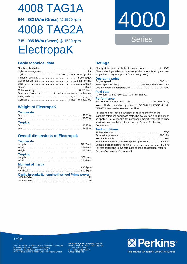
Basic technical data Number of cylinders ... ... ... ... ... ... ... ... ... ... ... ... ... ... ... ... ... .8 Cylinder arrangement .. ... ... ... ... ... ... ... ... ... ... ... ... ... ... In line Cycle ... ... ... ... ... ... ... ... ... ... ... ... 4 stroke, compression ignition Induction system.. ... ... ... ... ... ... ... ... ... ... ... ... ... Turbocharged Compression ratio ... ... ... ... ... ... ... ... ... ... ... ... ... 13.6:1 nominal Bore . ... ... ... ... ... ... ... ... ... ... ... ... ... ... ... ... ... ... ... ... . 160 mm Stroke . ... ... ... ... ... ... ... ... ... ... ... ... ... ... ... ... ... ... ... ..190 mm Cubic capacity . ... ... ... ... ... ... ... ... ... ... ... ... ... ... ... 30.561 litres Direction of rotation.. ... ... ... ... .Anti-clockwise viewed on flywheel Firing order .. ... ... ... ... ... ... ... ... ... ... ... ... ... .1, 4, 7, 6, 8, 5, 2, 3 Cylinder 1. ... ... ... ... ... ... ... ... ... ... ... ... ... furthest from flywheel Weight of ElectropaK Temperate Dry ... ... ... ... ... ... ... ... ... ... ... ... ... ... ... ... ... ... ... ... ... .. 4270 kg Wet .. ... ... ... ... ... ... ... ... ... ... ... ... ... ... ... ... ... ... ... ... .. 4558 kg Tropical Dry ... ... ... ... ... ... ... ... ... ... ... ... ... ... ... ... ... ... ... ... ... .. 4320 kg Wet .. ... ... ... ... ... ... ... ... ... ... ... ... ... ... ... ... ... ... ... ... .. 4618 kg Overall dimensions of Electropak Temperate Length.. ... ... ... ... ... ... ... ... ... ... ... ... ... ... ... ... ... ... ... 3852 mm Width ... ... ... ... ... ... ... ... ... ... ... ... ... ... ... ... ... ... ... ... 2046 mm Height .. ... ... ... ... ... ... ... ... ... ... ... ... ... ... ... ... ... ... ... 2067 mm Tropical Length.. ... ... ... ... ... ... ... ... ... ... ... ... ... ... ... ... ... ... ... 3711 mm Width ... ... ... ... ... ... ... ... ... ... ... ... ... ... ... ... ... ... ... ... 2046 mm Moment of inertia Engine.. ... ... ... ... ... ... ... ... ... ... ... ... ... ... ... ... ... ... ...9.60 kgm² Flywheel... ... ... ... ... ... ... ... ... ... ... ... ... ... ... ... ... ... ...6.02 kgm² Cyclic irregularity, engine/flywheel Prime power 4008TAG1A . ... ... ... ... ... ... ... ... ... ... ... ... ... ... ... ... ... ... ..1.195 4008TAG2A . ... ... ... ... ... ... ... ... ... ... ... ... ... ... ... ... ... ... ..1.180 Ratings Steady state speed stability at constant load ... ... ... ... ... ± 0.25% Electrical rating are based on average alternator efficiency and are for guidance only (0.8 power factor being used). Operating point Engine speed ... ... ... ... ... ... ... ... ... ... ... ... ... ... ... ... .. 1500 rpm Static injection timing ... ... ... ... ... ... ... . See engine number plate Cooling water exit temperature . ... ... ... ... ... ... ... ... ... ... .. < 98°C Fuel data To conform to BS2869 class A2 or BS EN590. Performance Sound pressure level 1500 rpm ... ... ... ... ... ... ... 108 / 109 dB(A) Note: All data based on operation to ISO 3046 / 1, BS 5514 and DIN 6271 standard reference conditions. For engines operating in ambient conditions other than the standard reference conditions stated below a suitable de-rate must be applied. De-rate tables for increased ambient temperature and/ or altitude are available, please contact Perkins Applications Department. Test conditions Air temperature. ... ... ... ... ... ... ... ... ... ... ... ... ... ... ... ... ... . 25°C Barometric pressure.. ... ... ... ... ... ... ... ... ... ... ... ... ... ... 100 kPa Relative humidity... ... ... ... ... ... ... ... ... ... ... ... ... ... ... ... ... . .30% Air inlet restriction at maximum power (nominal) .. ... ... ... . 2.5 kPa Exhaust back pressure (nominal) . ... ... ... ... ... ... ... ... ... . 3.0 kPa For test conditions relevant to data on load acceptance, refer to Perkins Applications Department. 4008 TAG1A 644 - 882 kWm (Gross) @ 1500 rpm 4008 TAG2A 715 - 985 kWm (Gross) @ 1500 rpm ElectropaK 4000 Series All information in this document is substantially correct at time of printing and may be altered subsequently. Publication TSL4252E7 September 2012. Produced in England ©Perkins Engines Company Limited. Perkins Engines Company Limited, Peterborough. PE1 5NA. United Kingdom. Tel: +44 (0)1733 583000. Fax: +44 (0)1733 582240. www.perkins.com 1 of 15

Welcome message from author
This document is posted to help you gain knowledge. Please leave a comment to let me know what you think about it! Share it to your friends and learn new things together.
Transcript
1
4008 TAG1A644 - 882 kWm (Gross) @ 1500 rpm
4008 TAG2A715 - 985 kWm (Gross) @ 1500 rpm
ElectropaK
4000Series
Alof
PrPu
AlofPuPr
1
Basic technical dataNumber of cylinders ... ... ... ... ... ... ... ... ... ... ... ... ... ... ... ... ... .8Cylinder arrangement .. ... ... ... ... ... ... ... ... ... ... ... ... ... ... In lineCycle ... ... ... ... ... ... ... ... ... ... ... ... 4 stroke, compression ignitionInduction system.. ... ... ... ... ... ... ... ... ... ... ... ... ... TurbochargedCompression ratio ... ... ... ... ... ... ... ... ... ... ... ... ... 13.6:1 nominalBore . ... ... ... ... ... ... ... ... ... ... ... ... ... ... ... ... ... ... ... ... . 160 mmStroke . ... ... ... ... ... ... ... ... ... ... ... ... ... ... ... ... ... ... ... ..190 mmCubic capacity . ... ... ... ... ... ... ... ... ... ... ... ... ... ... ... 30.561 litresDirection of rotation.. ... ... ... ... .Anti-clockwise viewed on flywheelFiring order .. ... ... ... ... ... ... ... ... ... ... ... ... ... .1, 4, 7, 6, 8, 5, 2, 3Cylinder 1. ... ... ... ... ... ... ... ... ... ... ... ... ... furthest from flywheel
Weight of ElectropaKTemperate Dry ... ... ... ... ... ... ... ... ... ... ... ... ... ... ... ... ... ... ... ... ... ..4270 kgWet .. ... ... ... ... ... ... ... ... ... ... ... ... ... ... ... ... ... ... ... ... ..4558 kg
Tropical Dry ... ... ... ... ... ... ... ... ... ... ... ... ... ... ... ... ... ... ... ... ... ..4320 kgWet .. ... ... ... ... ... ... ... ... ... ... ... ... ... ... ... ... ... ... ... ... ..4618 kg
Overall dimensions of ElectropakTemperateLength.. ... ... ... ... ... ... ... ... ... ... ... ... ... ... ... ... ... ... ... 3852 mmWidth ... ... ... ... ... ... ... ... ... ... ... ... ... ... ... ... ... ... ... ... 2046 mmHeight .. ... ... ... ... ... ... ... ... ... ... ... ... ... ... ... ... ... ... ... 2067 mm
TropicalLength.. ... ... ... ... ... ... ... ... ... ... ... ... ... ... ... ... ... ... ... 3711 mmWidth ... ... ... ... ... ... ... ... ... ... ... ... ... ... ... ... ... ... ... ... 2046 mm
Moment of inertiaEngine.. ... ... ... ... ... ... ... ... ... ... ... ... ... ... ... ... ... ... ...9.60 kgm²Flywheel... ... ... ... ... ... ... ... ... ... ... ... ... ... ... ... ... ... ...6.02 kgm²
Cyclic irregularity, engine/flywheel Prime power4008TAG1A. ... ... ... ... ... ... ... ... ... ... ... ... ... ... ... ... ... ... ..1.1954008TAG2A. ... ... ... ... ... ... ... ... ... ... ... ... ... ... ... ... ... ... ..1.180
RatingsSteady state speed stability at constant load ... ... ... ... ... ± 0.25%Electrical rating are based on average alternator efficiency and are for guidance only (0.8 power factor being used).
Operating pointEngine speed ... ... ... ... ... ... ... ... ... ... ... ... ... ... ... ... .. 1500 rpmStatic injection timing ... ... ... ... ... ... ... . See engine number plateCooling water exit temperature . ... ... ... ... ... ... ... ... ... ... .. < 98°C
Fuel dataTo conform to BS2869 class A2 or BS EN590.
PerformanceSound pressure level 1500 rpm ... ... ... ... ... ... ... 108 / 109 dB(A)Note: All data based on operation to ISO 3046 / 1, BS 5514 and DIN 6271 standard reference conditions.
For engines operating in ambient conditions other than the standard reference conditions stated below a suitable de-rate must be applied. De-rate tables for increased ambient temperature and/or altitude are available, please contact Perkins Applications Department.
Test conditionsAir temperature. ... ... ... ... ... ... ... ... ... ... ... ... ... ... ... ... ... . 25°CBarometric pressure.. ... ... ... ... ... ... ... ... ... ... ... ... ... ... 100 kPaRelative humidity... ... ... ... ... ... ... ... ... ... ... ... ... ... ... ... ... . .30%Air inlet restriction at maximum power (nominal) .. ... ... ... . 2.5 kPaExhaust back pressure (nominal) . ... ... ... ... ... ... ... ... ... . 3.0 kPaFor test conditions relevant to data on load acceptance, refer to Perkins Applications Department.
of 15
l information in this document is substantially correct at time printing and may be altered subsequently.
oduced in England ©Perkins Engines Company Limited.
Perkins Engines Company LimitedPeterborough PE1 5NA United KingdomTel: +44 (0)1733 583000Fax: +44 (0)1733 582240www.perkins.com
blication No. TPD1747, June 2012
l information in this document is substantially correct at time printing and may be altered subsequently. blication TSL4252E7 September 2012.oduced in England ©Perkins Engines Company Limited.
Perkins Engines Company Limited,Peterborough. PE1 5NA. United Kingdom.Tel: +44 (0)1733 583000.Fax: +44 (0)1733 582240.www.perkins.com
of 15
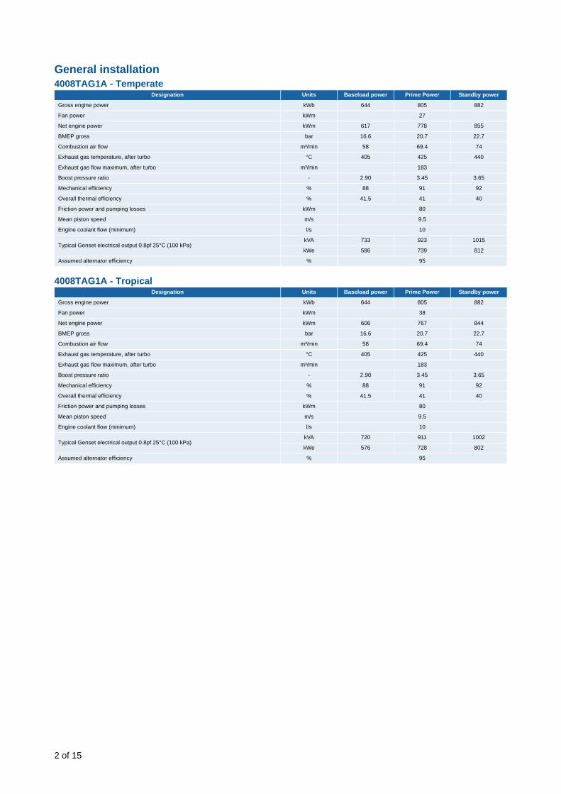
General installation 4008TAG1A - Temperate
4008TAG1A - Tropical
Designation Units Baseload power Prime Power Standby power
Gross engine power kWb 644 805 882
Fan power kWm 27
Net engine power kWm 617 778 855
BMEP gross bar 16.6 20.7 22.7
Combustion air flow m³/min 58 69.4 74
Exhaust gas temperature, after turbo °C 405 425 440
Exhaust gas flow maximum, after turbo m³/min 183
Boost pressure ratio - 2.90 3.45 3.65
Mechanical efficiency % 88 91 92
Overall thermal efficiency % 41.5 41 40
Friction power and pumping losses kWm 80
Mean piston speed m/s 9.5
Engine coolant flow (minimum) l/s 10
Typical Genset electrical output 0.8pf 25°C (100 kPa)kVA 733 923 1015
kWe 586 739 812
Assumed alternator efficiency % 95
Designation Units Baseload power Prime Power Standby power
Gross engine power kWb 644 805 882
Fan power kWm 38
Net engine power kWm 606 767 844
BMEP gross bar 16.6 20.7 22.7
Combustion air flow m³/min 58 69.4 74
Exhaust gas temperature, after turbo °C 405 425 440
Exhaust gas flow maximum, after turbo m³/min 183
Boost pressure ratio - 2.90 3.45 3.65
Mechanical efficiency % 88 91 92
Overall thermal efficiency % 41.5 41 40
Friction power and pumping losses kWm 80
Mean piston speed m/s 9.5
Engine coolant flow (minimum) l/s 10
Typical Genset electrical output 0.8pf 25°C (100 kPa)kVA 720 911 1002
kWe 576 728 802
Assumed alternator efficiency % 95
2 of 15

3
4008TAG2A - Temperate
4008TAG2A - Tropical
Note: Not to be used for CHP design purposes. (Indicative figures only). Consult Perkins Engines Company Limited. Assumes complete combustion.
Rating definitionsBaseload powerUnlimited hours usage with an average load factor of 100% of the published Baseload Power. No overload is permitted on Baseload Power.
Prime powerUnlimited hours usage with an average load factor of 80% of the published Prime Power over each 24 hours period. A 10% overload is available for 1 hour in every 12 hours operation.
Standby powerLimited to 500 hours annual usage with an average load factor of 80% of the published Standby Power rating over each 24 hour period. Up to 300 hours of annual usage may be run continuously. No overload is permitted on Standby Power.
Designation Units Baseload power Prime Power Standby power
Gross engine power kWb 719 899 985
Fan power kWm 27
Net engine power kWm 692 872 958
BMEP gross bar 18.5 23.2 25.4
Combustion air flow m³/min 64 75 80.5
Exhaust gas temperature, after turbo °C 405 438 465
Exhaust gas flow maximum, after turbo m³/min 200
Boost pressure ratio - 3.18 3.70 4,0
Mechanical efficiency % 90 92 92
Overall thermal efficiency % 41.5 41 40
Friction power and pumping losses kWm 80
Mean piston speed m/s 9.5
Engine coolant flow (minimum) l/s 10,0
Typical Genset electrical output 0.8pf 25°C (100 kPa)kVA 821 1035 1138
kWe 657 828 910
Assumed alternator efficiency % 95
Designation Units Baseload power Prime Power Standby power
Gross engine power kWb 719 899 985
Fan power kWm 38
Net engine power kWm 681 861 947
BMEP gross bar 18.5 23.2 25.4
Combustion air flow m³/min 64 75 80.5
Exhaust gas temperature, after turbo °C 405 438 465
Exhaust gas flow maximum, after turbo m³/min 200
Boost pressure ratio - 3.18 3.70 4,0
Mechanical efficiency % 90 92 92
Overall thermal efficiency % 41.5 41 40
Friction power and pumping losses kWm 80
Mean piston speed m/s 9.5
Engine coolant flow (minimum) l/s 10,0
Typical Genset electrical output 0.8pf 25°C (100 kPa)kVA 809 1022 1125
kWe 647 818 900
Assumed alternator efficiency % 95
of 15

Energy balanceNote: Not to be used for CHP design purposes. (Indicative figures only). Consult Perkins Engines Company Limited. Assumes complete combustion.
4008TAG1A - Tropical
4008TAG1A - Temperate
4008TAG2A - Tropical
4008TAG2A - Temperate
Designation Units Baseload power Prime power Standby power
Energy in fuel kWt 1544 1957 2191
Energy in power output (gross) kWb 644 805 882
Energy to cooling fan kWm 38 38 38
Energy in power output (net) kWm 606 767 844
Energy to exhaust kWt 492 606 712
Energy to coolant and oil kWt 245 300 313
Energy to radiation kWt 30 70 91
Energy to charge coolers kWt 133 176 193
Designation Units Baseload power Prime power Standby power
Energy in fuel kWt 1544 1957 2191
Energy in power output (gross) kWb 644 805 882
Energy to cooling fan kWm 27 27 27
Energy in power output (net) kWm 617 778 855
Energy to exhaust kWt 492 606 712
Energy to coolant and oil kWt 245 300 313
Energy to radiation kWt 30 70 91
Energy to charge coolers kWt 133 176 193
Designation Units Baseload power Prime power Standby power
Energy in fuel kWt 1733 2209 2498
Energy in power output (gross) kWb 719 899 985
Energy to cooling fan kWm 38 38 38
Energy in power output (net) kWm 681 861 947
Energy to exhaust kWt 548 698 807
Energy to coolant and oil kWt 273 332 349
Energy to radiation kWt 40 80 100
Energy to charge coolers kWt 153 200 257
Designation Units Baseload power Prime power Standby power
Energy in fuel kWt 1733 2209 2498
Energy in power output (gross) kWb 719 899 985
Energy to cooling fan kWm 27 27 27
Energy in power output (net) kWm 692 872 958
Energy to exhaust kWt 548 698 807
Energy to coolant and oil kWt 273 332 349
Energy to radiation kWt 40 80 100
Energy to charge coolers kWt 153 200 257
4 of 15
5
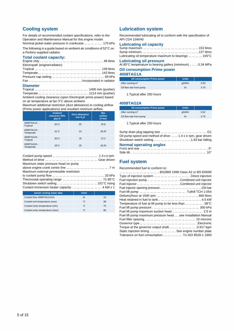
Cooling systemFor details of recommended coolant specifications, refer to the Operation and Maintenance Manual for this engine model.Nominal jacket water pressure in crankcase ... ... ... ... ... . 170 kPaThe following is a guide based on ambient air conditions of 52°C on a Perkins supplied radiator.
Total coolant capacity:Engine only.. ... ... ... ... ... ... ... ... ... ... ... ... ... ... ... ... ... .. 48 litresElectropaK (engine/radiator):Tropical ... ... ... ... ... ... ... ... ... ... ... ... ... ... ... ... ... ... ... 149 litresTemperate ... ... ... ... ... ... ... ... ... ... ... ... ... ... ... ... ... ... 143 litresPressure cap setting ... ... ... ... ... ... ... ... ... ... ... ... ... ... ... 69 kPaFan .. ... ... ... ... ... ... ... ... ... ... ... ... ... ... ..Incorporated in radiator
DiameterTropical ... ... ... ... ... ... ... ... ... ... ... ... ... ... ... . 1400 mm (pusher)Temperate ... ... ... ... ... ... ... ... ... ... ... ... ... ... . 1214 mm (pusher)Ambient cooling clearance (open ElectropaK prime power) based on air temperature at fan 3°C above ambient.Maximum additional restriction (duct allowance) to cooling airflow (Prime power applications) and resultant minimum airflow.
Coolant pump speed ... ... ... ... ... ... ... ... ... ... ... ... ... .1.4 x e rpm Method of drive ... ... ... ... ... ... ... ... ... ... ... ... ... ... ... Gear drivenMaximum static pressure head on pump above engine crank centre line ... ... ... ... ... ... ... ... ... ... ... ... .7 mMaximum external permissible restriction to coolant pump flow ... ... ... ... ... ... ... ... ... ... ... ... ... ... ... 20 kPaThermostat operating range ... ... ... ... ... ... ... ... ... ... ... . 71-85°CShutdown switch setting .. ... ... ... ... ... ... ... ... ... ... ... 101°C risingCoolant immersion heater capacity . ... ... ... ... ... ... ... ... .4 kW x 1
Lubrication systemRecommended lubricating oil to conform with the specification of API CG4 15W/40
Lubricating oil capacitySump maximum ... ... ... ... ... ... ... ... ... ... ... ... ... ... ... ...153 litresSump minimum. ... ... ... ... ... ... ... ... ... ... ... ... ... ... ... ...127 litresLubricating oil temperature maximum to bearings ... ... ... ... 105°C
Lubricating oil pressureAt 80°C temperature to bearing gallery (minimum) .. ... .. 0.34 MPa
Oil consumption Prime power4008TAG1A
4008TAG2A
Sump drain plug tapping size ... ... ... ... ... ... ... ... ... ... ... ... ... .G1Oil pump speed and method of drive ... ... 1.4 x e rpm, gear drivenShutdown switch setting ... ... ... ... ... ... ... ... ... ... ..1.93 bar falling
Normal operating anglesFront and rear ... ... ... ... ... ... ... ... ... ... ... ... ... ... ... ... ... ... ... ..5°Side tilt .. ... ... ... ... ... ... ... ... ... ... ... ... ... ... ... ... ... ... ... ... ... 10°
Fuel systemRecommended fuel to conform to:.. ... ... ... ... ... ... ... ... ... ... .. BS2869 1998 Class A2 or BS EN590Type of injection system ... ... ... ... ... ... ... ... ... ... ..Direct injectionFuel injection pump... ... ... ... ... ... ... ... ... ..Combined unit injectorFuel injector .. ... ... ... ... ... ... ... ... ... ... ... ..Combined unit injectorFuel injector opening pressure .. ... ... ... ... ... ... ... ... ... ... ... .. 234 barFuel lift pump ... ... ... ... ... ... ... ... ... ... ... ... ... . Tuthill TCH 1-054Delivery/hour at 1500 rpm. ... ... ... ... ... ... ... ... ... ... ... ...660 litresHeat retained in fuel to tank .. ... ... ... ... ... ... ... ... ... ... ... .. 4.5 kWTemperature of fuel at lift pump to be less than ... ... ... ... ... . 58°CFuel lift pump pressure . ... ... ... ... ... ... ... ... ... ... ... ... ... 300 kPaFuel lift pump maximum suction head .. ... ... ... ... ... ... ... ... 2.5 mFuel lift pump maximum pressure head ... .see Installation ManualFuel filter spacing.. ... ... ... ... ... ... ... ... ... ... ... ... ... ... 10 micronsGovernor type ... ... ... ... ... ... ... ... ... ... ... ... ... ... ... ... ..ElectronicTorque at the governor output shaft.. ... ... ... ... ... ... ... .0.917 kgmStatic injection timing ... ... ... ... ... ... ... . See engine number plateTolerance on fuel consumption. ... ... ... ... ... .To ISO 8528-1 1993
Ambient clearance 50%
glycol
Duct allowance mm H20
Minairflow m³/sec
4008TAG1A - Tropical 50°C 20 20.8
4008TAG1A - Temperate 41°C 24 18.25
4008TAG2A - Tropical 50°C 18 22.5
4008TAG2A - Temperate 35°C 25 18.25
Jacket cooling water data Units
Coolant flow 4008TAG1A/2A l/s 10
Coolant exit temperature (max) °C 98
Coolant entry temperature (min) °C 70
Coolant entry temperature (max) °C 86
Oil consumption Prime power Units
After running-in1
1.Typical after 250 hours
g/kWhr 0.50
Oil flow rate from pump l/s 3.70
Oil consumption Prime power Units
After running-in1
1.Typical after 250 hours
g/kWhr 0.52
Oil flow rate from pump l/s 3.70
of 15
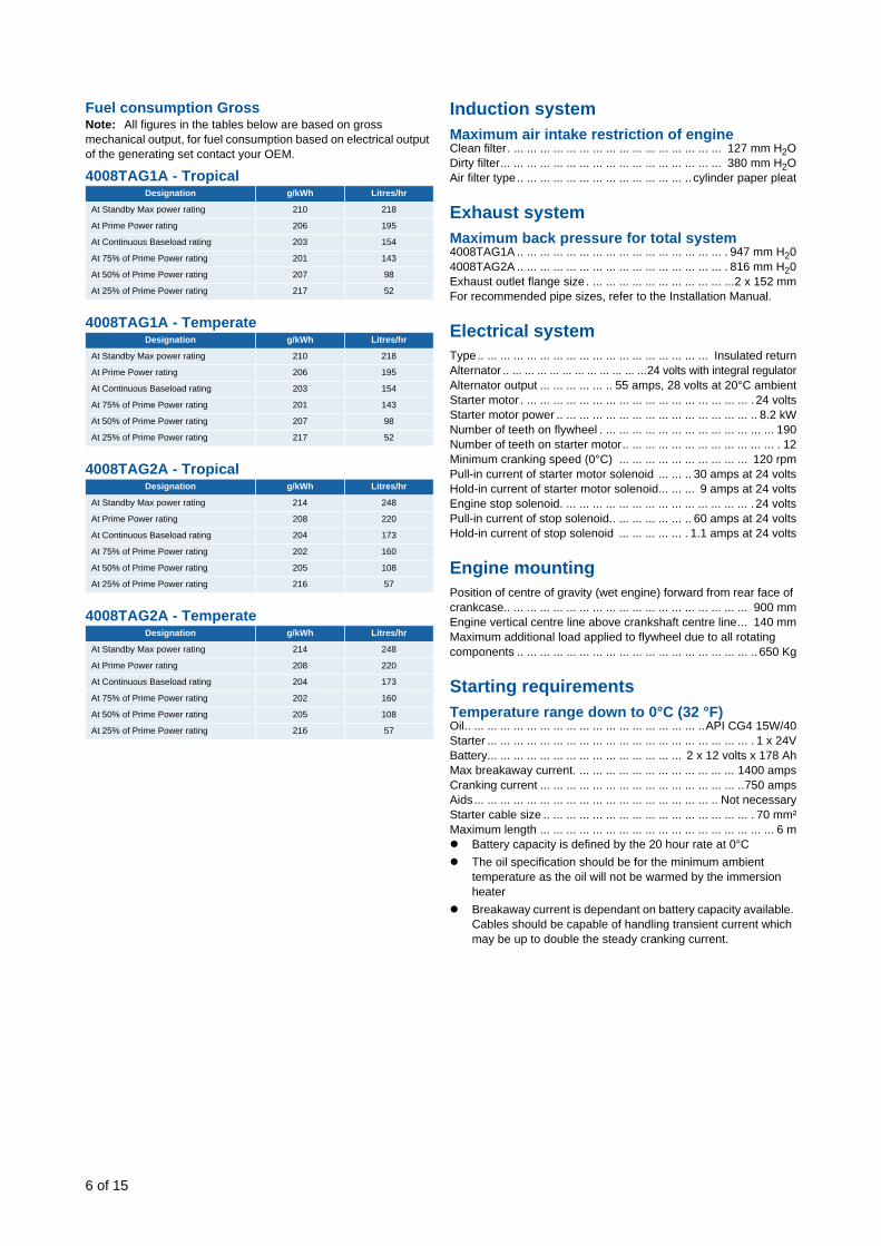
Fuel consumption GrossNote: All figures in the tables below are based on gross mechanical output, for fuel consumption based on electrical output of the generating set contact your OEM.
4008TAG1A - Tropical
4008TAG1A - Temperate
4008TAG2A - Tropical
4008TAG2A - Temperate
Induction systemMaximum air intake restriction of engineClean filter. ... ... ... ... ... ... ... ... ... ... ... ... ... ... ... ... 127 mm H2ODirty filter... ... ... ... ... ... ... ... ... ... ... ... ... ... ... ... ... 380 mm H2OAir filter type .. ... ... ... ... ... ... ... ... ... ... ... ... .. cylinder paper pleat
Exhaust systemMaximum back pressure for total system4008TAG1A .. ... ... ... ... ... ... ... ... ... ... ... ... ... ... ... . 947 mm H204008TAG2A .. ... ... ... ... ... ... ... ... ... ... ... ... ... ... ... . 816 mm H20Exhaust outlet flange size . ... ... ... ... ... ... ... ... ... ... ...2 x 152 mmFor recommended pipe sizes, refer to the Installation Manual.
Electrical systemType.. ... ... ... ... ... ... ... ... ... ... ... ... ... ... ... ... ... Insulated returnAlternator .. ... ... ... ... ... ... ... ... ... ... ...24 volts with integral regulatorAlternator output ... ... ... ... ... .. 55 amps, 28 volts at 20°C ambientStarter motor . ... ... ... ... ... ... ... ... ... ... ... ... ... ... ... ... ... . 24 voltsStarter motor power .. ... ... ... ... ... ... ... ... ... ... ... ... ... ... .. 8.2 kWNumber of teeth on flywheel . ... ... ... ... ... ... ... ... ... ... ... ... ... 190Number of teeth on starter motor.. ... ... ... ... ... ... ... ... ... ... ... . 12Minimum cranking speed (0°C) ... ... ... ... ... ... ... ... ... ... 120 rpmPull-in current of starter motor solenoid ... ... .. 30 amps at 24 voltsHold-in current of starter motor solenoid... ... ... 9 amps at 24 voltsEngine stop solenoid. ... ... ... ... ... ... ... ... ... ... ... ... ... ... . 24 voltsPull-in current of stop solenoid.. ... ... ... ... ... .. 60 amps at 24 voltsHold-in current of stop solenoid ... ... ... ... ... . 1.1 amps at 24 volts
Engine mountingPosition of centre of gravity (wet engine) forward from rear face of crankcase.. ... ... ... ... ... ... ... ... ... ... ... ... ... ... ... ... ... ... 900 mmEngine vertical centre line above crankshaft centre line... 140 mmMaximum additional load applied to flywheel due to all rotating components .. ... ... ... ... ... ... ... ... ... ... ... ... ... ... ... ... ... .. 650 Kg
Starting requirementsTemperature range down to 0°C (32 °F)Oil.. ... ... ... ... ... ... ... ... ... ... ... ... ... ... ... ... ... ..API CG4 15W/40Starter ... ... ... ... ... ... ... ... ... ... ... ... ... ... ... ... ... ... ... ... . 1 x 24VBattery... ... ... ... ... ... ... ... ... ... ... ... ... ... ... 2 x 12 volts x 178 AhMax breakaway current. ... ... ... ... ... ... ... ... ... ... ... ... 1400 ampsCranking current ... ... ... ... ... ... ... ... ... ... ... ... ... ... ... ..750 ampsAids ... ... ... ... ... ... ... ... ... ... ... ... ... ... ... ... ... ... .. Not necessaryStarter cable size .. ... ... ... ... ... ... ... ... ... ... ... ... ... ... ... . 70 mm²Maximum length ... ... ... ... ... ... ... ... ... ... ... ... ... ... ... ... ... ... 6 m
Battery capacity is defined by the 20 hour rate at 0°CThe oil specification should be for the minimum ambient temperature as the oil will not be warmed by the immersion heaterBreakaway current is dependant on battery capacity available. Cables should be capable of handling transient current which may be up to double the steady cranking current.
Designation g/kWh Litres/hr
At Standby Max power rating 210 218
At Prime Power rating 206 195
At Continuous Baseload rating 203 154
At 75% of Prime Power rating 201 143
At 50% of Prime Power rating 207 98
At 25% of Prime Power rating 217 52
Designation g/kWh Litres/hr
At Standby Max power rating 210 218
At Prime Power rating 206 195
At Continuous Baseload rating 203 154
At 75% of Prime Power rating 201 143
At 50% of Prime Power rating 207 98
At 25% of Prime Power rating 217 52
Designation g/kWh Litres/hr
At Standby Max power rating 214 248
At Prime Power rating 208 220
At Continuous Baseload rating 204 173
At 75% of Prime Power rating 202 160
At 50% of Prime Power rating 205 108
At 25% of Prime Power rating 216 57
Designation g/kWh Litres/hr
At Standby Max power rating 214 248
At Prime Power rating 208 220
At Continuous Baseload rating 204 173
At 75% of Prime Power rating 202 160
At 50% of Prime Power rating 205 108
At 25% of Prime Power rating 216 57
6 of 15
7
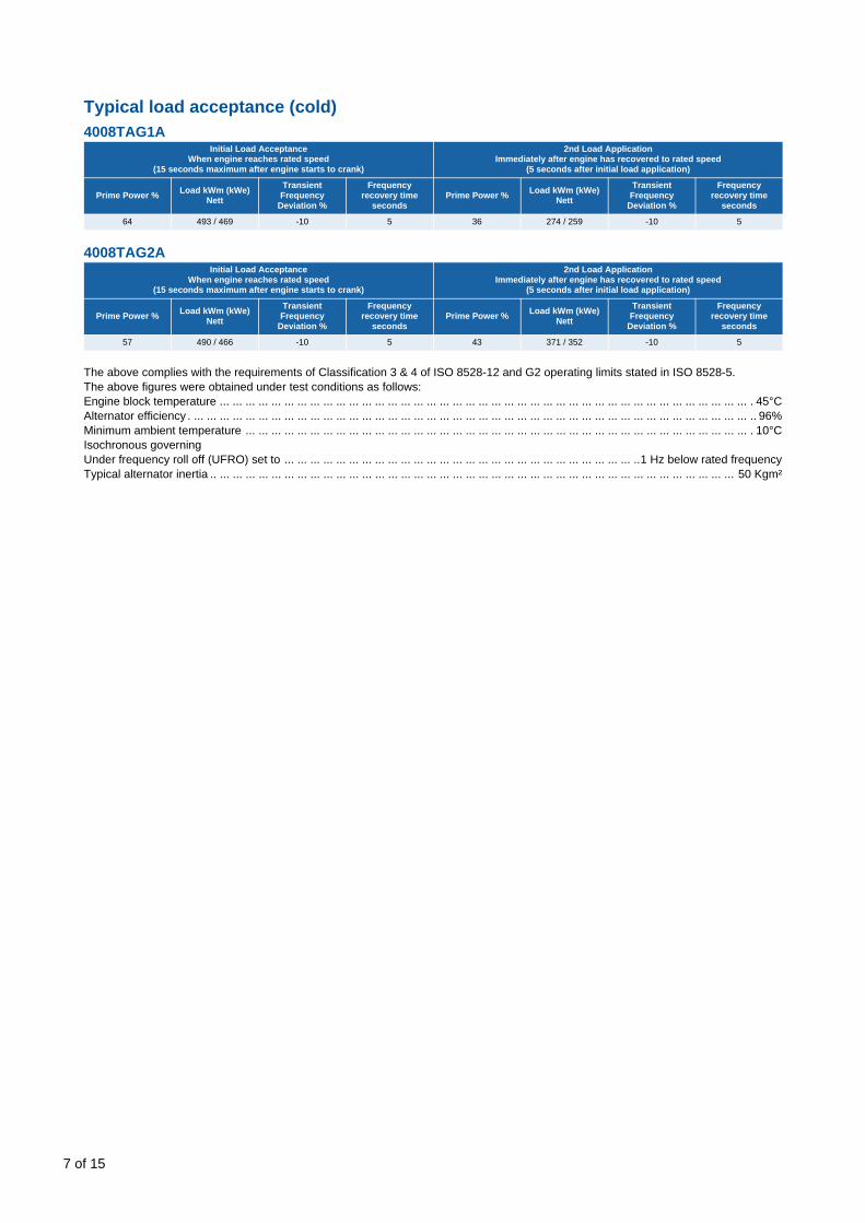
Typical load acceptance (cold)4008TAG1A
4008TAG2A
The above complies with the requirements of Classification 3 & 4 of ISO 8528-12 and G2 operating limits stated in ISO 8528-5.The above figures were obtained under test conditions as follows:Engine block temperature ... ... ... ... ... ... ... ... ... ... ... ... ... ... ... ... ... ... ... ... ... ... ... ... ... ... ... ... ... ... ... ... ... ... ... ... ... ... ... ... ... . 45°CAlternator efficiency . ... ... ... ... ... ... ... ... ... ... ... ... ... ... ... ... ... ... ... ... ... ... ... ... ... ... ... ... ... ... ... ... ... ... ... ... ... ... ... ... ... ... ... .. 96%Minimum ambient temperature ... ... ... ... ... ... ... ... ... ... ... ... ... ... ... ... ... ... ... ... ... ... ... ... ... ... ... ... ... ... ... ... ... ... ... ... ... ... ... . 10°CIsochronous governingUnder frequency roll off (UFRO) set to ... ... ... ... ... ... ... ... ... ... ... ... ... ... ... ... ... ... ... ... ... ... ... ... ... ... ... ..1 Hz below rated frequencyTypical alternator inertia .. ... ... ... ... ... ... ... ... ... ... ... ... ... ... ... ... ... ... ... ... ... ... ... ... ... ... ... ... ... ... ... ... ... ... ... ... ... ... ... ... 50 Kgm²
Initial Load Acceptance When engine reaches rated speed
(15 seconds maximum after engine starts to crank)
2nd Load ApplicationImmediately after engine has recovered to rated speed
(5 seconds after initial load application)
Prime Power % Load kWm (kWe) Nett
Transient Frequency
Deviation %
Frequency recovery time
secondsPrime Power % Load kWm (kWe)
Nett
Transient Frequency
Deviation %
Frequency recovery time
seconds
64 493 / 469 -10 5 36 274 / 259 -10 5
Initial Load Acceptance When engine reaches rated speed
(15 seconds maximum after engine starts to crank)
2nd Load ApplicationImmediately after engine has recovered to rated speed
(5 seconds after initial load application)
Prime Power % Load kWm (kWe) Nett
Transient Frequency
Deviation %
Frequency recovery time
secondsPrime Power % Load kWm (kWe)
Nett
Transient Frequency
Deviation %
Frequency recovery time
seconds
57 490 / 466 -10 5 43 371 / 352 -10 5
of 15

Noise dataNoise levelsThe figures for total noise levels are typical for an engine running at Prime power rating in a semi-reverberant environment and measured at a distance of one metre from the periphery of the engine.
Octave analysisThe following histograms show an octave band analysis at the position of the maximum noise level.
Total noise levelSound pressure level re: -20 x paSpeed 1500 rpm... ... ... ... ... ... ... ... ... ... ... ... ... ... ... ... ... ... ... ... ... ... ... ... ... ... ... ... ... ... . Ambient noise level 79 dB(A) 4008TAG1A
Octave analysis performed at the position of maximum noise4008TAG1A / 4008TAG2A
Isochronous governingUnder frequency roll off (UFRO) set to ... ... ... ... ... ... ... ... ... ... ... ... ... ... ... ... ... ... ... ... ... ... ... ... ... ... ... ..1 Hz below rated frequencyTypical alternator inertia . ... ... ... ... ... ... ... ... ... ... ... ... ... ... ... ... ... ... ... ... ... ... ... ... ... ... ... ... ... ... ... ... ... ... ... ... ... ... ... ... 20 kgm²All tests were conducted using an engine installed and serviced to Perkins Engines Company Limited recommendations.The information given on this Technical Data Sheet is for standard engines, and for guidance only. For ratings other than shown contact the Applications department.
10 6–
4008TAG1A - Temperate 4008TAG2A - Temperate
Position 7108 - dBA109 - dBA
4008TAG1A4008TAG2A
Position 6108 - dBA109 - dBA
4008TAG1A4008TAG2A
Position 5107 - dBA108 - dBA
4008TAG1A4008TAG2A
Position 2108 - dBA109 - dBA
4008TAG1A4008TAG2A
Position 3108 - dBA109 - dBA
4008TAG1A4008TAG2A
Position 4107 - dBA108 - dBA
4008TAG1A4008TAG2A
F
R
120
110
100
90
80
70
60 31.5 63 125 250 500 1K 2K 4K 8K 16K Hz
1500 rev/min at position 7120
110
100
90
80
70
60 31.5 63 125 250 500 1K 2K 4K 8K 16K Hz
1500 rev/min at position 7
Noi
se le
vel -
dB
Noi
se le
vel -
dB
110 - dBA110 - dBA
4008TAG1A4008TAG2A
4008TAG1A4008TAG2A
109 - dBA110 - dBA
4008TAG1A4008TAG2A
107 - dBA109 - dBA
109 - dBA109 - dBA
109 - dBA110 - dBA
108 - dBA108 - dBA
4008TAG1A4008TAG2A
4008TAG1A4008TAG2A
4008TAG1A4008TAG2A
Temperate
Tropical
Temperate
Tropical
Temperate
Tropical
Temperate
Tropical
Temperate
Tropical
Temperate
Tropical
Position 1103 - dBA104 - dBA
4008TAG1A4008TAG2A
105 - dBA105 - dBA
4008TAG1A4008TAG2A
Temperate
Tropical
8 of 15

9
4008TAG1A and 4008TAG2A - Left hand side (Tropical)
1125
1035
1726
.5
17.5
220
70
340
17.5
3711
OV
ER
ALL
LEN
GTH
1343
C O
F G
WE
TW
ITH
FU
EL
CO
OLE
R13
40 C
OF
GW
ITH
OU
T FU
EL
CO
OLE
R
25
297
486.
5
1076
.5
2
5
1195
TED
DIN
GTO
N L
.O.P
./H.W
.T.
PR
OTE
CTI
ON
SW
ITC
H
Ø 5
08 (2
0") T
OR
SIO
NA
LV
IBR
ATI
ON
DAM
PE
R
FRO
NT
LIFT
ING
BR
AC
KE
T(E
NG
INE
ON
LY)
RO
CKE
R C
OV
ER
S
EXP
AN
SIO
N B
ELLO
WS
ON
OF
CR
ANK
SH
AFT
WA
TER
RA
IL
EXH
AUS
T M
ANIF
OLD
S
AIR
INLE
T
AIR
INLE
T
REAR FACE OF CRANKCASE
FRONT FACE OF C/CASE
OIL
FEE
D P
IPE
TO
TUR
BOC
HA
RG
ERS
CR
AN
KCA
SE
INP
EC
TIO
NC
OV
ER
S
FIR
ST
GR
OO
VE
ON
PU
LLE
Y
CR
AN
KS
HAF
T P
ULL
EY
4 G
RO
OV
EFO
R S
PB
BEL
T SE
CTI
ON
19
CEN
TRES
FA
N
of 15

4008TAG1A and 4008TAG2A - Front (Tropical)
517
164
735
165
572
21
65
376.
5
7 P
ITC
HE
SO
F 20
0=
1400
OV
ERM
ATR
IX
1592
206
OVE
R M
ATR
IX19
44
650
972
996
1992
385
Rp
1/2
TAP
PIN
G IN
THE
RM
OST
AT F
RO
NT
Rp
1/2
AN
D R
3/8
TA
PPI
NG
SIN
TH
ERM
OS
TAT
SID
E
G 3
/4 W
ATE
R D
RA
IN P
LUG
0.7
BA
R R
ELI
EF
VA
LVE
RA
DIA
TOR
FIL
LER
CA
P
LEV
ER
SH
OW
N IN
STO
P P
OSI
TIO
N
(STO
P P
OSI
TIO
N)
DE
-EN
ER
GIS
ED
PO
SIT
ION
TO R
UN
, SH
OW
N IN
24V
SOLE
NO
ID E
NE
RG
ISE
D
FUE
L LE
AK
-OFF
CO
NN
: TO
SU
IT
15m
m O
/D P
IPE
'BIT
E' T
YP
EN
ON
-RET
UR
N V
ALV
E S
UP
PLIE
D.
RE
TUR
N H
EA
D 1
8 M
ETR
ES
MA
X
FILL
ER
TU
BE
LUB
OIL
FUE
L IN
LET
CO
NN
TO
SU
IT ø
15m
m P
IPE
MA
XIM
UM
LIF
T 2.
5 M
ETR
ES
.W
HEN
FU
EL
TAN
K O
UTL
ET IS
LO
WER
TH
AN
P
UM
P IN
LET,
A N
ON
-RE
TUR
N V
ALV
E M
US
TBE
FIT
TED
TO
TA
NK
SU
MP
DR
AIN
PLU
G
CLE
AR
ANC
ER
EQ
UIR
ED
TO R
EM
OVE
SU
MP
CR
AN
KC
AS
E B
RE
ATH
ER
S
UP
PLIE
D W
ITH
FLE
XIB
LE H
OS
E 86
5 LO
NG
Ø 5
1 I/D
16 S
LOTS
11
X 1
9 FR
ON
T D
UC
TIN
G F
ACE
OF
CR
AN
KS
HA
FT
G1/
2 C
ON
DE
NS
ATE
PLU
GW
ITH
3m
m H
OLE
TH
RU
'IN
BO
TTO
M O
F A
IR T
ANK
10 of 15

11
4008TAG1A and 4008TAG2A - Right hand side (Tropical)
19.5
182
1726
.5
40.5
697.
5
87
248.
5
444
EN
GIN
E T
ER
MIN
ALB
OX
HEI
NZM
AN
N C
ON
TRO
LBO
X
24V
STA
RTE
R
STA
RTE
R R
ELA
Y
TWIN
AIR
FIL
TER
S18
00 C
.F.M
EA
CH
OIL
C
OO
LER
AIR
INLE
TM
ANIF
OLD
S
FUE
L LI
FTP
UM
P
24V
ALT
ER
NA
TOR
AIR
INLE
T
2 x
3/8-
18 N
PS
FTA
PP
ING
S
TRIP
LE L
UB
OIL
FILT
ER
S
AIR
INLE
T
1/8-
27 N
PS
F TA
PPI
NG
FOR
LU
B. O
IL P
RE
SS.
CO
NN
.
G 3
/8 T
APP
ING
FOR
LU
B. O
IL
TEM
P. C
ON
N.
HEI
NZM
AN
N E
6G
OV
ER
NO
R/A
CTU
ATO
R
FRONT FACE OF C/CASE
REAR FACE OF C/CASE
LUB
OIL
PU
MP
MED
IUM
DU
TY
FUE
L FI
LTER
/SEP
AR
ATO
R
LUB
OIL
DIP
STI
CK
FUE
L H
AN
D P
RIM
ING
PU
MP
SU
MP
DR
AIN
PLU
G
G 1
(BO
TH S
IDE
S)
FLO
AT
SW
ITC
H
G3/
4 FU
EL
CO
OLE
RC
ON
NEC
TIO
NS
of 15

4008TAG1A and 4008TAG2A - Rear (Tropical)
11.2
5°
25
549
406.
4
2046
OV
ER
ALL
WID
TH
645
786
OVE
RA
LLH
EIG
HT
2145
.5
EQ
UA
LLY
SP
AC
ED A
S SH
OW
N O
NØ
679
.45
(26.
75")
EQU
ALL
Y S
PAC
ED O
N
Ø 5
42.9
3 (2
1.37
5") P
C
16 H
OLE
S M
12 X
21
DE
EP
AIR
FIL
TER
S B
EFO
RE
NO
T IN
US
E (R
EM
OV
EB
E R
EMO
VE
D W
HE
NE
NG
INE
ON
LY, M
AY
LIFT
ING
BR
ACK
ETS
Ø 3
0 H
OLE
(LIF
TIN
G)
EX
ERTE
D O
N T
UR
BO
CH
ARG
ER
SE
NS
UR
E T
HA
T N
O L
OA
D IS
AD
EQ
UA
TELY
SU
PPO
RTE
D T
OS
YST
EM
PIP
EW
OR
K M
US
T B
EFL
AN
GE
DET
AILS
SE
E R
IGH
T,E
XH
AUST
OU
TLE
T EL
BO
WS
,FO
R
FOR
ELE
ME
NT
REM
OV
AL
AIR
CLE
AN
ER R
EST
RIC
TIO
NIN
DIC
ATO
RS
'A'
RO
TATI
ON
OF CYLSU
SIN
G)
6 H
OLE
S M
16 X
30
DE
EP
12 of 15

13
4008TAG1A and 4008TAG2A - Left hand side (Temperate)
1125
1035
1726
.5
17.5
220
70
340
Ø22
8.6
17.5
265.
4
5
297
1316
C O
F G
WE
TW
ITH
FU
EL
CO
OLE
R13
13 C
OF
G W
ETW
ITH
OU
T FU
EL C
OO
LER
3852
OV
ERA
LL L
ENG
TH
1335
25
926.
5
TED
DIN
GTO
N L
.O.P
./H.W
.T.
PR
OTE
CTI
ON
SW
ITC
H
Ø 5
08 (2
0") T
OR
SIO
NA
LVI
BR
ATIO
N D
AM
PER
FRO
NT
LIFT
ING
BR
AC
KE
T(E
NG
INE
ON
LY)
RO
CKE
R C
OV
ER
S
EXP
AN
SIO
N B
ELLO
WS
ON
OF
CR
ANK
SH
AFT
WA
TER
RA
IL
EXH
AU
ST
MA
NIF
OLD
S
AIR
INLE
T
AIR
INLE
T
REAR FACE OF CRANKCASE
FRONT FACE OF CRANKCASEO
IL F
EED
PIP
E TO
TUR
BO
CH
ARG
ER
S
CR
AN
KC
ASE
INP
ECTI
ON
CO
VER
S F
AN
FIR
ST G
RO
OV
E O
N P
ULL
EY
CR
AN
KSH
AFT
PU
LLE
Y 4
GR
OO
VE
FOR
SPB
BE
LT S
EC
TIO
N 1
9 C
EN
TRE
S
of 15

4008TAG1A and 4008TAG2A - Front (Temperate)
517
164
735
21
6557
2
650
15
1292
OV
ER
M
ATR
IX
385
324
3 P
ITC
HES
OF
180
= 54
0
125
3 P
ITC
HES
OF
180
= 54
0
1992
OV
ER
MA
TRIX
1942
Rp
1/2
TAP
PIN
G IN
THE
RM
OST
AT
FRO
NT
Rp
1/2
AN
D R
3/8
TAP
PIN
GS
IN T
HE
RM
OS
TAT
SID
E
G 3
/4 W
ATE
R D
RAI
N P
LUG
0.7
BAR
RE
LIEF
VAL
VE
RA
DIA
TOR
FIL
LER
CAP
LEV
ER S
HO
WN
INST
OP
PO
SITI
ON
(STO
P P
OS
ITIO
N)
DE
-EN
ERG
ISE
D P
OSI
TIO
NTO
RU
N, S
HO
WN
IN24
V S
OLE
NO
ID E
NE
RG
ISED
FUE
L LE
AK
-OFF
CO
NN
: TO
SU
IT
15m
m O
/D P
IPE
'BIT
E' T
YP
EN
ON
-RE
TUR
N V
ALV
E S
UP
PLIE
D.
RE
TUR
N H
EAD
18
MET
RES
MA
X
FILL
ER
TU
BELU
B O
IL
FUE
L IN
LET
CO
NN
TO
SU
IT Ø
15m
m P
IPE
MA
XIM
UM
LIF
T 2.
5 M
ETR
ES.
WH
EN
FU
EL
TAN
K O
UTL
ET
IS L
OW
ER
TH
AN
P
UM
P IN
LET,
A N
ON
-RET
UR
N V
ALV
E M
US
TB
E F
ITTE
D T
O T
AN
K
SU
MP
DR
AIN
PLU
G
CLE
AR
AN
CE
REQ
UIR
EDTO
REM
OV
ES
UM
P
CR
AN
KC
ASE
BR
EA
THE
R
SU
PPL
IED
WIT
H
FLE
XIB
LE H
OS
E 8
65LO
NG
x Ø
51
I/D
16 H
OLE
S Ø
11
FRO
NT
DU
CTI
NG
FAC
E
G 1
/2 C
ON
DE
NS
ATE
DR
AIN
PLU
G W
ITH
3m
m H
OLE
TH
RO
'IN
BO
TTO
M O
F A
IR T
ANK
14 of 15

4008TAG1A and 4008TAG2A - Right hand side (Temperate)
19.5
182
1726
.5
40.5
697.
5
924
248.
584
447
92.3
EN
GIN
E T
ER
MIN
ALB
OX
HE
INZM
AN
N C
ON
TRO
LB
OX
24V
STAR
TER
STA
RTE
R R
ELA
Y
TWIN
AIR
FIL
TER
S18
00 C
.F.M
EA
CH
OIL
C
OO
LER
AIR
INLE
TM
AN
IFO
LDS
FUEL
LIF
TP
UM
P
24V
ALT
ER
NA
TOR
OF
CR
AN
KSH
AFT
AIR
INLE
T
2 x
3/8-
18 N
PSF
TAP
PIN
GS
TRIP
LE L
UB
OIL
FILT
ER
S
AIR
INLE
T
1/8-
27 N
PSF
TAP
PIN
GFO
R L
UB
. OIL
PR
ES
S.
CO
NN
.
G 3
/8 T
AP
PIN
GFO
R L
UB
. OIL
TE
MP
. CO
NN
.
HE
INZM
AN
N E
6G
OV
ER
NO
R/A
CTU
ATO
R
FRONT FACE OF C/CASE
REAR FACE OF C/CASE
LUB
OIL
PU
MP
MED
IUM
DU
TY
FUE
L FI
LTE
R/S
EP
ARAT
OR
LUB
OIL
DIP
STI
CK
FUE
L H
AND
PR
IMIN
G P
UM
P
SUM
P D
RAI
N P
LUG
G
1 (B
OTH
SID
ES)
FLO
AT
SW
ITC
H
G3/
4 FU
EL
CO
OLE
RC
ON
NE
CTI
ON
S.
15 of 15
Related Documents