Basics of Service – 4-WHEEL DRIVE EIFM – Pub1.0/ April’07 1 FOUR WHEEL DRIVE – FT 60, 70 & 80 1. INTRODUCTION There are almost as many different types of four-wheel-drive systems as there are four-wheel-drive vehicles. Four wheel drive are classified into two types. One is “4 wheel drive – Part time”, another one is “4 wheel drive – Full time” or also known as “All wheel drive”. Purpose of four wheel drive in tractor is to transmit the power from the engine to the wheels and to allow: • Increasing of tractive force, reducing the number of revolutions. • Adjusting of inner wheels’ speed with outer wheels’ speed during steering. “4 wheel drive - part time” systems are designed in such a way, only rear wheel gets the power from transmission and the four wheel drive will be in neutral condition. When the tractor stuck some where in the slippery area or climbing in hilly area, four wheel drive comes to alive by engaging the system through transfer box. These systems are meant only for use in low-traction conditions, such as off-road or on snow or ice. But, in “4 wheel drive - full time” system, both front & rear wheels are always engaged together and get the power from transmission through transfer box. All-wheel-drive systems are designed to function on all types of surfaces, both on- and off-road, and most of them cannot be switched off. Farmtrac 60, 70 & 80 tractors are fitted with “Four wheel drive–Part time” system. But, the design parameters are different as compare to FT 60 and FT 70 systems. FT 70 and FT 80 are fitted with same design of front axle. The front wheels installed on the any front axle system to be maintain a certain angle in accordance with the front wheel alignment. That already discussed in chapter 1 (Ref. page no.1) FT 60 – 4 Wheel Drive

Welcome message from author
This document is posted to help you gain knowledge. Please leave a comment to let me know what you think about it! Share it to your friends and learn new things together.
Transcript

Basics of Service – 4-WHEEL DRIVE
EIFM – Pub1.0/ April’07 1
FOUR WHEEL DRIVE – FT 60, 70 & 80
1. INTRODUCTION
There are almost as many different types of four-wheel-drive systems as there are four-wheel-drive vehicles. Four wheel drive are classified into two types. One is “4 wheel drive – Part time”, another one is “4 wheel drive – Full time” or also known as “All wheel drive”. Purpose of four wheel drive in tractor is to transmit the power from the engine to the wheels and to allow: • Increasing of tractive force, reducing the number of revolutions. • Adjusting of inner wheels’ speed with outer wheels’ speed during steering. “4 wheel drive - part time” systems are designed in such a way, only rear wheel gets the power from transmission and the four wheel drive will be in neutral condition. When the tractor stuck some where in the slippery area or climbing in hilly area, four wheel drive comes to alive by engaging the system through transfer box. These systems are meant only for use in low-traction conditions, such as off-road or on snow or ice. But, in “4 wheel drive - full time” system, both front & rear wheels are always engaged together and get the power from transmission through transfer box. All-wheel-drive systems are designed to function on all types of surfaces, both on- and off-road, and most of them cannot be switched off. Farmtrac 60, 70 & 80 tractors are fitted with “Four wheel drive–Part time” system. But, the design parameters are different as compare to FT 60 and FT 70 systems. FT 70 and FT 80 are fitted with same design of front axle. The front wheels installed on the any front axle system to be maintain a certain angle in accordance with the front wheel alignment. That already discussed in chapter 1 (Ref. page no.1)
FT 60 – 4 Wheel Drive

Basics of Service – 4-WHEEL DRIVE
EIFM – Pub1.0/ April’07 2
2. Trunnions group – FT 60
2.1 SUPPORT GROUP DISASSEMBLY – FT 60
1. Remove the front support (6) from
the axle housing (1). Remove the seal ring (2) from the front support with a lever or a suitable extractor. Note: This is a destructive operation for the seal ring. Collect the thrust washer (3) from the axle housing.
2. Remove the bush (4) from the front support (6) and unscrew the greaser nipple (5). Note: This is a destructive operation for the bush (4). Check the bushes (7) and remove them only if the wear conditions require this.
2.2 SUPPORT GROUP ASSEMBLY – FT 60
1. Assemble the bush (4) to the front support (6) using the tool CA715699. Screw and tighten the greaser nipple (5) to the request torque. If they have been removed, reassemble the bushes (7).
Basics of Service – 4-WHEEL DRIVE
EIFM – Pub1.0/ April’07 3
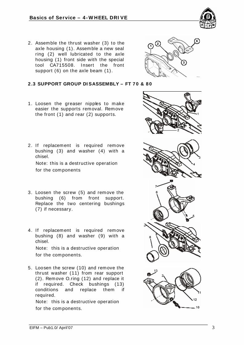
2. Assemble the thrust washer (3) to the axle housing (1). Assemble a new seal ring (2) well lubricated to the axle housing (1) front side with the special tool CA715508. Insert the front support (6) on the axle beam (1).
2.3 SUPPORT GROUP DISASSEMBLY – FT 70 & 80
1. Loosen the greaser nipples to make easier the supports removal. Remove the front (1) and rear (2) supports.
2. If replacement is required remove bushing (3) and washer (4) with a chisel.
Note: this is a destructive operation for the components
3. Loosen the screw (5) and remove the bushing (6) from front support. Replace the two centering bushings (7) if necessary.
4. If replacement is required remove bushing (8) and washer (9) with a chisel.
Note: this is a destructive operation for the components.
5. Loosen the screw (10) and remove the
thrust washer (11) from rear support (2). Remove O.ring (12) and replace it if required. Check bushings (13) conditions and replace them if required.
Note: this is a destructive operation for the components.

Basics of Service – 4-WHEEL DRIVE
EIFM – Pub1.0/ April’07 4
2.4 SUPPORT GROUP ASSEMBLY – FT 70 & 80
1. Assemble washers (4) and (9) and bushings (8) and (3) on axle housing.
2. Place front support (1) on a workbench and assemble bushing (6). Tighten locking bolt (5) to the prescribed torque.
3. Grease and install a new O-Ring (12) in the thrust bushing (11). Insert the thrust bushing into rear support (2).
4. Assemble the front (1) and rear (2) supports on central body. Warning: do not damage the O-Ring.
2.5 STEERING CYLINDER GROUP – FT 60

Basics of Service – 4-WHEEL DRIVE
EIFM – Pub1.0/ April’07 5
2.5.1 DISASSEMBLY– FT 60
1. Loosen the nut (1) with enough turns till it is protruding over the threaded pin end of the tie rod (3).Beat on the nut (1) with an appropriate hammer in order to disjoin the tie rod (3) from the swivel housing (2).Warning: don’t beat on the threaded pin end of the tie rod (3).
Note: this is a destructive operation for the nut (1).Repeat the whole sequence at the other side.
2. Remove the tie rods (3) and (12) by loosing the nuts (4) and (12) with a suitable wrench, then check them conditions. Unscrew the fastening screws (6) and take the steering cylinder (7) out of its housing, if necessary use a rubber hammer. Remove only parts that need to be overhauled and/or replaced.
3. Detach the cylinder head (15) from the cylinder case (19) and remove it from the rod (17).
Remove the rod (17) from the cylinder case (19). Remove all the seals and O-Rings (13, 14, 16, 18, 20 and 21) from the cylinder case (19), the cylinder head (15), and the rod (17).
2.5.2 ASSEMBLY– FT 60
1. Assemble new seals and O-Rings (13, 14, 16, 18, 20 and 21) on the cylinder head (15), on the rod piston (17) and on the cylinder body (19).
2. Fit the cylinder head (15) on the rod (17). Slide the pre-assembled rod (17) into the cylinder body (19).

Basics of Service – 4-WHEEL DRIVE
EIFM – Pub1.0/ April’07 6
3. Fit the tie rods (3) and (12), the ball joints (5) and (10), the nuts (4) and (11) to the ends of the rod (17), then tighten with a dynamometric wrench to the requested torque.
4. Install the steering cylinder (7) already assembled on the central body. Assemble and tighten the screws (6) with dynamometric wrench to the requested torque.
5. Align the swivel housing (8) with the axle. Screw the tie rod (12) so that its ball joint can be inserted into the swivel housing (8) arm. Note: it is important to unscrew the lock nut (11) to carry out this operation. Repeat the whole sequence of the mentioned operations to the other side.
6. Insert the ball joint of the tie rod (3) into its housing on the swivel housing (2). Assemble and tighten the lock nut (1) with a dynamometric wrench to the requested torque.
Repeat the whole sequence of the mentioned operations to the other side.
7. Screw the lock nuts (4) and (11) of the tie rods (3) and (12) only when the toe-in adjustment has been carried out.

Basics of Service – 4-WHEEL DRIVE
EIFM – Pub1.0/ April’07 7
2.6 STEERING CYLINDER GROUP DISASSEMBLY – FT 70 & 80
1. Unscrew and remove the nut (1).Slide the pin (2) and retrieve the washer (3).
2. Push with a punch the retaining Spiral pin (4) inside the rod pin (5). Slide the rod pin (5) from the steering cylinder and from the support and retrieve the relative spacers (6 and 7).
Remove the steering cylinder. Unscrew and remove the screws and washers of the cylinder support bracket. Remove the cylinder support bracket.
Warning: inspect the seals conditions and replace if necessary. Unscrew the cylinder head (8) from the steering cylinder body (9). Slide the rod (10) and piston (11) from the steering cylinder body (9). Unscrew the self locking nut (12) and remove the cylinder. Remove the rod (10) from the cylinder head.
3. Unloose the guide rod locknut of some turns till it is over the end of the threaded pin. Beat on the nut with a hammer in order to disjoin the guide rod from the swivel housing. Warning: don’t beat on the end of the threaded pin. Note: this is a destructive operation for the nut. Repeat the same operation on the second end of the guide rod. Remove and check the conditions of the guide rod.
Basics of Service – 4-WHEEL DRIVE
EIFM – Pub1.0/ April’07 8
2.6.1 STEERING CYLINDER GROUP ASSEMBLY – FT 70 & 80
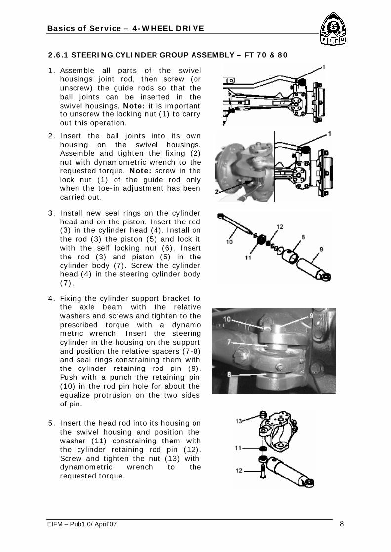
1. Assemble all parts of the swivel housings joint rod, then screw (or unscrew) the guide rods so that the ball joints can be inserted in the swivel housings. Note: it is important to unscrew the locking nut (1) to carry out this operation.
2. Insert the ball joints into its own housing on the swivel housings. Assemble and tighten the fixing (2) nut with dynamometric wrench to the requested torque. Note: screw in the lock nut (1) of the guide rod only when the toe-in adjustment has been carried out.
3. Install new seal rings on the cylinder head and on the piston. Insert the rod (3) in the cylinder head (4). Install on the rod (3) the piston (5) and lock it with the self locking nut (6). Insert the rod (3) and piston (5) in the cylinder body (7). Screw the cylinder head (4) in the steering cylinder body (7).
4. Fixing the cylinder support bracket to the axle beam with the relative washers and screws and tighten to the prescribed torque with a dynamo metric wrench. Insert the steering cylinder in the housing on the support and position the relative spacers (7-8) and seal rings constraining them with the cylinder retaining rod pin (9). Push with a punch the retaining pin (10) in the rod pin hole for about the equalize protrusion on the two sides of pin.
5. Insert the head rod into its housing on the swivel housing and position the washer (11) constraining them with the cylinder retaining rod pin (12). Screw and tighten the nut (13) with dynamometric wrench to the requested torque.

Basics of Service – 4-WHEEL DRIVE
EIFM – Pub1.0/ April’07 9
2.7 EPICYCLIC REDUCTION GEAR GROUP –FT 60, 70 & 80.
2.7.1 DISASSEMBLY
1. Drain the oil completely from the planetary carrier.
2. Unscrew and remove both fastening screws (3) of the planetary carrier (4) with a wrench.
3. Remove the planetary carrier (4) from the wheel hub and collect the relative O-Ring (5).
Basics of Service – 4-WHEEL DRIVE
EIFM – Pub1.0/ April’07 10
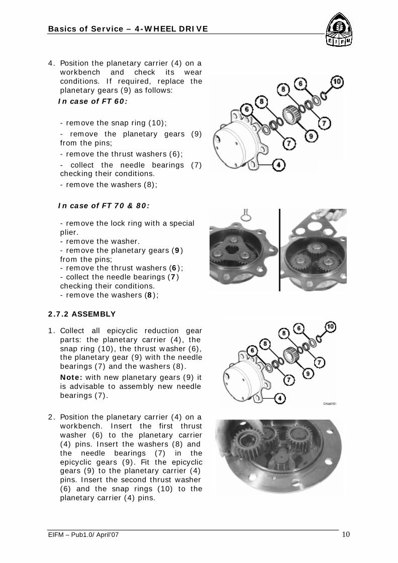
4. Position the planetary carrier (4) on a
workbench and check its wear conditions. If required, replace the planetary gears (9) as follows:
In case of FT 60:
- remove the snap ring (10); - remove the planetary gears (9) from the pins; - remove the thrust washers (6); - collect the needle bearings (7) checking their conditions. - remove the washers (8);
In case of FT 70 & 80:
- remove the lock ring with a special plier. - remove the washer. - remove the planetary gears (9) from the pins; - remove the thrust washers (6); - collect the needle bearings (7) checking their conditions. - remove the washers (8);
2.7.2 ASSEMBLY
1. Collect all epicyclic reduction gear parts: the planetary carrier (4), the snap ring (10), the thrust washer (6), the planetary gear (9) with the needle bearings (7) and the washers (8). Note: with new planetary gears (9) it is advisable to assembly new needle bearings (7).
2. Position the planetary carrier (4) on a workbench. Insert the first thrust washer (6) to the planetary carrier (4) pins. Insert the washers (8) and the needle bearings (7) in the epicyclic gears (9). Fit the epicyclic gears (9) to the planetary carrier (4) pins. Insert the second thrust washer (6) and the snap rings (10) to the planetary carrier (4) pins.

Basics of Service – 4-WHEEL DRIVE
EIFM – Pub1.0/ April’07 11
3. Assemble a new O-Ring (5) on the planetary carrier (4). Fit the epicyclic reduction gear assembly to the wheel hub. Assemble the screws (3) and tighten them to the prescribed torque.
4. Top up the oil on the wheel hub. Fit the filling/drain and level oil plug (1) on the planetary carrier (4) and tighten to the prescribed torque.
2.8 WHEEL HUB GROUP – FT 60, 70 & 80.
2.8.1 DISASSEMBLY
1. Insert a lever between the swivel housing (13) and the axle beam and fit it into the double U-Joint. With the lever push the double U-Joint in the direction of the wheel hub to allow the lock ring (1) removal. Warning: do not damage the double U-Joint.

Basics of Service – 4-WHEEL DRIVE
EIFM – Pub1.0/ April’07 12
2. Remove the lock ring (1) from the double U-Joint shaft. Collect the double U-Joint shaft washers (2, 3).
3. Unscrew and remove the screws (5) from the wheel carrier group (7).
4. In order to remove the wheel carrier group from its housing, screw two of the just removed screws (5) in the threaded extraction holes. Extract and remove the wheel carrier (7) together with the epicyclic ring gear (4).
5. Remove the steel lock ring (8) and disjoin the wheel carrier (7) from the epicyclic ring gear (4). Only if necessary, remove the centering bushes (6) from the wheel carrier with a hammer and the special tool CA715086.
6. Remove the wheel hub, using levers and a hammer to facilitate the operation. Note: collect the bearing cones (9, 11).
7. Position the wheel hub (10) on a flat surface and remove the bearing cups (9, 11) using a suitable extractor.

Basics of Service – 4-WHEEL DRIVE
EIFM – Pub1.0/ April’07 13
8. Remove the fastening screws (17, 16) from the upper (15) and lower (14) king pin. Danger: before removing the king pins, secure the swivel housing with a belt or a rope to a hoist or any other supporting device. Remove the king pins. Note: collect the belleville washers (18, 19).
9. Remove the swivel housing (13) from the axle beam and from the double U-Joint.
10.From the swivel housing (13) take the seal ring (12) out with a lever. Note: this is a destructive operation for the seal ring.
11.Position the swivel housing (13) on a flat surface and take the seal ring (20) out with a lever. Note: this is a destructive operation for the seal ring. Turn the swivel housing and take the bush (21) out, using a suitable drift and a hammer.
2.8.2 ASSEMBLY
1. If it has been previously removed, reassemble the steering mechanical retainer composed by the bolt (23) and the nut (22). Note: do not tighten the nut (22) until the steering angle adjustment has been done.

Basics of Service – 4-WHEEL DRIVE
EIFM – Pub1.0/ April’07 14
2. Force the bush (21) into the swivel housing (13) with the special tool CA715104 and a hammer or a press. Assemble the seal ring (20) on the swivel housing with the special tool CA715402 and a hammer. Fill of the gasket cavity with grease.
3. Assemble the seal ring (12) on the swivel housing (13) with the special tool CA715367 and a hammer.
4. If the cone (24) of the spherical joint has been previously removed, reassemble it to the lower king pin (14) using the special tool CA715451 under a press. Grease well the king pin housings with grease. Position the Belleville washers (18, 19) on the upper and on the lower king pin housings.
5. Danger: secure the swivel housing (13) with a belt or a rope to a hoist or any other supporting device. Protect the splined end of the axle shaft by winding it with an adhesive tape to avoid damage to the seal ring (20). Assemble the swivel housing (13) on the axle beam and after assembly, remove completely the adhesive tape.
6. Assemble the king pins, the lower (14) and the upper (15), and tighten the retaining screws (16) and (17) to the requested torque. Note: make sure that the belleville washers (18) and (19) remain in their position.
7. Position the wheel hub (10) on a workbench and force both bearing cups (9, 11) in position with the special tool CA715085 under a press or with a hammer.

Basics of Service – 4-WHEEL DRIVE
EIFM – Pub1.0/ April’07 15
8. Assemble the bearing cone (11) on the swivel housing end. Assemble the wheel hub (10) on the swivel housing and fit the other bearing cone (9).
9. Position the wheel carrier (7) on a workbench and force the bushes (6) to the carrier surface level with the special tool CA715086. At least two bushes (diametrically-opposed) should be set slightly higher than the carrier surface level to be used as dowel pins.
10.Assemble the wheel carrier (7) and epicyclic ring gear (4) group with the special locking ring (8).
11.Assemble the wheel carrier group on the wheel hub using the two projecting bushes as dowel pins and screw the relative screws (5) in order to put in contact the ring bevel gear with the wheel hub.
12.Force all the hub dowel bushes (6) completely with the special tool CA715086 and a hammer. Apply sealant on fastening screws (5) thread. Assemble the wheel carrier (7) fastening screws (5) and tighten to the requested torque.
A= 11.975 - 12.025 B= 52.230 - 52.280
C= 20.000 - 20.100
The special operation “Set Right” of the bearings does not require preload or backlash adjustment. Anyway, before assembling new components check the indicated dimensions.

Basics of Service – 4-WHEEL DRIVE
EIFM – Pub1.0/ April’07 16
13.Insert a lever between the swivel
housing (13) and the axle beam and fit it into the double U-Joint. With the lever push the double U-Joint in the direction of the wheel hub to make easier the lock ring (1) insertion. Warning: do not damage the double U-Joint.
14.Slide the thrust washers (2, 3) into the double U-Joint shaft and lock it with the snap ring (1), inserting it at the end of the splined hub and pushing it into its housing. Push the double U-Joint thoroughly and check the lock ring (1) is correctly fitted in its seat.
2.9 AXLE BEAM GROUP – FT 60, 70 & 80.
2.9.1 DISASSEMBLY
1. Remove the double U-Joint (7) from the axle beam (1).

Basics of Service – 4-WHEEL DRIVE
EIFM – Pub1.0/ April’07 17
2. Remove the seal ring (6) from the axle beam (1) with a lever. Note: this is a destructive operation for the seal ring. Remove the bush (5) from the axle beam (1) only if the wear conditions require this. Warning: be careful not to damage the bush housing. Collect the spacer (2) from the upper king pin housing. Remove the upper king pin bush (3) and the ball bearing cup (4) from the king pin housings using a suitable extractor only if the wear conditions require this.
2.9.2 ASSEMBLY
1. Assemble the upper king pin bush (3) on the axle beam housing with the special tool CA119220 and a hammer. Assemble the ball bearing cup (4) on the axle beam housing with the special tool CA715451 and a hammer. Note: to make the assembly easier, it is advisable to cool the upper king pin bush (3) and the ball bearing cup (4) at a temperature lower than -100 °C. Warning: wear safety gloves. Assemble the spacer (2) to the upper king pin housing.
2. Assemble the bush (5) on the axle beam (1) with the special tool CA715452 and a hammer. Assemble the seal rings (6) on the axle beam (1) with the special tool CA715453 and a hammer. Note: grease carefully the seal ring.
3. Insert the double U-Joint (7) inside the axle beam (1). Warning: be careful not to damage the seal ring (6).
Basics of Service – 4-WHEEL DRIVE
EIFM – Pub1.0/ April’07 18
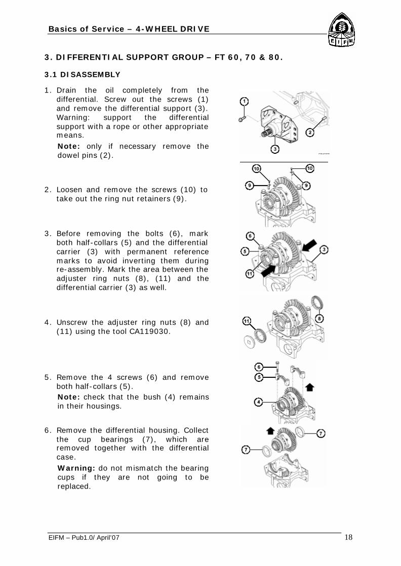
3. DIFFERENTIAL SUPPORT GROUP – FT 60, 70 & 80.
3.1 DISASSEMBLY
1. Drain the oil completely from the differential. Screw out the screws (1) and remove the differential support (3). Warning: support the differential support with a rope or other appropriate means. Note: only if necessary remove the dowel pins (2).
2. Loosen and remove the screws (10) to take out the ring nut retainers (9).
3. Before removing the bolts (6), mark
both half-collars (5) and the differential carrier (3) with permanent reference marks to avoid inverting them during re-assembly. Mark the area between the adjuster ring nuts (8), (11) and the differential carrier (3) as well.
4. Unscrew the adjuster ring nuts (8) and (11) using the tool CA119030.
5. Remove the 4 screws (6) and remove both half-collars (5). Note: check that the bush (4) remains in their housings.
6. Remove the differential housing. Collect
the cup bearings (7), which are removed together with the differential case. Warning: do not mismatch the bearing cups if they are not going to be replaced.

Basics of Service – 4-WHEEL DRIVE
EIFM – Pub1.0/ April’07 19
3.2 ASSEMBLY
1. Assemble the bearings cups (7) on the differential housings. Warning: Do not mismatch the bearings cup if they are not going to be replaced.
2. Check that all bushes (4) are in their
housings. Position the complete differential box on the differential carrier (3). Warning: check the right side of the bevel crown assembly. Move the differential group so to place the bevel crown gear on the pinion. Position both half collars (5) on their seats using their previously traced reference marks with the reference marks on the differential carrier. Lock both half collars with their fastening bolts (6).
3. Assemble and tighten both adjuster ring nuts (8) and (11) in the differential support (3) with special tool CA119030, till the backlash is eliminated and the differential bearings are slightly preloaded. Note: check that the differential bearings are well settled; if necessary; knock slightly with a soft hammer, in order to properly set the bearings in position.
4. Position a magnetic-base dial gauge on the differential support (3), so that the feeler stylus touches the surface of one tooth of the crown gear with a 90° angle. Lock the pinion and move the crown gear alternatively and note the pinion-ring gear backlash, measured with the comparator. Repeat the operation on two or more points (teeth), rotating the crown gear, so that to obtain an average value. Check if the measured backlash value is within the requested range: 0.17-0.23 mm –FT 60; 0.16-0.22 mm – FT 70&80 Carry out the adjustment by operating on the adjuster ring nuts (8) and (11) with the appropriate tool CA119030.

Basics of Service – 4-WHEEL DRIVE
EIFM – Pub1.0/ April’07 20
5. Adjust the adjuster ring nuts (8) and (11), remembering that: - if the measured backlash is less than the given tolerance range, unscrew the adjuster ring nut (8) and screw in the adjuster ring nut (11) by the same measure (A); - if the measured backlash is greater than the given tolerance range, unscrew the adjuster ring nut (11) and screw in the adjuster ring nut (8) by the same measure (B).
6. Once the adjustment of the pinion-ring gear backlash has been carried out, check also that there is a minimum preloading on the differential box bearings. Repeat the whole sequence of the above mentioned operations till the indicated conditions are reached.
7. Once the pinion-ring gear backlash has been established, measure the total preloading T of the bearings (pinion-crown bevel gear system), using a dynamometer whose cord is wound on the pinion splined end. The measured value should be within the following range: T=(P+5.8)-(P+8.7) Kgm – FT 60 T=(P+3.9)-(P+5.9) Kgm – FT 70 & 80 Where P is the effectively measured pinion preloading. Warning: all preloadings must be measured without seal ring.
8. If the measurement is not within the requested range, check well the assembly of each component and operate on the adjuster ring nuts (8) and (11) of the differential support (3): - if the total preloading is less than the given range, screw in both adjuster ring nuts (8) and (11) by the same measure, keeping the pinion-ring gear backlash value unchanged (A); - if the total preloading is greater than the given range, unscrew both adjuster ring nuts (8) and (11) by the same measure, keeping the pinion-ring gear backlash value unchanged (B).

Basics of Service – 4-WHEEL DRIVE
EIFM – Pub1.0/ April’07 21
9. Once all the adjustment operations have been completed, fit the adjuster ring nut retainers (9) and their respective screws (10), tightening them to the requested torque with a dynamometric wrench. Warning: turn the adjuster ring nuts (8) and (11) slightly in order to allow the assembly.
10.Tighten the bolts (6) of both half collars (5) to the requested torque (Sec. C.6) with a dynamometric wrench.
11.Before matching surfaces, make sure that they are perfectly clean, degrease and clean them with appropriate detergents. Spread a film of adhesive on the contact surface between the axle beam (1) and the differential carrier (3). Note: check that the dowel pins (2) are in their housing. Position the differential carrier on the axle housing, and tighten the retaining screws (1) to the requested torque.
12.To test the marks of the bevel gear teeth, paint the ring gear with red lead paint. The marking test should be always carried out on the ring bevel gear teeth and on both sides.
OK -> Correct contact: If the bevel gear is well adjusted, the mark on the teeth surfaces will be regular. Z -> Excessive contact on the tooth tip: Approach the pinion to the ring bevel gear and then move the ring bevel gear away from the pinion in order to adjust the backlash. X -> Excessive contact at the tooth base: Move the pinion away from the ring bevel gear and then approach the ring bevel gear to the pinion in order to adjust the backlash.

Basics of Service – 4-WHEEL DRIVE
EIFM – Pub1.0/ April’07 22
Movements to correct: 1 -> move the pinion for type X contact
adjustment. 2 -> move the pinion for type Z contact
adjustment.
4. DIFFERENTIAL GROUP – FT 60, 70 & 80.
4.1 DISASSEMBLY
1. Lock the differential in a clamp. Unscrew the fastening bolts (1) and remove the bevel gear crown (11). Warning: this will make both differential half housing (3 and 10) free, so take care not to drop the internal components.
2. Disassemble the two differential half housing (3 and 10). Note: before disjoin the half housing make marks to be used as reference during assembly. Disassemble all the components. Check the operating and wear conditions of the components.
3. Remove the bearing cones (2) from the half boxes (3 and 10) using a standard extractor.

Basics of Service – 4-WHEEL DRIVE
EIFM – Pub1.0/ April’07 23
4.2 ASSEMBLY
1. Assemble the bearing cones (2) on the half housing (3 and 10), using the special tool CA715083 and a hammer.
2. Position a half housing (3) on a
workbench and assemble all inner components (locking differential counter discs (4), sun gears (5), spider (9), spider gears (7), thrust washers (6), pin (8)), as shown in figure. Join the two half boxes, aligning the reference marks made upon them.
3. Place the bevel gear (11) on the differential housing. Apply sealant on the threads and tighten the bolts (1) to the requested torque.
5. PINION GROUP – FT 60, 70 & 80.

Basics of Service – 4-WHEEL DRIVE
EIFM – Pub1.0/ April’07 24
5.1 DISASSEMBLY
1. Fit the differential carrier in a vise. Unscrew the lock nut (10) using special tools CA715080 and CA715081. Note: this operation will irretrievably damage the lock nut (10).
2. Remove the ring nut (10) and collect its retaining washer (9).
3. Tap the shaft with a soft hammer to remove the bevel pinion (1). Warning: take care not to drop the bevel pinion (1). Collect the washers (4) and (6), the collapsible spacer (5) and the bearing cone (8).
4. Place the differential carrier (7) on a flat surface and remove the bearing cups (3) and (8) using a drift and a hammer.
5. To remove the bearing cone (3) of the bevel pinion (1), use a standard extractor. Collect the bearing cone (3) and the underlying shim (2).
6. Check all pinion components for wear. Warning: the ring nut (10) and the collapsible spacer (5) must be replaced when reassembling the unit.
Basics of Service – 4-WHEEL DRIVE
EIFM – Pub1.0/ April’07 25
5.2 Assembly
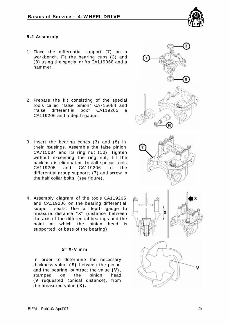
1. Place the differential support (7) on a workbench. Fit the bearing cups (3) and (8) using the special drifts CA119068 and a hammer.
2. Prepare the kit consisting of the special tools called “false pinion” CA715084 and “false differential box” CA119205 e CA119206 and a depth gauge.
3. Insert the bearing cones (3) and (8) in their housings. Assemble the false pinion CA715084 and its ring nut (10). Tighten without exceeding the ring nut, till the backlash is eliminated. Install special tools CA119205 and CA119206 to the differential group supports (7) and screw in the half collar bolts. (see figure).
4. Assembly diagram of the tools CA119205 and CA119206 on the bearing differential support seats. Use a depth gauge to measure distance “X” (distance between the axis of the differential bearings and the point at which the pinion head is supported, or base of the bearing).
S=X-V mm
In order to determine the necessary thickness value (S) between the pinion and the bearing, subtract the value (V), stamped on the pinion head (V=requested conical distance), from the measured value (X).

Basics of Service – 4-WHEEL DRIVE
EIFM – Pub1.0/ April’07 26
Select the shim (2) of thickness value (S) from the range of available shims, and fit to shaft under the pinion head.
SHIMS RANGE mm
2.5 2.6 2.7 2.8 2.9 Thick ness 3.0 3.1 3.2 3.3 3.4
5. Once you have chosen and inserted the suitable shim (2) with the chamfer against the gear, force the bearing (3) into the pinion shaft (1) with the special tool CA715082 under a press, making sure that it is well set. Insert the shims (4) and (6) and a new collapsible spacer (5). Note: use always a new collapsible spacer (5).
6. Insert the bevel pinion (1) unit into the differential support housing (7) and the bearing cone (8) into the pinion shaft, as shown in figure. In order to force the bearing (8) into position, use the special tool CA715082 and a hammer. It is advisable to offer resistance, for example a sledge, to the beating force.
7. Insert the ring nut washer (9) and screw a new lock ring nut (10) on the pinion end.
8. Screw the ring nut (10) in, using the wrench for ring nut CA715080 and for pinion retainer CA715081. Warning: the torque setting is given by the preloading measurement on bearings (3) and (8); tighten the ring nut (10) gradually. Note: if the tightening is excessive, the elastic spacer (5) must be replaced and the procedure repeated. When you check the preloading, it is advisable to beat slightly both pinion ends (1) with a soft hammer, so as to help setting the bearings (3) and (8).

Basics of Service – 4-WHEEL DRIVE
EIFM – Pub1.0/ April’07 27
P=10.6-16 Kg.m
Carry out the preloading measurement P of the pinion taper roller bearings (3) and (8), using a dynamometer whose cord is wound on the end of pinion spline (1). The adjustment is carried out by increasing the ring nut (10) torque gradually, being careful not to exceed. Warning: all preloadings must be measured without the seal ring.
9. Once the requested preloading value is achieved, stake the ring nut (10), using a hammer and a chisel.
6. TOE-IN/STEERING ANGLE – FT 60.
6.1 TOE-IN ADJUSTMENT – FT 60.
1. Put two equal one-meter-long linear bars on the wheel sides and lock them with two nuts on the wheel hub stud bolt. Warning: the two bars should be fixed on their middle so that they are perpendicular to the supporting surface and parallel to the pinion shaft axis; align the two bars.

Basics of Service – 4-WHEEL DRIVE
EIFM – Pub1.0/ April’07 28
2. Measure the distance in mm M between the bars ends with a tapeline. Note: keep the minimum value, swinging the measurement point.
3. Check that the difference of the
measurements between the wheel hubs diameters ends is within the requested tolerance range. The nominal toe-in value A is referred to the external diameter of the wheel hubs flange, therefore the measured value M at the bars ends must be related to the ratio between length of the bar and flange diameter:
Nominal toe-in (sec. C.4) = A0-2 measured toe-in= M 0-5
4. If toe-in is incorrect, operate with two wrenches on the guide rods (1) and (2) screwing in and out the two joint tie rods (5) and (6) equally till the toe-in is within the requested tolerance.
5. After adjusting, screw in the lock nuts (3) and (4) of the guide rods (1) and (2) to the requested tightening torque.
Basics of Service – 4-WHEEL DRIVE
EIFM – Pub1.0/ April’07 29
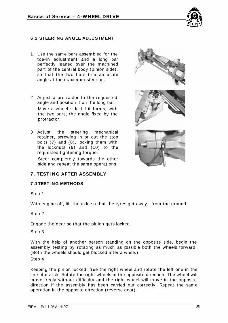
6.2 STEERING ANGLE ADJUSTMENT
1. Use the same bars assembled for the toe-in adjustment and a long bar perfectly leaned over the machined part of the central body (pinion side), so that the two bars form an acute angle at the maximum steering.
2. Adjust a protractor to the requested angle and position it on the long bar. Move a wheel side till it forms, with the two bars, the angle fixed by the protractor.
3. Adjust the steering mechanical retainer, screwing in or out the stop bolts (7) and (8), locking them with the locknuts (9) and (10) to the requested tightening torque. Steer completely towards the other side and repeat the same operations.
7. TESTING AFTER ASSEMBLY
7.1TESTING METHODS
Step 1 With engine off, lift the axle so that the tyres get away from the ground.
Step 2 Engage the gear so that the pinion gets locked.
Step 3 With the help of another person standing on the opposite side, begin the assembly testing by rotating as much as possible both the wheels forward. (Both the wheels should get blocked after a while.)
Step 4 Keeping the pinion locked, free the right wheel and rotate the left one in the line of march. Rotate the right wheels in the opposite direction. The wheel will move freely without difficulty and the right wheel will move in the opposite direction if the assembly has been carried out correctly. Repeat the same operation in the opposite direction (reverse gear).

Basics of Service – 4-WHEEL DRIVE
EIFM – Pub1.0/ April’07 30
IF ONE WHEEL DOES NOT ROTATE FREELY IN BOTH DIRECTIONS, then check step by step all assembly operations. Check and see that the brakes are regulated correctly and functioning properly.
POSSIBLE CAUSES PROBLEMS
1 2 3 4 5 6 7 8 9 10 11
- Wheel vibration; front tyre resistance; half shaft breakage.
- Steering is difficult; vehicle goes straight while its turning
- No differential action; jamming while steering.
- No differential action; jamming while steering.
- Uneven wear of tyre.
- Friction noise.
- Vibration during forward drive, intermittent noise.
1. Incorrect installation / defective axle: Correct installation or repair or replace the differential in case it does not survive any one of the test phases.
2. Overloading / incorrect weight distribution: Remove excessive weight and redistribute load, following instructions related to the vehicle. 3. Different rotation radius of the tyres: If one tyre has a smaller radius, it will cause partial wheel slipping when force is applied. The other tyre with bigger radius will have to support all the work. Replace the tyre or adjust pressure to have same radius on both tyre. 4. Broken half shaft: It is not advisable to operate the vehicle with a broken half shaft. It is acceptable to move the vehicle (engine off unloaded) a few meters away only.

Basics of Service – 4-WHEEL DRIVE
EIFM – Pub1.0/ April’07 31
5. Bent half shaft: Replace half shaft. 6. Blocked differential: Abnormal functioning of the differential or breakage/ blockage of command device. Verify assembly and all components. Vehicles with wide steering angle may proceed with kicks, have steering difficulty or cause pneumatic wearing at sharp turns. Reduce the steering angle to minimum and decelerate when the vehicle begins to kick. 7. Incorrect wheel adjustment: Verify group integrity and wheel side bearings. Adjust according. 8. Spoiled or worn out axle parts: Check the condition of ring gear, pinion gear, bearings etc. Replace when ever necessary. 9. Contamination in the axle box or incorrect assembly of parts: Look for foreign particles. Check assembly of the various parts of the axle. 10. Incorrect adjustment of bevel gear set: Parts of the transmission
worn out. (Transmission gears, U joints, etc.) Replace or adjust as required.

Basics of Service – 4-WHEEL DRIVE
EIFM – Pub1.0/ April’07 32
8. SPECIFICATION
FT 60 FT 70 & 80
Bevel gear ratio 1.812 / 1 2.308 / 1
Epicyclic reduction gear ratio 5.00 / 1 6.0 / 1
Total ratio 9.06 / 1 13.85/ 1
Dry weight 182 Kg 225 Kg
Input rotation CLOCK WISE (C.W.) COUNTER CLOCK WISE (C.C.W.)
Steering angle 550- 2 Max 50°
Toe-in A0- 2 A0
- 3
Bevel gear set backlash 0.17-0.23 mm 0.16-0.22 mm
Pinion bearings preloading (measured on D=30.5 mm without seals)
P= 10.71-16 Kg.m
Total pinion-ring gear bearing preloading (measured on D=30.5 mm without seals)
T= (P+5.8)-(P+8.7) Kg.m T= (P+3.9)-(P+5.9) Kg.m
Differential oil capacity 4.0 liters 4.5 liters
Epicyclic reduction gear oil capacity each side
0.5 liters 0.6 liters
Oil specification: USE RECOMMENDED OIL ENRICHED IN ADDITIVES.
API GL5 SAE 80W90 EP
API GL5 SAE 80W90 EP
Grease specification
TECNOLUBE SEAL POLYMER 400/L
(DIN = KHER1R ISO-I-XMR-XM2)
AGIP MU/EP2 - use on king pin only
TECNOLUBE SEAL POLYMER 400/L
(DIN = KHER1R ISO-I-XMR-XM2)
AGIP MU/EP2 - use on
king pin only Differential support bush sealant (A0). See: Sealing compounds and adhesives
AUTEX or equivalent N.A

Basics of Service – 4-WHEEL DRIVE
EIFM – Pub1.0/ April’07 33
9. ADHESIVE/SEALANT APPLICATION POSITION:
Adhesive/Sealant Application Position
Apply on the contact surfaces
Apply on bolts thread / on pins
Gasket sealant
Carraro Ref. Presence Adhesive make
and type Technical
characteristics Strength
A1 Loctite® 510
Superbond® 529 Flat surface sealing High
A2 Loctite® 573
Superbond® 519 Flat surface sealing Low
A3 Loctite® 518
Superbond® 539 Uneven surface sealing High
Thread parts sealant
Carraro Ref. Presence Adhesive make
and type Technical
characteristics Strength
B1 Loctite® 542
Superbond® 321 Locking of
threaded parts Medium

Basics of Service – 4-WHEEL DRIVE
EIFM – Pub1.0/ April’07 34
Thread parts sealant
Carraro Ref. Presence Adhesive make
and type Technical
characteristics Strength
B2 Loctite® 270
Superbond® 331 Locking of
threaded parts High
B3 Loctite® 986/AVX Superbond® 438
Locking of threaded parts
High, special appl.
Fixing parts sealant
Carraro Ref. Presence Adhesive make
and type Technical
characteristics Strength
C1 Loctite® 405
Superbond® istant 25
Fixing adhesive Medium bond
C2 Loctite® 638
Superbond® 433 Fixing adhesive Strong bond
C3 Loctite® 542
Superbond® 321 Fixing adhesive Medium bond
C4 Loctite® 496
Superbond® SB14 Rubber fixing adhesive Strong bond
Fill in excess with MU/EP2 grease
Before assembling, to grease indicated surface with POLYMER 400 grease

Basics of Service – 4-WHEEL DRIVE
EIFM – Pub1.0/ April’07 35
10. OVERALL DIMENSIONS – FT 60:

Basics of Service – 4-WHEEL DRIVE
EIFM – Pub1.0/ April’07 36
10.1 OVERALL DIMENSIONS – FT 70 & 80:

Basics of Service – 4-WHEEL DRIVE
EIFM – Pub1.0/ April’07 37
11. OIL FILLING AND LEVEL PLUG – FT 60:
11.1 OIL FILLING AND LEVEL PLUG – FT 70 & 80:
DESCRIPTION POSITION
Oil filling and level plug 1
Oil breather 2
Filling, level and drain plug of epicyclic reduction gear oil 3
Oil drain plug 4
Greasing points 5

Basics of Service – 4-WHEEL DRIVE
EIFM – Pub1.0/ April’07 38
12. Oil change and checks
1. Danger: risk of violent oil ejection, follow carefully all the safety procedures indicated in this manual and in the vehicle manual. Before draining the oil from axle housing, use the breather (2) to release possible internal pressure.
2. To drain the oil remove the level plug (1) and the drain plug (4). Danger: risk of violent oil ejection. See: the first point. Drain all oil. Clean the plug (4) and tighten it to the prescribed torque.
3. Always use the breather (2) to release possible internal pressure. Unscrew the oil fill plug (1) and fill to the bottom of the level plug hole with the specified oil. Wait to allow the oil to flow through the axle. Check oil level and fill to the specified level if necessary. Screw the plug (1) to the prescribed torque.
4. Before draining the oil from wheel end rotate the wheel end so that the plug (3) is at the highest position [pos.A] and partially unscrew to release possible pressure. Rotate the wheel end so that the plug (3) is toward the ground [pos.B]. Remove the plug and drain the oil.
5. Rotate the wheel end so that the hole (3) is in the position shown in figure. Fill to the bottom of the fill plug hole with specified oil. Tighten the plug to the prescribed torque.

Basics of Service – 4-WHEEL DRIVE
EIFM – Pub1.0/ April’07 39
13. SERVICE SCHEDULE Specified lubrication intervals are for standard-duty use. Severe operating conditions require shorter lubrication intervals.
Operation First time Seasonally or every
1500 operating hours(1)
Axle oil change 150 - 200 hours
Lubrication works
Check and adjust oil level 50 - 100 hours Monthly
Clean magnetic oil plugs 150 - 200 hours Every oil change
Clean oil breather Monthly
Greasing 150 - 200 hours Weekly
This operation must be performed only by personnel authorized by the manufacturer.
This operation must be performed only by trained personnel. (1) Which of both condition comes first.
LUBRICANTS APPLICATION RANGE

Basics of Service – 4-WHEEL DRIVE
EIFM – Pub1.0/ April’07 40
14. TIGHTENING TORQUES –FT 60, 70 & 80:
15. TROUBLESHOOTING
Problem Cause Action
1. Ring gear tooth broken on the outer side
1. Excessive gear load compared to the one foreseen 2. Incorrect gear adjustment (excessive backlash) 3. Pinion nut loosened
Replace bevel gear set. Follow carefully the recommended operations for the adjustment of bevel gear set backlash.
2. Ring gear tooth broken on the inner side
1. Load bump 2. Incorrect gear adjustment (insufficient backlash) 3. Pinion nut loosened
Replace bevel gear set. Follow carefully the recommended operations for the adjustment of bevel gear set backlash
3. Pinion or ring gear teeth worn
1. Insufficient lubrication 2. Contaminated oil 3. Incorrect lubrication or depleted additives 4. Worn out pinion bearings that cause an incorrect pinion axle backlash and wrong contact between pinion and ring.
Replace bevel gear set. Follow carefully the recommended operations for the adjustment of bevel gear set backlash Use correct lubricants, fill up to the right levels and replace according to the recommended program.

Basics of Service – 4-WHEEL DRIVE
EIFM – Pub1.0/ April’07 41
Problem Cause Action
4. Overheated ring and pinion teeth. See if gear teeth have faded
1. Prolong ed functioning at high temperatures 2. Incorrect lubrication 3. Low oil level 4. Contaminated oil
Replace bevel gear set. Use proper lubrication, fill up to right level and replace at recommended program.
5. Pinion teeth pitting.
1. Excessive use 2. Insufficient lubrication
Replace bevel gear set. Use correct lubrication, fill up to the right level and substitute at recommended Intervals.
6. Axle beam body bent.
1. Vehicle over loaded 2. Vehicle's accident 3. Load bump
Replace axle beam body
7. Worn out or pitted bearings.
1. Insufficient lubrication 2. Contaminated oil 3. Excessive use 4. Normal wear out 5. Pinion nut loosened
Replace bearings. Use correct lubrication fill up, to the right level and replace at recommended Intervals.
8. Oil leakage form gaskets and seals.
1. Prolonged functioning at high temperature of the oil 2. Oil gasket assembled incorrectly 3. Seal lip damaged 4. Contaminated oil
Replace the gasket or seal and matching surface if damaged. Use correct lubrication and replace at recommended intervals.
9. Excessive wearing out of input flange spline.
1. Exhaustive use 2. Pinion nut loosened 3. Pinion axle backlash
Replace the flange. Check that the pinion spline is not excessively worn out. Replace bevel gear set if required.
10.Fatigue failure of pinion teeth See if the fracture line is well defined (wave lines, beach lines)
1. Exhaustive use 2. Continuous overload Replace bevel gear set
11.Pinion and ring teeth breakage
1. Crash load of differential components
Check and/or replace other differential components.

Basics of Service – 4-WHEEL DRIVE
EIFM – Pub1.0/ April’07 42
Problem Cause Action
12.Side gear spline worn out. Replace all scratched washers. (Excessive backlash)
1. Excessive use Replace differential gear group. Replace half shaft if required
13.Thrust washer surface worn out or scratched.
1. Insufficient lubrication 2. Incorrect lubrication 3. Contaminated oil
Use correct lubrication and fill up to right level. Replace at intervals recommended. Replace all scratched washers and those with 0,1mm thickness lower than the new ones.
14.Inner diameter of tapered roller bearing worn out.
1. Excessive use 2. Excessive pinion axial backlash 3. Insufficient lubrication 4. Contaminated oil
Replace bearing. Check pinion axial backlash. Use proper lubrication, fill up to right level and replace at recommended intervals.
15.Bent or broken half shaft.
Vehicle intensively operated or overloaded Replace
16.Half shaft broken at wheel side.
1. Wheel support loosened 2. Beam body bent
Replace Check that wheel support is not worn out or wrongly adjusted.
16. AXLE PROBLEMS AND DIAGNOSIS
Problem Cause Action
1. Excessive backlash between pinion and ring gear.
1. Adjust
2. Worn out pinion and gear ring. 2. Replace
3. Worn out pinion bearings.
3. Replace
4. Pinion bearings loosened.
4. Adjust
1. Noise while driving
5. Excessive axial pinion backlash. 5. Adjust

Basics of Service – 4-WHEEL DRIVE
EIFM – Pub1.0/ April’07 43
Problem Cause Action
6. Worn out differential bearings 6. Replace
7. Differential bearings loosened 7. Adjust
8. Ring gear out of roundness
8. Replace
9. Low lubricant level 9. Oil level
10. Poor or wrong lubricant 10. Replace
1. Noise while driving
11. Bent half shaft 11. Replace
1. Noise coming from axle are usually heard when vehicle moves in neutral gear but are not loud.
1. Replace or adjust (see above)
2. Incorrect backlash between pinion and ring (sound heard while decelerating disappears while increasing the speed)
2. Replace
2. Noise while driving in neutral
3. Pinion or input flange worn out. 3. Adjust
1. Ring gear damaged 1. Replace bevel gear set 3. Intermittent noise
2. Differential box bolts loosened 2. Tighten to torque
1. Ring gear teeth or pinion damaged 1. Replace bevel gear set
2. Worn out bearings 2. Replace
3.Pinion spline worn out 3. Replace
4. Constant noise
4. Bent half shaft 4. Replace 1. Worn out differential
gears 1. Replace
2. Worn out differential box or spider 2. Replace
3. Differential thrust washers worn out
3. Replace
5. Noise while steering.
4. Half shaft spline worn out
4. Replace
Related Documents


