4 Understanding the Basics of the Injection Mold 4.1 Design Rules There are many rules for designing molds. These rules and standard practices are based on logic, past experience, convenience, and economy. For designing, mold making, and molding, it is usually of advantage to follow the rules. But occasionally, it may work out better if a rule is ignored and an alternativeway is selected. In this text, the most common rules are noted, but the designer will learn only from experience which way to go. The designer must ever be open to new ideas and methods, to new molding and mold materials that may affect these rules. 4.2 The Basic Mold 4.2.1 Mold Cavity Space The mold cavity space is a shape inside the mold, ‘‘excavated’’ (by machining the mold material) in such a manner that when the molding material (in our case, the plastic) is forced into this space it will take on the shape of the cavity space and, therefore, the desired product (Fig. 4.1). The principle of a mold is almost as old as human civilization. Molds have been used to make tools, weapons, bells, statues, and household articles, by pouring liquid metals (iron, bronze) into sand forms. Such molds, which are still used today in foundries, can be used only once because the mold is destroyed to release the product after it has solidified. Today, we are looking for permanent molds that can be used over and 9

Welcome message from author
This document is posted to help you gain knowledge. Please leave a comment to let me know what you think about it! Share it to your friends and learn new things together.
Transcript
4 Understanding the Basics of theInjection Mold
4.1 Design Rules
There are many rules for designing molds. These rules and standard practices
are based on logic, past experience, convenience, and economy. For designing,
mold making, and molding, it is usually of advantage to follow the rules. But
occasionally, it may work out better if a rule is ignored and an alternative way is
selected. In this text, the most common rules are noted, but the designer will
learn only from experience which way to go. The designer must ever be open to
new ideas and methods, to new molding and mold materials that may affect
these rules.
4.2 The Basic Mold
4.2.1 Mold Cavity Space
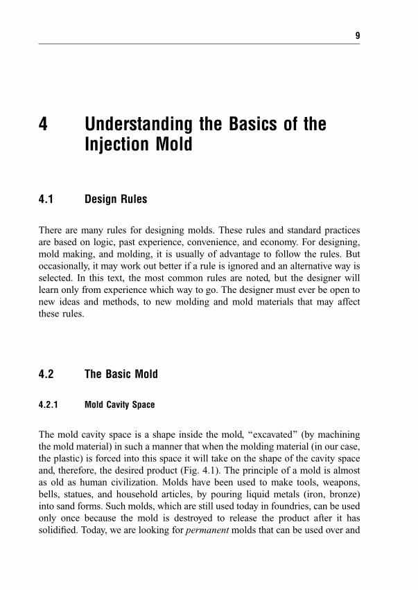
The mold cavity space is a shape inside the mold, `̀ excavated'' (by machining
the mold material) in such a manner that when the molding material (in our case,
the plastic) is forced into this space it will take on the shape of the cavity space
and, therefore, the desired product (Fig. 4.1). The principle of a mold is almost
as old as human civilization. Molds have been used to make tools, weapons,
bells, statues, and household articles, by pouring liquid metals (iron, bronze)
into sand forms. Such molds, which are still used today in foundries, can be used
only once because the mold is destroyed to release the product after it has
solidi®ed. Today, we are looking for permanent molds that can be used over and
9
over. Now molds are made from strong, durable materials, such as steel, or from
softer aluminum or metal alloys and even from certain plastics where a long
mold life is not required because the planned production is small. In injection
molding the (hot) plastic is injected into the cavity space with high pressure, so
the mold must be strong enough to resist the injection pressure without
deforming.
4.2.2 Number of Cavities
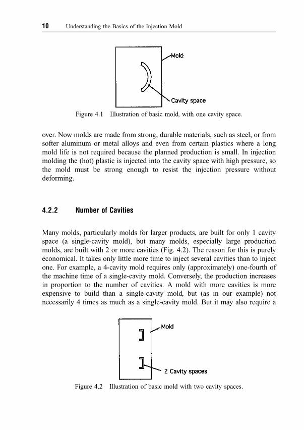
Many molds, particularly molds for larger products, are built for only 1 cavity
space (a single-cavity mold), but many molds, especially large production
molds, are built with 2 or more cavities (Fig. 4.2). The reason for this is purely
economical. It takes only little more time to inject several cavities than to inject
one. For example, a 4-cavity mold requires only (approximately) one-fourth of
the machine time of a single-cavity mold. Conversely, the production increases
in proportion to the number of cavities. A mold with more cavities is more
expensive to build than a single-cavity mold, but (as in our example) not
necessarily 4 times as much as a single-cavity mold. But it may also require a
Figure 4.1 Illustration of basic mold, with one cavity space.
Figure 4.2 Illustration of basic mold with two cavity spaces.
10 Understanding the Basics of the Injection Mold

larger machine with larger platen area and more clamping capacity, and because
it will use (in this example) 4 times the amount of plastic, it may need a larger
injection unit, so the machine hour cost will be higher than for a machine large
enough for the smaller mold. Today, most multicavity molds are built with a
preferred number of cavities: 2, 4, 6, 8, 12, 16, 24, 32, 48, 64, 96, 128. These
numbers are selected because the cavities can be easily arranged in a rectangular
pattern, which is easier for designing and dimensioning, for manufacturing, and
for symmetry around the center of the machine, which is highly desirable to
ensure equal clamping force for each cavity. A smaller number of cavities can
also be laid out in a circular pattern, even with odd numbers of cavities, such as
3, 5, 7, 9. It is also possible to make cavity layouts for any number of cavities,
provided such rules as symmetry of the projected areas around the machine
centerline (as explained later) are observed.
4.2.3 Cavity Shape and Shrinkage
The shape of the cavity is essentially the `̀ negative'' of the shape of the desired
product, with dimensional allowances added to allow for shrinking of the
plastic. The fundamentals of shrinkage are discussed later.
The shape of the cavity is usually created with chip-removing machine tools,
or with electric discharge machining (EDM), with chemical etching, or by any
new method that may be available to remove metal or build it up, such as
galvanic processes. It may also be created by casting (and then machining)
certain metals (usually copper or zinc alloys) in plaster molds created from
models of the product to be made, or by casting (and then machining) some
suitable hard plastics (e.g., epoxy resins). The cavity shape can be either cut
directly into the mold plates or formed by putting inserts into the plates.
4.3 Cavity and Core
By convention, the hollow (concave) portion of the cavity space is called the
cavity. The matching, often raised (or convex) portion of the cavity space is
called the core. Most plastic products are cup-shaped. This does not mean that
they look like a cup, but they do have an inside and an outside. The outside of
the product is formed by the cavity, the inside by the core. The alternative to the
cup shape is the ¯at shape. In this case, there is no speci®c convex portion, and
4.3 Cavity and Core 11
sometimes, the core looks like a mirror image of the cavity. Typical examples for
this are plastic knives, game chips, or round disks such as records. While these
items are simple in appearance, they often present serious molding problems for
ejection of the product. Usually, the cavities are placed in the mold half that is
mounted on the injection side, while the cores are placed in the moving half of
the mold. The reason for this is that all injection molding machines provide an
ejection mechanism on the moving platen and the products tend to shrink onto
and cling to the core, from where they are then ejected. Most injection molding
machines do not provide ejection mechanisms on the injection (`̀ hot'') side.
We have seen how the cavity spaces are inside the mold; now we consider
the other basic elements of the mold.
4.4 The Parting Line
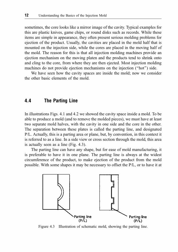
In illustrations Figs. 4.1 and 4.2 we showed the cavity space inside a mold. To be
able to produce a mold (and to remove the molded pieces), we must have at least
two separate mold halves, with the cavity in one side and the core in the other.
The separation between these plates is called the parting line, and designated
P/L. Actually, this is a parting area or plane, but, by convention, in this context it
is referred to as a line. In a side view or cross section through the mold, this area
is actually seen as a line (Fig. 4.3).
The parting line can have any shape, but for ease of mold manufacturing, it
is preferable to have it in one plane. The parting line is always at the widest
circumference of the product, to make ejection of the product from the mold
possible. With some shapes it may be necessary to offset the P/L, or to have it at
Figure 4.3 Illustration of schematic mold, showing the parting line.
12 Understanding the Basics of the Injection Mold

an angle, but in any event it is best to have is so that it can be easily machined,
and often ground, to ensure that it shuts off tightly when the mold is clamped
during injection. If the parting line is poorly ®nished the plastic will escape,
which shows up on the product as an unsightly sharp projection, or `̀ ¯ash,''
which must then be removed; otherwise, the product could be unusable. There is
even a danger that the plastic could squirt out of the mold and do personal
damage.
4.4.1 Split Molds and Side Cores
There are other parting (or split) lines than those that separate the cavity and
core halves. These are the separating lines between two or more cavity sections
if the cavity must separate (split or retract) to make it possible to eject the
molded product as the mold opens for ejection.
Figure 4.4 shows simple `̀ up and down'' molds. The machine clamping
force holds the mold closed at the P/L. (In (B) and (C), the parting line could be
anywhere on the outside of the rim, between the two positions shown, but is
preferred as in (B).) In (D) we must consider the injection pressure p (as shown
with small arrows inside the cavity space), which will force the two cavity
halves in the direction of the the large arrow m. This force also exists in the other
examples, but is resisted by the strength of the solid cavity walls, which do
slightly expand during injection and then return to their original shape once the
injection cycle is completed. Since these side forces can be considerable (see
Section 4.6), the mold plates (the `̀ mold shoe'') must be suf®ciently solid to
Figure 4.4 Schematic illustrations of location of parting lines (P/L) (only one half of
mold shown): (a) core, (b) cavity. (A) Simplest case: P/L at right angles to axis of mold.
(B and C) Product with rim but still simple. P/L can be either as in (B) or in (C). (D)
Simple product but with rim and projection. Cavity is split, creating an additional P/L 2.
4.4 The Parting Line 13
contain these forces and provide the necessary preload to prevent opening of the
mold during injection. These side cores, or split portions of the cavities, can
represent just small parts of the cavity, or even only small pins to create holes in
the side of the products, but they could also be sections molding whole sides of
a product, as, for example, with beverage crates or large pails.
4.5 Runners and Gates
In Fig. 4.3, we showed molds with cavity spaces and parting lines. Now, we
must add provisions for bringing the plastic into these cavity spaces. This must
be done with enough pressure so that the cavity spaces are ®lled completely
before the plastic `̀ freezes,'' that is, cools so much that the plastic cannot ¯ow
anymore. The ¯ow passages are the sprue, from where the machine nozzle (see
Fig. 3.1) contacts the mold, the runners, which distribute the plastic to the
individual cavities, and the gates, which are (usually) small openings leading
from the runner into the cavity space. We discuss the great variety of sprues,
runners, and gates later. We illustrate here only two methods of so-called cold
runners (see Fig. 4.5).
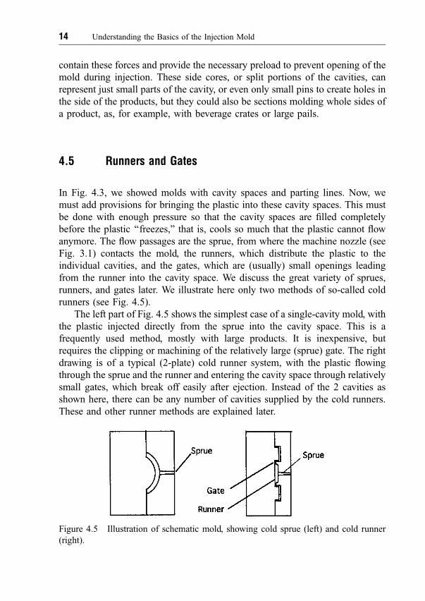
The left part of Fig. 4.5 shows the simplest case of a single-cavity mold, with
the plastic injected directly from the sprue into the cavity space. This is a
frequently used method, mostly with large products. It is inexpensive, but
requires the clipping or machining of the relatively large (sprue) gate. The right
drawing is of a typical (2-plate) cold runner system, with the plastic ¯owing
through the sprue and the runner and entering the cavity space through relatively
small gates, which break off easily after ejection. Instead of the 2 cavities as
shown here, there can be any number of cavities supplied by the cold runners.
These and other runner methods are explained later.
Figure 4.5 Illustration of schematic mold, showing cold sprue (left) and cold runner
(right).
14 Understanding the Basics of the Injection Mold

4.6 Projected Area and Injection Pressure
At this point we digress and consider injection pressure and how it affects mold
design (see Fig. 4.6). As the plastic ®lls the cavity space under high pressure p,
the pressure, in the direction of the mold (and machine) axisÐin other words, in
the direction of the motion of the clampÐwill tend to open the cavity at the
parting line. The separating force F created by the pressure p is equal to the
product of the pressure p times the projected area A, which is the area of the
largest projection of the product at the parting line. The arrow describing
projected area in Fig. 4.6 really describes an area not a line, as delineated in this
section view of the mold. The actual area can be seen (and measured) in a plan
view of the mold cavity. From this it becomes clear that the clamping force, the
force exerted on the mold by the molding machine, must be at least as great as
the force F to keep the mold from opening (cracking open) during injection.
The dif®culty is how to determine the value of the injection pressure p. We
can easily calculate the injection pressure inside the machine nozzle, which is
directly related to the size of the injection cylinder of the machine and the
hydraulic (oil) pressure supplying the injection cylinder. The injection pressure
at the machine nozzle, in general, is adjustable between any low values, to a high
of about 140 MPa (20,000 psi), in most molding machines, and in some
machines can be as high as 200 MPa (29,000 psi) or even higher. This pressure,
Figure 4.6 Portion of a schematic mold, showing a cavity ®lled with plastic under
pressure acting in all directions.
4.6 Projected Area and Injection Pressure 15

however, is greatly reduced (by the pressure drop) by the time the plastic passes
through the machine nozzle ori®ce, the runners, and the gates, and as it ¯ows
through the narrow passages of the cavity space. The ¯ow also depends largely
on the viscosity (de®ning the ease of ¯ow) of the plastic, which depends on its
chemistry and on its temperature (the higher the temperature, the lower the
viscosity). This area is the subject of much research and experimentation, and
computer programs are available to calculate the pressures and the ¯ow inside
the cavity space (see Appendix).
A good working assumption is a cavity pressure p of approximately
30±40 MPa (4000±5000 psi) for average product wall thicknesses of about
2±3 mm or more, and 40±50 MPa (5000±6000 psi) or even higher for thin-wall
products. For example, a disk of 100 mm (10 cm) diameter, with a thickness of
2 mm, will generate an opening force of (102 � p� 4) cm2 � 30 MPa � 235 kN
(approx. 26 US tons) per cavity.
4.6.1 Clamping Force
From the above example we see that a clamping force of at least 235 kN (26 US
tons) per cavity should be used to ensure that the mold will not crack open. If the
average wall of the product is thinner, or if the de®nition, that is, the accuracy
and clarity of reproduction of details in the cavity wall, is important, then the
pressure must be higher and a larger clamping force will be required.
4.6.2 Strength of the Mold
There are two other serious effects of the injection pressure p. First, as can be
seen in Fig. 4.6, the pressure also acts in the direction at right angles to the axis
of the mold. These forces, which are the product of the projection of the cavity
in this direction times the pressure p, will tend to stretch and de¯ect the cavity
walls outward. The greater the height H of the product, the greater will be this
force and the stronger must be the walls surrounding the cavity.
Second, the clamping force is applied as soon as the mold closes. At this
moment, the whole clamp force is resisted (`̀ taken up'') by the area of the land,
which is the area surrounding the cavity that touches the core side. If this area is
16 Understanding the Basics of the Injection Mold
too small, the land will be crushed and damage the sealing-off surfaces of the
parting line, eventually ruining the mold. Proper sizing of the land and correct
materials and hardness (steel, etc.), or other measures to counteract the clamping
forces are the solution to this problem. Also, the mold setup technician should
be informed by a nameplate attached to the mold that the recommended
maximum clamp force for the mold must not be exceeded during mold setup or
during operation.
4.6.3 Why Are High Injection Pressures Needed?
High injection pressures are needed to ensure that the mold is completely ®lled
during the injection cycle, with the desired clear surface de®nition. There are
several problems to consider.
(1) The thinner the wall thickness of the product, the more dif®cult it is to
push the plastic through the gap between cavity and core, thus requiring higher
pressures. Since material (the plastic) usually accounts for 50±80% of the total
cost of a molded product, it is highly desirable to reduce the weight (mass) of
plastic injected to a bare minimum. This usually means reducing the wall
thickness as far as possible without affecting the usefulness of the product. Over
the years, many products have been redesigned just to reduce the plastic mass of
a product. This is also why many modern injection molding machines provide
higher injection pressures than older ones.
(2) The colder the injected plastic, the higher its viscosity, and the more
dif®cult it becomes to ®ll the mold. The cost of the product depends directly on
the cycle time required to mold a product. The higher the melt temperature of
the plastic, the easier it will ¯ow and ®ll the mold. However, higher melt
temperatures also require increasing the cooling cycle time to bring the
temperature of the injected plastic down to a level where the product can be
safely ejected without distorting or otherwise damaging it. This means more
power (for heating and cooling), longer cycles, and therefore higher costs. It is
often better to inject at the lowest possible temperatures, even if more pressure is
needed to ®ll the mold. Note that higher injection pressures will require greater
clamping forces and a stronger, possibly larger, machine. Another solution to the
problem might be to select a plastic that ¯ows more easily. Such plastics,
however, are usually more expensive and may not be as strong as desired.
(3) High injection forces are needed for good surface de®nition. Typically,
this is important when molding articles such as compact discs, where the clarity
4.6 Projected Area and Injection Pressure 17
and precision of the surface de®nition is in direct relation to the quality of the
sound reproduction of the recording.
4.7 Venting
As the plastic ¯ows from the gate into the cavity space, the air trapped in it as
the mold closed must be permitted to escape. Typically, the trapped air is being
pushed ahead by the rapidly advancing plastic front, toward all points farthest
away from the gate. The faster the plastic entersÐwhich is usually desirableÐ
the more the trapped air is compressed if it is not permitted to escape, or vented.
This rapidly compressed air heats up to such an extent that the plastic in contact
with the air will overheat and possibly be burnt. Even if the air is not hot enough
to burn the plastic, it may prevent the ®lling of any small corners where air is
trapped and cause incomplete ®lling of the cavity. Most cavity spaces can be
vented successfully at the parting line, but often additional vents, especially in
deep recesses or in ribs, are necessary.
Another venting problem arises when plastic fronts ¯owing from two or
more directions collide and trap air between them. Unless vents are placed there
the plastic will not `̀ knit'' and may even leave a hole in the wall of the product.
This can be the case when more than one gate feeds one cavity space, or when
the plastic ¯ow splits in two after leaving the gate, due to the shape of the
product or the location of the gate. Within the cavity space, plastic always ¯ows
along the path of least resistance, and if there are thinner areas, they will ®ll only
after the thicker sections are full.
Venting is discussed more thoroughly in ME, Chapter 11.
4.8 Cooling
Cooling and productivity are closely tied. In injection molding, the plastic is
heated in the molding machine to its processing (melt) temperature by adding
energy in the form of heat, which is mostly generated by the rotation (work) of
the extruder screw. After injection, the plastic must be cooled; in other words,
the heat energy in the plastic must be removed by cooling, so that the molded
piece becomes rigid enough for ejection. Cooling may proceed slowly, by just
letting the heat dissipate into the mold and from there into the environment. This
is not suitable for large production, but for very short runs `̀ arti®cial'' cooling of
a mold is not always required. However, for a production mold, good cooling to
remove the heat ef®ciently is very important.
18 Understanding the Basics of the Injection Mold

4.8.1 Basics of Cooling
The physics and mathematics of cooling are quite complicated. Computer
programs can determine the appropriate means of cooling a particular mold,
after input of the geometry of the product and the mold, and based on assumed
temperatures of melt and coolant, ¯ow patterns and sizes of the cooling
channels, and other variables, such as heat characteristics of the coolant and the
mold materials. This means that a computer program can determine the best
planned cooling layout for a mold only after the mold is designed. But the
designer wants to know how to design the best cooling layout in the ®rst place.
There are several rules, based on experience, to help the designer.
j Rule 1: Only moving coolant is effective for removing heat. Stagnant
coolant in ends of channels, or in any pocket, does nothing for cooling.
j Rule 2: All cavities (and cores) must be cooled with the same coolant
¯ow (quantity of coolant per unit of time) at a temperature that is little
different from cavity to cavity (or core to core). The coolant temperature
will rise as it passes through each cavity (or core), but this is the very
purpose of the coolant: to remove heat, which will raise its own
temperature. As long as the temperature difference DT between the ®rst
and the last cavity in one group of cavities (or cores) is not too largeÐon
the order of DT� 1 5 �C (2±9 �F), depending on the jobÐthe system is
working properly. The smaller the difference, the more coolant will be
required (which is more expensive in operation). In many molds there can
be a good argument for compromise by having a greater DT and thereby
using less coolant. In some cases, however, the lowest DT value may be
necessary for quality requirements of the product. This may require
special coolant capacity and pumps.
j Rule 3: The amount of heat removed depends on the quantity (volume)
of coolant ¯owing through the channels in cavity (or core). The faster the
coolant ¯ows, the better it is, because (a) a greater volume will ¯ow
through the channels, and (b) there will be less temperature rise of the
coolant from the ®rst to the last cavity (or core).
j Rule 4: The coolant must ¯ow in a turbulent ¯ow pattern, rather than in
laminar ¯ow. Turbulence within the ¯ow causes the coolant to swirl
around as it ¯ows, thereby continuously bringing fresh, cool liquid in
contact with the hot metal walls of the cooling channels, and removing
more heat. By contrast, laminar ¯ow moves along the channel walls
4.8 Cooling 19
relatively undisturbed, so that the outer layer of the coolant in touch with
the metal will heat up, but the center of the coolant ¯ow will remain cold,
thus doing little cooling.
Turbulent ¯ow is de®ned by the Reynolds number (Re), which is calculated
as Re � �V � D� � n, where V is the velocity of the coolant (m/s), D is the
diameter of the channel (m), and n is the kinematic viscosity (m2/s). n � m� r,
where m is the absolute viscosity (kg/m � s), and r is the density of the coolant
(kg/m3). A Reynolds number of more than 4000 (Re> 4000) designates
turbulent ¯ow. The higher the number, the better the cooling ef®ciency. For good
cooling, 10,000<Re< 20,000 should be attempted. For water at 5 �C �41�F),
r � 999:5 kg=m3, m � 1:55� 103 kg=m � s, and n � 1:5508� 10ÿ6 m2=s.
(More values can be found in ME, in Table 25.2.)
Thus, where cooling is importantÐin cavities, cores, inserts, side cores, and
so onÐsmall-diameter channels and fast-¯owing coolant are also important. Most
cooling lines for cavities and cores are supplied from channels in the underlying or
surrounding plates, and can be much larger, therefore having a much smaller Re
number. But this is usually satisfactory because these plates do not need as much
cooling as the stack parts, which come in contact with the hot plastic.
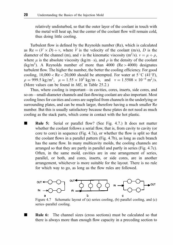
j Rule 5: Serial or parallel ¯ow? (See Fig. 4.7.) It does not matter
whether the coolant follows a serial ¯ow, that is, from cavity to cavity (or
core to core) in sequence (Fig. 4.7a), or whether the ¯ow is split so that
the coolant ¯ows in a parallel pattern (Fig. 4.7b), as long as each branch
has the same ¯ow. In many multicavity molds, the cooling channels are
arranged so that they are partly in parallel and partly in series (Fig. 4.7c).
Often, in the same mold, cavities are in one arrangement of series,
parallel, or both, and cores, inserts, or side cores, are in another
arrangement, whichever is more suitable for the layout. There is no rule
for which way to go, as long as the ¯ow rules are followed.
j Rule 6: The channel sizes (cross sections) must be calculated so that
there is always more than enough ¯ow capacity in a preceding section to
Figure 4.7 Schematic layout of (a) series cooling, (b) parallel cooling, and (c)
series±parallel cooling.
20 Understanding the Basics of the Injection Mold
feed equally all the channels in the following split, parallel sections. For
example, if there are 4 parallel channels of 40 mm2 cross-sectional area
each, the (preceding) feeder must have at least 4� 40 mm2 � 160 mm2
cross-sectional area. In some molds there are 4 or more points where the
cross sections step down in the cooling system. It does not matter if the
preceding section is greater than the calculated minimum value, but it
must not be smaller, if the coolant is to ¯ow equally through all
subsequent channels. Coolant, like plastics, always takes the path of least
resistance. For example, if the preceding cross section is 3x, and each of 4
succeeding parallel cross sections are x, there will not be enough coolant,
and one of the 4 channels will see little or no ¯ow through it.
Unfortunately, this is often missed in designs and the mold does not
function properly.
j Rule 7: The dif®cult-to-cool areas in the mold must be considered ®rst.
These are, essentially, all delicate mold features, such as thin and slender
core pins, blades, and sleeves. Slender signi®es, in this context, that the
ratio of length over the narrow bottom dimension or diameter of a pin or
insert is more than 2 to 1. Remember that heat always ¯ows from the
higher toward the lower temperature; the ¯ow decreases as the length of
travel increases and as the cross-sectional area through which the heat
travels gets smaller. Dif®cult-to-cool areas limit the mold cooling
capability and seriously affect the molding cycle. There is no sense in
providing good cooling for the easy-to-cool areas of the mold if there are
poorly cooled areas elsewhere in it. Selecting materials such as
beryllium±copper alloys may help to remove the heat faster, or special
cooling methods may be used, such as blowing (cold) air at the thin
sections while the mold is open. But ®rst the designer must try to ®nd a
way of getting coolant (not necessarily water) into the thin sections, or at
least get the best cooling into the mold parts supporting these thin
projections.
j Rule 8: Study the product to locate heavy sections of the plastic. They
are always a problem, even where it is easy to provide good cooling,
because of potential shrink and sink marks. Heavy sections are
particularly bad if they are toward the end of the plastics ¯ow where
there is less pressure to ensure good ®lling. The mold designer should
discuss this problem with the product designer. There may be the
possibility of a minor alteration of the product design to avoid heavy
sections so that not only is plastic saved but also cooling time is reduced.
For example, the heavy, solid handle of a coffee mug could be redesigned
4.8 Cooling 21

by coring it from both sides. This could add to the mold cost, but would
greatly reduce the cycle time. The question is whether the customer wants
to sacri®ce design features for productivity. (See also Understanding
Product Design for Injection Molding.)
4.8.2 Plate Cooling
An often overlooked fact is that mold cooling is not only for cooling the plastic,
but also for cooling the various mold plates that are close to areas heated by the
plastic, such as the hot runner systems discussed later or, in special cases, such
as injection blow molding, where the mold cores are heated to keep the plastic
hot, for blowing immediately after injection. As is explained in Section 4.10, all
materials expand when heated. In many molds, certain plates are essential for
the alignment system because they carry the leader pins and bushings or other
alignment members. If the mold plates are at different temperatures, they will
expand differently from their original, cold state, and cause misalignment
between the alignment elements. For example, assume that the distance of two
leader pins in a mold is L � 400 mm and that a temperature difference of
DT � 10 �C (18 �F) exists between the two plates carrying the pins and
bushings. With an approximate heat expansion for steel of 0.000011 mm/mm/�C,
L will increase by DL. DL � L� DT� 0:000011 � 400� 10 � 0:000011 �0:044 mm (0.00173 inch). Considering that the standard diametrical clearance
between leader pins and bushings is only 0.025 mm (0.001 inch), the example
shows the pins will bend at every cycle, or bind in the bushings. This points
to the importance of ensuring in the design that both mold halves should
be kept as close as possible to the same temperature. (Compression molding,
usually employed for thermosetting materials, requires heating of the mold,
regardless of productivity. In this process, the plastic must be heated to set (or
harden); the product leaves the mold hotter than the raw material used to ®ll the
mold.)
More about cooling later. See also ME, Chapter 13.
4.9 Ejection
After the plastic in the cavity spaces has cooled suf®ciently and is rigid enough
and ready for removal, the mold halves move apart, allowing suf®cient space
22 Understanding the Basics of the Injection Mold

between the mold halves for removal of the product. As with cooling, the
complexity of any provision for ejection from the mold is a question of the
desired productivity. Some products don't need any provision within the mold
for ejection. For example, a quick blast from an air jet applied manually by an
operator and directed at the parting line can lift a (simple) product off the core or
out of the cavity, but this would not be practical in most molds, and is rarely
used for real production. Usually, the products are ejected by one of the
following methods:
(1) Pin (and sleeve)
(2) Stripper plate or stripper ring
(3) Air alone
(4) Air assist
(5) Combination of any of the above (1), (2), (3), and (4)
(6) Unscrewing, in case of screw caps, etc.
(7) Combination of any of the above, combined with robots
The most common and oldest methods are
� Pin (and sleeve) as shown in Fig. 4.8
� Stripper plate or stripper ring, as shown in Fig. 4.9
These two systems can be used in most molds and for most plastics. The
problem with both these systems is that there are heavy moving parts
involved, and the upkeep of such molds is high.
� Air ejection alone can be used for ¯at products (Fig. 4.10, left), but for
deep cup-shaped products (right) it is restricted to only certain plastics
and shapes. The main advantage is that it has no, or almost no, moving
Figure 4.8 (Left) Section through ejector pin mold: (a) backing plate, (b) ejector plate,
(c) ejector retainer plate, (d) core plate, (e) molded product, (f) ejector pin, (g) stop pin.
(Right) Section through sleeve ejector mold: (a) backing plate, (b) core pin retainer
plate, (c) ejector plate, (d) sleeve retainer plate, (e) molded product, (f) core plate, (g)
sleeve ejector, (h) core pin, (i) stop pin.
4.9 Ejection 23
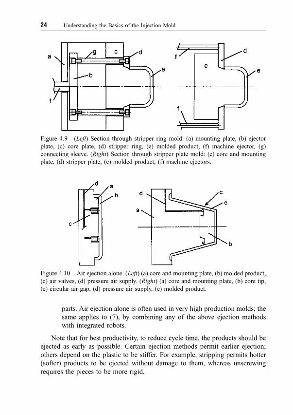
parts. Air ejection alone is often used in very high production molds; the
same applies to (7), by combining any of the above ejection methods
with integrated robots.
Note that for best productivity, to reduce cycle time, the products should be
ejected as early as possible. Certain ejection methods permit earlier ejection;
others depend on the plastic to be stiffer. For example, stripping permits hotter
(softer) products to be ejected without damage to them, whereas unscrewing
requires the pieces to be more rigid.
Figure 4.10 Air ejection alone. (Left) (a) core and mounting plate, (b) molded product,
(c) air valves, (d) pressure air supply. (Right) (a) core and mounting plate, (b) core tip,
(c) circular air gap, (d) pressure air supply, (e) molded product.
Figure 4.9 (Left) Section through stripper ring mold: (a) mounting plate, (b) ejector
plate, (c) core plate, (d) stripper ring, (e) molded product, (f) machine ejector, (g)
connecting sleeve. (Right) Section through stripper plate mold: (c) core and mounting
plate, (d) stripper plate, (e) molded product, (f) machine ejectors.
24 Understanding the Basics of the Injection Mold

4.9.1 Automatic Molding
Earlier molds were all designed to require operators (often lowly paid and
unskilled) to sit or stand at the molding machine. After every cycle they opened
the safety gate to remove the products from the molding area, reclosed the gate
and initiated the next molding cycle. They also were, in some cases, supposed to
visually inspect the products at this time and even make adjustments to the
machine if they thought it necessary. Because the molds were often not properly
®nished, by today's standards, or had unreliable injection and ejection systems,
the operator was also often required to reach into the molding area to pry loose a
stuck, possibly defective product, and from time to time had to lubricate the
molding surfaces with mold release agents. All this was not only labor intensive,
adding greatly to the cost of production, but was also very unsafe and the cause
of many serious injuries. Since much of this operation also depended on the
acquired skill of the operatorÐsome workers are faster, some slowerÐand on
the time of the day or night, or even on the day of the week, the overall molding
cycle time could vary considerably, resulting in quality differences of the
product because of different residence times of the melt in the machine; many
rejects resulted. There was also the problem of absenteeism of the personnel,
which often played havoc with production planning. Much effort was therefore
spent on eliminating operators from the actual molding process.
Fully automatic (FA) molding depends essentially on two factors:
(1) Reliable injection. The molding machine must be repetitive from cycle
to cycle in every aspect, but especially in the dosing (the amount of
plastic injected) and the melt temperature.
(2) Reliable ejection. This is 100% the responsibility of the mold designer.
Every mold (with very rare exceptions) can be designed so that there is
no chance of the product hanging up and not ejecting. The key to good
ejection is that the product always stays on the side from which it will
be ejected, usually, but not necessarily, from the core side of the mold.
The designer must select the appropriate method of ejection and make
sure that there is enough ejection stroke to clear the products from the
cores. This is frequently overlooked and can also be caused by
improper setup of the mold. Many areas must be considered in the
design; some are discussed later.
The designer must keep in mind Murphy's law, which says that if it can happen,
it will.
See also ME, Chapter 12.
4.9 Ejection 25
4.10 Shrinkage
One of the most misunderstood areas of mold design is shrinkage. Every
material (metals, plastics, gases, liquids) expands as its temperature increases
(heat expansion) and returns to its original volume if cooled down to the original
temperature. The problem with all plastics is the characteristic of compressi-
bility. All solid materials compress under load, but most not as much as plastics.
When pressure is applied to plastics (or to hydraulic oil, but not to water),
plastics will compress signi®cantly (i.e., reduce in volume) in proportion to the
amount of pressure applied. This may be (within the range of molding
operations) as high as 2% of the original volume. Thus, we now have two
conditions that work against each other: heat expansion and compressibility. As
the plastic is injected, it is both hot and therefore expanded, but also under
signi®cant pressure, which reduces its volume. This makes it very dif®cult to
arrive at a true shrinkage factor, because the actual change in volume depends
on the type of plastic, the melt temperature, the injection pressure required to
®ll the cavity space, and the temperature at which it will be ejected from the
mold.
For practical purposes, and for many products and molds, the shrinkage
factors supplied by materials suppliers can be used. However, these ®gures
indicate only a range within which to choose, usually between 0 and 5%. In
some cases, where the volume or size of a product is important, this is not
accurate enough. With crystalline plastics, such as polyethylene (PE),
polypropylene (PP), and polyamide (nylon), the shrinkage factor is much
higher than with amorphous plastics, such as polystyrene (PS) and
polycarbonate (PC). Plastics ®lled with inert substances, such as glass or
carbon ®bers or talcum, have a much lower shrinkage than that for the same but
un®lled material. Shrinkage ®gures should be obtained from materials suppliers,
for guiding purposes.
4.10.1 Variable Shrinkage
The designer must understand that the areas within the cavity spaces close to the
gate see higher pressures, so the shrinkage there will be less and will require a
smaller shrinkage factor. Conversely, near the end of the ¯ow through the
narrow cavity space, the pressure in the plastic is much lower than near the gate,
and a higher shrinkage factor will apply. In some applications, more than two
26 Understanding the Basics of the Injection Mold
shrinkage factors may have to be selected within one cavity. It is also important
to establish at what temperature the product will be ejected. If it is ejected while
still hot, it will shrink more outside of the cavity space as it cools to room
temperature. If ejected later, when it is cooler, it will shrink less, as measured in
comparison with the steel sizes of the cavity and core.
This is sometimes, but uneconomically, used to arrive at the proper size of a
product such as a container or lid. If a molded product is too small because not
enough shrinkage value was added to the product dimensions when specifying
the mold steel dimensions, the proper product size can be achieved by ejecting it
later, when it is cooler, but this means loss in productivity. With high production,
the proper procedure is to resize the steel dimensions.
See also ME, Chapter 8.
4.11 Alignment
Various methods are used to align cavity and core plates. The method selected
depends on the shape of the product, the accuracy (or tightness of tolerances)
of the product, and even on the expected mold life. Several choices are
available:
(1) No provision for alignment within the mold
(2) Leader pins and bushings
(3) Taper lock between each cavity and core
(4) Taper lock between a group of cavities and cores
(5) Wedge locks
(6) Taper pins
(7) Combination of (2) with (3), (4), (5), or (6)
4.11.1 No Provision for Alignment
In the case of a ¯at product, without any cavity (depression) in one mold half,
and the cavity entirely in the other mold half, for example, in a mold for a ¯oor
mat, there is no need for alignment, even if there is some engraving on the ¯at
surface of the mold, because the most the dimensions can vary is by the amount
of play between the machine tie bars and the tie bar bushings.
4.11 Alignment 27
4.11.2 Leader Pins and Bushings
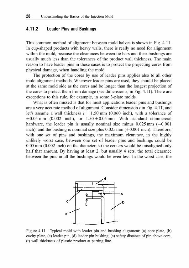
This common method of alignment between mold halves is shown in Fig. 4.11.
In cup-shaped products with heavy walls, there is really no need for alignment
within the mold, because the clearances between tie bars and their bushings are
usually much less than the tolerances of the product wall thickness. The main
reason to have leader pins in these cases is to protect the projecting cores from
physical damage, when handling the mold.
The protection of the cores by use of leader pins applies also to all other
mold alignment methods. Wherever leader pins are used, they should be placed
at the same mold side as the cores and be longer than the longest projection of
the cores to protect them from damage (see dimension s, in Fig. 4.11). There are
exceptions to this rule, for example, in some 3-plate molds.
What is often missed is that for most applications leader pins and bushings
are a very accurate method of alignment. Consider dimension t in Fig. 4.11, and
let's assume a wall thickness t � 1:50 mm (0.060 inch), with a tolerance of
�0:05 mm (0.002 inch), or 1.50� 0.05 mm. With standard commercial
hardware, the leader pin is usually nominal size minus 0.025 mm (ÿ0:001
inch), and the bushing is nominal size plus 0.025 mm (�0.001 inch). Therefore,
with one set of pins and bushings, the maximum clearance, in the highly
unlikely worst case, between one set of leader pins and bushings could be
0.05 mm (0.002 inch) on the diameter, so the centers would be misaligned only
half that amount. By having at least 2, but usually 4 sets, the total clearance
between the pins in all the bushings would be even less. In the worst case, the
Figure 4.11 Typical mold with leader pin and bushing alignment: (a) core plate, (b)
cavity plate, (c) leader pin, (d) leader pin bushing, (s) safety distance of pin above core,
(t) wall thickness of plastic product at parting line.
28 Understanding the Basics of the Injection Mold
possible play and misalignment would be well within the tolerance limits
speci®ed in this example, and therefore acceptable.
It can be easily seen that this holds true as long as the product has not much
smaller wall thicknesses, as is often the case with thin-wall containers, with wall
thicknesses in the order of 0.4 mm (0.015 inch) or even less. In those special but
frequent cases, other methods of alignment must be used such as taper ®ts. We
also must not forget the in¯uence of heat expansion of the mold plates, which
will affect the alignment accuracy.
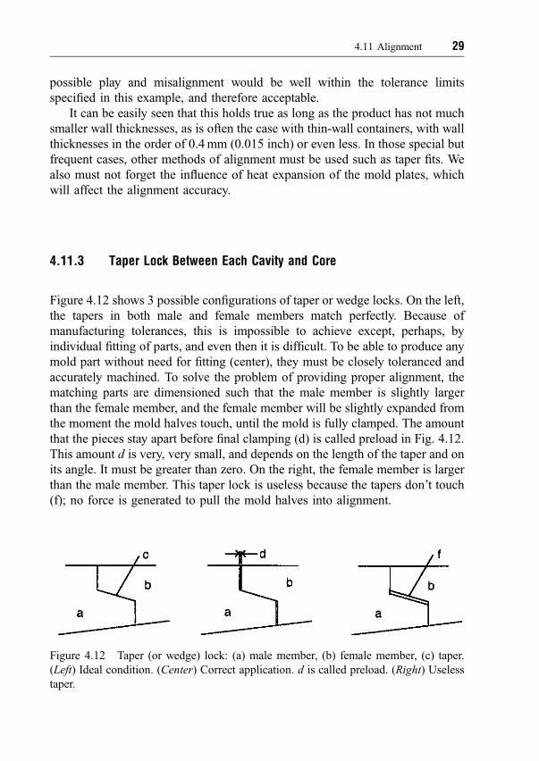
4.11.3 Taper Lock Between Each Cavity and Core
Figure 4.12 shows 3 possible con®gurations of taper or wedge locks. On the left,
the tapers in both male and female members match perfectly. Because of
manufacturing tolerances, this is impossible to achieve except, perhaps, by
individual ®tting of parts, and even then it is dif®cult. To be able to produce any
mold part without need for ®tting (center), they must be closely toleranced and
accurately machined. To solve the problem of providing proper alignment, the
matching parts are dimensioned such that the male member is slightly larger
than the female member, and the female member will be slightly expanded from
the moment the mold halves touch, until the mold is fully clamped. The amount
that the pieces stay apart before ®nal clamping (d) is called preload in Fig. 4.12.
This amount d is very, very small, and depends on the length of the taper and on
its angle. It must be greater than zero. On the right, the female member is larger
than the male member. This taper lock is useless because the tapers don't touch
(f); no force is generated to pull the mold halves into alignment.
Figure 4.12 Taper (or wedge) lock: (a) male member, (b) female member, (c) taper.
(Left) Ideal condition. (Center) Correct application. d is called preload. (Right) Useless
taper.
4.11 Alignment 29

In practice, it can be easily seen on a mold if the tapers work: If the tapers (or
wedges) are shiny all around, they work; if they are rusty, or just dirty, they don't
work, and the mold probably depends on the tie bars and tie bar bushings for
alignment, or on the mold leader pins and bushings. It is surprising how many
molds are in this category. Many times the designer (or the mold maker) thought
that by providing tapers, the mold will be more accurately aligned. In most of
these cases, the taper ®t was wasted money. Note that working tapers are subject
to severe wear and must be made from suitable, hardened steels, and even so will
have to be replaced or repaired from time to time. Any size taper is acceptable,
between 5 and 20 �. (Common tapers are 7, 10, and 15 �.) Too small a taper may
cause locking and separation dif®culty because of friction in the tapers; too
large a taper requires too much force to close. Obviously, to move the tapers
for the preload distance d, until they seat properly, means that the matching,
female taper will have to be spread. This requires considerable force. When
considering the clamp force of the machine, this must be considered and the
forces calculated, especially with multicavity molds in which every stack is
aligned with taper locks. If too much force is required for closing the mold, there
may not be enough clamp force left for holding the mold closed during
injection.
4.11.4 Taper Locks and Wedges
Taper locks are conical (usually round) matching mold parts, and the taper of the
cone is designed to provide the alignment between two mold parts (cavity±core,
core±stripper ring, etc.). This method is very accurate and relatively
inexpensive, but has two inherent disadvantages:
(1) The alignment of the various components depends on the accuracy of
machining and once the assembly is ®nished, there is no possibility of
adjusting the alignment.
(2) Once the tapers wear, which is unavoidable due to the very nature of
this design, which must touch and rub, they are dif®cult to repair and
reuse without changing other mold parts as well. The easiest way is
often to replace the worn elements.
Wedges are pairs of hardened, ¯at bars, with one side tapered. Four sets of
wedges are always required per alignment, either for each cavity, or for the
whole mold. The advantage is that wedges can be shimmed or ground on
30 Understanding the Basics of the Injection Mold
opposite pairs to adjust for wear or for inaccurate manufacturing, or easily
replaced if shimming is not practical. The disadvantage of wedges is that they
require more space on the mold surface, so the mold size will be larger than
when using taper locks.
4.11.5 Taper Pins
Taper pins (and bushings) are sometimes used for the ®nal alignment of cavity
and core in addition to leader pins, where it is believed that the accuracy of
leader pins is insuf®cient. They act similarly to taper locks and are available as
standard mold hardware. It is questionable whether they do any better job than
the other methods of alignments explained here; and they are subject to the same
problems as taper locks, regarding wear and accuracy of machining the mold
and/or core plates.
4.11.6 Too Many Alignment Features
Another problem is frequently encountered in poorly designed molds. Typically,
cavities and cores can be aligned by either leader pins and bushings, or taper (or
wedge) locks. Where high accuracy in alignment is required, taper (or wedge)
locks are the preferred choice. However, they do not assure that the mold halves
will stay together when handling the mold; there is always the danger that the
cores and cavities could be damaged if the mold halves should separate and
bang together once the taper engagement is lost. It is therefore necessary to
equip the mold with leader pins (but not necessarily with leader pin bushings),
in addition to the taper locks. Since the tapers will determine the ®nal alignment,
the leader pins must ®t only loosely in their corresponding openings (or leader
pin bushings) without actually contributing to the ®nal alignment of cavities and
cores. Quite often, even for large molds, only two such pins need to be provided,
usually located at the top of the mold on the core side.
Similarly, some multicavity molds are built with small leader pins (usually
only two) and bushings for each set of cavity and core and are mounted on the
stack plates; they ensure the ®nal alignment of each stack. In addition, two or
four large leader pins are used to align the complete mold halves, but these pins
also must be `̀ loose'' in their bushings, to prevent `̀ ®ghting'' between the two
4.11 Alignment 31
separate sets of alignments. An exception to this rule of loose pins is when a
more expensive but superior method is used: the cores are mounted such that
they can move slightly (¯oat) on their backing plates; as the mold closes, the
®nal alignment (tapers or pins) will move each core into position relative to its
cavity. In this case, the leader pins mounted in the mold shoe (on the core side)
will have their regular, standard clearances.
32 Understanding the Basics of the Injection Mold
Related Documents