4 Pumping of liquids 4.1 Pumps and pumping Pumps are devices for supplying energy or head to a flowing liquid in order to overcome head losses due to friction and also, ifnecessary, to raise the liquid to a higher level. The head imparted to a flowing liquid by a pump is known as the total head Ah. If a pump is placed between points 1 and 2 in a pipeline, the heads for steady flow are related by equation 1.14 In equation 1.14, z, P/(pg), and u2/(2ga) are the static, pressure and velocity heads respectibely and hf is the head loss due to friction. The dimensionless velocity distribution factor CY is 4 for laminar flow and approximately 1 for turbulent flow. For a liquid of density p flowing with a constant mean velocity u through a pipeline of circular cross section and constant diameter between points 1 and 2 separated by a pump, equation 1.14 can be written as Pg (4.1) For the most part, pumps can be classified into centrifugal and positive displacement pumps. 4.2 System heads The important heads to consider in a pumping system are the suction, discharge, total and available net positive suction heads. The following definitions are given in reference to the typical pumping system shown in Figure 4.1 where the arbitrarily chosen base line is the centre-line of the pump. 140

Welcome message from author
This document is posted to help you gain knowledge. Please leave a comment to let me know what you think about it! Share it to your friends and learn new things together.
Transcript

4 Pumping of liquids
4.1 Pumps and pumping
Pumps are devices for supplying energy or head to a flowing liquid in order to overcome head losses due to friction and also, ifnecessary, to raise the liquid to a higher level. The head imparted to a flowing liquid by a pump is known as the total head Ah. If a pump is placed between points 1 and 2 in a pipeline, the heads for steady flow are related by equation 1.14
In equation 1.14, z, P/(pg), and u2/(2ga) are the static, pressure and velocity heads respectibely and hf is the head loss due to friction. The dimensionless velocity distribution factor CY is 4 for laminar flow and approximately 1 for turbulent flow.
For a liquid of density p flowing with a constant mean velocity u through a pipeline of circular cross section and constant diameter between points 1 and 2 separated by a pump, equation 1.14 can be written as
Pg (4.1)
For the most part, pumps can be classified into centrifugal and positive displacement pumps.
4.2 System heads
The important heads to consider in a pumping system are the suction, discharge, total and available net positive suction heads. The following definitions are given in reference to the typical pumping system shown in Figure 4.1 where the arbitrarily chosen base line is the centre-line of the pump.
140
PUMPING O F LIQUIDS 141
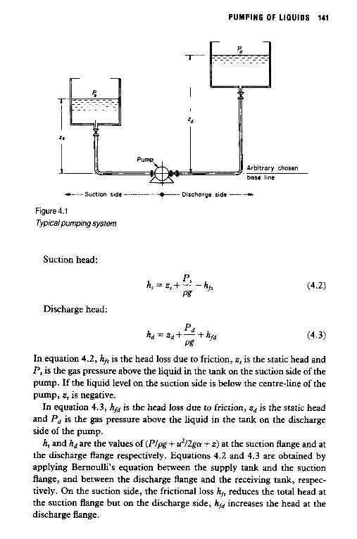
-Suction side ___$__ Discharge side - Figure 4.1 Typical pumping system
Suction head:
p, h, = z,+- -hrs Pg
Discharge head:
In equation 4.2, hfs is the head loss due to friction, z, is the static head and P, is the gas pressure above the liquid in the tank on the suction side of the pump. If the liquid level on the suction side is below the centre-line of the pump, z, is negative.
In equation 4.3, hfd is the head loss due to friction, z d is the static head and p d is the gas pressure above the liquid in the tank on the discharge side of the pump.
h, and hd are the values of (Plpg + u2/2gcy + z) at the suction flange and at the discharge flange respectively. Equations 4.7. and 4.3 are obtained by applying Bernoulli’s equation between the supply tank and the suction flange, and between the discharge flange and the receiving tank, respec- tively. On the suction side, the frictional loss hfi reduces the total head at the suction flange but on the discharge side, hfd increases the head at the discharge flange.
1 4 2 FLUID FLOW FOR C H E M I C A L E N G I N E E R S
The total head Ah which the pump is required to impart to the flowing liquid is the difference between the discharge and suction heads:
A h z h d - h , (4.4)
Equation 4.4 can be written in terms of equations 4.2 and 4.3 as
The head losses due to friction are given by the equations
and
(4.6)
(4.7)
where CL, , and Z L , d are the total equivalent lengths on the suction and discharge sides of the pump respectively.
The suction head h, decreases and the discharge head hd increases with increasing liquid flow rate because of the increasing value of the friction head loss terms hfi and b d . Thus the total head Ah which the pump is required to impart to the flowing liquid increases with the liquid pumping rate.
It is clear from equation 4.2 that the suction head h, can fall to a very low value, for example when the suction frictional head loss is high and the static head z, is low. If the absolute pressure in the liquid at the suction flange falls to, or below, the absolute vapour pressure Pv of the liquid, bubbles of vapour will be formed at the pump inlet. Worse still, even if the pressure at the suction flange is slightly higher than the vapour pressure, cavitation-the formation and subsequent collapse of vapour bubbles- will occur within the body of the pump because the pressure in the pump falls further as the liquid is accelerated.
In order that cavitation may be avoided, pump manufacturers specify a minimum value by which the total head at the suction flange must exceed the head corresponding to the liquid's vapour pressure.
The difference between the suction head and the vapour pressure head is known as the Net Positive Suction Head, NPSH:
D J V NPSH=h,-- Pg
(4.8)

PUMPING OF Ll l lUlOS 143
Substituting for h, from equation 4.2, the available NPSH is given by
(4.9) p, - p7J NPSH = z,+ ~ - hfi
Pg
The available NPSH given by equations 4.8 and 4.9 must exceed the value required by the pump and specified by the manufacturer. The required NPSH increases with increasing flow rate as discussed below.
4.3 Centrifugal pumps
In centrifugal pumps, energy or head is imparted to a flowing liquid by centrifugal action. The most common type of centrifugal pump is the volute pump. In volute pumps, liquid enters near the axis of a high speed impeller and is thrown radially outward into a progressively widening spiral casing as shown in Figure 4.2. The impeller vanes are curved to
Figure Volute
Discharge
4.2 centrifugal pump casing design

144 FLUID FLOW F O R C H E M I C A L E N G I N E E R S
ensure a smooth flow of liquid. The velocity head imparted to the liquid is gradually converted into pressure head as the velocity of the liquid is reduced. The efficiency of this conversion is a function of the design of $he impeller and casing and the physical properties of the liquid.
The performance of a centrifugal pump for a particular rotational speed of the impeller and liquid viscosity is represented by plots of total head against capacity, power against capacity, and required NPSH against capacity. These are known as characteristic curves of the pump. Charac- teristic curves have a variety of shapes depending on the geometry of the impeller and pump casing. Pump manufacturers normally supply these curves only for operation with water. However, methods are available for plotting curves for other viscosities from the water curves [Holland and Chapman (1966)l.
The most common shape of a total head against capacity curve for a conventional volute centrifugal pump is shown in Figure 4.3, where Ah is the total head developed by the pump and Q is the volumetric flow rate of liquid or capacity. The maximum total head developed by the pump is at zero capacity. As the liquid throughput is increased, the total head developed decreases. The pump can operate at any point on the Ah against Q curve. Any individual Ah against Q curve is only true for a particular rotational speed of the impeller and liquid viscosity. As the liquid viscosity increases the Ah against Q curve becomes steeper. Thus the shaded area in Figure 4.3 increases as the liquid viscosity increases.
The total head Ah developed by a centrifugal pump at a particular capacity Q is independent of the liquid density. Thus the higher the density of the liquid, the higher the pressure hp developed by the pump. The relationship between AI' and Ah is given by equation 4.10
AI' = pAhg (4.10)
Thus if a centrifugal pump develops a total head of 100 m when pumping a liquid of density p = 1000 kg/m3, the pressure developed is 981 000 Pa; while for p = 917 kg/m3 the pressure developed is 900000 Pa.
Equation 4.10 shows that when a centrifugal pump runs on air, the pressure developed is very small. In fact, a conventional centrifugal pump can never prime itself when operating on a suction lift.
In a particular system, a centrifugal pump can only operate at one point on the Ah against Q curve and that is the point where the pump Ah against Q curve intersects with the system Ah against Q curve as shown in Figure 4.4.
Equation 4.5 gives the system total head at a particular liquid flow rate.

PUMPING OF LIQUIDS 145
(7-
Figure 4.3 Total head against capacity characteristic curve for a volute centrifugal pump
Combining equation 4.5 with equations 4.6 and 4.7, which give the frictional head losses hfi and hfd respectively, allows the total head to be written as
The mean velocity u of the liquid is related to the volumetric flow rate or capacity Q by
Q u=- ~ d f l 4
Substituting for u in equation 4.11 gives
from (1.6)

1 4 6 FLUID FLOW FOR C H E M I C A L ENGINEERS
For laminar flow, the Fanning friction factor f is given by equation 2.15
16 Re
f = - (2.15)
Substituting for f i n equation 4.12, the total head for laminar flow can be written as
or as
The system Ah against Q curve shown in Figure 4.4 can be plotted using equation 4.12 to calculate the values of the system total head Ah at each volumetric flow rate of liquid or capacity Q. Equation 4.14 shows that for laminar flow the total head Ah increases linearly with capacity Q. Thus for laminar flow, the system Ah against Q curve is a straight line.
0-
Figure 4.4 System andpump total head against capacity curves. The intersection of the two curves defines the operating point

PUMPING OF L i a u i o s 147
/ /
Available NPSH in the system
I cn z n
,/ by the pump
a- Figure 4.5 Available and required net positive suction heads against capacity in a pumping system
In the above discussion it is assumed that the available NPSH in the system is adequate to support the flow rate of liquid into the suction side of the pump. If the available NPSH is less than that required by the pump, cavitation occurs and the normal curves do not apply. In cavitation, some of the liquid vaporizes as it flows into the pump. As the vapour bubbles are carried into higher pressure regions of the pump they collapse, resulting in noise and vibration. High speed pumps are more prone to cavitation than low speed pumps.
Figure 4.5 shows a typical relationship between the available NPSH in the system and the NPSH required by the pump as the volumetric flow rate of liquid or capacity Q is varied. The NPSH required by a centrifugal pump increases approximately with the square of the liquid throughput. The available NPSH in a system can be calculated from equation 4.9 having substituted for hfi
Equation 4.15 shows that the available NPSH in a system decreases as the liquid throughput increases because of the greater frictional head losses.
148 FLUID FLOW FOR CHEMICAL ENGINEERS
Normal pump curve for odequate suction condition
4 I
.E ‘ I I
“ I ! /Normal oocratina \ I / point .
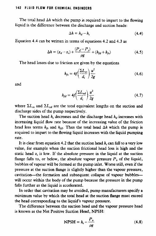
0- Figure 4.6 Effect of insufficient NPSH on the performance of a centrifugal pump
A centrifugal pump will operate normally at a point on its total head against capacity characteristic curve until the available NPSH falls below the required NPSH curve. Beyond t h i s point, the total head generated by a centrifugal pump falls drastically as shown in Figure 4.6 as the pump begins to operate in cavitation conditions.
In centrifugal pump systems, a throttling valve is located on the discharge side of the pump. When this valve is throttled, the system Ah against Q curve is altered to incorporate the increased frictional head loss. The effect of throttling is illustrated in Figure 4.7. Throttling can be used to decrease cavitation. A flow regulating valve or other constriction must not be placed on the suction side of the pump.
System total heads should be estimated as accurately as possible. Safety factors should never be added to these estimated total head values. This is illustrated by Figure 4.8. Suppose that OA, is the correct curve and that the centrifugal pump is required to operate at point AI. Let a safety factor be added to the total head values to give a system curve OA2. On the basis of curve OAz, the manufacturer will supply a pump to operate at point A*. However, since the true system curve is OAl , the pump will operate at point A 3 . Not only is the capacity higher than that specified, but the pump motor may be overloaded.

PUMPING OF L iau ios 149
1 0-
Figure 4.7 Effect of throttling the discharge valve on the operating point of a centrifugal pump
0-
Figure 4.8 Effect of adding a safety factor to the system total head against capacity curve

150 FLU10 FLOW FOR CHEMICAL ENGINEERS
Example 4.1 Calculate the values for a system total head against capacity curve for the initial conditions of the system shown in Figure 4.1 given the following data:
dynamic viscosity of liquid density of liquid static head on suction side of pump static head on discharge side of pump inside diameter of pipe pipe roughness gas pressure above the liquid in the tank
on the suction side of the pump gas pressure above the liquid in the tank
on the discharge side of the pump total equivalent length on the suction
side of the pump total equivalent length on the discharge
side of the pump
Calculations
initially take
p = 0.04 Pa s p = 1200 kg/m3 z , = 3 m Zd=7m di = 0.0526 m e = 0.000045 m
P, = atmospheric pressure
P d = atmospheric pressure
ZL,, = 4.9 m
pudi Reynolds number Re = - P
p = 1200 kg/m3
u = 1.0 m/s
di = 0.0526 m
p = 0.04 Pa s
(1200 kg/m3>(l.0 m/s)(0.0526 m) 0.04 Pa s
Re = = 1578
pipe roughness e = 0.000045 m
di = 0.0526 m
e 0.000045m di 0.0526m
relative roughness - = = 0.000856
fromfagainst Re graph in Figure 2.1

PUMPING OF m u m 151
e f= 0.0112 for Re = 1578 and - = 0.000856
di
(ZLe5 + xLed) 4.9 m + 63.2 m = 1294.7 - -
di 0.0526 m
u2 (l.Om/S)2 = 0.05097 m _ - -
2g (2)(9.81 m/s2)
= 4 m + 4(0.0112)(1294.7)(0.05097 m)
= 6.671 m
Q mean velocity u = - irdf/4
rdf (3.142)(0.0526 m)’ = 0.002173 m2 - - -
4 4
rdf capacity Q = u __
4
= (1 .O m/s)(0.002173 m2)
= 0.002173 m3/s = 0.00217 m3/s
Repeating the calculations for other values of u gives the following results:
Table 4.1
u Re ji’2 u2/2g 4f (ZL,,+ZL ) u2
m / S m m [ di ] 0.5 789 0.01014 0.01274 1.338 1.0 1578 0.00506 0.05097 2.671
2.0 3 156 0.0052 0.2039 10.98 2.5 3945 0.0050 0.3186 16.50 3.0 4734 0.0048 0.4487 22.31
1.5 2367 - 0.1149 -
Ah m
Q m3/s
5.3 6.7
15.0 20.5 26.3
-
0.001 09 0.002 17 0.003 26 0.004 35 0.005 44 0.006 53
At u = 1.5 m/s the flow is transitional and no reliable value can be given to f.
152 F L U I D FLOW FOR CHEMICAL ENGINEERS
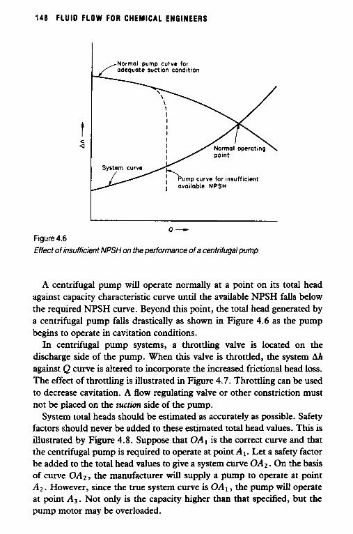
4.4 Centrifugal pump relations
The power PE required in an ideal centrifugal pump can be expected to be a function of the liquid density p, the impeller diameter D and the rotational speed of the impeller N. If the relationship is assumed to be given by the equation
p E = C ~ O N (4.16)
then it can be shown by dimensional analysis [Holland and Chapman ( 1966)] that
PE = ClpN3D5 (4.17)
where C 1 is a constant which depends on the geometry of the system.
rate Q and the total head Ah developed by the pump. The power PE is also proportional to the product of the volumetric flow
PE = C2QAh (4.18)
where Cz is a constant. The volumetric flow rate Q and the total head Ah developed by the
pump are related to the rotational speed of the impeller N and the impeller diameter D by equations 4.19 and 4.20 respectively:
Q = C&D3 (4.19)
Ah = C.$12D2 (4.20)
where C3 and C4 are constants. Note that equation 4.20 is dimensionally consistent only if C4 has the
dimensions T2/L and consequently the numerical value of C4 is different for different sets of units.
Eliminating D between equations 4.19 and 4.20 allows the following result to be obtained:
N r n Ah3,4 = a constant (4.21)
The constant in equation 4.21 is known as the Specific Speed N , of the pump. Although commonly used, this definition of the specific speed is unsatisfactory because, following from equation 4.20, the value of N, depends on the units used. Moreover, manufacturers sometimes mix the units. When using specific speed data it is essential to know the definition of N , and the units of N , Q and h employed.

PUMPING OF LIQUIDS 153
A more satisfactory definition is that of a dimensionless specific speed N >. The above deficiency can be removed by replacing equation 4.20 by equation 4.22:
gAh = C ’ a 2 D 2 (4.22)
where C b is a dimensionless constant. The dimensionless specific speed N > is given by
N r n (gAh)3’4
N : = (4.23)
The value of N > is a unique number provided that consistent units are used. In SI units, the units are N in reds, Q in m3/s, h in m, and g has the value 9.81 d s 2 . The specific speed is used as an index of pump types and is always evaluated at the best efficiency point (bep) of the pump.
Two different size pumps are said to be geometrically similar when the ratios of corresponding dimensions in one pump are equal to those of the other pump [Holland and Chapman (1966)l. Geometrically similar pumps are said to be homologous. A set of equations known as the affinity laws govern the performance of homologous centrifugal pumps at various impeller speeds.
Consider a centrifugal pump with an impeller diameter D1 operating at a rotational speed N1 and developing a total head A h l . Consider an homologous pump with an impeller diameter D2 operating at a rotational speed Nz and developing a total head A h 2 .
Equations 4.19 and 4.22 (or 4.20) for this case can be rewritten respectively in the form
= (x) and
Similarly equation 4.17 can be rewritten in the form
D1 P E 2
(4.24)
(4.25)
(4.26)
and by analogy with equation 4.25 the net positive suction heads for the two homologous pumps can be related by the equation

154 FLUID FLOW FOR CHEMICAL ENGINEERS
(4.27)
Equations 4.24 to 4.27 are the affinity laws for homologous centrifugal pumps.
For a particular pump where the impeller of diameter D1 is replaced by an impeller with a slightly different diameter D 2 , the following equations hold [Holland and Chapman (1966)l:
and
(4.28)
(4.29)
(4.30)
If the characteristic performance curves are available for a centrifugal pump operating at a given rotation speed, equations 4.28 to 4.30 enable the characteristic performance curves to be plotted for other operating speeds and for other slightly different impeller diameters.
Example 4.2 A volute centrifugal pump with an impeller diameter of 0.02 m has the following performance data when pumping water at the best efficiency point:
impeller speed N
capacity Q = 0.012 m3/s
total head Ah = 70m
= 58.3 reds
required net positive suction head NPSH = 18m
brake power Pe = 12000w
Evaluate the performance characteristics of a homologous pump with twice the impeller diameter operating at half the impeller speed.
Calculations Let subscripts 1 and 2 refer to the first and second pumps respectively.

PUMPING OF LIQUIDS 155
The ratio of impeller spreeds N I N z = 2 and the ratio of impeller diameters D1/Dz = 1/2. The ratio of capacities is given by
"=($)(El) 3
Q2
= (2)(&) = a The capacity of the second pump is
Qz = 4Q1 = (4)(0.012 m3/s)
= 0.048 m3/s
The ratio of total heads is
The total head of the second pump is
Ahz = Ahl = 70 m -
The ratio of powers is
(4.24)
(4.25)
(4.26)
Assume
Then
(This is equivalent to assuming that the two pumps operate at the same efficiency.)
The power for the second pump is given by
Pe2 4PB, = (4)(12000 W) = 48000 W

156 FLUID FLOW FOR CHEMICAL ENGINEERS
The ratio of required net positive suction heads is
NPSHl ’ D1 ’ NPSH2 - is:) (z) -- -
= (4)(f) = 1
Therefore net positive suction head of second pump
NPSH2 = NPSHl = - 18 m
(4.27)
4.5 Centrifugal pumps in series and in parallel
Diskind (1959) determined the operating characteristics for centrifugal pumps in parallel and in series using a simple graphical method.
Consider two centrifugal pumps in parallel as shown in Figure 4.9. The
L----- AhT-
Pump curve (11
I I I I I I
01 4 or a-
Figure 4.9 Operating point for centrifugal pumps in parallel
PUMPING OF LIQUIDS 157
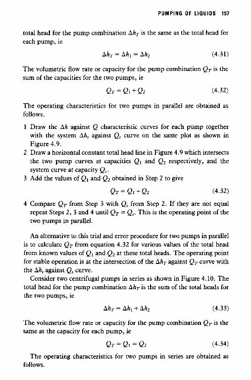
total head for the pump combination AhT is the same as the total head for each pump, ie
AhT = Ah1 = Ah2 (4.31)
The volumetric flow rate or capacity for the pump combination QT is the sum of the capacities for the two pumps, ie
QT = Q I + Q2 (4.32)
The operating characteristics for two pumps in parallel are obtained as follows.
1 Draw the Ah against Q characteristic curves for each pump together with the system Ah, against Q, curve on the same plot as shown in Figure 4.9.
2 Draw a horizontal constant total head line in Figure 4.9 which intersects the two pump curves at capacities Q1 and Q2 respectively, and the system curve at capacity Q, .
3 Add the values of Ql and Q2 obtained in Step 2 to give
QT = 91 + Q2 (4.32)
4 Compare QT from Step 3 with Q, from Step 2. If they are not equal repeat Steps 2 , 3 and 4 until QT = Q,. This is the operating point of the two pumps in parallel.
An alternative to this trial and error procedure for two pumps in parallel is to calculate QT from equation 4.32 for various values of the total head from known values of Q1 and Q2 at these total heads. The operating point for stable operation is at the intersection of the AhT against QT curve with the Ah, against Q, curve.
Consider two centrifugal pumps in series as shown in Figure 4.10. The total head for the pump combination AhT is the sum of the total heads for the two pumps, ie
AhT = Ah1 + Ah2 (4.33)
The volumetric flow rate or capacity for the pump combination Q T is the same as the capacity for each pump, ie
Q T = Q I = Q2 (4.34)
The operating characteristics for two pumps in series are obtained as follows.

158 FLUID FLOW FOR CHEMICAL ENGINEERS
I I I I I
Q- Q,
Figure 4.1 0 Operating point for centrifugal pumps in series
1 Draw the Ah against Q characteristic curves for each pump together with the system Ah3 against Q, curve on the same plot as shown in Figure 4.10.
2 Draw a vertical constant capacity line in Figure 4.10 which intersects the two pump curves at total heads Ah, and Ahz respectively, and the system curve at total head Ahs.
3 Add the values of Ah, and Ahz obtained in Step 2 to give
AhT = Ah, + Ah2 (4.33)
4 Compare AhT from Step 3 with Ah, from Step 2 . If they are not equal repeat Steps 2, 3 and 4 until AhT = Ah,. This is the operating point of the two pumps in series.
PUMPING OF L i a u i o s 159
An alternative to this trial and error procedure for two pumps in series is to calculat: AhT from equation 4.33 for various values of the capacity from known values of Ah, and Ah2 at these capacities. The operating point for stable operation is at the intersection of the AhT against QT curve with the Ahs against Qs curve.
The piping and valves may be arranged to enable two centrifugal pumps to be operated either in series or in parallel. For two identical pumps, series operation gives a total head of 2Ah at a capacity Q and parallel operation gives a capacity of 2 Q at a total head Ah. The efficiency of either the series or parallel combination is practically the same as for a single Pump-
4.6 Positive displacement pumps
For the most part, positive displacement pumps can be classified either as rotary pumps or as reciprocating pumps. However, pumps do exist which exhibit some of the characteristics of both types.
Rotary pumps forcibly transfer liquid through the action of rotating gears, lobes, vanes, screws etc, which operate inside a rigid container. Normally, pumping rates are varied by changing the rotational speed of the rotor. Rotary pumps do not require valves in order to operate.
Reciprocating pumps forcibly transfer liquid by changing the internal volume of the pump. Pumping rates are varied by altering either the frequency or the length of the stroke. Valves are required on both the suction and discharge sides of the pump.
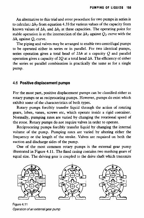
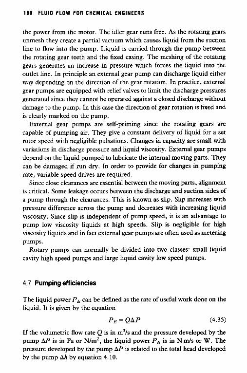
One of the most common rotary pumps is the external gear pump illustrated in Figure 4.11. The !ked casing contains two meshing gears of equal size. The driving gear is coupled to the drive shaft which transmits
Figure 4.1 1 Operation of an external gear pump
160 FLUID FLOW FOR CHEMICAL ENGINEERS
the power from the motor. The idler gear runs free. As the rotating gears unmesh they create a partial vacuum which tames liquid from the suction line to flow into the pump. Liquid is carried through the pump between the rotating gear teeth and the fixed casing. The meshing of the rotating gears generates an increase in pressure which forces the liquid into the outlet line. In principle an external gear pump can discharge liquid either way depending on the direction of the gear rotation. In practice, external gear pumps are equipped with relief valves to limit the discharge pressures generated since they cannot be operated against a closed discharge without damage to the pump. In this case the direction of gear rotation is fixed and is clearly marked on the pump.
External gear pumps are self-priming since the rotating gears are capable of pumping air. They give a constant delivery of liquid for a set rotor speed with negligible pulsations. Changes in capacity are small with variations in discharge pressure and liquid viscosity. External gear pumps depend on the liquid pumped to lubricate the internal moving parts. They can be damaged if run dry. In order to provide for changes in pumping rate, variable speed drives are required.
Since close clearances are essential between the moving parts, alignment is critical. Some leakage occurs between the discharge and suction sides of a pump through the clearances. This is known as slip. Slip increases with pressure difference across the pump and decreases with increasing liquid viscosity. Since slip is independent of pump speed, it is an advantage to pump low viscosity liquids at high speeds. Slip is negligible for high viscosity liquids and in fact external gear pumps are often used as metering pumps.
Rotary pumps can normally be divided into two classes: small liquid cavity high speed pumps and large liquid cavity low speed pumps.
4.7 Pumping efficiencies
The liquid power PE can be defined as the rate of useful work done on the liquid. It is given by the equation
P E = QAP (4.35)
If the volumetric flow rate Q is in m3/s and the pressure developed by the pump AP is in Pa or N/m2, the liquid power P E is in N d s or W. The pressure developed by the pump AP is related to the total head developed by the pump Ah by equation 4.10.

PUMPING O F L IQUIDS 161
h P = p A h g (4.10)
Substituting equation 4.10 into equation 4.35 gives
P E = P Q A h g (4.36)
which can also be written as
PE = M A h g (4.37)
since M = pQ is the mass flow rate. If M is in kg/s, Ah is in m and the gravitational accelerating g = 9.81 d s ’ , P E is in W.
The brake power PB can be defined as the actual power delivered to the pump by the prime mover. It is the sum of liquid power and power lost due to friction and is given by the equation
(4.38)
where 7 is the mechanical efficiency expressed in per cent. The mechanical efficiency decreases as the liquid viscosity and hence
the frictional losses increase. The mechanical efficiency is also decreased by power losses in gears, bearings, seals etc. In rotary pumps contact between the rotor and the fixed casing increases power losses and decreases the mechanical efficiency. These losses are not proportional to pump size. Relatively large pumps tend to have the best efficiencies whilst small pumps usually have low efficiencies. Furthermore, high speed pumps tend to be more efficient than low speed pumps. In general, high efficiency pumps have high NPSH requirements. Sometimes a comprom- ise may have to be made between efficiency and NPSH.
Another efficiency which is important for positive displacement pumps is the volumetric efficiency. This is the delivered capacity per cycle as a percentage of the true displacement per cycle. If no slip occurs, the volumetric efficiency of the pump is 100 per cent. For zero pressure difference across the pump, there is no slip and the delivered capacity is the true displacement. The volumetric efficiency of a pump is reduced by the presence of entrained air or gas in the pumped liquid. It is important to know the volumetric efficiency of a positive displacement pump when it is to be used for metering.

162 FLUID FLOW FOR CHEMICAL ENGINEERS
4.8 Factors in pump selection
The selection of a pump depends on many factors which include the required rate and properties of the pumped liquid and the desired location of the pump.
In general, high viscosity liquids are pumped with positive displace- ment pumps. Centrifugal pumps are not only very inefficient when pumping high viscosity liquids but their performance is very sensitive to changes in liquid viscosity. A high viscosity also leads to high frictional head losses and hence a reduced available NPSH. Since the latter must always be greater than the NPSH required by the pump, a low available NPSH imposes a severe limitation on the choice of a pump. Liquids with a high vapour pressure also reduce the available NPSH. If these liquids are pumped at a high temperature, this may cause the gears to seize in a close clearance gear pump.
If the pumped liquid is shear thinning, its apparent viscosity will decrease with an increase in shear rate and hence pumping rate. It is therefore an advantage to use high speed pumps to pump shear thinning liquids and in fact centrifugal pumps are frequently used. In contrast, the apparent viscosity of a shear thickening liquid will increase with an increase in shear rate and hence pumping rate. It is therefore an advantage to use large cavity positive displacement pumps with a low cycle speed to pump shear thickening liquids.
Some liquids can be permanently damaged by subjecting them to high shear in a high speed pump. For example, certain liquid detergents can be broken down into two phases if subject to too much shear. Even though these detergents may exhibit shear thinning characteristics they should be pumped with relatively low speed pumps.
Wear is a more serious problem with positive displacemeni pumps than with centrifugal pumps. Liquids with poor lubricating qualities increase the wear on a pump. Wear is also caused by corrosion and by the pumping of liquids containing suspended solids which are abrasive.
In general,-centrifugal pumps are less expensive, last longer and are more robust than positive displacement pumps. However, they are unsuitable for pumping high viscosity liquids and when changes in viscosity occur.

PUMPING O F L IQUIDS 163
References
Diskind, T., Solve muliple hookups graphically, Chemical Engineering, 66 p. 102
Holland, F.A. and Chapman, F.S., Pumping ofliquids, New York, Reinhold (2 Nov 1959).
Publishing Corporation (1966).
Related Documents