© LINDY ELECTRONICS LIMITED & LINDY-ELEKTRONIK GMBH - FIRST EDITION (July 2012) 4-in-1 Crimp & Cable Tester Tool User Manual English Benutzerhandbuch Deutsch Manuel Utilisateur Français Manuale d’uso Italiano LINDY No. 43206 www.lindy.com

Welcome message from author
This document is posted to help you gain knowledge. Please leave a comment to let me know what you think about it! Share it to your friends and learn new things together.
Transcript

© LINDY ELECTRONICS LIMITED & LINDY-ELEKTRONIK GMBH - FIRST EDITION (July 2012)
4-in-1 Crimp & Cable Tester Tool
User Manual English Benutzerhandbuch Deutsch Manuel Utilisateur Français Manuale d’uso Italiano
LINDY No. 43206 www.lindy.com

English User Manual
1
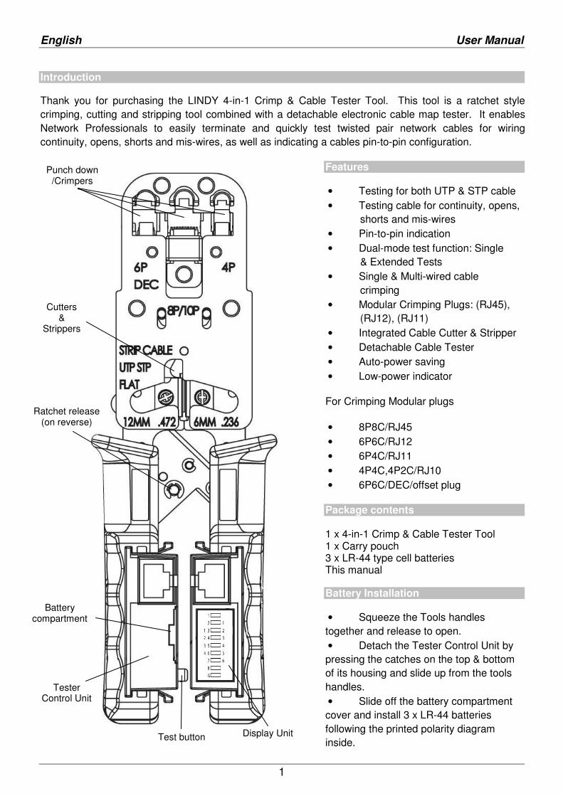
Introduction
Thank you for purchasing the LINDY 4-in-1 Crimp & Cable Tester Tool. This tool is a ratchet style crimping, cutting and stripping tool combined with a detachable electronic cable map tester. It enables Network Professionals to easily terminate and quickly test twisted pair network cables for wiring continuity, opens, shorts and mis-wires, as well as indicating a cables pin-to-pin configuration.
Features
• Testing for both UTP & STP cable • Testing cable for continuity, opens, shorts and mis-wires • Pin-to-pin indication • Dual-mode test function: Single & Extended Tests • Single & Multi-wired cable crimping • Modular Crimping Plugs: (RJ45), (RJ12), (RJ11) • Integrated Cable Cutter & Stripper • Detachable Cable Tester • Auto-power saving • Low-power indicator
For Crimping Modular plugs
• 8P8C/RJ45 • 6P6C/RJ12 • 6P4C/RJ11 • 4P4C,4P2C/RJ10 • 6P6C/DEC/offset plug
Package contents 1 x 4-in-1 Crimp & Cable Tester Tool 1 x Carry pouch 3 x LR-44 type cell batteries This manual
Battery Installation
• Squeeze the Tools handles together and release to open. • Detach the Tester Control Unit by pressing the catches on the top & bottom of its housing and slide up from the tools handles. • Slide off the battery compartment cover and install 3 x LR-44 batteries following the printed polarity diagram inside.
Punch down /Crimpers
Cutters &
Strippers
Ratchet release (on reverse)
Tester Control Unit
Display Unit Test button
Battery compartment
English User Manual
3
Tool operation
To open the tool, squeeze the handles together and release.
To lock the handles closed - for storage - squeeze the handles together to final 6thratchet and release.
To Strip & Terminate Cable
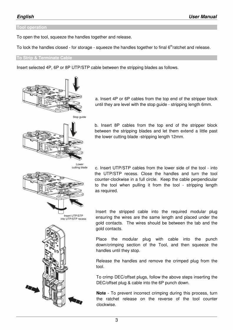
Insert selected 4P, 6P or 8P UTP/STP cable between the stripping blades as follows.
a. Insert 4P or 6P cables from the top end of the stripper block until they are level with the stop guide - stripping length 6mm.
b. Insert 8P cables from the top end of the stripper block between the stripping blades and let them extend a little past the lower cutting blade -stripping length 12mm.
c. Insert UTP/STP cables from the lower side of the tool - into the UTP/STP recess. Close the handles and turn the tool counter-clockwise in a full circle. Keep the cable perpendicular to the tool when pulling it from the tool - stripping length as required.
Insert the stripped cable into the required modular plug ensuring the wires are the same length and placed under the gold contacts. The wires should be between the tab and the gold contacts.
Place the modular plug with cable into the punch down/crimping section of the Tool, and then squeeze the handles until they stop.
Release the handles and remove the crimped plug from the tool.
To crimp DEC/offset plugs, follow the above steps inserting the DEC/offset plug & cable into the 6P punch down.
Note - To prevent incorrect crimping during this process, turn the ratchet release on the reverse of the tool counter clockwise.
Stop guide
Lower cutting blade
Insert UTP/STP into UTP/STP recess
English User Manual
2
Cable Testing
Plug one end of the cable to be tested into the Tester Control Unit and the other end into the Tester Display Unit. Due to their smaller size, when testing 6P6C, 6P4C cables ensure they are plugged firmly into each of the Testing Units.
Quick Test - Press the Test button on the Control Unit to start the test.
Extended Test - Press & hold the Test button for 3 seconds and then release. The Tester will repeat the single test 12 times.
To stop the Extended Test at any time simply press the Test button again.
The Test Units will power off automatically when the testing process has completed.
Low Battery Indicator - LED #1 will flash when the Test button is pressed.
Note - The LEDs may not light up in a sequential order depending on the mapping of the cable tested.
Detaching the Cable Testers
Squeeze the handles of the Tool together and release to open.
Detach the Test Units by pressing the catches on the top & bottom of their housing and slide up from the tools handles.
Reverse the steps above to reattach the Test Units.
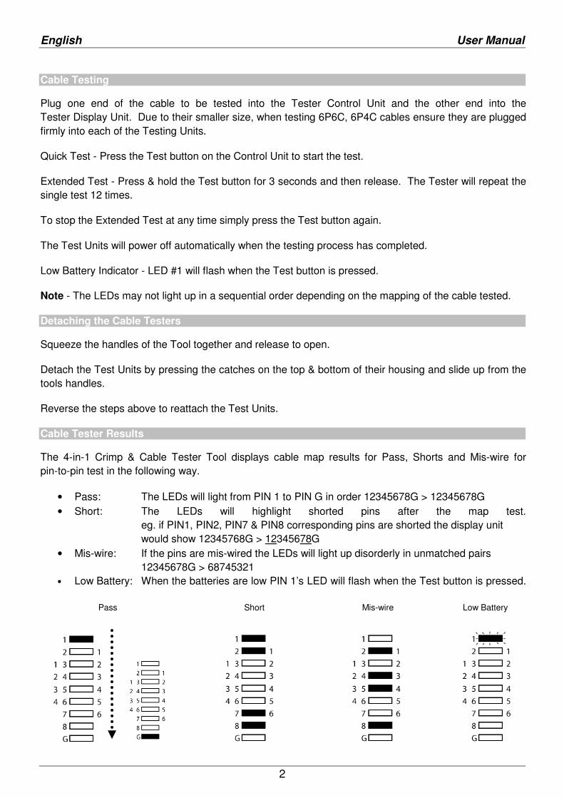
Cable Tester Results
The 4-in-1 Crimp & Cable Tester Tool displays cable map results for Pass, Shorts and Mis-wire for pin-to-pin test in the following way.
• Pass: The LEDs will light from PIN 1 to PIN G in order 12345678G > 12345678G • Short: The LEDs will highlight shorted pins after the map test.
eg. if PIN1, PIN2, PIN7 & PIN8 corresponding pins are shorted the display unit would show 12345768G > 12345678G
• Mis-wire: If the pins are mis-wired the LEDs will light up disorderly in unmatched pairs 12345678G > 68745321
• Low Battery: When the batteries are low PIN 1’s LED will flash when the Test button is pressed. Pass Short Mis-wire Low Battery
Deutsch Benutzerhandbuch
3
Einleitung
Herzlichen Dank für den Erwerb des LINDY 4-in-1 Crimp- und Kabeltestwerkzeuges. Es handelt sich um ein Crimp- Schneid- und Abisolierwerkzeug, kombiniert mit einem abnehmbaren elektronischen Kabeltester, und ermöglichet Netzwerktechnikern ein professionelles und schnelles terminieren und von Twisted –Pair-Netzwerkkabeln und deren einfaches Testen auf Durchgängigkeit, offene Adern, Kurzschlüsse, sowie das Ermitteln der Pinbelegungen.
Merkmale
• Testet sowohl UTP, wie auch STP- Kabel • Testet Kabel auf for Durchgang, offene Adern, Kurzschlüsse und falsches Pinout • Durchgangsanzeige pinweise • Zwei Test-Modi: einfach und erweitert • Crimpmöglichkeit für Modular- stecker RJ45, RJ12 und RJ11 • Integriertes Schneide- und Abmantel werkzeug • Kabeltester abnhembar • Automatischer Stromsparmodus • Anzeige für niedrigen Batteriestatus Zum Crimpen folgender Modularstecker: • 8P8C/RJ45 • 6P6C/RJ12 • 6P4C/RJ11 • 4P4C,4P2C/RJ10 • 6P6C/DEC/Offset-Stecker
Lieferumfang
1 x 4-in-1 Crimp- und Kabeltestwerkzeug 1 x Tragebeutel 3 x LR-44 Knopfzellen-Batterien Dieses Handbuch
Einlegen der Batterien
• Drücken Sie die Zangengriffe des Werkzeuges gegeneinander und lassen Sie sie los, um sie zu öffnen • Lösen Sie den Tester durch Drücken der Rastfedern an der Ober- und Unterseite des Gehäuses und Abziehen des Testers von den Werkzeuggriffen.
• Ziehen Sie den Batteriefachdeckel ab und legen Sie die 3 LR-44-Batterien nach dem innenseitig aufgedruckten Schema ein.
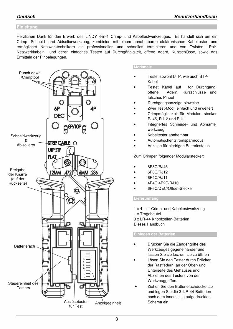
Punch down /Crimptool
Schneidwerkzeug &
Abisolierer
Freigabe der Knarre
(auf der Rückseite)
Steuereinheit des Testers
Anzeigeeinheit
Batteriefach
Auslösetaster für Test
Deutsch Benutzerhandbuch
2
Werkzeugbenutzung
Zum Öffnen der Zangenbacken drücken Sie die beiden Griffe zusammen und lassen Sie sie wieder los.
Zum Verriegeln der Zange drücken Sie die Zangengriffe bis zur 6. Rastung zusammen.
Kabel abmanteln und terminieren
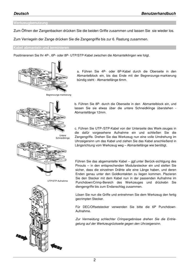
Positinierenen Sie Ihr 4P-, 6P- oder 8P- UTP/STP-Kabel zwischen die Abmantelklingen wie folgt.
a. Führen Sie 4P- oder 6P-Kabel durch die Oberseite in den Abmantelblock ein, bis das Ende mit der Begrenzungs-markierung bündig steht - Abmantellänge 6mm.
b. Führen Sie 8P- durch die Oberseite in den Abmantelblock ein, und lassen Sie sie etwas über die untere Schneidklinge überstehen - Abmantellänge 12mm.
c. Führen Sie UTP-/STP-Kabel von der Unterseite des Werk-zeuges in die dafür vorgesehene Aufnahme ein und schließen Sie die Zangengriffe. Drehen Sie das Werkzeug nun eine volle Umdrehung im Uhrzeigersinn um das Kabel und ziehen Sie das Kabel anschließend in Längsrichtung vom Werkzeug weg – Abmantellänge wie benötigt.
Führen Sie das abgemantelte Kabel – ggf.unter Berück-sichtigung des Pinouts – in den entsprechenden Modularstecker ein und stellen Sie sicher, dass die einzelnen Drähte alle eine Länge haben, und deren Enden genau unter den Goldkontakten zu liegen kommen. Plazieren Sie den Stecker mit dem Kabel nun in der passenden Aufnahme im Punchdown/Crimp-Bereich des Werkzeuges und drückebn Sie diengengriffe bis zum Endanschlag zusammen.
Lösen Sie nun die Griffe und entnehmen Sie dem Werkzeug den fertig gecrimpten Stecker.
Für DEC/Offsetstecker verwenden Sie bitte die 6P Punchdown-Aufnahme.
Zur Vermeidung schlechter Crimpergebnisse drehen Sie die Entrie-
gelung auf der Werkzeugrückseite gegen den Uhrzeigersinn.
Begrenzungs-markierung
Untere Schneidklinge
UTP/STP-Aufnahme
Deutsch Benutzerhandbuch
3
Der Testvorgang
Stecken Sie ein Ende des zu testenden Kabels in die Steuereinheit und das andere in die Anzeigeeinheit. Stellen Sie bei den etwas kleineren 6P6C- oder 6P4C-Kabel deren festen Sitz sicher.
Schnelltest: Drücken Sie den Auslösetaster um den Test zu starten.
Erweiterter Test: Drücken und haltenn Sie den Auslösetaster für ca. 3s. Der Tester ührt den einfachen Schnelltest nun 12 mal hintereinander durch.
Um den erweiterten Test vorzeitig abzubrechen, drücken Sie den Auslösetaster ein zweites Mal.
Nach Abschluss des Testes schaltet sich der Tester automatisch ab.
Bei schwachem Batteriestatus blinkt die LED 1 beim Drücken des Auslösetasters.
Lösen der Kabeltesteinheiten
Drücken Sie die Zangengriffe de sWerkzeuges gegeneinander und lassen Sie sie los, um sie zu öffnen
Lösen Sie den Tester durch Drücken der Rastfedern an der Ober- und Unterseite des Gehäuses und Abziehen des Testers von den Werkzeuggriffen.
Cable Tester Results
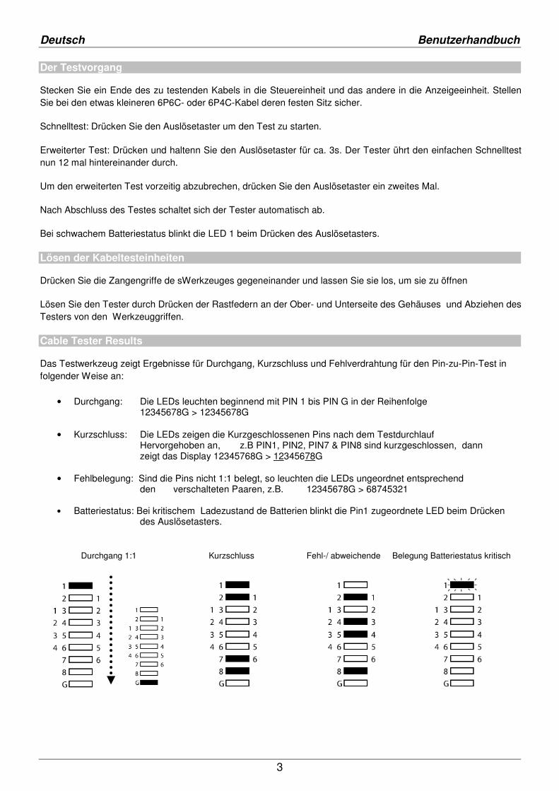
Das Testwerkzeug zeigt Ergebnisse für Durchgang, Kurzschluss und Fehlverdrahtung für den Pin-zu-Pin-Test in folgender Weise an:
• Durchgang: Die LEDs leuchten beginnend mit PIN 1 bis PIN G in der Reihenfolge 12345678G > 12345678G • Kurzschluss: Die LEDs zeigen die Kurzgeschlossenen Pins nach dem Testdurchlauf Hervorgehoben an, z.B PIN1, PIN2, PIN7 & PIN8 sind kurzgeschlossen, dann zeigt das Display 12345768G > 12345678G • Fehlbelegung: Sind die Pins nicht 1:1 belegt, so leuchten die LEDs ungeordnet entsprechend den verschalteten Paaren, z.B. 12345678G > 68745321 • Batteriestatus: Bei kritischem Ladezustand de Batterien blinkt die Pin1 zugeordnete LED beim Drücken
des Auslösetasters. Durchgang 1:1 Kurzschluss Fehl-/ abweichende Belegung Batteriestatus kritisch
Français Manuel Utilisateur
1
Introduction
Merci pour votre achat de cette pince à sertir & testeur 4 en 1 LINDY. Cette pince à sertir à cliquet vous permet également de couper, dégainer et sertir, cela combiné à un testeur de câbles électronique détachable. Il permet aux techniciens des réseaux de facilement préparer et tester les câbles Ethernet avec paires croisées en vérifiant leurs continuités, court-circuit, câbles mal connectés, erreur de câblage, ainsi qu’une indication du brochage pin à pin.
Caractéristiques
• Teste les câbles UTP & STP • Teste continuité, court-circuit,et erreurs de câblage • Indication Pin à Pin • Test Dual-mode test: simple & étendu • Sertissage de câbles mono et multi- brins • Prises: (RJ45), (RJ12), (RJ11) • Pince coupante et à sertir intégrée • Testeur de câbles detachable • Mise en veille automatique • Indication d’usure des piles
Pour le sertissage de prises • 8P8C/RJ45 • 6P6C/RJ12 • 6P4C/RJ11 • 4P4C,4P2C/RJ10 • 6P6C/DEC/offset plug • Package contents
Contenu de l’emballage 1 x pince à sertir&tester 4-in-1 1 x housse de transport 3 x piles boutons LR-44 Ce manuel
Installation des piles
• Serrer les poignées et relâcher pour ouvrir la pince. • Détacher l’unité de test en appuyant
sur les ergots de maintien sur le dessus & dessous et en la faisant glisser hors de son logement. • Ouvrir le compartiment des piles et
installer 3 piles LR-44 en suivant le schémas de polarité.
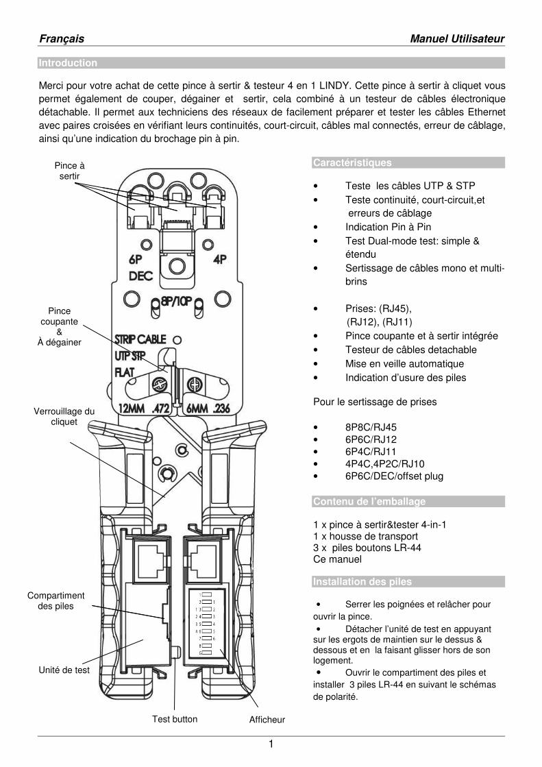
Punch down /Crimpers
Battery compartment
Pince à sertir
Pince coupante
& À dégainer
Verrouillage du cliquet
Compartiment des piles
Unité de test
Afficheur Test button
Français Manuel Utilisateur
3
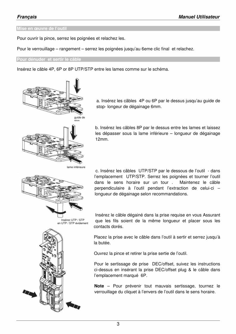
Mise en œuvre de l’outil
Pour ouvrir la pince, serrez les poignées et relachez les.
Pour le verrouillage – rangement – serrez les poignées jusqu’au 6eme clic final et relachez.
Pour dénuder et sertir le câble
Insérez le câble 4P, 6P or 8P UTP/STP entre les lames comme sur le schéma.
a. Insérez les câbles 4P ou 6P par le dessus jusqu’au guide de stop- longeur de dégainage 6mm.
b. Insérez les câbles 8P par le dessus entre les lames et laissez les dépasser sous la lame inférieure – longueur de dégainage 12mm.
c. Insérez les câbles UTP/STP par le dessous de l’outil - dans l’emplacement UTP/STP. Serrez les poignées et tourner l’outil dans le sens horaire sur un tour . Maintenez le câble perpendiculaire à l’outil pendant l’extraction de celui-ci – longueur de dégainage selon recommandations.
Insérez le câble dégainé dans la prise requise en vous Assurant que les fils soient de la même longueur et placer sous les
contacts dorés.
Placez la prise avec le câble dans l’outil à sertir et serrez jusqu’à la butée.
Ouvrez la pince et retirer la prise sertie de l’outil.
Pour le sertissage de prise DEC/offset, suivez les instructions ci-dessus en insérant la prise DEC/offset plug & le câble dans l’emplacement marqué 6P.
Note – Pour prévenir tout mauvais sertissage, tournez le verrouillage du cliquet à l’envers de l’outil dans le sens horaire.
guide de stop
lame inférieure
Insérez UTP / STP en UTP / STP évidement
Français Manuel Utilisateur
1
Test de câbles
Branchez une extrémité du câble à tester dans l’untité de test et l’autre dans l’unité d’affichage. Du à leur plus petite taille, lors de test avec des câbles 6P6C, 6P4C assurez-vous qu’ils soient bien branchés à chaque unité de test.
Test rapide – Appuyez sur le bouton de test sur l’unité de contrôle pour démarrer le test.
Test étendu – Appuyez et maintenez le bouton pendant 3 secondes et relâchez. Le testeur répétera l’opération de test 12 fois.
Pour stopper le test étendu à tout moment, appuyez simplement sur le bouton encore une fois.
Les unités de test seront mises hors tension après la fin du processus de test .
Indication de piles faibles – La LED #1 flash lorsque le bouton de test est appuyé.
Note - Les LED ne s'allumeront pas forcément dans un ordre séquentiel, en fonction du schéma de câblage du câble testé.
Pour détacher les unités de test de leurs supports
Serrez les poignées puis relachez pour ouvrir.
Détachez les unités de test en appuyant sur les ergots de maintien sur le dessus & dessous et en les faisant glisser hors de leurs logements.
Pour remettre les unités de test dans leurs logements réitéré les opérations ci-dessus dans l’ordre inverse.
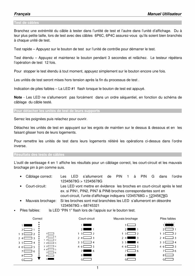
Résultats des tests de câbles
L’outil de sertissage 4 en 1 affiche les résultats pour un câblage correct, les court-circuit et les mauvais brochage pin à pin comme suis.
• Câblage correct: Les LED s’allumeront de PIN 1 à PIN G dans l’ordre 12345678G > 12345678G
• Court-circuit: Les LED vont mettre en évidence les broches en court-circuit après le test ex. si PIN1, PIN2, PIN7 & PIN8 broches correspondantes sont en court-circuit, l’unite d’affichage indiquera 12345768G > 12345678G
• Mauvais brochage: Si les broches sont mal branchées les LED s’allumeront en désordre 12345678G > 68745321
• Piles faibles: la LED “PIN 1” flash lors de l’appuis sur le bouton test.
Correct Court-circuit Mauvais brochage Piles faibles
Italiano Manuale d’uso
1
Introduzione
Grazie per aver scelto la pinza Crimp 4-in-1 & Tester. Questo attrezzo consente di crimpare, tagliare, spelare e testare cavi di rete; include due unità tester removibili per verificare immediatamente la corretta crimpatura di un cavo di rete, se vi sono cricuiti aperti, cortocircuiti e verificare la corretta pinatura.
Caratteristiche
• Testa cavi UTP & STP • Riconosce il corretto pinout, circuiti
aperti e cortocircuiti • Indicatore pin-to-pin • Dual-mode test: Single
& Extended • Crimpatura singola e Multi-wired • Crimpatura di connettori RJ45,
RJ12 e RJ11 • Cutter & spela cavi integrato • 2 unità tester removibili • Modalità power saving automatica • Indicatore batteria scarica
Crimpa i seguenti connettori: • 8P8C/RJ45 • 6P6C/RJ12 • 6P4C/RJ11 • 4P4C,4P2C/RJ10 • 6P6C/DEC/offset plug
Contenuto della confezione 1 x pinza Crimp 4-in-1 & Tester 1 x custodia 3 x batterie LR-44 Questo manuale
Installazione batteria
• Premete e rilasciate le maniglie per aprire la pinza • Togliete le unità di Tester dalle
maniglie della pinza premendo le linguette sopra e sotto ogni unità • Rimuovete la cover
dell’alloggiamento delle batterie ed installate le 3 batterie LR-44 facendo attenzione alla polarità indicata.
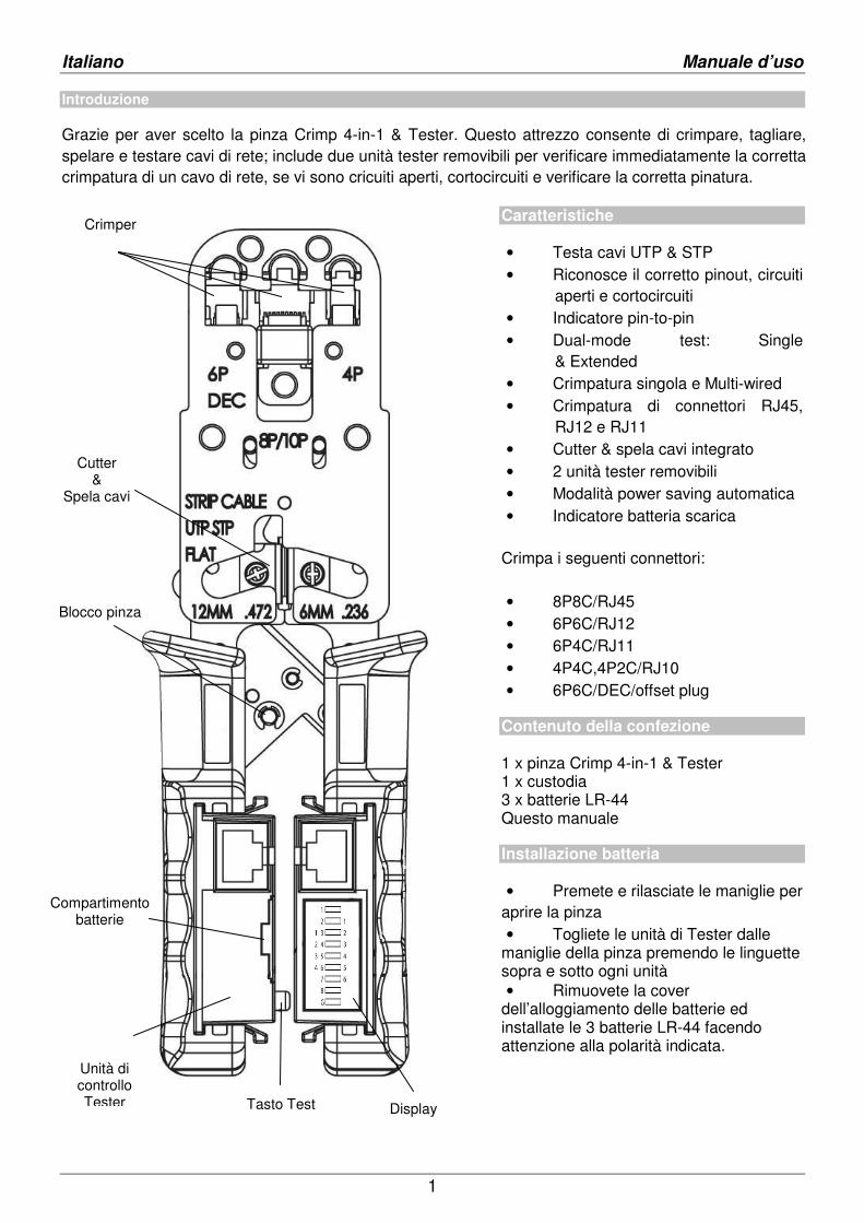
Crimper
Cutter &
Spela cavi
Blocco pinza
Unità di controllo Tester Display Tasto Test
Compartimento batterie
Italiano Manuale d’uso
2
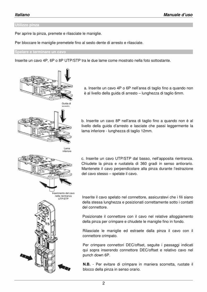
Utilizzo pinza
Per aprire la pinza, premete e rilasciate le maniglie.
Per bloccare le maniglie premetele fino al sesto dente di arresto e rilasciate.
Spelare e terminare un cavo
Inserite un cavo 4P, 6P o 8P UTP/STP tra le due lame come mostrato nella foto sottostante.
a. Inserite un cavo 4P o 6P nell’area di taglio fino a quando non è al livello della guida di arresto – lunghezza di taglio 6mm.
b. Inserite un cavo 8P nell’area di taglio fino a quando non è al livello della guida d’arresto e lasciate che passi leggermente la lama inferiore - lunghezza di taglio 12mm.
c. Inserite un cavo UTP/STP dal basso, nell’apposita rientranza. Chiudete la pinza e ruotatela di 360 gradi in senso antiorario. Mantenete il cavo perpendicolare alla pinza durante l’estrazione del cavo stesso – spelate il cavo.
Inserite il cavo spelato nel connettore, assicuratevi che i fili siano della stessa lunghezza e posizionati correttamente sotto i contatti del connettore.
Posizionate il connettore con il cavo nel relative alloggiamento della pinza per crimpare e chiudete le maniglie fino in fondo.
Rilasciate le maniglie ed estraete dalla pinza il cavo con il connettore crimpato.
Per crimpare connettori DEC/offset, seguite i passaggi indicati qui sopra inserendo connettore DEC/offset e relativo cavo nel punch down 6P.
N.B. - Per evitare di crimpare in maniera scorretta, ruotate il blocco della pinza in senso orario.
Guida di arresto
Lama inferiore
Inserimento del cavo nella rientranza
UTP/STP
Italiano Manuale d’uso
3
Testare cavi
Collegate un capo del cavo da testare nell’unità Control e l’altro capo nell’unità con Display. Considerate le dimensioni ridotte delle unità, quando testiate cavi 6P6C, 6P4C assicuratevi che i connettori siano inseriti correttamente.
Test rapido - Premete il tasto Test sull’unità Control per avviare il test.
Test approfondito – Tenete premuto il tasto Test per 3 secondi e rilasciate; il test verrà ripetuto 12 volte.
Per fermare il test approfondito premete nuovamente il tasto Test.
Le due unità si spegneranno automaticamente una volt anche il test è completato.
Indicatore batteria scarica - LED #1 si accenderà quando viene premuto il tasto Test.
N.B. - I LED potrebbero non accendersi in ordine a seconda della mappatura dei cavi testati.
Rimuovere le unità Tester
Chiudere e rilasciare le maniglie della pinza per aprirle.
Rimuovere le unità del Tester premendo i ganci sopra e sotto ogni unità.
Ripetere gli step sopra indicate nell’ordine opposto per riporre le unità.
Risultati Test cavi
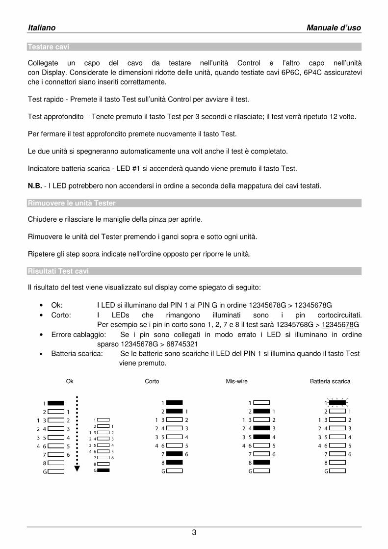
Il risultato del test viene visualizzato sul display come spiegato di seguito:
• Ok: I LED si illuminano dal PIN 1 al PIN G in ordine 12345678G > 12345678G • Corto: I LEDs che rimangono illuminati sono i pin cortocircuitati.
Per esempio se i pin in corto sono 1, 2, 7 e 8 il test sarà 12345768G > 12345678G • Errore cablaggio: Se i pin sono collegati in modo errato i LED si illuminano in ordine
sparso 12345678G > 68745321 • Batteria scarica: Se le batterie sono scariche il LED del PIN 1 si illumina quando il tasto Test
viene premuto. Ok Corto Mis-wire Batteria scarica

CE / FCC Statement
CE Certification
This equipment complies with the requirements relating to Electromagnetic Compatibility Standards and the further standards cited therein. It must be used with shielded cables only.It has been manufactured under the scope of RoHS compliance. CE Konformitätserklärung
Dieses Produkt entspricht den einschlägigen EMV Richtlinien der EU für ITverwendet werden.
Diese Geräte wurden unter Berücksichtigung der RoHS Vorgaben hergestellt.Die formelle Konformitätserklärung können wir Ihnen auf Anforderung zur Verfügung stellen. FCC Certification
This equipment has been tested and found to comply with the limits for a Class B digital device, pursuant to part 15 of the FCC Rules. These limits are designed to provide reasonable protection against harmful interference in a residential installation. This equipmeand can radiate radio frequency energy and, if not installed and used in accordance with the instructions, may cause harmful radio communications. However, there is no guarantee that interference will not occur in a particular installation
Modifications not expressly approved by the manufacturer could void the user's authority to operate the equipment under FCC rOperation is subject to the following two conditions:
1. This device may not cause harmful interference, and2. This device must accept any interference received, including interference that may cause undesired operation.
LINDY Herstellergarantie – Hinweis für Kunden in Deutschland
LINDY gewährt für dieses Produkt über die gesetzliche Regelung in Deutschland hinaus eine zwedetaillierten Bedingungen dieser Garantie finden Sie auf der LINDY Website aufgelistet bei den AGBs.
WEEE (Waste of Electrical and Electronic Equipment), Recycling of Electronic Products
Europe, United Kingdom
In 2006 the European Union introduced regulations (WEEE) for the collection and recycling of all waste electrical and electrono longer allowable to simply throw away electrical and electronic equipment. Instead, these productsEach individual EU member state has implemented the WEEE regulations into national law in slightly different ways. Please follaw when you want to dispose of any electrical or electronic products. More de Germany / Deutschland
Die Europäische Union hat mit der WEEE Direktive Regelungen für die Verschrottung und das Recycling von Elektrogeschaffen. Diese wurden im Elektro- und Elektronikgerätegesetz Entsorgen von entsprechenden, auch alten, ElektroSammelsystemen bzw. örtlichen Sammelstellen zugeführt werden! Dort werden sie kostenlos entgegen genommen. Die Kosten für den weiteren Recyclingprozess übernimmt die Gesamtheit der Gerätehersteller.
France
En 2006, l'union Européenne a introduit la nouvelle réglementation (DEEEChaque Etat membre de l’ Union Européenne a mis en application la nouvelle réglementation DEEE de manières légèrement difféVeuillez suivre le décret d’application correspondant à Italy
Nel 2006 l’unione europea ha introdotto regolamentazioni (WEEE) per la raccolta e il riciclo di apparecchi elettrici ed elettconsentito semplicemente gettare queste apparecchiature, devono essere riciclate. Ogni stato membro dell’ EU ha tramutato le direttive WEEE in leggi statali in varie misure. Fare riferimento alle leggi del proprio Stato quando si dispone di un apparecchio elettricoPer ulteriori dettagli fare riferimento alla direttiva WEEE sul riciclaggio del proprio Stato.
This equipment complies with the requirements relating to Electromagnetic Compatibility Standards EN61326dards cited therein. It must be used with shielded cables only.
It has been manufactured under the scope of RoHS compliance.
Dieses Produkt entspricht den einschlägigen EMV Richtlinien der EU für IT-Equipment und darf nur zusammen
Diese Geräte wurden unter Berücksichtigung der RoHS Vorgaben hergestellt. Die formelle Konformitätserklärung können wir Ihnen auf Anforderung zur Verfügung stellen.
ed and found to comply with the limits for a Class B digital device, pursuant to part 15 of the FCC Rules. These limits are designed to provide reasonable protection against harmful interference in a residential installation. This equipmeand can radiate radio frequency energy and, if not installed and used in accordance with the instructions, may cause harmful radio communications. However, there is no guarantee that interference will not occur in a particular installation
Modifications not expressly approved by the manufacturer could void the user's authority to operate the equipment under FCC rOperation is subject to the following two conditions:
This device may not cause harmful interference, and e must accept any interference received, including interference that may cause undesired operation.
Hinweis für Kunden in Deutschland
LINDY gewährt für dieses Produkt über die gesetzliche Regelung in Deutschland hinaus eine zweijährige Herstellerdetaillierten Bedingungen dieser Garantie finden Sie auf der LINDY Website aufgelistet bei den AGBs.
WEEE (Waste of Electrical and Electronic Equipment), Recycling of Electronic Products
In 2006 the European Union introduced regulations (WEEE) for the collection and recycling of all waste electrical and electrono longer allowable to simply throw away electrical and electronic equipment. Instead, these products must enter the recycling process.Each individual EU member state has implemented the WEEE regulations into national law in slightly different ways. Please follaw when you want to dispose of any electrical or electronic products. More details can be obtained from your national WEEE recycling agency.
Die Europäische Union hat mit der WEEE Direktive Regelungen für die Verschrottung und das Recycling von Elektround Elektronikgerätegesetz – ElektroG in deutsches Recht umgesetzt. Dieses Gesetz verbietet das
Entsorgen von entsprechenden, auch alten, Elektro- und Elektronikgeräten über die Hausmülltonne! Diese Geräte müssen den lokalen chen Sammelstellen zugeführt werden! Dort werden sie kostenlos entgegen genommen. Die Kosten für den
weiteren Recyclingprozess übernimmt die Gesamtheit der Gerätehersteller.
En 2006, l'union Européenne a introduit la nouvelle réglementation (DEEE) pour le recyclage de tout équipement électrique et électronique.Chaque Etat membre de l’ Union Européenne a mis en application la nouvelle réglementation DEEE de manières légèrement difféVeuillez suivre le décret d’application correspondant à l’élimination des déchets électriques ou électroniques de votre pays.
Nel 2006 l’unione europea ha introdotto regolamentazioni (WEEE) per la raccolta e il riciclo di apparecchi elettrici ed elettste apparecchiature, devono essere riciclate. Ogni stato membro dell’ EU ha tramutato le direttive WEEE
in leggi statali in varie misure. Fare riferimento alle leggi del proprio Stato quando si dispone di un apparecchio elettricori dettagli fare riferimento alla direttiva WEEE sul riciclaggio del proprio Stato.
EN61326-1:2006 Class B, EN61326-1:2006
Equipment und darf nur zusammen mit abgeschirmten Kabeln
ed and found to comply with the limits for a Class B digital device, pursuant to part 15 of the FCC Rules. These limits are designed to provide reasonable protection against harmful interference in a residential installation. This equipment generates, uses and can radiate radio frequency energy and, if not installed and used in accordance with the instructions, may cause harmful interference to radio communications. However, there is no guarantee that interference will not occur in a particular installation.
Modifications not expressly approved by the manufacturer could void the user's authority to operate the equipment under FCC rules.
e must accept any interference received, including interference that may cause undesired operation.
ijährige Herstellergarantie ab Kaufdatum. Die
In 2006 the European Union introduced regulations (WEEE) for the collection and recycling of all waste electrical and electronic equipment. It is must enter the recycling process.
Each individual EU member state has implemented the WEEE regulations into national law in slightly different ways. Please follow your national tails can be obtained from your national WEEE recycling agency.
Die Europäische Union hat mit der WEEE Direktive Regelungen für die Verschrottung und das Recycling von Elektro- und Elektronikprodukten ElektroG in deutsches Recht umgesetzt. Dieses Gesetz verbietet das
und Elektronikgeräten über die Hausmülltonne! Diese Geräte müssen den lokalen chen Sammelstellen zugeführt werden! Dort werden sie kostenlos entgegen genommen. Die Kosten für den
) pour le recyclage de tout équipement électrique et électronique. Chaque Etat membre de l’ Union Européenne a mis en application la nouvelle réglementation DEEE de manières légèrement différentes.
l’élimination des déchets électriques ou électroniques de votre pays.
Nel 2006 l’unione europea ha introdotto regolamentazioni (WEEE) per la raccolta e il riciclo di apparecchi elettrici ed elettronici. Non è più ste apparecchiature, devono essere riciclate. Ogni stato membro dell’ EU ha tramutato le direttive WEEE
in leggi statali in varie misure. Fare riferimento alle leggi del proprio Stato quando si dispone di un apparecchio elettrico o elettronico.
LINDY No. 43206
1st Edition July 2012 www.lindy.com
Related Documents