Mitsubishi Heavy Industries Technical Review Vol. 49 No. 4 (December 2012) 28 *1 General Manager, Research & Development Office, Mitsubishi-Hitachi Metals Machinery, Inc. *2 Engineering Manager, Equipment Design Department, Mitsubishi-Hitachi Metals Machinery, Inc. *3 Senior Staff, Sales & Marketing 1 Group, Mitsubishi-Hitachi Metals Machinery, Inc. *4 Hiroshima Research & Development Center, Technology & Innovation Headquarters Development of New Mash Seam Welder (Cross Seam Welder, CSW) Compatible with Continuous Rolling of Steel Sheets at Thicknesses up to 6 mm NORIAKI TOMINAGA *1 HISAYOSI ISHII *2 HIROKI TADOKORO *3 KEIICHI SATOH *4 HIROTOSHI TAGATA *4 YUJIRO WATANABE *4 Today in the steel industry, continuous cold rolling mills with production capacities of 1.5 million tons per year are widely used. Mitsubishi-Hitachi Metals Machinery, Inc. (MH) has created a new continuous cold rolling system to satisfy needs for production capacities of 0.6 to 0.8 million tons per year. To attain such a system, MH has developed a new low-cost mash seam welder (cross seam welder, or CSW) for joining the tail end of the preceding coil and the leading end of the following coil. In order to enable the welding of sheets at thicknesses of up to 6 mm and compatibility with rolling, which cannot be done with conventional a mash seam welder (MSW), the CSW improves the joining ratio of the solid phase bonding line, which was a weak point specific to lap welding, to eliminate weld bead steps. The CSW is being incorporated in our new continuous cold rolling system verification facility and its effectiveness has been verified. | 1. Introduction In the past, continuous cold rolling mills for the steel industry with production capacities of 0.6 to 0.8 million tons per year have used a 2-stand reverse cold mill (2RCM) or two single stand reverse cold mills (RCMs). These reverse cold mills continue rolling until the last pass with the leading and tail ends of the coil wound on the reel. Therefore unrolled portions remaining at the leading and tail ends of the coil are scrapped. The scrapped amount in 2-stand reverse cold mills (2RCM) accounts for about 6.5% of the overall production volume, and about 2.5% for a single stand reverse cold mill (RCM). For improvement of the yield, MH has developed the new continuous cold rolling system (Figure 1), which performs continuous one-way rolling repeatedly until the prescribed thickness is obtained, while circulating the coil. This system can reduce the scrapped amount to 0.3%. The key technologies for this system are continuous one-way rolling, coil circulation, coil build-up, super-low speed rolling and a new mash seam welder (CSW) compatible with rolling described in this document. Figure 1 New continuous cold rolling system

Welcome message from author
This document is posted to help you gain knowledge. Please leave a comment to let me know what you think about it! Share it to your friends and learn new things together.
Transcript

Mitsubishi Heavy Industries Technical Review Vol. 49 No. 4 (December 2012) 28
*1 General Manager, Research & Development Office, Mitsubishi-Hitachi Metals Machinery, Inc. *2 Engineering Manager, Equipment Design Department, Mitsubishi-Hitachi Metals Machinery, Inc. *3 Senior Staff, Sales & Marketing 1 Group, Mitsubishi-Hitachi Metals Machinery, Inc. *4 Hiroshima Research & Development Center, Technology & Innovation Headquarters
Development of New Mash Seam Welder (Cross Seam Welder, CSW) Compatible with Continuous
Rolling of Steel Sheets at Thicknesses up to 6 mm
NORIAKI TOMINAGA*1 HISAYOSI ISHII*2
HIROKI TADOKORO*3 KEIICHI SATOH*4
HIROTOSHI TAGATA*4 YUJIRO WATANABE*4
Today in the steel industry, continuous cold rolling mills with production capacities of 1.5
million tons per year are widely used. Mitsubishi-Hitachi Metals Machinery, Inc. (MH) has created a new continuous cold rolling system to satisfy needs for production capacities of 0.6 to 0.8 million tons per year. To attain such a system, MH has developed a new low-cost mash seam welder (cross seam welder, or CSW) for joining the tail end of the preceding coil and the leading end of the following coil. In order to enable the welding of sheets at thicknesses of up to 6 mm and compatibility with rolling, which cannot be done with conventional a mash seam welder (MSW), the CSW improves the joining ratio of the solid phase bonding line, which was a weak point specific to lap welding, to eliminate weld bead steps. The CSW is being incorporated in our new continuous cold rolling system verification facility and its effectiveness has been verified.
|1. Introduction In the past, continuous cold rolling mills for the steel industry with production capacities of
0.6 to 0.8 million tons per year have used a 2-stand reverse cold mill (2RCM) or two single stand reverse cold mills (RCMs). These reverse cold mills continue rolling until the last pass with the leading and tail ends of the coil wound on the reel. Therefore unrolled portions remaining at the leading and tail ends of the coil are scrapped. The scrapped amount in 2-stand reverse cold mills (2RCM) accounts for about 6.5% of the overall production volume, and about 2.5% for a single stand reverse cold mill (RCM). For improvement of the yield, MH has developed the new continuous cold rolling system (Figure 1), which performs continuous one-way rolling repeatedly until the prescribed thickness is obtained, while circulating the coil. This system can reduce the scrapped amount to 0.3%. The key technologies for this system are continuous one-way rolling, coil circulation, coil build-up, super-low speed rolling and a new mash seam welder (CSW) compatible with rolling described in this document.
Figure 1 New continuous cold rolling system
Mitsubishi Heavy Industries Technical Review Vol. 49 No. 4 (December 2012) 29
Flash butt welders or laser beam welders are currently used for continuous cold rolling mills. However, they are generally large and expensive, and thus unsuitable for this developed new medium-scale continuous cold rolling system. Although conventional mash seam welders (MSW) for the steel industry are low-cost and compact, they are generally used only for low reduction lines such as continuous annealing lines (CAL) or continuous galvanizing lines (CGL). In addition, the maximum acceptable thickness is 4.5 mm and no examples of welding and rolling of thicknesses up to 6 mm – required for rolling lines – have been found. Therefore MH has developed a new mash seam welder (CSW) based on MSW features including low cost and compactness, enhancing its compatibility with rolling and its welding ability. This document describes the tasks in the development of the CSW for use in the new continuous cold rolling system, as well as their completion and results.
|2. Principle of new mash seam welder (CSW) and tasks in its development
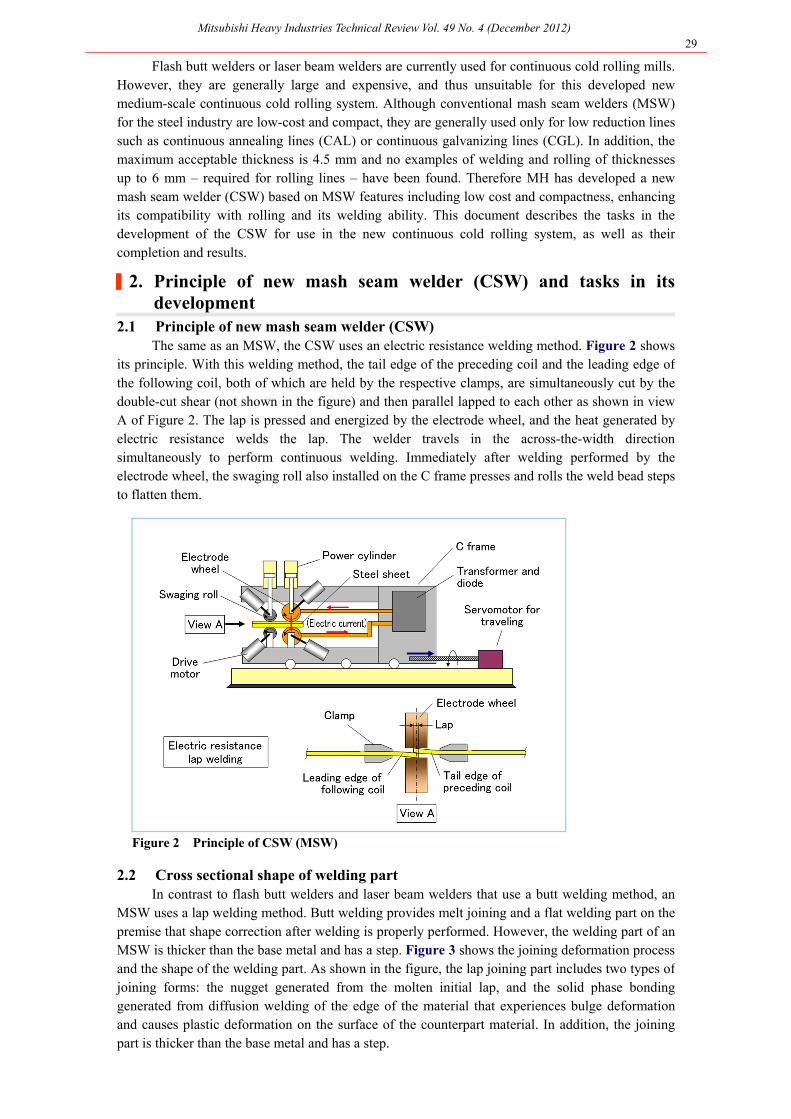
2.1 Principle of new mash seam welder (CSW) The same as an MSW, the CSW uses an electric resistance welding method. Figure 2 shows
its principle. With this welding method, the tail edge of the preceding coil and the leading edge of the following coil, both of which are held by the respective clamps, are simultaneously cut by the double-cut shear (not shown in the figure) and then parallel lapped to each other as shown in view A of Figure 2. The lap is pressed and energized by the electrode wheel, and the heat generated by electric resistance welds the lap. The welder travels in the across-the-width direction simultaneously to perform continuous welding. Immediately after welding performed by the electrode wheel, the swaging roll also installed on the C frame presses and rolls the weld bead steps to flatten them.
Figure 2 Principle of CSW (MSW)
2.2 Cross sectional shape of welding part In contrast to flash butt welders and laser beam welders that use a butt welding method, an
MSW uses a lap welding method. Butt welding provides melt joining and a flat welding part on the premise that shape correction after welding is properly performed. However, the welding part of an MSW is thicker than the base metal and has a step. Figure 3 shows the joining deformation process and the shape of the welding part. As shown in the figure, the lap joining part includes two types of joining forms: the nugget generated from the molten initial lap, and the solid phase bonding generated from diffusion welding of the edge of the material that experiences bulge deformation and causes plastic deformation on the surface of the counterpart material. In addition, the joining part is thicker than the base metal and has a step.

Mitsubishi Heavy Industries Technical Review Vol. 49 No. 4 (December 2012) 30
Figure 3 Joining deformation process and weld example of CSW
2.3 Tasks in development of CSW To use the CSW in a new continuous cold rolling system, the following two tasks, which are
not satisfied by an MSW, must be completed: . The CSW shall be compatible with rolling. . The CSW shall be capable of welding sheets at thicknesses of up to 6 mm.
(1) Compatibility with rolling Although an MSW and other welding methods attain higher strength of welding parts (as
measured by Erichsen tests) than the base metal strength if welding conditions are proper, generally they have not been used in rolling lines. This is because the joining ratio of coils welded by an MSW is low. When a rolling test is performed, the weld bead step is pushed-in by rolling, and then a cracking defect (hereinafter referred to as step push-in defect) occurs and at the same time separation occurs on solid phase bonding. It is assumed that the steps and poor joining ratio of solid phase bonding unique to lap welding cause joint strength deterioration due to rolling deformation. Therefore the enhancement of the joining ratio of solid phase bonding and a method of flattening the weld bead steps has been considered.
(2) Sheet thicknesses up to 6 mm To enable the welding of sheets at thicknesses of up to 6 mm and compatibility with
rolling, the welding conditions and the welding method have been determined based on experiments and analysis, and the specifications of the welder have been readjusted with additional modification of its structure and control.
|3. Enhancement of joining ratio As shown in Figure 3, the material surface and its proximity are welded by solid phase
bonding. Therefore they cannot be satisfactorily jointed unless a certain level of contact pressure and temperature is reached. It is necessary to select welding conditions (such as welding current, electrode force, welding speed, lap, etc.) properly depending on the material and thickness used.
If poorly jointed sheets caused by improper welding conditions are rolled, the solid phase bonding of the surface and its proximity on the bonding line separates off and cracking occurs. This may cause breakage during rolling when the rolling proceeds further and the reduction ratio increases. In regard to the joining ratio, the as-weld evaluation is described below first, and the effect of cross swaging immediately after welding is described later.

Mitsubishi Heavy Industries Technical Review Vol. 49 No. 4 (December 2012) 31
3.1 Influence of welding current and electrode force The most basic welding conditions for the CSW are electrode force and welding current.
Figure 4 shows the results of a welding test (expulsion diagram) of a low carbon steel sheet at an initial thickness of 3.2 mm. All welding conditions are expressed with a facility specification (maximum) of 100% (hereinafter the same shall apply). The joining conditions immediately before the occurrence of expulsion were obtained by maintaining a constant welding speed and enlarging the electrode force and the welding current in incremental steps. Expulsion is blowoff of the molten part of the nugget bursting through its surface layer, and indicates the limit of welding. A cross-sectional macrostructure and microstructure analysis of the welding part was performed and the joining ratio (β[%]) was evaluated. The joining ratio is defined as the following: (For Lt and Lw, refer to Figure 3.)
β = (Lw/Lt) × 100 …(1)
β: Joining ratio Lw: length of the bonded interface jointed with microstructure analysis [mm] Lt: Entire length of the bonded interface [mm]
Items (a) and (b) in Figure 4 are the welding conditions to be compared.
Figure 4 Results of welding test of low carbon steel sheet at thickness of 3.2 mm (expulsion diagram)
Figure 5 shows the relationship between the shape changing ratio (Ct[-]) and the joining
ratio. The shape changing ratio is defined by the following equation:
Ct = (B/tw) / (δ/2to) …(2)
where B: weld width (mm) tw: weld thickness (mm) δ: initial lap (mm) to: base metal thickness (mm)
When electrode force is enhanced, the shape changing ratio increases. Thus the contact area
and welding current can be increased, and the expulsion occurrence limit is improved. This results in improvement of the joining ratio due to temperature increase, even at the edge of bonding line of the steel sheet.
Figure 5 shows a photograph of the as-weld cross-sectional macrostructure. In Figure 5(a), both the electrode force and the welding current are low, and the shape changing ratio is also as low as approximately 6[-]. In this case, there are large steps and a relatively clear solid phase line near of the edge of the steel sheet. On the other hand, in Figure 5(b), the shape changing ratio is as high as approximately 10[-] and the solid phase line at the edge of the steel sheet disappears, and a very

Mitsubishi Heavy Industries Technical Review Vol. 49 No. 4 (December 2012) 32
favorable weld joint with a joining ratio of approximately 100% is obtained. As described above, with regard to the CSW, higher welding current can be used when the
electrode force is enhanced, resulting in an increase of the shape changing ratio and improvement of the joining ratio as shown in the expulsion diagram in Figure 4. Therefore the enlargement of the electrode force and welding current is important.
Figure 5 Shape changing ratio Ct and joining ratio β (t0 = 3.2 mm, SPHC)
3.2 Influence of welding speed The influence of welding speed is complicated. Although it is generally believed that a lower
welding speed enables a higher joining ratio, this does not apply to the CSW. Figure 6 shows an example of this.
Figure 6 Influence of welding speed
The joining ratio for welding a low carbon steel sheet at a thickness of 2 mm is calculated while changing the welding speed with the electrode force and the welding current kept constant. The joining ratio reaches its peak when the speed ratio is 50%, and decreases when the speed ratio is either higher or lower than 50%. The decrease of the joining ratio at a higher welding speed is because of the decrease of the shape changing ratio caused by the shortened welding time. However, when the speed ratio is lower than 50%, the shape changing ratio increases while the joining ratio decreases. This is mainly because heat lost to the electrode wheel has a significant impact. Because the heat lost from the CSW to the electrode wheel is as high as 40 to 50% of the

Mitsubishi Heavy Industries Technical Review Vol. 49 No. 4 (December 2012) 33
total heat amount (described later in the thermal analysis in section 4), it is assumed that the surface of the welding part, which is more susceptible, becomes colder than the center of the welding part, and therefore the joining ratio of the solid-phase bonding line at the surface and its proximity decreases. The photograph of the cross-sectional macrostructure also evidences that the surface temperature at speed ratios of 35% and 40% is lower than that at a speed ratio of 50%. When the speed ratio becomes lower than 50%, the blackening level of the surface and its vicinity on the welding part decreases. This means that the martensite structure that is formed when the material is cooled from a high temperature decreases at a speed rate of 50% or less. When the sheet thickness is thinner, the influence of the welding speed becomes more significant, and therefore it is necessary to find the optimum speed.
|4. Heat balance evaluation To determine the cause of the difference in the joining ratio shown in Figure 5, the
temperature increase of the steel sheet is obtained by the heat balance calculation detailed below. Figure 7 shows an analysis model.
Figure 7 Heat analysis model
For the analysis code, network software (MelTHERFY), where nodes (mass, etc.) are linked by elements (thermal resistance), is used.
Qt
ΔT = ρCpV (B+tw) tw
…(3)
Qt = Qn + Qss + Qse - Qd - Qw …(4)
where ΔT: Temperature increase of steel sheet [°C], Qt: Total heat input [kW], Qn: Heating by internal resistance [kW], Qss: Heating by contact resistance between steel sheets [kW], Qse: Heating by contact resistance between steel sheet and electrode [kW], Qd: Heat lost to electrode [kW], Qw: Heat transfer to steel sheet in width direction [kW], ρ: Density of steel sheet [kg/m3], Cp: Specific heat of steel sheet [J/kg-K], V: Welding speed [m/sec], B: As-weld width [mm], tw: As-weld thickness of steel sheet [mm]
For calculation, the welding shape is measured by a cross-sectional macrostructure
photograph, and the following prerequisites are used: . The current density (i [A/m2]) shall be a constant value obtained by dividing current (I [A]) by the area of the current pass (SB [m2]).

Mitsubishi Heavy Industries Technical Review Vol. 49 No. 4 (December 2012) 34
. The joining width (B [mm]) shall be obtained by measuring the length of the bonded interface on the photograph of the weld point cross-sectional macrostructure. . For the internal resistance of the steel sheet, temperature dependence shall be considered. For contact resistance between steel sheets, temperature dependence and pressure dependence shall be considered.(1) Figure 8 shows the results of the heat balance calculation for the difference of the shape
changing ratio shown in Figure 5. Heat input (Qn+Qss+Qse) of Ct=10[-] in Figure 5(b) is considered as 100%, and heat loss of Qd and Qw is mentioned as negative. The total heat amount (Qt [W]) in Figure 5(a) is 18 [kW]. In Figure 5(b), the electrode force is boosted and the welding current is increased, and therefore the total heat amount increases to approximately 24 [kW]. As a result, the calculated temperature of the solid-phase bonding line and its proximity on the edge of the steel sheet increases from 1023°C to 1300°C. It is assumed that this temperature increase of the solid-phase bonding results in a joining ratio of approximately 100%. The heat lost to the electrode is as large as approximately 40 to 50% of heat input (Qn+Qss+Qse). This is one of the CSW features as described in section 3. Even when the speed is slowed and heat input increases, the temperature of the surface and its proximity to the steel sheet do not always increase.
Figure 8 Calculation result of heat balance (SPHC, 3.2 mm thickness)
Next, to investigate the influence of the welding speed, FEM analysis is performed. Figure 9shows an FEM analysis model (coupled analysis of heat and current). The modeling of the deformation process of the initial lap δ being broadened to width B at the end of welding is performed by dividing with the dotted line. Because in the first half the temperature is lower and therefore the electric resistance of the material is smaller, resulting in higher electric current flow, the current density of the first half shall be twice as large as that of the second half. Figure 10 shows the temperature (Ts) and joining width (B) of the edge (point P) after joining. Both the temperature (Ts) and joining width (B) are non-dimensionalized at their maximum values.
Figure 9 FEM analysis model (coupled model of heat and current)

Mitsubishi Heavy Industries Technical Review Vol. 49 No. 4 (December 2012) 35
Figure 10 shows that the edge temperature (Ts) increases when the welding speed ratio increases. The increase of the speed ratio results in a decrease of the contact width (B) due to the deformation resistance of the material, and thus a reduction of the contact area, resulting in a reduction of heat lost to the electrode. This is assumed to be because a decrease of the contact area leads to an increase of current density concentrating on the edge and then results in a temperature increase of the edge of the bonded interface. This is one of the reasons why the welding speed should be increased to suppress heat lost to the electrode wheel when the steel sheet is thinner. It is assumed that an optimum speed that can attain the maximum joining ratio exists depending on the thickness of the sheet.
Figure 11 shows the relationship between the joining ratio and the calculated joining edgetemperature for weld results of steel sheets at thicknesses of 1 to 6 mm. The relationship between the edge temperature and the joining ratio is correlative, and the higher the edge temperature increases, the further the joining ratio improves.
Figure 10 Edge temperature and joining width after joining (t0=2mm) Figure 11 Calculated joining edge
temperature and joining ratio
|5. Flattening of steps If there are any steps on a weld, step push-in defects can occur during rolling and a tendency
to break results. In addition, any steps on a weld cause scratches when the welded sheet is wound on a coil. In regard to butt welding methods, the occurrence of dislocation between both sheets also causes similar problems.
The conventional technology for a reduction of steps generated on the CSW is a swaging method that rolls the welding part immediately after welding. The use of a cross rolling technology(2) in addition to the swaging method also deforms the welding part in the directions perpendicular to the welding line and can flatten steps more smoothly.
In the case of CSW, steps on a weld are formed in positions symmetric to the center of the weld point. When a weld line is rolled with the upper and lower swaging rolls in directions crossing the weld line at angles of θU and θL, respectively, as shown in Figure 12, shearing force (FSU and FSL) in the directions perpendicular to the weld line occurs, and can provide plastic deformation. The direction of the shearing force can be set with the crossing directions of the swaging rolls. The crossing angles are set so that steps on a weld part can be flattened without overlapping. Figure 12 shows crossing directions of swaging rolls for flattening steps.
Figure 13 shows an example of this principle applied to an actual CSW welding part using a low carbon steel sheet at a thickness of 2 mm. Figure 13(a) is a photograph of the as-weld state, showing the occurrence of 0.42 mm weld steps at an angle of 75°.
Figure 13(b) shows the weld point swaged without crossing (θ=0°) immediately after welding as is conventionally done. The step push-in defects (A) are generated by pushing the steps. If rolling is performed on a material with a step push-in defect like this, stress and strain accumulate around the edge of the defect, and may cause breakage depending on the thickness.
Figure 13(c) shows the result of cross swaging (θ=3°) immediately after welding. Steps harmful to rolling are flattened by cross swaging, and also no harmful step push-in defects remain.

Mitsubishi Heavy Industries Technical Review Vol. 49 No. 4 (December 2012) 36
Figure 12 Principle of cross swaging
Figure 13 Effect of cross swaging
|6. Welding and rolling of sheets at a thickness of 6 mm The weld ability of a conventional MSW is no more than approximately 4.5 mm in thickness.
The second major task in development for applying the CSW to new continuous cold rolling systems is the attainment of weld ability for the welding of steel sheets at thicknesses of up to 6 mm and compatibility with rolling through the determination of weld conditions and then the enhancement of weld strength.
When the welding method and conditions of a conventional MSW are used to weld sheets at a thickness of 4.5 mm, which is the maximum allowable thickness of an MSW, large steps appear and the joining ratio becomes lower, and therefore compatibility with rolling cannot be expected. Such incomplete welding of thicker sheets through the use of the conventional method is assumed to be mainly because of the low joining ratio due to insufficient application of the electrode force and welding current, as well as a lack of ability to eliminate steps.
MH has developed technologies to improve the joining ratio, even with sheets at a thickness of 6 mm, and flatten the steps in order to resolve this incompatibility.
Figure 14 shows an example of a low carbon steel sheet at a thickness of 6 mm welded by the CSW. Figure 14(a) is a macrostructure photograph of the as-weld state. The steps are lessened significantly and the joining is greatly improved in comparison with the past. Figure 14(b) shows the result of cross swaging (θ=3°) immediately after welding. Steps harmful to rolling are flattened by cross swaging. Figure 14(c) verifies that no defects or breakage occur when the test piece of (b) is cold-rolled to a thickness of 1 mm in the new MH continuous cold rolling system verification facility.
Figure 14 Example of steel sheet at thickness of 6 mm welded
and cross swaged by CSW and rolled to thickness of 1 mm.

Mitsubishi Heavy Industries Technical Review Vol. 49 No. 4 (December 2012) 37
|7. Conclusions (1) MH has developed a new mash seam welder (Cross Seam Welder, or CSW) for use in
continuous cold rolling lines that enables the welding of steel sheets at thicknesses of up to 6 mm and compatibility with rolling. The two key points of this development are noted below:. The joining ratio of the bonded interface at the cross section of the welding part is
improved by the enhancement of the shape changing ratio of the welding part through an increase of the electrode force and welding current, optimization of welding conditions including welding speed and lap and the development of a structure and control method that enable these factors. . Weld bead steps after welding are eliminated by the cross swaging technologies.
(2) The CSW is incorporated in the new continuous cold rolling system verification facility and its welding ability for materials other than low carbon steel, such as high tension steel and high carbon steel, is being verified.
References 1. Quanfeng Song, Welding Journal, May 2005, 7. 2. Nakajima, K. et al., Basic Characteristics of Pair Cross Mill, Mitsubishi Heavy Industries Technical
Review Vol. 22 No. 2 (1985) pp. 143-148.
Related Documents