Arid Zone Journal of Engineering, Technology and Environment. August, 2015; Vol. 11: 37-49 Copyright© Faculty of Engineering, University of Maiduguri, Nigeria. Print ISSN: 1596-2490, Electronic ISSN: 2545-5818 www.azojete.com.ng DESIGN AND DEVELOPMENT OF PNEUMATIC MECHANISM FOR PRIMARY MOTIONS OF ‘ASO-OKE’ WEAVING MACHINE Ismail, O. S., Salau-Tajudeen, A. O., and Alaka, A * . (Department of Mechanical Engineering, University of Ibadan, Ibadan, Nigeria.) *Corresponding author’s e-mail address: [email protected], Tel: +2348034908094 Abstract This study is on design and development of a pneumatic system mechanism for primary motions (shedding, weft insertion and beat-up operations) in weaving machine for production of “Aso -Oke”. The present study objective is to improve the current performance efficiency of the treadle loom machine where 65 cycles of weft insertions per minute can be achieved when used by the local weavers. Three air cylinders and a compressor selection design for shedding; weft insertion and beat-up operations were based on Pascal’s law with load factors including losses considered. Design results recommended selection of a 3 HP compressor and air cylinders operating at a pressure of 5 bar. Likewise the test results revealed that the mechanism could make only 172 weft insertion cycles per minute against 260 cycles design target. In addition, the present design is compact, thus requires smaller space and weaves up to 300 mm width fabric against the existing 175 mm width. Keywords: Aso-Oke, Primary motions, Weaving machine, Pneumatic mechanism Nomenclature θ Angle makes by a division of warp yarns with horizontal line during shedding, (°) π Mathematical constant a Acceleration due to gravity, (ms -2 ) C F Air consumption during forward stroke of the air cylinder, ⁄ C R Air consumption during returning stroke of the air cylinder, ⁄ D Bore size of the air cylinder, (mm) F Force required to push the air cylinder, (N) F f Frictional force due to yarn-to- yarn, (N) F y Tension of each division of warp yarns not in shedding section during shedding, (N) L Air cylinder stroke, (mm) M Mass of the beater, (Kg) P Operating pressure, (bar) S Distance covers by beater (Reed), (m) T h1 , T h2 Force required to create the shed, (N) T a , T b Tension of each division of warp yarns during shedding, (N) W h Weight of the heald with its frame, (N)

Welcome message from author
This document is posted to help you gain knowledge. Please leave a comment to let me know what you think about it! Share it to your friends and learn new things together.
Transcript

Arid Zone Journal of Engineering, Technology and Environment. August, 2015; Vol. 11: 37-49 Copyright© Faculty of Engineering, University of Maiduguri, Nigeria.
Print ISSN: 1596-2490, Electronic ISSN: 2545-5818 www.azojete.com.ng
DESIGN AND DEVELOPMENT OF PNEUMATIC MECHANISM FOR PRIMARY
MOTIONS OF ‘ASO-OKE’ WEAVING MACHINE
Ismail, O. S., Salau-Tajudeen, A. O., and Alaka, A*.
(Department of Mechanical Engineering, University of Ibadan, Ibadan, Nigeria.)
*Corresponding author’s e-mail address: [email protected], Tel: +2348034908094
Abstract
This study is on design and development of a pneumatic system mechanism for primary motions (shedding, weft
insertion and beat-up operations) in weaving machine for production of “Aso-Oke”. The present study objective is to
improve the current performance efficiency of the treadle loom machine where 65 cycles of weft insertions per
minute can be achieved when used by the local weavers. Three air cylinders and a compressor selection design for
shedding; weft insertion and beat-up operations were based on Pascal’s law with load factors including losses
considered. Design results recommended selection of a 3 HP compressor and air cylinders operating at a pressure of
5 bar. Likewise the test results revealed that the mechanism could make only 172 weft insertion cycles per minute
against 260 cycles design target. In addition, the present design is compact, thus requires smaller space and weaves
up to 300 mm width fabric against the existing 175 mm width.
Keywords: Aso-Oke, Primary motions, Weaving machine, Pneumatic mechanism
Nomenclature
θ Angle makes by a division of warp yarns with horizontal line during shedding, (°)
π Mathematical constant
a Acceleration due to gravity, (ms-2
)
CF Air consumption during forward stroke of the air cylinder, ⁄
CR Air consumption during returning stroke of the air cylinder, ⁄
D Bore size of the air cylinder, (mm)
F Force required to push the air cylinder, (N)
Ff Frictional force due to yarn-to- yarn, (N)
Fy Tension of each division of warp yarns not in shedding section during shedding, (N)
L Air cylinder stroke, (mm)
M Mass of the beater, (Kg)
P Operating pressure, (bar)
S Distance covers by beater (Reed), (m)
Th1, Th2 Force required to create the shed, (N)
Ta , Tb Tension of each division of warp yarns during shedding, (N)
Wh Weight of the heald with its frame, (N)
Ismail et al. Design and Development of Pneumatic Mechanism for Primary Motions of ‘Aso-Oke’ weaving Machine. AZOJETE, 11: 37-49
38
1. Introduction
Textiles in Nigeria have provided varieties of designs and patterns (both in colours and qualities)
to meet the fashion taste and requirements by which certain ethnic groups are identified (Chinedu
et al., 2013) One such cloth is Aso Oke which is a long narrow fabric, joined side-by-side to
form a wider cloth, and sewn for various dressing styles usually used for festivals and
ceremonies among Yoruba tribe in Africa (Ajila et al., 2016 and Olutayo et al., 2011). Despite
Nigeria’s colonial experience which resulted in importation of cheaper foreign textiles,
traditional textiles are still kept alive through their production, use, sale, and marketing (Arethar,
2007 and Ademuleya, 2014). Olutayo and Akanle (2009) from their studies realized that the
textile industry can be revitalized and used as tool for national development especially as it was
discovered that sustainable ligaments exist among traditional, cultural, consumption and
manufacturing economies within the nation.
Technological application of fluids under pressure in transmission and control of power is
becoming increasingly used in industries. The extensive use of such systems to transmit power is
due to the fact that properly constructed fluid power systems possess a number of favourable
characteristics. They eliminate the need for complicated systems of gears, cams, and levers.
Also, they transmit motion without the slack or delay inherent in the use of solid machine
elements. Fluid power is a term covering both pneumatic and hydraulic power. Pneumatic deal
with the use of compressed air as the fluid whilst hydraulic power covers the use of oils and
other liquids. Pneumatic systems are very common, and have much in common with hydraulic
systems with a few key differences. Pneumatic systems respond very quickly, and are commonly
used for low force applications in many locations on the factory floor.
According to Alssarraf et al. (2007), the advent of electro-pneumatic Pulse with Modulation
came around in the 1980’s in the works of Noritsugu, and Morita. In 1985, both parties
separately implemented such a system in a pneumatic manipulator and they found that it is
possible to obtain continuous feedback control without the use of servo valves (Lai et al., 1988).
In addition, Lai et al. (1988) utilized the Pulse with Modulation method and they were able to
achieve good position of accuracy with a pneumatic actuator without using any mechanical
stops.
Knowledge and understanding of hydraulic and pneumatic systems and their components make
engineers better qualified to carry out their jobs in industries. Textile industries are not left out of
this technological development. This industry is traditionally regarded as a labour-intensive
industry developed on the basis of an abundant labour supply. Textile generally involves five
processes, namely; fiber production, spinning, warping, weaving and sewing. This work focus on
the design and development of a cloth weaving based machine.
Weaving is a mechanism through which two sets of yarns called warp and weft are interlaced
together to form fabric by the machine technically called loom (Akinwonmi, 2011). Looms are
Arid Zone Journal of Engineering, Technology and Environment. August, 2015; Vol. 11: 37-49
39
classified into four groups according to their weft insertion systems: shuttle, projectile, rapier and
jet (air and water jet) looms (Alaka, 2014). Of these groups, the shuttle and projectile weft
systems have reached the term of their economic life because of their low weaving velocity
while water jet system does not have wide application in practice (Kayacan et al., 2004).
Historically, loom has undergone significant modifications, but the basic principles and
operations remain the same. Warp yarns are held taut within the loom, and weft yarns inserted
and pushed into place to make the fabric. The motions on loom are classified into primary,
secondary and auxiliary motions. The primary motions are shedding, weft inserting and beating-
up; secondary motions include let-off and take-up while auxiliary motions consist of weft stop,
brake, warp stop and warp protector. This paper is restricted to only primary motions. Initially,
shuttle loom is used for making fabric. During the industrial revolution, mass production high
speed looms were developed. Today, the industries use modern looms like projectile, rapier, air
jet and water jet looms. These looms are highly speedy and production capacity is very high. The
modern loom consists of two beams, a warp beam and a cloth or fabric beam, holding the warp
yarns between them. Warp yarn that is sufficient for length, width, and density of the fabric to be
woven is wound carefully onto a warp beam.
2. Materials and Methods
The design of pneumatically operated system for the primary motion of weaving looms was
based on data collected during a visitation paid to local weavers at Iseyin, Oyo State, Nigeria.
The weavers were using treadle loom and hand loom in the production of narrow fabric weaves,
locally called “Aso-Oke”. Various motions of the loom were identified, studied and noted. These
motions were not quite different from those of looms used in production of other types of fabric
but the mechanisms through which the forces were generated differed and the machine was
operated by hands and feet. In this design, air cylinders of various sizes determined on the basis
of standard graphs by SMC catalogue, were employed as actuators, while compressed air
generated the forces based on the standard Tables of Compressed Air and Gas Institute (CAGR,
2002).
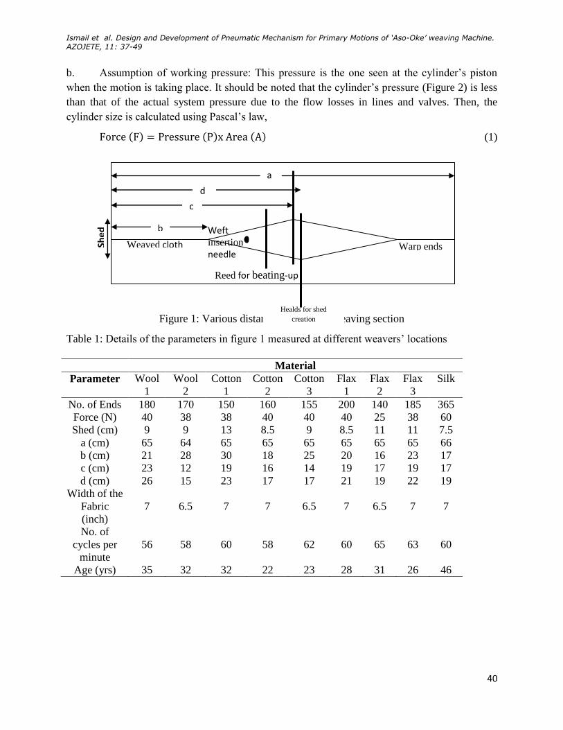
Figure 1 and Table 1 show the criteria considered in establishing the design concepts of the
pneumatic circuit.
2.1 Sizing of Pneumatic Cylinders for Shedding, Weft-Insertion and Beating-Up Operations
Determination of appropriate size of a cylinder (either pneumatic or hydraulic) for a particular
operation depends on two key factors, namely:
a. Total evaluation of the load: This load is not limited to the basic load to be moved by the
cylinder, but also includes any friction and force to accelerate the load, force needed to exhaust
the air from other end of the cylinder through the attached lines, control valve and any other
loads or force required to move the load as desired.
Ismail et al. Design and Development of Pneumatic Mechanism for Primary Motions of ‘Aso-Oke’ weaving Machine. AZOJETE, 11: 37-49
40
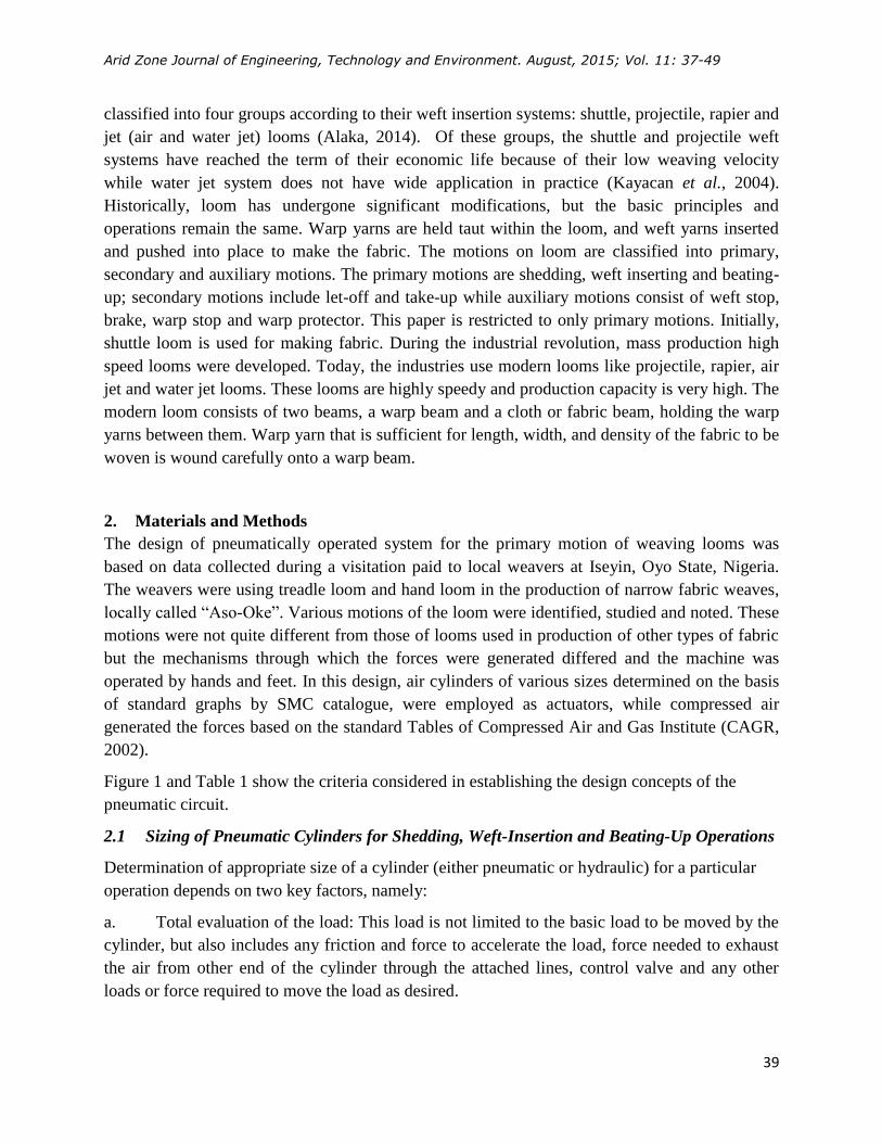
b. Assumption of working pressure: This pressure is the one seen at the cylinder’s piston
when the motion is taking place. It should be noted that the cylinder’s pressure (Figure 2) is less
than that of the actual system pressure due to the flow losses in lines and valves. Then, the
cylinder size is calculated using Pascal’s law,
(1)
Figure 1: Various distances around the weaving section
Table 1: Details of the parameters in figure 1 measured at different weavers’ locations
Material
Parameter Wool
1
Wool
2
Cotton
1
Cotton
2
Cotton
3
Flax
1
Flax
2
Flax
3
Silk
No. of Ends 180 170 150 160 155 200 140 185 365
Force (N) 40 38 38 40 40 40 25 38 60
Shed (cm) 9 9 13 8.5 9 8.5 11 11 7.5
a (cm) 65 64 65 65 65 65 65 65 66
b (cm) 21 28 30 18 25 20 16 23 17
c (cm) 23 12 19 16 14 19 17 19 17
d (cm) 26 15 23 17 17 21 19 22 19
Width of the
Fabric
(inch)
7
6.5
7
7
6.5
7
6.5
7
7
No. of
cycles per
minute
56
58
60
58
62
60
65
63
60
Age (yrs) 35 32 32 22 23 28 31 26 46
Shed
Warp ends Weaved cloth
Healds for shed
creation
Reed for beating-up
Weft insertion needle
b
a
c
d

Arid Zone Journal of Engineering, Technology and Environment. August, 2015; Vol. 11: 37-49
41
Figure 2: Double acting cylinder showing parameters of the cylinder
2.2 Evaluation of Total Load for each Operation
2.2.1 Shedding
The nature and type of forces involved in the shedding operation are diagrammatically
represented in Figure 3.
Figure 3: Analysis of shedding forces
(2)
(3)
Also,
(4)
θ
Th1
Th2
Ta
Tb
Fy

Ismail et. al. Design and Development of Pneumatic Mechanism for Primary Motions of ‘Aso-Oke’ weaving Machine. AZOJETE, 11: 37-49
42
= 147.21N
are the forces required to divide the warp yarns into two and create the shed, the
weight of the heald with its frame, , and yarn-to-yarn frictional force =
147.21x0.3 = 44.16N.
According to Vildan et al. (2013) appropriate inter-yarn frictional coefficient is 0.3.
Therefore, the force required to create the shed = (5)
= 147.21 + 4.51 + 44.16
= 195.883, approximated to 196 N.
With assumption of 5 bar working pressure,
From Pascal’s law:
(6)
Then, √
(7)
√
= 0.0223 m
= 22.3 mm
Two (2) Ø25 mm bore size cylinder, each with 60 mm stroke are to be used.
2.2.2 Weft Insertion
There are three cylinders to be selected for this operation: one to be used for the main insertion
operation, one acts as a hook to retain the newly inserted weft while the third one is meant for
reciprocating of the one serving as hook.
The force required by the weft insertion needle to unwind the weft yarn from three cones is
13.5N. With assumption of 5bar working pressure, using equation (7), we have:
√
= 0.00586 m
= 5.86 mm, approximated to 6 mm
Though, the remaining two cylinders do not require up to 13.5 N force, but the same size of
bores are to be selected since 6 mm is the smallest bore size commercially available.
2.2.3 Beating-up
Since the beating-up operation was carried out at the returning stroke of the piston, then,
(8)
Where: d = piston rod diameter.
Since the bore size, D, is the same, one can apply equation (7), so that,
Arid Zone Journal of Engineering, Technology and Environment. August, 2015; Vol. 11: 37-49
43
√
(9)
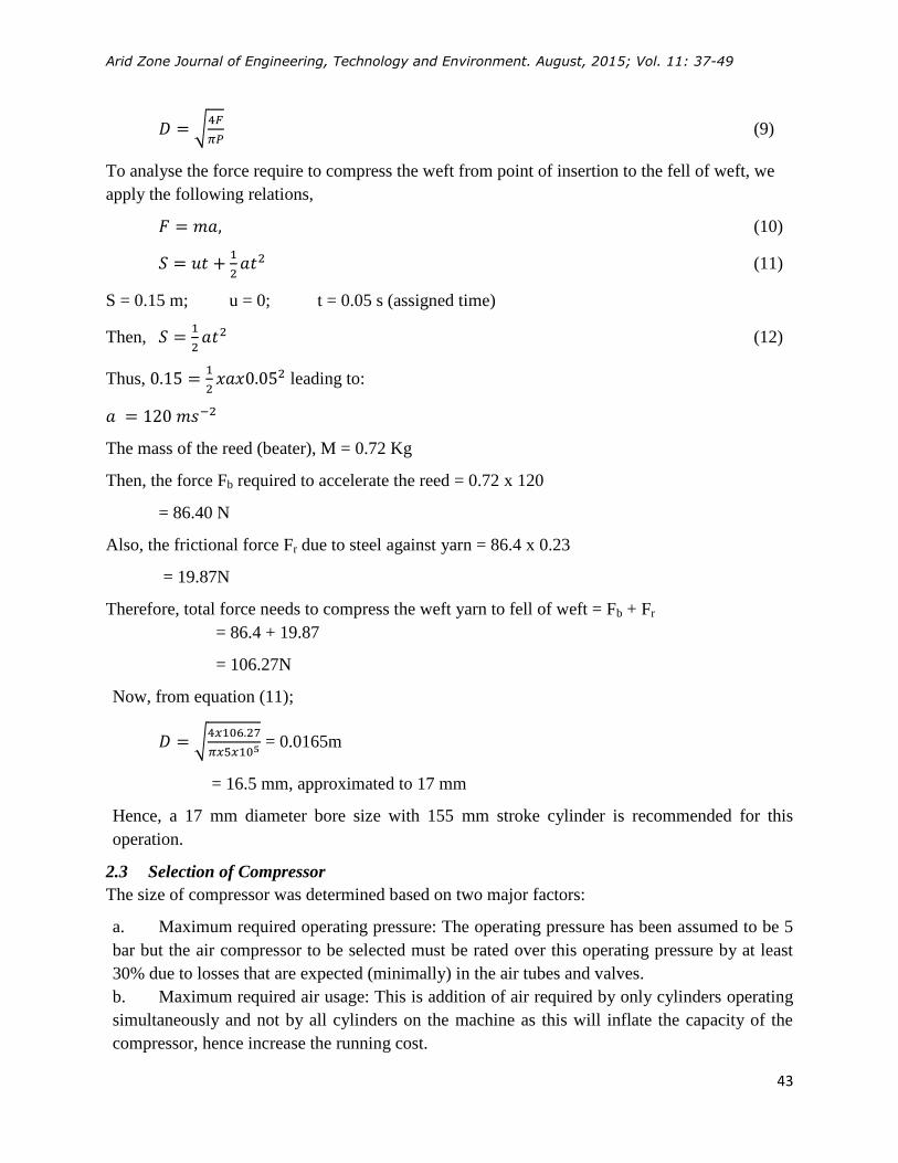
To analyse the force require to compress the weft from point of insertion to the fell of weft, we
apply the following relations,
(10)
(11)
S = 0.15 m; u = 0; t = 0.05 s (assigned time)
Then,
(12)
Thus,
leading to:
The mass of the reed (beater), M = 0.72 Kg
Then, the force Fb required to accelerate the reed = 0.72 x 120
= 86.40 N
Also, the frictional force Fr due to steel against yarn = 86.4 x 0.23
= 19.87N
Therefore, total force needs to compress the weft yarn to fell of weft = Fb + Fr
= 86.4 + 19.87
= 106.27N
Now, from equation (11);
√
= 0.0165m
= 16.5 mm, approximated to 17 mm
Hence, a 17 mm diameter bore size with 155 mm stroke cylinder is recommended for this
operation.
2.3 Selection of Compressor
The size of compressor was determined based on two major factors:
a. Maximum required operating pressure: The operating pressure has been assumed to be 5
bar but the air compressor to be selected must be rated over this operating pressure by at least
30% due to losses that are expected (minimally) in the air tubes and valves.
b. Maximum required air usage: This is addition of air required by only cylinders operating
simultaneously and not by all cylinders on the machine as this will inflate the capacity of the
compressor, hence increase the running cost.
Ismail et. al. Design and Development of Pneumatic Mechanism for Primary Motions of ‘Aso-Oke’ weaving Machine. AZOJETE, 11: 37-49
44
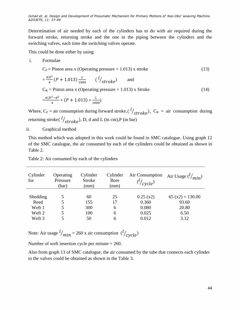
Determination of air needed by each of the cylinders has to do with air required during the
forward stroke, returning stroke and the one in the piping between the cylinders and the
switching valves, each time the switching valves operate.
This could be done either by using:
i. Formulae
CF = Piston area x (Operating pressure + 1.013) x stroke (13)
=
⁄ ) and
CR = Piston area x (Operating pressure + 1.013) x Stroke (14)
=
)
Where, CF = air consumption during forward stroke, ⁄ , CR = air consumption during
returning stroke ⁄ , D, d and L (in cm),P (in bar)
ii. Graphical method
This method which was adopted in this work could be found in SMC catalogue. Using graph 12
of the SMC catalogue, the air consumed by each of the cylinders could be obtained as shown in
Table 2.
Table 2: Air consumed by each of the cylinders
Note: Air usage ⁄ = 260 x air consumption ⁄
Number of weft insertion cycle per minute = 260.
Also from graph 13 of SMC catalogue, the air consumed by the tube that connects each cylinder
to the valves could be obtained as shown in the Table 3.
Cylinder
for
Operating
Pressure
(bar)
Cylinder
Stroke
(mm)
Cylinder
Bore
(mm)
Air Consumption
( ⁄ )
Air Usage ( ⁄ )
Shedding 5 60 25 0.25 (x2) 65 (x2) = 130.00
Reed 5 155 17 0.360 93.60
Weft 1 5 300 6 0.080 20.80
Weft 2 5 100 6 0.025 6.50
Weft 3 5 50 6 0.012 3.12

Arid Zone Journal of Engineering, Technology and Environment. August, 2015; Vol. 11: 37-49
45
Table 3: Air consumes by the tube that connects each cylinder to the valve
Hence, the total sum of air quantity to be consumed in one minute operation is addition of 161.72
litres and 4.97 litres, which is 166.69 litres. If 30% of this total is added for buffer in anticipation
of unknown and uncommon usage of the compressor, then the need can be approximated to
217 /litres cycle . Converting this value to Cubic Feet per Minute (cfm) of air delivery for the
purpose of compressor selection, we have 217 / 7.55litres cycle cfm .
On the compressor selector chart, Compressed Air and Gas Institute [13], under the column
“Continuous Operation” and cfm ranges 7.7 – 10.2 against one-stage, the compressor required is
a 3HP compressor.
2.4 Development of Pneumatic System
In order to get the proper workability of the pneumatic components, a model was created and ran
with FluidSim-P software of the Festo Pneumatic Simulation Software. In the first created
model, a control valve was connected to each of the air cylinders, that is, six control valves to six
air cylinders. It was later discovered (during testing of the model) that only one control valve
could be used to control two cylinders for shed operation, Figure 4. As a result of this discovery,
the number of control valves used in the development of the pneumatic circuit reduced by one,
hence reduced the cost of production. Then, the mechanical component(Figure 5) was
constructed, where each of the cylinders was positioned appropriately, the control valves were
also positioned and bolted onto the board, then, the connections were done with the air
compressor, control valves and the cylinders with air tubes of appropriate length as shown in
Figure 6.
Cylinder for Operating
Pressure (bar)
Piping Length
(m)
Pipe Bore
(mm) Air Consumption ( )
Shedding 5 0.6 8 0.28
Reed 5 0.8 8 0.40
Weft 1 5 0.7 8 0.33
Weft 2 5 0.7 8 0.15
Weft 3 5 0.7 8 0.15
Compressor 5 1.0 8 0.50

Ismail et. al. Design and Development of Pneumatic Mechanism for Primary Motions of ‘Aso-Oke’ weaving Machine. AZOJETE, 11: 37-49
46
Figure 4: Pneumatic Circuit for the three motions, using FluidSIM-P
Figure 5: Mechanical components for the three motions
Figure 6: Connection of Mechanical components with pneumatic and electrical
circuits for the three motions
2.5 Testing
After the development of the system, various tests were carried-out to ensure that the system
functions as desired.
Arid Zone Journal of Engineering, Technology and Environment. August, 2015; Vol. 11: 37-49
47
2.5.1 Manual Test
Each mechanism was connected separately to compressor (one after the other) and powered. It
was observed that each mechanism moved as expected, only that the number of weft insertion
per minute could not be determined yet.
2.5.2 Powered Test
Here, the mechanisms (that is, mechanical, pneumatic and electrical mechanisms) were
connected and the test was carried out.
3. Results and Discussion
The weft insertion needle of this mechanism is made such that the machine can weave 300 mm
width Aso Oke against the existing 175 mm.
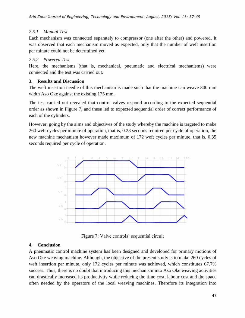
The test carried out revealed that control valves respond according to the expected sequential
order as shown in Figure 7, and these led to expected sequential order of correct performance of
each of the cylinders.
However, going by the aims and objectives of the study whereby the machine is targeted to make
260 weft cycles per minute of operation, that is, 0.23 seconds required per cycle of operation, the
new machine mechanism however made maximum of 172 weft cycles per minute, that is, 0.35
seconds required per cycle of operation.
Figure 7: Valve controls’ sequential circuit
4. Conclusion
A pneumatic control machine system has been designed and developed for primary motions of
Aso Oke weaving machine. Although, the objective of the present study is to make 260 cycles of
weft insertion per minute, only 172 cycles per minute was achieved, which constitutes 67.7%
success. Thus, there is no doubt that introducing this mechanism into Aso Oke weaving activities
can drastically increased its productivity while reducing the time cost, labour cost and the space
often needed by the operators of the local weaving machines. Therefore its integration into
Ismail et. al. Design and Development of Pneumatic Mechanism for Primary Motions of ‘Aso-Oke’ weaving Machine. AZOJETE, 11: 37-49
48
activities of Aso-Oke weaving is hereby recommended to alleviate challenges usually faced by
the Aso-Oke weavers.
Acknowledgement
The authors gratefully acknowledge the support grant of STEP-B World Bank project. In
addition the technical and moral supports from members of staff, Technical Support Unit of the
Faculty of Technology, University of Ibadan during the construction of the machine components
and its assembly are well acknowledged.
References
Ademuleya, BA. 2014. Ondo in the History of Aso-Òkè Weaving in Southwestern Nigeria.
Mediterranean Journal of Social Sciences, 5(20): 2127 – 2132.
Ajila, KO. 2016. An Appraisal of Traditional Woven Fabric Production in Southwestern Nigeria.
European Journal of Sustainable Development, 5(1): 63-76.
Akinwonmi, AS. 2011. Design and Construction of a Mechanized Loom. Research Journal of
Applied Science, Engineering and Technology, 3(3): 159-171.
Alaka, A. 2014. Design and Construction of a Shuttle less Aso-Oke Weaving Machine. M.Sc.
Thesis, Department of Mechanical Engineering, Faculty of Technology, University of Ibadan,
Ibadan, Nigeria.
Alssarraf, AAY., Ahmed MI. and Alkhedir MA. 2007. Design and development of a pneumatic
circuit bench for education purposes. International Conference on Engineering Education,
Coimbra, Portugal. pp 3 – 7.
Aretha, OA. 2007. Functions of Hand Woven Textiles among Yoruba Women in Southwestern
Nigeria. Nordic Journal of African Studies, 16(1): 101–115.
Chinedu, CC. and JovitaOgu, C. 2013. Akwete Weaving in the Secondary Schools Curriculum in
Imo State: A Proposal. The Crab: Journal of Theatre and Media Arts, 8:1-11.
Compressed Air and Gas Institute 2002. Air Compressor Selection and Application, 1/4HP
through 30HP, pp16-17. http://www.cagi.org/pdfs/CAGIAirCompressorHP.pdf
Kayacan, MC., Dayik, M., Colakand, O. and Kodaloglu, M. 2004. Velocity control of weft
insertion on air jet looms by fussing logic. Fibres and Textiles in Eastern Europe, 12(3): 29 – 33.
Lai, JY., Menq, CH. and Singh, R. 1990. Accurate position Control of a Pneumatic Actuator.
ASME, Journal of Dynamic Systems, Measurements and Control, 112: 734-739.

Arid Zone Journal of Engineering, Technology and Environment. August, 2015; Vol. 11: 37-49
49
Liu S. and Bobrow JE. 1988. An Analysis of a Pneumatic Servo System and its Applications to a
Computer-Controlled Robot. ASME, Journal of Dynamic Systems, Measurements and Control,
110: 228-235.
Olutayo, AO., Olayinka, A. and Fadina, OA. 2011. Aso-oke (Hand Woven Textiles) of
Southwestern Nigeria: A Compact Examination of a Resilient Artifact. American Journal of
Sociological Research, 1(1): 9-17.
Olutayo, AO. and Akanle, O. 2009. Aso-oke (Yoruba’s Hand Woven Textiles) usage among the
youths in Lagos, Southwestern Nigeria. International Journal of Sociology and Anthropology,
1(3): 62-69.
SMC Catalogue. Air Cylinder Model Selection Procedures, pp. 18-36,
http://www.smclt.lt/failai/cilind_s_EU.pdf
Vildan, S., Eren, Ö. and Ayşe, O. 2013. Roughness and Frictional Properties of Cotton and
Polyester Woven Fabrics. Indian Journal of Fibre and Textile Research, 38: 349-356.
Related Documents