3M ™ Self-Regulating Heat Tracing Cables for Commercial Buildings

Welcome message from author
This document is posted to help you gain knowledge. Please leave a comment to let me know what you think about it! Share it to your friends and learn new things together.
Transcript

Division des produits électriquesCompagnie 3M Canada C.P. 5757London, ON N6A 4T1
1408-01605-F
© 3M, 2014. Tous droits réservés. Imprimé au Canada. 3M TTS, HSX et KSR sont des marques de commerce de 3M, utilisées sous licence au Canada.
3M™ Self-Regulating Heat Tracing Cablesfor Commercial Buildings
PLEASE NOTE: The diagrams and instructions outlined in this guide are for illustration purposes only. They are not necessarily to scale and do not necessarily represent exact real-world heat tracing systems. In addition, they are not meant or implied to be a replacement for a licensed professional. Any use of 3M Heat Tracing Cables must be in accordance with all local regulations and/or building codes. Please consult your local authority.

Contents
1
3M™ Self-Regulating Heating CablesConstruction & Function:Introduction.......... .................................................................................................... 2
Properties ................................................................................................................. 2
Advantages ............................................................................................................... 2
Construction ............................................................................................................. 3
3M™ Self-Regulating Heating Cables Ordering Information & Materials Guide:Pipe Freeze Protection Ordering Information (TTS Cable).......... ................................. 4
Pipe Freeze Protection Materials Guide (TTS Cable) ................................................... 6
Roof & Gutter Snow & Ice Melting Ordering Information (TTS Cable) ........................ 15
Roof & Gutter Snow & Ice Melting Materials Guide (TTS Cable) ............................... 17
Surface Snow & Ice Melting Ordering Information (KSR Cable) ................................ 25
Surface Snow & Ice Melting Materials Guide (KSR Cable) ........................................ 27
Hot Water Temperature Maintenance Ordering Information (HSX Cable) .................. 36
Data Sheets:TTS Pipe Freeze Protection DATA Sheet .................................................................. 37
TTS Roof & Gutter Snow & Ice Melting DATA Sheet ................................................ 40
KSR Surface Snow & Ice Melting DATA Sheet .......................................................... 41
HSX Hot Water Temperature Maintenance DATA Sheet ............................................ 42
Accessories ................................................................................................... 43

Introduction:3M Canada and Thermon Manufacturing Company have entered into a strategic alliance to market the commercial line of heat tracing products manufactured by Thermon. The alliance agreement provides 3M Canada exclusive rights within Canada to sell and market three distinct products: TTS™, KSR™, and HSX™ heat tracing cables and accessories.
Properties:These heat tracing cables consist of a conductive-polymer heating matrix extruded between two parallel copper bus conductors. Heat is generated in the conductive polymer matrix when energized. The bus conductors provide uniform voltage across the heating matrix by providing current down the entire length of the cable. The conductive polymer matrix is irradiated with an electron beam to provide cross-linking and “lock in” performance properties.
As the temperature increases, the electrical paths in the carbon-polymer heating matrix become longer and the resistance of the heating element increases. This causes the heat output of the cable to decrease. As the temperature of the heating matrix increases, the resistance of the heating matrix increases. This is a self-regulating effect.
Self-regulating heat tracing cables can adjust their output to the surrounding tem-perature down the cable length. This adaptability to individual thermal conditions provides more heat where needed and can also reduce energy consumption as the ambient temperature increases, reducing heating costs.
Advantages:• Self-regulating heat output at any point • Cut-to-length at any point down the cable • No overheating • Can overlap heating cable • Economical, simple installation • Safe assembly due to simple handling • Low investment • Reliable, long term performance
2 Construction & Function
3M™ Self-Regulating Heating Cables
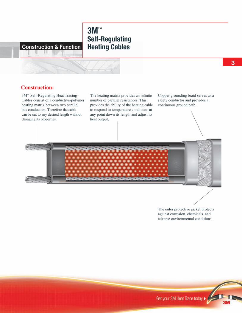
3M™ Self-Regulating Heat Tracing Cables consist of a conductive-polymer heating matrix between two parallel bus conductors. Therefore the cable can be cut to any desired length without changing its properties.
The heating matrix provides an infinite number of parallel resistances. This provides the ability of the heating cable to respond to temperature conditions at any point down its length and adjust its heat output.
Copper grounding braid serves as a safety conductor and provides a continuous ground path.
The outer protective jacket protects against corrosion, chemicals, and adverse environmental conditions.
3M™ Self-Regulating Heating Cables
3
Construction:
Construction & Function

TTS™
Self-Regulating Heating Cablefor Pipe Freeze Protection
Description:Cut-to-length TTS Self-Regulating heating cables are designed to provide freeze protection to metallic and non-metallic piping. Whether the application is a small project or a complex network, designing an electric heat trace system is easy with TTS heating cable.
Please refer to the TTS materials guide for Pipe Freeze Protection on page 8 of this catalogue for full details.
TTS heating cables are are approved for use in ordinary (non-classified) and hazardous (classified) areas.
Areas of Application:• Freeze protection or low temperature maintenance • Metallic or non-metallic piping tanks and equipment • Sewage pipes, intake and drain lines (external tracing only) • Water meters and outside pipes/taps • Water pipes in unheated areas • Sprinkler systems • Refrigeration * For pipe freeze protection add thermal insulation for a complete installation
Ratings:Available watt densities......................................................16, 26, 33 w/m @ 10° C (5, 8, 10 w/ft @50° F) Supply Voltages...................................................................110-120 or 208-240 Vac Max. Maintenance temperature..........................................................65° C (150° F) Max. Continuous exposure temperature Power off............................................................................. 85° C (185° F) Minimum installation temperature.....................................................-51° C (-60° F) Minimum bend radius........................................................................ 32 mm (1.25") T-rating..........................................................................................T6 85° C (185° F)
4
Certifications / Approvals:Canadian Standards Association Ordinary (Non-Classified) Locationss Hazardous (Classified) Locations Class I, Division 2, Groups A, B, C and D Class II, Division 2, Groups F and G Meets or exceeds - IEEE 515, 515.1 - UL 1588CSA 130.3
Ordering Information

TTS™
Self-Regulating Heating Cablefor Pipe Freeze Protection
5
T
9
2
3
4
5
6
7
8
1
Ref # Part Number Description
1 TTS-5-1-OJ 5 W/FT @ 120V 1 TTS-8-1-OJ 8 W/FT @ 120V 1 TTS-10-1-OJ 10 W/FT @ 120V 1 TTS-5-2-OJ 5 W/FT @ 240V 1 TTS-8-2-OJ 8 W/FT @ 240V 1 TTS-10-2-OJ 10 W/FT @ 240V
Cable
Termination Kits 2 18-SXG-KIT1 Power Connection Gland Kit w/o Junction Box
2 ECA-1-SR-SP Metallic Power Connection Kit with Junction Box 4 ECT-2-SR Metallic T-Splice Kit with Junction Box 2 PCA-1-SR Non-metallic Power Connection Kit with Junction Box 4 PCS-1-SR Non-metallic T-Splice Kit with Splice Cover 1
8 HS-PBSK Inline Heat Shrink Splice Kit (Under Insulation) 4 HS-TBSK T-Splice Heat Shrink Kit (Under Insulation) 5 ET-6C End Termination Kit (Ordinary & Div 2 Approved)
Installation Accessories 6 BTape Binding / Attachment Tape (1/2" X 60 yds) 7 CL Caution Labels (25 Per Pack) 9 AL TAPE 3M™ Aluminum Tape (2" X 180') for
non-metallic pipe
Controls 3 R1-050-DP Indoor Thermostat 3 R3C-0120-DP Weatherproof Indoor / Outdoor Thermostat
Ordering Information
Basic Components:A pipe freeze protection system that uses TTS heating cable will typically include heating cable and components shown in the illustration and TTS ordering information table below.
1 Junction box appropriate for the application to be supplied by the installer.

TTS™
Self-Regulating Heating Cablefor Pipe Freeze Protection6 Materials Guide
ContentsIntroduction ..................................................................................................7
Creating a Materials List
Step 1: Establish Parameters ..................................................................8 Step 2: Select the Proper TTS Heating Cable ........................................9 Step 3: Determine TTS Circuit Lengths ..............................................11 Step 4: Choose TTS Installation Accessories ......................................12
Tips .............................................................................................................13
Thermostatic Control .................................................................................14

TTS™
Self-Regulating Heating Cablefor Pipe Freeze Protection
Introduction:While an insulated pipe can withstand cold temperatures longer than an uninsulated pipe, the contents of the pipe will cool to the temperature of the surrounding environment. When the ambient temperature is below freezing, the results can be both costly and inconvenient. TTS self-regulating heating cable is designed to provide freeze protection of metallic and non-metallic pipes by replacing the heat lost through the thermal insulation into the air.
Whether the application is a small project or a complex network of piping and equipment, designing an electric heat-traced freeze protection system is easy with TTS. The information contained in this materials guide will take the reader through a step-by-step procedure to make proper heating cable selections based on:
• Minimum ambient temperature
• Heating cable start-up temperature
• Pipe size
• Thermal insulation type and thickness
• Available power supply
7
Materials Guide
Safety Comes First:The safety and performance of electric heat tracing depends on how the cable was selected, installed and eventually maintained. Improper handling, installation or maintenance of the cable could result in electrical shock, fire or cable failure. The information, instructions, testing procedures and warnings addressed in this guide are important. To minimize these risks, read this guide prior to starting any heating cable or component installation and follow the instructions carefully.
The Canadian Electrical Code requires that all heat tracing applications utilize ground-fault protection. This protection requirement can be achieved through ground-fault branch circuit breakers supplying power to the heating cable.
If higher maintain temperatures are required, contact 3M for additional information.

Creating a Materials List: The generally accepted maintenance temperature for freeze protection is 5° C (40° F.) This design guide is based on maintaining 5° C (40° F) temperature and provides a safety factor to protect the piping and the contents from freezing.
To become familiar with the requirements of a properly designed electric heat tracing freeze protection system, use the five design steps detailed here and on the following pages.
Step 1: Establish ParametersCollect information relative to the following design parameters:
Application Information:• Pipe sizes or tubing diameters • Pipe lengths • Pipe material (metallic or nonmetallic) • Type and number of valves, pumps or other equipment • Type and number of pipe supports
Expected Minimum Ambient Temperature: Generally, this number is obtained from weather data compiled for an area and is based on recorded historical data. There are times, however, when the minimum ambient will be a number
8 Materials Guide
TTS™
Self-Regulating Heating Cablefor Pipe Freeze Protection
other than the minimum outside air temperature. Piping located inside of unheated buildings or in unconditioned attics may be subject to freezing but may have different minimum ambients
Minimum Start-Up Temperature: This temperature differs from the minimum expected ambient in that the heating cable will typically be energized at a higher ambient temperature. This temperature will have an effect on the maximum circuit length and circuit breaker sizing for a given application.
Insulation Material and Thickness: The selection charts in this guide are based on fiberglass insulation. These charts may also be used with Polyisocyanurate or Mineral Wool insulations of the same thickness. If insulation materials other than these are used, contact your 3M representative for a selection chart supplement that corresponds with the insulation material.
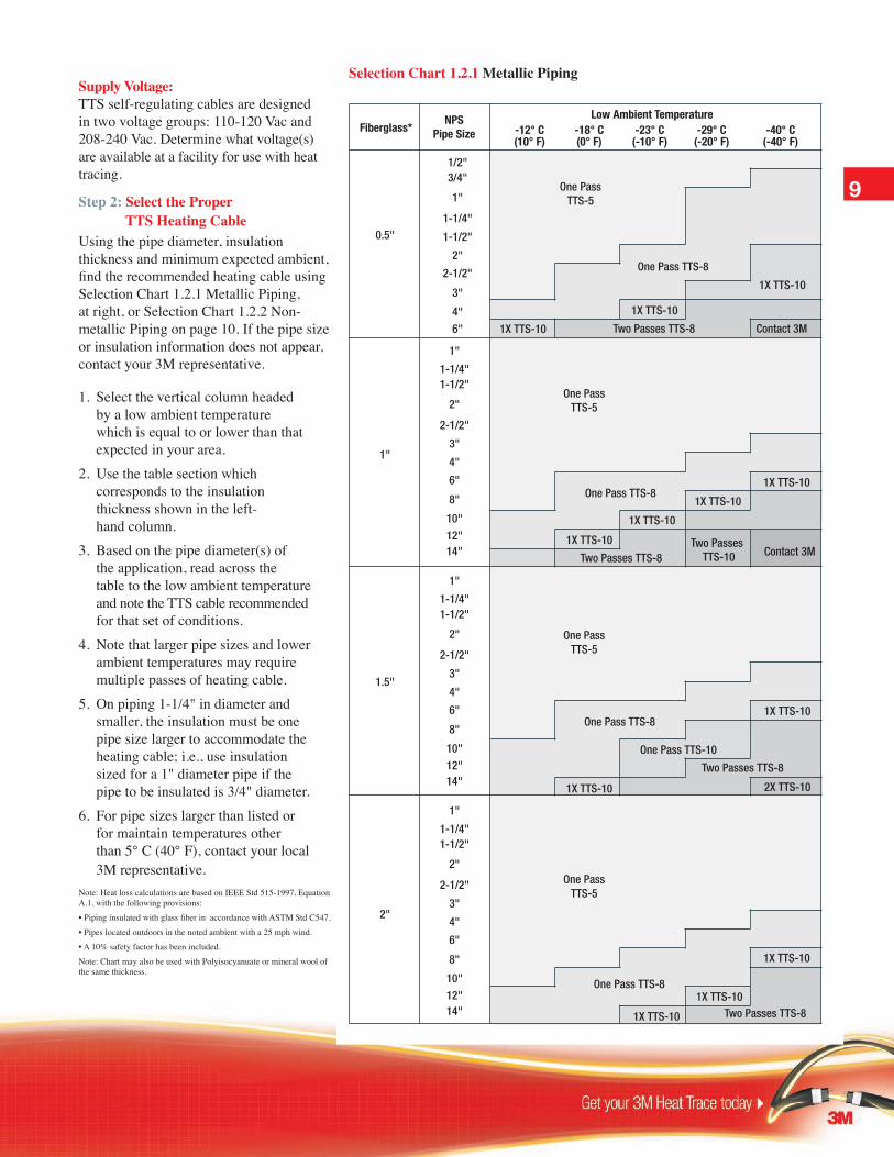
Supply Voltage: TTS self-regulating cables are designed in two voltage groups: 110-120 Vac and 208-240 Vac. Determine what voltage(s) are available at a facility for use with heat tracing.
Step 2: Select the Proper TTS Heating CableUsing the pipe diameter, insulation thickness and minimum expected ambient, find the recommended heating cable using Selection Chart 1.2.1 Metallic Piping, at right, or Selection Chart 1.2.2 Non-metallic Piping on page 10. If the pipe size or insulation information does not appear, contact your 3M representative. 1. Select the vertical column headed by a low ambient temperature which is equal to or lower than that expected in your area.2. Use the table section which corresponds to the insulation thickness shown in the left- hand column.3. Based on the pipe diameter(s) of the application, read across the table to the low ambient temperature and note the TTS cable recommended for that set of conditions.4. Note that larger pipe sizes and lower ambient temperatures may require multiple passes of heating cable.5. On piping 1-1/4" in diameter and smaller, the insulation must be one pipe size larger to accommodate the heating cable; i.e., use insulation sized for a 1" diameter pipe if the pipe to be insulated is 3/4" diameter.6. For pipe sizes larger than listed or for maintain temperatures other than 5° C (40° F), contact your local 3M representative.Note: Heat loss calculations are based on IEEE Std 515-1997, Equation A.1, with the following provisions:
• Piping insulated with glass fiber in accordance with ASTM Std C547.
• Pipes located outdoors in the noted ambient with a 25 mph wind.
• A 10% safety factor has been included.
Note: Chart may also be used with Polyisocyanuate or mineral wool of the same thickness.
15
Selection Chart 1.2.1 Metallic Piping
9
NPSPipe Size
Low Ambient TemperatureFiberglass*
0.5"
1/2"
One PassTTS-5
One Pass 8-TTS
1X TTS-10
1X TTS-10
One PassTTS-5
One PassTTS-5
One PassTTS-5
1X TTS-10
1X TTS-10
1X TTS-10
1X TTS-10
1X TTS-10
One Pass TTS-10
2X TTS-10
1X TTS-10
1X TTS-10
1X TTS-10
1X TTS-10
1X TTS-10
3/4"
1"
1-1/4"
1-1/2"
2"
2-1/2"
3"
4"
6"
1-1/4"1-1/2"
2"
2-1/2"
3"
4"
6"
8"
10"
12"14"
1"
1.5"
2"
-12° C(10° F)
-18° C(0° F)
-23° C(-10° F)
-29° C(-20° F)
-40° C(-40° F)
1"
1-1/4"1-1/2"
2"
2-1/2"
3"
4"
6"
8"
10"
12"14"
1"
1-1/4"1-1/2"
2"
2-1/2"
3"
4"
6"
8"
10"
12"14"
1"
One Pass TTS-8
One Pass TTS-8
One Pass TTS-8
One Pass TTS-8
Two Passes TTS-8
Two Passes TTS-8
Two Passes TTS-8
Two Passes TTS-10 Contact 3M
Two Passes TTS-8 Contact 3M
NPSPipe Size
Low Ambient TemperatureFiberglass* -12° C
(10° F)-18° C(0° F)
-23° C(-10° F)
-29° C(-20° F)
-40° C(-40° F)
1X TTS-10
1X TTS-10
1X TTS-10
One Pass TTS-5
One Pass TTS-8
Two Passes TTS-8
1X TTS-10
1X TTS-10
1X TTS-10
1X TTS-10
One Pass TTS-5
One Pass TTS-5
Two Passes TTS-8
One Pass TTS-5
One Pass TTS-8
One Pass TTS-8
1X TTS-10
1X TTS-10
1X TTS-10 2 X TTS-8
1X TTS-10
One Pass TTS-8One PassTTS-10
Two Passes TTS-8Two Passes
TTS-10
0.5"
1/2"3/4"
1"
1-1/4"
1-1/2"
2"
2-1/2"
3"
4"
6"
1-1/4"1-1/2"
2"
2-1/2"
3"
4"
6"
8"
10"
12"14"
1"
1.5"
2"
1"
1-1/4"1-1/2"
2"
2-1/2"
3"
4"
6"
8"
10"
12"14"
1"
1-1/4"1-1/2"
2"
2-1/2"
3"
4"
6"
8"
10"
12"14"
1"
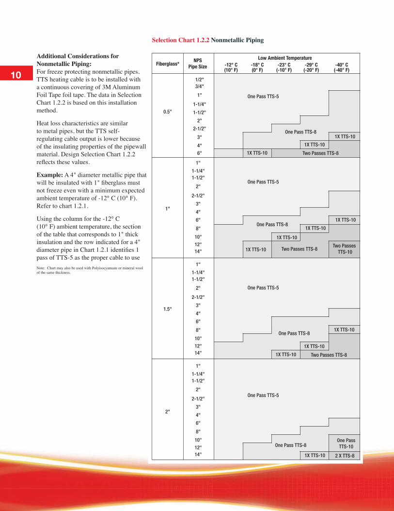
Selection Chart 1.2.2 Nonmetallic Piping
Additional Considerations for Nonmetallic Piping: For freeze protecting nonmetallic pipes, TTS heating cable is to be installed with a continuous covering of 3M Aluminum Foil Tape foil tape. The data in Selection Chart 1.2.2 is based on this installation method.
Heat loss characteristics are similar to metal pipes, but the TTS self- regulating cable output is lower because of the insulating properties of the pipewall material. Design Selection Chart 1.2.2 reflects these values.
Example: A 4" diameter metallic pipe that will be insulated with 1" fiberglass must not freeze even with a minimum expected ambient temperature of -12° C (10° F). Refer to chart 1.2.1.
Using the column for the -12° C (10° F) ambient temperature, the section of the table that corresponds to 1" thick insulation and the row indicated for a 4" diameter pipe in Chart 1.2.1 identifies 1 pass of TTS-5 as the proper cable to useNote: Chart may also be used with Polyisocyanuate or mineral wool of the same thickness.
10

11
Materials Guide
TTS™
Self-Regulating Heating Cablefor Pipe Freeze Protection
Table 1.3.1 Valve and Pump AllowancesValve Alowance Pump Allowance
Pipe Size Screwed Flanged Welded Screwed Flanged1/2" 6" 1' 0 1' 2'3/4" 9" 1' 6" 0 1' 6" 3'1" 1' 2' 1' 2' 4'
1-1/4" 1' 6" 2' 1' 3' 4' 6"1-1/2" 1' 6" 2' 6" 1' 6" 3' 5'
2" 2' 2' 6" 2' 4' 5' 6"3" 2' 6" 3' 6" 2' 6" 5' 7'4" 4' 5' 3' 8' 10'6" 7' 8' 3' 6" 14' 16'8" 9' 6" 11' 4' 19' 22'10" 12' 6" 14' 4' 25' 28'12" 15' 16' 6" 5' 30' 33'14" 18' 19' 6" 5' 6" 36' 39'
Step 3: Determine TTS Cable Circuit Lengths
Heat tracing circuit lengths are based on several conditions which must be simultaneously taken into account and include:• Length of piping (including extra allowances) • Operating voltage • Available branch circuit breaker sizes • Expected start-up temperature • Maximum allowable circuit lengthsEvery heat tracing circuit will require some additional heating cable to make the various splices and terminations. Additional cable will also be needed to provide extra heat at valves, pumps, miscellaneous equipment and pipe
supports. Use the following guidelines to determine the amount of extra cable required: • Valves and pumps: Use allowances from Table 1.3.1.• Miscellaneous equipment and pipe supports: use allowances from Table 1.3.1ATo determine circuit lengths, a voltage selection must be made from the available voltages gathered as part of Step 1.• TTS cable intended for use on
110-120 Vac will have a catalog number followed by a 1; i.e., TTS-X-1.
• TTS cable intended for use on 208-240 Vac will have a catalog number followed by a 2; i.e., TTS-X-2.
In Step 2 the proper TTS cable (5, 8 or 10) was selected from Selection Chart 1.2.1 or 1.2.2. Using voltage and cable selections plus Table 1.3.2 or 1.3.3 the maximum heating cable lengths and branch circuit breaker requirements can be determined.• If a branch circuit breaker of a known amperage will be used, match this rating with the cable selection and the temperature at which the cable will be energized.• If no circuit breaker sizing has been established, find the maximum circuit length that meets or exceeds the length of the appropriate TTS cable at the start-up temperature of the cable and determine what amperage branch circuit breaker will be required.Remember the start-up temperature does not necessarily match the expected low ambient.
Table 1.3.1 A Other AllowancesDescription Allowance
Power Connections 1 foot of TTS cable for each heating circuit
Splices 2 feet of TTS cable for each splice kit / 3 feet of TTS cable for each TSplice kit
Insulated Pipe Supports Require no additional heating cable
Uninsulated Pipe Supports
Allow 2 times the length of the pipe support plus and additional foot of heating cable for each support
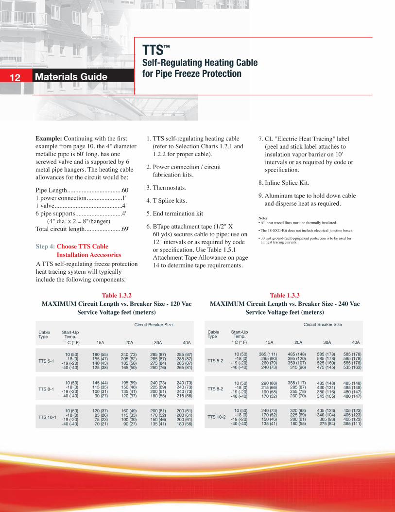
Table 1.3.3 MAXIMUM Circuit Length vs. Breaker Size - 240 Vac
Service Voltage feet (meters)
Example: Continuing with the first example from page 10, the 4" diameter metallic pipe is 60' long, has one screwed valve and is supported by 6 metal pipe hangers. The heating cable allowances for the circuit would be:
Pipe Length..................................60' 1 power connection......................1' 1 valve..........................................4' 6 pipe supports.............................4' (4" dia. x 2 = 8"/hanger) Total circuit length.......................69'
Table 1.3.2 MAXIMUM Circuit Length vs. Breaker Size - 120 Vac
Service Voltage feet (meters)
TTS™
Self-Regulating Heating Cablefor Pipe Freeze Protection12 Materials Guide
TTS 5-1
TTS 8-1
TTS 10-1
Circuit Breaker SizeCableType
Start-Up Temp.
30A20A15A° C (° F) 40A
10 (50)-18 (0)
-19 (-20)-40 (-40)
180 (55)155 (47)140 (43)125 (38)
240 (73)205 (62)185 (56)165 (50)
285 (87)285 (87)275 (84)250 (76)
285 (87)285 (87)285 (87)265 (81)
10 (50)-18 (0)
-19 (-20)-40 (-40)
145 (44)115 (35)100 (31)
90 (27)
195 (59)150 (46)135 (41)120 (37)
240 (73)225 (69)200 (61)180 (55)
240 (73)240 (73)240 (73)215 (66)
10 (50)-18 (0)
-19 (-20)-40 (-40)
120 (37)85 (26)75 (23)70 (21)
160 (49)115 (35)100 (30)
90 (27)
200 (61)170 (52)150 (46)135 (41)
200 (61)200 (61)200 (61)180 (56)
TTS 5-2
TTS 8-2
TTS 10-2
Circuit Breaker SizeCableType
Start-Up Temp.
30A20A15A° C (° F) 40A
10 (50)-18 (0)
-19 (-20)-40 (-40)
365 (111)295 (90)260 (79)240 (73)
485 (148)395 (120)350 (107)
315 (96)
385 (117)285 (87)255 (78)230 (70)
585 (178)585 (178)525 (160)475 (145)
585 (178)585 (178)585 (178)535 (163)
10 (50)-18 (0)
-19 (-20)-40 (-40)
290 (88)215 (66)190 (58)170 (52)
485 (148)430 (131)380 (116)345 (105)
485 (148)485 (148)480 (147)480 (147)
10 (50)-18 (0)
-19 (-20)-40 (-40)
240 (73)170 (52)150 (46)135 (41)
320 (98)225 (69)200 (61)180 (55)
405 (123)340 (104)
305 (93)275 (84)
405 (123)405 (123)405 (123)365 (111)
Step 4: Choose TTS Cable Installation Accessories
A TTS self-regulating freeze protection heat tracing system will typically include the following components:
1. TTS self-regulating heating cable (refer to Selection Charts 1.2.1 and 1.2.2 for proper cable).
2. Power connection / circuit fabrication kits.
3. Thermostats.
4. T Splice kits.
5. End termination kit
6. BTape attachment tape (1/2" X 60 yds) secures cable to pipe; use on 12" intervals or as required by code or specification. Use Table 1.5.1 Attachment Tape Allowance on page 14 to determine tape requirements.
7. CL "Electric Heat Tracing" label (peel and stick label attaches to insulation vapor barrier on 10' intervals or as required by code or specification.
8. Inline Splice Kit.
9. Aluminum tape to hold down cable and disperse heat as required.
Notes: • All heat-traced lines must be thermally insulated.
• The 18-SXG-Kit does not include electrical junction boxes.
• 30 mA ground-fault equipment protection is to be used for all heat tracing circuits.
TTS™
Self-Regulating Heating Cablefor Pipe Freeze Protection
13
Materials Guide
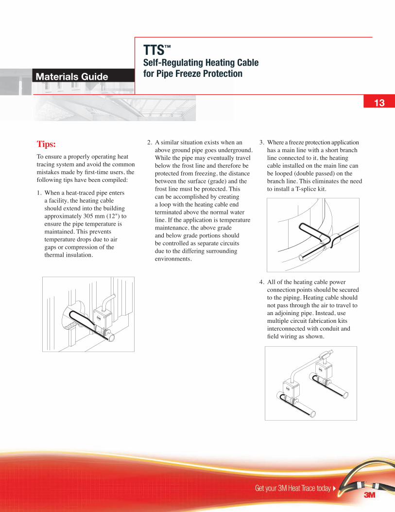
Tips:To ensure a properly operating heat tracing system and avoid the common mistakes made by first-time users, the following tips have been compiled:
1. When a heat-traced pipe enters a facility, the heating cable should extend into the building approximately 305 mm (12") to ensure the pipe temperature is maintained. This prevents temperature drops due to air gaps or compression of the thermal insulation.
2. A similar situation exists when an above ground pipe goes underground. While the pipe may eventually travel below the frost line and therefore be protected from freezing, the distance between the surface (grade) and the frost line must be protected. This can be accomplished by creating a loop with the heating cable end terminated above the normal water line. If the application is temperature maintenance, the above grade and below grade portions should be controlled as separate circuits due to the differing surrounding environments.
3. Where a freeze protection application has a main line with a short branch line connected to it, the heating cable installed on the main line can be looped (double passed) on the branch line. This eliminates the need to install a T-splice kit.
4. All of the heating cable power connection points should be secured to the piping. Heating cable should not pass through the air to travel to an adjoining pipe. Instead, use multiple circuit fabrication kits interconnected with conduit and field wiring as shown.
TTS™
Self-Regulating Heating Cablefor Pipe Freeze Protection14
Table 1.5.1 Attachment Tape Allowance (BTape)
Materials Guide
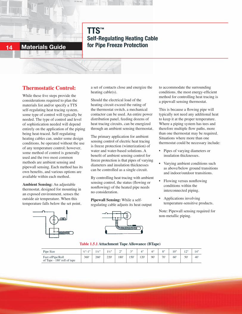
Thermostatic Control:While these five steps provide the considerations required to plan the materials list and/or specify a TTS self-regulating heat tracing system, some type of control will typically be needed. The type of control and level of sophistication needed will depend entirely on the application of the piping being heat-traced. Self-regulating heating cables can, under some design conditions, be operated without the use of any temperature control; however, some method of control is generally used and the two most common methods are ambient sensing and pipewall sensing. Each method has its own benefits, and various options are available within each method.
Ambient Sensing: An adjustable thermostat, designed for mounting in an exposed environment, senses the outside air temperature. When this temperature falls below the set point,
a set of contacts close and energize the heating cable(s).
Should the electrical load of the heating circuit exceed the rating of the thermostat switch, a mechanical contactor can be used. An entire power distribution panel, feeding dozens of heat tracing circuits, can be energized through an ambient sensing thermostat.
The primary application for ambient sensing control of electric heat tracing is freeze protection (winterization) of water and water-based solutions. A benefit of ambient sensing control for freeze protection is that pipes of varying diameters and insulation thicknesses can be controlled as a single circuit.
By controlling heat tracing with ambient sensing control, the status (flowing or nonflowing) of the heated pipe needs no consideration.
Pipewall Sensing: While a self-regulating cable adjusts its heat output
to accommodate the surrounding conditions, the most energy-efficient method for controlling heat tracing is a pipewall sensing thermostat.
This is because a flowing pipe will typically not need any additional heat to keep it at the proper temperature. Where a piping system has tees and therefore multiple flow paths, more than one thermostat may be required. Situations where more than one thermostat could be necessary include:
• Pipes of varying diameters or insulation thicknesses.
• Varying ambient conditions such as above/below ground transitions and indoor/outdoor transitions.
• Flowing versus nonflowing conditions within the interconnected piping.
• Applications involving temperature-sensitive products.
Note: Pipewall sensing required for non-metallic piping.
Pipe Size ½"-1" 1¼" 1½" 2" 3" 4" 6" 8" 10" 12" 14"
Feet ofPipe/Roll of Tape - 180' roll of tape
360' 260' 220' 180' 150' 120' 90' 70' 60' 50' 40'
TTS™
Self-Regulating Heating Cablefor Roof & Gutter Snow & Ice Melting
15
Ordering Information
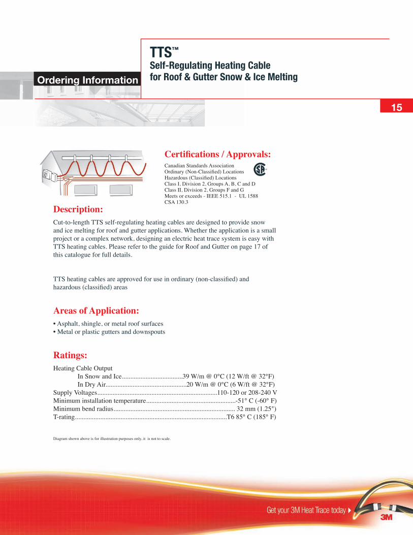
Description:Cut-to-length TTS self-regulating heating cables are designed to provide snow and ice melting for roof and gutter applications. Whether the application is a small project or a complex network, designing an electric heat trace system is easy with TTS heating cables. Please refer to the guide for Roof and Gutter on page 17 of this catalogue for full details.
TTS heating cables are approved for use in ordinary (non-classified) and hazardous (classified) areas
Areas of Application:• Asphalt, shingle, or metal roof surfaces • Metal or plastic gutters and downspouts
Ratings:Heating Cable Output In Snow and Ice....................................39 W/m @ 0°C (12 W/ft @ 32°F) In Dry Air................................................20 W/m @ 0°C (6 W/ft @ 32°F) Supply Voltages.......................................................................110-120 or 208-240 V Minimum installation temperature.....................................................-51° C (-60° F) Minimum bend radius........................................................................ 32 mm (1.25") T-rating..........................................................................................T6 85° C (185° F)
Diagram shown above is for illustration purposes only, it is not to scale.
Certifications / Approvals:Canadian Standards Association Ordinary (Non-Classified) Locations Hazardous (Classified) Locations Class I, Division 2, Groups A, B, C and D Class II, Division 2, Groups F and G Meets or exceeds - IEEE 515.1 - UL 1588CSA 130.3

TTS™
Self-Regulating Heating Cablefor Roof & Gutter Snow & Ice Melting
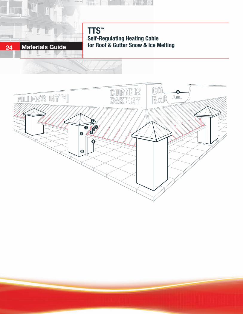
Basic Components:A TTS self-regulating roof and gutter snow and ice melting heat tracing system will typically include heating cable and components shown in the illustration and TTS cable ordering information below.
1
2
3
4
5
6
7
8
9
Ref # Part Number Description
1 TTS-8-1-OJ 8 W/FT @ 120V 1 TTS-8-2-OJ 8 W/FT @ 240V
Cable
Termination Kits 2 18-SXG-Kit1 Power Connection Gland Kit w/o Junction Box 8 ET-4S End Termination Kit HS-PBSK Inline Splice with Heat Shrink HS-TBSK T-Splice with Heat Shrink
Installation Accessories 3 AL TAPE 3M™
Aluminum Tape (2" X 180') in gutter 4 CL Caution Labels (25 Per Pack) 6 RG-CMC “P” Style Roof, Cable Mounting Clips (100/Bag) 5 RG-CRF Roof Clips, Cable Roof Fastener (25/Bag) 7 RG-DCH Downspout Cable Hanger
Controls 9 STC-DS2B Snow and Ice Sensor, Pole Mounted 9 STC-DS-8 Snow and Ice Sensor with a 10' Remote Lead Wire 9 RC3-0120-DP Weatherproof Indoor / Outdoor Thermostat
16 Ordering Information
1 Junction box appropriate for the application to be supplied by the installer.
TTS™
Self-Regulating Heating Cablefor Roof & Gutter Snow & Ice Melting
17
Materials Guide
ContentsIntroduction .......... ....................................................................................18
Creating a Materials List ............................................................................18
Step 1. Determine Level of Protection .................................................18
Step 2. Select the Proper TTS Heating Cable ......................................18
Step 3. Specify Locations for Power Connections ...............................19
Step 4. Choose TTS Installation Accessories.......................................19
Step 5. Establish Control Method ........................................................19
Tips .............................................................................................................24

TTS™
Self-Regulating Heating Cablefor Roof & Gutter Snow & Ice Melting
Creating a Materials List:The area that will require heat trac-ing is based somewhat on the size and shape of the building. A building with no overhangs, for example, may only need gutter and downspout protection while an overhang covering a building entrance that is subject to drifting may need complete coverage. Typically the areas susceptible to snow and ice dams consist of:
• Roof overhangs without gutters • Roof overhangs with gutters and downspouts • Gutters and downspouts only
Step 1: Identify the Area Requiring Snow and Ice Melting and Determine Level of Protection RequiredReview the plans and/or design of the facility to identify the areas that will require roof and gutter snow and ice melting. To establish the level of protection necessary, decide if the climate/installation conditions fall into the moderate or heavy levels based on the variables below:
18 Materials Guide
Introduction:This guide provides a basis for a roof and gutter snow and ice melting system. The amount of heating cable required and the performance of the system is highly dependent upon the following parameters:
• Geographical location of project
• Orientation of building to prevailing wind and weather
• Building and construction
• Degree of protection required1
If any variable falls into the heavy category, plan the system for heavy accumulation to ensure adequate protection for the building. Should weather conditions, the building’s design/orientation or the expected usage of the facility dictate, increase the amount of cable to be installed.
Step 2: Select Proper TTS Cable Based on:Operating Voltage: TTS self-regulating cables are available in two voltage groups: 110-120 Vac and 208-240 Vac. Determine what voltage is available for use with heat tracing.
Branch Circuit Breakers: Use Table 2.1, Cable Selection, to match the TTS circuit length with the available branch circuit breaker size. If a known branch circuit breaker size is being used, match this value with the corresponding TTS circuit length. If breaker size will be dictated by heating cable requirements, determine the optimal TTS circuit lengths based on the project size and cable layout.
Maximum Circuit Lengths: The maximum circuit lengths shown in Table 2.1 are based on TTS cable start-up at an ambient temperature of 7° C (20° F). Because the power output of TTS will vary to meet the needs of the surrounding environment, the operating load will vary.
Notes... 1. While entire roof areas can be electrically heat
traced for snow and ice removal, this guide addresses only roof overhangs, gutters and downspouts. Should your application require more area to be protected, contact a 3M representative.
Snowfall Rate Moderate (≤1"/hr.) Heavy (1-2"/hr.) Eave-to-Ridge Distance ≤20' 20-40' Size (width) of Gutter ≤6" 6-12"
TTS™
Self-Regulating Heating Cablefora Roof & Gutter Snow & Ice Melting
19
Materials Guide
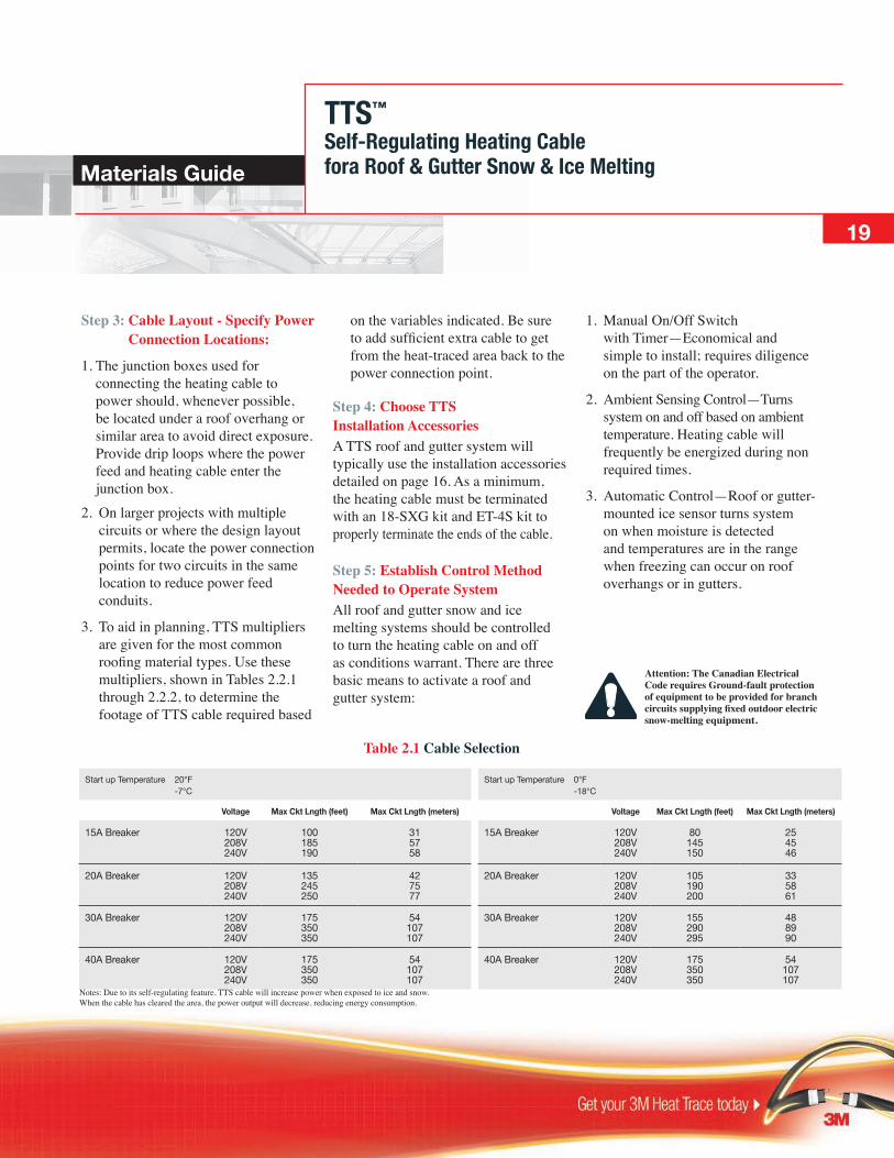
Step 3: Cable Layout - Specify Power Connection Locations:
1. The junction boxes used for connecting the heating cable to power should, whenever possible, be located under a roof overhang or similar area to avoid direct exposure. Provide drip loops where the power feed and heating cable enter the junction box.
2. On larger projects with multiple circuits or where the design layout permits, locate the power connection points for two circuits in the same location to reduce power feed conduits.
3. To aid in planning, TTS multipliers are given for the most common roofing material types. Use these multipliers, shown in Tables 2.2.1 through 2.2.2, to determine the footage of TTS cable required based
Attention: The Canadian Electrical Code requires Ground-fault protection of equipment to be provided for branch circuits supplying fixed outdoor electric snow-melting equipment.
on the variables indicated. Be sure to add sufficient extra cable to get from the heat-traced area back to the power connection point.
Step 4: Choose TTS Installation AccessoriesA TTS roof and gutter system will typically use the installation accessories detailed on page 16. As a minimum, the heating cable must be terminated with an 18-SXG kit and ET-4S kit to properly terminate the ends of the cable.
Step 5: Establish Control Method Needed to Operate SystemAll roof and gutter snow and ice melting systems should be controlled to turn the heating cable on and off as conditions warrant. There are three basic means to activate a roof and gutter system:
1. Manual On/Off Switch with Timer—Economical and simple to install; requires diligence on the part of the operator.
2. Ambient Sensing Control—Turns system on and off based on ambient temperature. Heating cable will frequently be energized during non required times.
3. Automatic Control—Roof or gutter-mounted ice sensor turns system on when moisture is detected and temperatures are in the range when freezing can occur on roof overhangs or in gutters.
Table 2.1 Cable Selection
Start up Temperature 20°F -7°C
Start up Temperature 0°F -18°C
Voltage Max Ckt Lngth (feet) Max Ckt Lngth (meters) Voltage Max Ckt Lngth (feet) Max Ckt Lngth (meters)
15A Breaker 120V 208V 240V
100 185 190
31 57 58
15A Breaker 120V 208V 240V
80 145 150
25 45 46
20A Breaker 120V 208V 240V
135 245 250
42 75 77
20A Breaker 120V 208V 240V
105 190 200
33 58 61
30A Breaker 120V 208V 240V
175 350 350
54 107 107
30A Breaker 120V 208V 240V
155 290 295
48 89 90
40A Breaker 120V 208V 240V
175 350 350
54 107 107
40A Breaker 120V 208V 240V
175 350 350
54 107 107
Notes: Due to its self-regulating feature, TTS cable will increase power when exposed to ice and snow. When the cable has cleared the area, the power output will decrease, reducing energy consumption.

TTS™
Self-Regulating Heating Cablefor Roof & Gutter Snow & Ice Melting20 Materials Guide
To determine the layout pattern for TTS heating cable on metal roofs, use Table 2.2.1 in conjunction with measurements of the spacing of the seams, corrugations or ridges in the roofing material. This spacing, combined with the desired level of protection, will determine what multiplier to use to determine the footage of cable required. (Heating cable does not have to be installed on every seam, corrugation, etc.) Be sure to add sufficient extra cable to reach the power connection point for each circuit.
To establish the amount of cable required, select the overhang distance that fits the application and follow this row across to the spacing pitch column that corresponds to the roofing material. The number where the row and column intersect is the multiplier for that application. Multiply this number by the number of linear feet of roof eave to be protected and add sufficient cable to reach the power supply junction box plus any additional cable to allow for on-site variations.
Spacing Pitch Overhang Distance 10" 12" 14" 16" 18" 20" 22" 24"
12"
18"
24"
30"
36"
4.2
5.4
6.6
7.8
9.0
3.7
4.7
5.7
6.7
7.7
3.3
4.2
5.0
5.9
6.7
3.0
3.8
4.5
5.3
6.0
Heavy Condition Multipliers Moderate Condition Multipliers
2.8
3.5
4.1
4.8
5.5
2.6
3.2
3.8
4.4
5.0
2.5
3.0
3.6
4.1
4.7
2.4
2.9
3.4
3.9
4.4
Table 2.2.1 Metal Roofs
TTS Cable
Roof
RG-CMC
Gutter Section Detail
TTS Cable Multipliers:Select a multiplier from the examples shown based on the type of roofing material utilized. If gutters and downspouts will also require protection, be sure to add the cable requirements (see Table 2.2.3) to the roof overhang footages.
Metal Roofs:Metal roofing materials such as standing seam or corrugated, as well as tile/concrete roofing materials that have distinct ridges or grooves, must be properly addressed when installing heat tracing. Metal roofs in particular pose an avalanche potential that could
damage the heating cable if it were installed in a serpentine pattern. To combat this, the cable is installed parallel to the standing seams or along the length of a corrugation. The partial sketch above depicts TTS cable as it would be installed on a standing seam metal roof.
Overhang Distance
How far up the roof the heating cable should travel may be determined by measuring the distance as shown at left. The heating cable should loop past the point where an imaginary line extending up from the inside wall would pass through the roof.

TTS™
Self-Regulating Heating Cablefor Roof & Gutter Snow & Ice Melting
21
Materials Guide
Shingle Roofs:All shingle roofs (fiberglass, flat tile or concrete shingle) can utilize heating cable installed in a serpentine pattern as detailed in the partial sketch below.
The heating cable may be attached to the roof and fascia with cable fasteners (Catalog No. RG-CRF) or similar devices held in place with suitable fasteners or adhesives. Care should be exercised to maintain the integrity of the roof.
To determine the layout pattern for TTS heating cable on shingle-style
roofs, use Table 2.2.2. Recommended moderate and heavy conditions multipliers have been shaded for each overhang distance. Should conditions dictate a specific pitch, multipliers for additional spacings have been included. Be sure to add sufficient extra cable to reach the power connection point for each circuit.
To establish the amount of cable required, select the row with the corresponding overhang distance and follow across to the multiplier that matches the level of protection desired. After selecting a multiplier, read the corresponding spacing pitch value at the top of the column.
Multiply this number by the number of linear feet of roof eave to be protected and add sufficient cable to reach the power supply junction box.
Table 2.2.2 Shingle Roofs
Spacing Pitch Overhang Distance 10" 16" 18" 20" 22" 24" 26" 28"
18"
24"
30"
36"
42"
3.3
4.2
5.0
5.8
6.7
3.0
3.7
4.4
5.1
5.9
2.7
3.3
3.9
4.6
5.2
2.4
3.0
3.6
4.1
4.7
2.3
2.8
3.3
3.8
4.3
2.1
2.6
3.0
3.5
4.0
NR
2.4
2.8
3.3
3.7
NR
2.3
2.7
3.1
3.5
Heavy Condition MultipliersRate of Snow Fall 2"/hr
Moderate Condition MultipliersRate of Snow Fall 1"/hr
Attention: Where conditions dictate (heavy snow loads, steep roof slopes, smooth roofing materials or long eave-to-ridge distances), snow fences and/or snow brakes should be considered to prevent/reduce the potential for damage to the cable and/or facility.
TTS™
Self-Regulating Heating Cablefor Roof & Gutter Snow & Ice Melting22 Materials Guide
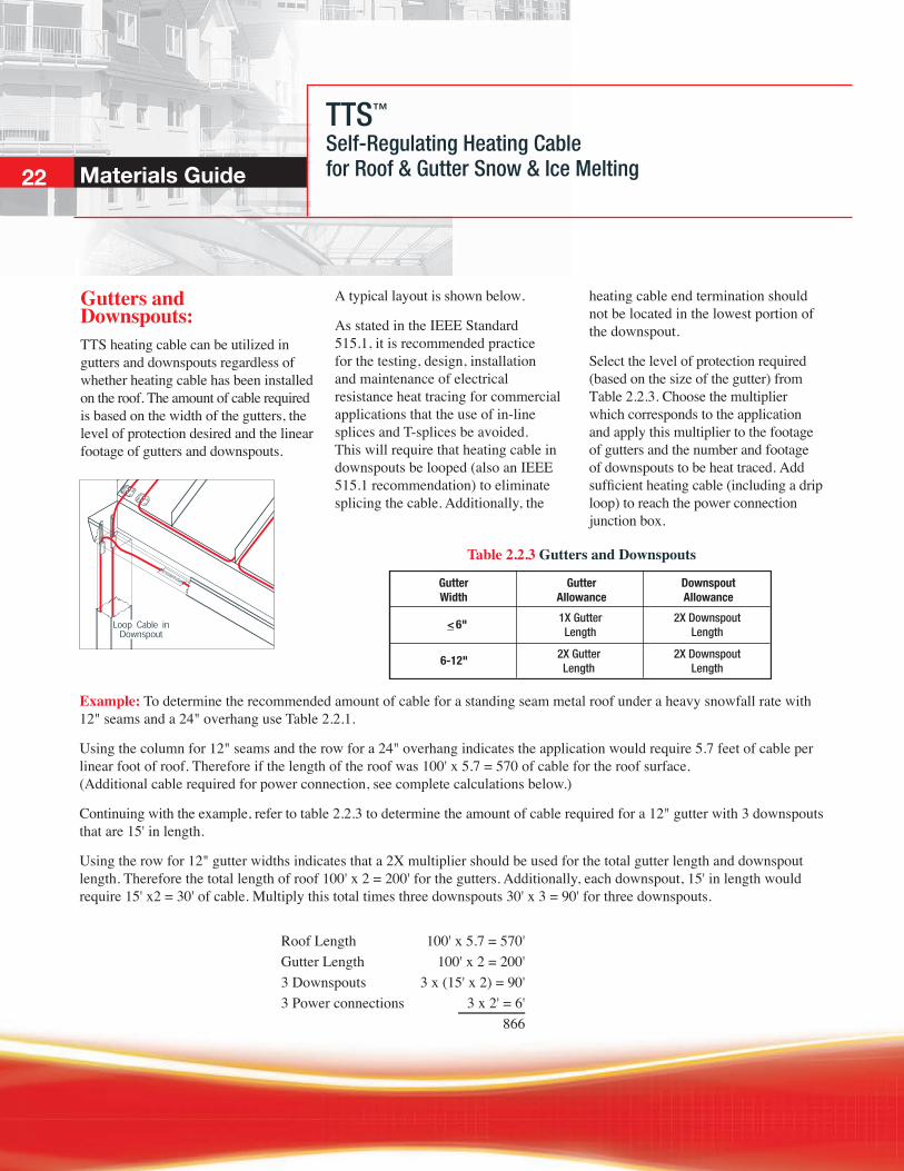
Gutters and Downspouts:TTS heating cable can be utilized in gutters and downspouts regardless of whether heating cable has been installed on the roof. The amount of cable required is based on the width of the gutters, the level of protection desired and the linear footage of gutters and downspouts.
A typical layout is shown below.
As stated in the IEEE Standard 515.1, it is recommended practice for the testing, design, installation and maintenance of electrical resistance heat tracing for commercial applications that the use of in-line splices and T-splices be avoided. This will require that heating cable in downspouts be looped (also an IEEE 515.1 recommendation) to eliminate splicing the cable. Additionally, the
GutterWidth
6-12"
<_ 6"
GutterAllowance
DownspoutAllowance
1X GutterLength
2X DownspoutLength
2X DownspoutLength
2X GutterLength
Table 2.2.3 Gutters and Downspouts
heating cable end termination should not be located in the lowest portion of the downspout.
Select the level of protection required (based on the size of the gutter) from Table 2.2.3. Choose the multiplier which corresponds to the application and apply this multiplier to the footage of gutters and the number and footage of downspouts to be heat traced. Add sufficient heating cable (including a drip loop) to reach the power connection junction box.
Example: To determine the recommended amount of cable for a standing seam metal roof under a heavy snowfall rate with 12" seams and a 24" overhang use Table 2.2.1.
Using the column for 12" seams and the row for a 24" overhang indicates the application would require 5.7 feet of cable per linear foot of roof. Therefore if the length of the roof was 100' x 5.7 = 570 of cable for the roof surface. (Additional cable required for power connection, see complete calculations below.)
Continuing with the example, refer to table 2.2.3 to determine the amount of cable required for a 12" gutter with 3 downspouts that are 15' in length.
Using the row for 12" gutter widths indicates that a 2X multiplier should be used for the total gutter length and downspout length. Therefore the total length of roof 100' x 2 = 200' for the gutters. Additionally, each downspout, 15' in length would require 15' x2 = 30' of cable. Multiply this total times three downspouts 30' x 3 = 90' for three downspouts.
Roof Length 100' x 5.7 = 570' Gutter Length 100' x 2 = 200' 3 Downspouts 3 x (15' x 2) = 90' 3 Power connections 3 x 2' = 6' 866
TTS™
Self-Regulating Heating Cablefor Roof & Gutter Snow & Ice Melting
23
Materials Guide
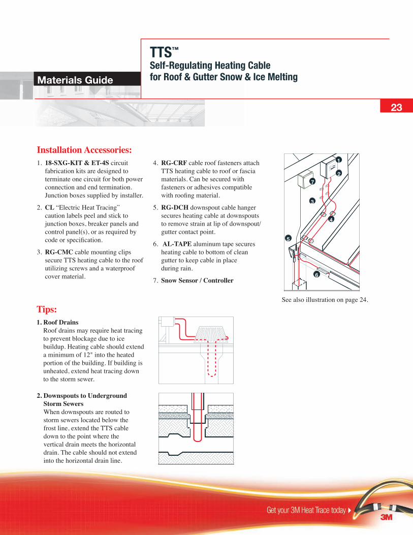
Installation Accessories:1. 18-SXG-KIT & ET-4S circuit fabrication kits are designed to terminate one circuit for both power connection and end termination. Junction boxes supplied by installer.
2. CL “Electric Heat Tracing” caution labels peel and stick to junction boxes, breaker panels and control panel(s), or as required by code or specification.
3. RG-CMC cable mounting clips secure TTS heating cable to the roof utilizing screws and a waterproof cover material.
4. RG-CRF cable roof fasteners attach TTS heating cable to roof or fascia materials. Can be secured with fasteners or adhesives compatible with roofing material.
5. RG-DCH downspout cable hanger secures heating cable at downspouts to remove strain at lip of downspout/ gutter contact point.
6. AL-TAPE aluminum tape secures heating cable to bottom of clean gutter to keep cable in place during rain.
7. Snow Sensor / Controller
See also illustration on page 24.
72
3
4
5
6
1
Tips: 1. Roof Drains
Roof drains may require heat tracing to prevent blockage due to ice buildup. Heating cable should extend a minimum of 12" into the heated portion of the building. If building is unheated, extend heat tracing down to the storm sewer.
2. Downspouts to Underground Storm Sewers When downspouts are routed to storm sewers located below the frost line, extend the TTS cable down to the point where the vertical drain meets the horizontal drain. The cable should not extend into the horizontal drain line.
TTS™
Self-Regulating Heating Cablefor Roof & Gutter Snow & Ice Melting24 Materials Guide
21
5
6
7
43
9
8

KSR™
Self-Regulating Heating Cablefor Surface Snow & Ice Melting
25
Ordering Information
Description:Cut-to-length KSR self-regulating heating cables are designed to provide snow and ice protection in concrete and asphalt applications. Designed and approved specifically for direct burial, KSR cable withstands the abuse encountered during installation.
Areas of Application:• Business entrance and exit locations • Ramps and handicap access routes • Stairs and footpaths • Loading docks • Driveways and garage entrances • Critical access routes
Ratings:Available watt densities.................................................................... 88 w/m @ 0° C (In concrete) (27 w/ft @32° F) Supply Voltages......................................................................................208-240 Vac Minimum installation temperature.................................................... -40° C (-40° F) Minimum bend radius........................................................................ 32 mm (1.25")
Certifications / Approvals:Canadian Standards Association Ordinary (Non-Classified) LocationsMeets or exceeds - IEEE 515.1 - UL 1588CSA 130.3

26 Ordering Information
KSR™
Self-Regulating Heating Cablefor Surface Snow & Ice Melting
Basic Components:A KSR self-regulating surface snow and ice melting system will typically include heating cable and components shown in the illustration and KSR ordering information below.
Ref # Part Number Description
1 KSR-2-OJ 208 - 240 Vac
Cable
Termination Kits 2 KSR-CFK1 Power Connection / End Termination Kit w/o Junction Box 3 KSR-EJK Expansion Joint Kit 6 KSR-SK-DB Splice Kit
Installation Accessories 4 CL Caution Labels (25 Per Pack) 5 CT8BK50-C 3M™ Weather Resistant Cable Ties (100 per Pack)
Controls 7 STC-DS2B Snow and Ice Sensor, Pole Mounted 7 R3C-0120-DP Weatherproof Indoor / Outdoor Thermostat
2
1
3
4
5
6
71 Junction box appropriate for the application to be supplied by the installer.
Materials Guide
KSR™
Self-Regulating Heating Cablefor Surface Snow & Ice Melting
27
ContentsIntroduction .............................................................................................. 28
Creating a Materials List
Step 1: Identify Area Requiring Snow & Ice Melting ....................... 29 Step 2: Determine Level of Protection Required ............................... 30 Step 3: Determine Length of Cable Required and Circuit Lengths ... 31 Step 4: Locate Power Connections and End Terminations; Lay Out Cable .............................................................................. 32 Step 5: Establish Control Method to Operate System ............................. 34
Cable Spacing Selection Guide ................................................................ 35
KSR™
Self-Regulating Heating Cablefor Surface Snow & Ice Melting28 Materials Guide
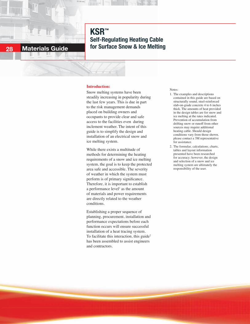
Introduction:Snow melting systems have been steadily increasing in popularity during the last few years. This is due in part to the risk management demands placed on building owners and occupants to provide clear and safe access to the facilities even during inclement weather. The intent of this guide is to simplify the design and installation of an electrical snow and ice melting system.
While there exists a multitude of methods for determining the heating requirements of a snow and ice melting system, the goal is to keep the protected area safe and accessible. The severity of weather in which the system must perform is of primary significance. Therefore, it is important to establish a performance level1 as the amount of materials and power requirements are directly related to the weather conditions.
Establishing a proper sequence of planning, procurement, installation and performance expectations before each function occurs will ensure successful installation of a heat tracing system. To facilitate this interaction, this guide2 has been assembled to assist engineers and contractors.
Notes: 1. The examples and descriptions
contained in this guide are based on structurally sound, steel-reinforced slab-on-grade concrete 4 to 6 inches thick. The amounts of heat provided in the design tables are for snow and ice melting at the rates indicated. Prevention of accumulation from drifting snow or runoff from other sources may require additional heating cable. Should design conditions vary from those shown, please contact a 3M representative for assistance.
2. The formulas, calculations, charts, tables and layout information presented have been researched for accuracy; however, the design and selection of a snow and ice melting system are ultimately the responsibility of the user.

KSR™
Self-Regulating Heating Cablefor Surface Snow & Ice Melting
29
Materials Guide
Creating a Materials List: The following five steps outline the selection process for a a snow melting system using KSR heating cable.
An example following each design step will take the reader through the process of evaluating, planning and specifying a snow melting system.
While the example shown is small, the process would be the same regardless of the area to be protected. The design example includes flat surfaces, stairs, a ramp, expansion joints in the concrete and the need to bring power from a specific location.
Figure 3.1.1
Step 1: Identify Area Requiring Snow and Ice MeltingDetermining the area that will require heat tracing is based somewhat on the traffic expected during snow and ice accumulation periods plus the layout of the area and its location relevant to prevailing winds and susceptibility to drifting.
Identify the existence of electric snow and ice melting heat tracing cable in the Concrete Curbs, Walks and Paving portions of the project specification. In addition, the project drawings (both electrical and site work) should include reference to the existence of electric heat tracing.
Example: The public/employee entrance to a facility is exposed to weather with only the area directly in front of the entry doors covered by a roof. The building is adjacent to the concrete on two sides with the handicap access ramp (which has a retaining wall) located on the third side. Snow removal could only be accomplished at the curb and parking area, a choice found undesirable for various reasons.
To maintain a clear entrance, the landing, stairs, ramp and approach area will require snow melting. The area in front of the doors will be heat traced to prevent accumulation also from drifting and tracking.

Regardless of geographical location or size of area to be protected, the heating requirements for snow melting are affected by four primary factors:
• Rate of snowfall • Ambient temperature • Wind velocity • Humidity
Establishing the level of protection required for a facility requires an understanding of the type of service the area will encounter and under what type of weather conditions the snow and ice melting system must perform1. 3M developed Table 3.2.1 KSR Cable Spacing (using information from IEEE Standard 515.1-1995 and ASHRAE) to simplify the selection process for determining the level of protection required. An additional table can be found in the Cable Spacing Selection Guide on page 35.
Since the example shown is a public / employee entrance it would be considered a noncritical area (Table 3.2.1) where snow removal is convenient but not essential. Additionally, if the example is located in Vancouver, BC, where the snowfall severity would fall into the “moderate” category of 1" per hour, the heating cable should be installed on 9" center-to-center spacing.
If the system is to meet ASHRAE requirements, refer to the Cable Spacing Selection Guide on page XX. Based on this data, for Vancouver, 9" center-to-center spacing of KSR cable indicates that for approximately 84% of snowfall hours the surface will remain clear.
Applications where snow removal is a convenience but not essential. Examples include building entrances, loading docks and parking garage ramps.
Applications where safe access is essential. Examples include hospital emergency entrances, train loading platforms and fire station driveways.
Notes:
1. Additional heat may be needed if the area will be subject to drifting or moisture runoff from another source. No allowance has been made for back or edge loss. Both back and edge loss will occur to varying degrees on every application. The amount and extent of loss is affected by soil types, frost line depth, shape and size of the area, plus the location of the area as it relates to other structures and wind.
2. Spacing as shown in Table 3.2.1 will provide a completely melted surface for the concrete area under typical snowfall weather conditions–ambient temperatures between -6° C (20° F) and 1° C (34° F) with wind speeds of 5 to 15 mph. Should the ambient temperature fall below -6° C (20° F) during the snowstorm, some snow accumulation could occur but will be melted at the rate of fall.
Snowfall Severity KSR Cable Spacing
Category Rate of Snowfall Noncritical Critical
Light ½"/hour 12" O.C. 7½" O.C
Moderate 1"/hour 9" O.C. 6" O.C.
Heavy 2"/hour 6" O.C. 6" O.C.
Table 3.2.1 KSR Cable Spacing2
KSR™
Self-Regulating Heating Cablefor Surface Snow & Ice MeltingMaterials Guide30
O.C. = On Centre
KSR™
Self-Regulating Heating Cablefor Surface Snow & Ice MeltingMaterials Guide
31
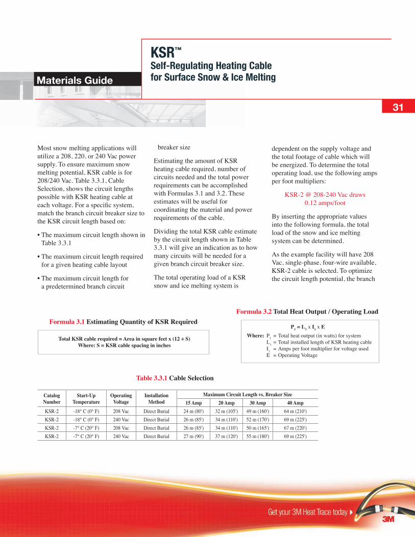
Most snow melting applications will utilize a 208, 220, or 240 Vac power supply. To ensure maximum snow melting potential, KSR cable is for 208/240 Vac. Table 3.3.1, Cable Selection, shows the circuit lengths possible with KSR heating cable at each voltage. For a specific system, match the branch circuit breaker size to the KSR circuit length based on:
• The maximum circuit length shown in Table 3.3.1
• The maximum circuit length required for a given heating cable layout
• The maximum circuit length for a predetermined branch circuit
Formula 3.1 Estimating Quantity of KSR Required
Total KSR cable required = Area in square feet x (12 ÷ S)Where: S = KSR cable spacing in inches
Table 3.3.1 Cable Selection
Catalog Number
Start-Up Temperature
Operating Voltage
Installation Method
Maximum Circuit Length vs. Breaker Size15 Amp 20 Amp 30 Amp 40 Amp
KSR-2 -18° C (0° F) 208 Vac Direct Burial 24 m (80') 32 m (105') 49 m (160') 64 m (210')KSR-2 -18° C (0° F) 240 Vac Direct Burial 26 m (85') 34 m (110') 52 m (170') 69 m (225')KSR-2 -7° C (20° F) 208 Vac Direct Burial 26 m (85') 34 m (110') 50 m (165') 67 m (220')KSR-2 -7° C (20° F) 240 Vac Direct Burial 27 m (90') 37 m (120') 55 m (180') 69 m (225')
breaker size
Estimating the amount of KSR heating cable required, number of circuits needed and the total power requirements can be accomplished with Formulas 3.1 and 3.2. These estimates will be useful for coordinating the material and power requirements of the cable.
Dividing the total KSR cable estimate by the circuit length shown in Table 3.3.1 will give an indication as to how many circuits will be needed for a given branch circuit breaker size.
The total operating load of a KSR snow and ice melting system is
dependent on the supply voltage and the total footage of cable which will be energized. To determine the total operating load, use the following amps per foot multipliers:
KSR-2 @ 208-240 Vac draws 0.12 amps/foot
By inserting the appropriate values into the following formula, the total load of the snow and ice melting system can be determined.
As the example facility will have 208 Vac, single-phase, four-wire available, KSR-2 cable is selected. To optimize the circuit length potential, the branch
Formula 3.2 Total Heat Output / Operating Load
P1 = L1 x I1 x EWhere: P1 = Total heat output (in watts) for system L1 = Total installed length of KSR heating cable I1 = Amps per foot multiplier for voltage used E = Operating Voltage

Step 4: Specify Locations for Power Connections /End Terminations and Lay Out Cable on Scaled DrawingJunction Boxes: KSR power connection and end termination points must be located inside suitable junction boxes located above the moisture line. Depending on the size of the junction box, several power connections and/or end terminations can be located within the same box.
• Protect heating cable with rigid metallic conduit (one cable per conduit) between junction box and area being heated. • Extend conduit (equipped with bushings on each end) a minimum of 12" into slab.
A typical junction box and conduit assembly is shown in Figure 3.4.1.
KSR Layout: When the location of the junction boxes for power connections and end terminations has been established, lay out the heating cable.
• Use a scaled drawing or sketch to simplify the process. • Base layout on center-to-center spacing selected in Step 1. • Do not exceed circuit lengths shown in Table 3.3.1. • Locate cable 2" to 4" below finished concrete surface. • For standard slab (4" to 6" thick), place KSR directly on top of reinforcing steel. • Attach to steel with nylon tie wraps on 24" (minimum) intervals.
Expansion Joints: Unless the slab is of monolithic construction, there will be expansion or construction joints which must be taken into account to prevent damage to the cable (Figure 3.4.2).
• Keep expansion joint kit use to a minimum by utilizing proper layout techniques.• Mark drawings with locations of expansion and construction joints.
• Allow an extra 3' of KSR cable for each expansion joint kit.
Figure 3.4.1 Junction Box/Conduit
Figure 3.4.2 Expansion Joint Kit Section
KSR™
Self-Regulating Heating Cablefor Surface Snow & Ice Melting32 Materials Guide
circuit breakers will be sized to reflect the layout of the cable (see Step 4 for cable layout).
Using Formula 3.1:
Total KSR cable required = Area in ft2 x (12 ÷ S)
and substituting values for the design example:
Total KSR cable required = 600 ft2 x (12 ÷ 9)
the total footage of cable can be estimated:
Total KSR cable required = 800 linear feet (plus allowance from Note 2)
Using Formula 3.2:
Pt = Lt x If x E
and substituting values for the design example:
Pt = 840 ft x 0.12 amps/ft x 208 Vac
the total kilowatt demand for the system can be estimated:
Pt = 21 kwNotes: 1.When calculating the amount of KSR heating cable required based on the square footage of the area, allowances should be included for making connections within junction boxes and for any expansion joint kits necessary to complete the layout.
KSR™
Self-Regulating Heating Cablefor Surface Snow & Ice Melting
33
Materials Guide
Figure 3.4.3 Detail at Steps
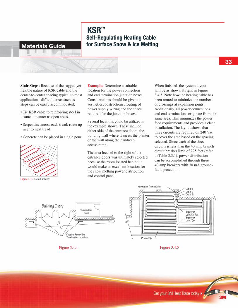
Stair Steps: Because of the rugged yet flexible nature of KSR cable and the center-to-center spacing typical to most applications, difficult areas such as steps can be easily accommodated.
• Tie KSR cable to reinforcing steel in same manner as open areas.
• Serpentine across each tread; route up riser to next tread.
• Concrete can be placed in single pour.
Figure 3.4.5Figure 3.4.4
Example: Determine a suitable location for the power connection and end termination junction boxes. Considerations should be given to aesthetics, obstructions, routing of power supply wiring and the space required for the junction boxes.
Several locations could be utilized in the example shown. These include either side of the entrance doors, the building wall where it meets the planter or the wall along the handicap access ramp.
The area located to the right of the entrance doors was ultimately selected because the room located behind it would make an excellent location for the snow melting power distribution and control panel.
When finished, the system layout will be as shown at right in Figure 3.4.5. Note how the heating cable has been routed to minimize the number of crossings at expansion joints. Additionally, all power connections and end terminations originate from the same area. This minimizes the power feed requirements and provides a clean installation. The layout shows that three circuits are required on 240 Vac to cover the area based on the spacing selected. Since each of the three circuits is less than the 40 amp branch circuit breaker limit of 225 feet (refer to Table 3.3.1), power distribution can be accomplished through three 40 amp breakers with 30 mA ground-fault protection.
Energizing the Heating Cable: All snow melting systems should be controlled to turn the heating cable on and off as conditions warrant. There are three basic means to activate a snow melting system:
A. Manual
• On/Off Switch–Simple to install and economical to purchase; requires diligence on the part of the operator.
B. Automatic
• Ambient Sensing Control–Turns system on and off based on ambient temperature. Heating cable will frequently be energized during non required times.
• Automatic Control–Turns system on when precipitation is detected and temperatures are in the range where snow or freezing rain is likely.
Some applications, such as truck scales and loading zones, are subject to freezing water or slush accumulation
Step 5: Establish Control Method Needed to Operate the System
even though no precipitation is falling. To properly deal with these conditions, a custom designed control system is typically required and the designer should contact 3M for assistance.
Example: Because the facility will be occupied during normal weekday business hours, the system is to be controlled automatically. To accomplish this, an STC-DS-2B snow and ice sensor will be utilized.
A power distribution and contactor panel would consist of a main 3 pole breaker, a 3 pole contactor and three 40 amp branch circuit breakers equipped with 30 mA ground-fault protection. The panel would also be equipped with a hand/off/auto switch plus lights to indicate system status.
Because the panel will be located indoors, a NEMA 12 enclosure is suitable for the panel. If the panel was to be installed outside, a NEMA 4 or 4X enclosure would be required.
Providing Power Distribution and Contactors: When a snow melting system requires four or more heat tracing circuits, it is recommended
that a dedicated power distribution and contactor panel be utilized. By keeping the snow melting circuit breakers in a dedicated panel, several design and operation advantages will occur:
• The panel can utilize a main circuit breaker and contactor which permits a complete shut- down of the system for out-of- season times as well as routine maintenance checks.
• A dedicated snow melting panel will reduce the potential of non- authorized access.
• A dedicated snow melting panel can be located close to the point of use and reduce power feed wiring and conduit necessary to energize the system.
• In critical snow melting applications, the panel can be equipped with a monitor and alarm feature that will verify the integrity of the circuit and the status of the ground-fault branch circuit breakers.
KSR™
Self-Regulating Heating Cablefor Surface Snow & Ice Melting34 Materials Guide

KSR™
Self-Regulating Heating Cablefor Surface Snow & Ice Melting
35
Materials Guide
Cable Spacing Selection Guide:As an alternate to the KSR cable spacing selection chart shown in Step 2, a snow and ice melting system can be designed using the information presented in Chapter 45 of the ASHRAE Applications Handbook. In their tutorial on snow and ice melting, ASHRAE compiled a list of 33 cities with weather data for each. Using this information, 3M developed the table below to show the effect of various power (heat) outputs.
The values presented in Table 1, Data for Determining Operating Characteristics of Snow Melting Systems (ASHRAE 1991 Applications Handbook, Chapter 45), and detailed below show the calculated percentage of snowfall hours that a surface will remain clear of snow when a predetermined level of heat is installed. This method is very useful when comparing what additional benefit, in terms of keeping an area
clear, is obtained when the watts/ft2 is increased.
While it is necessary to have weather data to establish values for temperature, wind, humidity and snowfall, ASHRAE cautions that a snow melting system should not be designed based on the annual averages or worst weather conditions encountered. Doing so will result in a system unnecessarily over designed for a majority of applications.
6" O.C. 9" O.C. 12" O.C.
Calgary, Alberta
Edmonton, Alberta
Halifax, Nova Scotia
Montreal, Quebec
Ottawa, Ontario
Quebec City, Quebec
St.Johns NFLD,
Sudbury, Ontario
Toronto, Ontario
Vancouver, B.C.
Winnipeg, Manitoba
40 45 50 55 60 65 70 75 80 85 90 95 100
Percentage of Snowfall Hours Surface Is Clear With KSR Heat Tracing Cable Spacing as Indicated
Cable Spacing Selection Guide

HSX™ Self-Regulating Heating Cablefor Hot Water Temperature Maintenance36 Ordering Information
Description:HSX 2100 series cut-to-length self-regulating heating cables are specifically designed to maintain hot water supply piping at desired nominal maintenance temperatures. With 14 AWG bus wires, HSX 2100 series can reduce the number of circuits required to install an electric heat-traced system. Simply match the hot water maintenance temperature with the corresponding colour-coded cable (Blue/Green/Red) and insulate.
Application:• Energy efficient alternate to recirculation pipe systems • Ideal for installations with multiple maintain temperatures • Maintain hot water at three temperature levels: • 40° C, ie Nursing Homes • 50° C, ie Hotels • 60° C, ie Kitchens
Ratings:Maintain Temperatures.................................................................... 40, 50, or 60° C (104, 122, 140° F) Supply Voltages.............................................................................120, 208, 240 Vac Minimum installation temperature.................................................... -50° C (-40° F) Minimum bend radius.............................................................................13 mm (.5")
For more information about this cable and its applications, please contact your 3M representative.
Certifications / Approvals:Canadian Standards Association Ordinary LocationsMeets or exceeds - IEEE 515.1 - UL 1588CSA 130.3
Data Sheet
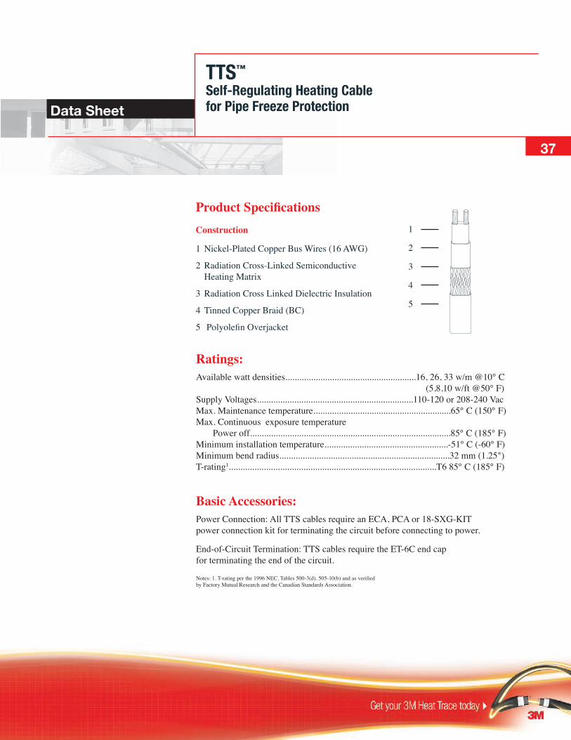
Product SpecificationsConstruction
1 Nickel-Plated Copper Bus Wires (16 AWG)
2 Radiation Cross-Linked Semiconductive Heating Matrix
3 Radiation Cross Linked Dielectric Insulation
4 Tinned Copper Braid (BC)
5 Polyolefin Overjacket
Ratings:Available watt densities........................................................16, 26, 33 w/m @10° C (5,8,10 w/ft @50° F) Supply Voltages...................................................................110-120 or 208-240 Vac Max. Maintenance temperature...........................................................65° C (150° F) Max. Continuous exposure temperature Power off......................................................................................85° C (185° F) Minimum installation temperature.....................................................-51° C (-60° F) Minimum bend radius.........................................................................32 mm (1.25") T-rating1.........................................................................................T6 85° C (185° F)
Basic Accessories:Power Connection: All TTS cables require an ECA, PCA or 18-SXG-KIT power connection kit for terminating the circuit before connecting to power.
End-of-Circuit Termination: TTS cables require the ET-6C end cap for terminating the end of the circuit.
Notes: 1. T-rating per the 1996 NEC, Tables 500-3(d), 505-10(b) and as verified by Factory Mutual Research and the Canadian Standards Association.
1
2
3
4
5
TTS™
Self-Regulating Heating Cablefor Pipe Freeze Protection
37
49
TTS™
Self-Regulating Heating Cablefor Pipe Freeze Protection
Certifications / Approvals:Canadian Standards Association Ordinary (Non-Classified) Locations Hazardous (Classified) Locations Class I, Division 2, Groups A, B, C and D - Class II, Division 2, Groups F and G Meets or exceeds - IEEE 515, IEEE 515.1 - UL 1588 CSA 130.3
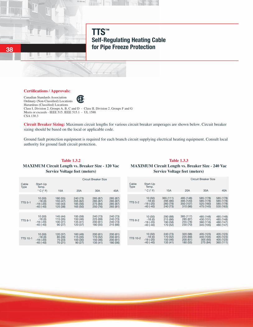
Circuit Breaker Sizing: Maximum circuit lengths for various circuit breaker amperages are shown below. Circuit breaker sizing should be based on the local or applicable code.
Ground fault protection equipment is required for each branch circuit supplying electrical heating equipment. Consult local authority for ground fault circuit protection.
38
Table 1.3.3 MAXIMUM Circuit Length vs. Breaker Size - 240 Vac
Service Voltage feet (meters)
Table 1.3.2 MAXIMUM Circuit Length vs. Breaker Size - 120 Vac
Service Voltage feet (meters)
TTS 5-1
TTS 8-1
TTS 10-1
Circuit Breaker SizeCableType
Start-Up Temp.
30A20A15A° C (° F) 40A
10 (50)-18 (0)
-19 (-20)-40 (-40)
180 (55)155 (47)140 (43)125 (38)
240 (73)205 (62)185 (56)165 (50)
285 (87)285 (87)275 (84)250 (76)
285 (87)285 (87)285 (87)265 (81)
10 (50)-18 (0)
-19 (-20)-40 (-40)
145 (44)115 (35)100 (31)
90 (27)
195 (59)150 (46)135 (41)120 (37)
240 (73)225 (69)200 (61)180 (55)
240 (73)240 (73)240 (73)215 (66)
10 (50)-18 (0)
-19 (-20)-40 (-40)
120 (37)85 (26)75 (23)70 (21)
160 (49)115 (35)100 (30)
90 (27)
200 (61)170 (52)150 (46)135 (41)
200 (61)200 (61)200 (61)180 (56)
TTS 5-2
TTS 8-2
TTS 10-2
Circuit Breaker SizeCableType
Start-Up Temp.
30A20A15A° C (° F) 40A
10 (50)-18 (0)
-19 (-20)-40 (-40)
365 (111)295 (90)260 (79)240 (73)
485 (148)395 (120)350 (107)
315 (96)
385 (117)285 (87)255 (78)230 (70)
585 (178)585 (178)525 (160)475 (145)
585 (178)585 (178)585 (178)535 (163)
10 (50)-18 (0)
-19 (-20)-40 (-40)
290 (88)215 (66)190 (58)170 (52)
485 (148)430 (131)380 (116)345 (105)
485 (148)485 (148)480 (147)480 (147)
10 (50)-18 (0)
-19 (-20)-40 (-40)
240 (73)170 (52)150 (46)135 (41)
320 (98)225 (69)200 (61)180 (55)
405 (123)340 (104)
305 (93)275 (84)
405 (123)405 (123)405 (123)365 (111)

Data Sheet
Product SpecificationsConstruction
1 Nickel-Plated Copper Bus Wires (16 AWG)
2 Radiation Cross-Linked Semiconductive Heating Matrix
3 Radiation Cross Linked Dielectric Insulation
4 Tinned Copper Braid (BC)
5 Polyolefin Overjacket
Ratings:Available watt densities ................................................................... 26 w/m @10° C
(8 w/ft @50° F) Supply Voltages ....................................................................110-120 or 208-240 Vac Minimum installation temperature ..................................................... -51° C (-60° F) Minimum bend radius .........................................................................32 mm (1.25")
Basic Accessories:Power Connection: All TTS cables require an 18-SXG-KIT power connection kit for terminating the circuit before connecting to power.
End-of-Circuit Termination: TTS cables require the ET-4S end cap for terminating the end of the circuit.
Notes: 1. T-rating per the 1996 NEC, Tables 500-3(d), 505-10(b) and as verified by Factory Mutual Research and the Canadian Standards Association.
1
2
3
4
5
TTS™
Self-Regulating Heating Cablefor Roof & Gutter Snow & Ice Melting
39
TTS™
Self-Regulating Heating Cablefor Roof & Gutter Snow & Ice Melting
Certifications / Approvals:Canadian Standards Association Ordinary (Non-Classified) Locations Hazardous (Classified) Locations Class I, Division 2, Groups A, B, C and D - Class II, Division 2, Groups F and G Meets or exceeds - IEEE 515, IEEE 515.1 - UL 1588 CSA 130.3
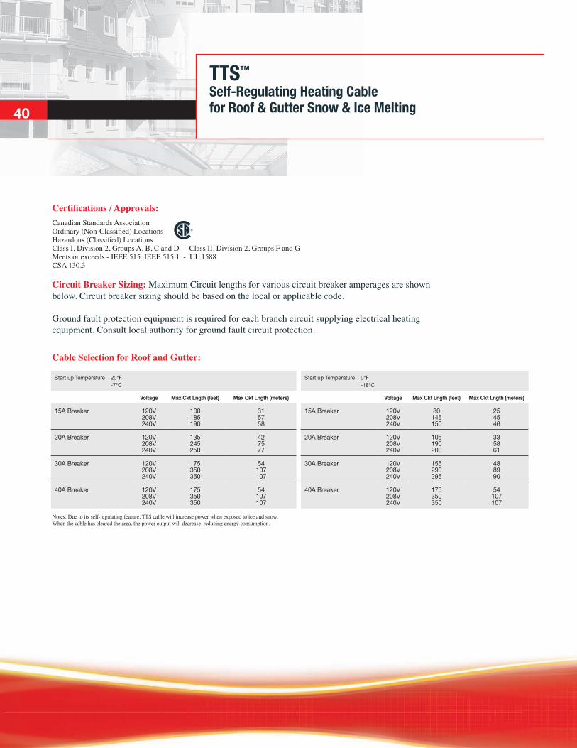
Circuit Breaker Sizing: Maximum Circuit lengths for various circuit breaker amperages are shown below. Circuit breaker sizing should be based on the local or applicable code.
Ground fault protection equipment is required for each branch circuit supplying electrical heating equipment. Consult local authority for ground fault circuit protection.
51
Cable Selection for Roof and Gutter:
Start up Temperature 20°F -7°C
Start up Temperature 0°F -18°C
Voltage Max Ckt Lngth (feet) Max Ckt Lngth (meters) Voltage Max Ckt Lngth (feet) Max Ckt Lngth (meters)
15A Breaker 120V 208V 240V
100 185 190
31 57 58
15A Breaker 120V 208V 240V
80 145 150
25 45 46
20A Breaker 120V 208V 240V
135 245 250
42 75 77
20A Breaker 120V 208V 240V
105 190 200
33 58 61
30A Breaker 120V 208V 240V
175 350 350
54 107 107
30A Breaker 120V 208V 240V
155 290 295
48 89 90
40A Breaker 120V 208V 240V
175 350 350
54 107 107
40A Breaker 120V 208V 240V
175 350 350
54 107 107
Notes: Due to its self-regulating feature, TTS cable will increase power when exposed to ice and snow. When the cable has cleared the area, the power output will decrease, reducing energy consumption.
40

Notes: Due to its self-regulating feature, TTS cable will increase power when exposed to ice and snow. When the cable has cleared the area, the power output will decrease, reducing energy consumption.
KSR™
Self-Regulating Heating Cablefor Surface Snow & Ice MeltingData Sheet
Certifications / Approvals:Canadian Standards Association
Construction:
Silicone Rubber Outer Jacket Nickel-Plated Copper Bus Wires
Tinned Copper Braid Semiconductive Heating Matrix
Fluoropolymer Insulation
Cable Selection:
Ratings:Bus wire .......................................................................................................................................... 16 AWG nickel-plated copper Heating Core ..................................................................................................................................semiconductive heating matrix Primary dielectric insulation .......................................................................................................high performance fluoropolymer Metallic braid ............................................................................................................................................................ tinned copper Outer jacket ............................................................................................................................................................. silicone rubber Minimum bend radius ..............................................................................................................................................32 mm (1.25") Supply voltage ............................................................................................................................................................208-277 Vac Circuit protection .............................................................................................................30 mA ground-fault protection required
Note: Consult your local or applicable electrical code regarding ground fault protection.
41
Catalog Number
Start-Up Temperature
Operating Voltage
Installation Method
Maximum Circuit Length vs. Breaker Size15 Amp 20 Amp 30 Amp 40 Amp
KSR-2 -18° C (0° F) 208 Vac Direct Burial 24 m (80') 32 m (105') 49 m (160') 64 m (210')KSR-2 -18° C (0° F) 240 Vac Direct Burial 26 m (85') 34 m (110') 52 m (170') 69 m (225')KSR-2 -7° C (20° F) 208 Vac Direct Burial 26 m (85') 34 m (110') 50 m (165') 67 m (220')KSR-2 -7° C (20° F) 240 Vac Direct Burial 27 m (90') 37 m (120') 55 m (180') 69 m (225')

HSX™
Self-Regulating Heating Cablefor Hot Water Temperature Maintenance
Bus Wire
Radiation Cross-Linked Polyolefin Insulation Radiation Cross-Linked Heating Core
Tinned Copper BraidPolyolefin Outer Jacket Aluminum Foil Wrap
Construction:
Cable Selection:
53
Ratings:Bus wire ............................................................................................................................................14AWG nickel-plated copper Metallic braid ...................................................................................................................14 AWG (equivalent size) tinned copper Outer jacket ..............................................................................................................................polyolefin; 1 mm (0.040") nominal Minimum bend radius ................................................................................................................................................ 13 mm (0.5") Supply voltage .........................................................................................................................................................120 or 208 Vac Circuit protection1 .............................................................................................................30 mA ground-fault protection required
42
Certifications / Approvals:Canadian Standards Association
Note: Consult your local or applicable electrical code regarding ground fault protection.
Catalog Number
Outer Jacket
Operating Voltage
Nominal Maintain Temperature
Ambient Range
Maximum Circuit Length vs. Breaker Size
15 Amp 20 Amp
HSX 2105-2 Blue 240 Vac 41° C (105° F) 24°-27° C (75°-80° F) 395 m (1296') 525 m(1952')
HSX 2120-2 Green 240 Vac 49° C (120° F) 22°-27° C (72°-80° F) 210 m (688') 280 m(918')
HSX 2140-2 Red 240 Vac 60° C (140° F) 22°-27° C (72°-80° F) 110 m (360') 150 m(492')
HSX 2105-1 Blue 120 Vac 41° C (105° F) 24°-27° C (75°-80° F) 155 m (510') 155 m(510')
HSX 2120-1 Green 120 Vac 49° C (120° F) 22°-27° C (72°-80° F) 110 m (360') 130 m(425')

ECA-1-SR-SP: Designed for con-necting one or two heating cables to power or for splicing two cables together. The ECA-1-SR KIT com-ponents include: • NEMA 7 junction box • Pipe-mounted expediter • 2 stainless steel pipe attachment bands • Heater cable grommet • 2 power connection boots (TBX-3L) • RTV adhesive • Wire fasteners and grounding splice lug
ECT-2-SR: Designed for connecting two heating cables to power or for splicing three cables together. The ECT-2-SR KIT components include: • NEMA 7 junction box • Pipe-mounted expediter • Third-cable entry assembly • 2 stainless steel pipe attachment bands • Heater cable grommets • 3 power connection boots (TBX-3L) • RTV adhesive • Wire fasteners and grounding
splice lug
Termination KitsDesigned Specifically for 3M™ Heating CablesAccessories
Product Specifications
ET-6C: End termination kits are designed to properly terminate the end (away from power) of an SX heat tracing circuit. Each kit includes two rubber end caps plus RTV adhesive.
18-SXG-KIT: N onhazardous power connection kit includes rubber boot, RTV adhesive, grommet and gland connector. Junction box not included.
HS-PBSK: Heat shrink inline splice kit designed to join two heater cables together. Kit components include a heat shrink sleeve, two silicone sleeves, two butt connectors, and a caution label. Used in ordinary non-hazardous locations.
ET-4: End termination kits are designed specifically for Roof & Gutter applications. Each kit contains one U.V. resistant Heat Shrink end cap.
43
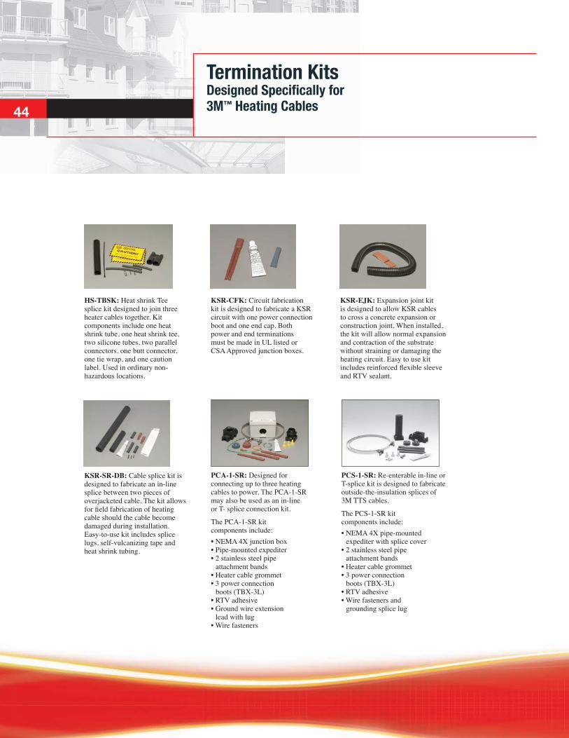
Termination KitsDesigned Specifically for 3M™ Heating Cables
PCA-1-SR: Designed for connecting up to three heating cables to power. The PCA-1-SR may also be used as an in-line or T- splice connection kit.
The PCA-1-SR kit components include: • NEMA 4X junction box • Pipe-mounted expediter • 2 stainless steel pipe attachment bands • Heater cable grommet • 3 power connection boots (TBX-3L) • RTV adhesive • Ground wire extension lead with lug • Wire fasteners
PCS-1-SR: Re-enterable in-line or T-splice kit is designed to fabricate outside-the-insulation splices of 3M TTS cables.
The PCS-1-SR kit components include: • NEMA 4X pipe-mounted expediter with splice cover • 2 stainless steel pipe attachment bands • Heater cable grommet • 3 power connection boots (TBX-3L) • RTV adhesive • Wire fasteners and grounding splice lug
HS-TBSK: Heat shrink Tee splice kit designed to join three heater cables together. Kit components include one heat shrink tube, one heat shrink tee, two silicone tubes, two parallel connectors, one butt connector, one tie wrap, and one caution label. Used in ordinary non-hazardous locations.
KSR-CFK: Circuit fabrication kit is designed to fabricate a KSR circuit with one power connection boot and one end cap. Both power and end terminations must be made in UL listed or CSA Approved junction boxes.
KSR-EJK: Expansion joint kit is designed to allow KSR cables to cross a concrete expansion or construction joint. When installed, the kit will allow normal expansion and contraction of the substrate without straining or damaging the heating circuit. Easy to use kit includes reinforced flexible sleeve and RTV sealant.
KSR-SR-DB: Cable splice kit is designed to fabricate an in-line splice between two pieces of overjacketed cable. The kit allows for field fabrication of heating cable should the cable become damaged during installation. Easy-to-use kit includes splice lugs, self-vulcanizing tape and heat shrink tubing.
44
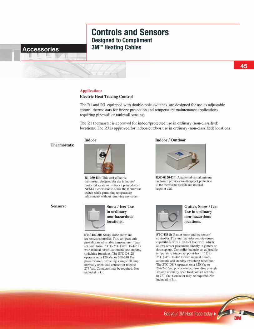
Controls and Sensors Designed to Compliment 3M™ Heating CablesAccessories
Application: Electric Heat Tracing Control
The R1 and R3, equipped with double-pole switches, are designed for use as adjustable control thermostats for freeze protection and temperature maintenance applications requiring pipewall or tankwall sensing.
The R1 thermostat is approved for indoor/protected use in ordinary (non-classified) locations. The R3 is approved for indoor/outdoor use in ordinary (non-classified) locations.
STC-DS-2B: Stand-alone snow and ice sensor/controller. This compact unit provides an adjustable temperature trigger set point from 1° C to 7° C (34° F to 44° F) with manual on/off, automatic and standby switching functions. The STC-DS-2B operates on a 120 Vac or 208-240 Vac power source, providing a single 30 amp normally open load contact set rated to 277 Vac. Contactor may be required. Not included in kit.
STC-DS-8: G utter snow and ice sensor/controller. This unit includes remote sensor capabilities with a 10-foot lead wire, which allows sensor placement directly in gutters or downspouts. Controller includes an adjustable temperature trigger set point from 1° C to 7° C (34° F to 44° F) with manual on/off, automatic and standby switching functions. The STC-DS-8 operates on a 120 Vac or 208-240 Vac power source, providing a single 30 amp normally open load contact set rated to 277 Vac. Contactor may be required. Not included in kit.
R1-050-DP: This cost-effective thermostat, designed for use in indoor/protected locations, utilizes a painted steel NEMA 1 enclosure to house the thermostat switch while permitting temperature adjustments without removing any cover.
R3C-0120-DP: A gasketed cast aluminum enclosure provides weatherproof protection to the thermostat switch and internal setpoint dial.
Thermostats:
Sensors:
Indoor Indoor / Outdoor
Snow / Ice: Use in ordinary non-hazardous locations.
Gutter, Snow / Ice: Use in ordinary non-hazardous locations.
45

Controls and Sensors Designed to Compliment 3M™ Heating Cables
Ratings/Specifications for R1 / R3:Voltage rating ................................................................................................ 240 VacSwitch rating .................................................................................................25 ampsSwitch type ........................................................................................................DPSTElectrical connection R11 ..............................................................................screw terminals on switch R32 ................................................................................................ 12 AWG leadsAdjustable control range R1 ....................................................................... 0° C to 50° C (32° F to 122° F) R3 ..................................................................... 0° C to 120° C (32° F to 248° F)Maximum control differential R1 ...................................................................................................1.8° C (32° F) R3 ..................................................................................................4.3° C (7.7° F)Setpoint repeatability R1 ............................................................................................... ±0.4° C (0.7° F) R3 ............................................................................................... ±1.1° C (2.0° F)Maximum bulb exposure temperature R1 ..................................................................................................68° C (154° F) R3 ................................................................................................200° C (392° F)Bulb dimensions R1 .................................................................................. 6 x 300 mm (1/4" x 12") R3 ..............................................................................6 x 140 mm (1/4" x 5-1/2")Bulb material ....................................................................................................copperCapillary length ...................................................................................... 300 cm (10')Capillary material .............................................................................................copper
Notes:1. The R1 includes two ½" or ¾" conduit knockouts with an internal grounding terminal.2. The R3 includes two ½" NPT conduit hubs with an internal grounding terminal.
Typical Wiring Diagram:
L1L2/N
R1-050-DP
Sensor
Heating Cable
57
R3C-0120-DP
46

CL: Caution labels are vinyl-based peel and stick with black letters on a yellow background and are intended for direct exposure to harsh environments. In accordance with the CEC (62-316), electrically heated pipelines and vessels are to be “suitably marked.”
Caution labels should be placed at 3 m (10') intervals or as required by code or specification (25 labels per pack).
Installation Accessories Designed to Compliment 3M™ Heating CablesAccessories
B-9, B-21: Stainless steel attachment bands for securing Thermon metallic and nonmetallic power connection and splice kits to pipes. Each kit includes two B-9 bands.
B-9: For pipes up to 203 mm (8") diameter
B-21: For pipes up to 530 mm (21") diameter
AL TAPE: Aluminum tape for securing cable in the bottom of a gutter or on a non-metallic pipe. Tape is designed to hold cable in place and prevent movement. Allow one foot of tape for each foot of heating cable. Tape is 51 mm (2") wide x 55 m (180') long.
BTape: Fibreglass cloth tape for circumferential banding cable to piping every 30 cm (12") or as required by code or specification. Tape is 13 mm (1/2") wide x 55 m (180') long. Max. Exposure Temp 150° C (300° F) Min. Installation Temp 0° C (32° F) Min. Operating Temp -40° C (-40° F)
47
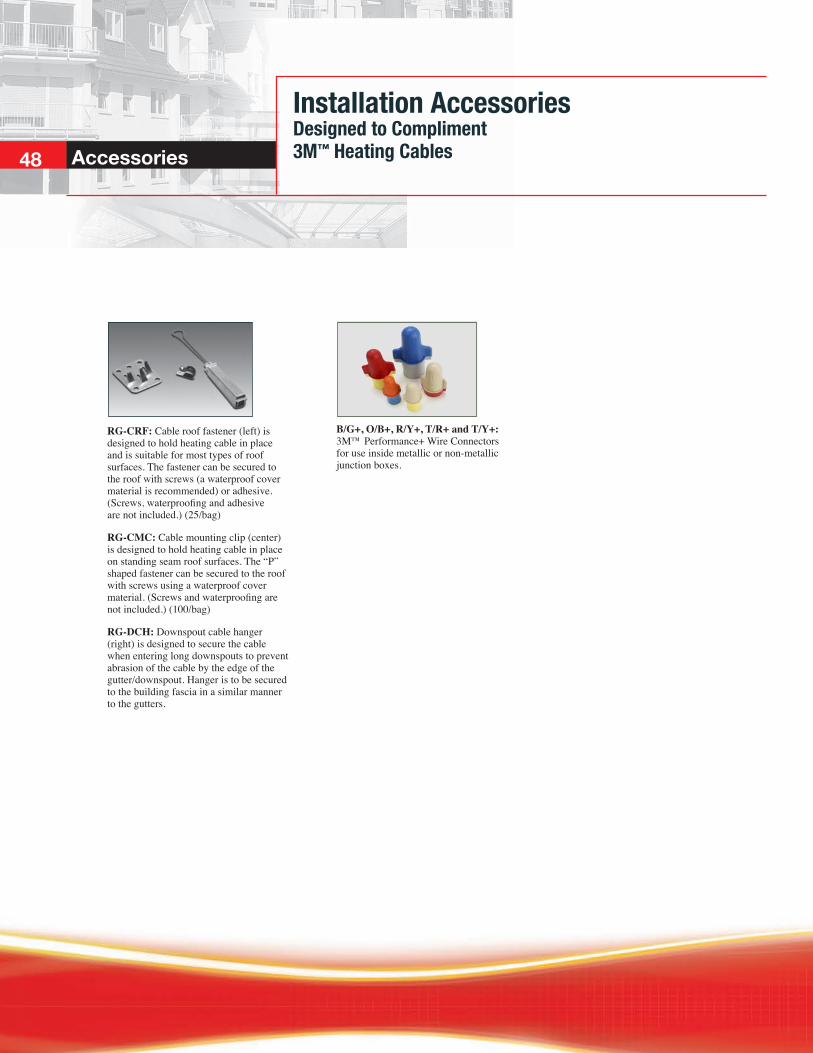
RG-CRF: Cable roof fastener (left) is designed to hold heating cable in place and is suitable for most types of roof surfaces. The fastener can be secured to the roof with screws (a waterproof cover material is recommended) or adhesive. (Screws, waterproofing and adhesive are not included.) (25/bag)
RG-CMC: Cable mounting clip (center) is designed to hold heating cable in place on standing seam roof surfaces. The “P” shaped fastener can be secured to the roof with screws using a waterproof cover material. (Screws and waterproofing are not included.) (100/bag)
RG-DCH: Downspout cable hanger (right) is designed to secure the cable when entering long downspouts to prevent abrasion of the cable by the edge of the gutter/downspout. Hanger is to be secured to the building fascia in a similar manner to the gutters.
B/G+, O/B+, R/Y+, T/R+ and T/Y+: 3M™ Performance+ Wire Connectors for use inside metallic or non-metallic junction boxes.
Installation Accessories Designed to Compliment 3M™ Heating CablesAccessories 48

Accessories
PLEASE NOTE: The diagrams and instructions outlined in this guide are for illustration purposes only. They are not necessarily to scale and do not necessarily represent exact real-world heat tracing systems. In addition, they are not meant or implied to be a replacement for a licensed professional. Any use of 3M Heat Tracing Cables must be in accordance with all local regulations and/or building codes. Please consult your local authority.

Related Documents