3GPP TS 25.213 V3.9.0 (2003-12) Technical Specification 3rd Generation Partnership Project; Technical Specification Group Radio Access Network; Spreading and modulation (FDD) (Release 1999) The present document has been developed within the 3 rd Generation Partnership Project (3GPP TM ) and may be further elaborated for the purposes of 3GPP. The present document has not been subject to any approval process by the 3GPP Organisational Partners and shall not be implemented. This Specification is provided for future development work within 3GPP only. The Organisational Partners accept no liability for any use of this Specification. Specifications and reports for implementation of the 3GPP TM system should be obtained via the 3GPP Organisational Partners' Publications Offices.

Welcome message from author
This document is posted to help you gain knowledge. Please leave a comment to let me know what you think about it! Share it to your friends and learn new things together.
Transcript

3GPP TS 25.213 V3.9.0 (2003-12)Technical Specification
3rd Generation Partnership Project;Technical Specification Group Radio Access Network;
Spreading and modulation (FDD)(Release 1999)
The present document has been developed within the 3rd Generation Partnership Project (3GPP TM) and may be further elaborated for the purposes of 3GPP. The present document has not been subject to any approval process by the 3GPP Organisational Partners and shall not be implemented. This Specification is provided for future development work within 3GPP only. The Organisational Partners accept no liability for any use of this Specification.Specifications and reports for implementation of the 3GPP TM system should be obtained via the 3GPP Organisational Partners' Publications Offices.

3GPP
3GPP TS 25.213 V3.9.0 (2003-12)2Release 1999
Keywords UMTS, radio, modulation, layer 1
3GPP
Postal address
3GPP support office address 650 Route des Lucioles - Sophia Antipolis
Valbonne - FRANCE Tel.: +33 4 92 94 42 00 Fax: +33 4 93 65 47 16
Internet http://www.3gpp.org
Copyright Notification
No part may be reproduced except as authorized by written permission. The copyright and the foregoing restriction extend to reproduction in all media.
© 2004, 3GPP Organizational Partners (ARIB, CCSA, ETSI, T1, TTA, TTC).
All rights reserved.
3GPP
3GPP TS 25.213 V3.9.0 (2003-12)3Release 1999
Contents Foreword.............................................................................................................................................................6 1 Scope ........................................................................................................................................................7 2 References ................................................................................................................................................7 3 Symbols and abbreviations.......................................................................................................................7 3.1 Symbols ................................................................................................................................................................... 7 3.2 Abbreviations .......................................................................................................................................................... 7 4 Uplink spreading and modulation ............................................................................................................8 4.1 Overview ................................................................................................................................................................. 8 4.2 Spreading................................................................................................................................................................. 8 4.2.1 DPCCH/DPDCH ............................................................................................................................................... 8 4.2.2 PRACH............................................................................................................................................................ 10 4.2.2.1 PRACH preamble part ..................................................................................................................................... 10 4.2.2.2 PRACH message part ...................................................................................................................................... 10 4.2.3 PCPCH............................................................................................................................................................. 10 4.2.3.1 PCPCH preamble part...................................................................................................................................... 10 4.2.3.2 PCPCH message part ....................................................................................................................................... 10 4.3 Code generation and allocation ............................................................................................................................. 11 4.3.1 Channelization codes ....................................................................................................................................... 11 4.3.1.1 Code definition ................................................................................................................................................ 11 4.3.1.2 Code allocation for DPCCH/DPDCH.............................................................................................................. 12 4.3.1.3 Code allocation for PRACH message part....................................................................................................... 12 4.3.1.4 Code allocation for PCPCH message part ....................................................................................................... 12 4.3.1.5 Channelisation code for PCPCH power control preamble............................................................................ 13 4.3.2 Scrambling codes............................................................................................................................................. 13 4.3.2.1 General............................................................................................................................................................. 13 4.3.2.2 Long scrambling sequence............................................................................................................................... 13 4.3.2.3 Short scrambling sequence .............................................................................................................................. 14 4.3.2.4 DPCCH/DPDCH scrambling code .................................................................................................................. 15 4.3.2.5 PRACH message part scrambling code ........................................................................................................... 15 4.3.2.6 PCPCH message part scrambling code............................................................................................................ 16 4.3.2.7 PCPCH power control preamble scrambling code........................................................................................... 16 4.3.3 PRACH preamble codes .................................................................................................................................. 16 4.3.3.1 Preamble code construction ............................................................................................................................. 16 4.3.3.2 Preamble scrambling code ............................................................................................................................... 16 4.3.3.3 Preamble signature........................................................................................................................................... 17 4.3.4 PCPCH preamble codes................................................................................................................................... 17 4.3.4.1 Access preamble .............................................................................................................................................. 17 4.3.4.1.1 Access preamble code construction ........................................................................................................... 17 4.3.4.1.2 Access preamble scrambling code ............................................................................................................. 17 4.3.4.1.3 Access preamble signature ......................................................................................................................... 18 4.3.4.2 CD preamble.................................................................................................................................................... 18 4.3.4.2.1 CD preamble code construction ................................................................................................................. 18 4.3.4.2.2 CD preamble scrambling code ................................................................................................................... 18 4.3.4.2.3 CD preamble signature............................................................................................................................... 18 4.4 Modulation ............................................................................................................................................................ 19 4.4.1 Modulating chip rate........................................................................................................................................ 19 4.4.2 Modulation....................................................................................................................................................... 19 5 Downlink spreading and modulation .....................................................................................................19 5.1 Spreading............................................................................................................................................................... 19 5.2 Code generation and allocation ............................................................................................................................. 20 5.2.1 Channelization codes ....................................................................................................................................... 20 5.2.2 Scrambling code .............................................................................................................................................. 21 5.2.3 Synchronisation codes ..................................................................................................................................... 22 5.2.3.1 Code generation ............................................................................................................................................... 22

3GPP
3GPP TS 25.213 V3.9.0 (2003-12)4Release 1999
5.2.3.2 Code allocation of SSC.................................................................................................................................... 23 5.3 Modulation ............................................................................................................................................................ 25 5.3.1 Modulating chip rate........................................................................................................................................ 25 5.3.2 Modulation....................................................................................................................................................... 25
Annex A (informative): Generalised Hierarchical Golay Sequences.................................................26 A.1 Alternative generation ............................................................................................................................26
Annex B (informative): Change history ...............................................................................................27
3GPP
3GPP TS 25.213 V3.9.0 (2003-12)5Release 1999
Foreword This Technical Specification (TS) has been produced by the 3rd Generation Partnership Project (3GPP).
The contents of the present document are subject to continuing work within the TSG and may change following formal TSG approval. Should the TSG modify the contents of the present document, it will be re-released by the TSG with an identifying change of release date and an increase in version number as follows:
Version x.y.z
where:
x the first digit:
1 presented to TSG for information;
2 presented to TSG for approval;
3 or greater indicates TSG approved document under change control.
y the second digit is incremented for all changes of substance, i.e. technical enhancements, corrections, updates, etc.
z the third digit is incremented when editorial only changes have been incorporated in the document.
3GPP
3GPP TS 25.213 V3.9.0 (2003-12)6Release 1999
1 Scope The present document describes spreading and modulation for UTRA Physical Layer FDD mode.
2 References The following documents contain provisions which, through reference in this text, constitute provisions of the present document.
• References are either specific (identified by date of publication, edition number, version number, etc.) or non-specific.
• For a specific reference, subsequent revisions do not apply.
• For a non-specific reference, the latest version applies. In the case of a reference to a 3GPP document (including a GSM document), a non-specific reference implicitly refers to the latest version of that document in the same Release as the present document.
[1] 3G TS 25.201: "Physical layer - general description".
[2] 3G TS 25.211: "Physical channels and mapping of transport channels onto physical channels (FDD)."
[3] 3G TS 25.101: "UE Radio transmission and Reception (FDD)".
[4] 3G TS 25.104: "UTRA (BS) FDD; Radio transmission and Reception".
3 Symbols and abbreviations
3.1 Symbols For the purposes of the present document, the following symbols apply:
Cch,SF,n: n:th channelisation code with spreading factor SF Cpre,n,s: PRACH preamble code for n:th preamble scrambling code and signature s Cc-acc,n,s: PCPCH access preamble code for n:th preamble scrambling code and signature s Cc-cd,n,s: PCPCH CD preamble code for n:th preamble scrambling code and signature s Csig,s: PRACH/PCPCH signature code for signature s Sdpch,n: n:th DPCCH/DPDCH uplink scrambling code Sr-pre,n: n:th PRACH preamble scrambling code Sr-msg,n: n:th PRACH message scrambling code Sc-acc: n:th PCPCH access preamble scrambling code Sc-cd: n:th PCPCH CD preamble scrambling code Sc-msg,n: n:th PCPCH message scrambling code Sdl,n: DL scrambling code Cpsc: PSC code Cssc,n: n:th SSC code
3.2 Abbreviations For the purposes of the present document, the following abbreviations apply:
AICH Acquisition Indicator Channel AP Access Preamble
3GPP
3GPP TS 25.213 V3.9.0 (2003-12)7Release 1999
BCH Broadcast Control Channel CCPCH Common Control Physical Channel CD Collision Detection CPCH Common Packet Channel CPICH Common Pilot Channel DCH Dedicated Channel DPCH Dedicated Physical Channel DPCCH Dedicated Physical Control Channel DPDCH Dedicated Physical Data Channel FDD Frequency Division Duplex Mcps Mega Chip Per Second OVSF Orthogonal Variable Spreading Factor (codes) PDSCH Physical Dedicated Shared Channel PICH Page Indication Channel PRACH Physical Random Access Channel PSC Primary Synchronisation Code RACH Random Access Channel SCH Synchronisation Channel SSC Secondary Synchronisation Code SF Spreading Factor UE User Equipment
4 Uplink spreading and modulation
4.1 Overview Spreading is applied to the physical channels. It consists of two operations. The first is the channelization operation, which transforms every data symbol into a number of chips, thus increasing the bandwidth of the signal. The number of chips per data symbol is called the Spreading Factor (SF). The second operation is the scrambling operation, where a scrambling code is applied to the spread signal.
With the channelization, data symbols on so-called I- and Q-branches are independently multiplied with an OVSF code. With the scrambling operation, the resultant signals on the I- and Q-branches are further multiplied by complex-valued scrambling code, where I and Q denote real and imaginary parts, respectively.
4.2 Spreading
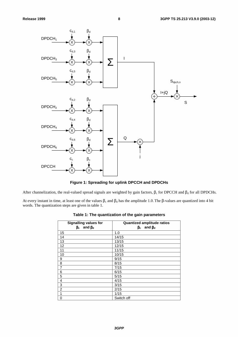
4.2.1 DPCCH/DPDCH Figure 1 illustrates the principle of the uplink spreading of DPCCH and DPDCHs. The binary DPCCH and DPDCHs to be spread are represented by real-valued sequences, i.e. the binary value "0" is mapped to the real value +1, while the binary value "1" is mapped to the real value –1. The DPCCH is spread to the chip rate by the channelization code cc, while the n:th DPDCH called DPDCHn is spread to the chip rate by the channelization code cd,n. One DPCCH and up to six parallel DPDCHs can be transmitted simultaneously, i.e. 1 ≤ n ≤ 6.
3GPP
3GPP TS 25.213 V3.9.0 (2003-12)8Release 1999
IΣ
j
cd,1 βd
Sdpch,n
I+jQ
DPDCH1
Q
cd,3 βd
DPDCH3
cd,5 βd
DPDCH5
cd,2 βd
DPDCH2
cd,4 βd
DPDCH4
cd,6 βd
DPDCH6
cc βc
DPCCH
Σ
S
Figure 1: Spreading for uplink DPCCH and DPDCHs
After channelization, the real-valued spread signals are weighted by gain factors, βc for DPCCH and βd for all DPDCHs.
At every instant in time, at least one of the values βc and βd has the amplitude 1.0. The β-values are quantized into 4 bit words. The quantization steps are given in table 1.
Table 1: The quantization of the gain parameters
Signalling values for ββββc and ββββd
Quantized amplitude ratios ββββc and ββββd
15 1.0 14 14/15 13 13/15 12 12/15 11 11/15 10 10/15 9 9/15 8 8/15 7 7/15 6 6/15 5 5/15 4 4/15 3 3/15 2 2/15 1 1/15 0 Switch off

3GPP
3GPP TS 25.213 V3.9.0 (2003-12)9Release 1999
After the weighting, the stream of real-valued chips on the I- and Q-branches are then summed and treated as a complex-valued stream of chips. This complex-valued signal is then scrambled by the complex-valued scrambling code Sdpch,n. The scrambling code is applied aligned with the radio frames, i.e. the first scrambling chip corresponds to the beginning of a radio frame.
4.2.2 PRACH
4.2.2.1 PRACH preamble part
The PRACH preamble part consists of a complex-valued code, described in section 4.3.3.
4.2.2.2 PRACH message part
Figure 2 illustrates the principle of the spreading and scrambling of the PRACH message part, consisting of data and control parts. The binary control and data parts to be spread are represented by real-valued sequences, i.e. the binary value "0" is mapped to the real value +1, while the binary value "1" is mapped to the real value –1. The control part is spread to the chip rate by the channelization code cc, while the data part is spread to the chip rate by the channelization code cd.
jβccc
cd βd
Sr-msg,n
I+jQ
PRACH messagecontrol part
PRACH messagedata part
Q
I
S
Figure 2: Spreading of PRACH message part
After channelization, the real-valued spread signals are weighted by gain factors, βc for the control part and βd for the data part. At every instant in time, at least one of the values βc and βd has the amplitude 1.0. The β-values are quantized into 4 bit words. The quantization steps are given in section 4.2.1.
After the weighting, the stream of real-valued chips on the I- and Q-branches are treated as a complex-valued stream of chips. This complex-valued signal is then scrambled by the complex-valued scrambling code Sr-msg,n. The 10 ms scrambling code is applied aligned with the 10 ms message part radio frames, i.e. the first scrambling chip corresponds to the beginning of a message part radio frame.
4.2.3 PCPCH
4.2.3.1 PCPCH preamble part
The PCPCH preamble part consists of a complex-valued code, described in section 4.3.4.
4.2.3.2 PCPCH message part
Figure 3 illustrates the principle of the spreading of the PCPCH message part, consisting of data and control parts. The binary control and data parts to be spread are represented by real-valued sequences, i.e. the binary value "0" is mapped to the real value +1, while the binary value "1" is mapped to the real value –1. The control part is spread to the chip rate by the channelization code cc, while the data part is spread to the chip rate by the channelization code cd.

3GPP
3GPP TS 25.213 V3.9.0 (2003-12)10Release 1999
jβccc
cd βd
Sc-msg,n
I+jQ
PCPCH messagecontrol part
PCPCH messagedata part
Q
I
S
Figure 3: Spreading of PCPCH message part
After channelization, the real-valued spread signals are weighted by gain factors, βc for the control part and βd for the data part. At every instant in time, at least one of the values βc and βd has the amplitude 1.0. The β-values are quantized into 4 bit words. The quantization steps are given in section 4.2.1.
After the weighting, the stream of real-valued chips on the I- and Q-branches are treated as a complex-valued stream of chips. This complex-valued signal is then scrambled by the complex-valued scrambling code Sc-msg,n. The 10 ms scrambling code is applied aligned with the 10 ms message part radio frames, i.e. the first scrambling chip corresponds to the beginning of a message part radio frame.
4.3 Code generation and allocation
4.3.1 Channelization codes
4.3.1.1 Code definition
The channelization codes of figure 1 are Orthogonal Variable Spreading Factor (OVSF) codes that preserve the orthogonality between a user’s different physical channels. The OVSF codes can be defined using the code tree of figure 4.
SF = 1 SF = 2 SF = 4
C ch,1 ,0 = (1 )
C ch,2,0 = (1 ,1 )
C ch,2,1 = (1 ,-1 )
C ch,4,0 = (1 ,1 ,1 ,1 )
C ch,4,1 = (1 ,1 ,-1 ,-1)
C ch,4,2 = (1 ,-1 ,1 ,-1)
C ch,4,3 = (1 ,-1 ,-1 ,1)
Figure 4: Code-tree for generation of Orthogonal Variable Spreading Factor (OVSF) codes
In figure 4, the channelization codes are uniquely described as Cch,SF,k, where SF is the spreading factor of the code and k is the code number, 0 ≤ k ≤ SF-1.

3GPP
3GPP TS 25.213 V3.9.0 (2003-12)11Release 1999
Each level in the code tree defines channelization codes of length SF, corresponding to a spreading factor of SF in figure 4.
The generation method for the channelization code is defined as:
1Cch,1,0 = ,
−
=
−
=
1111
0,1,
0,1,
0,1,
0,1,
1,2,
0,2,
ch
ch
ch
ch
ch
ch
CC
CC
CC
( )
( )
( )
( )
( ) ( )
( ) ( )
−
−
−
=
−−
−−
−++
−++
+
+
+
+
12,2,12,2,
12,2,12,2,
1,2,1,2,
1,2,1,2,
0,2,0,2,
0,2,0,2,
112,12,
212,12,
3,12,
2,12,
1,12,
0,12,
:::
nnchnnch
nnchnnch
nchnch
nchnch
nchnch
nchnch
nnch
nnch
nch
nch
nch
nch
CCCC
CCCCCC
CC
CC
CCCC
The leftmost value in each channelization code word corresponds to the chip transmitted first in time.
4.3.1.2 Code allocation for DPCCH/DPDCH
For the DPCCH and DPDCHs the following applies:
- The DPCCH is always spread by code cc = Cch,256,0.
- When only one DPDCH is to be transmitted, DPDCH1 is spread by code cd,1 = Cch,SF,k where SF is the spreading factor of DPDCH1 and k= SF / 4.
- When more than one DPDCH is to be transmitted, all DPDCHs have spreading factors equal to 4. DPDCHn is spread by the the code cd,n = Cch,4,k , where k = 1 if n ∈ {1, 2}, k = 3 if n ∈ {3, 4}, and k = 2 if n ∈ {5, 6}.
If a power control preamble is used to initialise a DCH, the channelisation code for the DPCCH during the power control preamble shall be the same as that to be used afterwards.
4.3.1.3 Code allocation for PRACH message part
The preamble signature s, 0 ≤ s ≤ 15, points to one of the 16 nodes in the code-tree that corresponds to channelization codes of length 16. The sub-tree below the specified node is used for spreading of the message part. The control part is spread with the channelization code cc (as shown in section 4.2.2.2) of spreading factor 256 in the lowest branch of the sub-tree, i.e. cc = Cch,256,m where m = 16×s + 15. The data part uses any of the channelization codes from spreading factor 32 to 256 in the upper-most branch of the sub-tree. To be exact, the data part is spread by channelization code cd = Cch,SF,m and SF is the spreading factor used for the data part and m = SF×s/16.
4.3.1.4 Code allocation for PCPCH message part
For the control part and data part the following applies:
- The control part is always spread by code cc=Cch,256,0.
- The data part is spread by code cd=Cch,SF,k where SF is the spreading factor of the data part and k=SF/4.
The data part may use the code from spreading factor 4 to 256. A UE is allowed to increase SF during the message transmission on a frame by frame basis.

3GPP
3GPP TS 25.213 V3.9.0 (2003-12)12Release 1999
4.3.1.5 Channelisation code for PCPCH power control preamble
The channelisation code for the PCPCH power control preamble is the same as that used for the control part of the message part, as described in section 4.3.1.4 above.
4.3.2 Scrambling codes
4.3.2.1 General
All uplink physical channels are subjected to scrambling with a complex-valued scrambling code. The DPCCH/DPDCH may be scrambled by either long or short scrambling codes, defined in section 4.3.2.4. The PRACH message part is scrambled with a long scrambling code, defined in section 4.3.2.5. Also the PCPCH message part is scrambled with a long scrambling code, defined in section 4.3.2.6.
There are 224 long and 224 short uplink scrambling codes. Uplink scrambling codes are assigned by higher layers.
The long scrambling code is built from constituent long sequences defined in section 4.3.2.2, while the constituent short sequences used to build the short scrambling code are defined in section 4.3.2.3.
4.3.2.2 Long scrambling sequence
The long scrambling sequences clong,1,n and clong,2,n are constructed from position wise modulo 2 sum of 38400 chip segments of two binary m-sequences generated by means of two generator polynomials of degree 25. Let x, and y be the two m-sequences respectively. The x sequence is constructed using the primitive (over GF(2)) polynomial X25+X3+1. The y sequence is constructed using the polynomial X25+X3+X2+X+1. The resulting sequences thus constitute segments of a set of Gold sequences.
The sequence clong,2,n is a 16777232 chip shifted version of the sequence clong,1,n.
Let n23 … n0 be the 24 bit binary representation of the scrambling sequence number n with n0 being the least significant bit. The x sequence depends on the chosen scrambling sequence number n and is denoted xn, in the sequel. Furthermore, let xn(i) and y(i) denote the i:th symbol of the sequence xn and y, respectively.
The m-sequences xn and y are constructed as:
Initial conditions:
- xn(0)=n0 , xn(1)= n1 , … =xn(22)= n22 ,xn(23)= n23, xn(24)=1.
- y(0)=y(1)= … =y(23)= y(24)=1.
Recursive definition of subsequent symbols:
- xn(i+25) =xn(i+3) + xn(i) modulo 2, i=0,…, 225-27.
- y(i+25) = y(i+3)+y(i+2) +y(i+1) +y(i) modulo 2, i=0,…, 225-27.
Define the binary Gold sequence zn by:
- zn(i) = xn(i) + y(i) modulo 2, i = 0, 1, 2, …, 225-2.
The real valued Gold sequence Zn is defined by:
.22,,1,01)(10)(1
)( 25 −=
=−=+
= Kiforizifizif
iZn
nn
Now, the real-valued long scrambling sequences clong,1,n and clong,2,n are defined as follows:
clong,1,n(i) = Zn(i), i = 0, 1, 2, …, 225 – 2 and
clong,2,n(i) = Zn((i + 16777232) modulo (225 – 1)), i = 0, 1, 2, …, 225 – 2.
Finally, the complex-valued long scrambling sequence Clong, n, is defined as:
3GPP
3GPP TS 25.213 V3.9.0 (2003-12)13Release 1999
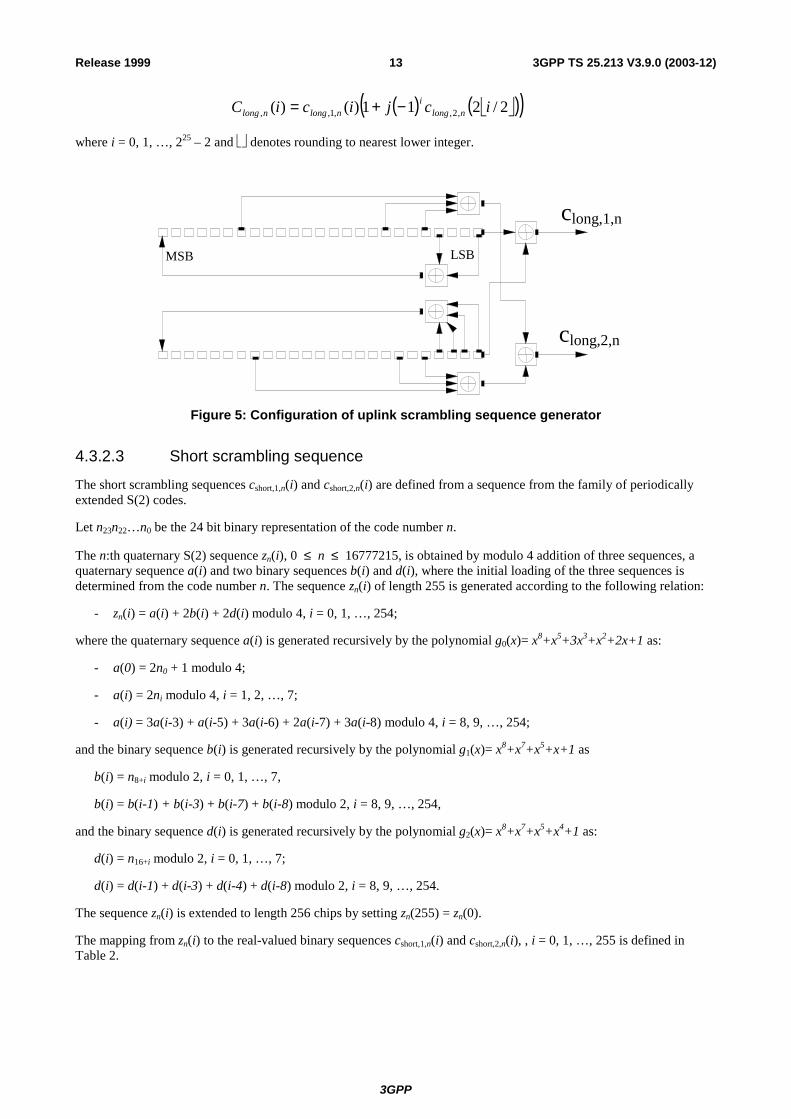
( ) ( )( )2/211)()( ,2,,1,, icjiciC nlongi
nlongnlong −+=
where i = 0, 1, …, 225 – 2 and denotes rounding to nearest lower integer.
clong,1,n
clong,2,n
MSB LSB
Figure 5: Configuration of uplink scrambling sequence generator
4.3.2.3 Short scrambling sequence
The short scrambling sequences cshort,1,n(i) and cshort,2,n(i) are defined from a sequence from the family of periodically extended S(2) codes.
Let n23n22…n0 be the 24 bit binary representation of the code number n.
The n:th quaternary S(2) sequence zn(i), 0 ≤ n ≤ 16777215, is obtained by modulo 4 addition of three sequences, a quaternary sequence a(i) and two binary sequences b(i) and d(i), where the initial loading of the three sequences is determined from the code number n. The sequence zn(i) of length 255 is generated according to the following relation:
- zn(i) = a(i) + 2b(i) + 2d(i) modulo 4, i = 0, 1, …, 254;
where the quaternary sequence a(i) is generated recursively by the polynomial g0(x)= x8+x5+3x3+x2+2x+1 as:
- a(0) = 2n0 + 1 modulo 4;
- a(i) = 2ni modulo 4, i = 1, 2, …, 7;
- a(i) = 3a(i-3) + a(i-5) + 3a(i-6) + 2a(i-7) + 3a(i-8) modulo 4, i = 8, 9, …, 254;
and the binary sequence b(i) is generated recursively by the polynomial g1(x)= x8+x7+x5+x+1 as
b(i) = n8+i modulo 2, i = 0, 1, …, 7,
b(i) = b(i-1) + b(i-3) + b(i-7) + b(i-8) modulo 2, i = 8, 9, …, 254,
and the binary sequence d(i) is generated recursively by the polynomial g2(x)= x8+x7+x5+x4+1 as:
d(i) = n16+i modulo 2, i = 0, 1, …, 7;
d(i) = d(i-1) + d(i-3) + d(i-4) + d(i-8) modulo 2, i = 8, 9, …, 254.
The sequence zn(i) is extended to length 256 chips by setting zn(255) = zn(0).
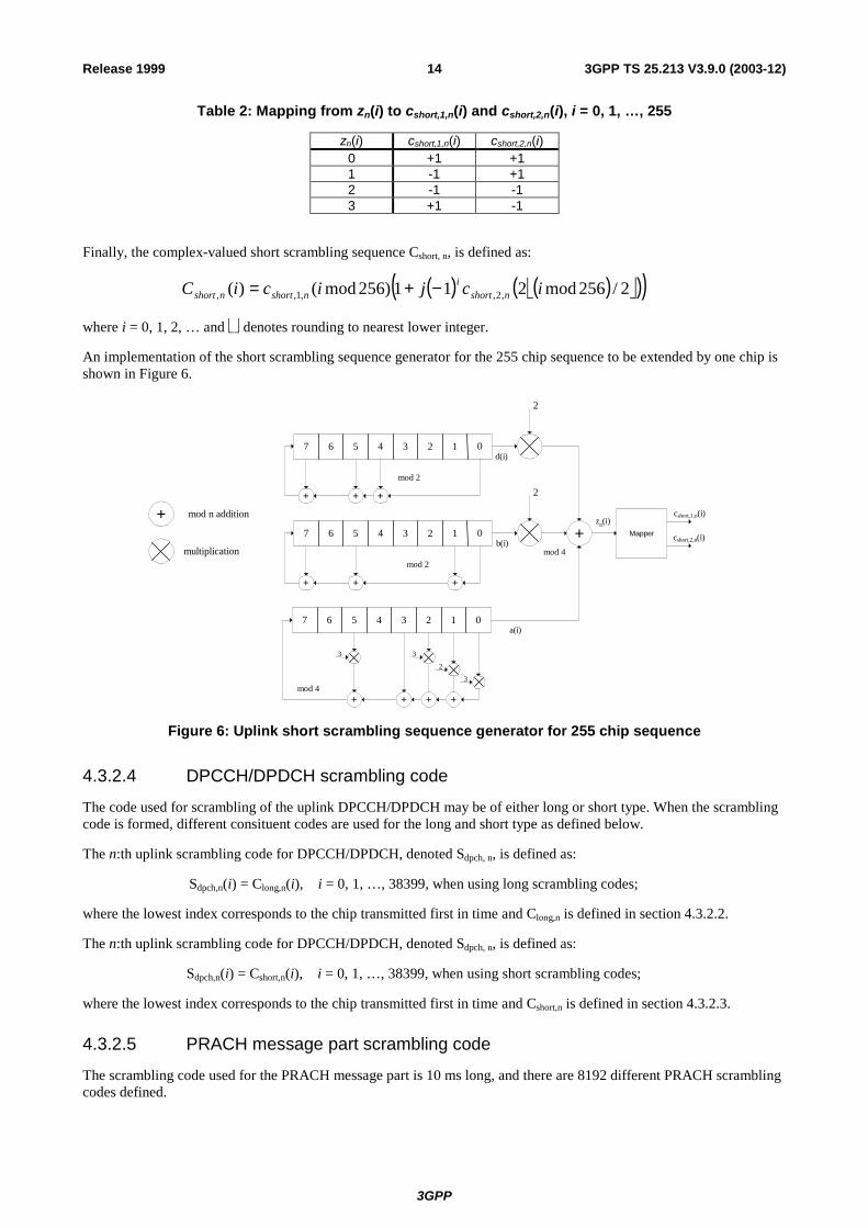
The mapping from zn(i) to the real-valued binary sequences cshort,1,n(i) and cshort,2,n(i), , i = 0, 1, …, 255 is defined in Table 2.
3GPP
3GPP TS 25.213 V3.9.0 (2003-12)14Release 1999
Table 2: Mapping from zn(i) to cshort,1,n(i) and cshort,2,n(i), i = 0, 1, …, 255
zn(i) cshort,1,n(i) cshort,2,n(i) 0 +1 +1 1 -1 +1 2 -1 -1 3 +1 -1
Finally, the complex-valued short scrambling sequence Cshort, n, is defined as:
( ) ( ) ( )( )2/256mod211)256mod()( ,2,,1,, icjiciC nshorti
nshortnshort −+=
where i = 0, 1, 2, … and denotes rounding to nearest lower integer.
An implementation of the short scrambling sequence generator for the 255 chip sequence to be extended by one chip is shown in Figure 6.
07 4
+ mod n addition
d(i)12356
2
mod 2
07 4b(i)
12356
2
mod 2
+mod 4multiplication
zn(i)
07 4 12356
+mod 4
Mapper
cshort,1,n(i)
a(i)
+ + +
+ ++
+ ++
3 3
3
2
cshort,2,n(i)
Figure 6: Uplink short scrambling sequence generator for 255 chip sequence
4.3.2.4 DPCCH/DPDCH scrambling code
The code used for scrambling of the uplink DPCCH/DPDCH may be of either long or short type. When the scrambling code is formed, different consituent codes are used for the long and short type as defined below.
The n:th uplink scrambling code for DPCCH/DPDCH, denoted Sdpch, n, is defined as:
Sdpch,n(i) = Clong,n(i), i = 0, 1, …, 38399, when using long scrambling codes;
where the lowest index corresponds to the chip transmitted first in time and Clong,n is defined in section 4.3.2.2.
The n:th uplink scrambling code for DPCCH/DPDCH, denoted Sdpch, n, is defined as:
Sdpch,n(i) = Cshort,n(i), i = 0, 1, …, 38399, when using short scrambling codes;
where the lowest index corresponds to the chip transmitted first in time and Cshort,n is defined in section 4.3.2.3.
4.3.2.5 PRACH message part scrambling code
The scrambling code used for the PRACH message part is 10 ms long, and there are 8192 different PRACH scrambling codes defined.

3GPP
3GPP TS 25.213 V3.9.0 (2003-12)15Release 1999
The n:th PRACH message part scrambling code, denoted Sr-msg,n, where n = 0, 1, …, 8191, is based on the long scrambling sequence and is defined as:
Sr-msg,n(i) = Clong,n(i + 4096), i = 0, 1, …, 38399
where the lowest index corresponds to the chip transmitted first in time and Clong,n is defined in section 4.3.2.2.
The message part scrambling code has a one-to-one correspondence to the scrambling code used for the preamble part. For one PRACH, the same code number is used for both scrambling codes, i.e. if the PRACH preamble scrambling code used is Sr-pre,m then the PRACH message part scrambling code is Sr-msg,m, where the number m is the same for both codes.
4.3.2.6 PCPCH message part scrambling code
The set of scrambling codes used for the PCPCH message part are 10 ms long, cell-specific, and each scrambling code has a one-to-one correspondence to the signature sequence and the access sub-channel used by the access preamble part. Both long or short scrambling codes can be used to scramble the CPCH message part. There are 64 uplink scrambling codes defined per cell and 32768 different PCPCH scrambling codes defined in the system.
The n:th PCPCH message part scrambling code, denoted Sc-msg,,n, where n =8192,8193, …,40959 is based on the scrambling sequence and is defined as:
In the case when the long scrambling codes are used:
Sc-msg,n(i) = Clong,n(i ), i = 0, 1, …, 38399
where the lowest index corresponds to the chip transmitted first in time and Clong,n is defined in section 4.3.2.2.
In the case the short scrambling codes are used:
Sc-msg,n(i) = Cshort,n(i), i = 0, 1, …, 38399
The 32768 PCPCH scrambling codes are divided into 512 groups with 64 codes in each group. There is a one-to-one correspondence between the group of PCPCH preamble scrambling codes in a cell and the primary scrambling code used in the downlink of the cell. The k:th PCPCH scrambling code within the cell with downlink primary scrambling code m, k =16,17,…, 79 and m = 0, 1, 2, …, 511, is Sc-msg, n as defined above with n = 64×m + k+8176.
4.3.2.7 PCPCH power control preamble scrambling code
The scrambling code for the PCPCH power control preamble is the same as for the PCPCH message part, as described in section 4.3.2.6 above. The phase of the scrambling code shall be such that the end of the code is aligned with the frame boundary at the end of the power control preamble.
4.3.3 PRACH preamble codes
4.3.3.1 Preamble code construction
The random access preamble code Cpre,n, is a complex valued sequence. It is built from a preamble scrambling code Sr-pre,n and a preamble signature Csig,s as follows:
- Cpre,n,s(k) = Sr-pre,n(k) × Csig,s(k) × )
24( kj
eπ+π
, k = 0, 1, 2, 3, …, 4095;
where k=0 corresponds to the chip transmitted first in time and Sr-pre,n and Csig,s are defined in 4.3.3.2 and 4.3.3.3 below respectively.
4.3.3.2 Preamble scrambling code
The scrambling code for the PRACH preamble part is constructed from the long scrambling sequences. There are 8192 PRACH preamble scrambling codes in total.
The n:th preamble scrambling code, n = 0, 1, …, 8191, is defined as:
3GPP
3GPP TS 25.213 V3.9.0 (2003-12)16Release 1999
Sr-pre,n(i) = clong,1,n(i), i = 0, 1, …, 4095;
where the sequence clong,1,n is defined in section 4.3.2.2.
The 8192 PRACH preamble scrambling codes are divided into 512 groups with 16 codes in each group. There is a one-to-one correspondence between the group of PRACH preamble scrambling codes in a cell and the primary scrambling code used in the downlink of the cell. The k:th PRACH preamble scrambling code within the cell with downlink primary scrambling code m, k = 0, 1, 2, …, 15 and m = 0, 1, 2, …, 511, is Sr-pre,n(i) as defined above with n = 16×m + k.
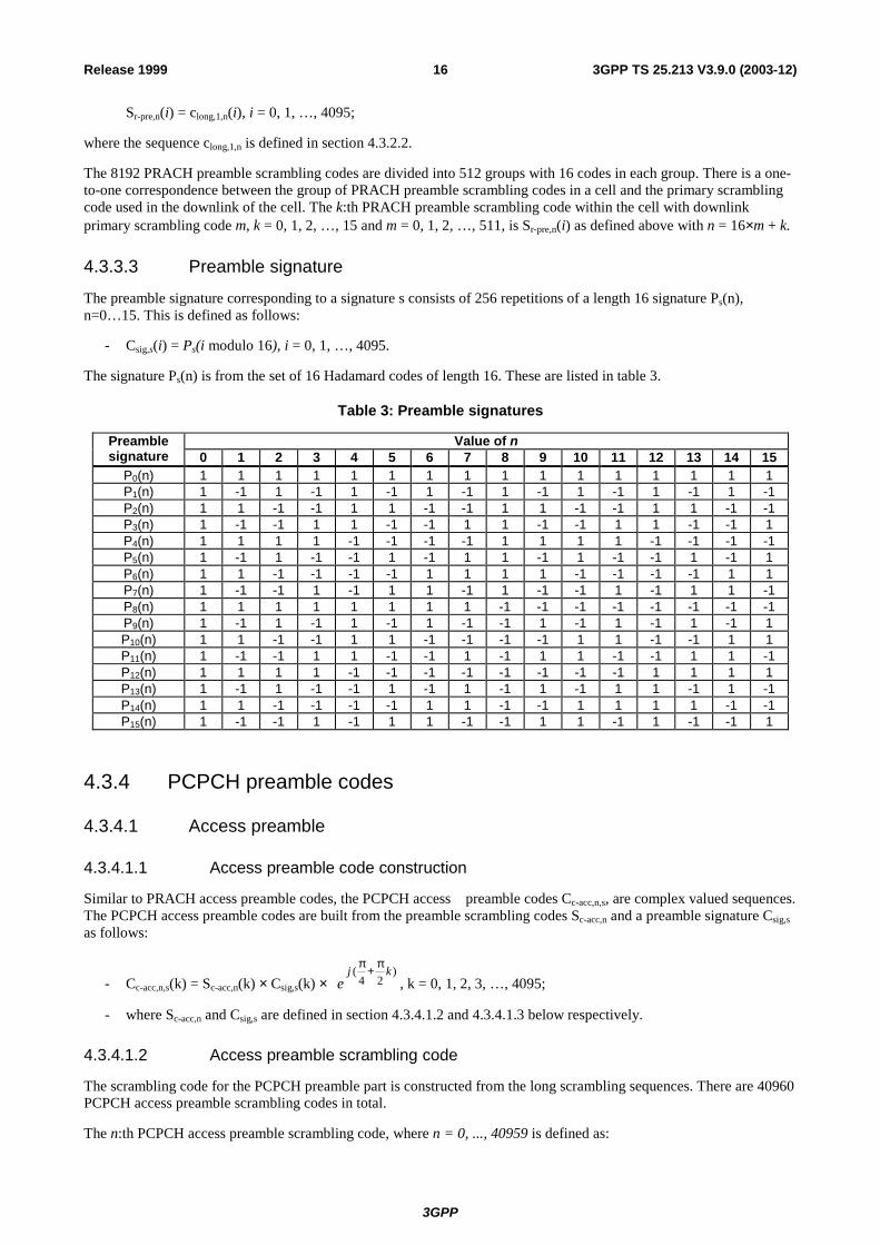
4.3.3.3 Preamble signature
The preamble signature corresponding to a signature s consists of 256 repetitions of a length 16 signature Ps(n), n=0…15. This is defined as follows:
- Csig,s(i) = Ps(i modulo 16), i = 0, 1, …, 4095.
The signature Ps(n) is from the set of 16 Hadamard codes of length 16. These are listed in table 3.
Table 3: Preamble signatures
Value of n Preamble signature 0 1 2 3 4 5 6 7 8 9 10 11 12 13 14 15
P0(n) 1 1 1 1 1 1 1 1 1 1 1 1 1 1 1 1 P1(n) 1 -1 1 -1 1 -1 1 -1 1 -1 1 -1 1 -1 1 -1P2(n) 1 1 -1 -1 1 1 -1 -1 1 1 -1 -1 1 1 -1 -1P3(n) 1 -1 -1 1 1 -1 -1 1 1 -1 -1 1 1 -1 -1 1 P4(n) 1 1 1 1 -1 -1 -1 -1 1 1 1 1 -1 -1 -1 -1P5(n) 1 -1 1 -1 -1 1 -1 1 1 -1 1 -1 -1 1 -1 1 P6(n) 1 1 -1 -1 -1 -1 1 1 1 1 -1 -1 -1 -1 1 1 P7(n) 1 -1 -1 1 -1 1 1 -1 1 -1 -1 1 -1 1 1 -1P8(n) 1 1 1 1 1 1 1 1 -1 -1 -1 -1 -1 -1 -1 -1P9(n) 1 -1 1 -1 1 -1 1 -1 -1 1 -1 1 -1 1 -1 1 P10(n) 1 1 -1 -1 1 1 -1 -1 -1 -1 1 1 -1 -1 1 1 P11(n) 1 -1 -1 1 1 -1 -1 1 -1 1 1 -1 -1 1 1 -1P12(n) 1 1 1 1 -1 -1 -1 -1 -1 -1 -1 -1 1 1 1 1 P13(n) 1 -1 1 -1 -1 1 -1 1 -1 1 -1 1 1 -1 1 -1P14(n) 1 1 -1 -1 -1 -1 1 1 -1 -1 1 1 1 1 -1 -1P15(n) 1 -1 -1 1 -1 1 1 -1 -1 1 1 -1 1 -1 -1 1
4.3.4 PCPCH preamble codes
4.3.4.1 Access preamble
4.3.4.1.1 Access preamble code construction
Similar to PRACH access preamble codes, the PCPCH access preamble codes Cc-acc,n,s, are complex valued sequences. The PCPCH access preamble codes are built from the preamble scrambling codes Sc-acc,n and a preamble signature Csig,s as follows:
- Cc-acc,n,s(k) = Sc-acc,n(k) × Csig,s(k) × )
24( kj
eπ+π
, k = 0, 1, 2, 3, …, 4095;
- where Sc-acc,n and Csig,s are defined in section 4.3.4.1.2 and 4.3.4.1.3 below respectively.
4.3.4.1.2 Access preamble scrambling code
The scrambling code for the PCPCH preamble part is constructed from the long scrambling sequences. There are 40960 PCPCH access preamble scrambling codes in total.
The n:th PCPCH access preamble scrambling code, where n = 0, ..., 40959 is defined as:

3GPP
3GPP TS 25.213 V3.9.0 (2003-12)17Release 1999
- Sc-acc,n (i) = clong,1,n(i), i = 0, 1, …, 4095;
where the sequence clong,1,n is defined in section 4.3.2.2.
The 40960 PCPCH access preamble scrambling codes are divided into 512 groups with 80 codes in each group. There is a one-to-one correspondence between the group of PCPCH access preamble scrambling codes in a cell and the primary scrambling code used in the downlink of the cell. The k:th PCPCH scrambling code within the cell with downlink primary scrambling code m, for k = 0,..., 79 and m = 0, 1, 2, …, 511, is Sc-acc, n as defined above with n=16 ×m+k for k=0,...,15 and n = 64×m + (k-16)+8192 for k=16,..., 79.
The index k = 0,...,15 may only be used as a PCPCH access preamble part scrambling code if the same code is also used for a PRACH.
The index k=16,..., 79 correspond to PCPCH access preamble scrambling codes which are not shared together with a PRACH. This leads to 32768 PCPCH specific preamble scrambling codes divided into 512 groups with 64 elements.
4.3.4.1.3 Access preamble signature
The access preamble part of the CPCH-access burst carries one of the sixteen different orthogonal complex signatures identical to the ones used by the preamble part of the random-access burst.
4.3.4.2 CD preamble
4.3.4.2.1 CD preamble code construction
Similar to PRACH access preamble codes, the PCPCH CD preamble codes Cc-cd,n,s are complex valued sequences. The PCPCH CD preamble codes are built from the preamble scrambling codes Sc-cd,n and a preamble signature Csig,s as follows:
- Cc-cd,n,s(k) = Sc-cd,n(k) × Csig,s(k) × )
24( kj
eπ+π
, k = 0, 1, 2, 3, …, 4095;
where Sc-cd,n and Csig,s are defined in sections 4.3.4.2.2 and 4.3.4.2.3 below respectively.
4.3.4.2.2 CD preamble scrambling code
There are 40960 PCPCH-CD preamble scrambling codes in total.
The n:th PCPCH CD access preamble scrambling code, where n = 0 ,..., 40959, is defined as:
- Sc-cd,n(i) = clong,1,n(i), i = 0, 1, …, 4095;
where the sequence clong,1,n is defined in section 4.3.2.2.
The 40960 PCPCH scrambling codes are divided into 512 groups with 80 codes in each group. There is a one-to-one correspondence between the group of PCPCH CD preamble scrambling codes in a cell and the primary scrambling code used in the downlink of the cell. The k:th PCPCH scrambling code within the cell with downlink primary scrambling code m, k = 0,1, …, 79 and m = 0, 1, 2, …, 511, is Sc-cd, n as defined above with n=16×m+k for k = 0,...,15 and n = 64×m + (k-16)+8192 for k=16,...,79.
The index k=0,...,15 may only be used as a PCPCH CD preamble part scrambling code if the same code is also used for a PRACH.
The index k=16,..., 79 correspond to PCPCH CD preamble scrambling codes which are not shared together with a PRACH. This leads to 32768 PCPCH specific preamble scrambling codes divided into 512 groups with 64 elements.
4.3.4.2.3 CD preamble signature
The CD-preamble part of the CPCH-access burst carries one of sixteen different orthogonal complex signatures identical to the ones used by the preamble part of the random-access burst.

3GPP
3GPP TS 25.213 V3.9.0 (2003-12)18Release 1999
4.4 Modulation
4.4.1 Modulating chip rate The modulating chip rate is 3.84 Mcps.
4.4.2 Modulation In the uplink, the complex-valued chip sequence generated by the spreading process is QPSK modulated as shown in Figure 7 below:
S
Im{S}
Re{S}
cos(ωt)
Complex-valuedchip sequencefrom spreadingoperations
-sin(ωt)
Splitreal &imag.parts
Pulse-shaping
Pulse-shaping
Figure 7: Uplink modulation
The pulse-shaping characteristics are described in [3].
5 Downlink spreading and modulation
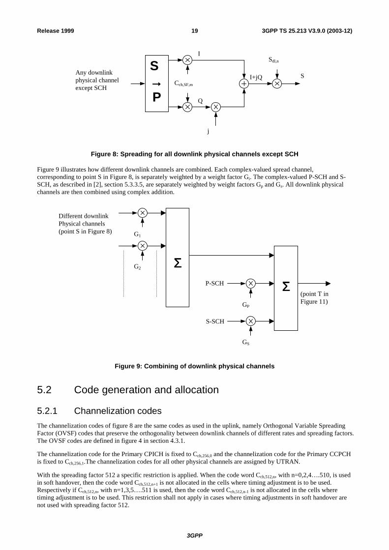
5.1 Spreading Figure 8 illustrates the spreading operation for all downlink physical channels except SCH, i.e. for P-CCPCH, S-CCPCH, CPICH, AICH, AP-AICH, CD/CA-ICH, PICH, CSICH, PDSCH, and downlink DPCH. The non-spread physical channels except SCH, AICH, AP-AICH and CD/CA-ICH consist of a sequence of 3-valued digits taking the values 0, 1, "DTX". Note that "DTX" is only applicable to those downlink physical channels that support DTX transmission. Before the spreading operation, these are mapped to real-valued symbols as follows: the binary value "0" is mapped to the real value +1, the binary value "1" is mapped to the real value –1 and "DTX" is mapped to the real value 0. For the indicator channels using signatures (AICH, AP-AICH and CD/CA-ICH), the real-valued symbols depend on the exact combination of the indicators to be transmitted, compare [2] sections 5.3.3.7, 5.3.3.8 and 5.3.3.9.
Each pair of two consecutive real-valued symbols is first serial-to-parallel converted and mapped to an I and Q branch. The mapping is such that even and odd numbered symbols are mapped to the I and Q branch respectively. For all channels except the indicator channels using signatures, symbol number zero is defined as the first symbol in each frame. For the indicator channels using signatures, symbol number zero is defined as the first symbol in each access slot. The I and Q branches are then both spread to the chip rate by the same real-valued channelization code Cch,SF,m. The channelization code sequence shall be aligned in time with the symbol boundary. The sequences of real-valued chips on the I and Q branch are then treated as a single complex-valued sequence of chips. This sequence of chips is scrambled (complex chip-wise multiplication) by a complex-valued scrambling code Sdl,n. In case of P-CCPCH, the scrambling code is applied aligned with the P-CCPCH frame boundary, i.e. the first complex chip of the spread P-CCPCH frame is multiplied with chip number zero of the scrambling code. In case of other downlink channels, the scrambling code is applied aligned with the scrambling code applied to the P-CCPCH. In this case, the scrambling code is thus not necessarily applied aligned with the frame boundary of the physical channel to be scrambled.
3GPP
3GPP TS 25.213 V3.9.0 (2003-12)19Release 1999
I
Any downlinkphysical channelexcept SCH
S→→→→P
Cch,SF,m
j
Sdl,n
Q
I+jQ S
Figure 8: Spreading for all downlink physical channels except SCH
Figure 9 illustrates how different downlink channels are combined. Each complex-valued spread channel, corresponding to point S in Figure 8, is separately weighted by a weight factor Gi. The complex-valued P-SCH and S-SCH, as described in [2], section 5.3.3.5, are separately weighted by weight factors Gp and Gs. All downlink physical channels are then combined using complex addition.
Different downlinkPhysical channels(point S in Figure 8)
ΣΣΣΣ
G1
G2
GP
GS
S-SCH
P-SCH ΣΣΣΣ(point T inFigure 11)
Figure 9: Combining of downlink physical channels
5.2 Code generation and allocation
5.2.1 Channelization codes The channelization codes of figure 8 are the same codes as used in the uplink, namely Orthogonal Variable Spreading Factor (OVSF) codes that preserve the orthogonality between downlink channels of different rates and spreading factors. The OVSF codes are defined in figure 4 in section 4.3.1.
The channelization code for the Primary CPICH is fixed to Cch,256,0 and the channelization code for the Primary CCPCH is fixed to Cch,256,1.The channelization codes for all other physical channels are assigned by UTRAN.
With the spreading factor 512 a specific restriction is applied. When the code word Cch,512,n, with n=0,2,4….510, is used in soft handover, then the code word Cch,512,n+1 is not allocated in the cells where timing adjustment is to be used. Respectively if Cch,512,n, with n=1,3,5….511 is used, then the code word Cch,512,n-1 is not allocated in the cells where timing adjustment is to be used. This restriction shall not apply in cases where timing adjustments in soft handover are not used with spreading factor 512.
3GPP
3GPP TS 25.213 V3.9.0 (2003-12)20Release 1999
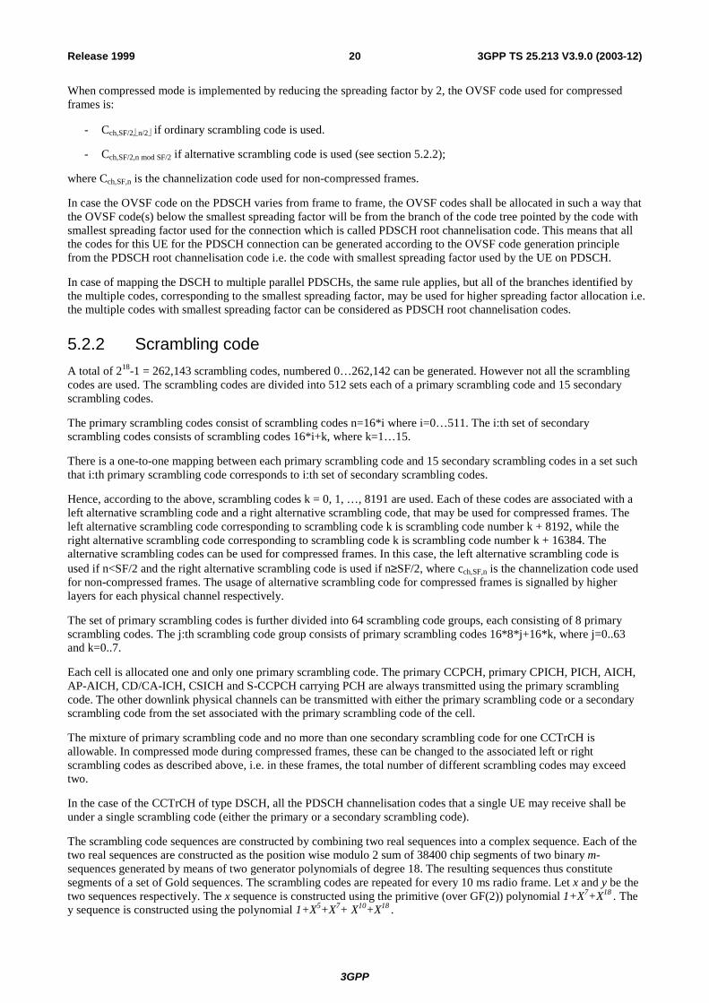
When compressed mode is implemented by reducing the spreading factor by 2, the OVSF code used for compressed frames is:
- Cch,SF/2,n/2 if ordinary scrambling code is used.
- Cch,SF/2,n mod SF/2 if alternative scrambling code is used (see section 5.2.2);
where Cch,SF,n is the channelization code used for non-compressed frames.
In case the OVSF code on the PDSCH varies from frame to frame, the OVSF codes shall be allocated in such a way that the OVSF code(s) below the smallest spreading factor will be from the branch of the code tree pointed by the code with smallest spreading factor used for the connection which is called PDSCH root channelisation code. This means that all the codes for this UE for the PDSCH connection can be generated according to the OVSF code generation principle from the PDSCH root channelisation code i.e. the code with smallest spreading factor used by the UE on PDSCH.
In case of mapping the DSCH to multiple parallel PDSCHs, the same rule applies, but all of the branches identified by the multiple codes, corresponding to the smallest spreading factor, may be used for higher spreading factor allocation i.e. the multiple codes with smallest spreading factor can be considered as PDSCH root channelisation codes.
5.2.2 Scrambling code A total of 218-1 = 262,143 scrambling codes, numbered 0…262,142 can be generated. However not all the scrambling codes are used. The scrambling codes are divided into 512 sets each of a primary scrambling code and 15 secondary scrambling codes.
The primary scrambling codes consist of scrambling codes n=16*i where i=0…511. The i:th set of secondary scrambling codes consists of scrambling codes 16*i+k, where k=1…15.
There is a one-to-one mapping between each primary scrambling code and 15 secondary scrambling codes in a set such that i:th primary scrambling code corresponds to i:th set of secondary scrambling codes.
Hence, according to the above, scrambling codes k = 0, 1, …, 8191 are used. Each of these codes are associated with a left alternative scrambling code and a right alternative scrambling code, that may be used for compressed frames. The left alternative scrambling code corresponding to scrambling code k is scrambling code number k + 8192, while the right alternative scrambling code corresponding to scrambling code k is scrambling code number k + 16384. The alternative scrambling codes can be used for compressed frames. In this case, the left alternative scrambling code is used if n<SF/2 and the right alternative scrambling code is used if n≥SF/2, where cch,SF,n is the channelization code used for non-compressed frames. The usage of alternative scrambling code for compressed frames is signalled by higher layers for each physical channel respectively.
The set of primary scrambling codes is further divided into 64 scrambling code groups, each consisting of 8 primary scrambling codes. The j:th scrambling code group consists of primary scrambling codes 16*8*j+16*k, where j=0..63 and k=0..7.
Each cell is allocated one and only one primary scrambling code. The primary CCPCH, primary CPICH, PICH, AICH, AP-AICH, CD/CA-ICH, CSICH and S-CCPCH carrying PCH are always transmitted using the primary scrambling code. The other downlink physical channels can be transmitted with either the primary scrambling code or a secondary scrambling code from the set associated with the primary scrambling code of the cell.
The mixture of primary scrambling code and no more than one secondary scrambling code for one CCTrCH is allowable. In compressed mode during compressed frames, these can be changed to the associated left or right scrambling codes as described above, i.e. in these frames, the total number of different scrambling codes may exceed two.
In the case of the CCTrCH of type DSCH, all the PDSCH channelisation codes that a single UE may receive shall be under a single scrambling code (either the primary or a secondary scrambling code).
The scrambling code sequences are constructed by combining two real sequences into a complex sequence. Each of the two real sequences are constructed as the position wise modulo 2 sum of 38400 chip segments of two binary m-sequences generated by means of two generator polynomials of degree 18. The resulting sequences thus constitute segments of a set of Gold sequences. The scrambling codes are repeated for every 10 ms radio frame. Let x and y be the two sequences respectively. The x sequence is constructed using the primitive (over GF(2)) polynomial 1+X7+X18 . The y sequence is constructed using the polynomial 1+X5+X7+ X10+X18 .

3GPP
3GPP TS 25.213 V3.9.0 (2003-12)21Release 1999
The sequence depending on the chosen scrambling code number n is denoted zn, in the sequel. Furthermore, let x(i), y(i) and zn(i) denote the i:th symbol of the sequence x, y, and zn, respectively.
The m-sequences xand y are constructed as:
Initial conditions:
- x is constructed with x (0)=1, x(1)= x(2)=...= x (16)= x (17)=0.
- y(0)=y(1)= … =y(16)= y(17)=1.
Recursive definition of subsequent symbols:
- x(i+18) =x(i+7) + x(i) modulo 2, i=0,…,218-20.
- y(i+18) = y(i+10)+y(i+7)+y(i+5)+y(i) modulo 2, i=0,…, 218-20.
The n:th Gold code sequence zn, n=0,1,2,…,218-2, is then defined as:
- zn(i) = x((i+n) modulo (218 - 1)) + y(i) modulo 2, i=0,…, 218-2.
These binary sequences are converted to real valued sequences Zn by the following transformation:
.22,,1,01)(10)(1
)( 18 −=
=−=+
= Kiforizifizif
iZn
nn
Finally, the n:th complex scrambling code sequence Sdl,n is defined as:
- Sdl,n(i) = Zn(i) + j Zn((i+131072) modulo (218-1)), i=0,1,…,38399.
Note that the pattern from phase 0 up to the phase of 38399 is repeated.
I
Q
1
1 0
02
2
3
3
4
4
5
5
6
6
7
7
8
8
9
9
17
17
16
16
15
15
14
14
13
13
12
12
11
11
10
10
Figure 10: Configuration of downlink scrambling code generator
5.2.3 Synchronisation codes
5.2.3.1 Code generation
The primary synchronisation code (PSC), Cpsc is constructed as a so-called generalised hierarchical Golay sequence. The PSC is furthermore chosen to have good aperiodic auto correlation properties.
3GPP
3GPP TS 25.213 V3.9.0 (2003-12)22Release 1999
Define:
- a = <x1, x2, x3, …, x16> = <1, 1, 1, 1, 1, 1, -1, -1, 1, -1, 1, -1, 1, -1, -1, 1>
The PSC is generated by repeating the sequence a modulated by a Golay complementary sequence, and creating a complex-valued sequence with identical real and imaginary components. The PSC Cpsc is defined as:
- Cpsc = (1 + j) × <a, a, a, -a, -a, a, -a, -a, a, a, a, -a, a, -a, a, a>;
where the leftmost chip in the sequence corresponds to the chip transmitted first in time.
The 16 secondary synchronization codes (SSCs), {Cssc,1,…,C ssc,16}, are complex-valued with identical real and imaginary components, and are constructed from position wise multiplicationof a Hadamard sequence and a sequence z, defined as:
- z = <b, b, b, -b, b, b, -b, -b, b, -b, b, -b, -b, -b, -b, -b>, where
- b = <x1, x2, x3, x4, x5, x6, x7, x8, -x9, -x10, -x11, -x12, -x13, -x14, -x15, -x16> and x1, x2 , …, x15, x16, are same as in the definition of the sequence a above.
The Hadamard sequences are obtained as the rows in a matrix H8 constructed recursively by:
1,
)1(
11
11
0
≥
−
=
=
−−
−− kHH
HHH
H
kk
kkk
The rows are numbered from the top starting with row 0 (the all ones sequence).
Denote the n:th Hadamard sequence as a row of H8 numbered from the top, n = 0, 1, 2, …, 255, in the sequel.
Furthermore, let hn(i) and z(i) denote the i:th symbol of the sequence hn and z, respectively where i = 0, 1, 2, …, 255 and i = 0 corresponds to the leftmost symbol.
The k:th SSC, Cssc,k, k = 1, 2, 3, …, 16 is then defined as:
- Cssc,k = (1 + j) × <hm(0) × z(0), hm(1) × z(1), hm(2) × z(2), …, hm(255) × z(255)>;
where m = 16×(k – 1) and the leftmost chip in the sequence corresponds to the chip transmitted first in time.
5.2.3.2 Code allocation of SSC
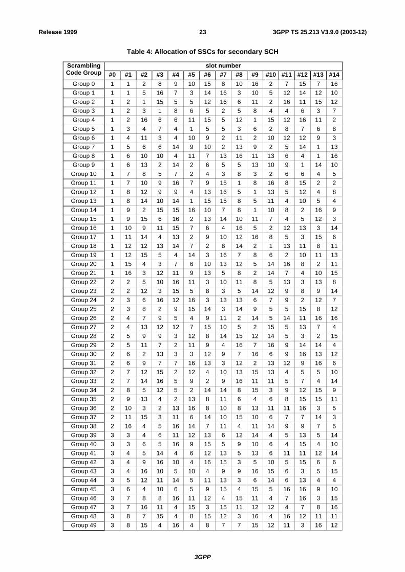
The 64 secondary SCH sequences are constructed such that their cyclic-shifts are unique, i.e., a non-zero cyclic shift less than 15 of any of the 64 sequences is not equivalent to some cyclic shift of any other of the 64 sequences. Also, a non-zero cyclic shift less than 15 of any of the sequences is not equivalent to itself with any other cyclic shift less than 15. Table 4 describes the sequences of SSCs used to encode the 64 different scrambling code groups. The entries in table 4 denote what SSC to use in the different slots for the different scrambling code groups, e.g. the entry "7" means that SSC Cssc,7 shall be used for the corresponding scrambling code group and slot.
3GPP
3GPP TS 25.213 V3.9.0 (2003-12)23Release 1999
Table 4: Allocation of SSCs for secondary SCH
slot number Scrambling Code Group #0 #1 #2 #3 #4 #5 #6 #7 #8 #9 #10 #11 #12 #13 #14
Group 0 1 1 2 8 9 10 15 8 10 16 2 7 15 7 16Group 1 1 1 5 16 7 3 14 16 3 10 5 12 14 12 10Group 2 1 2 1 15 5 5 12 16 6 11 2 16 11 15 12Group 3 1 2 3 1 8 6 5 2 5 8 4 4 6 3 7 Group 4 1 2 16 6 6 11 15 5 12 1 15 12 16 11 2 Group 5 1 3 4 7 4 1 5 5 3 6 2 8 7 6 8 Group 6 1 4 11 3 4 10 9 2 11 2 10 12 12 9 3 Group 7 1 5 6 6 14 9 10 2 13 9 2 5 14 1 13Group 8 1 6 10 10 4 11 7 13 16 11 13 6 4 1 16Group 9 1 6 13 2 14 2 6 5 5 13 10 9 1 14 10
Group 10 1 7 8 5 7 2 4 3 8 3 2 6 6 4 5 Group 11 1 7 10 9 16 7 9 15 1 8 16 8 15 2 2 Group 12 1 8 12 9 9 4 13 16 5 1 13 5 12 4 8 Group 13 1 8 14 10 14 1 15 15 8 5 11 4 10 5 4 Group 14 1 9 2 15 15 16 10 7 8 1 10 8 2 16 9 Group 15 1 9 15 6 16 2 13 14 10 11 7 4 5 12 3 Group 16 1 10 9 11 15 7 6 4 16 5 2 12 13 3 14Group 17 1 11 14 4 13 2 9 10 12 16 8 5 3 15 6 Group 18 1 12 12 13 14 7 2 8 14 2 1 13 11 8 11Group 19 1 12 15 5 4 14 3 16 7 8 6 2 10 11 13Group 20 1 15 4 3 7 6 10 13 12 5 14 16 8 2 11Group 21 1 16 3 12 11 9 13 5 8 2 14 7 4 10 15Group 22 2 2 5 10 16 11 3 10 11 8 5 13 3 13 8 Group 23 2 2 12 3 15 5 8 3 5 14 12 9 8 9 14Group 24 2 3 6 16 12 16 3 13 13 6 7 9 2 12 7 Group 25 2 3 8 2 9 15 14 3 14 9 5 5 15 8 12Group 26 2 4 7 9 5 4 9 11 2 14 5 14 11 16 16Group 27 2 4 13 12 12 7 15 10 5 2 15 5 13 7 4 Group 28 2 5 9 9 3 12 8 14 15 12 14 5 3 2 15Group 29 2 5 11 7 2 11 9 4 16 7 16 9 14 14 4 Group 30 2 6 2 13 3 3 12 9 7 16 6 9 16 13 12Group 31 2 6 9 7 7 16 13 3 12 2 13 12 9 16 6 Group 32 2 7 12 15 2 12 4 10 13 15 13 4 5 5 10Group 33 2 7 14 16 5 9 2 9 16 11 11 5 7 4 14Group 34 2 8 5 12 5 2 14 14 8 15 3 9 12 15 9 Group 35 2 9 13 4 2 13 8 11 6 4 6 8 15 15 11Group 36 2 10 3 2 13 16 8 10 8 13 11 11 16 3 5 Group 37 2 11 15 3 11 6 14 10 15 10 6 7 7 14 3 Group 38 2 16 4 5 16 14 7 11 4 11 14 9 9 7 5 Group 39 3 3 4 6 11 12 13 6 12 14 4 5 13 5 14Group 40 3 3 6 5 16 9 15 5 9 10 6 4 15 4 10Group 41 3 4 5 14 4 6 12 13 5 13 6 11 11 12 14Group 42 3 4 9 16 10 4 16 15 3 5 10 5 15 6 6 Group 43 3 4 16 10 5 10 4 9 9 16 15 6 3 5 15Group 44 3 5 12 11 14 5 11 13 3 6 14 6 13 4 4 Group 45 3 6 4 10 6 5 9 15 4 15 5 16 16 9 10Group 46 3 7 8 8 16 11 12 4 15 11 4 7 16 3 15Group 47 3 7 16 11 4 15 3 15 11 12 12 4 7 8 16Group 48 3 8 7 15 4 8 15 12 3 16 4 16 12 11 11Group 49 3 8 15 4 16 4 8 7 7 15 12 11 3 16 12

3GPP
3GPP TS 25.213 V3.9.0 (2003-12)24Release 1999
slot number Scrambling Code Group #0 #1 #2 #3 #4 #5 #6 #7 #8 #9 #10 #11 #12 #13 #14
Group 50 3 10 10 15 16 5 4 6 16 4 3 15 9 6 9 Group 51 3 13 11 5 4 12 4 11 6 6 5 3 14 13 12Group 52 3 14 7 9 14 10 13 8 7 8 10 4 4 13 9 Group 53 5 5 8 14 16 13 6 14 13 7 8 15 6 15 7 Group 54 5 6 11 7 10 8 5 8 7 12 12 10 6 9 11Group 55 5 6 13 8 13 5 7 7 6 16 14 15 8 16 15Group 56 5 7 9 10 7 11 6 12 9 12 11 8 8 6 10Group 57 5 9 6 8 10 9 8 12 5 11 10 11 12 7 7 Group 58 5 10 10 12 8 11 9 7 8 9 5 12 6 7 6 Group 59 5 10 12 6 5 12 8 9 7 6 7 8 11 11 9 Group 60 5 13 15 15 14 8 6 7 16 8 7 13 14 5 16Group 61 9 10 13 10 11 15 15 9 16 12 14 13 16 14 11Group 62 9 11 12 15 12 9 13 13 11 14 10 16 15 14 16Group 63 9 12 10 15 13 14 9 14 15 11 11 13 12 16 10
5.3 Modulation
5.3.1 Modulating chip rate The modulating chip rate is 3.84 Mcps.
5.3.2 Modulation In the downlink, the complex-valued chip sequence generated by the spreading process is QPSK modulated as shown in Figure 11 below.
T
Im{T}
Re{T}
cos(ωt)
Complex-valuedchip sequencefrom summingoperations
-sin(ωt)
Splitreal &imag.parts
Pulse-shaping
Pulse-shaping
Figure 11: Downlink modulation
The pulse-shaping characteristics are described in [4].

3GPP
3GPP TS 25.213 V3.9.0 (2003-12)25Release 1999
Annex A (informative): Generalised Hierarchical Golay Sequences
A.1 Alternative generation The generalised hierarchical Golay sequences for the PSC described in 5.2.3.1 may be also viewed as generated (in real valued representation) by the following methods:
Method 1.
The sequence y is constructed from two constituent sequences x1 and x2 of length n1 and n2 respectively using the following formula:
- y(i) = x2(i mod n2) * x1(i div n2), i = 0 ... (n1* n2) - 1.
The constituent sequences x1 and x2 are chosen to be the following length 16 (i.e. n1 = n2 =16) sequences:
- x1 is defined to be the length 16 (N(1)=4) Golay complementary sequence obtained by the delay matrix D(1) = [8, 4, 1,2] and weight matrix W(1) = [1, -1, 1,1].
- x2 is a generalised hierarchical sequence using the following formula, selecting s=2 and using the two Golay complementary sequences x3 and x4 as constituent sequences. The length of the sequence x3 and x4 is called n3 respectively n4.
- x2(i) = x4(i mod s + s*(i div sn3)) * x3((i div s) mod n3), i = 0 ... (n3* n4) - 1.
- x3 and x4 are defined to be identical and the length 4 (N(3)= N(4)=2) Golay complementary sequence obtained by the delay matrix D(3) = D(4) = [1, 2] and weight matrix W(3) = W(4) = [1, 1].
The Golay complementary sequences x1,x3 and x4 are defined using the following recursive relation:
a0(k) = δ(k) and b0(k) = δ(k);
an(k) = an-1(k) + W(j)n·bn-1(k-D(j)
n);
bn(k) = an-1(k) - W(j)n·bn-1(k-D(j)
n);
k = 0, 1, 2, …, 2**N(j) -1;
n = 1, 2, …, N(j).
The wanted Golay complementary sequence xj is defined by an assuming n=N(j). The Kronecker delta function is described by δ, k,j and n are integers.
Method 2
The sequence y can be viewed as a pruned Golay complementary sequence and generated using the following parameters which apply to the generator equations for a and b above:
(a) Let j = 0, N(0) = 8.
(b) [D10,D2
0,D30,D4
0,D50,D6
0,D70,D8
0] = [128, 64, 16, 32, 8, 1, 4, 2].
(c) [W10,W2
0,W30,W4
0,W50,W6
0,W70,W8
0] = [1, -1, 1, 1, 1, 1, 1, 1].
(d) For n = 4, 6, set b4(k) = a4(k), b6(k) = a6(k).

3GPP
3GPP TS 25.213 V3.9.0 (2003-12)26Release 1999
Annex B (informative): Change history
Change history Date TSG # TSG Doc. CR Rev Subject/Comment Old New
14/01/00 RAN_05 RP-99589 - Approved at TSG RAN #5 and placed under Change Control
- 3.0.0
14/01/00 RAN_06 RP-99682 005 1 Harmonization of notations for downlink scrambling codes 3.0.0 3.1.014/01/00 RAN_06 RP-99683 006 - Update of downlink spreading description 3.0.0 3.1.014/01/00 RAN_06 RP-99682 007 1 Update of TS 25.213 uplink parts 3.0.0 3.1.014/01/00 RAN_06 RP-99683 008 - Updated modulation description 3.0.0 3.1.014/01/00 RAN_06 RP-99683 009 - Restriction for spreading factor 512 allocation in the UTRA
FDD Downlink 3.0.0 3.1.0
14/01/00 RAN_06 RP-99683 011 1 CPCH codes in power control preamble 3.0.0 3.1.014/01/00 RAN_06 RP-99683 012 2 Support of short codes for CPCH 3.0.0 3.1.014/01/00 RAN_06 RP-99682 014 1 Editorial Change 3.0.0 3.1.014/01/00 RAN_06 RP-99683 016 - Channelization Code Allocation for USTS 3.0.0 3.1.014/01/00 RAN_06 RP-99683 017 1 Correction (Editorial Change) 3.0.0 3.1.014/01/00 RAN_06 RP-99683 019 - Correction to code allocation for compressed mode 3.0.0 3.1.014/01/00 - - - Change history was added by the editor 3.1.0 3.1.131/03/00 RAN_07 RP-000063 020 1 Consistent numbering of scrambling code groups 3.1.1 3.2.031/03/00 RAN_07 RP-000063 021 - Downlink signal flow corrections 3.1.1 3.2.031/03/00 RAN_07 RP-000063 022 - Uplink signal flow corrections 3.1.1 3.2.031/03/00 RAN_07 RP-000063 023 1 Number of RACH scrambling codes 3.1.1 3.2.031/03/00 RAN_07 RP-000063 024 1 Editorial changes to 25.213 3.1.1 3.2.031/03/00 RAN_07 RP-000063 025 3 Number of PCPCH scrambling codes per cell 3.1.1 3.2.031/03/00 RAN_07 RP-000063 027 - A typo correction for 5.2.2 and clarification for 5.2.3.1 of TS
25.213V3.1.1 3.1.1 3.2.0
31/03/00 RAN_07 RP-000063 028 2 Channelization code allocation method for PCPCH message part
3.1.1 3.2.0
31/03/00 RAN_07 RP-000063 029 - Clarifications to DSCH scrambling and modulation in 25.213 3.1.1 3.2.031/03/00 RAN_07 RP-000063 032 - Clean up of USTS related specifications 3.1.1 3.2.026/06/00 RAN_08 RP-000267 033 - Clarifications to power control preamble sections 3.2.0 3.3.026/06/00 RAN_08 RP-000267 034 2 Numbering of the PCPCH access preamble and collision detection
preamble scrambling codes 3.2.0 3.3.0
26/06/00 RAN_08 RP-000267 035 - DPDCH/DPCCH gain factors 3.2.0 3.3.016/12/00 RAN_10 RP-000539 037 1 Proposed removal of the option of secondary scrambling code for
some downlink common channels 3.3.0 3.4.0
16/03/01 RAN_11 RP-010059 038 - Clarification of channelization codes when SF=512 3.4.0 3.5.016/03/01 RAN_11 RP-010059 039 1 Clarification of the scrambling code of a power control preamble 3.4.0 3.5.015/06/01 RAN_12 RP-010333 040 1 Clarification of DL channelization code alignment 3.5.0 3.6.015/06/01 RAN_12 RP-010333 042 1 Clarification of PDSCH root channelisation code definition 3.5.0 3.6.014/12/01 RAN_14 RP-010738 046 - Correction of section number reference 3.6.0 3.7.007/06/02 RAN_16 RP-020309 051 1 Downlink bit mapping 3.7.0 3.8.006/01/04 RAN_22 RP-030727 068 1 Restriction of DL secondary scrambling codes per CCTrCH 3.8.0 3.9.0
Related Documents