3GPP TS 24.007 V8.2.0 (2009-06) Technical Specification 3rd Generation Partnership Project; Technical Specification Group Core Network and Terminals; Mobile radio interface signalling layer 3; General aspects (Release 8) The present document has been developed within the 3 rd Generation Partnership Project (3GPP TM ) and may be further elaborated for the purposes of 3GPP. The present document has not been subject to any approval process by the 3GPP Organisational Partners and shall not be implemented. This Specification is provided for future development work within 3GPP only. The Organisational Partners accept no liability for any use of this Specification. Specifications and reports for implementation of the 3GPP TM system should be obtained via the 3GPP Organisational Partners' Publications Offices.

Welcome message from author
This document is posted to help you gain knowledge. Please leave a comment to let me know what you think about it! Share it to your friends and learn new things together.
Transcript
8/3/2019 3GPP TS 24007-V8.2.0
http://slidepdf.com/reader/full/3gpp-ts-24007-v820 1/149

8/3/2019 3GPP TS 24007-V8.2.0
http://slidepdf.com/reader/full/3gpp-ts-24007-v820 2/149
3GPP
3GPP TS 24.007 V8.2.0 (2009-06)2Release 8
Keywords
GSM, UMTS, layer 3, network, LTE
3GPP
Postal address
3GPP support office address
650 Route des Lucioles - Sophia Antipolis
Valbonne - FRANCETel.: +33 4 92 94 42 00 Fax: +33 4 93 65 47 16
Internet
http://www.3gpp.org
Copyright Notification
No part may be reproduced except as authorized by written permission.
The copyright and the foregoing restriction extend to reproduction in all media.
© 2009, 3GPP Organizational Partners (ARIB, ATIS, CCSA, ETSI, TTA, TTC).
All rights reserved.
UMTS™ is a Trade Mark of ETSI registered for the benefit of its members
3GPP™ is a Trade Mark of ETSI registered for the benefit of its Members and of the 3GPP Organizational Partners
LTE™ is a Trade Mark of ETSI currently being registered for the benefit of i ts Members and of the 3GPP Organizational Partners
GSM® and the GSM logo are registered and owned by the GSM Association
8/3/2019 3GPP TS 24007-V8.2.0
http://slidepdf.com/reader/full/3gpp-ts-24007-v820 3/149
3GPP
3GPP TS 24.007 V8.2.0 (2009-06)3Release 8
Contents
Foreword........................................................................................................................................................... 12
1 Scope ...................................................................................................................................................... 13 2 References .............................................................................................................................................. 13
3 Definitions and abbreviations ................................................................................................................. 15 3.1 Definitions ....................................................................................................................................................... 15 3.2 Abbreviations ....................................................... .............................................................. .............................. 15
4 Introduction ............................................................................................................................................ 15 4.1 General ...................................................... ................................................................. ...................................... 15 4.2 Applicability of functional blocks ................................................................................................................... 17 4.3 Technique of description ................................................................................................................................. 17 4.3.1 Service description ..................................................................................................................................... 17 4.3.2 Abstract service primitives ............................................................. ............................................................ 17
4.3.3 Protocols and peer-to-peer communication .......................................................... ...................................... 18 4.3.4 Contents of layer 3 related Technical Specifications ................................................................................. 19
5 Structure of layer 3 functions ................................................................................................................. 20 5.1 Basic groups of functions ................................................................................................................................ 20 5.2 Protocol architecture ................................................................. ............................................................... ........ 21
6 Services provided by signalling layer 3 at the MS side.......................................................................... 31 6.1 Registration services ................................................................. ............................................................... ........ 31 6.1.1 Service state diagram for MS not supporting GPRS service .............................................................. ........ 32 6.1.2 Service primitives ................................................................ ............................................................... ........ 32 6.1.2.1 MMR_REG_REQ ................................................................................................................................ 32 6.1.2.2 MMR_REG_CNF .......................................................... ............................................................... ........ 32 6.1.2.3 Void ...................................................................................................................................................... 32 6.1.2.4 MMR_NREG_REQ ............................................................................................................................. 32 6.1.2.5 MMR_NREG_IND .............................................................................................................................. 33 6.1.3 Registration Services for CTS-Services ..................................................................................................... 33 6.1.3.1 MMR_CTS _ATTACH_REQ ............................................................. ................................................. 33 6.1.3.2 MMR_CTS _ATTACH_CNF ............................................................. ................................................. 33 6.1.3.3 MMR_CTS _ATTACH_REJ ............................................................................................................... 33 6.1.3.4 MMR_CTS _DETACH_IND .............................................................. ................................................. 33 6.1.3.5 MMR_CTS _ENROLL_REQ .............................................................................................................. 33 6.1.3.6 MMR_CTS _ENROLL_CNF .............................................................. ................................................. 33 6.1.3.7 MMR_CTS _ENROLL_REJ ............................................................... ................................................. 33 6.1.3.8 MMR_CTS _DE_ENROLL_IND ....................................................... ................................................. 34 6.2 Call Control services ................................................................. ............................................................... ........ 34 6.2.1 Service state diagram ................................................................................................................................. 34 6.2.2 Service primitives ................................................................ ............................................................... ........ 37 6.2.2.1 MNCC_SETUP_REQ .......................................................................................................................... 37 6.2.2.2 MNCC_SETUP_IND ............................................................... ............................................................ 37 6.2.2.3 MNCC_SETUP_RES ............................................................... ............................................................ 37 6.2.2.4 MNCC_SETUP_CNF .......................................................................................................................... 37 6.2.2.5 MNCC_SETUP_COMPL_REQ........................................................................................................... 37 6.2.2.6 MNCC_SETUP_COMPL_IND ........................................................................................................... 38 6.2.2.7 MNCC_REJ_REQ ......................................................... ............................................................... ........ 38 6.2.2.8 MNCC_REJ_IND .......................................................... ............................................................... ........ 38 6.2.2.9 MNCC_CALL_CONF_REQ ............................................................................................................... 38 6.2.2.10 MNCC_CALL_PROC_IND ................................................................................................................ 38 6.2.2.11 MNCC_PROGRESS_IND ....................................................... ............................................................ 38 6.2.2.12 MNCC_ALERT_REQ.......................................................................................................................... 38 6.2.2.13 MNCC_ALERT_IND .......................................................................................................................... 38 6.2.2.14 MNCC_NOTIFY_REQ ............................................................ ............................................................ 38 6.2.2.15 MNCC_NOTIFY_IND ............................................................. ............................................................ 38
8/3/2019 3GPP TS 24007-V8.2.0
http://slidepdf.com/reader/full/3gpp-ts-24007-v820 4/149
3GPP
3GPP TS 24.007 V8.2.0 (2009-06)4Release 8
6.2.2.16 MNCC_DISC_REQ ............................................................................................................................. 38 6.2.2.17 MNCC_DISC_IND .............................................................................................................................. 38 6.2.2.18 MNCC_REL_REQ ........................................................ ............................................................... ........ 39 6.2.2.19 MNCC_REL_IND ......................................................... ............................................................... ........ 39 6.2.2.20 MNCC_REL_CNF ........................................................ ............................................................... ........ 39 6.2.2.21 MNCC_FACILITY_REQ .................................................................................................................... 39
6.2.2.22 MNCC_FACILITY_IND ......................................................... ............................................................ 39 6.2.2.23 MNCC_START_DTMF_REQ ............................................................ ................................................. 39 6.2.2.24 MNCC_START_DTMF_CNF ............................................................ ................................................. 39 6.2.2.25 MNCC_STOP_DTMF_REQ ............................................................... ................................................. 39 6.2.2.26 MNCC_STOP_DTMF_CNF ............................................................... ................................................. 39 6.2.2.27 MNCC_MODIFY_REQ ........................................................... ............................................................ 39 6.2.2.28 MNCC_MODIFY_IND........................................................................................................................ 39 6.2.2.29 MNCC_MODIFY_RES ....................................................................................................................... 39 6.2.2.30 MNCC_MODIFY_CNF ........................................................... ............................................................ 40 6.2.2.31 MNCC_SYNC_IND ................................................................. ............................................................ 40 6.3 Call independent Supplementary Services Support ......................................................................................... 40 6.3.1 Service state diagram ................................................................................................................................. 40 6.3.2 Service primitives ................................................................ ............................................................... ........ 40
6.3.2.1 MNSS_BEGIN_REQ ............................................................... ............................................................ 41 6.3.2.2 MNSS_BEGIN_IND ................................................................ ............................................................ 41 6.3.2.3 MNSS_FACILITY_REQ ..................................................................................................................... 41 6.3.2.4 MNSS_FACILITY_IND .......................................................... ............................................................ 41 6.3.2.5 MNSS_END_REQ ........................................................ ............................................................... ........ 41 6.3.2.6 MNSS_END_IND ......................................................... ............................................................... ........ 41 6.4 Short Message Services Support .......................................................... ............................................................ 41 6.5 Session Management Services for GPRS-Services ............................................................ .............................. 41 6.5.1 Session Management Services for SMREG-SAP ...................................................................................... 42 6.5.1.1 SMREG-PDP-ACTIVATE-REQ ......................................................................................................... 42 6.5.1.2 SMREG-PDP-ACTIVATE-CNF ......................................................................................................... 42 6.5.1.3 SMREG-PDP-ACTIVATE-REJ .......................................................... ................................................. 42 6.5.1.4 SMREG-PDP-ACTIVATE-IND ......................................................... ................................................. 43
6.5.1.5 SMREG-PDP-DEACTIVATE-REQ .............................................................. ...................................... 43 6.5.1.6 SMREG-PDP-DEACTIVATE-CNF .............................................................. ...................................... 43 6.5.1.7 SMREG-PDP-DEACTIVATE-IND ............................................................... ...................................... 43 6.5.1.8 SMREG-PDP-MODIFY-IND .............................................................................................................. 43 6.5.1.9 Void ...................................................................................................................................................... 43 6.5.1.10 Void ...................................................................................................................................................... 43 6.5.1.11 Void ...................................................................................................................................................... 43 6.5.1.12 Void ...................................................................................................................................................... 43 6.5.1.13 Void ...................................................................................................................................................... 43 6.5.1.14 SMREG-PDP-ACTIVATE-REJ-RSP ............................................................ ...................................... 43 6.5.1.15 SMREG-PDP-ACTIVATE-SEC-REQ ........................................................... ...................................... 43 6.5.1.16 SMREG-PDP-ACTIVATE-SEC-CNF ........................................................... ...................................... 44 6.5.1.17 SMREG-PDP-ACTIVATE-SEC-REJ ............................................................ ...................................... 44
6.5.1.18 SMREG-PDP-MODIFY-REQ ............................................................................................................. 44 6.5.1.19 SMREG-PDP-MODIFY-CNF ............................................................. ................................................. 44 6.5.1.20 SMREG-PDP-MODIFY-REJ .............................................................. ................................................. 44 6.5.1.21 SMREG-MBMS-ACTIVATE-REQ ............................................................... ...................................... 44 6.5.1.22 SMREG-MBMS-ACTIVATE-CNF ............................................................... ...................................... 44 6.5.1.23 SMREG-MBMS-ACTIVATE-REJ ................................................................ ...................................... 44 6.5.1.24 SMREG-MBMS-ACTIVATE-REJ-RSP.............................................................................................. 44 6.5.1.25 SMREG-MBMS-ACTIVATE-IND ..................................................................................................... 44 6.5.2 Session Management Services for SNSM-SAP (GSM only) ..................................................................... 46 6.5.3 Session Management Services for RABMSM-SAP (UMTS only) ............................................................ 46 6.5.3.1 RABMSM-ACTIVATE-IND .............................................................. ................................................. 47 6.5.3.2 RABMSM-ACTIVATE-RSP .............................................................. ................................................. 47 6.5.3.3 RABMSM-DEACTIVATE-IND ......................................................... ................................................. 47
6.5.3.4 RABMSM-DEACTIVATE-RSP ......................................................... ................................................. 47 6.5.3.5 RABMSM-DEACTIVATE-REQ ........................................................ ................................................. 47 6.5.3.6 RABMSM-MODIFY-IND ....................................................... ............................................................ 47 6.5.3.7 RABMSM-MODIFY-RSP ....................................................... ............................................................ 47

8/3/2019 3GPP TS 24007-V8.2.0
http://slidepdf.com/reader/full/3gpp-ts-24007-v820 5/149
3GPP
3GPP TS 24.007 V8.2.0 (2009-06)5Release 8
6.5.3.8 RABMSM-STATUS-REQ ....................................................... ............................................................ 47 6.6 Registration Services for GPRS-Services ....................................................... ................................................. 47 6.6.1 Registration Services for GMMREG-SAP ........................................................... ...................................... 48 6.6.1.1 GMMREG-ATTACH-REQ ................................................................................................................. 48 6.6.1.2 GMMREG-ATTACH-CNF ................................................................ .................................................. 48 6.6.1.3 GMMREG-ATTACH-REJ ....................................................... ............................................................ 48
6.6.1.4 GMMREG-DETACH-REQ ................................................................................................................. 48 6.6.1.5 GMMREG-DETACH-CNF ................................................................ .................................................. 48 6.6.1.6 GMMREG-DETACH-IND .................................................................................................................. 48 6.7 Services provided to SNDCP entities by GPRS Logical Link Control services .............................................. 49 6.7.1 Service state diagram for QoS1-SAP, QoS2-SAP, QoS3-SAP and QoS4-SAP ......................................... 50 6.7.2 Service primitives for QoS1-SAP, QoS2-SAP, QoS3-SAP and QoS4-SAP .............................................. 50 6.7.2.1 LL-ESTABLISH-REQ ......................................................................................................................... 50 6.7.2.2 LL-ESTABLISH-CNF ......................................................................................................................... 51 6.7.2.3 LL-ESTABLISH-IND .......................................................................................................................... 51 6.7.2.4 LL-ESTABLISH-RSP .......................................................................................................................... 51 6.7.2.5 LL-RELEASE-REQ ............................................................................................................................. 51 6.7.2.6 LL-RELEASE-CNF ............................................................................................................................. 51 6.7.2.7 LL-RELEASE-IND .............................................................................................................................. 51
6.7.2.8 LL-XID-REQ ....................................................................................................................................... 51 6.7.2.9 LL-XID-IND ........................................................................................................................................ 51 6.7.2.10 LL-XID-RSP ........................................................................................................................................ 51 6.7.2.11 LL-XID-CNF ................................................................. ............................................................... ........ 51 6.7.2.12 LL-DATA-REQ ................................................................................................................................... 51 6.7.2.13 LL-DATA-CNF ............................................................. ............................................................... ........ 51 6.7.2.14 LL-DATA-IND .................................................................................................................................... 51 6.7.2.15 LL-UNITDATA-REQ .............................................................. ............................................................ 51 6.7.2.16 LL-UNITDATA-IND ............................................................... ............................................................ 52 6.7.2.17 LL-STATUS-IND ................................................................................................................................ 52 6.8 Location services at the type A LMU side ................................................................ ....................................... 52 6.8.1 Service state diagram ................................................................................................................................. 52 6.8.2 Service primitives ................................................................ ............................................................... ........ 53
6.8.2.1 MNLCS_BEGIN_REQ ........................................................................................................................ 53 6.8.2.2 MNLCS_BEGIN_IND ............................................................. ............................................................ 53 6.8.2.3 MNLCS_FACILITY_REQ .................................................................................................................. 53 6.8.2.4 MNLCS_FACILITY_IND ................................................................................................................... 53 6.8.2.5 MNLCS_END_REQ ............................................................................................................................ 53 6.8.2.6 MNLCS_END_IND ................................................................. ............................................................ 53
7 Services provided by signalling layer 3 on the Network side ................................................................ 53 7.1 Call control services......................................................................................................................................... 53 7.1.1 Service state diagram ................................................................................................................................. 54 7.1.2 Service primitives ................................................................ ............................................................... ........ 57 7.1.2.1 MNCC_SETUP_REQ .......................................................................................................................... 57 7.1.2.2 MNCC_SETUP_IND ............................................................... ............................................................ 57
7.1.2.3 MNCC_SETUP_RSP ............................................................... ............................................................ 57 7.1.2.4 MNCC_SETUP_CNF .......................................................................................................................... 57 7.1.2.5 MNCC_SETUP_COMPL_REQ........................................................................................................... 57 7.1.2.6 MNCC_SETUP_COMPL_IND ........................................................................................................... 58 7.1.2.7 MNCC_REJ_REQ ......................................................... ............................................................... ........ 58 7.1.2.8 MNCC_REJ_IND .......................................................... ............................................................... ........ 58 7.1.2.9 MNCC_CALL_CONF_IND ................................................................................................................ 58 7.1.2.10 MNCC_CALL_PROC_REQ ............................................................... ................................................. 58 7.1.2.11 MNCC_PROGRESS_REQ .................................................................................................................. 58 7.1.2.12 MNCC_ALERT_REQ.......................................................................................................................... 58 7.1.2.13 MNCC_ALERT_IND .......................................................................................................................... 58 7.1.2.14 MNCC_NOTIFY_REQ ............................................................ ............................................................ 58 7.1.2.15 MNCC_NOTIFY_IND ............................................................. ............................................................ 58
7.1.2.16 MNCC_DISC_REQ ............................................................................................................................. 58 7.1.2.17 MNCC_DISC_IND .............................................................................................................................. 58 7.1.2.18 MNCC_REL_REQ ........................................................ ............................................................... ........ 59 7.1.2.19 MNCC_REL_IND ......................................................... ............................................................... ........ 59
8/3/2019 3GPP TS 24007-V8.2.0
http://slidepdf.com/reader/full/3gpp-ts-24007-v820 6/149
3GPP
3GPP TS 24.007 V8.2.0 (2009-06)6Release 8
7.1.2.20 MNCC_REL_CNF ........................................................ ............................................................... ........ 59 7.1.2.21 MNCC_FACILITY_REQ .................................................................................................................... 59 7.1.2.22 MNCC_FACILITY_IND ......................................................... ............................................................ 59 7.1.2.23 MNCC_START_DTMF_IND ............................................................. ................................................. 59 7.1.2.24 MNCC_START_DTMF_RSP ............................................................. ................................................. 59 7.1.2.25 MNCC_STOP_DTMF_IND ................................................................................................................ 59
7.1.2.26 MNCC_STOP_DTMF_RSP ................................................................................................................ 59 7.1.2.27 MNCC_MODIFY_REQ ........................................................... ............................................................ 59 7.1.2.28 MNCC_MODIFY_IND........................................................................................................................ 59 7.1.2.29 MNCC_MODIFY_RES ....................................................................................................................... 59 7.1.2.30 MNCC_MODIFY_CNF ........................................................... ............................................................ 59 7.2 Call independent Supplementary Services Support ......................................................................................... 60 7.2.1 Service state diagram ................................................................................................................................. 60 7.2.2 Service primitives ................................................................ ............................................................... ........ 60 7.2.2.1 MNSS_BEGIN_REQ ............................................................... ............................................................ 60 7.2.2.2 MNSS_BEGIN_IND ................................................................ ............................................................ 61 7.2.2.3 MNSS_FACILITY_REQ ..................................................................................................................... 61 7.2.2.4 MNSS_FACILITY_IND .......................................................... ............................................................ 61 7.2.2.5 MNSS_END_REQ ........................................................ ............................................................... ........ 61
7.2.2.6 MNSS_END_IND ......................................................... ............................................................... ........ 61 7.3 Short Message Services Support .......................................................... ............................................................ 61 7.4 Services provided to SNDCP and SMS entities by GPRS Logical Link Control services .............................. 61 7.4.1 Service state diagram for QoS1-SAP, QoS2-SAP, QoS3-SAP and QoS4-SAP ......................................... 61 7.4.2 Service primitives for QoS1-SAP, QoS2-SAP, QoS3-SAP and QoS4-SAP .............................................. 62 7.4.2.1 LL-ESTABLISH-REQ ......................................................................................................................... 62 7.4.2.2 LL-ESTABLISH-CNF ......................................................................................................................... 62 7.4.2.3 LL-ESTABLISH-IND .......................................................................................................................... 62 7.4.2.4 LL-ESTABLISH-RSP .......................................................................................................................... 62 7.4.2.5 LL-RELEASE-REQ ............................................................................................................................. 62 7.4.2.6 LL-RELEASE-CNF ............................................................................................................................. 62 7.4.2.7 LL-RELEASE-IND .............................................................................................................................. 62 7.4.2.8 LL-XID-REQ ....................................................................................................................................... 62
7.4.2.9 LL-XID-IND ........................................................................................................................................ 63 7.4.2.10 LL-XID-RSP ........................................................................................................................................ 63 7.4.2.11 LL-XID-CNF ................................................................. ............................................................... ........ 63 7.4.2.12 LL-DATA-REQ ................................................................................................................................... 63 7.4.2.13 LL-DATASENT-IND .......................................................................................................................... 63 7.4.2.14 LL-DATA-CNF ............................................................. ............................................................... ........ 63 7.4.2.15 LL-DATA-IND .................................................................................................................................... 63 7.4.2.16 LL-UNITDATA-REQ .............................................................. ............................................................ 63 7.4.2.17 LL-UNITDATA-IND ............................................................... ............................................................ 63 7.4.2.18 LL-STATUS-IND ................................................................................................................................ 63 7.5 Session Management Services for GPRS and MBMS ....................................................... .............................. 63 7.5.1 Session Management Services for SMREG-SAP ...................................................................................... 64 7.5.1.1 SMREG-PDP-ACTIVATE-REQ ......................................................................................................... 64
7.5.1.2 SMREG-PDP-ACTIVATE-REJ .......................................................... ................................................. 64 7.5.1.3 SMREG-PDP-DEACTIVATE-REQ .............................................................. ...................................... 64 7.5.1.4 SMREG-PDP-DEACTIVATE-CNF .............................................................. ...................................... 64 7.5.1.5 SMREG-PDP-MODIFY-REQ ............................................................................................................. 64 7.5.1.6 SMREG-PDP-MODIFY-CNF ............................................................. ................................................. 64 7.5.1.7 SMREG-PDP-MODIFY-REJ .............................................................. ................................................. 65 7.5.1.8 SMREG-MBMS-ACTIVATE-REQ ............................................................... ...................................... 65 7.5.1.9 SMREG-MBMS-ACTIVATE-REJ ................................................................ ...................................... 65 7.5.2 Session Management Services for SNSM-SAP ......................................................................................... 65 7.6 Location services at the Network side ............................................................................................................. 65 7.6.1 Service state diagram ................................................................................................................................. 65 7.6.2 Service primitives ................................................................ ............................................................... ........ 66 7.6.2.1 MNLCS_BEGIN_REQ ........................................................................................................................ 66
7.6.2.2 MNLCS_BEGIN_IND ............................................................. ............................................................ 67 7.6.2.3 MNLCS_FACILITY_REQ .................................................................................................................. 67 7.6.2.4 MNLCS_FACILITY_IND ................................................................................................................... 67 7.6.2.5 MNLCS_END_REQ ............................................................................................................................ 67
8/3/2019 3GPP TS 24007-V8.2.0
http://slidepdf.com/reader/full/3gpp-ts-24007-v820 7/149
3GPP
3GPP TS 24.007 V8.2.0 (2009-06)7Release 8
7.6.2.6 MNLCS_END_IND ................................................................. ............................................................ 67
8 Services assumed from signalling layers 1 and 2 ................................................................................... 67 8.1 Priority ............................................................................................................................................................. 67 8.2 Unacknowledged information transfer ............................................................ ................................................. 67 8.3 Acknowledged information transfer ................................................................................................................ 67 8.4 Random access ................................................................ .............................................................. ................... 68 8.5 Channel management and measurements ........................................................................................................ 68
9 Interlayer service interfaces on the MS side .......................................................................................... 68 9.1 Services provided by the Radio Resource Management entity ..................................................... ................... 68 9.1.1 Service state diagram ................................................................................................................................. 69 9.1.2 Service primitives ................................................................ ............................................................... ........ 70 9.1.2.1 RR_EST_REQ ............................................................... ............................................................... ........ 70 9.1.2.2 RR_EST_IND....................................................................................................................................... 70 9.1.2.3 RR_EST_CNF ............................................................... ............................................................... ........ 70 9.1.2.4 RR_REL_IND ...................................................................................................................................... 70 9.1.2.5 RR_SYNC_IND ............................................................ ............................................................... ........ 71 9.1.2.5a Void ...................................................................................................................................................... 71 9.1.2.5b Void ...................................................................................................................................................... 71
9.1.2.6 RR_DATA_REQ ........................................................... ............................................................... ........ 71 9.1.2.7 RR_DATA_IND ............................................................ ............................................................... ........ 71 9.1.2.7a Void ...................................................................................................................................................... 71 9.1.2.8 RR_UNIT_DATA_IND ........................................................... ............................................................ 71 9.1.2.9 RR_ABORT_REQ ............................................................................................................................... 71 9.1.2.10 RR_ABORT_IND ................................................................................................................................ 71 9.1.3 Services provided by the Radio Resource Management entity for CTS ........... ......................................... 72 9.1.3.1 CTS_RR_ALIVE_CHECK_IND ........................................................ ................................................. 72 9.2 Services provided by the Mobility Management entity ..................................................... .............................. 72 9.2.1 Service state diagram ................................................................................................................................. 73 9.2.2 Service primitives ................................................................ ............................................................... ........ 74 9.2.2.1 MMXX_EST_REQ .............................................................................................................................. 74 9.2.2.2 MMXX_EST_IND ........................................................ ............................................................... ........ 74 9.2.2.3 MMXX_EST_CNF .............................................................................................................................. 74 9.2.2.4 MMXX_REL_REQ ....................................................... ............................................................... ........ 74 9.2.2.5 MMXX_REL_IND ........................................................ ............................................................... ........ 74 9.2.2.6 MMXX_DATA_REQ .......................................................................................................................... 74 9.2.2.7 MMXX_DATA_IND ............................................................... ............................................................ 75 9.2.2.8 MMXX_UNIT_DATA_REQ .............................................................. ................................................. 75 9.2.2.9 MMXX_UNIT_DATA_IND ............................................................... ................................................. 75 9.2.2.10 MMCC_SYNC_IND ................................................................ ............................................................ 75 9.2.2.11 MMXX_REEST_REQ ............................................................. ............................................................ 75 9.2.2.12 MMXX_REEST_CNF ......................................................................................................................... 75 9.2.2.13 MMXX_ERR_IND .............................................................................................................................. 75 9.2.2.14 MMXX_PROMPT_IND ...................................................................................................................... 75 9.2.2.15 MMXX_PROMPT_REJ ........................................................... ............................................................ 75 9.3 Services provided by radio resource management entity for GPRS services .................................................. 76 9.3.1 Service primitives for GRR-SAP (GSM only) ............................................................. .............................. 76 9.3.2 Service primitives for GMMRR-SAP (GSM only) ...................................................... .............................. 76 9.3.2.1 GMMRR-ASSIGN-REQ .......................................................... ............................................................ 76 9.3.2.2 GMMRR-PAGE-IND ............................................................... ............................................................ 76 9.3.3 Service primitives for RABMAS-SAP (UMTS only) ............................................................. ................... 76 9.3.3.1 RABMAS-RAB-ESTABLISH-IND ............................................................... ...................................... 76 9.3.3.2 RABMAS-RAB-ESTABLISH-RES .................................................................................................... 76 9.3.3.3 RABMAS-RAB-ESTABLISH-REJ ............................................................... ...................................... 77 9.3.3.4 RABMAS-RAB-RELEASE-IND ........................................................ ................................................. 77 9.3.3.5 RABMAS-RAB-RELEASE-RES ........................................................................................................ 77 9.3.3.6 RABMAS-STATUS-IND .................................................................................................................... 77 9.3.4 Service primitives for GMMAS-SAP (UMTS only) ............................................................... ................... 77 9.3.4.1 GMMAS-SECURITY-IND ................................................................ .................................................. 77 9.3.4.2 GMMAS-SECURITY-RES ................................................................ .................................................. 77 9.3.4.3 GMMAS-ESTABLISH-REQ .............................................................. ................................................. 77
8/3/2019 3GPP TS 24007-V8.2.0
http://slidepdf.com/reader/full/3gpp-ts-24007-v820 8/149
3GPP
3GPP TS 24.007 V8.2.0 (2009-06)8Release 8
9.3.4.4 GMMAS-ESTABLISH-CNF ............................................................................................................... 77 9.3.4.5 GMMAS-ESTABLISH-REJ ................................................................................................................ 78 9.3.4.6 GMMAS- RELEASE-REQ ................................................................ .................................................. 78 9.3.4.7 GMMAS- RELEASE-IND ....................................................... ............................................................ 78 9.3.4.8 GMMAS- DATA-REQ ........................................................................................................................ 78 9.3.4.9 GMMAS- DATA-IND ......................................................................................................................... 78
9.3.4.10 GMMAS-PAGE-IND ............................................................... ............................................................ 78 9.3.4.11 GMMAS-STATUS-IND ...................................................................................................................... 78 9.4 Services provided by the LLC entity for GPRS services (GSM only) ..................................................... ........ 78 9.4.1 Service primitives for LLGMM-SAP ........................................................ ................................................. 78 9.4.1.1 LLGMM-ASSIGN-REQ ...................................................................................................................... 78 9.4.1.2 LLGMM-TRIGGER-REQ ................................................................................................................... 78 9.4.1.3 Void ...................................................................................................................................................... 79 9.4.1.4 LLGMM-SUSPEND-REQ ....................................................... ............................................................ 79 9.4.1.5 Void ...................................................................................................................................................... 79 9.4.1.6 Void ...................................................................................................................................................... 79 9.4.1.7 LLGMM-WINDOW-CNF ................................................................................................................... 79 9.4.1.8 LL-UNITDATA-REQ .............................................................. ............................................................ 79 9.4.1.9 LL-UNITDATA-IND ............................................................... ............................................................ 79
9.4.1.10 LLGMM-STATUS-IND ...................................................................................................................... 79 9.4.2 Service primitives for LLSMS-SAP .......................................................... ................................................. 79 9.4.2.1 LL-UNITDATA-REQ .............................................................. ............................................................ 79 9.4.2.2 LL-UNITDATA-IND ............................................................... ............................................................ 79 9.5 Services provided by the GMM for GPRS services ........................................................... .............................. 79 9.5.1 Service primitives for GMMSM-SAP ....................................................... ................................................. 79 9.5.1.1 GMMSM-ESTABLISH-REQ .............................................................................................................. 80 9.5.1.2 GMMSM-ESTABLISH-CNF .............................................................................................................. 80 9.5.1.3 GMMSM-ESTABLISH-REJ ............................................................... ................................................. 80 9.5.1.4 GMMSM-RELEASE-IND ................................................................................................................... 80 9.5.1.5 GMMSM-UNITDATA-REQ .............................................................. ................................................. 80 9.5.1.6 GMMSM-UNITDATA-IND ............................................................... ................................................. 80 9.5.2 Void ..................................................... .............................................................. ......................................... 80
9.5.3 Service primitives for GMMSMS-SAP...................................................................................................... 80 9.5.3.1 GMMSMS-REG-STATE-REQ ........................................................... ................................................. 81 9.5.3.2 GMMSM- REG-STATE -RSP ............................................................ ................................................. 81 9.5.4 Service primitives for PMMSMS-SAP ...................................................................................................... 81 9.5.4.1 PMMSMS_EST _REQ ............................................................. ............................................................ 81 9.5.4.2 PMMSMS_EST _CNF ............................................................. ............................................................ 81 9.5.4.3 PMMSMS_ERROR_IND .................................................................................................................... 81 9.5.4.4 PMMSMS_UNITDATA_REQ ............................................................................................................ 81 9.5.4.5 PMMSMS_UNITDATA_IND ............................................................ ................................................. 81 9.5.5 Service primitives for GMMRABM-SAP (UMTS only) ........................................................ ................... 81 9.5.5.1 GMMRABM-REESTABLISH-REQ ............................................................. ...................................... 82 9.5.5.2 GMMRABM-REESTABLISH-RSP .............................................................. ...................................... 82 9.5.5.3 GMMRABM-REESTABLISH-REJ ............................................................... ...................................... 82
9.5.6 Service primitives for GMMSS-SAP ................................................................................................ ......... 82 9.5.6.1 GMMSS-ESTABLISH-REQ ............................................................... ................................................. 82 9.5.6.2 GMMSS-ESTABLISH-CNF ............................................................... ................................................. 82 9.5.6.3 GMMSS-ESTABLISH-REJ ................................................................ ................................................. 82 9.5.6.4 GMMSS-RELEASE-IND .................................................................................................................... 82 9.5.6.5 GMMSS-UNITDATA-REQ ................................................................................................................ 82 9.5.6.6 GMMSS-UNITDATA-IND ................................................................................................................. 83 9.5.7 Service primitives for GMMSS2-SAP ............................................................................................... ........ 83 9.5.7.1 GMMSS2-REG-STATE-REQ ............................................................................................................. 83 9.5.7.2 GMM SS2- REG-STATE -RSP ........................................................................................................... 83
10 Interlayer service interfaces on the Network side .................................................................................. 83 10.1 Services provided by the Radio Resource Management entity ..................................................... ................... 83
10.1.1 Service state diagram ................................................................................................................................. 84 10.1.2 Service primitives ................................................................ ............................................................... ........ 85 10.1.2.1 RR_EST_REQ ............................................................... ............................................................... ........ 85 10.1.2.2 RR_EST_IND....................................................................................................................................... 85

8/3/2019 3GPP TS 24007-V8.2.0
http://slidepdf.com/reader/full/3gpp-ts-24007-v820 9/149
3GPP
3GPP TS 24.007 V8.2.0 (2009-06)9Release 8
10.1.2.3 RR_EST_CNF ............................................................... ............................................................... ........ 85 10.1.2.4 RR_REL_REQ ..................................................................................................................................... 85 10.1.2.5 RR_REL_IND ...................................................................................................................................... 85 10.1.2.6 RR_SYNC_REQ .................................................................................................................................. 85 10.1.2.7 RR_SYNC_CNF .................................................................................................................................. 85 10.1.2.8 RR_DATA_REQ ........................................................... ............................................................... ........ 85
10.1.2.9 RR_DATA_IND ............................................................ ............................................................... ........ 86 10.1.2.10 RR_UNIT_DATA_REQ ...................................................................................................................... 86 10.1.2.11 RR_UNIT_DATA_IND ........................................................... ............................................................ 86 10.1.2.12 RR_ABORT_REQ ............................................................................................................................... 86 10.1.2.13 RR_ABORT_IND ................................................................................................................................ 86 10.2 Services provided by the Mobility Management entity ..................................................... .............................. 86 10.2.1 Service state diagram ................................................................................................................................. 86 10.2.2 Service primitives ................................................................ ............................................................... ........ 87 10.2.2.1 MMXX_EST_REQ .............................................................................................................................. 87 10.2.2.2 MMXX_EST_IND ........................................................ ............................................................... ........ 88 10.2.2.3 MMXX_EST_CNF .............................................................................................................................. 88 10.2.2.4 MMXX_REL_REQ ....................................................... ............................................................... ........ 88 10.2.2.5 MMXX_REL_IND ........................................................ ............................................................... ........ 88
10.2.2.6 MMXX_DATA_REQ .......................................................................................................................... 88 10.2.2.7 MMXX_DATA_IND ............................................................... ............................................................ 88 10.2.2.8 MMXX_UNIT_DATA_REQ .............................................................. ................................................. 88 10.2.2.9 MMXX_UNIT_DATA_IND ............................................................... ................................................. 88 10.2.2.10 MMCC_SYNC_REQ ............................................................... ............................................................ 88 10.2.2.11 MMCC_SYNC_CNF ........................................................................................................................... 88 10.3 Services provided by radio resource management entity for GPRS services .................................................. 88 10.3.1 Service primitives for GRR-SAP ............................................................................................................... 88 10.3.2 Service primitives for GMMRR-SAP ........................................................................................................ 89 10.3.2.1 GMMRR-PAGE-REQ .............................................................. ............................................................ 89 10.4 Services provided by the LLC entity for GPRS services ................................................................................. 89 10.4.1 Service primitives for LLGMM-SAP ........................................................ ................................................. 89 10.4.1.1 LLGMM-ASSIGN-REQ ...................................................................................................................... 89
10.4.1.2 Void ...................................................................................................................................................... 89 10.4.1.3 LLGMM-SUSPEND-REQ ....................................................... ............................................................ 89 10.4.1.4 LLGMM-RESUME-REQ .................................................................................................................... 89 10.4.1.5 Void ...................................................................................................................................................... 89 10.4.1.6 Void ...................................................................................................................................................... 89 10.4.1.7 LLGMM-PAGE-IND ........................................................................................................................... 89 10.4.1.8 LLGMM-PAGE-RESP-IND ................................................................................................................ 90 10.4.1.9 LL-UNITDATA-REQ .............................................................. ............................................................ 90 10.4.1.10 LL-UNITDATA-IND ............................................................... ............................................................ 90 10.4.1.11 LLGMM-STATUS-IND ...................................................................................................................... 90 10.4.2 Service primitives for LLSMS-SAP .......................................................... ................................................. 90 10.4.2.1 LL-UNITDATA-REQ .............................................................. ............................................................ 90 10.4.2.2 LL-UNITDATA-IND ............................................................... ............................................................ 90
10.5 Services provided by the GMM for GPRS services ........................................................... .............................. 90 10.5.1 Service primitives for GMMSM-SAP ....................................................... ................................................. 90 10.5.1.1 GMMSM-RELEASE-IND ................................................................................................................... 90 10.5.1.2 GMMSM-UNITDATA-REQ .............................................................. ................................................. 91 10.5.1.3 GMMSM-UNITDATA-IND ............................................................... ................................................. 91 10.5.2 Service primitives for PMMSMS-SAP ...................................................................................................... 91 10.5.2.1 PMMSMS_REL_REQ ......................................................................................................................... 91 10.5.2.2 PMMSMS_ERROR_IND .................................................................................................................... 91 10.5.2.3 PMMSMS_UNITDATA_REQ ............................................................................................................ 91 10.5.2.4 PMMSMS_UNITDATA_IND ............................................................ ................................................. 91 10.5.3 Service primitives for GMMSS-SAP ................................................................................................ ......... 91 10.5.3.1 GMMSS-RELEASE-IND .................................................................................................................... 91 10.5.3.2 GMMSS-UNITDATA-REQ ................................................................................................................ 91
10.5.3.3 GMMSS-UNITDATA-IND ................................................................................................................. 92 10.6 Services provided by the Radio Resource Management entity for CTS on the fixed part ............................... 92 10.6.1 Service primitives ................................................................ ............................................................... ........ 92 10.6.1.1 RR_ CTS_ALIVE_CHECK_REQ ................................................................ ....................................... 92
8/3/2019 3GPP TS 24007-V8.2.0
http://slidepdf.com/reader/full/3gpp-ts-24007-v820 10/149
3GPP
3GPP TS 24.007 V8.2.0 (2009-06)10Release 8
10.6.1.2 RR_ CTS_ALIVE_CHECK_IND ....................................................... ................................................. 92 10.6.1.3 RR_ CTS_HUNTING_REQ ................................................................................................................ 92 10.6.1.4 RR_ CTS_GROUP_ALERTING_REQ ......................................................... ...................................... 92
11 L3 Messages ........................................................................................................................................... 93 11.1 General ...................................................... ................................................................. ...................................... 93 11.1.1 Messages .................................................................................................................................................... 93 11.1.2 Octets ......................................................................................................................................................... 94 11.1.3 Integer ........................................................................................................................................................ 94 11.1.3.1 Binary ................................................................................................................................................... 94 11.1.3.2 2-complement binary ................................................................ ............................................................ 94 11.1.4 Spare parts ...................................................... .............................................................. .............................. 94 11.2 Standard L3 messages ............................................................... ............................................................... ........ 95 11.2.1 Components of a standard L3 message ................................................................ ...................................... 95 11.2.1.1 Format of standard information elements ............................................................................................. 95 11.2.1.1.1 Information element type and value part ........................................................................................ 95 11.2.1.1.2 Length indicator ....................................................... ............................................................... ........ 95 11.2.1.1.3 Information element identifier ........................................................................................................ 96 11.2.1.1.4 Categories of IEs; order of occurrence of IEI, LI, and value part ................................................... 96 11.2.2 Description methods for IE structure ......................................................................................................... 98 11.2.2.1 Tables ................................................................................................................................................... 98 11.2.2.1.1 Compact notation ................................................................ ............................................................ 99 11.2.3 Imperative part of a standard L3 message ............................................................ ...................................... 99 11.2.3.1 Standard L3 message header ................................................................................................................ 99 11.2.3.1.1 Protocol discriminator ......................................................... .......................................................... 100 11.2.3.1.2 Skip indicator ........................................................... ............................................................... ...... 100 11.2.3.1.3 Transaction identifier .......................................................... .......................................................... 100 11.2.3.1.4 Sub-protocol discriminator ........................................................................................................... 102 11.2.3.1.5 EPS bearer identity ....................................................................................................................... 102 11.2.3.1.6 Security header type ............................................................ .......................................................... 103 11.2.3.1a Procedure transaction identity ........................................................................................................... 103 11.2.3.2 Message type octet ............................................................................................................................. 103 11.2.3.2.1
Message type octet (when accessing Release 98 and older networks only) .................................. 103
11.2.3.2.2 Message type octet (when accessing Release 99 and newer networks) ........................................ 104 11.2.3.2.3 Sequenced message transfer operation .............................................................. ............................ 106 11.2.3.2.3.1 Variables and sequence numbers .................................................................................................. 106 11.2.3.2.3.1.1 Send state variable V(SD) ........................................................ ............................................... 106 11.2.3.2.3.1.2 Send sequence number N(SD)................................................................................................. 107 11.2.3.2.3.2 Procedures for the initiation, transfer execution and termination of the sequenced message
transfer operation .......................................................................................................................... 107 11.2.3.2.3.2.1 Initiation .................................................................................................................................. 107 11.2.3.2.3.2.2 Transfer Execution .................................................................................................................. 107 11.2.3.2.3.2.3 Termination ............................................................................................................................. 107 11.2.3.3 Standard information elements of the imperative part ....................................................... ................. 107 11.2.4 Non-imperative part of a standard L3 message ............................................................ ............................ 108
11.2.5 Presence requirements of information elements ........................................................... ............................ 108 11.2.6 Description of standard L3 messages ........................................................ ............................................... 109 11.3 Non standard L3 messages ............................................................................................................................ 109 11.3.1 Case A: BCCH and AGCH/PCH messages ................................................................. ............................ 110 11.3.1.1 L2 Pseudo Length octet ...................................................................................................................... 110 11.3.1.2 Rest Octets ........................................................... .............................................................. ................. 110 11.3.1.3 Description of a modified standard L3 message ..................................................... ............................ 110 11.3.2 Case B: SACCH / SDCCH / FACCH messages sent in unacknowledged mode ..................................... 110 11.3.2.1 The first octet ................................................................. ............................................................... ...... 110 11.3.2.2 The rest of the message ...................................................................................................................... 111 11.3.3 Design guidelines for non standard parts ........................................................................................... ...... 111 11.3.3.1 General ............................................................................................................................................... 111 11.4 Handling of superfluous information .............................................................. ............................................... 111
11.4.1 Information elements that are unnecessary in a message ........................................................ ................. 111 11.4.2 Other syntactic errors .......................................................... ............................................................... ...... 112
Annex A (informative): MN-Services arrow diagram....................................................................... 113
8/3/2019 3GPP TS 24007-V8.2.0
http://slidepdf.com/reader/full/3gpp-ts-24007-v820 11/149
3GPP
3GPP TS 24.007 V8.2.0 (2009-06)11Release 8
Annex B (informative): Description of CSN.1 ................................................................................... 121
B.1 The Basic Rules .................................................................................................................................... 121 B.1.1 Core Rules ..................................................................................................................................................... 121 B.1.1.1 Rule B1: Bits ............................................................................................................................................ 121 B.1.1.2 Rule B2: Null String ............................................................ ............................................................... ...... 121 B.1.1.3 Rule B3: Concatenation ........................................................................................................................... 122 B.1.1.4 Rule B4: Choice ....................................................................................................................................... 122 B.1.1.5 Rule B5: Naming ................................................................. ............................................................... ...... 123 B.1.1.6 Rule B6: Definition .................................................................................................................................. 123 B.1.2 Spare parts ..................................................................................................................................................... 123 B.1.2.1 Rule B7: Spare bits .............................................................. ............................................................... ...... 123 B.1.2.2 Rule B8: Padding bits .......................................................... ............................................................... ...... 124 B.1.3 Predefined sets ............................................................................................................................................... 124 B.1.4 Labelling Parts ............................................................................................................................................... 125 B.1.4.1 Rule A1: Labels ......................................................... .............................................................. ................. 125 B.1.5 Goodies ..................................................... .............................................................. ....................................... 125 B.1.5.1 Rule G1: Comments ............................................................ ............................................................... ...... 125
B.2 Advanced rules ..................................................................................................................................... 125 B.2.1 Rule A2: Exponent notation........................................................................................................................... 125
Annex C (informative): GPRS-Services sequence diagram .............................................................. 127
Annex D (informative): Change history ............................................................................................. 148

8/3/2019 3GPP TS 24007-V8.2.0
http://slidepdf.com/reader/full/3gpp-ts-24007-v820 12/149
3GPP
3GPP TS 24.007 V8.2.0 (2009-06)12Release 8
Foreword
This Technical Specification (TS) has been produced by the 3rd Generation Partnership Project (3GPP).
The present document defines the architecture of layer 3 and its sublayers on the GSM Um interface, i.e. the interfacebetween Mobile Station and network within the 3GPP system.
The contents of the present document are subject to continuing work within the TSG and may change following formal
TSG approval. Should the TSG modify the contents of the present document, it will be re-released by the TSG with an
identifying change of release date and an increase in version number as follows:
Version x.y.z
where:
x the first digit:
1 presented to TSG for information;
2 presented to TSG for approval;
3 or greater indicates TSG approved document under change control.
y the second digit is incremented for all changes of substance, i.e. technical enhancements, corrections,
updates, etc.
z the third digit is incremented when editorial only changes have been incorporated in the document.

8/3/2019 3GPP TS 24007-V8.2.0
http://slidepdf.com/reader/full/3gpp-ts-24007-v820 13/149
3GPP
3GPP TS 24.007 V8.2.0 (2009-06)13Release 8
1 Scope
The present document defines the principal architecture of layer 3 and its sublayers on the GSM Um interface, i.e. the
interface between Mobile Station (MS) and network; for the CM sublayer, the description is restricted to paradigmatic
examples, call control, supplementary services, and short message services for non-GPRS services. It also defines thebasic message format and error handling applied by the layer 3 protocols.
For CTS services, the present document defines the principal architecture of layer 3 on the GSM Um* interface, i.e. the
interface between a CTS capable Mobile Station (CTS-MS) and a Fixed Part (FP).
The corresponding protocols are defined in other Technical Specifications, see subclause 4.3.4.
For non-GPRS services the communication between sublayers and adjacent layers and the services provided by thesublayers are distributed by use of abstract service primitives. But only externally observable behaviour resulting from
the description is normatively prescribed by the present document.
For GPRS services in addition the local information transfer and stimuli sent between sublayers is informatively
included within Annex C of in the present document.
This document also defines the principal architecture of the EPS NAS layer 3 protocol and its sublayers, including the
message format applied by layer 3.
In the present document MS is also used as a synonym for UE.
2 References
The following documents contain provisions which, through reference in this text, constitute provisions of the present
document.
References are either specific (identified by date of publication, edition number, version number, etc.) or
non-specific.
For a specific reference, subsequent revisions do not apply.
For a non-specific reference, the latest version applies. In the case of a reference to a 3GPP document (including
a GSM document), a non-specific reference implicitly refers to the latest version of that document in the same
Release as the present document .
[1] GSM 01.02(R97): "Digital cellular telecommunications system (Phase 2+); General description of
a GSM Public Land Mobile Network (PLMN)".
[1a] 3GPP TR 21.905: "Vocabulary for 3GPP Specifications".
[2] 3GPP TS 23.101: "General UMTS Architecture".
[3] 3GPP TS 44.001: "Mobile Station - Base Station System (MS - BSS) interface; General aspects
and principles".
[3a] 3GPP TS 23.060: "General Packet Radio Service (GPRS) description; Stage 2".
[3b] GSM 03.56(R98): "Digital cellular telecommunications system (Phase 2+); GSM Cordless
Telephony System (CTS), Phase 1; CTS Architecture Description; Stage 2".
[3c] 3GPP TS 23.271: "Functional stage 2 description of location services".
[4] 3GPP TS 44.005: "Data Link (DL) layer; General aspects".
[5] 3GPP TS 44.006: "Mobile Station - Base Station System (MS - BSS) interface; Data Link (DL)
layer specification".
[5a] 3GPP TS 44.014: "Individual equipment type requirements and interworking; Special
conformance testing functions".
8/3/2019 3GPP TS 24007-V8.2.0
http://slidepdf.com/reader/full/3gpp-ts-24007-v820 14/149
3GPP
3GPP TS 24.007 V8.2.0 (2009-06)14Release 8
[6] 3GPP TS 24.008: "Mobile radio interface Layer 3 specification Core Network Protocols-Stage 3".
[6a] 3GPP TS 23.108: "Mobile radio interface Layer 3 specification Core Network Protocols Stage 2(structured procedures)".
[6b] 3GPP TS 44.018: "Mobile radio interface layer 3 specification; Radio Resource Control Protocol".
[7] 3GPP TS 24.010: "Mobile radio interface Layer 3; Supplementary services specification; Generalaspects".
[8] 3GPP TS 24.011: "Point-to-Point (PP) Short Message Service (SMS) support on mobile radio
interface".
[8a] 3GPP TS 44.071: "Location Services (LCS); Mobile radio interface layer 3 LCS specification".
[9] 3GPP TS 24.080: "Mobile radio Layer 3 supplementary services specification; Formats and
coding".
[10] 3GPP TS 24.081: "Line identification supplementary services; Stage 3".
[10a] 3GPP TS 44.060: "General Packet Radio Services (GPRS); Mobile Station (MS) - Base Station
System (BSS) interface; Radio Link Control/Medium Access Control (RLC/MAC) protocol".
[10b] 3GPP TS 44.056: "GSM Cordless Telephony System (CTS), phase 1; CTS radio interface Layer 3
specification".
[11] 3GPP TS 24.082: "Call Forwarding (CF) supplementary services - Stage 3".
[11a] 3GPP TS 44.064: "General Packet Radio Service (GPRS); Mobile Station - Serving GPRS Support
Node (MS-SGSN) Logical Link Control (LLC) layer specification".
[12] 3GPP TS 24.083: "Call Waiting (CW) and Call Hold (HOLD) supplementary services; Stage 3".
[12a] 3GPP TS 44.065: "General Packet Radio Service (GPRS); Mobile Station (MS) - Serving GPRS
Support Node (SGSN); Subnetwork Dependent Convergence Protocol (SNDCP)".
[13] 3GPP TS 24.084: "MultiParty (MPTY) supplementary services; Stage 3".
[14] 3GPP TS 24.085: "Closed User Group (CUG) supplementary services; Stage 3".
[15] 3GPP TS 24.086: "Advice of Charge (AoC) supplementary services; Stage 3".
[16] 3GPP TS 24.088: "Call Barring (CB) supplementary services; Stage 3".
[17] 3GPP TS 24.090: "Unstructured Supplementary Service Data (USSD) - Stage 3".
[17a] 3GPP TS 34.109: "Terminal logical test interface; Special conformance testing functions".
[18] ITU-T Recommendation X.200: "Information technology - Open Systems Interconnection - Basic
Reference Model: The basic model".
[19] 3GPP TS 44.068: "Group Call Control (GCC) Protocol".
[20] 3GPP TS 23.110: "UMTS Access Stratum Services and Functions".
[21] 3GPP TS 24.030: "Location Services (LCS); Supplementary service operations – Stage 3".
[22] 3GPP TS 23.251: "Network Sharing; Architecture and functional description".
[23] 3GPP TS 25.413: "UTRAN Iu interface RANAP signalling".
[24] 3GPP TS 36.331: "Evolved Universal Terrestrial Radio Access (E-UTRA); Radio Resource
Control (RRC) protocol specification".
[25] 3GPP TS 24.301: "Non-Access-Stratum (NAS) protocol for Evolved Packet System (EPS);Stage 3".
8/3/2019 3GPP TS 24007-V8.2.0
http://slidepdf.com/reader/full/3gpp-ts-24007-v820 15/149
3GPP
3GPP TS 24.007 V8.2.0 (2009-06)15Release 8
[26] 3GPP TS 36.509: "Evolved Universal Terrestrial Radio Access (E-UTRA); Special conformance
testing function for User Equipment (UE)".
[27] 3GPP TS 23.216: "Single Radio Voice Call Continuity (SRVCC); Stage 2".
3 Definitions and abbreviations
3.1 Definitions
For the purposes of the present document, the terms and definitions given in 3GPP TR 21.905 [1] apply.
3.2 Abbreviations
For the purposes of the present document, the abbreviations defined in 3GPP TR 21.905 [1a] and the following apply:
GMM GPRS Mobility Management
MNS Mobile Network SignallingN-PDU Network-Protocol Data Unit
SM Session Management
UDT User Data Transfer
CTS Cordless Telephony System
LCS LoCation Services
MOCN Multi-Operator Core Network
4 Introduction
4.1 GeneralFour models are defined for Layer 3, one model for non-GPRS services, one for GPRS services supporting Class C MSs
only, one model for GPRS-services supporting Class A and Class B MSs and one model for EPS services. (The third
model is a combination of the first two models listed). In the present document GPRS services and EPS services will be
used as synonyms.
The layer 3 for non-GPRS services provides the functions necessary:
- for Radio Resource (RR) management;
- for Mobility Management (MM); and
- for the Connection Management (CM) functions, i.e. functions for the control, provision, and support of services
offered by the network; among which there are, e.g.:
- the functions to establish, maintain and terminate circuit-switched connections across a GSM PLMN and
other networks to which the GSM PLMN is connected;
- supporting functions for supplementary services control;
- supporting functions for short messages service control;
- supporting functions for location services control (only for a type A LMU).
The layer 3 for non-GPRS services is composed of three sublayers comprising:
- the Radio Resource Management (RR) functions;
- the Mobility Management (MM) functions; and
- the Connection Management (CM) functions.

8/3/2019 3GPP TS 24007-V8.2.0
http://slidepdf.com/reader/full/3gpp-ts-24007-v820 16/149
3GPP
3GPP TS 24.007 V8.2.0 (2009-06)16Release 8
When CTS services are added to non-GPRS services, the following functions are added:
- CTS Radio Resource Management (CTS-RR) functions to RR; and
- CTS Mobility Management (CTS-MM) functions to MM.
The layer 3 for GPRS services is composed of four sublayers comprising:
- the Radio Resource Management (RR) functions;
- the Mobility Management (GMM);
- for the Logical Link Control (LLC);
- the Connection Management (CM) functions.
The Connection Management (CM) sublayer is composed of functional blocks for:
- Call Control (CC) for non-GPRS services;
- Short Message Service Support (SMS) for non-GPRS services;
- GPRS Short Message Service Support (GSMS) (for GPRS services supporting Class A, B and C MSs);
- Session Management (SM) (for GPRS services supporting Class A, B and C MSs);
- Supplementary Services Support (SS) for non-GPRS services;
- Group Call Control for non-GPRS services;
- Broadcast Call Control (BCC) for non-GPRS services;
- Connection Management of Packet Data on Signalling channels for non-GPRS services;
- Location Services support (LCS) for non-GPRS services (only for a type A LMU).
Within the context of LCS, for GSM LCS, the services defined for an MS are equally applicable to a type A LMU,unless otherwise stated. However, services defined specifically for a type A LMU are not applicable to an MS. The
following is a list of services essential for a type A LMU.
The layer 3 for non-GPRS services provides the functions necessary:
- for Radio Resource (RR) management;
- for Mobility Management (MM); and
- supporting functions for location service control.
The layer 3 for non-GPRS services is composed of three sublayers comprising:
- the Radio Resource Management (RR) functions;
- the Mobility Management (MM) functions; and
- the Connection Management (CM) functions.
The Connection Management (CM) sublayer is composed of a functional block for:
- location services support (LCS) for non-GPRS services.
The present document does not consider the distribution of signalling functions among the different network
equipments. The signalling functions are described between two systems which represent the MS side and the network
side of the radio interface of layer 3. Only the functions in the network for signalling communication with one MS is
considered.
For GPRS services, in addition to the signalling functions also the user data transfer is included in the present
document.
8/3/2019 3GPP TS 24007-V8.2.0
http://slidepdf.com/reader/full/3gpp-ts-24007-v820 17/149
3GPP
3GPP TS 24.007 V8.2.0 (2009-06)17Release 8
The layer 3 for EPS services is composed of four sublayers comprising:
- the EPS Radio Resource Management (RR) functions;
- the EPS Mobility Management (EMM) functions; and
- the Connection Management (CM) functions.
The Connection Management (CM) sublayer is composed of a functional block for:
- the EPS Session Management (ESM) functions.
4.2 Applicability of functional blocks
Not for all functional blocks listed in subclause 4.1, support in the MS or in the network is mandatory:
- Support of Group Call Control is optional in the MS and in the network.
- Support of Broadcast Call Control is optional in the MS and in the network.
- Connection Management of Packet Data on Signalling channels. is optional in the MS and in the network.
- Support of GPRS services is optional in the MS and in the network.
- Support of CTS services is optional in the MS. CTS services are not applicable to the network.
- Support of LCS services is optional in the MS and in the network, but not optional in LMU.
Further conditions and constraints are defined in other Technical Specifications.
4.3 Technique of description
Layer 3 and its sub-layers are specified by:
- their service specification, see subclause 4.3.1;
- their protocol specification, see subclause 4.3.3;
- the specification of functions, see clause 5.
4.3.1 Service description
The services of signalling layer 3 and its sublayers are described in terms of:
- services provided to upper (sub-)layers at the service access points;
- services assumed from lower (sub-)layers at the service access points.
Layer 3 and its supporting lower layers provide the Mobile Network Signalling (MNS) Service and User Data Transfer
(UDT) Service (for GPRS services only) to the upper layers.
The service provided/assumed at the service access points are described by means of abstract service primitives andparameters as recommended in ITU-T Recommendation X.200 [18].
4.3.2 Abstract service primitives
The abstract service primitives consist of requests, responses, indications and confirmations. The general syntax of a
primitive is specified in 3GPP TR 21.905 [1a].

8/3/2019 3GPP TS 24007-V8.2.0
http://slidepdf.com/reader/full/3gpp-ts-24007-v820 18/149
3GPP
3GPP TS 24.007 V8.2.0 (2009-06)18Release 8
4.3.3 Protocols and peer-to-peer communication
By use of the services provided by lower (sub-)layers, peer entities in a (sub-)layer in the MS and the network exchange
information. Exchange of information between two peer entities is performed according to the
corresponding (sub-)layer protocols. A protocol is a set of rules and formats by which the information (controlinformation and user data) is exchanged between the two peers. The information is exchanged by use of messages
which are defined in the protocol. (Therefore, the messages are also called Protocol Data Units, PDUs).
There are several protocols of the RR sublayer, one protocol of the LLC sublayer, three protocols of the MM sublayer,
and several protocols of the CM sublayer. For each functional block of the CM sublayer as defined in subclause 4.1
there is one protocol. The CM protocols are specified in the Technical Specifications identified in subclause 4.3.4.
In the model used in the present document, there are:
1) for non-GPRS services:
- one RR sub-layer entity in the MS and one RR sub-layer entity in the network;
- one MM sub-layer entity in the MS and one MM sub-layer entity in the network;
- for each functional block of the CM sublayer as defined in subclause 4.1 which is supported in the MS (in thenetwork), there are, depending on the protocol, one or more entities in the MS (in the network). Two different
entities of the same functional block in the MS (in the network) are called parallel entities. The entities of thesame functional block in the MS correspond in a one-to-one relation to the entities of the functional block in
the network. The corresponding entities are called peer entities;
2) for CTS services (in addition to non-GPRS services):
- one RR sub-layer entity in the MS and one in the CTS fixed part. These RR sub-layers include one CTS-RR
sub-entity on each side;
- one MM sub-layer entity in the MS and one in the CTS fixed part These MM sub-layers include one CTS-
MM sub-entity on each side;
- for each functional block of the CM sublayer as defined in subclause 4.1 which is supported in the MS (in thefixed part), there are, depending on the protocol, one or more entities in the MS (in the fixed part). Two
different entities of the same functional block in the MS (in the fixed part) are called parallel entities. The
entities of the same functional block in the MS correspond in a one-to-one relation to the entities of thefunctional block in the fixed part. The corresponding entities are called peer entities;
3) for GPRS services supporting Class C MSs:
- one RR sublayer entity (RR) in the MS and one RR sublayer entity in the network;
- six LLC sublayer entities (QoS1-QoS4, signalling, SMS) in the MS and six LLC sublayer entities in the
network;
- one MM sublayer entity (GMM) in the MS and one MM sublayer entity in the network (GMM);
- one SM entity in the MS's CM sublayer and one SM sublayer entity in the network's CM sublayer;
- one or more GSMS functional blocks in the CM sublayer if supported;
4) for non-GPRS and GPRS services supporting Class A and Class B MSs:
- two RR sublayer entities (RR) in the MS and two RR sublayer entities in the network;
- six LLC sublayer entities (QoS1-QoS4, signalling, SMS) in the MS and six LLC sublayer entities in the
network;
- two MM sublayer entities (GMM + MM) in the MS and one or two MM sublayer entities in the network
(GMM or MM);
- one SM entity in the MS's CM sublayer and one SM entity in the network's CM sublayer;
8/3/2019 3GPP TS 24007-V8.2.0
http://slidepdf.com/reader/full/3gpp-ts-24007-v820 19/149
3GPP
3GPP TS 24.007 V8.2.0 (2009-06)19Release 8
- for each functional block of the CM sublayer as defined in subclause 4.1 which is supported in the MS (in the
network), there are, depending on the protocol, one or more entities in the MS (in the network). Two different
entities of the same functional block in the MS (in the network) are called parallel entities. The entities of the
same functional block in the MS correspond in a one-to-one relation to the entities of the functional block in
the network. The corresponding entities are called peer entities;
5) for EPS services:
- one RR entity in the MS and one RR entity in the network;
- one EMM entity in the MS and one EMM entity in the network;
- for each functional block of the CM sublayer as defined in subclause 4.1 which is supported in the MS (in the
network), there are, depending on the protocol, one or more entities in the MS (in the network). Two different
entities of the same functional block in the MS (in the network) are called parallel entities. The entities of the
same functional block in the MS correspond in a one-to-one relation to the entities of the functional block in
the network. The corresponding entities are called peer entities.
As each sub-layer entity is specified by one and only one protocol, it is also called a protocol entity or protocol controlentity.
For GPRS-services supporting Class A and Class B MSs, the MM entities of the MM-sublayer are able to exchange
information by means of GMM PDUs as well as MM PDU's. This means if a mobile is GPRS attached, non-GPRS
mobility management procedures may make use of GRPS mobility management messages.
When two peer protocol entities exchange PDUs, a transaction is said to be established (or: to be active; or: to exist). It
depends from the protocol when exactly a protocol entity considers the transaction to be active, normally this is the
case:
- from the moment when it has passed the first suitable message to lower (sub-) layers or received the first suitable
message from its peer entity;
- up to the moment when it has released the transaction.
4.3.4 Contents of layer 3 related Technical Specifications
- The Radio Resource (RR) management protocol is defined in 3GPP TS 44.018 [6b];
- the Mobility Management (MM) protocol is defined in 3GPP TS 24.008 [6];
- the Session Management (SM) protocol is defined in 3GPP TS 24.008 [6];
- the Call Control (CC) protocol is defined in 3GPP TS 24.008 [6];
- the Supplementary Services (SS) protocol is defined in 3GPP TS 24.010 [7], 3GPP TS 24.08x, 3GPP TS 24.09x,
and 3GPP TS 24.030 [21];
- the Short Message Service (SMS) protocol is defined in 3GPP TS 24.011 [8];
- the Group Call Control (GCC) protocol is defined in 3GPP TS 44.068 [19];
- the Logical Link Control (LLC) protocol is defined in 3GPP TS 44.064 [11a];
- the GPRS Radio Resource (GRR) protocol is defined in 3GPP TS 44.060 [10a] and 3GPP TS 24.008 [6];
- the CTS Radio Resource (CTS-RR) sub-protocol is defined in 3GPP TS 44.056 [10b];
- the CTS Mobility Management (CTS-MM) sub-protocol is defined in 3GPP TS 44.056 [10b];
- the CTS additions to the Call Control (CC) protocol are defined in 3GPP TS 44.056 [10b];
- the Location Services (LCS) protocol for a type A LMU is defined in 3GPP TS 23.271 [3c] and
3GPP TS 44.071 [8a];
- the EPS Radio Resource (RR) management protocol is defined in 3GPP TS 36.331 [24];

8/3/2019 3GPP TS 24007-V8.2.0
http://slidepdf.com/reader/full/3gpp-ts-24007-v820 20/149
3GPP
3GPP TS 24.007 V8.2.0 (2009-06)20Release 8
- the EPS Mobility Management (EMM) protocol is defined in 3GPP TS 24.301 [25];
- the EPS Session Management (ESM) protocol is defined in 3GPP TS 24.301 [25].
5 Structure of layer 3 functions5.1 Basic groups of functions
Most functions of layer 3 and its sub-layers are described by the service specifications and protocol specifications of
the (sub-)layers.
These functions are in the model realized by protocol control entities, see subclause 4.3.3.
In addition, routing functions are contained in layer 3 which are related to the transport of messages, e.g. multiplexing
and splitting. These routing functions are defined in the Radio Resource Management and Mobility Management
sub-layers.
1) They have the task to pass the messages from upper (sub-)layers to lower (sub-)layers.
2) They also have the task to pass messages provided by lower (sub-layers) to the appropriate sub-layer and, if applicable, entity.
The routing functions with task 2 make use of the protocol discriminator (PD) which is part of the message header.
A CM sublayer protocol may also define a transaction identifier (TI), procedure transaction identity (PTI) or EPS bearer
identity as a part of the message header. This is at least the case if there are parallel entities of the same functional
block, see subclause 4.3.3. If they are a part of a message, the TI, PTI, EPS bearer identity, or both PTI and EPS bearer
identity are also used by the routing functions.
- The MM-sublayer routing function passes the messages of the CM entities as well as of the MM, GMM and
CTS-MM entities of its own sublayer to the service access point of RR, GRR, LLC or CTS-RR. Furthermore it
multiplexes them in case of parallel transactions.
- The routing function of Radio Resource Management distributes the messages to be sent according to their
message type and protocol discriminator (PD), to the actual channel configuration, and, if applicable, to furtherinformation received from upper sub-layers to the appropriate service access point of layer 2 (identified by SAPI
and logical channel). Paging messages received from the PPCH are always routed to GMM, while paging
messages received from the PCH are distributed to GMM or MM based on the temporary identifier (TMSI or
TLL). For EPS services, the Paging messages received from the PCH are always routed to EMM.
- The messages provided at the different service access points of layer 2 are distributed by the RR sublayer routing
function according to their protocol discriminator (PD). Messages with a PD equal to RR are passed to the RRentity of the own sublayer, all other messages are passed to the MM sublayer at the service access point RR-
SAP.
- The routing function of MM-sublayer passes Standard L3 messages according to the protocol discriminator (PD)
and, if applicable, the transaction identifier (TI) or the PDP address towards the MM entity or towards the CM
entities via the various MM-SAP's. GPRS L3 messages are routed to mobility management or session
management according to the protocol discriminator.
- For EPS services, the routing function of EPS NAS passes standard L3 messages according to the protocol
discriminator (PD) and, if applicable, the procedure transaction identity (PTI) and/or EPS bearer identity towards
the EMM entity or towards the CM (ESM) entities of the various EPS NAS SAP's.
- The routing function of LLC passes the messages according to the SAPIs to the MM sublayer or to the SNDCP
entities.
The message (message header or other parts of the message) are neither changed nor removed by the RR routing
function or MM routing function before passing it to the appropriate service access point.
8/3/2019 3GPP TS 24007-V8.2.0
http://slidepdf.com/reader/full/3gpp-ts-24007-v820 21/149
3GPP
3GPP TS 24.007 V8.2.0 (2009-06)21Release 8
5.2 Protocol architecture
The protocol architecture is visualized for each of the three models:
- Figure 5.1/3GPP TS 24.007 shows the protocol architecture for a MS not supporting the GPRS service,
restricting the representation of CM sublayer protocols to three paradigmatic examples, CC, SS, and SMS. The
LCS protocol entity of a type A LMU would be included in the same manner. Note that the protocol stack for aclass C GPRS service may be present in the MS, but it is not active simultaneously.
- Figure 5.2 shows the protocol architecture for a MS supporting the Class C GPRS service. (Note that the
protocol stack for a circuit switched services may be present in the MS, but it is not active simultaneously).
- Figure 5.3 shows the protocol architecture for non-GPRS and GPRS-services supporting Class A and Class B
MSs.
- Figure 5.4 shows the protocol architecture for a MS supporting CTS services in addition to non-GPRS services.
- Figure 5.5 shows the protocol architecture for a MS supporting the PS mode of operation UMTS service.
- Figure 5.6 shows the protocol architecture for UMTS services supporting CS/PS mode of operation MSs.
- Figure 5.7 shows the protocol architecture for a MS supporting EPS services.
- Figure 5.8 shows the protocol architecture for an MS supporting EPS services and CS fallback.

8/3/2019 3GPP TS 24007-V8.2.0
http://slidepdf.com/reader/full/3gpp-ts-24007-v820 22/149
3GPP
3GPP TS 24.007 V8.2.0 (2009-06)22Release 8
NOTE: The LCS protocol entity for a type A LMU would be included in the figure in the same manner as theprotocol entities for CC, SS and SMS.
Figure 5.1: Protocol Architecture not supporting GPRS service - MS side
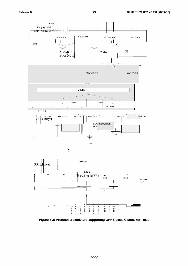
8/3/2019 3GPP TS 24007-V8.2.0
http://slidepdf.com/reader/full/3gpp-ts-24007-v820 23/149
3GPP
3GPP TS 24.007 V8.2.0 (2009-06)23Release 8
PDP
LLC-sublayer
RR-sublayer
MM-sublayer
GRR-SAP
P
R
A
C
H
P
P
C
H
P
A
G
C
H
P
B
C
C
H
P
D
T
C
H
P
A
C
C
H
SAPI
QoS1-SAPQoS2-SAPQoS3-SAPQoS4-SAP
GSMS
MNSMS-SAP
GRR
(shared mode RR)
LLSMS-SAP
LLC managemententity
LLGMM-SAP
GMMSM-SAP
GMMRR-
SAP
SESSION
MANAGEMENT
R
A
C
H
P
C
H
A
G
C
H
B
C
C
H
P
N
C
H
TI
GMMREG-SAP
CM
PD / TLLI
GMM
SNSM-SAP SMREG-SAP
SN-SAP
services (SNDCP)
User payload
SS
MNSS-SAP
TI
GMMSS-SAP
Figure 5.2: Protocol architecture supporting GPRS class C MSs, MS - side
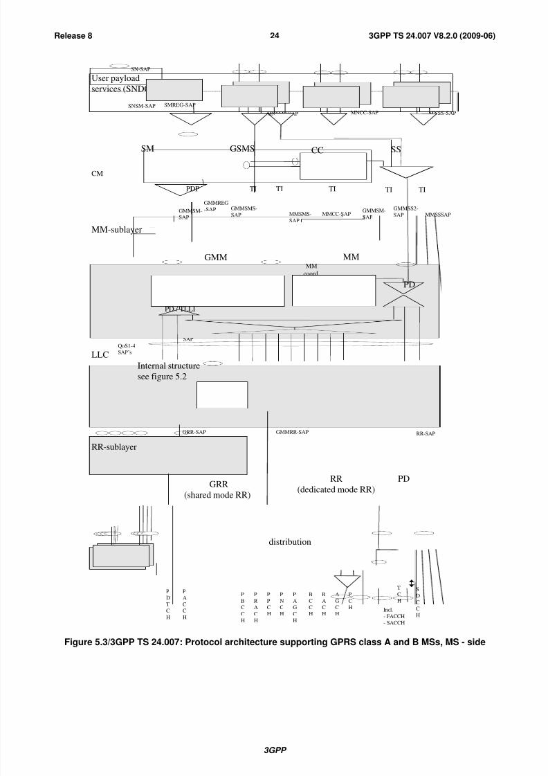
8/3/2019 3GPP TS 24007-V8.2.0
http://slidepdf.com/reader/full/3gpp-ts-24007-v820 24/149
3GPP
3GPP TS 24.007 V8.2.0 (2009-06)24Release 8
GMMSM-
SAP
LLC
sublayer
MM-sublayer
QoS1-4
SAP’s
User payload
services (SNDCP)
SN-SAP
GMM
GMM
coord
MNSMS-SAP
GMMREG
-SAP
LLGMM-
SAP
MMSMS-
SAP
MMCC-SAP MMSSSAP
LLSMS-SAP
MNSS-SAPMNCC-SAP
GMMSMS-
SAP
TITIPDP TI
CM
CC SSGSMS
TI
PD / TLLI
RR-SAPGRR-SAP
RR-sublayer
GMMRR-SAP
GRR
(shared mode RR)
P
D
T
C
H
P
A
C
C
H
P
R
A
C
H
P
P
C
H
P
A
G
C
H
P
B
C
C
H
R
A
C
H
P
C
H
A
G
C
H
B
C
C
H
P
N
C
H
T
C
H
S
D
C
C
H
PD
distribution
RR
(dedicated mode RR)
MMMM
coord PD
SNSM-SAP SMREG-SAP
SM
Internal structure
see figure 5.2
Incl.
- FACCH
- SACCH
GMMSS2-
SAPGMMSM-
SAP
TI
Figure 5.3/3GPP TS 24.007: Protocol architecture supporting GPRS class A and B MSs, MS - side
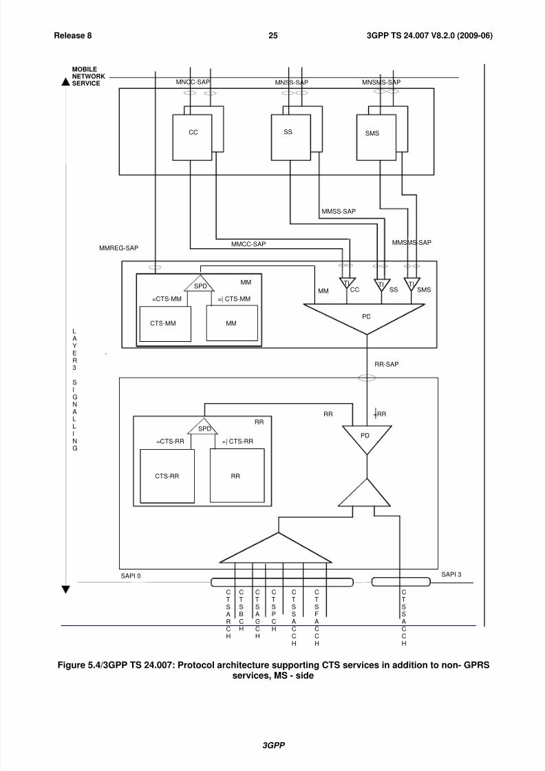
8/3/2019 3GPP TS 24007-V8.2.0
http://slidepdf.com/reader/full/3gpp-ts-24007-v820 25/149
3GPP
3GPP TS 24.007 V8.2.0 (2009-06)25Release 8
CTSARCH
CTSAGCH
CTSSACCH
CTSFACCH
SAPI 0 SAPI 3
RR
MM
PD
MM CC SS SMS
MMREG-SAPMMCC-SAP
MMSS-SAP
MMSMS-SAP
CC SS SMS
MOBILE
NETWORK
SERVICE MNCC-SAP MNSS-SAP MNSMS-SAP
CTSBCH
CTSPCH
CTSSACCH
RR-SAP
RR
LAYER3
SIG
NALLING
=RR
TI TI TI
PD
SPD
=CTS-RR =| CTS-RR
CTS-RR RR
SPD
=CTS-MM =| CTS-MM
CTS-MM MM
Figure 5.4/3GPP TS 24.007: Protocol architecture supporting CTS services in addition to non- GPRS
services, MS - side
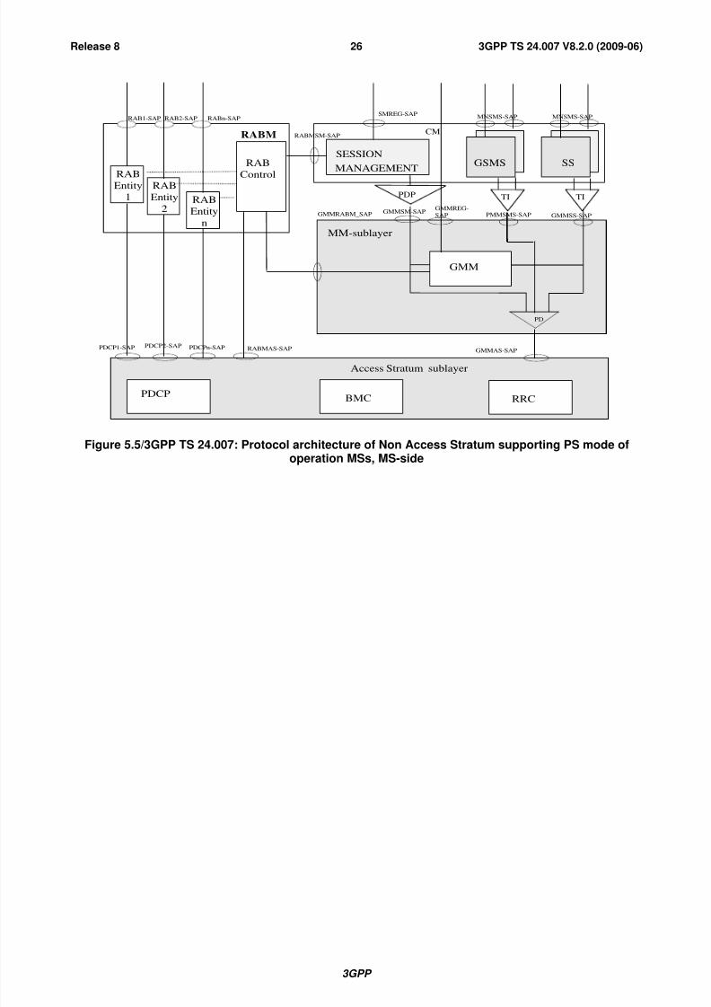
8/3/2019 3GPP TS 24007-V8.2.0
http://slidepdf.com/reader/full/3gpp-ts-24007-v820 26/149
3GPP
3GPP TS 24.007 V8.2.0 (2009-06)26Release 8
MM-sublayer
GSMS
MNSMS-SAP
PMMSMS-SAPGMMSM-SAP
SESSION
MANAGEMENT
TI
GMMREG-
SAP
CM
PD
GMM
SMREG-SAP
Access Stratum sublayer
RABMAS-SAPGMMAS-SAP
RRCPDCP
RABMSM-SAP
PDCPn-SAP
GMMRABM_SAP
BMC
PDCP2-SAPPDCP1-SAP
PDP
RABM
RAB1-SAP
RABEntity
1
RAB
Entity
2RAB
Entity
n
RAB
Control
RABn-SAPRAB2-SAP
SS
MNSMS-SAP
GMMSS-SAP
TI
Figure 5.5/3GPP TS 24.007: Protocol architecture of Non Access Stratum supporting PS mode ofoperation MSs, MS-side

8/3/2019 3GPP TS 24007-V8.2.0
http://slidepdf.com/reader/full/3gpp-ts-24007-v820 27/149
3GPP
3GPP TS 24.007 V8.2.0 (2009-06)27Release 8
GMMSM-
SAP
MM-sublayer
GMM
GMM
coord
MNSMS-SAP
GMMREG
-SAP MMSMS-
SAP
MMCC-SAP MMSSSAP
PMMSMS
-SAP
MNSS-SAPMNCC-SAP
GMMSMS-
SAP
TITIPDP TI
CM
CC SSGSMS
TI
PD
MMMM
coord PD
SMREG-SAP
R A B M S M - S A P
RABM
RAB1-SAP
RAB
Entity
1
RAB
Entity
2RAB
Entity
n
RAB
Control
RABn-SAPRAB2-SAP
SM
G
M M R A B M - S A P
Access Stratum sublayer
RABMAS-SAP GMMAS-SAP
RRCPDCP
PDCPn-SAP
BMC
PDCP2-SAPPDCP1-SAP RR-SAP
GMMSSSAP
TI
GMMSS2SAP
Figure 5.6/24.007: Protocol architecture of Non Access Stratum supporting CS/PS mode of operationMSs, MS – side
NOTE: SMS un-related parts of this figure, e.g. SNDCP should be modified for UMTS.

8/3/2019 3GPP TS 24007-V8.2.0
http://slidepdf.com/reader/full/3gpp-ts-24007-v820 28/149
3GPP
3GPP TS 24.007 V8.2.0 (2009-06)28Release 8
EMMESM-SAP
CM
RRCPDCP
E-UTRAN Access Stratum sublayer
EMMAS-SAP
RB 1
Bearer
ControlRB 2
RB n
PDCP1-SAP
EMM
PDCP2-SAP PDCP3-SAP
RB1-SAP RB2-SAP RBn-SAP
RBMAS-SAP
ESM
EMMREG-SAP
ESMREG-SAP
PD
MM Sublayer
EBI
Figure 5.7/3GPP TS 24.007: Protocol architecture of Non Access Stratum supporting PS mode ofoperation MSs, MS-side
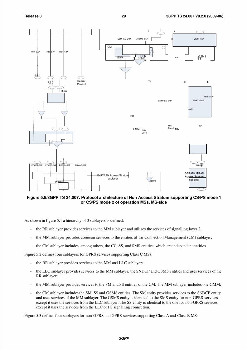
8/3/2019 3GPP TS 24007-V8.2.0
http://slidepdf.com/reader/full/3gpp-ts-24007-v820 29/149
3GPP
3GPP TS 24.007 V8.2.0 (2009-06)29Release 8
EBI
EMMESM-SAP
CM
MM-sublayer
RRCPDCP
E-UTRANAccessStratum
sublayer
EMMAS-SAP
GSMSESMS
EMMSMS-SAP
TI
RB1
Bearer
ControlRB2
RBn
PDCP1-SAP
EMMEMMCoord
MM
MM
Coord
PDCP2-SAP PDCPn-SAP
R B1 -S AP R B2 -S AP R Bn -S AP
RBMAS-SAP
ESM
EMMREG-SAP
ESMREG-SAP MNSMS-SAP
GSMSCC
MNCC-SAP
GSMSSS
MNSS-SAP
PD
TI
RR-SAP
MMCC-SAP
TI
MMSS-SAP
GERAN/UTRAN
AccessStratum
sublayer
PD
Figure 5.8/3GPP TS 24.007: Protocol architecture of Non Access Stratum supporting CS/PS mode 1or CS/PS mode 2 of operation MSs, MS-side
As shown in figure 5.1 a hierarchy of 3 sublayers is defined:
- the RR sublayer provides services to the MM sublayer and utilizes the services of signalling layer 2;
- the MM sublayer provides common services to the entities of the Connection Management (CM) sublayer;
- the CM sublayer includes, among others, the CC, SS, and SMS entities, which are independent entities.
Figure 5.2 defines four sublayers for GPRS services supporting Class C MSs:
- the RR sublayer provides services to the MM and LLC sublayers;
- the LLC sublayer provides services to the MM sublayer, the SNDCP and GSMS entities and uses services of the
RR sublayer;
- the MM sublayer provides services to the SM and SS entities of the CM. The MM sublayer includes one GMM;
- the CM sublayer includes the SM, SS and GSMS entities. The SM entity provides services to the SNDCP entity
and uses services of the MM sublayer. The GSMS entity is identical to the SMS entity for non-GPRS services
except it uses the services from the LLC sublayer. The SS entity is identical to the one for non-GPRS services
except it uses the services from the LLC or PS signalling connection.
Figure 5.3 defines four sublayers for non-GPRS and GPRS-services supporting Class A and Class B MSs:
8/3/2019 3GPP TS 24007-V8.2.0
http://slidepdf.com/reader/full/3gpp-ts-24007-v820 30/149
3GPP
3GPP TS 24.007 V8.2.0 (2009-06)30Release 8
- the RR sublayer provides services to the MM and LLC sublayers;
- the LLC sublayer provides services to the MM sublayer, the SNDCP and GSMS entities and uses services of theRR sublayer;
- the MM sublayer provides services to the SNDCP entity and to the entities of the Connection Management (CM)
sublayer. In addition to the MM entity for non-GPRS services, the MM sublayer further includes one GMM
entity;
- the CM sublayer includes, among others, the CC, SS, GSMS and SM entities, which are independent entities;
- the SM entity provides services to the SNDCP entity and uses services of the MM sublayer.The GSMS entity is an extension of the SMS entity for non-GPRS services. For message transfer it uses the
services both from the LLC sublayer and the MM entity of the MM sublayer. Furthermore it retrieves from the
MM entity information about which transport service to use.
Figure 5.4 defines three sub-layers for CTS services:
- the RR sublayer provides services (including CTS services) to the MM sublayer and uses the services of
signalling layer 2;
- the MM sublayer provides common services to the entities of the Connection Management (CM) sublayer; itprovides also specific CTS services to the entities above CM;
- the CM sublayer includes, among others, the CC, SS, and SMS entities, which are independent entities.
Figure 5.5 defines three sublayers for UMTS PS domain services supporting PS mode of operation:
- the Access Stratum (AS) sublayer provides services to the MM sublayer and the RAB Manager (RABM) entity.
- the MM sublayer provides services to the SM, SS and GSMS entities of the CM. The MM sublayer includesone GMM entity;
- the CM sublayer includes the SM, SS and GSMS entities. The SM entity provides services to the RABM entity
and uses services of the MM sublayer. The GSMS entity is identical to the SMS entity for GPRS services in
GSM except it uses the services from the GMM sublayer. The SS entity is identical to the one for non-GPRSservices except it uses the services from the LLC or PS signalling connection;
- the RABM hides the concepts of RABs that can be activated/released while a PDP context is active. If UL data
in the terminal is to be sent on a RAB (NSAPI) that has been released the RABM will trigger a service request
procedure in GMM.
Figure 5.6 defines three sublayers for UMTS CS domain services and UMTS PS domain services supporting CS/PS
mode of operation MSs:
- the Access Stratum (AS) sublayer provides services to the MM sublayer and the RAB Manager (RABM) entity;
- the MM sublayer provides services to the entities of the Connection Management (CM) sublayer. In addition to
the MM entity for CS domain services, the MM sublayer further includes one GMM entity;
- the CM sublayer includes, among others, the CC, SS, GSMS and SM entities, which are independent entities;
- the SM entity provides services to the RABM entity and uses services of the MM sublayer.
The GSMS entity is an extension of the SMS entity for CS domain services. For message transfer it uses the
services both from the GMM entity of the MM sublayer and the MM entity of the MM sublayer. Furthermore it
retrieves from the MM entity information about which transport service to use;
- the RABM hides the concepts of RABs that can be activated/released while a PDP context is active. If UL data
in the terminal is to be sent on a RAB (NSAPI) that has been released, the RABM will trigger a service request
procedure in GMM.
Figure 5.7 defines three sublayers for EPS PS domain services:
- the Access Stratum (AS) sublayer provides services to the MM sublayer;

8/3/2019 3GPP TS 24007-V8.2.0
http://slidepdf.com/reader/full/3gpp-ts-24007-v820 31/149
3GPP
3GPP TS 24.007 V8.2.0 (2009-06)31Release 8
- the MM sublayer provides services to the entities of the Connection Management (CM) sublayer. The MM
sublayer further includes one EMM entity;
- the CM sublayer includes ESM entities;
- the ESM entity provides services to the Bearer Control (BC) entity and uses services of the MM sublayer;
- the BC entity hides the concepts of radio bearers that can be established/released while an EPS bearer context isactive. If uplink data in the terminal is to be sent, and EPS bearers have been released, the BC will trigger a
service request procedure in EMM.
Figure 5.8 defines three sublayers for EPS domain services and non-EPS domain services supporting CS/PS mode 1 orCS/PS mode 2 of operation MSs:
- the Access Stratum (AS) sublayer provides services to the MM sublayer;
- the MM sublayer provides services to the entities of the Connection Management (CM) sublayer. In addition to
the MM entity for non-EPS services, the MM sublayer further includes one EMM entity;
- the CM sublayer includes among others, the CC, SS, ESMS and ESM entities, which are independent entities;
- the ESM entity provides services to the Bearer Control (BC) entity and uses services of the MM sublayer.The ESMS entity is an extension of the SMS entity for non-EPS services. For message transfer, it uses the
services from the EMM entity of the MM sublayer;
- the BC entity hides the concepts of radio bearers that can be established/released while an EPS bearer context is
active. If uplink data in the MS is to be sent, and all EPS bearers have been released, the BC will trigger a
service request procedure in EMM.
6 Services provided by signalling layer 3 at the MSside
The different classes of services provided by signalling layer 3 at the MS side are accessible at the following service
access points:
- registration services at the MMREG-SAP or GMMREG-SAP;
- Call Control services for normal and emergency calls including call related Supplementary Services Support
services at the MNCC-SAP;
- Short Message Services Support services at the MNSMS-SAP;
- Call independent Supplementary Services Support services at the MNSS-SAP;
- Location Services Support services at the MNLCS-SAP;
- other services corresponding to further functional blocks of the CM sublayer at the appropriate service accesspoints. These services are not further described in this clause;
- Session Management services at the SMREG-SAP and at the SNSM-SAP;
- Logical Link Control services at the QoS1-SAP, QoS2-SAP, QoS3-SAP and QoS4-SAP.
6.1 Registration services
The registration services (location updating, IMSI attach/detach) are provided at the service access point
MMREG-SAP. As opposed to all other MN-Services, these services are provided by and can be directly accessed at the
Mobility Management sublayer.
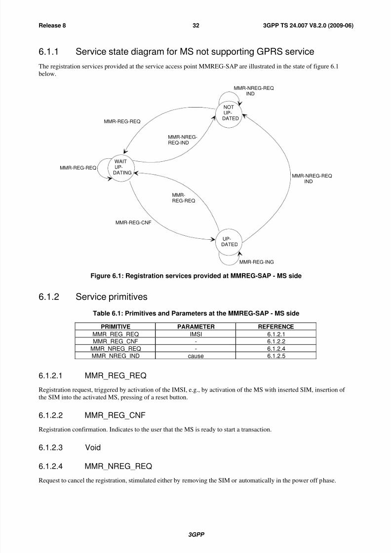
8/3/2019 3GPP TS 24007-V8.2.0
http://slidepdf.com/reader/full/3gpp-ts-24007-v820 32/149
3GPP
3GPP TS 24.007 V8.2.0 (2009-06)32Release 8
6.1.1 Service state diagram for MS not supporting GPRS service
The registration services provided at the service access point MMREG-SAP are illustrated in the state of figure 6.1
below.
MMR-NREG-REQIND
MMR-NREG-REQIND
MMR-REG-ING
UP-DATED
NOTUP-
DATED
WAITUP-
DATING
MMR-REG-CNF
MMR-REG-REQ
MMR-REG-REQ
MMR-REG-REQ
MMR-NREG-REQ-IND
Figure 6.1: Registration services provided at MMREG-SAP - MS side
6.1.2 Service primitives
Table 6.1: Primitives and Parameters at the MMREG-SAP - MS side
PRIMITIVE PARAMETER REFERENCE
MMR_REG_REQ IMSI 6.1.2.1
MMR_REG_CNF - 6.1.2.2
MMR_NREG_REQ - 6.1.2.4
MMR_NREG_IND cause 6.1.2.5
6.1.2.1 MMR_REG_REQ
Registration request, triggered by activation of the IMSI, e.g., by activation of the MS with inserted SIM, insertion of the SIM into the activated MS, pressing of a reset button.
6.1.2.2 MMR_REG_CNF
Registration confirmation. Indicates to the user that the MS is ready to start a transaction.
6.1.2.3 Void
6.1.2.4 MMR_NREG_REQ
Request to cancel the registration, stimulated either by removing the SIM or automatically in the power off phase.
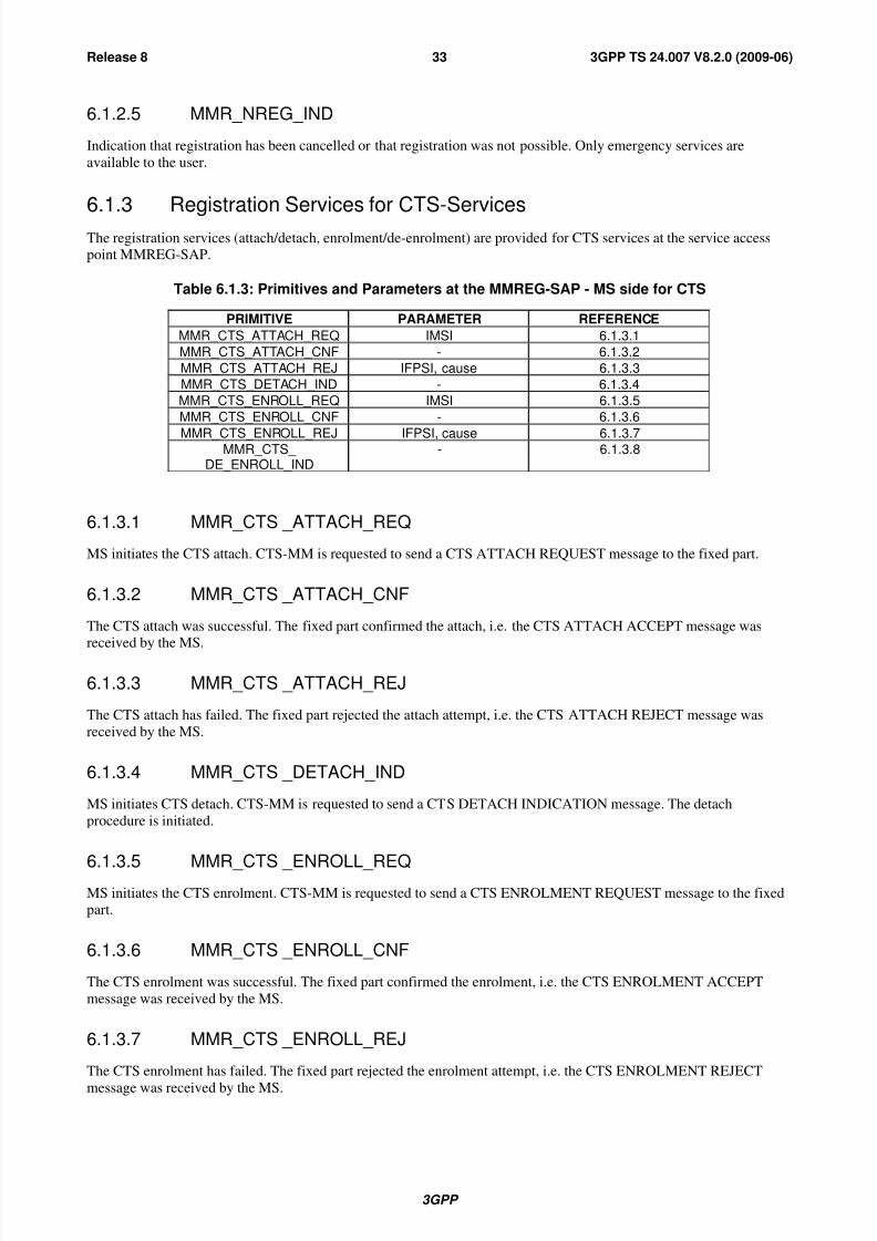
8/3/2019 3GPP TS 24007-V8.2.0
http://slidepdf.com/reader/full/3gpp-ts-24007-v820 33/149
3GPP
3GPP TS 24.007 V8.2.0 (2009-06)33Release 8
6.1.2.5 MMR_NREG_IND
Indication that registration has been cancelled or that registration was not possible. Only emergency services are
available to the user.
6.1.3 Registration Services for CTS-Services
The registration services (attach/detach, enrolment/de-enrolment) are provided for CTS services at the service accesspoint MMREG-SAP.
Table 6.1.3: Primitives and Parameters at the MMREG-SAP - MS side for CTS
PRIMITIVE PARAMETER REFERENCE
MMR_CTS_ATTACH_REQ IMSI 6.1.3.1
MMR_CTS_ATTACH_CNF - 6.1.3.2
MMR_CTS_ATTACH_REJ IFPSI, cause 6.1.3.3
MMR_CTS_DETACH_IND - 6.1.3.4
MMR_CTS_ENROLL_REQ IMSI 6.1.3.5
MMR_CTS_ENROLL_CNF - 6.1.3.6
MMR_CTS_ENROLL_REJ IFPSI, cause 6.1.3.7MMR_CTS_
DE_ENROLL_IND- 6.1.3.8
6.1.3.1 MMR_CTS _ATTACH_REQ
MS initiates the CTS attach. CTS-MM is requested to send a CTS ATTACH REQUEST message to the fixed part.
6.1.3.2 MMR_CTS _ATTACH_CNF
The CTS attach was successful. The fixed part confirmed the attach, i.e. the CTS ATTACH ACCEPT message wasreceived by the MS.
6.1.3.3 MMR_CTS _ATTACH_REJ
The CTS attach has failed. The fixed part rejected the attach attempt, i.e. the CTS ATTACH REJECT message was
received by the MS.
6.1.3.4 MMR_CTS _DETACH_IND
MS initiates CTS detach. CTS-MM is requested to send a CTS DETACH INDICATION message. The detach
procedure is initiated.
6.1.3.5 MMR_CTS _ENROLL_REQMS initiates the CTS enrolment. CTS-MM is requested to send a CTS ENROLMENT REQUEST message to the fixedpart.
6.1.3.6 MMR_CTS _ENROLL_CNF
The CTS enrolment was successful. The fixed part confirmed the enrolment, i.e. the CTS ENROLMENT ACCEPT
message was received by the MS.
6.1.3.7 MMR_CTS _ENROLL_REJ
The CTS enrolment has failed. The fixed part rejected the enrolment attempt, i.e. the CTS ENROLMENT REJECT
message was received by the MS.

8/3/2019 3GPP TS 24007-V8.2.0
http://slidepdf.com/reader/full/3gpp-ts-24007-v820 34/149
3GPP
3GPP TS 24.007 V8.2.0 (2009-06)34Release 8
6.1.3.8 MMR_CTS _DE_ENROLL_IND
FP initiates CTS de-enrolment. CTS-MM is requested to send a CTS DE-ENROLMENT INDICATION message. The
de-enrolment procedure is initiated.
6.2 Call Control servicesThe Call Control services are provided by multiple CC entities at the service access point MNCC-SAP.
The Call Control service class consists of the following services:
- Mobile originated and Mobile terminated call establishment for normal calls;
- Mobile originated call establishment for emergency calls;
- call maintaining;
- call termination;
- call related Supplementary Services Support.
6.2.1 Service state diagram
The Call Control services provided at the service access point MNCC-SAP are illustrated in the state diagram of
figure 6.2.

8/3/2019 3GPP TS 24007-V8.2.0
http://slidepdf.com/reader/full/3gpp-ts-24007-v820 35/149
3GPP
3GPP TS 24.007 V8.2.0 (2009-06)35Release 8
RELEASE
REQUEST
DISONNECT
INDICATION
STATES
3,4,7,8,9,10
DISCONNECT
REQUEST
CALL INIT
NO CALL
PROCEEDING
RELEASE
REQUEST
CALLDELIVERED
ACTIVE
CALL
RECEIVED
CONNECT
REQUEST
MT CALL
CONFIRMED
CALL
PRESENT
NULL0
1
3
419
10
19
12
6
9
7
8
11
MNCC-SETUP-IND
MNCC-REJ-REQ
MNCC-REL-
REQMNCC-
DISC-
IND
MNCC-
REL-
IND
MNCC-REJ-IND
MNCC-SETUP-REQ
MNCC-DISC-
REQ
MNCC-
DISC-
IND
MNCC-CAL
CONF-REQ
MNCC-
SETUP-
RSP
MNCC-
ALERT-
REQ
MNCC-
SETUP-RSP
MNCC-SETUP-
COMPL-IND (ERR)
MNCC-
DISC-
IND
MNCC-
DISC-
REQ
MNCC-SETUP-COMP-INDMNCC-SETUP-
CNF
MNCC-
SETUP-
CNF
MNCC-
ALERT-
IND
MNCC-REL-
REQ
MNCC-
PROGRESS-
IND
MNCC-CALL
PROC-IND
MNCC-
REL-
CNF
MNCC-
FACILITY-
IND
ANY STATE
EXCEPT 0ANY STATE MNCC-
REL-
IND
0ANY STATE
EXCEPT 0,19MNCC-
FACILITY
REQ
Figure 6.2: Service graph of Call Control entity - MS side (page 1 of 2)

8/3/2019 3GPP TS 24007-V8.2.0
http://slidepdf.com/reader/full/3gpp-ts-24007-v820 36/149
3GPP
3GPP TS 24.007 V8.2.0 (2009-06)36Release 8
10 ACTIVE
28 M0
MODIFY
MNCC-MODIFY-CNFMNCC-MODIFY-REQ
MNCC-DTMF-START-REQ
CNFMNCC-DTMF-STOP-REQ
CNF
MNCC-SYNC-IND (res ass)MNCC-SYNC-IND (channel mode
modify)MNCC-NOTIFY-REQ
INDMNCC-MODIFY-IND
MNCC-SYNC-IND (res ass)MNCC-SYNC-IND (channel mode
modify)
Figure 6.2: Service graph of Call Control entity - MS side Active state (page 2 of 2)
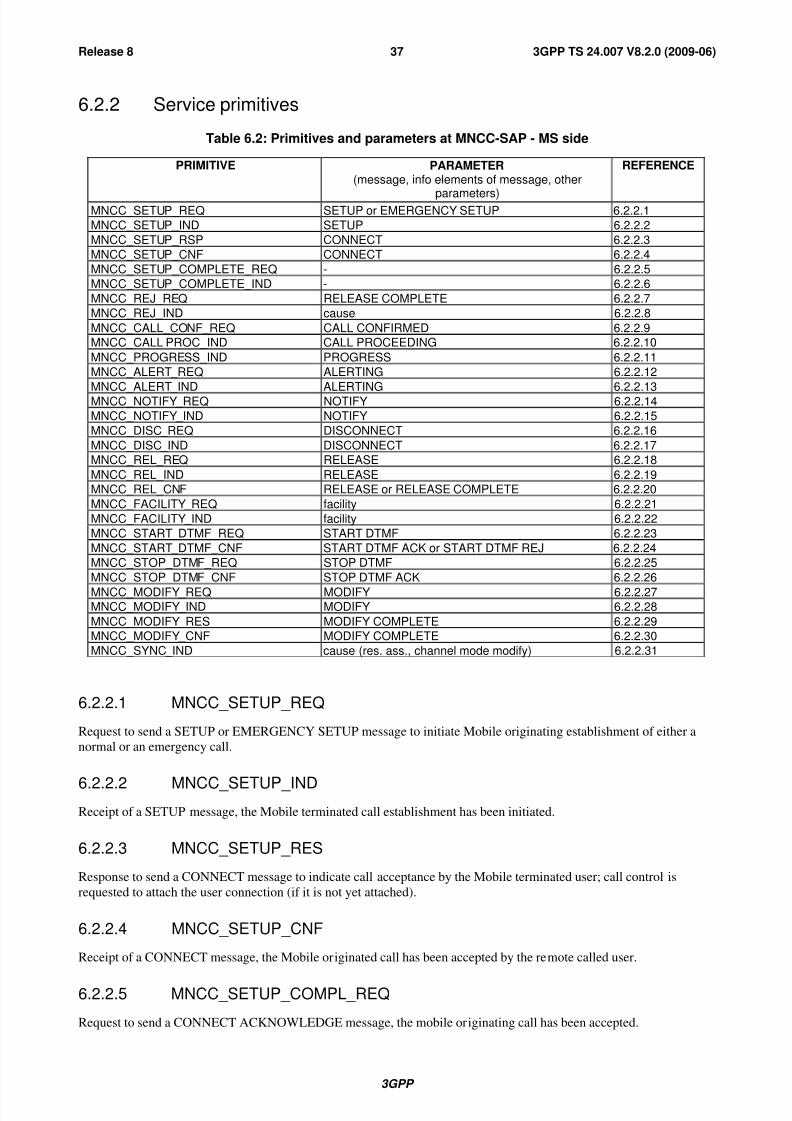
8/3/2019 3GPP TS 24007-V8.2.0
http://slidepdf.com/reader/full/3gpp-ts-24007-v820 37/149
3GPP
3GPP TS 24.007 V8.2.0 (2009-06)37Release 8
6.2.2 Service primitives
Table 6.2: Primitives and parameters at MNCC-SAP - MS side
PRIMITIVE PARAMETER(message, info elements of message, other
parameters)
REFERENCE
MNCC_SETUP_REQ SETUP or EMERGENCY SETUP 6.2.2.1
MNCC_SETUP_IND SETUP 6.2.2.2
MNCC_SETUP_RSP CONNECT 6.2.2.3
MNCC_SETUP_CNF CONNECT 6.2.2.4
MNCC_SETUP_COMPLETE_REQ - 6.2.2.5
MNCC_SETUP_COMPLETE_IND - 6.2.2.6
MNCC_REJ_REQ RELEASE COMPLETE 6.2.2.7
MNCC_REJ_IND cause 6.2.2.8
MNCC_CALL_CONF_REQ CALL CONFIRMED 6.2.2.9
MNCC_CALL PROC_IND CALL PROCEEDING 6.2.2.10
MNCC_PROGRESS_IND PROGRESS 6.2.2.11
MNCC_ALERT_REQ ALERTING 6.2.2.12
MNCC_ALERT_IND ALERTING 6.2.2.13MNCC_NOTIFY_REQ NOTIFY 6.2.2.14
MNCC_NOTIFY_IND NOTIFY 6.2.2.15
MNCC_DISC_REQ DISCONNECT 6.2.2.16
MNCC_DISC_IND DISCONNECT 6.2.2.17
MNCC_REL_REQ RELEASE 6.2.2.18
MNCC_REL_IND RELEASE 6.2.2.19
MNCC_REL_CNF RELEASE or RELEASE COMPLETE 6.2.2.20
MNCC_FACILITY_REQ facility 6.2.2.21
MNCC_FACILITY_IND facility 6.2.2.22
MNCC_START_DTMF_REQ START DTMF 6.2.2.23
MNCC_START_DTMF_CNF START DTMF ACK or START DTMF REJ 6.2.2.24
MNCC_STOP_DTMF_REQ STOP DTMF 6.2.2.25
MNCC_STOP_DTMF_CNF STOP DTMF ACK 6.2.2.26
MNCC_MODIFY_REQ MODIFY 6.2.2.27MNCC_MODIFY_IND MODIFY 6.2.2.28
MNCC_MODIFY_RES MODIFY COMPLETE 6.2.2.29
MNCC_MODIFY_CNF MODIFY COMPLETE 6.2.2.30
MNCC_SYNC_IND cause (res. ass., channel mode modify) 6.2.2.31
6.2.2.1 MNCC_SETUP_REQ
Request to send a SETUP or EMERGENCY SETUP message to initiate Mobile originating establishment of either a
normal or an emergency call.
6.2.2.2 MNCC_SETUP_INDReceipt of a SETUP message, the Mobile terminated call establishment has been initiated.
6.2.2.3 MNCC_SETUP_RES
Response to send a CONNECT message to indicate call acceptance by the Mobile terminated user; call control is
requested to attach the user connection (if it is not yet attached).
6.2.2.4 MNCC_SETUP_CNF
Receipt of a CONNECT message, the Mobile originated call has been accepted by the remote called user.
6.2.2.5 MNCC_SETUP_COMPL_REQ
Request to send a CONNECT ACKNOWLEDGE message, the mobile originating call has been accepted.
8/3/2019 3GPP TS 24007-V8.2.0
http://slidepdf.com/reader/full/3gpp-ts-24007-v820 38/149
3GPP
3GPP TS 24.007 V8.2.0 (2009-06)38Release 8
6.2.2.6 MNCC_SETUP_COMPL_IND
Receipt of a CONNECT ACKNOWLEDGE message, the Mobile terminated call establishment has been completed; for
a data call, the user is informed that the user connection is attached.
6.2.2.7 MNCC_REJ_REQ
Request to reject a Mobile terminated call if the call is refused or if the call cannot be accepted, e.g., because of missing
compatibility.
6.2.2.8 MNCC_REJ_IND
Indication that the Mobile originated call has been rejected, e.g. if the MM connection cannot be provided or if the call
establishment initiation has been rejected by the network.
6.2.2.9 MNCC_CALL_CONF_REQ
Request to confirm a Mobile terminated call by sending a CALL CONFIRMED message. A bearer capability different
from that given in MNCC_SETUP_IND may be offered to the remote calling user.
6.2.2.10 MNCC_CALL_PROC_IND
Indication to the Mobile originating user that call establishment has been initiated in the Network and no more call
establishment information will be accepted by the Network.
6.2.2.11 MNCC_PROGRESS_IND
Indication to the Mobile user that a PROGRESS message or a message containing a progress IE has been received, e.g.,
because the call is progressing in the PLMN/ISDN environment, or because the call has left the PLMN/ISDN
environment, or because in-band tones/announcement are available.
6.2.2.12 MNCC_ALERT_REQ
Request to send an ALERTING message from the called Mobile user to the remote calling user to indicate that user
alerting has been initiated.
6.2.2.13 MNCC_ALERT_IND
Indication of the receipt of an ALERTING message, alerting to the remote called user has been initiated.
6.2.2.14 MNCC_NOTIFY_REQ
Request to send information pertaining to a call, such as user suspended, to the Network by the Mobile user.
6.2.2.15 MNCC_NOTIFY_IND
Indication to the Mobile user that information pertaining to a call, such as remote user suspended, has been received
from the Network.
6.2.2.16 MNCC_DISC_REQ
Request to send a DISCONNECT message to the Network in order to clear the end-to-end connection.
6.2.2.17 MNCC_DISC_IND
Indication of reception of a DISCONNECT message, by which the Network indicates that the end-to-end connection iscleared.
8/3/2019 3GPP TS 24007-V8.2.0
http://slidepdf.com/reader/full/3gpp-ts-24007-v820 39/149
3GPP
3GPP TS 24.007 V8.2.0 (2009-06)39Release 8
6.2.2.18 MNCC_REL_REQ
Request of the Mobile user to send a RELEASE message to inform the Network that the user intends to release the call
reference and the corresponding MM connection so that the Network can release its MM connection and the
correspondent call reference.
6.2.2.19 MNCC_REL_IND
Indication to the Mobile originating or terminated user that a RELEASE message has been received and the Network
intends to release its MM connection. The Mobile user is requested to release the call reference and the corresponding
MM connection.
6.2.2.20 MNCC_REL_CNF
Confirmation of the Mobile user's request to release the MM connection and call reference in the Network. The Mobile
user may release the call reference and the corresponding MM connection.
6.2.2.21 MNCC_FACILITY_REQ
Request to transport a facility IE for a call related supplementary service invocation.
6.2.2.22 MNCC_FACILITY_IND
Indication that a facility IE for a call related supplementary service invocation has been received.
6.2.2.23 MNCC_START_DTMF_REQ
Request to send a START DTMF message in order to start a DTMF control operation.
6.2.2.24 MNCC_START_DTMF_CNF
Confirmation of the receipt of a START DTMF ACKNOWLEDGE or START DTMF REJECT message that the start
of a DTMF control operation has been acknowledged or rejected.
6.2.2.25 MNCC_STOP_DTMF_REQ
Request to send a STOP DTMF message in order to stop a DTMF control operation.
6.2.2.26 MNCC_STOP_DTMF_CNF
Confirmation of the receipt of STOP DTMF ACKNOWLEDGE message, the DTMF control operation has been
stopped.
6.2.2.27 MNCC_MODIFY_REQ
Request to start Mobile originating in-call modification by sending a MODIFY message.
6.2.2.28 MNCC_MODIFY_IND
RECEIPT OF A MODIFY message, a Mobile terminating in-call modification has been initiated.
6.2.2.29 MNCC_MODIFY_RES
Response to send a MODIFY COMPLETE message to indicate Mobile terminating in-call modification completion bythe Mobile user.

8/3/2019 3GPP TS 24007-V8.2.0
http://slidepdf.com/reader/full/3gpp-ts-24007-v820 40/149
3GPP
3GPP TS 24.007 V8.2.0 (2009-06)40Release 8
6.2.2.30 MNCC_MODIFY_CNF
Receipt of a MODIFY COMPLETE message, the Mobile originating in-call modification has been completed.
6.2.2.31 MNCC_SYNC_IND
Indication that a dedicated channel assignment has been performed (res. ass. = "resource assigned") and/or the channelmode has been changed.
6.3 Call independent Supplementary Services Support
6.3.1 Service state diagram
The primitives provided by the call independent Supplementary Services Support entity and the transitions between
permitted states are shown in figure 6.3.
IDLE
CONN
MNSS-END-REQIND
MNSS-FACILITY-REQIND
MNSS-END-REQIND
MNSS-BEGIN-REQIND
STATES:IDLE - No SS signalling transaction pending.CONN - SS signalling transaction established.
Figure 6.3: Service graph of the call independent Supplementary Services Support entity - MS side
6.3.2 Service primitivesTable 6.3: Primitives and Parameters at MNSS-SAP - MS side
PRIMITIVES PARAMETERS(Info elements of message)
REFERENCE
MNSS_BEGIN_REQ REGISTER 6.3.2.1
MNSS_BEGIN_IND REGISTER 6.3.2.2
MNSS_FACILITY_REQ FACILITY 6.3.2.3
MNSS_FACILITY_IND FACILITY 6.3.2.4
MNSS_END_REQ REL COMPLETE 6.3.2.5
MNSS_END_IND REL COMPLETE 6.3.2.6

8/3/2019 3GPP TS 24007-V8.2.0
http://slidepdf.com/reader/full/3gpp-ts-24007-v820 41/149
3GPP
3GPP TS 24.007 V8.2.0 (2009-06)41Release 8
6.3.2.1 MNSS_BEGIN_REQ
Request to send a REGISTER message in order to establish a signalling transaction for the provision of call
independent supplementary services. The request for a call independent supplementary service invocation may be
included.
6.3.2.2 MNSS_BEGIN_IND
Receipt of a REGISTER message, a signalling transaction is established for the provision of call independent
supplementary services after receipt of a REGISTER message. The indication of a supplementary service invocation
may be included.
6.3.2.3 MNSS_FACILITY_REQ
Request to send a FACILITY message for the provision of a call independent supplementary service invocation.
6.3.2.4 MNSS_FACILITY_IND
Receipt of a FACILITY message for a call independent supplementary service invocation.
6.3.2.5 MNSS_END_REQ
Request to send a RELEASE COMPLETE message in order to release the signalling transaction. The request for
transfer of a supplementary service facility may be included.
6.3.2.6 MNSS_END_IND
Receipt of a RELEASE COMPLETE message, the signalling transaction has been released. The indication of a
supplementary service facility may be included.
6.4 Short Message Services SupportThe service provided by the CM sublayer to support the short message service are defined in
3GPP TS 24.011 [8].
6.5 Session Management Services for GPRS-Services
Session Management services are provided at the SMREG-SAP and the SNSM-SAP. The procedures for GPRS Session
Management (i.e. PDP context activation, PDP context deactivation and PDP context modification) and MBMS Session
Management (i.e. MBMS context activation and MBMS context deactivation) are available at the SMREG-SAP.
Before any user data transfer is initiated (eg.via SNDCP in GSM case), the PDP context activation procedure must be
performed. In case of MBMS, the MS must also perform the procedures needed in order to activate a multicast service.
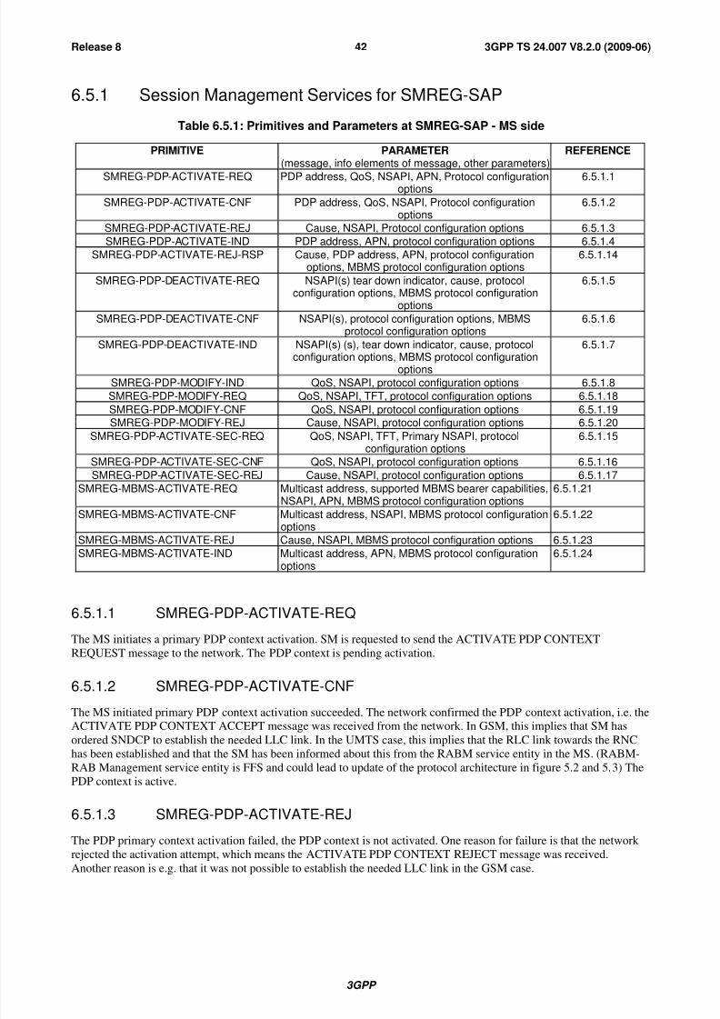
8/3/2019 3GPP TS 24007-V8.2.0
http://slidepdf.com/reader/full/3gpp-ts-24007-v820 42/149
3GPP
3GPP TS 24.007 V8.2.0 (2009-06)42Release 8
6.5.1 Session Management Services for SMREG-SAP
Table 6.5.1: Primitives and Parameters at SMREG-SAP - MS side
PRIMITIVE PARAMETER(message, info elements of message, other parameters)
REFERENCE
SMREG-PDP-ACTIVATE-REQ PDP address, QoS, NSAPI, APN, Protocol configurationoptions
6.5.1.1
SMREG-PDP-ACTIVATE-CNF PDP address, QoS, NSAPI, Protocol configurationoptions
6.5.1.2
SMREG-PDP-ACTIVATE-REJ Cause, NSAPI, Protocol configuration options 6.5.1.3
SMREG-PDP-ACTIVATE-IND PDP address, APN, protocol configuration options 6.5.1.4
SMREG-PDP-ACTIVATE-REJ-RSP Cause, PDP address, APN, protocol configurationoptions, MBMS protocol configuration options
6.5.1.14
SMREG-PDP-DEACTIVATE-REQ NSAPI(s) tear down indicator, cause, protocolconfiguration options, MBMS protocol configuration
options
6.5.1.5
SMREG-PDP-DEACTIVATE-CNF NSAPI(s), protocol configuration options, MBMSprotocol configuration options
6.5.1.6
SMREG-PDP-DEACTIVATE-IND NSAPI(s) (s), tear down indicator, cause, protocol
configuration options, MBMS protocol configurationoptions
6.5.1.7
SMREG-PDP-MODIFY-IND QoS, NSAPI, protocol configuration options 6.5.1.8
SMREG-PDP-MODIFY-REQ QoS, NSAPI, TFT, protocol configuration options 6.5.1.18
SMREG-PDP-MODIFY-CNF QoS, NSAPI, protocol configuration options 6.5.1.19
SMREG-PDP-MODIFY-REJ Cause, NSAPI, protocol configuration options 6.5.1.20
SMREG-PDP-ACTIVATE-SEC-REQ QoS, NSAPI, TFT, Primary NSAPI, protocolconfiguration options
6.5.1.15
SMREG-PDP-ACTIVATE-SEC-CNF QoS, NSAPI, protocol configuration options 6.5.1.16
SMREG-PDP-ACTIVATE-SEC-REJ Cause, NSAPI, protocol configuration options 6.5.1.17
SMREG-MBMS-ACTIVATE-REQ Multicast address, supported MBMS bearer capabilities,NSAPI, APN, MBMS protocol configuration options
6.5.1.21
SMREG-MBMS-ACTIVATE-CNF Multicast address, NSAPI, MBMS protocol configurationoptions
6.5.1.22
SMREG-MBMS-ACTIVATE-REJ Cause, NSAPI, MBMS protocol configuration options 6.5.1.23
SMREG-MBMS-ACTIVATE-IND Multicast address, APN, MBMS protocol configurationoptions
6.5.1.24
6.5.1.1 SMREG-PDP-ACTIVATE-REQ
The MS initiates a primary PDP context activation. SM is requested to send the ACTIVATE PDP CONTEXT
REQUEST message to the network. The PDP context is pending activation.
6.5.1.2 SMREG-PDP-ACTIVATE-CNF
The MS initiated primary PDP context activation succeeded. The network confirmed the PDP context activation, i.e. theACTIVATE PDP CONTEXT ACCEPT message was received from the network. In GSM, this implies that SM has
ordered SNDCP to establish the needed LLC link. In the UMTS case, this implies that the RLC link towards the RNC
has been established and that the SM has been informed about this from the RABM service entity in the MS. (RABM-
RAB Management service entity is FFS and could lead to update of the protocol architecture in figure 5.2 and 5.3) The
PDP context is active.
6.5.1.3 SMREG-PDP-ACTIVATE-REJ
The PDP primary context activation failed, the PDP context is not activated. One reason for failure is that the network
rejected the activation attempt, which means the ACTIVATE PDP CONTEXT REJECT message was received.
Another reason is e.g. that it was not possible to establish the needed LLC link in the GSM case.

8/3/2019 3GPP TS 24007-V8.2.0
http://slidepdf.com/reader/full/3gpp-ts-24007-v820 43/149
3GPP
3GPP TS 24.007 V8.2.0 (2009-06)43Release 8
6.5.1.4 SMREG-PDP-ACTIVATE-IND
The network asked for a PDP context activation. The REQUEST PDP CONTEXT ACTIVATION message was
received from the network. The MS reacts either by initiating a new primary PDP context activation or by rejecting the
network's request.
6.5.1.5 SMREG-PDP-DEACTIVATE-REQ
The MS initiates a PDP context deactivation: SM is requested to send a DEACTIVATE PDP CONTEXT REQUEST
message to the network. The PDP context is pending deactivation. Presence of the teardown indicator will lead to
deactivation of all PDP contexts coupled to the identified PDP address. NSAPI(s) to be deallocated from the SNDCP
entity via the SNSM-SAP for the GSM case, are included in the primitive.
6.5.1.6 SMREG-PDP-DEACTIVATE-CNF
The MS initiated PDP context deactivation has been done. The network confirmed the PDP context deactivation, i.e. theDEACTIVATE PDP CONTEXT ACCEPT message was received from the network. For GSM SM has ordered SNDCP
to locally release not further needed LLC links. In the UMTS case, the release of the RLC link towards the RNC takes
place as a result of a RAB release trigger from the network side. SM has been informed about this from the RABM
service entity in the MS. (RABM- RAB Management service entity is FFS and could lead to update of the protocol
architecture in figure 5.2 and 5.3.) The PDP context has been deactivated.
6.5.1.7 SMREG-PDP-DEACTIVATE-IND
A network initiated PDP context deactivation has been performed. The DEACTIVATE PDP CONTEXT REQUESTmessage has been received from the network. The MS has acknowledged with the DEACTIVATE PDP CONTEXT
ACCEPT message. The PDP context has been deactivated, the related LLC links in GSM or RLC links in UMTS were
locally released. Presence of the teardown indicator will lead to deactivation of all PDP contexts coupled to the
identified PDP address. NSAPI is included in the primitive to allow identification of the PDP context(s) needing
deactivation.
6.5.1.8 SMREG-PDP-MODIFY-IND
A network initiated PDP context modification has been performed. The MODIFY PDP CONTEXT REQUEST message has been received from the network. The modification has been acknowledged by sending the MODIFY PDP
CONTEXT ACCEPT message. One PDP context has been modified. LLC links is adjusted.
6.5.1.9 Void
6.5.1.10 Void
6.5.1.11 Void
6.5.1.12 Void
6.5.1.13 Void
6.5.1.14 SMREG-PDP-ACTIVATE-REJ-RSP
The network requested PDP context activation failed.
6.5.1.15 SMREG-PDP-ACTIVATE-SEC-REQ
The MS initiates a secondary PDP context activation. SM is requested to send the ACTIVATE SECONDARY PDP
CONTEXT REQUEST message to the network. The PDP context is pending activation.
8/3/2019 3GPP TS 24007-V8.2.0
http://slidepdf.com/reader/full/3gpp-ts-24007-v820 44/149
3GPP
3GPP TS 24.007 V8.2.0 (2009-06)44Release 8
6.5.1.16 SMREG-PDP-ACTIVATE-SEC-CNF
The MS initiated secondary PDP context activation succeeded. The network confirmed the PDP context activation, i.e.
the ACTIVATE SECONDARY PDP CONTEXT ACCEPT message was received from the network. In GSM, this
implies that SM has ordered SNDCP to establish the needed LLC link. In the UMTS case, this implies that the RLC link
towards the RNC has been established and that the SM has been informed about this from the RABM service entity in
the MS. (RABM- RAB Management service entity is FFS and could lead to update of the protocol architecture infigure 5.2 and 5.3) The PDP context connected to the same PDP address as the PDP context identified by the primary
NSAPI parameter in SMREG-PDP-ACTIVATE-SEC-REQ is active. ('Primary NSAPI' will point to any one of the
other established PDP contexts for a given PDP address).
6.5.1.17 SMREG-PDP-ACTIVATE-SEC-REJ
The secondary PDP context activation failed, the PDP context is not activated. One reason for failure is that the network
rejected the activation attempt, which means the ACTIVATE SECONDARY PDP CONTEXT REJECT message was
received. Another reason is e.g. that it was not possible to establish the needed LLC link in the GSM case.
6.5.1.18 SMREG-PDP-MODIFY-REQ
An MS initiated PDP context modification is requested. The MODIFY PDP CONTEXT REQUEST message is sent to
the network and pending acceptance. Affected PDP context is identified via the NSAPI value included in the primitive.
6.5.1.19 SMREG-PDP-MODIFY-CNF
An MS initiated PDP context modification has been accepted by the network. The modification is acknowledged fromthe network via the MODIFY PDP CONTEXT ACCEPT message. The addressed PDP context has been modified. LLC
or RLC link is adjusted according to the QoS returned from the network.
6.5.1.20 SMREG-PDP-MODIFY-REJ
An MS initiated PDP context modification has been rejected by the network. The rejection is signalled from the
network via the MODIFY PDP CONTEXT REJECT message with the cause code. The PDP context remains activewithout change of QoS.
6.5.1.21 SMREG-MBMS-ACTIVATE-REQ
The MS initiates an MBMS context activation as requested by the network. SM is requested to send the ACTIVATE
MBMS CONTEXT REQUEST message to the network. The MBMS context is pending activation waiting for the
network confirmation.
6.5.1.22 SMREG-MBMS-ACTIVATE-CNF
The MBMS context activation succeeded. The network confirmed the MBMS context activation, i.e. the ACTIVATE
MBMS CONTEXT ACCEPT message was received from the network. The MBMS context is active.
6.5.1.23 SMREG-MBMS-ACTIVATE-REJ
The MBMS context activation failed, the MBMS context is not activated.
6.5.1.24 SMREG-MBMS-ACTIVATE-REJ-RSP
The network requested MBMS context activation failed. SM is requested to send the REQUEST MBMS CONTEXT
ACTIVATION REJECT message to the network.
6.5.1.25 SMREG-MBMS-ACTIVATE-IND
The network asked for an MBMS context activation. The REQUEST MBMS CONTEXT ACTIVATION message was
received from the network. The MS reacts either by initiating the activation of the MBMS context or by rejecting the
request from the network.
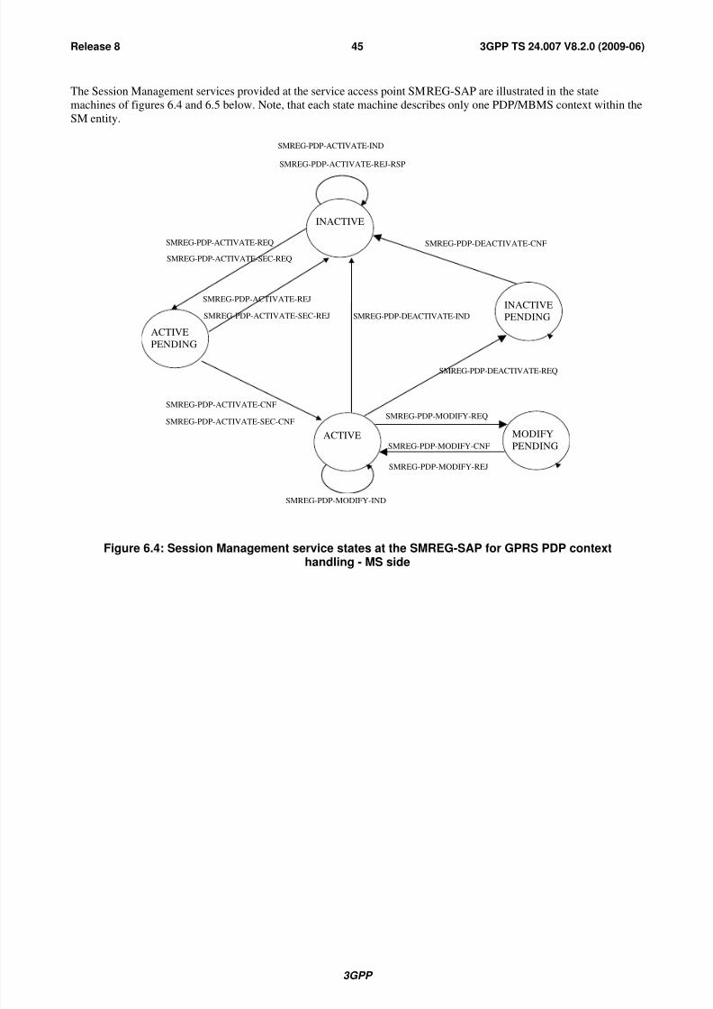
8/3/2019 3GPP TS 24007-V8.2.0
http://slidepdf.com/reader/full/3gpp-ts-24007-v820 45/149
3GPP
3GPP TS 24.007 V8.2.0 (2009-06)45Release 8
The Session Management services provided at the service access point SMREG-SAP are illustrated in the state
machines of figures 6.4 and 6.5 below. Note, that each state machine describes only one PDP/MBMS context within the
SM entity.
ACTIVE
SMREG-PDP-ACTIVATE-REQ
ACTIVE
PENDING
SMREG-PDP-ACTIVATE-CNF
INACTIVE
SMREG-PDP-MODIFY-IND
SMREG-PDP-DEACTIVATE-IND
MODIFY
PENDING
SMREG-PDP-MODIFY-REQ
SMREG-PDP-MODIFY-CNF
INACTIVE
PENDING
SMREG-PDP-DEACTIVATE-REQ
SMREG-PDP-DEACTIVATE-CNF
SMREG-PDP-ACTIVATE-SEC-REQ
SMREG-PDP-ACTIVATE-SEC-CNF
SMREG-PDP-ACTIVATE-IND
SMREG-PDP-ACTIVATE-REJ-RSP
SMREG-PDP-MODIFY-REJ
SMREG-PDP-ACTIVATE-REJ
SMREG-PDP-ACTIVATE-SEC-REJ
Figure 6.4: Session Management service states at the SMREG-SAP for GPRS PDP context
handling - MS side

8/3/2019 3GPP TS 24007-V8.2.0
http://slidepdf.com/reader/full/3gpp-ts-24007-v820 46/149
3GPP
3GPP TS 24.007 V8.2.0 (2009-06)46Release 8
ACTIVE
SMREG-MBMS-ACTIVATE-REQ
ACTIVE
PENDING
SMREG-MBMS-ACTIVATE-CNF
INACTIVE
SMREG-PDP-DEACTIVATE-IND
SMREG-MBMS-ACTIVATE-IND
SMREG-MBMS-ACTIVATE-REJ-RSP
SMREG-MBMS-ACTIVATE-REJ
Figure 6.5: Session Management service states at the SMREG-SAP for MBMS context handling - MSside
6.5.2 Session Management Services for SNSM-SAP (GSM only)
The SNSM-SAP service primitives are defined in 3GPP TS 44.065 [12a].
6.5.3 Session Management Services for RABMSM-SAP (UMTS only)
Table 6.5.3: Service primitives and parameters at RABMSM-SAP - MS side
PRIMITIVE PARAMETER(message, info elements of message,
other parameters)
Reference
RABMSM-ACTIVATE-IND NSAPI, QoS 6.5.3.1
RABMSM-ACTIVATE-RSP NSAPI 6.5.3.2
RABMSM-DEACTIVATE-IND NSAPIs 6.5.3.3
RABMSM-DEACTIVATE-RSP NSAPIs 6.5.3.4
RABMSM-DEACTIVATE-REQ NSAPI 6.5.3.5
RABMSM-MODIFY-IND NSAPI, QoS 6.5.3.6
RABMSM-MODIFY-RSP - 6.5.3.7
RABMSM-STATUS-REQ - Cause 6.5.3.8

8/3/2019 3GPP TS 24007-V8.2.0
http://slidepdf.com/reader/full/3gpp-ts-24007-v820 47/149
3GPP
3GPP TS 24.007 V8.2.0 (2009-06)47Release 8
6.5.3.1 RABMSM-ACTIVATE-IND
Indication used by the SM entity to inform the RABM entity that an NSAPI has been activated for data transfer (e.g. an
activate PDP Context request has been sent to the network). It also informs the RABM entity about the requested QoS
profile for this NSAPI. The indication is sent by SM towards RABM during an ongoing PDP context activation
procedure.
6.5.3.2 RABMSM-ACTIVATE-RSP
Response used by the RABM entity to inform the SM entity that the indicated NSAPI is now in use and that a RAB for
the indicated NSAPI is established.
6.5.3.3 RABMSM-DEACTIVATE-IND
Indication used by the SM entity to inform the RABM entity that an NSAPIs has been de-allocated and cannot be used
by the RABM entity anymore. The request is sent by SM towards RABM during an ongoing MS initiated as well asnetwork initiated PDP context de-activation procedure or during local de-activation of a PDP context.
6.5.3.4 RABMSM-DEACTIVATE-RSPThis message is the response to RABMSM-DEACTIVATE-IND used by the RABM entity to inform the SM entity that
the NSAPI indicated is no longer in use. It is either sent immediately when there is no corresponding bearer active or it
is sent after reception and processing of RABMAS-RAB-RELEASE-IND from access stratum.
6.5.3.5 RABMSM-DEACTIVATE-REQ
This primitive is used by the RABM entity to inform the SM entity that the RAB for an NSAPI has been released. This
primitive is only sent for bearer with a RT-QoS classes.
6.5.3.6 RABMSM-MODIFY-IND
Indication used by the SM entity to indicate the change of the QoS for an NSAPI. The indication is sent by SM towardsRABM during an ongoing PDP context modification procedure.
6.5.3.7 RABMSM-MODIFY-RSP
Response used by the RABM entity to inform the SM entity that the indicated NSAPI and QoS profile are now in use
and the RAB for the NSAPI is established and/or released, if necessary.
6.5.3.8 RABMSM-STATUS-REQ
This primitive is used by the RABM entity to inform the SM entity that RABM cannot continue its operation due to
errors at the lower layer (i.e. Access Stratum) or at the RABM layer. The Cause parameter indicates the cause of the
error.
6.6 Registration Services for GPRS-Services
The attach/detach procedures comprise the registration services which are provided at the GMMREG-SAP.
It shall be noted, that the registration services for mobiles of class A or B may depend on the service states for GPRS
and non-GPRS services. Therefore the internal access points MMCOORD and the GMMCOORD (see figure 5.3) are
used by GMM and MM to inform each other about the relevant conditions. No service primitives between the entities
within the same sublayer, i.e. the MM sublayer, are defined in the present document. The Mobility Management for
class A and B mobiles is further specified in 3GPP TS 24.008 [6].
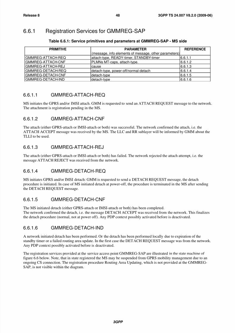
8/3/2019 3GPP TS 24007-V8.2.0
http://slidepdf.com/reader/full/3gpp-ts-24007-v820 48/149
3GPP
3GPP TS 24.007 V8.2.0 (2009-06)48Release 8
6.6.1 Registration Services for GMMREG-SAP
Table 6.6.1: Service primitives and parameters at GMMREG-SAP - MS side
PRIMITIVE PARAMETER(message, info elements of message, other parameters)
REFERENCE
GMMREG-ATTACH-REQ attach-type, READY-timer, STANDBY-timer 6.6.1.1GMMREG-ATTACH-CNF PLMNs MT-caps, attach-type. 6.6.1.2
GMMREG-ATTACH-REJ cause 6.6.1.3
GMMREG-DETACH-REQ detach-type, power-off/normal-detach 6.6.1.4
GMMREG-DETACH-CNF detach-type 6.6.1.5
GMMREG-DETACH-IND detach-type 6.6.1.6
6.6.1.1 GMMREG-ATTACH-REQ
MS initiates the GPRS and/or IMSI attach. GMM is requested to send an ATTACH REQUEST message to the network.The attachment is registration pending in the MS.
6.6.1.2 GMMREG-ATTACH-CNF
The attach (either GPRS-attach or IMSI-attach or both) was successful. The network confirmed the attach, i.e. the
ATTACH ACCEPT message was received by the MS. The LLC and RR sublayer will be informed by GMM about the
TLLI to be used.
6.6.1.3 GMMREG-ATTACH-REJ
The attach (either GPRS-attach or IMSI-attach or both) has failed. The network rejected the attach attempt, i.e. the
message ATTACH REJECT was received from the network.
6.6.1.4 GMMREG-DETACH-REQ
MS initiates GPRS and/or IMSI detach: GMM is requested to send a DETACH REQUEST message, the detach
procedure is initiated. In case of MS initiated detach at power-off, the procedure is terminated in the MS after sending
the DETACH REQUEST message.
6.6.1.5 GMMREG-DETACH-CNF
The MS initiated detach (either GPRS-attach or IMSI-attach or both) has been completed.
The network confirmed the detach, i.e. the message DETACH ACCEPT was received from the network. This finalizesthe detach procedure (normal, not at power off). Any PDP context possibly activated before is deactivated.
6.6.1.6 GMMREG-DETACH-IND
A network initiated detach has been performed. Or the detach has been performed locally due to expiration of the
standby timer or a failed routing area update. In the first case the DETACH REQUEST message was from the network.
Any PDP context possibly activated before is deactivated.
The registration services provided at the service access point GMMREG-SAP are illustrated in the state machine of
figure 6.6 below. Note, that in state registered the MS may be suspended from GPRS mobility management due to an
ongoing CS connection. The registration procedure Routing Area Updating, which is not provided at the GMMREG-
SAP, is not visible within the diagram.
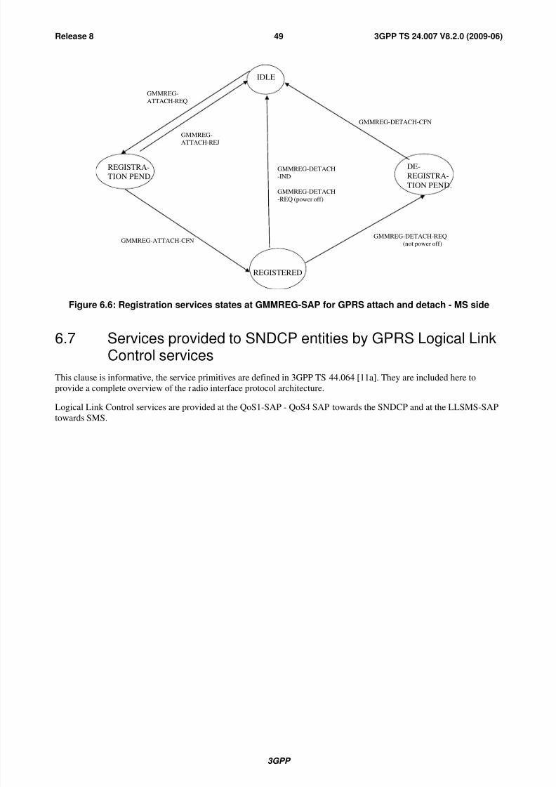
8/3/2019 3GPP TS 24007-V8.2.0
http://slidepdf.com/reader/full/3gpp-ts-24007-v820 49/149
3GPP
3GPP TS 24.007 V8.2.0 (2009-06)49Release 8
IDLE
REGISTRA-
TION PEND.
GMMREG-
ATTACH-REQ
GMMREG-ATTACH-CFN
GMMREG-ATTACH-REJ
GMMREG-DETACH-CFN
REGISTERED
GMMREG-DETACH
-IND
GMMREG-DETACH
-REQ (power off)
GMMREG-DETACH-REQ
(not power off)
DE-
REGISTRA-
TION PEND.
Figure 6.6: Registration services states at GMMREG-SAP for GPRS attach and detach - MS side
6.7 Services provided to SNDCP entities by GPRS Logical LinkControl services
This clause is informative, the service primitives are defined in 3GPP TS 44.064 [11a]. They are included here to
provide a complete overview of the radio interface protocol architecture.
Logical Link Control services are provided at the QoS1-SAP - QoS4 SAP towards the SNDCP and at the LLSMS-SAP
towards SMS.

8/3/2019 3GPP TS 24007-V8.2.0
http://slidepdf.com/reader/full/3gpp-ts-24007-v820 50/149
3GPP
3GPP TS 24.007 V8.2.0 (2009-06)50Release 8
6.7.1 Service state diagram for QoS1-SAP, QoS2-SAP, QoS3-SAP andQoS4-SAP
LL-ESTABLISH-REQ
LL-ESTABLISH-IND
LL-ESTABLISH-CNF
LL-ESTABLISH-RSP
LL-UNITDATA-REQ/IND
LL-UNITDATA-REQ/IND LL-RELEASE-IND
LL-UNITDATA-REQ/IND
LL-DATA-REQ/CNF/IND
IDLE
WAIT
EST
LL-RELEASE-CNF
LL-RELEASE-REQ
LL-RELEASE-IND
LL-RELEASE-REQ
LL-RELEASE-REQ
LL-RELEASE-IND
WAIT
DISC.
ABM
EST
Figure 6.7: States to establish and release ABM mode operation
6.7.2 Service primitives for QoS1-SAP, QoS2-SAP, QoS3-SAP andQoS4-SAP
Table 6.7.2: Service primitives and parameters at QoS1 to QoS4 - MS side
PRIMITIVE PARAMETER(message, info elements of message, other parameters)
REFERENCE
LL-ESTABLISH-REQ TLLI, SNDCP requested parameters (XID) 6.7.2.1
LL-ESTABLISH-CNF TLLI, SNDCP negotiated parameters (XID) 6.7.2.2
LL-ESTABLISH-IND TLLI, SNDCP requested parameters (XID), N201 6.7.2.3
LL-ESTABLISH-RSP TLLI, SNDCP negotiated parameters (XID) 6.7.2.4
LL-RELEASE-REQ TLLI 6.7.2.5
LL-RELEASE-CFN TLLI 6.7.2.6
LL-RELEASE-IND TLLI 6.7.2.7
LL-XID-REQ TLLI, SNDCP requested parameters (XID) 6.7.2.8LL-XID-IND TLLI, SNDCP requested parameters (XID), N201 6.7.2.9
LL-XID-RSP TLLI, SNDCP negotiated parameters (XID) 6.7.2.10
LL-XID-CNF TLLI, SNDCP negotiated parameters (XID), N201 6.7.2.11
LL-DATA-REQ TLLI, N-PDU, local reference 6.7.2.12
LL-DATA-CNF TLLI, local reference 6.7.2.13
LL-DATA-IND TLLI, N-PDU 6.7.2.14
LL-UNITDATA-REQ TLLI, N-PDU, protect, cipher 6.7.2.15
LL-UNITDATA-IND TLLI, N-PDU 6.7.2.16
LL-STATUS-IND TLLI, cause 6.7.2.17
6.7.2.1 LL-ESTABLISH-REQ
A LLC SABM frame will be sent to establish the LLC ABM mode.

8/3/2019 3GPP TS 24007-V8.2.0
http://slidepdf.com/reader/full/3gpp-ts-24007-v820 51/149
3GPP
3GPP TS 24.007 V8.2.0 (2009-06)51Release 8
6.7.2.2 LL-ESTABLISH-CNF
A LLC UA frame is received, the LLC ABM mode has been established.
6.7.2.3 LL-ESTABLISH-IND
A LLC SABM frame is received.
6.7.2.4 LL-ESTABLISH-RSP
A LLC UA frame will be sent, the ABM mode is established.
6.7.2.5 LL-RELEASE-REQ
A LLC DISC frame will be sent to change to LLC ADM mode.
6.7.2.6 LL-RELEASE-CNF
The LLC link has been disconnected, LLC is in ADM mode.
6.7.2.7 LL-RELEASE-IND
LLC is in idle mode.
6.7.2.8 LL-XID-REQ
An LLC XID frame will be sent.
6.7.2.9 LL-XID-IND
An LLC XID frame has been received.
6.7.2.10 LL-XID-RSP
An LLC XID frame will be sent as a response to a received XID frame.
6.7.2.11 LL-XID-CNF
An LLC XID frame has been received as a response to a sent XID frame.
6.7.2.12 LL-DATA-REQ
An LLC I frame will be sent to the peer entity.
6.7.2.13 LL-DATA-CNF
Successful reception of an LLC I frame has been acknowledged by the peer entity.
6.7.2.14 LL-DATA-IND
An LLC I frame has been received from the peer entity.
6.7.2.15 LL-UNITDATA-REQ
An LLC UI frame will be sent to the peer entity.

8/3/2019 3GPP TS 24007-V8.2.0
http://slidepdf.com/reader/full/3gpp-ts-24007-v820 52/149
3GPP
3GPP TS 24.007 V8.2.0 (2009-06)52Release 8
6.7.2.16 LL-UNITDATA-IND
An LLC UI frame has been received from the peer entity.
6.7.2.17 LL-STATUS-IND
Indication used by LLC to transfer LLC failures to the SNDCP sublayer. The failure may also be caused due to errors atthe RLC/MAC layer.
6.8 Location services at the type A LMU side
The location services (e.g. transfer of timing related measurement information by a type A LMU) are provided at theservice access point MNLCS-SAP. The service provided by the CM sublayer to support the location services is defined
in 3GPP TS 44.071 [8a].
6.8.1 Service state diagram
The positioning services provided at the service access point MNLCS-SAP are illustrated in the state diagram of
figure 6.8.
Connected
Idle
MNLCS-BEGIN-REQ
IND
MNLCS-END-REQ
IND
MNLCS-END-REQ
IND
MNLCS-FACILITY-REQ
IND
STATES:IDLE - No LCS signalling transaction pending.
CONN - LCS signalling transaction established.
Figure 6.8: Service graph of the Location Services Support entity - type A LMU side

8/3/2019 3GPP TS 24007-V8.2.0
http://slidepdf.com/reader/full/3gpp-ts-24007-v820 53/149
3GPP
3GPP TS 24.007 V8.2.0 (2009-06)53Release 8
6.8.2 Service primitives
Table 6.8: Primitives and Parameters at MNLCS-SAP - type A LMU side
PRIMITIVES PARAMETERS(Info elements of message)
REFERENCE
MNLCS_BEGIN_REQ REGISTER 6.8.2.1MNLCS_BEGIN_IND REGISTER 6.8.2.2MNLCS_FACILITY_REQ FACILITY 6.8.2.3
MNLCS_FACILITY_IND FACILITY 6.8.2.4MNLCS_END_REQ RELEASE COMPLETE 6.8.2.5
MNLCS_END_IND RELEASE COMPLETE 6.8.2.6
6.8.2.1 MNLCS_BEGIN_REQ
Request to send a REGISTER message in order to establish a signalling transaction for the provision of location
services. The request for transfer of a location service facility may be included.
6.8.2.2 MNLCS_BEGIN_IND
Receipt of a REGISTER message, a signalling transaction is established for the provision of location services after
receipt of a REGISTER message. The indication of a location service facility may be included.
6.8.2.3 MNLCS_FACILITY_REQ
Request to send a FACILITY message for the provision of a location service invocation. The request for transfer of a
location service facility may be included.
6.8.2.4 MNLCS_FACILITY_IND
Receipt of a FACILITY message, a location service facility has been requested.
6.8.2.5 MNLCS_END_REQ
Request to send a RELEASE COMPLETE message in order to release the signalling transaction. The request fortransfer of a location service facility may be included.
6.8.2.6 MNLCS_END_IND
Receipt of a RELEASE COMPLETE message, the signalling transaction has been released. The indication of a location
service facility may be included.
7 Services provided by signalling layer 3 on theNetwork side
In this clause, the services provided by signalling layer 3 on the network side are described which belong to the CM
sub-layer functional blocks of CC, SMS, LCS, and SS. The services corresponding to further functional blocks of the
CM sublayer are not further described in this clause.
7.1 Call control services
The Call Control services are provided by multiple CC entities at the service access point MNCC-SAP.
The Call Control service class consists of the following services:
- call establishment;

8/3/2019 3GPP TS 24007-V8.2.0
http://slidepdf.com/reader/full/3gpp-ts-24007-v820 54/149
3GPP
3GPP TS 24.007 V8.2.0 (2009-06)54Release 8
- call maintaining;
- call termination;
- call related Supplementary Services Support.
7.1.1 Service state diagramThe Call Control services provided at the service access point MNCC-SAP are illustrated in figure 7.1.
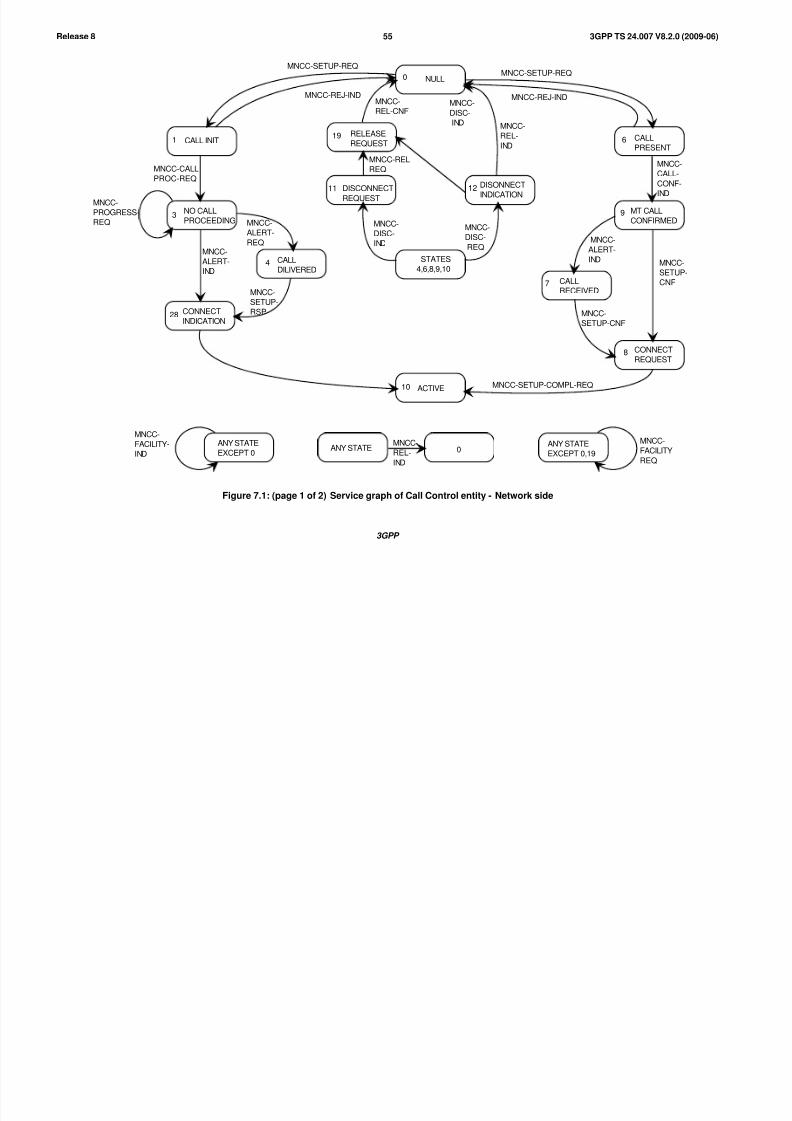
8/3/2019 3GPP TS 24007-V8.2.0
http://slidepdf.com/reader/full/3gpp-ts-24007-v820 55/149
3GPP
3GPP TS 24.007 V8.2.0 (2009-06)55Release 8
RELEASE
REQUEST
DISONNECT
INDICATION
DISCONNECT
REQUEST
CALL INIT
NO CALL
PROCEEDING
CALL
DILIVERED
ACTIVE
CALL
RECEIVED
CONNECT
REQUEST
MT CALL
CONFIRMED
CALL
PRESENT
NULL0
1
3
4
10
19
12
6
9
7
8
11
MNCC-
REL-
IND
MNCC-REJ-IND
MNCC-SETUP-REQ
MNCC-
DISC-
IND
MNCC-
DISC-
REQMNCC-
ALERT-
IND
MNCC-
FACILITY-
IND
ANY STATE
EXCEPT 0ANY STATE
MNCC-
REL-
IND
0ANY STATE
EXCEPT 0,19
MNCC-
FACILITY
REQ
MNCC-SETUP-REQ
MNCC-REJ-IND
STATES
4,6,8,9,10
MNCC-
REL-CNFMNCC-
DISC-
IND
MNCC-
CALL-
CONF-
IND
MNCC-
ALERT-
IND MNCC-
SETUP-
CNF
MNCC-
SETUP-CNF
MNCC-SETUP-COMPL-REQ
MNCC-CALL
PROC-REQ
CONNECT
INDICATION28
MNCC-
PROGRESS-
REQ MNCC-
ALERT-
REQ
MNCC-
SETUP-
RSP
MNCC-REL
REQ
Figure 7.1: (page 1 of 2) Service graph of Call Control entity - Network side
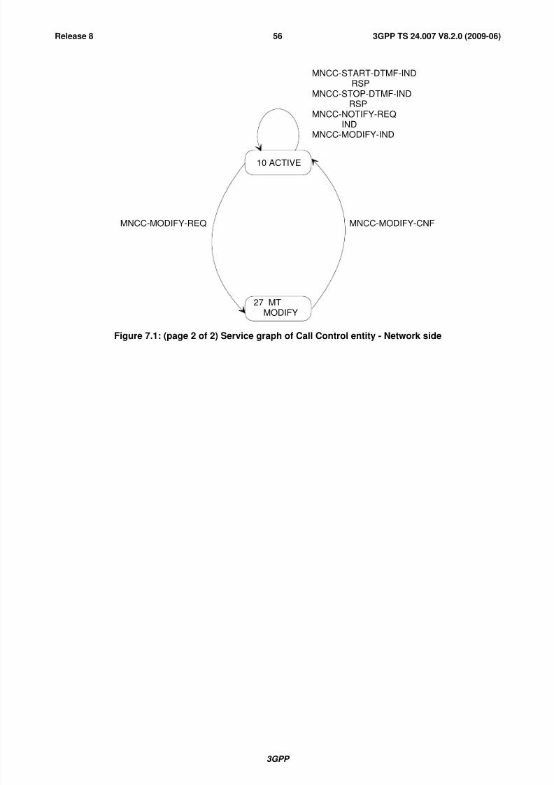
8/3/2019 3GPP TS 24007-V8.2.0
http://slidepdf.com/reader/full/3gpp-ts-24007-v820 56/149
3GPP
3GPP TS 24.007 V8.2.0 (2009-06)56Release 8
10 ACTIVE
27 MTMODIFY
MNCC-MODIFY-CNFMNCC-MODIFY-REQ
MNCC-START-DTMF-INDRSP
MNCC-STOP-DTMF-INDRSP
MNCC-NOTIFY-REQIND
MNCC-MODIFY-IND
Figure 7.1: (page 2 of 2) Service graph of Call Control entity - Network side
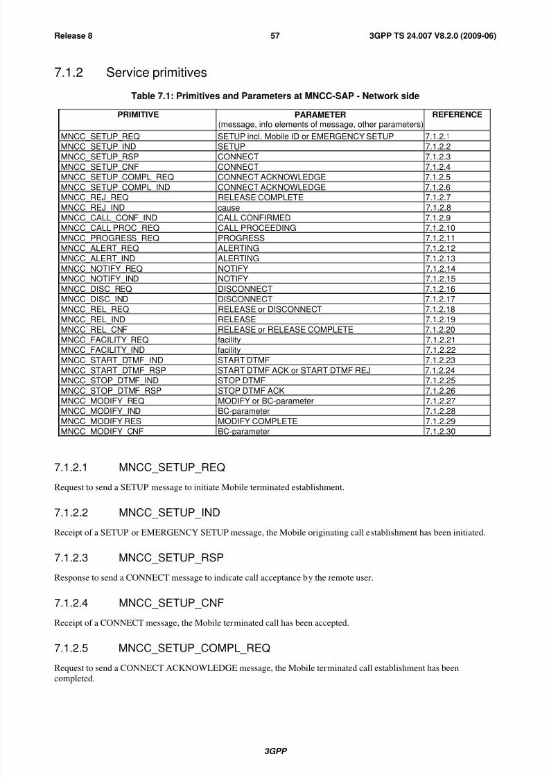
8/3/2019 3GPP TS 24007-V8.2.0
http://slidepdf.com/reader/full/3gpp-ts-24007-v820 57/149
3GPP
3GPP TS 24.007 V8.2.0 (2009-06)57Release 8
7.1.2 Service primitives
Table 7.1: Primitives and Parameters at MNCC-SAP - Network side
PRIMITIVE PARAMETER(message, info elements of message, other parameters)
REFERENCE
MNCC_SETUP_REQ SETUP incl. Mobile ID or EMERGENCY SETUP 7.1.2.1MNCC_SETUP_IND SETUP 7.1.2.2
MNCC_SETUP_RSP CONNECT 7.1.2.3
MNCC_SETUP_CNF CONNECT 7.1.2.4
MNCC_SETUP_COMPL_REQ CONNECT ACKNOWLEDGE 7.1.2.5
MNCC_SETUP_COMPL_IND CONNECT ACKNOWLEDGE 7.1.2.6
MNCC_REJ_REQ RELEASE COMPLETE 7.1.2.7
MNCC_REJ_IND cause 7.1.2.8
MNCC_CALL_CONF_IND CALL CONFIRMED 7.1.2.9
MNCC_CALL PROC_REQ CALL PROCEEDING 7.1.2.10
MNCC_PROGRESS_REQ PROGRESS 7.1.2.11
MNCC_ALERT_REQ ALERTING 7.1.2.12
MNCC_ALERT_IND ALERTING 7.1.2.13
MNCC_NOTIFY_REQ NOTIFY 7.1.2.14MNCC_NOTIFY_IND NOTIFY 7.1.2.15
MNCC_DISC_REQ DISCONNECT 7.1.2.16
MNCC_DISC_IND DISCONNECT 7.1.2.17
MNCC_REL_REQ RELEASE or DISCONNECT 7.1.2.18
MNCC_REL_IND RELEASE 7.1.2.19
MNCC_REL_CNF RELEASE or RELEASE COMPLETE 7.1.2.20
MNCC_FACILITY_REQ facility 7.1.2.21
MNCC_FACILITY_IND facility 7.1.2.22
MNCC_START_DTMF_IND START DTMF 7.1.2.23
MNCC_START_DTMF_RSP START DTMF ACK or START DTMF REJ 7.1.2.24
MNCC_STOP_DTMF_IND STOP DTMF 7.1.2.25
MNCC_STOP_DTMF_RSP STOP DTMF ACK 7.1.2.26
MNCC_MODIFY_REQ MODIFY or BC-parameter 7.1.2.27
MNCC_MODIFY_IND BC-parameter 7.1.2.28MNCC_MODIFY RES MODIFY COMPLETE 7.1.2.29
MNCC_MODIFY_CNF BC-parameter 7.1.2.30
7.1.2.1 MNCC_SETUP_REQ
Request to send a SETUP message to initiate Mobile terminated establishment.
7.1.2.2 MNCC_SETUP_IND
Receipt of a SETUP or EMERGENCY SETUP message, the Mobile originating call establishment has been initiated.
7.1.2.3 MNCC_SETUP_RSP
Response to send a CONNECT message to indicate call acceptance by the remote user.
7.1.2.4 MNCC_SETUP_CNF
Receipt of a CONNECT message, the Mobile terminated call has been accepted.
7.1.2.5 MNCC_SETUP_COMPL_REQ
Request to send a CONNECT ACKNOWLEDGE message, the Mobile terminated call establishment has been
completed.
8/3/2019 3GPP TS 24007-V8.2.0
http://slidepdf.com/reader/full/3gpp-ts-24007-v820 58/149
3GPP
3GPP TS 24.007 V8.2.0 (2009-06)58Release 8
7.1.2.6 MNCC_SETUP_COMPL_IND
Indication of the receipt of a CONNECT ACKNOWLEDGE message, the Mobile originating call establishment has
been completed.
7.1.2.7 MNCC_REJ_REQ
Reject the Mobile originated call establishment if the call cannot be accepted.
7.1.2.8 MNCC_REJ_IND
A Mobile terminated call was rejected by the MS, e.g. because of missing compatibility.
7.1.2.9 MNCC_CALL_CONF_IND
Receipt of a CALL CONFIRMED message, the Mobile terminated call has been confirmed. A bearer capability
different from that given in MNCC_SETUP_REQ may be offered to the remote calling user.
7.1.2.10 MNCC_CALL_PROC_REQ
Request to send a CALL PROCEEDING message to indicate to the Mobile originating user that call establishment has
been initiated in the Network and no more call establishment information will be accepted.
7.1.2.11 MNCC_PROGRESS_REQ
Request to send a PROGRESS message or to piggy-back a progress IE in a suitable CC message in order to give the
Mobile user information about the call, e.g. that the call is progressing in the PLMN/ISDN environment, or that the call
has left the PLMN/ISDN environment, or that in-band tones/announcement are available.
7.1.2.12 MNCC_ALERT_REQ
Request to send an ALERTING message to indicate to the Mobile originating user that remote called user alerting has
been initiated.
7.1.2.13 MNCC_ALERT_IND
Receipt of an ALERTING message from the Mobile terminated user to be sent to the remote calling user to indicate that
user alerting has been initiated.
7.1.2.14 MNCC_NOTIFY_REQ
Request to send information pertaining to a call, such as user suspended, to the Mobile originating or the Mobile
terminated user.
7.1.2.15 MNCC_NOTIFY_IND
Indication from the Mobile originating or Mobile terminated user of information pertaining to a call, such as remote
user suspended.
7.1.2.16 MNCC_DISC_REQ
Request to send a DISCONNECT message to the MS in order to clear the end-to-end connection.
7.1.2.17 MNCC_DISC_IND
Receipt of a DISCONNECT message, the MS indicates that the end-to-end connection is cleared.
8/3/2019 3GPP TS 24007-V8.2.0
http://slidepdf.com/reader/full/3gpp-ts-24007-v820 59/149
3GPP
3GPP TS 24.007 V8.2.0 (2009-06)59Release 8
7.1.2.18 MNCC_REL_REQ
Request to send a RELEASE message to inform the MS that the network intends to release the MM connection and the
correspondent call reference.
7.1.2.19 MNCC_REL_IND
Receipt of a RELEASE message, the MS intends to release its MM connection and call reference. The Network is
requested to release its call reference and MM connection.
7.1.2.20 MNCC_REL_CNF
The RELEASE COMPLETE message has been received, the MM connection in the MS has been released, the Network
itself shall release its MM connection and the corresponding call reference.
7.1.2.21 MNCC_FACILITY_REQ
Request to transport a facility IE for call related supplementary service invocations.
7.1.2.22 MNCC_FACILITY_IND
Indication that a facility IE for call related supplementary service invocations has been received.
7.1.2.23 MNCC_START_DTMF_IND
Indicate the receipt of a START DTMF message in order to start a DTMF control operation.
7.1.2.24 MNCC_START_DTMF_RSP
Request to send a START DTMF ACKNOWLEDGE or START DTMF REJECT message in order to acknowledge or
reject the start of a DTMF control operation.
7.1.2.25 MNCC_STOP_DTMF_IND
Indicate the receipt of a STOP DTMF message in order to stop a DTMF control operation.
7.1.2.26 MNCC_STOP_DTMF_RSP
Request to send a STOP DTMF ACKNOWLEDGE message in order to acknowledge the completion of a DTMFcontrol operation.
7.1.2.27 MNCC_MODIFY_REQ
Request to start the Mobile terminating in-call modification.
7.1.2.28 MNCC_MODIFY_IND
Receipt of a MODIFY message, the Mobile originating in-call modification has been initiated.
7.1.2.29 MNCC_MODIFY_RES
Response to send a MODIFY COMPLETE to indicate to the Mobile user that the mobile originating in-call
modification procedure has been completed.
7.1.2.30 MNCC_MODIFY_CNFConfirmation that the Mobile terminating in-call modification has been completed.
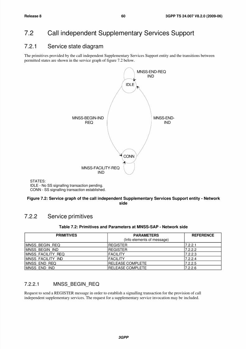
8/3/2019 3GPP TS 24007-V8.2.0
http://slidepdf.com/reader/full/3gpp-ts-24007-v820 60/149
3GPP
3GPP TS 24.007 V8.2.0 (2009-06)60Release 8
7.2 Call independent Supplementary Services Support
7.2.1 Service state diagram
The primitives provided by the call independent Supplementary Services Support entity and the transitions between
permitted states are shown in the service graph of figure 7.2 below.
IDLE
CONN
MNSS-END-
IND
MNSS-BEGIN-IND
REQ
MNSS-FACILITY-REQIND
MNSS-END-REQIND
STATES:IDLE - No SS signalling transaction pending.CONN - SS signalling transaction established.
Figure 7.2: Service graph of the call independent Supplementary Services Support entity - Networkside
7.2.2 Service primitives
Table 7.2: Primitives and Parameters at MNSS-SAP - Network side
PRIMITIVES PARAMETERS(Info elements of message)
REFERENCE
MNSS_BEGIN_REQ REGISTER 7.2.2.1MNSS_BEGIN_IND REGISTER 7.2.2.2
MNSS_FACILITY_REQ FACILITY 7.2.2.3
MNSS_FACILITY_IND FACILITY 7.2.2.4
MNSS_END_REQ RELEASE COMPLETE 7.2.2.5
MNSS_END_IND RELEASE COMPLETE 7.2.2.6
7.2.2.1 MNSS_BEGIN_REQ
Request to send a REGISTER message in order to establish a signalling transaction for the provision of call
independent supplementary services. The request for a supplementary service invocation may be included.
8/3/2019 3GPP TS 24007-V8.2.0
http://slidepdf.com/reader/full/3gpp-ts-24007-v820 61/149
3GPP
3GPP TS 24.007 V8.2.0 (2009-06)61Release 8
7.2.2.2 MNSS_BEGIN_IND
Receipt of a REGISTER message, a signalling transaction is established for the provision of call independent
supplementary services. The indication of a supplementary service invocation may be included.
7.2.2.3 MNSS_FACILITY_REQ
Request to send a FACILITY message for the provision of a call independent supplementary service facility.
7.2.2.4 MNSS_FACILITY_IND
Receipt of a FACILITY message, a supplementary service facility has been requested.
7.2.2.5 MNSS_END_REQ
Request to send a RELEASE COMPLETE message in order to release the signalling transaction by sending a
RELEASE COMPLETE message. The request for transfer of a supplementary service facility may be included.
7.2.2.6 MNSS_END_IND
Indication that the signalling transaction has been released after receipt of a RELEASE COMPLETE message. The
indication of a supplementary service facility may be included.
7.3 Short Message Services Support
The service provided by the CM sublayer to support the short message service are defined in 3GPP TS 24.011 [8].
7.4 Services provided to SNDCP and SMS entities by GPRS
Logical Link Control servicesThis clause is informative, the service primitives are defined in 3GPP TS 44.064 [11a]. They are included here to
provide a complete overview of the radio interface protocol architecture.
On the network side, Logical Link Control services are provided at the QoS1-SAP - QoS4 SAP towards the SNDCP
and at the LLSMS-SAP towards SMS.
7.4.1 Service state diagram for QoS1-SAP, QoS2-SAP, QoS3-SAP andQoS4-SAP
The service state diagram is identical on the network side is identical to the one shown in figure 6.7 for the mobile side.

8/3/2019 3GPP TS 24007-V8.2.0
http://slidepdf.com/reader/full/3gpp-ts-24007-v820 62/149
3GPP
3GPP TS 24.007 V8.2.0 (2009-06)62Release 8
7.4.2 Service primitives for QoS1-SAP, QoS2-SAP, QoS3-SAP and QoS4-SAP
PRIMITIVE PARAMETER(message, info elements of message, other parameters)
REFERENCE
LL-ESTABLISH-REQ TLLI, SNDCP requested parameters (XID) 7.4.2.1
LL-ESTABLISH-CNF TLLI, SNDCP negotiated parameters (XID), N201 7.4.2.2
LL-ESTABLISH-IND TLLI, SNDCP requested parameters (XID), N201 7.4.2.3
LL-ESTABLISH-RSP TLLI, SNDCP negotiated parameters (XID) 7.4.2.4
LL-RELEASE-REQ TLLI 7.4.2.5
LL-RELEASE-CNF TLLI 7.4.2.6
LL-RELEASE-IND TLLI 7.4.2.7
LL-XID-REQ TLLI, SNDCP requested parameters (XID) 7.4.2.8
LL-XID-IND TLLI, SNDCP requested parameters (XID), N201 7.4.2.9
LL-XID-RSP TLLI, SNDCP negotiated parameters (XID) 7.4.2.10
LL-XID-CNF TLLI, SNDCP negotiated parameters (XID), N201 7.4.2.11
LL-DATA-REQ TLLI, N-PDU, local reference 7.4.2.12
LL-DATASENT-IND TLLI, local reference, V(S) 7.4.2.13LL-DATA-CNF TLLI, local reference 7.4.2.14
LL-DATA-IND TLLI, N-PDU 7.4.2.15
LL-UNITDATA-REQ TLLI, N-PDU, protect, cipher 7.4.2.16
LL-UNITDATA-IND TLLI, N-PDU 7.4.2.17
LL-STATUS-IND TLLI, cause 7.4.2.18
7.4.2.1 LL-ESTABLISH-REQ
A LLC SABM frame will be sent to establish the LLC ABM mode.
7.4.2.2 LL-ESTABLISH-CNFA LLC UA frame is received, the LLC ABM mode has been established.
7.4.2.3 LL-ESTABLISH-IND
A LLC SABM frame is received.
7.4.2.4 LL-ESTABLISH-RSP
A LLC UA frame will be sent, the ABM mode is established.
7.4.2.5 LL-RELEASE-REQA LLC DISC frame will be sent to change to LLC ADM mode.
7.4.2.6 LL-RELEASE-CNF
The LLC link has been disconnected, LLC is in ADM mode.
7.4.2.7 LL-RELEASE-IND
LLC is in idle mode.
7.4.2.8 LL-XID-REQ
An LLC XID frame will be sent.
8/3/2019 3GPP TS 24007-V8.2.0
http://slidepdf.com/reader/full/3gpp-ts-24007-v820 63/149
3GPP
3GPP TS 24.007 V8.2.0 (2009-06)63Release 8
7.4.2.9 LL-XID-IND
An LLC XID frame is received.
7.4.2.10 LL-XID-RSP
An LLC XID frame will be sent as a reply to a received XID frame.
7.4.2.11 LL-XID-CNF
An LLC XID frame has been received as a reply to a sent XID frame.
7.4.2.12 LL-DATA-REQ
An LLC I frame will be sent to the peer entity.
7.4.2.13 LL-DATASENT-IND
The sent LLC frame was sent with the V(S) indicated.
7.4.2.14 LL-DATA-CNF
Successful reception of an LLC I frame has been acknowledged by the peer entity.
7.4.2.15 LL-DATA-IND
An LLC I frame has been received form the peer entity.
7.4.2.16 LL-UNITDATA-REQ
An LLC UI frame will be sent to the peer entity.
7.4.2.17 LL-UNITDATA-IND
An LLC UI frame has been received from the peer entity.
7.4.2.18 LL-STATUS-IND
Indication used by LLC to transfer LLC failures to the SNDCP sublayer. The failure may also be caused due to errors at
the RLC/MAC layer.
7.5 Session Management Services for GPRS and MBMSOn the network side Session Management Services are provided at the SNSM-SAP and SMREG-SAP. At the SMREG-
SAP, the assumption taken is that the MS initiated primary and secondary PDP context activation, the MS initiated PDP
context modification and deactivation, and the MBMS context activation and deactivation are not visible, i.e. the
service for these functions on the network side stops in the SM sublayer entity.

8/3/2019 3GPP TS 24007-V8.2.0
http://slidepdf.com/reader/full/3gpp-ts-24007-v820 64/149
3GPP
3GPP TS 24.007 V8.2.0 (2009-06)64Release 8
7.5.1 Session Management Services for SMREG-SAP
Table 7.5.1: Primitives and Parameters at SMREG-SAP - network side
PRIMITIVE PARAMETER(message, info elements of message, other parameters)
REFERENCE
SMREG-PDP-ACTIVATE-REQ PDP address, APN, protocol configuration options 7.5.1.1SMREG-PDP-ACTIVATE-REJ Cause, PDP address, APN, protocol configuration
options7.5.1.2
SMREG-PDP-DEACTIVATE-REQ NSAPI(s), teardown indicator, cause, protocolconfiguration options, MBMS protocol configurationoptions
7.5.1.3
SMREG-PDP-DEACTIVATE-CNF NSAPI(s) , protocol configuration options, MBMSprotocol configuration options
7.5.1.4
SMREG-PDP-MODIFY-REQ QoS, NSAPI, protocol configuration options 7.5.1.5
SMREG PDP-MODIFY-CNF NSAPI, protocol configuration options 7.5.1.6
SMREG PDP-MODIFY-REJ NSAPI, protocol configuration options 7.5.1.7
SMREG-MBMS-ACTIVATE-REQ Multicast address, APN, MBMS protocol configurationoptions
7.5.1.8
SMREG-MBMS-ACTIVATE-REJ Cause, multicast address, APN, MBMS protocol
configuration options
7.5.1.9
7.5.1.1 SMREG-PDP-ACTIVATE-REQ
The network initiates a PDP context activation. SM is requested to send the REQUEST PDP CONTEXTACTIVATION message to the MS. The PDP context is pending activation. The network expects that the MS continues
with a normal MS initiated PDP context activation. Therefore, at the SMREG-SAP no confirmation is provided.
7.5.1.2 SMREG-PDP-ACTIVATE-REJ
The network initiated PDP context activation failed. Either the REQUEST PDP CONTEXT ACTIVATION REJECT
message was received from the MS, or lower layer failure or timer expiry caused abortion of the PDP context activationprocedure.
7.5.1.3 SMREG-PDP-DEACTIVATE-REQ
The network initiates a PDP or MBMS context deactivation. SM is requested to send a DEACTIVATE PDP
CONTEXT REQUEST message. The PDP context is pending deactivation. Presence of the teardown indicator will lead
to deactivation of all PDP contexts coupled to the identified PDP address. NSAPI(s) to be deallocated from the SNDCP
entity via the SNSM-SAP for the GSM case, are included in the primitive.
7.5.1.4 SMREG-PDP-DEACTIVATE-CNF
The network initiated PDP or MBMS context deactivation has been concluded. The MS confirmed the PDP context
deactivation, i.e. the DEACTIVATE PDP CONTEXT ACCEPT message was received. Then SM ordered SNDCP to
locally release LLC link(s) not further needed for the GSM case. In the UMTS case, release of affected GTP-U
tunnel(s) towards the RNC has taken place. The PDP context is deactivated.
7.5.1.5 SMREG-PDP-MODIFY-REQ
The network initiates a modification of the PDP context. SM is requested to send a MODIFY PDP CONTEXT
REQUEST message to the MS. The PDP context is pending modification.
7.5.1.6 SMREG-PDP-MODIFY-CNF
The PDP context modification has been concluded. The MS confirmed the PDP context modification, i.e. the MODIFY
PDP CONTEXT ACCEPT message was received. Then, for the GSM case, SM ordered SNDCP to adjust the affectedLLC link as required. For the UMTS case, RAB properties were updated as required. The PDP context is modified.
8/3/2019 3GPP TS 24007-V8.2.0
http://slidepdf.com/reader/full/3gpp-ts-24007-v820 65/149
3GPP
3GPP TS 24.007 V8.2.0 (2009-06)65Release 8
7.5.1.7 SMREG-PDP-MODIFY-REJ
The PDP context modification has been rejected. Due to timer expiry or lower layer failure the modification procedure
has been aborted.
7.5.1.8 SMREG-MBMS-ACTIVATE-REQ
The network initiates an MBMS context activation. SM is requested to send the REQUEST MBMS CONTEXT
ACTIVATION message to the MS. The MBMS context is pending activation. The network expects that the MS
continues with the MBMS context activation. Therefore, at the SMREG-SAP no confirmation is provided.
7.5.1.9 SMREG-MBMS-ACTIVATE-REJ
The network initiated MBMS context activation failed. Either the REQUEST MBMS CONTEXT REJECT message
was received from the MS, or lower layer failure or timer expiry caused abortion of the MBMS context activation
procedure.
7.5.2 Session Management Services for SNSM-SAP
The SNSM-SAP service primitives are defined in 3GPP TS 44.065 [12a].
7.6 Location services at the Network side
The location services (e.g. network initiation of timing related measurements in a type A LMU) are provided at the
service access point MNLCS-SAP. The service provided by the CM sublayer to support the location services is definedin 3GPP TS 44.071 [8a] (for communication with a type A LMU only).
7.6.1 Service state diagram
The primitives provided by the call independent Location Services Support entity and the transitions between permitted
states are shown in the service graph of figure 7.6 below.

8/3/2019 3GPP TS 24007-V8.2.0
http://slidepdf.com/reader/full/3gpp-ts-24007-v820 66/149
3GPP
3GPP TS 24.007 V8.2.0 (2009-06)66Release 8
Connected
Idle
MNLCS-BEGIN-REQ
IND
MNLCS-END-REQ
IND
MNLCS-END-REQ
IND
MNLCS-FACILITY-REQ
IND
STATES:IDLE - No LCS signalling transaction pending.CONN - LCS signalling transaction established.
Figure 7.6: Service graph of the Location Services Support entity - Network side
7.6.2 Service primitives
Table 7.6: Primitives and Parameters at MNLCS-SAP - Network side
PRIMITIVES PARAMETERS(Info elements of message)
REFERENCE
MNLCS_BEGIN_REQ REGISTER 7.6.2.1MNLCS_BEGIN_IND REGISTER 7.6.2.2MNLCS_FACILITY_REQ FACILITY 7.6.2.3
MNLCS_FACILITY_IND FACILITY 7.6.2.4MNLCS_END_REQ RELEASE COMPLETE 7.6.2.5MNLCS_END_IND RELEASE COMPLETE 7.6.2.6
7.6.2.1 MNLCS_BEGIN_REQ
Request to send a REGISTER message in order to establish a signalling transaction for the provision of location
services. The request for a location service invocation may be included.

8/3/2019 3GPP TS 24007-V8.2.0
http://slidepdf.com/reader/full/3gpp-ts-24007-v820 67/149
3GPP
3GPP TS 24.007 V8.2.0 (2009-06)67Release 8
7.6.2.2 MNLCS_BEGIN_IND
Receipt of a REGISTER message, a signalling transaction is established for the provision of location services. The
indication of a location service invocation may be included.
7.6.2.3 MNLCS_FACILITY_REQ
Request to send a FACILITY message for the provision of a location service facility.
7.6.2.4 MNLCS_FACILITY_IND
Receipt of a FACILITY message, a location service facility has been requested.
7.6.2.5 MNLCS_END_REQ
Request to send a RELEASE COMPLETE message in order to release the signalling transaction by sending a
RELEASE COMPLETE message. The request for transfer of a location service facility may be included.
7.6.2.6 MNLCS_END_IND
Indication that the signalling transaction has been released after receipt of a RELEASE COMPLETE message. The
indication of a location service facility may be included.
8 Services assumed from signalling layers 1 and 2
The services provided by layer 2 are defined in detail in 3GPP TS 44.005 [4]. A short summary is given below.
In addition, layer 1 communicates directly with layer 3 for information transfer related to channel management and to
measurement control. See subclause 8.5 below.
8.1 Priority
Messages from layer 3 can be sent with:
- no priority;
i.e. the messages are sent in first-in-first-out order;
- priority;
i.e. a message with this indication is sent as early as possible by layer 2.
8.2 Unacknowledged information transfer
Transfer of unacknowledged information using the primitives DL_UNIT_DATA_ REQUEST/INDICATION.
8.3 Acknowledged information transfer
Transfer of information in multiframe acknowledged mode including:
- establishment of data link connection between L3 entities;
- transfer of information in acknowledged mode;
- release of the data link connection.
8/3/2019 3GPP TS 24007-V8.2.0
http://slidepdf.com/reader/full/3gpp-ts-24007-v820 68/149
3GPP
3GPP TS 24.007 V8.2.0 (2009-06)68Release 8
The primitives associated with acknowledged information transfer are:
- DL_ESTABLISH_REQUEST/INDICATION/CONFIRM for establishment of acknowledged mode;
- DL_DATA_REQUEST/INDICATION for requesting the transmission of a message unit and for indicating the
reception of a message unit;
- DL_SUSPEND_REQUEST/DL_RELEASE_CONFIRM for requesting and confirming the suspension of theacknowledged information transfer in the MS upon channel change;
- DL_RESUME_REQUEST/DL_ESTABLISH_CONFIRM for requesting and confirming the resumption of the
acknowledged information transfer in the MS after suspension at channel change;
- DL_RELEASE_REQUEST/INDICATION/CONFIRM for the termination of acknowledged mode operation;
- DL_RECONNECT_REQUEST for requesting the re-establishment of acknowledged information transfer in the
MS on the old channel after channel change failure.
8.4 Random access
The transmission/reception of a random access burst is controlled by the primitives
DL_RANDOM_ACCESS_REQUEST/INDICATION/CONFIRM.
8.5 Channel management and measurements
The management of channels, i.e. their activation, deactivation, configuration, deconfiguration, through-connection and
disconnection is controlled by the RR sublayer in layer 3. The measurements performed by the physical layer are also
controlled by the RR sublayer of layer 3 and they are reported to layer 3.
These functions use the primitives MPH_INFORMATION_REQUEST/INDICATION/CONFIRMATION.
9 Interlayer service interfaces on the MS side
In addition to the services described in this clause, the RR entity and MM entity also provide services to CM entities
which do not belong to the functional blocks of CC, SMS, and SS. (For example, the RR entity provides service to
Group Call and Broadcast Call entities.) These services are not further described in this clause.
9.1 Services provided by the Radio Resource Managemententity
The Radio Resource Management (RR) sublayer provides a service to the Mobility Management entity (MM).
The RR services are used for:
- establishing control channel connections;
- releasing control channel connections;
- control-data transfer.
The Radio Resource Management services are represented by the RR-service primitives.

8/3/2019 3GPP TS 24007-V8.2.0
http://slidepdf.com/reader/full/3gpp-ts-24007-v820 69/149
3GPP
3GPP TS 24.007 V8.2.0 (2009-06)69Release 8
MS side Network side
MobilityManagementsublayer
Radio ResourceManagementsublayer
RR-primitives
RR sublayer peer-to-peer protocol
RRSAP
Figure 9.1: Services provided at RR-SAP - MS side
9.1.1 Service state diagram
The primitives provided by the Radio Resource Management entity and the transition between permitted states are
shown in figure 9.2.
ALLSTATES
IDLE
CONPEND
DEDI-CATED
RR-EST-REQ RR-UNIT-DATA-IND
RR-ABORT-IND
RR-EST-IND
RR-REL-INDRR-ABORT-
REQ
RR-EST-CNFRR-SYNC-IND(ciph)(res ass)(channel mode modify)
RR-DATA-REQ-INDRR-UNIT-DATA-IND
Figure 9.2: Service graph of the Radio Resource Management - MS side
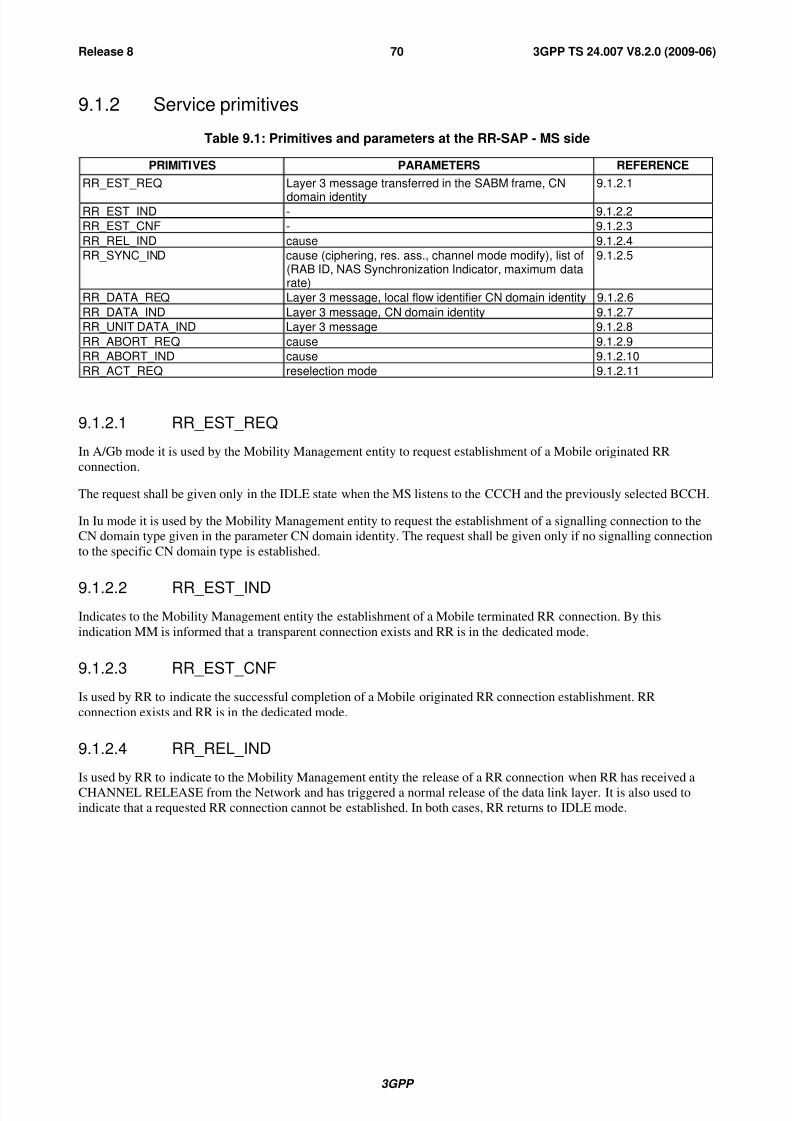
8/3/2019 3GPP TS 24007-V8.2.0
http://slidepdf.com/reader/full/3gpp-ts-24007-v820 70/149
3GPP
3GPP TS 24.007 V8.2.0 (2009-06)70Release 8
9.1.2 Service primitives
Table 9.1: Primitives and parameters at the RR-SAP - MS side
PRIMITIVES PARAMETERS REFERENCE
RR_EST_REQ Layer 3 message transferred in the SABM frame, CN
domain identity
9.1.2.1
RR_EST_IND - 9.1.2.2
RR_EST_CNF - 9.1.2.3
RR_REL_IND cause 9.1.2.4
RR_SYNC_IND cause (ciphering, res. ass., channel mode modify), list of(RAB ID, NAS Synchronization Indicator, maximum datarate)
9.1.2.5
RR_DATA_REQ Layer 3 message, local flow identifier CN domain identity 9.1.2.6
RR_DATA_IND Layer 3 message, CN domain identity 9.1.2.7
RR_UNIT DATA_IND Layer 3 message 9.1.2.8
RR_ABORT_REQ cause 9.1.2.9
RR_ABORT_IND cause 9.1.2.10
RR_ACT_REQ reselection mode 9.1.2.11
9.1.2.1 RR_EST_REQ
In A/Gb mode it is used by the Mobility Management entity to request establishment of a Mobile originated RR
connection.
The request shall be given only in the IDLE state when the MS listens to the CCCH and the previously selected BCCH.
In Iu mode it is used by the Mobility Management entity to request the establishment of a signalling connection to theCN domain type given in the parameter CN domain identity. The request shall be given only if no signalling connection
to the specific CN domain type is established.
9.1.2.2 RR_EST_IND
Indicates to the Mobility Management entity the establishment of a Mobile terminated RR connection. By this
indication MM is informed that a transparent connection exists and RR is in the dedicated mode.
9.1.2.3 RR_EST_CNF
Is used by RR to indicate the successful completion of a Mobile originated RR connection establishment. RR
connection exists and RR is in the dedicated mode.
9.1.2.4 RR_REL_IND
Is used by RR to indicate to the Mobility Management entity the release of a RR connection when RR has received a
CHANNEL RELEASE from the Network and has triggered a normal release of the data link layer. It is also used to
indicate that a requested RR connection cannot be established. In both cases, RR returns to IDLE mode.
8/3/2019 3GPP TS 24007-V8.2.0
http://slidepdf.com/reader/full/3gpp-ts-24007-v820 71/149
3GPP
3GPP TS 24.007 V8.2.0 (2009-06)71Release 8
9.1.2.5 RR_SYNC_IND
Is used for synchronizing RR and the Mobility Management entity after the establishment of a Mobile originated or
Mobile terminated RR connection. This indication is provided to MM in the following cases:
- ciphering has been started (ciphering);
- integrity protection has been started (integrity) (UMTS only);
- a traffic channel has been assigned (res. ass. = "resource assigned");
- the channel mode has been modified (channel mode modify).
In Iu mode, in case of a resource assignment or channel mode modification, RR indicates to the Mobility Management
entity the list of RAB IDs and, optionally,
– the NAS Synchronization Indicators associated with the assigned or modified radio bearers; or
– the maximum data rate (at RLC layer) associated with the assigned or modified radio bearers, if no NAS
Synchronization Indicator is available.
9.1.2.5a Void
9.1.2.5b Void
9.1.2.6 RR_DATA_REQ
Is used by the Mobility Management entity to send control data to its peer entity on the Network side via an existing RR
connection.
9.1.2.7 RR_DATA_IND
Is used by RR to indicate control-data, which has been received from its peer entity on the Network side via an existingRR connection.
For UMTS, RR_DATA_IND is also used to indicate whether control-data has been:
- successfully integrity checked;
- unsuccessfully integrity checked;
- received with no integrity protection.
9.1.2.7a Void
9.1.2.8 RR_UNIT_DATA_IND
Is used by RR to provide MM with system info. The system info is received on the current BCCH if RR is in the IDLE
state. If a RR connection has been established, the system info is received on the SACCH.
9.1.2.9 RR_ABORT_REQ
Request to abort an existing RR connection or a RR connection in progress. The data link, if already established, shall
be released by a normal release procedure (DISC/UA) initiated by the MS. This is the only way the MS can trigger the
release of a RR connection in case of exceptional conditions. The RR returns to the IDLE state.
9.1.2.10 RR_ABORT_IND
Indication that the RR connection has been aborted by a lower layer failure and RR has returned to the IDLE state.
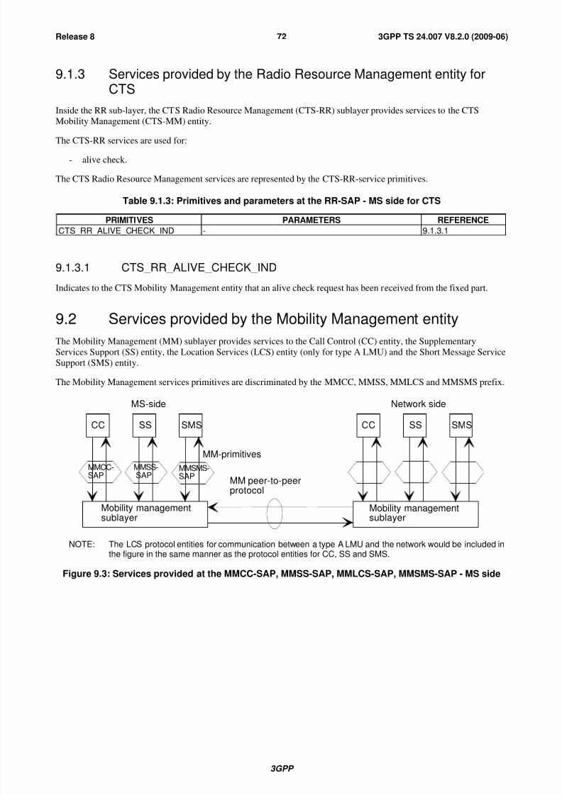
8/3/2019 3GPP TS 24007-V8.2.0
http://slidepdf.com/reader/full/3gpp-ts-24007-v820 72/149
3GPP
3GPP TS 24.007 V8.2.0 (2009-06)72Release 8
9.1.3 Services provided by the Radio Resource Management entity forCTS
Inside the RR sub-layer, the CTS Radio Resource Management (CTS-RR) sublayer provides services to the CTS
Mobility Management (CTS-MM) entity.
The CTS-RR services are used for:
- alive check.
The CTS Radio Resource Management services are represented by the CTS-RR-service primitives.
Table 9.1.3: Primitives and parameters at the RR-SAP - MS side for CTS
PRIMITIVES PARAMETERS REFERENCE
CTS_RR_ALIVE_CHECK_IND - 9.1.3.1
9.1.3.1 CTS_RR_ALIVE_CHECK_IND
Indicates to the CTS Mobility Management entity that an alive check request has been received from the fixed part.
9.2 Services provided by the Mobility Management entity
The Mobility Management (MM) sublayer provides services to the Call Control (CC) entity, the Supplementary
Services Support (SS) entity, the Location Services (LCS) entity (only for type A LMU) and the Short Message Service
Support (SMS) entity.
The Mobility Management services primitives are discriminated by the MMCC, MMSS, MMLCS and MMSMS prefix.
CC SS SMS CC SS SMS
MMCC-SAP
MMSS-SAP
MMSMS-SAP
Mobility managementsublayer
Mobility managementsublayer
MM-primitives
MM peer-to-peerprotocol
MS-side Network side
NOTE: The LCS protocol entities for communication between a type A LMU and the network would be included in
the figure in the same manner as the protocol entities for CC, SS and SMS.
Figure 9.3: Services provided at the MMCC-SAP, MMSS-SAP, MMLCS-SAP, MMSMS-SAP - MS side

8/3/2019 3GPP TS 24007-V8.2.0
http://slidepdf.com/reader/full/3gpp-ts-24007-v820 73/149
3GPP
3GPP TS 24.007 V8.2.0 (2009-06)73Release 8
9.2.1 Service state diagram
The primitives provided by the Mobility Management entity towards Call Control, call independent Supplementary
Service Support, Location Services Support for type A LMU and towards Short Messages Service Support and the
transition between permitted states are illustrated in figure 9.4.
IDLE
DEDI-CATED
MMXX-UNIT-DATA-IND
MMXX-REL-REQ-IND
MMXX-REEST-CNF
MMXX-REL-REQ/IND
MMXX-EST-REQ
MMXX-EST-CNF
MMCC-SYNC-IND
(channel mode modify)
(res ass)MMXX-DATA-REQ IND
MMXX-UNIT-DATA-REQ IND
MMXX-PROMPT-IND
MMXX-PROMPT-
REJ
MMXX-REL-REQ
MMSS-EST-IND
MMXX-REEST-
REQMMXX-ERR-IND
MMXX-UNIT-
DATA-REQ
CONNPEND
CONNSUSP
RE-EST-PEND
NOTE 1: MMCC-primitives only at MMCC-SAP.NOTE 2: The prefix MMXX is used for substitution of MMCC, MMSS, MMLCS or MMSMS.
Figure 9.4: Service graph of the Mobility Management entity - MS side

8/3/2019 3GPP TS 24007-V8.2.0
http://slidepdf.com/reader/full/3gpp-ts-24007-v820 74/149
3GPP
3GPP TS 24.007 V8.2.0 (2009-06)74Release 8
9.2.2 Service primitives
Table 9.2: Primitives and Parameters at MMCC-SAP, MMSS-SAP (for type A LMU), MMLCS-SAP orMMSMS-SAP - MS side
PRIMITIVES PARAMETERS REFERENCE
MMXX_EST_REQ (see note 1) Parameters for the appropriateCM SERVICE REQUEST (if any)
9.2.2.1
MMXX_EST_IND (see note 1) First CM message 9.2.2.2
MMXX_EST_CNF (see note 1) - 9.2.2.3
MMXX_REL_REQ (see note 1) cause 9.2.2.4
MMXX_REL_IND (see note 1) cause 9.2.2.5
MMXX_DATA_REQ (see note 1) Layer 3 message 9.2.2.6
MMXX_DATA_IND (see note 1) Layer 3 message 9.2.2.7
MMXX_UNIT_DATA_REQ (see note 1) Layer 3 message 9.2.2.8
MMXX_UNIT_DATA_IND (see note 1) Layer 3 message 9.2.2.9
MMCC_SYNC_IND (see note 2) cause: res.ass; list of (RAB ID, NASSynchronization Indicator, maximum datarate)
9.2.2.10
MMXX_REEST_REQ (see note 1) 9.2.2.11
MMXX_REEST_CNF (see note 1) 9.2.2.12
MMXX_ERR_IND (see note 1) cause 9.2.2.13
MMXX_PROMPT_IND (see note 1) - 9.2.2.14
MMXX_PROMPT_REJ (see note 1) - 9.2.2.15
NOTE 1: MMXX is used as substitution for MMCC, MMSS, MMLCS or MMSMS.NOTE 2: Only at MMCC-SAP.
9.2.2.1 MMXX_EST_REQ
Request used by CC, SS, LCS (for type A LMU) and SMS respectively, to request establishment of a MM connection.
Several MM connections may be provided in parallel to the requesting entities. The primitive may contain parameters
which are relevant for the CM SERVICE REQUEST message, e.g. to distinguish a basic call from an emergency call.
9.2.2.2 MMXX_EST_IND
Indication to CC, SS, LCS (for type A LMU) or SMS that a Mobile terminated MM connection has been establishedand the first message has been received from the respective peer entity. Several MM connections may be provided in
parallel. If a MM connection already exists, a new MM connection using the same RR connection is indicated by this
primitive if MM detects a message with a new combination of Protocol Discriminator (PD) and Transaction
Identifier (TI).
9.2.2.3 MMXX_EST_CNF
Successful confirmation of the MM connection establishment by the MM sublayer to be given to the appropriate entity
which has requested the service.
9.2.2.4 MMXX_REL_REQ
Used by CC, SS, LCS (for type A LMU) or SMS respectively, to request release of the MM connection. The
corresponding PD/TI will be released and may be used for a new MM connection.
9.2.2.5 MMXX_REL_IND
Indication of the release of an existing MM connection or a MM connection in progress. This primitive is used in
exceptional cases to indicate that the MM connection cannot be established or kept any longer and PD/TI have been
released.
9.2.2.6 MMXX_DATA_REQ
Request used by the CC, SS or SMS entities for acknowledged control-data transmission.

8/3/2019 3GPP TS 24007-V8.2.0
http://slidepdf.com/reader/full/3gpp-ts-24007-v820 75/149
3GPP
3GPP TS 24.007 V8.2.0 (2009-06)75Release 8
9.2.2.7 MMXX_DATA_IND
Indication used by MM to transfer the received acknowledged control-data to the CC, SS, LCS (for type A LMU) or
SMS entities.
9.2.2.8 MMXX_UNIT_DATA_REQ
Request used by the CC, SS, LCS (for type A LMU) or SMS entities for unacknowledged control-data transmission.
9.2.2.9 MMXX_UNIT_DATA_IND
Indication used by MM to transfer the received unacknowledged control-data to the CC, SS, LCS or SMS entities.
9.2.2.10 MMCC_SYNC_IND
Indication that a dedicated channel assignment has been performed and/or the channel mode has been changed (only
towards the CC entity).
In Iu mode, MM indicates the list of the RAB IDs and, optionally,
– the NAS Synchronization Indicators associated with the assigned or modified radio bearers; or
– the maximum data rate (at RLC layer) associated with the assigned or modified radio bearers, if no NAS
Synchronization Indicator is available.
During a network-initiated in-call modification the CC entity uses the NAS Synchronization Indicator or the maximum
data rate to determine whether a suitable channel for the new call mode is available.
9.2.2.11 MMXX_REEST_REQ
Request to establish a MM connection which has been interrupted by a lower layer failure. The interruption must have
been indicated by MMXX_ERR_IND.
9.2.2.12 MMXX_REEST_CNF
Confirmation of the successful re-establishment of the MM connection. The MM connection will continue with PD/TI
as it had before.
9.2.2.13 MMXX_ERR_IND
Indication of a lower layer failure interrupting the MM connection. The PD/TI are still kept by MM. In case of parallel
transactions this indication is passed to all CM entities for which a MM connection has been established. It is left to the
decision of the appropriate CM entity to either request the re-establishment of the MM connection byMMXX_REEST_REQ or to release it by MMXX_REL_REQ.
9.2.2.14 MMXX_PROMPT_IND
Indication given by MM to inform of the completion of the MM connection to the CC, SS, LCS (for type A LMU) or
SMS entities for a mobile station which supports "Network Initiated MO CM Connection Request".
9.2.2.15 MMXX_PROMPT_REJ
Response to the MMXX_PROMPT_IND indication to the MM entity in a mobile station which supports "Network
Initiated MO CM Connection Request" in case when it is impossible to establish the prompted CM connection e.g. due
to lack of free transaction identifiers.

8/3/2019 3GPP TS 24007-V8.2.0
http://slidepdf.com/reader/full/3gpp-ts-24007-v820 76/149
3GPP
3GPP TS 24.007 V8.2.0 (2009-06)76Release 8
9.3 Services provided by radio resource management entity forGPRS services
The service primitives for UMTS are defined in the present document. The services provided by the Access Stratum
(AS) are specified in 3GPP TS 23.110 [20].
9.3.1 Service primitives for GRR-SAP (GSM only)
The GRR-SAP service primitives are defined in 3GPP TS 44.064 [11a]
[[Table 9.3.1, and chapters 9.3.1.1 - 9.3.1.5 are Void]
9.3.2 Service primitives for GMMRR-SAP (GSM only)
Table 9.3.2: Primitives and Parameters at GMMRR-SAP - MS side
PRIMITIVE PARAMETER(message, info elements of message, other parameters)
REFERENCE
GMMRR-ASSIGN-REQ newTLLI 9.3.2.1
GMMRR-PAGE-IND TLLI 9.3.2.2
9.3.2.1 GMMRR-ASSIGN-REQ
A new TLLI is assigned to the RR sublayer.
9.3.2.2 GMMRR-PAGE-IND
A RR-paging message has been received by the RR sublayer.
9.3.3 Service primitives for RABMAS-SAP (UMTS only)
Table 9.3.3: Primitives and parameters at RABMAS-SAP
PRIMITIVE PARAMETER(message, info elements ofmessage, other parameters)
REFERENCE
RABMAS-RAB-ESTABLISH-IND RAB ID list 9.3.3.1
RABMAS-RAB-ESTABLISH-RES - 9.3.3.2
RABMAS-RAB-ESTABLISH-REJ 9.3.3.3
RABMAS-RAB-RELEASE-IND RAB ID list 9.3.3.4
RABMAS-RAB-RELEASE-RES - 9.3.3.5
RABMAS-STATUS-IND Cause 9.3.3.6
9.3.3.1 RABMAS-RAB-ESTABLISH-IND
Indication from the Access Stratum layer that radio access bearer setup for the indicated list of RAB IDs (contains
NSAPI) has commenced.
9.3.3.2 RABMAS-RAB-ESTABLISH-RES
Response (to RABMAS-RAB-ESTABLISH-IND) used by the RABM entity to inform the Access Stratum sublayer that
the indicated NSAPI (in RAB ID) is currently or has been activated by the SM.

8/3/2019 3GPP TS 24007-V8.2.0
http://slidepdf.com/reader/full/3gpp-ts-24007-v820 77/149
3GPP
3GPP TS 24.007 V8.2.0 (2009-06)77Release 8
9.3.3.3 RABMAS-RAB-ESTABLISH-REJ
Response (to RABMAS-RAB-ESTABLISH-IND) used by the RABM entity to inform the Access Stratum sublayer that
all of the NSAPIs, indicated by RAB ID list in the received RABMAS-RAB-ESTABLISH-IND, have not been
activated by the SM-layer and the attempt to setup the radio access bearers shall be rejected.
9.3.3.4 RABMAS-RAB-RELEASE-IND
Indication from the Access Stratum layer that a radio access bearer for the indicated NSAPI has been released.
9.3.3.5 RABMAS-RAB-RELEASE-RES
Response used by the RABM entity to inform the Access Stratum sublayer that the indicated RAB ID has been released
in the RABM.
9.3.3.6 RABMAS-STATUS-IND
Indication used by the AS sublayer to transfer failures to the RABM.
9.3.4 Service primitives for GMMAS-SAP (UMTS only)
Table 9.3.4: Service primitives and parameters at GMMAS-SAP - MS side
PRIMITIVE PARAMETER(message, info elements of message,
other parameters)
REFERENCE
GMMAS-SECURITY-IND 9.3.4.1
GMMAS-SECURITY-RES CK, IK 9.3.4.2
GMMAS- ESTABLISH-REQ Layer 3-PDU, Establishment cause,Priority, CN Domain Identity, MS Identity,LAI/RAI
9.3.4.3
GMMAS- ESTABLISH-CNF 9.3.4.4GMMAS- ESTABLISH-REJ 9.3.4.5
GMMAS- RELEASE-REQ CN Domain identity 9.3.4.6
GMMAS- RELEASE-IND Cause 9.3.4.7
GMMAS- DATA-REQ Layer 3-PDU, Priority, CN Domain identity 9.3.4.8
GMMAS- DATA-IND Layer 3-PDU 9.3.4.9
GMMAS-PAGE-IND MS Identity type, Paging Cause 9.3.4.10
GMMAS-STATUS-IND Cause 9.3.4.11
9.3.4.1 GMMAS-SECURITY-IND
Indication from the AS sublayer that ciphering (and integrity protection) shall be started. The GMM sublayer uses this
primitive as an indication of the completion of the service request procedure.
9.3.4.2 GMMAS-SECURITY-RES
Ciphering and integrity keys are assigned to the AS sublayer to enable ciphering (and integrity protection).
9.3.4.3 GMMAS-ESTABLISH-REQ
To establish a signalling connection and to carry the initial Layer 3-PDU over the radio interface.
9.3.4.4 GMMAS-ESTABLISH-CNF
Confirmation from the AS sublayer that a PS signalling connection has been established.

8/3/2019 3GPP TS 24007-V8.2.0
http://slidepdf.com/reader/full/3gpp-ts-24007-v820 78/149
3GPP
3GPP TS 24.007 V8.2.0 (2009-06)78Release 8
9.3.4.5 GMMAS-ESTABLISH-REJ
The attempt to establish a PS signalling connection was rejected by the network.
9.3.4.6 GMMAS- RELEASE-REQ
Request used by the MM-sublayer to request the release of the PS signalling connection.
9.3.4.7 GMMAS- RELEASE-IND
Indication from the AS sublayer that the PS signalling connection has been released.
9.3.4.8 GMMAS- DATA-REQ
Request used by the MM-sublayer for transfer of data.
9.3.4.9 GMMAS- DATA-IND
Indication used by the AS sublayer to transfer received data to MM sublayer.
9.3.4.10 GMMAS-PAGE-IND
A paging message has been received by the AS sublayer.
9.3.4.11 GMMAS-STATUS-IND
Indication used by the AS sublayer to transfer failures to the MM sublayer.
9.4 Services provided by the LLC entity for GPRS services
(GSM only)This subclause is informative, the service primitives are defined in 3GPP TS 44.064 [11a]. They are included here to
provide a complete overview of the radio interface protocol architecture.
9.4.1 Service primitives for LLGMM-SAP
Table 9.4.1: Primitives and parameters at LLGMM-SAP - MS side
PRIMITIVE PARAMETER(message, info elements of message, other parameters)
REFERENCE
LLGMM-ASSIGN-REQ oldTLLI, newTLLI, Kc, RAND, Ciphering Algorithm 9.4.1.1
LLGMM-TRIGGER-REQ Cause 9.4.1.2LLGMM-SUSPEND-REQ TLLI 9.4.1.4
LLGMM-RESUME-REQ TLLI 9.4.1.5
LL-UNITDATA-REQ TLLI, GMM-PDU, protect, cipher 9.4.1.8
LL-UNITDATA-IND TLLI, GMM-PDU, cipher 9.4.1.9
LLGMM-STATUS-IND TLLI, cause 9.4.1.10
9.4.1.1 LLGMM-ASSIGN-REQ
A new TLLI and/or a ciphering key and/or a ciphering algorithm is assigned to the LLC sublayer.
9.4.1.2 LLGMM-TRIGGER-REQ
Request to send an LLC PDU to the network. Cause indicates if the primitive is sent to trigger an implicit page
response.

8/3/2019 3GPP TS 24007-V8.2.0
http://slidepdf.com/reader/full/3gpp-ts-24007-v820 79/149
3GPP
3GPP TS 24.007 V8.2.0 (2009-06)79Release 8
9.4.1.3 Void
9.4.1.4 LLGMM-SUSPEND-REQ
All LLC links in ABM mode will cease sending PDUs. GMM messages can still be sent and received.
9.4.1.5 Void
9.4.1.6 Void
9.4.1.7 LLGMM-WINDOW-CNF
The actual LLC's V(R)s for each LLC link in ABM mode are transferred to GMM.
9.4.1.8 LL-UNITDATA-REQ
Request to send a GMM message in unacknowledged mode to the peer entity.
9.4.1.9 LL-UNITDATA-IND
A GMM message in unacknowledged mode has been received from the peer entity.
9.4.1.10 LLGMM-STATUS-IND
Indication used by LLC to transfer LLC failures to the GMM sublayer. The failure may also be caused due to errors at
the RLC/MAC layer.
9.4.2 Service primitives for LLSMS-SAP
Table 9.4.2: Service primitives and parameters at LLSMS-SAP - MS side
PRIMITIVE PARAMETER(message, info elements of message, other parameters)
REFERENCE
LL-UNITDATA-REQ TLLI, SMS-CP-PDU, protect, cipher 9.4.2.1
LL-UNITDATA-IND TLLI, SMS-CP-PDU, 9.4.2.2
9.4.2.1 LL-UNITDATA-REQ
An LLC UI frame will be sent to the peer entity.
9.4.2.2 LL-UNITDATA-INDAn LLC UI frame has been received from the peer entity.
9.5 Services provided by the GMM for GPRS services
The GPRS Mobility Management (GMM) sublayer provides services to the Session Management (SM) entity,
Supplementary Service (SS) entity and the Short Message Service Support (GSMS) entity for message transfer.
9.5.1 Service primitives for GMMSM-SAP
Session Management services may request GPRS service registration or perform procedures needed to activate a
multicast service before activating a PDP or an MBMS context.
8/3/2019 3GPP TS 24007-V8.2.0
http://slidepdf.com/reader/full/3gpp-ts-24007-v820 80/149
3GPP
3GPP TS 24.007 V8.2.0 (2009-06)80Release 8
Table 9.5.1: Primitives and parameters at GMMSM-SAP - MS side
PRIMITIVE PARAMETER(message, info elements of message, other
parameters)
REFERENCE
GMMSM-ESTABLISH-REQ - 9.5.1.1
GMMSM-ESTABLISH-CNF - 9.5.1.2
GMMSM-ESTABLISH-REJ cause 9.5.1.3GMMSM-RELEASE-IND - 9.5.1.4
GMMSM-UNITDATA-REQ SM-PDU 9.5.1.5
GMMSM-UNITDATA-IND SM-PDU 9.5.1.6
9.5.1.1 GMMSM-ESTABLISH-REQ
Request from Session Management to send an ATTACH REQUEST message to the network to setup a GMM
connection. The request is only performed in case the MS is not already attached. The GPRS attach is then indirectly
caused by a request from Session Management, e.g. a requested PDP context activation or MBMS context activation.
9.5.1.2 GMMSM-ESTABLISH-CNF
The network has send the ATTACH ACCEPT message to the MS, the indirect attach was successful. Now, Session
Management can proceed with the Session Management request, e.g. the PDP context activation or the MBMS context
activation..
9.5.1.3 GMMSM-ESTABLISH-REJ
The network has rejected the attach. The MS has received the ATTACH REJECT message.
9.5.1.4 GMMSM-RELEASE-IND
The GPRS Mobility Management informs the Session Management that the MS has been GPRS detached, e.g. by timer
expiry, and therefore, the PDP context(s) and the MBMS context(s), if any, are not valid anymore.
9.5.1.5 GMMSM-UNITDATA-REQ
The GMM is requested to forward a SM PDU to LLC in order to send it in unacknowledged more to the peer entity.
9.5.1.6 GMMSM-UNITDATA-IND
The GMM forwards a SM PDU, which has been received in unacknowledged mode via LLC from the peer entity.
9.5.2 Void
9.5.3 Service primitives for GMMSMS-SAP
The Short Message entity may request from the GMM entity the GMM IMSI registration state before an MO SMS
transmission is initiated.
Table 9.5.3: Primitives and parameters at GMMSMS-SAP - MS side
PRIMITIVE PARAMETER(message, info elements of message, other
parameters)
REFERENCE
GMMSMS-REG-STATE-REQ - 9.5.3.1
GMMSM- REG-STATE -RSP Registration state 9.5.3.2
8/3/2019 3GPP TS 24007-V8.2.0
http://slidepdf.com/reader/full/3gpp-ts-24007-v820 81/149
3GPP
3GPP TS 24.007 V8.2.0 (2009-06)81Release 8
9.5.3.1 GMMSMS-REG-STATE-REQ
Request for the current IMSI registration state from the Short Message entity.
9.5.3.2 GMMSM- REG-STATE -RSP
The current IMSI registration state is sent to the Short Message entity.
9.5.4 Service primitives for PMMSMS-SAP
Table 9.5.4: Primitives and Parameters at PMMSMS-SAP - MS side
PRIMITIVES PARAMETERS(message, info elements of message, other
parameters)
REFERENCE
PMMSMS_EST_REQ Mobile-ID 9.5.4.1
PMMSMS_EST_CNF - 9.5.4.2
PMMSMS_ERROR_IND Cause 9.5.4.3
PMMSMS_UNITDATA_REQ SMS-PDU 9.5.4.4
PMMSMS_UNITDATA_IND SMS-PDU 9.5.4.5
9.5.4.1 PMMSMS_EST _REQ
The GMM is requested to establish a PS signalling conection.
9.5.4.2 PMMSMS_EST _CNF
The GMM indicates a PS signalling connection is established.
9.5.4.3 PMMSMS_ERROR_IND
The GMM indicates that a PS signalling connection has been released.
9.5.4.4 PMMSMS_UNITDATA_REQ
The GMM is requested to forward a SMS PDU in order to send it to the peer entity.
9.5.4.5 PMMSMS_UNITDATA_IND
Indication used by GMM to transfer the received data to the GSMS entities.
9.5.5 Service primitives for GMMRABM-SAP (UMTS only)
Table 9.5.5: Service primitives and parameters at GMMRABM-SAP – MS side
PRIMITIVE PARAMETER(message, info elements ofmessage, other parameters)
REFERENCE
GMMRABM-REESTABLISH-REQ 9.5.5.1
GMMRABM-REESTABLISH-RSP 9.5.5.2
GMMRABM-REESTABLISH-REJ Cause 9.5.5.3
NOTE: Confirmation to the RABMGMM-REESTABLISH-REQ is given to the RABM in the form of indicationsfrom the AS sublayer that establishment of RABs has commenced or been completed.
8/3/2019 3GPP TS 24007-V8.2.0
http://slidepdf.com/reader/full/3gpp-ts-24007-v820 82/149
3GPP
3GPP TS 24.007 V8.2.0 (2009-06)82Release 8
9.5.5.1 GMMRABM-REESTABLISH-REQ
This primitive is used by the RABM entity to inform the GMM sublayer that UL user data has been received for an
NSAPI without an active RAB. GMM shall initiate a service request procedure to re-establish the RAB for the
NSAPI(S).
9.5.5.2 GMMRABM-REESTABLISH-RSP
This primitive is used by the GMM sublayer to inform the RABM entity that the reception of the Service Request
message has been acknowledged by the network.
9.5.5.3 GMMRABM-REESTABLISH-REJ
This primitive is used by the GMM sublayer to inform the RABM entity that the re-establishment of RABs by the
service request procedure has failed.
9.5.6 Service primitives for GMMSS-SAP
Supplementary Services may request GPRS service registration before sending SS PDU.
Table 9.5.6: Primitives and parameters at GMMSS-SAP - MS side
PRIMITIVE PARAMETER(message, info elements of message, other
parameters)
REFERENCE
GMMSS-ESTABLISH-REQ - 9.5.6.1
GMMSS-ESTABLISH-CNF - 9.5.6.2
GMMSS-ESTABLISH-REJ cause 9.5.6.3
GMMSS-RELEASE-IND - 9.5.6.4
GMMSS-UNITDATA-REQ SS-PDU 9.5.6.5
GMMSS-UNITDATA-IND SS-PDU 9.5.6.6
9.5.6.1 GMMSS-ESTABLISH-REQ
Request from Supplementary Services to send an ATTACH REQUEST message to the network to setup a GMM
connection. The request is only performed in case the MS is not already attached. The GPRS attach is then indirectly
caused by a sending of SS PDU.
9.5.6.2 GMMSS-ESTABLISH-CNF
The network has send the ATTACH ACCEPT message to the MS, the indirect attach was successful. Now
Supplementary Services can proceed with sending SS PDU.
9.5.6.3 GMMSS-ESTABLISH-REJ
The network has rejected the attach. The MS has received the ATTACH REJECT message.
9.5.6.4 GMMSS-RELEASE-IND
The GPRS mobility management informs the Supplementary Services that the MS has been GPRS detached, e.g. by
timer expiry.
9.5.6.5 GMMSS-UNITDATA-REQ
The GMM is requested to forward a SS PDU to lower layer in order to send it to the peer entity.
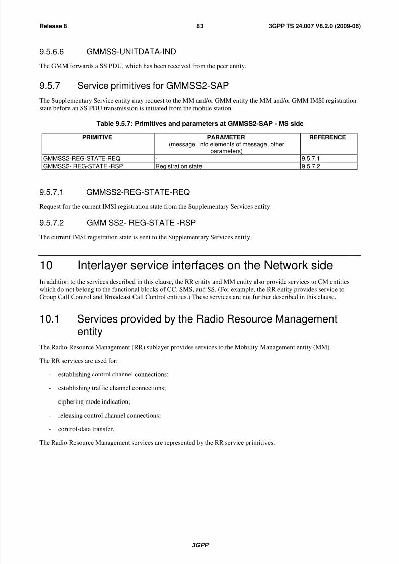
8/3/2019 3GPP TS 24007-V8.2.0
http://slidepdf.com/reader/full/3gpp-ts-24007-v820 83/149
3GPP
3GPP TS 24.007 V8.2.0 (2009-06)83Release 8
9.5.6.6 GMMSS-UNITDATA-IND
The GMM forwards a SS PDU, which has been received from the peer entity.
9.5.7 Service primitives for GMMSS2-SAP
The Supplementary Service entity may request to the MM and/or GMM entity the MM and/or GMM IMSI registrationstate before an SS PDU transmission is initiated from the mobile station.
Table 9.5.7: Primitives and parameters at GMMSS2-SAP - MS side
PRIMITIVE PARAMETER(message, info elements of message, other
parameters)
REFERENCE
GMMSS2-REG-STATE-REQ - 9.5.7.1
GMMSS2- REG-STATE -RSP Registration state 9.5.7.2
9.5.7.1 GMMSS2-REG-STATE-REQ
Request for the current IMSI registration state from the Supplementary Services entity.
9.5.7.2 GMM SS2- REG-STATE -RSP
The current IMSI registration state is sent to the Supplementary Services entity.
10 Interlayer service interfaces on the Network side
In addition to the services described in this clause, the RR entity and MM entity also provide services to CM entities
which do not belong to the functional blocks of CC, SMS, and SS. (For example, the RR entity provides service to
Group Call Control and Broadcast Call Control entities.) These services are not further described in this clause.
10.1 Services provided by the Radio Resource Managemententity
The Radio Resource Management (RR) sublayer provides services to the Mobility Management entity (MM).
The RR services are used for:
- establishing control channel connections;
- establishing traffic channel connections;
- ciphering mode indication;
- releasing control channel connections;
- control-data transfer.
The Radio Resource Management services are represented by the RR service primitives.
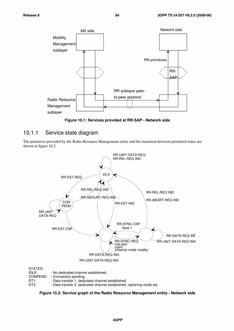
8/3/2019 3GPP TS 24007-V8.2.0
http://slidepdf.com/reader/full/3gpp-ts-24007-v820 84/149
3GPP
3GPP TS 24.007 V8.2.0 (2009-06)84Release 8
MS side Network side
Mobility
Management
sublayer
RR-
SAP
RR-primitives
RR sublayer peer-
to-peer protocolRadio Resource
Management
sublayer
Figure 10.1: Services provided at RR-SAP - Network side
10.1.1 Service state diagram
The primitives provided by the Radio Resource Management entity and the transition between permitted states are
shown in figure 10.2.
RR-UNIT-DATA-REQRR-REL-REQ IND
RR-REL-REQ IND
RR-ABORT-REQ INDRR-EST-IND
RR-SYNC-CNFNote 1
RR-EST-REQ
RR-REL-REQ IND
RR-ABOURT-REQ IND
RR-UNIT-DATA-REQ
RR-EST-CNF
IDLE
CONPEND
RR-SYNC-REQ(res ass)(ciph)(channel mode modify)
RR-DATA-REQ IND
RR-UNIT-DATA-REQ IND
RR-DATA-REQ IN RR-UNIT-DATA-REQ IND
STATES:IDLE: - No dedicated channel established.CONPEND: - Connection pending.DT1: - Data transfer 1, dedicated channel established.DT2: - Data transfer 2, dedicated channel established, ciphering mode set.
Figure 10.2: Service graph of the Radio Resource Management entity - Network side
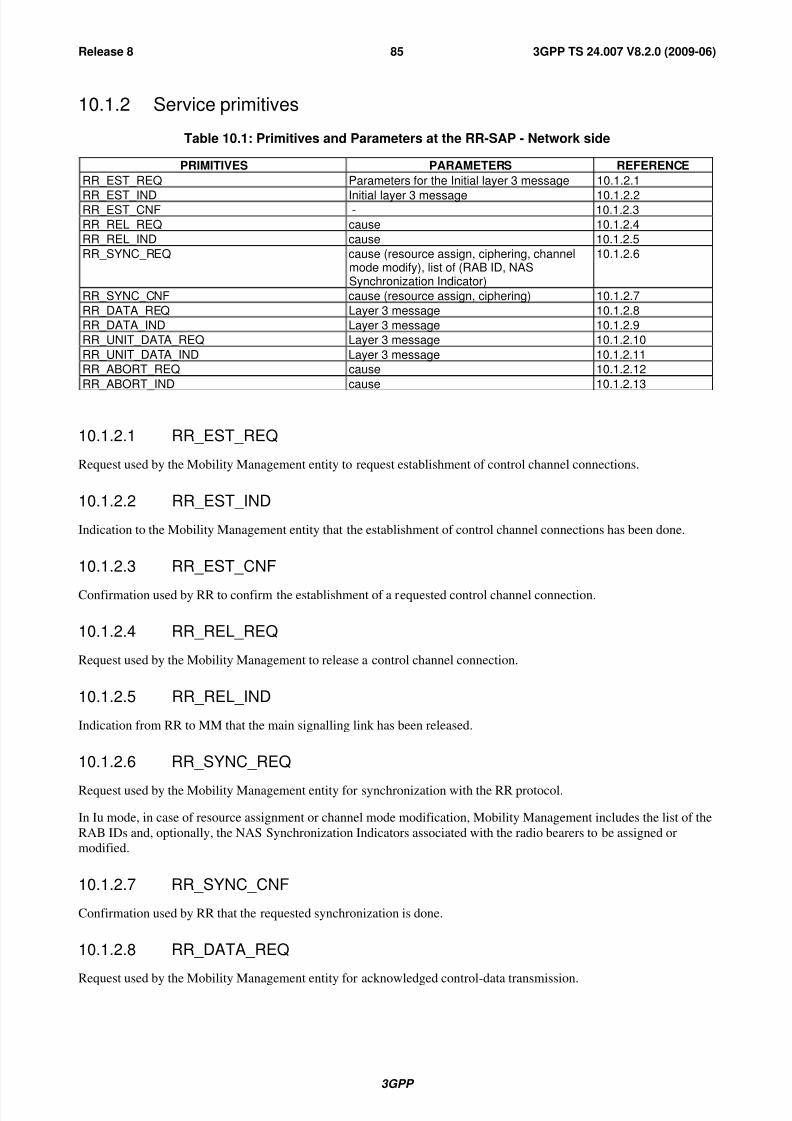
8/3/2019 3GPP TS 24007-V8.2.0
http://slidepdf.com/reader/full/3gpp-ts-24007-v820 85/149
3GPP
3GPP TS 24.007 V8.2.0 (2009-06)85Release 8
10.1.2 Service primitives
Table 10.1: Primitives and Parameters at the RR-SAP - Network side
PRIMITIVES PARAMETERS REFERENCE
RR_EST_REQ Parameters for the Initial layer 3 message 10.1.2.1
RR_EST_IND Initial layer 3 message 10.1.2.2RR_EST_CNF - 10.1.2.3
RR_REL_REQ cause 10.1.2.4
RR_REL_IND cause 10.1.2.5
RR_SYNC_REQ cause (resource assign, ciphering, channelmode modify), list of (RAB ID, NASSynchronization Indicator)
10.1.2.6
RR_SYNC_CNF cause (resource assign, ciphering) 10.1.2.7
RR_DATA_REQ Layer 3 message 10.1.2.8
RR_DATA_IND Layer 3 message 10.1.2.9
RR_UNIT_DATA_REQ Layer 3 message 10.1.2.10
RR_UNIT_DATA_IND Layer 3 message 10.1.2.11
RR_ABORT_REQ cause 10.1.2.12
RR_ABORT_IND cause 10.1.2.13
10.1.2.1 RR_EST_REQ
Request used by the Mobility Management entity to request establishment of control channel connections.
10.1.2.2 RR_EST_IND
Indication to the Mobility Management entity that the establishment of control channel connections has been done.
10.1.2.3 RR_EST_CNF
Confirmation used by RR to confirm the establishment of a requested control channel connection.
10.1.2.4 RR_REL_REQ
Request used by the Mobility Management to release a control channel connection.
10.1.2.5 RR_REL_IND
Indication from RR to MM that the main signalling link has been released.
10.1.2.6 RR_SYNC_REQ
Request used by the Mobility Management entity for synchronization with the RR protocol.
In Iu mode, in case of resource assignment or channel mode modification, Mobility Management includes the list of the
RAB IDs and, optionally, the NAS Synchronization Indicators associated with the radio bearers to be assigned or
modified.
10.1.2.7 RR_SYNC_CNF
Confirmation used by RR that the requested synchronization is done.
10.1.2.8 RR_DATA_REQ
Request used by the Mobility Management entity for acknowledged control-data transmission.
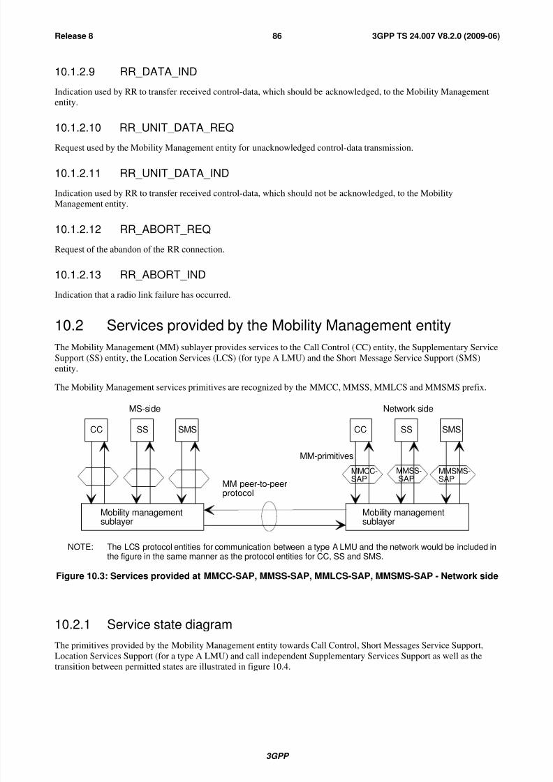
8/3/2019 3GPP TS 24007-V8.2.0
http://slidepdf.com/reader/full/3gpp-ts-24007-v820 86/149
3GPP
3GPP TS 24.007 V8.2.0 (2009-06)86Release 8
10.1.2.9 RR_DATA_IND
Indication used by RR to transfer received control-data, which should be acknowledged, to the Mobility Management
entity.
10.1.2.10 RR_UNIT_DATA_REQ
Request used by the Mobility Management entity for unacknowledged control-data transmission.
10.1.2.11 RR_UNIT_DATA_IND
Indication used by RR to transfer received control-data, which should not be acknowledged, to the Mobility
Management entity.
10.1.2.12 RR_ABORT_REQ
Request of the abandon of the RR connection.
10.1.2.13 RR_ABORT_IND
Indication that a radio link failure has occurred.
10.2 Services provided by the Mobility Management entity
The Mobility Management (MM) sublayer provides services to the Call Control (CC) entity, the Supplementary Service
Support (SS) entity, the Location Services (LCS) (for type A LMU) and the Short Message Service Support (SMS)
entity.
The Mobility Management services primitives are recognized by the MMCC, MMSS, MMLCS and MMSMS prefix.
CC SS SMS CC SS SMS
MMCC-SAP
MMSS-SAP
MMSMS-SAP
Mobility managementsublayer
Mobility managementsublayer
MM-primitives
MM peer-to-peerprotocol
MS-side Network side
NOTE: The LCS protocol entities for communication between a type A LMU and the network would be included inthe figure in the same manner as the protocol entities for CC, SS and SMS.
Figure 10.3: Services provided at MMCC-SAP, MMSS-SAP, MMLCS-SAP, MMSMS-SAP - Network side
10.2.1 Service state diagram
The primitives provided by the Mobility Management entity towards Call Control, Short Messages Service Support,
Location Services Support (for a type A LMU) and call independent Supplementary Services Support as well as the
transition between permitted states are illustrated in figure 10.4.
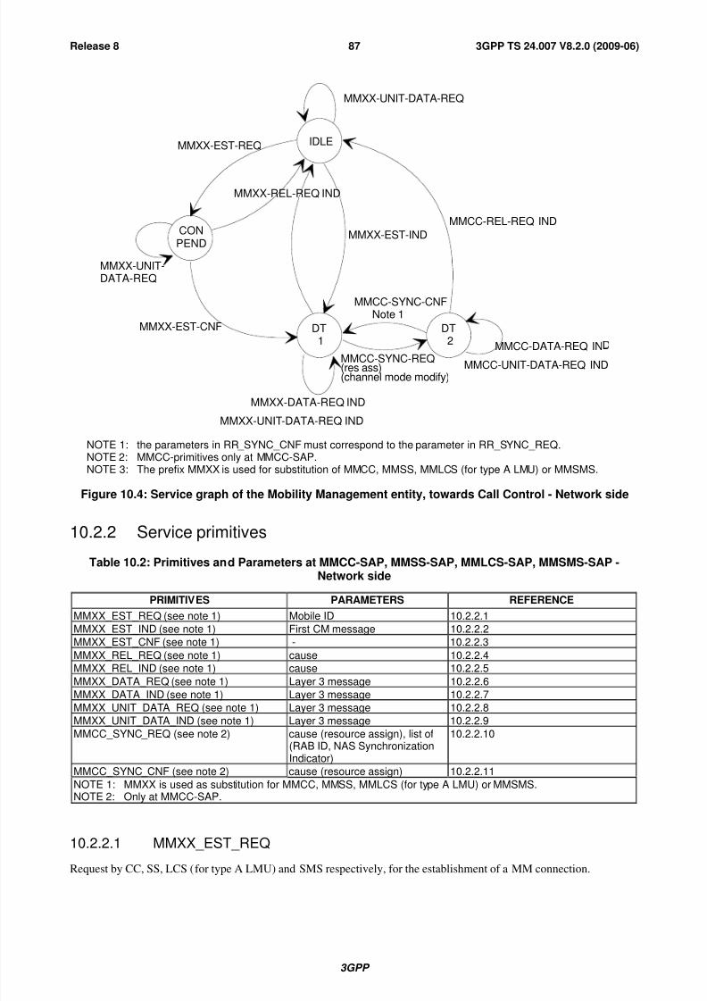
8/3/2019 3GPP TS 24007-V8.2.0
http://slidepdf.com/reader/full/3gpp-ts-24007-v820 87/149
3GPP
3GPP TS 24.007 V8.2.0 (2009-06)87Release 8
IDLE
CONPEND
MMXX-UNIT-DATA-REQ
MMCC-REL-REQ IND
MMXX-EST-REQ
MMXX-REL-REQ IND
MMXX-EST-IND
MMCC-SYNC-REQ(res ass)(channel mode modify)
MMXX-DATA-REQ IND
MMXX-UNIT-DATA-REQ IND
MMCC-DATA-REQ INMMCC-UNIT-DATA-REQ IND
MMXX-EST-CNF
MMXX-UNIT-DATA-REQ
DT1
MMCC-SYNC-CNFNote 1
DT2
NOTE 1: the parameters in RR_SYNC_CNF must correspond to the parameter in RR_SYNC_REQ.NOTE 2: MMCC-primitives only at MMCC-SAP.NOTE 3: The prefix MMXX is used for substitution of MMCC, MMSS, MMLCS (for type A LMU) or MMSMS.
Figure 10.4: Service graph of the Mobility Management entity, towards Call Control - Network side
10.2.2 Service primitives
Table 10.2: Primitives and Parameters at MMCC-SAP, MMSS-SAP, MMLCS-SAP, MMSMS-SAP -Network side
PRIMITIVES PARAMETERS REFERENCE
MMXX_EST_REQ (see note 1) Mobile ID 10.2.2.1
MMXX_EST_IND (see note 1) First CM message 10.2.2.2
MMXX_EST_CNF (see note 1) - 10.2.2.3
MMXX_REL_REQ (see note 1) cause 10.2.2.4
MMXX_REL_IND (see note 1) cause 10.2.2.5
MMXX_DATA_REQ (see note 1) Layer 3 message 10.2.2.6
MMXX_DATA_IND (see note 1) Layer 3 message 10.2.2.7
MMXX_UNIT_DATA_REQ (see note 1) Layer 3 message 10.2.2.8
MMXX_UNIT_DATA_IND (see note 1) Layer 3 message 10.2.2.9
MMCC_SYNC_REQ (see note 2) cause (resource assign), list of(RAB ID, NAS SynchronizationIndicator)
10.2.2.10
MMCC_SYNC_CNF (see note 2) cause (resource assign) 10.2.2.11
NOTE 1: MMXX is used as substitution for MMCC, MMSS, MMLCS (for type A LMU) or MMSMS.NOTE 2: Only at MMCC-SAP.
10.2.2.1 MMXX_EST_REQ
Request by CC, SS, LCS (for type A LMU) and SMS respectively, for the establishment of a MM connection.
8/3/2019 3GPP TS 24007-V8.2.0
http://slidepdf.com/reader/full/3gpp-ts-24007-v820 88/149
3GPP
3GPP TS 24.007 V8.2.0 (2009-06)88Release 8
10.2.2.2 MMXX_EST_IND
Indication by the MM sublayer that a MM connection is established.
10.2.2.3 MMXX_EST_CNF
Confirmation of the MM connection establishment by the MM sublayer.
10.2.2.4 MMXX_REL_REQ
Request by CC, SS, LCS (for type A LMU) or SMS respectively, for the release of the MM connection.
10.2.2.5 MMXX_REL_IND
Indication by the MM sublayer that a MM connection has been released.
10.2.2.6 MMXX_DATA_REQ
Request by the CC, SS, LCS (for type A LMU) or SMS entities for acknowledged control-data transmission.
10.2.2.7 MMXX_DATA_IND
Indication used by MM to transfer the received acknowledged control-data to the CC, SS, LCS (for type A LMU) or
SMS entities.
10.2.2.8 MMXX_UNIT_DATA_REQ
Request used by the CC, SS, LCS (for type A LMU) or SMS entities for unacknowledged control-data transmission.
10.2.2.9 MMXX_UNIT_DATA_IND
Indication used by MM to transfer the received unacknowledged control-data to the CC, SS, LCS (for type A LMU) or
SMS entities.
10.2.2.10 MMCC_SYNC_REQ
Request used by the CC entity to synchronize with the MM entity (resource assign).
In Iu mode, the CC entity includes the list of the RAB IDs and, optionally, the NAS Synchronization Indicators
associated with the requested radio bearers.
10.2.2.11 MMCC_SYNC_CNF
Confirmation used by the MM to inform the CC entity that synchronization is completed (resource assign).
10.3 Services provided by radio resource management entity forGPRS services
10.3.1 Service primitives for GRR-SAP
The GRR-SAP service primitives are defined in 3GPP TS 44.064 [11a]
[Table 10.3.1, and chapters 10.3.1.1 - 10.3.1.5 are Void]

8/3/2019 3GPP TS 24007-V8.2.0
http://slidepdf.com/reader/full/3gpp-ts-24007-v820 89/149
3GPP
3GPP TS 24.007 V8.2.0 (2009-06)89Release 8
10.3.2 Service primitives for GMMRR-SAP
Table 10.3.2: Primitives and Parameters at GMMRR-SAP - network side
PRIMITIVE PARAMETER(message, info elements of message, other
parameters)
REFERENCE
GMMRR-PAGE-REQ TLLI, IMSI, CI or CI-list or RAI, priority 10.3.2.1
10.3.2.1 GMMRR-PAGE-REQ
Request by GMM to send a RR-paging message to the mobile station.
10.4 Services provided by the LLC entity for GPRS services
10.4.1 Service primitives for LLGMM-SAP
Table 10.4.1: Primitives and Parameters at GRR-SAP - network side
PRIMITIVE PARAMETER(message, info elements of message, other
parameters)
REFERENCE
LLGMM-ASSIGN-REQ newTLLI, oldTLLI, Kc, Algorithm 10.4.1.1
LLGMM-SUSPEND-REQ TLLI, page 10.4.1.3
LLGMM-RESUME-REQ TLLI 10.4.1.4
LLGMM-PAGE-IND TLLI 10.4.1.5
LLGMM-PAGE-RESP-IND TLLI 10.4.1.6
LL-UNITDATA-REQ TLLI, SMM-PDU, protect, cipher 10.4.1.9
LL-UNITDATA-IND TLLI, SMM-PDU, cipher 10.4.1.10
LLGMM-STATUS-IND TLLI, cause 10.4.1.11
10.4.1.1 LLGMM-ASSIGN-REQ
A new TLLI and/or a ciphering key and/or a ciphering algorithm is assigned to the LL sublayer. Also an old TLLI can
be unassigned.
10.4.1.2 Void
10.4.1.3 LLGMM-SUSPEND-REQ
All LLC links will cease sending PDUs. The parameter page indicates that data shall be sent if available and thereforepaging shall be needed. Or the cause indicates that data shall not be sent until a RESUME-REQ is received.
10.4.1.4 LLGMM-RESUME-REQ
Normal LLC frame sending and reception is possible again.
10.4.1.5 Void
10.4.1.6 Void
10.4.1.7 LLGMM-PAGE-IND
Requires to send a paging message to the mobile station.

8/3/2019 3GPP TS 24007-V8.2.0
http://slidepdf.com/reader/full/3gpp-ts-24007-v820 90/149
3GPP
3GPP TS 24.007 V8.2.0 (2009-06)90Release 8
10.4.1.8 LLGMM-PAGE-RESP-IND
A paging response has been received from the mobile.
10.4.1.9 LL-UNITDATA-REQ
Request to send a SMM message in unacknowledged mode to the peer entity.
10.4.1.10 LL-UNITDATA-IND
A SMM message in unacknowledged mode has been received from the peer entity.
10.4.1.11 LLGMM-STATUS-IND
Indication used by LLC to transfer lower layer failures to the GMM sublayer.
10.4.2 Service primitives for LLSMS-SAP
Table 10.4.2: Primitives and Parameters at LLSMS-SAP - network side
PRIMITIVE PARAMETER(message, info elements of message, other
parameters)
REFERENCE
LL-UNITDATA-REQ TLLI, SMS-CP-PDU, protect, cipher 10.4.2.1
LL-UNITDATA-IND TLLI, SMS-CP-PDU 10.4.2.2
10.4.2.1 LL-UNITDATA-REQ
An LLC UI frame will be sent to the peer entity.
10.4.2.2 LL-UNITDATA-IND
An LLC UI frame has been received from the peer entity.
10.5 Services provided by the GMM for GPRS services
The GPRS Mobility Management (GMM) sublayer provides services to the Session Management (SM) entity and the
Short Message Service Support (SMS) entity for message transfer.
10.5.1 Service primitives for GMMSM-SAP
Table 10.5.1: Primitives and Parameters at GMMSM-SAP - network side
PRIMITIVE PARAMETER(message, info elements of message, other
parameters)
REFERENCE
GMMSM-RELEASE-IND - 10.5.1.1
GMMSM-UNITDATA-REQ SM-PDU 10.5.1.2
GMMSM-UNITDATA-IND SM-PDU 10.5.1.3
10.5.1.1 GMMSM-RELEASE-IND
The GPRS mobility management informs the session management that the MS has been GPRS detached, e.g. by timer
expiry, and therefore the PDP contexts are not valid anymore.

8/3/2019 3GPP TS 24007-V8.2.0
http://slidepdf.com/reader/full/3gpp-ts-24007-v820 91/149
3GPP
3GPP TS 24.007 V8.2.0 (2009-06)91Release 8
10.5.1.2 GMMSM-UNITDATA-REQ
The GMM is requested to forward a SM PDU to LLC in order to send it in unacknowledged more to the peer entity.
10.5.1.3 GMMSM-UNITDATA-IND
The GMM forwards a SM PDU, which has been received in unacknowledged mode via LLC from the peer entity.
10.5.2 Service primitives for PMMSMS-SAP
Table 10.5.2: Primitives and Parameters at PMMSMS-SAP - Network side
PRIMITIVES PARAMETERS(message, info elements ofmessage, other parameters)
REFERENCE
PMMSMS_REL_REQ - 10.5.2.1
PMMSMS_ERROR _IND cause 10.5.2.2
PMMSMS_UNITDATA_REQ SMS-PDU 10.5.2.3
PMMSMS_UNITDATA_IND SMS-PDU 10.5.2.4
10.5.2.1 PMMSMS_REL_REQ
The GMM is requested to release of a PS signalling connection.
10.5.2.2 PMMSMS_ERROR_IND
The GMM indicates that a PS signalling connection has been released.
10.5.2.3 PMMSMS_UNITDATA_REQ
The GMM is requested to forward a SMS PDU in order to send to the peer entity.
10.5.2.4 PMMSMS_UNITDATA_IND
Indication used by GMM to transfer the received data to the GSMS entities.
10.5.3 Service primitives for GMMSS-SAP
Table 10.5.3: Primitives and Parameters at GMMSS-SAP - network side
PRIMITIVE PARAMETER(message, info elements of message, other
parameters)
REFERENCE
GMMSS-RELEASE-IND - 10.5.3.1
GMMSS-UNITDATA-REQ SS-PDU 10.5.3.2
GMMSS-UNITDATA-IND SS-PDU 10.5.3.3
10.5.3.1 GMMSS-RELEASE-IND
The GPRS mobility management informs the Supplementary service that the MS has been GPRS detached, e.g. by
timer expiry.
10.5.3.2 GMMSS-UNITDATA-REQ
The GMM is requested to forward a SS PDU to lower layer in order to send it to the peer entity.
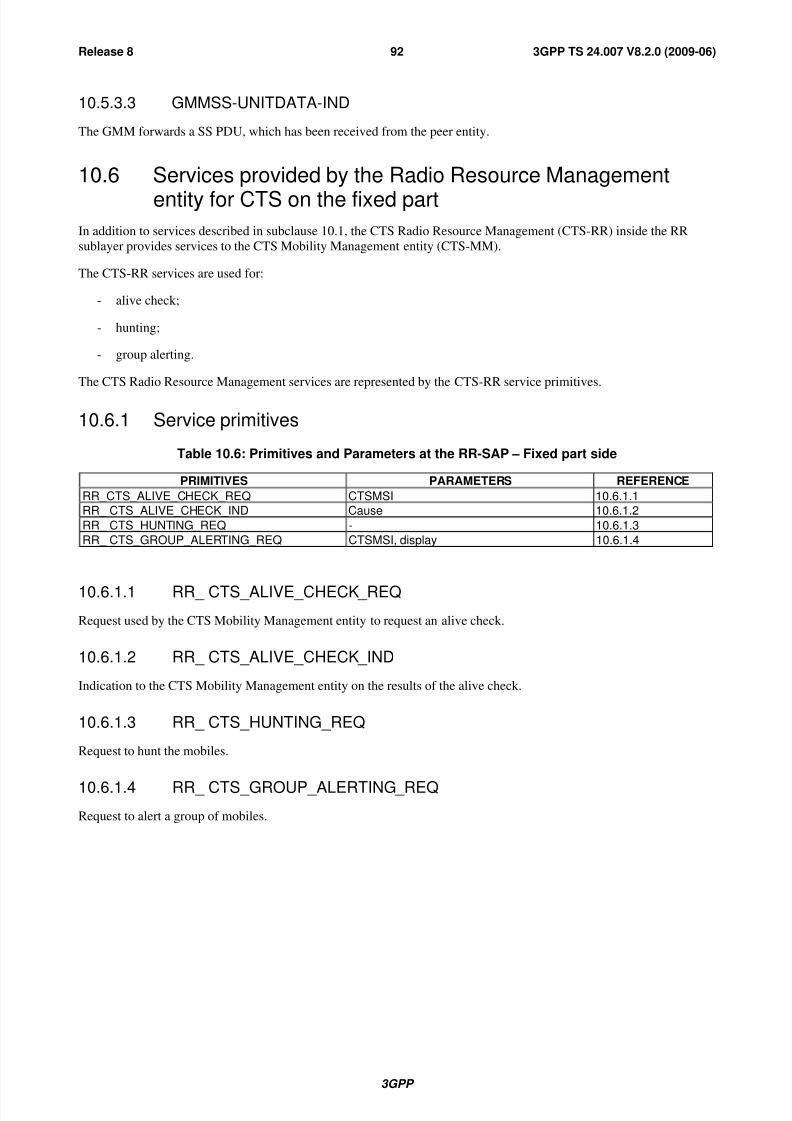
8/3/2019 3GPP TS 24007-V8.2.0
http://slidepdf.com/reader/full/3gpp-ts-24007-v820 92/149
3GPP
3GPP TS 24.007 V8.2.0 (2009-06)92Release 8
10.5.3.3 GMMSS-UNITDATA-IND
The GMM forwards a SS PDU, which has been received from the peer entity.
10.6 Services provided by the Radio Resource Management
entity for CTS on the fixed partIn addition to services described in subclause 10.1, the CTS Radio Resource Management (CTS-RR) inside the RR
sublayer provides services to the CTS Mobility Management entity (CTS-MM).
The CTS-RR services are used for:
- alive check;
- hunting;
- group alerting.
The CTS Radio Resource Management services are represented by the CTS-RR service primitives.
10.6.1 Service primitives
Table 10.6: Primitives and Parameters at the RR-SAP – Fixed part side
PRIMITIVES PARAMETERS REFERENCE
RR_CTS_ALIVE_CHECK_REQ CTSMSI 10.6.1.1
RR_ CTS_ALIVE_CHECK_IND Cause 10.6.1.2
RR_ CTS_HUNTING_REQ - 10.6.1.3
RR_ CTS_GROUP_ALERTING_REQ CTSMSI, display 10.6.1.4
10.6.1.1 RR_ CTS_ALIVE_CHECK_REQ
Request used by the CTS Mobility Management entity to request an alive check.
10.6.1.2 RR_ CTS_ALIVE_CHECK_IND
Indication to the CTS Mobility Management entity on the results of the alive check.
10.6.1.3 RR_ CTS_HUNTING_REQ
Request to hunt the mobiles.
10.6.1.4 RR_ CTS_GROUP_ALERTING_REQ
Request to alert a group of mobiles.
8/3/2019 3GPP TS 24007-V8.2.0
http://slidepdf.com/reader/full/3gpp-ts-24007-v820 93/149
3GPP
3GPP TS 24.007 V8.2.0 (2009-06)93Release 8
11 L3 Messages
This clause specifies the generic methods used in the layer 3 protocol specifications to describe messages. It define in
particular a generic message structure, that of the "standard L3 messages". Not all messages in layer 3 protocols followthis structure, but many do, and this clause specifies how to interpret the standard description.
This clause also addresses basic aspects of the handling of messages received but not compliant with the allowed
structure. In most cases, only the conditions that lead to the diagnosis of an error are described. The reaction of an entity
receiving a message leading to such a diagnosis is in general specified for each protocol in the relevant protocol
specification.
11.1 General
11.1.1 Messages
For all concerned protocols, concrete messages are bit strings of variable length, formally a succession of a finite,
possibly null, number of bits (i.e., elements of the set {"0", "1"}), with a beginning and an end.
The services provided by lower layers includes the transmission of such bit strings.
Considered as messages, these bit strings follow some structure (the syntax), enabling to organize bits in informationpieces of a different meaning level.
The term message is used as well for a concrete message (i.e., a bit-string, as defined by the giving of all its bits, in
practice appearing at one point of time in a concrete dialog), as for a class of concrete messages sharing a common
structure. A concrete message is an instance of the corresponding class of messages. Message classes can be described
as sets of potential bit strings, and of a common structure, enabling in particular to identify parts meaningful for the co -operation functions the protocol supports.
In general, in the rest of the clause as in the protocol specifications, the term message will be used to refer to the class. It
may be used, when the context prevents ambiguity, to refer to a message instance (e.g., a received is usually a message
instance). In the rest of this clause, the term message instance will be used when needed to refer unambiguously to
specific concrete message, i.e. to a specific bit string.
A message (message class) can be described directly as a set of bit strings, using the formal notation described inAnnex B.
A message can also be described as a standard L3 message, in which case the interpretation of the message description
in term of a set of bit strings is specified in the next sub-clauses.
In all cases, structuring messages is based on the underlying bit string. Thus, the following terms are used:
- a part of a message instance is a sub-string of the corresponding string; a part of a message (as a class) is
described by a definition applicable to all instances; a part of a message then is both a structural attribute of the
message as a class, and a set of sub-strings, composed of the sub-strings obtained by applying the definition toeach possible instance; for instance, « the first octet » of a message instance is defined from the moment its
length is greater than 8, and is the sub-string composed of the first 8 bits of the message instance; the « first
octet » of a message as a class is the structural definition given above, and the set of all 8-bit octet strings that
can be obtained as the first octet of one instance of the class;
- "part A follows part B" means that in the message the sub-string corresponding to part B is concatenated with the
sub-string of part B;
- the length of a message instance, or of part of message instance, is the number of bits of the corresponding sub
string; rigorously speaking, a message as a class (or a part seen as a class) has a length only if all the
corresponding instances have the same length; by extension, sentences such as « a message as a length in the
range so and so » means that the length of an instances of the class always fall in the range.

8/3/2019 3GPP TS 24007-V8.2.0
http://slidepdf.com/reader/full/3gpp-ts-24007-v820 94/149
3GPP
3GPP TS 24.007 V8.2.0 (2009-06)94Release 8
11.1.2 Octets
In many places, a message is described as a succession of octets. An octet is generally a succession of 8 bits. Unless
otherwise indicated, the term octet is used more restrictively to refer to a part of message, defined when considering a
message as a succession of octets, e.g., the first 8 bits of a message, or the 17th to the 23rd, form an octet, but not the
second bit to the 9th.
Unless specified otherwise, the numbering conventions are the following:
- Octets in a message or in a part are numbered from 1 onward, starting at the beginning of the bit string. This
numbering can be strictly applied only for message instances, and for the first part of a message structurally
identical for all instances.
- Bits in octets are numbered from 8 down to 1, starting at the beginning of the octet.
- When represented as tables showing the different bit positions, octets are presented in the natural occidental
order, i.e., from the top of a page downward. Bits in octets are presented with the first bit on the left of the page.
11.1.3 Integer
In many places, message parts are described as encoding integers. Two generic encoding are defined in this subclause.
11.1.3.1 Binary
A message part is said to encode in binary an integer to indicate that concrete strings are mapped, for some usage, on
the set of non signed integers with the following rule:
- Let k denote the length of the bit string, and let b(i) denote an integer of value 0 if the ith
bit in the string is "0",and 1 otherwise. The encoded integer n respects the equation:
n b ik i
i tok
( )21
1
11.1.3.2 2-complement binary
A message part is said to encode in 2-complement binary an integer to indicate that concrete strings are mapped, for
some usage, on the set of signed integers with the following rule:
- Let k denote the length of the bit string, and let b(i) denote an integer of value 0 if the ith
bit in the string is "0",
and 1 otherwise. The encoded integer n respects the equation:
if then
else
b n b i
n b i
k i
i tok
k i
i tok
k
( ) ( )
( )
1 0 2
2 2
1
1
1
1
11.1.4 Spare parts
In some cases the specification is that which message instances can be accepted by a receiver comprise more that the
legal message instances that can be sent. One example of this is the notion of spare bit. A spare bit has to send as the
value indicated in the specification (typically 0), but can be accepted as a 0 or a 1 by the receiver without error
diagnosis. A spare field is a field composed entirely of spare bits.

8/3/2019 3GPP TS 24007-V8.2.0
http://slidepdf.com/reader/full/3gpp-ts-24007-v820 95/149
3GPP
3GPP TS 24.007 V8.2.0 (2009-06)95Release 8
11.2 Standard L3 messages
11.2.1 Components of a standard L3 message
A standard L3 message consists of an imperative part, itself composed of a header and the rest of imperative part,
followed by a non-imperative part. Both the non-header part of the imperative part and the non-imperative part arecomposed of successive parts referred as standard information elements.
11.2.1.1 Format of standard information elements
A standard IE may have the following parts, in that order:
- an information element identifier (IEI);
- a length indicator (LI);
- a value part.
A standard IE has one of the formats shown in table 11.1:
Table 11.1: Formats of information elements
Format Meaning IEI present LI present Value part present
T Type only yes no no
V Value only no no yes
TV Type and Value yes no yes
LV Length and Value no yes yes
TLV Type, Length and Value yes yes yes
LV-E Length and Value no yes yes
TLV-E Type, Length and Value yes yes yes
Some IEs may appear in the structure, but not in all instances of messages. An IE is then said to be present or notpresent in the message instance. If an IE is not present in a message instance, none of the three parts is present.Otherwise, parts must be present according to the IE format.
In the message structure, an IE that is allowed not to be present in all message instances is said not to be mandatory.
Other IEs are said to be mandatory.
LV-E and TLV-E are used for EPS Mobility Management (EMM) and EPS Session Management (ESM) only.
11.2.1.1.1 Information element type and value part
Every standard IE has an information element type which determines the values possible for the value part of the IE,
and the basic meaning of the information. The information element type describes only the value part. Standard IEs of
the same information element type may appear with different formats. The format used for a given standard IE in agiven message is specified within the description of the message.
The value part of a standard IE either consists of a half octet or one or more octets; the value part of a standard IE with
format LV or TLV consists of an integral number of octets, between 0 and 255 inclusive; it then may be empty, i.e.,
consist of zero octets; if it consists of a half octet and has format TV, its IEI consists of a half octet, too. For LV-E and
TLV-E, the value part of a standard IE consists of an integral number of octets, between 0 and 65535 inclusive. The
value part of a standard IE may be further structured into parts, called fields.
11.2.1.1.2 Length indicator
For LV or TLV, the length indicator (LI) of a standard IE consists of one octet. For LV-E and TLV-E, the LI of a
standard IE consists of two octets where bit 8 of octet n contains the most significant bit and bit 1 of octet n+1 contains
the least significant bit (refer to figure 11.9 in subclause 11.2.1.1.4 for the relative ordering of the 2 octets). The LIcontains the binary encoding of the number of octets of the IE value part. The LI of a standard IE with empty value part
indicates 0 octets. Standard IE of an information element type such that the possible values may have different values
must be formatted with a length field, i.e., LV, TLV, LV-E or TLV-E.
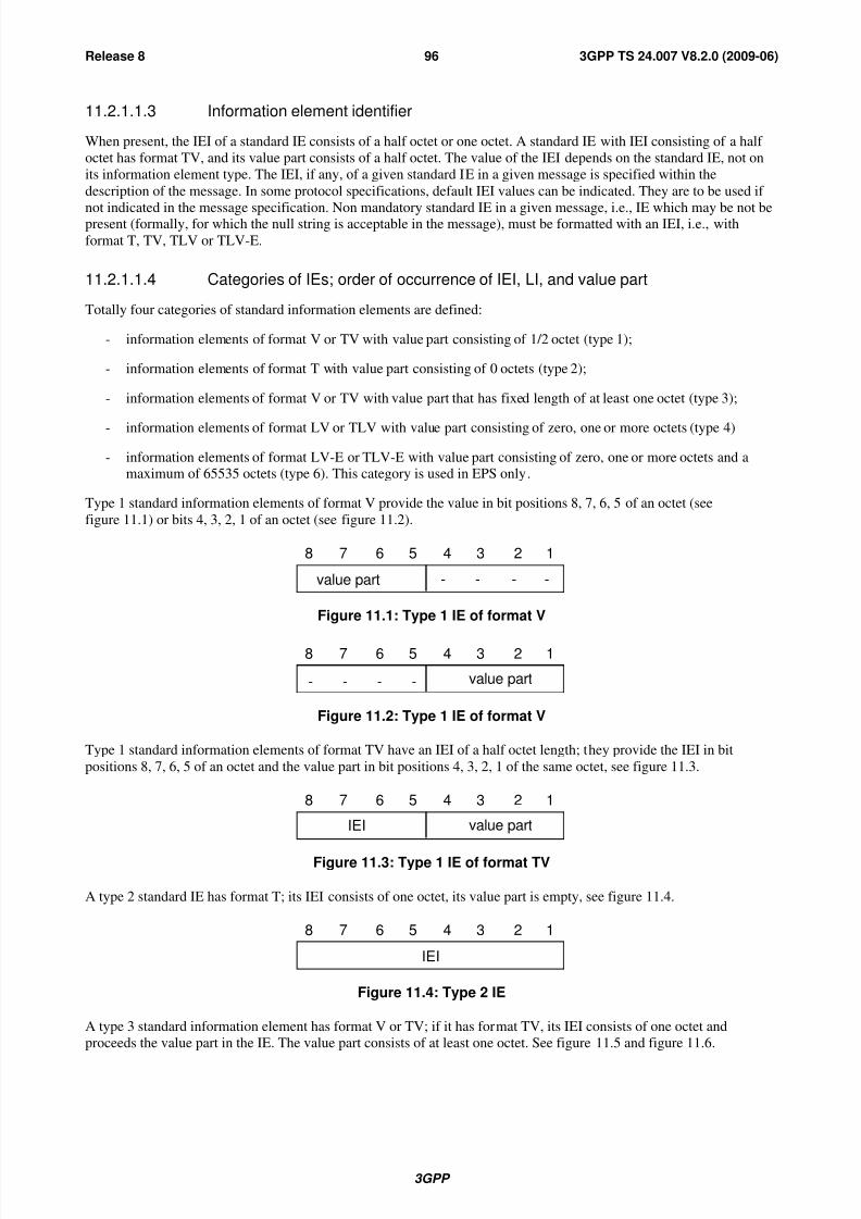
8/3/2019 3GPP TS 24007-V8.2.0
http://slidepdf.com/reader/full/3gpp-ts-24007-v820 96/149
3GPP
3GPP TS 24.007 V8.2.0 (2009-06)96Release 8
11.2.1.1.3 Information element identifier
When present, the IEI of a standard IE consists of a half octet or one octet. A standard IE with IEI consisting of a half
octet has format TV, and its value part consists of a half octet. The value of the IEI depends on the standard IE, not on
its information element type. The IEI, if any, of a given standard IE in a given message is specified within the
description of the message. In some protocol specifications, default IEI values can be indicated. They are to be used if
not indicated in the message specification. Non mandatory standard IE in a given message, i.e., IE which may be not bepresent (formally, for which the null string is acceptable in the message), must be formatted with an IEI, i.e., with
format T, TV, TLV or TLV-E.
11.2.1.1.4 Categories of IEs; order of occurrence of IEI, LI, and value part
Totally four categories of standard information elements are defined:
- information elements of format V or TV with value part consisting of 1/2 octet (type 1);
- information elements of format T with value part consisting of 0 octets (type 2);
- information elements of format V or TV with value part that has fixed length of at least one octet (type 3);
- information elements of format LV or TLV with value part consisting of zero, one or more octets (type 4)
- information elements of format LV-E or TLV-E with value part consisting of zero, one or more octets and amaximum of 65535 octets (type 6). This category is used in EPS only.
Type 1 standard information elements of format V provide the value in bit positions 8, 7, 6, 5 of an octet (see
figure 11.1) or bits 4, 3, 2, 1 of an octet (see figure 11.2).
8 7 6 5 4 3 2 1
- - - -value part
Figure 11.1: Type 1 IE of format V
8 7 6 5 4 3 2 1
- - - - value part
Figure 11.2: Type 1 IE of format V
Type 1 standard information elements of format TV have an IEI of a half octet length; they provide the IEI in bit
positions 8, 7, 6, 5 of an octet and the value part in bit positions 4, 3, 2, 1 of the same octet, see figure 11.3.
8 7 6 5 4 3 2 1
value partIEI
Figure 11.3: Type 1 IE of format TV
A type 2 standard IE has format T; its IEI consists of one octet, its value part is empty, see figure 11.4.
8 7 6 5 4 3 2 1
IEI
Figure 11.4: Type 2 IE
A type 3 standard information element has format V or TV; if it has format TV, its IEI consists of one octet and
proceeds the value part in the IE. The value part consists of at least one octet. See figure 11.5 and figure 11.6.

8/3/2019 3GPP TS 24007-V8.2.0
http://slidepdf.com/reader/full/3gpp-ts-24007-v820 97/149
3GPP
3GPP TS 24.007 V8.2.0 (2009-06)97Release 8
8 7 6 5 4 3 2 1
value
part
octet n
octet n + k
Figure 11.5: Type 3 IE of format V (k = 0, 1, 2, ...)
value
part
octet n
octet n + k
8 7 6 5 4 3 2 1
IEI
octet n + 1
Figure 11.6: Type 3 IE of format TV (k = 1, 2, ...)
A type 4 standard information element has format LV or TLV. Its LI precedes the value part, which consists of zero,
one, or more octets; if present, its IEI has one octet length and precedes the LI. See figure 11.7 and figure 11.8.
value
part
octet n
octet n + k
8 7 6 5 4 3 2 1
LI
octet n + 1
Figure 11.7: Type 4 IE of format LV (k = 0, 1, 2, ...)
value
part
octet n + 1
octet n + k
LI
octet n + 2
octet n
8 7 6 5 4 3 2 1
IEI
Figure 11.8: Type 4 IE of format TLV (k = 1, 2, ...)
A type 6 standard information element has format TLV-E. The IEI has one octet length and precedes the LI of 2 octetsand the value part which consists of zero, one or up to 65535 octets. See figure 11.9 and figure 11.10.
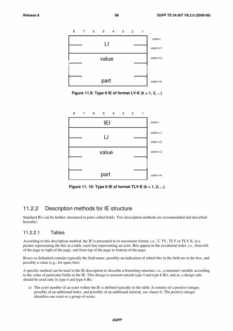
8/3/2019 3GPP TS 24007-V8.2.0
http://slidepdf.com/reader/full/3gpp-ts-24007-v820 98/149
3GPP
3GPP TS 24.007 V8.2.0 (2009-06)98Release 8
LIoctetn+1
octetn+k
octetn
octetn+2value
part
8 7 6 5 4 3 2 1
Figure 11.9: Type 6 IE of format LV-E (k = 1, 2, ...)
IEI
LI
octet n
octet n+2
octet n+k
octet n+1
octet n+3value
part
8 7 6 5 4 3 2 1
Figure 11. 10: Type 6 IE of format TLV-E (k = 1, 2, ...)
11.2.2 Description methods for IE structure
Standard IEs can be further structured in parts called fields. Two description methods are recommended and described
hereafter.
11.2.2.1 Tables
According to this description method, the IE is presented in its maximum format, i.e., T, TV, TLV or TLV-E, in a
picture representing the bits in a table, each line representing an octet. Bits appear in the occidental order, i.e., from left
of the page to right of the page, and from top of the page to bottom of the page.
Boxes so delimited contains typically the field name, possibly an indication of which bits in the field are in the box, and
possibly a value (e.g., for spare bits).
A specific method can be used in the IE description to describe a branching structure, i.e., a structure variable according
to the value of particular fields in the IE. This design is unusual outside type 4 and type 6 IEs, and as, a design rule,
should be used only in type 4 and type 6 IEs.
a) The octet number of an octet within the IE is defined typically in the table. It consists of a positive integer,
possibly of an additional letter, and possibly of an additional asterisk, see clause f). The positive integer
identifies one octet or a group of octets.

8/3/2019 3GPP TS 24007-V8.2.0
http://slidepdf.com/reader/full/3gpp-ts-24007-v820 99/149
3GPP
3GPP TS 24.007 V8.2.0 (2009-06)99Release 8
b) Each octet group is a self contained entity. The internal structure of an octet group may be defined in alternative
ways.
c) An octet group is formed by using some extension mechanism. The preferred extension mechanism is to extend
an octet (N) through the next octet(s) (Na, Nb, etc.) by using bit 8 in each octet as an extension bit.
- The bit value "0" indicates that the octet group continues through to the next octet. The bit value "1" indicates
that this octet is the last octet of the group. If one octet (Nb) is present, the preceding octets (N and Na) shallalso be present.
- In the format descriptions of the individual information elements, bit 8 is marked "0/1 ext" if another octetfollows. Bit 8 is marked "1 ext" if this is the last octet in the extension domain.
- Additional octets may be defined in later versions of the protocols ("1 ext" changed to "0/1 ext") and
equipments shall be prepared to receive such additional octets; the contents of these octets shall be ignored.
However the length indicated in the formal description of the messages and of the individual information
elements only takes into account this version of the protocols.
d) In addition to the extension mechanism defined above, an octet (N) may be extended through the next octet(s)(N+1, N+2 etc.) by indications in bits 7-1 (of octet N).
e) The mechanisms in c) and d) may be combined.
f) Optional octets are marked with asterisks (*). As a design rule, the presence or absence of an optional octet
should be determinable from information in the IE and preceding the optional octet. Care should be taken not to
introduce ambiguities with optional octets.
g) At the end of the IE, additional octets may be added in later versions of the protocols also without using the
mechanisms defined in c) and d). Equipments shall be prepared to receive such additional octets; the contents of
these octets shall be ignored. However the length indicated in the formal description of the messages and of the
individual information elements only takes into account this version of the protocols.
11.2.2.1.1 Compact notation
The compact notation described in Annex B can be used to describe the value part of a standard IE. This method is
recommended for complex structures, or for a branching structure not respecting octet boundaries.
11.2.3 Imperative part of a standard L3 message
The imperative part of a standard L3 message is composed of a header possibly followed by mandatory standard IEs
having the format V, LV or LV-E.
11.2.3.1 Standard L3 message header
The header of a standard L3 message is composed of two octets, and structured in three main parts, the protocol
discriminator (1/2 octet), a message type octet, and a half octet used in some cases as a Transaction Identifier, in some
other cases as a sub-protocol discriminator, and called skip indicator otherwise.
For the EPS protocols EMM and ESM, a standard L3 message can be either a plain NAS message or a security
protected NAS message:
- The header of a plain NAS message is composed of two or three octets, and structured in four main parts, the
protocol discriminator (1/2 octet), a half octet used in some cases as security header type and in other cases as an
EPS bearer identity (1/2 octet), a message type octet, and one octet included in some cases and used as a
procedure transaction identity (PTI). If the procedure transaction identity is present, it is preceding the message
type octet.
- The header of a security protected NAS message is composed of six octets, and structured in four main parts, the
protocol discriminator (1/2 octet), a half octet used as security header type, a message authentication code of
four octets, and a sequence number of one octet. This header is followed by a complete plain NAS message (i.e.including the header of this plain NAS message).

8/3/2019 3GPP TS 24007-V8.2.0
http://slidepdf.com/reader/full/3gpp-ts-24007-v820 100/149
3GPP
3GPP TS 24.007 V8.2.0 (2009-06)100Release 8
11.2.3.1.1 Protocol discriminator
Bits 1 to 4 of the first octet of a standard L3 message contain the protocol discriminator (PD) information element. The
PD identifies the L3 protocol to which the standard layer 3 message belongs. The correspondence between L3 protocols
and PDs is one-to-one.
For future evolution an extension mechanism is foreseen which allows the use of protocol discriminators with one octet
length, where bits 4 to one are coded as 1 1 1 0. Messages of such protocols may not be standard L3 messages. Inparticular, the rest of the header may not respect the structure described in this sub-clause.
The PD can take the following values:
Table 11.2: Protocol discriminator values
bits 4 3 2 1
0 0 0 0 group call control
0 0 0 1 broadcast call control
0 0 1 0 EPS session management messages
0 0 1 1 call control; call related SS messages
0 1 0 0 GPRS Transparent Transport Protocol (GTTP)
0 1 0 1 mobility management messages0 1 1 0 radio resources management messages
0 1 1 1 EPS mobility management messages
1 0 0 0 GPRS mobility management messages
1 0 0 1 SMS messages
1 0 1 0 GPRS session management messages
1 0 1 1 non call related SS messages
1 1 0 0 Location services specified in 3GPP TS 44.071 [8a]
1 1 1 0 reserved for extension of the PD to one octet length
1 1 1 1 used by tests procedures described in 3GPP TS 44.014 [5a], 3GPP TS34.109 [17a] and 3GPP TS 36.509 [26].
If the network receives, on a SAP where it expects standard L3 messages, a message with a protocol discriminator
different from those specified in table 11.2, the network may ignore the message or initiate the channel release
procedure defined in 3GPP TS 44.018 [6b].
If the Mobile Station receives, on a SAP where it expects standard L3 messages, a standard L3 message with a protocol
discriminator different from those specified in table 11.2, or for a protocol that it does not support, the Mobile Station
shall ignore the message.
11.2.3.1.2 Skip indicator
Bits 5 to 8 of octet 1 of a standard L3 message may be used differently, depending on the protocol and the SAP. The use
of this half-octet is consistent for a given PD and SAP. One possibility is that this half-octet contains the skip indicator.
Unless otherwise specified in the protocol, the skip indicator IE is a spare field.
11.2.3.1.3 Transaction identifier
A L3 protocol may define that bits 5 to 8 of octet 1 of a standard L3 message of the protocol contains the transaction
identifier (TI). The TI allows to distinguish up to 16 different bi-directional messages flows for a given PD and a given
SAP. Such a message flow is called a transaction.
An extension mechanism for TI is also defined. This mechanism allows to distinguish up to 256 different bi-directional
messages flows for a given PD and a given SAP. The extension mechanism shall not be used unless explicitly stated in
the core specification(s) for the protocol. The TI IE is coded as shown in figure 11.9 and table 11.3. It is composed of
the TI value and the TI flag.
The TI value and the TI flag occupy bits 5 - 7 and bit 8 of the first octet respectively.
The extended TI shall not be used unless TI values of 7 or greater are needed.
Where the extended TI is used, the TI IE includes a second octet. The TI value in the first octet is ignored, and the TI
value is encoded in bits 7-1 of the second octet.

8/3/2019 3GPP TS 24007-V8.2.0
http://slidepdf.com/reader/full/3gpp-ts-24007-v820 101/149
3GPP
3GPP TS 24.007 V8.2.0 (2009-06)101Release 8
NOTE: In other specifications, in respect to error handling, there are references to TI value "111". This refers to
the binary encoding of bits 5 – 7 in octet 1. For protocols which do not use the extended TI this '111'
encoding is still handled as an error case.Transactions are dynamically created, and their TI value is
assigned at creation time. TI values are assigned by the side of the interface initiating a transaction. At the
beginning of a transaction a free TI value (i.e., a value not yet used for the given PD, the given SAP, and
with the given initiator) is chosen and assigned to this transaction. It then remains fixed for the lifetime of
the transaction. After a transaction ends, the associated TI value is free and may be reassigned to a latertransaction.
Two identical TI values may be used when each value pertains to a transaction initiated by the different sides of the
interface. In this case the TI flag shall avoid ambiguity. The transaction identifier flag can take the values "0" or "1".
The TI flag is used to identify which side of the interface initiated the transaction. A message has a TI flag set to "0"
when it belongs to transaction initiated by its sender, and to "1" otherwise.
Hence the TI flag identifies who allocated the TI value for this transaction and the only purpose of the TI flag is to
resolve simultaneous attempts to allocate the same TI value.
The TI extension mechanism may in future evolution of the L3 protocols be further extended by setting the EXT flag in
octet 2 to "0" (see figure 11.9).
8 7 6 5 4 3 2 1
TI
flagTIO - - - - Octet 1
1EXT
TIEOctet 2
*
Figure 11.9: Transaction identifier

8/3/2019 3GPP TS 24007-V8.2.0
http://slidepdf.com/reader/full/3gpp-ts-24007-v820 102/149
3GPP
3GPP TS 24.007 V8.2.0 (2009-06)102Release 8
Table 11.3: Transaction identifier
TI flag (octet 1)Bit80 The message is sent from the side that originates the TI1 The message is sent to the side that originates the TI
TIO (octet 1)Bits7 6 50 0 0 TI value 00 0 1 - - 10 1 0 - - 20 1 1 - - 31 0 0 - - 41 0 1 - - 51 1 0 - - 61 1 1 The TI value is given by the TIE in octet 2
TIE (octet 2)Bits 7-10000000000000100000100000011000010000001010000110
Reserved.
All other values The TI value is the binary representation of TIEWhere bit 7 is the most significant bitAnd bit 1 is the least significant bit
11.2.3.1.4 Sub-protocol discriminator
A L3 protocol may define that bits 5 to 8 of octet 1 of a standard L3 message of the protocol contains the sub-protocoldiscriminator (SPD). The SPD allows to distinguish between different protocols inside one sublayer.
Table 11.4: Sub-Protocol discriminator values
bits 8 7 6 5
0 0 0 0 Value used by the Skip Indicator (see 11.2.3.1.2)
0 0 0 1 CTS sub-protocol
0 0 1 0 \
To } all other values are reserved
1 1 1 1 /
11.2.3.1.5 EPS bearer identity
A L3 protocol may define that bits 5 to 8 of octet 1 of a standard L3 message of the protocol contain the EPS beareridentity. The EPS bearer identity is used to identify a message flow.
8 7 6 5 4 3 2 1
EPS bearer identity value - - - - octet 1
Figure 11.9a: EPS bearer identity

8/3/2019 3GPP TS 24007-V8.2.0
http://slidepdf.com/reader/full/3gpp-ts-24007-v820 103/149
3GPP
3GPP TS 24.007 V8.2.0 (2009-06)103Release 8
Table 11.5: EPS bearer identity
EPS bearer identity value (octet 1)
Bits8 7 6 50 0 0 0 No EPS bearer identity assigned
0 0 0 1 Reserved0 0 1 0 Reserved0 0 1 1 Reserved0 1 0 0 Reserved0 1 0 1 EPS bearer identity value 50 1 1 0 EPS bearer identity value 60 1 1 1 EPS bearer identity value 71 0 0 0 EPS bearer identity value 81 0 0 1 EPS bearer identity value 91 0 1 0 EPS bearer identity value 101 0 1 1 EPS bearer identity value 111 1 0 0 EPS bearer identity value 121 1 0 1 EPS bearer identity value 131 1 1 0 EPS bearer identity value 14
1 1 1 1 EPS bearer identity value 15
11.2.3.1.6 Security header type
A L3 protocol may define that bits 5 to 8 of octet 1 of a standard L3 message of the protocol contain the security header
type.
11.2.3.1a Procedure transaction identity
A L3 protocol may define that the second octet of a standard L3 message of the protocol contains the procedure
transaction identity (PTI). The PTI allows distinguishing up to 254 different bi-directional messages flows for a given
PD and a given SAP. Such a message flow is called a transaction. The procedure transaction identity is released whenthe procedure is completed.
Table 11.6: Procedure transaction identity
Bits8 7 6 5 4 3 2 10 0 0 0 0 0 0 0 No procedure transaction identity assigned0 0 0 0 0 0 0 1 \ to } Procedure transaction identity value1 1 1 1 1 1 1 0 / 1 1 1 1 1 1 1 1 Reserved
11.2.3.2 Message type octet
11.2.3.2.1 Message type octet (when accessing Release 98 and older networks only)
The message type octet is the second octet in a standard L3 message.
When a standard L3 message is expected, and a message is received that is less than 16 bit long, that message shall beignored.
When the radio connection started with a core network node of a Release 98 or older network, the message type IE is
coded as shown in figure 11.10a and 11.10x.

8/3/2019 3GPP TS 24007-V8.2.0
http://slidepdf.com/reader/full/3gpp-ts-24007-v820 104/149
3GPP
3GPP TS 24.007 V8.2.0 (2009-06)104Release 8
Bit 8 is encoded as "0"; value "1" is reserved for possible future use as an extension bit. A protocol entity expecting a
standard L3 message, and receiving a message containing bit 8 of octet 2 encoded as "1" shall diagnose a " message not
defined for the PD" error and treat the message accordingly.
In messages of MM, CC, SS (via CS domain), GCC and BCC protocol sent using the transmission functionality
provided by the RR layer to upper layers, and sent from the mobile station or the LMU to the network, bit 7 of octet 2 is
used for send sequence number, see subclause 11.2.3.2.3.
In messages of the LCS protocol sent using the transmission functionality provided by the RR layer to upper layers, and
sent from the type A LMU to the network, bit 7 of octet 2 is used for send sequence number, see subclause 11.2.3.2.3.
In all other standard layer 3 messages, except for RR messages, bit 7 is set to a default value. A protocol entity
expecting a standard L3 message, and not using the transmission functionality provided by the RR layer, and receiving
a message containing bit 7 of octet 2 encoded different to the default value shall diagnose a "message not defined for
the PD" error and treat the message accordingly.
The default value for bit 7 is 0 except for the SM protocol where the default value is 1. No default value for bit 7 is
specified for RR protocol. For RR message types see 3GPP TS 44.018.
8 7 6 5 4 3 2 1
0 octet 1Message typeN (SD)
or 0
Figure 11.10a: Message type IE (MM, CC, SS, GCC, BCC and LCS)
8 7 6 5 4 3 2 1
octet 1Message type
Figure 11.10x: Message type IE (protocol other than MM, CC, SS, GCC, BCC and LCS)
For MM, CC, SS, GCC, BCC and LCS protocols bits 1 to 6 of octet 2 of standard L3 messages contain the messagetype. For all other L3 protocols bits 1 to 8 of octet 2 of standard L3 message contain the message type.
The message type determines the function of a message within a protocol in a given direction. The meaning of the
message type is therefore dependent on the protocol (the same value may have different meanings in different
protocols), and the direction (the same value may have different meanings in the same protocol, when sent from the
Mobile Station to the network and when sent from the network to the Mobile Station).
Each protocol defines a list of allowed message types for each relevant SAP. A message received analysed as a standardL3 message, and with a message type not in the corresponding list leads to the diagnosis "message not defined for the
PD". Some message types may correspond to a function not implemented by the receiver. They are then said to be not
implemented by the receiver.
The reaction of a protocol entity expecting a standard L3 message and receiving a message with message type not
defined for the PD or not implemented by the receiver and the reception conditions is defined in the relevant protocolspecification. As a general rule, a protocol specification should not force the receiver to analyse the message further.
11.2.3.2.2 Message type octet (when accessing Release 99 and newer networks)
The message type octet is the second octet in a standard L3 message.
When a standard L3 message is expected, and a message is received that is less than 16 bit long, that message shall beignored.
When the radio connection started with a core network node of a Release 99 or later network, the message type IE is
coded dependent on the PD as shown in figures 11.10b, c and d.
In messages of MM, CC and SS (via CS domain) protocol sent using the transmission functionality provided by the RR
and/or access stratum layer to upper layers, and sent from the mobile station or the LMU to the network, bits 7 and 8 of
octet 2 are used for send sequence number, see subclause 11.2.3.2.3.
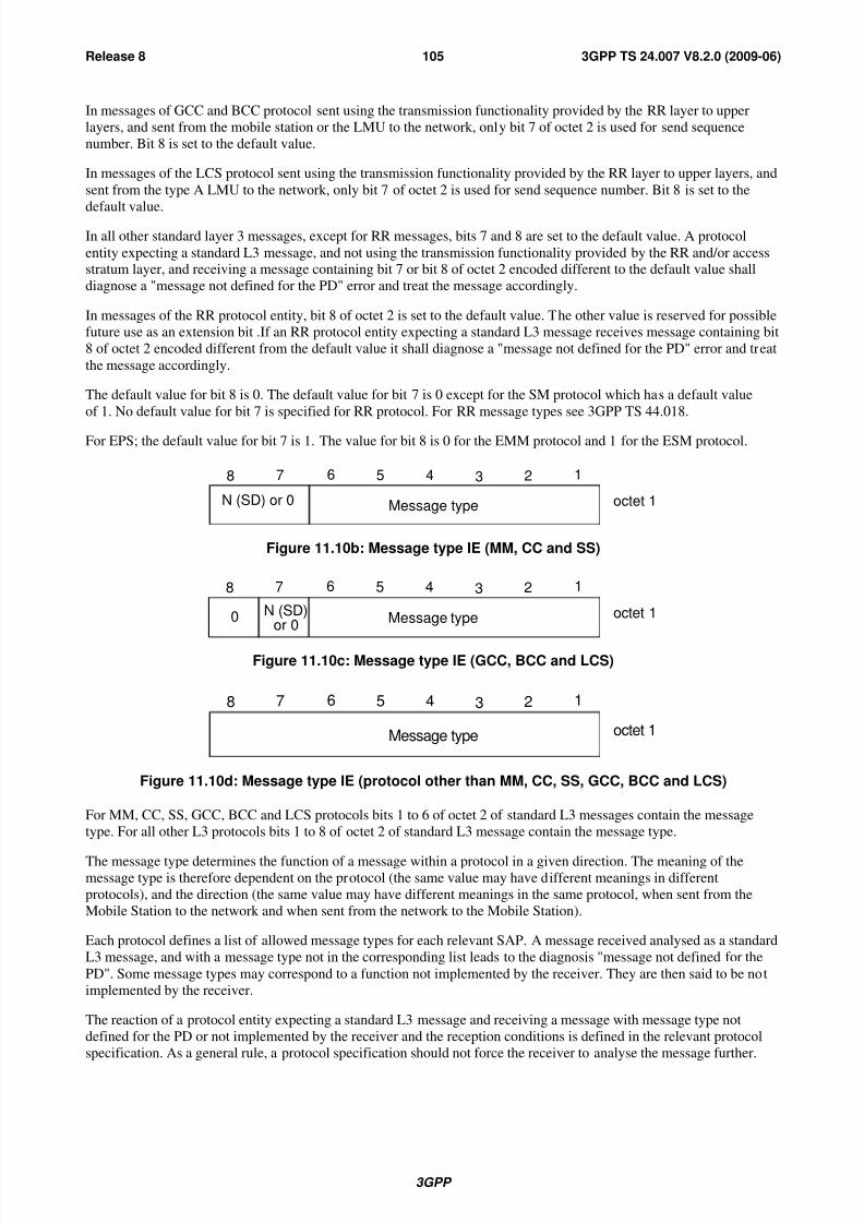
8/3/2019 3GPP TS 24007-V8.2.0
http://slidepdf.com/reader/full/3gpp-ts-24007-v820 105/149
3GPP
3GPP TS 24.007 V8.2.0 (2009-06)105Release 8
In messages of GCC and BCC protocol sent using the transmission functionality provided by the RR layer to upper
layers, and sent from the mobile station or the LMU to the network, only bit 7 of octet 2 is used for send sequence
number. Bit 8 is set to the default value.
In messages of the LCS protocol sent using the transmission functionality provided by the RR layer to upper layers, and
sent from the type A LMU to the network, only bit 7 of octet 2 is used for send sequence number. Bit 8 is set to the
default value.
In all other standard layer 3 messages, except for RR messages, bits 7 and 8 are set to the default value. A protocol
entity expecting a standard L3 message, and not using the transmission functionality provided by the RR and/or accessstratum layer, and receiving a message containing bit 7 or bit 8 of octet 2 encoded different to the default value shall
diagnose a "message not defined for the PD" error and treat the message accordingly.
In messages of the RR protocol entity, bit 8 of octet 2 is set to the default value. The other value is reserved for possible
future use as an extension bit .If an RR protocol entity expecting a standard L3 message receives message containing bit
8 of octet 2 encoded different from the default value it shall diagnose a "message not defined for the PD" error and treat
the message accordingly.
The default value for bit 8 is 0. The default value for bit 7 is 0 except for the SM protocol which has a default value
of 1. No default value for bit 7 is specified for RR protocol. For RR message types see 3GPP TS 44.018.
For EPS; the default value for bit 7 is 1. The value for bit 8 is 0 for the EMM protocol and 1 for the ESM protocol.
8 7 6 5 4 3 2 1
octet 1Message typeN (SD) or 0
Figure 11.10b: Message type IE (MM, CC and SS)
8 7 6 5 4 3 2 1
0 octet 1Message typeN (SD)
or 0
Figure 11.10c: Message type IE (GCC, BCC and LCS)
8 7 6 5 4 3 2 1
octet 1Message type
Figure 11.10d: Message type IE (protocol other than MM, CC, SS, GCC, BCC and LCS)
For MM, CC, SS, GCC, BCC and LCS protocols bits 1 to 6 of octet 2 of standard L3 messages contain the message
type. For all other L3 protocols bits 1 to 8 of octet 2 of standard L3 message contain the message type.
The message type determines the function of a message within a protocol in a given direction. The meaning of themessage type is therefore dependent on the protocol (the same value may have different meanings in different
protocols), and the direction (the same value may have different meanings in the same protocol, when sent from the
Mobile Station to the network and when sent from the network to the Mobile Station).
Each protocol defines a list of allowed message types for each relevant SAP. A message received analysed as a standard
L3 message, and with a message type not in the corresponding list leads to the diagnosis "message not defined for the
PD". Some message types may correspond to a function not implemented by the receiver. They are then said to be not
implemented by the receiver.
The reaction of a protocol entity expecting a standard L3 message and receiving a message with message type not
defined for the PD or not implemented by the receiver and the reception conditions is defined in the relevant protocol
specification. As a general rule, a protocol specification should not force the receiver to analyse the message further.
8/3/2019 3GPP TS 24007-V8.2.0
http://slidepdf.com/reader/full/3gpp-ts-24007-v820 106/149
3GPP
3GPP TS 24.007 V8.2.0 (2009-06)106Release 8
11.2.3.2.3 Sequenced message transfer operation
Upper layer messages sent using the RR sub-layer transport service from the mobile station to the network can be
duplicated by the data link layer in at least the following cases:
- in A/Gb mode, when a channel change of dedicated channels is required (assignment or handover procedure) and
the last layer 2 frame has not been acknowledged by the peer data link layer before the mobile station leaves the
old channel;
- in Iu mode, when an RLC re-establishment occurs (e.g. due to relocation) and the RLC layer has not
acknowledged the last one or more RLC PDUs before RLC re-establishment;
- an inter-system change from Iu mode to A/Gb mode is performed and the RLC layer has not acknowledged the
last one or more RLC PDUs;
- an inter-system change from A/Gb mode to Iu mode is performed and the last layer 2 frame in A/Gb mode has
not been acknowledged by the peer data link layer before the mobile station leaves the old channel.
In these cases, the mobile station does not know whether the network has received the messages correctly. Therefore,
the mobile station has to send the messages again when the channel change is completed.
The network must be able to detect the duplicated received messages. Therefore, each concerned upper layer messages
must be marked with a send sequence number.
To allow for different termination points in the infrastructure of the messages of different PDs, the sequence numberingis specific to each PD. For historical reasons, an exception is that messages sent with the CC, SS (via CS domain) and
MM PDs share the same sequence numbering. In the following, the phrase upper layer message flow refers to a flow
of messages sharing the same sequence numbering. The different upper layer flows are MM+CC+SS (via CS domain),
GCC, BCC and LCS. The GMM, EMM, SM, ESM, SMS, SS (via PS domain) and TC (Test Control, see
3GPP TS 44.014 [5a], 3GPP TS 34.109 [17a] and 3GPP TS 36.509 [26]) protocols do not use layer 3 sequence
numbering.
In a shared network with a MOCN configuration, Network Sharing non-supporting UEs can be redirected between CN
operators (see 3GPP TS 23.251 [22]). When the redirection takes place, the CN node of the redirecting CN operator
shall forward via the RAN the value of N(SD) of the last message received on the MM+CC+SS (via CS domain)message flow to the CN node of the next CN operator (3GPP TS 25.413 [23]).
11.2.3.2.3.1 Variables and sequence numbers
11.2.3.2.3.1.1 Send state variable V(SD)
The mobile station shall have one associated send state variable V(SD) ("Send Duplicated") for each upper layer
message flow. The send state variable denotes the sequence number of the next in sequence numbered message in the
flow to be transmitted. The value of the corresponding send state variable shall be incremented by one with each
numbered message transmission.
For the MM+CC+SS (via CS domain) upper layer message flow:
- when the RR connection starts with a core network of Release 98 or earlier, arithmetic operations on V(SD) are
performed modulo 2. The mobile station shall keep using modulo 2 for the duration of the RR connection;
- when the RR connection starts with a core network of Release 99 or later, arithmetic operations on V(SD) areperformed modulo 4. The mobile station shall keep using modulo 4 for the duration of the RR connection;
- after successful completion of SRVCC handover (see 3GPP TS 23.216 [27]), the mobile station shall perform
modulo 4 arithmetic operations on V(SD). The mobile station shall keep using modulo 4 until the release of the
RR connection established at SRVCC handover.
NOTE 1: In A/Gb mode, the release supported by the core network is indicated in the MSCR bit and in the SGSNR
bit in the system information broadcast (see 3GPP TS 44.018 [6b] and 3GPP TS 44.060 [10a]).
NOTE 2: During SRVCC handover the MSCR bit is not provided to the mobile station, and therefore the mobile
station assumes to access to a Release 99 or later core network.

8/3/2019 3GPP TS 24007-V8.2.0
http://slidepdf.com/reader/full/3gpp-ts-24007-v820 107/149
3GPP
3GPP TS 24.007 V8.2.0 (2009-06)107Release 8
For the GCC, BCC, and LCS upper layer message flows, arithmetic operations on V(SD) are performed modulo 2.
11.2.3.2.3.1.2 Send sequence number N(SD)
At the time when such a message to be numbered is designated for transmission, the value of N(SD) for the message to
be transferred is set equal to the value of the send state variable V(SD).
11.2.3.2.3.2 Procedures for the initiation, transfer execution and termination of the sequencedmessage transfer operation
11.2.3.2.3.2.1 Initiation
The sequenced message transfer operation is initiated by establishing a RR connection. The send state variables V(SD)
are set to 0.
After successful completion of SRVCC handover (see 3GPP TS 23.216 [27]), the mobile station shall set the send state
variable V(SD) to 0.
11.2.3.2.3.2.2 Transfer ExecutionThe core network shall compare the send sequence numbers of pairs of subsequent messages in the same upper layer
messages flow.
For the GCC, BCC, and LCS upper layer message flows, in case the send sequence numbers of two subsequent
messages in a flow are not identical, no duplication has occurred. In case the send sequence numbers are identical, the
network must ignore the second one of the received messages.
For the MM+CC+SS (via CS domain) upper layer message flow:
- when accessed by a release 98 or earlier mobile station, in case the send sequence numbers of two subsequent
messages in the flow are identical, the core network shall discard the second one of the received messages;
- when accessed by a release 99 or later mobile station, the core network shall discard any message whose N(SD)is not the increment by one (modulo 4) of the N(SD) of the last accepted message.
NOTE: The release supported by the mobile station is indicated by the revision level in the Mobile Station
Classmark 1 or Mobile Station Classmark 2 information element, or by the revision level indicator in the
MS network capability information element (see 3GPP TS 24.008, subclause 10.5).
In a shared network with a MOCN configuration, the core network node to which the mobile station was redirected
shall compare the send sequence number of the first message received after the redirection in the MM+CC+SS (via CS
domain) message flow with the value of N(SD) received during the redirection procedure (see 3GPP TS 23.251 [22]):
- when accessed by a release 98 or earlier mobile station, if the two send sequence numbers are identical, the core
network shall discard the received message from the mobile station;
- when accessed by a release 99 or later mobile station, the core network shall discard any message whose N(SD)is not the increment by one (modulo 4) of the N(SD) received during the redirection procedure.
11.2.3.2.3.2.3 Termination
The sequenced message transfer operation is terminated by the RR connection release procedure.
Inter system change from A/Gb mode to Iu mode or from Iu mode to A/Gb mode shall not terminate the sequenced
message transfer. UMTS SRNC relocation shall not terminate the sequenced message transfer.
11.2.3.3 Standard information elements of the imperative part
The message type octet of a standard L3 message may be followed by mandatory standard IEs having the format V, LV
or LV-E as specified in the message description in the relevant protocol specification.
As a design rule, octet boundaries must be respected. This implies that half-octet standard IEs (i.e., V formatted type 1
standard IEs) must appear by pair.
8/3/2019 3GPP TS 24007-V8.2.0
http://slidepdf.com/reader/full/3gpp-ts-24007-v820 108/149
3GPP
3GPP TS 24.007 V8.2.0 (2009-06)108Release 8
If message is received as a standard L3 message, and that is too short to contain the complete imperative part as
specified in the relevant protocol specification, an imperative message part error is diagnosed. (The same error may be
diagnosed at detection of certain contents of the imperative part of a message; this is defined in the relevant protocol
specification.) The treatment of an imperative message part error is defined in the relevant protocol specification.
11.2.4 Non-imperative part of a standard L3 message
The imperative part of a standard L3 message is followed by the (possibly empty) non-imperative part. The relevant
protocol specification defines where the imperative part of a standard L3 message ends. The non-imperative part of a
standard L3 message is composed of (zero, one, or several) standard IEs having the format T, TV, TLV or TLV-E. The
receiver of a standard L3 message shall analyse the non imperative part as a succession of standard IEs each containing
an IEI, and shall be prepared for the non-imperative part of the message to contain standard IEs that are not specified inthe relevant protocol specification.
An IEI may be known in a message or unknown in a message. Each protocol specification lists, for each message
(i.e., according to the message type, the direction and the lower layer SAP), the known standard IEs in the non-
imperative part.
An IEI that is known in a message designates the IE type of the IE the first part of which the IEI is, as well as the use of
the information. Which IE type it designates is specified in the relevant protocol specification. Within a message,different IEIs may designate the same IE type if that is defined in the relevant protocol specification.
Whether the second part of an IE with IEI known in a message is the length or not (in other words, whether the IEI is
the first part of an IE formatted as TLV, TLV-E or not) is specified in the relevant protocol specification.
Unless otherwise specified in the protocol specification, the receiver shall assume that IE with unknown IEI are TV
formatted type 1, T formatted type 2, TLV formatted type 4 or TLV-E formatted type 6 standard IEs. The IEI of
unknown IEs together with, when applicable, the length indicator, enable the receiver to determine the total length of
the IE, and then to skip unknown IEs. The receiver shall assume the following rule for IEs with unknown IEI:
Bit 8 of the IEI octet is set to "1" indicates a TV formatted type 1 standard IE or a T formatted type 2 IEs. Hence,
a 1 valued bit 8 indicates that the whole IE is one octet long.
Furthermore, for the EPS protocols EMM and ESM:
Bit 8 of the IEI octet set to "0" and bits 7 to 4 set to "1" indicates a TLV-E formatted type 6 IE, i.e. the followingtwo octets are length octets. Bit 8 of the IEI octet set to "0" and bit 7 to 4 set to any other bit combination
indicates a TLV formatted type 4 IE, i.e. the following octet is a length octet.
For all other protocols:
Bit 8 of the IEI octet set to "0" indicates a TLV formatted type 4 IE. Hence, the following octet is a length octet.
As a design rule, it is recommended that IEIs of any TV formatted type 1, T formatted type 2, TLV formatted type 4 or
TLV-E formatted type 6 IE follow the rule, even if assumed to be known by all potential receivers.
A message may contain two or more IEs with equal IEI. Two IEs with the same IEI in a same message must have the
same format, and, when of type 3, the same length. More generally, care should be taken not to introduce ambiguitiesby using an IEI for two purposes. Ambiguities appear in particular when two IEs potentially immediately successive
have the same IEI but different meanings and when both are non-mandatory. As a recommended design rule, messages
should contain a single IE of a given IEI.
Each protocol specification may put specific rules for the order of IEs in the non-imperative part. An IE known in the
message, but at a position non compliant with these rules is said to be out of sequence. An out of sequence IE is
decoded according to the format, and, when of type 3 the length, as defined in the message for its IEI.
11.2.5 Presence requirements of information elements
The relevant protocol specification may define three different presence requirements (M, C, or O) for a standard IE
within a given standard L3 message:
- M ("Mandatory") means that the IE shall be included by the sending side, and that the receiver diagnoses a
"missing mandatory IE" error when detecting that the IE is not present. An IE belonging to the imperative part of

8/3/2019 3GPP TS 24007-V8.2.0
http://slidepdf.com/reader/full/3gpp-ts-24007-v820 109/149
3GPP
3GPP TS 24.007 V8.2.0 (2009-06)109Release 8
a message has presence requirement M. An IE belonging to the non-imperative part of a message may have
presence requirement M;
- C ("Conditional") means:
* that inclusion of the IE by the sender depends on conditions specified in the relevant protocol specification;
* that there are conditions for the receiver to expect that the IE is present and/or conditions for the receiver toexpect that the IE is not present in a received message of a given PD, SAP and message type; these
conditions depend only on the content of the message itself, and not for instance on the state in which the
message was received, or on the receiver characteristics; they are known as static conditions;
* that the receiver detecting that the IE is not present when sufficient static conditions are fulfilled for its
presence, shall diagnose a "missing conditional IE" error;
* that the receiver detecting that the IE is present when sufficient static conditions are fulfilled for its non-
presence, shall diagnose an "unexpected conditional IE" error.
- Only IEs belonging to the non-imperative part of a message may have presence requirement C;
- O ("Optional") means that the receiver shall never diagnose a "missing mandatory IE" error, a "missing
conditional IE" error, or an "unexpected conditional IE" error because it detects that the IE is present or that theIE is not present. (There may however be conditions depending on the states, resources, etc. of the receiver to
diagnose other errors.) Only IEs belonging to the non-imperative part of a message may have presence
requirement O.
Unless otherwise specified the presence of a IE of unknown IEI or of an out of sequence IE shall not lead by itself to an
error. An alternative specification is the 'comprehension required' scheme. A type 4 IE is encoded as 'comprehension
required' if bits 5, 6, 7 and 8 of its IEI are set to zero. A type 6 IE is encoded as 'comprehension required' if bit 8 is set to
zero and bits 3, 4, 5, 6, and 7 of its IEI are set to one. The 'comprehension required' scheme is to be applied if explicitly
indicated in the protocol specification. The reaction on the reception of an unknown or out of sequence IE coded as
'comprehension required' is specified in the relevant protocol specification.
11.2.6 Description of standard L3 messagesThis subclause describes a generic description method for standard L3 messages, the tabular description. Protocol
specification may follow other methods.
A standard L3 message is described by a table listing the header elements and the standard IEs in the message. For each
element is given:
- if applicable the IEI, in hexadecimal representation (one digit followed by and hyphen for TV formatted type 1,
and two digits for the other cases);
- the name of the IE (this is used in particular for the description of conditional presence rules);
- the type of the information element, with a reference of where the internal structure of the value part is specified;
- the format of the standard IE (T, V, TV, LV, TLV, LV-E or TLV-E); and
- the length, or the range of lengths, of the whole standard IE, including when applicable the T and L parts.
The list of elements is given in the table in the order they appear in the resulting bit string, with the exception of
half-octet elements in the imperative part: half octets in a pair are inverted. This applies in particular for the two first
header elements: the protocol discriminator appears first in a table describing a standard L3 message.
11.3 Non standard L3 messages
In some protocols, the structure of part or all of the messages might not always follow the standard L3 message
structure. As a design rule, this should be consistent for a given protocol, direction and lower layer SAP.
A possibility is to describe the message with the compact notation described in Annex B.
A few consistent structures are found in the present protocol specifications, and are described hereafter.

8/3/2019 3GPP TS 24007-V8.2.0
http://slidepdf.com/reader/full/3gpp-ts-24007-v820 110/149
3GPP
3GPP TS 24.007 V8.2.0 (2009-06)110Release 8
Other structures can be described directly in the protocol specifications.
11.3.1 Case A: BCCH and AGCH/PCH messages
In these cases, the SAP capability is for fixed length messages. The messages are structured as standard L3 messages
plus one octet in front, the L2 pseudo length octet, and a rest octet part at the end.
11.3.1.1 L2 Pseudo Length octet
This octet, the L2 pseudo length indicator octet, indicates the length in octets of the subsequent octet string that can be
analysed as a standard L3 message.
The octet is structured as follows:
Bits 3 to 8 encodes in binary the L2 pseudo length, i.e., the length of the part to be analysed as a standard L3
message;
Bit 2 is set to "0";
Bit 1 is set to "1".
A receiver expecting a message so structured and receiving a message with bit 1 of octet 1 (i.e., the 8 th bit of the
message) set to "1" and bit 2 of octet 1 (i.e., the 7th
bit of the message) different from "0", shall abandon the analysis of
the message.
A receiver expecting a message so structured and receiving a message on AGCH/PCH:
- with an L2 pseudo length indicator encoding 0 or 1 shall skip the indicated number of octets and not try to analysethe standard L3 message part;
- with a L2 pseudo length indicator bigger than what is compatible with the SAP capability shall abandon the analysis
of the message.
11.3.1.2 Rest Octets
The part after the part structured as a standard L3 message, and up to the end of the message as constrained by lower
layers, is presented as a non standard IE of variable length (sometime indicated as of type 5), the "rest octets" IE.
The rest octets element may be described by table description, or, preferably, using the compact notation described in
Annex B of the present document.
11.3.1.3 Description of a modified standard L3 message
The description can be provided in the same way as a standard L3 message, with in the case of a tabular description one
non standard IE at the beginning (of type L2 pseudo length), and one non standard IE at the end.
11.3.2 Case B: SACCH / SDCCH / FACCH messages sent inunacknowledged mode
The messages are structured either as standard L3 messages, or in the so-called short header format. The value of the 8th
bit (bit 1 of octet 1) of the link layer PDU distinguishes the two cases. In the case of the short header, the L3 message is
the same bit string as the link layer PDU, and has a fixed length. The following description includes the 2-bit link layer
header.
11.3.2.1 The first octet
Bits 1 and 2 are the link layer header. Bit 2 of octet 1 is set to "0", and bit 1 is reserved for the link layer.
A protocol discriminator is the first part of the message (starting bit 8 of octet 1). The protocol discriminator field may
have different lengths. The following protocol discriminator is defined:
8/3/2019 3GPP TS 24007-V8.2.0
http://slidepdf.com/reader/full/3gpp-ts-24007-v820 111/149
3GPP
3GPP TS 24.007 V8.2.0 (2009-06)111Release 8
- 0 RR.
All additional PD defined for this structure shall start by 1. The reception of a message with bit 8 of octet 1 set to 1when expecting a message structured as defined by this clause shall be diagnosed as an unknown PD, and the message
ignored.
As a design rule, a message type field should follow the PD, and of a length such that the PD and the message type fit in
the 6 first bits of the message.
11.3.2.2 The rest of the message
The rest of the structure is not more constrained.
The preferred description method is the one described in Annex B.
11.3.3 Design guidelines for non standard parts
The guidelines in this subclause apply to non standard parts, such as rest octets, short header broadcast message or fully
non standard L3 messages.
11.3.3.1 General
The structure should be as far as possible be such that the analysis can be conducted from beginning to end. In other
terms, the conditions determining the syntactic analysis of a part (e.g., tags, lengths) should appear before that part.
The part should be structured as a succession of information elements, each carrying an elementary semantic
information. An information element should be composed of (possibly) a tag, than (possibly) a length indicator, then a
value part.
Tags can be of fixed or variable length, their extent being analysable from beginning to end. A typical tagging is the one
bit tagging, which should preferably used as follows: value "0" indicates that the IE is no more than the tag bit, and "1"
indicates that the IE continues at least with the next bit.
Variable length tagging should be used to distinguish between several possible formats of the element. Tag lengths are
then chosen according to packing efficiency criteria.
The T field of standard IEs can be presented as a variable tagging with only two lengths: 4 and 8 bits.
The length indicator can be of fixed or variable length, their extent being analysable from beginning to end. It should
preferably be presented as encoding the length in bits of the value part.
The L field of standard IEs can be presented as a fixed length (one octet) length indicator which can encode only
lengths multiple of 8 bits.
The value part can be described as further structured, in a similar way. This can be used to help the reading, and to
cover some presence dependence.
11.4 Handling of superfluous information
All equipment should be able to ignore any extra information present in an L3 message, which is not required for the
proper operation of that equipment. For example, a mobile station may ignore the calling party BCD number if that
number is of no interest to the Mobile Station when a SETUP message is received.
11.4.1 Information elements that are unnecessary in a message
The relevant protocol specification may define certain IEs to be under some conditions unnecessary in a L3 message. A
protocol entity detecting an unnecessary IE in a received L3 message shall ignore the contents of that IE for treating the
message; it is not obliged to check whether the contents of the IE are syntactically correct.

8/3/2019 3GPP TS 24007-V8.2.0
http://slidepdf.com/reader/full/3gpp-ts-24007-v820 112/149
3GPP
3GPP TS 24.007 V8.2.0 (2009-06)112Release 8
11.4.2 Other syntactic errors
This clause applies to the analysis of the value part of an information element. It defines the following terminology:
- An IE is defined to be syntactically incorrect in a message if it contains at least one value defined as "reserved",
or if its value part violates syntactic rules given in the specification of the value part.
- It is not a syntactical error that a type 4 and type 6 standard IE specifies in its length indicator a greater length
than possible according to the value part specification: extra bits shall be ignored.
- It should not be considered a syntactical error if a type 4 and type 6 IE is received with a shorter length than
defined in this version of the specification if the IE is correctly encoded according to an earlier version of the
specification.
- A message is defined to have semantically incorrect contents if it contains information which, possibly
dependant on the state of the receiver, is in contradiction to the resources of the receiver and/or to the procedural
part.

8/3/2019 3GPP TS 24007-V8.2.0
http://slidepdf.com/reader/full/3gpp-ts-24007-v820 113/149
3GPP
3GPP TS 24.007 V8.2.0 (2009-06)113Release 8
Annex A (informative):MN-Services arrow diagram
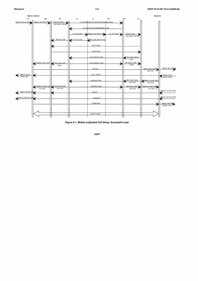
8/3/2019 3GPP TS 24007-V8.2.0
http://slidepdf.com/reader/full/3gpp-ts-24007-v820 114/149
3GPP
3GPP TS 24.007 V8.2.0 (2009-06)114Release 8
CC MM RR L2 L2 RR MM CC
Mobile Station Network
MNCC-SETUP-REQ DL-RANDOM-ACC-REQ/IND (CHANN REQ)
DL-UNIT-DATA-IND/REQ(IMM ASS)
DL-ASS-REQ DL-EST-IND
DL-EST-CNF UA (CM SERV REQ)
AUTH REQ
AUTH RES
CIPH MODE CMD
CIPH MODE COM
SETUP
CALL PROC
ASSIGN CMD
ASSIGN COM
ALERT
CONNECT
CONN ACK
MNCC-CALL-
PROC-IND
MNCC-ALERT-IND
MNCC-SETUP-CNF
MMCC-EST-CNF
MMCC-SYNC-IND
(res ass)
RR-EST-CNF
RR-SYNK-IND
(res ass)
RR-EST-IND
(CM SERV REQ)
RR-SYNC-REQ
(ciph)
RR-SYNC-CNF
(ciph)
RR-SYNC-REQ
(res ass)
RR-SYNC-CNF
(res ass)
MMCC-EST-IND
(SETUP)
MMCC-SYNC-REQ
(res ass)
MMCC-SYNC-CNF
(res ass)
MNCC-SETUP-IND
MNCC-CALL-
PROC-REQ
MNCC-ALERT-REQ
MNCC-SETUP-RSP
MNCC-SETUP-
COMPL-IND
DATA FLOW
MMCC-ES T-RE Q RR-EST-REQ
(CM SERV REQ)
RR-SYNC-IND
(ciph)
SABM (CM SERV REQ)
Figure A.1: Mobile originated Call Setup. Successful case
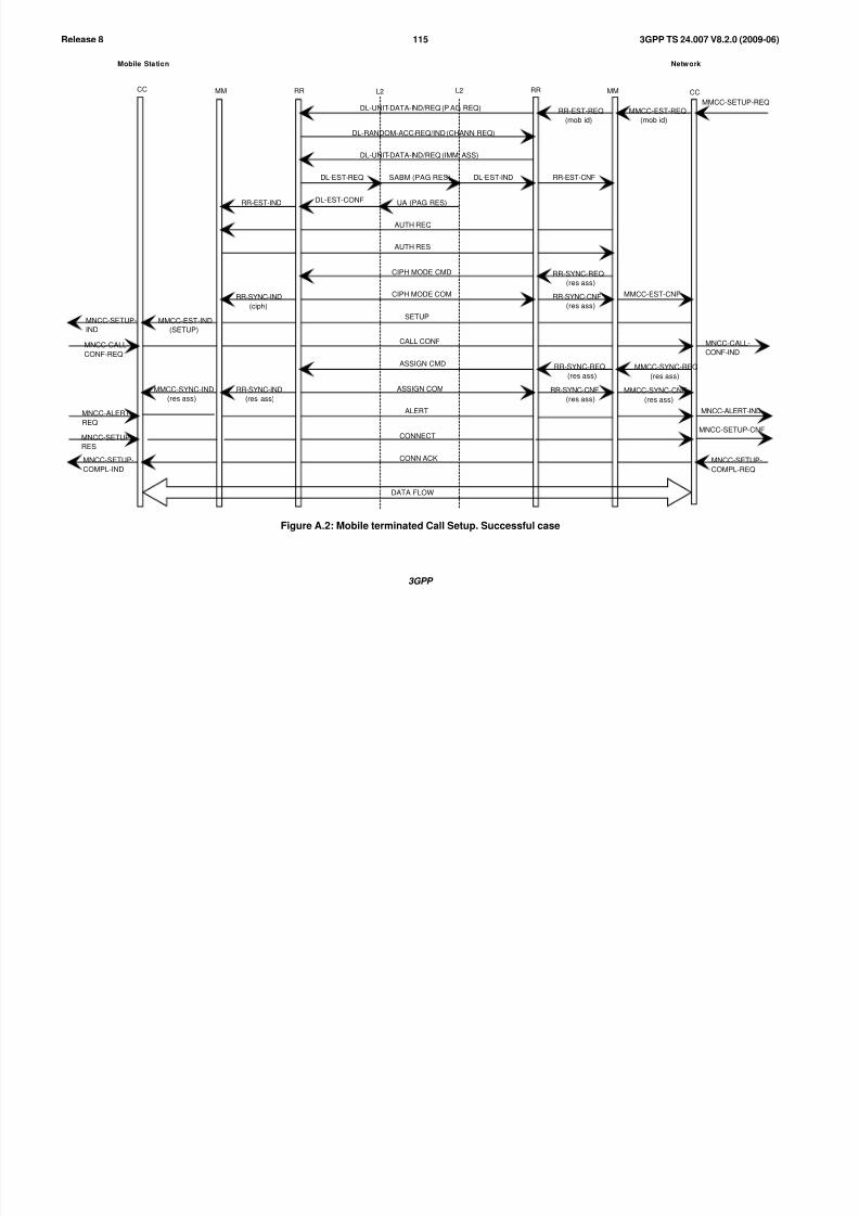
8/3/2019 3GPP TS 24007-V8.2.0
http://slidepdf.com/reader/full/3gpp-ts-24007-v820 115/149
3GPP
3GPP TS 24.007 V8.2.0 (2009-06)115Release 8
Mobile Station Network
DATA FLOW
DL-RANDOM-ACC-REQ/IND (CHANN REQ)
DL-UNIT-DATA-IND/REQ (IMM ASS)
DL-EST-REQ DL-EST-IND
DL-EST-CONF UA (PAG RES)
AUTH REQ
AUTH RES
CIPH MODE CMD
CIPH MODE COM
SETUP
CALL CONF
ASSIGN CMD
ASSIGN COM
ALERT
CONNECT
CONN ACK
RR-EST-IND
RR-SYNC-IND
(ciph)
RR-SYNC-IND
(res ass)
MMCC-EST-IND
(SETUP)
MMCC-SYNC-IND
(res ass)
MNCC-SETUP-
IND
MNCC-CALL-
CONF-REQ
MNCC-ALERT-
REQ
MNCC-SETUP-
RES
MNCC-SETUP-
COMPL-IND
RR-EST-REQ
(mob id)
RR-EST-CNF
RR-SYNC-REQ
(res ass)
RR-SYNC-CNF
(res ass)
RR-SYNC-REQ
(res ass)
RR-SYNC-CNF
(res ass)
MMCC-EST-REQ
(mob id)
MMCC-SETUP-REQ
MMCC-EST-CNF
MNCC-CALL-
CONF-IND
MMCC-SYNC-REQ
(res ass)
MMCC-SYNC-CNF
(res ass)
MNCC-ALERT-IND
MNCC-SETUP-CNF
MNCC-SETUP-
COMPL-REQ
SABM (PAG RES)
DL-UNIT-DATA-IND/REQ (P AG REQ)
MMCC RR L2 L2 RR MM CC
Figure A.2: Mobile terminated Call Setup. Successful case

8/3/2019 3GPP TS 24007-V8.2.0
http://slidepdf.com/reader/full/3gpp-ts-24007-v820 116/149
3GPP
3GPP TS 24.007 V8.2.0 (2009-06)116Release 8
Mobile Station Network
DATA FLOW
MNCC-DISC-REQ
MNCC-REL-IND
MMCC-REL-REQ
RR-REL-IND
DISCONNECT
RELEASE
RELEASE COM
CHANN REL
DL-REL-REQ
DL-REL-CNF
DISC
UA
DL-REL-IND
RR-REL-REQ MMCC-REL-REQ
MNCC-DISC-IND
MNCC-REL-REQ
MNCC-REL-CNF
CC RRL2 CCMM MMRR L2
Figure A.3: Mobile originated, Call Release and Channel Release. Successful case
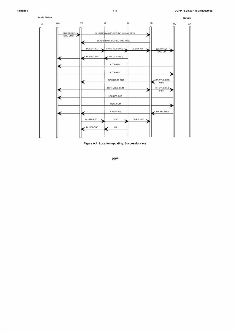
8/3/2019 3GPP TS 24007-V8.2.0
http://slidepdf.com/reader/full/3gpp-ts-24007-v820 117/149
3GPP
3GPP TS 24.007 V8.2.0 (2009-06)117Release 8
Mobile Station Network
RR-EST-REQ
(LOC UPD)
DL-RANDOM-ACC-REQ/IND (CHANN REQ)
DL-UNIT-DATA-IND/REQ (IMM A SS)
DL-EST-REQ SAHM (LOC UPD) DL-EST-IND
DL-EST-CNF UA (LOC UPD)
AUTH REQ
AUTH RES
CIPH MODE CMD
CIPH MODE COM
LOC UPD ACC
REAL COM
CHANN REL
DISC
UA
DL-REL-REQ
DL-REL-CNF
DL-REL-IND
RR-EST-IND
(LOC UP)
RR-SYNC-REQ
(ciph)
RR-SYNC-CNF
(ciph)
RR-REL-REQ
CC MM RR L2CCMMRRL2
Figure A.4: Location updating. Successful case

8/3/2019 3GPP TS 24007-V8.2.0
http://slidepdf.com/reader/full/3gpp-ts-24007-v820 118/149
3GPP
3GPP TS 24.007 V8.2.0 (2009-06)118Release 8
Mobile Station Network
DATA FLOW
DATA FLOW
HANDO CMD
DL-SUS-REQ (local)
DL-REL-CNF (local)
PHYS INFO
DL-RES-REQ
DL-EST-CNF
SAHM
UA
HANDO COM
DL-EST-IND
BS1
BS2
CC MM RR L2 CCMMRRL2
Figure A.5: Handover. Successful case

8/3/2019 3GPP TS 24007-V8.2.0
http://slidepdf.com/reader/full/3gpp-ts-24007-v820 119/149
3GPP
3GPP TS 24.007 V8.2.0 (2009-06)119Release 8
Mobile Station Network
MNX-SPECIFIC-REQ
(1MSG (X))
MMX-ES T-REQ RR-ES T-REQ
(CM SERV REQ)
RR-EST-CNF
MMX-EST-CNF RR-SYNC-IND
(ciph)
MMX-DATA-REQ
(1MSG (X))
MMX-DATA-DND
(2MSG (X))
RR-DATA-RE1
(1 MSG (X))
RR-DATA-DND
(2MSG (X))
MMX-SYNC-IND
(res ass)
MMX-DATA-REQ
(MSG (X))
MMY-EST-REQ
MMY-EST-CNF
MMY-DATA-REQ
(1 MSG (Y))
RR-SYNC-IND
(res ass)
RR-DATA-REQ
(MSG (X))
RR-DATA-REQ
(1MSG (Y))
CHANN REQ
IMM ASS
DL-EST-CNF
UA (CM SERV REQ)
AUTH REQ
AUTH RES
CIPH MODE CMD
CIPH MODE COM
1 MESSAGE (X)
2 MESSAGE (X)
ASSIGN CMD
ASSIGN COM
MESSAGE (X)
MESSAGE OF TRANSACTION X
OM SERV REQ
(serv 1)
OM SERV ACC
(serv 2)
1 MESSAGE (Y)
MESSAGE OF TRANSACTION X & Y
RR-EST-IND
(CM SERV REQ)
NR-SYNC-REQ
(ciph)
RR-SYNC-CNF
(ciph)
RR-DATA-IND
(1 MSG (X))
RR-DATA-REQ
2 MSG (X))
RR-SYNC-REQ
(res ass)
RR-SYNC-CNF
(res ass)
RR-DATA-IND
(MSG (X))
MMX-DATA-REQ
2 MSG (X))
MMX-SYNC-REQ
(res ass)
MMX-SYNC-CNF
(res ass)
MMX-DATA-IND
(MSG (X))
MMXX-EST IND
(1 MSG (X))
RR-DATA-IND
(1MSG (Y))
MMY-EST-IND
(1MSG (Y))
Transaction
Y
started
Transaction
X
started
IM-EST-REQ
(CM SERV REQ)IM-EST-IND
(CM SERV REQ)
SABM (CM SERV REL)
MMY-SPECIFIC-REQ
(1MSG (Y))
CM MM RR L2 CMMMRRL2
Figure A.6: Establishment of parallel transactions (General view)

8/3/2019 3GPP TS 24007-V8.2.0
http://slidepdf.com/reader/full/3gpp-ts-24007-v820 120/149
3GPP
3GPP TS 24.007 V8.2.0 (2009-06)120Release 8
Mobile Station Network
MMX-REL-REQ
MMY-REL-REQ
RR-REL-IND
Last message of specific Protocol (x)
MESSAGE OF TRANSACTIONS X & Y
MESSAGE OF TRANSACTIONS Y
Last message of specific Protocol (y)
CHANN REL
DL-REL-REQ
DL-REL-CNF
DISC
UA
DL-REL-IND
MMX-REL-REQ
MMY-REL-REQ
Transactionreleased
Transactionreleased
Channelreleased
CM MM RR L2 CMMMRRL2
Figure A.7: Release of parallel transactions (General view)

8/3/2019 3GPP TS 24007-V8.2.0
http://slidepdf.com/reader/full/3gpp-ts-24007-v820 121/149
3GPP
3GPP TS 24.007 V8.2.0 (2009-06)121Release 8
Annex B (informative):Description of CSN.1
The goal of the notation described hereafter is to describe the structure of the syntactically correct messages for a givensignalling protocol, or of part of such messages. The notation addresses the cases where the concrete messages are
binary strings. The notation allows to describe sets of strings: the structure of a message defined a protocol defines a set
of allowable bit strings. It also allows to put labels on parts of strings that follow a given structure.
One aspect of the specification of message set is to define the set of strings that are acceptable as when received. All thestrings that cannot be recognized as syntactically correct messages are to be rejected for syntactical reasons. In many
cases, only a subset of this set are allowed to be sent. The notation allows also to distinguish the set of the strings that
can be sent and the set of strings that are recognized as syntactically correct.
Another aspect of the specification of messages is the splitting of an acceptable string in a number of sub-strings that
will be use to derive the exact significance of the message. The notation provides this function by labelling sub-strings.
These labels can then in turn be used in textual or formal semantic descriptions which are not covered in the presentdocument.
The notation described here could be enhanced in the future, with the addition of new rules.
B.1 The Basic Rules
The following rules (B1 to B6) form the core part of the notation, more or less directly inherited from BNF. Rules B7 to
B8 add what is needed in addition to encode the rest octet parts of fixed length messages as defined in
3GPP TS 24.008 [6].
Rule A1 is not needed to describe sets of strings at this stage. It is the one allowing to label parts of messages.
B.1.1 Core Rules
B.1.1.1 Rule B1: Bits
A "bit string" is an ordered sequence of symbols, each belonging to a two-value set.
The character "0" and "1" are used to indicate one bit, respectively of one or the other value.
Formally, the notations « 0 » and « 1 » denote each a set composed of a single bit string of a single bit, of different
values.
In addition the word "bit" denotes the set of the two 1-bit long strings, namely 0 and 1.
B.1.1.2 Rule B2: Null String
Where needed, the word "null" call be used to indicate the null string, i.e., the string of no symbols.
Formally, the notation « null » denote the set composed of a single bit string, the empty string.
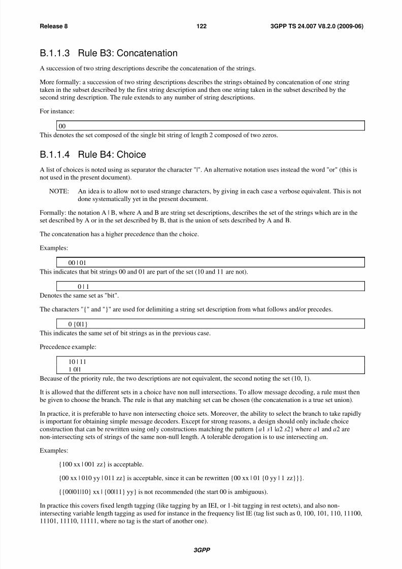
8/3/2019 3GPP TS 24007-V8.2.0
http://slidepdf.com/reader/full/3gpp-ts-24007-v820 122/149
3GPP
3GPP TS 24.007 V8.2.0 (2009-06)122Release 8
B.1.1.3 Rule B3: Concatenation
A succession of two string descriptions describe the concatenation of the strings.
More formally: a succession of two string descriptions describes the strings obtained by concatenation of one string
taken in the subset described by the first string description and then one string taken in the subset described by the
second string description. The rule extends to any number of string descriptions.
For instance:
00
This denotes the set composed of the single bit string of length 2 composed of two zeros.
B.1.1.4 Rule B4: Choice
A list of choices is noted using as separator the character "|". An alternative notation uses instead the word "or" (this is
not used in the present document).
NOTE: An idea is to allow not to used strange characters, by giving in each case a verbose equivalent. This is not
done systematically yet in the present document.
Formally: the notation A | B, where A and B are string set descriptions, describes the set of the strings which are in the
set described by A or in the set described by B, that is the union of sets described by A and B.
The concatenation has a higher precedence than the choice.
Examples:
00 | 01
This indicates that bit strings 00 and 01 are part of the set (10 and 11 are not).
0 | 1
Denotes the same set as "bit".
The characters "{" and "}" are used for delimiting a string set description from what follows and/or precedes.
0 {0|1}
This indicates the same set of bit strings as in the previous case.
Precedence example:
10 | 11
1 0|1
Because of the priority rule, the two descriptions are not equivalent, the second noting the set (10, 1).
It is allowed that the different sets in a choice have non null intersections. To allow message decoding, a rule must then
be given to choose the branch. The rule is that any matching set can be chosen (the concatenation is a true set union).
In practice, it is preferable to have non intersecting choice sets. Moreover, the ability to select the branch to take rapidly
is important for obtaining simple message decoders. Except for strong reasons, a design should only include choice
construction that can be rewritten using only constructions matching the pattern {a1 s1 |a2 s2} where a1 and a2 are
non-intersecting sets of strings of the same non-null length. A tolerable derogation is to use intersecting an.
Examples:
{100 xx | 001 zz} is acceptable.
{00 xx | 010 yy | 011 zz} is acceptable, since it can be rewritten {00 xx | 01 {0 yy | 1 zz}}}.
{{00|01|10} xx | {00|11} yy} is not recommended (the start 00 is ambiguous).
In practice this covers fixed length tagging (like tagging by an IEI, or 1-bit tagging in rest octets), and also non-
intersecting variable length tagging as used for instance in the frequency list IE (tag list such as 0, 100, 101, 110, 11100,11101, 11110, 11111, where no tag is the start of another one).
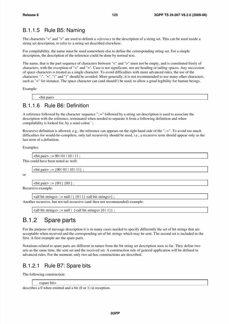
8/3/2019 3GPP TS 24007-V8.2.0
http://slidepdf.com/reader/full/3gpp-ts-24007-v820 123/149
3GPP
3GPP TS 24.007 V8.2.0 (2009-06)123Release 8
B.1.1.5 Rule B5: Naming
The characters "<" and ">" are used to delimit a reference to the description of a string set. This can be used inside a
string set description, to refer to a string set described elsewhere.
For compilability, the name must be used somewhere else to define the corresponding string set. For a simple
description, the description of the reference could be done by normal text.
The name, that is the part sequence of characters between "<" and ">" must not be empty, and is constituted freely of
characters, with the exception of "<" and ">". Case is not significant, nor are heading or tailing spaces. Any succession
of space characters is treated as a single character. To avoid difficulties with more advanced rules, the use of the
characters ":", "=", "(" and ")" should be avoided. More generally, it is not recommended to use many other characters,
such as "<" for instance. The space character can (and should!) be used, to allow a good legibility for human beings.
Example:
<bit pair>
B.1.1.6 Rule B6: Definition
A reference followed by the character sequence "::=" followed by a string set description is used to associate thedescription with the reference, terminated when needed to separate it from a following definition and when
compilability is looked for, by a semi-colon ' ;.
Recursive definition is allowed, e.g., the reference can appears on the right hand side of the "::=". To avoid too much
difficulties for would-be-compilers, only tail recursivity should be used, i.e., a recursive term should appear only as the
last term of a definition.
Examples:
<bit pair> ::= 00 | 01 | 10 | 11 ;
This could have been noted as well:
<bit pair> ::= {00 | 01 | 10 | 11} ;or
<bit pair> ::= {0|1} {0|1} ;
Recursive example:
<all bit strings> ::= null | { {0 | 1} <all bit strings>} ;
Another recursive, but not tail-recursive (and then not recommended) example:
<all bit strings> ::= null | {<all bit strings> {0 | 1}} ;
B.1.2 Spare parts
For the purpose of message description it is in many cases needed to specify differently the set of bit strings that are
acceptable when received and the corresponding set of bit strings which may be sent. The second set is included in thefirst. A first example are the spare parts.
Notations related to spare parts are different in nature from the bit string set description seen so far. They define two
sets as the same time, the sent set and the received set. A construction rule of general application will be defined in
advanced rules. For the moment, only two ad-hoc constructions are described.
B.1.2.1 Rule B7: Spare bits
The following construction:
<spare bit>describes a 0 when emitted and a bit (0 or 1) in reception.

8/3/2019 3GPP TS 24007-V8.2.0
http://slidepdf.com/reader/full/3gpp-ts-24007-v820 124/149
3GPP
3GPP TS 24.007 V8.2.0 (2009-06)124Release 8
B.1.2.2 Rule B8: Padding bits
An issue specific to the GSM radio interface protocols is that in some cases the messages cannot take arbitrary lengths.
Padding is then necessary to fill up the message up to the desired length. Moreover, the padding uses a particular
sequence of bits, of fixed position, i.e., the value of a padding bit depends on its position relative to the start of themessage. The padding sequence is protocol-specific. In most cases it is constituted of all 0 values, in which case the
following notation is of no use. In the case of GSM 04.08, the padding sequence is the repetition of octet 00101011,starting on an octet boundary.
The special notations "L" and "H" are used to denote the respectively the bit value corresponding to the padding spare
bit for that position, and the other value.
The notations "0", "1", "null", "L" and "H" are the only terminals in CSN.1.
Padding spare bits are bits which are set to the indicated value in emission whereas in reception any bit string is
acceptable. The following notation:
<spare L>
describes a bit which has a logical value L in emission, and is a bit (0 or 1) in reception.
The term <spare padding> denotes the required padding spare bits needed to fill up the message. The construction canbe developed only partially from the rules described so far, because the length limitation does not appear in the
following description:
< spare padding> ::= <spare L> {null | < spare padding>};
B.1.3 Predefined sets
The notation allows a modular description of the messages. This means in particular the possibility to build a library of bit string set definitions to be used wherever needed. The following is an example of an elementary library, which could
be specified once and can be used in other specifications without being redefined.
<bit> ::= 0|1 ;
<bit (1)> ::= <bit>;<bit (2)> ::= <bit> <bit>;
<bit (3)> ::= <bit (2)> <bit>;
<bit (4)> ::= <bit (3)> <bit>;
<bit (5)> ::= <bit (4)> <bit>;
<bit (6)> ::= <bit (5)> <bit>;
<bit (7)> ::= <bit (6)> <bit>;
<octet> ::= <bit (7)> <bit>;
<half octet> ::= <bit (4)>;
<spare half octet> ::= <spare bit><spare bit><spare bit><spare bit>;
<spare padding> ::= <spare L> {null | <spare padding>};
<octet string(i)> ::= <octet>
(i)
; -- for any positive or null integer i<bit(i)> ::= <bit>(i); -- for any positive or null integer I
<bit string> ::= bit**;
<octet string> ::= <octet>**;
NOTE 1: The definition of generic constructions such as <bit string(i)> is somewhat cumbersome with only the basicrules. More advanced rules would allow a much more compact notation.
NOTE 2: The use of the characters "(" and ")" within a reference is done consistently with potential advanced rules.NOTE 3: This basic library is not exhaustive and can be extended when the needs arise.

8/3/2019 3GPP TS 24007-V8.2.0
http://slidepdf.com/reader/full/3gpp-ts-24007-v820 125/149
3GPP
3GPP TS 24.007 V8.2.0 (2009-06)125Release 8
B.1.4 Labelling Parts
B.1.4.1 Rule A1: Labels
Delimited names as defined by Rule B6 identify sets of sub strings. In many cases this can be used within the context of
a message to refer to the specific part of the message. However, this is not of general application, since it may happenthat two parts of a message follow the same structure, and economy of notation requires that the structure is described
but once.
The general syntax that follows allows to refer to a part inside a description:
<name1 : string description>
For the definition of string sets, this is equivalent to the string description being used alone.
The name used as a label can be built according to the rules applicable to parenthesed references.
Examples:
<Tag : 000 ><Field : <Field type>>
<Field : octet>
The third example shows the use of a non parentheses reference to obtain a more elegant expression than, for instance,
the second example. At this stage, labels has no use for describing message syntax, but can be used to refer to the
corresponding part of the string, e.g., in the description of the message specifying the relationship between the
syntactical content and the semantical contents of the message, or to associate properties with effective sub-strings ineffective messages (rather than with sets of sub strings). Syntactical use of the semantical identifier are presented in
more advanced rules.
The same name may appear in several places. Designers have to be careful to use non ambiguous names if non-ambiguous reference is desired.
B.1.5 Goodies
B.1.5.1 Rule G1: Comments
Comments can be added, starting with the term "--" and ended by the end of line. Comments can be used in particular to
indicate the section where a particular description can be found.
B.2 Advanced rules
B.2.1 Rule A2: Exponent notation
An arithmetic expression used as exponent after a delimited string description is used to indicate repetitions.
A numerical expression between parentheses indicates a fixed number of repetitions.
<octet> ::= {0 | 1}(8) ;
is equivalent to
<octet> ::= {0 | 1} {0 | 1} {0 | 1} {0 | 1} {0 | 1} {0 | 1} {0 | 1} {0 | 1} ;
This could also be written:
<octet> ::= bit(8) ;
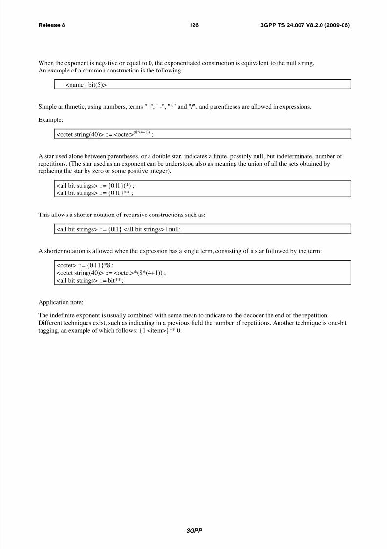
8/3/2019 3GPP TS 24007-V8.2.0
http://slidepdf.com/reader/full/3gpp-ts-24007-v820 126/149
3GPP
3GPP TS 24.007 V8.2.0 (2009-06)126Release 8
When the exponent is negative or equal to 0, the exponentiated construction is equivalent to the null string.An example of a common construction is the following:
<name : bit(5)>
Simple arithmetic, using numbers, terms "+", " -", "*" and "/", and parentheses are allowed in expressions.
Example:
<octet string(40)> ::= <octet>(8*(4+1)) ;
A star used alone between parentheses, or a double star, indicates a finite, possibly null, but indeterminate, number of repetitions. (The star used as an exponent can be understood also as meaning the union of all the sets obtained by
replacing the star by zero or some positive integer).
<all bit strings> ::= {0 |1}(*) ;
<all bit strings> ::= {0 |1}** ;
This allows a shorter notation of recursive constructions such as:
<all bit strings> ::= {0|1} <all bit strings> | null;
A shorter notation is allowed when the expression has a single term, consisting of a star followed by the term:
<octet> ::= {0 | 1}*8 ;
<octet string(40)> ::= <octet>*(8*(4+1)) ;
<all bit strings> ::= bit**;
Application note:
The indefinite exponent is usually combined with some mean to indicate to the decoder the end of the repetition.
Different techniques exist, such as indicating in a previous field the number of repetitions. Another technique is one-bit
tagging, an example of which follows: {1 <item>}** 0.

8/3/2019 3GPP TS 24007-V8.2.0
http://slidepdf.com/reader/full/3gpp-ts-24007-v820 127/149
3GPP
3GPP TS 24.007 V8.2.0 (2009-06)127Release 8
Annex C (informative):GPRS-Services sequence diagram
Instead of providing a complete set of all scenarios, the intention of this clause is to provide some typical examples. Itshall be noted, that within the figures only those parameters of the PDUs and the service primitives are shown, which
are needed for a general understanding of the examples. Furthermore during the examples below (except C.17) no cell
re-selection takes place.
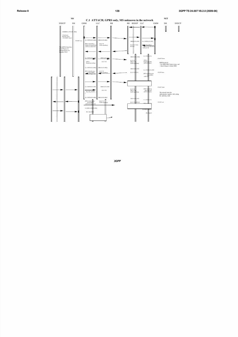
8/3/2019 3GPP TS 24007-V8.2.0
http://slidepdf.com/reader/full/3gpp-ts-24007-v820 128/149
3GPP
3GPP TS 24.007 V8.2.0 (2009-06)128Release 8
C.1 ATTACH, GPRS only, MS unknown in the network
GMMREG-ATTACH- REQ
[Attach type,
READY-timer,
STANDBY-timer ]
START TattachLL-UNITDATA-REQ
[PDU=Attach Req (
IMSI or TLLIplusRAI),
oldTLLI,Cipher=off ]
GRR-DATA-REQ
[LLC-UI,
SAPI=signalling]
GRR-DATA-IND
[LLC-UI, TLLI,
RAI,CI]
LL-UNITDATA-IND
[PDU=Attach Req (
IMSI or TLLIplusRAI),
oldTLLI, CI]
LLGMM-ASSIGN-REQ
[Kc, Algorithm]
START Tauth
LL-UNITDATA-REQGRR-DATA--REQ
STOP Tauth
[ PDU=Auth-Cipher-
Req (Alg, RAND,..),
oldTLLI, Cipher=off ]
[LLC-UI,
DRX, CLM,
SAPI=signalling]
GRR-DATA-IND
[LLC-UI]
LL-UNITDATA-IND
[PDU=Auth-Cipher-
Req (Alg., RAND,…)
]
LL-UNITDATA-REQ
[PDU=Auth-Cipher-
Resp (SRES),
oldTLLI,Cipher=off ]
GRR-DATA-REQ
[LLC-UI,
SAPI=signalling]
GRR-DATA-IND
[LLC-UI, oldTLLI]
LL-UNITDATA-IND
[PDU=Auth-Cipher-
Resp (SRES),
oldTLLI ]
[Kc, Algorithm]
MS NET
GMMSNDCP LLC RR SM SNDCPLLCRR BSSGPSM GMM
LLGMM-ASSIGN-REQ
START Tident
LL-UNITDATA-REQ
[ PDU=
Identification Req,
oldTLLI, Cipher=off ]
GRR-DATA--REQ
[LLC-UI,
DRX, CLM,
SAPI=signalling]
GRR-DATA-IND
[LLC-UI]
LL-UNITDATA-IND
[PDU=
Identification Req]
STOP Tident
LL-UNITDATA-REQ
[PDU=Identification-
Resp (IMSI),
oldTLLI,Cipher=off ]
GRR-DATA-REQ
[LLC-UI,
SAPI=signalling]
GRR-DATA-IND
[LLC-UI, TLLI]
LL-UNITDATA-IND
[PDU=Identification-
Resp (IMSI),
oldTLLI ]
The oldTLLI may be a
Local TLLI, or a
Foreign TLLI, or a
Random TLLI
IMSI fetched if
- No GPRS MM Context exists, and
- Attach Request without IMSI
The network starts the
authentication together with setting
the ciphering mode.
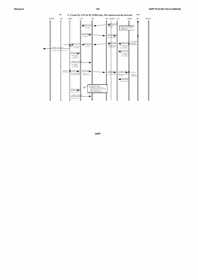
8/3/2019 3GPP TS 24007-V8.2.0
http://slidepdf.com/reader/full/3gpp-ts-24007-v820 129/149
3GPP
3GPP TS 24.007 V8.2.0 (2009-06)129Release 8
MS NET
GMMSNDCP LLC RR SM SNDCPLLCRR BSSGPSM GMM
C.1 (cont’d): ATTACH, GPRS only, MS unknown in the network
START TAttachSTOP Tattach
GMMREG-ATTACH- CNF
[ PLMN’s MT caps, Attach- type]
STOP Tattach
LL-UNITDATA-REQ
[PDU=Attach Accept(
newTLLI),
oldTLLI,Cipher=on ]
GRR-DATA--REQ
[LLC-UI, oldTLLI,
SAPI=signalling ]
GRR-DATA-IND
[LLC-UI ]
LL-UNITDATA-IND
[PDU=Attach Accept(
newTLLI) ]
LLGMM-ASSIGN-REQ
[Rx: oldTLLI or
newTLLI
TX: new TLLI ]
LLGMM-ASSIGN-REQ
[Rx: oldTLLI or
newTLLI
TX: new TLLI ]
LL-UNITDATA-REQ
[PDU=Attach complete,
newTLLI,Cipher=on ]
GRR-DATA-REQ
[LLC-UI,
SAPI=signalling ]
GRR-DATA-IND
[LLC-UI, newTLLI ]
LL-UNITDATA-IND
[PDU=Attach Complete,
newTLLI]
[ unassign oldTLLI ]
LLGMM-ASSIGN-REQ
GMMRR-ASSIGN-REQ
[Rx: oldTLLI or
newTLLI
TX: new TLLI ]]
RESTART
READY-timer
RESTART
READY-timer
LLGMM-ASSIGN-REQ
[ unassign oldTLLI ]
GMMRR-ASSIGN-REQ
[ unassign oldTLLI ]
A new TLLI
is assigned
Implementation option:Unassignment of old TLLI e.g.
- with reception of first LLC frame
using th e new TLLI
- expiry of appropriate timer
GRR-INITDATA--REQ
[LLC-XID ]
GRR-UNITDATA-IND
[ LLC-XID, TLLI, CI ]
GRR-UNITDATA-IND
[ LLC-XID ]
GRR-UNITDATA-REQ
[ LLC-XID ]
Exchange of new INPUT
OFSET value
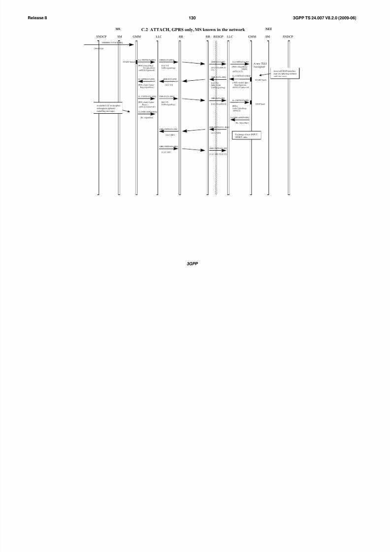
8/3/2019 3GPP TS 24007-V8.2.0
http://slidepdf.com/reader/full/3gpp-ts-24007-v820 130/149
3GPP
3GPP TS 24.007 V8.2.0 (2009-06)130Release 8
C.2 ATTACH, GPRS only, MS known in the network
GMMREG-ATTACH-REQ
[Attach type]
START TattachLL-UNITDATA-REQ GRR-DATA-REQ
[LLC-UI,
SAPI=signalling]
GRR-DATA-IND
[LLC-UI, oldTLLI
CI]
LL-UNITDATA-IND
[PDU=Attach Req (
CKSN),
oldTLLI, CI]
A new TLLI
is assigned
MS NET
GMMSNDCP LLC RR SM SNDCPLLCRR BSSGPSM GMM
[PDU=Attach Req (
TLLIplusRAI),
oldTLLI,Cipher=off ]
START Tauth
LL-UNITDATA-REQGRR-DATA--REQ
STOP Tauth
[ PDU=Auth-Cipher-
Req( Algoritm),
oldTLLI, Cipher=off ]
[LLC-UI,
DRX, CLM,
SAPI=signalling]
GRR-DATA-IND
[LLC-UI]
LL-UNITDATA-IND
[PDU=Auth-Cipher-
Req (Algorithm) ]
LL-UNITDATA-REQ
[PDU=Auth-Cipher-
Resp ( ),
oldTLLI,Cipher=off ]
GRR-DATA-REQ
[LLC-UI,
SAPI=signalling]
GRR-DATA-IND
[LLC-UI, oldTLLI]
LL-UNITDATA-IND
[PDU=
Auth-CipherResp,
oldTLLI ]LLGMM-ASSIGN-REQ
[ Kc, Algorithm ]
to enable LLC to decipher
subsequent ciphered
signalling messages
received CKSN matches,
start of ciphering without
authentication
[ Kc, Algorithm ]
LLGMM-ASSIGN-REQ
GRR-INITDATA--REQ
[LLC-XID ]
GRR-UNITDATA-IND
[ LLC-XID, TLLI, CI ]
GRR-UNITDATA-IND
[ LLC-XID ]
GRR-UNITDATA-REQ
[ LLC-XID ]
Exchange of new INPUT
OFSET value

8/3/2019 3GPP TS 24007-V8.2.0
http://slidepdf.com/reader/full/3gpp-ts-24007-v820 131/149
3GPP
3GPP TS 24.007 V8.2.0 (2009-06)131Release 8
C.2 (cont’d) ATTACH, GPRS only, MS known in the network
START TattachSTOP TattachGMMREG-ATTACH-
CNF
[ PLMN’s MT caps, Attach- type]
LL-UNITDATA-REQ
[PDU=Attach Accept(
newTLLI),
oldTLLI, Cipher=on ]
GRR-DATA-REQ
[LLC-UI,
SAPI=signalling ]
GRR-DATA-IND
[LLC-UI ]
LL-UNITDATA-IND
[PDU= Attach Accept(
new TLLI) ]
LLGMM-ASSIGN-REQLLGMM-ASSIGN-REQ
[Rx: oldTLLI or newTLLI
TX: new TLLI , Kc,
Algorithm ]
STOP Tattach
[ Rx: old or newTLLI
TX: new TLLI ] ]
LL-UNITDATA-REQ
[PDU=Attach complete,
newTLLI, Cipher=on ]
GRR-DATA-REQ
[LLC-UI,
SAPI=signalling ]
GRR-DATA-IND
[LLC-UI, newTLLI ]
LL-UNITDATA-IND
[PDU=Attach Complete,
newTLLI]
[ unassign oldTLI ]
LLGMM-ASSIGN-REQ
GMMRR-ASSIGN- REQ
RESTART
READY-timer
RESTART
READY-timer
MS NET
GMMSNDCP LLC RR SM SNDCPLLCRR BSSGPSM GMM
LLGMM-ASSIGN-REQ
[ unassign oldTLLI ]
GMMRR-ASSIGN-REQ
[ unassign oldTLLI ]
[Kc, Algorithm ]
[ Rx: old or newTLLI
TX: new TLLI ] ]
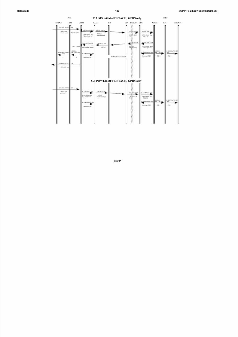
8/3/2019 3GPP TS 24007-V8.2.0
http://slidepdf.com/reader/full/3gpp-ts-24007-v820 132/149
3GPP
3GPP TS 24.007 V8.2.0 (2009-06)132Release 8
MS NET
GMMSNDCP LLC RR SM SNDCPLLCRR BSSGPSM GMM
C.3 MS initiated DETACH, GPRS only
GMMREG-DETACH- REQ
[Detach-type,
normal-detach ] START Tdetach
LL-UNITDATA-REQ
[PDU=Detach Req,
TLLI, Cipher=on ]
GRR-DATA-REQ
[LLC-UI,
SAPI=signalling]
GRR-DATA-IND
[LLC-UI, TLLI
CI]
LL-UNITDATA-IND
[PDU=Detach Req,
TLLI, CI]
STOP Tdetach
GMMREG-DETACH- CNF
[ Detach- type]
LL-UNITDATA-REQ
[PDU=Detach Accept
TLLI, Cipher=on ]
GRR-DATA--REQ
[LLC-UI,
SAPI=signalling]
GRR-DATA-IND
[LLC-UI]
LL-UNITDATA-IND
[PDU=Detach Accept]
LL-UNITDATA-REQ
[ PDU=Detach Req,
TLLI, Cipher=on ]
GRR-DATA-REQ
[ LLC-UI,
SAPI=signalling ]
GRR-DATA-IND
[ LLC-UI, TLLI
CI ]
LL-UNITDATA-IND
[PDU=Detach Req,
TLLI, CI]
C.4 POWER-OFF DETACH, GPRS only
LLGMM-ASSIGN-REQ
[ unassign TLLI] All LLC links are aborted
SNSM-DEACTIVATE
-IND
[ ]
GMMSM-
RELEASE -IND
[ ]
LLGMM-ASSIGN-REQ
[ unassign TLLI]
SNSM-DEACTIVATE
-IND
[ TLLI ]
GMMSM-
RELEASE-IND
[ TLLI ]
GMMREG-DETACH- REQ
[Detach-type,
power off ]
LLGMM-ASSIGN-REQ
[ unassign TLLI]
SNSM-DEACTIVATE
-IND
[ TLLI ]
GMMSM-
RELEASE-IND
[ TLLI ]
LLGMM-ASSIGN-REQ
[ unassign TLLI]
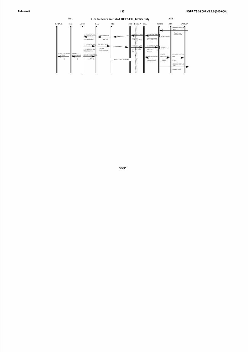
8/3/2019 3GPP TS 24007-V8.2.0
http://slidepdf.com/reader/full/3gpp-ts-24007-v820 133/149
3GPP
3GPP TS 24.007 V8.2.0 (2009-06)133Release 8
MS NET
GMMSNDCP LLC RR SM SNDCPLLCRR BSSGPSM GMM
C.5 Network initiated DETACH, GPRS only
GMMREG-DETACH-
REQ
[Detach-type,
normal-detach ]
LL-UNITDATA-REQ
[PDU=Detach Accept,
TLLI, Cipher=on ]
GRR-DATA-REQ
[LLC-UI,
SAPI=signalling]
GRR-DATA-IND
[LLC-UI, TLLI
CI]
LL-UNITDATA-IND
[PDU=Detach Accept,
TLLI, CI]
STOP Tdetach
GMMREG-DETACH-
CNF
[ Detach- type]
LL-UNITDATA-REQ
[PDU=Detach Req,
TLLI , Cipher=on]
GRR-DATA-REQ
[LLC-UI,
SAPI=signalling]
GRR-DATA-IND
[LLC-UI]
LL-UNITDATA-IND
[PDU=Detach Req]
LLGMM-ASSIGN-REQ
[ unassign TLLI]All LLC links are aborted
SNSM-DEACTIVATE
-IND
[ ]
GMMSM-
RELEASE -IND
[ ]
LLGMM-ASSIGN-REQ
[ unassign TLLI]
SNSM-DEACTIVATE
-IND
[ TLLI ]
GMMSM-
RELEASE-IND
[ TLLI ]
START Tdetach
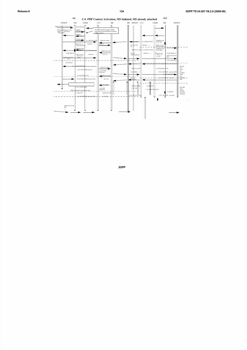
8/3/2019 3GPP TS 24007-V8.2.0
http://slidepdf.com/reader/full/3gpp-ts-24007-v820 134/149
3GPP
3GPP TS 24.007 V8.2.0 (2009-06)134Release 8
C.6 PDP Context Activation, MS Initiated, MS already attached
GRR-DATA-REQLL-UNITDATA-REQ
[PDU=Activate
PDP Context Req ]
[LLC-UI,
SAPI=signalling]
GRR-DATA-IND
[LLC-UI, TLLI
CI]
LL-UNITDATA-IND
[SM-PDU, …..]
GRR-DATA--REQ
[LLC-UI,
SAPI=signalling]
GRR-DATA-IND
[LLC-UI]
LL-UNITDATA-IND
[PDU= Activate
PDP Context
Accept ]
STOP TPDP Act
[ NSAPI, QoS ]
[ TLLI, NSAPI, QoS ]
SNSM-ACTIVATE
-IND
SNSM-ACTIVATE-
IND
START TPDPN act
No LLC
link
exists
yet,
establish
a link
and
exchange
XID
LLC link
exists
already,
only XID
exchange
SMREG- PDP-ACTIVATE-CNF
[ PDP-type, PDP-address,
QoS, NSAPI]
SNSM-ACTIVATE-
RSP
SNSM-
ACTIVATE-CNF
[ ]
[ TLLI ]
STOP TPDPN act
LL-XID-REQ
[ TL LI, SNDCP XID ]
LL-XID-CNF
[ TLLI,SNDCP-XID negotiated, N201 ]
LL-XID-IND
[ TLLI, SNCP-XID, N201 ]
LL-XID-RSP
[ TLLI, SNCP-XID negotiated]
GRR-DATA-REQ
[ LLC-XID,
SAPI=data ]
GRR-DATA-IND
[LLC XID]
GRR-DATA-IND
[ LLC XID, …..]
[LLC XID, priority=data]
LL- ESTABLISH-REQ
[ TLLI, SNDCP XID requested ]
LL-ESTABLISH- CNF
[ TLLI, SNDCP-XID negotiated, N201 ]
LL-ESTABLISH- IND
[ TLLI, SNCP-XID requested N201]
LL- ESTABLISH-RSP
[ TLLI, SNCP-XID negotiated ]
GRR-DATA-REQ
[ LLC-SABM,
SAPI=data ]
GRR-DATA-IND
[LLC UA]
GRR-DATA-IND
[ LLC SABM, .....]
[LLC UA,
SAPI=data]
LLC link exists
already, no
XID exchange
MS NET
GMMSNDCP LLC RR SM SNDCPLLCRR BSSGPSM GMM
SMREG-PDP- ACTIVATE-REQ
[ PDP-type, PDP address, QoS,
NSAPI, GGSN name,
ACK/UNACK ]
START TPDPact
GMMSM-
ESTABLISH-REQ
GMMSM-
ESTABLISH-CNF
GMMSM-UNIT
DATA-IND
[PDU= Activate
PDP Context Req ]
GMMSM-UNIT
DATA-REQ
[SM-PDU, ….. ]
GMMSM-UNIT
DATA-IND
[SM-PDU, ….. ]
LL-UNITDATA-REQ
[ PDU= Activate
PDP Context
Accept ]
[SM-PDU, …..]
GMMSM-UNIT
DATA-REQ
the GPRS Attach procedure shall be
performed in case the MS is not already
GPRS attached
XID re-negotiates requires link reset

8/3/2019 3GPP TS 24007-V8.2.0
http://slidepdf.com/reader/full/3gpp-ts-24007-v820 135/149
3GPP
3GPP TS 24.007 V8.2.0 (2009-06)135Release 8
C.7 PDP Context Activation, Network Initiated
RR-DATA-REQ
[ LLC-UI,
SAPI=signalling ]
GRR-DATA-IND
[ LLC-UI, ….. ]
[ PDP- type, PDP address,
QoS, NSAPI, GGSN name,
ACK/UNACK ]
GRR-DATA--REQ
[ LLC-UI,
SAPI=signalling ]
GRR-DATA-IND
[ LLC-UI ]
START TPDPN actSMREG-PDP-ACTIVATE-IND
STOP TPDPN act
MS NET
GMMSNDCP LLC RR SM SNDCPLLCRR BSSGPSM GMM
Continued as normal MS initiated PDP context activation
LL-UNITDATA-REQ
[ PDU= Request-
PDP Context-
Activation]
[SM-PDU, …..]
GMMSM-UNIT
DATA-REQ
SMREG-PDP-ACTIVATE-REQ
[ PDP-type, PDP-address
QoS, NSAPI,
GGSN name,
ACK/NACK ]
LL-UNITDATA-IND
[SM-PDU, …..]
GMMSM-UNIT
DATA-IND
[PDU= Activate
PDP Context Req ]
LL-UNITDATA-REQ
[PDU=Activate
PDP Context Req ]
SMREG-PDP- ACTIVATE-REQ
[ PDP-type, PDP address, QoS,
NSAPI, GGSN name,ACK/UNACK ]
START TPDPact
GMMSM-UNITDATA-REQ
[SM-PDU, ….. ]
LL-UNITDATA-IND
[PDU= Request-
PDP Context-
Activation]
GMMSM-UNIT
DATA-IND
[SM-PDU, ….. ]

8/3/2019 3GPP TS 24007-V8.2.0
http://slidepdf.com/reader/full/3gpp-ts-24007-v820 136/149
3GPP
3GPP TS 24.007 V8.2.0 (2009-06)136Release 8
C.8 Anonymous PDP Context Activation
(Void)
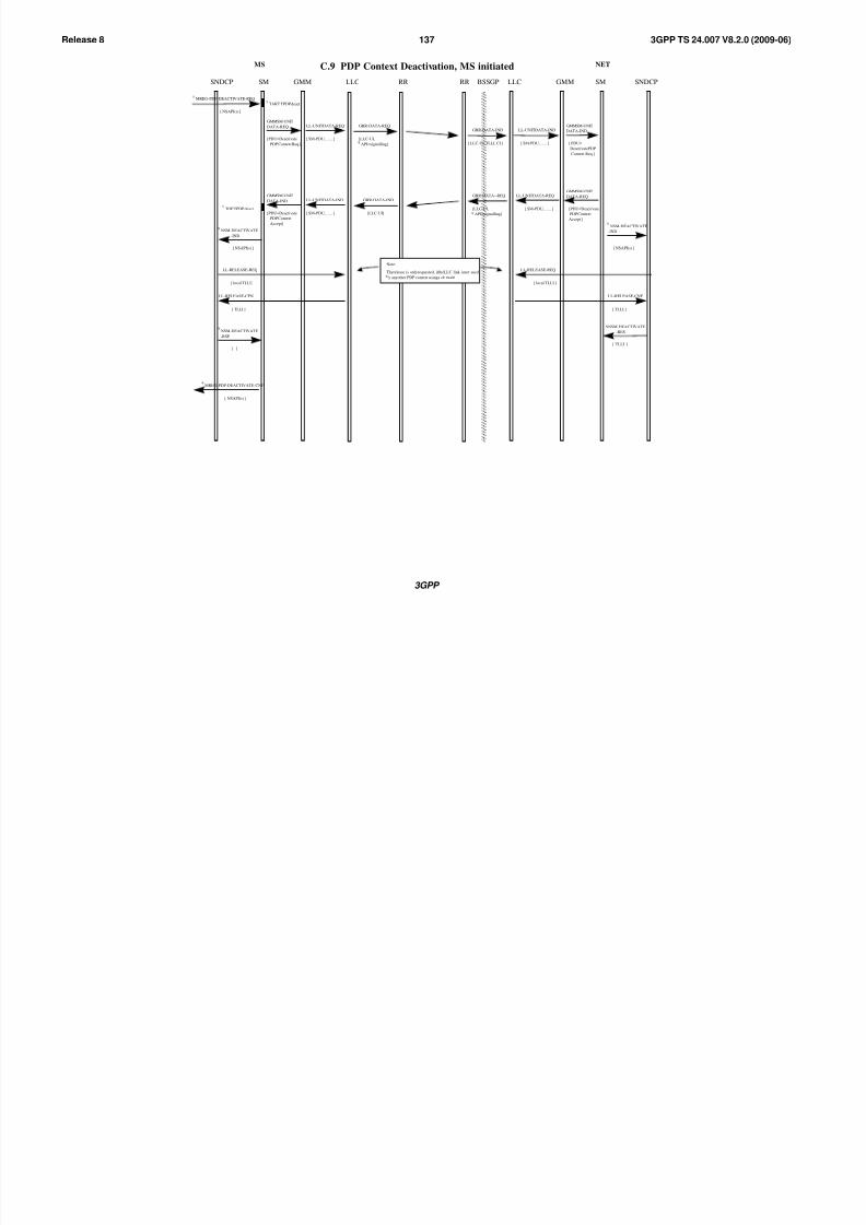
8/3/2019 3GPP TS 24007-V8.2.0
http://slidepdf.com/reader/full/3gpp-ts-24007-v820 137/149
3GPP
3GPP TS 24.007 V8.2.0 (2009-06)137Release 8
C.9 PDP Context Deactivation, MS initiated
MREG-PDP-DEACTIVATE-REQ
[ NSAPI(s) ]
TART TPDP deact
GRR-DATA-REQ
[LLC-UI,
API=signalling]
GRR-DATA-IND
[ LLC-UI, TLLI, CI ]
TOP TPDP deact
MREG-PDP-DEACTIVATE-CNF
[ NSAPI(s) ]
[ PDU=Deactivate
PDP ContextAccept ]
GRR-DATA--REQ
[LLC-UI,
API=signalling]
GRR-DATA-IND
[LLC-UI]
MS NET
GMMSNDCP LLC RR SM SNDCPLLCRR BSSGPSM GMM
LL-UNITDATA-REQ
[ PDU=Deactivate
PDP Context Req ]
[ SM-PDU, ….. ]
GMMSM-UNIT
DATA-REQ
LL-UNITDATA-IND
[ PDU=DeactivatePDP Context
Accept ]
[ SM-PDU, ….. ]
GMMSM-UNIT
DATA-IND
LL-UNITDATA-IND
[ PDU=
DeactivatePDP
Context Req ]
[ SM-PDU, ….. ]
GMMSM-UNIT
DATA-IND
LL-UNITDATA-REQ
[ SM-PDU, ….. ]
GMMSM-UNIT
DATA-REQ
[ NSAPI(s) ]
NSM-DEACTIVATE
-IND
SNSM-DEACTIVATE
-RES
[ TLLI ]
[ TLLI ]
LL-RELEASE-CNF
LL-RELEASE-REQ
[ local TLLI ]
LL-RELEASE-CFN
[ TLLI ]
[ ]
NSM-DEACTIVATE
-RSP
[ NSAPI(s) ]
NSM-DEACTIVATE
-IND
LL-RELEASE-REQ
[ local TLLI ]
Note:
Therelease is onlyrequested, iftheLLC link isnot used
y anyother PDP context usinga ck mode
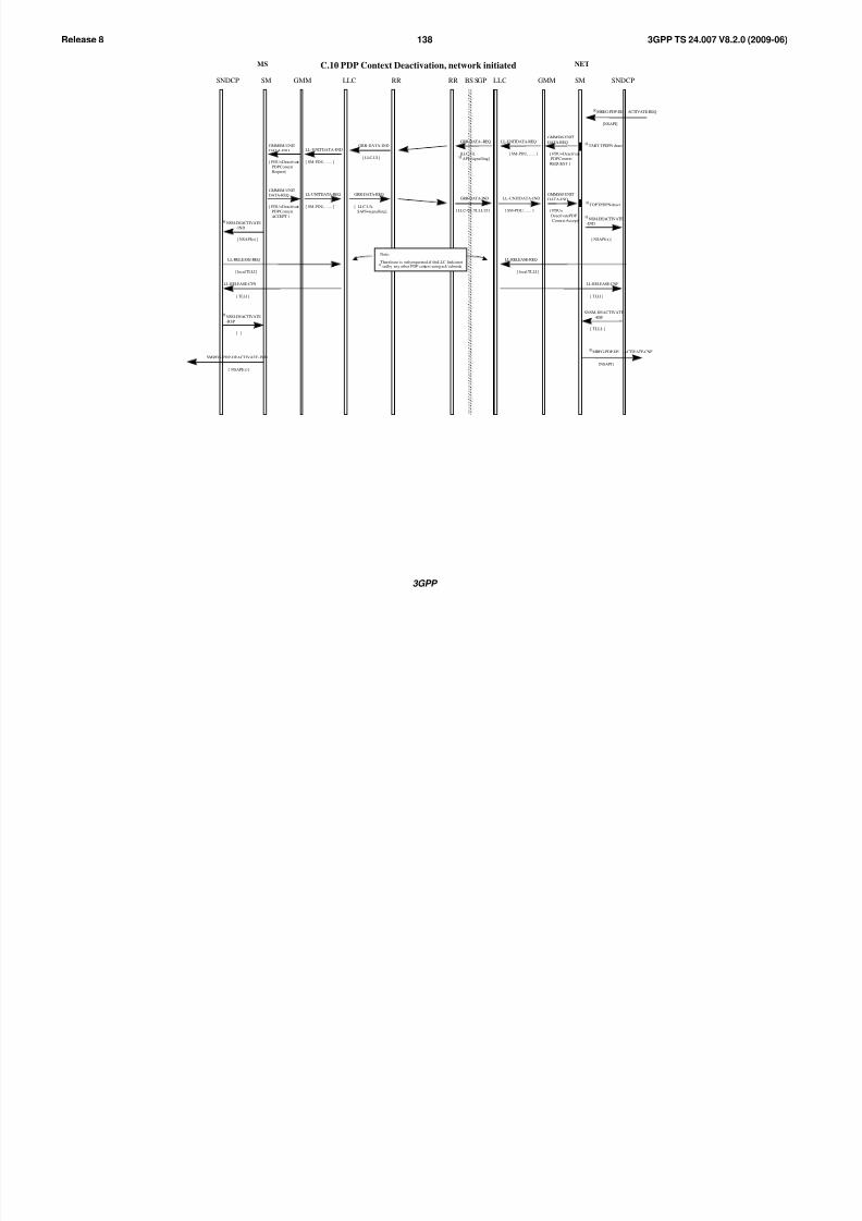
8/3/2019 3GPP TS 24007-V8.2.0
http://slidepdf.com/reader/full/3gpp-ts-24007-v820 138/149
3GPP
3GPP TS 24.007 V8.2.0 (2009-06)138Release 8
MS NET
GMMSNDCP LLC RR SM SNDCPLLCRR BS SGPSM GMM
C.10 PDP Context Deactivation, network initiated
TART TPDPN deact
TOP TPDPN deact
SMREG-PDP-DEACTIVATE-IND
[ NSAPI(s)]
GRR-DATA--REQ
[LLC-UI,
API=signalling]
GRR-DATA-IND
[ LLC-UI, TLLI, CI ]
GRR-DATA-IND
[ LLC-UI ]
GRR-DATA-REQ
[ LLC-UA,
SAPI=signalling ]
LL-UNITDATA-IND
[ PDU=Deactivate
PDP Context
Request]
[ SM-PDU, ….. ]
GMMSM-UNIT
DATA-IND
LL-UNITDATA-REQ
[ PDU=Deactivate
PDP ContextACCEPT ]
[ SM-PDU, ….. ]
GMMSM-UNIT
DATA-REQ
LL-UNITDATA-REQ
[ SM-PDU, ….. ]
GMMSM-UNIT
DATA-REQ
[ PDU=Deactivate
PDP Context
REQUEST ]
LL-UNITDATA-IND
[ PDU=
DeactivatePDP
Context Accept ]
[ SM-PDU, ….. ]
GMMSM-UNIT
DATA-IND
MREG-PDP-DE ACTIVATE-CNF
[NSAPI]
MREG-PDP-DE ACTIVATE-REQ
[NSAPI]
[ NSAPI(s) ]
NSM-DEACTIVATE
-IND
SNSM-DEACTIVATE
-RSP
[ TLLI, ]
[ TLLI ]
LL-RELEASE-CNF
LL-RELEASE-REQ
[ local TLLI ]
LL-RELEASE-CFN
[ TLLI ]
[ ]
NSM-DEACTIVATE
-RSP
[ NSAPI(s) ]
NSM-DEACTIVATE
-IND
LL-RELEASE-REQ
[ local TLLI ]
Note:
Therelease is onlyrequested, if theLLC link isnotsedby any other PDP context using ack’edmode
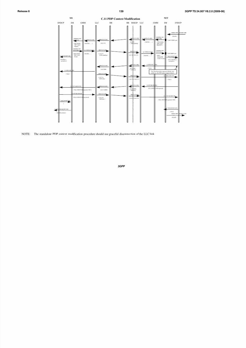
8/3/2019 3GPP TS 24007-V8.2.0
http://slidepdf.com/reader/full/3gpp-ts-24007-v820 139/149
3GPP
3GPP TS 24.007 V8.2.0 (2009-06)139Release 8
C.11 PDP Context Modification
TART TPDPN mod
[ TLLI, NSAPI(s) +
newQoS(s) ]
NSM-MODIFY-IND
NSM-MODIFY-RES
[ TLLI ]
TOP TPDPN mod
MREG-PDP-MODIFY-IND
[ NSAPI(s)/QoS(s) ]
LL- ESTABLISH-IND
[ TLLI, SNDCP XID requested, N201 ]
LL-ESTABLISH-RSP
[ TLLO, SNDCP-XID negotiated]LL- ESTABLISH-CNF
[ TLLI, SNCP-XID negotiated, N201]
[ NSAPI(s) +
newQoS(s) ]
NSM-MODIFY-IND
NSM-MODIFY-RSP
[ ]
MS NET
GMMSNDCP LLC RR SM SNDCPLLCRR BSSGPSM GMM
GRR-DATA-IND
[ LLC-UI, TLLI, CI ]
GRR-DATA-IND
[ LLC-UA, TLLI, CI ]
GRR-DATA-IND
[ LLC-UI, TLLI, CI ]
GRR-DATA--REQ
[LLC-UI,
API=signalling]
GRR-DATA--REQ
[LLC-DISC,
API=data]
GRR-DATA--REQ
[LLC-SABM,
API=data]
GRR-DATA-IND
[ LLC-UI ]
GRR-DATA-IND
[ LLC-DISC ]
GRR-DATA-IND
[ LLC-SABM]
GRR-DATA-REQ
[ LLC-UA,
SAPI=data ]
GRR-DATA-REQ
[ LLC-UA,
SAPI=data ]
GRR-DATA-REQ
[ LLC-UI,
SAPI=signalling]
LL-UNITDATA-REQ
[ SM-PDU, ….. ]
GMMSM-UNIT
DATA-REQ
[ PDU=Modify
PDP Context
REQUEST ]
LL-UNITDATA-IND
[ PDU=
ModifyPDP
Context Accept ]
[ SM-PDU, ….. ]
GMMSM-UNIT
DATA-IND
[ TLLI ]
LL-RELEASE- REQ
LL- RELEASE-CNF
[ TLLI ]
[ TLLI, SNDCP-XID requested]
LL-ESTABLISH-REQ
LL-RELEASE--IND
[ TLLI ]
LL-UNITDATA-REQ
[ PDU=Modify
PDP Context
Accept]
[ SM-PDU, ….. ]
GMMSM-UNIT
DATA-REQ
LL-UNITDATA-IND
[ PDU=Modify
PDP Context
Request]
[ SM-PDU, ….. ]
GMMSM-UNIT
DATA-IND
SMREG-PDP- MODIFY-CNF
[NSAPI]
SMREG-PDP- MODIFY-REQ
[NSAPI]
Note:Thereleaseisonly requested, ifthelink isnot
usedbyany other PDP context usingack’edmode
NOTE: The standalone PDP context modification procedure should use graceful disconnection of the LLC link.
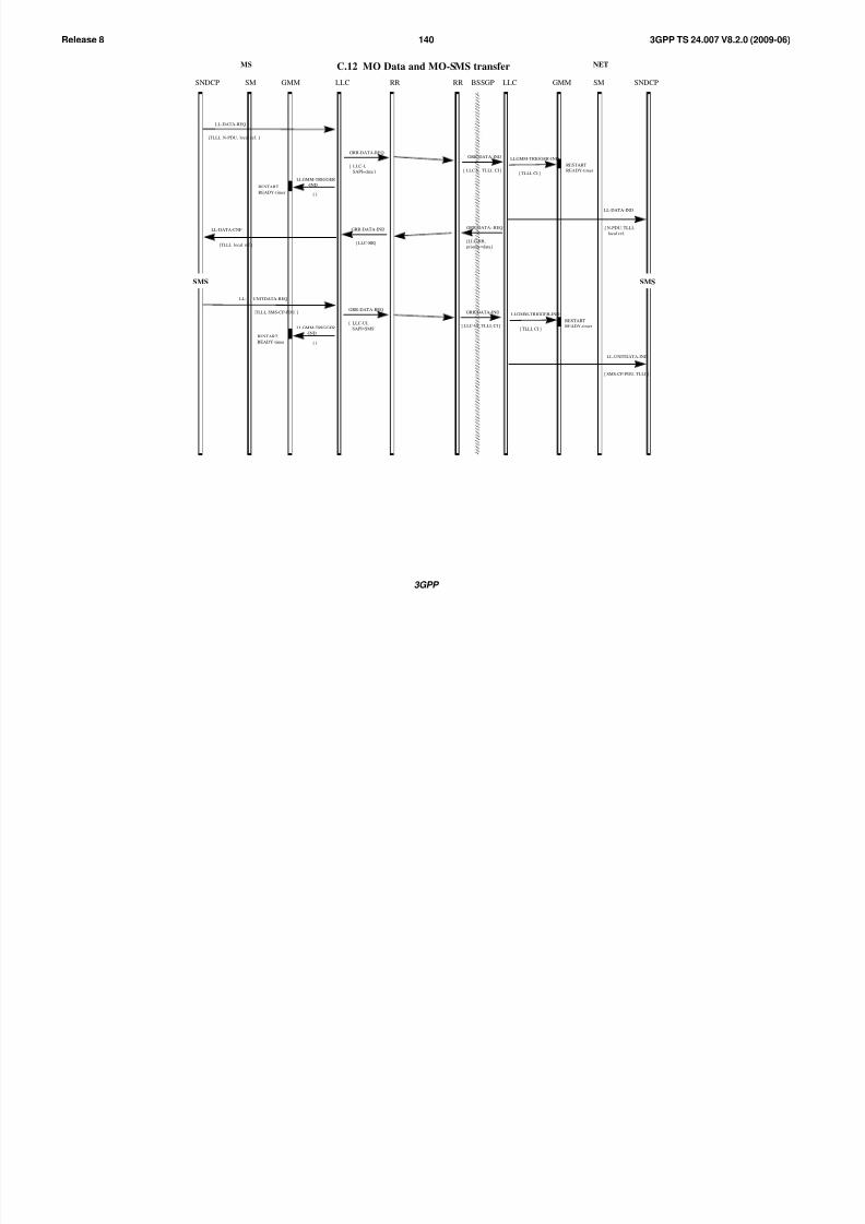
8/3/2019 3GPP TS 24007-V8.2.0
http://slidepdf.com/reader/full/3gpp-ts-24007-v820 140/149
3GPP
3GPP TS 24.007 V8.2.0 (2009-06)140Release 8
MS NET
GMMSNDCP LLC RR SM SNDCPLLCRR BSSGPSM GMM
C.12 MO Data and MO-SMS transfer
LL-DATA-REQ
[TLLI, N-PDU, local ref. ]
LLGMM-TRIGGER-IND
[ TLLI, CI ]
RESTART
READY-timer
LL-DATA-IND
[ N-PDU, TLLI,
local ref. ]LL-DATA-CNF
[TLLI, local ref.]
LLGMM-TRIGGER
-IND
[ ]
RESTART
READY-timer
SMS SMS
LL- UNITDATA-REQ
[TLLI, SMS-CP-PDU ]
RESTART
READY-timer
LL-UNITDATA-IND
[ SMS-CP-PDU, TLLI ]
RESTART
READY-timer
GRR-DATA--REQ
[LLC-RR,
priority=data]
GRR-DATA-IND
[ LLC-I, TLLI, CI ]
GRR-DATA-IND
[ LLC-UI, TLLI, CI ]
GRR-DATA-IND
[ LLC-RR]
GRR-DATA-REQ
[ LLC-UI,
SAPI=SMS ]
GRR-DATA-REQ
[ LLC-I,
SAPI=data ]
LLGMM-TRIGGER
-IND
[ ]
LLGMM-TRIGGER-IND
[ TLLI, CI ]

8/3/2019 3GPP TS 24007-V8.2.0
http://slidepdf.com/reader/full/3gpp-ts-24007-v820 141/149
3GPP
3GPP TS 24.007 V8.2.0 (2009-06)141Release 8
MS NET
GMMSNDCP LLC RR SM SNDCPLLCRR BSSGPSM GMM
C.13 Paging and MT Data transfer
LLGMM-TRIGGER-REQ
[ ]GRR-DATA-IND
[LLC PDU, TLLI,CI]
GMMRR-PAGE-REQGMMRR-PAGE-IND
LL-DATA-REQ
[ N-PDU, TLLI,local ref. ]
[TLLI, IMSI, CIor CI-list or RAI,SAPI=signalling ]
LLGMM-PAGE-IND
[ TLLI ]
[ ]
RESTARTREADY-timer
READY-timerexpires
LL-DATA-IND
[ TLLI, N-PDU, local ref. ]
RESTARTREADY-timer LLGMM-TRIGGER-IND
[ TLLI, CI]
RESTARTREADY-timer
LL-DATA-CNF
[ TLLI, local ref. ]
Normal LLC traffic continues
START PAGINGtimer
STOP PAGINGtimer
LLGMM-SUSPEND-REQ
[ TLLI, cause ]
A LLC frame issent, see ‘Cell update’, C17
RESTARTREADY-timer LLGMM-TRIGGER-
RESP-IND
[ TLLI, CI ]
GRR-DATA--REQ
[LLC-I,SAPI=data]
GRR-DATA-IND
[ LLC-RR, TLLI, CI ]
LLC is resumed,MM in READY
LLGMM-RESUME-REQ
[ TLLI ]GRR-DATA-IND
[ LLC-I]
GRR-DATA-REQ
[ LLC-PDU,SAPI=data ]
GRR-DATA-REQ
[ LLC-RR,SAPI=data ]
LLGMM-TRIGGER-IND
[ ]
LLC is suspended,MM in STANDBY,cause indicates that paging isrequired if data has to be sent
LL-DATASENT-IND
[ [TLLI, local ref.,
V(S)]
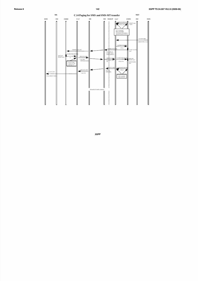
8/3/2019 3GPP TS 24007-V8.2.0
http://slidepdf.com/reader/full/3gpp-ts-24007-v820 142/149
3GPP
3GPP TS 24.007 V8.2.0 (2009-06)142Release 8
C.14 Paging for SMS and SMS-MT transferMS NET
GMMSMS LLC RR SM SMSLLCRR BSSGPSM GMM
LL-DATA-REQ
[SMS-CP-PDU, TLLI ]
LLGMM-PAGE-IND
READY-timer
expires
LLC is suspended,
MM in STANDBY,
cause indicates that paging is
required if data has to be sent
LLGMM-SUSPEND-REQ
[ TLLI, cause ]
[ TLLI ]
LLGMM-TRIGGER-REQ
[ ]GRR-DATA-IND
[LLC PDU, TLLI,
CI]
GMMRR-PAGE-REQGMMRR-PAGE-IND
[TLLI, IMSI, CI
or CI-list or RAI,
SAPI=signalling ]
[ ]
RESTART
READY-timer
LL-DATA-IND
[ TLLI, SMS-CP--PDU]
Normal LLC traffic continues
START PAGING
timer
STOP PAGING
timerAn LLC frame
is sent, see ‘Cell
updating’ C17
RESTART
READY-timerLLGMM-TRIGGER-IND
[ TLLI, CI ]
GRR-DATA--REQ
[LLC-UI,
SAPI=SMS]
LLC is resumed,
MM in READY
LLGMM-RESUME-REQ
[ TLLI ]GRR-DATA-IND
[ LLC-UI]
GRR-DATA-REQ
[ LLC-PDU,
SAPI=data/unitdata ]

8/3/2019 3GPP TS 24007-V8.2.0
http://slidepdf.com/reader/full/3gpp-ts-24007-v820 143/149
3GPP
3GPP TS 24.007 V8.2.0 (2009-06)143Release 8
MS NET
GMMSNDCP LLC RR SM SNDCPLLCRR BSSGPSM GMM
C.15 Generic Routing Area Update, Intra SGSN
START
Trams
LL-UNITDATA
-IND
[PDU= RA Update Req (
TLLI plus RAI),
oldTLLI, CI ]
Security function may be invoked
LL-UNITDATA-
REQ
[ PDU=
RA Update Req (
TLLI plus old RAI),
Cipher=off ]
STOP
Trams
LL-UNITDATA-REQ
[PDU=RA Update-
Accept (newTLLI) ]
LL-UNITDATA-IND
[PDU=RA Update-
Accept (newTLLI) ]
LLGMM-ASSIGN-REQ
[ newTLLI ]
[PDU-RA Update Compl,
newTLLI, CI ]
LL_UNITDATA_IND
Stop Tran
LLGMM-ASSIGN-REQ
[ Rx: newTLLI or
oldTLLI
Tx: newTLLI ]
GMMRR-ASSIGN-REQ
[ new TLLI ]
Start Tran
LLGMM-ASSIGN
-REQ
[ unassign oldTLLI ]
LLGMM-SUSPEND
-REQ
[ ]
SMM-RESUME-
REQ
[ ]
GRR-DATA-REQ
[ LLC-UI,
SAPI=signalling ]
GRR-DATA-REQ
[ LLC-PDU,
SAPI=signalling ]
GRR-DATA-IND
[ LLC-UI]
GRR-DATA-IND
[LLC UI,
old TLLI, CI]
GRR-DATA-IND
[LLC PDU
new TLLI, CI]
LL-UNITDATA-
REQ
[ PDU=RA Update-
Compl,
Cipher=on ]
GRR-DATA--REQ
[LLC-UI,
SAPI=signalling ]
The oldTLLI may be a Local
TLLI, or a Foreign TLLI, or a
Random TLLI
LLGMM-ASSIGN-REQ
[ unassign oldTLLI ]
GMMRR-ASSIGN-REQ
[ unassign oldTLLI ]

8/3/2019 3GPP TS 24007-V8.2.0
http://slidepdf.com/reader/full/3gpp-ts-24007-v820 144/149
3GPP
3GPP TS 24.007 V8.2.0 (2009-06)144Release 8
MS NET
GMMSNDCP LLC RR SM SNDCPLLCRR BSSGPSM GMM
C.16 Routing Area Update, Inter SGSN
GRR-DATA-IND
[LLC-PDU,
oldTLLI, CI
LL-UNITDATA-IND
[PDU-Routing Area
UpdateRequest,
oldTLLI, CI ]]
Security function may be invoked
[ PDU=Kc, Algorith ]
GRR-DATA-REQ
[ LLC-UI,SAPI=signalling ]
STARTTrams
LL-UNITDATA-REQ
[ PDU-Routing
Area Update Request,
Cipher=off ]
LLGMM-SUSPEND-REQ
[ TLLI]See ‘Routing area update, inter SGSN, old
SGSN’ in the GTP protocol. The new SGSN
receives:
Receive N-PDU number if ack’ed mo de
is used
- MM and PDP contexts, with Send and
[Kc, Algorithm]
LLGMM-ASSIGN-REQ
RESET and IOV-UI sent, possibly together
with SNDCP/LLC XID exchange
RR-UNITDATA-REQ
RR-UNITDATA-IND
[ LLC-SABM, SAPI=data]
[ LLC-UA, TLLI, CI ]
LL-ESTABLISH-IND
LL-ESTABLISH-RSP
[SNDCP XID requested]
[SNDCP XID negotiated]
GRR-UNITDATA-IND
GRR-UNITDATA-REQ
[ LLC-SABM ]
[ LLC-UA, SAPI=data ]
LL-ESTABLISH-REQ
LL-ESTABLISH-CNF
SNSM-MODIFY-RSP
[SNDCP XID requeseted]
[SNDCP XID negotiated]
SNSM-MODIFY-IND
[TLLI, NSAPI, QoS]
[TLLI]
Establishment and/or XID
Negotiation, as required
Receive N-PDUs tunnelled from the old
SGSN. For ack’ed mode N-PDUs, N-PDU
number is also received if assigned.
GRR-UNITDATA-REQ
[Reset, IOV-UI, LLC-XID]
GRR-UNITDATA-IND
[ LLC-XID, TLLI, CI ]
LLGMM-RESET-REQ
[ TLLI]
[ TLLI]
LL-RESET-IND[ TLLI]
LLGMM-RESET-CNF
[ TLLI ]
GRR-UNITDATA-IND
[ Reset, IOV-UI, LLC-XID ]
GRR-UNITDATA-REQ
[ LLC-XID ]
LL-RESET-IND
SNDCP suspends transmissionfor NSAPIs using ack mode
SNDCP suspends transmissionfor NSAPIs using ack mode
Sent for every PDP context to becreated in the new SGSN
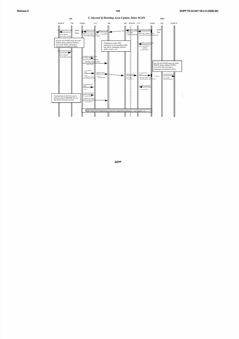
8/3/2019 3GPP TS 24007-V8.2.0
http://slidepdf.com/reader/full/3gpp-ts-24007-v820 145/149
3GPP
3GPP TS 24.007 V8.2.0 (2009-06)145Release 8
MS NET
GMMSNDCP LLC RR SM SNDCPLLCRR BSSGPSM GMM
PDP CONTEXT Modification may be requested (optional) – see figure C.11
[ oldTLLI ]
[
LLGMM-ASSIGN-REQ
nassign
GMMRR-ASSIGN-REQ
nassignoldTLLI ]
Unassignment of old TLLI may bedelayed so that SABM/XID sent onthe old TLLI may be received
C.16(cont’d) Routing Area Update, Inter SGSN
RR-DATA-IND
[LLC-PDU,
ewTLLI, CI ]
[
LLGMM-ASSIGN-REQ
nassignoldTLLI,]
GRR-DATA-REQ
[ LLC-UI,
API=signalling ][
[ PDU=
RAUpdate Compl
RxN-PDU number, Cipher]
LL-UNITDATA
-REQ
[ TLLI ]
LLGMM-RESUME-
-REQ
[PDU=RAUpdateCompl[
RxN-PDUnumber, newTLLI, CI ]
LL-UNITDATA
-IND
topTran
NSM-SEQUENCE-IND
[TLLI, NSAPI,[ RxN-PDUnumber]
Sent for each NSAPI using ack mode.SNDCP deletes buffered N-PDUsreceived by MS, and begin re-
transmitting all buffered N-PDUs.
GRR-DATA-REQ
[ LLC-PDU,
SAPI=signalling ]
LLGMM-ASSIGN-REQ
[ Rx: newTLLI or
oldTLLI
Tx: newTLLI ]
GMMRR-ASSIGN-REQ
[ new TLLI ]
LLGMM-ASSIGN-REQ
[ new TLLI, Kc, Algorithm
GRR-DATA-IND
[ LLC-PDU]
LL-UNITDATA-REQ
PDU= RA Update -Accept [
Rx N-PDU numbers, Cipher=on ]
START
Tran
Establishment and/or XID
negotiation on non-signalling SAPIs
may still be outstanding when RA
update accept is sent
STOP
Trams
SNSM-SEQUENCE-IND
[TLLI, NSAPI,
Rx N-PDU number]
Sent for each NSAPI using ack mode.
SNDCP deletes buffered N-PDUs
received by SGSN, and begin re-
transmitting all buffered N-PDUs.
LL-UNITDATA-IND
PDU= RA Update Accept [
Rx N-PDU numbers, Cipher]
SNSM-SEQUENCE-RES
[TLLI, NSAPI,
Rx N-PDU number]
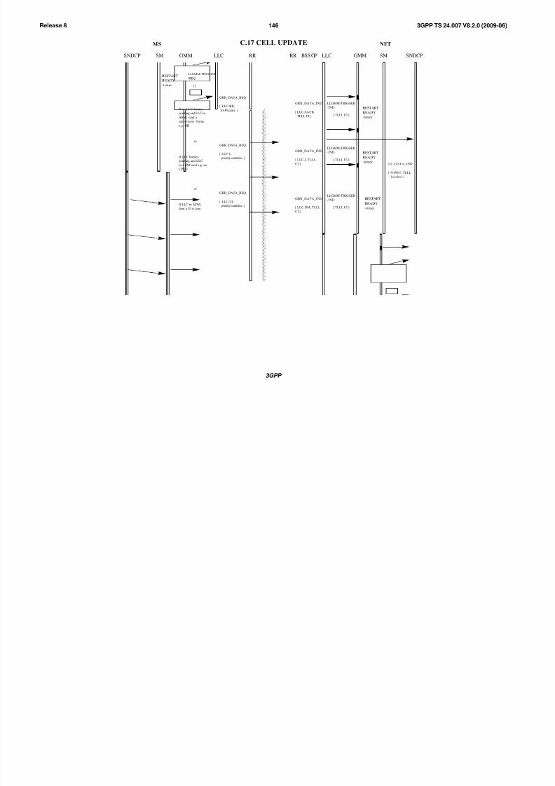
8/3/2019 3GPP TS 24007-V8.2.0
http://slidepdf.com/reader/full/3gpp-ts-24007-v820 146/149
3GPP
3GPP TS 24.007 V8.2.0 (2009-06)146Release 8
MS NET
GMMSNDCP LLC RR SM SNDCPLLCRR BSS GPSM GMM
LLGMM-TRIGGER
-REQ
[ ]
GRR_DATA_REQ
[ LLC-RR,
SAPI=data ]
GRR_DATA_IND
[ LLC-SACK,
TLLI, CI ]
LLGMM-TRIGGER
-IND
[ TLLI, CI ]
C.17 CELL UPDATE
GRR_DATA_REQ
[ LLC-I,
priority=unitdata ]
GRR_DATA_IND
[ LLC-I, TLLI,
CI ]
[ N-PDU, TLLI,
localref.]
LL_DATA_IND
If no LLC frames
pending and LLC in
ABM, send a
supervisory frame,
e.g. RR
If LLC frames
pending and LLC
in ABM send e.g. an
I PDU
RESTART
READY
-timer
RESTART
READY
-timer
or
LLGMM-TRIGGER
-IND
[ TLLI, CI ]
RESTART
READY
-timer
GRR_DATA_REQ
[ LLC-UI,
priority=unitdata ]
GRR_DATA_IND
[ LLC-DM, TLLI,
CI ]
If LLC in ADM,
then a UI is sent.
or
LLGMM-TRIGGER
-IND
[ TLLI, CI ]
RESTART
READY
-timer

8/3/2019 3GPP TS 24007-V8.2.0
http://slidepdf.com/reader/full/3gpp-ts-24007-v820 147/149
3GPP
3GPP TS 24.007 V8.2.0 (2009-06)147Release 8
MS NET
GMMNDCP LLC RR SM SNDCPLLCRR BSSGPSM GMM
LLGMM-TRIGGER
-REQ
GRR_DATA_REQ
[ LLC-RR,
SAPI=data ]
GRR_DATA_IND
[ LLC-SACK,
TLLI, CI ]
LLGMM-TRIGGER
-IND
[ TLLI, CI ,NULL]
C.18 CELL Notification
GRR_DATA_REQ
[ LLC-I,
priority=unitdata ]
GRR_DATA_IND
[ LLC-I, TLLI,
CI ]
[ N-PDU, TLLI,
local ref.]
LL_DATA_IND
If no LLC frames
pending and LLC in
ABM, send a
NULL frame
If LLC frames
pending and LLC
in ABM send e.g. an
I PDU
or
LLGMM-TRIGGER
-IND
[ TLLI, CI ]
RESTART
READY
-timer
GRR_DATA_REQ
[ LLC-UI,
priority=unitdata ]
GRR_DATA_IND
[ LLC-DM, TLLI,
CI ]
If LLC in ADM,
then a UI is sent.
or
LLGMM-TRIGGER
-IND
[ TLLI, CI ]
RESTART
READY
-timer
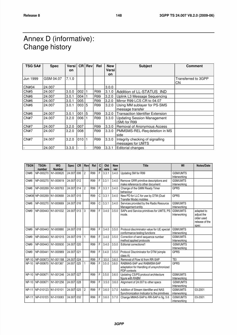
8/3/2019 3GPP TS 24007-V8.2.0
http://slidepdf.com/reader/full/3gpp-ts-24007-v820 148/149
3GPP
3GPP TS 24.007 V8.2.0 (2009-06)148Release 8
Annex D (informative):Change history
TSG SA# Spec Version
CR Rev Rel NewVersi
on
Subject Comment
Jun 1999 GSM 04.07 7.1.0 Transferred to 3GPPCN
CN#04 24.007 3.0.0
CN#5 24.007 3.0.0 002 1 R99 3.1.0 Addition of LL-STATUS_INDCN#6 24.007 3.0.1 004 1 R99 3.2.0 Uplink L3 Message Sequencing
CN#6 24.007 3.0.1 005 R99 3.2.0 Mirror R99 LCS CR to 04.07
CN#6 24.007 3.0.1 003 5 R99 3.2.0 Using MM sublayer for PS-SMSmessage transfer
CN#6 24.007 3.0.1 001 5 R99 3.2.0 Transaction Identifier Extension
CN#7 24.007 3.2.0 006 1 R99 3.3.0 Updating Session Management(SM) for R99
CN#7 24.007 3.2.0 007 R99 3.3.0 Removal of Anonymous Access
CN#7 24.007 3.2.0 008 R99 3.3.0 PMMSMS-REL-Req deletion in MSside
CN#7 24.007 3.2.0 010 1 R99 3.3.0 Integrity checking of signallingmessages for UMTS
- 24.007 3.3.0 - - R99 3.3.1 Editorial changes
TSGN TSGN-number
WGNumber
Spec CR Rev Rel Cat
Oldvers
Newver
Title WI Notes/Date
CN#8 NP-000270 N1-000620 24.007 006 2 R99 F 3.3.1 3.4.0 Updating SM for R99 GSM/UMTS
InterworkingCN#8 NP-000270 N1-000619 24.007 012 R99 F 3.3.1 3.4.0 Remove GRR primitive descriptions and
make reference to other documentGSM/UMTSInterworking
CN#8 NP-000269 N1-000763 24.007 014 2 R99 F 3.3.1 3.4.0 Change of the GMM Ready Timer behaviour
GPRS
CN#08 NP-000269 N1-000668 24.007 015 R99 C 3.3.1 3.4.0 New PD for LLC for use by DTM (DualTransfer Mode) mobiles
GPRS
CN#8 NP-000270 N1-000669 24.007 016 R99 C 3.3.1 3.4.0 Services provided by the Radio ResourceManagement entity
GSM/UMTSInterworking
CN#9 NP-000443 N1-001032 24.007 013 3 R99 F 3.4.0 3.5.0 SAPs and Service primitives for UMTS, PSmode.
GSM/UMTSInterworking
adapted toadjust theolder usedrelease of thespec
CN#9 NP-000443 N1-000880 24.007 018 R99 F 3.4.0 3.5.0 Protocol discriminator value for UE specialconformance testing functions
GSM/UMTSInterworking
CN#9 NP-000443 N1-001015 24.007 019 1 R99 F 3.4.0 3.5.0 Correction of send sequence number method applied protocols
GSM/UMTSInterworking
CN#9 NP-000443 N1-000930 24.007 020 R99 F 3.4.0 3.5.0 Editorial corrections!! GSM/UMTSInterworking
CN#9 NP-000441 N1-000969 24.007 021 R99 F 3.4.0 3.5.0 Protocol Discriminator for DTM (simpleclass A)
GPRS
NP-10 NP-000673 N1-001188 24.007 024 R99 F 3.5.0 3.6.0 Removal of Flow Id from RR-SAP TEI
NP-10 NP-000670 N1-001367 24.007 025 1 R99 F 3.5.0 3.6.0 RABMAS-SAP and RABMSM-SAPadaptation for Handling of unsynchronizedPDP contexts
GPRS
NP-10 NP-000671 N1-001246 24.007 027 R99 F 3.5.0 3.6.0 Updating CS/PS protocol architecturefigure with RABM
GSM/UMTSInterworking
NP-10 NP-000671 N1-001256 24.007 028 R99 F 3.5.0 3.6.0 Alignment of 24.007 to other specs GSM/UMTSInterworking
NP-11 NP-010123 N1-010101 24.007 025 2 R99 F 3.6.0 3.7.0 Addition of Stream Identifier and NAS
Synchronization Indicator to the primitives
GSM/UMTS
interworking
03-2001
NP-11 NP-010123 N1-010083 24.007 032 R99 F 3.6.0 3.7.0 Change MMAS-SAP to RR-SAP in fig. 5.6 GSM/UMTSinterworking
03-2001

8/3/2019 3GPP TS 24007-V8.2.0
http://slidepdf.com/reader/full/3gpp-ts-24007-v820 149/149
3GPP TS 24.007 V8.2.0 (2009-06)149Release 8
TSGN TSGN-number
WGNumber
Spec CR Rev Rel Cat
Oldvers
Newver
Title WI Notes/Date
NP-11 NP-010207 N1-010486 24.007 034 R99 F 3.6.0 3.7.0 Transfer of the N(SD) duplicationavoidance protocol from GSM 04.18
GSM/UMTSinterworking
03-2001
NP-11 NP-010205 N1-010447 24.007 035 R99 F 3.6.0 3.7.0 Deletion of cause 'unsynchronousPDP' inRABMAS-SAP
TEI 03-2001
NP-11 NP-010206 N1-010444 24.007 031 3 Rel-4 B 3.7.0 4.0.0 Adaptation of SS protocol to PS domain TEI 03-2001
NP-14 NP-010682 N1-011811 24.007 043 1 Rel-4 A 4.0.0 4.1.0 Clarification of the send sequence number mechanism
GSM/UMTSinterworking
12-2001
NP-16 NP-020218 N1-021341 24.007 047 2 Rel-4 A 4.1.0 4.2.0 RR protocol message type octet GSM/UMTSinterworking
06-2002
NP-16 NP-020222 N1-020893 24.007 049 1 Rel-4 A 4.1.0 4.2.0 Clarification of the extension mechanismfor type 4 IEs
TEI 06-2002
NP-16 NP-020224 N1-021367 24.007 053 1 Rel-4 F 4.1.0 4.2.0 Various clean-up of wrong references, egtowards 44.018 and 23.271
TEI4 06-2002
NP-16 24.007 Rel-5 4.2.0 5.0.0 Plenary decision to make this TS also for Rel-5.
06-2002
NP-17 NP-020383 N1-021836 24.007 057 1 Rel-5 F 5.0.0 5.1.0 Clarification of the CN release indicators TEI5 09-2002
NP-22 NP-030485 N1-031653 24.007 059 1 Rel-6 F 5.1.0 6.0.0 Don't use SAPI to differentiate betweenmessages of the same message type.
TEI6 12-2003
NP-24 NP-040185 N1-040967 24.007 063 1 Rel-6 A 6.0.0 6.1.0 Corrections concerning the use of the LCSprotocol
LCS 06-2004
NP-25 NP-040377 N1-041625 24.007 064 1 Rel-6 B 6.1.0 6.2.0 Update of the Session Management
services - MBMS
MBMS 09-2004
NP-25 NP-040375 N1-041645 24.007 067 4 Rel-6 B 6.1.0 6.2.0 Sequence number handling duringredirection in MOCN sharing scenario
NTShar 09-2004
NP-26 NP-040501 N1-04844 24.007 070 A 6.2.0 6.3.0 Sequence numbering for SS via PS TEI4 12-2004
NP-27 NP-050068 N1-050045 24.007 072 Rel-6 A 6.3.0 6.4.0 Addition of maximum data rate toRR_SYNC_IND and MMCC_SYNC_IND
SCUDIF 03-2005
CP-29 CP-050361 C1-050966 24.007 074 Rel-6 F 6.4.0 6.5.0 Use of short header format on SDCCH /FACCH
TEI6 09-2005
CP-29 CP-050366 C1-051030 24.007 075 1 Rel-7 F 6.5.0 7.0.0 Handling of the L2 Pseudo Length TEI7 09-2005
CP-42 CP-080866 C1-085163 24.007 0078 2 Rel-8 B 7.0.0 8.0.0 Support of EPS NAS protocols SAES 12-2008
CP-43 CP-090125 C1-091296 24.007 0082 2 Rel-8 F 8.0.0 8.1.0 UE side architecture figure without CSFB SAES 03-2009
CP-43 CP-090153 C1-091320 24.007 0083 2 Rel-8 F 8.0.0 8.1.0 Architecture figure for EPS UE + CSFB SAES-CSFB 03-2009
CP-43 CP-090130 C1-091182 24.007 0085 1 Rel-8 F 8.0.0 8.1.0 Message duplication in S1 mode SAES 03-2009
CP-43 CP-090125 C1-091106 24.007 0086 1 Rel-8 F 8.0.0 8.1.0 Add reference of LTE test controlspecification
SAES 03-2009
CP-43 CP-090126 C1-091350 24.007 0087 2 Rel-8 F 8.0.0 8.1.0 Clarification of format of LV-E/TLV-ELength Indicator format SAES 03-2009
Related Documents