3GPP TS 23.002 V7.6.0 (2008-12) Technical Specification 3rd Generation Partnership Project; Technical Specification Group Services and Systems Aspects; Network architecture (Release 7) GLOBAL SYSTEM FOR MOBILE COMMUNICATIONS R The present document has been developed within the 3 rd Generation Partnership Project (3GPP TM ) and may be further elaborated for the purposes of 3GPP. The present document has not been subject to any approval process by the 3GPP Organisational Partners and shall not be implemented. This Specification is provided for future development work within 3GPP only. The Organisational Partners accept no liability for any use of this Specification. Specifications and reports for implementation of the 3GPP TM system should be obtained via the 3GPP Organisational Partners' Publications Offices.

Welcome message from author
This document is posted to help you gain knowledge. Please leave a comment to let me know what you think about it! Share it to your friends and learn new things together.
Transcript

3GPP TS 23.002 V7.6.0 (2008-12)Technical Specification
3rd Generation Partnership Project;Technical Specification Group Services and Systems Aspects;
Network architecture(Release 7)
GLOBAL SYSTEM FOR MOBILE COMMUNICATIONS
R
The present document has been developed within the 3rd Generation Partnership Project (3GPP TM) and may be further elaborated for the purposes of 3GPP. The present document has not been subject to any approval process by the 3GPP Organisational Partners and shall not be implemented. This Specification is provided for future development work within 3GPP only. The Organisational Partners accept no liability for any use of this Specification.Specifications and reports for implementation of the 3GPP TM system should be obtained via the 3GPP Organisational Partners' Publications Offices.

3GPP
3GPP TS 23.002 V7.6.0 (2008-12)2Release 7
Keywords GSM, UMTS, network, architecture
3GPP
Postal address F-06921 Sophia Antipolis Cedex - FRANCE
Office address 650 Route des Lucioles - Sophia Antipolis
Valbonne - FRANCE Tel.: +33 4 92 94 42 00 Fax: +33 4 93 65 47 16
Internet http://www.3gpp.org
Copyright Notification
No part may be reproduced except as authorized by written permission. The copyright and the foregoing restriction extend to reproduction in all media.
© 2008, 3GPP Organizational Partners (ARIB, ATIS, CCSA, ETSI, TTA, TTC).
All rights reserved.
UMTS™ is a Trade Mark of ETSI registered for the benefit of its members 3GPP™ is a Trade Mark of ETSI registered for the benefit of its Members and of the 3GPP Organizational Partners LTE™ is a Trade Mark of ETSI currently being registered for the benefit of its Members and of the 3GPP Organizational Partners GSM® and the GSM logo are registered and owned by the GSM Association

3GPP
3GPP TS 23.002 V7.6.0 (2008-12)3Release 7
Contents
Foreword ............................................................................................................................................................8 Introduction ........................................................................................................................................................8 1 Scope ........................................................................................................................................................9 2 References ................................................................................................................................................9 3 Definitions and abbreviations.................................................................................................................12 3.1 Public Land Mobile Network (PLMN)............................................................................................................ 12 3.2 Core Network (CN) and Access Network (AN) .............................................................................................. 12 3.3 Circuit Switched (CS) and Packet Switched (PS) Domains ............................................................................ 13 3.3.1 CS Domain................................................................................................................................................. 13 3.3.2 PS Domain ................................................................................................................................................. 13 3.3a IP Multimedia subsystem (IMS) ................................................................................................................ 13 3.4 Location register .............................................................................................................................................. 13 3.5 Cell................................................................................................................................................................... 14 3.6 Base Station Controller (BSC) area ................................................................................................................. 14 3.7 Radio Network Controller (RNC) area ............................................................................................................ 14 3.8 Location Area (LA) ......................................................................................................................................... 14 3.9 Routing Area (RA) .......................................................................................................................................... 14 3.10 MSC area ......................................................................................................................................................... 14 3.11 VLR area.......................................................................................................................................................... 14 3.12 SGSN area ....................................................................................................................................................... 14 3.13 Zones for Regional Subscription ..................................................................................................................... 15 3.14 Service area...................................................................................................................................................... 15 3.15 Group call area................................................................................................................................................. 15 3.16 Pool-area.......................................................................................................................................................... 15 4 The basic entities of the mobile system .................................................................................................15 4.1 The Core Network (CN) entities...................................................................................................................... 15 4.1.1 Entities common to the PS and CS domains .............................................................................................. 15 4.1.1.1 The Home Subscriber Server (HSS)..................................................................................................... 15 4.1.1.1.1 The Home Location Register (HLR)............................................................................................... 16 4.1.1.1.2 The Authentication Centre (AuC)................................................................................................... 17 4.1.1.1.3 HSS logical functions ..................................................................................................................... 17 4.1.1.2 The Visitor Location Register (VLR)................................................................................................... 19 4.1.1.3 Void...................................................................................................................................................... 19 4.1.1.4 The Equipment Identity Register (EIR)................................................................................................ 19 4.1.1.5 SMS Gateway MSC (SMS-GMSC) ..................................................................................................... 20 4.1.1.6 SMS Interworking MSC (SMS-IWMSC) ............................................................................................ 20 4.1.1.7 Subscription Locator Function (SLF)................................................................................................... 20 4.1.2 Entities of the CS domain........................................................................................................................... 20 4.1.2.1 The Mobile-services Switching Centre (MSC) .................................................................................... 20 4.1.2.1.1 MSC Server..................................................................................................................................... 21 4.1.2.1.2 Circuit Switched - Media Gateway Function (CS-MGW).............................................................. 21 4.1.2.2 The Gateway MSC (GMSC) ................................................................................................................ 21 4.1.2.2.1 Gateway MSC Server (GMSC Server) ........................................................................................... 22 4.1.2.3 The Interworking Function (IWF) ........................................................................................................ 22 4.1.3 Entities of the PS domain ........................................................................................................................... 22 4.1.3.1 Serving GPRS Support Node (SGSN).................................................................................................. 22 4.1.3.2 Gateway GPRS Support Node (GGSN) ............................................................................................... 23 4.1.3.3 Border Gateway (BG)........................................................................................................................... 23 4.2 The Access Network (AN) entities .................................................................................................................. 23 4.2.1 The Base Station System (BSS) ................................................................................................................. 23 4.2.1.1 Base Station Controller (BSC) ............................................................................................................. 24 4.2.1.2 Base Transceiver Station (BTS) ........................................................................................................... 24

3GPP
3GPP TS 23.002 V7.6.0 (2008-12)4Release 7
4.2.2 The Radio Network System (RNS) ............................................................................................................ 24 4.2.2.1 Radio Network Controller (RNC) ........................................................................................................ 24 4.2.2.2 Node B.................................................................................................................................................. 24 4.3 The Mobile Station (MS)................................................................................................................................. 24 4a The specific entities of the mobile system .............................................................................................24 4a.1 The Group Call Register (GCR) entity ............................................................................................................ 24 4a.2 Void ................................................................................................................................................................. 25 4a.3 The Location Services (LCS) entities .............................................................................................................. 25 4a.3.1 Location Services (LCS) entities in RAN .................................................................................................. 25 4a.3.2 Gateway Mobile Location Centre (GMLC) ............................................................................................... 26 4a.3.3 Location Measurement Unit (LMU) .......................................................................................................... 26 4a.4 CAMEL entities............................................................................................................................................... 27 4a.4.1 GSM Service Control Function (gsmSCF) ................................................................................................ 27 4a.4.2 GSM Service Switching Function (gsmSSF) ............................................................................................. 27 4a.4.3 GSM Specialised Resource Function (gsmSRF)........................................................................................ 27 4a.4.4 GPRS Service Switching Function (gprsSSF) ........................................................................................... 27 4a.5 CBS-specific entities........................................................................................................................................ 27 4a.5.1 Cell Broadcast Centre (CBC)..................................................................................................................... 27 4a.6 Number Portability Specific entities ................................................................................................................ 27 4a.6.1 IN-based solution: Number Portability Database (NPDB)......................................................................... 28 4a.6.2 Signalling Relay-based solution: Mobile Number Portability/Signalling Relay function (MNP-SRF) ..... 28 4a.7 IP Multimedia (IM) Core Network (CN) Subsystem entities .......................................................................... 28 4a.7.1 Call Session Control Function (CSCF) ...................................................................................................... 28 4a.7.2 Media Gateway Control Function (MGCF) ............................................................................................... 28 4a.7.3 IP Multimedia Subsystem - Media Gateway Function (IMS-MGW)......................................................... 28 4a.7.4 Multimedia Resource Function Controller (MRFC) .................................................................................. 29 4a.7.4a Multimedia Resource Function Processor (MRFP) ................................................................................... 29 4a.7.5 Void............................................................................................................................................................ 29 4a.7.6 Breakout Gateway Control Function (BGCF)............................................................................................ 29 4a.7.7 Application Server (AS)............................................................................................................................. 29 4a.7.8 Interconnection Border Control Function (IBCF)...................................................................................... 30 4a.7.9 Transition Gateway (TrGW) ...................................................................................................................... 30 4a.7.10 Location Retrieval Function (LRF)............................................................................................................ 30 4a.8 Signalling Gateway Function (SGW) .............................................................................................................. 30 4a.9 Global Text Telephony Specific entities.......................................................................................................... 30 4a.10 Security Gateway (SEG).................................................................................................................................. 30 4a.11 Application Function (AF)............................................................................................................................... 31 4a.12 Void ................................................................................................................................................................. 31 4a.13 3GPP/WLAN Interworking entities................................................................................................................. 31 4a.13.1 WLAN UE ................................................................................................................................................. 31 4a.13.2 3GPP AAA Proxy ...................................................................................................................................... 31 4a.13.3 3GPP AAA Server ..................................................................................................................................... 31 4a.13.4 WLAN Access Gateway (WAG) ............................................................................................................... 31 4a.13.5 Packet Data Gateway (PDG)...................................................................................................................... 31 4a.14 Multimedia Broadcast Multicast Service (MBMS) specific entities................................................................ 31 4a.14.1 General ....................................................................................................................................................... 31 4a.14.2 Broadcast-Multicast Service Centre (BM-SC)........................................................................................... 32 4a.15 Void ................................................................................................................................................................. 32 4a.16 GUP Server...................................................................................................................................................... 32 4a.17 Policy and Charging Rules Function (PCRF) .................................................................................................. 32 4a.18 Policy and Charging Enforcement Function (PCEF)....................................................................................... 32 4a.19 Support of Short Message Service over generic 3GPP Internet Protocol access (SMSIP) specific entities .... 32 4a.19.1 General ....................................................................................................................................................... 32 4a.19.2 IP-Short-Message-Gateway (IP-SM-GW) ................................................................................................. 32 5 Configuration of a Public Land Mobile Network ..................................................................................32 5.1 Basic configuration.......................................................................................................................................... 32 5.2 Configuration of LCS entities.......................................................................................................................... 35 5.2.1 Configuration of LCS entities for GERAN................................................................................................ 35 5.2.2 Configuration of LCS entities for UTRAN................................................................................................ 36 5.3 Configuration of CAMEL entities ................................................................................................................... 36

3GPP
3GPP TS 23.002 V7.6.0 (2008-12)5Release 7
5.4 Configuration of CBS entities.......................................................................................................................... 37 5.5 Configuration of IM CN Subsystem entities.................................................................................................... 37 5.6 Configuration of Signalling Gateway Function ............................................................................................... 40 5.7 Configuration of 3GPP/WLAN Interworking.................................................................................................. 40 5.8 Configuration of Presence service ................................................................................................................... 41 5.9 Configuration of MBMS entities ..................................................................................................................... 41 5.10 Configuration of Short Message Service over generic 3GPP Internet Protocol access (SMSIP) entities........ 43 6 PLMN basic interfaces and reference points..........................................................................................43 6.1 Interfaces between Mobile Station and the Fixed Infrastructure ..................................................................... 44 6.1.1 Interface between Mobile Station and Base Station System (Um-interface) ............................................. 44 6.1.2 Interface between User Equipment and Radio Network System (Uu-interface)........................................ 44 6.2 Interface between the Core Network and the Access Network........................................................................ 44 6.2.1 Interfaces between the CS domain and the Access Network ..................................................................... 44 6.2.1.1 Interface between the MSC and Base Station System (A-interface) .................................................... 44 6.2.1.2 Interface between the MSC and Base Station System (Iu_CS interface) ............................................. 44 6.2.1.3 Interface between the MSC and RNS (Iu_CS interface) ...................................................................... 44 6.2.2 Interfaces between the PS domain and the Access Network...................................................................... 45 6.2.2.1 Interface between SGSN and BSS (Gb-interface) ................................................................................ 45 6.2.2.2 Interface between SGSN and BSS (Iu_PS-interface) ........................................................................... 45 6.2.2.3 Interface between SGSN and RNS (Iu_PS-interface) .......................................................................... 45 6.3 Interfaces internal to the Access Network ....................................................................................................... 45 6.3.1 Interface between BSC and BTS (Abis-interface) ..................................................................................... 45 6.3.2 Interface between RNC and Node B (Iub-interface) .................................................................................. 45 6.3.3 Interface between two RNCs (Iur-interface) .............................................................................................. 45 6.4 Interfaces internal to the Core Network........................................................................................................... 46 6.4.1 Interfaces internal to the CS domain .......................................................................................................... 46 6.4.1.1 Interface between the MSC server and its associated VLR (B-interface) ............................................ 46 6.4.1.2 Interface between the HLR and the MSC server (C-interface)............................................................. 46 6.4.1.3 Interface between the HLR and the VLR (D-interface)........................................................................ 46 6.4.1.4 Interface between MSC servers or MSC server and IP-SM-GW (E-interface) .................................... 46 6.4.1.5 Interface between MSC server and EIR (F-interface) .......................................................................... 47 6.4.1.6 Interface between VLRs (G-interface) ................................................................................................. 47 6.4.1.7 Reference point (G)MSC server – CS-MGW (Mc Reference Point) ................................................... 47 6.4.1.8 Reference Point MSC Server – GMSC Server (Nc Reference Point) .................................................. 47 6.4.1.9 Reference Point CS-MGW – CS-MGW (Nb Reference Point) ............................................................ 47 6.4.2 Interfaces internal to the PS domain........................................................................................................... 47 6.4.2.1 Interface between SGSN and HLR (Gr-interface)................................................................................ 47 6.4.2.2 Interface between SGSN and GGSN (Gn- and Gp-interface) .............................................................. 48 6.4.2.3 Signalling Path between GGSN and HLR (Gc-interface) .................................................................... 48 6.4.2.4 Interface between SGSN and EIR (Gf-interface) ................................................................................. 48 6.4.3 Interfaces used by CS and PS domains ...................................................................................................... 48 6.4.3.1 Interface between MSC/VLR and SGSN (Gs-interface) ...................................................................... 48 6.4.3.2 Interface between HLR and AuC (H-Interface).................................................................................... 48 6.4.3.3 Interface between SGSN/IP-SM-GW and SMS-GMSC/SMS-IWMSC (Gd-Interface)....................... 49 6a PLMN specific interfaces.......................................................................................................................49 6a.1 GCR-specific interface .................................................................................................................................... 49 6a.1.1 Interface between the MSC and its associated GCR (I-interface) .............................................................. 49 6a.2 Void ................................................................................................................................................................. 49 6a.3 LCS-specific interfaces.................................................................................................................................... 49 6a.3.1 LCS interfaces using MAP......................................................................................................................... 49 6a.3.2 Void............................................................................................................................................................ 49 6a.3.3 Void............................................................................................................................................................ 49 6a.3.4 Void............................................................................................................................................................ 49 6a.3.5 Interface between BSC and SMLC (Lb-interface) ..................................................................................... 49 6a.3.6 Interface between Peer SMLCs (Lp-interface)........................................................................................... 50 6a.3.7 Interface between BTS and LMU (Um-interface)...................................................................................... 50 6a.3.8 Interface between GMLC and External LCS Client (Le-interface)............................................................ 50 6a.3.9 Interface between RNS and Stand-Alone LMU, UE (Uu-interface) .......................................................... 50 6a.3.10 Interface between SRNC and SAS (Stand-Alone SMLC) (Iupc-interface) ............................................... 50 6a.3.11 Interface between GMLC and GMLC (Lr-interface) ................................................................................. 50

3GPP
3GPP TS 23.002 V7.6.0 (2008-12)6Release 7
6a.4 CAMEL-specific interfaces ............................................................................................................................. 50 6a.4.1 GMSC - gsmSSF interface ................................................................................................................... 50 6a.4.2 gsmSSF - gsmSCF interface................................................................................................................. 50 6a.4.3 MSC - gsmSSF interface ...................................................................................................................... 51 6a.4.4 gsmSCF - HLR interface ...................................................................................................................... 51 6a.4.5 gsmSCF - gsmSRF interface ................................................................................................................ 51 6a.4.6 MSC - gsmSCF interface...................................................................................................................... 51 6a.4.7 SGSN - gprsSSF interface .................................................................................................................... 51 6a.4.8 gprsSSF - gsmSCF interface (Ge Reference Point).............................................................................. 51 6a.5 CBS-specific interfaces.................................................................................................................................... 51 6a.5.1 Interface between the CBC and RNS (Iu_BC Interface)............................................................................ 51 6a.6 Number portability specific interfaces............................................................................................................. 52 6a.6.1 IN-based solution ....................................................................................................................................... 52 6a.6.1.1 NPDB to MSC interface ....................................................................................................................... 52 6a.6.2 Signalling Relay-based solution................................................................................................................. 52 6a.6.2.1 GMSC to MNP-SRF interface.............................................................................................................. 52 6a.6.2.2 MNP-SRF to HLR interface ................................................................................................................. 52 6a.7 IM Subsystem Reference Points ...................................................................................................................... 52 6a.7.1 Reference Point HSS - CSCF (Cx Reference Point) .................................................................................. 52 6a.7.2 Reference Point CSCF – UE (Gm Reference Point) .................................................................................. 52 6a.7.3 Reference Point MGCF – IMS-MGW (Mn Reference Point).................................................................... 52 6a.7.4 Reference Point MGCF – CSCF (Mg Reference Point)............................................................................. 53 6a.7.5 Void............................................................................................................................................................ 53 6a.7.6 Reference Point CSCF - MRFC (Mr Reference Point) .............................................................................. 53 6a.7.6a Reference Point MRFC – MRFP (Mp Reference Point) ............................................................................ 53 6a.7.7 Reference Point CSCF – CSCF (Mw Reference Point) ............................................................................. 53 6a.7.8 Void............................................................................................................................................................ 53 6a.7.9 Void............................................................................................................................................................ 53 6a.7.10 Reference Point CSCF – BGCF (Mi reference point)................................................................................ 53 6a.7.11 Reference Point BGCF – MGCF (Mj reference point) .............................................................................. 54 6a.7.12 Reference Point BGCF/IBCF – BGCF (Mk reference point) .................................................................... 54 6a.7.13 Reference Point CSCF- SLF (Dx Reference Point) ................................................................................... 54 6a.7.14 Reference Point to IPv6 network services (Mb reference point)................................................................ 54 6a.7.15 Reference Point S-CSCF – AS (ISC Reference Point)............................................................................... 54 6a.7.16 Reference Point HSS – SIP AS or OSA SCS (Sh Reference Point) .......................................................... 54 6a.7.17 Reference Point HSS – CAMEL IM-SSF (Si Reference Point)................................................................. 54 6a.7.18 Reference Point UE – AS (Ut Reference Point)......................................................................................... 54 6a.7.19 Reference Point AS- SLF (Dh Reference Point) ........................................................................................ 55 6a.7.20 Reference Point CSCF/BGCF - IBCF (Mx Reference Point) .................................................................... 55 6a.7.21 Reference Point IBCF - TrGW (Ix Reference Point) ................................................................................. 55 6a.7.22 Reference Point I-CSCF – AS (Ma Reference Point) ................................................................................ 55 6a.7.23 Reference Point P-CSCF – IMS Access Gateway (Iq Reference Point) .................................................... 55 6a.7.23a Reference Point E-CSCF – LRF (Ml Reference Point).............................................................................. 55 6a.8 Void ................................................................................................................................................................. 55 6a.9 Reference Points for 3GPP/WLAN Interworking............................................................................................ 55 6a.9.1 Reference point 3GPP AAA Server - HLR (D'/Gr' Reference Point) ........................................................ 55 6a.9.2 Reference point WLAN access network - 3GPP AAA Proxy/Server (Wa Reference Point)..................... 56 6a.9.3 Reference point 3GPP AAA Server – 3GPP AAA Proxy (Wd Reference Point) ...................................... 56 6a.9.4 Reference point 3GPP AAA Server/Proxy - WAG (Wg Reference Point) ................................................ 56 6a.9.5 Reference point PDG - packet data networks (Wi Reference Point).......................................................... 56 6a.9.6 Reference Point 3GPP AAA Server/Proxy - PDG (Wm Reference Point) ................................................ 56 6a.9.7 Reference Point WAG - WLAN access network (Wn Reference Point) ................................................... 56 6a.9.8 Reference Point WAG - PDG (Wp Reference Point)................................................................................. 56 6a.9.9 Reference point WLAN UE - PDG (Wu Reference Point) ........................................................................ 56 6a.9.10 Reference point WLAN UE - WLAN access network (Ww Reference Point) .......................................... 57 6a.9.11 Reference point 3GPP AAA Server - HSS (Wx Reference Point)............................................................. 57 6a.9.12 Reference point 3GPP AAA Server - SLF (Dw reference point)............................................................... 57 6a.10 MBMS specific reference points ..................................................................................................................... 57 6a.10.1 Reference point GGSN – BM-SC (Gmb Reference Point) ........................................................................ 57 6a.11 Void ................................................................................................................................................................. 57 6a.12 Reference Points for 3GPP Generic User Profile (GUP)................................................................................. 57 6a.12.1 Reference Point GUP Server – Applications (Rg Reference Point)........................................................... 57

3GPP
3GPP TS 23.002 V7.6.0 (2008-12)7Release 7
6a.12.2 Reference Point GUP Server – HSS and Applications – HSS (Rp Reference Point)................................. 58 6a.13 Reference Points for Policy and Charging Control.......................................................................................... 58 6a.13.1 Reference Point PCEF - PCRF (Gx Reference Point)................................................................................ 58 6a.13.2 Reference Point PCRF - Application Function (Rx Reference Point)........................................................ 58 6a.14 SMSIP specific reference points...................................................................................................................... 58 6a.14.1 Reference point IP-SM-GW – HSS (J Reference Point) ............................................................................ 58 7 Reference points between the PLMN and other networks .....................................................................58 7.1 Reference point fixed networks - MSC............................................................................................................ 58 7.2 Reference point GGSN - packet data networks (Gi reference point)............................................................... 58 7.3 Reference point GMLC - external LCS Client (Le reference point)................................................................ 59 7.4 Reference Point CSCF/IBCF – Multimedia IP networks (Mm Reference Point)............................................ 59 7.5 Void ................................................................................................................................................................. 59 7.6 Reference point PDG - packet data networks (Wi reference point)................................................................. 59 7.7 Reference Point WAG – WLAN access network (Wn reference point) .......................................................... 59
Annex A (informative): Description for GLR-related entities and interfaces ..................................60 A.1 Normative references .............................................................................................................................60 A.2 Definitions related to Gateway Location Register (GLR)......................................................................60 A.2.1 Gateway Location Register (GLR) .................................................................................................................. 60 A.2.2 Intermediate Mobile-services Switching Centre (IM-MSC)............................................................................ 60 A.2.3 Intermediate GPRS Serving Node (IM-GSN) ................................................................................................. 60 A.3 The entities of the mobile system...........................................................................................................60 A.3.1 Gateway Location Register (GLR) .................................................................................................................. 60 A.3.2 Intermediate Mobile-services Switching Centre (IM-MSC)............................................................................ 61 A.3.3 Intermediate GPRS Serving Node (IM-GSN) ................................................................................................. 61 A.4 Configuration of a Public Land Mobile Network ..................................................................................61 A.4.1 Basic configuration with GLR introduction..................................................................................................... 61 A.5 PLMN interfaces ....................................................................................................................................62 A.5.1 Interface between the HLR and the GLR (GLa-interface)............................................................................... 62 A.5.2 Interface between the VLR and the GLR (GLb-interface) .............................................................................. 62 A.5.3 Interface between the SGSN and the GLR (GLc-interface) ............................................................................ 62 A.5.4 Interface between the GLR and the IM_MSC (GLd-interface) ....................................................................... 62 A.5.5 Interface between the GLR and the IM_GSN (GLe-interface)........................................................................ 62 A.5.6 Interface between the SMS-GMSC and the GLR (GLf-interface)................................................................... 63 A.5.7 Interface between the SMS-GMSC and the IM_MSC (GLg-interface)........................................................... 63 A.5.8 Interface between the MSC and the IM_MSC (GLh-interface)....................................................................... 63 A.5.9 Interface between the GMLC and the IM_MSC (GLi-interface)..................................................................... 63 A.5.10 Interface between the GGSN and the IM_GSN (GLj-interface)...................................................................... 63 A.5.11 Interface between the SGSN and the IM_GSN (GLk-interface) ..................................................................... 63
Annex B (informative): Change history ...............................................................................................64
3GPP
3GPP TS 23.002 V7.6.0 (2008-12)8Release 7
Foreword This Technical Specification (TS) has been produced by the 3rd Generation Partnership Project (3GPP).
The contents of the present document are subject to continuing work within the TSG and may change following formal TSG approval. Should the TSG modify the contents of the present document, it will be re-released by the TSG with an identifying change of release date and an increase in version number as follows:
Version x.y.z
where:
x the first digit:
1 presented to TSG for information;
2 presented to TSG for approval;
3 or greater indicates TSG approved document under change control.
y the second digit is incremented for all changes of substance, i.e. technical enhancements, corrections, updates, etc.
z the third digit is incremented when editorial only changes have been incorporated in the document.
Introduction This document presents the possible architectures of the Universal Mobile Telecommunication System (UMTS).
covering both UTRAN and GERAN radio access technologies.
Clause 3 of the document contains the definition of the PLMN entities.
Clause 4 of the document contains the description of the basic entities of the PLMN, and clause 4a contains the description of the specific entities of the PLMN.
Clause 5 of the document contains the configuration of the PLMN.
Clauses 6, 6a and 7 of the document contain the PLMN's basic and specific interfaces and reference points and the PLMN's interfaces towards other networks.

3GPP
3GPP TS 23.002 V7.6.0 (2008-12)9Release 7
1 Scope This document offers an overview of the PLMN and its architectures and configuration. The configuration and the functional entities of the PLMN and the interfaces between them are described on a general level in order to cope with possible implementations. These descriptions include interfaces between and within the core networks, the access networks, the user equipment, different service platforms, different domains and subsystems, and functional entities within domains and subsystems.
This document covers different architectural aspects with varying level of detail. In general, other specifications shall be referred to for further details; these specifications enable the reader to acquire the full understanding of a system or service feature.
Note that this document does not cover, or even list, all features of PLMNs.
2 References The following documents contain provisions which, through reference in this text, constitute provisions of the present document.
• References are either specific (identified by date of publication, edition number, version number, etc.) or non-specific.
• For a specific reference, subsequent revisions do not apply.
• For a non-specific reference, the latest version applies. In the case of a reference to a 3GPP document (including a GSM document), a non-specific reference implicitly refers to the latest version of that document in the same Release as the present document.
[1] [Void]
[1a] 3GPP TR 21.905: "Vocabulary for 3GPP Specifications".
[2] 3GPP TS 22.016: "International Mobile station Equipment Identities (IMEI)".
[2a] 3GPP TS 22.060: "General Packet radio Service (GPRS); Service description; Stage 1".
[2b] 3GPP TS 22.071: "Location Services (LCS); Service description; Stage 1".
[2c] 3GPP TS 22.078: "Customised Applications for Mobile network Enhanced Logic (CAMEL); Service description, Stage 1".
[3] 3GPP TS 23.003: " Numbering, addressing and identification".
[4] 3GPP TS 22.127: "Open Service Access (OSA)".
[5] 3GPP TS 23.008: "Organization of subscriber data".
[6] 3GPP TS 23.009: "Handover procedures".
[7] 3GPP TS 23.012: "Location Management Procedures".
[8] 3GPP TS 23.041: "Technical realization of Cell Broadcast Service (CBS)".
[9] [Void]
[9a] 3GPP TS 23.060: "General Packet Radio Service (GPRS); Service description; Stage 2".
[10] [Void]
[10a] 3GPP TS 43.064: "Digital cellular telecommunication system (Phase 2+); General Packet Radio service (GPRS); Overall description of the GPRS radio interface; Stage 2".

3GPP
3GPP TS 23.002 V7.6.0 (2008-12)10Release 7
[10b] 3GPP TS 25.305: "Stage 2 Functional Specification of UE Positioning in UTRAN".
[10c] 3GPP TS 23.078: "Customised Applications for Mobile network Enhanced Logic (CAMEL) Phase 3 - Stage 2".
[10d] 3GPP TS 43.059: "Functional Stage 2 Description of Location Services in GERAN"[11] ITU-T Recommendation Q.1214 (05/1995): "Distributed Functional Plane for Intelligent Network CS-1".
[11a] 3GPP TS 23.101: "General UMTS Architecture".
[11b] 3GPP TS 23.110: "UMTS Access Stratum); Services and Functions".
[12] 3GPP TS 24.002: "GSM - UMTS Public Land Mobile Network (PLMN) access reference configuration".
[13] 3GPP TS 48.001: "Base Station System - Mobile-services Switching Centre (BSS - MSC) interface; General aspects".
[14] 3GPP TS 48.002: "Base Station System - Mobile-services Switching Centre (BSS - MSC) interface; Interface principles".
[14a] 3GPP TS 25.410: "UTRAN Iu Interface: general aspects and principles".
[15] 3GPP TS 48.004: "Base Station System - Mobile-services Switching Centre (BSS - MSC) interface Layer 1 specification".
[16] 3GPP TS 48.006: "Signalling transport mechanism specification for the Base Station System - Mobile-services Switching Centre (BSS - MSC) interface".
[17] 3GPP TS 48.008: "Mobile-services Switching Centre - Base Station System (MSC - BSS) interface; Layer 3 specification".
[18] [Void]
[19] 3GPP TS 48.051: "Base Station Controller - Base Transceiver Station (BSC - BTS) interface; General aspects".
[20] 3GPP TS 48.052: "Base Station Controller - Base Transceiver Station (BSC - BTS) interface; Interface principles".
[21] 3GPP TS 48.054: "Base Station Controller - Base Transceiver Station (BSC - BTS) interface; Layer 1 structure of physical circuits".
[22] 3GPP TS 48.056: "Base Station Controller - Base Transceiver Station (BSC - BTS) interface; Layer 2 specification".
[23] 3GPP TS 48.058: "Base Station Controller - Base Transceiver Station (BSC - BTS) interface; Layer 3 specification".
[24] 3GPP TS 48.060: "In-band control of remote transcoders and rate adaptors for full rate traffic channels".
[25] 3GPP TS 48.061: "In-band control of remote transcoders and rate adaptors for half rate traffic channels".
[26] 3GPP TS 29.002: "Mobile Application Part (MAP) specification".
[27] 3GPP TS 22.228: "Service requirements for the IP Multimedia Core Network Subsystem".
[28] 3GPP TS 23.207: "End-to-end Quality of Service (QoS) concept and architecture".
[29] [Void].
[30] [Void].

3GPP
3GPP TS 23.002 V7.6.0 (2008-12)11Release 7
[31] 3GPP TS 29.007: "General requirements on interworking between the Public Land Mobile Network (PLMN) and the Integrated Services Digital Network (ISDN) or Public Switched Telephone Network (PSTN)".
[32] 3GPP TS 29.010: "Information element mapping between Mobile Station - Base Station System (MS – BSS) and Base Station System - Mobile-services Switching Centre (BSS - MSC); Signalling procedures and the Mobile Application Part (MAP)".
[33] 3GPP TS 29.011: "Signalling interworking for supplementary services".
[34] 3GPP TS 23.228: "IP Multimedia Subsystem (IMS); Stage 2".
[35] 3GPP TR 41.103: "GSM Release 5 specifications".
[36] 3GPP TR 43.051: "Technical Specification Group GSM/EDGE Radio Access Network; Overall description, Stage 2".
[37] 3GPP TS 23.226: "Global Text Telephony (GTT); Stage 2".
[38] 3GPP TS 26.226: "Cellular Text Telephone Modem; General Description".
[39] 3GPP TS 23.016:"Subscriber data management; Stage 2".
[40] 3GPP TS 23.066: "Support of Mobile Number Portability (MNP); Technical realization; Stage 2".
[41] 3GPP TS 43.068: "Voice Group Call Service (VGCS); Stage 2".
[42] 3GPP TS 43.069: "Voice Broadcast Service (VBS); Stage 2".
[43] 3GPP TS 23.205: "Bearer independent circuit switched core network; Stage 2".
[44] 3GPP TS 48.014: "Base Station System (BSS) – Serving GPRS Support Node (SGSN) interface; Gb interface Layer 1".
[45] 3GPP TS 48.016: "Base Station System (BSS) – Serving GPRS Support Node (SGSN) interface; Network service".
[46] 3GPP TS 48.018: "Base Station System (BSS) – Serving GPRS Support Node (SGSN); BSS GPRS Protocol (BSSGP)".
[47] 3GPP TS 48.031: "Serving Mobile Location Centre – Serving Mobile Location Centre (SMLC –SMLC); SMLCPP specification".
[48] 3GPP TS 29.016: "Serving GPRS Support Node (SGSN) – Visitor Location Register (VLR); Gs interface network service specification".
[49] 3GPP TS 29.018: "Serving GPRS Support Node (SGSN) – Visitor Location Register (VLR); Gs interface Layer 3 specification".
[50] 3GPP TS 49.031: "Network Location Services (LCS); Base Station System Application Part LCS extension (BSSAP-LE)".
[51] 3GPP TS 29.060: "GPRS Tunnelling Protocol (GTP) across the Gn and Gp Interface".
[52] ITU-T Recommendation H.248: "Gateway Control Protocol".
[53] ITU-T Recommendation E.164: "The International public telecommunication numbering plan".
[54] ITU-T Recommendation H.323: "Packet-based multimedia communications systems".
[55] 3GPP TS 44.071: "Mobile radio interface layer 3 Location Services (LCS) specification".
[56] 3GPP TS 23.271: "Functional stage 2 description of LCS".
[57] ITU-T Recommendation I.363-2 :"B-ISDN ATM Adaptation Layer (AAL) type 2 specification".
[58] ITU-T Recommendation H.245: "Control protocol for multimedia communication".

3GPP
3GPP TS 23.002 V7.6.0 (2008-12)12Release 7
[59] IETF RFC 768: "User Datagram Protocol".
[60] IETF RFC 1889: "RTP: A Transport Protocol for Real-Time Applications".
[61] IETF RFC 3261: "SIP: Session Initiation Protocol".
[62] OMA MLP TS: "Mobile Location Protocol", [http://www.openmobilealliance.org/].
[63] 3GPP TS 29.198: "Open Service Access (OSA) Application Programming Interface (API)".
[64] 3GPP TS 33.210: "3G Security; Network Domain Security; IP network layer security".
[65] 3GPP TS 23.236: "Intra Domain Connection of RAN Nodes to Multiple CN Nodes".
[66] 3GPP TS 25.453: "UTRAN Iupc interface PCAP signalling".
[67] 3GPP TS 23.234: "3GPP system to Wireless Local Area Network (WLAN) interworking".
[68] 3GPP TS 23.141: "Presence Service; Architecture and functional description".
[69] OMA RLP TS: "Roaming Location Protocol", [http://www.openmobilealliance.org/].
[70] 3GPP TS 23.246: "Multimedia Broadcast/Multicast Service (MBMS); Architecture and functional description".
[71] 3GPP TS 23.240: "3GPP Generic User Profile (GUP); Architecture (Stage 2)".
[72] 3GPP TS 33.222: "Generic Authentication Architecture (GAA); Access to network application functions using Hypertext Transfer Protocol over Transport Layer Security (HTTPS)".
[73] 3GPP TS 23.203: "Policy Control and Charging Architecture (Stage 2)".
[74] 3GPP TS 23.167: "IP Multimedia Subsystem (IMS) emergency sessions".
[75] 3GPP TS 23.204:" Support of Short Message Service (SMS) over generic 3GPP Internet Protocol (IP) access".
3 Definitions and abbreviations In addition to the abbreviations given in the remainder of this clause others are listed in TR 21.905 [1a].
The definitions of the entities of the mobile system are given in the next clause.
3.1 Public Land Mobile Network (PLMN) A Public Land Mobile Network (PLMN) is established and operated by an administration or Recognized Private Operating Agency (RPOA) for the specific purpose of providing land mobile telecommunications service services to the public. A PLMN may be regarded as an extension of networks (e.g. ISDN, corporate and public PDNs, etc); it is a collection of MSCs areas in CS domain and SGSN areas in PS domain within a common numbering plan (e.g. same National Destination Code) and a common routing plan. The MSCs are the functional interfaces between the fixed networks and a PLMN for call set-up in CS domain. The GGSN and the SGSN are the functional interfaces between the fixed networks and a PLMN for packet transmission in PS domain.
Functionally the PLMNs may be regarded as independent telecommunications entities even though different PLMNs may be interconnected through the ISDN/PSTN and PDNs for forwarding of calls or network information. A similar type of interconnection may exist for the interaction between the MSCs/SGSNs of one PLMN.
3.2 Core Network (CN) and Access Network (AN) The PLMN infrastructure is logically divided into a Core Network (CN) and an Access Network (AN) infrastructures, as defined in TS 23.101 [11a] and TS 23.110 [11b]. The CN is logically divided into a CS domain, a PS domain and an

3GPP
3GPP TS 23.002 V7.6.0 (2008-12)13Release 7
IM subsystem, as defined in next clause. The AN is called BSS for GSM and RNS for UMTS, as defined in clause "The Access Network".
3.3 Circuit Switched (CS) and Packet Switched (PS) Domains The CN is constituted of a Circuit Switched (CS) domain and a Packet Switched (PS) domain. These two domains differ by the way they support user traffic, as explained below.
These two domains are overlapping, i.e. they contain some common entities. A PLMN can implement only one domain or both domains.
3.3.1 CS Domain The CS domain refers to the set of all the CN entities offering "CS type of connection" for user traffic as well as all the entities supporting the related signalling. A "CS type of connection" is a connection for which dedicated network resources are allocated at the connection establishment and released at the connection release.
The entities specific to the CS domain are: MSC, GMSC, VLR. All the other CN entities defined in clause 4 "The basic entities of the mobile system" and not defined as PS domain specific entities (see following clause) are common to the CS and to the PS domains.
3.3.2 PS Domain The PS domain refers to the set of all the CN entities offering "PS type of connection" for user traffic as well as all the entities supporting the related signalling. A "PS type of connection" transports the user information using autonomous concatenation of bits called packets: each packet can be routed independently from the previous one.
The entities specific to the PS domain are the GPRS specific entities, i.e. SGSN and GGSN. All the other CN entities defined in clause 4 and not defined as CS domain specific entities (see previous clause) are common to the CS and to the PS domains.
3.3a IP Multimedia subsystem (IMS) The IM subsystem comprises all CN elements for provision of IP multimedia services comprising audio, video, text, chat, etc. and a combination of them delivered over the PS domain. The entities related to IMS are CSCF, MGCF, MRF, etc. as defined in the stage 2 of the IM subsystem TS 23.228 [34]. See TS 22.228 [27] for some service examples of IMS.
3.4 Location register To enable communication to a mobile station the network must know where this mobile station is located. This information is stored in a function named location register.
The location register is handled by four different entities.
- The Home Location Register (HLR).
The Home Location Register (HLR) is the location register to which a mobile subscriber is assigned for record purposes such as subscriber information.
- The Visitor Location Register (VLR).
The Visitor Location Register (VLR) is the location register for Circuit Switched (CS) services, other than the HLR, used by an MSC to retrieve information for, e.g. handling of calls to or from a roaming mobile station currently located in its area.
- The Serving GPRS Support Node (SGSN).
The location register function in the SGSN stores subscription information and location information for Packet Switched (PS) services for each subscriber registered in the SGSN.

3GPP
3GPP TS 23.002 V7.6.0 (2008-12)14Release 7
The SGSN is needed only in a PLMN which supports GPRS.
- The Gateway GPRS Support Node (GGSN).
The location register function in the GGSN stores subscription information and routeing information (needed to tunnel packet data traffic destined for a GPRS MS to the SGSN where the MS is registered) for each subscriber for which the GGSN has at least one PDP context active.
The GGSN is needed only in a PLMN which supports GPRS.
3.5 Cell The cell is an area of radio coverage identified by a Base station identification as defined in TS 23.003 [3].
3.6 Base Station Controller (BSC) area The Base Station Controller (BSC) area is an area of radio coverage consisting of one or more cells controlled by one BSC. The boundaries of a BSC area and a location area are independent; a location area may span the boundary between BSC area and a BSC area may span the boundary between location areas.
3.7 Radio Network Controller (RNC) area The Radio Network Controller (RNC) area is an area of radio coverage consisting of one or more cells controlled by one RNC. The boundaries of a RNC area and a location area are independent; a location area may span the boundary between RNC area and a RNC area may span the boundary between location areas.
3.8 Location Area (LA) The Location Area (LA) is defined as an area in which a mobile station may move freely without updating the VLR. A location area may include one or several cells.
3.9 Routing Area (RA) The Routing Area (RA) is defined as an area in which a mobile station, in certain operation modes, may move freely without updating the SGSN. A routing area may include one or several cells. A RA is always contained within a location area.
3.10 MSC area The MSC area is the part of the network covered by an MSC. An MSC area may consist of one or several location areas. An MSC area may also consist of one or several BSC areas.
3.11 VLR area The VLR area is the part of the network controlled by a VLR. A VLR area may consist of one or several MSC areas.
3.12 SGSN area The SGSN area is the part of the network served by an SGSN. An SGSN area may consist of one or several routing areas. An SGSN area may also consist of one or several BSC areas. There need not be a one to one relationship between SGSN area and MSC/VLR area.

3GPP
3GPP TS 23.002 V7.6.0 (2008-12)15Release 7
3.13 Zones for Regional Subscription A PLMN operator may define a number of regional subscription areas, each of which is a subset of the service area for an unrestricted mobile subscriber. A regional subscription area may be contained within the service area of a single PLMN, or may lie within the service areas of two or more PLMNs. Each regional subscription area consists of one or more zones; each zone is contained within the service area of a PLMN.
The definition of a mobile subscriber's regional subscription area is stored within the HLR per National Destination Code(s) (NDC) of a PLMN and is transferred to the VLRs and/or SGSNs of that PLMN. The VLR and/or SGSN evaluates this information to extract the restricted or accessible MSC and/or SGSN areas and location areas to which the mobile subscriber is allowed to roam. The VLR and/or SGSN informs the HLR if an entire MSC and/or SGSN area is restricted.
Zones for Regional Subscription and their handling are defined in TS 23.003 [3], TS 23.008 [5] and TS 29.002 [26].
3.14 Service area The service area is defined as an area in which a mobile subscriber can be reached by another (mobile or fixed) subscriber without the subscriber's knowledge of the actual location of the mobile station within the area. A service area may consist of several PLMNs. One service area may consist of one country, be a part of a country or include several countries. The location registration system associated with each service area must thus contain a list of all mobile stations located within that service area.
3.15 Group call area The group call area is a predefined area composed of one or a number of cells to which a particular Voice Group Call Service (VGCS) or Voice Broadcast Service (VBS) call is distributed. The composition of a group call area is predefined in the network. The group call area may include cells of more than one MSC area and cells of more than one PLMN.
3.16 Pool-area A pool area is an area where Intra Domain Connection of RAN Nodes to Multiple CN Nodes is applied. Within a pool-area an MS may roam without need to change the serving Core Network (CN) node. A pool-area is served by one or more CN nodes in parallel.
4 The basic entities of the mobile system To provide the mobile service as it is defined, it is necessary to introduce some specific functions. These functional entities can be implemented in different equipments or gathered. In any case, exchanges of data occur between these entities.
4.1 The Core Network (CN) entities
4.1.1 Entities common to the PS and CS domains
4.1.1.1 The Home Subscriber Server (HSS)
The HSS is the master database for a given user. It is the entity containing the subscription-related information to support the network entities actually handling calls/sessions.
A Home Network may contain one or several HSSs: it depends on the number of mobile subscribers, on the capacity of the equipment and on the organisation of the network.

3GPP
3GPP TS 23.002 V7.6.0 (2008-12)16Release 7
As an example, the HSS provides support to the call control servers in order to complete the routing/roaming procedures by solving authentication, authorisation, naming/addressing resolution, location dependencies, etc.
The HSS is responsible for holding the following user related information:
- User Identification, Numbering and addressing information;
- User Security information: Network access control information for authentication and authorization;
- User Location information at inter-system level: the HSS supports the user registration, and stores inter-system location information, etc.;
- User profile information.
The HSS also generates User Security information for mutual authentication, communication integrity check and ciphering.
Based on this information, the HSS also is responsible to support the call control and session management entities of the different Domains and Subsystems (defined in clauses 3.3 and 3.3a) of the operator as shown in figure 0-a.
RpGr Gc
Locationinformation
Subscriptioninformation
HSS
Cx D C
GUP Server CSCFGGSNSGSNMSC Server GMSC Server
Figure 0-a: Example of a Generic HSS structure and basic interfaces
The HSS may integrate heterogeneous information, and enable enhanced features in the core network to be offered to the application & services domain, at the same time hiding the heterogeneity.
The HSS consists of the following functionalities:
- IP multimedia functionality to provide support to control functions of the IM subsystem such as the CSCF. It is needed to enable subscriber usage of the IM CN subsystem services. This IP multimedia functionality is independent of the access network used to access the IM CN subsystem.
- The subset of the HLR/AUC functionality required by the PS Domain.
- The subset of the HLR/AUC functionality required by the CS Domain, if it is desired to enable subscriber access to the CS Domain or to support roaming to legacy GSM/UMTS CS Domain networks.
The HSS is considered as GUP Data Repository for IM CN Subsystem user related data. The RAF (Repository Access Function) provides the Rp reference point as described in TS 23.240 [71].
The organisation of the subscriber data is outlined in TS 23.008 [5]. It also indicates which numbers, addresses and identifiers specified in TS 23.003 [3] are stored in HSS.
4.1.1.1.1 The Home Location Register (HLR)
The HLR is shown in the Reference Architecture up to and including Rel-4.
The HLR can be considered a subset of the HSS that holds the following functionality:
3GPP
3GPP TS 23.002 V7.6.0 (2008-12)17Release 7
- The functionality required to provide support to PS Domain entities such as the SGSN and GGSN, through the Gr and Gc interfaces and the 3GPP AAA Server for the I-WLAN through the D'/Gr' interface. It is needed to enable subscriber access to the PS Domain services.
- The functionality required to provide support to CS Domain entities such as the MSC/MSC server and GMSC/GMSC server, through the C and D interfaces. It is needed to enable subscriber access to the CS Domain services and to support roaming to legacy GSM/UMTS CS Domain networks.
4.1.1.1.2 The Authentication Centre (AuC)
The AuC is shown in the Reference Architecture up to and including Rel-4.
The AuC can be considered a subset of the HSS that holds the following functionality for the CS Domain and PS Domain:
- The AuC is associated with an HLR and stores an identity key for each mobile subscriber registered with the associated HLR. This key is used to generate security data for each mobile subscriber:
- data which are used for mutual authentication of the International Mobile Subscriber Identity (IMSI) and the network;
- a key used to check the integrity of the communication over the radio path between the mobile station and the network;
- a key used to cipher communication over the radio path between the mobile station and the network.
- The AuC communicates only with its associated HLR over a non-standardised interface denoted the H-interface. The HLR requests the data needed for authentication and ciphering from the AuC via the H-interface, stores them and delivers them to the VLR and SGSN which need them to perform the security functions for a mobile station.
4.1.1.1.3 HSS logical functions
This clause provides a high level and not exhaustive description of HSS functionality.

3GPP
3GPP TS 23.002 V7.6.0 (2008-12)18Release 7
Wx
Applications
D C Gr Gc ShRp CxSi
gsmSCF
HSS
Mobility Management Identification handling
User security info. generation Service authorization support
User security support Access authorization
Service Provisioning support Application Services Support
Call / Session establishment support CAMEL Services Support
GUP Data Repository
CS Domain PS Domain IM CN subsystem
GUP Server
SGSN GGSNGMSC MSC / VLR CSCFIM-SSF
SIP Application Server
OSA SCS
3GPP AAA Server
Figure 0.b: HSS logical functions
- Mobility Management
This function supports the user mobility through CS Domain, PS Domain and IM CN subsystem.
- Call and/or session establishment support
The HSS supports the call and/or session establishment procedures in CS Domain, PS Domain and IM CN subsystem. For terminating traffic, it provides information on which call and/or session control entity currently hosts the user.
- User security information generation
- The HSS generates user authentication, integrity and ciphering data for the CS and PS Domains and for the IM CN subsystem. User security support
The HSS supports the authentication procedures to access CS Domain, PS Domain and IM CN subsystem services by storing the generated data for authentication, integrity and ciphering and by providing these data to the appropriate entity in the CN (i.e. MSC/VLR, SGSN, 3GPP AAA Server or CSCF).
- User identification handling
The HSS provides the appropriate relations among all the identifiers uniquely determining the user in the system: CS Domain, PS Domain and IM CN subsystem (e.g. IMSI and MSISDNs for CS Domain; IMSI, MSISDNs and IP addresses for PS Domain, private identity and public identities for IM CN subsystem).
- Access authorisation
The HSS authorises the user for mobile access when requested by the MSC/VLR, SGSN, 3GPP AAA Server or CSCF, by checking that the user is allowed to roam to that visited network.
3GPP
3GPP TS 23.002 V7.6.0 (2008-12)19Release 7
- Service authorisation support
The HSS provides basic authorisation for MT call/session establishment and service invocation. Besides, the HSS updates the appropriate serving entities (i.e., MSC/VLR, SGSN, 3GPP AAA Server, CSCF) with the relevant information related to the services to be provided to the user.
- Service Provisioning Support
- The HSS provides access to the service profile data for use within the CS Domain, PS Domain and/or IM CN subsystem. Application Services and CAMEL Services Support
The HSS communicates with the SIP Application Server and the OSA-SCS to support Application Services in the IM CN subsystem. It communicates with the IM-SSF to support the CAMEL Services related to the IM CN subsystem. It communicates with the gsmSCF to support CAMEL Services in the CS Domain and PS Domain.
- GUP Data Repository
The HSS supports the storage of IM CN Subsystem user related data, and provides access to these data through the Rp reference point.
4.1.1.2 The Visitor Location Register (VLR)
A mobile station roaming in an MSC area or within a pool-area is controlled by a Visitor Location Register. When a Mobile Station (MS) enters a new location area it starts a registration procedure. An MSC in charge of that area notices this registration and transfers to a Visitor Location Register the identity of the location area where the MS is situated. If this MS is not yet registered in the VLR, the VLR and the HLR exchange information to allow the proper handling of calls involving the MS.
A VLR may be in charge of one or several MSC areas.
The VLR contains also the information needed to handle the calls set-up or received by the MSs registered in its data base (for some supplementary services the VLR may have to obtain additional information from the HLR). The following elements are included:
- the International Mobile Subscriber Identity (IMSI);
- the Mobile Station International ISDN number (MSISDN);
- the Mobile Station Roaming Number (MSRN), see TS 23.003 [3] for allocation principles;
- the Temporary Mobile Station Identity (TMSI), if applicable;
- the Local Mobile Station Identity (LMSI), if used;
- the location area where the mobile station has been registered;
- the identity of the SGSN where the MS has been registered. Only applicable to PLMNs supporting GPRS and which have a Gs interface between MSC/VLR and SGSN;
- the last known location and the initial location of the MS.
The VLR also contains supplementary service parameters attached to the mobile subscriber and received from the HLR. The organisation of the subscriber data is outlined in TS 23.008 [5].
4.1.1.3 Void
4.1.1.4 The Equipment Identity Register (EIR)
The Equipment Identity Register (EIR) in the GSM system is the logical entity which is responsible for storing in the network the International Mobile Equipment Identities (IMEIs), used in the GSM system.
The equipment is classified as "white listed", "grey listed", "black listed" or it may be unknown as specified in TS 22.016 [2] and TS 29.002 [26].
This functional entity contains one or several databases which store(s) the IMEIs used in the GSM system.

3GPP
3GPP TS 23.002 V7.6.0 (2008-12)20Release 7
The mobile equipment may be classified as "white listed", "grey listed" and "black listed" and therefore may be stored in three separate lists.
An IMEI may also be unknown to the EIR.
An EIR shall as a minimum contain a "white list" (Equipment classified as "white listed").
See also TS 22.016 [2] on IMEI.
4.1.1.5 SMS Gateway MSC (SMS-GMSC)
The SMS Gateway MSC (SMS-GMSC) acts as an interface between a Short Message Service Centre and the PLMN, to allow short messages to be delivered to mobile stations from the Service Centre (SC).
The choice of which MSCs can act as SMS Gateway MSCs is a network operator matter (e.g. all MSCs or some designated MSCs).
4.1.1.6 SMS Interworking MSC (SMS-IWMSC)
The SMS Interworking MSC acts as an interface between the PLMN and a Short Message Service Centre (SC) to allow short messages to be submitted from Mobile Stations to the SC.
The choice of which MSCs can act as SMS Interworking MSCs is a network operator matter (e.g. all MSCs or some designated MSCs).
4.1.1.7 Subscription Locator Function (SLF)
The SLF:
- Is queried by the I-CSCF during the Registration and Session Setup to get the name of the HSS containing the required subscriber specific data. Furthermore the SLF is also queried by the S-CSCF during the Registration.
- Is queried by the AS in conjunction with the Sh interface operation to get the name of the HSS containing the required subscriber specific data.
- Is queried by the 3GPP AAA server to get the name of the HSS containing the required subscriber specific data.
- Is accessed via the Dx interface by the CSCF, via the Dh interface by the AS, and via the Dw interface by the 3GPP AAA Server.
The SLF is not required in a single HSS environment. An example for a single HSS environment is a server farm architecture. Use of SLF is not required when AS are configured/managed to use pre-defined HSS.
4.1.2 Entities of the CS domain
4.1.2.1 The Mobile-services Switching Centre (MSC)
The Mobile-services Switching Centre (MSC) constitutes the interface between the radio system and the fixed networks. The MSC performs all necessary functions in order to handle the circuit switched services to and from the mobile stations.
In order to obtain radio coverage of a given geographical area, a number of BSS and/or RNS are normally required; i.e. each MSC would thus have to interface to one or more BSS(s) and/or RNS(s). In addition several MSCs may be required to cover a country.
When Intra Domain Connection of RAN Nodes to Multiple CN Nodes is applied, all the MSCs serving a pool-area share the responsibility to serve the MSs located in the pool-area. All these MSCs interface to all the BSS(s) and/or RNS(s) forming the pool-area.
The Mobile-services Switching Centre is an exchange, which performs all the switching and signalling functions for mobile stations located in a geographical area designated as the MSC area. When Intra Domain Connection of RAN Nodes to Multiple CN Nodes is applied, one or more MSCs serve a pool-area, but each individual MS is served by only one out of these MSCs, as described in TS 23.236 [65]. The main difference between a MSC and an exchange in a fixed

3GPP
3GPP TS 23.002 V7.6.0 (2008-12)21Release 7
network is that the MSC has to take into account the impact of the allocation of radio resources and the mobile nature of the subscribers and has to perform in addition, at least the following procedures:
- procedures required for the location registration (see TS 23.012 [7]);
- procedures required for handover (see TS 23.009 [6]).
NOTE: When this improves the readability (e.g. when dealing with inter-releases handover), the term 2G-MSC can be used to refer to an MSC Release 98 or prior, and the term 3G-MSC can be used to refer to an MSC Release 99 or later.
When needed, the MSC can be implemented in two different entities: the MSC Server, handling only signalling, and the CS-MGW, handling user's data. A MSC Server and a CS-MGW make up the full functionality of a MSC.
4.1.2.1.1 MSC Server
The MSC Server mainly comprises the call control (CC) and mobility control parts of a MSC.
The MSC Server is responsible for the control of mobile originated and mobile terminated CC CS Domain calls. It terminates the user-network signalling and translates it into the relevant network – network signalling. The MSC Server also contains a VLR to hold the mobile subscriber's service data and CAMEL related data.
The MSC Server controls the parts of the call state that pertain to connection control for media channels in a CS-MGW.
4.1.2.1.2 Circuit Switched - Media Gateway Function (CS-MGW)
NOTE: In this document the term Media Gateway Function (MGW) is used when there is no need to differentiate between the CS domain entity and the IP Multimedia CN Subsystem entity. When referring specifically to the CS domain entity the term CS-MGW is used. When referring specifically to the IP Multimedia CN Subsystem entity, the term IMS-MGW is used.
This component is PSTN/PLMN transport termination point for a defined network and interfaces UTRAN with the core network over Iu.
A CS-MGW may terminate bearer channels from a switched circuit network and media streams from a packet network (e.g. RTP streams in an IP network). Over Iu, the CS-MGW may support media conversion, bearer control and payload processing (e.g. codec, echo canceller, conference bridge) for support of different Iu options for CS services (AAL2/ATM based as well as RTP/UDP/IP based).
The CS-MGW:
- Interacts with MGCF, MSC server and GMSC server for resource control.
- Owns and handles resources such as echo cancellers etc.
- May need to have Codecs.
The CS-MGW will be provisioned with the necessary resources for supporting UMTS/GSM transport media. Further tailoring (i.e. packages) of the H.248 [52] may be required to support additional Codecs and framing protocols, etc.
The CS-MGW bearer control and payload processing capabilities will also need to support mobile specific functions such as SRNS relocation/handover and anchoring. It is expected that current H.248 [52] standard mechanisms can be applied to enable this.
4.1.2.2 The Gateway MSC (GMSC)
If a network delivering a call to the PLMN cannot interrogate the HLR, the call is routed to an MSC. This MSC will interrogate the appropriate HLR and then route the call to the MSC where the mobile station is located. The MSC which performs the routing function to the actual location of the MS is called the Gateway MSC (GMSC).
The acceptance of an interrogation to an HLR is the decision of the operator.
The choice of which MSCs can act as Gateway MSCs is for the operator to decide (i.e. all MSCs or some designated MSCs).

3GPP
3GPP TS 23.002 V7.6.0 (2008-12)22Release 7
If the call is a voice group/broadcast call, it is routed directly from the GMSC to the VBS/VGCS Anchor MSC, based on information (VBS/VGCS call reference) contained in the dialled number (see also TS 43.068 [41] and TS 43.069 [42]).
Editor's note: There is a need to consider possibilities that call incoming to the PLMN may be routed to entities other than the GMSC, e.g., for networks that do not deploy CS domain.
When needed, the GMSC can be implemented in two different entities: the GMSC Server, handling only signalling, as defined below, and the CS-MGW, defined above. A GMSC Server and a CS-MGW make up the full functionality of a GMSC.
4.1.2.2.1 Gateway MSC Server (GMSC Server)
The GMSC server mainly comprises the call control and mobility control parts of a GMSC.
4.1.2.3 The Interworking Function (IWF)
The Interworking Function (IWF) is a functional entity associated with the MSC. The IWF provides the functionality necessary to allow interworking between a PLMN and the fixed networks (ISDN, PSTN and PDNs). The functions of the IWF depend on the services and the type of fixed network. The IWF is required to convert the protocols used in the PLMN to those used in the appropriate fixed network. The IWF may have no functionality where the service implementation in the PLMN is directly compatible with that at the fixed network. The interworking functions are described in TS 29.007 [31].
4.1.3 Entities of the PS domain The UMTS PS-domain (or GPRS) Support Nodes (GSN) are the Gateway GSN (GGSN) and the Serving GSN (SGSN). They constitute the interface between the radio system and the fixed networks for packet switched services. The GSN performs all necessary functions in order to handle the packet transmission to and from the mobile stations.
4.1.3.1 Serving GPRS Support Node (SGSN)
The location register function in the SGSN stores two types of subscriber data needed to handle originating and terminating packet data transfer:
- subscription information:
- the IMSI;
- one or more temporary identities;
- zero or more PDP addresses.
- location information:
- depending on the operating mode of the MS, the cell or the routeing area where the MS is registered;
- the VLR number of the associated VLR (if the Gs interface is implemented);
- the GGSN address of each GGSN for which an active PDP context exists.
The organisation of the subscriber data in the SGSN is defined in TS 23.008 [5] and TS 23.060 [9a].
The procedures for information transfer between the SGSN, the GGSN, the VLR and the HLR are defined in TS 23.016 [39] and TS 23.060 [9a].
NOTE: When this improves the readability (e.g. when dealing with inter-releases handover), the term 2G-SGSN can be used to refer to an MSC Release 98 or prior, and the term 3G-SGSN can be used to refer to an MSC Release 99 or later.

3GPP
3GPP TS 23.002 V7.6.0 (2008-12)23Release 7
4.1.3.2 Gateway GPRS Support Node (GGSN)
The location register function in the GGSN stores subscriber data received from the HLR and the SGSN. There are two types of subscriber data needed to handle originating and terminating packet data transfer:
- subscription information:
- the IMSI;
- zero or more PDP addresses.
- location information:
- the SGSN address for the SGSN where the MS is registered.
The organisation of the subscriber data in the GGSN is defined in TS 23.008 [5] and TS 23.060 [9a].
The procedures for information transfer between the GGSN, the SGSN and the HLR are defined in TS 23.016 [39] and TS 23.060 [9a].
4.1.3.3 Border Gateway (BG)
The Border Gateway (BG) is a gateway between a PLMN supporting GPRS and an external inter-PLMN backbone network used to interconnect with other PLMNs also supporting GPRS. The role of the BG is to provide the appropriate level of security to protect the PLMN and its subscribers.
The BG is only needed in PLMNs supporting GPRS.
4.2 The Access Network (AN) entities Two different types of access network are used by the CN: the Base Station System (BSS) and the Radio Network System (RNS). The MSC (resp. SGSN) can connect to one of these Access Network type or to both of them.
The access technologies offered by the BSS are described in the 45-series of 3GPP specifications. The access technologies offered by the RNS (FDD, TDD) are described in the 25-series of 3GPP specifications.
4.2.1 The Base Station System (BSS) The Base Station System (BSS) is the system of base station equipments (transceivers, controllers, etc...) which is viewed by the MSC through a single A and/or Iu-CS interface as being the entity responsible for communicating with Mobile Stations in a certain area. Similarly, in PLMNs supporting GPRS, the BSS is viewed by the SGSN through a single Gb or Iu-PS interface. When Intra Domain Connection of RAN Nodes to Multiple CN Nodes is applied, a BSS may connect to several MSCs by several A and/or Iu-CS interfaces, and a BSS may connect to several SGSNs by several Gb and/or Iu-PS interfaces. The functionality for the A interface is described in TS 48.002 [14] and for the Gb interface in TS 23.060 [9a]. The functionality for the Iu-CS interface is described in TS 25.410 [14a] and for the Iu-PS interface in TS 23.060 [9a].
The radio equipment of a BSS may support one or more cells. A BSS may consist of one or more base stations. Where an Abis-interface is implemented, the BSS consists of one Base Station Controller (BSC) and one or more Base Transceiver Station (BTS). The split of functions between BSS and CN for a Iu interface is described in the 25-series of UMTS Technical Specifications.
The split of functions between BSS and CN for a A/Gb interface is described in the 48-series of GSM Technical Specifications. The split of functions between BSS and CN for a Iu interface is described in the 25-series of UMTS Technical Specifications.
NOTE: The mobile station shall operate using only the following modes:
a A / Gb mode, e.g. for pre-Release 4 terminals, or for Release 4 terminals when connected to a BSS with no Iu interface towards the Core Network.
b Iu mode (i.e. Iu-CS and Iu-PS ), e.g. for Release 4 terminals when connected to a BSS with Iu interfaces towards the Core Network.

3GPP
3GPP TS 23.002 V7.6.0 (2008-12)24Release 7
No other modes (e.g. A/Iu-PS or Iu-CS/Gb) shall be allowed.
See also TS 43.051 [36].
4.2.1.1 Base Station Controller (BSC)
A Base Station Controller (BSC) is a network component in the PLMN with the functions for control of one or more BTS.
4.2.1.2 Base Transceiver Station (BTS)
A Base Transceiver Station (BTS) is a network component which serves one cell.
4.2.2 The Radio Network System (RNS) The Radio Network System (RNS) is the system of base station equipments (transceivers, controllers, etc...) which is viewed by the MSC through a single Iu-interface as being the entity responsible for communicating with Mobile Stations in a certain area. Similarly, in PLMNs supporting GPRS, the RNS is viewed by the SGSN through a single Iu-PS interface. When Intra Domain Connection of RAN Nodes to Multiple CN Nodes is applied, an RNS may connect to several MSCs by several Iu-CS interfaces, and an RNS may connect to several SGSNs by several Iu-PS interfaces. The functionality for the Iu-CS interface is described in TS 25.410 [14a] and for the Iu-PS interface in TS 23.060 [9a]. The radio equipment of a RNS may support one or more cells. A RNS may consist of one or more base stations. The RNS consists of one Radio Network Controller (RNC) and one or more Node B.
The split of functions between RNS and CN is described in the 25-series of UMTS Technical Specifications.
4.2.2.1 Radio Network Controller (RNC)
A Radio Network Controller (RNC) is a network component in the PLMN with the functions for control of one or more Node B.
4.2.2.2 Node B
A Node B is a logical network component which serves one or more cells.
4.3 The Mobile Station (MS) The mobile station consists of the physical equipment used by a PLMN subscriber; it comprises the Mobile Equipment (ME) and the Subscriber Identity Module (SIM), called UMTS Subscriber Identity Module (USIM) for Release 99 and following. The ME comprises the Mobile Termination (MT) which, depending on the application and services, may support various combinations of Terminal Adapter (TA) and Terminal Equipment (TE) functional groups. These functional groups are described in TS 44.002 [12].
Editor's note: an input is expected to introduce the UE (User Equipment) definition and clarify the difference between MS and UE.
4a The specific entities of the mobile system The entities presented in this clause are dedicated to the provisioning of a given (set of) service(s). The fact that they are implemented or not in a given PLMN should have limited impact on all the other entities of the PLMN.
All the specific entities defined so far are located in the Core Network.
4a.1 The Group Call Register (GCR) entity The Group Call Register (GCR) is a register holding information about VGCS or VBS calls, the voice group or broadcast call attributes, respectively.

3GPP
3GPP TS 23.002 V7.6.0 (2008-12)25Release 7
Voice group or broadcast call attributes are defined for a specific voice group or broadcast call reference and include the data required to configure the conference bridge for a VGCS or VBS call and other call related attributes.
The Group Call Register (GCR) shall hold for a related MSC area for each group ID and cell from which Voice Group Call Service (VGCS) or Voice Broadcast Service (VBS) calls can be established by mobile stations the voice group call reference or voice broadcast call reference to be used for a VGCS or VBS call to be established and an indication whether the originating MSC is the MSC responsible for that call.
If the originating MSC is not responsible for that call, the GCR shall hold the routing information identifying the MSC responsible for that call.
A GCR may be in charge of one or several MSC. Each MSC involved in a voice group or broadcast call requests its proper voice group or broadcast call attributes from its related GCR by use of the voice group or broadcast call reference.
The contents of each list related to requests of the MSC responsible for a voice group or broadcast call is as follows:
- a list of cells inside the MSC area of the requesting MSC into which the call is to be sent (part of the group call area);
- a list of other MSCs into which the call is to be sent;
- a list of identities of dispatchers to which a dedicated link is to be established;
- a list of identities of dispatchers which are allowed to initiate the voice group or broadcast call;
- a list of identities of dispatchers which are allowed to terminate the voice group or broadcast call;
- the length of time over which no activity is detected before the voice group call is automatically terminated;
- the default priority level related to the voice group or broadcast call if the eMLPP supplementary service applies;
- a flag indicating if acknowledgements are required for this voice group or broadcast call.
The contents of each list related to requests of an MSC not responsible for a voice group or broadcast call is as follows:
- a list of cells inside the MSC area of the requesting MSC into which the call is to be sent (part of the group call area).
More information is provided in TS 43.068 [41] and TS 43.069 [42].
4a.2 Void
4a.3 The Location Services (LCS) entities This clause describes the Location Services entities found in the Core Network and Radio Access Network that support positioning methods for the UE/MS.
For further details on LCS in UMTS and GSM from system and core network point view, see TS 23.271 [56].
For further details on LCS in UTRAN, see TS 25.305 [10b].
For further details on LCS in GERAN, see TS 43.059 [10d].
4a.3.1 Location Services (LCS) entities in RAN The RAN (UTRAN and GERAN) supports one or more UE/MS positioning methods to calculate the geographical position of the UE/MS and responds to the UE/MS location request received from the CN. The RAN may broadcast LCS assistance data to UEs/MSs under its coverage. In case this assistance data is ciphered, the ciphering key is provided by the CN to the UE/MS.
To support UE positioning methods, the RAN is made of several entities like:

3GPP
3GPP TS 23.002 V7.6.0 (2008-12)26Release 7
BSC/SRNC: the BSC for GERAN and SRNC for UTRAN receive authenticated location requests from the CN:
- In UTRAN, the SRNC co-ordinates the positioning requests taking into account their priority and it selects the positioning method to fulfil the requested accuracy. It interfaces, when necessary, with the CRNC which mainly manages resources allocated to UE positioning operations and requests UE Positioning related measurements from its associated Node Bs and LMUs.
- In GERAN, the BSC passes the location request to the SMLC.
SMLC:
- The Serving Mobile Location Centre (SMLC) function can be part of the RNC or be a SAS (Stand-Alone SMLC) for UTRAN. The SMLC function can be part of the BSC or be in a separate SMLC server for GERAN.
- In UTRAN, the SMLC function provides assistance data to the RNC and acts as a location calculation server if the location estimates are not to be calculated in the RNC.
- In GERAN, the SMLC function co-ordinates the positioning request, schedules resources required to perform positioning of a mobile, and calculates the final location estimate and accuracy. The SMLC may control a number of LMUs.
LMU: The Location Measurement Unit (LMU) entity makes measurements for one or more positioning methods.
Node B: Node B is a network element of UTRAN that may provide measurement results for position estimation and makes measurements of radio signals.
CBC: The Cell Broadcast Centre, in GERAN, the SMLC function may interface a CBC in order to broadcast assistance data using existing cell broadcast capabilities.
For detail on Location services, entities and interfaces provided by UTRAN, see TS 25.305 [10b].
For detail on Location services, entities and interfaces provided by GERAN, see TS 43.059 [10d].
4a.3.2 Gateway Mobile Location Centre (GMLC) The Gateway Mobile Location Centre (GMLC) is the first node an external Location Application accesses in the GSM PLMN. The GMLC performs registration authorization and requests routing information from the HLR. There may be more than one GMLC in a PLMN.
4a.3.3 Location Measurement Unit (LMU) An LMU makes radio measurements to support one or more positioning methods.
Two types of LMU are defined:
- Type A LMU: accessed over the normal GSM air interface;
- Type B LMU: accessed over the base station to controller interface (Abis in GSM and Iub in UMTS).
A type A LMU is accessed exclusively over the GSM air interface (Um interface): there is no wired connection to any other network element.
In GSM, a type A LMU has a serving BTS and BSC that provide signalling access to a controlling SMLC. With an NSS based SMLC, a type A LMU also has a serving MSC and VLR and a subscription profile in an HLR. A type A LMU always has a unique IMSI and supports all radio resource and mobility management functions of the GSM air interface that are necessary to support signalling using an SDCCH to the SMLC. A type A LMU supports those connection management functions necessary to support LCS signalling transactions with the SMLC and may support certain call control functions of to support signalling to an SMLC using a circuit switched data connection.
In UMTS, a type A LMU has signalling access to the SRNC. Type A LMU is not supported in UMTS release 1999.
In GSM, a Type B LMU is accessed over the Abis interface from a BSC. The LMU may be either a standalone network element addressed using some pseudo-cell ID or connected to or integrated in a BTS. Signalling to a Type B LMU is by
3GPP
3GPP TS 23.002 V7.6.0 (2008-12)27Release 7
means of messages routed through the controlling BSC for a BSS based SMLC or messages routed through a controlling BSC and MSC for an NSS based SMLC.
In UMTS, a Type B LMU is accessed over the Iub interface from an RNC. The LMU may be either a standalone network element addressed using some pseudo-cell ID or connected to or integrated in a Node B.
4a.4 CAMEL entities The entities of this clause support the CAMEL feature (Customised Applications for Mobile network Enhanced Logic). This feature provides the mechanisms to support services consistently independently of the serving network, as described in TS 22.078 [2c]. The following definitions are extracted from TS 23.078 [10c], which completely specifies CAMEL stage 2.
4a.4.1 GSM Service Control Function (gsmSCF) A functional entity that contains the CAMEL service logic to implement Operator Specific Service. It interfaces with the gsmSSF, the gsmSRF and the HLR.
4a.4.2 GSM Service Switching Function (gsmSSF) A functional entity that interfaces the MSC/GMSC to the gsmSCF. The concept of the gsmSSF is derived from the IN SSF, but uses different triggering mechanisms because of the nature of the mobile network.
4a.4.3 GSM Specialised Resource Function (gsmSRF) A functional entity which provides various specialized resources. It interfaces with the gsmSCF and with the MSC. This entity is defined in ITU-T Q.1214 [11] with variations defined in TS 23.078 [10c].
4a.4.4 GPRS Service Switching Function (gprsSSF) A functional entity that interfaces the SGSN to the gsmSCF. The concept of the gprsSSF is derived from the IN SSF, but uses different triggering mechanisms because of the nature of the mobile network.
4a.5 CBS-specific entities The cell broadcast service (CBS) is a Teleservice which enables an Information Provider to submit short messages for broadcasting to a specified area within the PLMN. TS 23.041 [8] contains the technical realization of the service.
4a.5.1 Cell Broadcast Centre (CBC) The CBC shall be responsible for the management of CBS messages and for determining the CBS delivery parameters of the RNS. The CBC may be connected to several BSCs/RNCs. In UMTS the CBC is regarded to be integrated as a node into the core network.
NOTE: Whether it should be possible that an RNC is connected to at least two CBCs at the same time (the "normal" one as in GSM and a second one for LCS) is for further study and depends on the solution taken for LCS.
4a.6 Number Portability Specific entities Two different solutions are defined to support Number Portability. The first one is an IN based solution and is described in the next clause. The second one is a "Signalling Relay" based solution described in next but one clause.
For details on MNP see TS 23.066 [40].

3GPP
3GPP TS 23.002 V7.6.0 (2008-12)28Release 7
4a.6.1 IN-based solution: Number Portability Database (NPDB) The Number Portability Database (NPDB) is the central element of the IN based solution for Mobile Number Portability (MNP). MNP is the ability for a mobile subscriber to change the GSM subscription network within a portability cluster (e.g. a country) whilst retaining his/her original MSISDN or MSISDNs.
The NPDB stores the table of correspondence between MSISDNs and Subscription networks. Upon request of the (gateway or visited) MSC, the NPDB retrieves from the MSISDN the Routing Number pointing out the Subscription network.
4a.6.2 Signalling Relay-based solution: Mobile Number Portability/Signalling Relay function (MNP-SRF)
The MNP-Signalling Relay Function (MNP-SRF) is the central element of the Signalling Relay based solution for Mobile Number Portability.
The MNP-SRF obtains the routing information from a NP database to identify the subscription network associated with a particular national MSISDN. Upon request from gateway MSC, the MNP-SRF may perform one of the following actions:
1. the MNP-SRF will reply back to the GMSC with the necessary routing information to route the call;
2. the message is relayed to the HLR;
3. the message is relayed to MNP-SRF in the subscription network.
For non-call related signalling (e.g. delivery of SMS), only cases 2 and 3 are applicable.
4a.7 IP Multimedia (IM) Core Network (CN) Subsystem entities
4a.7.1 Call Session Control Function (CSCF) The CSCF can act as Proxy CSCF (P-CSCF), Serving CSCF (S-CSCF), Emergency CSCF (E-CSCF), or Interrogating CSCF (I-CSCF). The P-CSCF is the first contact point for the UE within the IM subsystem (IMS); the S-CSCF actually handles the session states in the network; the E-CSCF handles certain aspects of emergency sessions such as routing an emergency request to the correct emergency centre or PSAP; the I-CSCF is mainly the contact point within an operator's network for all IMS connections destined to a subscriber of that network operator, or a roaming subscriber currently located within that network operator's service area. Further definitions of the P-, S- and I-CSCF are provided in TS 23.228 [34]. Further definitions of the E-CSCF is provided in TS 23.167 [74].
4a.7.2 Media Gateway Control Function (MGCF) The MGCF:
- Controls the parts of the call state that pertain to connection control for media channels in an IMS-MGW.
- Communicates with CSCF, BGCF, and circuit switched network entities.
- Determines the next hop depending on the routing number for incoming calls from legacy networks.
- Performs protocol conversion between ISUP/TCAP and the IM subsystem call control protocols.
- Out of band information received in MGCF may be forwarded to CSCF/IMS-MGW.
4a.7.3 IP Multimedia Subsystem - Media Gateway Function (IMS-MGW) Note: In this document the term Media Gateway Function (MGW) is used when there is no need to differentiate between the CS domain entity and the IP Multimedia CN Subsystem entity. When referring specifically to the CS domain entity the term CS-MGW is used. When referring specifically to the IP Multimedia CN Subsystem entity, the term IMS-MGW is used.
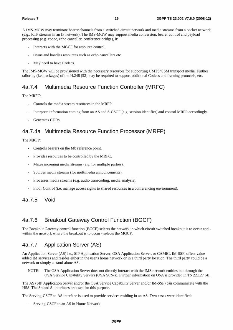
3GPP
3GPP TS 23.002 V7.6.0 (2008-12)29Release 7
A IMS-MGW may terminate bearer channels from a switched circuit network and media streams from a packet network (e.g., RTP streams in an IP network). The IMS-MGW may support media conversion, bearer control and payload processing (e.g. codec, echo canceller, conference bridge), it:
- Interacts with the MGCF for resource control.
- Owns and handles resources such as echo cancellers etc.
- May need to have Codecs.
The IMS-MGW will be provisioned with the necessary resources for supporting UMTS/GSM transport media. Further tailoring (i.e. packages) of the H.248 [52] may be required to support additional Codecs and framing protocols, etc.
4a.7.4 Multimedia Resource Function Controller (MRFC) The MRFC:
- Controls the media stream resources in the MRFP.
- Interprets information coming from an AS and S-CSCF (e.g. session identifier) and control MRFP accordingly.
- Generates CDRs .
4a.7.4a Multimedia Resource Function Processor (MRFP) The MRFP:
- Controls bearers on the Mb reference point.
- Provides resources to be controlled by the MRFC.
- Mixes incoming media streams (e.g. for multiple parties).
- Sources media streams (for multimedia announcements).
- Processes media streams (e.g. audio transcoding, media analysis).
- Floor Control (i.e. manage access rights to shared resources in a conferencing environment).
4a.7.5 Void
4a.7.6 Breakout Gateway Control Function (BGCF) The Breakout Gateway control function (BGCF) selects the network in which circuit switched breakout is to occur and - within the network where the breakout is to occur - selects the MGCF.
4a.7.7 Application Server (AS) An Application Server (AS) i.e., SIP Application Server, OSA Application Server, or CAMEL IM-SSF, offers value added IM services and resides either in the user's home network or in a third party location. The third party could be a network or simply a stand-alone AS.
NOTE: The OSA Application Server does not directly interact with the IMS network entities but through the OSA Service Capability Servers (OSA SCS-s). Further information on OSA is provided in TS 22.127 [4].
The AS (SIP Application Server and/or the OSA Service Capability Server and/or IM-SSF) can communicate with the HSS. The Sh and Si interfaces are used for this purpose.
The Serving-CSCF to AS interface is used to provide services residing in an AS. Two cases were identified:
- Serving-CSCF to an AS in Home Network.

3GPP
3GPP TS 23.002 V7.6.0 (2008-12)30Release 7
- Serving-CSCF to an AS in a trusted External Network (e.g., Third Party or Visited). The S-CSCF does not provide authentication and security functionality for secure direct third party access to the IM Subsystem. The OSA framework provides a standardized way for third party access to the IM Subsystem.
The Interrogating-CSCF to AS interface is used to forward SIP requests destined to a Public Service Identity hosted by the AS directly to that AS.
An Application Server may influence and impact the SIP session on behalf of the services supported by the operator's network. An AS may host and execute services.
4a.7.8 Interconnection Border Control Function (IBCF) An IBCF provides application specific functions at the SIP/SDP protocol layer in order to perform interconnection between two operator domains. It enables communication between IPv6 and IPv4 SIP applications. network topology hiding, controlling transport plane functions, screening of SIP signalling information, selecting the appropriate signalling interconnect and generation of charging data records. Details are described in TS 23.228 [34].
4a.7.9 Transition Gateway (TrGW) A TrGW is located within the media path and controlled by an IBCF. It provides functions like network address/port translation and IPv4/IPv6 protocol translation. Details are described in TS 23.228 [34].
4a.7.10 Location Retrieval Function (LRF) The LRF retrieves location information for the UE including, where required, interim location information, initial location and updated location information. The LRF may interact with a Routing Determination Function (RDF) in order to obtain routing information. The LRF may interact with a GMLC or other types of location server functions in order to obtain location information. Further definitions of the LRF is provided in TS 23.167 [74].
4a.8 Signalling Gateway Function (SGW) The SGW performs the signalling conversion (both ways) at transport level between the SS7 based transport of signalling used in pre-Rel-4 networks, and the IP based transport of signalling possibly used in post-R99 networks (i.e. between Sigtran SCTP/IP and SS7 MTP). The SGW does not interpret the application layer (e.g. MAP, CAP, BICC, ISUP) messages but may have to interpret the underlying SCCP or SCTP layer to ensure proper routing of the signalling.
4a.9 Global Text Telephony Specific entities Interworking between cellular text modem (CTM) and text telephony standards (e.g. V.18) used in external networks can be supported by three methods:
- Routing calls through a CTM Special resource function (CTM-SRF) in the core network. The CTM-SRF is linked in to the call path via CAMEL procedures. Depending on operator configuration the CTM-SRF may also be linked in to the call path for Emergency calls.
- A CTM / Text telephone converting function included along the speech call path selected by the network after an indication from the terminal that CTM is required.
- A CTM / Text telephone converting function included in all speech call paths.
Further information of the support for text telephony is found in TS 23.226 [37].
For further details of CTM, see TS 26.226 [38].
4a.10 Security Gateway (SEG) The UMTS network domain shall be logically and physically divided into security domains in order to protect IP based control plane signalling. These security domains typically coincide with operator borders.

3GPP
3GPP TS 23.002 V7.6.0 (2008-12)31Release 7
The interface between different security domains is protected by Security Gateways (SEGs). The SEGs are responsible for enforcing the security policy of a IP security domain towards other SEGs in the destination IP security domain. All NDS/IP traffic shall pass through a SEG before entering or leaving a security domain. For further details of SEG, see TS 33.210 [64].
4a.11 Application Function (AF) The Application Function (AF) is an element offering applications that require the control of IP bearer resources or the control of flow based bearer charging. The AF is capable of communicating with the PCRF to transfer dynamic QoS-related service information and/or dynamic charging-related service information.
One example of an AF is the P-CSCF of the IM CN subsystem.
4a.12 Void
4a.13 3GPP/WLAN Interworking entities
4a.13.1 WLAN UE A WLAN UE is the User Equipment using a UICC card utilized by a 3GPP subscriber to access the WLAN network for 3GPP interworking purpose.
4a.13.2 3GPP AAA Proxy The 3GPP AAA Proxy represents a AAA proxying and filtering function and resides in the visited 3GPP network. It is involved in access and service authentication and authorization procedures of a WLAN UE.
4a.13.3 3GPP AAA Server The 3GPP AAA server resides in the 3GPP network and is responsible for access and service authentication and authorization of a WLAN UE.
4a.13.4 WLAN Access Gateway (WAG) The WLAN access gateway is a gateway between WLAN and 3GPP network. In the roaming case it resides in the visited 3GPP network, otherwise in the home 3GPP network. It provides filtering, policing and charging functionality for the traffic between WLAN UE and 3GPP network.
4a.13.5 Packet Data Gateway (PDG) The Packet Data Gateway provides access to PS based services for a WLAN UE. It resides either in the home (for access to home services) or in the visited 3GPP network (for access to local services).
4a.14 Multimedia Broadcast Multicast Service (MBMS) specific entities
4a.14.1 General The Multimedia Broadcast Multicast Service (MBMS) is a point-to-multipoint service in which data is transmitted from a single source entity to multiple recipients. TS 23.246 [70] contains the technical realization of the service.

3GPP
3GPP TS 23.002 V7.6.0 (2008-12)32Release 7
4a.14.2 Broadcast-Multicast Service Centre (BM-SC) The Broadcast-Multicast Service Centre provides functions for MBMS user service provisioning and delivery. It may serve as an entry point for content provider MBMS transmissions, used to authorise and initiate MBMS Bearer Services within the PLMN and can be used to schedule and deliver MBMS transmissions.
4a.15 Void
4a.16 GUP Server The GUP Server is a functional entity providing a single point of access to the Generic User Profile data of a particular subscriber. The architecture does not specify or limit the physical location of the GUP Server enabling flexibility in the implementations. For further details of the GUP Server, see TS 23.240 [71].
4a.17 Policy and Charging Rules Function (PCRF) The Policy and Charging Rules Function (PCRF) acts as a policy decision point for policy and charging control of service data flows and IP bearer resources. The PCRF selects and provides the applicable policy and charging control decision to the PCEF.
4a.18 Policy and Charging Enforcement Function (PCEF) The Policy and Charging Enforcement Function (PCEF) acts as a policy enforcement point for policy and charging control of IP bearer resources.
This functional entity is located at the Gateway (e.g. GGSN in the GPRS case).
4a.19 Support of Short Message Service over generic 3GPP Internet Protocol access (SMSIP) specific entities
4a.19.1 General Support of Short Message Service over generic 3GPP Internet Protocol access (SMSIP) provide 3GPP SMS messaging services across any form of IP Connectivity Access Network. TS 23.204 [75] contains the technical realization of the service.
4a.19.2 IP-Short-Message-Gateway (IP-SM-GW) The IP Short Message Gateway function is used to deliver SMS messages over the IP network. The detailed function is described in TS 23.204 [75].
5 Configuration of a Public Land Mobile Network
5.1 Basic configuration The basic configuration of a Public Land Mobile Network (PLMN) supporting GPRS and the interconnection to the PSTN/ISDN and PDN is presented in figure 1 and figure 1a. This configuration presents signalling and user traffic interfaces which can be found in a PLMN. Implementations may be different: some particular functions may be gathered in the same equipment and then some interfaces may become internal interfaces.

3GPP
3GPP TS 23.002 V7.6.0 (2008-12)33Release 7
In the basic configuration presented in figure 1, all the functions are considered implemented in different equipments. Therefore, all the interfaces within PLMN are external. Interfaces A and Abis are defined in the 48-series of Technical Specifications. Interfaces Iu, Iur and Iub are defined in the 25.4xx-series of Technical Specifications. Interfaces B, C, D, E, F and G need the support of the Mobile Application Part of the signalling system No. 7 to exchange the data necessary to provide the mobile service. No protocols for the H-interface and for the I-interface are standardized. All the GPRS-specific interfaces (G- series) are defined in the 23-series and 24-series of Technical Specifications. Interfaces Mc, Nb, and Nc are defined in TS 23.205 [43] and in the 29-series of Technical Specifications.
From this configuration, all the possible PLMN organisations can be deduced. In the case when some functions are contained in the same equipment, the relevant interfaces become internal to that equipment.
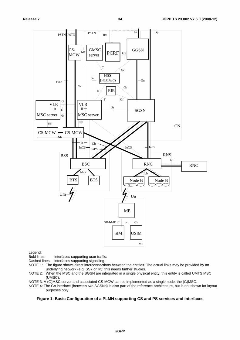
3GPP
3GPP TS 23.002 V7.6.0 (2008-12)34Release 7
BSS
BSC
RNS
RNC
CN
Node B Node B
IuCS IuPS
Iur
Iub
USIM
ME
MS
Cu
Uu
MSC server SGSN
Gs
GGSN GMSC server
Gn HSS (HLR,AuC)
Gr
GcC
D
E
EIR
F Gf
GiPSTN
IuCSIuPS
VLR B
Gp
VLR G
BTS BTS
Um
RNC Abis
SIM
SIM-ME i/f or
MSC server B
PSTN
cell
CS-MGW CS-MGW
CS-MGW
Nb
Mc Mc
Nb
PSTN PSTN
Nc
Mc
A Gb
Nc
PDFGo
GqGo*
CRFGx
Rx
PCRF
Legend: Bold lines: interfaces supporting user traffic; Dashed lines: interfaces supporting signalling. NOTE 1: The figure shows direct interconnections between the entities. The actual links may be provided by an
underlying network (e.g. SS7 or IP): this needs further studies. NOTE 2: When the MSC and the SGSN are integrated in a single physical entity, this entity is called UMTS MSC
(UMSC). NOTE 3: A (G)MSC server and associated CS-MGW can be implemented as a single node: the (G)MSC. NOTE 4: The Gn interface (between two SGSNs) is also part of the reference architecture, but is not shown for layout
purposes only.
Figure 1: Basic Configuration of a PLMN supporting CS and PS services and interfaces

3GPP
3GPP TS 23.002 V7.6.0 (2008-12)35Release 7
E Gd
SGSN
SMS-GMSC/ SMS-IWMSC
MSC-Server HSS
(HLR)
C
Figure 1a: Configuration for Short Message Service
5.2 Configuration of LCS entities
5.2.1 Configuration of LCS entities for GERAN The configuration of LCS entities for GERAN is presented in figure 2. In the figure, all the functions are considered implemented in different logical nodes. If two logical nodes are implemented in the same physical equipment, the relevant interfaces may become internal to that equipment.
Figure 2: Configuration of LCS entities for a GERAN PLMN
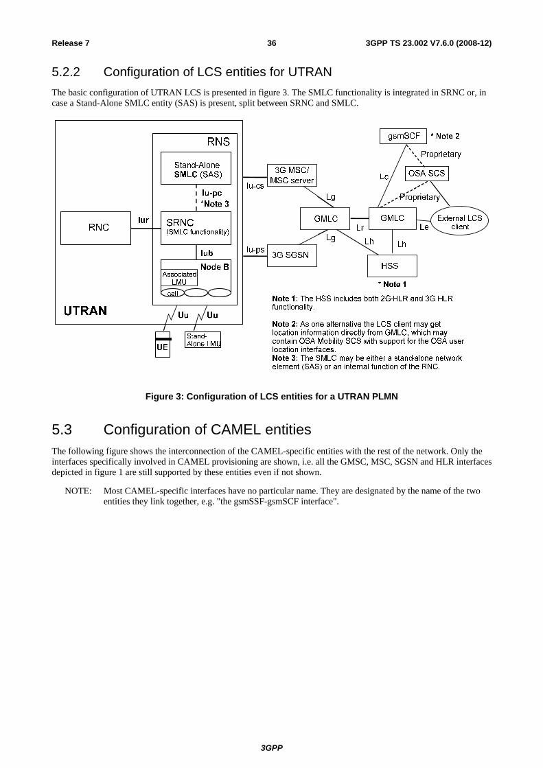
3GPP
3GPP TS 23.002 V7.6.0 (2008-12)36Release 7
5.2.2 Configuration of LCS entities for UTRAN The basic configuration of UTRAN LCS is presented in figure 3. The SMLC functionality is integrated in SRNC or, in case a Stand-Alone SMLC entity (SAS) is present, split between SRNC and SMLC.
Figure 3: Configuration of LCS entities for a UTRAN PLMN
5.3 Configuration of CAMEL entities The following figure shows the interconnection of the CAMEL-specific entities with the rest of the network. Only the interfaces specifically involved in CAMEL provisioning are shown, i.e. all the GMSC, MSC, SGSN and HLR interfaces depicted in figure 1 are still supported by these entities even if not shown.
NOTE: Most CAMEL-specific interfaces have no particular name. They are designated by the name of the two entities they link together, e.g. "the gsmSSF-gsmSCF interface".

3GPP
3GPP TS 23.002 V7.6.0 (2008-12)37Release 7
MSC
GMSC
HLR
C
D
VLRB
gsmSCF
gsmSSF
gsmSSF
gsmSRF
SGSN
gprsSSF
GrGe
Figure 4: configuration of CAMEL entities
The bold lines are used for interfaces supporting user data only, the dashed lines are used for interfaces supporting signalling only.
5.4 Configuration of CBS entities
Note 1: Interface outside the scope of 3GPP/GSM UE
IuBC
BSS
Abis
BSC
BTS BTS
RNS
Iub
RNC
Node B Node B
CN
Note 1
CBC
Figure 5: Configuration of a PLMN supporting Cell Broadcast Service entities
5.5 Configuration of IM CN Subsystem entities The configuration of IM CN Subsystem entities is presented in figure 6. In the figure, all the functions are considered implemented in different logical nodes. If two logical nodes are implemented in the same physical equipment, the relevant interfaces may become internal to that equipment.

3GPP
3GPP TS 23.002 V7.6.0 (2008-12)38Release 7
Only the interfaces specifically linked to the IM subsystem are shown, i.e. all the SGSN, GGSN and HSS interfaces depicted in figure 1 are still supported by these entities even if not shown.
E-CSCF
P-CSCF
IM Subsystem
CSCF MGCF
HSS Cx
IP Multimedia Networks
IMS-MGW
CS Network
Mn
Mb
Mg
Mm
MRFP
Mb
Mr
Mb
Legacy mobile signalling Networks
CSCF
Mw
Mw
Gm
BGCF Mj Mi
BGCF
Mk MkC, D, Gc, Gr
UE
Mb
Mb
Mb
MRFC
SLF
Dx
Mp
CS
CS
Rx
Mw
Mm
LRF
Ml
Le
BGCF
Mi
LCS Client
Legend: Bold lines: interfaces supporting user traffic; Dashed lines: interfaces supporting only signalling. NOTE: The reference point CS (Circuit Switched) is not specified in this specification.
Figure 6: Configuration of IM Subsystem entities
The figure below depicts an overall view of the functional architecture for services.

3GPP
3GPP TS 23.002 V7.6.0 (2008-12)39Release 7
S - CSCF S - CSCF
SIP Application Server
SIP Application Server
HSS HSS OSA service capability server
(SCS)
OSA service capability server
(SCS)
IM - SSF IM - SSF
Camel Service Environment
Camel Service Environment
OSA application
server
OSA application
server
ISC
Cx ISC
ISC
CAP MAP
OSA API
SCIM
AS AS
Sh
Si
Figure 6a: Functional architecture for the provision of service in the IMS
The purpose of the IM SSF is to host the CAMEL network features (i.e. trigger detection points, CAMEL Service Switching Finite State Machine, etc) and to interwork with CAP.
The IM SSF and the CAP interface support legacy services only.
The application server may contain "service capability interaction manager" (SCIM) functionality and other application servers. The SCIM functionality is an application which performs the role of interaction management. The internal components are represented by the "dotted boxes" inside the SIP application server. The internal structure of the application server is outside the standards. The Sh interface shall have sufficient functionality to enable this scenario.
The figure below depicts an overall view of the functional architecture for enabling the management of the user's service related information via the Ut interface.
UE S-CSCF
HSS ISC
Cx
SIPApplication
Server
Ut
Sh
Figure 6b: Functional architecture for the management of the user's service related information
The figure below depicts an overall view of the functional architecture for routing SIP requests between I-CSCF and Application Server.
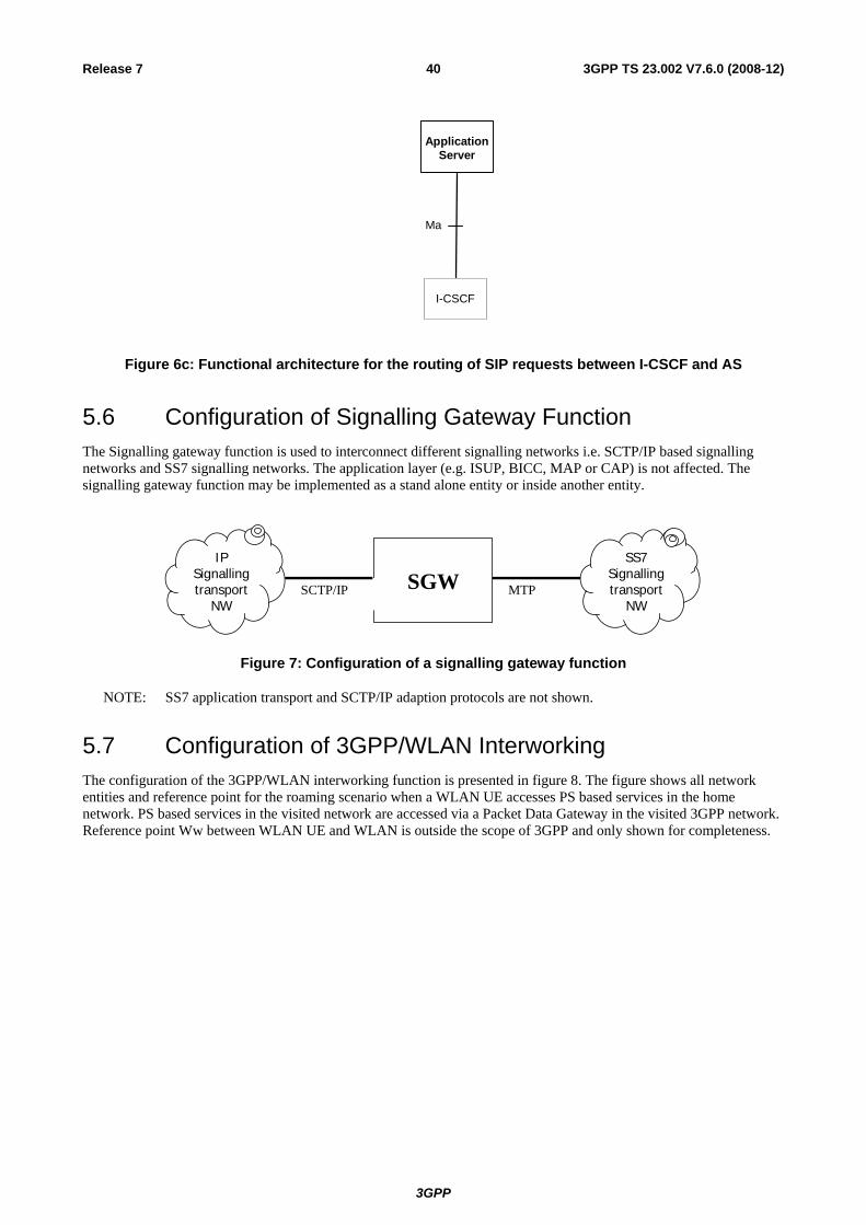
3GPP
3GPP TS 23.002 V7.6.0 (2008-12)40Release 7
I-CSCF
Application Server
Ma
Figure 6c: Functional architecture for the routing of SIP requests between I-CSCF and AS
5.6 Configuration of Signalling Gateway Function The Signalling gateway function is used to interconnect different signalling networks i.e. SCTP/IP based signalling networks and SS7 signalling networks. The application layer (e.g. ISUP, BICC, MAP or CAP) is not affected. The signalling gateway function may be implemented as a stand alone entity or inside another entity.
SGWSCTP/IP MTP
IPSignallingtransport
NW
SS7Signallingtransport
NW
Figure 7: Configuration of a signalling gateway function
NOTE: SS7 application transport and SCTP/IP adaption protocols are not shown.
5.7 Configuration of 3GPP/WLAN Interworking The configuration of the 3GPP/WLAN interworking function is presented in figure 8. The figure shows all network entities and reference point for the roaming scenario when a WLAN UE accesses PS based services in the home network. PS based services in the visited network are accessed via a Packet Data Gateway in the visited 3GPP network. Reference point Ww between WLAN UE and WLAN is outside the scope of 3GPP and only shown for completeness.
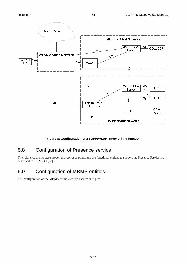
3GPP
3GPP TS 23.002 V7.6.0 (2008-12)41Release 7
Figure 8: Configuration of a 3GPP/WLAN interworking function
5.8 Configuration of Presence service The reference architecture model, the reference points and the functional entities to support the Presence Service are described in TS 23.141 [68].
5.9 Configuration of MBMS entities The configuration of the MBMS entities are represented in figure 9.

3GPP
3GPP TS 23.002 V7.6.0 (2008-12)42Release 7
UE SGSN
UE GERAN
UTRAN
HLR
GGSNTPF
BM - SC
ContentProvider /MulticastBroadcastSource
Uu Iu
Iu /Gb
Um
Gr
Gn /Gp
Gi
PDN(e .g . Internet )
OSASCS
Gmb
ContentProvider /MulticastBroadcastSource
Figure 9: Configuration of MBMS entities
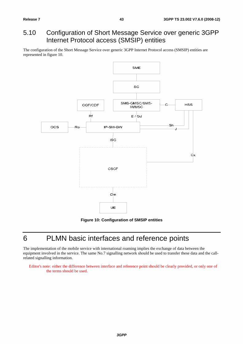
3GPP
3GPP TS 23.002 V7.6.0 (2008-12)43Release 7
5.10 Configuration of Short Message Service over generic 3GPP Internet Protocol access (SMSIP) entities
The configuration of the Short Message Service over generic 3GPP Internet Protocol access (SMSIP) entities are represented in figure 10.
Figure 10: Configuration of SMSIP entities
6 PLMN basic interfaces and reference points The implementation of the mobile service with international roaming implies the exchange of data between the equipment involved in the service. The same No.7 signalling network should be used to transfer these data and the call-related signalling information.
Editor's note: either the difference between interface and reference point should be clearly provided, or only one of the terms should be used.
3GPP
3GPP TS 23.002 V7.6.0 (2008-12)44Release 7
6.1 Interfaces between Mobile Station and the Fixed Infrastructure
6.1.1 Interface between Mobile Station and Base Station System (Um-interface)
The interface between the MS and the BSS is specified in the 44- and 45-series of Technical Specifications.
6.1.2 Interface between User Equipment and Radio Network System (Uu-interface)
The interface between the UE and the RNS is specified in the 24- and 25-series of Technical Specifications.
6.2 Interface between the Core Network and the Access Network
6.2.1 Interfaces between the CS domain and the Access Network
6.2.1.1 Interface between the MSC and Base Station System (A-interface)
The interface between the MSC and its BSS is specified in the 48-series of Technical Specifications.
The BSS-MSC interface is used to carry information concerning:
- BSS management;
- call handling;
- mobility management.
6.2.1.2 Interface between the MSC and Base Station System (Iu_CS interface)
The interface between the MSC and its BSS is specified in the 25.41x-series of Technical Specifications.
The BSS-MSC interface is used to carry information concerning:
- BSS management;
- call handling;
- mobility management;
6.2.1.3 Interface between the MSC and RNS (Iu_CS interface)
The interface between the MSC and its RNS is specified in the 25.41x-series of Technical Specifications.
The RNS-MSC interface is used to carry information concerning:
- RNS management;
- call handling;
- mobility management.

3GPP
3GPP TS 23.002 V7.6.0 (2008-12)45Release 7
6.2.2 Interfaces between the PS domain and the Access Network
6.2.2.1 Interface between SGSN and BSS (Gb-interface)
The BSS-SGSN interface is used to carry information concerning:
- packet data transmission;
- mobility management.
The Gb interface is defined in TS 48.014 [44], TS 48.016 [45] and TS 48.018 [46].
6.2.2.2 Interface between SGSN and BSS (Iu_PS-interface)
The BSS-SGSN interface is used to carry information concerning:
- packet data transmission;
- mobility management.
The Iu_PS interface is defined in the 25.41x-series of 3GPP Technical Specifications.
6.2.2.3 Interface between SGSN and RNS (Iu_PS-interface)
The RNS-SGSN interface is used to carry information concerning:
- packet data transmission;
- mobility management.
The Iu_PS interface is defined in the 25.41x-series of Technical Specifications.
6.3 Interfaces internal to the Access Network
6.3.1 Interface between BSC and BTS (Abis-interface) When the BSS consists of a Base Station Controller (BSC) and one or more Base Transceiver Stations (BTS), this interface is used between the BSC and BTS to support the services offered to the GSM users and subscribers.
The interface also allows control of the radio equipment and radio frequency allocation in the BTS.
The interface is specified in the 48.5x-series of Technical Specifications.
6.3.2 Interface between RNC and Node B (Iub-interface) When the RNS consists of a Radio Network Controller (RNC) and one or more Node B, this interface is used between the RNC and Node B to support the services offered to the UMTS users and subscribers.
The interface also allows control of the radio equipment and radio frequency allocation in the Node B.
The interface is specified in the 25.43x series of Technical Specifications.
6.3.3 Interface between two RNCs (Iur-interface) This interface is defined in the 25.42x series of Technical Specifications.

3GPP
3GPP TS 23.002 V7.6.0 (2008-12)46Release 7
6.4 Interfaces internal to the Core Network
6.4.1 Interfaces internal to the CS domain
6.4.1.1 Interface between the MSC server and its associated VLR (B-interface)
The VLR is the location and management database for the mobile subscribers roaming in the area controlled by the associated MSC server(s). Whenever the MSC server needs data related to a given mobile station currently located in its area, it interrogates the VLR. When a mobile station initiates a location updating procedure with an MSC server, the MSC server informs its VLR which stores the relevant information. This procedure occurs whenever an MS roams to another location area. Also, when a subscriber activates a specific supplementary service or modifies some data attached to a service, the MSC server informs (via the VLR) the HLR which stores these modifications and updates the VLR if required.
This interface is internal to the MSC server /VLR; signalling on it is not standardised.
6.4.1.2 Interface between the HLR and the MSC server (C-interface)
The Gateway MSC server must interrogate the HLR of the required subscriber to obtain routing information for a call or a short message directed to that subscriber.
Signalling on this interface uses the Mobile Application Part (MAP), which in turn uses the services of Transaction Capabilities (see TS 29.002 [26]).
For CAMEL purposes, this interface is used as described in TS 23.078 [10c]. It is used e.g. at terminating calls to exchange routeing information, subscriber status, location information, subscription information, etc.
6.4.1.3 Interface between the HLR and the VLR (D-interface)
This interface is used to exchange the data related to the location of the mobile station and to the management of the subscriber. The main service provided to the mobile subscriber is the capability to set up or to receive calls within the whole service area. To support this, the location registers have to exchange data. The VLR informs the HLR of the location of a mobile station managed by the latter and provides it (either at location updating or at call set-up) with the roaming number of that station. The HLR sends to the VLR all the data needed to support the service to the mobile subscriber. The HLR then instructs the previous VLR to cancel the location registration of this subscriber. Exchanges of data may occur when the mobile subscriber requires a particular service, when he wants to change some data attached to his subscription or when some parameters of the subscription are modified by administrative means.
Signalling on this interface uses the Mobile Application Part (MAP), which in turn uses the services of Transaction Capabilities (see TS 29.002 [26]).
For CAMEL purposes, this interface is used to send the CAMEL related subscriber data to the visited PLMN and for provision of MSRN. The interface is also used for the other purposes described in TS 23.078 [10c], e.g. to retrieve subscriber status and location information of the mobile subscriber or to indicate suppression of announcement for a CAMEL service.
6.4.1.4 Interface between MSC servers or MSC server and IP-SM-GW (E-interface)
Between MSC server and IP-SM-GW only a subset of E interface functions is used.
When a mobile station moves from one MSC area to another during a call, a handover procedure has to be performed in order to continue the communication. For that purpose the MSC servers have to exchange data to initiate and then to realise the operation.
After the handover operation has been completed, the MSC servers will exchange information to transfer A- or Iu- interface signalling as defined in TS 23.009 [6].
When a short message is to be transferred between a Mobile Station and Short Message Service Centre (SC), in either direction, this interface is used to transfer the message between the MSC server serving the Mobile Station and the MSC server which acts as the interface to the SC or between the IP-SM-GW serving the Mobile Station has registered on it and the MSC server which acts as the interface to the SC.
3GPP
3GPP TS 23.002 V7.6.0 (2008-12)47Release 7
Signalling on this interface uses the Mobile Application Part (MAP), which in turn uses the services of Transaction Capabilities (see TS 29.002 [26]).
6.4.1.5 Interface between MSC server and EIR (F-interface)
This interface is used between MSC server and EIR to exchange data, in order that the EIR can verify the status of the IMEI retrieved from the Mobile Station.
Signalling on this interface uses the Mobile Application Part (MAP), which in turn uses the services of Transaction Capabilities (see TS 29.002 [26]).
6.4.1.6 Interface between VLRs (G-interface)
When a mobile subscriber moves from a VLR area to another Location Registration procedure will happen. This procedure may include the retrieval of the IMSI and authentication parameters from the old VLR.
Signalling on this interface uses the Mobile Application Part (MAP), which in turn uses the services of Transaction Capabilities (see TS 29.002 [26]).
6.4.1.7 Reference point (G)MSC server – CS-MGW (Mc Reference Point)
The Mc reference point describes the interfaces between the MSC Server and CS-MGW, and between the GMSC Server and CS-MGW. It has the following properties:
- full compliance with the H.248 [52] standard, baseline work of which is currently carried out in ITU-T Study Group 16, in conjunction with IETF MEGACO WG.
- flexible connection handling which allows support of different call models and different media processing purposes not restricted to H.323 [54] usage.
- open architecture where extensions/Packages definition work on the interface may be carried out.
- dynamic sharing of MGW physical node resources. A physical MGW can be partitioned into logically separate virtual MGWs/domains consisting of a set of statically allocated Terminations.
- dynamic sharing of transmission resources between the domains as the MGW controls bearers and manage resources according to the H.248 [52] protocols.
The functionality across the Mc reference point will need to support mobile specific functions such as SRNS relocation/handover and anchoring. It is expected that current H.248/IETF Megaco [52] standard mechanisms can be applied to enable this.
6.4.1.8 Reference Point MSC Server – GMSC Server (Nc Reference Point)
Over the Nc reference point, the Network-Network based call control is performed. Examples of this are ISUP or an evolvement of ISUP for bearer independent call control (BICC). Different options for signalling transport on Nc shall be possible including IP.
6.4.1.9 Reference Point CS-MGW – CS-MGW (Nb Reference Point)
Over the Nb reference point the bearer control and transport are performed. The transport may be RTP/UDP/IP [59], [60] or AAL2 (I.363-2) [57] for transport of user data. Different options for user data transport and bearer control shall be possible on Nb, for example: AAL2/Q.AAL2, STM/none, RTP/H.245 [58], IPBC.
6.4.2 Interfaces internal to the PS domain
6.4.2.1 Interface between SGSN and HLR (Gr-interface)
This interface is used to exchange the data related to the location of the mobile station and to the management of the subscriber. The main service provided to the mobile subscriber is the capability to transfer packet data within the whole service area. The SGSN informs the HLR of the location of a mobile station managed by the latter. The HLR sends to
3GPP
3GPP TS 23.002 V7.6.0 (2008-12)48Release 7
the SGSN all the data needed to support the service to the mobile subscriber. Exchanges of data may occur when the mobile subscriber requires a particular service, when he wants to change some data attached to his subscription or when some parameters of the subscription are modified by administrative means.
Signalling on this interface uses the Mobile Application Part (MAP), which in turn uses the services of Transaction Capabilities (TCAP) (see TS 29.002 [26]).
6.4.2.2 Interface between SGSN and GGSN (Gn- and Gp-interface)
These interfaces are used to support mobility between the SGSN and GGSN. The Gn interface is used when GGSN and SGSN are located inside one PLMN. The Gp-interface is used if GGSN and SGSN are located in different PLMNs. The Gn/Gp interface also includes a part which allows SGSNs to communicate subscriber and user data, when changing SGSN.
Signalling on this interface uses the User Datagram Protocol, UDP/IP [59]. The Gn/Gp interface is defined in TS 29.060 [51].
6.4.2.3 Signalling Path between GGSN and HLR (Gc-interface)
This optional signalling path may be used by the GGSN to retrieve information about the location and supported services for the mobile subscriber, to be able to activate a packet data network address.
There are two alternative ways to implement this signalling path:
- if an SS7 interface is implemented in the GGSN, signalling between the GGSN and the HLR uses the Mobile Application Part (MAP), which in turn uses the services of Transaction Capabilities (TCAP) (see TS 29.002 [26]);
- if there is no SS7 interface in the GGSN, any GSN in the same PLMN and which has an SS7 interface installed can be used as a GTP to MAP protocol converter, thus forming a signalling path between the GGSN and the HLR.
6.4.2.4 Interface between SGSN and EIR (Gf-interface)
This interface is used between SGSN and EIR to exchange data, in order that the EIR can verify the status of the IMEI retrieved from the Mobile Station.
Signalling on this interface uses the Mobile Application Part (MAP), which in turn uses the services of Transaction Capabilities (TCAP) (see TS 29.002 [26]).
6.4.3 Interfaces used by CS and PS domains
6.4.3.1 Interface between MSC/VLR and SGSN (Gs-interface)
The SGSN may send location information to the MSC/VLR via the optional Gs interface. The SGSN may receive paging requests from the MSC/VLR via the Gs interface. The MSC/VLR may indicate to an SGSN, via the Gs interface, that an MS is engaged in a service handled by the MSC.
Signalling on this interface uses connectionless SCCP (without TCAP). SCCP Global Title (GT) is used for addressing. The Gs-interface is defined in TS 29.016 [48] and TS 29.018 [49].
6.4.3.2 Interface between HLR and AuC (H-Interface)
When an HLR receives a request for authentication and ciphering data for a Mobile Subscriber and it does not hold the requested data, the HLR requests the data from the AuC. The protocol used to transfer the data over this interface is not standardised.
3GPP
3GPP TS 23.002 V7.6.0 (2008-12)49Release 7
6.4.3.3 Interface between SGSN/IP-SM-GW and SMS-GMSC/SMS-IWMSC (Gd-Interface)
This interface is used to transfer short messages between SGSN/IP-SM-GW and SMS-GMSC or SMS-IWMSC over GPRS. Signalling on this interface uses the Mobile Application Part (MAP) (see TS 29.002 [26]).
6a PLMN specific interfaces
6a.1 GCR-specific interface
6a.1.1 Interface between the MSC and its associated GCR (I-interface) The GCR is the management data base for the voice group or broadcast calls in the area controlled by the associated MSC(s). Whenever the MSC needs data related to a requested voice group or broadcast call it interrogates the GCR to obtain the respective voice group or broadcast call attributes. The protocol used to transfer the data over this interface is not standardized.
6a.2 Void
6a.3 LCS-specific interfaces
6a.3.1 LCS interfaces using MAP The following interfaces are based on MAP in LCS.
- Lh interface: interface between GMLC and HLR. This interface is used by the GMLC to request the address of the visited MSC or SGSN for a particular target UE whose location has been requested (see TS 29.002 [26]).
- Lg interface: interface between GMLC - MSC and GMLC - SGSN. This interface is used by the GMLC to convey a location request to the MSC or SGSN currently serving a particular target UE whose location was requested. The interface is used by the MSC or SGSN to return location results to the GMLC (see TS 29.002 [26]).
- Lc interface: between GMLC and gsmSCF, CAMEL. This interface is used to get location information for CAMEL based services. (see TS 29.002 [26]).
6a.3.2 Void
6a.3.3 Void
6a.3.4 Void
6a.3.5 Interface between BSC and SMLC (Lb-interface) In GERAN, a SMLC supports positioning via signalling on the Lb interface to the BSC serving the target MS.

3GPP
3GPP TS 23.002 V7.6.0 (2008-12)50Release 7
Signalling on this interface uses BSSAP-LE, which is specified in TS 49.031 [50]
In UTRAN, the Lb interface is not standardized, the SMLC functionality is included in SRNC.
6a.3.6 Interface between Peer SMLCs (Lp-interface) In GERAN, a SMLC may support the Lp interface to enable access to information and resources owned by another SMLC.
Signalling on this interface uses BSSAPP-LE, which is defined in TS 49.031 [50], and SMLCPP, which is specified in TS 48.031 [47].
In UTRAN, the SMLC functionality is included in SRNC and the Iur interface shall include the Lp interface type of functionality.
6a.3.7 Interface between BTS and LMU (Um-interface) The Um/Uu interface specific to LCS is defined in TS 44.071 [55].
6a.3.8 Interface between GMLC and External LCS Client (Le-interface) The Le interface is used by the external LCS client to retrieve location information from the LCS server. Signalling on this interface may use the OMA Mobile Location Protocol (MLP) [62] and Open Service Access Application Programming Interface (OSA-API) [63].
6a.3.9 Interface between RNS and Stand-Alone LMU, UE (Uu-interface) The Uu interface is used to communicate among the UE Positioning entities associated with the SRNC, the UEs and the stand-alone LMU. The Uu interface may pass measurement requests and results to and from the UE or the stand-alone LMU. UE Positioning operations at the Uu interface are generally defined in the 24- and 25-series of 3GPP Technical Specifications. Furthermore, 25.305 describes how a stand-alone LMU may be distinguished from a normal UE.
6a.3.10 Interface between SRNC and SAS (Stand-Alone SMLC) (Iupc-interface)
The Iupc interface defined for LCS is specified in TS 25.453 [66].
6a.3.11 Interface between GMLC and GMLC (Lr-interface) The Lr interface is used by the GMLC to communicate with other GMLCs. Signalling on this interface may use the OMA Roaming Location Protocol (RLP) [69].
6a.4 CAMEL-specific interfaces The CAMEL-specific interfaces are detailed in TS 23.078 [10c]. These interfaces are.
6a.4.1 GMSC - gsmSSF interface
This is an internal interface. The interface is described in the specification to make it easier to understand the handling of Detection Points (arming/disarming of DPs, DP processing etc.).
6a.4.2 gsmSSF - gsmSCF interface
This interface is used by the gsmSCF to control a call in a certain gsmSSF and to request the gsmSSF to establish a connection with a gsmSRF. Relationships on this interface are opened as a result of the gsmSSF sending a request for instructions to the gsmSCF.

3GPP
3GPP TS 23.002 V7.6.0 (2008-12)51Release 7
6a.4.3 MSC - gsmSSF interface
This is an internal interface. The interface is described in the specification to make it easier to understand the handling of DPs (arming/disarming of DPs, DP processing etc.).
6a.4.4 gsmSCF - HLR interface
This interface is used by the gsmSCF to request information from the HLR. As a network operator option the HLR may refuse to provide the information requested by the gsmSCF.
This interface is also used for USSD operations, both for gsmSCF-initiated dialogues and MS-initiated dialogues (relayed via HLR). It is a network operator option whether to support or not USSD operations on this interface.
6a.4.5 gsmSCF - gsmSRF interface
This interface is used by the gsmSCF to instruct the gsmSRF to play tones/announcements to the users.
6a.4.6 MSC - gsmSCF interface
This interface is used by the MSC to send supplementary service invocation notifications to the gsmSCF.
6a.4.7 SGSN - gprsSSF interface
This is an internal interface. The interface is described in the specification to make it easier to understand the handling of DPs (arming/disarming of DPs, DP processing etc.).
6a.4.8 gprsSSF - gsmSCF interface (Ge Reference Point)
This interface is used by the gsmSCF to control a GPRS session or individual PDP Context in a certain gprsSSF. Relationships between the gprsSSF and the gsmSCF (GPRS dialogues) on this interface are opened as a result of the gprsSSF sending a request for instructions to the gsmSCF. This interface is also known as Ge reference point [9a].
6a.5 CBS-specific interfaces
6a.5.1 Interface between the CBC and RNS (Iu_BC Interface) The interface between the CBC and the RNS is specified in the 25.41x-series of Technical Specifications.
The CBC-RNS interface is used to carry information concerning:
- the CBS messages itself; and
- CBS delivery parameter.

3GPP
3GPP TS 23.002 V7.6.0 (2008-12)52Release 7
6a.6 Number portability specific interfaces
6a.6.1 IN-based solution
6a.6.1.1 NPDB to MSC interface
Upon receiving an ISUP IAM, the (gateway or visited) MSC send a database query to the NPDB as a result of analysis of the received MSISDN. The MSISDN is included in the query to the NPDB. The NPDB determines whether the MSISDN is ported or not. If not, it responds back to the MSC to continue the normal call setup procedure for MT calls (optionally providing the Routing Number). If it is ported, the NPDB responds back to the MSC with a Routing Number pointing out the Subscription network.
6a.6.2 Signalling Relay-based solution
6a.6.2.1 GMSC to MNP-SRF interface
Upon receiving an ISUP IAM, the gateway MSC sends a routing interrogation to the MNP-SRF, which in turn will perform one of the actions, described in clause 4a.7, depending on the portability status of the subscriber and the network configuration (see TS 23.066 [40]).
6a.6.2.2 MNP-SRF to HLR interface
When the MNP-SRF receives a routing interrogation from the GMSC or an interrogating network entity (non/call related signalling), and it determines that the subscriber is not ported or it has been ported from another network, the MNP-SRF relays the message to the HLR.
6a.7 IM Subsystem Reference Points
6a.7.1 Reference Point HSS - CSCF (Cx Reference Point) The Cx reference point supports information transfer between CSCF and HSS.
The main procedures that require information transfer between CSCF and HSS are
1) Procedures related to Serving CSCF assignment
2) Procedures related to routing information retrieval from HSS to CSCF
3) Procedures related to authorisation (e.g., checking of roaming agreement)
4) Procedures related to authentication: transfer of security parameters of the subscriber between HSS and CSCF
5) Procedures related to filter control: transfer of filter parameters of the subscriber from HSS to CSCF
Further information on the Cx reference point is provided in TS 23.228 [34].
6a.7.2 Reference Point CSCF – UE (Gm Reference Point) The Gm reference point supports the communication between UE and IM CN subsystem, e.g. related to registration and session control.
The protocol used for the Gm reference point is SIP (as defined by RFC 3261 [61], other relevant RFC's, and additional enhancements introduced to support 3GPP´s needs).
6a.7.3 Reference Point MGCF – IMS-MGW (Mn Reference Point) The Mn reference point describes the interfaces between the MGCF and IMS-MGW in the IMS. It has the following properties:

3GPP
3GPP TS 23.002 V7.6.0 (2008-12)53Release 7
- full compliance with the H.248 standard functions for IMS – PSTN/PLMN interworking.- flexible connection handling which allows support of different call models and different media processing purposes not restricted to H.323 [54] usage.
- open architecture where extensions/Packages definition work on the interface may be carried out.
- dynamic sharing of IMS-MGW physical node resources. A physical IMS-MGW can be partitioned into logically separate virtual MGWs/domains consisting of a set of statically allocated Terminations.
- dynamic sharing of transmission resources between the domains as the IMS- MGW controls bearers and manage resources according to the H.248 [52] protocols and functions for IMS.
6a.7.4 Reference Point MGCF – CSCF (Mg Reference Point) The Mg reference point allows the MGCF to forward incoming session signalling (from the circuit switched network) to the CSCF for the purpose of interworking with circuit switched networks.
The protocol used for the Mg reference point is SIP (as defined by RFC 3261 [61], other relevant RFC's, and additional enhancements introduced to support 3GPP´s needs).
6a.7.5 Void
6a.7.6 Reference Point CSCF - MRFC (Mr Reference Point) The Mr reference point allows interaction between an S-CSCF and an MRFC.
The protocol used for the Mr reference point is SIP (as defined by RFC 3261 [61], other relevant RFC's, and additional enhancements introduced to support 3GPP´s needs).
6a.7.6a Reference Point MRFC – MRFP (Mp Reference Point) The Mp reference point allows an MRFC to control media stream resources provided by an MRF.
The Mp reference point has the following properties:
- Full compliance with the H.248 [52] standard.
- Open architecture where extensions (packages) definition work on the interface may be carried out.
6a.7.7 Reference Point CSCF – CSCF (Mw Reference Point) The Mw reference point allows the communication and forwarding of signalling messaging between CSCFs, e.g. during registration and session control.
6a.7.8 Void
6a.7.9 Void
6a.7.10 Reference Point CSCF – BGCF (Mi reference point) This reference point allows the Serving CSCF to forward the session signalling to the Breakout Gateway Control Function for the purpose of interworking to the circuit switched networks.
The Mi reference point is based on external specifications i.e. SIP [61].
3GPP
3GPP TS 23.002 V7.6.0 (2008-12)54Release 7
6a.7.11 Reference Point BGCF – MGCF (Mj reference point) This reference point allows the Breakout Gateway Control Function to forward the session signalling to the Media Gateway Control Function for the purpose of interworking to the circuit switched networks.
The Mj reference point is based on external specifications i.e. SIP [61].
6a.7.12 Reference Point BGCF/IBCF – BGCF (Mk reference point) This reference point allows the Breakout Gateway Control Function/IBCF to forward the session signalling to another Breakout Gateway Control Function.
The Mk reference point is based on external specifications i.e. SIP [61].
6a.7.13 Reference Point CSCF- SLF (Dx Reference Point) This interface between CSCF and SLF is used to retrieve the address of the HSS which holds the subscription for a given user.
This interface is not required in a single HSS environment. An example for a single HSS environment is a server farm architecture.
Details are described in TS 23.228 [34], clause 5.8.1.
6a.7.14 Reference Point to IPv6 network services (Mb reference point) Via the Mb reference point IPv6 network services are accessed. These IPv6 network services are used for user data transport. Note, that GPRS provides IPv6 network services to the UE, i.e. the GPRS Gi reference point and the IMS Mb reference point may be the same.
6a.7.15 Reference Point S-CSCF – AS (ISC Reference Point) This interface between Serving CSCF and the Application Servers (i.e., SIP Application Server, OSA Service Capability Server, or CAMEL IM-SSF) is used to provide services for the IMS.
Details are described in TS 23.228 [34], clause 4.2.4.
6a.7.16 Reference Point HSS – SIP AS or OSA SCS (Sh Reference Point) The Application Server (SIP Application Server and/or the OSA Service Capability Server) may communicate to the HSS. The Sh interface is used for this purpose. Details are described in TS 23.228 [34], clause 4.2.4.
This reference point is also used to exchange signalling between IP-SM-GW and the HSS for SMSIP delivery.
6a.7.17 Reference Point HSS – CAMEL IM-SSF (Si Reference Point) The CAMEL Application Server (IM-SSF) may communicate to the HSS. The Si interface is used for this purpose. Details are described in TS 23.228 [34], clause 4.2.4.
6a.7.18 Reference Point UE – AS (Ut Reference Point) The Ut interface resides between the UE and the SIP Application Server.
The Ut interface enables the user to manage information related to his services. Such as creation and assignment of Public Service Identities, management of authorization policies that are used e.g. by Presence service, conference policy management, etc.
The AS may need to exhibit security related functions for the Ut interface, the details of these security functions are described in TS 33.222 [72].
3GPP
3GPP TS 23.002 V7.6.0 (2008-12)55Release 7
For the protocol at the Ut reference point HTTP shall be supported.
6a.7.19 Reference Point AS- SLF (Dh Reference Point) This interface between AS and SLF is used to retrieve the address of the HSS which holds the subscription for a given user.
This interface is not required in a single HSS environment. An example for a single HSS environment is a server farm architecture.
Details are described in TS 23.228 [34], clause 5.8.1.
6a.7.20 Reference Point CSCF/BGCF - IBCF (Mx Reference Point) The Mx reference point allows the communication and forwarding of signalling messages between a CSCF/BGCF and an IBCF, e.g. during session establishment.
6a.7.21 Reference Point IBCF - TrGW (Ix Reference Point) This interface is used by the IBCF to control the TrGW, e.g. to request network address translation binding.
6a.7.22 Reference Point I-CSCF – AS (Ma Reference Point) This interface between Interrogating-CSCF and the Application Servers (i.e. SIP Application Server, OSA Service Capability Server, or CAMEL IM-SSF) is used to:
- forward SIP requests destined to a Public Service Identity hosted by an Application Server directly to the Application Server. Details are described in TS 23.228 [34], clause 5.4.12; and
- initiate a request on behalf of a user or Public Service Identity, if the AS has no knowledge of the serving S-CSCF for that user or Public Service Identity. Details are described in TS 23.228 [34], clause 5.6.5.3.
6a.7.23 Reference Point P-CSCF – IMS Access Gateway (Iq Reference Point)
The Iq reference point is between the Proxy-CSCF and the IMS Access Gateway. It conveys the necessary information that is needed to allocate and release transport addresses.
Details are described in TS 23.228 [34], Annex G.
6a.7.23a Reference Point E-CSCF – LRF (Ml Reference Point) The Ml reference point allows the E-CSCF to request the LRF to validate the location information received from the UE, to determine or query the LRF for routing information to emergency centres. Location information may be received from LRF and/or reference key to allow the PSAP to retrieve location at a later stage.
6a.8 Void
6a.9 Reference Points for 3GPP/WLAN Interworking
6a.9.1 Reference point 3GPP AAA Server - HLR (D'/Gr' Reference Point) This is the reference point between the 3GPP AAA server and the HLR up to and including Rel-4 and the HSS in Rel-5. The functionality of this reference point is similar to that of the Wx reference point. For more information see TS 23.234 [67].
3GPP
3GPP TS 23.002 V7.6.0 (2008-12)56Release 7
6a.9.2 Reference point WLAN access network - 3GPP AAA Proxy/Server (Wa Reference Point)
This is the reference point between the WLAN access network and 3GPP AAA Proxy or Server. The AAA protocol on this reference point is used to transport authentication, authorization and charging data.
6a.9.3 Reference point 3GPP AAA Server – 3GPP AAA Proxy (Wd Reference Point)
This is the reference point between the 3GPP AAA Server and Proxy. the purpose of the protocols crossing this reference point is to transport authentication, authorization and related information. For more information see TS 23.234 [67].
6a.9.4 Reference point 3GPP AAA Server/Proxy - WAG (Wg Reference Point)
This is the reference point between the 3GPP AAA server/proxy and WAG. It is used to provide information needed by the WAG to perform policy enforcement functions for authorised users and to transport per-tunnel based charging information from the WAG to the AAA Proxy in roaming scenarios.
6a.9.5 Reference point PDG - packet data networks (Wi Reference Point) This is the reference point between the PDG and a packet data network. It may be an operator external public or private packet data network or an intra operator packet data network, e.g. for provision of IMS services.
6a.9.6 Reference Point 3GPP AAA Server/Proxy - PDG (Wm Reference Point)
This is the reference point between the 3GPP AAA server/proxy and PDG. The functionality of this reference point is to enable:
- The 3GPP AAA Server/Proxy to retrieve tunnelling attributes and WLAN UE's IP configuration parameters from/via Packet Data Gateway
- Carrying messages for service authentication and authorization
- Carrying authentication data for the purpose of tunnel establishment, tunnel data authentication and encryption.
For more information see TS 23.234 [67].
6a.9.7 Reference Point WAG - WLAN access network (Wn Reference Point)
This is the reference point between the WAG and the WLAN access network. It is used to force traffic between a WLAN UE and PDG to go through the WAG.
6a.9.8 Reference Point WAG - PDG (Wp Reference Point) This is the reference point between WAG and PDG. It is used to transport the Wu reference point protocol data packets.
6a.9.9 Reference point WLAN UE - PDG (Wu Reference Point) This is the reference point between the 3GPP WLAN UE and PDG. The functionality of this reference point is to establish a tunnel between WLAN UE and PDG and to exchange data packets between WLAN UE and PDG.

3GPP
3GPP TS 23.002 V7.6.0 (2008-12)57Release 7
6a.9.10 Reference point WLAN UE - WLAN access network (Ww Reference Point)
This is the reference point between the 3GPP WLAN UE and WLAN access network. The functionality of this reference point is specified by IEEE and outside the scope of 3GPP.
6a.9.11 Reference point 3GPP AAA Server - HSS (Wx Reference Point) This is the reference point between the 3GPP AAA server and HSS. The functionality of this reference point is to enable:
- Retrieval of authentication vectors
- Retrieval of WLAN access-related subscriber information (profile)
- Registration of the 3GPP AAA Server of an authorised WLAN user in the HSS
- Indication of change of subscriber profile
- Retrieval of online charging / offline charging function addresses from HSS.
- Retrieval of service related information
For more information see TS 23.234 [67].
6a.9.12 Reference point 3GPP AAA Server - SLF (Dw reference point) This reference point is between the 3GPP AAA Server and the SLF. The prime purpose of the protocol(s) crossing this reference point is to enable the 3GPP AAA Server to find the address of the HSS which holds the subscriber data for a given user identity in a configuration with multiple separately addressable HSSs.
6a.10 MBMS specific reference points
6a.10.1 Reference point GGSN – BM-SC (Gmb Reference Point) This reference point is used to exchange signalling between GGSN and BM-SC. This represents the network side boundary of the MBMS Bearer Service from a control plane perspective. This includes user specific Gmb signalling and MBMS bearer service specific signalling. The details for this reference point are described in TS 23.246 [70].
6a.11 Void
6a.12 Reference Points for 3GPP Generic User Profile (GUP)
6a.12.1 Reference Point GUP Server – Applications (Rg Reference Point) The Rg reference point resides between the GUP Server and the Applications.
The Rg reference point allows applications to create, read, modify and delete any user profile data using the harmonized access interface. The GUP Server locates the data repositories responsible of the storage of the requested profile component(s).
The details of the Rg reference point are described in TS 23.240 [71].
3GPP
3GPP TS 23.002 V7.6.0 (2008-12)58Release 7
6a.12.2 Reference Point GUP Server – HSS and Applications – HSS (Rp Reference Point)
The Rp reference point resides between the GUP Server and the HSS, and between the Applications and the HSS.
The Rp reference point enables the GUP Server and the Applications to access GUP Data Repositories. The HSS is one of the GUP Data Repositories. It stores the IM CN Subsystem user related data.
The details of the Rp reference point are described in TS 23.240 [71].
6a.13 Reference Points for Policy and Charging Control
6a.13.1 Reference Point PCEF - PCRF (Gx Reference Point) This interface allows the Policy and Charging Rules Function (PCRF) to control the Policy and Charging Control functionality for service data flow and IP bearer resources in the PCEF. For more information see TS 23.203 [73].
6a.13.2 Reference Point PCRF - Application Function (Rx Reference Point) This interface allows for dynamic QoS and charging-related service information to be exchanged between the Policy and Charging Rules Function (PCRF) and the Application Function (AF). This information is used by the PCRF for the control of service data flows and IP bearer resources. For more information see TS 23.203 [73].
6a.14 SMSIP specific reference points
6a.14.1 Reference point IP-SM-GW – HSS (J Reference Point) This reference point is used to exchange signalling between IP-SM-GW and the HSS for SMSIP delivery. The details for this reference point are described in TS 23.204 [75].
7 Reference points between the PLMN and other networks
The reference points between the PLMN and other networks, including dedicated networks, are described in the 49-series of Technical Specifications and in the 29-series of Technical Specifications.
7.1 Reference point fixed networks - MSC The MSC is based on a normal ISDN exchange. It has, for call control, the same reference points as the fixed network exchanges. The signalling reference point considered in the Technical Specifications is related to the signalling system No. 7 User Parts TUP and ISUP associated to the circuits used for incoming and outgoing calls.
7.2 Reference point GGSN - packet data networks (Gi reference point)
This is the reference point between the GGSN and a packet data network. It may be an operator external public or private packet data network or an intra operator packet data network, e.g. for provision of IMS services.

3GPP
3GPP TS 23.002 V7.6.0 (2008-12)59Release 7
7.3 Reference point GMLC - external LCS Client (Le reference point)
At this reference point external LCS Clients request services from the PLMN.
7.4 Reference Point CSCF/IBCF – Multimedia IP networks (Mm Reference Point)
This is an IP interface between CSCF/IBCF and IP networks. This interface is used, for example, to receive a session request from another SIP server or terminal. Detailed specifications of the Mm reference point are not provided in this release of specifications.
7.5 Void
7.6 Reference point PDG - packet data networks (Wi reference point)
This is the reference point between the PDG and a packet data network. It may be an operator external public or private packet data network or an intra operator packet data network, e.g. for provision of IMS services.
7.7 Reference Point WAG – WLAN access network (Wn reference point)
This is the reference point between the WAG and the WLAN access network. It is used to force traffic between a WLAN UE and PDG to go through the WAG.

3GPP
3GPP TS 23.002 V7.6.0 (2008-12)60Release 7
Annex A (informative): Description for GLR-related entities and interfaces This annex describes the GLR-related entities and the interfaces. This annex is an informative annex. The 'informative' means just that the GLR is an optional functional entity to optimize signalling traffic between PLMNs. Therefore, this annex is normative to a PLMN which introduce the GLR.
A.1 Normative references [A1] 3GPP TS 23.119: "3rd Generation Partnership Project; Technical Specification Group Core
Network; Gateway Location Register (GLR); Stage2".
A.2 Definitions related to Gateway Location Register (GLR)
A.2.1 Gateway Location Register (GLR) This entity handles location management of roaming subscriber in visited network without involving HLR. The location register function in the GLR stores subscription information and routeing information for both CS services and PS services. This entity can be only located in a visited PLMN.
A.2.2 Intermediate Mobile-services Switching Centre (IM-MSC) This entity is used as serving MSC towards home network and relay some messages between home network and serving MSC. This entity can be only located in a visited PLMN.
A.2.3 Intermediate GPRS Serving Node (IM-GSN) This entity is used as serving GSN towards home network and relay some PDU notification messages between serving GSN and Gateway GSN. This entity can be only located in a visited PLMN.
A.3 The entities of the mobile system
A.3.1 Gateway Location Register (GLR) GLR is pseudo-HLR located in visited network. The roamer's information is stored in it and handles location management of it within the network. Presence of GLR is invisible from home network therefore interface between HLR and GLR is same as one of HLR and VLR. Also, the interface between the VLR and GLR is the same as the one between the VLR and the HLR.
The GLR is a logical node and acts as a VLR for MAP signalling (e.g. PRN) from the HPLMN point of view. The GLR acts as a HLR for MAP signalling (e.g. Register SS) from the VPLMN point of view.
The GLR also acts as an SGSN for MAP signalling only (e.g. ISD) from the HPLMN point of view. This is because MAP operations such as ISD must be terminated at the GLR for the purpose of subscriber data caching.
The GLR shall terminate all TC dialogues and start new dialogues towards the HLR or the VLR. The GLR shall generate SCCP address of the HLR (i.e. E.214 MGT) from IMSI.

3GPP
3GPP TS 23.002 V7.6.0 (2008-12)61Release 7
A.3.2 Intermediate Mobile-services Switching Centre (IM-MSC) The Intermediate MSC (IM-MSC) is the logical node, which represent MSCs in the visited network. Some service features use the MSC Number stored in the HLR directly to deliver message from a certain node in home network (e.g. SMS-GMSC) to serving MSC in visited network. In such case, the message is firstly distributed to representative MSC (i.e. IM-MSC) and it relays it to actual serving MSC interrogating routing information to GLR.
- The Intermediate MSC (IM-MSC) is a logical node and represents the VMSC in the GLR equipped VPLMN.
- The IM-MSC acts as the VMSC for the HPLMN in the same way that the GLR acts as a VLR for HPLMN. The IM-MSC terminates MAP signalling from the HPLMN towards the VMSC and forwards the signal to the actual VMSC.
- The IM-MSC has an address interrogation function with which it is able to obtain the actual VMSC Number from the GLR.
- The IM-MSC is implemented in the same physical node as the one in which the GLR is implemented.
- The GLR alters the VMSC Number to the IM-MSC Number within an Update Location message.
- The IM-MSC Number is the E.164 Number assigned to the IM-MSC [53].
- The interrogation function of the IM-MSC is similar to that in the SMS-GMSC.
A.3.3 Intermediate GPRS Serving Node (IM-GSN) The Intermediate GSN (IM-GSN) is a logical node and represents the SGSN for some GTP signalling termination in a GLR equipped VPLMN.
The IM-GSN acts as an SGSN for only some GTP signalling messages (i.e. PDU_Notification request/response, PDU_Notification_reject request/response) from the HPLMN point of view. The IM-GSN terminates these GTP signalling messages from the HPLMN towards SGSN and forwards the signal to the actual SGSN. The IM-GSN has an address interrogation function with which it is able to request the actual SGSN address from the GLR.
Apart from the case described above (i.e. PDU_Notification request/response, PDU_Notification_reject request/response), all other GTP signalling should be handled directly between the SGSN and the GGSN.
NOTE: MAP signalling towards the SGSN is NOT terminated at the IM-GSN. Instead it is terminated at the GLR.
A.4 Configuration of a Public Land Mobile Network
A.4.1 Basic configuration with GLR introduction In the basic configuration with GLR introduction presented in figure A.1, all the functions related to GLR introduction are considered implemented in different equipments. Therefore, all the interfaces within PLMN are external. Interfaces GLa, GLb, GLc, GLd, GLf, GLg, GLh, and GLi need the support of the Mobile Application Part of the signalling system No. 7 to exchange the data necessary to provide the mobile service. No protocols for the GLe interface are standardized. GLj and GLk need the support of GPRS Tunnelling Protocol - Control to provide the packet domain services.

3GPP
3GPP TS 23.002 V7.6.0 (2008-12)62Release 7
User traffic interface. User traffic includes Short Message.Signalling interface
Other PLMN
IM-GSN
HLRGGSN
SGSN
SMS-GMSC
GLR IM-MSC
VLR/MSC
GMLC
GLj GLa
GLbGLc
GLe GLd
GLf
GLg
GLh
GLi
GLk
Figure A.1: Configuration of a PLMN and interfaces with GLR
A.5 PLMN interfaces
A.5.1 Interface between the HLR and the GLR (GLa-interface) In circuit switched domain, this interface is the same as that between the VLR and the HLR (see TS 29.002 [26]). The HLR regards the GLR as the VLR via this interface. On the other hand, in packet switched domain, this interface is the same as that between the SGSN and the HLR (see TS 29.002 [26]). The HLR regards the GLR as the SGSN via this interface
A.5.2 Interface between the VLR and the GLR (GLb-interface) This interface is the same as those between the VLR and the HLR (see TS 29.002 [26]). The VLR regards the GLR as the HLR via this interface.
A.5.3 Interface between the SGSN and the GLR (GLc-interface) This interface is the same as those between the SGSN and the HLR (see TS 29.002 [26]). The SGSN regards the GLR as the HLR via this interface.
A.5.4 Interface between the GLR and the IM_MSC (GLd-interface)
In the network with the GLR, when the IM_MSC receives a message, it interrogates the GLR for the routing information of the MSC. However, this interface is internal because GLR and IM-MSC are implemented in the same physical node and the protocol on this interface is not specified.
A.5.5 Interface between the GLR and the IM_GSN (GLe-interface)
In the network with the GLR when the IM_GSN receiving a PDU notification from the GGSN, the IM_GSN relays the notification to the SGSN by interrogating via the interface the routing information to the GLR. The interrogation uses the same operation on the interface between the SGSN and the HLR (see TS 29.002 [26]).
3GPP
3GPP TS 23.002 V7.6.0 (2008-12)63Release 7
A.5.6 Interface between the SMS-GMSC and the GLR (GLf-interface)
This interface is used to forward mobile-terminated short messages in the network with the GLR in case of SMS transfer over GPRS. Signalling on this interface uses the Mobile Application Part (MAP) (see TS 29.002 [26]).
The SMS-GMSC regards the GLR as the SGSN via this interface.
A.5.7 Interface between the SMS-GMSC and the IM_MSC (GLg-interface)
This interface is used to forward short messages in the network with the GLR in case of SMS transfer over non-GPRS. Signalling on this interface uses the Mobile Application Part (MAP) (see TS 29.002 [26]).
The SMS-GMSC regards the IM_MSC as the MSC via this interface.
A.5.8 Interface between the MSC and the IM_MSC (GLh-interface)
This interface is used to forward short messages in the network with the GLR in case of SMS transfer over non-GPRS. Also this interface is used to exchange data needed by the MSC to perform subscriber authorization and allocate network resources. Signalling on this interface uses the Mobile Application Part (MAP) (see TS 29.002 [26]).
A.5.9 Interface between the GMLC and the IM_MSC (GLi-interface)
Also this interface is used to exchange data needed by the MSC to perform subscriber authorization and allocate network resources. Signalling on this interface uses the Mobile Application Part (MAP) (see TS 29.002 [26]).
The GMLC regards the IM_MSC as the MSC via this interface.
A.5.10 Interface between the GGSN and the IM_GSN (GLj-interface)
In the network with the GLR when receiving a PDP PDU from the external network the GGSN sends a notification to the IM_GSN by the routing information from the HLR (see TS 29.060 [51]). The GGSN regards the IM_GSN as the SGSN via this interface.
A.5.11 Interface between the SGSN and the IM_GSN (GLk-interface)
In the network with the GLR when receiving a PDP notification from the GGSN, the IM_GSN relays the notification to the SGSN by the routing information from the GLR (see TS 29.060 [51]). The SGSN regards the IM_GSN as the GGSN via this interface.

3GPP
3GPP TS 23.002 V7.6.0 (2008-12)64Release 7
Annex B (informative): Change history
Change history Date TSG # TSG Doc. CR Rev Subject/Comment Cat Old New
09/1999 - - - - renumbering of the present document from 03.02 to 23.002 (23.002 v.3.0.0 identical to 03.02 v.7.0.0)
- 03.02v7.0.0
23.002v3.0.0
10/1999 SP-05 SP-99397 0001 - Incorporation of UMTS aspects B 3.0.0 3.1.001/2000 SP-06 SP-99546 0002 1 Addition of GLR related descriptions. (also MCC update
of some references) B 3.1.0 3.2.0
03/2000 SP-07 SP-000084 0004 - General improvements of the split between section 3 (Definitions and abbreviations) and section 4 (The entities of the mobile system).
F 3.2.0 3.3.0
03/2000 SP-07 SP-000084 0005 1 Re-ordering of section 4 (The entities of the mobile system).
D 3.2.0 3.3.0
03/2000 SP-07 SP-000084 0006 - Re-ordering of section 5 (Configuration of a Public Land Mobile Network).
D 3.2.0 3.3.0
03/2000 SP-07 SP-000084 0007 - Re-ordering of section 6 ("PLMN interfaces"). D 3.2.0 3.3.003/2000 SP-07 SP-000084 0008 - Simplification of the figure 1 (configuration of a PLMN
and interfaces) D 3.2.0 3.3.0
03/2000 SP-07 SP-000084 0009 1 Introduction of CAMEL aspects. B 3.2.0 3.3.003/2000 SP-07 SP-000084 0011 1 Introduction of CBS aspects B 3.2.0 3.3.003/2000 SP-07 SP-000084 0012 2 Add LCS enhancements C 3.2.0 3.3.003/2000 SP-07 SP-000084 0013 4 Define GSM LCS parts and add UMTS LCS "hooks" in
the network architecture. C 3.2.0 3.3.0
03/2000 SP-07 SP-000084 0014 1 Incorporation of network architecture material coming from section 4 of 29.002
F 3.2.0 3.3.0
10/2000 SP-09 SP-000449 0016 - Introduction of R00 Definitions from 23.821 into 23.002
B 3.3.0 5.0.0
10/2000 SP-09 SP-000449 0017 - CR on functional elements B 3.3.0 5.0.010/2000 SP-09 SP-000449 0018 - CR on reference model from 23.821 B 3.3.0 5.0.010/2000 SP-09 SP-000449 0019 - CR on reference points from 23.821 B 3.3.0 5.0.012/2000 SP-10 SP-000587 0024 - CAMEL for the PS domain F 5.0.0 5.1.003/2001 SP-11 SP-010115 0033 1 Clarification of the difference between MGW in BICCN
and IMS D 5.1.0 5.2.0
03/2001 SP-11 SP-010115 0034 - Introduction of Iu-CS and Iu-PS interfaces to BSS of type GERAN in the network architecture
A 5.1.0 5.2.0
03/2001 SP-11 SP-010115 0035 1 CSCF-GGSN interface B 5.1.0 5.2.003/2001 SP-11 SP-010115 0041 - Missing Nc interface in basic configuration figure A 5.1.0 5.2.003/2001 SP-11 SP-010115 0044 2 Clarification to the GGSN/PCF interface to the R5
reference architecture F 5.1.0 5.2.0
03/2001 SP-11 SP-010115 0046 - Resolution of editor's note in the MGW description A 5.1.0 5.2.003/2001 SP-11 SP-010115 0050 - Signalling and User Traffic Interfaces A 5.1.0 5.2.006/2001 SP-12 SP-010329 0053 1 Addition of Radio Access Technologies A 5.2.0 5.3.006/2001 SP-12 SP-010329 0062 1 Clarification of the role of the S-GWs A 5.2.0 5.3.006/2001 SP-12 SP-010329 0051 3 Addition of GTT Specific entities B 5.2.0 5.3.006/2001 SP-12 SP-010329 0037 1 HSS / HLR structuring C 5.2.0 5.3.010/2001 SP-13 SP-010511 0061 2 CR on Introduction of Dx Reference Point in the IMS
Reference Architecture" F 5.3.0 5.4.0
10/2001 SP-13 SP-010511 0063 1 CR on "Update the IP MM Subsystem configuration to include the BGCF node"
F 5.3.0 5.4.0
10/2001 SP-13 SP-010511 0068 - CR on "MRF functionality" C 5.3.0 5.4.001/2002 SP-14 SP-010708 0070 - Editorial alignment of 23.002 on CSCF D 5.4.0 5.5.001/2002 SP-14 SP-010708 0072 - Aligning MGW descriptions D 5.4.0 5.5.001/2002 SP-14 SP-010708 0074 - Correction of abbreviation of CSCF D 5.4.0 5.5.001/2002 SP-14 SP-010708 0075 2 HSS section clean up C 5.4.0 5.5.001/2002 SP-14 SP-010708 0079 - Correction of Gi reference point definition F 5.4.0 5.5.001/2002 SP-14 SP-010708 0082 - Deleting SIWF functionality A 5.4.0 5.5.001/2002 - MCC
correction - - Introduction of section 6a.7.13 on Dx Reference Point
from CR #0061r2 - 5.4.0 5.5.0
03/2002 SP-15 SP-020165 0077 3 Editorial correction to References D 5.5.0 5.6.003/2002 SP-15 SP-020165 0078 2 Introduction of an IMS bearer reference point F 5.5.0 5.6.003/2002 SP-15 SP-020165 0085 - Corrections to the Radio Network System (node B)
definitions F 5.5.0 5.6.0
03/2002 SP-15 SP-020165 0087 - Nb and Nc reference points - editorial corrections D 5.5.0 5.6.003/2002 SP-15 SP-020165 0090 - Deletion of Reference Point towards SCP F 5.5.0 5.6.003/2002 SP-15 SP-020165 0091 1 BGCF: Alignment to 23.228 F 5.5.0 5.6.003/2002 SP-15 SP-020165 0093 - Removal of the Sr Reference point F 5.5.0 5.6.0

3GPP
3GPP TS 23.002 V7.6.0 (2008-12)65Release 7
03/2002 SP-15 SP-020165 0123 2 Application Server Definition F 5.5.0 5.6.006/2002 SP-16 SP-020310 0095 2 Alignment with TS23.271 F 5.6.0 5.7.006/2002 SP-16 SP-020310 0092 2 General updates due to Intra Domain Connection of
RAN nodes to multiple CN nodes F 5.6.0 5.7.0
06/2002 SP-16 SP-020310 0094 1 Security Gateway F 5.6.0 5.7.009/2002 SP-17 SP-020530 0058 1 The usage of Iu-interface signalling is missing in the E-
interface description A 5.7.0 5.8.0
09/2002 SP-17 SP-020530 0097 2 Mc interface F 5.7.0 5.8.009/2002 SP-17 SP-020530 0098 1 Clean-up F 5.7.0 5.8.009/2002 SP-17 SP-020530 0103 1 IMS Reference Points F 5.7.0 5.8.012/2002 SP-18 SP-020827 0112 1 Scope of TS 23.002 F 5.8.0 5.9.012/2002 SP-18 SP-020827 0115 2 Corrections in the LCS figures A 5.8.0 5.9.012/2002 SP-18 SP-020827 0108 5 Corrections in the LCS descriptions of 23.002 A 5.8.0 5.9.012/2002 SP-18 SP-020827 0106 1 Service architecture F 5.8.0 5.9.012/2002 SP-18 SP-020827 0110 - PCF to PDF Changes F 5.8.0 5.9.003/2003 SP-19 SP-030115 0121 2 LCS architecture in 5 F 5.9.0 5.10.003/2003 SP-19 SP-030115 0118 - Change of reference to LIF document F 5.9.0 5.10.003/2003 SP-19 SP-030115 0119 1 Management interface B 5.9.0 6.0.003/2003 - MCC
correction - - Editorial to correct cover page to indicate Rel-6 not Rel-5 - 6.0.0 6.0.1
06/2003 SP-20 SP-030299 0132 1 Architecture corrections A 6.0.1 6.1.006/2003 SP-20 SP-030299 0124 - Gd reference point F 6.0.1 6.1.006/2003 SP-20 SP-030299 0128 1 Ge reference point F 6.0.1 6.1.006/2003 SP-20 SP-030299 0129 2 Management interface F 6.0.1 6.1.006/2003 SP-20 SP-030299 0127 2 SLF on Sh interface B 6.0.1 6.1.009/2003 SP-21 SP-030521 0134 2 Use of Security Gateways A 6.1.0 6.2.012/2003 SP-22 SP-030652 0135 4 Gq reference point B 6.2.0 6.3.003/2004 SP-23 SP-040031 0136 - Gq clean-up F 6.3.0 6.4.006/2004 SP-24 SP-040312 0138 1 Introduction of WLAN Interworking functional elements in
23.002 F 6.4.0 6.5.0
06/2004 SP-24 SP-040312 0139 - Introduction of WLAN Interworking reference points and configuration in 23.002
F 6.4.0 6.5.0
06/2004 SP-24 SP-040312 0141 2 Configuration of Presence Service F 6.4.0 6.5.006/2004 SP-24 SP-040312 0142 1 Correction on the scope of the Ut reference point F 6.4.0 6.5.006/2004 SP-24 SP-040312 0143 - Missing Lr reference point in 23.002 F 6.4.0 6.5.012/2004 SP-26 SP-040750 0145 - Floor control F 6.5.0 6.6.012/2004 SP-26 SP-040750 0146 - Removing GPS specificity for SAS to unify with RAN
Technical Specifications F 6.5.0 6.6.0
03/2005 SP-27 SP-050104 0148 2 Inclusion of WLAN functionality in HSS description F 6.6.0 6.7.003/2005 SP-27 SP-050104 0153 - Generalising Subscriber Location Function (SLF) to
support WLAN and Removal of WLAN charging reference points and functional entities
F 6.6.0 6.7.0
06/2005 SP-28 SP-050332 0154 - Missing MBMS Architecture entities F 6.7.0 6.8.006/2005 SP-28 SP-050332 0156 1 Addition of Flow Based Charging architecture. F 6.7.0 6.8.009/2005 SP-29 SP-050475 0157 3 Introduction of GUP Server in the network architecture F 6.8.0 6.9.009/2005 SP-29 SP-050476 0159 1 Introduction of IMS ALG and TrGW F 6.8.0 6.9.009/2005 SP-29 SP-050478 0160 - Correction of Wg reference point F 6.8.0 6.9.009/2005 SP-29 SP-050479 0162 1 Reference to OMA specifications used at Le and Lr
interfaces F 6.8.0 6.9.0
12/2005 SP-30 SP-050664 0163 1 Interface between I-CSCF and AS F 6.9.0 6.10.012/2005 SP-30 SP-050670 0161 3 Routing by the MGCF B 6.10.0 7.0.003/2006 SP-31 SP-060129 0169 1 Introduction of IBCF in 23.002 C 7.0.0 7.1.006/2007 SP-36 SP-070390 0172 2 Introducing PCC to UMTS Architecture F 7.1.0 7.2.009/2007 SP-37 SP-070538 0179 - Correction of IMS interworking with CS and IMS
emergency services alignment F 7.2.0 7.3.0
10/2007 - - - - Correct inclusion of new Figure 6 from CR0179 - 7.3.0 7.3.112/2007 SP-38 SP-070806 0182 - Incorrect text in section 6.3.2 on Iub specification set F 7.3.1 7.4.009/2008 SP-41 SP-080602 0195 2 SMSIP alignment in 23.002 F 7.4.0 7.5.012/2008 SP-42 SP-080833 0196 1 Correction for Ma reference point description F 7.5.0 7.6.0
Related Documents


![3GPP TS 21 - QT C · PDF fileThe high-level architecture of such a system is defined in 3GPP TS 23.002 [2] ... TS 22.031 3G Security; Fraud Information Gathering System (FIGS);](https://static.cupdf.com/doc/110x72/5a77f9c67f8b9a0d558e5a94/3gpp-ts-21-qt-c-a-the-high-level-architecture-of-such-a-system-is-defined.jpg)