Application Note 3G-SDI Signal Quality & Compliance Testing

Welcome message from author
This document is posted to help you gain knowledge. Please leave a comment to let me know what you think about it! Share it to your friends and learn new things together.
Transcript

Application Note
3G-SDI Signal Quality& Compliance Testing
2 3G-SDI Signal Quality & Compliance Testing
3G-SDI Signal Quality & Compliance Testing
IntroductionThe use and distribution of 3G-SDI within a broadcast environment has enormous logistical advantages, but along with these advantages come some real challenges for both engineers and manufacturers who may be familiar with more conventional SD 270MB or HD 1.5GB SDI systems. 3G-SDI is attractive to broadcasters looking to move from 720p or 1080i based systems to full 1080p 50 or 59.94 for live production. It’s also used as part of quad 1080p as part of a UHD system.
One advantage is the ability to send numerous different video broadcast, production and digital cinema formats down the same single wire, but the impact of this on engineers who have to understand all of the complexities of the SMPTE 424M, 425A (3G-A) and 425B (3G-B) when connecting and routing signals is not insignificant. Manufacturers too have the challenge of designing broadcast equipment to test all of the possible format combinations of HD-SDI, Dual Link HD, 2K, 3D stereoscopic 2K; colour spaces of YCrCb, RGB and XYZ; sampling methods such as 4:2:2, 4:4:4; specific data mappings for each format; not to mention the added complexity of Alpha channels.
The challenges of 3G-SDI use also have an impact on signal distribution, signal routing, switching, editing and grading. Two significant areas to take into account when using 3G-SDI are signal quality, which if out of specification will have a dramatic impact on the integrity of the data, and the ability of broadcast equipment to transparently process the numerous video formats combinations that may appear on the end of the cable.
3www.phabrix.com
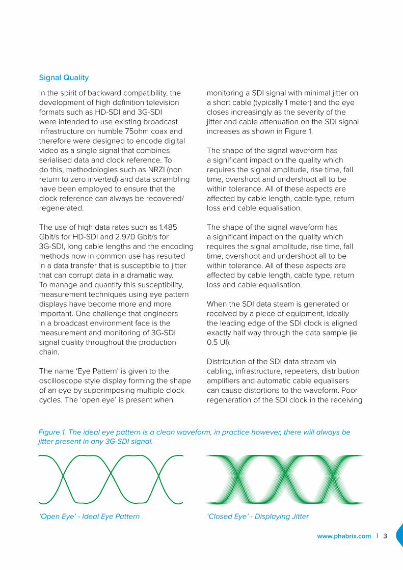
‘Open Eye’ - Ideal Eye Pattern
Signal Quality
In the spirit of backward compatibility, the development of high definition television formats such as HD-SDI and 3G-SDI were intended to use existing broadcast infrastructure on humble 75ohm coax and therefore were designed to encode digital video as a single signal that combines serialised data and clock reference. To do this, methodologies such as NRZI (non return to zero inverted) and data scrambling have been employed to ensure that the clock reference can always be recovered/ regenerated.
The use of high data rates such as 1.485 Gbit/s for HD-SDI and 2.970 Gbit/s for 3G-SDI, long cable lengths and the encoding methods now in common use has resulted in a data transfer that is susceptible to jitter that can corrupt data in a dramatic way. To manage and quantify this susceptibility, measurement techniques using eye pattern displays have become more and more important. One challenge that engineers in a broadcast environment face is the measurement and monitoring of 3G-SDI signal quality throughout the production chain.
The name ‘Eye Pattern’ is given to the oscilloscope style display forming the shape of an eye by superimposing multiple clock cycles. The ‘open eye’ is present when
monitoring a SDI signal with minimal jitter on a short cable (typically 1 meter) and the eye closes increasingly as the severity of the jitter and cable attenuation on the SDI signal increases as shown in Figure 1.
The shape of the signal waveform has a significant impact on the quality which requires the signal amplitude, rise time, fall time, overshoot and undershoot all to be within tolerance. All of these aspects are affected by cable length, cable type, return loss and cable equalisation.
The shape of the signal waveform has a significant impact on the quality which requires the signal amplitude, rise time, fall time, overshoot and undershoot all to be within tolerance. All of these aspects are affected by cable length, cable type, return loss and cable equalisation.
When the SDI data steam is generated or received by a piece of equipment, ideally the leading edge of the SDI clock is aligned exactly half way through the data sample (ie 0.5 UI).
Distribution of the SDI data stream via cabling, infrastructure, repeaters, distribution amplifiers and automatic cable equalisers can cause distortions to the waveform. Poor regeneration of the SDI clock in the receiving
‘Closed Eye’ - Displaying Jitter
Figure 1. The ideal eye pattern is a clean waveform, in practice however, there will always be jitter present in any 3G-SDI signal.

4 3G-SDI Signal Quality & Compliance Testing
equipment may cause the data stream to be sampled earlier or later in the Unit Interval (UI) which in turn will cause the wrong data samples to be taken.
See Figure 3
Testing of signal quality should focus on the tolerances defined in the SMPTE 424M specification which states that when measured at signal source with 1 meter cable:
• The signal amplitude should be 800mv +/- 10% (ie 880mV to 720mV)
• The rise/fall time of the 3Gb/s signal should be no greater than 135ps
• The difference between then rise time and fall time must not be more than 50ps
• The overshoot and overshoot must be less than 10%
The effect of jitter is displayed as feint lines before and after the ideal waveform on the eye waveform as shown in Figure 5. The greater the amount of jitter, the higher the risk of incorrect data samples being made. The result of incorrect data samples on the program’s video and audio content may be dramatic because individual incorrect bit samples could corrupt whole data words or even worse the serial-parallel frame words that define each video line.
The loss of individual video or audio samples may be acceptable, but the corruption of metadata may not be because it could affect everything downstream.
See Figure 4
Figure 2. Shows the Eye Pattern displayed on the PHABRIX SxE handheld instrument.
Figure 3. The shape of the 3G-SDI signal is critical to the correct decoding of the data stream and to ensure this the critical parameters are defined within SMPTE specifications
5www.phabrix.com
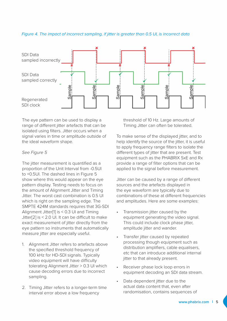
Figure 4. The impact of incorrect sampling, if jitter is greater than 0.5 UI, is incorrect data
SDI Data sampled incorrectly
SDI Data sampled correctly
Regenerated SDI clock
The eye pattern can be used to display a range of different jitter artefacts that can be isolated using filters. Jitter occurs when a signal varies in time or amplitude outside of the ideal waveform shape.
See Figure 5
The jitter measurement is quantified as a proportion of the Unit Interval from -0.5UI to +0.5UI. The dashed lines in Figure 5 show where this would appear on the eye pattern display. Testing needs to focus on the amount of Alignment Jitter and Timing Jitter. The worst cast combination is 0.5 UI which is right on the sampling edge. The SMPTE 424M standards requires that 3G-SDI Alignment Jitter[1] is < 0.3 UI and Timing Jitter[2] is < 2.0 UI. It can be difficult to make exact measurement of jitter directly from the eye pattern so instruments that automatically measure jitter are especially useful.
1. Alignment Jitter refers to artefacts above the specified threshold frequency of 100 kHz for HD-SDI signals. Typically video equipment will have difficulty tolerating Alignment Jitter > 0.3 UI which cause decoding errors due to incorrect sampling.
2. Timing Jitter refers to a longer-term time interval error above a low frequency
threshold of 10 Hz. Large amounts of Timing Jitter can often be tolerated.
To make sense of the displayed jitter, and to help identify the source of the jitter, it is useful to apply frequency range filters to isolate the different types of jitter that are present. Test equipment such as the PHABRIX SxE and Rx provide a range of filter options that can be applied to the signal before measurement.
Jitter can be caused by a range of different sources and the artefacts displayed in the eye waveform are typically due to combinations of these at different frequencies and amplitudes. Here are some examples:
• Transmission jitter caused by the equipment generating the video signal. This could include clock phase jitter, amplitude jitter and wander.
• Transfer jitter caused by repeated processing though equipment such as distribution amplifiers, cable equalisers, etc that can introduce additional internal jitter to that already present.
• Receiver phase lock loop errors in equipment decoding an SDI data stream.
• Data dependent jitter due to the actual data content that, even after randomisation, contains sequences of

6 3G-SDI Signal Quality & Compliance Testing
zeros or ones long enough for the clock recovery/regeneration to drift or loose phase lock with respect to the data.
• Thermal and Shot Noise caused by the integrated circuits used within equipment that can cause random errors.
• Electromagnetic interference in long cable runs that may be susceptible to the power grid and power switching.
• Waveform distortion due to equipment within the broadcast chain, long cable runs, poorly terminated or un-equalised cables, poor frequency response of cables or poor equipment return-loss.
Figure 5. The allowable jitter is defined as a proportion of the Unit Interval.
Signal Quality
Engineers and Manufactures alike face the challenge of dealing with the myriad of video formats that are now possible with 3G-SDI. Testing needs to ensure that equipment is correctly designed and that all formats are correctly supported.
The products designed and manufactured by PHABRIX now support more than 400 different format combinations. These have to be tested both in development and in production to ensure that they are compliant with SMPTE specifications. To do this the tools available within the PHABRIX Sx, Rx and Qx instruments themselves are used. Automated scripts and remote control are used to make systematic selection of generator test patterns, video formats, line rates, frame rates, colour spaces, bit depths, etc while these are monitored and errors reported using the inbuilt logging system.
This approach to large scale testing for compliance has also been adopted by manufacturers including AJA, Grass Valley and Evertz.
Compatibility with future advances
Emerging 2K digital cinema and 3D format production is becoming more widespread and existing infrastructure may not fully or transparently handle these advances in technology. The ability to inject a specific video format into the production chain and monitor it at each stage can ease the introduction of these new formats as well as fault find when things are not working correctly.
3G-SDI T&M equipment has to provide tools for these emerging formats to allow the engineers and equipment manufacturers to quickly check that they are supported. The use of ‘analogue type’ displays (such as

7www.phabrix.com
ConclusionThe testing of 3G-SDI, like all new innovations, takes time for the industry to gets to grips with and will be well established standard practice just in time for the next round of innovation. The knowledge, skills and experience gained by the industry during the implementation of HD-SDI are directly applicable to 3G-SDI.
The parameters and tolerances defined in SMPTE 424M specification for 3G-SDI are even more critical than those defined in SMPTE 292M for HD-SDI therefore testing of signal quality and compliance is paramount to ensuring correct and reliable functionality.
picture monitor, vectorscope and waveform monitor) give the engineer an instant view of the decoded data within the 3G-SDI feed to provide a level of confidence that the image data is correct.
Decoding and displaying the Ancillary data within the 3G-SDI feed allows the engineer to check its integrity and compatibility with other equipment.
For example SMPTE 428-9 “D-Cinema Distribution Master - Image Pixel Structure Level 3 - Serial Digital Interface Signal Formatting” employs CIE XYZ space instead of the more traditional YCrCb or RGB colour spaces, 2048 x 1080 pixels and 24 frames/s or 48 frames/s. The audio for digital cinema is up to 16 channels of broadcast WAV or uncompressed 24-bit samples at 48kHz or 96 kHz.
Stereoscopic Television can also employs CIE XYZ colour space, 2048 x 1080 pixels, however is has frame rate of 48 frames/s (24 frames/s per eye).
Developments in the PHABRIX Sx, Rx and Qx analysers now support 2K XYZ colour space formats and sample rates, as well as 2K digital cinema as defined in the SMPTE ST 2048-2:2011 standard (“2048 x 1080 Digital Cinematography Production Image FS/709 Formatting for Serial Digital Interface”). Here 2K material is displayed in ‘analogue form’ as picture, waveform and vectorscope to allow users to check for possible errors
that may have been introduced by format conversions or equipment that does not accurately transform between YCrCB, RGB and XYZ colour spaces. The 2K test patterns also available on these instruments allow ‘before and after’ comparisons to be made as 2K material is processed and distributed. The standard test patterns used in HD-SDI test and measurements are now available in the 2K world to allow broadcast engineers to comfortably use their skills in the digital cinema world.
As with HD-SDI the metadata is a vitally important part of the content of the 3G-SDI data stream and now contains even more complex information that defines the content, mapping and colour space information for the material being distributed. An understanding of this metadata is critical to transparent processing (routing, switching, editing, insertion, etc) as well as a method of checking the actual metadata present in the data stream.
CRC based content checking, measured over long periods of time, ensures that no data errors are present in the transmission.
T&M equipment such as the PHABRIX Sx, Rx and Qx allow the detailed analysis and logging of the metadata used, including the SMPTE RP 215 and SMPTE 352 payloads (which define the video format, frame rate, line rate, colour space and data mapping) and CRC errors in the video data and metadata.

www.phabrix.com
For more information about our 3G-SDI test
and measurement solutions, contact:
Related Documents