Version 1.0(A-E) 3e Technologies International, Inc. FIPS 140-2 Non-Proprietary Security Policy Level 2 Validation 3e-525A-3 AirGuard TM Wireless Access Point & 3e-525V-3 AirGuard TM Wireless Access Point HW Versions 1.0(A-E) FW Version 4.0.9.11 February 2, 2007 Copyright 2007 by 3e Technologies International. This document may freely be reproduced and distributed in its entirety.

Welcome message from author
This document is posted to help you gain knowledge. Please leave a comment to let me know what you think about it! Share it to your friends and learn new things together.
Transcript
Version 1.0(A-E)
3e Technologies International, Inc. FIPS 140-2
Non-Proprietary Security Policy Level 2 Validation
3e-525A-3 AirGuardTM Wireless Access Point &
3e-525V-3 AirGuardTM Wireless Access Point
HW Versions 1.0(A-E) FW Version 4.0.9.11
February 2, 2007
Copyright 2007 by 3e Technologies International. This document may freely be reproduced and distributed in its entirety.
FIPS 140-2 Non-Proprietary Security Policy
Version 1.0(A-E) 2
GLOSSARY OF TERMS................................................................................................. 3
1. INTRODUCTION .................................................................................................... 4
1.1. PURPOSE.............................................................................................................. 4 1.2. DEFINITION .......................................................................................................... 5 1.3. SCOPE.................................................................................................................. 6 1.4. HARDWARE CHANGES BETWEEN HW V1.0 V(A-D) AND HW V1.0(E):............. 7
2. ROLES, SERVICES, AND AUTHENTICATION................................................ 8
2.1.1. Roles and Services ...................................................................................... 8 2.1.2. Authentication Mechanisms and Strength ................................................ 13
3. SECURE OPERATION AND SECURITY RULES ........................................... 14
3.1. SECURITY RULES............................................................................................... 14 3.2. PHYSICAL SECURITY RULES .............................................................................. 14 3.3. SECURE OPERATION INITIALIZATION ................................................................. 17
4. SECURITY RELEVANT DATA ITEMS ............................................................ 18
4.1. CRYPTOGRAPHIC ALGORITHMS ......................................................................... 18 4.2 SELF-TESTS........................................................................................................ 18 4.3 CRYPTOGRAPHIC KEYS AND SRDIS .................................................................. 19 4.4 ACCESS CONTROL POLICY ................................................................................. 21

FIPS 140-2 Non-Proprietary Security Policy
Version 1.0(A-E) 3
Glossary of terms AP Access Point CO Cryptographic Officer DH Diffie Hellman DHCP Dynamic Host Configuration Protocol DMZ De-Militarized Zone IP Internet Protocol EAP Extensible Authentication Protocol FIPS Federal Information Processing Standard HTTPS Secure Hyper Text Transport Protocol LAN Local Area Network MAC Medium Access Control NAT Network Address Translation PRNG Pseudo Random Number Generator RSA Rivest, Shamir, Adleman SHA Secure Hash Algorithm SRDI Security Relevant Data Item SSID Service Set Identifier TLS Transport Layer Security WAN Wide Area Network WLAN Wireless Local Area Network
FIPS 140-2 Non-Proprietary Security Policy
Version 1.0(A-E) 4
1. Introduction
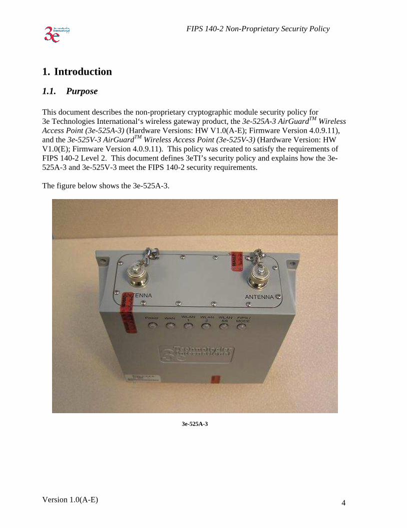
1.1. Purpose This document describes the non-proprietary cryptographic module security policy for 3e Technologies International‘s wireless gateway product, the 3e-525A-3 AirGuardTM Wireless Access Point (3e-525A-3) (Hardware Versions: HW V1.0(A-E); Firmware Version 4.0.9.11), and the 3e-525V-3 AirGuardTM Wireless Access Point (3e-525V-3) (Hardware Version: HW V1.0(E); Firmware Version 4.0.9.11). This policy was created to satisfy the requirements of FIPS 140-2 Level 2. This document defines 3eTI’s security policy and explains how the 3e-525A-3 and 3e-525V-3 meet the FIPS 140-2 security requirements. The figure below shows the 3e-525A-3.
3e-525A-3
FIPS 140-2 Non-Proprietary Security Policy
Version 1.0(A-E) 5
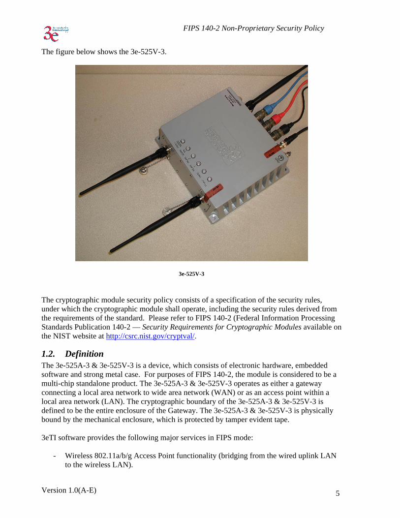
The figure below shows the 3e-525V-3.
3e-525V-3
The cryptographic module security policy consists of a specification of the security rules, under which the cryptographic module shall operate, including the security rules derived from the requirements of the standard. Please refer to FIPS 140-2 (Federal Information Processing Standards Publication 140-2 — Security Requirements for Cryptographic Modules available on the NIST website at http://csrc.nist.gov/cryptval/.
1.2. Definition The 3e-525A-3 & 3e-525V-3 is a device, which consists of electronic hardware, embedded software and strong metal case. For purposes of FIPS 140-2, the module is considered to be a multi-chip standalone product. The 3e-525A-3 & 3e-525V-3 operates as either a gateway connecting a local area network to wide area network (WAN) or as an access point within a local area network (LAN). The cryptographic boundary of the 3e-525A-3 & 3e-525V-3 is defined to be the entire enclosure of the Gateway. The 3e-525A-3 & 3e-525V-3 is physically bound by the mechanical enclosure, which is protected by tamper evident tape. 3eTI software provides the following major services in FIPS mode:
- Wireless 802.11a/b/g Access Point functionality (bridging from the wired uplink LAN to the wireless LAN).
FIPS 140-2 Non-Proprietary Security Policy
Version 1.0(A-E) 6
- Wireless 802.11a/b/g bridge functionality - DHCP service to the local LAN (allows a wired local LAN to exist over the local LAN
interface). - SNMP∗ - Subnet Roaming - Virtual LAN - 802.11i - 64MB Xscale Card Revision D and Revision E.
1.3. Scope This document will cover the secure operation of the 3e-525A-3 & 3e-525V-3 including the initialization, roles and responsibilities of operating the product in a secure, FIPS-compliant manner, and describe the Security Relevant Data Items (SRDIs). The Gateway has four modes of operations, which are listed in the table below:
Mode FIPS Mode Gateway Mode (Mode 1) No Gateway Mode (Mode 2) Yes
AP / Bridging Mode (Mode 1) No AP /Bridging Mode (Mode 2) Yes
The Gateway - FIPS mode (Mode 2) and AP/Bridging - FIPS mode (Mode 2) are explained in this document. The other modes cannot be validated by FIPS because they employ protocols that use non-FIPS cryptographic algorithms. In order to enter FIPS mode, select the FIPS 140-2 Mode box on the Operation Mode page of the management GUI (refer to 3e-525A-3 & 3e-525V-3 User Manual). This will force the 3e-525A-3 & 3e-525V-3 to return to factory defaults and then the unit will reboot into FIPS mode. To leave FIPS mode, un-select the FIPS 140-2 Mode box and apply the changes. Once again, the 3e-525A-3 & 3e-525V-3 will restore factory defaults and then reboot into non-FIPS mode. On transition between modes, the system is returned to factory defaults.
∗ Although SNMP traffic is transmitted encrypted (using DES or AES), for FIPS purposes, it is considered to be plaintext. The reason being, encryption keys are derived from a pass-phrase, which is not allowed in FIPS mode.
FIPS 140-2 Non-Proprietary Security Policy
Version 1.0(A-E) 7
1.4. Hardware Changes between HW V1.0 V(A-D) and HW V1.0(E): Hardware Version E contains: - New POE board with 35W DC-DC converter (replacing original DC-DC converter). - New thermal pad between POE board & enclosure wall - All USB circuitry removed from XScale mainboard The 3e-525V-3:
The new 3e-525V-3 hardware version including the additional physical interfaces (video BNC in), the changed physical interfaces (serial Camera control out), as well as the other differences between the existing validated gateway (3e-525V-3) and the Product (these changes would include removed serial access to the Product’s mainboard), modified power daughter board (POE) to meet the 802.3AF POE requirements, increased size of the thermal pads to allow the module to pass shock & vibrations testing, "minor" mechanical changes, e.g., changes to the part vendor supplying a connector, and the new part now includes an o-ring—thus they removed the separate O-ring part.
There is a difference between the ports of the 3e-525A-3 and the 3e-525V-3. The 3e-525V-3 includes the Video BNC out and the use of the Data I/O port for serial camera control out on the 3e-525V-3 (no use on the 3e-525A-3 for the Data I/O port).
Version 1.0(A-E)
2. Roles, Services, and Authentication The 3e-525A-3 & 3e-525V-3 supports four separate roles. The set of services available to each role is defined in this section. The 3e-525A-3 & 3e-525V-3 authenticates an operator’s role by verifying his PIN or access to a shared secret.
2.1.1. Roles and Services The 3e-525A-3 & 3e-525V-3 supports the following authorized roles for operators: Crypto Officer Role: The Crypto officer role performs all security functions provided by the 3e-525A-3 & 3e-525V-3. This role performs cryptographic initialization and management functions (e.g., module initialization, input/output of cryptographic keys and SRDIs, audit functions and user management). The Crypto officer is also responsible for managing the Administrator users. The Crypto officer must operate within the Security Rules and Physical Security Rules specified in Sections 3.1 and 3.2. The Crypto officer uses a secure web-based HTTPS connection to configure the 3e-525A-3 & 3e-525V-3. Up to ten Crypto Officers may be defined in the 3e-525A-3 & 3e-525V-3. The Crypto Officer authenticates to the 3e-525A-3 & 3e-525V-3 using a username and password. Administrator Role: This role performs general 3e-525A-3 & 3e-525V-3 configuration such as defining the WLAN, LAN and DHCP settings, performing self-tests and viewing system log messages for auditing purposes. No CO security functions are available to the Administrator. The Administrator can also reboot the 3e-525A-3 & 3e-525V-3, if deemed necessary. The Administrator must operate within the Security Rules a specified in Section 3.1 and always uses a secure web-based HTTPS connection to configure the 3e-525A-3 & 3e-525V-3. The Administrator authenticates to the 3e-525A-3 & 3e-525V-3 using a username and password. Up to 5 operators who can assume the Administrator role can be defined. All Administrators are identical; i.e., they have the same set of services available. The Crypto Officer is responsible for managing (creating, deleting) Administrator users.

FIPS 140-2 Non-Proprietary Security Policy
Version 1.0(A-E) 9
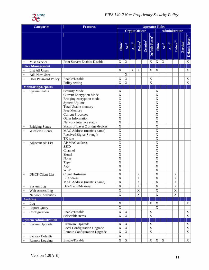
The follow table outlines the functionalities that are provided by each role:
Operator Roles Categories Features CryptoOfficer Administrator
Sho
w1
Set
2
Add
3
Del
ete4
Zer
oize
5
Def
ault
Res
et6
Sho
w7
Set
8
Add
9
Del
ete10
Zer
oize
11
Def
ault
Res
et12
System Configuration • General Hostname
Domain name Date/Time
X X X
X X X
X X X
X X X
X X X
X X X
• WAN DHCP client Static IP address 10/100 MBps half/full duplex/auto
X X X
X X X
X XX
X X X
X X X
X X X
• LAN IP address Subnet mask
X X
X X
X X
X X
X X
X X
• Operating Mode Gateway – FIPS Gateway – Non-FIPS AP / Bridging Mode – FIPS AP / Bridging Mode – Non-FIPS AP / Bridging Mode – FIPS / IPv6 AP / Bridging Mode – Non-FIPS / IPv6
X X X X X X
X XX X X X
XXX X X X
XXX X X X
XXX X X X
XXX X X X
Wireless Access Point • General SSID
Wireless Mode Channel Number • Enable / Disable Auto Selection • Auto selection button Transmit Power Mode Fixed Power Level Beacon Interval RTS Threshold DTIM Basic Rates
X X XXXXXXXXX
X X XXXXXXXXX
X X XXXXXXXXX
X X XXXXXXXXX
X X XXXXXXXXX
X X XXXXXXXXX
1 The operator can view this setting 2 The operator can change this setting 3 The operator can add a required input. For example: Adding an entry to the MAC address filtering table 4 The operator can delete a particular entry. For example: Deleting an entry from the MAC address filtering table 5 The operator can zeroize these keys. 6 The operator can reset this setting to its factory default value. This is done by performing a zeroize 7 The operator can view this setting 8 The operator can change this setting 9 The operator can add a required input. For example: Adding an entry to the MAC address filtering table 10 The operator can delete a particular entry. For example: Deleting an entry from the MAC address filtering table 11 The operator can zeroize these keys. 12 The operator can reset this setting to its factory default value. This is done by performing a zeroize

FIPS 140-2 Non-Proprietary Security Policy
Version 1.0(A-E) 10
Operator Roles Categories Features CryptoOfficer Administrator
Sho
w1
Set
2
Add
3
Del
ete4
Zer
oize
5
Def
ault
Res
et6
Sho
w7
Set
8
Add
9
Del
ete10
Zer
oize
11
Def
ault
Res
et12
Preamble Enable / Disable Broadcast SSID
XX
XX
XX
XX
XX
XX
• Security No Encryption Dynamic Key Management 3DES AES (128-/192-256-bit) FIPS 802.11i
X X XX X
X X XX X
X X
X X XX X
X X XX X
• Wireless VLAN Enable/Disable VLAN
X X
X X
X
X
X
X X
X X
• MAC Address Filtering
Enable/Disable Add/Delete entry Allow/Disallow Filter
X
X
X
X
X
X
X
X
X
X
X
X • Rogue AP Detection Enable/Disable
Known AP MAC address Email / Display rogue AP
X
X
X
X
X
X
X
X
X
X
X
X
X
X • Advanced Load Balancing
Layer 2 Isolation X X
X X
X X
X X
X X
X X
Wireless Bridge • General Manual/Auto Bridge
SSID Max Auto Bridge Bridge Priority Signal Strength Threshold Broadcast SSID enable/disable Signal Strength LED MAC STP enable/disable Remote BSSID
XXXXXX X X X
X XXXXX X X X
X
X X X X X X X X X
X X X X X X X X X
X X X X X X X X X
X
X X X X X X X X X
• Radio Wireless Mode Tx Rate Channel No Tx Pwr Mode Propagation Distance RTS Threshold Remote BSSID
X X X X X X
XX X X X X
X
X X X X X X
X X X X X X
X X X X X X
X
X X X X X X
• Encryption No Encryption 3DES AES (128-/192-256-bit)
X XX
XXX
XX
XX
XXX
XXX
Service Settings • DHCP Server Enable / Disable
Starting / Ending IP address XX
XX
XX
XX
XX
X X
• Subnet Roaming Enable / Disable Coordinator Address
X X
X X
X
X X
X X
X X
X
X X
• SNMP agent Enable/ Disable Community settings Secure User Configuration System Information
X X X X
X X X X
X X X X
X X X X
X X X X
X X X X
FIPS 140-2 Non-Proprietary Security Policy
Version 1.0(A-E) 11
Operator Roles Categories Features CryptoOfficer Administrator
Sho
w1
Set
2
Add
3
Del
ete4
Zer
oize
5
Def
ault
Res
et6
Sho
w7
Set
8
Add
9
Del
ete10
Zer
oize
11
Def
ault
Res
et12
• Misc Service Print Server: Enable/ Disable X X X X X X User Management • List All Users X X X X X X • Add New User X • User Password Policy Enable/Disable
Policy setting X X
X X
X X
X X
Monitoring/Reports • System Status Security Mode
Current Encryption Mode Bridging encryption mode System Uptime Total Usable memory Free Memory Current Processes Other Information Network interface status
X XXXXXXXX
X X X X X X X XX
• Bridging Status Status of Layer 2 bridge devices X X • Wireless Clients MAC Address (manfr’s name)
Received Signal Strength TX rate
X X X
X X X
• Adjacent AP List AP MAC address SSID Channel Signal Noise Type Age WEP
X X X XXXXX
XXXXXXXX
• DHCP Client List Client Hostname IP Address MAC Address (manfr’s name)
X X X
X X X
XXX
XXX
• System Log Date/Time/Message X X X X • Web Access Log X X X X • Network Activities X X X X Auditing • Log X X X X • Report Query X X • Configuration Enable/Disable
Selectable items X X
X X
X X
X X
System Administration • System Upgrade Firmware Upgrade
Local Configuration Upgrade Remote Configuration Upgrade
X X X
X X X
X X X
X X X
• Factory Defaults X • Remote Logging Enable/Disable X X X X X X
FIPS 140-2 Non-Proprietary Security Policy
Version 1.0(A-E) 12
Operator Roles Categories Features CryptoOfficer Administrator
Sho
w1
Set
2
Add
3
Del
ete4
Zer
oize
5
Def
ault
Res
et6
Sho
w7
Set
8
Add
9
Del
ete10
Zer
oize
11
Def
ault
Res
et12
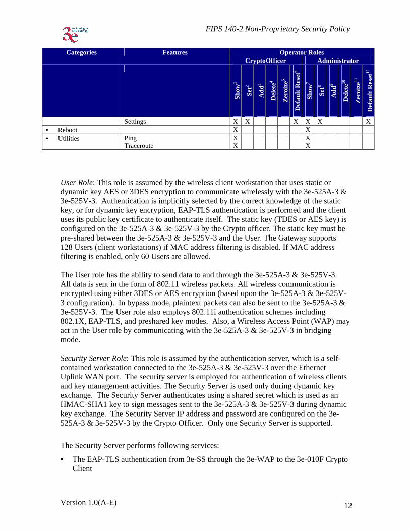
Settings X X X X X X • Reboot X X • Utilities Ping
Traceroute X X
X X
User Role: This role is assumed by the wireless client workstation that uses static or dynamic key AES or 3DES encryption to communicate wirelessly with the 3e-525A-3 & 3e-525V-3. Authentication is implicitly selected by the correct knowledge of the static key, or for dynamic key encryption, EAP-TLS authentication is performed and the client uses its public key certificate to authenticate itself. The static key (TDES or AES key) is configured on the 3e-525A-3 & 3e-525V-3 by the Crypto officer. The static key must be pre-shared between the 3e-525A-3 & 3e-525V-3 and the User. The Gateway supports 128 Users (client workstations) if MAC address filtering is disabled. If MAC address filtering is enabled, only 60 Users are allowed. The User role has the ability to send data to and through the 3e-525A-3 & 3e-525V-3. All data is sent in the form of 802.11 wireless packets. All wireless communication is encrypted using either 3DES or AES encryption (based upon the 3e-525A-3 & 3e-525V-3 configuration). In bypass mode, plaintext packets can also be sent to the 3e-525A-3 & 3e-525V-3. The User role also employs 802.11i authentication schemes including 802.1X, EAP-TLS, and preshared key modes. Also, a Wireless Access Point (WAP) may act in the User role by communicating with the 3e-525A-3 & 3e-525V-3 in bridging mode. Security Server Role: This role is assumed by the authentication server, which is a self-contained workstation connected to the 3e-525A-3 & 3e-525V-3 over the Ethernet Uplink WAN port. The security server is employed for authentication of wireless clients and key management activities. The Security Server is used only during dynamic key exchange. The Security Server authenticates using a shared secret which is used as an HMAC-SHA1 key to sign messages sent to the 3e-525A-3 & 3e-525V-3 during dynamic key exchange. The Security Server IP address and password are configured on the 3e-525A-3 & 3e-525V-3 by the Crypto Officer. Only one Security Server is supported.
The Security Server performs following services:
• The EAP-TLS authentication from 3e-SS through the 3e-WAP to the 3e-010F Crypto Client
FIPS 140-2 Non-Proprietary Security Policy
Version 1.0(A-E) 13
• Process dynamic key exchange after a successful authentication • Perform a DH key exchange with the 3e-525A-3 & 3e-525V-3 to negotiate an AES
key • Send Unicast key to the Gateway encrypted with the AES key negotiated using a DH
key exchange
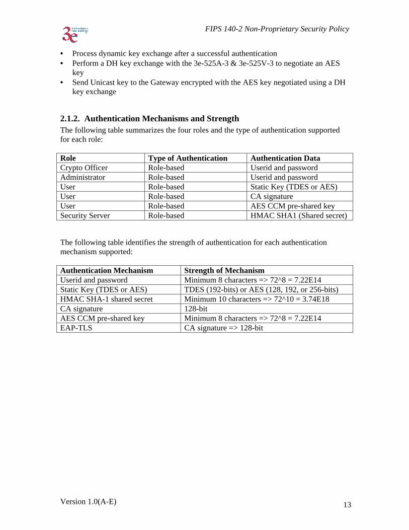
2.1.2. Authentication Mechanisms and Strength The following table summarizes the four roles and the type of authentication supported for each role: Role Type of Authentication Authentication Data Crypto Officer Role-based Userid and password Administrator Role-based Userid and password User Role-based Static Key (TDES or AES) User Role-based CA signature User Role-based AES CCM pre-shared key Security Server Role-based HMAC SHA1 (Shared secret)
The following table identifies the strength of authentication for each authentication mechanism supported: Authentication Mechanism Strength of Mechanism Userid and password Minimum 8 characters => 72^8 = 7.22E14 Static Key (TDES or AES) TDES (192-bits) or AES (128, 192, or 256-bits) HMAC SHA-1 shared secret Minimum 10 characters => 72^10 = 3.74E18 CA signature 128-bit AES CCM pre-shared key Minimum 8 characters => 72^8 = 7.22E14 EAP-TLS CA signature => 128-bit
FIPS 140-2 Non-Proprietary Security Policy
Version 1.0(A-E) 14
3. Secure Operation and Security Rules In order to operate the 3e-525A-3 & 3e-525V-3 securely, each operator should be aware of the security rules enforced by the module and should adhere to the physical security rules and secure operation rules detailed in this section.
3.1. Security Rules The following 3e-525A-3 & 3e-525V-3 security rules must be followed by the operator in order to ensure secure operation:
1. Every operator (Crypto Officer or Administrator) has a user-id on the 3e-525A-3 & 3e-525V-3. No operator will violate trust by sharing his/her password associated with the user-id with any other operator or entity.
2. The Crypto Officer will not share any key, or SRDI used by the 3e-525A-3 & 3e-525V-3 with any other operator or entity.
3. The Crypto Officer will not share any MAC address filtering information used by the 3e-525A-3 & 3e-525V-3 with any other operator or entity.
4. The operators will explicitly logoff by closing all secure browser sessions established with the 3e-525A-3 & 3e-525V-3.
5. The operator will disable browser cookies and password storing mechanisms on the browser used for web configuration of the 3e-525A-3 & 3e-525V-3.
6. The Crypto officer is responsible for inspecting the tamper evident seals on a daily basis. A compromised tape reveals message “OPENED” with visible red dots. Other signs of tamper include wrinkles, tears and marks on or around the label.
7. The Crypto Officer should change the default password when configuring the 3e-525A-3 & 3e-525V-3 for the first time. The default password should not be used.
3.2. Physical Security Rules The following section contains detailed instructions to the Crypto Officer concerning where and how to apply the tamper evident seals to the 3e-525A-3 & 3e-525V-3 enclosure, in order to provide physical security for FIPS 140-2 level 2 requirements. A security seal is added from the back plate to the antenna plate. A second security seal is added from the front of the unit to the antenna plate, taking care not to cover the L.E.D. labeling. A ½” 440 Pan Head screw replaces one of the 5/8” 440 Pan Head screws on each circular connector. Then two 440 kepts nuts are added and tightened together with washers facing each other approximately 1/32” from the connector panel. This prevents the screws from being removed and thus entry cannot be accomplished without removing the security labels. Materials:
3e-525A-3 & 3e-525V-3 – Quantity: 1 Seal, Tape, Tamper-evident – Quantity: 4

FIPS 140-2 Non-Proprietary Security Policy
Version 1.0(A-E) 15
Isopropyl Alcohol Swab 3M Adhesive Remover (citrus or petroleum based solvent)
Installation – Tamper-evident tape
1. Locate on 3e-525A-3 & 3e-525V-3 the placement locations of tamper-evident
tape seals. (4 locations as shown in the figures below for the 3e-525A-3 & 3e-525V-3).
2. Thoroughly clean area where tamper-evident tape seal is to be applied with isopropyl alcohol swab. Area must be clean of all oils and foreign matter (dirt, grime, etc.)
3. Record tracking number from tamper-evident tape seal. 4. Apply seal to locations on the 3e-525A-3 & 3e-525V-3 as shown in the figure
below. It is important to ensure that the seal has equal contact area with both top and bottom housings.
5. After application of seals to the 3e-525A-3 & 3e-525V-3, apply pressure to verify that adequate adhesion has taken place.
Removal – Tamper-evident tape
1. Locate on 3e-525A-3 & 3e-525V-3 locations of tamper-evident tape seals. (4 locations (two on each panel) as shown in the figure below for the 3e-525A-3 & 3e-525V-3)
2. Record tracking numbers from existing tamper-evident tape seal and verify physical condition as not tampered or destroyed after installation.
3. Cut tape along seam of 3e-525A-3 & 3e-525V-3 to allow opening of enclosure. 4. Using 3M adhesive remover or equivalent, remove residual tamper-evident seal
tape. (two locations as shown in the figure below for the 3e-525A-3 & 3e-525V-3)
FIPS 140-2 Non-Proprietary Security Policy
Version 1.0(A-E) 16
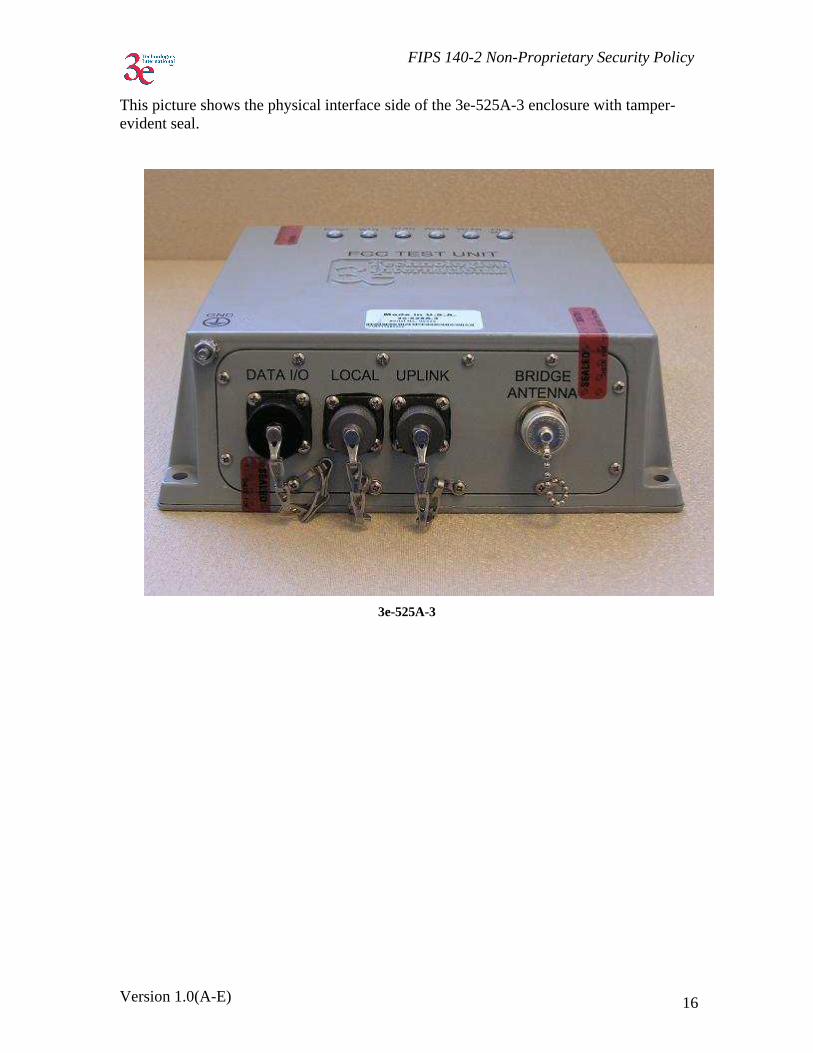
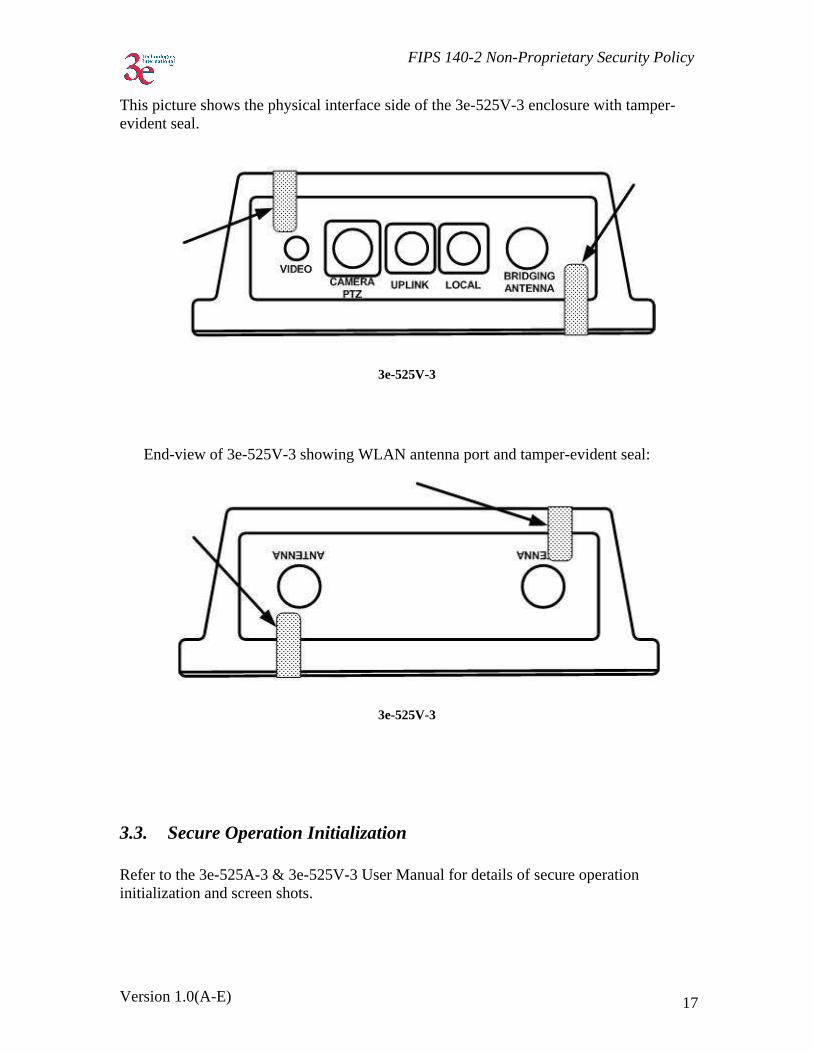
This picture shows the physical interface side of the 3e-525A-3 enclosure with tamper-evident seal.
3e-525A-3
FIPS 140-2 Non-Proprietary Security Policy
Version 1.0(A-E) 17
This picture shows the physical interface side of the 3e-525V-3 enclosure with tamper-evident seal.
3e-525V-3
End-view of 3e-525V-3 showing WLAN antenna port and tamper-evident seal:
3e-525V-3
3.3. Secure Operation Initialization Refer to the 3e-525A-3 & 3e-525V-3 User Manual for details of secure operation initialization and screen shots.
FIPS 140-2 Non-Proprietary Security Policy
Version 1.0(A-E) 18
4. Security Relevant Data Items This section specifies the 3e-525A-3 & 3e-525V-3’s Security Relevant Data Items (SRDIs) as well as the access control policy enforced by the 3e-525A-3 & 3e-525V-3.
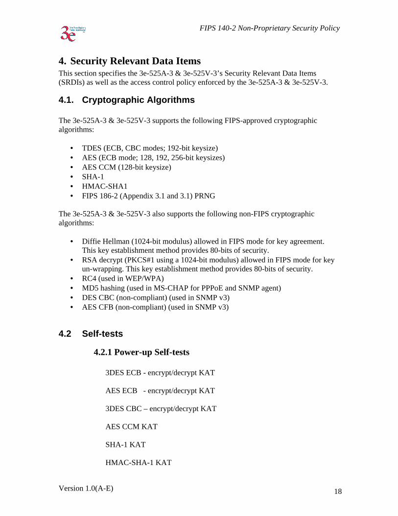
4.1. Cryptographic Algorithms The 3e-525A-3 & 3e-525V-3 supports the following FIPS-approved cryptographic algorithms:
• TDES (ECB, CBC modes; 192-bit keysize) • AES (ECB mode; 128, 192, 256-bit keysizes) • AES CCM (128-bit keysize) • SHA-1 • HMAC-SHA1 • FIPS 186-2 (Appendix 3.1 and 3.1) PRNG
The 3e-525A-3 & 3e-525V-3 also supports the following non-FIPS cryptographic algorithms:
• Diffie Hellman (1024-bit modulus) allowed in FIPS mode for key agreement. This key establishment method provides 80-bits of security.
• RSA decrypt (PKCS#1 using a 1024-bit modulus) allowed in FIPS mode for key un-wrapping. This key establishment method provides 80-bits of security.
• RC4 (used in WEP/WPA) • MD5 hashing (used in MS-CHAP for PPPoE and SNMP agent) • DES CBC (non-compliant) (used in SNMP v3) • AES CFB (non-compliant) (used in SNMP v3)
4.2 Self-tests
4.2.1 Power-up Self-tests 3DES ECB - encrypt/decrypt KAT
AES ECB - encrypt/decrypt KAT 3DES CBC – encrypt/decrypt KAT AES CCM KAT
SHA-1 KAT
HMAC-SHA-1 KAT

FIPS 140-2 Non-Proprietary Security Policy
Version 1.0(A-E) 19
FIPS 186-2 (Appendix 3.1, 3.3) RNG KAT
SHA-1 Integrity Test for firmware
4.2.2 Conditional Self-tests CRNGT for Approved PRNG
CRNGT for non-Approved PRNG (Open SSL based RNG)
Bypass Test
Firmware Load Test using HMAC-SHA-1
4.2.3 Critical Functions tests DH pairwise consistency test (power-up)
4.3 Cryptographic Keys and SRDIs The 3e-525A-3 & 3e-525V-3 contains the following security relevant data items:
Type ID Storage Location
Form Zeroizable Zeroization Mechanism
Function
Plaintext Keys AES ECB
256 bit “AES internal key to encrypt
config file”
FLASH Plaintext (inaccessible)
Y Zeroized by upgrading firmware
To protect the configuration
file PMK
256 bit “pairwise
master key” RAM Plaintext
(inaccessible) Y By changing the
mode to FIPS-11i or static key encryption
Master key used to derive
PTK
GMK 256 bit
“group master key”
RAM Plaintext (inaccessible)
Y By changing the mode to FIPS-11i
or static key encryption
Master key used to derive
GTK
AES Dynamic Broadcast
128,192, or 256 bit
“dynamic broadcast AES
key”
RAM Plaintext (inaccessible)
Y By changing the mode to FIPS-11i
or static key encryption
Client Access
3DES Dynamic Broadcast
192 bit
“dynamic broadcast 3DES
key”
RAM Plaintext (inaccessible)
Y By changing the mode to FIPS-11i
or static key encryption
Client Access
AES Dynamic Unicast
128,192, or 256 bit
“dynamic unicast AES
key”
RAM Plaintext (inaccessible)
Y By changing the mode to FIPS-11i
or static key encryption
Client Access
3DES Dynamic Unicast 192 bit
“dynamic unicast 3DES
key”
RAM Plaintext (inaccessible)
Y By changing the mode to FIPS-11i
or static key
Client Access

FIPS 140-2 Non-Proprietary Security Policy
Version 1.0(A-E) 20
encryption RNG Seed Key
160 bit “RNG seed
key” RAM Plaintext
(inaccessible) Y Zeroized
immediately following use
(after function is called & returned)
To generate the RNG
AES post-authentication
128 bit
“post - authentication
AES key”
RAM Plaintext (inaccessible)
Y Zeroized after the unicast key
(encrypted by this AES key) is decrypted by the
module
N/A
AES-CCM Dynamic
Broadcast 128 bit
(GTK)
“dynamic broadcast AES-CCM key use for FIPS-11i”
RAM Plaintext (inaccessible)
Y By changing encryption mode to DKE or static key encryption
Client Access
KCK 128 bit
“key MIC key” RAM Plaintext (inaccessible)
Y By changing encryption mode to DKE or static key encryption
To generate MIC in 802.11i key message
KEK 128 bit
“key encryption key”
RAM Plaintext (inaccessible)
Y By changing encryption mode to DKE or static key encryption
To encrypt GTK in
802.11i key message
AES-CCM Dynamic
Unicast 128 bit (TK)
“dynamic unicast AES-CCM key use for FIPS-11i”
RAM Plaintext (inaccessible)
Y By changing encryption mode to DKE or static key encryption
Client Access
802.11i pre-shared
passphrase 8 to 63 chars
“802.11i pre-shared
passphrase”
RAM Plaintext (inaccessible)
Y By changing the mode to FIPS-11i
or static key encryption
Used to generate PMK
Downloaded configuration file password
“downloaded config file pwd”
RAM Plaintext (inaccessible)
Y Zeroized immediately following use
(after function is called & returned)
To protect the configuration
file when downloaded
RSA Private Key
“HTTPS/TLS RSA private
key”
FLASH Plaintext (inaccessible)
Y Setting the module to factory
default
N/A
HMAC-SHA-1 key (1)
“firmware integrity check
key for firmware load
test”
FLASH Plaintext (inaccessible, hard-coded)
Y Zeroized by upgrading firmware
N/A
HMAC-SHA-1 key (3)
SNMP packet authentication
key
FLASH Plaintext Y Setting the module to factory
default
N/A
TLS Session Key
“HTTPS/TLS session key”
RAM Plaintext (inaccessible)
Y When the module is powered down.
N/A
Diffie-Hellman Private
“diffie-hellman prime”
RAM Plaintext Y Zeroized after the unicast key
N/A
FIPS 140-2 Non-Proprietary Security Policy
Version 1.0(A-E) 21
Exponent, 1024-bit
(encrypted by the established AES key) is decrypted
by the module Web-GUI logon
password for the Crypto
Officer
“CO web-GUI logon
password”
FLASH Hashed using SHA-1
Y Setting the module to factory
default
CO logon credential.
Web-GUI logon password for
the Administrator
“Admin web-GUI logon password”
FLASH Hashed using SHA-1
Y Setting the module to factory
default
Admin logon credential.
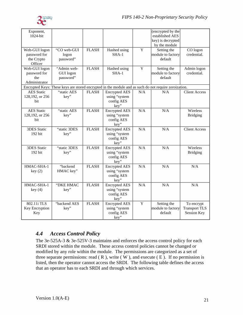
Encrypted Keys: These keys are stored encrypted in the module and as such do not require zeroization. AES Static
128,192, or 256 bit
“static AES key”
FLASH Encrypted AES using “system config AES
key”
N/A N/A Client Access
AES Static 128,192, or 256
bit
“static AES key”
FLASH Encrypted AES using “system config AES
key”
N/A N/A Wireless Bridging
3DES Static 192 bit
“static 3DES key”
FLASH Encrypted AES using “system config AES
key”
N/A N/A Client Access
3DES Static 192 bit
“static 3DES key”
FLASH Encrypted AES using “system config AES
key”
N/A N/A Wireless Bridging
HMAC-SHA-1 key (2)
“backend HMAC key”
FLASH Encrypted AES using “system config AES
key”
N/A N/A N/A
HMAC-SHA-1 key (4)
“DKE HMAC key”
FLASH Encrypted AES using “system config AES
key”
N/A N/A N/A
802.11i TLS Key Encryption
Key
“backend AES key”
FLASH Encrypted AES using “system config AES
key”
Y Setting the module to factory
default
To encrypt Transport TLS Session Key
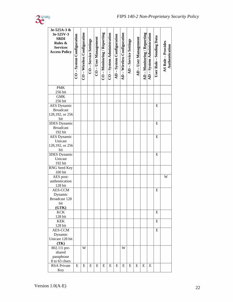
4.4 Access Control Policy The 3e-525A-3 & 3e-525V-3 maintains and enforces the access control policy for each SRDI stored within the module. These access control policies cannot be changed or modified by any role within the module. The permissions are categorized as a set of three separate permissions: read ( R ), write ( W ), and execute ( E ). If no permission is listed, then the operator cannot access the SRDI. The following table defines the access that an operator has to each SRDI and through which services.
FIPS 140-2 Non-Proprietary Security Policy
Version 1.0(A-E) 22
3e-525A-3 & 3e-525V-3
SRDI Roles & Services
Access Policy
CO
– S
yste
m C
onfig
urat
ion
CO
– W
irele
ss C
onfig
urat
ion
CO
– S
ervi
ce S
ettin
gs
CO
– U
ser
Man
agem
ent
CO
– M
onito
ring
/ Rep
ortin
g
CO
– S
yste
m A
dmin
istr
atio
n
AD
– S
yste
m C
onfig
urat
ion
AD
– W
irele
ss C
onfig
urat
ion
AD
– S
ervi
ce S
ettin
gs
AD
– U
ser
Man
agem
ent
AD
– M
onito
ring
/ Rep
ortin
g A
D –
Sys
tem
Adm
inis
trat
ion
Use
r R
ole
– S
endi
ng D
ata
AS
Rol
e –
Pro
vide
s A
uthe
ntic
atio
n
PMK 256 bit
GMK 256 bit
AES Dynamic Broadcast
128,192, or 256 bit
E
3DES Dynamic Broadcast
192 bit
E
AES Dynamic Unicast
128,192, or 256 bit
E
3DES Dynamic Unicast 192 bit
E
RNG Seed Key 160 bit
AES post-authentication
128 bit
W
AES-CCM Dynamic
Broadcast 128 bit
(GTK)
E
KCK 128 bit
E
KEK 128 bit
E
AES-CCM Dynamic
Unicast 128 bit (TK)
E
802.11i pre-shared
passphrase 8 to 63 chars
W W
RSA Private Key
E E E E E E E E E E E E

FIPS 140-2 Non-Proprietary Security Policy
Version 1.0(A-E) 23
HMAC-SHA-1 key (1)
E
HMAC-SHA-1 key (3)
E
TLS Session Key
E E E E E E E E E E E E
Diffie-Hellman Private
Exponent, 1024-bit
Web-GUI logon password for the Crypto
Officer
W
Web-GUI logon password for
the Administrator
W W
AES Static 128,192, or 256
bit
W E
AES Static 128,192, or 256
bit
W E
3DES Static 192 bit
W E
3DES Static 192 bit
W E
HMAC-SHA-1 key (2)
802.11i TLS Key Encryption
Key
W E
Downloaded configuration file password
W
Related Documents