Chapter 1 3D Ultrasound Imaging in Image-Guided Intervention Aaron Fenster, Jeff Bax, Hamid Neshat, Nirmal Kakani and Cesare Romagnoli Additional information is available at the end of the chapter http://dx.doi.org/10.5772/55230 1. Introduction Soon after the discovery of x-rays, physicians recognized the importance of using imaging to guide interventional procedures. As imaging technology became more advanced with the development of fluoroscopic, CT, MR and ultrasound systems, image-guided interventions have become a critical tool for physicians in dealing with complex interventional and surgical procedures. Today, image-guided procedures make use of computer-based systems to provide real-time three-dimensional (3D) information of the anatomy of the patient being treated. The information is presented in various ways, such as virtual graphical image overlays, or multi- screen approaches to help the physician precisely visualize and target the anatomical site. Since the development of Computed Tomography (CT) in the early 1970s, the availability of 3D anatomical information has revolutionized diagnostic radiology by providing physicians with 3D images of anatomical structures. The pace of development has continued with the development of 3D magnetic resonance imaging (MRI), positron Emission Tomography (PET), and multi-slice and cone beam CT imaging. These imaging modalities have stimulated the development of a wide variety of image-guided interventional procedures. Although 2D ultrasound (2D US) imaging has been used extensively for interventional procedures, such as biopsy and guidance of ablation procedures, 3D ultrasound is slowly growing in clinical applications [1]. Today, the majority of US-based diagnostic and interven‐ tional procedures are still performed using conventional 2D imaging. Over the past two decades, university-based investigators and commercial companies have utilized both 1D and 2D arrays while developing 3D ultrasound (3D US) imaging techniques. 3D US techniques have been increasingly used in diagnosis, minimally invasive image-guided interventions and intra-operative use of imaging [2-4]. Today, most US system manufacturers provide 3D US imaging capability as part of the systems. Advances in 3D US imaging technology have resulted in high quality 3D images of complex anatomical structures and pathology, which are used in diagnosis of disease and to guide interventional and surgical procedures [5-9]. © 2013 Fenster et al.; licensee InTech. This is an open access article distributed under the terms of the Creative Commons Attribution License (http://creativecommons.org/licenses/by/3.0), which permits unrestricted use, distribution, and reproduction in any medium, provided the original work is properly cited.

Welcome message from author
This document is posted to help you gain knowledge. Please leave a comment to let me know what you think about it! Share it to your friends and learn new things together.
Transcript

Chapter 1
3D Ultrasound Imaging in Image-Guided Intervention
Aaron Fenster, Jeff Bax, Hamid Neshat,Nirmal Kakani and Cesare Romagnoli
Additional information is available at the end of the chapter
http://dx.doi.org/10.5772/55230
1. Introduction
Soon after the discovery of x-rays, physicians recognized the importance of using imaging toguide interventional procedures. As imaging technology became more advanced with thedevelopment of fluoroscopic, CT, MR and ultrasound systems, image-guided interventionshave become a critical tool for physicians in dealing with complex interventional and surgicalprocedures. Today, image-guided procedures make use of computer-based systems to providereal-time three-dimensional (3D) information of the anatomy of the patient being treated. Theinformation is presented in various ways, such as virtual graphical image overlays, or multi-screen approaches to help the physician precisely visualize and target the anatomical site.
Since the development of Computed Tomography (CT) in the early 1970s, the availability of3D anatomical information has revolutionized diagnostic radiology by providing physicianswith 3D images of anatomical structures. The pace of development has continued with thedevelopment of 3D magnetic resonance imaging (MRI), positron Emission Tomography (PET),and multi-slice and cone beam CT imaging. These imaging modalities have stimulated thedevelopment of a wide variety of image-guided interventional procedures.
Although 2D ultrasound (2D US) imaging has been used extensively for interventionalprocedures, such as biopsy and guidance of ablation procedures, 3D ultrasound is slowlygrowing in clinical applications [1]. Today, the majority of US-based diagnostic and interven‐tional procedures are still performed using conventional 2D imaging. Over the past twodecades, university-based investigators and commercial companies have utilized both 1D and2D arrays while developing 3D ultrasound (3D US) imaging techniques. 3D US techniqueshave been increasingly used in diagnosis, minimally invasive image-guided interventions andintra-operative use of imaging [2-4]. Today, most US system manufacturers provide 3D USimaging capability as part of the systems. Advances in 3D US imaging technology haveresulted in high quality 3D images of complex anatomical structures and pathology, which areused in diagnosis of disease and to guide interventional and surgical procedures [5-9].
© 2013 Fenster et al.; licensee InTech. This is an open access article distributed under the terms of theCreative Commons Attribution License (http://creativecommons.org/licenses/by/3.0), which permitsunrestricted use, distribution, and reproduction in any medium, provided the original work is properly cited.

In this chapter we focus on the recent development of 3D US imaging as it applies to image-guided interventions. The chapter will briefly review how 3D US images are obtained and thenwill provide two examples of recent development of 3D US- guided interventional procedures.
2. 3D ultrasound imaging systems
2.1. Benefits of 3D ultrasound imaging
Conventional 2D US imaging systems making use of 1D transducer arrays allow users tomanipulate the hand-held US transducer freely over the body in order to generate images oforgans and pathology. While this capability is sufficient for many interventional proceduressuch as breast biopsy, some interventional procedures require 3D image visualization, which3D US imaging attempts to provide. More specifically:
• Freely manipulating the conventional US transducer during the interventional procedureover the anatomy to generate 2D US images requires that users mentally integrate many 2Dimages to form an impression of the anatomy and pathology in 3D. In cases of interventionsof complex anatomy or pathology, this approach leads to longer procedures and may resultin variability in guidance of the interventional procedures.
• Since the conventional 2D US imaging transducer is held and manipulated manually, it isdifficult to relocate the 2D US image at the exact location and orientation in the body at alater time. Since monitoring the progression of the interventional procedure often requiresimaging of the same location (plane) of the anatomy, manual manipulation of a 2D US imageis suboptimal.
• Conventional 2D US imaging does not permit viewing of planes parallel to the skin – oftencalled C-mode. This approach is, at times, suboptimal since interventional proceduressometimes require an arbitrary selection of the image plane for optimal viewing of thepathology and guiding the interventional procedure.
• Planning the interventional procedure and therapy monitoring often require accurate lesionvolume measurements. Since conventional 2D US imaging only provides a cross-section ofthe lesion, measurements of organ or lesion volume is variable and at times inaccurate.
The following sections review approaches used in generation of 3D US images based on 1D.An emphasis is placed on the geometric accuracy of the generated 3D images as well as theuse of this technology in interventional and quantitative monitoring applications.
2.2. Mechanical 3D US scanning systems
Mechanical 3D US systems make use of mechanisms using motors to translate, tilt, or rotate aconventional 2D US transducer. A sequential digitized series of 2D US images and their relativepositions and orientation are acquired rapidly by a computer as the 2D US transducer is moved,while the 3D US image is reconstructed. Since the scanning geometry in mechanical 3D USsystems is predefined and precisely controlled by a mechanical motorized system, the relativeposition and orientation of the acquired 2D US images are known accurately and precisely.
Advancements and Breakthroughs in Ultrasound Imaging2
These mechanical 3D scanning systems allow the user to optimize the image resolution byadjusting the angular or spatial interval between the acquired 2D image [10].
Two approaches have been used in the development of mechanical 3D US scanning systems:integrated 3D US transducers with the scanning mechanism within the transducer housing;and external mechanical fixtures that hold the housing of a conventional 2D US transducers.Both approaches have been successfully used for a variety of clinical applications includinginterventional applications.
2.2.1. Wobbling or tilting mechanical 3D US scanners
Most US system manufacturers offer integrated 3D US transducers that are based on amechanically-swept transducer or “wobbler”. In these systems a 1D US array is wobbled orswept back and forth inside the 3D transducer housing. Digital 2D US images that aregenerated while the 1D US array is wobbled, which are used in the 3D US image reconstruction.These 3D transducers are larger than conventional 2D US transducers. These types of 3D UStransducers are convenient to use but require a special US machine that can control the 3Dscanning and reconstruct the acquired 2D images into a 3D image.
Many interventional 3D US-guided interventional systems are currently using externalfixtures for mechanical 3D scanning since researchers typically do not get access to the controlof the US system for development of novel interventional systems. In this approach, amotorized custom made fixture is used to house the conventional 2D US transducer. Acomputer is used to control the motor to cause the US transducer to tilt or “wobble”. The videostream from the US machine is digitized using an analogue or digital frame grabber. Since therelative angle between the acquired 2D images is known, a 3D image can be reconstructed asthe 2D images are acquired.
Although the external mechanical 3D scanning fixtures are bulkier than integrated 3Dtransducers, they can be used with any US manufacturer’s transducer, obviating the need topurchase a special 3D US machine. In addition, the external fixture approach can take advant‐age of improvements in the US machine (e.g., image compounding, contrast agent imaging)and flow information (e.g., Doppler imaging) without any changes in the scanning mechanism.
Both approaches used in mechanical 3D US scanning allow short imaging times, ranging fromabout 3 to 0.2 3D images/s. The 3D images are of high quality and also include B-mode andDoppler information.
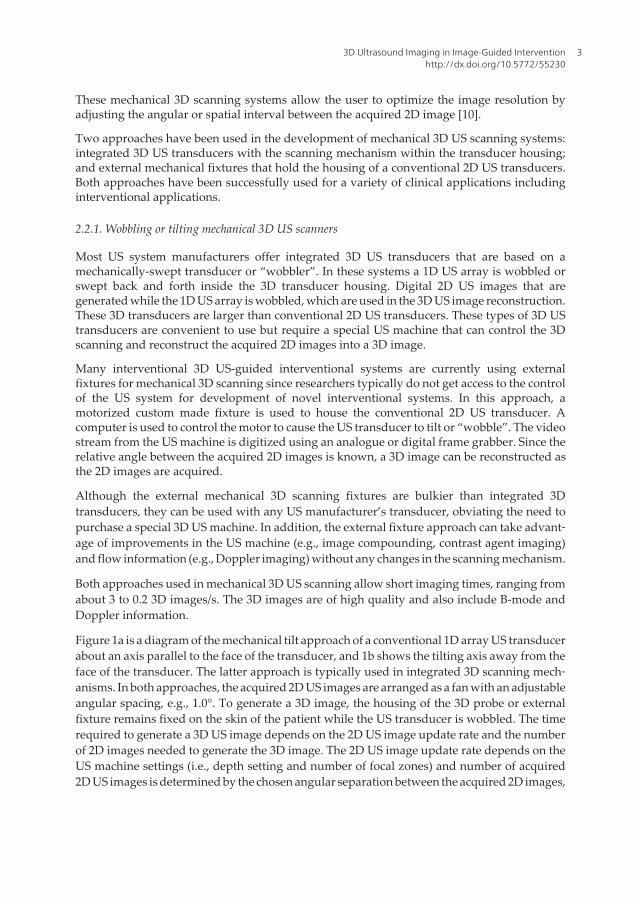
Figure 1a is a diagram of the mechanical tilt approach of a conventional 1D array US transducerabout an axis parallel to the face of the transducer, and 1b shows the tilting axis away from theface of the transducer. The latter approach is typically used in integrated 3D scanning mech‐anisms. In both approaches, the acquired 2D US images are arranged as a fan with an adjustableangular spacing, e.g., 1.0°. To generate a 3D image, the housing of the 3D probe or externalfixture remains fixed on the skin of the patient while the US transducer is wobbled. The timerequired to generate a 3D US image depends on the 2D US image update rate and the numberof 2D images needed to generate the 3D image. The 2D US image update rate depends on theUS machine settings (i.e., depth setting and number of focal zones) and number of acquired2D US images is determined by the chosen angular separation between the acquired 2D images,
3D Ultrasound Imaging in Image-Guided Interventionhttp://dx.doi.org/10.5772/55230
3
and the total scan angle needed to cover the desired anatomy. Typically, these parameters canbe adjusted to optimize scanning time, image quality and the size of the volume imaged[11-16]. The most common integrated 3D transducers using the wobbling technique are usedfor abdominal and obstetrical imaging [17-19].
The 3D image resolution will not be isotropic. The resolution in the 3D US image will degradein the axial direction away from the transducer due to the increasing US beam spread in thelateral and elevational directions of the acquired 2D US images. Since the acquired 2D imagesused to generate a 3D image are arranged as a fan, the distance between the acquired US imagesincreases with increasing axial distance. Increasing axial distances result in decreasing spatialsampling resulting in further loss of spatial resolution in the elevational direction of theacquired 2D US images of the reconstructed 3D image [20].
Figure1
(a)
(c)
(b)
(d)
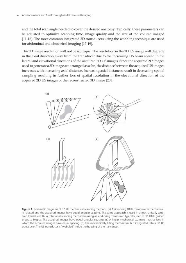
Figure 1. Schematic diagrams of 3D US mechanical scanning methods. (a) A side-firing TRUS transducer is mechanical‐ly rotated and the acquired images have equal angular spacing. The same approach is used in a mechanically-wob‐bled transducer. (b) A rotational scanning mechanism using an end-firing transducer, typically used in 3D TRUS guidedprostate biopsy. The acquired images have equal angular spacing. (c) A linear mechanical scanning mechanism, inwhich the acquired images have equal spacing. (d) The mechanically tilting mechanism, but integrated into a 3D UStransducer. The US transducer is “wobbled” inside the housing of the transducer.
Advancements and Breakthroughs in Ultrasound Imaging4

2.2.2. Linear mechanical 3D scanners
Linear scanners mechanisms use an external motorized fixture to move the conventional 2Dtransducer across the skin of the patient. The 2D transducer can be fixed to be perpendicularto the surface of the skin or at an angle for acquiring Doppler images. The spacing betweenthe acquired 2D images is adjustable but constant during the scan so that the acquired 2Dimages are parallel and uniformly spaced (see Fig. 1c). The velocity of the transducer as it isbeing scanned is adjusted to obtain 2D images with an appropriate spatial interval forgenerating high quality 3D images [10].
The predefined spacing between the acquired 2D US images allows 3D images to be recon‐structed while the 2D US images are being acquired. In the direction parallel to the acquired2D US images the resolution of the reconstructed 3D US image will be the same as the original2D US images. However, in the direction of the 3D scanning, the resolution of the reconstructed3D image will be equal (if spatial sampling is appropriate) to the elevational resolution of theacquired 2D US images. Thus, the resolution of the 3D US image will be poorest in the 3Dscanning direction due to greater spread of the US beam in the elevational direction [21].
This scanning approach is not typically used in interventional applications; however, it hasbeen successfully implemented in many vascular B-mode and Doppler imaging applications,particularly of for carotid arteries [11, 22-30] and tumor vascularization [25, 31-33].
2.2.3. Endo-cavity rotational 3D scanners
The endo-cavity rotational 3D scanning approach has been used extensively in 3D US-guidedprostate interventional procedures. In this approach an external fixture or internal mechanismis used to rotate an endo-cavity transducer (e.g., a transrectal ultrasound (TRUS) probe, seeFig. 1b) about its long axis. Endo-cavity transducers using an end-firing approach are typicallyused for prostate biopsy. When these types of conventional transducers are rotated by themotorized fixture, the set of acquired 2D images will be arranged as a fan (Fig. 1b), intersectingin the center of the 3D US image, resulting in an image as shown in Fig. 2. To obtain a 3D imageof the prostate as in Fig. 2, an end-firing transducer is typically rotated by 180° [16].
Endo-cavity transducers using a side-firing 1D array are typically used in prostate brachy‐therapy, cryotherapy and focal therapy. When using these types of conventional transducers,the acquired images will also be arranged as a fan, but intersect at the axis of rotation of thetransducer (see Fig. 1a). The side-firing transducer is typically rotated from 80° to 110° to obtaina 3D TRUS image of the prostate [16, 34, 35]. Figure 2 shows that endo-cavity scanningtransducer used to image the prostate for 3D US-guided therapy [6, 9, 11, 25, 34, 36-39]
For scanning systems used for 3D US-guided prostate biopsy, the end-firing transducer isrotated by at least 180° about a fixed axis that perpendicularly bisects the transducer array. Inthis approach, the resolution of the 3D image will not be isotropic. Since the spatial samplingis highest near the rotation axis of the transducer and the poorest away from the axis of rotationof the transducer, thus the resolution of the 3D US image will degrade as the distance from therotational axis of the transducer is increased. In addition, the axial and elevational resolutionwill decrease as the distance from the transducer is increased, as discussed above. The
3D Ultrasound Imaging in Image-Guided Interventionhttp://dx.doi.org/10.5772/55230
5
combination of these effects will result in a 3D US image resolution that is best near thetransducer and the rotational axis, while being poorest away from the transducer and rota‐tional axis.
3D rotational scanning with an end-firing transducer is most sensitive to the motion of thetransducer and patient since the axis of rotation is in the center of the 3D US image. Any motionduring the 3D scan will cause a mismatch in the acquired 2D US images, resulting in artifactsin the center of the 3D US image. Artifacts in the center of the 3D US image will also occur ifthe axis of rotation is not accurately known; however, proper calibrations can remove thissource of potential error. Thus, for interventional applications such as 3D US-guided prostatebiopsy or brachytherapy, the rotational scanning mechanism is typically supported by astabilization apparatus [16, 34, 40].
(a) (b)
)
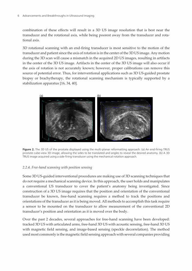
Figure 2. The 3D US of the prostate displayed using the multi-planar reformatting approach: (a) An end-firing TRUSprostate cube-view 3D image, allowing the sides to be translated and angles to reveal the desired anatomy. (b) A 3DTRUS image acquired using a side-firing transducer using the mechanical rotation approach.
2.2.4. Free-hand scanning with position sensing
Some 3D US-guided interventional procedures are making use of 3D scanning techniques thatdo not require a mechanical scanning device. In this approach, the user holds and manipulatesa conventional US transducer to cover the patient’s anatomy being investigated. Sinceconstruction of a 3D US image requires that the position and orientation of the conventionaltransducer be known, free-hand scanning requires a method to track the positions andorientations of the transducer as it is being moved. All methods to accomplish this task requirea sensor to be mounted on the transducer to allow measurement of the conventional 2Dtransducer’s position and orientation as it is moved over the body.
Over the past 2 decades, several approaches for free-hand scanning have been developed:tracked 3D US with articulated arms, free-hand 3D US with acoustic sensing, free-hand 3D USwith magnetic field sensing, and image-based sensing (speckle decorrelation). The methodused most commonly is the magnetic field sensing approach with several companies providing
Advancements and Breakthroughs in Ultrasound Imaging6
the sensing technology: Ascension – Bird sensor [3] Polhemus – Fastrack sensor [41] andNorthern Digital – Aurora sensor [4].
The most successful free-hand 3D US scanning approach used in interventional proceduresmakes use of magnetic field sensors, as well as applications such as echocardiography,obstetrics, and vascular imaging [3, 4, 41-51]. To track the transducer during generation of a3D US image, a small receiver is mounted on the transducer containing three orthogonal coilsallowing six-degrees-of-freedom sensing. The small receiver mounted on the transducermeasures the strength of the magnetic field in three orthogonal directions, which is generatedby a time-varying 3D magnetic field transmitter placed near the patient. The position andorientation of the transducer is calculated by continuously measuring the strength of the threecomponents of the local magnetic field.
Since magnetic field sensors are small and unobtrusive devices, they allow the transducer tobe tracked without the need for bulky mechanical devices, and without the need to keep a clearline of sight as required by optical tracking methods. Since magnetic field sensors are sensitiveto electromagnetic interference or ferrous (or highly conductive) metals located nearby,geometric tracking errors can occur leading to distortions in the 3D US image. Thus, metalbeds used in procedures, or surgical rooms can cause significant distortions. However, modernmagnetic field sensors have been produced to be less susceptible to these sources of error,particularly ones that use a magnetic transmitter placed between the bed and the patient.
3. 3D Ultrasound-guided focal liver ablation
3.1. Clinical problem
Hepatocellular carcinoma (HCC) is the fifth most common diagnosed malignancy and thethird most frequent cause of cancer related deaths worldwide [52]. Incidence is particularlyhigh in Asia and sub-Saharan Africa due to the large incidence of hepatitis B and C, both ofwhich are complicated by hepatic cirrhosis, which is the greatest risk factor for HCC. Recently,increasing trends in HCC have been reported from several Western countries [53]. Further‐more, the liver is the second most common site of metastatic cancer arising in other organs.
When feasible, surgical resection or liver transplant is the accepted standard therapeuticapproach, and currently has the highest success rate of all treatment methods for primary andmetastatic liver cancer. Unfortunately, only 15% of patients are candidates for surgery [54,55]. Patients who do not qualify for surgery usually are offered other therapeutic solutionssuch as chemotherapy and radiotherapy, but unfortunately have variable limited success rates.
Minimally invasive percutaneous techniques, such as radio-frequency (RF) and microwave(MW) ablation of malignant tissue in the liver is a rapidly expanding research field and treat‐ment tool for those patients who are not candidates for surgical resection or transplant. In somecases this acts as a bridge to liver transplantation [54, 56]. Due to low complications rates andshorter recovery times, the indications for these minimally invasive procedures are constantlyincreasing. However, these methods have a higher local recurrence rate than surgical resec‐tion, mostly due to insufficient or inaccurate local ablation of cancerous cells [56, 57].
3D Ultrasound Imaging in Image-Guided Interventionhttp://dx.doi.org/10.5772/55230
7
Microwave energy-induced tissue heating by near-field probes is emerging as a commonthermal treatment of liver tumors [58]. Application of MW for tumor ablation has multipleadvantages over other techniques, including higher treatment temperatures and the ability tocreate larger uniformly shaped ablation zones in shorter time periods. However, the accurateplacement of the probe is critical in achieving the predicted treatment goal [59]. The currentstandard of care uses CT images for planning and 2D US image guidance for intra-operativeguidance of the ablation probe(s) into the target lesion. However, this approach suffers fromseveral disadvantages, such as: (1) 2D US imaging requires physicians to mentally integratemany 2D images to form an impression of the anatomy and pathology, leading to morevariability in guidance during interventional procedures; (2) 2D US does not permit theviewing of planes parallel to the skin, (3) liver deformation and motion artifact due to breathingreduces targeting accuracy, (4) 2D US-based for measurement of tumor volume needed for thetreatment plan is variable and at times inaccurate, and (5) the detection and tracking of theneedle delivering the thermal energy in the liver is crucial for accurate placement of the needlerelative to the tumor, but can be difficult using 2D US. 3D US imaging of the liver and targetmay help to overcome these disadvantages resulting in improved accuracy of probe placementand improved ablation of the lesion.
The use of 3D US-guidance for focal liver tumor ablation is based on the fact that the use of3D US will show the features of liver masses and the hepatic vasculature more clearly, allowguidance of the ablation probes to the target more accurately, and allow more accuratemonitoring of the ablation zone during the procedure and at follow up.
3.2. 3D US Scanner for focal liver tumor ablation
We have developed 3D US guidance systems for improving cancer diagnosis and treatmentby introducing hardware and software innovations [21, 60-64]. Our previous efforts have beenextended to the development of a 3D US-guidance system for treating HCC. Specializedhardware and software tools are used that allow 3D acquisition of 3D US images, real-timeregistration of the pre-operative CT to intra-operative 3D US images, and tracking of theablation probes during insertion into the target. This is accomplished by registering previouslyacquired contrast CT images that show the location of the target lesion to near real-time 3DUS images, plus providing visualization and guidance tools to guide the procedure.
The 3D US scanning system consists of: a hand-held electro-mechanical motor/encoder assem‐bly to move a conventional 2D US imaging transducer in a fan shaped, linear or hybrid motionto a maximum angular limit of 60 degrees and/or 30 mm linear extent to acquire a series of 2D USimages; and, a PC equipped with a digital frame grabber and software components to control themotor assembly, acquire 2D images, reconstruct them in 3D, and visualize them in 3D.
3.2.1. Mechanical design
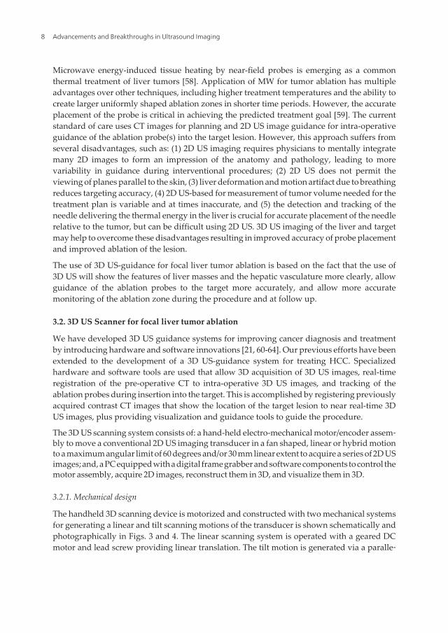
The handheld 3D scanning device is motorized and constructed with two mechanical systemsfor generating a linear and tilt scanning motions of the transducer is shown schematically andphotographically in Figs. 3 and 4. The linear scanning system is operated with a geared DCmotor and lead screw providing linear translation. The tilt motion is generated via a paralle‐
Advancements and Breakthroughs in Ultrasound Imaging8
logram linkage, which is mounted on the carriage of the linear slide. A second geared DC
motor is used to generate the tilt motion, allowing for independent control of the two systems.
Figure 3. Schematic diagram of the hybrid 3D US scanner for used in the focal liver ablation procedure. The diagramshows the start and end positions of the hybrid (linear and tilt) scan.
3D Ultrasound Imaging in Image-Guided Interventionhttp://dx.doi.org/10.5772/55230
9
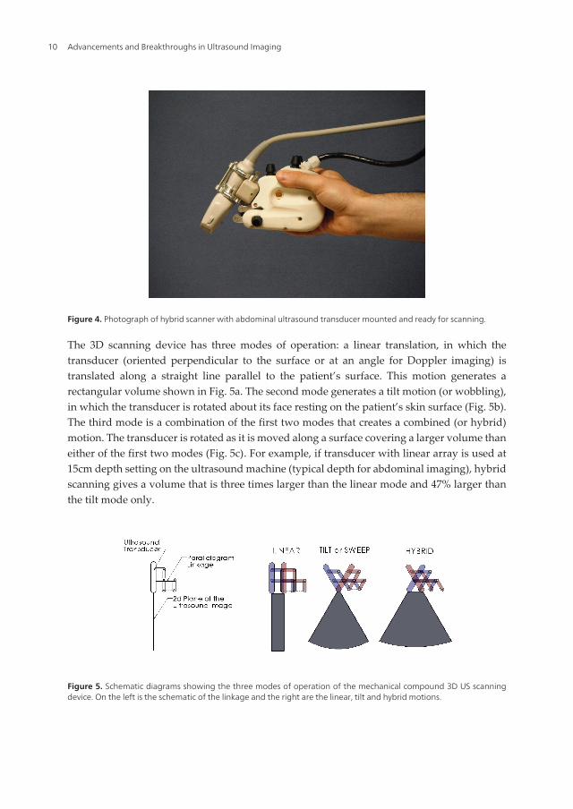
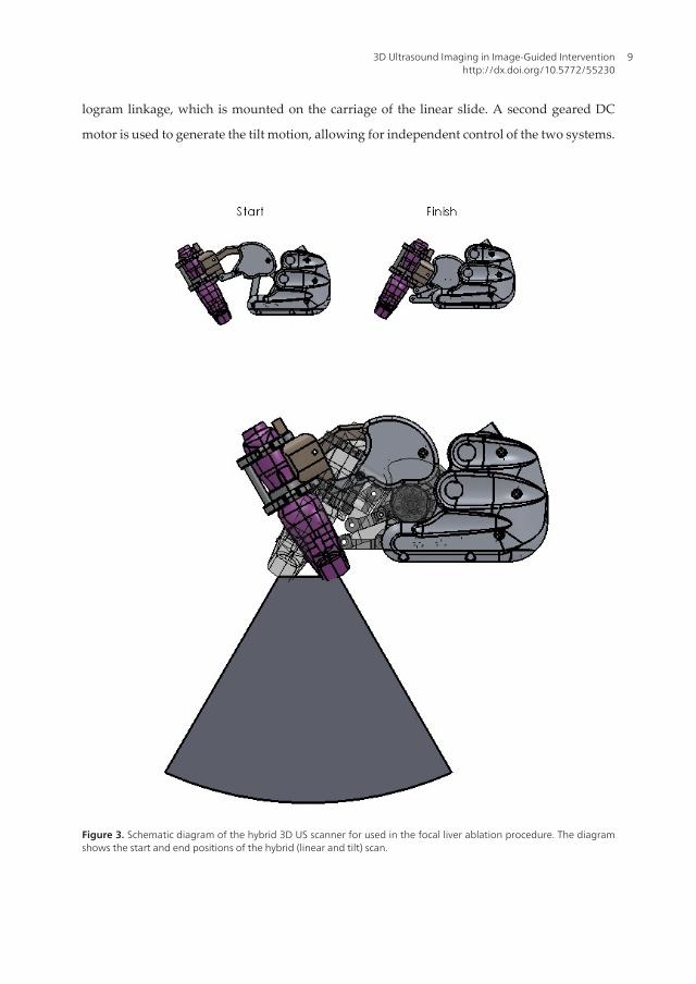
Figure 4. Photograph of hybrid scanner with abdominal ultrasound transducer mounted and ready for scanning.
The 3D scanning device has three modes of operation: a linear translation, in which thetransducer (oriented perpendicular to the surface or at an angle for Doppler imaging) istranslated along a straight line parallel to the patient’s surface. This motion generates arectangular volume shown in Fig. 5a. The second mode generates a tilt motion (or wobbling),in which the transducer is rotated about its face resting on the patient’s skin surface (Fig. 5b).The third mode is a combination of the first two modes that creates a combined (or hybrid)motion. The transducer is rotated as it is moved along a surface covering a larger volume thaneither of the first two modes (Fig. 5c). For example, if transducer with linear array is used at15cm depth setting on the ultrasound machine (typical depth for abdominal imaging), hybridscanning gives a volume that is three times larger than the linear mode and 47% larger thanthe tilt mode only.
Figure 5. Schematic diagrams showing the three modes of operation of the mechanical compound 3D US scanningdevice. On the left is the schematic of the linkage and the right are the linear, tilt and hybrid motions.
Advancements and Breakthroughs in Ultrasound Imaging10

The 3D scanning system parameters can be set by the user: Scanning mode: Three differentmodes of linear, tilt and combined (or hybrid, a combination of both linear and tilt imagingmodes to maximize the field-of-view) are available depending on the anatomy of body partsbeing scanned and the image requirements. Scan Extent: Maximum extent of linear translation(typically 2.5 cm) or tilt angle (typically 60 deg) can be set individually to the extremes values.Scan Spacing: Elevational linear and angular spacing can be set to optimize the trade-offbetween the scanning time and the scan spacing. Frame-Rate: The rate at which images aredigitized by the frame grabber is set (typically 15 frames/s). Scanning Depth: Maximumscanning depth can be set prior to each scan for accurate reconstruction of the volumes.
3.2.2. Validation methods
Since the hybrid scanning mode involves coordination between two acquisition methods, itwas tested in terms of accuracy of 3D image generation. We used two custom made phantomswith known geometry. The validation experiments where performed using the handheld 3DUS scanning device in hybrid scanning mode using a two-dimensional conventional curvedarray ultrasound transducer used for abdominal applications (Toshiba, PVT-375BT).
Geometrical Error in 3D reconstruction: This test was designed to measure the accuracy of the3D reconstruction of the 3D hybrid scanner in three directions. The test phantom was made ofa grid of known dimensions made with 0.1 mm thick nylon monofilament threads wrappedaround an accurately machined frame to form a 4-layer grid. Each layer was slightly shiftedfrom the layer above to avoid acoustic shadowing. The distance between any two layers was1cm. The phantom was submerged in a 15% glycerol solution [61] and imaged at differentdepth settings. The acquired 3D US images were then viewed and analyzed by measuring thedistances between the images of the monofilaments and comparing them to the expectedvalues.
(a) (b)
)
Figure 6. (a) Photograph of the 3D monofilament thread grid, which was used to validate the 3D reconstruction ofthe ultrasound image. (b) The 3D ultrasound image of the phantom, showing the grid of threads.
Error in 3D volume measurements: In the second test, we assessed the accuracy in measuringvolumes using our system. For this experiment, several spherical phantoms with different sizeswere made of tissue mimicking agar [65]. The volume of each of these spherical phantoms wasmeasured prior to embedding them in a cube of tissue mimicking agar phantom. The spherical
3D Ultrasound Imaging in Image-Guided Interventionhttp://dx.doi.org/10.5772/55230
11
phantoms were then imaged with our hybrid scanner, viewed in the 3D visualization software,and manually segmented. The volume of spherical structures were calculated and comparedwith the expected values.
3.2.3. Validation results
Testing the 3D hybrid scanner with the 3D thread phantom showed that mean error in themeasured values of the distances in the X, Y and Z directions were 3.6%, 2.5% and 5.7%respectively. A one-sample t-test was performed to compare the measured distance valueswith the known distance value of 1cm, showed there was no statistical significant differencebetween the measured values and expected values between the threads.
Validation of volume measurements using the hybrid scanner were carried out by imaging atissue mimicking agar sphere with a volume of 10 cm3 embedded in a block of tissue mimickingagar phantom. The measurements were performed at two different depth settings on theultrasound machine (10 and 15 cm). The mean errors of the volume measurement were 5.7%and 4.4% for the 10cm and 15cm depth settings respectively, demonstrating that the hybridscanner can be used to make sufficiently accurate volumetric measurements.
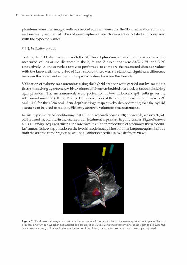
In-vivo experiments: After obtaining institutional research board (IRB) approvals, we investigat‐ed the use of the scanner in thermal ablation treatment of primary hepatic tumors. Figure 7 showsa 3D US image acquired during the microwave ablation procedure of a primary (hepatocellu‐lar) tumor. It shows application of the hybrid mode in acquiring volumes large enough to includeboth the ablated tumor region as well as all ablation needles in two different views.
Figure 7. 3D ultrasound image of a primary (hepatocellular) tumor with two microwave applicators in place. The ap‐plicators and tumor have been segmented and displayed in 3D allowing the interventional radiologist to examine theplacement accuracy of the applicators in the tumor. In addition, the ablation zone has also been superimposed.
Advancements and Breakthroughs in Ultrasound Imaging12
4. 3D ultrasound guided prostate biopsy
4.1. The clinical problem
Prostate Cancer (PCa) is the most commonly diagnosed malignancy in men, and is found atautopsy in 30% of men at age 50, 40% at age 60, and almost 90% at age 90 [66, 67]. Worldwide,it is the second leading cause of death due to cancer in men, accounting for between 2.1% and15.2% of all cancer deaths [68, 69]. Symptoms PCa are generally absent until extensive localgrowth or metastases develop. When diagnosed at an early stage, the disease is curable [70,71], and even at later stages treatment can be effective [72]; however, once the tumor hasextended beyond the prostate, the risk of metastases and locally aggressive cancer increases.Clearly, early diagnosis, accurate staging of prostate cancer, and appropriate therapies arecritical to the patient’s well-being.
In managing patients with possible PCa, the challenges facing physicians are to: (a) diagnoseclinically relevant cancers at a curable stage; (b) stage the disease accurately; (c) apply appro‐priate therapy accurately to optimize destruction of cancer cells while preserving normaltissues and function; and (d) follow patients to assess side effects and therapy effectiveness.This section focuses on improving early PCa diagnosis and staging with the use of 3Dultrasound-guided prostate biopsy.
Since not all cancers are palpable by digital rectal exam (DRE), PCa diagnosis is establishedby histological examination of prostate tissue obtained most commonly by trans-rectalultrasound (TRUS)-guided biopsy. Prostate needle biopsy is the only definitive diagnosticmodality capable of confirming malignancy, and is now always performed with TRUSguidance.
Since many small tumors are not detected by TRUS or DRE, biopsy samples are obtained frompredetermined regions of the prostate known to have a high probability of harboring cancer.These are typically in the peripheral zone (PZ), which harbors 80% of all PCs and a higherproportion of clinically significant ones, and close to the capsule, as most cancers are thoughtto start within 5mm of the prostate capsule. Most centers are now taking 8-12 cores or more aspart of their routine assessment [73-76].
TRUS biopsies are now performed with a thin, 18-gauge needle mounted on a spring-loadedgun connected to the TRUS probe, forcing the needle to stay in the imaging plane. Each coreis separately identified as to the prostate region from which it was drawn, so that the pathol‐ogist can report the extent and grade of the cancer within each region.
Since prostate volume sampled by the biopsy is small, and PCa is often multi-focal, involvingonly a small volume of the prostate in the early stages of the disease [77, 78], the probabilityfor obtaining a sample of the tumour on biopsy is small. Thus, a negative biopsy may be, infact, false, and the patient may be harbouring cancer at an early and curable stage. Variousreports have shown that the false negative rate ranges from 10% to 25% [73, 74]. Since canceris still present in 1/10 to 1/4 of patients with a negative first biopsy, the current biopsy procedureis still suboptimal [74, 79]. Clearly, an improved procedure with improved planning andrecording of biopsy locations is necessary to resolve these issues.
3D Ultrasound Imaging in Image-Guided Interventionhttp://dx.doi.org/10.5772/55230
13
Due to the increasing number of younger men with early and potentially curable PCa under‐going repeated prostate biopsy, it is therefore vital not to re-biopsy the same area if the originalbiopsy was negative, and it is particularly vital to re-biopsy the same area if a possible abnormalarea was detected on first biopsy as ASAP [80]. Thus, the locations of the cores obtained fromthe prostate must be known accurately to help guide the physician during the repeat biopsy[81, 82], to help in correlating any imaging evidence of the disease, and to provide improvedplanning for subsequent therapy.
4.2. Multi-modality directed prostate biopsy
A variety of imaging techniques and molecular imaging probes are being investigated toimprove early detection of PCa. Different magnetic resonance imaging (MRI) techniques havebeen evaluated using body and endo-rectal coils, contrast enhancement, and different pulsesequences [83-85] resulting in disease detection sensitivity and specificity of 80-88% and75-95%, respectively [84, 86, 87]. Positron emission tomography (PET) (combined with CT orMRI) is used to detect early disease, with the newer PET imaging probes proving to be themore promising [88-90]. Although progress has been made with improved PET and MRItechniques, they do not yet have ideal specificity or sufficient accuracy to assess the grade ofthe cancer; thus a biopsy of suspicious lesions on MRI or PET is required to provide a definitivediagnosis and grade of the disease. Systems have been developed to perform biopsies in theMRI suite; however, the cost of the equipment and prolonged use of the MRI is extremelyexpensive and likely prohibitive given the large number of patients requiring biopsy. Un‐fortunately, conventional 2D TRUS guidance of the biopsy procedure limits the physician’sability to target locations identified as suspicious on other modalities.
As we currently do not have a highly sensitive and specific imaging test for local staging ofPCa, there is a growing belief that the optimal method to guide prostate biopsy will involvenot just one, but a combination of imaging modalities. 3D TRUS imaging combined withfunctional or molecular imaging from another imaging modality such as radiopharmaceuticalimaging (PET, SPECT), or magnetic resonance imaging (MRS, MRI) may provide the bestapproach for guiding prostate biopsy.
4.3. 3D TRUS-guided prostate biopsy system
Since ultrasound imaging is the clinical standard for image-guided biopsy of the prostate, wehave developed a 3D TRUS-based navigation system that provides a reproducible record ofthe 3D locations of the biopsy targets throughout the procedure and allows fusion with MRimages with identified lesions for targeting.
The system we have developed is a mechanical 3D biopsy system that maintains the proceduralworkflow, minimizing costs and physician retraining. This mechanical system has 4 degrees-of-freedom (DOF) and has an adaptable cradle that supports commercially available end-firingTRUS transducers used for prostate biopsy [16]. It also allows real time tracking and recordingof the 3D position and orientation of the biopsy needle as the physician manipulates the TRUStransducer. The following describes the components of the system, including hardware,
Advancements and Breakthroughs in Ultrasound Imaging14
modeling and segmentation algorithms, and system validation using a multi-modal US/CTprostate phantom.
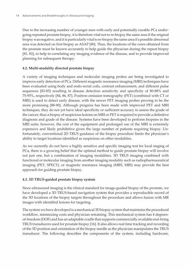
Our approach involves the use of a device composed of two mechanisms shown as a schematicin Figure 8. The system is composed of an articulated multi-jointed stabilizer and a transducertracking mechanism.
Figure 8. A schematic diagram of the mechanical tracker, which supports the TRUS transducer and attached cradle.This configuration constrains the TRUS probe motion to three degrees-of-freedom and one degree of translationalong the axis of the probe. The system is mounted at the base of a stabilizer while the linkage allows the TRUS trans‐ducer to be manually manipulated about a remote center of motion (RCM), which is at the center of the ultrasoundtransducer tip.
The end-firing TRUS transducer with the biopsy needle guide in place is mounted to themechanical tracking mechanism in a manner where the US probe is free to rotate around itslongitudinal axis (Fig. 8). The tracking assembly is attached to a stabilizer, which is mountedon a free-standing cart. Thus, the physician can manipulate the tracking mechanism freely,insert the transducer through the anus, and rotate the transducer in order to acquire a 3D imageof the prostate. The tracking linkage contains angle-sensing encoders mounted to each joint inorder to transmit to the computer the angles between the arms. This arrangement allows thecomputer to determine the relative position of the transducer as it is being manipulated. Sincethe biopsy gun is mounted onto the transducer and its position relative to the transducer iscalibrated, the needle location can be calculated.
The mechanical tracking device is a spherical linkage assembly, in which the axis of the jointsconverge to a common point on the remote center of motion (RCM). The RCM design mini‐mizes targeting errors within the prostate. As the TRUS transducer is constrained through astationary point, the physician’s movements are replicated at a scaled down rate (minifiedthrough the RCM), minimizing changes in morphology and dislocation of the prostate. Inaddition, the RCM enables a precision equivalent to that of robotic assisted machines. Thus,
3D Ultrasound Imaging in Image-Guided Interventionhttp://dx.doi.org/10.5772/55230
15
the system improves the physician’s ability to accurately biopsy a point of interest within thepatient’s prostate.
4.4. Prostate biopsy procedure
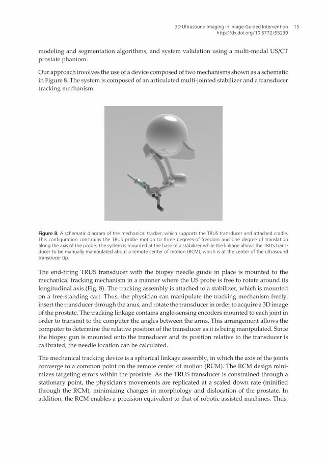
To perform a 3D US-guided prostate biopsy, the end-firing US transducer is mounted onto thetracking assembly such that the tip of the probe is initially set to the RCM point of the trackerlinkage. The physician inserts the TRUS transducer into the patient’s rectum and aligns theprostate to the center of the 2D TRUS image. A 3D image of the prostate is then acquired byrotating the transducer 180 degrees about its longitudinal axis (Fig. 1b) [91]. A graphical modelof the prostate is then generated by a semi-automatic 3D segmentation algorithm [61, 92-94].After the prostate model has been constructed, the physician can then manipulate the 3D imageon the computer screen and select locations to biopsy. After all of the biopsy targets have beenselected, the system then displays the 3D needle guidance interface (Fig. 9), which facilitatesthe systematic targeting of each biopsy location previously selected. Other images or infor‐mation (e.g., MRI or PET/CT images), if available, are registered to the 3D TRUS image anddisplayed as an overlay on the computer screen (Fig. 10).
Figure 9. The 3D US-guided prostate biopsy system interface is composed of 4 windows: (top left) the 3D TRUS imagedynamically sliced to match the real-time TRUS probe 3D orientation, (bottom left) the live 2D TRUS video stream,(right side) and the 3D location of the biopsy core is displayed within the 3D prostate models. The targeting ring in thebottom right window shows all the possible needle paths that intersect the preplanned target by rotating the TRUSabout its long axis. This allows the physician to move the TRUS probe to the target (highlighted by the red dot) in theshortest possible distance. The segmented tumor to be targeted is outlined and rendered in red.
Advancements and Breakthroughs in Ultrasound Imaging16
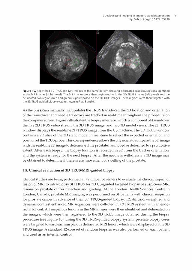
Figure 10. Registered 3D TRUS and MRI images of the same patient showing delineated suspicious lesions identifiedin the MR images (right panel). The MR images were then registered with the 3D TRUS images (left panel) and thedelineated two regions (red and green) superimposed on the 3D TRUS images. These regions were then targeted withthe 3D TRUS-guided biopsy system shown in Figs. 8 and 9.
As the physician manually manipulates the TRUS transducer, the 3D location and orientationof the transducer and needle trajectory are tracked in real-time throughout the procedure onthe computer screen. Figure 9 illustrates the biopsy interface, which is composed of 4 windows:the live 2D TRUS video stream, the 3D TRUS image, and two 3D model views. The 2D TRUSwindow displays the real-time 2D TRUS image from the US machine. The 3D TRUS windowcontains a 2D slice of the 3D static model in real-time to reflect the expected orientation andposition of the TRUS probe. This correspondence allows the physician to compare the 3D imagewith the real-time 2D image to determine if the prostate has moved or deformed to a prohibitiveextent. After each biopsy, the biopsy location is recorded in 3D from the tracker orientation,and the system is ready for the next biopsy. After the needle is withdrawn, a 3D image maybe obtained to determine if there is any movement or swelling of the prostate.
4.5. Clinical evaluation of 3D TRUS/MRI-guided biopsy
Clinical studies are being performed at a number of centers to evaluate the clinical impact offusion of MRI to intra-biopsy 3D TRUS for 3D US-guided targeted biopsy of suspicious MRIlesions on prostate cancer detection and grading. At the London Health Sciences Centre inLondon, Canada, prostate MR imaging was performed on 31 patients with clinical suspicionfor prostate cancer in advance of their 3D TRUS-guided biopsy. T2, diffusion-weighted anddynamic-contrast enhanced MR sequences were collected in a 3T MRI system with an endo-rectal RF coil. All suspicious lesions in the MR images were then identified and delineated onthe images, which were then registered to the 3D TRUS image obtained during the biopsyprocedure (see Figure 10). Using the 3D TRUS-guided biopsy system, prostate biopsy coreswere targeted toward each suspicious delineated MRI lesion, which were displayed on the 3DTRUS image. A standard 12-core set of random biopsies was also performed on each patientand used as an internal control.
3D Ultrasound Imaging in Image-Guided Interventionhttp://dx.doi.org/10.5772/55230
17
The results of this study showed that MRI-3D TRUS fusion was successfully performed andthe targeted biopsy needle cores had a significantly higher rates of prostate malignancy (30.0%)compared to random, sextant cores (10.0%). In total, prostate cancer was biopsy confirmed in11 patients; however, only 7 of these patients had abnormal MRI findings (even in retrospectiveanalysis) and were sampled with targeted MRI-3D TRUS fusion. Random sampling detectedthe remaining four patients. A significantly higher percentage of the targeted biopsy cores(47+/-26%) contained cancer compared to the randomly sampled cores (28+/-26%), and for 3patients, the MRI-targeted cores detected a higher Gleason cancer grade than the random cores,modifying potential treatment modalities. This study showed that MRI-3D TRUS fusion allowsfor superior sampling of prostate cancer visible on MRI. This technology may benefit bothcancer detection and accurate malignancy grading for appropriate therapeutic management;however, further testing is needed to establish the full utility of this technology.
5. Conclusions
Clinical evaluation of the mechanical tracking systems for use in 3D ultrasound guidance forfocal liver ablation and prostate biopsy have been found to be easy to use. The tracker permitsmanual motions identical to the current conventional procedure, where restricted movementsare produced by the US probe in the patient’s rectum.
Reconstruction of 3D TRUS images using the hybrid approach for focal liver ablation, androtational approach for prostate biopsy can produce accurate 3D images without significantvisible discontinuity or artefacts. Volume calculations from the 3D TRUS image have shownthat the 3D US systems can generate accurate volume measurements.
The patient studies have demonstrated that it is possible to minimize the effects of liver andprostate motion through a variety of mechanical and software mechanisms. However,improved solutions, which correct any patient motion automatically are still needed. It is notpossible to control all patient/organ motion during the procedures, particularly if the patientmoves during the prostate biopsy procedure after the firing of the prostate biopsy needle. Toovercome this problem, a software module would have to be developed to inform the physicianthat the prostate has moved and then correct for the motion and deformation. This task mustbe done quickly, possibly in real-time, using an implementation of the software in a graphicalprocessing unit (GPU).
Acknowledgements
The authors gratefully acknowledge the financial support of the Canadian Institutes of HealthResearch, the Ontario Institute for Cancer Research, the Ontario Research Fund, the NationalScience and Engineering Research Council, and the Canada Research Chair program.
Advancements and Breakthroughs in Ultrasound Imaging18
Author details
Aaron Fenster1,2,3, Jeff Bax1,2, Hamid Neshat1,2, Nirmal Kakani3 and Cesare Romagnoli3
1 Robarts Research Institute, University of Western Ontario, London, Canada
2 Biomedical Engineering Department, University of Western Ontario, London, Canada
3 Department of Medical Imaging, University of Western Ontario, London, Canada
References
[1] Elliott ST. Volume ultrasound: the next big thing? Br J Radiol. 2008;81(961):8-9.
[2] Downey DB, Fenster A, Williams JC. Clinical utility of three-dimensional US. Radio‐graphics. 2000;20(2):559-71.
[3] Boctor EM, Choti MA, Burdette EC, Webster Iii RJ. Three-dimensional ultrasound-guided robotic needle placement: an experimental evaluation. Int J Med Robot.2008;4(2):180-91.
[4] Hummel J, Figl M, Bax M, Bergmann H, Birkfellner W. 2D/3D registration of endo‐scopic ultrasound to CT volume data. Phys Med Biol. 2008;53(16):4303-16.
[5] Carson PL, Fenster A. Anniversary paper: evolution of ultrasound physics and therole of medical physicists and the AAPM and its journal in that evolution. Med Phys.2009;36(2):411-28.
[6] Wei Z, Wan G, Gardi L, Mills G, Downey D, Fenster A. Robot-assisted 3D-TRUSguided prostate brachytherapy: system integration and validation. Med Phys.2004;31(3):539-48.
[7] Smith WL, Surry K, Mills G, Downey D, Fenster A. Three-dimensional ultrasound-guided core needle breast biopsy. Ultrasound in Med and Bio. 2001;27(8):1025-34.
[8] Chin JL, Downey DB, Onik G, Fenster A. Three-dimensional prostate ultrasound andits application to cryosurgery. Tech Urol. 1996;2(4):187-93.
[9] Chin JL, Downey DB, Mulligan M, Fenster A. Three-dimensional transrectal ultra‐sound guided cryoablation for localized prostate cancer in nonsurgical candidates: afeasibility study and report of early results. J Urol. 1998;159(3):910-4.
[10] Smith WL, Fenster A. Optimum Scan Spacing for Three-Dimensional Ultrasound bySpeckle Statistics. Ultrasound in Medicine and Biology. 2000;26(4):551-62.
[11] Fenster A, Tong S, Sherebrin S, Downey DB, Rankin RN. Three-dimensional ultra‐sound imaging. SPIE Physics of Medical Imaging. 1995;2432:176-84.
3D Ultrasound Imaging in Image-Guided Interventionhttp://dx.doi.org/10.5772/55230
19
[12] Delabays A, Pandian NG, Cao QL, Sugeng L, Marx G, Ludomirski A, et al. Trans‐thoracic real-time three-dimensional echocardiography using a fan-like scanning ap‐proach for data acquisition: methods, strengths, problems, and initial clinicalexperience. Echocardiography. 1995;12(1):49-59.
[13] Downey DB, Nicolle DA, Fenster A. Three-dimensional orbital ultrasonography. CanJ Ophthalmol. 1995;30(7):395-8.
[14] Downey DB, Nicolle DA, Fenster A. Three-dimensional ultrasound of the eye. Ad‐ministrative Radiology Journal. 1995;14:46-50.
[15] Gilja OH, Thune N, Matre K, Hausken T, Odegaard S, Berstad A. In vitro evaluationof three-dimensional ultrasonography in volume estimation of abdominal organs.Ultrasound Med Biol. 1994;20(2):157-65.
[16] Bax J, Cool D, Gardi L, Knight K, Smith D, Montreuil J, et al. Mechanically assisted3D ultrasound guided prostate biopsy system. Med Phys. 2008;35(12):5397-410.
[17] Goncalves L, Nien J, Espinoza J, Kusanovic J, Lee W, Swope B, et al. Two-Dimension‐al (2D) versus three- and four-dimensional (3D/4D) us in obstetrical practice: Doesthe new technology add anything? American Journal of Obstetrics and Gynecology.2005;193(6):S150-S.
[18] Peralta CF, Cavoretto P, Csapo B, Falcon O, Nicolaides KH. Lung and heart volumesby three-dimensional ultrasound in normal fetuses at 12-32 weeks' gestation. Ultra‐sound Obstet Gynecol. 2006;27(2):128-33.
[19] Kurjak A, Miskovic B, Andonotopo W, Stanojevic M, Azumendi G, Vrcic H. Howuseful is 3D and 4D ultrasound in perinatal medicine? J Perinat Med. 2007;35(1):10-27.
[20] Blake CC, Elliot TL, Slomka PJ, Downey DB, Fenster A. Variability and accuracy ofmeasurements of prostate brachytherapy seed position in vitro using three-dimen‐sional ultrasound: an intra- and inter-observer study. Med Phys. 2000;27(12):2788-95.
[21] Fenster A, Downey DB, Cardinal HN. Three-dimensional ultrasound imaging. PhysMed Biol. 2001;46(5):R67-99.
[22] Downey DB, Fenster A. Vascular imaging with a three-dimensional power Dopplersystem. AJR Am J Roentgenol. 1995;165(3):665-8.
[23] Picot PA, Rickey DW, Mitchell R, Rankin RN, Fenster A. Three-dimensional colourDoppler imaging. Ultrasound Med Biol. 1993;19(2):95-104.
[24] Pretorius DH, Nelson TR, Jaffe JS. 3-dimensional sonographic analysis based on colorflow Doppler and gray scale image data: a preliminary report. J Ultrasound Med.1992;11(5):225-32.
[25] Downey DB, Fenster A. Three-dimensional power Doppler detection of prostate can‐cer [letter]. 1995;165(3):741.
Advancements and Breakthroughs in Ultrasound Imaging20
[26] Landry A, Fenster A. Theoretical and experimental quantification of carotid plaquevolume measurements made by 3D ultrasound using test phantoms. Medical Phys‐ics. 2002.
[27] Landry A, Ainsworth C, Blake C, Spence JD, Fenster A. Manual planimetric measure‐ment of carotid plaque volume using three-dimensional ultrasound imaging. Medi‐cal Physics. 2007;34(4):1496-505.
[28] Landry A, Spence JD, Fenster A. Quantification of carotid plaque volume measure‐ments using 3D ultrasound imaging. Ultrasound Med Biol. 2005;31(6):751-62.
[29] Ainsworth CD, Blake CC, Tamayo A, Beletsky V, Fenster A, Spence JD. 3D Ultra‐sound Measurement of Change in Carotid Plaque Volume; A Tool for Rapid Evalua‐tion of New Therapies. Stroke. 2005;35:1904-9.
[30] Krasinski A, Chiu B, Spence JD, Fenster A, Parraga G. Three-dimensional UltrasoundQuantification of Intensive Statin Treatment of Carotid Atherosclerosis. Ultrasoundin Medicine & Biology. 2009;35(11):1763-72.
[31] Bamber JC, Eckersley RJ, Hubregtse P, Bush NL, Bell DS, Crawford DC. Data proc‐essing for 3-D ultrasound visualization of tumour anatomy and blood flow. SPIE.1992;1808:651-63.
[32] Carson PL, Li X, Pallister J, Moskalik A, Rubin JM, Fowlkes JB. Approximate quanti‐fication of detected fractional blood volume and perfusion from 3-D color flow andDoppler power signal imaging. 1993 ultrasonics symposium proceedings. Piscat‐away, NJ: IEEE; 1993. p. 1023-6.
[33] King DL, King DLJ, Shao MY. Evaluation of in vitro measurement accuracy of athree-dimensional ultrasound scanner. J Ultrasound Med. 1991;10(2):77-82.
[34] Tong S, Downey DB, Cardinal HN, Fenster A. A three-dimensional ultrasound pros‐tate imaging system. Ultrasound Med Biol. 1996;22(6):735-46.
[35] Tong S, Cardinal HN, McLoughlin RF, Downey DB, Fenster A. Intra- and inter-ob‐server variability and reliability of prostate volume measurement via two-dimen‐sional and three-dimensional ultrasound imaging. Ultrasound Med Biol. 1998;24(5):673-81.
[36] Downey DB, Chin JL, Fenster A. Three-dimensional US-guided cryosurgery. Radiol‐ogy. 1995;197(P):539.
[37] Chin JL, Downey DB, Elliot TL, Tong S, McLean CA, Fortier M, et al. Three dimen‐sional transrectal ultrasound imaging of the prostate: clinical validation. Can J Urol.1999;6(2):720-6.
[38] Onik GM, Downey DB, Fenster A. Three-dimensional sonographically monitoredcryosurgery in a prostate phantom. J Ultrasound Med. 1996;15(3):267-70.
3D Ultrasound Imaging in Image-Guided Interventionhttp://dx.doi.org/10.5772/55230
21
[39] Wei Z, Gardi L, Downey DB, Fenster A. Oblique needle segmentation and trackingfor 3D TRUS guided prostate brachytherapy. Med Phys. 2005;32(9):2928-41.
[40] Cool D, Sherebrin S, Izawa J, Chin J, Fenster A. Design and evaluation of a 3D trans‐rectal ultrasound prostate biopsy system. Med Phys. 2008;35(10):4695-707.
[41] Treece G, Prager R, Gee A, Berman L. 3D ultrasound measurement of large organvolume. Med Image Anal. 2001;5(1):41-54.
[42] Detmer PR, Bashein G, Hodges T, Beach KW, Filer EP, Burns DH, et al. 3D ultrasonicimage feature localization based on magnetic scanhead tracking: in vitro calibrationand validation. Ultrasound Med Biol. 1994;20(9):923-36.
[43] Hodges TC, Detmer PR, Burns DH, Beach KW, Strandness DEJ. Ultrasonic three-di‐mensional reconstruction: in vitro and in vivo volume and area measurement. Ultra‐sound Med Biol. 1994;20(8):719-29.
[44] Hughes SW, D'Arcy TJ, Maxwell DJ, Chiu W, Milner A, Saunders JE, et al. Volumeestimation from multiplanar 2D ultrasound images using a remote electromagneticposition and orientation sensor. Ultrasound Med Biol. 1996;22(5):561-72.
[45] Leotta DF, Detmer PR, Martin RW. Performance of a miniature magnetic positionsensor for three-dimensional ultrasound imaging. Ultrasound Med Biol. 1997;23(4):597-609.
[46] Gilja OH, Detmer PR, Jong JM, Leotta DF, Li XN, Beach KW, et al. Intragastric distri‐bution and gastric emptying assessed by three-dimensional ultrasonography. Gastro‐enterology. 1997;113(1):38-49.
[47] Nelson TR, Pretorius DH. Visualization of the fetal thoracic skeleton with three-di‐mensional sonography: a preliminary report. AJR Am J Roentgenol. 1995;164(6):1485-8.
[48] Pretorius DH, Nelson TR. Prenatal visualization of cranial sutures and fontanelleswith three-dimensional ultrasonography. J Ultrasound Med. 1994;13(11):871-6.
[49] Raab FH, Blood EB, Steiner TO, Jones HR. Magnetic position and orientation trackingsystem. IEEE Transactions on Aerospace and Electronic systems. 1979;AES-15:709-17.
[50] Riccabona M, Nelson TR, Pretorius DH, Davidson TE. Distance and volume meas‐urement using three-dimensional ultrasonography. J Ultrasound Med. 1995;14(12):881-6.
[51] Hsu PW, Prager RW, Gee AH, Treece GM. Real-time freehand 3D ultrasound calibra‐tion. Ultrasound Med Biol. 2008;34(2):239-51.
[52] Jemal A, Bray F, Center MM, Ferlay J, Ward E, Forman D. Global cancer statistics.CA Cancer J Clin. 2011;61(2):69-90.
Advancements and Breakthroughs in Ultrasound Imaging22
[53] Jemal A, Siegel R, Xu J, Ward E. Cancer statistics, 2010. CA Cancer J Clin. 2010;60(5):277-300.
[54] Solbiati L, Ierace T, Tonolini M, Cova L. Ablation of Liver Metastases: Springer, Ber‐lin; 2004. 311 - 21 p.
[55] El-Serag HB, Marrero JA, Rudolph L, Reddy KR. Diagnosis and treatment of hepato‐cellular carcinoma. Gastroenterology. 2008;134(6):1752-63.
[56] Adam A, Mueller P. Interventional Radiological Treatment of Liver Tumors. Cam‐bridge, UK: Cambridge University Press; 2009.
[57] McKay A, Fradette K, Lipschitz J. Long-term outcomes following hepatic resectionand radiofrequency ablation of colorectal liver metastases. HPB Surg.2009;2009:346863.
[58] Seki T. "Microwave Coagulation Therapy for Liver Tumors", Tumour Ablation, Prin‐ciple and Practice: Springer; 2004. 218 - 27 p.
[59] Haemmerich D, Laeseke PF. Thermal tumour ablation: devices, clinical applicationsand future directions. Int J Hyperthermia. 2005;21(8):755-60.
[60] Cool DW, Gardi L, Romagnoli C, Saikaly M, Izawa JI, Fenster A. Temporal-basedneedle segmentation algorithm for transrectal ultrasound prostate biopsy proce‐dures. Med Phys. 2010;37(4):1660-73.
[61] Wang Y, Cardinal HN, Downey DB, Fenster A. Semiautomatic three-dimensionalsegmentation of the prostate using two-dimensional ultrasound images. Med Phys.2003;30(5):887-97.
[62] Ding M, Cardinal HN, Fenster A. Automatic needle segmentation in three-dimen‐sional ultrasound images using two orthogonal two-dimensional image projections.Med Phys. 2003;30(2):222-34.
[63] Ding M, Fenster A. A real-time biopsy needle segmentation technique using Houghtransform. Med Phys. 2003;30(8):2222-33.
[64] Karnik VV, Fenster A, Bax J, Gardi L, Gyacskov I, Montreuil J, et al. Evaluation ofinter-session 3D-TRUS to 3D-TRUS image registration for repeat prostate biopsies.Med Image Comput Comput Assist Interv. 2010;13(Pt 2):17-25.
[65] Rickey DW, Picot PA, Christopher DA, Fenster A. A wall-less vessel phantom forDoppler ultrasound studies. Ultrasound Med Biol. 1995;21(9):1163-76.
[66] McNeal JE, Bostwick DG, Kindrachuk RA, Redwine EA, Freiha FS, Stamey TA. Pat‐terns of progression in prostate cancer. Lancet. 1986;1(8472):60-3.
[67] Garfinkel L, Mushinski M. Cancer incidence, mortality and survival: trends in fourleading sites. Stat Bull Metrop Insur Co. 1994;75(3):19-27.
3D Ultrasound Imaging in Image-Guided Interventionhttp://dx.doi.org/10.5772/55230
23
[68] Silverberg E, Boring CC, Squires TS. Cancer statistics, 1990 [see comments]. CACanc‐er J Clin. 1990;40:9-26.
[69] Abbas F, Scardino PT. The natural history of clinical prostate carcinoma [editorial;comment]. Cancer. 1997;80(5):827-33.
[70] Shinohara K, Scardino PT, Carter SS, Wheeler TM. Pathologic basis of the sonograph‐ic appearance of the normal and malignant prostate. Urol Clin North Am. 1989;16(4):675-91.
[71] Terris MK, McNeal JE, Stamey TA. Estimation of prostate cancer volume by transrec‐tal ultrasound imaging. J Urol. 1992;147(3 Pt 2):855-7.
[72] Rifkin MD. Ultrasound of the prostate-Imaging in the diagnosis and therapy of pro‐static disease. 2 ed. Ryan JD, Patterson D, DiFrancesco R, editors. Philadelphia, NewYork: Lippincott-Raven Publishers; 1997.
[73] Djavan B, Zlotta AR, Ekane S, Remzi M, Kramer G, Roumeguere T, et al. Is one set ofsextant biopsies enough to rule out prostate Cancer? Influence of transition and totalprostate volumes on prostate cancer yield. Eur Urol. 2000;38(2):218-24.
[74] Djavan B, Remzi M, Schulman CC, Marberger M, Zlotta AR. Repeat prostate biopsy:who, how and when?. a review. Eur Urol. 2002;42(2):93-103.
[75] Matlaga BR, Eskew LA, McCullough DL. Prostate biopsy: indications and technique.J Urol. 2003;169(1):12-9.
[76] Presti JC, Jr., O'Dowd GJ, Miller MC, Mattu R, Veltri RW. Extended peripheral zonebiopsy schemes increase cancer detection rates and minimize variance in prostatespecific antigen and age related cancer rates: results of a community multi-practicestudy. J Urol. 2003;169(1):125-9.
[77] Jemal A, Thomas A, Murray T, Thun M. Cancer statistics, 2002. CA Cancer J Clin.2002;52(1):23-47.
[78] Nelson WG, De Marzo AM, Isaacs WB. Prostate cancer. N Engl J Med. 2003;349(4):366-81.
[79] Park SJ, Miyake H, Hara I, Eto H. Predictors of prostate cancer on repeat transrectalultrasound-guided systematic prostate biopsy. Int J Urol. 2003;10(2):68-71.
[80] Iczkowski KA, Chen HM, Yang XJ, Beach RA. Prostate cancer diagnosed after initialbiopsy with atypical small acinar proliferation suspicious for malignancy is similar tocancer found on initial biopsy. Urology. 2002;60(5):851-4.
[81] Thorson P, Humphrey PA. Minimal adenocarcinoma in prostate needle biopsy tis‐sue. Am J Clin Pathol. 2000;114(6):896-909.
Advancements and Breakthroughs in Ultrasound Imaging24
[82] San Francisco I, DeWolf W, Rosen S, Upton M, Olumi A. Extended prostate needlebiopsy improves concordance of Gleason grading between prostate needle biopsyand radical prostatectomy. Urology. 2003;169:136-40.
[83] Futterer JJ, Heijmink SW, Scheenen TW, Veltman J, Huisman HJ, Vos P, et al. Pros‐tate cancer localization with dynamic contrast-enhanced MR imaging and proton MRspectroscopic imaging. Radiology. 2006;241(2):449-58.
[84] Hricak H, Choyke PL, Eberhardt SC, Leibel SA, Scardino PT. Imaging prostate can‐cer: a multidisciplinary perspective. Radiology. 2007;243(1):28-53.
[85] Manenti G, Carlani M, Mancino S, Colangelo V, Di Roma M, Squillaci E, et al. Diffu‐sion tensor magnetic resonance imaging of prostate cancer. Invest Radiol. 2007;42(6):412-9.
[86] Heijmink SW, Futterer JJ, Hambrock T, Takahashi S, Scheenen TW, Huisman HJ, etal. Prostate cancer: body-array versus endorectal coil MR imaging at 3 T--comparisonof image quality, localization, and staging performance. Radiology. 2007;244(1):184-95.
[87] Morgan VA, Kyriazi S, Ashley SE, DeSouza NM. Evaluation of the potential of diffu‐sion-weighted imaging in prostate cancer detection. Acta Radiol. 2007;48(6):695-703.
[88] Farsad M, Schiavina R, Castellucci P, Nanni C, Corti B, Martorana G, et al. Detectionand localization of prostate cancer: correlation of (11)C-choline PET/CT with histopa‐thologic step-section analysis. J Nucl Med. 2005;46(10):1642-9.
[89] Martorana G, Schiavina R, Corti B, Farsad M, Salizzoni E, Brunocilla E, et al. 11C-choline positron emission tomography/computerized tomography for tumor locali‐zation of primary prostate cancer in comparison with 12-core biopsy. J Urol.2006;176(3):954-60; discussion 60.
[90] Schoder H, Gonen M. Screening for cancer with PET and PET/CT: potential and limi‐tations. J Nucl Med. 2007;48 Suppl 1:4S-18S.
[91] Fenster A, Downey DB, Cardinal HN. Topical Review: Three-dimensional ultra‐sound imaging. Phys Med Biol. 2001;46(5):R67-99.
[92] Ladak HM, Mao F, Wang Y, Downey DB, Steinman DA, Fenster A. Prostate boun‐dary segmentation from 2D ultrasound images. Med Phys. 2000;27(8):1777-88.
[93] Hu N, Downey DB, Fenster A, Ladak HM. Prostate boundary segmentation from 3Dultrasound images. Med Phys. 2003;30(7):1648-59.
[94] Cool D, Downey D, Izawa J, Chin J, Fenster A. 3D prostate model formation fromnon-parallel 2D ultrasound biopsy images. Med Image Anal. 2006;10(6):875-87.
3D Ultrasound Imaging in Image-Guided Interventionhttp://dx.doi.org/10.5772/55230
25

Related Documents