Western Michigan University Western Michigan University ScholarWorks at WMU ScholarWorks at WMU Honors Theses Lee Honors College 4-16-2019 3D Printing Robotic Arm on Linear Rails 3D Printing Robotic Arm on Linear Rails Thomas T. Steele Western Michigan University, [email protected] Follow this and additional works at: https://scholarworks.wmich.edu/honors_theses Part of the Mechanical Engineering Commons Recommended Citation Recommended Citation Steele, Thomas T., "3D Printing Robotic Arm on Linear Rails" (2019). Honors Theses. 3175. https://scholarworks.wmich.edu/honors_theses/3175 This Honors Thesis-Open Access is brought to you for free and open access by the Lee Honors College at ScholarWorks at WMU. It has been accepted for inclusion in Honors Theses by an authorized administrator of ScholarWorks at WMU. For more information, please contact [email protected].

Welcome message from author
This document is posted to help you gain knowledge. Please leave a comment to let me know what you think about it! Share it to your friends and learn new things together.
Transcript
Western Michigan University Western Michigan University
ScholarWorks at WMU ScholarWorks at WMU
Honors Theses Lee Honors College
4-16-2019
3D Printing Robotic Arm on Linear Rails 3D Printing Robotic Arm on Linear Rails
Thomas T. Steele Western Michigan University, [email protected]
Follow this and additional works at: https://scholarworks.wmich.edu/honors_theses
Part of the Mechanical Engineering Commons
Recommended Citation Recommended Citation Steele, Thomas T., "3D Printing Robotic Arm on Linear Rails" (2019). Honors Theses. 3175. https://scholarworks.wmich.edu/honors_theses/3175
This Honors Thesis-Open Access is brought to you for free and open access by the Lee Honors College at ScholarWorks at WMU. It has been accepted for inclusion in Honors Theses by an authorized administrator of ScholarWorks at WMU. For more information, please contact [email protected].
3D Printing Robotic Arm on Linear Rails ME 4790 - Mechanical Engineering Project Planning
Group 31 - Nick Goberville and Trenton Steele Mentor - Dr. Zachary Asher
Spring 2019

Abstract
3D Printing has become the focus of many engineering and manufacturing fields as a source of cheap and versatile production. In 2016, roughly 455,000 3D printing units were shipped worldwide, but by 2020 this number is expected to be 6.7 Million units (Gartner & Gartner, 2016). As 3D printer markets continue to boom, the problems with current 3D printing solutions are being exposed and future solutions are being sought in the use of different materials, varying print mediums, and using different styles of print heads. Our group believes that one of the most limiting factors of current 3D printers is the size of printing beds relative to the size of the printer frame. We believe that this space efficiency problem can be solved with the mounting of a 3D print head on top of a 4 axis robotic arm. This printer and arm assembly have been mounted on a sliding linear rail system. Linear motion in conjunction with the arm allow our project to increase the area of the printing bed as well as allowing for the printing of elongated objects. This project solves space efficiency issues generated by the current generation of 3D printers.
2
Acknowledgements
Our team is grateful to the people who made the results of this project possible. We
understand that their time is valuable and are grateful for both their time and insight spent
helping us to grow as engineers through this project process.
Dr. Zachary Asher - Western Michigan University: Dr. Asher was our mentor for this project,
giving us invaluable oversight and ensuring that a good engineering process was applied
throughout the process of our design.
Matt Burkart - Car Keys Fast Incorporated: Matt is Trenton’s employer and graciously allowed
the use of his shop to house the traditional FDM printer and allowed Inventor Software to be run
on a work PC to assist in the design of the arm.
Joe Burkart - Car Keys Fast Incorporated: Joe oversaw the construction of the FDM printer used
by the team and assisted in trouble shooting with circuitry and printing problems.
WMU Research Grant Donors - Western Michigan University: This project would not have been
possible without the help of the Undergraduate Award for Research and Creative Scholarship
Excellence. This grant money allowed the team to have the available funds to see the project
through to completion.
3

Table of Contents
4
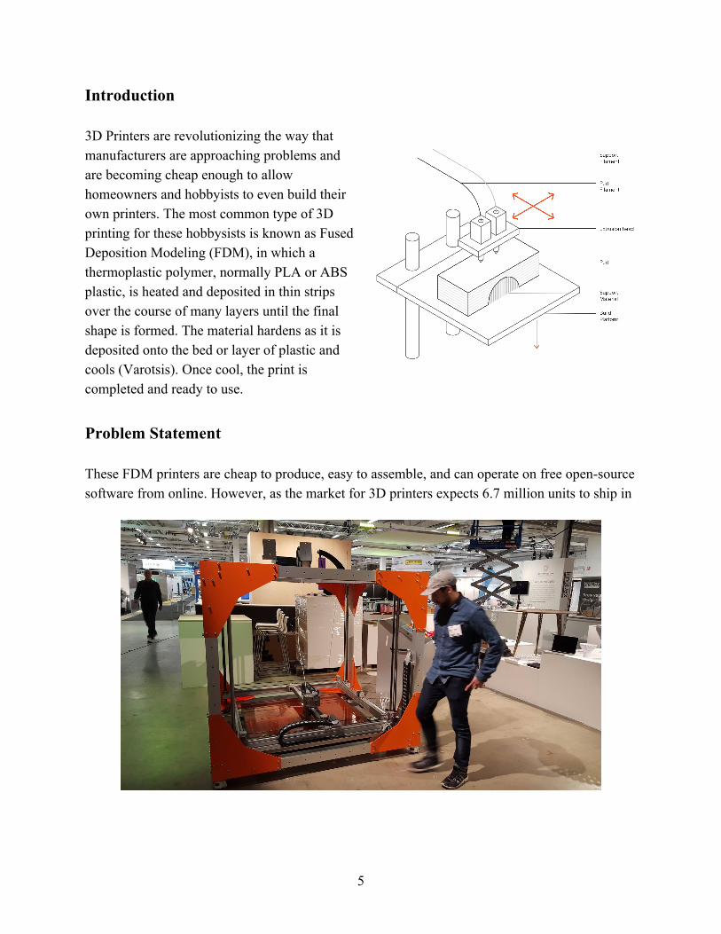
Introduction 3D Printers are revolutionizing the way that manufacturers are approaching problems and are becoming cheap enough to allow homeowners and hobbyists to even build their own printers. The most common type of 3D printing for these hobbysists is known as Fused Deposition Modeling (FDM), in which a thermoplastic polymer, normally PLA or ABS plastic, is heated and deposited in thin strips over the course of many layers until the final shape is formed. The material hardens as it is deposited onto the bed or layer of plastic and cools (Varotsis). Once cool, the print is completed and ready to use.
Problem Statement These FDM printers are cheap to produce, easy to assemble, and can operate on free open-source software from online. However, as the market for 3D printers expects 6.7 million units to ship in
5
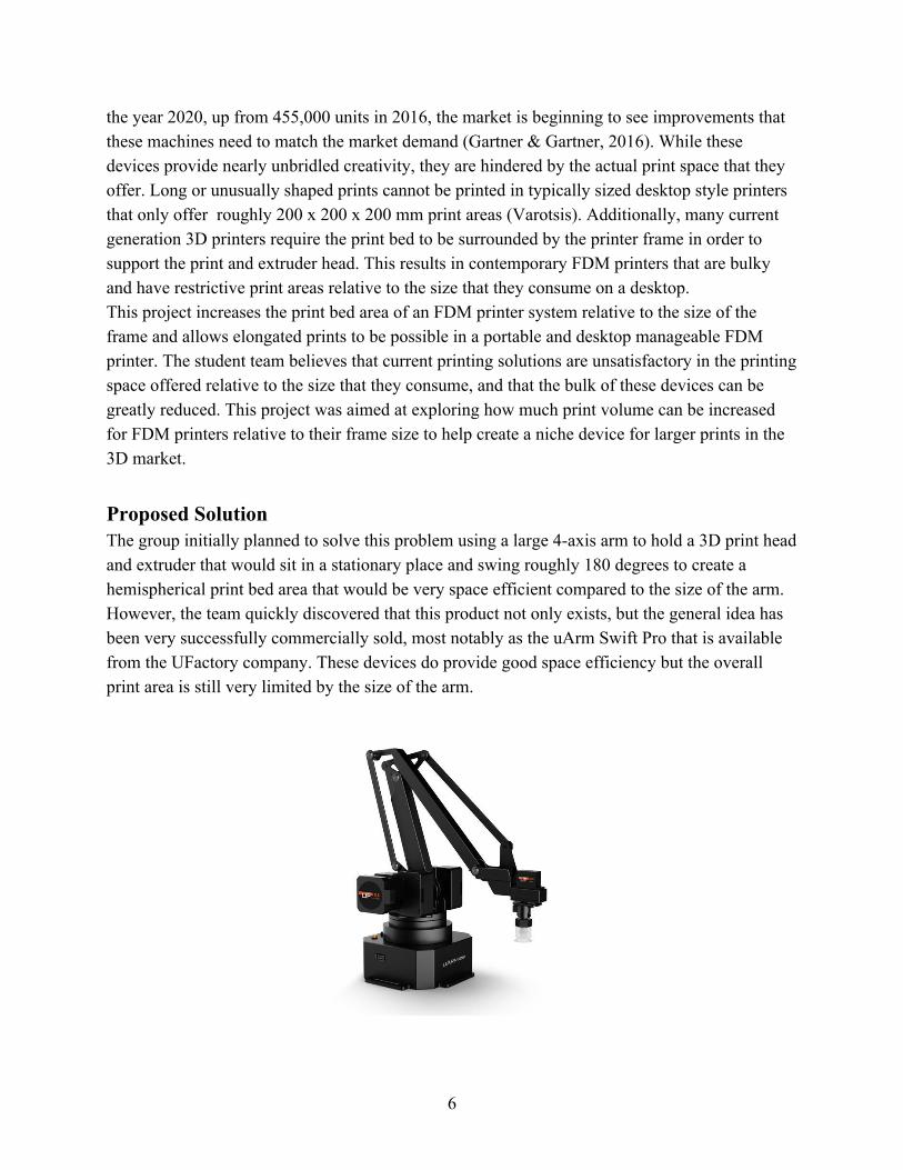
the year 2020, up from 455,000 units in 2016, the market is beginning to see improvements that these machines need to match the market demand (Gartner & Gartner, 2016). While these devices provide nearly unbridled creativity, they are hindered by the actual print space that they offer. Long or unusually shaped prints cannot be printed in typically sized desktop style printers that only offer roughly 200 x 200 x 200 mm print areas (Varotsis). Additionally, many current generation 3D printers require the print bed to be surrounded by the printer frame in order to support the print and extruder head. This results in contemporary FDM printers that are bulky and have restrictive print areas relative to the size that they consume on a desktop. This project increases the print bed area of an FDM printer system relative to the size of the frame and allows elongated prints to be possible in a portable and desktop manageable FDM printer. The student team believes that current printing solutions are unsatisfactory in the printing space offered relative to the size that they consume, and that the bulk of these devices can be greatly reduced. This project was aimed at exploring how much print volume can be increased for FDM printers relative to their frame size to help create a niche device for larger prints in the 3D market. Proposed Solution The group initially planned to solve this problem using a large 4-axis arm to hold a 3D print head and extruder that would sit in a stationary place and swing roughly 180 degrees to create a hemispherical print bed area that would be very space efficient compared to the size of the arm. However, the team quickly discovered that this product not only exists, but the general idea has been very successfully commercially sold, most notably as the uArm Swift Pro that is available from the UFactory company. These devices do provide good space efficiency but the overall print area is still very limited by the size of the arm.
6
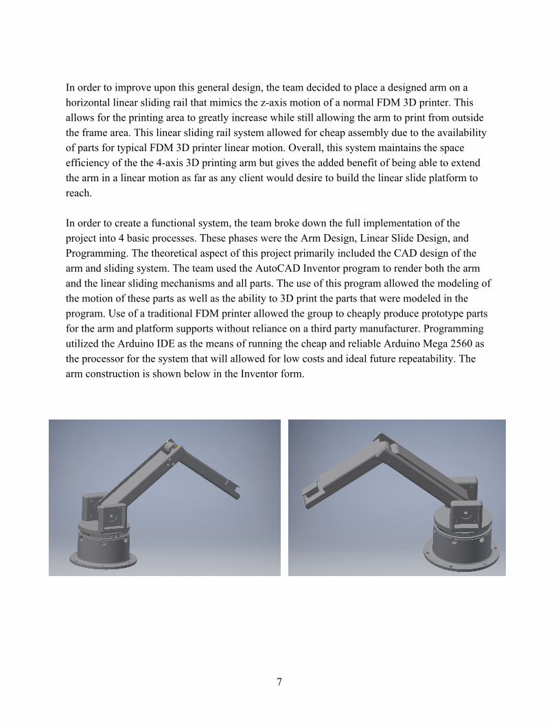
In order to improve upon this general design, the team decided to place a designed arm on a horizontal linear sliding rail that mimics the z-axis motion of a normal FDM 3D printer. This allows for the printing area to greatly increase while still allowing the arm to print from outside the frame area. This linear sliding rail system allowed for cheap assembly due to the availability of parts for typical FDM 3D printer linear motion. Overall, this system maintains the space efficiency of the the 4-axis 3D printing arm but gives the added benefit of being able to extend the arm in a linear motion as far as any client would desire to build the linear slide platform to reach. In order to create a functional system, the team broke down the full implementation of the project into 4 basic processes. These phases were the Arm Design, Linear Slide Design, and Programming. The theoretical aspect of this project primarily included the CAD design of the arm and sliding system. The team used the AutoCAD Inventor program to render both the arm and the linear sliding mechanisms and all parts. The use of this program allowed the modeling of the motion of these parts as well as the ability to 3D print the parts that were modeled in the program. Use of a traditional FDM printer allowed the group to cheaply produce prototype parts for the arm and platform supports without reliance on a third party manufacturer. Programming utilized the Arduino IDE as the means of running the cheap and reliable Arduino Mega 2560 as the processor for the system that will allowed for low costs and ideal future repeatability. The arm construction is shown below in the Inventor form.
7
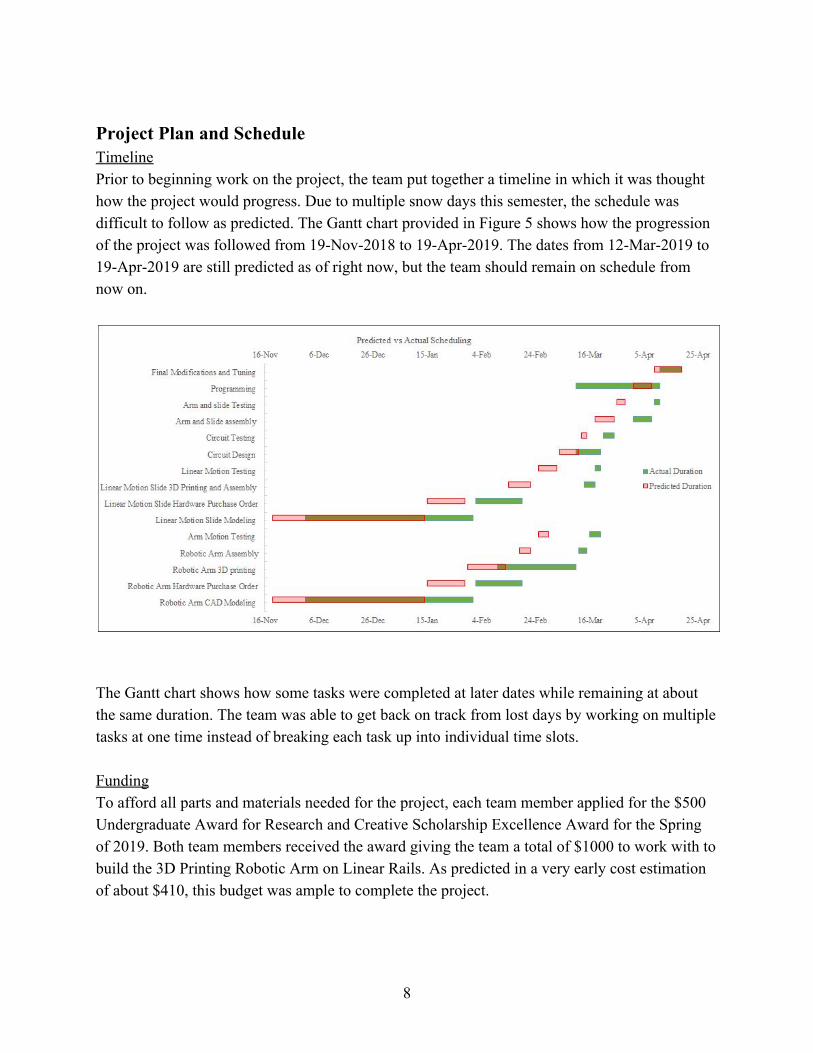
Project Plan and Schedule Timeline Prior to beginning work on the project, the team put together a timeline in which it was thought how the project would progress. Due to multiple snow days this semester, the schedule was difficult to follow as predicted. The Gantt chart provided in Figure 5 shows how the progression of the project was followed from 19-Nov-2018 to 19-Apr-2019. The dates from 12-Mar-2019 to 19-Apr-2019 are still predicted as of right now, but the team should remain on schedule from now on.
The Gantt chart shows how some tasks were completed at later dates while remaining at about the same duration. The team was able to get back on track from lost days by working on multiple tasks at one time instead of breaking each task up into individual time slots. Funding To afford all parts and materials needed for the project, each team member applied for the $500 Undergraduate Award for Research and Creative Scholarship Excellence Award for the Spring of 2019. Both team members received the award giving the team a total of $1000 to work with to build the 3D Printing Robotic Arm on Linear Rails. As predicted in a very early cost estimation of about $410, this budget was ample to complete the project.
8
Facilities In order to complete this project, the team needed the use of computers that are equipped with AutoCAD Inventor software, as well the ability to host Arduino programming software. These functionalities allowed the team to design the printable parts of the design as well as create the program to control the printing process. In order to create these parts, the team needed access to a traditional FDM 3D printer and the tools that are necessary for the assembly of the sliding mechanism and arm. In order to meet these needs, the team used the CEAS computer lab at Western Michigan University’s Parkview location for CAD design as well as personal computers for the Arduino software. Printing was completed using a printer owned by Trenton Steele’s employer and constructed and tuned over the course of the semester, and assembly was completed with tools already owned by the team. Background Research For an effective and efficient working process, the team needed to conduct some background research on various topics to gain some well-rounded knowledge of these topics which was applied to the project. 3D Printers Since the team is still essentially building a 3D printer, the printing process needed to be understood and parts required to accomplish 3D printing was needed to before purchase orders could be placed. The printing of these parts required tuning of the FDM printer and an integral knowledge of this system. In order to increase this understanding, the team built a brand new printer from parts. This printer was constructed for personal uses later so it was uninvolved in project costs or timelines but provided great experience in construction and parts sizing required for 3D printing. This printer was based on the the open sourced HyperCube 3D printer design.
9
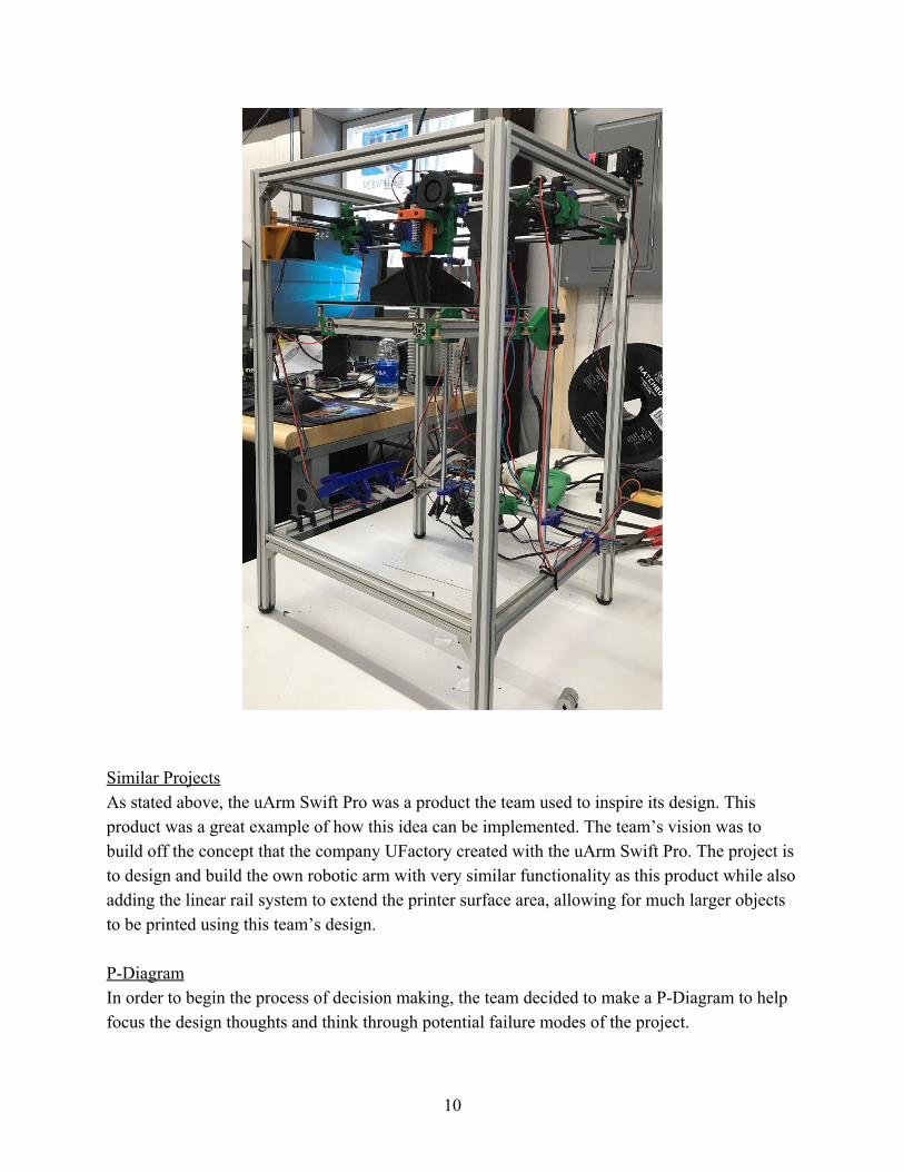
Similar Projects As stated above, the uArm Swift Pro was a product the team used to inspire its design. This product was a great example of how this idea can be implemented. The team’s vision was to build off the concept that the company UFactory created with the uArm Swift Pro. The project is to design and build the own robotic arm with very similar functionality as this product while also adding the linear rail system to extend the printer surface area, allowing for much larger objects to be printed using this team’s design. P-Diagram In order to begin the process of decision making, the team decided to make a P-Diagram to help focus the design thoughts and think through potential failure modes of the project.
10
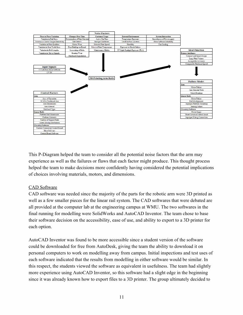
This P-Diagram helped the team to consider all the potential noise factors that the arm may experience as well as the failures or flaws that each factor might produce. This thought process helped the team to make decisions more confidently having considered the potential implications of choices involving materials, motors, and dimensions. CAD Software CAD software was needed since the majority of the parts for the robotic arm were 3D printed as well as a few smaller pieces for the linear rail system. The CAD softwares that were debated are all provided at the computer lab at the engineering campus at WMU. The two softwares in the final running for modelling were SolidWorks and AutoCAD Inventor. The team chose to base their software decision on the accessibility, ease of use, and ability to export to a 3D printer for each option. AutoCAD Inventor was found to be more accessible since a student version of the software could be downloaded for free from AutoDesk, giving the team the ability to download it on personal computers to work on modelling away from campus. Initial inspections and test uses of each software indicated that the results from modelling in either software would be similar. In this respect, the students viewed the software as equivalent in usefulness. The team had slightly more experience using AutoCAD Inventor, so this software had a slight edge in the beginning since it was already known how to export files to a 3D printer. The group ultimately decided to
11
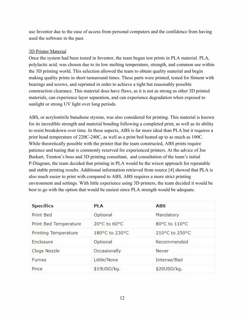
use Inventor due to the ease of access from personal computers and the confidence from having used the software in the past. 3D Printer Material Once the system had been tested in Inventor, the team began test prints in PLA material. PLA, polylactic acid, was chosen due to its low melting temperature, strength, and common use within the 3D printing world. This selection allowed the team to obtain quality material and begin making quality prints in short turnaround times. These parts were printed, tested for fitment with bearings and screws, and reprinted in order to achieve a tight but reasonably possible construction clearance. This material does have flaws, as it is not as strong as other 3D printed materials, can experience layer separation, and can experience degradation when exposed to sunlight or strong UV light over long periods. ABS, or acrylonitrile butadiene styrene, was also considered for printing. This material is known for its incredible strength and material bonding following a completed print, as well as its ability to resist breakdown over time. In these aspects, ABS is far more ideal than PLA but it requires a print head temperature of 220C-240C, as well as a print bed heated up to as much as 100C. While theoretically possible with the printer that the team constructed, ABS prints require patience and tuning that is commonly reserved for experienced printers. At the advice of Joe Burkart, Trenton’s boss and 3D printing consultant, and consultation of the team’s initial P-Diagram, the team decided that printing in PLA would be the wisest approach for repeatable and stable printing results. Additional information retrieved from source [4] showed that PLA is also much easier to print with compared to ABS. ABS requires a more strict printing environment and settings. With little experience using 3D printers, the team decided it would be best to go with the option that would be easiest since PLA strength would be adequate.
12
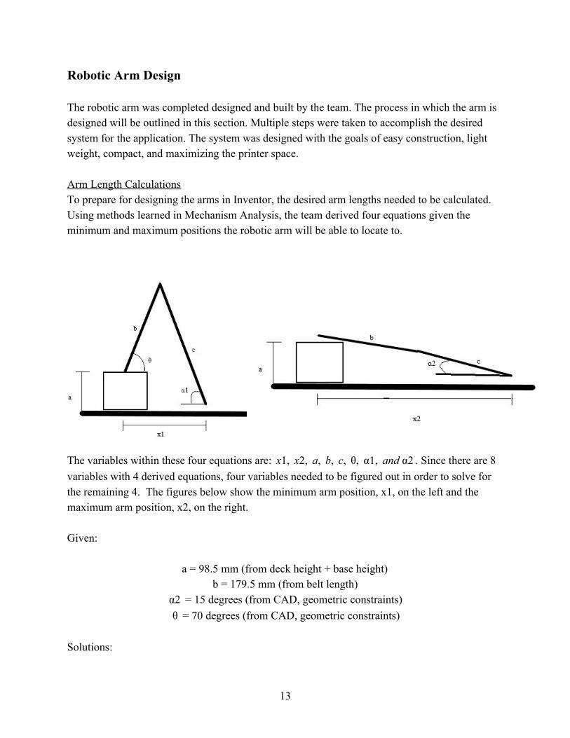
Robotic Arm Design The robotic arm was completed designed and built by the team. The process in which the arm is designed will be outlined in this section. Multiple steps were taken to accomplish the desired system for the application. The system was designed with the goals of easy construction, light weight, compact, and maximizing the printer space. Arm Length Calculations To prepare for designing the arms in Inventor, the desired arm lengths needed to be calculated. Using methods learned in Mechanism Analysis, the team derived four equations given the minimum and maximum positions the robotic arm will be able to locate to.
The variables within these four equations are: . Since there are 81, x2, a, b, c, θ, α1, and α2x variables with 4 derived equations, four variables needed to be figured out in order to solve for the remaining 4. The figures below show the minimum arm position, x1, on the left and the maximum arm position, x2, on the right. Given:
a = 98.5 mm (from deck height + base height) b = 179.5 mm (from belt length)
= 15 degrees (from CAD, geometric constraints)2α = 70 degrees (from CAD, geometric constraints)θ
Solutions:
13
x1 = 215 mm x2 = 360 mm
= 88 degrees1α c = 180 mm
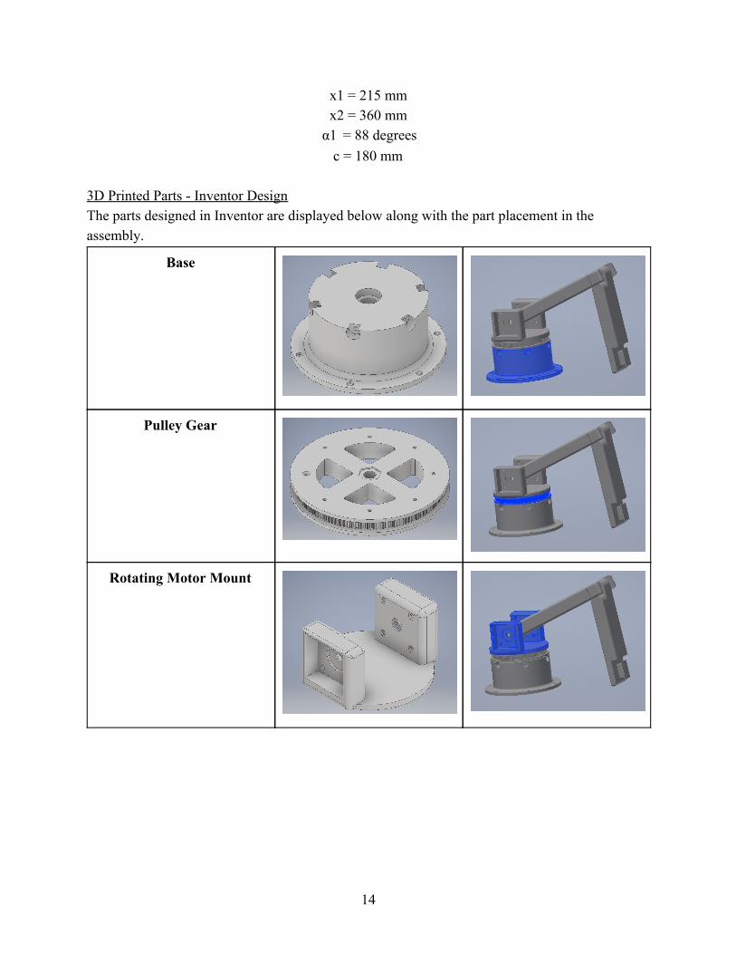
3D Printed Parts - Inventor Design The parts designed in Inventor are displayed below along with the part placement in the assembly.
Base
Pulley Gear
Rotating Motor Mount
14
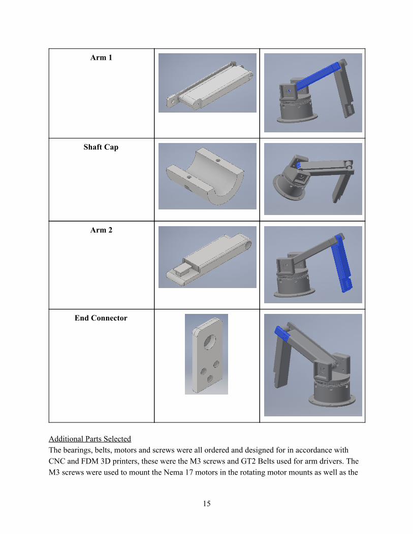
Arm 1
Shaft Cap
Arm 2
End Connector
Additional Parts Selected The bearings, belts, motors and screws were all ordered and designed for in accordance with CNC and FDM 3D printers, these were the M3 screws and GT2 Belts used for arm drivers. The M3 screws were used to mount the Nema 17 motors in the rotating motor mounts as well as the
15
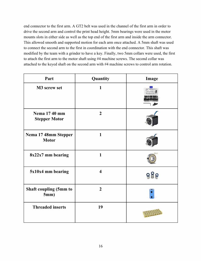
end connector to the first arm. A GT2 belt was used in the channel of the first arm in order to drive the second arm and control the print head height. 5mm bearings were used in the motor mounts slots in either side as well as the top end of the first arm and inside the arm connector. This allowed smooth and supported motion for each arm once attached. A 5mm shaft was used to connect the second arm to the first in coordination with the end connector. This shaft was modified by the team with a grinder to have a key. Finally, two 5mm collars were used, the first to attach the first arm to the motor shaft using #4 machine screws. The second collar was attached to the keyed shaft on the second arm with #4 machine screws to control arm rotation.
Part Quantity Image
M3 screw set 1
Nema 17 40 mm Stepper Motor
2
Nema 17 48mm Stepper Motor
1
8x22x7 mm bearing 1
5x10x4 mm bearing 4
Shaft coupling (5mm to 5mm)
2
Threaded inserts 19
16
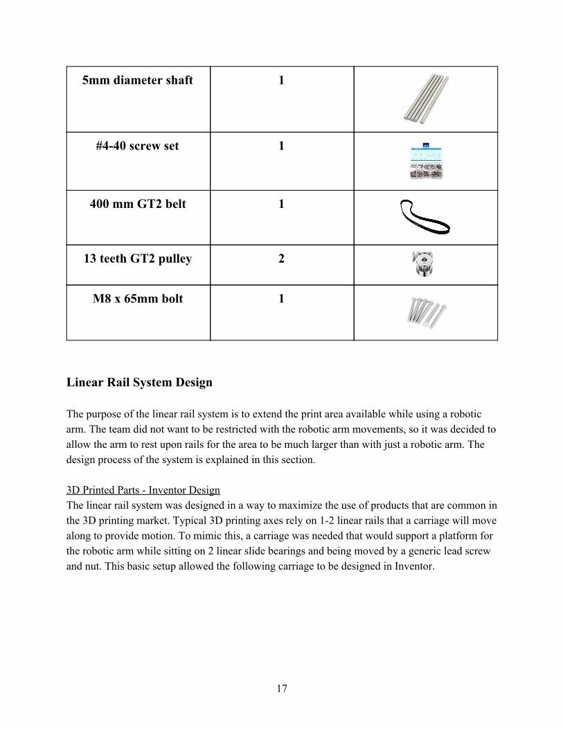
5mm diameter shaft 1
#4-40 screw set 1
400 mm GT2 belt 1
13 teeth GT2 pulley 2
M8 x 65mm bolt 1
Linear Rail System Design The purpose of the linear rail system is to extend the print area available while using a robotic arm. The team did not want to be restricted with the robotic arm movements, so it was decided to allow the arm to rest upon rails for the area to be much larger than with just a robotic arm. The design process of the system is explained in this section. 3D Printed Parts - Inventor Design The linear rail system was designed in a way to maximize the use of products that are common in the 3D printing market. Typical 3D printing axes rely on 1-2 linear rails that a carriage will move along to provide motion. To mimic this, a carriage was needed that would support a platform for the robotic arm while sitting on 2 linear slide bearings and being moved by a generic lead screw and nut. This basic setup allowed the following carriage to be designed in Inventor.
17
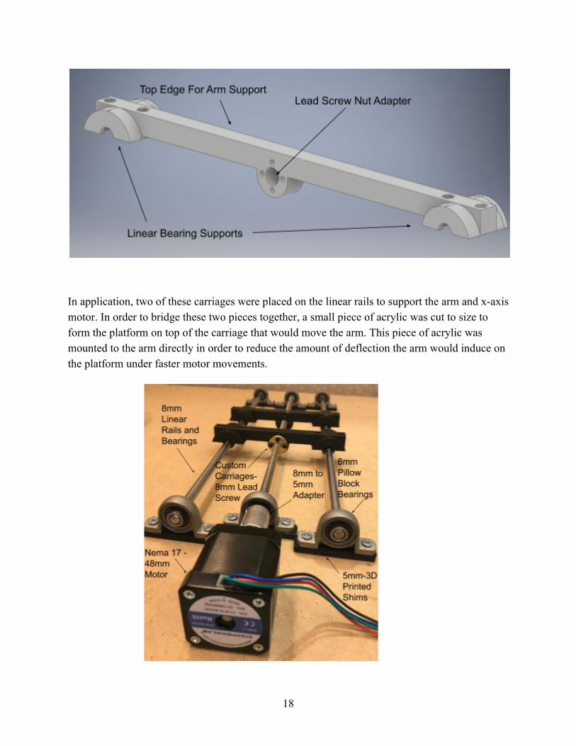
In application, two of these carriages were placed on the linear rails to support the arm and x-axis motor. In order to bridge these two pieces together, a small piece of acrylic was cut to size to form the platform on top of the carriage that would move the arm. This piece of acrylic was mounted to the arm directly in order to reduce the amount of deflection the arm would induce on the platform under faster motor movements.
18
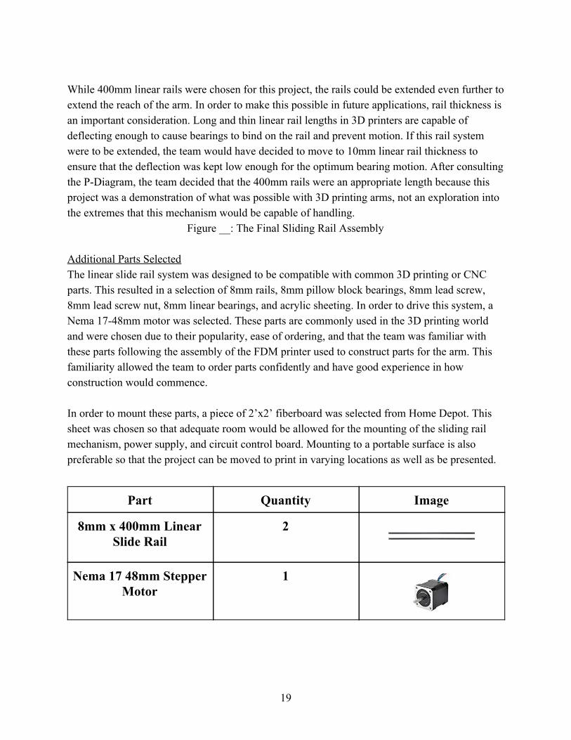
While 400mm linear rails were chosen for this project, the rails could be extended even further to extend the reach of the arm. In order to make this possible in future applications, rail thickness is an important consideration. Long and thin linear rail lengths in 3D printers are capable of deflecting enough to cause bearings to bind on the rail and prevent motion. If this rail system were to be extended, the team would have decided to move to 10mm linear rail thickness to ensure that the deflection was kept low enough for the optimum bearing motion. After consulting the P-Diagram, the team decided that the 400mm rails were an appropriate length because this project was a demonstration of what was possible with 3D printing arms, not an exploration into the extremes that this mechanism would be capable of handling.
Figure __: The Final Sliding Rail Assembly Additional Parts Selected The linear slide rail system was designed to be compatible with common 3D printing or CNC parts. This resulted in a selection of 8mm rails, 8mm pillow block bearings, 8mm lead screw, 8mm lead screw nut, 8mm linear bearings, and acrylic sheeting. In order to drive this system, a Nema 17-48mm motor was selected. These parts are commonly used in the 3D printing world and were chosen due to their popularity, ease of ordering, and that the team was familiar with these parts following the assembly of the FDM printer used to construct parts for the arm. This familiarity allowed the team to order parts confidently and have good experience in how construction would commence. In order to mount these parts, a piece of 2’x2’ fiberboard was selected from Home Depot. This sheet was chosen so that adequate room would be allowed for the mounting of the sliding rail mechanism, power supply, and circuit control board. Mounting to a portable surface is also preferable so that the project can be moved to print in varying locations as well as be presented.
Part Quantity Image
8mm x 400mm Linear Slide Rail
2
Nema 17 48mm Stepper Motor
1
19
8mm x 295mm Lead Screw
1
8mm Lead Screw Nut 2
8mm Pillow Block Bearing
6
#8-¾” Wood Screw 12
5mm 3D Printed Shims 1
3D Printed Carriage 2
24” x 24” Fiberboard 1
24” x 24” Acrylic Board 1
20
Printing Capability
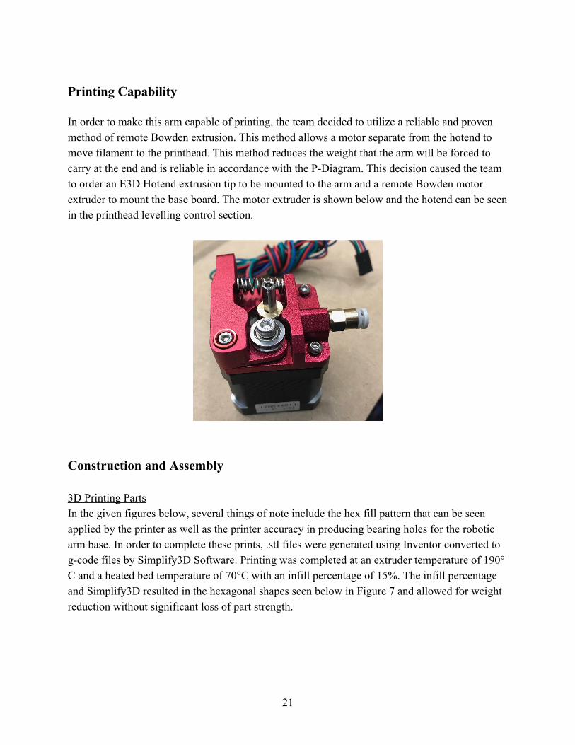
In order to make this arm capable of printing, the team decided to utilize a reliable and proven method of remote Bowden extrusion. This method allows a motor separate from the hotend to move filament to the printhead. This method reduces the weight that the arm will be forced to carry at the end and is reliable in accordance with the P-Diagram. This decision caused the team to order an E3D Hotend extrusion tip to be mounted to the arm and a remote Bowden motor extruder to mount the base board. The motor extruder is shown below and the hotend can be seen in the printhead levelling control section.
Construction and Assembly 3D Printing Parts In the given figures below, several things of note include the hex fill pattern that can be seen applied by the printer as well as the printer accuracy in producing bearing holes for the robotic arm base. In order to complete these prints, .stl files were generated using Inventor converted to g-code files by Simplify3D Software. Printing was completed at an extruder temperature of 190° C and a heated bed temperature of 70°C with an infill percentage of 15%. The infill percentage and Simplify3D resulted in the hexagonal shapes seen below in Figure 7 and allowed for weight reduction without significant loss of part strength.
21
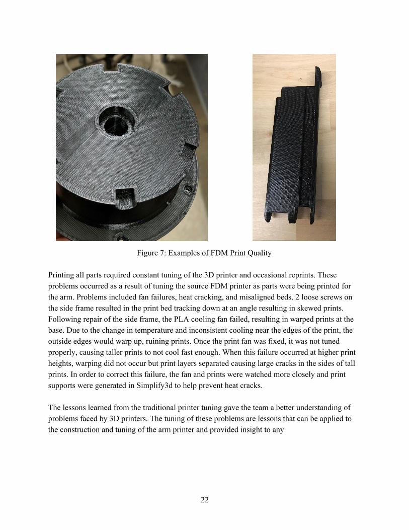
Figure 7: Examples of FDM Print Quality Printing all parts required constant tuning of the 3D printer and occasional reprints. These problems occurred as a result of tuning the source FDM printer as parts were being printed for the arm. Problems included fan failures, heat cracking, and misaligned beds. 2 loose screws on the side frame resulted in the print bed tracking down at an angle resulting in skewed prints. Following repair of the side frame, the PLA cooling fan failed, resulting in warped prints at the base. Due to the change in temperature and inconsistent cooling near the edges of the print, the outside edges would warp up, ruining prints. Once the print fan was fixed, it was not tuned properly, causing taller prints to not cool fast enough. When this failure occurred at higher print heights, warping did not occur but print layers separated causing large cracks in the sides of tall prints. In order to correct this failure, the fan and prints were watched more closely and print supports were generated in Simplify3d to help prevent heat cracks. The lessons learned from the traditional printer tuning gave the team a better understanding of problems faced by 3D printers. The tuning of these problems are lessons that can be applied to the construction and tuning of the arm printer and provided insight to any
22
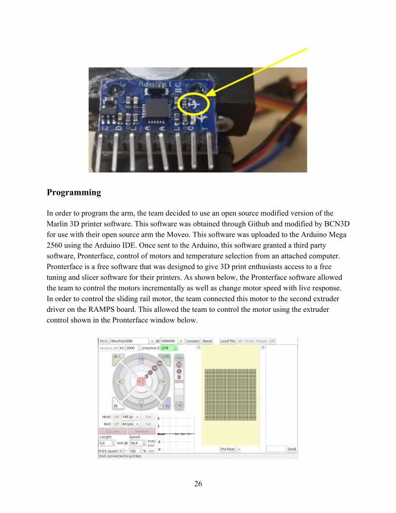
Circuitry
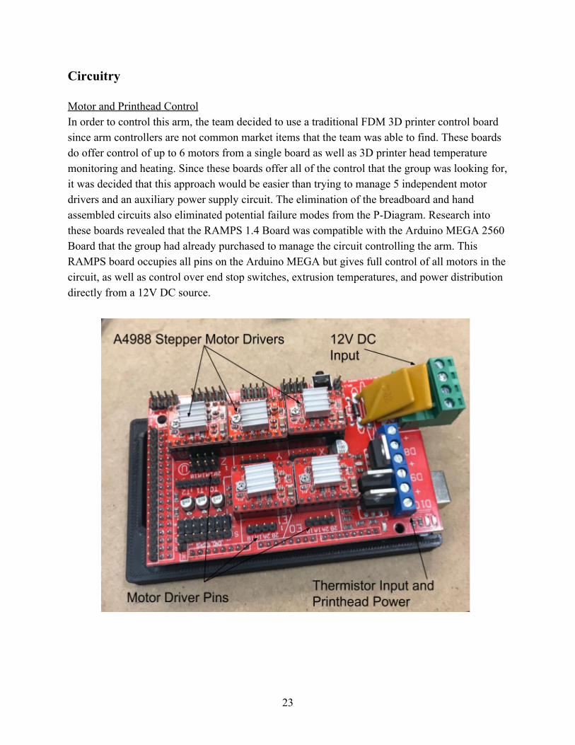
Motor and Printhead Control In order to control this arm, the team decided to use a traditional FDM 3D printer control board since arm controllers are not common market items that the team was able to find. These boards do offer control of up to 6 motors from a single board as well as 3D printer head temperature monitoring and heating. Since these boards offer all of the control that the group was looking for, it was decided that this approach would be easier than trying to manage 5 independent motor drivers and an auxiliary power supply circuit. The elimination of the breadboard and hand assembled circuits also eliminated potential failure modes from the P-Diagram. Research into these boards revealed that the RAMPS 1.4 Board was compatible with the Arduino MEGA 2560 Board that the group had already purchased to manage the circuit controlling the arm. This RAMPS board occupies all pins on the Arduino MEGA but gives full control of all motors in the circuit, as well as control over end stop switches, extrusion temperatures, and power distribution directly from a 12V DC source.
23
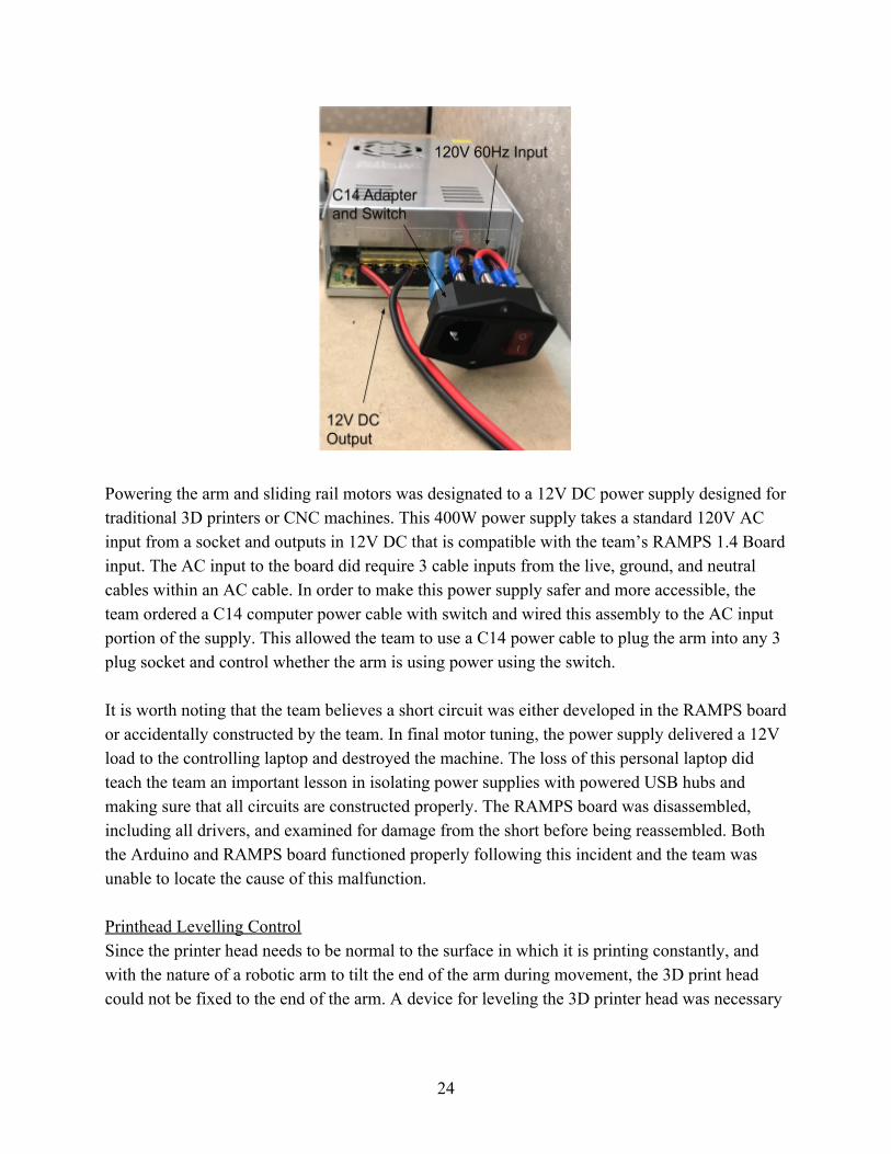
Powering the arm and sliding rail motors was designated to a 12V DC power supply designed for traditional 3D printers or CNC machines. This 400W power supply takes a standard 120V AC input from a socket and outputs in 12V DC that is compatible with the team’s RAMPS 1.4 Board input. The AC input to the board did require 3 cable inputs from the live, ground, and neutral cables within an AC cable. In order to make this power supply safer and more accessible, the team ordered a C14 computer power cable with switch and wired this assembly to the AC input portion of the supply. This allowed the team to use a C14 power cable to plug the arm into any 3 plug socket and control whether the arm is using power using the switch. It is worth noting that the team believes a short circuit was either developed in the RAMPS board or accidentally constructed by the team. In final motor tuning, the power supply delivered a 12V load to the controlling laptop and destroyed the machine. The loss of this personal laptop did teach the team an important lesson in isolating power supplies with powered USB hubs and making sure that all circuits are constructed properly. The RAMPS board was disassembled, including all drivers, and examined for damage from the short before being reassembled. Both the Arduino and RAMPS board functioned properly following this incident and the team was unable to locate the cause of this malfunction. Printhead Levelling Control Since the printer head needs to be normal to the surface in which it is printing constantly, and with the nature of a robotic arm to tilt the end of the arm during movement, the 3D print head could not be fixed to the end of the arm. A device for leveling the 3D printer head was necessary
24
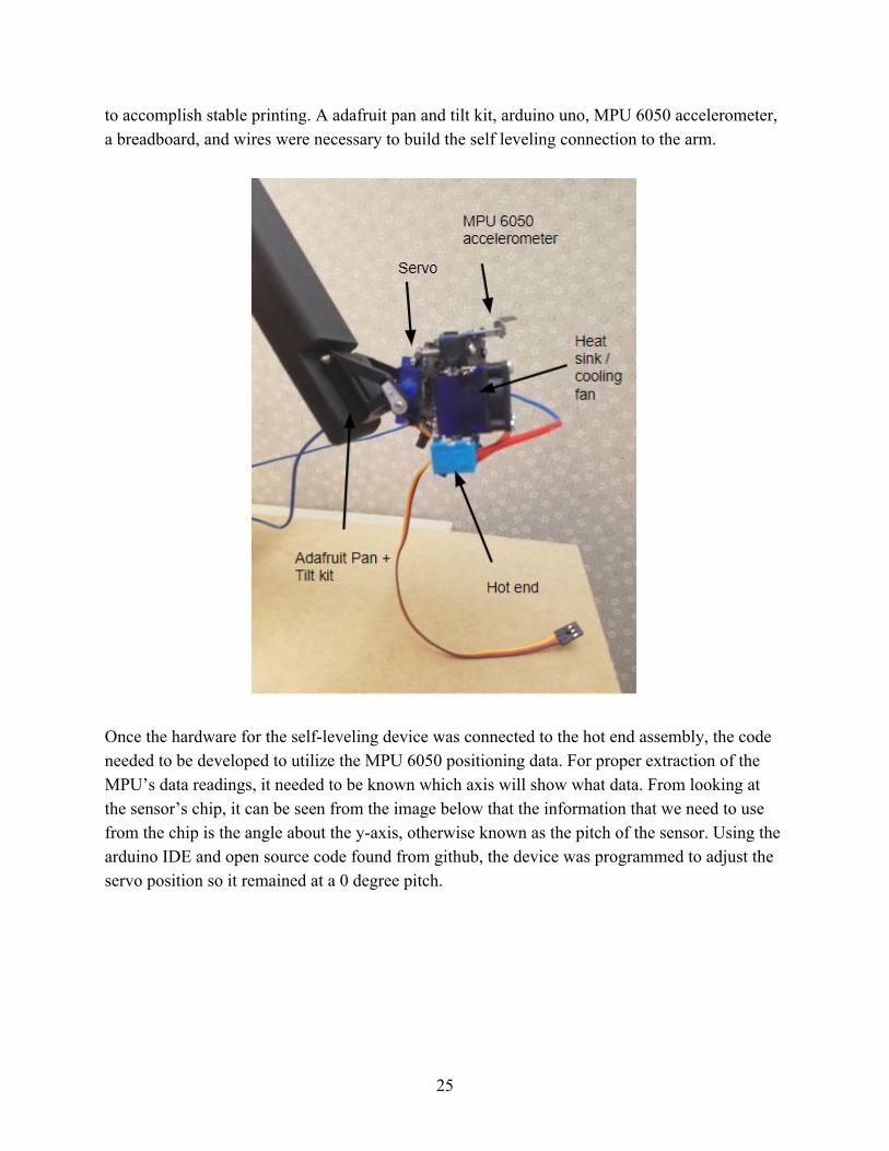
to accomplish stable printing. A adafruit pan and tilt kit, arduino uno, MPU 6050 accelerometer, a breadboard, and wires were necessary to build the self leveling connection to the arm.
Once the hardware for the self-leveling device was connected to the hot end assembly, the code needed to be developed to utilize the MPU 6050 positioning data. For proper extraction of the MPU’s data readings, it needed to be known which axis will show what data. From looking at the sensor’s chip, it can be seen from the image below that the information that we need to use from the chip is the angle about the y-axis, otherwise known as the pitch of the sensor. Using the arduino IDE and open source code found from github, the device was programmed to adjust the servo position so it remained at a 0 degree pitch.
25
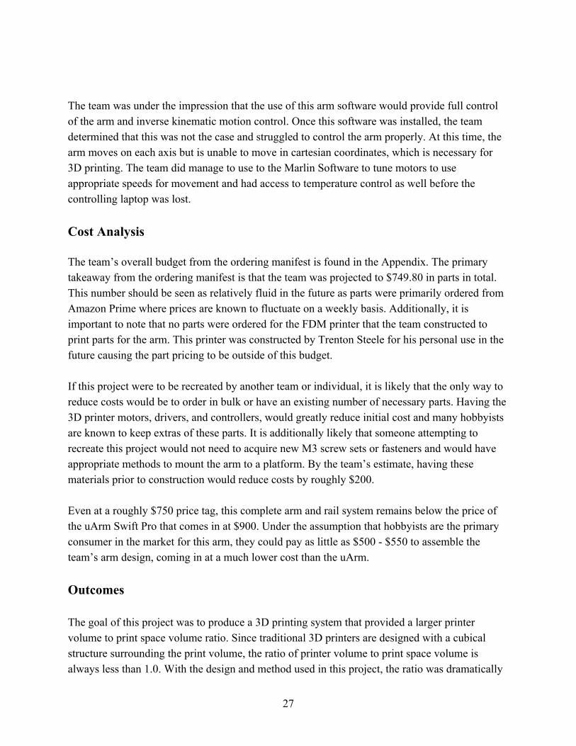
Programming
In order to program the arm, the team decided to use an open source modified version of the Marlin 3D printer software. This software was obtained through Github and modified by BCN3D for use with their open source arm the Moveo. This software was uploaded to the Arduino Mega 2560 using the Arduino IDE. Once sent to the Arduino, this software granted a third party software, Pronterface, control of motors and temperature selection from an attached computer. Pronterface is a free software that was designed to give 3D print enthusiasts access to a free tuning and slicer software for their printers. As shown below, the Pronterface software allowed the team to control the motors incrementally as well as change motor speed with live response. In order to control the sliding rail motor, the team connected this motor to the second extruder driver on the RAMPS board. This allowed the team to control the motor using the extruder control shown in the Pronterface window below.
26
The team was under the impression that the use of this arm software would provide full control of the arm and inverse kinematic motion control. Once this software was installed, the team determined that this was not the case and struggled to control the arm properly. At this time, the arm moves on each axis but is unable to move in cartesian coordinates, which is necessary for 3D printing. The team did manage to use to the Marlin Software to tune motors to use appropriate speeds for movement and had access to temperature control as well before the controlling laptop was lost. Cost Analysis
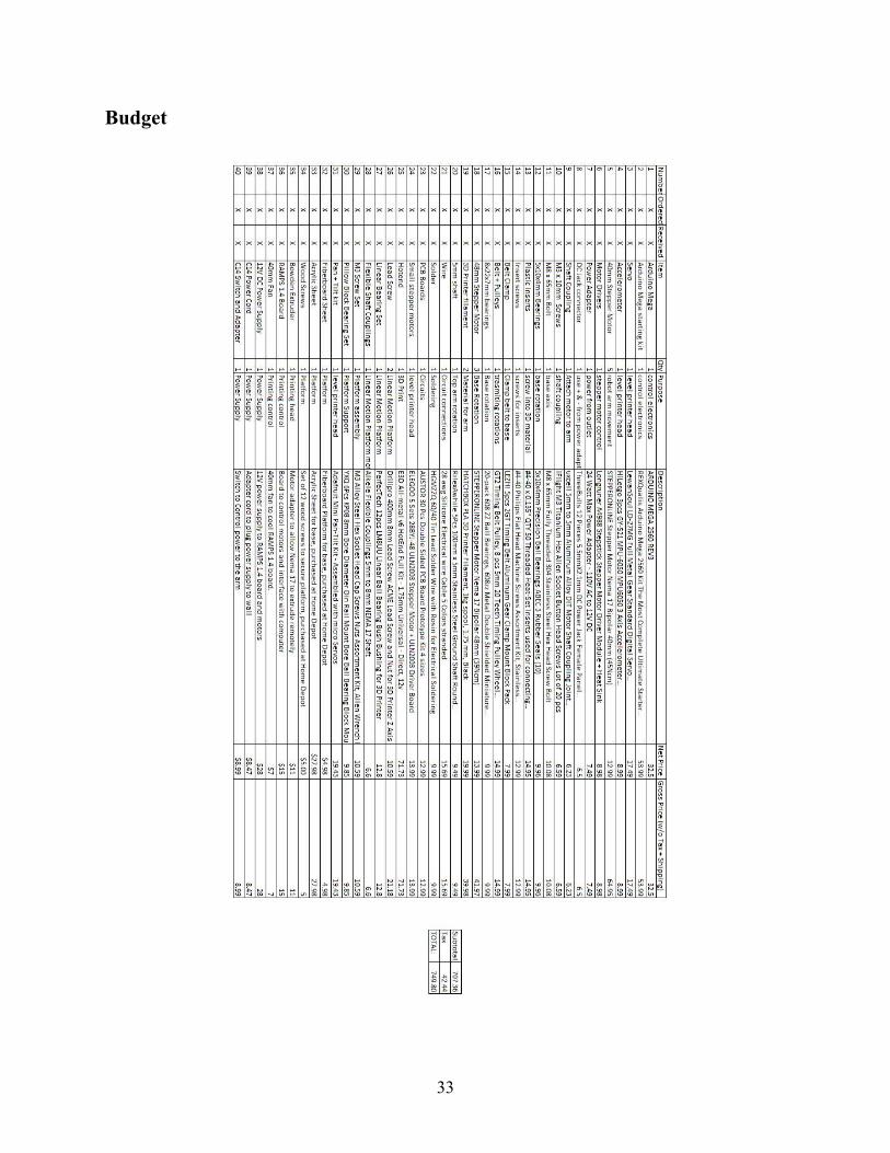
The team’s overall budget from the ordering manifest is found in the Appendix. The primary takeaway from the ordering manifest is that the team was projected to $749.80 in parts in total. This number should be seen as relatively fluid in the future as parts were primarily ordered from Amazon Prime where prices are known to fluctuate on a weekly basis. Additionally, it is important to note that no parts were ordered for the FDM printer that the team constructed to print parts for the arm. This printer was constructed by Trenton Steele for his personal use in the future causing the part pricing to be outside of this budget. If this project were to be recreated by another team or individual, it is likely that the only way to reduce costs would be to order in bulk or have an existing number of necessary parts. Having the 3D printer motors, drivers, and controllers, would greatly reduce initial cost and many hobbyists are known to keep extras of these parts. It is additionally likely that someone attempting to recreate this project would not need to acquire new M3 screw sets or fasteners and would have appropriate methods to mount the arm to a platform. By the team’s estimate, having these materials prior to construction would reduce costs by roughly $200. Even at a roughly $750 price tag, this complete arm and rail system remains below the price of the uArm Swift Pro that comes in at $900. Under the assumption that hobbyists are the primary consumer in the market for this arm, they could pay as little as $500 - $550 to assemble the team’s arm design, coming in at a much lower cost than the uArm. Outcomes The goal of this project was to produce a 3D printing system that provided a larger printer volume to print space volume ratio. Since traditional 3D printers are designed with a cubical structure surrounding the print volume, the ratio of printer volume to print space volume is always less than 1.0. With the design and method used in this project, the ratio was dramatically
27
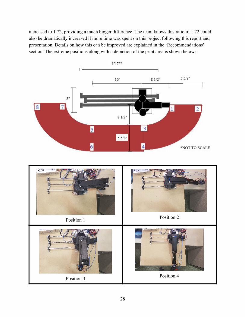
increased to 1.72, providing a much bigger difference. The team knows this ratio of 1.72 could also be dramatically increased if more time was spent on this project following this report and presentation. Details on how this can be improved are explained in the ‘Recommendations’ section. The extreme positions along with a depiction of the print area is shown below:
Position 1
Position 2
Position 3
Position 4
28
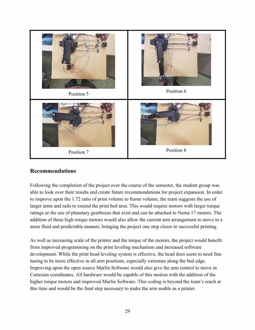
Position 5
Position 6
Position 7
Position 8
Recommendations Following the completion of the project over the course of the semester, the student group was able to look over their results and create future recommendations for project expansion. In order to improve upon the 1.72 ratio of print volume to frame volume, the team suggests the use of larger arms and rails to extend the print bed area. This would require motors with larger torque ratings or the use of planetary gearboxes that exist and can be attached to Nema 17 motors. The addition of these high torque motors would also allow the current arm arrangement to move in a more fluid and predictable manner, bringing the project one step closer to successful printing. As well as increasing scale of the printer and the torque of the motors, the project would benefit from improved programming on the print leveling mechanism and increased software development. While the print head leveling system is effective, the head does seem to need fine tuning to be more effective in all arm positions, especially extremes along the bed edge. Improving upon the open source Marlin Software would also give the arm control to move in Cartesian coordinates. All hardware would be capable of this motion with the addition of the higher torque motors and improved Marlin Software. This coding is beyond the team’s reach at this time and would be the final step necessary to make the arm usable as a printer.
29

Final recommendations to improve the project would be circuitry and aesthetic improvements. Moving the print head leveling circuit to a pcb chip would help to reduce clutter and help streamline the wire management of the arm circuitry. Integrating the power supply to a covered box would be both safer and more aesthetic, giving room for wires to be looped and hidden from the back of the board. Finally, when controlling the arm, the team recommends the use an externally powered USB hub to connect between the computer using the Pronterface software and the arm. Following the short circuit and bricking of the controlling laptop, the team believes that this external USB allows for a level of separation and protection between the printer and computer.
30
References [1] Gartner, A. A., & Gartner, R. M. (2016, October 13). Gartner Says Worldwide Shipments of 3D Printers to Grow 108 Percent in 2016. Retrieved November 20, 2018, from https://www.gartner.com/newsroom/id/3476317
[2] Varotsis, A. B. (n.d.). Introduction to FDM 3D printing. Retrieved November 20, 2018, from https://www.3dhubs.com/knowledge-base/introduction-fdm-3d-printing
[3] Landin. (2015, November 10). Big 3D Printer. Retrieved March 4, 2019, from http://www.soliforum.com/topic/12793/big-printer/ [4] PLA vs ABS Filament: Plastic Strength, Flexibility Compared! Which Is Better For 3D Printing? (n.d.). Retrieved March 14, 19, from https://www.allthat3d.com/pla-vs-abs/
31

Appendix Software used: Autodesk Inventor - 3D CAD modelling and design Arduino IDE - Programming Marlin - Motor programming Pronterface - Motor control
32
Budget
33
Instructions
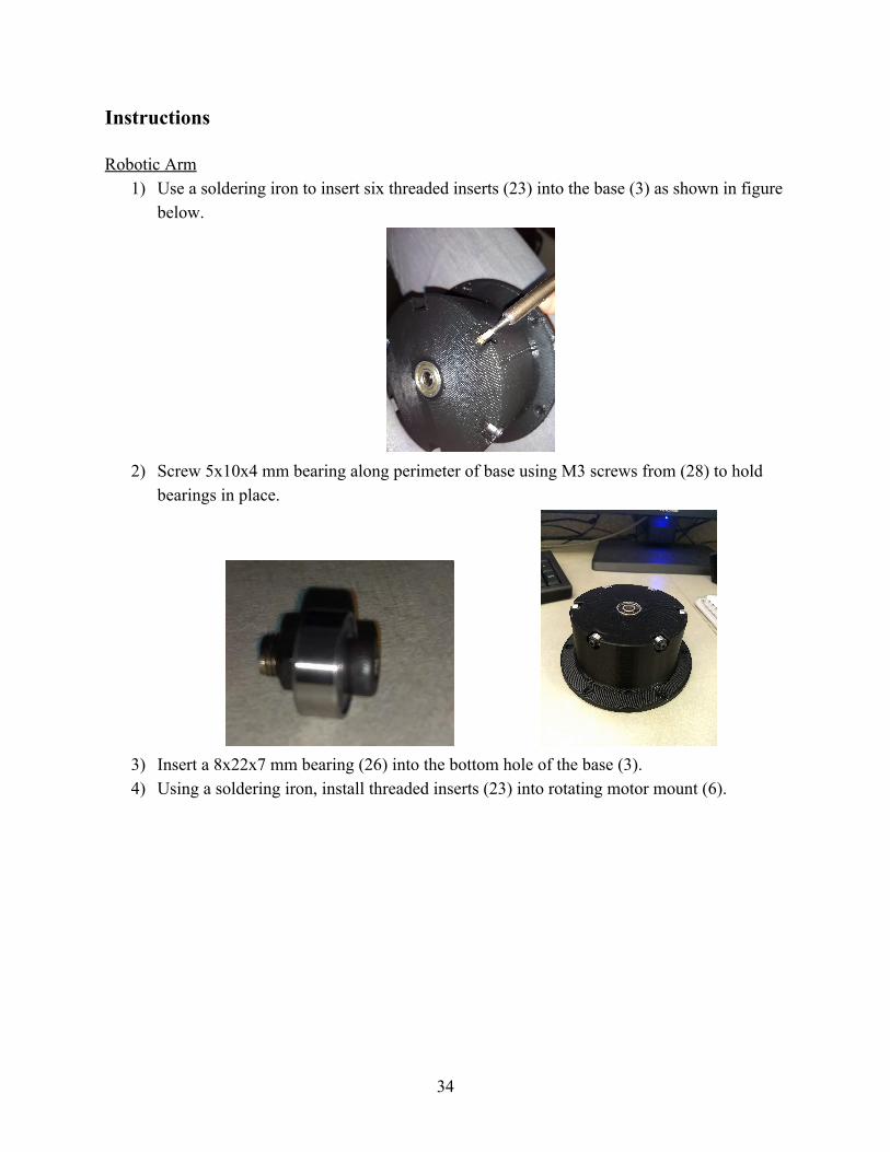
Robotic Arm 1) Use a soldering iron to insert six threaded inserts (23) into the base (3) as shown in figure
below.
2) Screw 5x10x4 mm bearing along perimeter of base using M3 screws from (28) to hold
bearings in place.
3) Insert a 8x22x7 mm bearing (26) into the bottom hole of the base (3). 4) Using a soldering iron, install threaded inserts (23) into rotating motor mount (6).
34
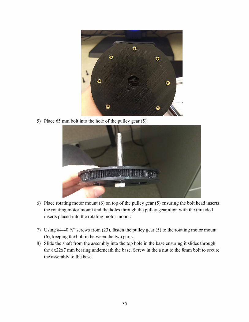
5) Place 65 mm bolt into the hole of the pulley gear (5).
6) Place rotating motor mount (6) on top of the pulley gear (5) ensuring the bolt head inserts
the rotating motor mount and the holes through the pulley gear align with the threaded inserts placed into the rotating motor mount.
7) Using #4-40 ½” screws from (23), fasten the pulley gear (5) to the rotating motor mount
(6), keeping the bolt in between the two parts. 8) Slide the shaft from the assembly into the top hole in the base ensuring it slides through
the 8x22x7 mm bearing underneath the base. Screw in the a nut to the 8mm bolt to secure the assembly to the base.
35
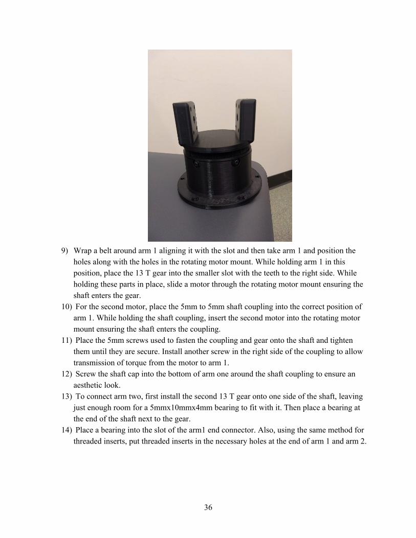
9) Wrap a belt around arm 1 aligning it with the slot and then take arm 1 and position the
holes along with the holes in the rotating motor mount. While holding arm 1 in this position, place the 13 T gear into the smaller slot with the teeth to the right side. While holding these parts in place, slide a motor through the rotating motor mount ensuring the shaft enters the gear.
10) For the second motor, place the 5mm to 5mm shaft coupling into the correct position of arm 1. While holding the shaft coupling, insert the second motor into the rotating motor mount ensuring the shaft enters the coupling.
11) Place the 5mm screws used to fasten the coupling and gear onto the shaft and tighten them until they are secure. Install another screw in the right side of the coupling to allow transmission of torque from the motor to arm 1.
12) Screw the shaft cap into the bottom of arm one around the shaft coupling to ensure an aesthetic look.
13) To connect arm two, first install the second 13 T gear onto one side of the shaft, leaving just enough room for a 5mmx10mmx4mm bearing to fit with it. Then place a bearing at the end of the shaft next to the gear.
14) Place a bearing into the slot of the arm1 end connector. Also, using the same method for threaded inserts, put threaded inserts in the necessary holes at the end of arm 1 and arm 2.
36
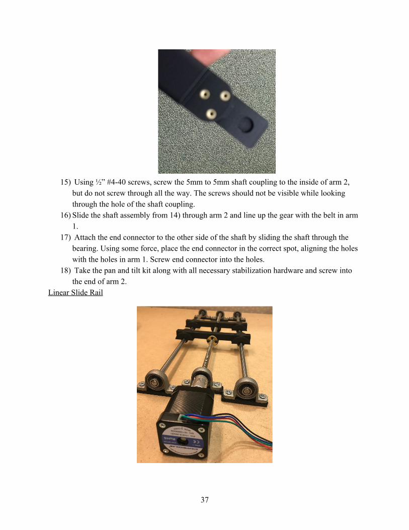
15) Using ½” #4-40 screws, screw the 5mm to 5mm shaft coupling to the inside of arm 2,
but do not screw through all the way. The screws should not be visible while looking through the hole of the shaft coupling.
16) Slide the shaft assembly from 14) through arm 2 and line up the gear with the belt in arm 1.
17) Attach the end connector to the other side of the shaft by sliding the shaft through the bearing. Using some force, place the end connector in the correct spot, aligning the holes with the holes in arm 1. Screw end connector into the holes.
18) Take the pan and tilt kit along with all necessary stabilization hardware and screw into the end of arm 2.
Linear Slide Rail
37
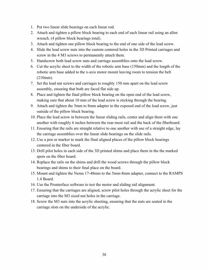
1. Put two linear slide bearings on each linear rod. 2. Attach and tighten a pillow block bearing to each end of each linear rail using an allen
wrench. (4 pillow block bearings total). 3. Attach and tighten one pillow block bearing to the end of one side of the lead screw. 4. Slide the lead screw nuts into the custom centered holes in the 3D Printed carriages and
screw in the 4 M3 screws to permanently attach them. 5. Handscrew both lead screw nuts and carriage assemblies onto the lead screw. 6. Cut the acrylic sheet to the width of the robotic arm base (150mm) and the length of the
robotic arm base added to the x-axis motor mount leaving room to tension the belt (210mm).
7. Set the lead nut screws and carriages to roughly 150 mm apart on the lead screw assembly, ensuring that both are faced flat side up.
8. Place and tighten the final pillow block bearing on the open end of the lead screw, making sure that about 10 mm of the lead screw is sticking through the bearing.
9. Attach and tighten the 5mm to 8mm adapter to the exposed end of the lead screw, just outside of the pillow block bearing.
10. Place the lead screw in between the linear sliding rails, center and align them with one another with roughly 6 inches between the rear-most rail and the back of the fiberboard.
11. Ensuring that the rails are straight relative to one another with use of a straight edge, lay the carriage assemblies over the linear slide bearings on the slide rails.
12. Use a pen or marker to mark the final aligned places of the pillow block bearings centered in the fiber board.
13. Drill pilot holes in each side of the 3D printed shims and place them in the the marked spots on the fiber board.
14. Replace the rails on the shims and drill the wood screws through the pillow block bearings and shims to their final place on the board.
15. Mount and tighten the Nema 17-48mm to the 5mm-8mm adapter, connect to the RAMPS 1.4 Board.
16. Use the Pronterface software to test the motor and sliding rail alignment. 17. Ensuring that the carriages are aligned, screw pilot holes through the acrylic sheet for the
carriage into the M3 sized nut holes in the carriage. 18. Screw the M3 nuts into the acrylic sheeting, ensuring that the nuts are seated in the
carriage slots on the underside of the acrylic.
38
Circuitry and Programming
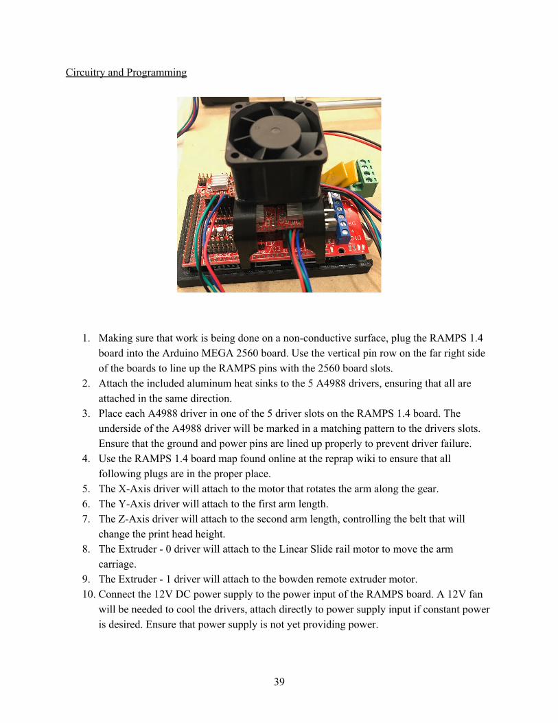
1. Making sure that work is being done on a non-conductive surface, plug the RAMPS 1.4 board into the Arduino MEGA 2560 board. Use the vertical pin row on the far right side of the boards to line up the RAMPS pins with the 2560 board slots.
2. Attach the included aluminum heat sinks to the 5 A4988 drivers, ensuring that all are attached in the same direction.
3. Place each A4988 driver in one of the 5 driver slots on the RAMPS 1.4 board. The underside of the A4988 driver will be marked in a matching pattern to the drivers slots. Ensure that the ground and power pins are lined up properly to prevent driver failure.
4. Use the RAMPS 1.4 board map found online at the reprap wiki to ensure that all following plugs are in the proper place.
5. The X-Axis driver will attach to the motor that rotates the arm along the gear. 6. The Y-Axis driver will attach to the first arm length. 7. The Z-Axis driver will attach to the second arm length, controlling the belt that will
change the print head height. 8. The Extruder - 0 driver will attach to the Linear Slide rail motor to move the arm
carriage. 9. The Extruder - 1 driver will attach to the bowden remote extruder motor. 10. Connect the 12V DC power supply to the power input of the RAMPS board. A 12V fan
will be needed to cool the drivers, attach directly to power supply input if constant power is desired. Ensure that power supply is not yet providing power.
39
11. Use the USB-B connector on the Arduino to connect to an externally powered USB hub and a controlling computer equipped with Arduino IDE.
12. Acquire both Marlin Moveo from BCN3D and PronterFace Software from Github. 13. Use the Arduino IDE to upload Marlin Moveo to the board. Ensure that the board is
ported properly and identified by the computer. 14. Begin the PronterFace software, choose a baud rate of 250,000 and select the port that the
Arduino has been connected to. 15. Once the PronterFace interface has confirmed connection to the board, switch on the 12V
power supply. 16. Test motor movement with the PronterFace interface. Motor speed can be found and
adjusted in the Marlin Configuration.h file. In order to update this speed, PronterFace must be disconnected, Marlin re-uploaded, and PronterFace reconnected to the Arduino.
40
Related Documents