The author(s) shown below used Federal funds provided by the U.S. Department of Justice and prepared the following final report: Document Title: 3D-ID: Geometric Morphometric Classification of Crania for Forensic Scientists Author: Dennis E. Slice and Ann Ross Document No.: 231196 Date Received: July 2010 Award Number: 2005-MU-BX-K078 This report has not been published by the U.S. Department of Justice. To provide better customer service, NCJRS has made this Federally- funded grant final report available electronically in addition to traditional paper copies. Opinions or points of view expressed are those of the author(s) and do not necessarily reflect the official position or policies of the U.S. Department of Justice.

Welcome message from author
This document is posted to help you gain knowledge. Please leave a comment to let me know what you think about it! Share it to your friends and learn new things together.
Transcript

The author(s) shown below used Federal funds provided by the U.S. Department of Justice and prepared the following final report: Document Title: 3D-ID: Geometric Morphometric Classification of
Crania for Forensic Scientists Author: Dennis E. Slice and Ann Ross Document No.: 231196
Date Received: July 2010 Award Number: 2005-MU-BX-K078 This report has not been published by the U.S. Department of Justice. To provide better customer service, NCJRS has made this Federally-funded grant final report available electronically in addition to traditional paper copies.
Opinions or points of view expressed are those
of the author(s) and do not necessarily reflect the official position or policies of the U.S.
Department of Justice.

3D-ID
Geometric Morphometric Classification of Crania for Forensic Scientists
Dennis E. Slice and Ann Ross
Sponsored in part by National Institute of Justice Grant
2005-MU-BX-K078to
Ann Ross
This document is a research report submitted to the U.S. Department of Justice. This report has not been published by the Department. Opinions or points of view expressed are those of the author(s) and do not necessarily reflect the official position or policies of the U.S. Department of Justice.

COPYRIGHT © 2009- by Dennis E. Slice
VERSION: 1.0 (13JUL2009)
CREDITS:FORENSIC ANTHROPOLOGY
Ann RossNorth Carolina State UniversityRaleigh, North Carolina, USA
PROGRAMMING AND STATISTICSDennis E. SliceFlorida State UniversityTallahassee, Florida, USA
SPLASH IMAGERob O'NeillPratt Institutehttp://www.morphometric.com/
ACKNOWLEDGEMENTS: The authors wish to thank the following for their assistance and cooperation in various ways: Hugo Cardoso (Bocage Museum, Portugal), Greg Berg, María Dolores Garralda (Universidad Complutense, Spain), Richard Jantz, Erin Kimmerle, Antonio Martinez, Janet Monge, Jose Vicente Pachar (Director General, Instituto de Medicina Legal y Ciencias Forenses, Panama), Juan Carlos Prados (Departamento de Anatomía e Embrología Humana, Spain), José Luis Prieto (Instituto Anatómico Forense, Spain), Rick Snow, Kate Spradley, Doug Ubelaker, Danny Wescott, Shanna Williams, American Museum of Natural History, C.A. Pound Human Identification Lab, Georgia Bureau of Investigation, North Carolina Office of the Chief Medical Examiner.
END-USER LICENSE AGREEMENT: The downloading and use of this software constitutes acceptance of the following: the software is to be used 'as is' and without modification, you will not distribute the software to other parties (you should direct them to the website, instead), you will not attempt to reverse engineer or extract any part of the software or accompanying data files, and no results beyond reporting the characterization of a single unknown can be published without the express, written consent of the developers.
DISCLAIMER: This software is provided only as an aid to the characterization of skeletal material. The authors accept no responsibility for its ultimate use or misuse. While significant effort has been made to ensure the program is operationally solid and computationally accurate, we provide no warranty and make no specific claims as to its accuracy or its appropriateness for use in a particular situation.
This document is a research report submitted to the U.S. Department of Justice. This report has not been published by the Department. Opinions or points of view expressed are those of the author(s) and do not necessarily reflect the official position or policies of the U.S. Department of Justice.

Table of ContentsINTRODUCTION.....................................................................................................................................5PROGRAM USAGE..................................................................................................................................6
Main Program Panels............................................................................................................................7The Main Menu...................................................................................................................................10
INSTALLATION AND SYSTEM REQUIREMENTS...........................................................................12System Requirements..........................................................................................................................12Basic Installation.................................................................................................................................12Trouble Shooting.................................................................................................................................12
LANDMARKS........................................................................................................................................13TECHNICAL DETAILS..........................................................................................................................13REFERENCES.........................................................................................................................................16
This document is a research report submitted to the U.S. Department of Justice. This report has not been published by the Department. Opinions or points of view expressed are those of the author(s) and do not necessarily reflect the official position or policies of the U.S. Department of Justice.

*** BLANK PAGE ***
This document is a research report submitted to the U.S. Department of Justice. This report has not been published by the Department. Opinions or points of view expressed are those of the author(s) and do not necessarily reflect the official position or policies of the U.S. Department of Justice.

INTRODUCTIONThe estimation of sex and ancestry are key components when rendering a biological profile from skeletal or other unidentified human remains. The assessment of these traits are critical first steps in a biological profile, as other elements in the analysis of human skeletal remains, such as age and stature, are sex and ancestry specific and cannot be adequately determined without this information. The precise estimation of sex and ancestry are also critical in the identification process as they can narrow the search of an unknown individual, which can lead to identification and final disposition of the remains.
Since the 1960’s, forensic anthropologists have utilized their knowledge of population variation to develop measurement standards and discriminant functions to estimate sex and ancestry from human remains (Giles, 1964; Giles and Elliot, 1962; Ubelaker et al., 2002). More recently, traditional techniques of size and shape analysis based on linear measurements applied to assembled skeletal data have been used to improve identification methods (Jantz and Moore-Jansen, 1988; Moore-Jansen et al, 1994). Historically, methods of size and shape analysis have relied on the application of multivariate statistical methods (e.g. multivariate analysis of variance, discriminant function analysis, etc.), to sets of caliper measurements that correspond to linear distances, and sometimes to angles (Lynch et al. 1996; Rohlf and Marcus 1993; Ross et al. 1999). One of the major limitations of this type of data acquisition and analysis is that the measurements or angles are ultimately based on the positions of the endpoints, or anatomical landmarks, by which they are defined, yet may encode only incomplete information about the relative positions of these defining points (Bookstein, 1991; Slice, 2005, 2007). In many such cases, for instance, information on biological variation crucial for ancestral determination may not be conveniently oriented along the span of such caliper measurements that are commonly recorded in a traditional analysis (e.g., Ross et al., 1999).
Modern methods of size and shape analysis, called geometric morphometrics (GM), address the potentially serious problems of more traditional approaches by focusing on data and methods that completely and efficiently archive the geometric information recorded from the specimens in a sample (Rohlf and Marcus, 1993; Slice, 2005, 2007). Most often this involves the analysis of the Cartesian coordinates of anatomical landmarks from which any traditional measurement based on the same points can easily be recovered using elementary geometric formulae. Raw Cartesian coordinates, however, are not directly useful as measures of shape (defined as the set of geometric properties of a specimen invariant to size, location, and orientation) or form (defined as shape+size) (Slice et al., 1996). This is because those coordinates are recorded for each specimen with respect to some more-or-less arbitrary set of coordinate axes. As the specimen is moved or rotated, the coordinate values change in complicated ways that are not readily apparent from their numerical values. Since no two specimens can be placed in the same location and orientation with respect to a given set of axes, shape is defined to exclude this potential source of numerical difference and variation in the recorded coordinates. Similarly, the invariance to size accounts for changes in axis scale and sequesters size variation (often dominating statistical analyses) into a separate component. In practice, this situation is dealt with by superimposing and size-standardizing landmark configurations for all specimens onto an iteratively computed mean configurations, a procedure called Generalized Procrustes Analysis (GPA)(see Technical Details). Once so registered, the coordinates for the landmarks of all specimens can be used as shape descriptors for the multivariate analysis of shape (or form) including the discrimination and classification of unknown specimens.
3D-ID is a cross-platform package that allows the forensic practitioner to use these GM methods in the determination of the sex and ancestry of unknown cranial remains. The user provide the program with the Cartesian coordinates of a subset of anatomical points recorded from a cranium of interest. The
This document is a research report submitted to the U.S. Department of Justice. This report has not been published by the Department. Opinions or points of view expressed are those of the author(s) and do not necessarily reflect the official position or policies of the U.S. Department of Justice.

program then extracts a comparable set of crania of known sex and ancestral classification from a reference database of over 1000 individuals. It constructs optimized and landmark-specific classification functions based on this reference subset, and attempts to assign the unknown to one of the available classes for which there are sufficient reference individuals. Diagnostic values are provided in support of this assignment including Mahalanobis squared distance from the unknown to each available reference group (upon which the suggested classification is based), sample-size-adjusted posterior probabilities of membership in all of the available reference groups, and typicality measures for the unknown with respect to each of the available reference groups. The investigator can then use this information, in addition to other sources, to inform their professional assessment of the sex and ancestry of the subject material.
The following sections provide step-by-step details of program usage and information on program setup and system requirements. Definitions of landmarks are provided, as are details of the GM and statistical methods implemented in the program.
PROGRAM USAGE3D-ID is a cross-platform program written in Java. Its use requires a proper installation of Java and the program's own .jar file. When properly installed, running the program usually involves simply double-clicking the .jar file's icon. The Installation, System Requirements, and Troubleshooting section below provides additional detailed information on initial program setup and problem solving.
The main program window is shown in Figure 1. Because of its cross-platform nature, the program windows may look slightly different depending upon which operating system it is being run. Common features include a title bar that can be used to move the window and conrols to minimize, maximize, and close it. Below the title bar is the main menu, the details of which will be discussed later. Within the main body of the window is a collection of tabbed panels called “Data”, “Options”, “Report”, and “Log”. Most user interaction takes place through these panels. Their contents are discussed below.
Figure 1: 3D-ID program and data-entry window.
This document is a research report submitted to the U.S. Department of Justice. This report has not been published by the Department. Opinions or points of view expressed are those of the author(s) and do not necessarily reflect the official position or policies of the U.S. Department of Justice.
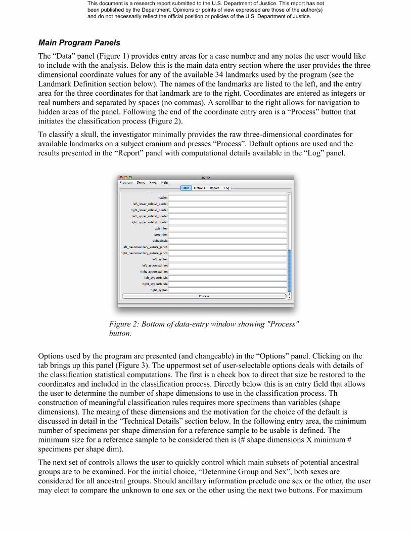
Main Program PanelsThe “Data” panel (Figure 1) provides entry areas for a case number and any notes the user would like to include with the analysis. Below this is the main data entry section where the user provides the three dimensional coordinate values for any of the available 34 landmarks used by the program (see the Landmark Definition section below). The names of the landmarks are listed to the left, and the entry area for the three coordinates for that landmark are to the right. Coordinates are entered as integers or real numbers and separated by spaces (no commas). A scrollbar to the right allows for navigation to hidden areas of the panel. Following the end of the coordinate entry area is a “Process” button that initiates the classification process (Figure 2).
To classify a skull, the investigator minimally provides the raw three-dimensional coordinates for available landmarks on a subject cranium and presses “Process”. Default options are used and the results presented in the “Report” panel with computational details available in the “Log” panel.
Options used by the program are presented (and changeable) in the “Options” panel. Clicking on the tab brings up this panel (Figure 3). The uppermost set of user-selectable options deals with details of the classification statistical computations. The first is a check box to direct that size be restored to the coordinates and included in the classification process. Directly below this is an entry field that allows the user to determine the number of shape dimensions to use in the classification process. Th construction of meaningful classification rules requires more specimens than variables (shape dimensions). The meaing of these dimensions and the motivation for the choice of the default is discussed in detail in the “Technical Details” section below. In the following entry area, the minimum number of specimens per shape dimension for a reference sample to be usable is defined. The minimum size for a reference sample to be considered then is (# shape dimensions X minimum # specimens per shape dim).
The next set of controls allows the user to quickly control which main subsets of potential ancestral groups are to be examined. For the initial choice, “Determine Group and Sex”, both sexes are considered for all ancestral groups. Should ancillary information preclude one sex or the other, the user may elect to compare the unknown to one sex or the other using the next two buttons. For maximum
Figure 2: Bottom of data-entry window showing "Process" button.
This document is a research report submitted to the U.S. Department of Justice. This report has not been published by the Department. Opinions or points of view expressed are those of the author(s) and do not necessarily reflect the official position or policies of the U.S. Department of Justice.

control, every combination of sex and group are listed at the bottom of the panel. The user is free to include (by checking) or exclude (by unchecking) any subset of the groups listed. The actual groups to which the unknown is compared, though, is a function of the available reference material, the number of shape dimensions chosen, the minimum number of specimens per shape dimension, and the actual landmarks for which coordinates are available.
Pressing the “Process” button on the “Option” panel initiates the classification process. When complete, the results are reported in the “Output” window (Figure 4).
This particular output is for some data provided with the program for demonstration purposes. The output first shows the case number (if provided by the user) and associated notes. A listing of the
Figure 3: The program "Option" panel.
Figure 4: The program "Output" panel showing classification results.
This document is a research report submitted to the U.S. Department of Justice. This report has not been published by the Department. Opinions or points of view expressed are those of the author(s) and do not necessarily reflect the official position or policies of the U.S. Department of Justice.

parameter values used by the program appears next. The first is the method used in constructing the classification function. This is currently fixed at “CVA” and described in detail in the “Technical Details” section. This is followed by the specified number of shape dimensions, minimum sample size per shape dimension, the minimum sample size allowable for inclusion in the analysis (the product of the previous two values), the setting for the group/sex or sex only directive, and the reference data base being used in the classification. (The latter only changes in the current version of the program only for the cross-validation test as explained in the “Technical Details” section.) The results of the classification are then summarized at the end of the report. The summary includes a list of those reference groups for which there were available data fitting the requirements of the programs parameter values. The number of individuals in each sample is given in parentheses next to the groups label. Next are three columns of numbers including the Mahalanobis squared distance of the (superimposed) unknown to the group mean, the posterior probability of membership in that group as opposed to others that were considered, and the typicality of the unknown specimen should it actually be a member of that group. In the case shown, the unknown was (correctly) assigned to the African-American male reference group consisting of 139 individuals with the same landmarks as the unknown. Its posterior probability of 0.8910 for the chosen group is far higher that any other group, and it appears to be a rather typical (p=0.1494) shape for an African-American male – far more so that for other possibilities.
The program “Log” window is for output of technical details that could aid in troubleshooting. The information here provides a more detailed view of the processing than necessary or desirable for the “Report” window. The program first checks each coordinate for each landmark. Each landmark for which data is provided must have three elements that can be translated to decimal values. If not values are provided, the point is marked as “*missing*”. Missing data are acceptable, but data provided for any landmark must be complete. The scroll bar on the right of the window allows the user to scroll down through the listing. The parameters in effect for the classification are listed as in the “Report” window. Information is then provided indicating that the reference data base has been opened and the objects matching the groups/sexes selected by the user extracted. These specimens are the filtered to remove any specimen that does not have coordinates for the same landmarks as the unknown. After that, all missing landmarks in the unknown are deleted from the reference samples. Subsequent information shows the progress of the Generalized Procrustes superimposition of the reference samples
Figure 5: The program "Log" window.
This document is a research report submitted to the U.S. Department of Justice. This report has not been published by the Department. Opinions or points of view expressed are those of the author(s) and do not necessarily reflect the official position or policies of the U.S. Department of Justice.

and the superimposition of the unknown onto the resulting grand mean. At this point, the data have been transformed so that the unknown can be compared to each possible group as described in the “Technical Details” section.
The Main MenuMost of the program interaction is through the main window panels. However, the main menu provides access to a number of specialized program features and information. These items are discussed below.
Program: The “Program” menu item (Figure 6) provides selections to “Read Data” from a file, “Save Data” to a file, and “Clear Data” from the data panel. Reading and saving data involve a very simple and rigid format. The saved file will have exactly thirty-five lines containing either nothing or the values entered for that landmark in its data entry field. Note that the are only 34 landmarks listed in the data entry field. One has been hidden due to reliability issues, but is still in the reference data base and must be accounted for in the data (as missing). So, it must be in the saved data file. A file to be read in must have the exact same format. Finally, the “Exit” item closes the window and exits the program.
Demo: The “Demo” menu item provides some sample data for easy demonstration of the program. The choices are “African-American Male”, “European-American Female”, and “European Male” (Figure 7). Selecting any one of these representative configurations choice will cause the landmark coordinates for the associated specimen to be entered into the landmark coordinate entry fields in the “Data” panel. The user can then click on the “Process” button to see the results of the classification of that individual.
X-val: The “X-val” menu item provides access to the cross-validation tests used in the development of this program. It was originally included for debugging and testing purposes, but was made accessible to end users as it provides insight into the operation, capabilities, and accuracy of the program. In the cross-validation process, each specimen is removed from the reference database and treated as the unknown. Classification functions are then constructed based on the remaining specimens and used to classify the excluded individual. In this way, an good estimate of classification accuracy can be obtained since the specimen being classified was not involved in the construction of the classification rule. See “Technical Details” for more information. The two choices under this item refer to two
Figure 6: The "Program" menu items.
Figure 7: The "Demo" menu items.
This document is a research report submitted to the U.S. Department of Justice. This report has not been published by the Department. Opinions or points of view expressed are those of the author(s) and do not necessarily reflect the official position or policies of the U.S. Department of Justice.
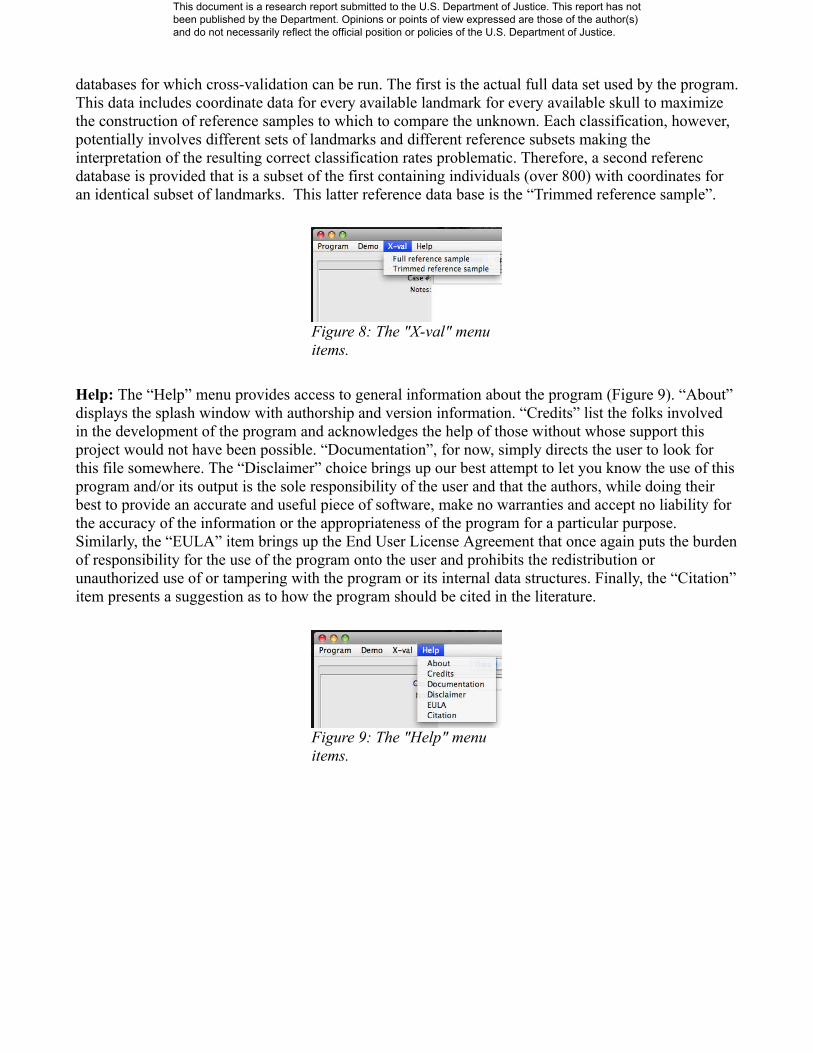
databases for which cross-validation can be run. The first is the actual full data set used by the program. This data includes coordinate data for every available landmark for every available skull to maximize the construction of reference samples to which to compare the unknown. Each classification, however, potentially involves different sets of landmarks and different reference subsets making the interpretation of the resulting correct classification rates problematic. Therefore, a second referenc database is provided that is a subset of the first containing individuals (over 800) with coordinates for an identical subset of landmarks. This latter reference data base is the “Trimmed reference sample”.
Help: The “Help” menu provides access to general information about the program (Figure 9). “About” displays the splash window with authorship and version information. “Credits” list the folks involved in the development of the program and acknowledges the help of those without whose support this project would not have been possible. “Documentation”, for now, simply directs the user to look for this file somewhere. The “Disclaimer” choice brings up our best attempt to let you know the use of this program and/or its output is the sole responsibility of the user and that the authors, while doing their best to provide an accurate and useful piece of software, make no warranties and accept no liability for the accuracy of the information or the appropriateness of the program for a particular purpose. Similarly, the “EULA” item brings up the End User License Agreement that once again puts the burden of responsibility for the use of the program onto the user and prohibits the redistribution or unauthorized use of or tampering with the program or its internal data structures. Finally, the “Citation” item presents a suggestion as to how the program should be cited in the literature.
Figure 8: The "X-val" menu items.
Figure 9: The "Help" menu items.
This document is a research report submitted to the U.S. Department of Justice. This report has not been published by the Department. Opinions or points of view expressed are those of the author(s) and do not necessarily reflect the official position or policies of the U.S. Department of Justice.

INSTALLATION AND SYSTEM REQUIREMENTS
System Requirements A computer system with an operating system for which the requisite Java.
Java 5 (JDK 1.5.x) or higher ( http://www.java.com )
The latest version of 3D-ID available from http://www.3d-id.org
3D-ID is a cross-platform program written in Java. It should run on any system for which an appropriate Java version is available. Mac OS X 10.5, for instance, comes with Java 2 Standard Edition 5.0 (JDK 1.5.x). The latest Java Virtual Machine for all supported operatings systems, e.g., Mac OS X, MS Windows, and Linux, can be downloaded from the Sun site: http://www.java.com Your local computer support person can help if you have problems.
Basic InstallationIf you have an appropriate and functioning Java virtual machine on your computer, installation of 3D-ID is trivial – simply download the latest 3d_id.jar file from http://3d_id.jar into a desired directory or onto your desktop. Running the program should simply involve clicking or double-clicking that files's icon.
Trouble ShootingIf you can run Java programs on a reasonably up-to-date operating system, you should have no problems running 3D-ID. If you do, the following can guide your troubleshooting efforts, but it may be a good idea to seek the help of a specialist familiar with your operating system and Java. The information is presented in generic terms. Details may vary slightly depending upon your operating system.
Besides clicking the program icon, you can invoke it from the command line. This affords you the opportunity to see any diagnostic messages should there be a problem. Familiarity with this mode of execution is assumed in subsequent discussions of tracking down Java installation problems. Once all problems are sorted, you can setup an icon with modified parameters to run the program directly from the desktop or other convenient location.
The basic idea is a) open a command-line window, b) change to the directory where the programs are stored, and c) have the Java Runtime Environment run the program using:
java -jar 3d_id.jar
Check to confirm that the program starts and you get no serious error messages. If the program does not run, you should ensure your Java installations are correct by typing, say:
java -version
The output should look something like this:
This document is a research report submitted to the U.S. Department of Justice. This report has not been published by the Department. Opinions or points of view expressed are those of the author(s) and do not necessarily reflect the official position or policies of the U.S. Department of Justice.
user:~user$ java -versionjava version "1.5.0_20"Java(TM) 2 Runtime Environment, Standard Edition (build 1.5.0_20-b02-315)Java HotSpot(TM) Client VM (build 1.5.0_20-141, mixed mode, sharing)user:~user$
The key features here are a) you got actual Java output and b) the version number is greater than 1.5 (=J2SE 5).
3D-ID has a surprisingly small memory footprint, but in some very restricted environments one could run into memory problems. In that case, one run-time parameter you may need to adjust is memory allocation. Maximum memory available to a Java program is set at startup and varies depending upon platform and implementation. You can use the -Xmx parameter to allocated a specific amount of memory that will be available to the program. For development of more memory intensive programs, I have had good success with 768 megabytes. In this case, the appropriate command line would look like:
java -Xmx768M -jar 3d_id.jar
You can add this parameter to the command line if you set up a link to the program to run from the Desktop or other location.
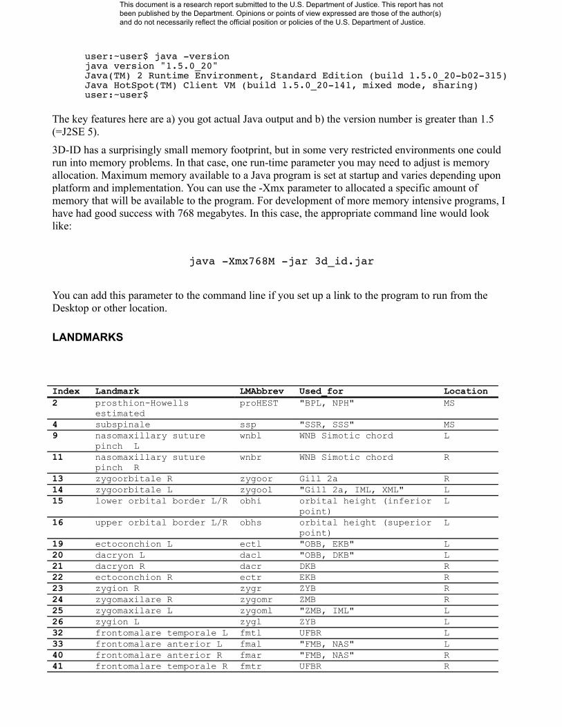
LANDMARKS
Index Landmark LMAbbrev Used_for Location2 prosthion-Howells
estimatedproHEST "BPL, NPH" MS
4 subspinale ssp "SSR, SSS" MS9 nasomaxillary suture
pinch Lwnbl WNB Simotic chord L
11 nasomaxillary suture pinch R
wnbr WNB Simotic chord R
13 zygoorbitale R zygoor Gill 2a R14 zygoorbitale L zygool "Gill 2a, IML, XML" L15 lower orbital border L/R obhi orbital height (inferior
point)L
16 upper orbital border L/R obhs orbital height (superior point)
L
19 ectoconchion L ectl "OBB, EKB" L20 dacryon L dacl "OBB, DKB" L21 dacryon R dacr DKB R22 ectoconchion R ectr EKB R23 zygion R zygr ZYB R24 zygomaxilare R zygomr ZMB R25 zygomaxilare L zygoml "ZMB, IML" L26 zygion L zygl ZYB L32 frontomalare temporale L fmtl UFBR L33 frontomalare anterior L fmal "FMB, NAS" L40 frontomalare anterior R fmar "FMB, NAS" R41 frontomalare temporale R fmtr UFBR R
This document is a research report submitted to the U.S. Department of Justice. This report has not been published by the Department. Opinions or points of view expressed are those of the author(s) and do not necessarily reflect the official position or policies of the U.S. Department of Justice.

45 glabella glb GOL MS48 bregma brg "FRC, BBH, PAC, PAF,
PAS, etc."MS
50 lambda lam "PAC, PAF, PAS" MS51 opisthocranion (GOL) opg GOL MS53 asterion L astl ASB MS57 mastoideale L mastl MDH L62 mastoideale R mastr MDH R64 asterion R astr ASB L68 opisthion ops FOL MS69 basion bas "between hypobasion and
endobasion. BBH,BNL,"MS
72 ectomolare L ecml MAB L74 ectomolare R ecmr MAB R75 alveolon (rubber band) alv MAL MS
This document is a research report submitted to the U.S. Department of Justice. This report has not been published by the Department. Opinions or points of view expressed are those of the author(s) and do not necessarily reflect the official position or policies of the U.S. Department of Justice.

Illustration 10: Landmarks used by 3D-ID: anterior view.
This document is a research report submitted to the U.S. Department of Justice. This report has not been published by the Department. Opinions or points of view expressed are those of the author(s) and do not necessarily reflect the official position or policies of the U.S. Department of Justice.

Illustration 11: Landmarks used by 3D-ID: lateral view.
This document is a research report submitted to the U.S. Department of Justice. This report has not been published by the Department. Opinions or points of view expressed are those of the author(s) and do not necessarily reflect the official position or policies of the U.S. Department of Justice.

Illustration 12: Landmarks used by 3D-ID: posterior view.
This document is a research report submitted to the U.S. Department of Justice. This report has not been published by the Department. Opinions or points of view expressed are those of the author(s) and do not necessarily reflect the official position or policies of the U.S. Department of Justice.

Illustration 13: Landmarks used by 3D-ID:inferior view.
This document is a research report submitted to the U.S. Department of Justice. This report has not been published by the Department. Opinions or points of view expressed are those of the author(s) and do not necessarily reflect the official position or policies of the U.S. Department of Justice.

TECHNICAL DETAILSShape is defined as the geometric properties of an object that are invariant to location, orientation, and size, and form is defined as shape + size (Slice et al. 1996). Specifying an invariance to location and orientation seems straightforward as one generally does not want the measurements under consideration to vary with where the object is measured or how it is rotated. Size, on the other hand, often tends to dominate variation in biological samples and may or may not contribute meaningful signal in doing so. Therefore, morphometrics analysis focuses on the isolation of shape variation as per the above definition while factoring out and sequestering a size component that may or may not be considered alone or with shape (form) depending upon the investigators goals and insight.
Traditional (curvi-)linear distances and angular measurements vary in their appropriateness as shape variables. Distances between points on an object are, in fact, invariant to the location and orientation of the object from which they are obtained, but they carry with them size information. This can be partially remedied by the construction of “indices” that are of the form, I = 100 * (d1/d2). This records one measured distances relative to another on the same specimen and removes size from between-specimen comparisons. Angles are invariant to location, orientation, and size, and are, thus, proper shape variables.
Figure XXXX illustrates part of the problem with traditional measurements in morphometric analysis. The size dependence of the distances between nasion (n) and basion (ba) and the distance from basion to prosthion (pr) can be addressed by the construction of the gnathic index, Ig = 100 x (d(n-ba)/d(ba-pr)). This, however, introduces the complex characteristics of ratios into the problem and still fails to fix the relationship between nasion and prosthion. Adding the angle between the two segments addresses that problem, but mixes units in the data. Adding a second second index, Ig(n-pr) 100 x (d(n-pr)/d(ba-pr)) works, but as more and more points are considered the requisite number of carefully chosen distances to capture all of the geometry rapidly proliferates. The example is two-dimensional, but these considerations apply with equal force in three.
This document is a research report submitted to the U.S. Department of Justice. This report has not been published by the Department. Opinions or points of view expressed are those of the author(s) and do not necessarily reflect the official position or policies of the U.S. Department of Justice.

One approach to the above problem taken by GM is to focus on the analysis of the coordinates of anatomical points instead of the distances between them or the angles they form. Coordinates, though, vary as a function of the location of an individual specimen with respect to more-or-less arbitrary digitizing axes used for data collection. This requires some pre-processing of the data to construct proper shape variables, but they retain all geometric information that could be collected from distances and angles defined by the same points. That pre-processing step involves the registration of the configurations of landmarks for all specimens into a common coordinate system using a least-squares estimation of location and orientation parameters and a reasonable size standardization. This approach in which data from individual specimens are fit to an iteratively computed mean configuration is called Generalized Procrustes Analysis (GPA). After superimposition, the landmarks can be subjected to familiar multivariate procedures including discrimination and classification methods. Since all intrinsic geometric information is retained, graphical reconstructions in physical space of multivariate statistical procedures can be done, though that is less useful in the current application.
Illustration 14: Traditional measurements based on anatomical landmarks. Landmarks are prosthion (pr), nasion (n), bregma (b), lambda (l), inion (i), opisthion (o), and basion (ba). Measurements are the distances between nasion and basion , d(n-ba), and between prosthion and basion, d(pr-ba). Theta(n-ba-pr) is the angle formed at basion by the three points.. See text for details.
This document is a research report submitted to the U.S. Department of Justice. This report has not been published by the Department. Opinions or points of view expressed are those of the author(s) and do not necessarily reflect the official position or policies of the U.S. Department of Justice.

3D-ID implements this approach to help characterize unknown human remains (specifically, cranial remains at this time). To do this, the user provides the program with three-dimensional coordinates of a subset of the landmarks described above. A reference database is then processed to extract appropriate reference samples, then the unknown is compared to the groups available in the reference sample to estimate group membership. Separate groupings are considered for each sex, but if sex can be determined by other means, the comparisons can be constrained to only male or female groups. The details of how this is accomplished is described below.
Initial Data Checking and Filtering: When the “Process” button is clicked, 3D-ID examines the entry for each listed anatomical point (landmark). It checks to make sure there are three numerically valid values for any landmarks for which data are provided. If no data are provided, it is assumed that value is missing or excluded from the unknown. Once the program determines that there exists an error-free subset of landmarks available for analysis, it turns its attention to the reference database. The reference database (currently containing over 1000 specimens) is scanned and any object that does not contain at least the landmarks specified for the reference is deleted. This results in an unknown with some number of valid 3D coordinates for some number of landmarks and the remainder marked as missing and a reference data base within which all objects have values for the non-missing ones provided for the reference.
All landmarks marked as missing in the unknown are then deleted from the data structure for the unknown and from all remaining reference specimens. The result is a reference skull with 3D coordinates provided from some subset of landmarks and a reference set consisting of all members of the original reference database edited so as to have the same landmarks as the unknown. At this point, all objects, whether unknown or reference, have the same number of landmarks and no missing data.
Finally, the specified number of shape dimensions to use and the minimum number of specimens per shape dimension are used to compute the minimal sample size for any reference population (the product of the two values). The reference data are scanned once again, and any populations with less than this number of specimens is removed from consideration.
Procrustes Analysis: The entirety of the reference data are then subjected to a Generalized Procrustes Analysis. This is an iterative procedure that translates and rotates the sum of squared deviations of
Illustration 15: Anatomical landmark positions encoded as Cartesian coordinates.
This document is a research report submitted to the U.S. Department of Justice. This report has not been published by the Department. Opinions or points of view expressed are those of the author(s) and do not necessarily reflect the official position or policies of the U.S. Department of Justice.

individual landmarks to their homologues on an iteratively computed mean, or reference, configuration. Prior to iterating, the optimal translation is obtained once and for all by mean centering every individual configuration of landmarks – the sum of coordinate values for any one configuration equals zero. The iteration begins by the selection of any configuration of landmarks (in this case the first in the reference sample) as an estimate of the mean, fitting the data to that, recomputing the mean, and repeating until convergence. Optimal rotation at each of these steps is achieved by multiplying the mean-centered configuration, Xi, where Xi is a p landmarks by k dimension matrix for the ith configuration, by:
Hi=VSU t
Here, V and U are orthonormal rotation matrices computed by singular value decomposition as:
Xreft Xi=U V t
The matrix Xreft is the current estimate of the reference configuration. The matrix S is a diagonal
matrix of ones with the same sign as the corresponding diagonal elements of Σ and ensures the rotation is rigid and does not stretch the configuration to achieve a reduction in the sum of squares (Σ will do that).
Scaling occurs once-and-for-all with the translation prior to iteration, but is not least-squares based. Instead, configurations are scaled so that the square root of the sum of squared deviations of all the points from their centroid is 1.0. This measure, called Centroid Size, has certain logical and optimality properties that recommend it here, and its use results in all specimens being scaled to the same (CS=1.0) sized, thus removing size variability (as defined by CS) from the reference data.
Further details and discussion of these procedures can be found in Slice (2005, 2007) and include appropriate citations.
Dimension Reduction: Once subject to GPA, the reference data have landmark coordinates in a common coordinate system that can be used as components of shape and subjected to various multivariate procedures. However, the translation, rotation, and scaling forces the covariance matrix to be singular as seven (for 3D data) degrees of freedom of variation are lost from the data. Also, as more-and-more landmarks are collected, the number of variables can equal or exceed the number of specimens – another situation guaranteeing singular covariance matrices. In general, singular covariances matrices are always encountered in GPA and can cause problems for multivariate analyses. So, steps must be taken to either ensure nonsingularity of the covariance matrix or handle it appropriately. 3D-ID does both.
A common procedure when faced with singular covariances matrices is to use Principal Components Analysis (PCA) to pull out a variance maximizing subset of linear combinations of the original variables that help guarantee a covariance matrix of full rank. This is done here through the “Shape Dimensions” program parameter. This allows the user to specify (in this version of the program) the number of PCs from the superimposed data to use in the subsequent operations. This value can range from one (the minimum) to 34 landmarks X 3 dimensions = 102 should coordinates be available for all landmarks.
It should be noted that once a reduced number of data PCs have been selected for analysis that any subsequent p-values are suspect. The PCs extract combinations of the variables with greatest variance, and this may or may not be driven by the differences inspected by statistical tests. A usual case it to deflate the p-values (making them look more significant) when group differences contribute a great deal to the sample variation. This is not that great an issue for 3D-ID as the focus is maximizing correct classification rates and not estimating actual probabilities.
This document is a research report submitted to the U.S. Department of Justice. This report has not been published by the Department. Opinions or points of view expressed are those of the author(s) and do not necessarily reflect the official position or policies of the U.S. Department of Justice.

The 3D-ID default value for the number of shape dimensions is currently 53. This was chosen as the value that for the current reference data with a minimum number of one specimen per dimension correctly cross-classified the greatest number of individuals in the reference data set.
Note, too, that the number of shape dimensions interacts with the minimum number of specimens per shape dimension parameter to affect the analysis. There must be the minimum number of specimens specified for each shape dimensions used. Thus, as the number of shape dimensions increases smaller samples are excluded from the analysis. With the current default, this reduces the reference population to possible classifications of African American, European, and European males and females. Thus, users are encouraged to try various alternative minimum numbers of shape dimensions and consider unknown classifications in light of cross-validation results with the same parameters.Discriminant Analysis: The classification routine implemented in the current version of the program involves assignment of the unknown to the group whose from which the unknown has the smallest Mahalanobis squared distance. This distance is computed as:
Di2= x unknown− x i
t Spooled−1 xunknown− x i
The Di2 is the squared Mahalanobis distance of the unknown to the ith group mean. The Spooled
-1 is the pooled, within covariance matrix for the data in the reduced space of the total sample PCs specified by the “Shape Dimension” parameter. To guard against problems caused by singularities in Spooled, 3D-ID uses, instead of the standard matrix inverse, the Moore-Penrose inverse, Spooled
+ , computed from the singular-value decomposition of Spooled. This also guards against very small, but nonzero, values that can destabilize the matrix inversion.
Note that the xs are now vectors instead of matrices with rows representing points and columns their coordinates. Once the GPA process is completed, the data are converted to vectors initially with dimension nLandmarks X nDimensions. The reference data are organized in a matrix of with rows for every specimen and columns for every dimension for every landmark.
As implemented, the reference data are projected into the reduced space of the PCs retained according to the “Shape Dimension” parameter. This is done by multiplying the (mean-centered) data matrix on the right by the first “minimum Shape Dimensions” eigenvectors of S. After this, the pooled, within group covariance matrix is computed by pooling the deviations of members of all groups from their own group mean. This matrix, Spooled, forms the basis for the computation of the Mahalanobis squared distances described above, though the exact computation is a little different.
The above formula shows how to transform the distance between a specimen (the unknown) and a group mean into a Mahalanobis squared distance by use of the inverse, pooled covariance matrix. The same result can be obtained by transforming the space of all specimens by this same matrix and, then, computing Euclidean distances in that space. This is what is done in 3D-ID. First, the unknown is fit to the grand reference mean using an Ordinary Procrustes Analysis (a non-iterative implmentation of the above that fits one configuration to another specificed configuration instead of an iteratively computed mean). Then, it is projected into the reduced space of the reference sample using the same eigenvectors as used for the reference data. This transformed unknown and all of the group means in this reduced space are then mapped into a transformed space by multiplication by Spooled
+ . Squared, Euclidean distances between the unknown and each group mean are then computed, and these are the familiar Mahalanobis squared distances.
The Mahalanobis squared distances are standardized distances accounting for the covariance structure of the data, but may not look familiar as standard deviations. This is because these are distances in a multidimensional space where each dimension can add to the value of the distance. Additional steps
This document is a research report submitted to the U.S. Department of Justice. This report has not been published by the Department. Opinions or points of view expressed are those of the author(s) and do not necessarily reflect the official position or policies of the U.S. Department of Justice.

must be taken to convert them into a probability of group membership (even in light of the warning about using PCs for such previously mentioned).
Assignment of the Unknown: The suggested assignment of the unknown is to that of the available groups for which the unknown has the smallest Di
2 . This is not necessarily as clear cut a statement as one might hope, so several other diagnostic measures are provided to aid in the evaluation of the suggested assignment following Campbell (1984).
The suggested assignment is based on the lowest Di2 , but the distances to other groups might be
fairly similar. To help gauge the strength of the suggestion in this regard, a “posterior probability” is provided for each group. This measures the relative closeness of the unknown to each group. In the most clear cut case, there will be one very high value associated with the suggested assignment with values for the other groups near zero. In a more ambiguous case, one or more groups may have lower, but similar, posterior probabilities to that of the suggested assignment. This indicates that while the unknown was slightly more similar to the recommended group, it was nearly as similar to one or more other groups. In such cases, the recommended assignment should be viewed with caution.
The proper computation of the poster probabilities for multivariate data should take unequal sample sizes and estimated parameters into account. Assuming equal prior probabilities of being in any of the reference groups, the posterior probability of membership in the ith group is:
Pr xunknown i=f xunknown i
∑j=1
g
f xunknown j
Here, f() is the probability density function for the unknown and the group specified in the subscript. With unequal sample sizes and estimated means and covariance structures, this the leads to:
f x unknown i=−v/2 n f 1/ 2 n f−v1/2 ∣ni1n f
niSpooled∣
−1/21 n i D i2
n f n i1 −n f1 /2
In this equation, v is the dimensionality of the space of the reference data (probably reduced by PCA),
ni is the size of the ith reference group, n f=∑i=1
g
ni−1 , and Γ() is the gamma function. Again, the
generalized inverse is used by the program to address singularities and avoid instabilities.
The second diagnostic measure provided by the program is a “typicality” measure. This is simply the probability of an observation being as far or farther away from the mean as the unknown for a particular group. Typicality measures how likely is it that the unknown came from a particular population at all. For instance, an unknown will always be suggested as belonging to one of the available reference groups, but typicality measures how likely is that to be true for any given population. That is, the unknown could be suggested for membership in one (the closest) population, but still be so different that the probability of actually finding a specimen that different from the population is small. Again, in such cases, the suggested assignment should be taken with an appropriate degree of skepticism. Typicality is computed by finding the probability of:
n f −v1 ni
v n f n i1 Di
2
for an F distribution with v and nf – v +1 degrees of freedom, F(v, nf – v + 1). In general, then, the program will suggest an assignment to the group whose mean is closest in the
This document is a research report submitted to the U.S. Department of Justice. This report has not been published by the Department. Opinions or points of view expressed are those of the author(s) and do not necessarily reflect the official position or policies of the U.S. Department of Justice.
Mahalanobis sense to the unknown. Posterior probabilities can be used to assess how strong the evidence for this assignment is versus other reference groups. The typicality can be used to assess how likely the unknown is to have come from a particular population regardless of how much closer it is to it than the other populations or how much that difference is similar to other such differences. In all cases, the selection of program parameters chosen by the user will effect both the groups included in the analysis both directly, through selection of different groups for inclusion, and indirectly, by requiring groups to have sufficient sample size to meet the shape dimension restrictions.
REFERENCES
Bookstein, F. L. 1991. Morphometric tools for landmark data: geometry and biology. Cambridge Univ Press.
Campbell, N. A. 1984. Some aspects of allocation and discrimination. In Multivariate Statistical Methods in Physical Anthropology (G. N. van Vark and W. W. Howells, eds.), 177-192. D. Reidel Publishing.
Giles, E. 1964. Sex Determination by Discriminant Function Analysis of the Mandible. American Journal of Physical Anthropology 22: 129-135.
Giles, E. and O. Elliot. 1962. Race Identification from Cranial Measurements. Journal of Forensic Sciences 7: 147-157.
Jantz, RL, and PH Moore-Jansen. 1988. A Data Base for Forensic Anthropology: Structure, Content and Analysis. Report of Investigations No. 47. Department of Anthropology, The University of Tennessee.
Lynch, JM, CG Wood, and SA Luboga. 1996. Geometric morphometrics in primatology: Craniofacial variation in Homo sapiens and Pan troglodytes. Folia Primatologica 67(1): 15-39.
Moore-Jansen, PH, SD Ousley, and RL Jantz. 1994. Data Collection Procedures for Forensic Skeletal Material. 3rd ed. University of Tennessee Forensic Anthropology Series. Knoxville, Tenneessee.
Rohlf, F. J. and L. F. Marcus. 1993. A Revolution in Morphometrics. Trends in Ecology and Evolution 8(4): 129-132.
Ross, A. H., A. H. McKeown, and L. W. Konigsberg. 1999. Allocation of crania to groups via the "new morphometry". Journal of Forensic Sciences 44(3): 584-587.
Slice, D. E. 2005. Modern Morphometrics in Physical Anthropology. Springer.
Slice, D. E. 2007. Geometric morphometrics. Annual Review of Anthropology 36: 261-281.
This document is a research report submitted to the U.S. Department of Justice. This report has not been published by the Department. Opinions or points of view expressed are those of the author(s) and do not necessarily reflect the official position or policies of the U.S. Department of Justice.

Slice, D. E., F. L. Bookstein, L. F. Marcus, and F. J. Rohlf. 1996. A glossary of geometric morphometrics. In Advances in Morphometrics, 284:531-551. NATO ASI Series Series A: Life Sciences. New York: Plenum Press.
Ubelaker, D., A. Ross, and S. M. Graver. 2002. Application of Forensic Discriminant Functions to a Spanish Cranial Sample. Forensic Science Communications 4, no. 3. http://www.fbi.gov/hq/lab/fsc/backissu/july2002/ubelaker1.htm.
This document is a research report submitted to the U.S. Department of Justice. This report has not been published by the Department. Opinions or points of view expressed are those of the author(s) and do not necessarily reflect the official position or policies of the U.S. Department of Justice.
Related Documents