A. Borovkov, A. Gaev, A. Nemov, O. Neubauer, A. Panin and JET EFDA contributors EFDA-JET-CP(06)04-04 3-D Finite Element Electromagnetic and Stress Analyses of the JET LB-SRP Divertor Element (Tungsten Lamella Design)

Welcome message from author
This document is posted to help you gain knowledge. Please leave a comment to let me know what you think about it! Share it to your friends and learn new things together.
Transcript

A. Borovkov, A. Gaev, A. Nemov, O. Neubauer, A. Paninand JET EFDA contributors
EFDA-JET-CP(06)04-04
3-D Finite Element Electromagneticand Stress Analyses of the JET
LB-SRP Divertor Element(Tungsten Lamella Design)

“This document is intended for publication in the open literature. It is made available on theunderstanding that it may not be further circulated and extracts or references may not be publishedprior to publication of the original when applicable, or without the consent of the Publications Officer,EFDA, Culham Science Centre, Abingdon, Oxon, OX14 3DB, UK.”
“Enquiries about Copyright and reproduction should be addressed to the Publications Officer, EFDA,Culham Science Centre, Abingdon, Oxon, OX14 3DB, UK.”
3-D Finite Element Electromagneticand Stress Analyses of the JET
LB-SRP Divertor Element(Tungsten Lamella Design)
A. Borovkov1, A. Gaev1, A. Nemov1, O. Neubauer2, A. Panin2
and JET EFDA contributors*
1Computational Mechanics Laboratory (CompMechLab), St.Petersburg State Polytechnical University,St.Petersburg, Russia
2Institut für Plasmaphysik, Forschungszentrum Jülich, Association EURATOM/FZJ,Trilateral Euregio Cluster, D52425 Jülich, Germany
* See annex of J. Pamela et al, “Overview of JET Results”, (Proc.�20th IAEA Fusion Energy Conference, Vilamoura, Portugal (2004).
Preprint of Paper to be submitted for publication in Proceedings of theSOFT Conference,
(Warsaw, Poland 11th - 15th September 2006)

.

1
ABSTRACT
Within the ITER-like wall project at JET, the original plasma facing tiles in the divertor region
made of carbon fibre composite (CFC) will be replaced by tungsten coated CFC and bulk tungsten
tiles. The main constraint of the bulk tungsten concept is to accommodate the power and energy
handling requirements, the electromagnetic (EM) forces and the mechanical requirements of the
existing remote handling system.
Through a number of intermediate design options the “lamella” option has been developed,
consisting of plasma facing tiles, an inconel wedge holding the tiles and an inconel interface plate
attaching the wedge to the JET CFC base plate. In order to minimize eddy currents the wedge must
be equipped with slits and the W-lamellae are isolated from each other. Defined electrical contacts
from the lamellae via the wedge to the base plate define the path of the halo currents. The pairs of
lamellae are isolated from each other by insulating spacers and tie rods keep the stack of tungsten
lamellae and ceramic coated spacers together. Eight tungsten lamella stacks are attached to the
wedge via eight “rails”. This paper reports on calculation of the electromagnetic (EM) loads in the
block components and of the stress-strain state of the block, subjected to the worst combination of
EM loads, by 3-D Finite Element (FE) electromagnetic and stress analyses.
As a result of these studies the level of initial pre-tension of the joint elements has been checked
against possible detachment. The bending of the load bearing components has proved to be
moderately low compared with the structural material allowable limits.
INTRODUCTION
The Joint European Torus (JET) [1] is the largest tokamak in the world and an essential part of the
European and world wide Fusion Programme. The plasma is created in a toroidally shaped vacuum
vessel, confined by magnetic fields and the power is exhausted mainly in the divertor. So far the
plasma-facing material in the divertor and main chamber is CFC. The ITER-like Wall (ILW) project
was initiated at JET with the goal of gaining experience with ITER material choices, Beryllium in the
main chamber and tungsten in the divertor. For the ILW project, the whole divertor region will be
replaced by a tungsten coated CFC and with solid tungsten tiles on areas wetted by the outer divertor
leg in the ITER-like magnetic configuration (Load Bearing Septum Replacement Plate (W-LBSRP)).
The research concentrated on the “lamella” design of the JET Load Bearing Septum Replacement
Plate (W-LBSRP) divertor tile block. The location of the W-LBSRP block in the torus is shown in
Fig.1. The tiles are subjected to high thermal loads and large electromagnetic (EM) loads. The aim of
this study is to evaluate the structural behaviour of the LBSRP eddy current loads due to the magnetic
field derivatives, toroidal current and two scenarios for the halo current loads.
1. DESIGN DESCRIPTION
Each divertor block consists of three main structural parts: eight plasma facing tungsten tiles, an
inconel wedge holding the tiles and an inconel interface plate attaching the wedge to the JET
CFC base plate.

2
Each tile consists of a stack of tungsten lamellae. To minimize eddy currents in the tiles the pairs of
lamellae are isolated from each other by insulating spacers. Pre-loaded tie rods keep the stack of
tungsten lamellae and spacers together. To get rid of the large eddy current loops the inconel wedge
has eight narrow wings each holding one tile via a “rail”. The wedge is bolted to the inconel interface
plate with two pre-tensioned bolts. The adaptor plate is bolted to the base plate with two pre-
tensioned bolts.
Reliable electrical contact from lamellae via the wedge to the base plate is required for a defined
path of the halo currents. Fig.2 shows the design of the lamella block, developed in the IPP,
Forschungszentrum Juelich (FZJ). This design corresponds to the project at May 2006.
2. THE RESEARCH METHODOLOGY AND FINITE ELEMENT MODELS
DEVELOPING
Minimizing the EM loads is the major factor in the design. Due to complexity of the structure a
proper mathematical modeling should be used and FE analysis [2] is the leading numerical method
for the analysis of such complex structures.
Obtaining a coupled electromagnetic-structural solution for engineering problems is generally a
complex procedure and leads to serious difficulties. With regard to the quasi-stationary nature of
the problem the following algorithm is used:
- The EM analysis of the divertor block under eddy and halo current load is carried out for
different values of the magnetic field, field derivatives as well as for different halo current
options. The structural deformation is neglected.
- The integral forces and moments on the structural elements are derived from the solution.
The most critical cases of loading are selected for the structural analysis.
- The structural analysis of those systems that are loaded with electromagnetic forces in the
previous steps is made.
This means that the impact of the structural deformation on the current distribution is neglected.
The FE models used for electromagnetic and structural analysis often differ by the level of detail
and by the FE mesh (as for example in [3]). At present time, powerful computers allow nearly the
same global FE mesh for both electromagnetic and structural analyses. This approach makes the
transfer of the nodal forces from electromagnetic to structural models much easier.
To perform the electromagnetic and structural analyses, FE models of the W-LBSRP elements that
allow the direct transfer of the nodal forces from electromagnetic to structural analysis have been
developed. Despite some geometry simplifications, most of the basic features of the block elements
were taken into account (e.g. the real number of lamellas and spacers, their geometry, thicknesses
etc.). The FE analysis system ANSYS [4] was used for these studies.
The FE models of the tiles, wedge and adaptor plate are shown in Figs.3 and 4.
3
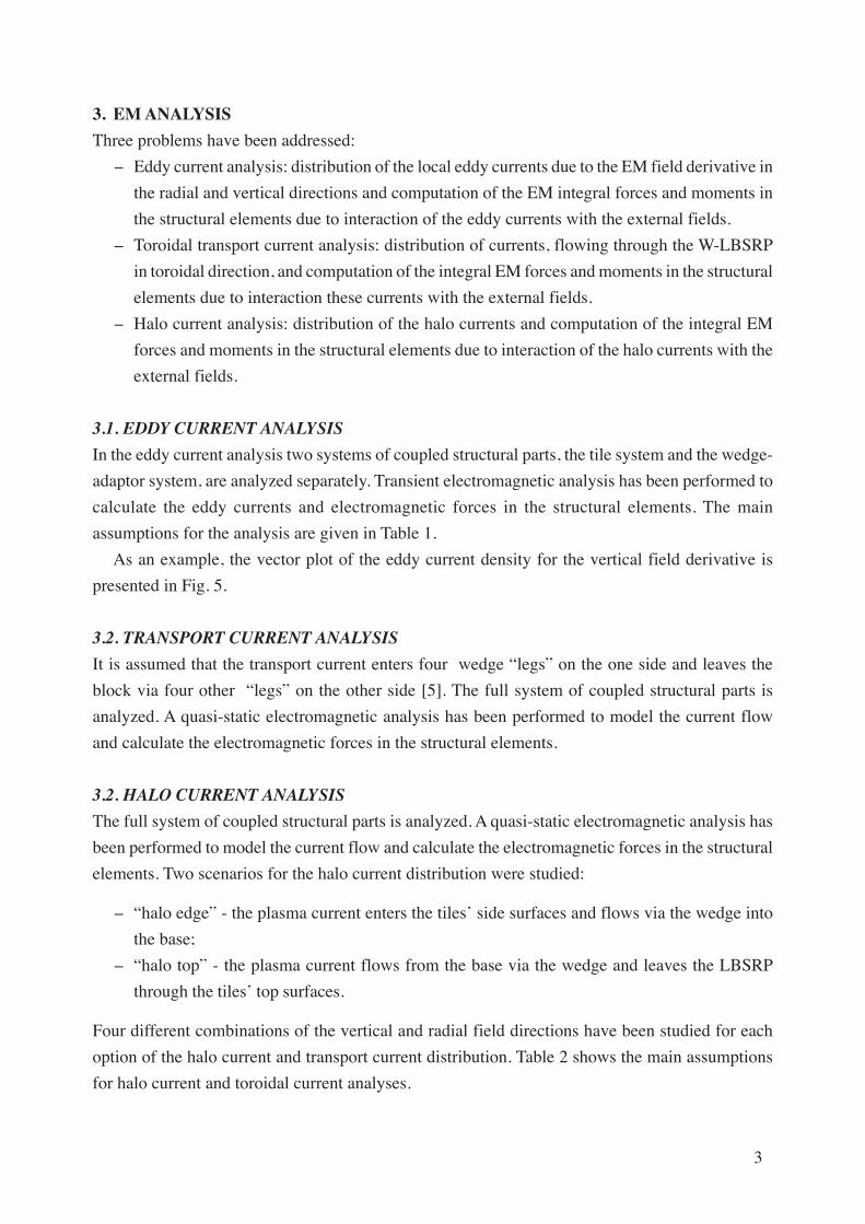
3. EM ANALYSIS
Three problems have been addressed:
- Eddy current analysis: distribution of the local eddy currents due to the EM field derivative in
the radial and vertical directions and computation of the EM integral forces and moments in
the structural elements due to interaction of the eddy currents with the external fields.
- Toroidal transport current analysis: distribution of currents, flowing through the W-LBSRP
in toroidal direction, and computation of the integral EM forces and moments in the structural
elements due to interaction these currents with the external fields.
- Halo current analysis: distribution of the halo currents and computation of the integral EM
forces and moments in the structural elements due to interaction of the halo currents with the
external fields.
3.1. EDDY CURRENT ANALYSIS
In the eddy current analysis two systems of coupled structural parts, the tile system and the wedge-
adaptor system, are analyzed separately. Transient electromagnetic analysis has been performed to
calculate the eddy currents and electromagnetic forces in the structural elements. The main
assumptions for the analysis are given in Table 1.
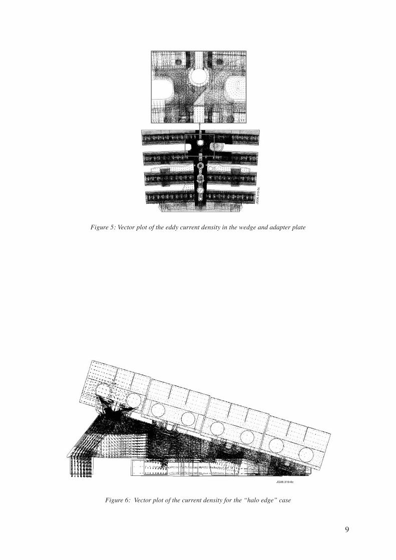
As an example, the vector plot of the eddy current density for the vertical field derivative is
presented in Fig. 5.
3.2. TRANSPORT CURRENT ANALYSIS
It is assumed that the transport current enters four wedge “legs” on the one side and leaves the
block via four other “legs” on the other side [5]. The full system of coupled structural parts is
analyzed. A quasi-static electromagnetic analysis has been performed to model the current flow
and calculate the electromagnetic forces in the structural elements.
3.2. HALO CURRENT ANALYSIS
The full system of coupled structural parts is analyzed. A quasi-static electromagnetic analysis has
been performed to model the current flow and calculate the electromagnetic forces in the structural
elements. Two scenarios for the halo current distribution were studied:
- “halo edge” - the plasma current enters the tiles’ side surfaces and flows via the wedge into
the base;
- “halo top” - the plasma current flows from the base via the wedge and leaves the LBSRP
through the tiles’ top surfaces.
Four different combinations of the vertical and radial field directions have been studied for each
option of the halo current and transport current distribution. Table 2 shows the main assumptions
for halo current and toroidal current analyses.
4
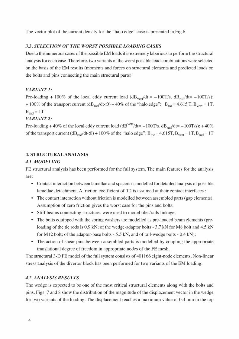
The vector plot of the current density for the “halo edge” case is presented in Fig.6.
3.3. SELECTION OF THE WORST POSSIBLE LOADING CASES
Due to the numerous cases of the possible EM loads it is extremely laborious to perform the structural
analysis for each case. Therefore, two variants of the worst possible load combinations were selected
on the basis of the EM results (moments and forces on structural elements and predicted loads on
the bolts and pins connecting the main structural parts):
VARIANT 1:
Pre-loading + 100% of the local eddy current load (dBvert/dt = -100T/s, dBrad/dt= -100T/s);
+ 100% of the transport current (dBrad/dt<0) + 40% of the “halo edge”; Btor = 4.615 T, Bvert = 1T,
Brad = 1T
VARIANT 2:
Pre-loading + 40% of the local eddy current load (dBvert/dt= -100T/s, dBrad/dt= -100T/s); + 40%
of the transport current (dBrad/dt<0) + 100% of the “halo edge”; Btor = 4.615T, Bvert = 1T, Brad = 1T
4. STRUCTURAL ANALYSIS
4.1. MODELING
FE structural analysis has been performed for the full system. The main features for the analysis
are:
• Contact interaction between lamellae and spacers is modelled for detailed analysis of possible
lamellae detachment. A friction coefficient of 0.2 is assumed at their contact interfaces ;
• The contact interaction without friction is modelled between assembled parts (gap elements).
Assumption of zero friction gives the worst case for the pins and bolts;
• Stiff beams connecting structures were used to model tiles/rails linkage;
• The bolts equipped with the spring washers are modelled as pre-loaded beam elements (pre-
loading of the tie rods is 0.9 kN; of the wedge-adaptor bolts - 3.7 kN for M8 bolt and 4.5 kN
for M12 bolt; of the adaptor-base bolts - 5.5 kN, and of rail-wedge bolts - 0.4 kN);
• The action of shear pins between assembled parts is modelled by coupling the appropriate
translational degree of freedom in appropriate nodes of the FE mesh.
The structural 3-D FE model of the full system consists of 401166 eight-node elements. Non-linear
stress analysis of the divertor block has been performed for two variants of the EM loading.
4.2. ANALYSIS RESULTS
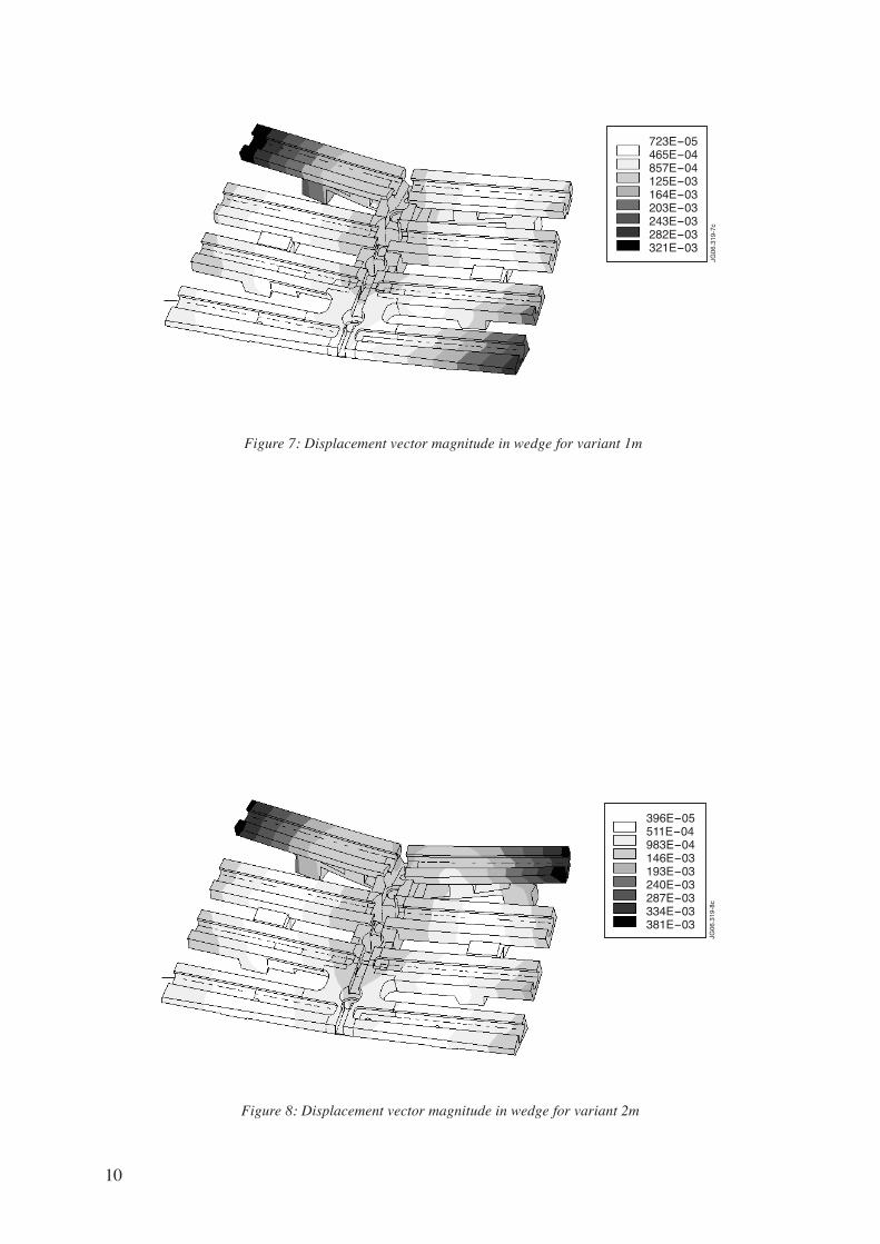
The wedge is expected to be one of the most critical structural elements along with the bolts and
pins. Figs. 7 and 8 show the distribution of the magnitude of the displacement vector in the wedge
for two variants of the loading. The displacement reaches a maximum value of 0.4 mm in the top

5
“wing”. Note that most of the wedge bending comes from the wedge-adaptor bolts preloading.
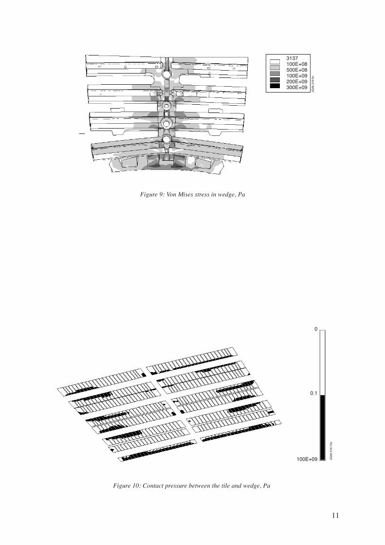
Fig. 9 shows the distribution of the equivalent von Mises stress in the wedge after applying the
bolt preloading and all EM loads for variant 2. The primary bending stress in the wedge and in the
adaptor plate is below the allowable stress for inconel (about 400 MPa).
The contact interaction between the structure elements has been analyzed in detail.
The analysis of the tiles’ stress-strain state shows that the lamellae are mostly in tight contact with
the spacers and no significant lamellae detachment occurs.
The distribution of contact pressure between the tile and wedge after the bolt pre-loading is shown
in Fig. 10. The black colour indicates regions with tight contact, and white colour - regions with
low or zero contact pressure. Pre-tension of the links between the tiles and wedge is not sufficient
to provide tight contact over the whole tile- wedge interface. Further loading apart from pre-loading
(EM loads) do not lead to any significant change of the contact pressure distribution.
After pre-loading of the bolts which connect the wedge with the adaptor and the adaptor with the
base the structure does not lose contact with the base plate. Due to the EM loads one wedge “leg”
located under the top “wing” loses the contact (see Fig. 8). Local stiffening of the wedge can
improve this situation.
It has been found that the force increase in the bolts due to the EM loading does not exceed 8%
of the bolts pre-loading. The highest stresses in the bolts are given in Table 3. These stresses are
within the allowable limits. The force taken by the shear pins at the adaptor-base interface does not
exceed 5.8 kN. This corresponds to the von Mises stress in the pin about 220 MPa, which is much
less than the allowable stress for pin material (about 500 MPa).
CONCLUSIONS
• Based on the CATIA V5 model delivered from FZJ, 3-D FE models of the main components of
the JET W-LBSRP divertor tile block were developed for the electromagnetic and structural
analysis.
• Local eddy current, transport current and halo current loads were addressed by the EM analysis
by which the nodal EM forces were obtained which occur due to the interaction of the currents
with the external fields. The integral EM forces and moments on the structure elements were
calculated.
• Structural analysis has been performed for two selected variants of the EM loading (including
bolts preloading). The contact interaction between the main parts of the divertor block and the
pre-loading of the bolts which connect the wedge, adaptor and base were taken into account.
• Bending stresses in the inconel wedge and adaptor plate are acceptable.
• Stresses in the bolts which connect the main structural components (tiles, wedge and adaptor
plate) are within the allowable limits.
• Forces on the shear pins, which connect the wedge with the adaptor and the adaptor with the
base are less than 5.8 kN with assumption of zero friction. .
6
• The tiles are sufficiently compressed by the tie rods in order to keep tight contact between the
lamellae and spacers during loading.
• Pre-tension of the links between the tiles and wedge is not sufficient to provide tight contact
over the whole tile- wedge interface.
• After pre-loading of the bolts which connect the wedge with the adaptor and the adaptor with the
base the structure does not lose contact with the base plate. Due to the EM loads one wedge
“leg” located under the top “wing” loses the contact. To provide a reliable electrical contact
from the lamellae via the wedge to the base plate for a defined path of the halo currents the
wedge can be locally stiffened.
ACKNOWLEDGEMENT
This work, supported by the European Communities under the contract of Association between
EURATOM/FZJ, was carried out within the framework of the European Fusion Development
Agreement. The views and opinions expressed herein do not necessarily reflect those of the European
Commission.
REFERENCES
[1]. J. Wesson, The science of JET, Abingdon, Oxon, OX14 3EA, UK, 2000.
[2]. O.C. Zienkiewicz, R.L. Taylor, The Finite Element Method, fifth edition, Butterworth-
Heinemann, 2000.
[3]. N.F .Berchov, V.A. Bykov, V.M. Komarov, M.D. Korolkov, I.V. Mazul, 3D stress analysis of
ITER divertor cassette under thermal and electromagnetic loads, Plasma Devices and
Operations, 1998, Vol. 6, pp. 65-72.
[4]. ANSYS. Theory reference. Rel. 11 Ed. P. Kothnke / ANSYS Inc. Huston, 2001.
[5] . S. Sadakov, Ed. Bondarchuk, N. Doinikov, et al, Detailed electromagnetic analysis for design
optimization of a tungsten divertor plate for JET, at these proceedings.
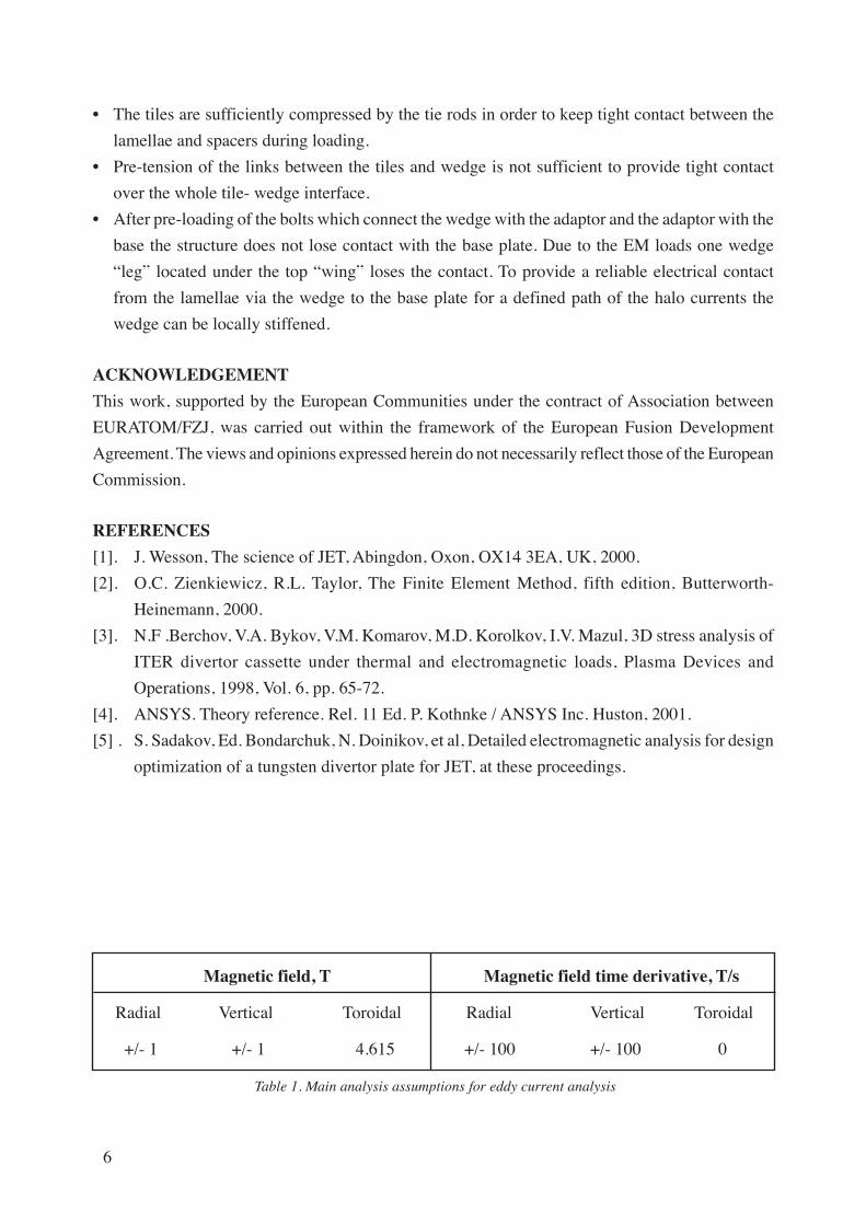
Magnetic field, T Magnetic field time derivative, T/s
Radial Vertical Toroidal Radial Vertical Toroidal
+/- 1 +/- 1 4.615 +/- 100 +/- 100 0
Table 1. Main analysis assumptions for eddy current analysis

7
Magnetic field, T Magnetic field time derivative, T/s
Radial Vertical Toroidal Halo current, kA Transport current, kA
+/- 1 +/- 1 4.615 18 9.6
Table 2. Main analysis assumptions for the halo current and transport current analyses
Location Diameter Material Tension Tensile stress Allowable stress
mm kN MPa S1= σσσσσ0.2/1.5, MPa
Wedge 8 Inconel 4.0 100 667
adaptor M8 718
Wedge 12 Inconel 4.6 51 667
adaptorM12 718
Adaptor-base 12 Inconel 5.5 61 667
M12 718
Table 3. Tension in the most loaded bolts
Tungsten LBSRP tiles
JG06
.319
-1c
Figure 1: The JET torus

8
Figure 2: LBSRP divertor tile block (CAD model, lamella design)
Figure 3: FE model of tile
JG06.319-2c
Rails Adaptor plateTile
Wedge
JG06.319-3c
JG06.319-4c
Figure 4: FE models of wedge and adaptor plate Note that different types of elements were used for analyses:SOLID97 - for EM analyses and SOLID45 - for structural analysis.
9
Figure 5: Vector plot of the eddy current density in the wedge and adapter plate
Figure 6: Vector plot of the current density for the “halo edge” case
0
JG06
.319
-5c
JG06.319-6c
10
Figure 8: Displacement vector magnitude in wedge for variant 2m
396E-05511E-04983E-04146E-03193E-03240E-03287E-03334E-03381E-03
JG06
.319
-8c
Figure 7: Displacement vector magnitude in wedge for variant 1m
723E-05465E-04857E-04125E-03164E-03203E-03243E-03282E-03321E-03
JG06
.319
-7c
11
Figure 10: Contact pressure between the tile and wedge, Pa
Figure 9: Von Mises stress in wedge, Pa
3137100E+08500E+08100E+09200E+09300E+09
JG06
.319
-9c
100E+09
0.1
0JG
06.3
19-1
0c
Related Documents