3D Active Shape Models Of Human Brain Structures: Application To Patient-Specific Mesh Generation Nishant Ravikumar 1 , Isaac Castro-Mateos 2 , Jose M. Pozo 2 , Alejandro F. Frangi 2 and Zeike A. Taylor 1 1 CISTIB, Centre for Computational Imaging and Simulation Technologies in Biomedicine, INSIGNEO, Institute for in silico medicine, Department of Mechanical Engineering, The University of Sheffield, Western Bank, Sheffield, S10 2TN, South Yorkshire, United Kingdom 2 CISTIB, Centre for Computational Imaging and Simulation Technologies in Biomedicine, INSIGNEO, Institute for in silico medicine, Department of Electronics and Electrical Engineering, The University of Sheffield, Western Bank, Sheffield, S10 2TN, South Yorkshire, United Kingdom ABSTRACT The use of biomechanics-based numerical simulations has attracted growing interest in recent years for computer-aided diagnosis and treatment planning. With this in mind, a method for automatic mesh generation of brain structures of interest, using statistical models of shape (SSM) and appearance (SAM), for personalised computational modelling is presented. SSMs are constructed as point distribution models (PDMs) while SAMs are trained using intensity profiles sampled from a training set of T1-weighted magnetic resonance images. The brain structures of interest are, the cortical surface (cerebrum, cerebellum & brainstem), lateral ventricles and falx-cerebri membrane. Two methods for establishing correspondences across the training set of shapes are investigated and compared (based on SSM quality): the Coherent Point Drift (CPD) point-set registration method and B-spline mesh-to-mesh registration method. The MNI-305 (Montreal Neurological Institute) average brain atlas is used to generate the template mesh, which is deformed and registered to each training case, to establish correspondence over the training set of shapes. 18 healthy patients’ T1-weighted MR images form the training set used to generate the SSM and SAM. Both model-training and model-fitting are performed over multiple brain structures simultaneously. Compactness and generalisation errors of the BSpline-SSM and CPD-SSM are evaluated and used to quantitatively compare the SSMs. Leave-one-out cross validation is used to evaluate SSM quality in terms of these measures. The mesh-based SSM is found to generalise better and is more compact, relative to the CPD-based SSM. Quality of the best-fit model instance from the trained SSMs, to test cases are evaluated using the Hausdorff distance (HD) and mean absolute surface distance (MASD) metrics. Keywords:Statistical Shape Models (SSMs), Statistical Appearance Models (SAMs), Coherent Point Drift (CPD) Reg- istration, BSpline Registration, Principal Component Analysis (PCA), Cortical Surface, Lateral Ventricles, Falx-Cerebri Membrane, Patient-specific Mesh Generation * * Correspondence to: Nishant Ravikumar, E-mail: mta08nr@sheffield.ac.uk, Telephone: +447944270771 Medical Imaging 2015: Computer-Aided Diagnosis, edited by Lubomir M. Hadjiiski, Georgia D. Tourassi, Proc. of SPIE Vol. 9414, 94142D · © 2015 SPIE · CCC code: 1605-7422/15/$18 · doi: 10.1117/12.2082599 Proc. of SPIE Vol. 9414 94142D-1 DownloadedFrom:http://proceedings.spiedigitallibrary.org/on03/23/2015TermsofUse:http://spiedl.org/terms

Welcome message from author
This document is posted to help you gain knowledge. Please leave a comment to let me know what you think about it! Share it to your friends and learn new things together.
Transcript
3D Active Shape Models Of Human Brain Structures: Application ToPatient-Specific Mesh Generation
Nishant Ravikumar1, Isaac Castro-Mateos2, Jose M. Pozo2, Alejandro F. Frangi2 and Zeike A. Taylor1
1CISTIB, Centre for Computational Imaging and Simulation Technologies in Biomedicine,INSIGNEO, Institute for in silico medicine, Department of Mechanical Engineering, The University
of Sheffield, Western Bank, Sheffield, S10 2TN, South Yorkshire, United Kingdom2CISTIB, Centre for Computational Imaging and Simulation Technologies in Biomedicine,
INSIGNEO, Institute for in silico medicine, Department of Electronics and Electrical Engineering,The University of Sheffield, Western Bank, Sheffield, S10 2TN, South Yorkshire, United Kingdom
ABSTRACT
The use of biomechanics-based numerical simulations has attracted growing interest in recent years for computer-aideddiagnosis and treatment planning. With this in mind, a method for automatic mesh generation of brain structures ofinterest, using statistical models of shape (SSM) and appearance (SAM), for personalised computational modelling ispresented. SSMs are constructed as point distribution models (PDMs) while SAMs are trained using intensity profilessampled from a training set of T1-weighted magnetic resonance images. The brain structures of interest are, the corticalsurface (cerebrum, cerebellum & brainstem), lateral ventricles and falx-cerebri membrane. Two methods for establishingcorrespondences across the training set of shapes are investigated and compared (based on SSM quality): the CoherentPoint Drift (CPD) point-set registration method and B-spline mesh-to-mesh registration method. The MNI-305 (MontrealNeurological Institute) average brain atlas is used to generate the template mesh, which is deformed and registered to eachtraining case, to establish correspondence over the training set of shapes. 18 healthy patients’ T1-weighted MR images formthe training set used to generate the SSM and SAM. Both model-training and model-fitting are performed over multiplebrain structures simultaneously. Compactness and generalisation errors of the BSpline-SSM and CPD-SSM are evaluatedand used to quantitatively compare the SSMs. Leave-one-out cross validation is used to evaluate SSM quality in terms ofthese measures. The mesh-based SSM is found to generalise better and is more compact, relative to the CPD-based SSM.Quality of the best-fit model instance from the trained SSMs, to test cases are evaluated using the Hausdorff distance (HD)and mean absolute surface distance (MASD) metrics.
Keywords:Statistical Shape Models (SSMs), Statistical Appearance Models (SAMs), Coherent Point Drift (CPD) Reg-istration, BSpline Registration, Principal Component Analysis (PCA), Cortical Surface, Lateral Ventricles, Falx-CerebriMembrane, Patient-specific Mesh Generation
∗
∗Correspondence to: Nishant Ravikumar, E-mail: [email protected], Telephone: +447944270771
Medical Imaging 2015: Computer-Aided Diagnosis, edited by Lubomir M. Hadjiiski, Georgia D. Tourassi, Proc. of SPIE Vol. 9414, 94142D · © 2015 SPIE · CCC code: 1605-7422/15/$18 · doi: 10.1117/12.2082599
Proc. of SPIE Vol. 9414 94142D-1
Downloaded From: http://proceedings.spiedigitallibrary.org/ on 03/23/2015 Terms of Use: http://spiedl.org/terms
1 INTRODUCTION
Statistical models of shape and appearance are important tools for medical image analysis and segmentation that havebeen employed extensively in recent years. The construction of SSMs as PDMs (i.e. using point-based representations ofshapes), and their application to automatic segmentation of tissues, organs and bones, in medical images, was first proposedby Cootes, et al. 1 A review of past approaches to training SSMs and their application to medical image segmentation, ispresented by Heimann, et al. 2 Point-based representation of shapes/surfaces are computationally less expensive than theirimplicit (signed distance functions) counterparts in relation to SSM construction and application. The first step towardsconstruction of SSMs is establishing point-wise correspondence across a training set of shapes. Previous studies have inves-tigated various methods to this end, which can be broadly classified into two categories, namely - group-wise registrationand template-to-training set registration methods. The latter class of methods is adopted here. The main contribution of thisstudy is a comparison of two non-rigid registration techniques, used to establish point-wise correspondence across a train-ing set of shapes, in terms of the quality of their respective trained SSMs. The two methods, Coherent Point Drift point-setregistration 3 and BSpline mesh-to-mesh registration, are used to deform a template mesh to each training case. These twotechniques are chosen to establish shape correspondence as they are state-of-the-art registration algorithms within theirrespective classes of point-based and mesh-based, non-rigid registration methods. Due to the large variation in shapes seenacross the training set, for the brain structures of interest, registration algorithms capable of recovering only similarity oraffine mappings between shapes are inadequate for such an application. Alternative methods for establishing correspon-dence across a population with large variation in shapes and constructing SSMs are presented in 4 , 5 , 6 , 7 , 8 , 9 . Acomparison of the two methods chosen in this study, is performed with respect to the quality of their corresponding SSMs,quantified in terms of compactness and generalisation. The primary motivation here is to develop a patient-specific meshgeneration pipeline for applications involving finite element (FE) simulations, widely used in recent years for computer-assisted diagnosis & surgeries. Segmenting structures of interest from patients’ brain MR images and creating personalisedmeshes for use in FE applications can be a time-consuming and cumbersome task. The aim of the proposed pipeline isto provide ready-to-use tetrahedral (volumetric) meshes of brain structures of interest, given a patient’s T1-weighted MRimage as input, for use in numerical simulations. The brain structures of interest here are the cortical surface, falx-cerebrimembrane and lateral ventricles. These three structures are chosen based on past evidence of their distinct mechanicalproperties, sources of inhomogeneity in the brain. Their inclusion has been shown to significantly affect the outcome FEsimulations of the brain (Ex: Modelling craniotomy-induced brain shifts 10 , 11 , 12 , 13 ). The presented framework allowsfor the easy inclusion of additional brain structures in the SSM construction and fitting pipeline. Subsequent work willlook to include the outer CSF layer (at the brain-skull interface), inner & outer skull surfaces, tentorium membrane and thefalx-cerebelli membrane.
2 ESTABLISHING CORRESPONDENCES
A major challenge with constructing 3D SSMs lies in reliably establishing correspondences across a training set of shapesand the methods employed for this purpose depend on the manner of shape representation (i.e. point-based, parameterisedor implicit). The work presented in this study adopts a point-based representation of shapes and the discussion of associatedmethods for SSM-construction and application is limited to the same. One class of methods to establish shape correspon-dence involves deforming a template mesh to register it to each training case, so that each shape is composed of the samenumber of points (i.e. one-to-one correspondence across training shapes). This is adopted here and two non-rigid regis-tration techniques are investigated, a point-based registration method and a mesh-based registration method. T1-weightedMR training images acquired from a public database † are rigidly aligned to the MNI-305 average brain atlas ‡ which servesas the template image. The MNI brain atlas is chosen to generate the template mesh in order to minimise the effect of anybias that may be introduced by choosing the template from the training set. The ventricles & falx-cerebri membrane aresegmented manually from the training set and the template image while cortical surface masks are generated automatically
†IXI database, available at: www.brain-development.org; copyright: Imperial College of Science, Technology and Medicine, 2007‡Available at: www.bic.mni.mcgill.ca; copyright: 1993 − 2009 Louis Collins, McConnell Brain Imaging Centre, Montreal Neurological Institute,
McGill University
Proc. of SPIE Vol. 9414 94142D-2
Downloaded From: http://proceedings.spiedigitallibrary.org/ on 03/23/2015 Terms of Use: http://spiedl.org/terms
I. FSL brain extraction tool
Training Set: Ti- weighted MR images
Manual I segmentation
Il. Rigid alignment
IV. Non -rigid registration
Training set of shapes /meshes
B- Spline, CPD
1X1
MNI -305 average brain atlas:Template image
Ill. Manual segmentation
Template Mesh
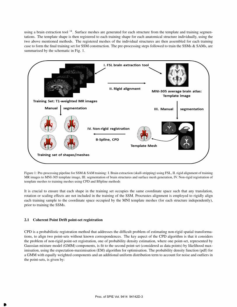
using a brain extraction tool 14. Surface meshes are generated for each structure from the template and training segmen-tations. The template shape is then registered to each training shape for each anatomical structure individually, using thetwo above mentioned methods. The registered meshes of the individual structures are then assembled for each trainingcase to form the final training set for SSM construction. The pre-processing steps followed to train the SSMs & SAMs, aresummarised by the schematic in Fig. 1.
Figure 1: Pre-processing pipeline for SSM & SAM training: I. Brain extraction (skull-stripping) using FSL, II. rigid alignment of trainingMR images to MNI-305 template image, III. segmentation of brain structures and surface mesh generation, IV. Non-rigid registration oftemplate meshes to training meshes using CPD and BSpline methods
It is crucial to ensure that each shape in the training set occupies the same coordinate space such that any translation,rotation or scaling effects are not included in the training of the SSM. Procrustes alignment is employed to rigidly aligneach training sample to the coordinate space occupied by the MNI template meshes (for each structure independently),prior to training the SSMs.
2.1 Coherent Point Drift point-set registration
CPD is a probabilistic registration method that addresses the difficult problem of estimating non-rigid spatial transforma-tions, to align two point-sets without known correspondences. The key aspect of the CPD algorithm is that it considersthe problem of non-rigid point-set registration, one of probability density estimation, where one point-set, represented byGaussian mixture model (GMM) components, is fit to the second point-set (considered as data points) by likelihood max-imisation, using the expectation-maximisation (EM) algorithm for optimisation. The probability density function (pdf) fora GMM with equally weighted components and an additional uniform distribution term to account for noise and outliers inthe point-sets, is given by:
Proc. of SPIE Vol. 9414 94142D-3
Downloaded From: http://proceedings.spiedigitallibrary.org/ on 03/23/2015 Terms of Use: http://spiedl.org/terms
p(x) =w
N+ (1− w)
M∑m=1
p(x|m)
M, 0 ≤ w ≤ 1; (1a)
p(x|m) =1
(2πσ2)D/2exp−
12||x−T∗(ym,θ)||2
σ2 (1b)
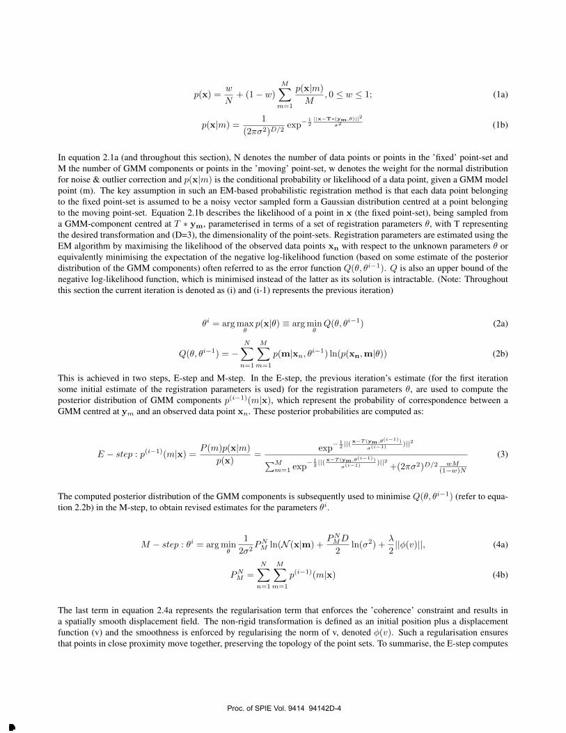
In equation 2.1a (and throughout this section), N denotes the number of data points or points in the ’fixed’ point-set andM the number of GMM components or points in the ’moving’ point-set, w denotes the weight for the normal distributionfor noise & outlier correction and p(x|m) is the conditional probability or likelihood of a data point, given a GMM modelpoint (m). The key assumption in such an EM-based probabilistic registration method is that each data point belongingto the fixed point-set is assumed to be a noisy vector sampled form a Gaussian distribution centred at a point belongingto the moving point-set. Equation 2.1b describes the likelihood of a point in x (the fixed point-set), being sampled froma GMM-component centred at T ∗ ym, parameterised in terms of a set of registration parameters θ, with T representingthe desired transformation and (D=3), the dimensionality of the point-sets. Registration parameters are estimated using theEM algorithm by maximising the likelihood of the observed data points xn with respect to the unknown parameters θ orequivalently minimising the expectation of the negative log-likelihood function (based on some estimate of the posteriordistribution of the GMM components) often referred to as the error function Q(θ, θi−1). Q is also an upper bound of thenegative log-likelihood function, which is minimised instead of the latter as its solution is intractable. (Note: Throughoutthis section the current iteration is denoted as (i) and (i-1) represents the previous iteration)
θi = argmaxθp(x|θ) ≡ argmin
θQ(θ, θi−1) (2a)
Q(θ, θi−1) = −N∑n=1
M∑m=1
p(m|xn, θi−1) ln(p(xn,m|θ)) (2b)
This is achieved in two steps, E-step and M-step. In the E-step, the previous iteration’s estimate (for the first iterationsome initial estimate of the registration parameters is used) for the registration parameters θ, are used to compute theposterior distribution of GMM components p(i−1)(m|x), which represent the probability of correspondence between aGMM centred at ym and an observed data point xn. These posterior probabilities are computed as:
E − step : p(i−1)(m|x) = P (m)p(x|m)
p(x)=
exp− 1
2 ||(x−T (ym,θ(i−1))
σ(i−1))||2∑M
m=1 exp− 1
2 ||(x−T (ym,θ(i−1))
σ(i−1))||2
+(2πσ2)D/2 wM(1−w)N
(3)
The computed posterior distribution of the GMM components is subsequently used to minimise Q(θ, θi−1) (refer to equa-tion 2.2b) in the M-step, to obtain revised estimates for the parameters θi.
M − step : θi = argminθ
1
2σ2PNM ln(N (x|m) +
PNMD
2ln(σ2) +
λ
2||φ(v)||, (4a)
PNM =
N∑n=1
M∑m=1
p(i−1)(m|x) (4b)
The last term in equation 2.4a represents the regularisation term that enforces the ’coherence’ constraint and results ina spatially smooth displacement field. The non-rigid transformation is defined as an initial position plus a displacementfunction (v) and the smoothness is enforced by regularising the norm of v, denoted φ(v). Such a regularisation ensuresthat points in close proximity move together, preserving the topology of the point sets. To summarise, the E-step computes
Proc. of SPIE Vol. 9414 94142D-4
Downloaded From: http://proceedings.spiedigitallibrary.org/ on 03/23/2015 Terms of Use: http://spiedl.org/terms

the posterior probabilities of the GMM components using Bayes’ theorem, the M-step updates estimates of the registrationparameters, based on the computed virtual correspondences. The algorithm iteratively alternates between these two stepsuntil a convergence criterion is reached.
2.2 BSpline mesh registration
B-splines are a common method to represent continuous and smooth transformations, with a limited number of degrees offreedom. In particular, cubic B-splines are the basis for Free Form Deformation (FFD) based non-rigid registration 15. Fora 3-dimensional object, as in this study, a regular grid of control points define the B-spline domain. The distances betweenconsecutive control points determine the scale at which the deformation is described. This is related with the number ofcontrol points, which determines the degrees of freedom or number of parameters for the transformation.
B-splines comprise scalar basis functions, centred at the control point, with finite support. The degree of B-splines aredetermined by the degree of the corresponding polynomial that generates it. Cubic B-splines are defined by piece-wisecubic polynomials, satisfying continuity and a continuous derivative up to second order. In 3 dimensions, the basis functionat each control point is formed by the tensor product of the 1-dimensional B-splines, inheriting the desirable continuity andfinite-support properties. These properties make this basis a very convenient parametrisation for smooth transformations:
T (x) = x+∑I
dIB(x− xI),
where I is the set of all control points, xI denotes the position of a control point in I , and dI is the vectorial parameter ofI , usually described as the control point displacement and B denotes the corresponding basis function.
Cubic B-splines have been extensively used for image registration. However, they are also applicable for mesh morphing.We first obtain a bounding box aligned with the three principal axes of the considered mesh, which determines the extentand orientation of the grid of control points.
An additional regularisation term is included as an internal energy of the triangular mesh, based on elastic energies relativeto the triangle edge lengths, considered as continuous material with homogenous Young’s modulus. This regularisationhelps preserve the size and topology of the template mesh triangles as much as possible.
The similarity energy is composed of two symmetric terms measuring the distances from the patient-specific surface ge-ometry and the corresponding surface on the morphed template model. Since no point correspondence exist a priori,point-to-point distances cannot be used. At each iteration, for each point of the template mesh, its distance to the targetsurface is computed. Similarly, for each point of the target mesh, its distance to the template surface is also computed. Thesimilarity energy is then defined by the summation of the square of all these distances. The symmetric consideration of thedistances in both directions, allows the morphing of the template to wrinkled surfaces, as the ones appearing in the cortex.
The optimisation algorithm is gradient-descent with direct line-search. This algorithm is easy to implement and all thederivatives involved from both the similarity energy and the internal energy, can be analytically computed.
3 SSM CONSTRUCTION
SSMs are trained by estimating the mean and the principal modes of variation, of the positions of established correspon-dence points across the training set of shapes. This is achieved by first establishing point-wise correspondence across thetraining set of shapes via point-set or surface registration and subsequently analysing the statistics of the coordinates ofeach correspondence point across the training set, typically done via principal component analysis (PCA) of the training setof registered shapes. PCA is a widely used technique of dimensionality reduction that allows the observed variation across
Proc. of SPIE Vol. 9414 94142D-5
Downloaded From: http://proceedings.spiedigitallibrary.org/ on 03/23/2015 Terms of Use: http://spiedl.org/terms

a training data set to be expressed using just a few principal modes of variation (i.e. eigenvectors) and can be defined asthe linear projection of data on to a lower dimensional, ’principal subspace’ such that the variance of the projected data ismaximised 16. Following registration of the training set of shapes, one-to-one correspondence is established across the setwhich allows each training shape to be projected as a data point in a 3n-dimensional space (2n-dimensional for 2D shapes).PCA is based on the assumption that the observed shapes/data points are drawn from a Gaussian distribution and lie withinan ellipsoid (or hyper-ellipsoid) whose major axes represent the orthonormal set of eigenvectors (of the covariance matrixof the training set of shapes). Each eigenvector represents a principal mode of variation in shape across the training setwhich equates to a description of the collective variation of correspondence points across the training set of shapes. SSMscan be used to reconstruct any shape from the training set and to create new shapes, constrained by the observed varia-tions from the training set. I.e. any model instance can be expressed as a linear combination of the mean shape and theeigenvectors & eigenvalues of the covariance matrix of the training data set.
Each shape is represented as a shape vector given by C = [px1, py1, pz1, ....pxn, pyn, pzn] by concatenation of the coordi-nates of each correspondence point, located on the surface of each training shape. These shape vectors are organised into ashape matrix of size (3nxN), where (n) represents the number of correspondence points and (N) represents the number oftraining shapes. The idea is to be able to represent any new shape s, drawn from the distribution of these shape vectors inthe 3n-dimensional space using a linear combination of the first P-modes of variation, as follows:
s = s+
P∑p−1
φpβp (5)
where, s represents the mean shape and φ represents the eigenvector matrix where the columns represent the orthonormalset of eigenvectors/principal modes of variation. The β vector represents the shape weights/model parameters which canbe varied to generate new shape instances constrained by the observed variations in shape in the training set. β is typicallyconstrained to lie within the limits,−3
√λp ≤ βp ≤ +3
√λp, where λp corresponds to the pth eigenvalue of the covariance
matrix (S) of the training set. PCA involves estimating S of the training set (computed using the deviation of each trainingsample from the sample mean), followed by an Eigen-decomposition or singular value decomposition (SVD) of S. SVDis favoured as it offers better numerical stability in comparison to Eigen-decompostion, especially in the case of an ill-conditioned covariance matrix. Following PCA of the covariance matrix of the training set of shapes, the principal modesof variation in shape across the training set are obtained in the form of eigenvectors and their corresponding eigenvalues.The magnitude of each eigenvalue represents the total variation captured by its corresponding principal mode of variationin shape. Traditionally when constructing a SSM the number of modes (P) required to describe 96% - 98% of the totalvariation in the training set, are retained while the remainder are considered to capture noise and ignored. The first modeof variation and the mean shapes of the BSpline-SSM and CPD-SSM, for all three brain structures of interest are shown inFig.2 & 3 below. §
§Animations depicting the first three modes of shape variation in brain structures can be visualised at: http://www.cistib.org/∼nravikumar/
Proc. of SPIE Vol. 9414 94142D-6
Downloaded From: http://proceedings.spiedigitallibrary.org/ on 03/23/2015 Terms of Use: http://spiedl.org/terms
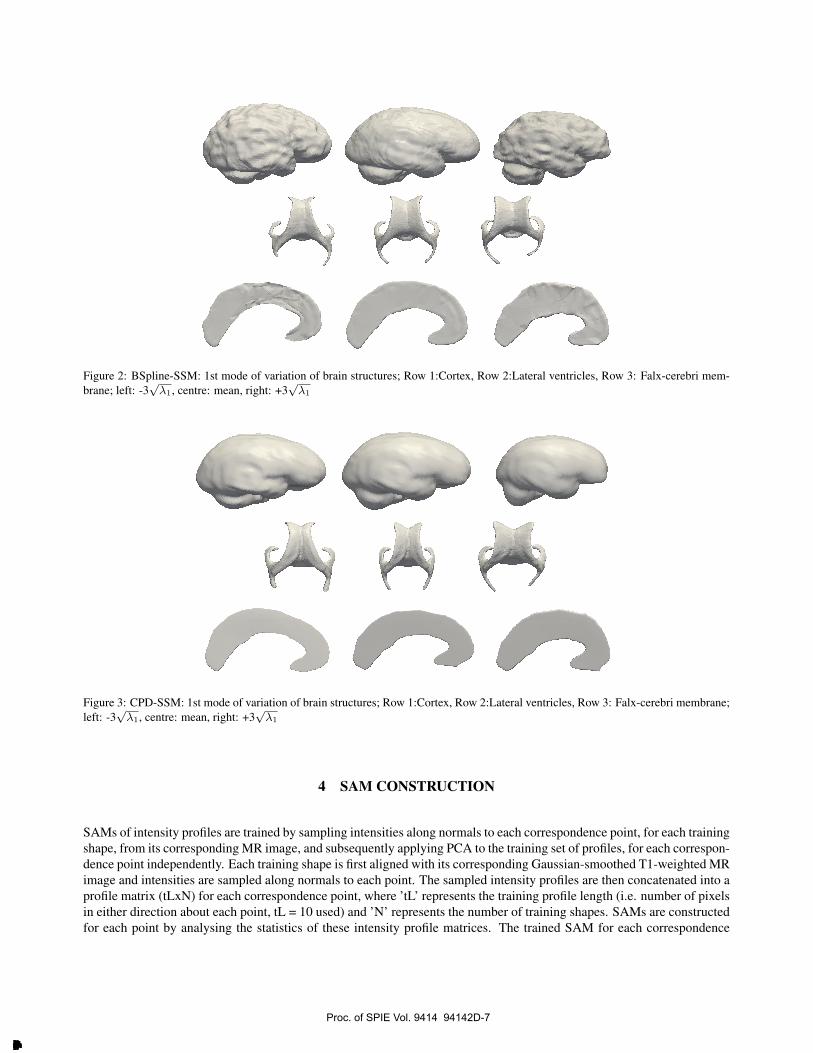
Figure 2: BSpline-SSM: 1st mode of variation of brain structures; Row 1:Cortex, Row 2:Lateral ventricles, Row 3: Falx-cerebri mem-brane; left: -3
√λ1, centre: mean, right: +3
√λ1
Figure 3: CPD-SSM: 1st mode of variation of brain structures; Row 1:Cortex, Row 2:Lateral ventricles, Row 3: Falx-cerebri membrane;left: -3
√λ1, centre: mean, right: +3
√λ1
4 SAM CONSTRUCTION
SAMs of intensity profiles are trained by sampling intensities along normals to each correspondence point, for each trainingshape, from its corresponding MR image, and subsequently applying PCA to the training set of profiles, for each correspon-dence point independently. Each training shape is first aligned with its corresponding Gaussian-smoothed T1-weighted MRimage and intensities are sampled along normals to each point. The sampled intensity profiles are then concatenated into aprofile matrix (tLxN) for each correspondence point, where ’tL’ represents the training profile length (i.e. number of pixelsin either direction about each point, tL = 10 used) and ’N’ represents the number of training shapes. SAMs are constructedfor each point by analysing the statistics of these intensity profile matrices. The trained SAM for each correspondence
Proc. of SPIE Vol. 9414 94142D-7
Downloaded From: http://proceedings.spiedigitallibrary.org/ on 03/23/2015 Terms of Use: http://spiedl.org/terms
point aids in point-wise fitting of the trained SSM to new MR images (I.e. test cases not included in the SSM & SAMtraining). Images with better contrast along the boundaries of structures/objects (lateral ventricles, for example), relativeto the original T1-weighted MR image, can help improve the quality of ASM-fitting. To this end, feature images (F) oftenreferred to as ’edge-indicator’ images are also used to construct SAMs, independent of their MR image (M) counterparts.These feature images (for each training case) are computed as follows:
F = 1/(1 + || 5 I||2) (6)
SAMs trained from both types of images are used simultaneously in the ASM-fitting process, by computing the optimalmovement for each correspondence point using a weighted combination of their respective Mahalanobis distances. Fitsachieved using combined information from both types of images is compared with those obtained using just MRI-basedSAMs, presented in the results section.
5 ASM-FITTING
The term ASM typically refers to a method that uses SAMs of intensity profiles to compute the desired movement of pointsalong normals, to best match the sampled test profiles in the image and segment structures of interest. The trained SSMregularises the desired displacements and computes the model-predicted shape. Traditionally fitting of ASMs to imageswas achieved by minimising the Mahalanobis distance metric in real space, using the derivates of sampled intensity profiles(i.e. edges) and the inverse of the covariance matrix (S−1). However, this method has been shown to be sensitive to noiseand the presence of weak edges in the image, which adversely affects the quality of the fits achieved. To address thisproblem here the Mahalanobis distance between the sampled intensity profiles (for each correspondence point) and thecorresponding trained mean profiles is minimised, in the appearance model-space rather than real space. This providesmore robust ASM-fits to MR images, relative to the former method. As stated previously, an appearance model is trainedfor each correspondence point, across the set of training shape & MR image pairs. The first step towards fitting the trainedSSM to a new image, is to rigidly align the mean shape of the SSM with the new image, which is taken to be the first modelinstance in the iterative ASM-fitting process. Following this rigid alignment, ’fitting’ intensity profiles are sampled alongnormals to points lying on the mean surface, from the new image. The length of the fitting profiles (fL = 2∗ tL) are takento be twice that of the training profiles, used for training the SAMs. The cost function minimised to estimate the optimalposition for each correspondence point in the ASM-fitting process is given by:
E = argminα
fL∑i=1
[ωα2Mi
λi+ (1− ω)
α2Fi
λi] (7)
In equation 5.1 αi represents the ith component of the appearance weights vector (based on the trained SAM for eachcorrespondence point), i.e. the projection of the ’fitting’ profile to the trained SAM-space, for each point. Here ω representsthe weight/influence of the SAM trained using feature images, relative to its MRI-based counterpart, in relation to thedesired movement computed for each model point. The quantity being minimised equates to the Mahalanobis distancein SAM-space, of the ’fitting’ profiles from the means of the corresponding trained SAMs. The optimal position for eachpoint, is computed along its normal, independently at each iteration of the algorithm to create a new ’desired’ shape (snew).This new shape is projected to the trained SSM-space to obtain the ’best-fit’ shape (sfit) as follows:
β = φT (snew − s) (8a)
Proc. of SPIE Vol. 9414 94142D-8
Downloaded From: http://proceedings.spiedigitallibrary.org/ on 03/23/2015 Terms of Use: http://spiedl.org/terms

sfit = s+
P∑p−1
φpβp (8b)
Here s represents the mean shape and φT represents the transpose of the eigenvector matrix, i.e. the principal modes ofvariation in shape and β, limited to ±3σ, is referred to as the shape weights or shape model parameters vector. Bothmodel-training and model-fitting are performed simultaneously for all three brain structures. This prevents the meshesfrom intersecting, following the model-fitting step to generate patient-specific meshes.
ASM-Fitting algorithm
for i = 1:number of iterations (convergence criterion)
• Current model instance (mean shape from SSM used as initial instance) rigidly aligned to test image
• Intensity profiles sampled normal to (n) points in either direction over test image
• αMi&αFi appearance weights vectors computed for each model point
for j = 1:N (number of model points)
• Compute αMi&αFi vectors
• Compute Mahalanobis distances in SAM-space as; M2M=
∑fLi=1 α
2Mi/λi& M2
F=∑fLi=1 α
2Fi/λi
• Compute movement term as a weighted combination of M2M & M2
F
end
• Compute optimal displacements for N model points by minimising cost function E (refer to equation 5.1)
• Compute β shape weights vector
• Best fit model instance computed as: sfit = s+∑Pp−1 φpβp
• Computed best-fit shape sfit used as current model instance for the subsequent iteration
end
Proc. of SPIE Vol. 9414 94142D-9
Downloaded From: http://proceedings.spiedigitallibrary.org/ on 03/23/2015 Terms of Use: http://spiedl.org/terms

6 COMPARISON OF STATISTICAL SHAPE MODELS
The quality of the trained BSpline-SSM and CPD-SSM are quantitatively compared using cross-validation experiments,based on measures of generalisation and compactness of the SSMs. The generalisation capability of a trained SSM isa measure of its ability to reconstruct unseen shapes, while the compactness of the model can be described in terms ofthe number of modes of variation necessary to reconstruct a test shape to an adequate degree of accuracy. Compactnessstudies are conducted prior to the former, to identify the optimal number of modes of variation for each type of SSM. Theidentified number of modes are subsequently used for the generalisation study. The surface reconstruction error to evaluatecompactness and generalisation of the SSMs is quantified using two measures, the Hausdorff distance (HD) and meanabsolute surface distance (MASD), formulated as follows:
HD = max(max(dmin(A,B)),max(dmin(B,A))) (9)
MASD = mean(mean(dmin(A,B)),mean(dmin(B,A))) (10)
In the equations above, vector dmin(A,B) denotes the minimum distance for each point in surface A to surface B. Allsurface reconstruction errors are computed with respect to the ground truth meshes used to generate the training sets.
6.1 Compactness
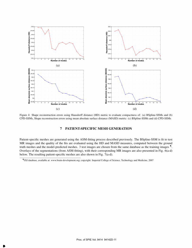
The compactness of the SSMs trained using BSpline and CPD registration methods are compared by plotting the meanshape reconstruction errors against the corresponding number of modes of variation used to compute the SSM-predictedshape. A SSM is considered to be more compact if it captures a higher degree of variation in shape, over fewer eigen-modes of variation. 10 test shapes are selected at random from the training set and projected to the trained SSM space(trained using the remaining training samples). Subsequently surface reconstruction errors are computed, based on themodel-predicted shape for each SSM. Plots depicting the mean surface reconstruction errors (over 5 test cases) against thecorresponding number of modes of variation, are presented in Fig. 4(a-d) below.
The HD and MASD error plots for the two SSMs indicate that the BSpline-SSM is more compact, relative to its CPDcounterpart. This is inferred as the computed HD and MASD magnitude is lower for the former, for any number of modesused. The lowest reconstruction errors are obtained when 14 modes are used and subsequently, 14 modes of variation areused in the generalisation study.
6.2 Generalisation Errors
Leave-one-out cross validation experiments are performed by training both BSpline-SSMs and CPD-SSMs and fitting themto the test sample excluded from the training set. This is done in an exhaustive manner such that a total of 18 SSMs areconstructed for each registration method, leaving one training sample out in each case. Subsequently the left out test shapeis then projected to the principal space of its corresponding SSM (for both BSpline & CPD models), to reconstruct themodel-predicted shape as per equations 5.2a&b. The accuracy of the shape reconstructions are compared against theirrespective ground truth shapes, using the HD & MASD metrics. The results are described by the bar plots in Fig. 5(a-b)below.
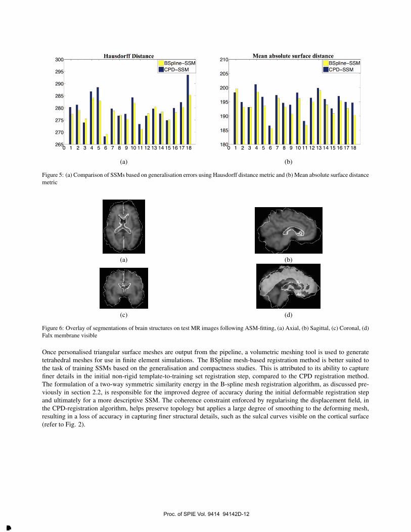
The generalisation errors are found to be lower in magnitude for the BSpline-SSM in comparison to the CPD-SSM. Thisis verified by the bar plots depicting the HD and MASD values for each test case, from the cross-validation experiments.The mean errors calculated over all reconstructions are, BSpline-SSM: HD = 278±4.18, MASD = 193±3.85, CPD-SSM:HD = 280± 5.94, MASD = 196± 3.60.
Proc. of SPIE Vol. 9414 94142D-10
Downloaded From: http://proceedings.spiedigitallibrary.org/ on 03/23/2015 Terms of Use: http://spiedl.org/terms
0 1 2 3 4 5 6 7 8 9 10 11 12 13 14278.1
278.15
278.2
278.25
278.3
278.35
278.4
278.45
278.5
Number of modes
Hau
sd
orf
f d
ista
nce (
HD
)
(a)
0 1 2 3 4 5 6 7 8 9 10 11 12 13 14279.6
279.7
279.8
279.9
280
280.1
280.2
280.3
Number of modes
Hau
sd
orf
f d
ista
nce (
HD
)
(b)
0 1 2 3 4 5 6 7 8 9 10 11 12 13 14193.95
194
194.05
194.1
194.15
194.2
194.25
194.3
194.35
194.4
Number of modes
Mean
ab
so
lute
su
rface d
ista
nce
(M
AS
D)
(c)
0 1 2 3 4 5 6 7 8 9 10 11 12 13 14196.05
196.1
196.15
196.2
196.25
196.3
196.35
196.4
Number of modesM
ean
ab
so
lute
su
rface d
ista
nce
(M
AS
D)
(d)
Figure 4: Shape reconstruction errors using Hausdorff distance (HD) metric to evaluate compactness of: (a) BSpline-SSMs and (b)CPD-SSMs, Shape reconstruction errors using mean absolute surface distance (MASD) metric: (c) BSpline-SSMs and (d) CPD-SSMs
7 PATIENT-SPECIFIC MESH GENERATION
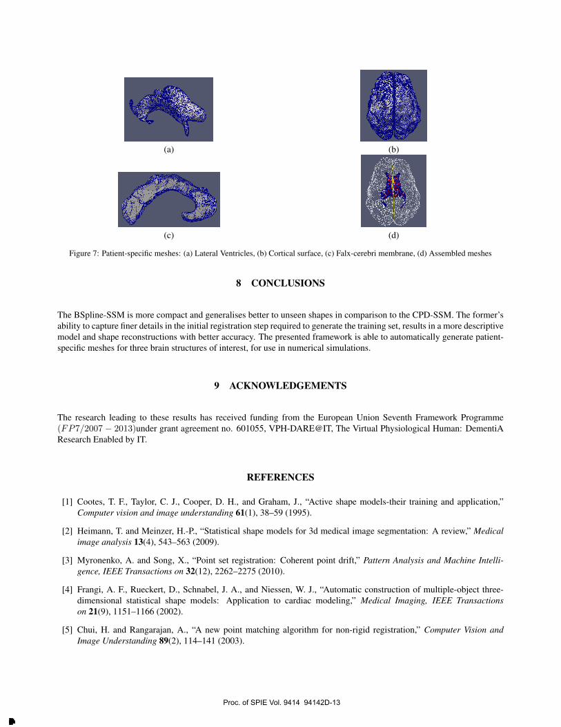
Patient-specific meshes are generated using the ASM-fitting process described previously. The BSpline-SSM is fit to testMR images and the quality of the fits are evaluated using the HD and MASD measures, computed between the groundtruth meshes and the model-predicted meshes. 3 test images are chosen from the same database as the training images ¶.Overlays of the segmentations (from ASM-fitting), with their corresponding MR images are also presented in Fig. 6(a-d)below. The resulting patient-specific meshes are also shown in Fig. 7(a-d).
¶IXI database, available at: www.brain-development.org; copyright: Imperial College of Science, Technology and Medicine, 2007
Proc. of SPIE Vol. 9414 94142D-11
Downloaded From: http://proceedings.spiedigitallibrary.org/ on 03/23/2015 Terms of Use: http://spiedl.org/terms
300Hausdorff Distance
295 -
290 -
285 -
280
E
5-
0
501 2 3 4
c
BSpline-SSMMCPD-SSM
I I F i r r F I5 6 7 8 9 10 11 12 13 14 15 16 17 18
210Mean absolute surface distance
205-
200-
195-
190-
185-
1800 1
BSpline-SSMMCPD-SSM
11111[1 ill1 2 3 4 5 6 7 8 9 10 11 12 13 14 15 16 17 18
(a) (b)
Figure 5: (a) Comparison of SSMs based on generalisation errors using Hausdorff distance metric and (b) Mean absolute surface distancemetric
(a) (b)
(c) (d)
Figure 6: Overlay of segmentations of brain structures on test MR images following ASM-fitting, (a) Axial, (b) Sagittal, (c) Coronal, (d)Falx membrane visible
Once personalised triangular surface meshes are output from the pipeline, a volumetric meshing tool is used to generatetetrahedral meshes for use in finite element simulations. The BSpline mesh-based registration method is better suited tothe task of training SSMs based on the generalisation and compactness studies. This is attributed to its ability to capturefiner details in the initial non-rigid template-to-training set registration step, compared to the CPD registration method.The formulation of a two-way symmetric similarity energy in the B-spline mesh registration algorithm, as discussed pre-viously in section 2.2, is responsible for the improved degree of accuracy during the initial deformable registration stepand ultimately for a more descriptive SSM. The coherence constraint enforced by regularising the displacement field, inthe CPD-registration algorithm, helps preserve topology but applies a large degree of smoothing to the deforming mesh,resulting in a loss of accuracy in capturing finer structural details, such as the sulcal curves visible on the cortical surface(refer to Fig. 2).
Proc. of SPIE Vol. 9414 94142D-12
Downloaded From: http://proceedings.spiedigitallibrary.org/ on 03/23/2015 Terms of Use: http://spiedl.org/terms
(a) (b)
(c) (d)
Figure 7: Patient-specific meshes: (a) Lateral Ventricles, (b) Cortical surface, (c) Falx-cerebri membrane, (d) Assembled meshes
8 CONCLUSIONS
The BSpline-SSM is more compact and generalises better to unseen shapes in comparison to the CPD-SSM. The former’sability to capture finer details in the initial registration step required to generate the training set, results in a more descriptivemodel and shape reconstructions with better accuracy. The presented framework is able to automatically generate patient-specific meshes for three brain structures of interest, for use in numerical simulations.
9 ACKNOWLEDGEMENTS
The research leading to these results has received funding from the European Union Seventh Framework Programme(FP7/2007 − 2013)under grant agreement no. 601055, VPH-DARE@IT, The Virtual Physiological Human: DementiAResearch Enabled by IT.
REFERENCES
[1] Cootes, T. F., Taylor, C. J., Cooper, D. H., and Graham, J., “Active shape models-their training and application,”Computer vision and image understanding 61(1), 38–59 (1995).
[2] Heimann, T. and Meinzer, H.-P., “Statistical shape models for 3d medical image segmentation: A review,” Medicalimage analysis 13(4), 543–563 (2009).
[3] Myronenko, A. and Song, X., “Point set registration: Coherent point drift,” Pattern Analysis and Machine Intelli-gence, IEEE Transactions on 32(12), 2262–2275 (2010).
[4] Frangi, A. F., Rueckert, D., Schnabel, J. A., and Niessen, W. J., “Automatic construction of multiple-object three-dimensional statistical shape models: Application to cardiac modeling,” Medical Imaging, IEEE Transactionson 21(9), 1151–1166 (2002).
[5] Chui, H. and Rangarajan, A., “A new point matching algorithm for non-rigid registration,” Computer Vision andImage Understanding 89(2), 114–141 (2003).
Proc. of SPIE Vol. 9414 94142D-13
Downloaded From: http://proceedings.spiedigitallibrary.org/ on 03/23/2015 Terms of Use: http://spiedl.org/terms

[6] Heitz, G., Rohlfing, T., and Maurer Jr, C. R., “Statistical shape model generation using nonrigid deformation of atemplate mesh,” in [Medical Imaging], 1411–1421, International Society for Optics and Photonics (2005).
[7] Davies, R. H., Twining, C. J., Cootes, T. F., Waterton, J. C., and Taylor, C. J., “3d statistical shape models using directoptimisation of description length,” in [Computer Vision?ECCV 2002 ], 3–20, Springer (2002).
[8] Cates, J., Fletcher, P. T., Styner, M., Shenton, M., and Whitaker, R., “Shape modeling and analysis with entropy-basedparticle systems,” in [Information Processing in Medical Imaging], 333–345, Springer (2007).
[9] Gooya, A., Davatzikos, C., and Frangi, A. F., “A bayesian approach to sparse model selection in statistical shapemodels,” in [SIAM Journal on Imaging Sciences ], In Press (2015).
[10] Miga, M. I., Paulsen, K. D., Kennedy, F. E., Hartov, A., and Roberts, D. W., “Model-updated image-guided neu-rosurgery using the finite element method: Incorporation of the falx cerebri,” in [Medical Image Computing andComputer-Assisted Intervention–MICCAI’99 ], 900–909, Springer (1999).
[11] Hu, J., Jin, X., Lee, J. B., Zhang, L., Chaudhary, V., Guthikonda, M., Yang, K. H., and King, A. I., “Intraop-erative brain shift prediction using a 3d inhomogeneous patient-specific finite element model,” Journal of neuro-surgery 106(1), 164–169 (2007).
[12] Wittek, A., Kikinis, R., Warfield, S. K., and Miller, K., “Brain shift computation using a fully nonlinear biomechan-ical model,” in [Medical Image Computing and Computer-Assisted Intervention–MICCAI 2005 ], 583–590, Springer(2005).
[13] Warfield, S. K., Ferrant, M., Gallez, X., Nabavi, A., Jolesz, F. A., and Kikinis, R., “Real-time biomechanical simula-tion of volumetric brain deformation for image guided neurosurgery,” in [Supercomputing, ACM/IEEE 2000 Confer-ence ], 23–23, IEEE (2000).
[14] Smith, S. M., “Fast robust automated brain extraction,” Human brain mapping 17(3), 143–155 (2002).
[15] Crum, W., Hartkens, T., and Hill, D., “Non-rigid image registration: theory and practice,” BR J RADIOL 77(007-1285(Print)), S140–S153 (2004).
[16] Bishop, C. M. et al., [Pattern recognition and machine learning ], vol. 1, springer New York (2006).
Proc. of SPIE Vol. 9414 94142D-14
Downloaded From: http://proceedings.spiedigitallibrary.org/ on 03/23/2015 Terms of Use: http://spiedl.org/terms
Related Documents