m l AIAA 2001-0311 Flying Wings / Flying Fuselages Richard M. Wood and Steven X. NASA Langley Research Center Hampton, Virginia S. Bauer 39th AIAA Aerospace Sciences Meeting & Exhibit 8-11 January 2001 / Reno, NV For permission to copy or republish, contact the American Institute of Aeronautics and Astronautics 1801 Alexander Bell Drive, Suite 500, Reston, VA 20191-4344 https://ntrs.nasa.gov/search.jsp?R=20010013825 2018-04-10T14:22:32+00:00Z

Welcome message from author
This document is posted to help you gain knowledge. Please leave a comment to let me know what you think about it! Share it to your friends and learn new things together.
Transcript

m l
AIAA 2001-0311
Flying Wings / Flying Fuselages
Richard M. Wood and Steven X.
NASA Langley Research Center
Hampton, Virginia
S. Bauer
39th AIAA Aerospace SciencesMeeting & Exhibit
8-11 January 2001 / Reno, NV
For permission to copy or republish, contact the American Institute of Aeronautics and Astronautics1801 Alexander Bell Drive, Suite 500, Reston, VA 20191-4344
https://ntrs.nasa.gov/search.jsp?R=20010013825 2018-04-10T14:22:32+00:00Z


AIAA 2001-0311
Flying Wings / Flying Fuselages
Richard M. W_x)d and Steven X. S. Bauer:
ABSTRACT
The present paper has documented the historical
relationships between various classes of all lifting
vehicles, which includes the flying wing, all wing,
tailless, lifting body, and lifting fuselage. The
diversity in vehicle focus was to ensure that all
vehicle types that ma) have contributed to or been
influenced by the development of the classical fl)ing
wing concept was investigated.
"['he paper has provided context and perspective for
present and future aircraft design studies that may
emplo_ the all lifting vehicle concept. The paper also
demonstrated the benefit of developing an
understanding of the past in order to obtain the
required knowledge to create future concepts with
significantl2_ improved aerodynamic performance.
INTRODUCTION
Even after more than a century of research and
development the flying wing is still viewed as a
unique and unconventional aircraft concept _4v. This
realit3 is even more surprising when you consider the
significant aerodynamic and structural benefits
afforded rising wing designs, compared to
conventional designs. Historical revie_vs 5__'_5"_7 on
this topic appear to point to a variety of reasons for
the slow acceptance of flying wing type vehicles.
From a technical point of view, the dominant issue
has been stability and control, which to this day
continues to plague this class of vehicle. As a result,
flying wing aircraft continue to be limited to missions
comprised of only low lift (cruise) conditions. In
addition to the technical issues, there were cultural
issues faced by this class of aircraft that consisted of
negative public perceptions and politics. In the first
half of the 2() _h century, which was the most prolific
period of flying wing development, these two issues
severely restricted technical discussions and as a
result the opportunity to mature this concept was lost.
The present cultural environment is slightl)improved
but the public perception and politics continue to
haunt this concept today
A review of the most recent aircraft design studies
shows a significant number of flying wing concepts
are under consideration, especiall_ for militar 5
applications. It is clear that the realization of the
flying wing concept is benefiting from recent
technological advances in aerodynamics, floxs
control, flight control s3stems, materials, structures,
and propulsions s_stems. It also appears that the
cultural barriers of the past are also deteriorating
allowing for the rich body of flying wing research tobe shared and studied and thus, contribute to future
vehicle development activities.
However, a review of the ongoing research indicates
that we continue to re-create the past instead of
learning from the past to create the future _5_. These
sentiments are clearl 3 stated through the ff)llowing
quotes from A. R. Weyl, 1944. -_-_-"-_
"...Flying Wing, in which at the present period more
interest than ever is being displayed."
"...it seems a fact that experience collected in the past
with tailless aeroplanes is either unknown or
forgotten or. at the least ill-judged..."
"...it is by no means sufficient that a crazy design
flies: it must fly far better than eveo'thing else in
order to raise attention attlong those closed
circles..."
The relevance of these three statements after nearly
six decades its quite remarkable. The_ point to the
need for a thorough understanding of the design
trends, historical contributions, and technical
relationships for fl3ing wing vehicles as well as other
closely related vehicle types before significant work
is performed. With this understanding will come new
Senior Research Aerodynamicist, Configuration
Aerod?namics Branch NASA Langley Research
Center, Associate Fellow AIAA
Copyright ,_, 2001 by the American Institute of
Aeronautics and Astronautics. Inc. No copyright isasserted in the United States under Title 17, U. S. Code.
The U. S. Government has a royalty-free license to
exercise all rights under the copyright claimed herein for
government purposes. All other fights are reserved b?
the copyright owner.
American Institute of Aeronauhcs and Astronautics

AIAA 2001-03 i I
design knowledge and thus, new opportunities to
create new concepts that approach the optimum
performance boundaries of powered flight. Failure todevelop this understanding will ensure that we will
once again re-create past accomplishments.
In support of this issue the present paper is focused
on documenting the historical relationships betweenvarious classes of all lifting vehicles that includes the
flying wing. The diversity in vehicle focus is toensure that all vehicle types that may have
contributed to or been influenced by the development
of the flying wing concept are investigated. Byinvestigating these relationships, it is expected that
today's aircraft designers will have an improved
understanding of the brilliant aircraft designs of the
past.
The following definition of the All-Lifting-Vehicle(ALV) is offered:
A vehicle that has all horizontal orientated
elements (i.e., wing, fuselage, tail. etc,.) are
continuous and aerodynamically shaped to
contribute proportionally equivalent amounts oflift throughout the flight envelope.
This broad definition allows for the inclusion of all
existing definitions for flying wing, all-wing, tailless,and lifting body. Note, the above definition does notallow for a vehicle that has a fuselage that does not
provide appropriate lift, a tail/canard that onlyfunctions as a trim/control surface, or a nacelle that
only houses the propulsion system. The various
names that make up the ALV category are as diverseas the concepts themselves and vary from flying wing
to flying fuselage. Definitions of the six specificconcepts to be investigated are listed below to assistthe reader.
Flying Wing H5.47.__A tailless airplane accommodating all of its parts
within the outline of a single airfoil.
All-WingAircraft consisting of nothing but wing.
(Northrop's definition)
Tailless
An aircraft consisting of a single wing,
without conventional fuselage or tail.
Flying Fuselage 10.69-116
An aircraft consisting of an aerodynamicallyshaped fuselage that generates a majority of thetotal aircraft lift.
Lifting FuselageA thick aerodynamically shaped body with
section lift characteristics equivalent to thatof a wing.
Lifting BodyAircraft that chiefly or solely generate lift bytheir bodies.
The discussion presented within the paper will use
the Flying Wing (FW) and Flying Fuselage (FF)terms as the primary ALV descriptors with All-Wing
and Tailless being sub-elements of FW and Lifting
Fuselage and Lifting Body as sub-elements of FF.
A goal of this paper is to provide context andperspective for present and expected future aircraft
design studies that may employ the ALV concept. Itis also hoped that this paper will demonstrate the
benefit of developing an understanding of the past inorder to obtain the required knowledge to create
future concepts with significantly improvedaerodynamic performance.
The discussion that follows will first review the ALV
historical development in an effort to focus the reader
to the relationship between the various ALV types.The paper will then provide a more detaileddiscussion of the history of the FW concept. The
final sections of the paper will focus on the historical
development of ALV within the United States.
ALV HISTORY
ALV have been under continued development for
over a century with the majority of the earl3 work
(pre 1950) centered in Europe and thc post 1950work being performed within the United States. Thistransfer in ALV leadership to the tlnited State,',coincides with the transfer in the world economic and
military leadership to the United States. Thi_
technical dominance by one country (United States)resulted in an increased conservatism in aircraft
design during the middle decades of the 20 _hcentur 3Most of these aircraft, designed since the 1950s, ma)
be characterized as typical vehicles with wings tt,produce lift, fuselages to carry cargo/payload.tails/canards for control, and nacelles to house
propulsion systems. Another change that drasticall3influenced aircraft design within the United States, inthe post 1950 era, was the growing interest, effort.
and resources expended toward space exploration
These efforts led to the development of lifting bodyaircraft for atmospheric reentry. However, recentl 3
there has been a new beginning in ALV design as
2
American Institute of Aeronautics and Astronautics

AIAA 2001-0311
evident by the Blended Wing Body (BWB) 49-53X43, and Pathfinder.
been performed in the llnited States and was initiatedwithin NASA in the 1950s.
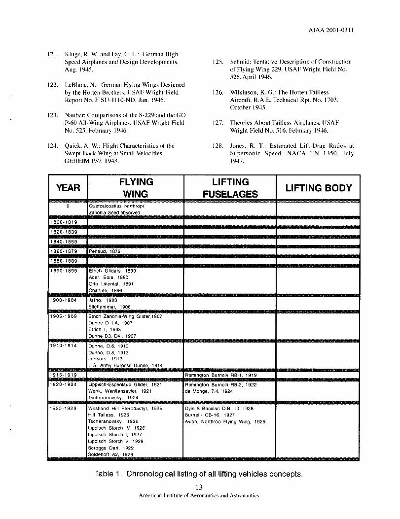
An initial assessment of the histor 3 of AIN identifies
three primary categories as noted in figure 1. These
categories are flying wing, lifting fuselage, and liftingbody. The chart of figure 1 shows that the flying
wing category is the most populous with well over125 aircraft whereas both the lifting fuselage and
lifting bod 3 categories number well under 25 aircraft.
The majority of both the flying wing and lifting
fuselage aircraft were developed prior to 1950whereas the lifting bod 3 work is all post 1950. A
more detailed listing of all of these aircraft is
presented in table I.
A graph of the development time line for the fl3ingwing, lifting fuselage, and lifting body ALV concepts
is presented in figure 2. Noted on the figure, to theright of each AIN type time line, are the countries
that have made significant contributions. It is
interesting to note that the flying wing concept hasbeen under continual development since the late
1800s. The chart also shows that the lifting body
concept has had continued development since itsinception in the late 1950s. However, the lifting
fuselage concept has had a finite life span from the1920s to 1950. The observed start and stops of the
various all lifting vehicle concepts raises severalquestions concerning their influence on one another.
In order to address these questions, it is important
that a shared understanding of what constitutes aflying wing, lifting fuselage, and lifting body is
developed. While both the flying wing and liftingbod 3 concepts are well known by the community the
same can not be said for the lifting fuselage concept.
As a result, it is appropriate at this point to provide abrief discussion of each of the three concepts. Forclarity, photographs of the three concepts are shown
in figure 3.
The pure flying wing is best represented by theNorthrop Grumman B-255"56 as shown in figure 3.
However, for the present discussion, we have relaxedthe definition and will include aircraft that have been
termed both all-wing and tailless, as long as the
subject aircraft does not have a significant fuselageextending fonvard or aft of the wing planform.
The lifting body concept is clearl 3 represented by the
NASA/Northrop M2-F2 as depicted in figure 3.Lifting bod3 concepts are thick aerodynamic shapes
that typically have vertical surfaces for stability andcontrol. Nearly all lifting body development has
The final concept is the lifting fuselage, see figure 3.
The concept depicted is the Burnelli, UB-14, whichat first glance would appear to be out of step _ith this
discussion. However, a review of the lifting fuselage
aircraft design objective and motivation shows amatch with that for the flying wing concepts of the
same time period. These concepts were characterized
by thick airfoil shaped fuselages that were designedto produce a significant portion of the required lift.
Another reason for including these concepts is theirlocation in the ALV time line as depicted in figure 2.
From their chronological location, it is possible that
they greatly influenced both the lifting body and theflying wing work in the United States.
FLYING WING HISTORY
Since the beginning of manned flight, flying wing
designs have been pursued with creativit 3, passion,and braver 3' by man3: visionaries. The earl3
pioneers _ of flight, beginning with Otto Lillienthal ofGerman3, and including Alphonse Penaud of France,Clement Ader of France, and Jacob Ellehammer of
Denmark, recognized the potential of an aircraft
comprised primarily of av¢ing. A review of theirwork shoxvs that the inspiration for much of the initial
efforts came from observations of both plants andbirds. In total, there have been well over 100 l]ying-
wing, manned aircraft developed and flown b3 men
from all parts of the _orld: 3el, the only flying wingaircraft to ever achieve operational deplo3rnent is the
Northrop Grumman B-2.
Presented in figure 4 is the time line of fl3ing wingdevelopment for countries that have made significantcontributions. The chart shows the dominance by
Europe during the first hall" of the 20 'h centur 3. as
mentioned previously. In addition to the pioneeringwork in France, German 3, and England during this
time period, notable accomplishments were alsomade in Switzerland, Denmark, and Austria. Russian
contributions appeared during the 1930s but quicklyended around 1940.
The contributions from the [lnited States have been
sporadic as indicated by the solid and striped bars.The striped bars represent concepts that ma 3 have
contributed to flying wing development, such as thelifting fuselage designs of Burnelli noted b3 the bar
extending from 1920 to 1940. The iifting-bod3 workis represented by the bar extending from 1950 to1980. Additional discussion on the lifting fuselage
concept will be presented later in this section.
3American Institute of Aeronautics and Astronautics

AIAA 2001-0311
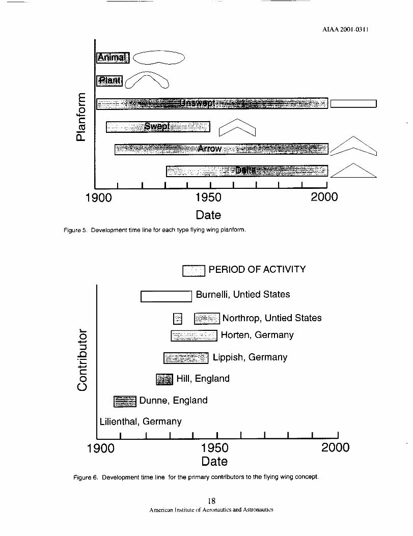
Another interesting trend in flying wing aircraft
development is the history of the aircraft planform as
shown in figure ,5. Flying wing development wasinitially inspired by observations of nature, both in
the form of plant seeds and birds. However, this
concept quickly evolved to include planforms that aremore recognizable today. By 1905, Dunne utilized
untapered swept planforms in an effort to improvethe stability characteristics of flying wings. In 1910,
tapered and swept (arrow) planforms began to
appear. The most aggressive use of the arrow wingplanform is attributed to the Horten brothers of
German)'. The use of the delta planforms for flying
wings is attributed to Lippish in 1930. For present-day, llying-wing designs, the planform of choice is
the arrow-wing planform, which allows for improvedstabilit) and control with high levels of aerodynamic
performance.
As with most aircraft development activities, flyingwing developments prior to 1950 were primarily a
result of individual designers, whereas the work after1950 may be characterized as corporate efforts
involving man) individuals and organizations. Tohighlight the contributions of the individual genius,
the remaining portion of this section of the paper willconcentrate on the work of individual aircraft
designers prior to 1950.
A review of the historical contributions of the more
than 30 prominent flying wing designers, prior to1950, has identified six representative flying wing
designers that have made unique and significantcontributions. These designers also represent thediversity of countries involved in maturing this
aircraft type, see table 2. Included in this list isVincent Burnelli, inventor of the lifting fuselage
concept, because of the apparent influence of hiswork on the flying wing development within the
United States. Table 2 also lists the specificcontribution made by each of the selectedindividuals.
Individual contributors, as a function of time, are
depicted in figure 6. The figure also lists the countryof each of the selected individuals. This chart shows
that of the seven identified designers, three are from
German)' and two each from both England and theUnited States. It is clear from the literature and
available data, that Germany has led the developmentof the flying wing concept. The work of Lillienthal,
Lippish, and the Horten brothers is impressive by allmeasures. The contributions of the English, Dunneand Hill, while not as diverse as the German
influence is extremely notewothy in the area of
stability and control. Contributions by Burnelli and
Northrop of the United States focused on the
maturation and commercial development of the
flying wing concept.
The following subsections will provide additionaldetails and insight into the specific contributions ofthe selected seven individuals and their countries.
Note the information presented does not constitute
detailed biographical and historical information oneach of these individuals. Interested readers should
pursue such information through the many
recognized sources and experts.
German Flying Wings
The diversity of contributions by German aircraftdesigners to the development of the flying wing are
represented by Lillienthal, Lippish, and Reimer andWalter Horten, see figure 7a, b, and c, respectively.The selection of these individuals is not intended to
degrade the contributions of other notable Germandesigners such as Alexander Soldenhoff (originall3from Switzerland) and Jugo Junkers but to portra)
the general historical developments that came from
Germany.
The history of German flying wing development, andin fact manned flight, begins with the inventor.
builder, and pilot, Otto Lillienthal (1848 - 1896), seefigure 7a. Lillienthal's interest in flight began in
1861 with the study of birds. In 1874, OttoLillienthal and his brother, Gustav, showed the
aerodynamic superiority of cambered airfoils. Theirairfoil research continued until 1888 and was
published in 1889. In 1889, Lillienthal turned hisattention to aircraft design and built his first glider.which was used to assess lifting force, but it never
flew. Lillienthal continued to invent, build, and pilot
gliders from 1889 until his death inl896. During thistime period, Lillienthal developed over 10 differentaircraft. While Lillienthal's aircraft were not true
flying wings, most of the designs had a nearly
continuous planform comprised of the bird-like wingand a small aft-located horizontal surface. It is clearfrom the literature that the work of Lillienthal
inspired most early flying wing development in
Europe.
Alexander Lippish (1894-1976) is most noted for hiswork in developing the delta-planform, flying wings
as depicted in figure 7b. Lippish began his flyingwing development work in the late 1920s with the
Storch series of gliders and then transitioned topowered flying wings and the Delta series of flying
wings. Lippish's interest in the delta planform wasdirected at increasing the usable volume of his
designs over that offered by the swept designs of that
4American Institute of Aeronautics and Astronautics

AIAA2001-0311
period. Lippish'spursuitof thisdesignaspectisnotableinEuropebecausemostwereconsumedwithprovingor improvingthe flying wingconcept.Between1927and1945,I,ippishdevelopedover13flyingx_ingaircraft,includingtheDeltaI shownillfigure7b. LippishisalsonotedforhisinterestinapplyingrocketpowertoflyingwingsasnotedbytheDM-Idesignshowninthefigure.
Perhapsthemostprolificof theGermanflyingwingdevelopersweretheHortenbrothers,Reimer(1915-1993)andWalter(1913-1994),seefigure7c5_5'_-__7-_27Between1931and1960theHortenbrothersdevelopedover20flyingwingaircraft,andaswithbothLilienthalandIfippish,theybegantheirworkwithgliders.AndlikeNorthropin theUnitedStates,the Hortenbrothersare notedfor their puristapproachtothedevelopmentoftheflyingwing. TheHortendesignswereextremelyinnovativein shape,controls,andconstruction.A representativeHortengliderandpoweredflyingwing,H XIIIaandH litrespectively,aredepictedin figure7c. Theywerealsothefirstto developa turbo-jetpoweredflyingwing.
England Flying Wines
The pioneering stability and control work of JohnDunne (1875-1949) and the following work by
Geoffrey Hill (1895-1964) characterize the primary
contribution by England to flying wing development.As depicted in figure 8, Dunne's flying wing
development occurred between 1907 and 1914 inwhich he produced more than 6 designs to investigate
completely stable aircraft. Representative of l)unne'sfirst design, a swept-wing tailless bi-plane, the Dunne
D-8 of 1911 is shown in the figure. Dunne iscredited with developing the first practical taillessaircraft. Following on the work of Dunne, Hill also
pursued improved flight safety and stability through
the development of flying wing aircraft. Hilldeveloped a series of aircraft, named the Pterdactyls,between 1924 and 1930 as noted in figure 8. Hill's
Pterdactyl Mk IV was the first tailless to roll and
loop.
United States Flying Wiw, sAs noted in figure 4, the flying wing developmentwithin the United States has been extremely sporadic,
both pre-1950 and post-1950. The pre-1950 timeperiod depicted in figure 4, which is the focus of thisdiscussion, is represented by the work of OctaveChanute at the turn of the century, Vincent Burnelli
(1895-1964), and Jack Northrop (1895-1981). Thisbrief historical discussion will focus on the efforts of
Burnell( _76 from 1919 to 1939 and Northrop 5557,_3-_,7
from 1940 to 1950 as presented in figure 9. At firstglance, it is not obvious as to the relationship of
Burnelli's work, shown in figure 9a, to the fbing
wing development, but upon further inspection, it isclear that both Burnelli and Northrop pursued the
objective of bringing to market the most efficient
aerodynamic shapc, an all-lifting vehicle. Burnelli
recognized the need to have the complete aircraft
provide efficient lift in order to maximize payloadcapacity and range. Burnelli's design approach was
to reshape the fuselage to achieve this goal. Hisefforts resulted in more than 10 operational designs,
see figure 9a. It is clear that Burnelli never produced
a flying wing design but his _ork with lifting
fuselages and thick airfoils did contribute to theflying wing development. It is also interesting to
note that the starting point for Northrop's flying wingefforts ileft side of figure 9b) closely resembles the
Burnelli UB-14 design shown on the right side of
figure 9a.
Northrop's contribution to fbing wing development,
within the United States, is without dispute and iswell documented. Like the Horten brothers of
Germany, Northrop was a purist in his pursuit of the
flying wing, which he labeled the All-Wing. It isbelieved that Northrop's introduction to the flying
wing was through Ton_ Stadlman in the 1920s, while
working at the Douglas Aircraft Compan3. Northropmatured his thoughts and in 1929 his Flying Wing
(with tail) flew, see figure 9b. Northrop continuedhis flying wing development and in 1940 his first
pure flying wing design took fight, the N-IM. From1940 to 1950 Northrop produced more than 10
innovative designs that culminated with the YB 49depicted in figure 9b. Northrop's contributions may
be summarized as a complete aircrafl designer in that
all aspects of flying wing design were successfullyconsidered in developing efficient and cost effective
elegant designs.
UNITED STATES ALV HISTORY
The previous discussion has reviewed the pre-1950development of the flying wing aircraft in an effort to
clarify the role and contributions of varioussignificant contributors. This section of the paper
will draw upon those discussions to develop the ALVhistory. As mentioned previously, a review of the
complete history AINs shows that since 1950 themajority of both flying wing development as well as
flying fuselage development has occurred within theUnited States. Thus, the following discussion on
ALV histor3 will concentrate on the _vork performedsolely within the United States from 1920 to the
present. A pictorial histor 3 of ALV developmentwithin the United States is presented in figures 10a
through 10e.
5
American Institute of Aeronautics and Astronautics

A1AA2001-0311
It is withgreatinterestthattheUnitedStatesALVdevelopmentbeginswithsimilarworkby Burnelli,Staidman,andNorthropin the1920sand1930s,seefigure10a. Burnellipursuedthelifting fuselageconceptfor 20yearsfrom 1919to 1939whereasNorthrop did not see his initial flying wing (with tail)fly until 1929. By 1940 Northrop was beginning to
develop a true flying wing aircraft as represented bythe XB-35 shown in figure 10a. Additional
discussion of these early contributions are providedabove.
The interest in flying wings decreased significantly
during the 1960s and 1970s as focus shifted fromflight vehicle development to space vehicle
development. The initial development of the liftingbody concept is attributed to Alfred Eggers and H.
Julian Harvey, in the ear b 1950s, who wereconducting research on ballistic bodies for lifting
reentry from orbital space flight 1°'77dl6. The researchof Allen and Eggers, along with a handfull of other
NASA engineers, contributed to the body ofknowledge in lifting-body aerodynamics,
thermodynamics, and controls. However, it was notuntil the 1960s that a lifting-body, reentry vehicle
was developed and flown, see figure 10b. TheNASA lifting-body aircraft development activity
grew out of a decision in the early 1960s, by theScientific Advisory Board, to focus on winged
reentry vehicles because of concerns of low speedcontrol characteristics of lifting-body aircraft. Thisdecision drove a number of individuals at NASA to
independently explore the low speed flightcharacteristics of this class of vehicles. The success
of these studies led to the eventual acceptance of
lifting body designs as the preferred approach for
reentry.
At the beginning of 1970s and extending into the1980s, the effort of R. T. Jones, the well known
aerodynamicists, to develop the oblique wing conceptwas a constant theme, as shown in figure 10c 27_'-8_-'_.
The effort by R. T. Jones coincided with the growinginterest within the United States in the developmentof an efficient supersonic transport aircraft. It was
proposed that an oblique flying wing is the optimum
design for a supersonic transport but despite severalsub-scale flight tests and extensive wind tunnel
research the concept was never adopted by theindustry. However. to this day, the oblique wing
design remains the most creative ALV concept everdeveloped.
The 1980s and1990s signaled a new beginning inAIN design interest with the development of the
Space Shuttle, B-2, and F-lIT, see figure 10d. It is
interesting to note that these three ALV conceptswere produced by 3 different companies indicating
the acceptance and maturation of this design
technology. At the time, the Space Shuttle reflectedsignificant advancements in lifting bod3 design
technology and remains an outstanding performingvehicle today. Design of both the B-2 and F-II7
reflect the growing influence of stealth designrequirements and not the pursuit of the flying wing
ALV concept that drove the work by Northrop in the
1940s. However, it is quite evident that the SpaceShuttle design was greatly influenced by the body of
work from the 60s and 70s just as the B-2 and F-117
designs were influenced of Northrop's fl}ing wingdesigns of the 40s and 50s.
As we move into the new century, it is clear that the
AIN concept remains the choice of future vehicles,see figure 10e. The figure show three dist nctly
different ALV concepts that are under developmentwithin the United States. In addition to these
concepts for space travel (X-33), commercial
transportation (BWB), and atmospheric research(PATHFINDER), there are a significant number ofadvanced ALV concepts under consideration for a
variety of military missions. Also note, as with theSpace Shuttle, B-2, and F-117 of figure 10d, each of
these three concepts are under development by threedifferent companies. This observation clearly
indicate that after a century of development the ALV
concept is finally being recognized as the design ofchoice.
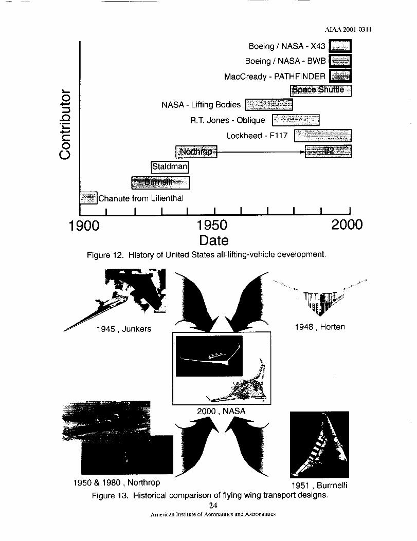
To further explore the relationship between the
various concepts discussed above, a time line of theUntied States ALV concepts is presented in figure 1I.The chart segregates the lifting body, lifting fuselage.
and flying wing categories for clarification. Alsonoted on the chart are bubbles indicating
contributions from other countries. The relationshipsbetween the various contributors is represented byeither a solid or dashed line where a solid linc
indicates a strong linkage and dashed line indicates aweak linkage. A review of this chart indicates thatthere is a strong linkage between the work o1
Burnelli, Stadlman, and Northrop prior to 1950. Forthe recent work there is a strong linkage between the
pre-1950 work and the B-2 and BWB. Based upon
these inferences and linkages, the time line chart o1figure 11 is reformatted into the chart of figure 12that reflects the historical time line for ALV
development in the United States. Based upon thisreview, it is clear the technical leaders (individuals)
in ALV development within the United States areChanute, Stadlman, Burnelli, Northrop, Jones, and
MacCready. Specific information on each of these
6American Institute of Aeronautics and Astronautics

AIAA2001-0311
individualsispresentedin table3. Thisisnottosa}thatotherindividuals,teams,andorganizationshavenotmadesignificantcontributions.Thcproblemisthatthecorporateculturcthatexistsin theaerospaceindustrymakeit extremel3 difficult to identifyindividualaccomplishments.
HISTORICAL COMPARISONS
This final section of the paper will expand on the
discussion presented at the end of the last section (see
figure 12) in which the historical linkages bet_veen
ALV concepts were identified. The study of theselinkages is directed at understanding the lineage of
the present day advanced AIN concepts in the hopeof understanding how the past can assist in
developing the future.
This assessment will be conducted for the Boeing
Blended Wing Body (BWB), the Boeing/NASA X-
43, and the MacCread5 PATHFINDER in figures 13,
14, and 15, respectively.
Presented in figure 13 are historical graphics and
photographs of flying wing transport designs that aresimilar to the current state of the art BWB concept.
The five historical designs selected for comparison tothe BWB date from the 1940s. The similarity
between all six concepts is clearly evident and quitestriking. Each of the designs depicted were
developed based upon similar classical goals:
improved aerodynamic efficiency, increased payload,and reduced weight. Note that all six designs shownin the figure, with the exception of the B-2, have
nearl 3 identical propulsion system layout with theJunkers 1945 design being nearly identical to the
BWB. The Burnelli design of 1951 also has wingletsas does the BWB and an assessment of the aspect
ratio for the various designs shows close similaritybetween the Horten design of 1948 and the BWB. A
dichotomy of conclusions may be drawn from theseobservations that vary from: a good design is
timeless, to the experience collected in the past iseither unknown, forgotten, or at the least ill-judged.
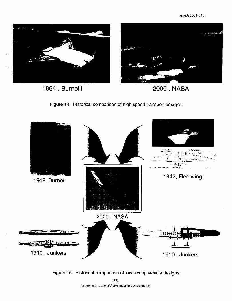
A comparison of a historical high speed transport
design of Burnelli from 1964 to the Boeing/NASAX-43 concept is presented in figure 14. As with the
designs presented in the previous figure, there is a
striking similarity betxveen the 1964 design and theX-43. Both designs are characterized by a slab-likelifting body/fuselage, aft mounted delta wing, and
twin vertical tails. The Burnelli design is unique inthat it shows a canard and winglets on both the xving
and canard. Even though there is a striking similarityin the two designs, the Burnelli concept is a
supersonic cruise design whereas the X-43 is ahypersonic cruise design. This difference in design
objective results in a broader function of the body lk_r
the X-43 design compared to the Burnelli concept.The X-43 design utilizes the body for both lift
generation and as a pre-compression surface for the
engine inlet flow whereas the Burnelli design isfocused only on body lift generation. The same
dichotomy of conclusions may be drawn from theseobservations.
Presented in figure 15 is a comparison of a variety of
historical graphics of low sweep flying wing designsto the PATHFINDER. The four historical designs,
selected for comparison to the Pathfinder, date from1910 and include the first flying wing patent b5 Hugo
Junkers (Ioxver left of figure). However. unlike the
striking similarit 5 betxseen the designs depicted in theprevious txso figures, there are significant differences
between the low-sweep, flying wing designs shown.Also note that each of the four historical designs are
for a large transport aircraft svhere the Pathfinder
design is a very narrosvly designed research vehicle.
All five designs shown in the figure have nearlyidentical planform, with the Junkers 1910 flying wing
design (bottom left) being nearly identical to thePathfinder. The other three historical designs have a
propulsion system layout that is similar to thePathfinder, yet they differ from the Pathfinder design
in that they have vertical surfaces for control. Alsonote that the Junkers design of 1910 and the Burnelli
design of 1942 also have a separate horizontal control
surface. Based upon this review, it ma_ be concludedthat a good design is timeless.
CONCLUDING REMARKS
The historical review of AIN indicates that we
continue to re-create the past instead of learning from
the past to create the future. These sentiments are
clearly stated through the following quotes from A.R. Weyl, 1944.
"...Flying Wing. in which at the present period moreinterest than ever is being displayed."
"...it seems a fact that experience collected in the past
with tailless aeroplanes is either unknown orforgotten or. at the least ill-judged..."
"...it is by no means sufficient that a crazy design
flies; it must fly far better than everything else inorder to raise attention among those closedcircles..."
7American Institute of Aeronautics and Astronautics

AIAA2001-0311
2.
.
4.
.
6.
7,
8.
9.
10.
11.
12.
13.
14.
15.
REFERENCES
Anderson, J. D. Jr.: A History of
Aerodynamics and Its Impact on FlyingMachines. 1997.
Angetucci, E.: Airplanes from the l)awn of
Hight to the Present Day. 1971.
Bowers, E M.: Unconventional Aircraft.
Chant, C.: Aviation an Illustrated History.1980.
Gibbs-Smith, C. H.: Aviation - An Historical
Survey from its Origins to the End of WorldWar II. 1985
Lange, R. H.: Survey of Unconventional
Aircraft Design Concepts. NVvL Symposium
April 1987.
Lange, R. H.: Review of Unconventional
Aircraft Design Concepts. AIAA Journal ofAircraft, vol. 25, no. 5, pp. 385 - 392. May1988.
Maddock, 1.A.: A History of MannedPowered Hying Wing Development: 1922-1999. SAE 199-01-5657. 1999 WorldAviation Conference October 19-21, 1999.
Pinson, J. D.: Diamond Jubilee of Powered
Hight; The Evolution of Aircraft Design.Dayton-Cincinnati Section AIAA with AirForce Museum. December ! 4-15, 1978.
Reed, D. B.: Wingless Flight, The Lifting
Body Story. NASA SP-4220. 1997.
Rolfe, Dawydoff, Winter, Byshyn, and Clark:
Airplanes of the World 1490 to 1969. 1969.
Roskam, J.: What Drives Unique
Configurations. SAE Paper 88 ! 353, 1988.
Taylor, M. and Mondey, D.: Aircraft Facts &Feats. 1984.
Traylor, J. W. R.: Air Facts and Feats. 1974.
Wooldridge, E. T.: Winged Wonders The
Story of the Flying Wings. 1983
16.
17.
18.
19.
20.
21.
22.
23.
24.
25.
26.
Ankenbruck, H. O. and McKinney, M. O. Jr.:Generalized Performance Comparison of
Large Conventional, Tail-Boom, and Tailless
Airplanes. NACA TN No. 1477. October1947.
Bicher, R. E B. Jr,: Trends of Development in
Flying Wing and Tailess Aircraft. USAF
Wright Field Technical Report No. F-TR- 101-DN, February, 1946.
Brewer, G. W. and May, R. W. Jr.:
Investigation of a l/7-Scale Powered Model of
a Twin-Boom Airplane and a Comparison ofits Stability', Control, and Performance with
Those of a Similar All-Wing Airplane. NACATN 1649, 1948.
Brewer, G. W.: An Estimation of the Flying
Qualities of the Kaiser Fleetwing All-Wing
Airplane from Tests of a I/7-Scale ModelTED NO. NACA 2340, NACA RM No.
L6J !8, Nov. !946.
Brewer, G. W. and Rickey, E. A.; Tests of al/7-Scale Powered Model of the Kaiser
Tailless Airplane in the Langley Full-ScaleTunnel. NACA MR No. L6C13, 1946.
Buckstrom, A. A.: The Elements of Tailless
Airplane Design. Sport Aviation, pp. 39-44,May 1979.
Campbell, J. E and Seacord, C. L. Jr.:
Determination of the Stability and ControlChasracterisitics of a Tailless All-Wing
Airplane Model with Sweepback in theLangley Free-Flight Tunnel. NACA ACR No.
L5A 13. February 1945.
Cox, W. J., Siddall, J. N. and Stephenson, T.E.: A Tailless Research Aircraft. Aircraft
Engineering. Pp. 184-190.
Dillworth, J. A.: Japanese Tailless Aircraftand Theoretical Work on Spiral Instability,.
USAF Wright Field Report No. F-IR-109-RE.
August 1946.
Donlan, C. J.: An Interim Report on the
Stability and Control of Tailless Airplanes.NACA Report No. 796.
Holbrook, C. T.: Some Studies of Flying
Wings. Mississippi State College April a950.
8American Institute of Aeronautics and Astronautics
AIAA2001-0311
27.
28.
29.
30.
31.
32.
33.
34.
35.
36.
37.
Jones,R.T.:Noteson the Stability and
Control of Tailless Airplanes. NACA TN 837,December 1941.
Kidd, E. A.: Longitudinal and LateralDirectional Stability l)erivatives of the N-
9MB Flying Wing Airplane as Obtained fromFlight Tests. Cornell Aeronautical l._boratory,
Report No. TB-559-F-I, October 1949.
Krinfeld, R.: Test Flying a Tailless Glider. The
Aeroplane, pp 367-369, April 11, 1947.
Marske, J. J.: Handling and PerformanceCharacteristics of Swept-Forward Flying Wing
Aircraft. SAE Paper 750748, April 1975.
Murray, C.V.: Full Scale Research on a
Hying Wing. Aircraft Engineering. Pp. 144-148.
Noggle, L. W. and Jobe, ('. E.: l,arge-VehicleConcepts. Astro. And Aero, vol. 17, April
1979, pp. 26-32.
Nonweiler, T. : German High Speed Aircraftand Guided Missiles Part II Guided Missiles.
Report No. EA. 251/2 Aerro 2071., Aug.1945.
Pitkin, M. and Meggin, B.: Analysis of Factors
Affecting Net Lift Increment Attainable withTrailing-Edge Split Flaps on Tailless
Airplanes. NACA ARR No. 1,4118.September 1944.
Seacord, C. L. Jr. and Ankenbruck, H. O.:
Effect of Wing Modifications on theLongitudinal Stability' of a Tailless All-Wing
Airplane Model. NACA ACR No. L5G23.September 1945.
Seacord, C. L. Jr. and Ankenbruck, H. O.:
Determination of the Stability and ControlChasracterisitics of a Straight-Wing,Tailless
Fighter- Airplane Model in the Langley Free-Flight Tunnel. NACA ACR No. 1,5K05.
February 1946.
Sone, R. W. Jr. and Hultz, B. E.: Summary ofSpin and Recovery' Characterisitics of 12Models of Flying-Wing and Unconventional-
Type Airplanes. NACA RM L50L29, March1951.
38.
39.
40.
41.
42.
43.
44.
45.
46.
47.
48.
49.
50.
51.
WeyI,A. R.: The Biology of the FlyingSaucer - I. ]'he Aeroplane pp. 185-187.
Fcbruar 3 13, 1948.
Weyl, A. R.: The Biolog3 of the Flying
Saucer - I1. The Aeroplane pp. 279-282. March3, 1948.
Weyl, A. R.: The Biolog 3 of the Flying
Saucer - III. The Aeroplane pp. 337-339.March 19, 1948.
Wey/, A. R.: The Biology of the Flying
Saucer - IV. ]'he Aeroplane pp. 385-387. April2, 1948.
Weyl, A. R.: Stability of Tailless Aeroplanes.
Aircraft Engineering, pp. 73-81, March 1945,
pp. 103-111.April 1945.
Report of Wind Tunnel Tests on the Kaiser
Flying Wing. Wind Tuinnel Report No. 590,
Wright Brother Wind Tunnel M.I.T., Ma 31943.
Preview of the Future: the ArmstrongWhitworlh A. W. 52, Jan. 16, 1948.
Rel_rt H-81 Calculated Performance KaiserFly'ing Wing Airplane. October 1943.
Tailless Research with T_vin Jets. The
Aeroplane pp. 73-777. Februar 3 16, 1948.
Lademann, R. W. E.: Development ofTailess
and All-Wing Glidrs and Airplanes. NACATM No. 666. April 1932.
Nickel. K. and Wohlfahart, M.: Tailless
Aircraft in Theory: and Practice. AIAA 1997.
Callaghan, J. T. and Liebeck, R.H.: SomeThoughts onb the Design of Subsonic
Transport Aircraft for the 21 '_ century. SAEPaper No. 901987. October 1990.
Liebeck, R. H., Page M. A., and Rawdon, B.
K.: Blended-Wing-Body SubsonicCommercial Transport. AIAA 98-(M38.
January' 1998.
Ifiebeck, R. H., Page, M. A., Rawdon, B. K.,
Scott, E W., and Wright, R.A.: Concepts forAdvanced Subsonic Transports. NASA CR
4624, September 1994.
9American Institute of Aeronautics and Astronautics

AIAA2001-0311
52. Potsdam,M.A..Page,M.A.,andLiebeck,R.H.: BlendedWingBodyAnalysisandDesign.AIAA-97-2317.
53.Whitehead,R.E.:SubsonicTransportation,PresentationtotheAeronauticsAdvisor3'Committee.NASAOfliceofAeronauticsandSpaceTechnology.October21,1992.
54.Weyl,A.R.:TaillessAircraftandFlyingWings-AStudyofTheirEvolutionandTheirProblems.AircraftEngineering,pp.3'40-352,December1944,pp.8-12.January1945,pp.41-46,February1945.
55. Allen,R.S.:TheNorthropStory;1929-1939.NewYork;Orion,1990.
56. Anderson, E: Northrop: An Aeronautical
Nistory. Los Angelas; Northrop. 1976.
57. Begin, L.: The Northrop Flying Wing
Prototypes. AIAA Paper 83-1047, 1983.
58. Horten, R. and Selinger, P. F.: Nurflugel - Die
Geschichte der Horten-Flugzeuge 1933-1960.1983.
59. Kohn, L.: The Flying Wings of Northrop.Milwaukee: Aviation Publications. 1974.
60. lx)ngyard, W. H.: Who's Who In Aviation
History: 500 Biographies.
61. McLarren, R.: Low Drag Accented in All-
Wing. Aviation Week. Dec. 20, 1948.
62. Myhra, D.: The Horten Brothers and TheirAll-Wing Aircraft. 1998.
63. Northrop, J. K.: The Development of All-Wing Aircraft. 35 thWilbur Wright Memorial
Lecture. The Royal Aeronautical Society
Journal, Vol. 5 t, pp. 481-5 !0, 1947.
64. Northrop, J.: The Northrop XB-35 HyingWing Superbomber. Aviation, Aug. 1946.
65. Northrop, J.: The All-Wing Type Aircraft.Aviation, 29 March 1930.
66. Pape, G. and Campbell, J.: Northrop HyingWings: A History of Jack Northrop's Visionary
Aircraft. Atglen, PA: Schiffer, 1995.
67.
68.
69.
70.
71.
72.
73.
74.
75.
76.
Sears, W. R.: Flying Wing Airplanes: The XB-
35/YB-49 Program. AIAA Paper 80-3036,1980.
Von Karmen, T. and Edson, L.: The Wind and
Beyond: Theodore von Karmen. Boston: LittleBrown. ! 967.
Feigenbaum, D.: Estimation of thePerformance and Longitundianl Stability and
Control of a Lifting-Body Type of CargoAirplane from Tests of Simplified Models.
NACA Wartime Report MR No. L5EO9a. L-541. June 1945.
Harris, T. A.: Wind Tunnel Tests of l/7-Scale
Model of the Burnelli Single Boom AttackBomber, X-18-B1. NACA CR 1105.5 Burnelli18B-I/1. June 16 1939.
Jacobs, E. N. and Sherman, A: Wing-Fuselage
Interference - Comparison of Conventionaland Airfoil-Type-Fuselage Combinations.
NACA Wartime Report L - 509 ARC March1937
Klemin, Alexander, and Ruffner, Benjamin:
Lift Slope and Distribution on BurnelliAeroplanes. The Aircraft Engineer, vol. XII,
no. 6, (Supp. To Flight) June 18, 1936, pp.652a-652c.
Laitone, E. V.: A High-Speed Investigation ofthe Burnelli XB-AB-3 Model in the N.A.C.A.
8-Foot High-Speed Wind Tunnel. NACA
Report l l05.5:Burnelli/BAB-3/2. June 19,1940.
Neihouse, A. I. and Harmon, S. M.: SpinTests of a 1/24-Scale Model of the Burnelli
XB-AB-3 Airplane. NACA CR 1105.5
Burnelli BAB-3/I. August 2, 1940.
Wenzinger, C. J. and Harris, T. A.: WindTunnel Tests of i/7-Scale Model of the
Burnelli Twin Boom Attack Bomber, XB-17-
BI. NACA CR 1105.5 Burnelli 17B-I/I. May8, 1939.
1105.5; Burnelli/BAB-3/3. XB-AB-3 windtunnel model coordinates. Burnelli Aircraft
Company. Guggenheim School ofAeronautics. Report on Wind Tunnel Test No.
687-H. October 25, 1937.
10American Institute of Aeronautics and Astronautics

AIAA 2001-0311
77.
78.
79.
80.
81.
82.
83.
84.
85.
86.
Allen, H. J. and Eggers, A. J.: A Study of the
Motion and Aerodynamic Heating of Missiles
Entering the Earths Atmosphere at High
Supersonic Speeds. NACA RM A53D28,1953.
Allen, H. J. and Eggers, A. J.: A Study of the
Motion and Aerodynamic Heating of MissilesEntering the Earths Atmosphere at High
Supersonic Speeds. NACA TN 4047, 1957.
Allen, H. J. and Eggers, A. J.: A Study of the
Motion and Aerodynamic Heating of MissilesEntering the Earths Atmosphere at High
Supersonic Speeds. NACA Reix)rt, 1958
Bertram, M. H. and McCauley, W. D.: An
Investigation of the AerodyanmicCharacteristics of Thin Delta Wings with aSymmetrical Double-Wedge Section at aMach Number of 6.9, NACA RM L55BI4,1955.
Cruz, C. I. and Ware, G. M.: Control
Effectiveness and Tip-Fin Dihedral Effects for
the HL-20 Lifting Body Configuration atMach Numbers From 1.6 to 4.5. NASA TM
4697, 1995.
Dennis, D. H. and Cunningham, B. E.: Forcesand Moments on Inclined Bodies at Mach
Numbers from 3.0 to 6.3. NACA RM A54E03,1954.
Dennis, D. H. and Cunningham, B. E.: Forcesand Moments on Pointed and Blunt-NosedBodies of Revolution at Mach Numbers from
2.75 to 5.00. NACA RM A52E22, 1952.
Eggers, A. J, Hansen, C. F., and Cunningham,B. E.: The Effect of Yaw and Heat Transfer to
a C) lindrical Stagnation region in HspersonicFlow. NACA RM A55E02, 1955.
Eggers, A. J. and Syvertson, C. A.: AircraftConfigurations I)eveloping High Lift-DragRatios at High Supersonic Speeds. NACA RMA55L05, 1956.
Eggers, A. J., Resnikoff, M. M. and Dennis, D.H.: Bodies of Revolution Having Minimum
Drag at High Supersonic Airspeeds. NACAReport 1306, 1957.
87.
88.
89.
90.
91.
92.
93.
94,
95.
96.
97.
Eggers, A. J. and Syvertson, C. A.:
Experimental Investigation of a Body Flare forObtaining Pitch Stability and a Body Flap for
Obtaining Pitch Control in Hypersonic Flight.NACA RM A54JI3, Jan. 1955.
Eggers. A. J., Allen, H. J., and Neice, S. E.: AComparative Analysis of the Performance of
Long-Range Hypervelocit 3 Vehicles. NA('ARM A54LI0, March 1955.
Eggers, A. J. and Savin, R. C.: ApproximateMethods for Calculating the Flow about
Nonlifting Bodies of Revolution at HighSupersonic Airspeeds. NACA TN 2579.Decmebr 195 I.
Epstein, P. S. : On the Air resistance of
Projectiles. Proceedings of National Academyof Sciences, 1931, vol. 17, pp. 532-547.
Ferrari, C.: The Determination of the Projectileof Minimum Wave Resistance. Reale
Academia della Science de Torino Atti. 1939
Hax, A. H. and Lawrence, H. R.: The
Aerodynamics of Low Aspect Ratio Wings
and Wing-Body Combinations. CAL ReportNo. CAL-37, 1951.
Gowen, E E. and Perkins, E. W.: I)mg of
Circular Cylinders for a Wide Range ofReynolds Numbers and Mach Numbers.NACATN 2960, 1953.
Grimminger, G., Williams, E. R, and Young,G. B. W.: Lift on Inclined Bodies of
Revolution in Hypersonic FIo_v. Jour Acro.Sci., vol. 17, no. 1 I, Nov. 1950, pp. 675-690.
Hodges, A. J.: The Drag Coefficient of Vcr_
High Vehxzit3 Spheres. Jour. Aero. Sci., vol.24, no. 10, Oct. 1957, pp. 755-758.
Hsue-Shen Tsien: Supersonic Flow Over an
Inclined Body of Revolution. Journal of Aero.Sci., 1938, pp. 480-483.
Jack, J. R. and Gould, I,. I.: Aerodynamics ofSlender Bodies at Mach Number of 3.12 and
Reynolds Numbers from 2x10 to 15x10 - I1 -Aerodynamics Load Distributions of Series of
Five Bodies Having Conical Noses and
Cylindrical Afterbodies. NACA RM E52('10,1952.
11American Institute of Aeronautics and Astronautics

AIAA 2001-0311
98.
99.
100.
101.
102.
103.
104.
105.
106.
107.
108.
Klunker, E. B. and Harder, K. C.: SomeConsiderations of the Influence of Body
Cross-Sectional Shape on the LiftingEfficiency of Wing-Body Combinations at
Supersonic Speeds. NACA RM L56H30,1956.
Lazzeroni, E A: Investigation of a MissileAirframe with Control Surfaces Consisting of
Projecting Quadrants of the Nose Cone.NACA RM A53L21, 1954.
Lighthill, M.J.: Supersonic How Past Bodiesof Revolution. R&M No. 2003, British ARC
1945.
109.
I10.
I11.
Seiff, A., Sandahl, C. A., Chapman, D. R.,
Perkins, E. W., and Gowen, E E.:
Aerodynamic Characterisitcs of Bodies atSupersonic Speeds - A Collection of Three
Papers. NACA RM A51J25, Nov. 1951.
Sibulkin, M.: Heat Transfer Near the Forward
Stagnation Point of a Body of Revolution.Jour. Aero. Sci., vol. 19, no. 8, Aug, 1952, pp.570-571.
Van Dyke, M. D.: Practical Calculation of
Second-Order Supersonic Flow PastNonlifting Bodies of Revolution. NACA TN
27_, July 1952.
Malina, E J. and Summerfield, M.: The
Problem of Escape from the Earth by Rocket.Jour. Aero. Sci., vol. 14, no. 8, Aug. 1947, pp.471-480.
112. Vincenti, W. G. and Wagoner, C. B.:Transonic Flow Past a Wedge Profile with
detached Bow Wave. NACA Report 1095,1952.
Moeckel, W. E.: Flow Separation Ahead of a
Blunt Axially Symmetric Body at MachNumbers !.76 to 2.10. NACA RM E51125,
December 1951.
Moeckel, W. E.: Flow Separation Ahead ofBlunt Bodies at Supersonic Speeds. NACATN 2418, 1951.
Osborne, R. S. and Wright, J. B.: Tests of
Lifting Surfaces on Conical and CylindricalPortions of a Body at Supersonic MachNumbers and at a Mach Number of 1.2.
NACA RM L9F29, 1949.
113.
114.
115.
Von Karman, T. and Moore, N. B.: Resistance
of Slender Bodies Moving With Supersonic
Velocities, With Special Reference toProjectiles. Transaction of the American
Society of Mech Engr. APM-54-27, 1932.
Ward, G. N.: Supersonic Flow Past SlenderPointed Bodies. Quart. Jour. Mech. and Appl.
Math, Vol. II, pt. 1, March 1949. pp. 75-99.
Ware, G. M. and Cruz, C. I.: AerodynamicCharacterisitics of the HL-20. Journal of
Spacecraft And Rockets, vol. 30, no. 5, Sept-
Oct 1993, pp. 529-536.
Penland, J.A.: Aerodynamic Characterisiticsof Circular Cylinders at Mach Number 6.86
and Angles of Attack up to 90 °. NACA RML54A 14, 1954.
Resnikoff, M. M.: Optimum Lifting Bodies at
high Supersonic Airspeeds. NACA RM
A54BI5, May 1954.
Sears, W. R.: On Projectiles of Minimum
Wave Drag. Quart. Of Applied Math, Vol. IV,
no. 4, Jan. 1947, pp. 361-366.
Seiff, A. and Allen, H. J.: Some Aspects of
the Design of Hypersonic Boost-GlideAircraft. NACA RM A55E26. Aug. 1955.
116. Perkins, E. W., Jorgensen, L. H., and Sommer,S.C.: Investigation of the Drag of Various
Axially Symmetric Nose Shapes of FinenessRation 3 for Mach Numbers from 1.24 to 7.4.
NACA Report 1386. 1958.
117. Biot, M. A. and Jayne, J. M.: Horten TaillessAircraft. Office of the Publication Board,
Dept. of Commerce Report No. 258.
118. Dabrowski, H-P: Flying Wings of the Horten
Brothers. Schiffer Military/Aviation History.1995.
119. Horten Brothers: Ten Years Development of
the Flying-Wing High Speed Fighter. Chance
Vought Aircraft Report No. LGB 164.
120. Horten: Flying Wing Interceptor. CN-153578,March 1945.
12
American Institute of Aeronautics and Astronautics
AIAA 2001-0311
121.
122.
123.
124.
Kluge, R. W. and Fay, C. I,.: German High
Speed Airplanes and Design Developments.
Aug. 1945.
LeBlanc, N.: German Flying Wings Designed
b) the Horten Brothers. [ISAF Wright Field
Rcport No. F-SLI-IIIO-ND, Jan. 1946.
Nauber: Comparisons of the 8-229 and the GO
P-60 All-Wing Airplanes. USAF Wright Field
No. 525. February 1946.
Quick, A. W.: Flight Characteristics of the
Swept-Back Wing at Small Velocities.
GEHEIM P37. 1943.
125.
126.
127.
128.
Schmid: Tentative Description of Construction
of FI3ing Wing 229. USAF Wright Field No.
526. April 1946.
Wilkinson, K. G.: The Horten Tailless
Aircraft. R.A.E. Technical Rpt. No. 1703.
October 1945.
Theories About Tailless Airplanes. IISAF
Wright Field No. 516. February 1946.
Jones, R. T.: Estimated Lift-Drag Ratios at
Supersonic Speed. NACA TN 1350. July
1947.
YEAR
0
1800-1819
1820-1839
1840-1859
1860-1879
1880-1889
1890-1899
1900-1904
1905-1909
FLYING
WINGQuetzalcoatlus northropi
Zanonia Seed observed
II
Penaud, 1876
Etrich Gliders, 1890
Ader, Eole, 1890
Otto Liliental, 1891
Chanute, 1896
Jatho, 1903
Ellehammer, 1906E']' ....
Etrich Zanonia-Wing Glider,1907
Dunne D-I.A, 1907
Etrich I, 1908
Dunne D3, D4 , 1907
1910-1914 Dunne, D.6, 1910
Dunne, D.8, 1912
Junkers, 1913
U_S: Army Burgess Dunne, 1914
19t5-1919
1920-1924 Lippisch-Espenlaub Glider, 1921
Wenk, Wenltenseyler, 1921
Tscheranovsky, 1924
1925-1929 Westiand Hill Pterodactyl, 1925
Hill TaJless, 1926
Tscheranovsky, 1926
Lippisch Storch IV, 1926
Lippisch Storch I, 1927
Lippisch Storch V, 1929
Scroggs Dart, 1929
:Soldehoft A2, 1929
LIFTING
FUSELAGES
Iltlltlllr,iTTi? ¸
LIFTING BODY
I1' II ¸¸ I
ivr--ww i I
]ml_ ...... NIH!il.......................... [l! ].!....
Rem!ngton Burnelli RB-1, 1919
iRemington Burnelli RB-2, 1922
de Monge, 7.4, 1924
Dyle & Bacalan D.B. 10, 1926
Burnelli CB-16, 1927
Avion, Northrop Flying Wing, 1929
Table 1. Chronological listing of all lifting vehicles concepts.
13American Institute of Aeronautics and Astronautics

AiAA 2001-0311
1930-1934
1935-1939
1940-1944
! !!! !!?1945-1949
1950-1954
1955-1959
1960-1964
1965-1969
Jl1970-1974
1975-1979IIIIIIIIIIIII I III m
1980-1984' ITrlll
1985-1989
1990-1994
1995-1999'/l'/ll_2000-2004
FLYINGWING
Lippisch Delta 1, 1930
Junkers, G-38, 1930
Fauvel AV2. 1930
Soldehoft A4, 1931
Horten Ho I, 1933
Arup No. 1,2,3,4, 1932
Westland Hill, 1934
Tcheranov.sky Blch-3, 1934 .................
Horten Ho II, 1935
Waterman Arrowplane, 1935
Canova All-Wing, 1935
Horten Ho V, 1936
Waterman Arrowbile, 1937
Japanese, HK-1, 1938
Horten Ho III, 1938
Tcheranoveky Blch-2O, 1938
Handley Pa_e HP 75 MANX, 1938i
Horlen Ho IV, 1940
Lippisch DFS 194, 1940
Northrop N1M, 1940
Japanese, KU-2, 1941
Japanese, KU-3, 1941
Northrop N9M, 1942
Vought V-173, 1942
Handley Page Manx, 1943Messerschmitt Me163 Komet.1943
Horten HO VII, 1943
Northrop XP-56, 1943
Horten Ho XlII, 1943
Horten Ho Vl, 1944
Horten Ho Xll, 1944
Northrop MX324/334, 1944iiiiiiiBii III IIII I
Horten/Gotha Ho IX, 1945
Northrop XP-79B, 1945
Uppish DM-1, 1945
Japanese, JSM1, 1945G,A,L,/56, 1946
Northrop XB-35, 1946
Northrop YB-49, 1947
Horton Ho Xve, 1948
Whilworth A, W, 52, 19481111111111
Horten Colibri Ho XVI , 1950
De Haviland DH 108, 1950
Northrop X4, 1950
Chance Vought, 1950
Chance Vought CV-XF5U-1, 1950
Fauvel AV-36, 1951
Saab 35 Draken, 1951
Avro 698, 1953
Horton Motorglicler, 1953
Horten HW-X-26-52, 1954
I'1
Mitchel Wing B10, 1960
Horton I/Ae.38, 1960
Ha,dley Page Slewed Win_, 1961
Dyke JD-1 Delta, 1965
'1 I
LIFTING
FUSELAGESBurnelli VB-20, 1930
Burnelli UB-14, 1935
Bumelli CBY-3, 1939
II ] IIII1nHril'
i,
Dyke JD-1 Delta, 1965
Rogallo Wings, 1970
trill
mSawyer Skyjacker, 1975
Lockheed Fl17
Horton Pulio, 1987
Northrop B-2, 1988I roll
McDonnell Douglas A19
Lkhd/Martin A17
mHmmHI!l
LIFTING BODY
IIH
I tit _ _1111MillNASA M2-F1, 1963
ttltllNASA M2F2. 1966
NASA HL-10, 1966
NASA X-24A, 1969,II
NASA M2F3, 1970
NASA X-24B, 1973
Lockheed X-38
Lockheed X-33
Table 1. Concluded.14
American Institute of Aeronautics and Astronautics

AIAA2001-0311
Lilienthal:(1848-1896)
Dunne:(1875-1949)
Burnelli:(1895-1964)
Hill:(1895-1956)
Uppish:(1894-1976)
Horten:(1913-1994)
Northrop:(1895-1981)
Developed first all wing glider. First sustainedcontrolled flight in history.
First to address flying wing S&C issues.
Developed lifting fuselage concept for largepayload and volume.
First successful practical tailless aircraft.Resolved S&C and stalling of flying wing.
Developed delta flying wing concepts.
Developed arrow flying wing concepts.
Matured the flying wing concept.
Table 2. Listing of flying wing primary contributors.
Chanute:(1832-1910)
Staldman:(1885-1982)
Burnelli:(1895-1964)
Northrop:(1895-1981)
R. T. Jones:
MacCready"
Brought Lilienthal's (flying wing) work to U.S.
First advocate for flying wing aircraft in U.S.
Developed lifting fuselage concept.
Matured flying wing concept.
Developed oblique wing concept.
Developed advanced UAV concept.
Table 3. Primary individual contributors to the United States all-lifting-vehicle concepts.
15American Institute of Aeronautics and Astronautics

125
100
75NumberAircraft
Concepts 50
25
0Flying Lifting LiftingWing Fuselage Body
AIAA 2001-0311
DATES
1900 to 1950
1951 to 2000
Figure 1. Number of all-lifting-vehicle aircraft developed since 1900.
c_
#,B
O
>
1900
United States
I
1950
Date
United States
EnglandFrance
GermanyRussiaUnited States
I
2O0O
Figure 2. Development time line for each type of all-lifting-vehicle aircraft.
16American Institute of Aeronautics and Astronautics

AIAA2001-0311
FLYING WING
Northrop, B-2, 1980
LIFTING FUSELAGE
Bumelli, UB-14, 1934
Figure 3. Representative ALV concepts.
LIFTING BODY
NASA/Northrop, M2-F2, 1966
OO
Figure 4.
I i_ll Untied States ! !1
Russia
!_::_ Germany
;_ :::-I France
England
Development time line for each of the primary contributing countries of flying wing aircraft.
17American Institute of Aeronautics and Astronautics
I I I I
1900 1950 2000
Date
AIAA 2001-0311
EO
t--
m
n
1900
I I
I ........................ ...... i z j _ ql-i_ .........
I I I I I I I I I I1950 2000
DateFigure 5. Development time line for each type flying wing planform.
PERIOD OF ACTIVITY
O
d3im
O
I ] Burnelli, Untied States
Northrop, Untied States
I dI Horten, Germany
I I Lippish, Germany
Hill, England
Dunne, England
Lilienthal, Germany
I I I
1900I I I I I I
195ODate
Figure 6, Development time line for the primary contributors to the flying wing concept.
I
2OO0
18American Institute of Aeronautics and Astronautics

AIAA2001-0311
No. DESIGNS: - 17
(a) Otto killienthal
Delta I
(b) Alexander Lippish
DM- I
H-XIIIa
(c) Reimer and Wilber Horten
Figure 7. Germany's primary contributors of flying wing aircraft.
19
American Institute of Aeronautics and Astronautics
H-III

AIAA 2001-0311
John Dunne - D 8
Figure 8. England's primary contributors of flying wing aircraft.
Geoffrey Hill - Pterodactyl Mk 1
RB - 1(a). Vincent Burnelli
UB - 14
Flying Wing
(b). Jack Northrop.
Figure 9. United States primary contributors of flying wing aircraft.
20American Institute of Aeronautics and Astronautics
YB - 49

AIAA 2001-031 !
Bumelli, UB- 14Lifting Fuselage
Northrop, Flying Wing
Stadlman Northrop, XB-35Flying Wing
(a) Lifting Fuselage and Flying Wing, 1920 to 1950.
(b) Lifting Body, 1960 to 1970.
Figure 10. Diversity of United States all-lifting-vehicle aircraft.
21American Institute of Aeronautics and Astronautics

AIAA2001-0311
R. T. Jones, AD-1
(c) Oblique Flying Wing, 1970 to 1980.
Figure 10.
B-2
Flying Wing
S pace ShuttleLifting Body
(d)
continued.
Flying Wing and Lifting Body, 1980 to 1990.
22American Institute of Aeronautics and Astronautics
F-117
Flying Wing

AIAA 2001-0311
X-33
Lifting Body
Pathfinder Blended Wing Body (BWB)Flying Wing Flying Wing
(e) Flying Wing and Lifting Body, 1990 to 2000.
Figure 10. concluded.
LiftingBody
LiftingFuselage
Germany
FlyingWing
Russia
C_anute
1900
Staldman
from Lilienthal
I I I I I
1950Date
Figure 11. History of United States all-lifting-vehicle concepts.23
American Institute of Aeronautics and Astronautics
I I I I
2000
AIAA 2001-0311
O
_3.13li
c-O
¢D
Boeing / NASA - X43
Boeing / NASA - BWB D
MacCready- PATHFINDER
I_ _ _1NASA- Lifting Bodies I!_
R.T. Jones-Oblique I:_!_q_,_-i_:l
Lockheed- Fl17 I_i_
ISta'dmanI
_Chanute from Lilienthal
I I I I I1900 1950
DateFigure 12.
.I i-I
I I I I i2000
History of United States all-lifting-vehicle development.
1948, Hoaen
20O0, NASA
1950 & 1980, Northrop 1951, Burrnelli
Figure 13. Historical comparison of flying wing transport designs.24
American Institute of Aeronautics and Astronautics
AIAA2001-031!
1964, Burnelli 2000, NASA
Figure 14. Historical comparison of high speed transport designs.
1942, Burnelli
.......... o, I i I _ _ "'"
1942, Fleetwing
2OOO, NASA
s,<_[:x:3 _i _ '..><J>,O------._
1910, Junkers 1910, Junkers
Figure 15. Historical comparison of low sweep vehicle designs.
25American Institute of Aeronautics and Astronautics

Related Documents