38ARZ/ARD Commercial Air-Cooled Split System Product Data The 38ARZ/ARD condensing units with scroll compressors match Carrier’s 40RM indoor-air handlers for a wide selection of dependable commercial cooling solutions. Carrier’s air-cooled split systems: • provide a logical solution for commercial needs • have a rugged, dependable construction Features/Benefits These dependable split systems match Carrier’s indoor-air handlers and direct- expansion coils with outdoor condensing units for a wide selection of commercial cooling solutions. Up to 11.0 EER The high efficiency split commercial split system combining the 38ARZ/ARD outdoor condensing unit with 40RM air handling unit can save 20-27% of energy consumption. Constructed for long life The 38ARZ (single circuit, scroll compressor) and 38ARD (dual circuit, scroll compressor) models are designed and built to last. The copper tube-aluminum fin outdoor coil construction provides years of trouble-free operation. Where conditions require, a range of Enviro-Shield™ coil protection options are available. Cabinets are constructed of prepainted galvanized steel, delivering unparalleled protection from the environment. Inside and outside surfaces are protected to ensure long life, good looks, and reliable operation. Safety controls are used for enhanced system protection and reliability. Sizes 007 – 028 With 40RM007-034 6 - 25 Nominal Tons - 60Hz

Welcome message from author
This document is posted to help you gain knowledge. Please leave a comment to let me know what you think about it! Share it to your friends and learn new things together.
Transcript

38ARZ/ARD Commercial Air-Cooled Split System
Product Data
The 38ARZ/ARD condensing units with scroll compressors match Carrier’s 40RM indoor-air handlers for a wide selection of dependable commercial cooling solutions.
Carrier’s air-cooled split systems:
• provide a logical solution for commercial needs • have a rugged, dependable construction
Features/Benefits These dependable split systems match Carrier’s indoor-air handlers and direct-expansion coils with outdoor condensing units for a wide selection of commercial cooling solutions. Up to 11.0 EER The high efficiency split commercial split system combining the 38ARZ/ARD outdoor condensing unit with 40RM air handling unit can save 20-27% of energy consumption. Constructed for long life The 38ARZ (single circuit, scroll compressor) and 38ARD (dual circuit, scroll compressor) models are designed and built to last. The copper tube-aluminum fin outdoor coil construction provides years of trouble-free operation. Where conditions require, a range of Enviro-Shield™ coil protection options are available. Cabinets are constructed of prepainted galvanized steel, delivering unparalleled protection from the environment. Inside and outside surfaces are protected to ensure long life, good looks, and reliable operation. Safety controls are used for enhanced system protection and reliability.
Sizes 007 – 028 With 40RM007-034 6 - 25 Nominal Tons - 60Hz

Efficient operation Building owners will appreciate the high unit EERs (Energy Efficiency Ratios) offered by the 38AR units. These units provide greater efficiency than similar units in the marketplace, which translates into year-round operating savings.
Controls for performance dependability The 38AR condensing units offer the building owner operating controls and components designed for performance dependability. The highly efficient compressors are engineered for long life and durability. The compressors include overload protection and vibration isolation for quiet operation. The high pressure switch protects the entire refrigeration system from abnormally high operating pressures. A low pressure switch protects the system from loss of charge. The 38ARD014-028 units feature 2 compressors and 2 refrigerant circuits that provide continuous air conditioning and design flexibility. All units include a crankcase heater to eliminate liquid slugging at start-up. The latest safety standards for 38AR units are UL, compliant.
Innovative Carrier 40RM packaged air handlers are custom matched to 38AR condensing units The 40RM Series has excellent fan performance, efficient direct-expansion (DX) coils, a unique combination of indoor-air quality options, and is easy to install. Its versatility and state-of-the art features help to ensure economical performance of the split system both now and in the future.
Indoor-air quality (IAQ) features — The unique combination of IAQ features in the 40RM Series air handlers help to ensure that only clean, fresh, conditioned air is delivered to the occupied space. Direct-expansion (DX) cooling coils prevent the build-up of humidity in the room, even during part-load conditions. Unit sizes of 10 tons and larger feature dual-circuit coils for improved temperature control. Standard 1-in. aluminum washable filters remove dust and airborne particles from the occupied space for cleaner air.
The pitched, non-corroding drain pan can be adjusted for a right-hand or left-hand connection to suit many applications and provide positive drainage and prevent standing condensate.
Economy — The 40RM Series packaged air handlers have low initial costs, and provide reduced installation expense and energy-efficient performance. Quick installation is ensured by the multipoise design. Units can be installed in either the horizontal or vertical configuration without modifications. Fan motors and contactors are prewired and thermostatic expansion valves (TXVs) are factory-installed on all 40RM models. High efficiency, precision-balanced fans minimize air turbulence, surging, and unbalanced operation, cutting operation expenses.
Rugged dependability — The 40RM series units are made to last. The die-formed galvanized steel panels ensure structural integrity under all operating conditions. Galvanized steel fan housings are securely mounted to a galvanized steel fan deck. Rugged pillow-block bearings (40RM014-034) are securely fastened to the solid steel fan shaft with split collets and clamp locking devices. Smaller unit sizes have spider-type bearings.
Coil flexibility — Model 40RM directexpansion coils have galvanized steel casings; inlet and outlet connections are on the same end. The coils are designed for use with R-22 refrigerant and have 3/8-in. diameter copper tubes mechanically bonded to aluminum sine-wave fins. The coils include matched, factoryinstalled thermostatic expansion valves (TXVs) with matching distributor nozzles.
Easier installation and service — The multipoise design and component layout ensures quick unit installation and operation. Units can be converted from horizontal to vertical operation by simply repositioning the unit. Drain pan connections are duplicated on both sides of the unit. The filters, motor, drive, TXVs, and coil connections are all easily accessed by removing side panels.
2

Model number nomenclature38 Z 007 -- - 5 0 1 S
Type 38AR–Commercial Air-Cooled Condenser
Z-Single Circuit D- Dual Circuit
Nominal Capacity in-Tons 007 - 6 Tons 008 - 7.5 Tons 012 - 10 Tons 014- 12 Tons 016 - 14 Tons 024 - 20 Tons
-- - Not Used
S - High Ambient
Packaging 1 - Standard
Design Series 0 - Original Design
Voltage 2 – 380–3–60 5 – 208/230–3–60 6 – 460–3–60
Fin Type -- - Standard Bare Fins C- Cu/Cu Coil P- Pre-Coated Blue Fins
Table of Contents Page.
38ARZ/ARDFeatures/Benefits………………………………………………………………………………………. 1 ModelNumber Nomenclature………………………………………………………………………….. 3 Physical Data……………………………………………………………………………………………. 4 ARI Capacity ratings 60Hz ……………………………………………………………………………. 5 Options and accessories ………………………………………………………………………………. 6 Base Unit Dimensions………………………………………………………………………………….. 7-9Performance data ……………………………………………………………………………………… 10-17Electrical Data…………………………………………………………………………………………… 18Application Data………………………………………………………………………………………… 19Typical Wiring Schematic………………………………………………………………………………. 20-26
40RM Model number nomenclature………………………………………………………………………….. 27Physical Data……………………………………………………………………………………………. 28Options and accessories 29-31Base Unit Dimensions………………………………………………………………………………….. 32-41Selection procedure……………………………………………………………………………………. 42-46Electrical Data…………………………………………………………………………………………… 47-53Typical piping and wiring ……………………………………………………………………………… 54-57Application Data………………………………………………………………………………………… 58-61
Guide SpecificationsGuide Specifications —38ARZ007-012………………………………………..…………………… 62,63 Guide specifications— 38ARD014-028 …………………………………………………………….. 64,65 Guide specifications —40RM………………………………………………………………………… 66,67
3
028 - Tons25
abdulrehman.zia
Typewritten Text
AR
abdulrehman.zia
Typewritten Text
abdulrehman.zia
Typewritten Text

4
Physical Data – English UNIT 38AR
ARZ ARD 007 008 012 014 016 024 028
NOMINAL CAPACITY (Tons) 6 7 1/2 10 12 1/2 15 20 25 OPERATING WEIGHT (lb) Aluminium Coils (Standard) Copper Coils (Optional)
300 352
383 484
430 531
676 822
740 886
764 904
1279 1532
SHIPPING DIMENSIONS (in) (W X H X D) (59.2X45.5X39) (72.6X44.25X41.7) 96.5×49×54.3 COMPRESSOR Scroll Qty Oil Charge (oz)
1 2 88 90 110 60(ea) 85(ea) 110(ea) 111 (ea)
REFRIGERANT TYPE * Operating Charge, Typical (lb) ** Shipping Charge (lb)
R22 12 20 22 23/circuit 28/circuit 17.9
2.0 3.1 3.1 FINISH Gray CONDENSER FAN Propeller Type Qty…RPM 2…850 2…1100 2…1075 2...1100 Diameter Nominal Air Flow (Total CFM)
22 in 26 in 30 5400 6500 11,000 14500
Watts (Total) 341 570 1460 1500 Motor Horsepower, 1/8 1/4 1/4 1/2 1
CONDENSER COIL (Qty) 2 Face Area (sq ft Total)) 29.2 29.2 50.4 Rows…Fins/in. 1…17 2…17 3…15 3... 16 Storage Capacity (lb)*** 17.3 34.2 48 - CONTROLS Pressurerestart Settings (psig) High Cutout Cut-in Low Cutout Cut-in
428 ± 10 320 ± 20
27 ± 3 44 ± 5
428 ± 10 320 ± 20
27 ± 4 44 ± 7
DISCHARGE GAS THERMOSTAT (0F) Cutout Cut-in ---
270 ± 9 190 ± 13
---
PRESSURE RELIEF Location Tempreature
Suction Line 200
Liquid Line 200
PIPING CONNECTION Qty…Suction 1…1 1/8 1…1 1/8 1…1 3/8 2…1 3/8 2…1 3/8 Qty…Liquid 1… 3/8 1… 3/8 1… 1/2 2… 1/2 2… 5/8 Hot Gas Stub 3/8 -
*Unit is factory-supplied with holding charge only. **Typical operating charge with 25 ft of interconnecting piping. ***Storage capacity of condenser coil with coil 80% full of liquid R-22 at 95 F.
/circuit

CONDENSING UNIT AIR HANDLER/ INDOOR COILCONDENSING UNIT ONLY
Net Cap. (Btuh) IPLV Net Cap. (Btuh) IPLV
38ARZ00740RM00740RM008
69,00071,000
11.072,000 12.4
38ARZ00840RM00740RM00840RM012
87,00090,00093,000
10.610.610.4
100,000 12.7
38ARZ01240RM01240RM014
118,000123,000
10.310.4
133,000 12.4
38ARD01440RM01240RM01440RM016
135,000145,000152,
9.710.510.8
9.910.911.0
158,00012.5
15.1
38ARD01640RM01440RM016
176,000 10.410.510.2
204,000 11.9 13.9
38ARD02440RM01640RM02440RM028
222,000232,000242,000
9.59.5
10.19.8 259,000 13.1
OCTAVE BANDS
D014
dB(A)OCTAVE BAND CENTER FREQUENCY
40RM007
40RM008
40RM012
40RM014
40RM016
40RM024
40RM028
40RM034
CONDENSING UNIT AIR HANDLER/ INDOOR COILCONDENSING UNIT ONLY
Net Cap. (Btuh) IPLV Net Cap. (Btuh) IPLV
38ARZ00740RM00740RM008
69,00071,000
11.072,000 12.4
38ARZ00840RM00740RM00840RM012
87,00090,00093,000
10.610.610.4
100,000 12.7
38ARZ01240RM01240RM014
118,000123,000
10.310.4
133,000 12.4
38ARD01440RM01240RM01440RM016
135,000145,000152,
9.710.510.8
9.910.911.0
158,00012.5
15.1
38ARD01640RM01440RM01640RM024
176,000187,000194,000
10.010.210.1
10.410.510.2
204,000 11.9 13.9
38ARD02440RM01640RM02440RM028
222,000232,000242,000
9.59.5
10.19.8 259,000 13.1
OCTAVE BANDS
D014
dB(A)OCTAVE BAND CENTER FREQUENCY
40RM007
40RM008
40RM012
40RM014
40RM016
40RM024
40RM028
40RM034
CONDENSING UNIT AIR HANDLER/ INDOOR COILCONDENSING UNIT ONLY
Net Cap. (Btuh)
38ARZ00740RM00740RM008
69,00071,000
11.072,000 12.4
38ARZ00840RM00740RM00840RM012
87,00090,00093,000
10.610.610.4
100,000 12.7
38ARZ01240RM01240RM014
118,000123,000
10.310.4
133,000 12.4
38ARD01440RM01240RM01440RM016
135,000145,000152,
9.710.510.8
9.910.911.0
158,00012.5
15.1
38ARD01640RM01440RM01640RM024
176,000187,000194,000
10.010.210.1
10.410.510.2
204,000 13.9
40RM01640RM02440RM028
222,000232,000242,000
9.59.5
10.19.8 259,000 13.1
OCTAVE BANDS
D014
dB(A)OCTAVE BAND CENTER FREQUENCY
40RM007
40RM008
40RM012
40RM014
40RM016
40RM024
40RM028
40RM034
AIR HANDLER/ INDOOR COILCONDENSING UNIT ONLY
Net Cap. (Btuh) IPLV Net Cap. (Btuh) IPLV
38ARZ00740RM00740RM008
69,00071,000
11.072,000 12.4
40RM00740RM00840RM012
87,00090,00093,000
10.610.610.4
100,000 12.7
38ARZ01240RM01240RM014
118,000123,000
10.310.4
133,000 12.4
38ARD01440RM01240RM01440RM016
9.710.510.8
9.910.911.0
158,00012.5
15.1
38ARD01640RM01440RM01640RM024
176,000187,000194,000
10.010.210.1
10.410.510.2
204,000 11.9 13.9
38ARD02440RM01640RM02440RM028
222,000232,000242,000
9.59.5
10.19.8 259,000 13.1
OCTAVE BANDS
D014
dB(A)OCTAVE BAND CENTER FREQUENCY
40RM007
40RM008
40RM012
40RM014
40RM016
40RM024
40RM028
40RM034
CONDENSING UNIT AIR HANDLER/ INDOOR COILCONDENSING UNIT ONLY
Net Cap. (Btuh) IPLV Net Cap. (Btuh)
72,000 12.4
38ARZ00840RM00740RM00840RM012
87,00090,00093,000
10.610.610.4
100,000 12.7
40RM01240RM014
118,000123,000
10.310.4
133,000 12.4
38ARD01440RM01240RM01440RM016
9.710.5
9.910.911.0
158,00012.5
15.1
38ARD01640RM01440RM01640RM024
176,000187,000194,000
10.010.210.1
10.410.510.2
204,000 13.9
38ARD02440RM01640RM02440RM028
222,000232,000242,000
9.59.5
10.19.8 259,000 13.1
OCTAVE BANDS
D014
dB(A)OCTAVE BAND CENTER FREQUENCY
40RM007
40RM008
40RM012
40RM014
40RM016
40RM024
40RM028
40RM034
ARI Capacity ratings 60HzCONDENSING UNIT AIR HANDLER/ INDOOR COIL
SYSTEM** CONDENSING UNIT ONLY*** Net Cap. (Btuh) EER IPLV Net Cap. (Btuh) EER IPLV
38ARZ007 40RM007 40RM008
69,000 71,000
11.0 10.8
N/A N/A
72,000 12.4 N/A
38ARZ008 40RM007 40RM008 40RM012
87,000 90,000 93,000
10.6 10.6 10.4
N/A N/A N/A
100,000 12.7 N/A
38ARZ012 40RM012 40RM014
118,000 123,000
10.3 10.4
N/A N/A
133,000 12.4 N/A
38ARD014 40RM012 40RM014 40RM016
135,000 145,000 152,000
9.7 10.5 10.8
9.9 10.9 11.0
158,000 12.5
15.1
38ARD016 40RM014 40RM016 40RM024
176,000 187,000 194,000
10.0 10.2 10.1
10.4 10.5 10.2
204,000 11.9 13.9
38ARD024 40RM016 40RM024 40RM028
222,000 232,000 242,000
9.5 9.5 9.6
10.1 9.8 9.9
259,000 11.2 13.1
LEGEND
ASHRAE — American Society of Heating, Refrigeration and Air Condition Engineers EER — Energy Efficiency Ratio IPLV — Integrated Part Load Value N/A — Not Applicable SST — Saturated Suction Temperature *Air Conditioning and Refrigeration Institute. **Ratings in accordance with ARI Standard 360-2000. ***Condensing unit only ratings are at 45 F SST and 95 F entering-air temperature.
NOTES: 1. 38ARZ unit is in accordance with ARI 270-95 Sound Rating of Unitary Equipment. 2. Estimated sound power levels, dB re 1 Picowatt. 38ARD014-028 and 38AKS data is based upon a limited amount of actual testing with the estimated sound power data being generated from this data in accordance with ARI Standard 370 for large outdoor refrigerating and air-conditioning equipment. Since this data is estimated, the sound power levels should not be guaranteed or certified as being the actual sound power levels. 3. The acoustic center of the unit is located at the geometric center of the unit.
ESTIMATED SOUND POWER LEVELS (Lw) — 40RM007-034
UNIT CFM dB(A) OCTAVE BAND CENTER FREQUENCY
63 125 250 500 1000 2000 4000 40RM007 2400 86.3 93.2 89.2 85.2 84.2 80.2 78.2 74.2 40RM008 3000 88.3 95.3 91.3 87.3 86.3 82.3 80.3 76.3 40RM012 4000 91.6 98.6 94.6 90.6 89.6 85.6 83.6 79.6 40RM014 5000 91.1 97.3 93.3 89.3 90.3 84.3 82.3 78.3 40RM016 6000 92.7 98.9 94.9 90.9 91.9 85.9 83.9 79.9 40RM024 8000 96.4 102.6 98.6 94.6 95.6 89.6 87.6 83.6 40RM028 10000 96.2 102.5 98.5 94.5 95.5 89.5 87.5 83.5 40RM034 12000 98.5 104.7 100.7 96.7 97.7 91.7 89.7 85.7
5
38ARD028 40RM028
305,000
40RM034 333,000
318,000 9.810.3
N/A N/A
N/A 10.1
SOUND LEVELS, dB — 38AR UNITS
UNIT 38AR
SOUND RATING (60Hz) dB (A)
OCTAVE BANDS
63 125 250 500 1000 2000 4000 8000
Z007 Z008 Z012
80.0 84.0 85.0
71.5 84.1 88.7
76.8 84.5 85.4
75.3 80.4 81.7
74.0 78.6 80.9
73.9 77.2 82.1
74.1 76.9 76.2
73.5 78.8 73.6
64.0 72.5 67.1
D014 D016 D024
86.9 87.5 88.0
— — —
90.9 90.9 90.9
86.1 86.1 86.1
83.1 83.4 83.8
84.0 84.5 84.5
73.5 76.6 79.2
71.7 73.2 74.3
66.7 63.5 65.5
D028 94.8 — 91.4 88.1 85.8 86.4 81.5 75.2 67.4

Options and accessories 38AR, options
Enviro-Shield™ condenser options offer pre-coated coils that provide protection in mild coastal environments. Several options are available to match coil protection to site conditions for optimum durability. See table below. Consult your Carrier representative for further information.
Non-fused disconnect switch to remove power locally at the condensing unit. This switch also includes a power lockout capability to protect the service person. This lockout switch saves the service person time and effort because there is no need to access a distant disconnect switch while servicing the unit.
Carrier’s line of thermostats provide both programmable and non-programmable capability with the new Debonair® line of commercial programmable thermostats. The Commercial Electronic thermostats provide
7-day programmable capability for economical applications.
PremierLink™ Controller is a field retrofit split system control compatible with the Carrier Comfort Network (CCN) and other building automation systems (BAS). This control is designed to allow users the access and ability to change factory-defined settings thus expanding the function of the standard unit.
WITH ENVIRO Standard Moderate Coastal
Al Fins (Standard Coils)
Cu Fins
6
CONDENSER COIL OPTIONS COPPER‐TUBE COILS WITH ENVIRO‐SHIELD OPTION
ENVIRONMENTStandard Mild Coastal Moderate Coastal
Al Fins (Standard Coils) X Cu Fins X Al Fins, Pre‐Coated X
LEGEND Al — Aluminum Cu — Copper

Base Unit Dimensions – 38ARZ 007 – 012
Approximate Shipping Weight Approx. Shipping Dimensions38AR Size ( A x B x C )
(1504X1157X992) (59.2X45.5X39)
7
7
7
38ARZ Size Approximate Shipping Weight Approx. Shipping Dimensions
( A x B x C ) With Standard Al/Cu Coil With Optional Cu/Cu Coil KG LB KG LB mm inch
007 154 339 178 392 (1504X1157X992) (59.2X45.5X39) 008 192 422 238 524
012 213 467 259 570

38ARD Size Approximate Shipping Weight Approx. Shipping Dimensions
( A x B x C ) With Standard Al/Cu Coil With Optional Cu/Cu Coil KG LB KG LB mm inch
014 357 785 423 931 (1844X1124X1058) (72.6X44.25X41.7) 016 386 849 452 994
024 397 873 461 1014
Base Unit Dimensions – 38ARD 014 – 024
8

9
Base Unit Dimensions – 38ARD 028
38ARZ size
Approximate shipping weight Approx. shipping dimensions (A×B×C) With standard Al/Cu Coil With optional Cu/Cu Coil
KG LB KG LB mm Inch 028 580 1279 695 1532 2451×1380×1282 96.5×54.3×50.5

10
Performance data CONDENSING UNIT RATINGS 38ARZ007
SST (F) Air Temperature Entering Condenser (F) 80 85 95 100 105 115
25 TC kW SDT
53.6 4.24
101.0
52.3 4.49
106.0
49.4 5.02
115.0
48.0 5.31
120.0
46.5 5.60
125.0
43.6 6.24
135.0
30 TC kW SDT
59.1 4.33
102.0
57.6 4.57
107.0
54.6 5.10
117.0
53.0 5.39
122.0
51.5 5.69
126.0
48.3 6.33
136.0
35 TC kW SDT
64.9 4.42
104.0
63.3 4.67
109.0
60.1 5.20
118.0
58.4 5.49
123.0
56.7 5.79
128.0
53.4 6.43
138.0
40 TC kW SDT
71.0 4.53
106.0
69.3 4.77
110.0
65.8 5.31
120.0
64.1 5.60
125.0
62.3 5.90
129.0
58.7 6.55
139.0
45 TC kW SDT
77.4 4.65
107.0
75.6 4.89
112.0
71.9 5.43
122.0
70.1 5.72
126.0
68.2 6.02
131.0
64.3 6.68
141.0
50 TC kW SDT
84.2 4.78
109.0
82.3 5.03
114.0
78.4 5.56
123.0
76.4 5.86
128.0
74.3 6.16
133.0
70.2 6.81
142.0
38ARZ008
SST (F) Air Temperature Entering Condenser (F) 80 85 95 100 105 115
25 TC kW SDT
73.9 5.81 98.6
71.7 6.14
104.0
67.0 6.84
114.0
64.6 7.21
118.0
62.1 7.58
123.0
57.0 8.36
133.0
30 TC kW SDT
82.0 5.88 99.6
79.7 6.21
104.0
74.9 6.90
114.0
72.4 7.28
119.0
69.9 7.65
124.0
64.7 8.46
134.0
35 TC kW SDT
90.4 5.98
101.0
88.0 6.31
106.0
83.0 7.02
115.0
80.4 7.40
120.0
77.8 7.78
125.0
72.4 8.59
135.0
40 TC kW SDT
99.2 6.09
103.0
96.7 6.43
107.0
91.4 7.14
117.0
88.7 7.53
122.0
85.9 7.92
126.0
80.3 8.74
136.0
45 TC kW SDT
109.0 6.22
104.0
106.0 6.56
109.0
100.0 7.28
119.0
97.4 7.68
123.0
94.5 8.07
128.0
88.6 8.91
138.0
50 TC kW SDT
118.0 6.36
106.0
116.0 6.70
111.0
110.0 7.43
120.0
107.0 7.83
125.0
104.0 8.23
130.0
97.2 9.09
139.0
38ARZ012
SST (F) Air Temperature Entering Condenser (F) 80 85 95 100 105 115
25 TC kW SDT
102.0 8.04
101.0
99.3 8.38
106.0
93.8 9.13
116.0
90.9 9.55
121.0
88.1 9.95
126.0
81.9 10.85 136.0
30 TC kW SDT
112.0 8.26
103.0
109.0 8.60
107.0
103.0 9.31
117.0
99.8 9.65
12.02
96.7 10.05 127.0
90.3 10.95 136.0
35 TC kW SDT
122.0 8.52
104.0
119.0 8.85
109.0
113.0 9.55
118.0
109.0 9.95
123.0
106.0 10.35 128.0
99.0 11.15 137.0
40 TC kW SDT
133.0 8.81
106.0
130.0 9.15
110.0
123.0 9.85
120.0
119.0 10.25 125.0
115.0 10.55 129.0
108.0 11.35 139.0
45 TC kW SDT
144.0 9.12
108.0
141.0 9.45
112.0
133.0 10.15 122.0
130.0 10.55 126.0
126.0 10.85 131.0
118.0 11.65 140.0
50 TC kW SDT
156.0 9.45
109.0
152.0 9.85
114.0
145.0 10.55 123.0
141.0 10.85 128.0
137.0 11.25 133.0
128.0 12.05 142.0
38ARD014
SST (F) Air Temperature Entering Condenser (F) 80 85 95 100 105 115
20TC kW SDT
102.0 9.04
103.0
99.1 9.58
108.0
93.2 10.80 118.0
90.3 11.40 123.0
87.3 12.10 128.0
81.1 13.50 138.0
25TC kW SDT
114.0 9.09
103.0
111.0 9.64
108.0
105.0 10.90 118.0
102.0 11.50 123.0
98.8 12.20 128.0
92.2 13.60 138.0
30TC kW SDT
127.0 9.14
103.0
124.0 9.70
108.0
117.0 10.90 118.0
114.0 11.50 123.0
110.0 12.20 128.0
103.0 13.70 138.0
35TC kW SDT
140.0 9.19
103.0
137.0 9.75
108.0
130.0 11.00 118.0
126.0 11.60 123.0
123.0 12.30 128.0
115.0 13.70 138.0
40TC kW SDT
155.0 9.26
103.0
151.0 144.0 11.00 118.0
140.0 11.70 123.0
136.0 12.30 128.0
128.0 13.80 138.0
9.81 108.0
45TC kW SDT
170.0 9.37
103.0
166.0 9.90
108.0
158.0 11.10 118.0
154.0 11.70 123.0
150.0 12.40 128.0
141.0 13.90 138.0
50TC kW SDT
186.0 9.55
104.0
182.0 10.10 109.0
173.0 11.30 119.0
169.0 11.90 124.0
164.0 12.60 129.0
155.0 14.00 139.0

11
Performance data (cont) 38ARD016
SST (F) Air Temperature Entering Condenser (F) 80 85 95 100 105 115
20 TC kW SDT
141.0 12.01 101.0
137.0 12.60 105.0
129.0 13.70 115.0
124.0 14.30 120.0
120.0 14.90 125.0
110.0 16.10 135.0
25 TC kW SDT
156.0 12.40 102.0
152.0 12.90 107.0
143.0 14.00 116.0
138.0 14.60 121.0
133.0 15.20 126.0
123.0 16.40 136.0
30 TC kW SDT
171.0 12.70 104.0
166.0 13.20 108.0
157.0 14.30 118.0
152.0 14.90 123.0
147.0 15.50 127.0
136.0 16.70 137.0
35 TC kW SDT
187.0 13.10 105.0
182.0 13.60 110.0
172.0 14.70 119.0
166.0 15.30 12.04
161.0 15.90 129.0
150.0 17.10 138.0
40 TC kW SDT
203.0 13.50 107.0
198.0 14.00 112.0
187.0 15.10 121.0
181.0 15.70 126.0
176.0 16.30 130.0
164.0 17.50 140.0
45 TC kW SDT
221.0 13.90 109.0
215.0 14.50 114.0
204.0 15.60 123.0
198.0 16.10 127.0
192.0 16.70 132.0
179.0 17.90 141.0
50 TC kW SDT
239.0 14.40 111.0
233.0 14.90 116.0
221.0 16.10 125.0
215.0 16.70 129.0
208.0 17.20 134.0
195.0 18.40 143.0
38ARD024
SST (F) Air Temperature Entering Condenser (F) 80 85 95 100 105 115
20 TC kW SDT
184.0 16.20 105.0
179.0 17.00 110.0
170.0 18.50 119.0
165.0 19.40 124.0
160.0 20.20 129.0
148.0 21.70 139.0
25 TC kW SDT
202.0 16.80 107.0
197.0 17.50 112.0
186.0 19.00 121.0
181.0 19.80 126.0
176.0 20.60 131.0
163.0 22.20 140.0
30 TC kW SDT
220.0 17.30 109.0
214.0 18.00 113.0
203.0 19.50 123.0
197.0 20.30 127.0
191.0 21.10 132.0
179.0 22.70 141.0
35 TC kW SDT
239.0 18.00 111.0
233.0 18.60 116.0
220.0 20.10 125.0
214.0 20.80 129.0
208.0 21.60 134.0
194.0 23.20 143.0
40 TC kW SDT
259.0 18.70 113.0
253.0 19.30 118.0
239.0 20.70 127.0
232.0 21.50 131.0
225.0 22.20 136.0
211.0 23.80 145.0
45 TC kW SDT
280.0 19.40 116.0
273.0 20.10 120.0
259.0 21.50 129.0
252.0 22.20 134.0
244.0 22.90 138.0
229.0 24.50 147.0
50 TC kW SDT
302.0 20.20 118.0
295.0 20.90 123.0
280.0 22.30 132.0
272.0 23.00 136.0
264.0 23.70 140.0
247.0 25.20 149.0
LEGEND kW — Compressor Power SDT — Saturated Discharge Temperature at Compressor (F) SST — Saturated Suction Temperature (F) TC — Gross Cooling Capacity (1000 Btuh)
38ARD028 SST (F)
Air Temperature Entering Condenser (F) 80 85 95 100 105 115
25
TC kW SDT
253.2 25.45 109.4
244.6 26.57 113
228.4 26.87 122
202.7 33.11 129.2
186.8 36.61 136.4
179 38.12 140.9
30
TC kW SDT
267 25.7
110.3
258.3 26.72 113.9
240.5 28.625
122
217.7 33.39 129.2
199.4 36.89 137.3
191.5 38.45 141.8
35
TC kW SDT
280.8 25.88 111.2
272 26.87 114.8
252.6 30.38 122
232.7 33.67 129.2
211 37.17 138.2
203.8 38.78 142.7
40
TC kW SDT
309.8 26.36 113
300.7 27.31 116.6
280.2 30.9
123.8
259.2 34.28 131
237.8 37.82 138.2
228 39.545 143.6
45
TC kW SDT
342 26.92 113
330.8 28.39 116.6
318 31.51 125.6
287.4 34.92 134.6
262.2 39.34 140
254.6 40.65 146.3
50
TC kW SDT
371.5 27.52 114.8
363.7 29
118.4
341.2 32.15 127.4
317.8 35.55 132.8
288.8 40.52 141.8
278.7 41.575 147.65

12
Performance data (cont) COMBINATION RATINGS
38ARZ007/40RM007 Temp (F) Air
Entering Condenser
(Edb)
Evaporator Air — Cfm 1800 2400 3000
Evaporator Air — Ewb (F) 57 62 67 72 57 62 67 72 57 62 67 72
80 TC
SHC kW
63.4 63.4 4.40
66.1 58.4 4.45
71.7 49.0 4.55
77.8 39.2 4.66
69.0 69.0 4.50
69.8 67.2 4.52
74.9 56.0 4.60
81.1 43.6 4.72
72.9 72.9 4.57
72.9 72.9 4.57
76.9 62.5 4.64
83.1 47.6 4.76
85 TC
SHC kW
62.5 62.5 4.67
65.1 57.9 4.72
70.5 48.5 4.82
76.6 38.8 4.93
68.0 68.0 4.77
68.7 66.6 4.79
73.6 55.5 4.88
79.7 43.1 4.99
71.9 71.9 4.84
71.9 71.9 4.84
75.6 62.0 4.91
81.7 47.2 5.03
95 TC
SHC kW
60.8 60.8 5.22
62.9 56.8 5.26
68.2 47.5 5.36
74.1 37.9 5.48
66.1 66.1 5.32
66.5 65.2 5.33
71.1 54.6 5.42
77.0 42.2 5.54
69.7 69.7 5.39
69.8 69.8 5.39
73.1 60.9 5.46
78.9 46.2 5.58
100 TC
SHC kW
59.9 59.9 5.53
61.8 56.3 5.56
67.0 47.0 5.67
72.8 37.4 5.79
65.1 65.1 5.63
65.4 64.4 5.63
69.8 54.0 5.73
75.6 41.7 5.85
68.6 68.6 5.70
68.6 68.6 5.70
71.7 60.4 5.76
77.4 45.7 5.89
105 TC
SHC kW
59.0 59.0 5.84
60.7 55.7 5.87
65.7 46.5 5.98
71.4 36.9 6.10
64.0 64.0 5.94
64.2 63.7 5.94
68.5 53.5 6.03
74.1 41.2 6.16
67.5 67.5 6.01
67.5 67.5 6.01
70.3 59.8 6.07
75.9 45.2 6.20
115 TC
SHC kW
57.1 57.1 6.46
58.4 54.6 6.48
63.3 45.5 6.59
68.7 35.9 6.72
61.9 61.9 6.57
61.9 61.9 6.56
65.8 52.4 6.65
71.3 40.2 6.78
65.2 65.2 6.64
65.2 65.2 6.63
67.4 58.7 6.68
72.9 44.2 6.82
38ARZ007/40RM008 Temp (F) Air
Entering Condenser
(Edb)
Evaporator Air — Cfm 2400 3000 3750
Evaporator Air — Ewb (F) 57 62 67 72 57 62 67 72 57 62 67 72
80 TC
SHC kW
68.4 68.4 4.49
69.5 65.8 4.51
74.8 54.8 4.61
81.0 42.9 4.72
73.6 73.6 4.58
73.6 73.6 4.58
77.6 63.1 4.65
83.8 48.1 4.77
77.3 77.3 4.65
77.3 77.3 4.65
79.5 70.4 4.69
85.5 52.9 4.81
85 TC
SHC kW
67.4 67.4 4.76
68.4 65.2 4.78
73.6 54.3 4.88
79.7 42.4 5.00
72.6 72.6 4.86
72.6 72.6 4.86
76.3 62.6 4.93
82.4 47.6 5.05
76.1 76.1 4.92
76.1 76.1 4.92
78.2 69.8 4.96
84.0 52.4 5.08
95 TC
SHC kW
65.5 66.2 64.0 5.32
71.1 53.3 5.42
77.1 41.5 5.54
70.4 70.4 5.40
70.5 70.5 5.40
73.7 61.5 5.47
79.5 46.6 5.59
73.8 73.8 5.47
73.8 73.8 5.47
75.5 68.7 5.51
81.1 51.4 5.62
65.5 5.31
100 TC
SHC kW
64.5 64.5 5.62
65.1 63.3 5.63
69.7 52.8 5.72
75.6 41.0 5.85
69.3 69.3 5.71
69.3 69.3 5.72
72.3 60.9 5.78
78.0 46.1 5.90
72.6 72.6 5.78
72.6 72.6 5.78
74.0 68.0 5.82
79.5 50.9 5.93
105 TC
SHC kW
63.4 63.4 5.93
63.9 62.5 5.94
68.4 52.2 6.03
74.1 40.5 6.16
68.1 68.1 6.03
68.1 68.1 6.03
70.9 60.4 6.08
76.5 45.6 6.21
71.4 71.4 6.10
71.4 71.4 6.10
72.6 67.3 6.12
77.9 50.4 6.24
115 TC
SHC kW
61.4 61.4 6.55
61.6 61.1 6.55
65.8 51.2 6.64
71.2 39.4 6.78
65.9 65.9 6.65
65.8 65.8 6.65
68.0 59.2 6.70
73.4 44.6 6.83
68.9 68.9 6.72
68.9 68.9 6.73
69.7 66.0 6.74
74.8 49.4 6.86
38ARZ008/40RM007 Temp (F) Air
Entering Condenser
(Edb)
Evaporator Air — Cfm 1800 2400 3000
Evaporator Air — Ewb (F) 57 62 67 72 57 62 67 72 57 62 67 72
80 TC
SHC kW
75.3 74.3 5.77
81.2 65.8 5.82
88.5 56.3 5.91
96.1 46.4 6.00
82.5 82.5 5.84
86.4 75.7 5.88
93.6 63.5 5.97
101.0 50.9 6.07
88.0 88.0 5.90
89.9 84.1 5.93
96.8 70.0 6.01
104.0 54.9 6.12
85 TC
SHC kW
74.2 73.4 6.12
79.8 65.2 6.18
87.1 55.6 6.27
94.6 45.8 6.37
81.3 81.3 6.20
84.9 75.0 6.24
92.0 62.8 6.33
99.5 50.2 6.44
86.7 86.7 6.26
88.4 83.3 6.28
95.2 69.4 6.38
103.0 54.3 6.48
95 TC
SHC kW
71.8 71.6 6.83
77.2 63.8 6.89
84.2 54.3 6.98
91.6 44.6 7.10
79.0 79.0 6.91
82.0 73.6 6.95
88.8 61.5 7.05
96.2 49.0 7.17
84.1 84.1 6.99
85.4 81.7 7.00
91.9 68.1 7.10
99.2 53.0 7.22
100 TC
SHC kW
70.6 70.5 7.22
75.7 63.1 7.28
82.6 53.6 7.38
89.9 43.9 7.50
77.7 77.7 7.31
80.4 72.8 7.35
87.1 60.8 7.45
94.4 48.3 7.58
82.7 82.7 7.39
83.8 80.7 7.40
90.0 67.4 7.51
97.3 52.3 7.63
105 TC
SHC kW
69.4 69.4 7.61
74.2 62.4 7.67
81.1 53.0 7.78
88.3 43.3 7.91
76.4 76.4 7.70
78.8 72.0 7.75
85.4 60.1 7.86
92.6 47.7 7.99
81.3 81.3 7.79
82.2 79.8 7.80
88.2 66.7 7.91
95.4 51.7 8.04
115 TC
SHC kW
67.0 67.0 8.39
71.3 60.9 8.45
78.0 51.6 8.59
85.0 41.9 8.73
73.8 73.8 8.49
75.6 70.5 8.54
82.0 58.7 8.66
89.0 46.4 8.80
78.5 78.5 8.59
78.9 77.9 8.60
84.6 65.3 8.71
91.7 50.3 8.86

13
Performance data (cont) 38ARZ008/40RM008 Temp (F) Air
Entering Condenser
(Edb)
Evaporator Air — Cfm 2205 3000 3750
Evaporator Air — Ewb (F) 57 62 67 72 57 62 67 72 57 62 67 72
80 TC
SHC kW
81.7 81.7 5.83
85.9 74.2 5.88
93.2 62.4 5.97
101.0 50.2 6.07
89.0 89.0 5.92
90.8 85.2 5.94
97.5 70.9 6.02
105.0 55.4 6.12
91.6 91.6 5.95
92.6 89.4 5.96
98.8 74.7 6.04
106.0 57.7 6.14
85 TC
SHC kW
80.6 80.6 6.19
84.5 73.5 6.23
91.6 61.7 6.33
99.2 49.6 6.43
87.7 87.7 6.28
89.3 84.5 6.30
95.8 70.2 6.39
103.0 54.8 6.49
90.2 90.2 6.31
91.1 88.4 6.32
97.1 74.1 6.40
105.0 57.1 6.51
95 TC
SHC kW
78.3 78.3 6.90
81.7 72.1 6.95
88.5 60.4 7.05
95.9 48.4 7.17
85.2 85.2 7.00
86.3 82.9 7.02
92.5 69.0 7.11
99.9 53.6 7.23
87.6 87.6 7.04
88.2 86.4 7.05
93.8 72.8 7.13
101.0 55.9 7.25
100 TC 77.0
77.0 7.30
80.1 71.3 7.34
86.9 59.8 7.45
94.2 47.7 7.57
83.7 83.7 7.40
84.7 81.9 7.42
90.7 68.3 7.52
98.0 52.9 7.64
86.1 86.1 7.44
86.6 85.2 7.45
91.9 72.1 7.54
99.1 55.2 7.66
SHC kW
105 TC
SHC kW
75.7 75.7 7.69
78.6 70.6 7.74
85.2 59.1 7.86
92.4 47.0 7.98
82.3 82.3 7.80
83.0 80.9 7.82
88.9 67.6 7.92
96.1 52.2 8.05
84.6 84.6 7.84
85.0 83.9 7.85
90.1 71.4 7.94
97.2 54.6 8.07
115 TC
SHC kW
73.2 73.2 8.48
75.4 69.0 8.53
81.9 57.7 8.67
88.8 45.7 8.79
79.5 79.5 8.61
79.8 79.0 8.61
85.3 66.1 8.73
92.3 50.9 8.87
81.7 81.7 8.65
81.8 81.4 8.65
86.4 70.0 8.75
93.3 53.2 8.89
38ARZ008/40RM012 Temp (F) Air
Entering Condenser
(Edb)
Evaporator Air — Cfm 3000 4000 5000
Evaporator Air — Ewb (F) 57 62 67 72 57 62 67 72 57 62 67 72
80 TC
SHC kW
91.6 91.6 5.95
93.2 87.9 5.97
100.0 73.0 6.06
108.0 57.0 6.16
98.4 98.4 6.04
98.4 98.4 6.04
104.0 83.9 6.10
111.0 63.6 6.21
103.0 103.0 6.10
103.0 103.0 6.10
106.0 93.5 6.14
113.0 69.7 6.24
85 TC
SHC kW
90.2 90.2 6.31
91.6 87.0 6.33
98.2 72.3 6.42
106.0 56.4 6.53
96.9 96.9 6.40
96.9 96.9 6.40
102.0 83.1 6.47
109.0 63.0 6.58
101.0 101.0 6.47
101.0 101.0 6.46
104.0 92.6 6.50
111.0 69.1 6.61
95 TC
SHC kW
87.5 87.5 7.03
88.5 85.3 7.05
94.7 70.9 7.14
102.0 55.0 7.27
93.9 93.9 7.13
93.9 93.9 7.13
98.1 81.7 7.20
105.0 61.7 7.32
98.3 98.3 7.20
98.2 98.2 7.20
100.0 91.0 7.24
107.0 67.8 7.35
100 TC
SHC kW
86.0 86.0 7.44
86.8 84.3 7.45
92.8 70.2 7.55
100.0 54.3 7.68
92.3 92.3 7.54
92.3 92.3 7.54
96.1 81.0 7.61
103.0 61.0 7.73
96.5 96.5 7.61
96.5 96.5 7.61
98.4 90.1 7.65
105.0 67.1 7.76
105 TC
SHC kW
84.6 84.6 7.84
85.1 83.3 7.86
91.0 69.5 7.96
98.3 53.6 8.09
90.7 90.7 7.95
90.7 90.7 7.95
94.2 80.2 8.02
101.0 60.3 8.14
94.8 94.8 8.03
94.8 94.8 8.03
96.4 89.2 8.05
103.0 66.4 8.17
115 TC
SHC kW
81.6 81.6 8.65
81.8 81.3 8.66
87.3 68.1 8.77
94.3 52.2 8.9
87.4 87.4 8.77
87.4 87.4 8.77
90.3 78.8 8.83
97.1 58.9 8.97
91.3 91.3 8.85
91.4 91.4 8.85
92.4 87.4 8.87
98.7 65.1 9.00
38ARZ012/40RM012 Temp (F) Air
Entering Condenser
(Edb)
Evaporator Air — Cfm 3000 4000 5000
Evaporator Air — Ewb (F) 57 62 67 72 57 62 67 72 57 62 67 72
80 TC
SHC kW
110.0 110.0 8.19
115.0 99.4 8.32
124.0 83.3 8.55
134.0 66.8 8.82
119.0 119.0 8.41
121.0 114.0 8.48
130.0 94.6 8.70
139.0 73.6 8.96
126.0 126.0 8.59
126.0 125.0 8.60
133.0 105.0 8.80
143.0 79.9 9.06
85 TC
SHC kW
108.0 108.0 8.57
113.0 98.4 8.70
122.0 82.4 8.93
132.0 66.0 9.20
117.0 117.0 8.80
119.0 113.0 8.85
128.0 93.7 9.08
137.0 72.8 9.35
124.0 124.0 8.97
124.0 123.0 8.98
131.0 104.0 9.17
140.0 79.0 9.44
95 TC
SHC kW
105.0 105.0 9.34
110.0 96.6 9.45
118.0 80.7 9.69
127.0 64.3 9.96
114.0 114.0 9.57
115.0 111.0 9.61
123.0 91.9 9.83
132.0 71.1 10.10
120.0 120.0 9.73
120.0 120.0 9.74
126.0 102.0 9.93
135.0 77.3 10.20
100 TC
SHC kW
104.0 104.0 9.76
107.0 95.5 9.86
116.0 79.7 10.10
125.0 63.4 10.40
112.0 112.0 9.98
113.0 109.0 10.00
121.0 90.9 10.20
130.0 70.2 10.50
118.0 118.0 10.10
118.0 118.0 10.10
124.0 101.0 10.30
132.0 76.4 10.60
105 TC
SHC kW
102.0 102.0 10.20
105.0 94.4 10.30
114.0 78.7 10.5
122.0 62.4 10.80
110.0 110.0 10.40
111.0 108.0 10.40
118.0 89.9 10.60
127.0 69.2 10.90
116.0 116.0 10.60
116.0 116.0 10.60
121.0 100.0 10.70
130.0 75.5 11.00
115 TC
SHC kW
98.4 98.4 11.00
101.0 92.2 11.10
109.0 76.7 11.30
117.0 60.5 11.60
106.0 106.0 11.20
106.0 105.0 11.20
113.0 87.8 11.40
122.0 67.3 11.70
111.0 111.0 11.40
111.0 111.0 11.40
116.0 97.9 11.50
124.0 73.6 11.80

14
Performance data (cont) 38ARZ012/40RM014 Temp (F) Air
Entering Condenser
(Edb)
Evaporator Air — Cfm 3750 5000 6250
Evaporator Air — Ewb (F) 57 62 67 72 57 62 67 72 57 62 67 72
80 TC
SHC kW
119.0 119.0 8.42
123.0 112.0 8.51
132.0 93.2 8.77
142.0 73.4 9.05
128.0 128.0 8.66
129.0 127.0 8.68
137.0 106.0 8.90
147.0 81.4 9.18
135.0 135.0 8.84
135.0 135.0 8.84
140.0 118.0 8.99
150.0 88.6 9.27
85 TC
SHC kW
118.0 118.0 8.80
121.0 111.0 8.89
130.0 92.3 9.14
140.0 72.5 9.43
126.0 126.0 9.05
127.0 126.0 9.06
135.0 105.0 9.28
144.0 80.5 9.56
133.0 133.0 9.22
133.0 133.0 9.22
138.0 117.0 9.37
147.0 87.8 9.65
95 TC
SHC kW
114.0 114.0 9.57
116.0 109.0 9.64
125.0 90.4 9.89
135.0 70.7 10.20
122.0 122.0 9.81
123.0 122.0 9.81
130.0 103.0 10.00
139.0 78.7 10.30
128.0 128.0 9.99
128.0 128.0 9.99
133.0 115.0 10.10
142.0 86.0 10.40
100 TC
SHC kW
112.0 112.0 9.98
114.0 108.0 10.00
123.0 89.3 10.30
132.0 69.7 10.60
120.0 120.0 10.20
120.0 120.0 10.20
127.0 102.0 10.40
136.0 77.7 10.70
126.0 126.0 10.40
126.0 126.0 10.40
130.0 114.0 10.50
139.0 85.0 10.80
105 TC
SHC kW
110.0 110.0 10.40
112.0 106.0 10.40
120.0 88.2 10.70
129.0 68.7 11.00
118.0 118.0 10.60
118.0 118.0 10.60
124.0 101.0 10.80
133.0 76.7 11.10
123.0 123.0 10.80
123.0 123.0 10.80
127.0 113.0 10.90
136.0 84.0 11.20
115 TC
SHC kW
106.0 106.0 11.20
107.0 104.0 11.20
115.0 86.1 11.50
124.0 66.6 11.80
114.0 114.0 11.40
113.0 113.0 11.40
119.0 99.1 11.60
127.0 74.6 11.90
119.0 119.0 11.60
119.0 119.0 11.60
121.0 110.0 11.70
130.0 81.9 12.00
38ARD014/40RM012 Temp (F) Air
Entering Condenser
(Edb)
Evaporator Air — Cfm 3000 4000 5000
Evaporator Air — Ewb (F) 57 62 67 72 57 62 67 72 57 62 67 72
80 TC
SHC kW
119.0 119.0 9.09
128.0 106.0 9.15
140.0 90.4 9.18
153.0 74.3 9.23
131.0 131.0 9.15
136.0 122.0 9.16
148.0 103.0 9.21
161.0 82.0 9.30
140.0 140.0 9.19
142.0 136.0 9.19
153.0 114.0 9.25
166.0 89.0 9.33
85 TC
SHC kW
118.0 118.0 9.66
126.0 105.0 9.72
138.0 89.5 9.75
151.0 73.4 9.81
130.0 130.0 9.72
134.0 121.0 9.72
146.0 102.0 9.77
159.0 81.2 9.87
138.0 138.0 9.75
140.0 135.0 9.75
151.0 113.0 9.80
164.0 88.1 9.89
95 TC 115.0
115.0 10.90
122.0 103.0 10.90
134.0 146.0 71.7 11.00
126.0 126.0 10.90
130.0 119.0 10.90
141.0 99.9 11.00
154.0 79.3 11.10
134.0 134.0 11.00
136.0 132.0 11.00
146.0 111.0 11.00
158.0 86.3 11.10
SHC 87.7 kW 11.00
100 TC
SHC kW
113.0 113.0 11.60
120.0 102.0 11.60
131.0 86.7 11.60
144.0 70.8 11.70
124.0 124.0 11.60
128.0 118.0 11.60
139.0 98.9 11.60
151.0 78.4 11.70
132.0 132.0 11.60
133.0 131.0 11.60
143.0 110.0 11.70
156.0 85.3 11.80
105 TC
SHC kW
111.0 111.0 12.20
118.0 101.0 12.30
129.0 85.7 12.30
141.0 69.8 12.40
122.0 122.0 12.30
125.0 117.0 12.30
136.0 97.9 12.30
148.0 77.5 12.40
130.0 130.0 12.30
131.0 129.0 12.30
140.0 109.0 12.40
153.0 84.3 12.40
115 TC
SHC kW
108.0 108.0 13.70
114.0 99.0 13.70
124.0 83.7 13.80
136.0 67.8 13.90
118.0 118.0 13.70
121.0 114.0 13.80
131.0 95.8 13.80
143.0 75.4 13.90
126.0 126.0 13.80
126.0 126.0 13.80
135.0 107.0 13.80
147.0 82.3 13.90
38ARD014/40RM014 Temp (F) Air
Entering Condenser
(Edb)
Evaporator Air — Cfm 3750 5000 6250
Evaporator Air — Ewb (F) 57 62 67 72 57 62 67 72 57 62 67 72
80 TC
SHC kW
130.0 130.0 9.14
137.0 120.0 9.18
150.0 101.0 9.22
163.0 81.6 9.32
143.0 143.0 9.20
145.0 138.0 9.20
157.0 115.0 9.27
171.0 90.5 9.38
151.0 151.0 9.24
151.0 151.0 9.23
162.0 128.0 9.30
176.0 98.5 9.43
85 TC
SHC kW
129.0 129.0 9.70
135.0 119.0 9.73
147.0 100.0 9.78
161.0 80.7 9.88
141.0 141.0 9.76
143.0 137.0 9.76
154.0 114.0 9.82
168.0 89.5 9.93
149.0 149.0 9.79
149.0 149.0 9.79
159.0 127.0 9.85
173.0 97.5 9.98
95 TC
SHC kW
125.0 125.0 10.90
131.0 117.0 11.00
143.0 98.0 11.00
156.0 78.7 11.10
137.0 137.0 11.00
138.0 134.0 11.00
149.0 112.0 11.00
162.0 87.5 11.10
145.0 145.0 11.00
145.0 145.0 11.00
154.0 125.0 11.10
167.0 95.6 11.20
100 TC
SHC kW
123.0 123.0 11.60
128.0 115.0 11.60
140.0 97.0 11.70
153.0 77.7 11.70
135.0 135.0 11.60
136.0 132.0 11.70
146.0 111.0 11.70
160.0 86.5 11.80
143.0 143.0 11.70
143.0 143.0 11.70
151.0 124.0 11.70
164.0 94.5 11.80
105 TC
SHC kW
122.0 122.0 12.30
126.0 114.0 12.30
137.0 95.9 12.30
150.0 76.7 12.40
132.0 132.0 12.30
133.0 131.0 12.30
144.0 110.0 12.40
157.0 85.4 12.50
140.0 140.0 12.30
140.0 140.0 12.40
148.0 123.0 12.40
161.0 93.5 12.50
115 TC
SHC kW
118.0 118.0 13.80
121.0 112.0 13.80
132.0 93.6 13.80
144.0 74.5 13.90
128.0 128.0 13.80
128.0 128.0 13.80
138.0 108.0 13.90
150.0 83.3 14.00
135.0 135.0 13.80
135.0 135.0 13.80
142.0 120.0 13.90
154.0 91.3 14.00

15
Performance data (cont) 38ARD014/40RM016 Temp (F) Air
Entering Condenser
(Edb)
Evaporator Air — Cfm 4500 6000 7500
Evaporator Air — Ewb (F) 57 62 67 72 57 62 67 72 57 62 67 72
80 TC
SHC kW
143.0 143.0 9.19
147.0 136.0 9.22
160.0 113.0 9.28
174.0 89.9 9.42
155.0 155.0 9.27
156.0 155.0 9.26
166.0 130.0 9.34
180.0 100.0 9.49
164.0 164.0 9.31
164.0 164.0 9.33
171.0 146.0 9.37
185.0 110.0 9.54
85 TC
SHC kW
141.0 141.0 9.75
145.0 134.0 9.77
157.0 112.0 9.85
171.0 89.0 9.98
153.0 153.0 9.82
153.0 153.0 9.82
164.0 129.0 9.90
178.0 99.5 10.00
162.0 162.0 9.87
162.0 162.0 9.89
168.0 144.0 9.93
182.0 109.0 10.10
95 TC
SHC kW
137.0 137.0 11.00
140.0 132.0 11.00
152.0 110.0 11.10
165.0 86.9 11.20
149.0 149.0 11.00
149.0 149.0 11.00
158.0 127.0 11.10
172.0 97.4 11.20
157.0 157.0 11.10
157.0 157.0 11.10
162.0 142.0 11.10
175.0 107.0 11.30
100 TC
SHC kW
135.0 135.0 11.60
138.0 131.0 11.60
149.0 109.0 11.70
162.0 85.8 11.80
146.0 146.0 11.70
146.0 146.0 11.70
155.0 126.0 11.80
168.0 96.3 11.90
154.0 154.0 11.70
154.0 154.0 11.80
159.0 141.0 11.80
172.0 106.0 11.90
105 TC
SHC kW
133.0 133.0 12.30
135.0 129.0 12.30
146.0 108.0 12.40
159.0 84.7 12.50
144.0 144.0 12.40
144.0 144.0 12.40
152.0 125.0 12.50
165.0 95.2 12.60
152.0 152.0 12.40
152.0 152.0 12.50
156.0 139.0 12.50
169.0 105.0 12.60
115 TC
SHC kW
129.0 129.0 13.80
130.0 126.0 13.80
140.0 106.0 13.90
153.0 82.5 14.00
139.0 139.0 13.90
139.0 139.0 13.90
146.0 122.0 13.90
158.0 92.9 14.10
146.0 146.0 13.90
146.0 146.0 13.90
150.0 137.0 13.90
162.0 103.0 14.10
38ARD016/40RM014 Temp (F) Air
Entering Condenser
(Edb)
Evaporator Air — Cfm 3750 5000 6250
Evaporator Air — Ewb (F) 57 62 67 72 57 62 67 72 57 62 67 72
80 TC
SHC kW
154.0 152.0 12.40
166.0 134.0 12.60
181.0 115.0 13.00
196.0 94.7 13.30
168.0 168.0 12.70
176.0 154.0 12.90
191.0 129.0 13.20
206.0 104.0 13.60
179.0 179.0 12.90
183.0 171.0 13.00
197.0 143.0 13.40
213.0 112.0 13.70
85 TC
SHC kW
152.0 150.0 12.90
163.0 133.0 13.20
178.0 113.0 13.50
193.0 93.4 13.90
166.0 166.0 13.20
173.0 153.0 13.40
188.0 128.0 13.80
203.0 102.0 14.20
176.0 176.0 13.50
180.0 169.0 13.60
194.0 210.0 111.0 14.30
141.0 13.90
95 TC
SHC kW
147.0 146.0 14.10
157.0 130.0 14.40
171.0 111.0 14.70
186.0 90.6 15.10
160.0 160.0 14.40
167.0 149.0 14.60
180.0 125.0 15.00
196.0 99.7 15.40
171.0 171.0 14.70
173.0 166.0 14.80
187.0 138.0 15.10
202.0 108.0 15.50
100 TC
SHC kW
144.0 144.0 14.80
154.0 128.0 15.00
168.0 109.0 15.30
182.0 158.0 158.0 15.10
163.0 148.0 15.20
177.0 123.0 15.60
191.0 98.1 16.00
167.0 167.0 15.30
170.0 163.0 15.40
182.0 137.0 15.70
197.0 106.0 16.20
89.1 15.70
105 TC
SHC kW
141.0 141.0 15.40
151.0 127.0 15.60
164.0 107.0 16.00
179.0 87.6 16.40
155.0 155.0 15.70
160.0 146.0 15.80
173.0 122.0 16.20
187.0 96.5 16.60
164.0 164.0 16.00
166.0 161.0 16.00
178.0 135.0 16.40
193.0 105.0 16.80
115 TC
SHC kW
136.0 136.0 16.80
144.0 124.0 16.90
157.0 104.0 17.30
170.0 84.4 17.70
149.0 149.0 17.10
152.0 142.0 17.20
165.0 118.0 17.50
178.0 93.3 17.90
158.0 158.0 17.30
159.0 156.0 17.30
170.0 132.0 17.70
183.0 101.0 18.10
38ARD016/40RM016 Temp (F) Air
Entering Condenser
(Edb)
Evaporator Air — Cfm 4500 6000 7500
Evaporator Air — Ewb (F) 57 62 67 72 57 62 67 72 57 62 67 72
80 TC
SHC kW
169.0 169.0 12.70
180.0 152.0 12.90
195.0 128.0 13.30
211.0 104.0 13.70
185.0 185.0 13.10
190.0 175.0 13.20
204.0 146.0 13.50
221.0 115.0 13.90
196.0 196.0 13.30
197.0 193.0 13.30
211.0 162.0 13.70
227.0 125.0 14.10
85 TC
SHC kW
167.0 167.0 13.30
177.0 151.0 13.50
192.0 127.0 13.90
208.0 103.0 14.30
182.0 182.0 13.60
186.0 173.0 13.70
201.0 144.0 14.10
217.0 113.0 14.50
193.0 193.0 13.90
194.0 191.0 13.90
207.0 160.0 14.30
223.0 123.0 14.70
95 TC
SHC kW
161.0 161.0 14.50
170.0 147.0 14.70
184.0 124.0 15.10
200.0 99.8 15.50
176.0 176.0 14.80
179.0 169.0 14.90
193.0 141.0 15.30
209.0 111.0 15.70
186.0 186.0 15.10
187.0 186.0 15.10
199.0 157.0 15.50
215.0 120.0 15.90
100 TC 159.0
159.0 15.10
166.0 145.0 15.30
181.0 122.0 15.70
196.0 98.2 16.10
173.0 173.0 15.50
176.0 167.0 15.50
189.0 139.0 15.90
204.0 109.0 16.40
183.0 183.0 15.70
183.0 183.0 15.70
194.0 155.0 16.10
210.0 119.0 16.50
SHC kW
105 TC
SHC kW
156.0 156.0 15.70
163.0 144.0 15.90
177.0 120.0 16.30
192.0 96.6 16.80
169.0 169.0 16.10
172.0 165.0 16.20
185.0 138.0 16.50
200.0 107.0 17.00
179.0 179.0 16.40
179.0 179.0 16.40
190.0 153.0 16.70
205.0 117.0 17.20
115 TC
SHC kW
150.0 150.0 17.10
155.0 140.0 17.20
168.0 117.0 17.60
183.0 93.2 18.10
163.0 163.0 17.50
164.0 160.0 17.50
175.0 134.0 17.80
190.0 104.0 18.30
172.0 172.0 17.70
172.0 172.0 17.70
180.0 150.0 18.00
195.0 114.0 18.50

16
Performance data (cont) 38ARD016/40RM024 Temp (F) Air
Entering Condenser
(Edb)
Evaporator Air — Cfm 6,000 8,000 10,000
Evaporator Air — Ewb (F) 57 62 67 72 57 62 67 72 57 62 67 72
80 TC
SHC kW
190.0 190.0 13.20
194.0 181.0 13.30
209.0 150.0 13.60
226.0 118.0 14.00
205.0 205.0 13.50
205.0 204.0 13.50
217.0 173.0 13.80
233.0 132.0 14.20
215.0 215.0 13.80
215.0 215.0 13.80
222.0 193.0 14.00
238.0 145.0 14.40
85 TC
SHC kW
187.0 187.0 13.80
191.0 179.0 13.90
205.0 149.0 14.20
222.0 117.0 14.60
202.0 202.0 14.10
202.0 201.0 14.10
213.0 171.0 14.40
229.0 131.0 14.80
211.0 211.0 14.40
211.0 211.0 14.40
218.0 191.0 14.50
234.0 144.0 15.00
95 TC
SHC kW
181.0 181.0 15.00
184.0 175.0 15.00
197.0 146.0 15.40
213.0 114.0 15.90
195.0 195.0 15.30
195.0 195.0 15.30
204.0 168.0 15.60
220.0 128.0 16.10
204.0 204.0 15.60
204.0 204.0 15.60
209.0 187.0 15.80
225.0 141.0 16.20
100 TC
SHC kW
178.0 178.0 15.60
180.0 173.0 15.70
193.0 144.0 16.00
209.0 112.0 16.50
191.0 191.0 16.00
191.0 191.0 16.00
200.0 166.0 16.20
216.0 126.0 16.70
200.0 200.0 16.20
200.0 200.0 16.20
205.0 185.0 16.40
220.0 139.0 16.80
105 TC
SHC kW
174.0 174.0 16.20
176.0 171.0 16.30
188.0 142.0 16.60
204.0 110.0 17.10
187.0 187.0 16.60
187.0 187.0 16.60
195.0 164.0 16.90
210.0 124.0 17.30
196.0 196.0 16.90
196.0 196.0 16.90
200.0 183.0 17.00
215.0 137.0 17.50
115 TC
SHC kW
167.0 167.0 17.60
168.0 166.0 17.60
179.0 138.0 18.00
194.0 107.0 18.40
179.0 179.0 17.90
179.0 179.0 17.90
185.0 160.0 18.10
200.0 121.0 18.60
187.0 187.0 18.20
187.0 187.0 18.20
190.0 178.0 18.30
203.0 133.0 18.70
38ARD024/40RM016 Temp (F) Air
Entering Condenser
(Edb)
Evaporator Air — Cfm 4500 6000 7500
Evaporator Air — Ewb (F) 57 62 67 72 57 62 67 72 57 62 67 72
80 TC
SHC kW
196.0 190.0 16.70
211.0 168.0 17.10
229.0 144.0 17.70
248.0 119.0 18.30
212.0 212.0 17.10
224.0 192.0 17.50
242.0 161.0 18.10
261.0 130.0 18.80
226.0 226.0 17.60
233.0 213.0 17.80
250.0 178.0 18.40
270.0 140.0 19.10
85 TC
SHC kW
193.0 188.0 17.40
207.0 166.0 17.80
225.0 142.0 18.40
244.0 117.0 19.00
209.0 209.0 17.90
220.0 190.0 18.20
238.0 160.0 18.80
257.0 128.0 19.50
223.0 223.0 18.30
229.0 211.0 18.50
246.0 176.0 19.10
265.0 138.0 19.80
95 TC
SHC kW
187.0 184.0 19.00
200.0 162.0 19.40
217.0 138.0 20.00
235.0 114.0 20.60
203.0 203.0 19.50
212.0 186.0 19.80
229.0 156.0 20.40
247.0 125.0 21.10
216.0 216.0 19.90
220.0 207.0 20.10
236.0 172.0 20.70
255.0 135.0 21.40
100 TC
SHC kW
184.0 182.0 19.90
197.0 161.0 20.30
213.0 136.0 20.80
231.0 112.0 21.40
200.0 200.0 20.40
208.0 184.0 20.60
224.0 154.0 21.20
242.0 123.0 21.90
212.0 212.0 20.80
216.0 204.0 20.90
231.0 170.0 21.50
249.0 133.0 22.20
105 TC
SHC kW
180.0 179.0 20.80
193.0 159.0 21.10
209.0 135.0 21.70
226.0 110.0 22.30
196.0 196.0 21.20
204.0 182.0 21.50
220.0 152.0 22.00
237.0 121.0 22.70
208.0 208.0 21.60
211.0 202.0 21.70
226.0 168.0 22.30
244.0 131.0 23.00
115 TC
SHC kW
173.0 173.0 22.60
185.0 155.0 22.90
200.0 131.0 23.50
216.0 106.0 24.00
189.0 189.0 23.10
195.0 178.0 23.30
210.0 148.0 23.80
226.0 117.0 24.40
200.0 200.0 23.50
202.0 197.0 23.50
216.0 164.0 24.00
233.0 127.0 24.70
38ARD024/40RM024 Temp (F) Air
Entering Condenser
(Edb)
Evaporator Air — Cfm 6,000 8,000 10,000
Evaporator Air — Ewb (F) 57 62 67 72 57 62 67 72 57 62 67 72
80 TC
SHC kW
219.0 219.0 17.30
229.0 199.0 17.70
248.0 167.0 18.30
267.0 134.0 19.00
237.0 237.0 17.90
241.0 228.0 18.10
259.0 190.0 18.70
278.0 148.0 19.40
250.0 250.0 18.40
251.0 250.0 18.40
265.0 211.0 18.90
285.0 161.0 19.60
85 TC
SHC kW
216.0 216.0 18.10
226.0 197.0 18.40
243.0 165.0 19.00
263.0 132.0 19.70
234.0 234.0 18.70
237.0 226.0 18.80
254.0 188.0 19.40
273.0 146.0 20.10
246.0 246.0 19.10
247.0 246.0 19.10
261.0 209.0 19.70
280.0 159.0 20.40
95 TC
SHC kW
209.0 209.0 19.70
217.0 192.0 20.00
234.0 161.0 20.60
253.0 128.0 21.30
226.0 226.0 20.30
228.0 221.0 20.40
244.0 184.0 20.90
263.0 142.0 21.70
238.0 238.0 20.70
238.0 238.0 20.70
250.0 205.0 21.20
269.0 155.0 21.90
100 TC
SHC kW
206.0 206.0 20.60
213.0 190.0 20.80
230.0 159.0 21.40
248.0 126.0 22.10
222.0 222.0 21.10
224.0 218.0 21.20
239.0 182.0 21.70
257.0 140.0 22.50
234.0 234.0 21.50
234.0 234.0 21.50
245.0 202.0 22.00
263.0 153.0 22.70
105 TC
SHC kW
202.0 202.0 21.40
209.0 188.0 21.70
225.0 157.0 22.20
242.0 124.0 22.90
218.0 218.0 22.00
219.0 215.0 22.00
233.0 180.0 22.60
251.0 138.0 23.30
229.0 229.0 22.40
229.0 229.0 22.40
239.0 200.0 22.80
257.0 151.0 23.50
115 TC
SHC kW
195.0 195.0 23.30
200.0 184.0 23.40
215.0 153.0 24.00
232.0 120.0 24.60
210.0 210.0 23.80
210.0 209.0 23.80
223.0 175.0 24.30
239.0 134.0 25.00
220.0 220.0 24.20
220.0 220.0 24.20
228.0 196.0 24.50
244.0 147.0 25.20
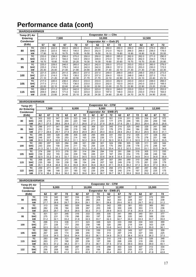
38ARD024/40RM028 Temp (F) Air
Entering Condenser
(Edb)
Evaporator Air — Cfm 7,500 10,000 12,500
Evaporator Air — Ewb (F) 57 62 67 72 57 62 67 72 57 62 67 72
80 TC
SHC kW
236.0 236.0 17.90
242.0 223.0 18.10
260.0 185.0 18.70
280.0 146.0 19.50
254.0 254.0 18.50
254.0 252.0 18.50
269.0 212.0 19.10
290.0 162.0 19.80
266.0 266.0 18.90
266.0 266.0 18.90
276.0 236.0 19.30
296.0 178.0 20.00
85 TC
SHC kW
233.0 233.0 18.70
238.0 221.0 18.80
256.0 184.0 19.50
275.0 144.0 20.20
250.0 250.0 19.30
250.0 249.0 19.30
265.0 210.0 19.80
285.0 161.0 20.60
262.0 262.0 19.70
262.0 262.0 19.70
271.0 234.0 20.00
290.0 176.0 20.80
95 TC
SHC kW
225.0 225.0 20.30
229.0 216.0 20.40
246.0 179.0 21.00
265.0 140.0 21.80
242.0 242.0 20.90
242.0 242.0 20.90
255.0 206.0 21.40
273.0 157.0 22.10
253.0 253.0 21.30
253.0 253.0 21.30
260.0 230.0 21.60
279.0 172.0 22.30
100 TC
SHC kW
221.0 221.0 21.10
225.0 214.0 21.20
241.0 178.0 21.80
260.0 138.0 22.50
237.0 237.0 21.70
237.0 237.0 21.70
249.0 204.0 22.10
268.0 155.0 22.90
248.0 248.0 22.10
248.0 248.0 22.10
255.0 227.0 22.40
273.0 170.0 23.10
105 TC
SHC kW
217.0 217.0 22.00
220.0 211.0 22.10
236.0 175.0 22.60
254.0 136.0 23.40
233.0 233.0 22.50
233.0 233.0 22.50
243.0 202.0 23.00
262.0 153.0 23.70
243.0 243.0 22.90
243.0 243.0 22.90
249.0 225.0 23.20
266.0 168.0 23.90
115 TC
SHC kW
209.0 209.0 23.80
211.0 206.0 23.80
225.0 171.0 24.40
242.0 132.0 25.10
223.0 223.0 24.30
223.0 223.0 24.30
232.0 197.0 24.60
249.0 148.0 25.40
233.0 233.0 24.70
233.0 233.0 24.70
237.0 219.0 24.90
253.0 164.0 25.60
38ARD028/40RM028
Temp (F) Air Entering Condenser
(Edb)
Evaporator Air - CFM 7,500 8,000 9,000 10,000 12,500
Evaporator Air - EWB (F) 62 67 72 62 67 72 62 67 72 62 67 72 62 67 72
80 TC
SHC kW
302 256 26.7
322 213 27.5
347 166 28.6
305 264 26.9
323 220 27.7
348 169 28.8
311 271 27.2
327 233 27.9
351 177 28.9
318 279 27.6
331 246 28.1
355 185 29.0
334 293 28.4
347 259 28.9
372 195 29.8
85 TC
SHC kW
296 253 27.7
317 211 28.6
341 164 29.7
299 260 27.9
318 219 28.8
342 168 29.9
306 267 28.3
321 231 29.0
345 176 30.0
314 275 28.6
325 244 29.2
349 184 30.2
329 289 29.5
341 256 30.0
366 193 31.1
95 TC
SHC kW
285 248 30.0
304 207 30.9
328 159 32.0
288 253 30.2
305 214 31.1
328 163 32.2
295 259 30.6
309 226 31.2
331 171 32.3
302 265 30.9
312 239 31.3
335 179 32.5
317 278 31.9
328 251 32.2
352 188 33.5
100 TC
SHC kW
280 243 31.3
297 204 32.1
320 158 33.1
284 249 31.5
298 211 32.2
321 162 33.2
290 254 31.8
301 224 32.3
324 170 33.4
296 260 32.2
305 236 32.5
328 178 33.6
311 273 33.1
320 248 33.5
344 187 34.6
105 TC
SHC kW
274 239 32.5
290 202 33.2
313 155 34.3
278 244 32.7
291 209 33.4
314 159 34.5
284 249 33.0
294 221 33.6
316 167 34.6
291 255 33.4
298 234 33.8
319 175 34.8
305 268 34.4
313 246 34.8
335 184 35.9
115 TC
SHC kW
268 235 35.1
283 189 35.8
304 150 36.8
272 239 35.3
284 196 35.9
304 154 36.9
278 244 35.6
287 207 36.0
307 162 37.1
284 249 35.9
289 218 36.2
310 170 37.3
298 261 36.9
304 229 37.3
325 179 38.4
122 TC
SHC kW
259 229 37.8
271 186 38.4
291 148 39.4
263 231 38.2
272 190 38.5
291 152 39.6
268 235 38.4
275 204 38.7
294 159 39.7
273 240 38.7
278 214 38.9
297 167 39.8
287 252 39.9
292 225 40.0
311 175 41.0
38ARD028/40RM034
Temp (F) Air Entering
Condenser (Edb)
Evaporator Air - CFM 9,000 10,000 12,000 15,000
Evaporator Air - EWB (F) 62 67 72 62 67 72 62 67 72 62 67 72
80 TC
SHC kW
319 286 27.7
340 238 28.6
367 185 29.7
334 313 28.4
351 269 29.1
376 204 30.1
347 342 28.8
361 303 29.4
387 228 30.3
357 357 29.7
372 316 30.2
399 238 31.2
85 TC
SHC kW
313 282 28.8
335 236 29.7
360 184 30.8
329 309 29.5
344 267 30.2
370 203 31.3
342 338 29.9
355 300 30.5
381 226 31.6
353 353 30.8
365 313 31.4
393 236 32.5
95 TC
SHC kW
301 275 31.2
321 231 32.1
346 178 33.2
316 298 31.8
333 263 32.5
355 197 33.7
330 326 32.3
341 294 32.7
366 220 34.0
340 340 33.3
351 306 33.7
377 230 35.0
100 TC
SHC kW
296 271 32.5
314 228 33.3
338 177 34.4
311 293 33.1
323 258 33.7
348 196 34.8
324 320 33.6
333 290 34.0
358 219 35.1
334 334 34.6
343 303 35.0
369 228 36.1
105 TC
SHC kW
290 267 33.8
306 225 34.5
331 174 35.6
305 288 34.4
316 255 35.0
339 193 36.1
318 313 34.9
325 287 35.3
349 216 36.4
327 327 35.9
335 300 36.3
359 225 37.5
115 TC
SHC kW
283 263 36.5
299 211 37.2
321 168 38.2
298 281 37.1
307 239 37.6
329 187 38.7
310 306 37.5
316 268 37.8
338 209 39.0
319 319 38.6
326 280 39.0
348 218 40.1
122 TC
SHC kW
273 256 39.3
287 208 39.9
308 165 41.0
287 271 40.0
295 235 40.3
315 184 41.3
298 294 40.4
303 263 40.6
324 205 41.5
307 307 41.6
312 275 41.8
334 214 42.8
Performance data (cont)
17

UNIT SIZE 38AR
NOMINAL VOLTAGE V-Ph-Hz
VOLTAGE RANGE* COMPRESSOR 1 COMPRESSOR 2 FAN MOTORS
(Qty 2) POWER SUPPLY
MIN MAX RLA LRA RLA LRA FLA (ea)
LRA (ea) MCA MOCP
Z007
208/230-3-60 187 254 22.4 170 -- -- 0.9 1.6 29.125 51.3 460-3-60 418 506 9.51 80 -- -- 0.5 0.9 12.5 20 380-3-60 342 418 9.51 80 -- -- 0.9 1.6 13 20 400-3-50 360 440 9.43 80 -- -- 0.5 0.9 12.4 20
Z008
208/230-3-60 187 254 25.6 190 -- -- 1.5 3.1 33.9 55 460-3-60 418 506 13.5 95 -- -- 0.8 1.6 17.9 30 380-3-60 342 418 16 135 -- -- 1.5 3.1 21.9 30 400-3-50 360 440 13.5 95 -- -- 0.8 1.6 17.9 30
Z012
208/230-3-60 187 254 35.7 237 -- -- 1.5 3.1 46.5 80 460-3-60 418 506 20.7 130 -- -- 0.8 1.6 26.9 45 380-3-60 342 418 21.4 160 -- -- 1.5 3.1 28.6 45 400-3-50 360 440 20.7 130 -- -- 0.8 1.6 26.9 45
D014
208/230-3-60 187 254 22.4 170 22.4 170 3.6 7.5 65 70 460-3-60 418 506 9.51 80 9.51 80 1.9 -- 28.5 35 380-3-60 342 418 9.51 80 9.51 80 3.6 7.5 32.8 35 400-3-50 360 440 9.43 80 9.43 80 1.7 -- 27.8 30
D016
208/230-3-60 187 254 25.6 190 25.6 190 3.6 7.5 73 80 460-3-60 418 506 13.5 95 13.5 95 1.9 -- 38.5 45 380-3-60 342 418 16 135 16 135 3.6 7.5 49 55 400-3-50 360 440 13.5 95 13.5 95 1.7 -- 38 45
D024
208/230-3-60 187 254 35.7 237 35.7 237 3.6 7.5 98.3 125 460-3-60 418 506 20.7 130 20.7 130 1.9 -- 56.5 70 380-3-60 342 418 21.4 160 21.4 160 3.6 -- 62 70 400-3-50 360 440 20.7 130 20.7 130 1.7 7.5 56 70
D028 208/230-3-60 187 254 45.7 255 45.7 255 5.5 - 125.3 150
460-3-60 418 506 22.9 145 22.9 145 2.8 - 62.9 80 380-3-60 342 418 27.1 155 27.1 155 3.9 - 75.6 90
LEGEND FLA — Full Load Amps kW — Total Fan Motor Input (kilowatts) LRA — Locked Rotor Amps MCA — Minimum Circuit Amps per NEC, Section 430-24
MOCP — Maximum Overcurrent Protection (amps) RLA — Rated Load Amps (compressor) *Units are suitable for use on electrical systems where voltage supplied to the unit terminals is not below or above the listed limits.
NOTES: 1. The MCA and MOCP values are calculated in accordance with theNational Electrical Code (NEC), Article 440. 2. Motor RLA and LRA values are established in accordance with Underwriters’ Laboratories (UL), Standard 1995.
18
Electrical data

Maximum Outdoor Temperature
115 F
Minimum Outdoor Ambient See Minimum Outdoor-Air Operating Temperature
table below. Minimum Return-Air
Temperature 55 F
Maximum Return-Air Temperature 95 F
Normal Acceptable Saturation Suction Temperature Range 25 to 55 F
Maximum Discharge Temperature 295 F
Minimum Discharge Superheat 60 F
UNIT 38AR
MAX ALLOW. LIFT (ft)
LIQUID LINE Max Allow. Pressure Drop (psi)
Max Allow. Temp Loss
(°F) 38ARZ007-012 38ARD014-028 60 7 2
UNIT 38AR
LINEAR LENGTH OF PIPING — FT 0-25 25-50 50-75 75-100
Line Size (in. OD) L S L S L S L S
Z007 3/8 11/8 3/8 11/8 3/8 11/8 3/8 11/8 Z008 3/8 11/8 1/2 11/8 1/2 11/8 1/2 13/8 Z012 1/2 13/8 1/2 13/8 1/2 13/8 1/2 13/8 D014 1/2 1 1/8 1/2 1 1/8 1/2 1 1/8 1/2 1 1/8 D016 1/2 13/8 1/2 13/8 1/2 13/8 5/8 13/8 D024 1/2 13/8 1/2 13/8 5/8 13/8 5/8 3/8
UNIT 38AR
LINEAR LENGTH OF PIPING — M (FT) 0–4 (0-13.1 ) 4-10 (13.1-32.8 ) 10-22 (32.8-72.2) 22–30.5(72.2-100)
Line Size (in. OD) L S L S L S L S
D028 5 /8 1 3 /8 5/8 13/8 7/8 15/8 7/8 15/8
UNIT 38AR
COND TEMP
(F)
MINIMUM OUTDOOR TEMP (F)
Std
38ARZ007-012 38ARD014-024 90 50
38ARD028 90 59
Application data
Operating limits LIQUID LINE DATA — 38ARD014-024 UNITS
Refrigerant piping IMPORTANT: Do not bury refrigerant piping underground.
NOTES: 1. Select air handler at no less than 300 cfm/ton (nominal condensing unit capacity). 2. Total combined draw of the field-supplied liquid line solenoid valve and air handler fan contactor must not exceed 22 va. If the specified va must be exceeded, use a remote relay to control the load.
Liquid line For applications with liquid lift greater than 20 ft, use 1/2-in. liquid line where 3/8 in. is shown; use 5/8- in. liquid line where 1/2 in. is shown. The maximum liquid lift is 60 ft.
MAXIMUM REFRIGERANT CHARGE
It is recommended that the refrigerant piping for all commercial split systems include a liquid line solenoid valve, a liquid line filter drier and a sight glass. For refrigerant lines longer than 75 lineal ft, a liquid line solenoid valve installed at the indoor unit and a suction accumulator are required. Refer to the Refrigerant Specialties Part Numbers table. REFRIGERANT PIPING SIZES
UNIT 38AR R-22 (lb) Z007 17.3 Z008 34.2 Z012 34.2 D014 (2)17.3 D016 (2)34.2 D024 (2)34.2 D028 (2)27.5
MINIMUM OUTDOOR-AIR OPERATING TEMPERATURE
LEGEND L — Liquid Line S — Suction Line NOTES: 1. Pipe sizes are based on a 2° F loss for liquid and suction lines. 2. Pipe sizes are based on the maximum linear length, shown for each column, plus a 50% allowance for fittings. 3. Charge units with R-22 refrigerant in accordance with unit installation instructions. 4. 38ARD has two independent refrigerant circuits and ref pipe sizes for 38ARD series are given for each circuit
REFRIGERANT SPECIALTIES PART NUMBERS
UNIT
LIQUID LINE SIZE
(in.)
LIQUID LINE SOLENOID VALVE
(LLSV)
LLSV COIL
SIGHT GLASS
FILTER DRIER SUCTION LINE
ACCUMULATOR
38ARZ007 3/8 200RB5T4M AMG-24/50-60 AMI1TT3 P502-8304S S-7063S
38ARZ008 3/8 200RB5T4M AMG-24/50-60 AMI1TT3 P502-8304S S-7063S 1/2 200RB5T4M AMG-24/50-60 AMI1TT4 P502-8304S S-7063S
38ARZ012 1/2 200RB6T4M AMG-24/50-60 AMI1TT4 P502-8307S S-7063
38ARD014 1/2 200RB5T4M Qty 2 AMG-24/50-60 Qty 2 AMI1TT4 Qty 2 P502-8304S Qty 2 S-7063S Qty 2
38ARD016 1/2 200RB5T4M Qty 2 AMG-24/50-60 Qty 2 AMI1TT4 Qty 2 P502-8304S Qty 2 S-7063S Qty 2 5/8 200RB5T5M Qty 2 AMG-24/50-60 Qty 2 AMI1TT5 Qty 2 P502-8304S Qty 2 S-7063S Qty 2
38ARD024 1/2 200RB6T4M Qty 2 AMG-24/50-60 Qty 2 AMI1TT5 Qty 2 P502-8307S* Qty 2 S-7063S Qty 2 5/8 200RB6T5M Qty 2 AMG-24/50-60 Qty 2 AMI1TT5 Qty 2 P502-8307S* Qty 2 S-7063S Qty 2
38A RD028 5/8 200RB6T5M Qty 2 AMG-24/50-60 Qty 2 AMI1TT5 Qty 2 P502-8307S* Qty 2 S-7063S Qty 2
19
abdulrehman.zia
Typewritten Text
abdulrehman.zia
Typewritten Text
abdulrehman.zia
Typewritten Text
abdulrehman.zia
Typewritten Text
abdulrehman.zia
Typewritten Text
abdulrehman.zia
Typewritten Text
13/8
abdulrehman.zia
Typewritten Text
abdulrehman.zia
Typewritten Text
abdulrehman.zia
Typewritten Text
7/8
abdulrehman.zia
Typewritten Text
15/8
abdulrehman.zia
Typewritten Text
abdulrehman.zia
Typewritten Text
7/8
abdulrehman.zia
Typewritten Text
abdulrehman.zia
Typewritten Text
abdulrehman.zia
Typewritten Text
15/8
abdulrehman.zia
Typewritten Text

20
Typical wiring schematic38ARZ 230V/460V

21
Typical wiring schematic38ARZ 380V

22
Typical wiring schematic 38ARD 230V/460V- (14-24)

23
Typical wiring schematic 38ARD 380V - (14-24)

24
Typical wiring schematic 38ARD (14-24)

Typical wiring schematic 38ARD028
25
230V,380V, 460V

Typical wiring schematic 38ARD028 230V,380V, 460V (cont.)
26

27
Model number nomenclature - 40RM 4 0 R M - 016 SD B 5 0 1 E D
40RM. Commercial Packaged Air Handler
Cooling Coil - Direct Expansion
Nominal Capacity Tons (kW) 007 6 (21) 016 15 (52) 008 7-1/2 (26) 024 20 (70)
028 25 (87) 012 10 (35) 034 30 (105) 014 12-1/2 (43)
S: SAMCO D: Double Skin
Expansion Device B Thermostatic Expansion Valves (40RM )
Voltage Designation (V-Ph-Hz)
3 208/230-1-60 (007-010 sizes only) 5 208/230-3-60 6 208/230/460-3-60 (all sizes 007-014; size 016
except YC and WD options)460-3-60 (sizes 016 with YC or WD options andall size 024-034 units)
8 230-3-50 9 400-3-50
Revision Number 0 Original Model
Factory-Installed Options
ED
FD
Painted, Standard Motor and Standard Drive
Painted, Standard Motor and Medium-Static Drive (Not available for 028 size for 60 Hz units.
RD
WD
Painted, Alternate Motor and Medium-Static Drive (Available for 60 Hz sizes 028 only
Painted, Alternate Motor and High-Static Drive
Packaging 1 Standard Domestic 3 Export
RD and WD option codes for all 034 size units and 008, 010 units with 208/230-1-60 power designate standard motor and high-static drive.
NOTE: See the following table for the sizes available for each unit.
Quality Assurance
40RM007-034 6-25 Nominal Tons – 60 Hz

28
Physical data
40RM - ENGLISH
UNIT 40RM 007SD 008SD 012SD 014SD 016SD 024SD 028SD 034SD NOMINAL CAPACITY (Tons) 121/271/26 10 15 20 25 30OPERATING WEIGHT (lb)
Base Unit (Double skin) with TXV 448 452 472 804 819 824 1188 1198Plenum 97 97 97 140 140 140 180 180
FANS Qty...Diam. (in.) 1...15 1...15 1...15 2...15 2...15 2...15 2...18 2...18Nominal Airflow (cfm) 2400 3000 4000 5000 6000 8000 10,000 12,000 Airflow Range (cfm) 1800-3000 2250-3750 3000-5000 3750-6250 4500-7500 6000-10,000 7500-12,500 9000-15,000 Nominal Motor Hp (Standard Motor)*
208/230-1-60 1.3 2.4 - - - - - -208/230-3-60 and 460-3-60 2.4 2.4 2.4 2.9 3.7 5.0 7.5 10.0 575-3-60 1.0 2.0 2.0 3.0 3.0 5.0 7.5 10.0 230-3-50, 400-3-50 2.4 2.4 2.9 2.9 2.9 5.0 7.5 10.0
Motor Speed (rpm) 208/230-1-60 1725 1725 - - - - - -208/230-3-60 and 460-3-60 1725 1725 1725 1725 1725 1745 1745 1745575-3-60 1725 1725 1725 1725 1725 1745 1755 1755230-3-50, 400-3-50 1425
REFRIGERANT R-22Operating charge (lb) 3.0 3.0 1.5/1.5 2.0/2.0 2.5/2.5 3.5/3.5 4.5/4.5 5.0/5.0(approx per circuit)²
DIRECT-EXPANSION COIL Enhanced Copper Tubes, Aluminum Sine-Wave Fins Max Working Pressure (psig) 435Face Area (sq ft) 6.67 8.33 10.0 13.25 17.67 19.88 24.86 29.83 No. of Splits 1 1 2 2 2 2 2 2Split Type...Percentage - - Face...50/50 No. of Circuits per Split 12 15 9 9 12 13 15 18Rows...Fins/in. 3...15 3...15 3...17 3...15 3...15 3...17 3...15 3...15
STEAM COIL** Max Working Pressure (psig at 400 F) 175Total Face Area (sq ft) 6.67 6.67 6.67 13.33 13.33 13.33 15.0 15.0 Rows...Fins/in. 1...9 1...9 1...9 1...10 1...10 1...10 1...10 1...10
HOT WATER COIL** Max Working Pressure (psig) 150Total Face Area (sq ft) 6.67 6.67 6.67 13.33 13.33 13.33 15.0 15.0 Rows...Fins/in. 2...8.5 2...8.5 2...8.5 2...8.5 2...8.5 2...8.5 2...12.5 2...12.5Water Volume
(gal) 8.3 13.9 14.3 (ft3) 1.1 1.85 1.90
PIPING CONNECTIONS Quantity...Size (in.)
DX Coil - Suction (ODF) 1...11/8 1...11/8 2...11/8 2...11/8 2...11/8 2...11/8 2...13/8 2...13/8
DX Coil - Liquid Refrigerant (ODF) 1...5/8 2...5/8
Steam Coil, In (MPT) 1...21/2 1...21/2
Steam Coil, Out (MPT) 1...11/2 1...11/2
Hot Water Coil, In (MPT) 1...11/2 1...11/2 1...2Hot Water Coil, Out (MPT) 1...11/2 1...11/2 1...2Condensate (PVC) 1...11/4 ODM/1 IDF
FILTERS Washable - Factory Supplied 4...16 x 20 x 1 4...20 x 24 x 1Quantity...Size (in.) 4...16 x 24 x 1 4...16 x 24 x 1 4...20 x 25 x 1
Access Location Front
LEGEND DX - Direct Expansion TXV - Thermostatic Expansion Valve
*Refer to alternate Fan Motor Data table, pages 54 and 55, for alternate motor data. ²Units are shipped without refrigerant charge. **Please contact your local Carrier sales office for availability. Please contact your local Carrier sales office for the weights of single skin units.

29
Options and accessories Factory-installed optionsAlternate fan motors and drives are availableto provide the widest possiblerange of performance.
Field-installed accessoriesTwo-row hot water coils have copper tubes mechanically bonded to aluminum plate fins and non-ferrousheaders.One-row steam coil has copper tubesand aluminum fins.The Inner Distributing Tube (IDT) designprovides uniformtemperaturesacrossthecoil face.The steamcoil hasa broadoperating pressurerange; up to 175 psig (1207 kPag) at400 F (204.4 C) and up to 300 psig (2069 kPag)at 300 F(148.9 C). The IDT steamcoils are especiallysuited to applications where sub-freezingair enters the unit. Electric resistance heat coils have an open-wire design and are mounted in a rigid frame. Safety cutouts for high temperature conditions are standard. Terminal block for single-point power connection is included. Economizer (enthalpy contr olled) provides ventilation air and ``free'' cooling if outside ambient temperature and humidity are suitable.Can also be usedwith CO2 sensors to help meet indoor air quality requirements. Discharge plenum directs the air discharge directly into the occupied space; integral horizontal and vertical louvers enable redirection of airflow. Accessory is available unpainted or painted. Field assemblyrequired.
Standard units available from the factory are in Double skin.
Return-air grille provides a protective barrier over the return-air opening and givesa finishedappearanceto units installed in the occupied space. Accessoryis availableunpainted or painted. Subbase provides a stable, raised platform and room for condensatedrain trap connection for verticalfloor-mounted units. Accessoryis availableunpainted or painted. Over head suspension package includes necessarybrackets to support units in horizontal ceiling installations. CO2 sensors can be used in conjunction with the economizer accessoryto help meet indoor air quality requirements. The sensor signals the economizer to open when the CO2 level in the spaceexceedsthe set point. A Carrier Comfort Systemprogrammable thermostat can be usedto override the sensorif the outsideair temperatureis too high or too low. Carrier's line of ther mostats provide both programmable and non-programmable capability with the new Debonair line of commercial programmable thermostats, the TEMP System controls offer communication capability with stagedheatingandcooling, the Commercial Electronic thermostats provide 7-day programmablecapability for economicalapplications,while the Non-Programmable thermostatsoffer a multitude of stagedheating and cooling subbaseoptions. Condensate drain trap includesan overflow shutoff switch that can be wired to turn off the unit if the trap becomes plugged. Kit also includesa wire harnessthat can be connected to an alarm if desired. The transparent trap is designed for easyserviceand maintenance.

30
CARRIER THERMOSTATS DEBONAIR COMMERCIAL PROGRAMMABLE
THERMOSTAT
AUTO
Pm COOL
HEAT
®
TEMP SYSTEM THERMOSTAT
COMMERCIAL ELECTRONIC THERMOSTAT
NON-PROGRAMMABLE THERMOSTAT
H C

31
Options and accessories (cont)
40RM WITH DISCHARGE PLENUM, RETURN-AIR GRILLE AND SUBBASE
DISCHARGE PLENUM
RETURN-AIR GRILLE
SUBBASE FAN COIL UNIT
40RM WITH ECONOMIZER
ECONOMIZER
40RM WITH HOT WATER OR STEAM COIL
FAN COIL UNIT
HOT WATER OR STEAM COIL
40RM WITH CONDENSATE TRAP

32
Dimensions 40RM007SD-012SD
UNIT WEIGHT UNIT lb (kg) 40RM007SD 448 (203) 40RM008SD 452 (205) 40RM012SD 472 (214)
TXV - Thermostatic Expansion Valve
NOTES: 1. Dimensions in [ ] are in
millimeters.
2. Direction of air¯ow.
3. Recommended clearance: · Rear: 39(76.2 mm) (28-69[762 mm]
with electric heat accessory) · Front: 28-69(762 mm) · Right side: 28-69(762 mm) · Left Side: 28-69(762 mm) · Local codes or jurisdiction may
prevail. 4. Liquid piping not supplied by
Carrier. 5. Duct flange is factory supplied and
field installed.
All the above mentioned weights are for double skin units.

33
Dimensions (cont) 40RM014SD-024SD
UNIT UNITWEIGHT lb (kg)
40RM014SD 804 (364) 40RM016SD 819 (371) 40RM024SD 824 (373)
TXV - Thermostatic Expansion Valve
NOTES: 1. Dimensions in [ ] are in
millimeters.
2. Direction of airflow.
3. Recommended clearance: · Rear: 39 (76.2 mm) (28-69
[762 mm] with electric heat accessory)
· Front: 28-69(762 mm) · Right side: 28-69(762 mm) · Left Side: 28-69(762 mm) · Local codes or jurisdiction may
prevail. 4. Liquid piping not supplied by
Carrier. 5. Duct flange is factory supplied
and field installed.
All the weights mentioned in the table are for double skin units.
UNIT

34
40RM028SD,034SD
TXV - Thermostatic Expansion Valve
NOTES: 1. Dimensions in [ ] are in
millimeters.
2. Direction of airflow.
3. Recommended clearance: · Rear: 39(76.2 mm) · Front: 28-69(762 mm) · Right side: 28-69(762 mm) · Left Side: 28-69(762 mm) · Local codes or jurisdiction may
prevail. 4. Liquid piping not supplied by
Carrier. 5. Duct flange is factory supplied
and field installed.
UNIT WEIGHT UNIT lb (kg) 40RM028SD 1188 (538) 40RM034SD 1198 (542)
All the above mentioned weights are for double skin units.
Dimensions (cont)

35
OVERHEAD SUSPENSION ACCESSORY
UNIT SIZES 007-012
UNIT SIZES 014-024
UNIT SIZES 028,034
NOTE: Dimensions in [ ] are millimeters.
Dimensions (cont)

36
PLENUM, RETURN-AIR GRILLE, AND SUBBASE ACCESSORIES
UNIT SIZES 007-012
UNIT SIZES 014-024
NOTE: Dimensions in [ ] are millimeters.

37
PLENUM, RETURN-AIR GRILLE, AND SUBBASE ACCESSORIES (cont) UNIT SIZES 028,034
NOTE: Dimensions in [ ] are millimeters.
Dimensions (cont)

38
HOT WATER AND STEAM COIL ACCESSORIES
UNIT SIZES 007-012
NOTE: Dimensions in [ ] are millimeters.
DIMENSION HOT WATER COIL STEAM COIL
A 11⁄2� MPT [38.1] 11⁄2� MPT [38.1] B 11⁄2� MPT [38.1] 21⁄2� MPT [63.5] C 23⁄8� [60.3] 31⁄8� [79.4] D 47⁄8� [123.8] 31⁄8� [79.4] E 21⁄8� [54.0] 49⁄16� [115.8] F 1�-111⁄4� [590.6] 1�-9� [584.2] G 3�- 4� [1016.0] 3�-4� [1016.0]
UNIT SIZES 014-024
NOTE : Dimensions in [ ] are millimeters.
DIMENSION HOT WATER COIL STEAM COIL
A 2� MPT [50.8] 11⁄2� MPT [38.1] B 2� MPT [50.8] 21⁄2� MPT [63.5] C 23⁄8� [60.3] 31⁄8� [79.4] D 47⁄8� [123.8] 31⁄8� [79.4] E 21⁄8� [54.0] 49⁄16� [115.8] F 1�-111⁄4� [590.6] 1�-9� [584.2] G 6�- 8� [2032.0] 6�-8� [2032.0]

39
40RM028SD,034SD
TXV - Thermostatic Expansion Valve
NOTES: 1. Dimensions in [ ] are in
millimeters.
2. Direction of airflow.
3. Recommended clearance: · Rear: 39(76.2 mm) · Front: 28-69(762 mm) · Right side: 28-69(762 mm) · Left Side: 28-69(762 mm) · Local codes or jurisdiction may
prevail. 4. Liquid piping not supplied by
Carrier. 5. Duct flange is factory supplied
and field installed.
UNIT WEIGHT UNIT lb (kg) 40RM028SD 1188 (538) 40RM034SD 1198 (542)
All the above mentioned weights are for double skin units.

40
ECONOMIZER ACCESSORY
UNIT SIZES 007-012
UNIT SIZES 014-024
UNIT SIZES 028,034
NOTES: 1. For horizontal unit applications, economizer can be attached to end of unit opposite duct connections. 2. Dimensions in [ ] are millimeters.

41
Dimensions (cont)ELECTRIC HEAT ACCESSORY
UNIT SIZES 007-012
UNIT SIZES 014-034
UNIT SIZE A B C D E F G H J
014-024 1�-31⁄4� [387.4]
4�-63⁄8� [1381.1]
25⁄16� [58.7]
2�-11⁄4� [641.4]
105⁄8� [269.9]
1�-4� [406.4]
1�-45⁄16� [414.3]
1�-63⁄4� [476.3]
1�-7⁄8� [327.0]
028,034 1�-33⁄8� [390.5]
5�-47⁄16� [1636.8]
21⁄16� [26.9]
2�-63⁄16� [766.8]
1�-1⁄4� [311.2]
1�-7� [482.6]
1�-45⁄16� [414.0]
1�-10� [558.8]
1�-47⁄16� [417.1]
NOTE: Dimensions in [ ] are millimeters.

42
Selection procedure (with example)— English (60 Hz) Cooling (DX) I Determine the cooling load and temperature and quantity of air entering the evaporator. Given: Total Capacity . . . . . . . . . . . . . . . . . . . . 200,000 Btuh
Sensible Heat Capacity . . . . . . . . . . . . . 130,000 Btuh
Air Temperature Entering Indoor Coil . . . . . . . . . . . . . . . . . . . . . . . . 80 F db, 67 F wb
Air Quantity Entering Indoor Coil . . . . . . . 6000 cfm
Ductwork Static Pressure Loss . . . . . . . . . . 0.8 in. wg
Power Supply . . . . . . . . . . . . . . . . . . . . . . . . . 230-3-60
II Determine unit selection and coil refrigerant temperature. Enter the Cooling Capacities table at 6000 cfm. Select a 40RM016 unit which has a total capacity of 207,000 and 174,000 Btuh at 40 and 45 F coil refrigerant temperature, respectively. By interpolation, coil refrigerant temperature of 41.1 F is needed to give a total capacity of 200,000 Btuh. Sensible capacity is approximately 149,000 Btuh. Cooling load is satisfied.
Fan I Determine fan speed and brake horsepower: From the Accessory Pressure Drop table, read a loss of 0.23 in. wg for a hot water coil at 6000 cfm. External static pressure = 0.80 + 0.23
= 1.03 in. wg
Enter 40RM016 Fan Performance table at 6000 cfm and 1.03 in. wg. Interpolate and determine fan speed of 866 rpm and 2.7 bhp.
II Determine motor and drive. Enter the fan motor data tables on page 54, and find that the 230 v standard motor for a 40RM016 unit is rated at 3.7 Hp. Since the bhp required is 2.7, a standard motor satisfies the requirement and should be used. Next, find the type of drive that satisfies the 866 rpm requirement in the Drive Data tables on pages 59,60 . For a 40RM016 unit, the Medium-Static Drive table on page 59 shows an rpm range of 742 to 943. Since the rpm required is 866, the medium-static drive satisfies the requirement and should be used. Select the standard motor and medium-static drive combination (option code HC or FD). To select an outdoor unit for this 40RM016 indoor section, refer to the Combination Rating sheets for Carrier condensing units in the condensing unit Product Data Digest, or consult the Carrier Electronic Catalog.

43
Performance data (cont) FAN PERFORMANCE DATA — 0.0-1.2 in. wg ESP — 60 Hz, ENGLISH
UNIT AIRFLOW (Cfm)
EXTERNAL STATIC PRESSURE (in. wg) 0.0 0.2 0.4 0.6 0.8 1.0 1.2
Rpm Bhp Rpm Bhp Rpm Bhp Rpm Bhp Rpm Bhp Rpm Bhp Rpm Bhp
40RM 007
1,800 2,100 2,400 2,700 3,000
320 373 427 480 533
0.22 0.31 0.42 0.54 0.69
442 483 526 570 616
0.32 0.42 0.53 0.67 0.82
534 569 606 646 687
0.42 0.53 0.64 0.78 0.94
611 642 676 712 750
0.52 0.63 0.75 0.89 1.05
678 708 739 773 808
0.61 0.73 0.86 1.00 1.16
739 767 796 828 862
0.70 0.82 0.96 1.11 1.28
795 821 849 880 912
0.80 0.92 1.06 1.21 1.39
40RM 008
2,250 2,600 3,000 3,400 3,750
359 415 478 542 598
0.32 0.45 0.62 0.82 1.03
472 516 569 624 673
0.44 0.57 0.75 0.95 1.17
560 599 645 695 740
0.55 0.68 0.86 1.08 1.29
634 669 712 758 800
0.65 0.79 0.98 1.20 1.42
700 732 773 815 855
0.75 0.90 1.09 1.31 1.60
759 790 828 869 906
0.86 1.01 1.20 1.43 1.66
814 843 879 918 954
0.96 1.11 1.32 1.55 1.78
40RM 012
3,000 3,500 4,000 4,500 5,000
444 518 592 666 740
0.58 0.82 1.11 1.44 1.83
541 604 669 735 803
0.71 0.95 1.25 1.59 1.98
621 677 736 797 861
0.83 1.08 1.38 1.72 2.12
691 742 797 854 914
0.94 1.20 1.51 1.86 2.26
753 801 853 907 964
1.05 1.32 1.63 1.99 2.39
809 855 904 956
1010
1.17 1.44 1.75 2.12 2.53
862 906 953
1003 1055
1.28 1.56 1.88 2.24 2.66
40RM 014
3,750 4,300 5,000 5,700 6,250
363 416 484 552 605
0.37 0.53 0.81 1.17 1.51
475 517 573 631 678
0.58 0.78 1.08 1.47 1.83
566 601 650 702 744
0.80 1.02 1.35 1.76 2.15
645 676 719 766 805
1.02 1.26 1.62 2.06 2.47
715 743 782 826 862
1.24 1.50 1.89 2.36 2.79
779 805 841 881 915
1.47 1.74 2.16 2.66 3.11
839 862 896 934 966
1.69 1.99 2.44 2.96 3.43
40RM 016
4,500 5,300 6,000 6,800 7,500
391 460 521 590 651
0.51 0.80 1.13 1.60 2.10
495 551 602 663 718
0.75 1.08 1.43 1.93 2.45
581 629 675 730 779
1.00 1.35 1.73 2.26 2.81
657 700 741 791 837
1.25 1.63 2.04 2.59 3.16
725 764 801 847 890
1.50 1.91 2.34 2.92 3.52
787 823 858 901 941
1.76 2.20 2.65 3.26 3.88
845 878 911 951 990
2.02 2.48 2.96 3.60 4.24
40RM 024
6,000 7,000 8,000 9,000
10,000
503 586 670 754 838
1.07 1.64 2.37 3.28 4.39
587 660 735 812 891
1.37 1.98 2.74 3.69 4.83
661 726 795 867 941
1.67 2.31 3.12 4.09 5.27
727 787 851 918 988
1.97 2.65 3.49 4.50 5.70
789 844 904 967
1034
2.28 2.99 3.86 4.90 6.14
846 898 954
1014 1077
2.59 3.33 4.23 5.31 6.85
900 948
1001 1059 1120
2.90 3.67 4.61 5.72 7.02
40RM 028
7,500 8,750
10,000 11,250 12,500
412 481 549 618 687
1.15 1.76 2.55 3.52 4.71
492 550 610 672 735
1.53 2.17 2.99 4.00 5.22
568 616 669 725 783
2.00 2.66 3.50 4.53 5.78
640 680 726 777 830
2.56 3.22 4.07 5.12 6.38
710 742 782 827 876
3.22 3.86 4.70 5.76 7.04
776 802 836 876 922
3.98 4.58 5.40 6.45 7.74
840 860 889 925 966
4.83 5.38 6.17 7.21 8.49
40RM 034
9,000 10,500 12,000 13,500 15,000
471 550 628 707 785
1.78 2.72 3.93 5.44 7.27
539 608 679 752 826
2.17 3.15 4.40 5.94 7.81
604 665 730 797 867
2.63 3.64 4.92 6.49 8.39
667 720 779 841 907
3.17 4.18 5.48 7.08 9.01
728 774 827 885 947
3.78 4.79 6.09 7.71 9.66
788 827 874 928 986
4.46 5.45 6.76 8.38
10.35
845 878 921 970
1024
5.22 6.18 7.47 9.10
11.07
See Legend and Notes on page 4 0 .

44
FAN PERFORMANCE DATA — 1.4-2.4 in. wg ESP — 60 Hz, ENGLISH
UNIT AIRFLOW (Cfm) 1.4
Rpm Bhp 1.6
Rpm Bhp
EXTERNAL STATIC PRESSURE (in. wg) 1.8 2.0 2.2
Rpm Bhp Rpm Bhp Rpm Bhp 2.4
Rpm Bhp
1,800 847 0.89 896 0.98 942 1.07 986 1.16 1027 1.25 — —
40RM 007
2,100 2,400 2,700
872 899 928
1.02 1.16 1.32
920 946 974
1.11 1.26 1.42
965 990
1018
1.21 1.36 1.52
1008 1033 1059
1.30 1.46 1.63
1050 1073 1099
1.40 1.55 1.73
— — —
— — —
3,000 959 1.49 1004 1.60 1046 1.71 1087 1.81 1126 1.92 — —
40RM 008
2,250 2,600 3,000 3,400
865 893 928 965
1.06 1.22 1.43 1.66
913 940 973
1010
1.16 1.33 1.54 1.78
958 984
1017 1052
1.27 1.43 1.65 1.89
1001 1027 1058 1092
1.37 1.54 1.76 2.00
1042 1067 1098 1131
1.47 1.65 1.87 2.12
— — — —
— — — —
3,750 1000 1.90 1043 2.02 1084 2.13 1124 2.25 1162 2.37 — —
3,000 911 1.39 958 1.50 1002 1.61 1044 1.72 1084 1.83 1123 1.94
40RM 012
3,500 4,000 4,500
953 999
1047
1.67 2.00 2.37
998 1042 1089
1.79 2.12 2.50
1041 1084 1129
1.90 2.24 2.62
1082 1124 1168
2.02 2.36 2.74
1122 1162
—
2.13 2.48 —
1159 1199
—
2.25 2.60 —
5,000 1097 2.79 1138 2.92 1177 3.05 — — — — — —
3,750 894 1.91 947 2.14 996 2.37 1044 2.60 1089 2.83 — —
40RM 014
4,300 5,000 5,700
916 948 984
2.23 2.71 3.25
967 997
1031
2.48 2.98 3.55
1016 1044 1076
2.73 3.26 3.86
1062 1089 1120
2.98 3.53 4.16
1107 1133 1162
— 3.24 3.81 4.46
— — — —
— — — —
—
6,250 1014 3.75 1060 4.07 1104 4.39 1147 4.71 1188 5.03 — —
4,500 899 2.29 951 2.56 999 2.84 1046 3.12 1091 3.41 1133 3.70
40RM 016
5,300 6,000 6,800
930 961 999
2.78 3.28 3.94
980 1009 1045
3.08 3.60 4.28
1027 1055 1089
3.38 3.92 4.63
1072 1098 1132
3.68 4.24 4.98
1116 1141 1173
3.99 4.57 5.33
1157 1181
—
4.30 4.91 —
7,500 1036 4.60 1080 4.97 1123 5.34 1164 5.71 — — — —
6,000 950 3.21 999 3.53 1045 3.85 1089 4.17 1131 4.50 1172 4.83
40RM 024
7,000 8,000 9,000
996 1047 1102
4.02 4.99 6.13
1042 1091 1143
4.37 5.37 6.54
1086 1133 1183
4.72 5.75 6.96
1129 1173
—
5.07 6.13 —
1169 — —
5.43 — —
— — —
— — —
10,000 1160 7.46 1200 7.91 — — — — — — — —
7,500 903 5.79 963 6.83 1021 7.98 1078 9.21 — — — —
40RM 028
8,750 10,000 11,250
917 941 972
6.26 7.01 8.02
972 991
1019
7.22 7.91 8.89
1025 1040 1064
8.26 8.89 9.83
1078 1089
—
9.38 9.93 —
— — —
— — —
— — —
— — —
12,500 1010 9.29 1053 10.15 1095 11.05 — — — — — —
9,000 901 6.07 955 6.98 1008 7.98 1060 9.05 — — — —
40RM 034
10,500 12,000 13,500
928 966
1011
6.98 8.24 9.86
978 1011 1052
7.84 9.07
10.67
1026 1055 1092
8.76 9.95
11.52
1073 1098
—
9.74 10.88
—
— — —
— — —
— — —
— — —
15,000 1062 11.84 — — — — — — — — — —
See Legend and Notes on page 40.

45
Performance data (cont)
LEGEND
FACTOR Y-SUPPLIED FILTER PRESSURE DROP
Bhp - Brake Horsepower Input to Fan
- ENGLISH
ESP - External Static Pressure
Bold indicates field supplied drive is required.Plain type indicates standard motor and standard drive.Underline indicates a different motor and drive combination other thanthe standard motor and standard drive combination is required. Refer tofan motor and drive tables, pages 54-60, to complete selection.
NOTES: 1. Maximum allowable fan speed is 1100 rpm for unit sizes 028 and
034; 1200 rpm for all other sizes. 2. Fan performance is based on deductions for wet coil, clean 1-in.
filters, and unit casing. See table at right for factory-supplied filter pressure drop.
3. For 60 Hz units, the medium-static drive and standard motor combination is not available for 028 size.
UNIT AIRFLOW (Cfm)
PRESSURE DROP (in. wg)
40RM 007
1,800 2,400 3,000
0.05 0.08 0.11
40RM 008
2,250 3,000 3,750
0.07 0.11 0.15
40RM 012
3,000 4,000 5,000
0.11 0.17 0.23
40RM 014
3,750 5,000 6,250
0.06 0.10 0.13
40RM 016
4,500 6,000 7,500
0.08 0.12 0.17
40RM 024
6,000 8,000
10,000
0.12 0.19 0.26
40RM 028
7,500 10,000 12,500
0.15 0.22 0.30
40RM 034
9,000 12,000 15,000
0.19 0.29 0.40
ACCESSORY PLENUM AIR THROW DATA — ENGLISH (Ft)
UNIT AIRFLOW (Cfm)
VANE DEFLECTION Straight 211⁄2° 45°
40RM 007 2,400 39 33 24
40RM 008 3,000 45 38 28
40RM 012 4,000 55 46 33
40RM 014
5,000 45 38 28
40RM 016 6,000 50 43 31
40RM 024 8,000 60 51 37
40RM 028 10,000 76 65 47
40RM 034 12,000 85 72 52
NOTE: Throw distances shown are for 75 fpm terminal velocity. Use the following multipliers to determine throw values for other terminal velocities.
TERMINAL VELOCITY (Fpm) THROW FACTOR
50 X 1.50 100 X 0.75 150 X 0.50

46
ACCESSORY PRESSURE DROP — ENGLISH
(in. wg)
UNIT AIRFLOW (Cfm)
DISCHARGE PLENUM
RETURN AIR GRILLE
HEATING COILS ECONOMIZERHot Water Steam Electric
40RM 007
1,800 2,400 3,000
0.06 0.10 0.14
0.01 0.01 0.02
0.10 0.16 0.23
0.10 0.16 0.23
0.04 0.06 0.10
0.05 0.07 0.09
40RM 008
2,250 3,000 3,750
0.09 0.14 0.21
0.01 0.02 0.03
0.15 0.23 0.35
0.15 0.23 0.35
0.06 0.10 0.15
0.06 0.09 0.15
40RM 012
3,000 4,000 5,000
0.14 0.22 0.32
0.02 0.04 0.06
0.23 0.37 0.53
0.23 0.37 0.53
0.10 0.17 0.26
0.09 0.17 0.28
40RM 014
3,750 5,000 6,250
0.07 0.12 0.17
0.01 0.02 0.02
0.11 0.17 0.25
0.11 0.17 0.25
0.04 0.07 0.11
0.05 0.07 0.11
40RM 016
4,500 6,000 7,500
0.10 0.16 0.23
0.01 0.02 0.03
0.15 0.23 0.33
0.15 0.23 0.33
0.06 0.10 0.15
0.06 0.09 0.15
40RM 024
6,000 8,000
10,000
0.16 0.26 0.37
0.02 0.04 0.06
0.23 0.37 0.53
0.23 0.37 0.53
0.10 0.17 0.26
0.09 0.17 0.28
40RM 028
7,500 10,000 12,500
0.15 0.24 0.34
0.02 0.03 0.05
0.28 0.44 0.63
0.28 0.44 0.63
0.09 0.16 0.24
0.06 0.09 0.14
40RM 034
9,000 12,000 15,000
0.20 0.32 0.46
0.03 0.05 0.07
0.37 0.59 0.85
0.37 0.59 0.85
0.13 0.22 0.34
0.08 0.14 0.21

47
Electrical data
STANDARD MOTORS
UNIT V*-PH-Hz VOLTAGE LIMITS
FAN MOTOR POWER SUPPLY
Hp (kW) FLA Minimum
Circuit Amps
MOCP
208/230-1-60 187-253 1.3 (0.97) 7.6 9.5 15
208/230-3-60 187-253 2.4 (1.79) 5.2 6.5 15
40RM 007
460-3-60 414-506 2.4 (1.79) 2.6 3.3 15
575-3-60 518-632 1.0 (0.75) 1.4 8.0 15
230-3-50 207-253 2.4 (1.79) 5.2 6.5 15
400-3-50 360-440 2.4 (1.79) 2.6 3.3 15
208/230-1-60 187-253 2.4 (1.79) 11.0 13.8 20
40RM 008
208/230-3-60 187-253 2.4 (1.79) 5.2 6.5 15
460-3-60 414-506 2.4 (1.79) 2.6 3.3 15
575-3-60 518-632 2.0 (1.49) 2.3 2.9 15
230-3-50 207-253 2.4 (1.79) 5.2 6.5 15
400-3-50 360-440 2.4 (1.79) 2.6 3.3 15
208/230-3-60 187-253 2.4 (1.79) 5.2 6.5 20
40RM 012
460-3-60 414-506 2.4 (1.79) 2.6 3.3 15
575-3-60 518-632 2.0 (1.49) 2.3 2.9 15
230-3-50 207-253 2.9 (2.16) 7.5 9.4 15
400-3-50 360-440 2.9 (2.16) 3.4 4.3 15
208/230-3-60 187-253 2.9 (2.16) 7.5 9.4 15
40RM 460-3-60 414-506 2.9 (2.16) 3.4 4.3 15
014 575-3-60 518-632 3.0 (2.24) 3.8 4.8 15
230-3-50 207-253 2.9 (2.16) 7.5 9.4 15
400-3-50 360-440 2.9 (2.16) 3.4 4.3 15
208/230-3-60 187-253 3.7 (2.76) 10.2 12.8 20
40RM 016
460-3-60 414-506 3.7 (2.76) 4.8 6.0 15
575-3-60 518-632 3.0 (2.24) 3.8 4.8 15
230-3-50 207-253 2.9 (2.16) 7.5 9.4 15
400-3-50 360-440 2.9 (2.16) 3.4 4.3 15
208/230-3-60 187-253 5.0 (3.73) 15.3/12.8 19.1/16.0 30/25
40RM 460-3-60 414-506 5.0 (3.73) 6.4 8.0 15
024 575-3-60 518-632 5.0 (3.73) 5.1 6.4 15
230-3-50 207-253 5.0 (3.73) 15.2 19.0 30
400-3-50 360-440 5.0 (3.73) 7.6 9.5 15
208/230-3-60 187-253 7.5 (5.59) 22.4/19.4 28.0/24.3 50/40
40RM 460-3-60 414-506 7.5 (5.59) 9.7 12.1 20
028 575-3-60 518-632 7.5 (5.59) 7.8 9.8 15
230-3-50 207-253 7.5 (5.59) 22.8 28.5 50
400-3-50 360-440 7.5 (5.59) 11.4 14.3 25
208/230-3-60 187-253 10.0 (7.46) 29.3/26.8 36.6/33.5 60/60
40RM 460-3-60 414-506 10.0 (7.46) 13.4 16.8 30
034 575-3-60 518-632 10.0 (7.46) 10.3 12.9 20
230-3-50 207-253 10.0 (7.46) 32.2 40.3 70
400-3-50 360-440 10.0 (7.46) 16.1 20.1 30
See Legend and Notes on page 43.

48
ALTERNATE MOTORS
UNIT V*-PH-Hz VOLTAGE LIMITS
FAN MOTOR POWER SUPPLY
Hp (kW) FLA Minimum
Circuit Amps
MOCP
208/230-1-60 187-253 2.4 (1.79) 11.0 13.8 20
208/230-3-60 187-253 2.9 (2.16) 7.5 9.4 15
40RM 007
460-3-60 414-506 2.9 (2.16) 3.4 4.3 15
575-3-60 518-632 2.0 (1.49) 2.3 2.9 15
230-3-50 207-253 2.4 (1.79) 5.2 6.5 15
400-3-50 360-440 2.4 (1.79) 2.6 3.3 15
208/230-1-60 187-253 2.4 (1.79) 11.0 13.8 15
40RM 008
208/230-3-60 187-253 2.9 (2.16) 7.5 9.4 15
460-3-60 414-506 2.9 (2.16) 3.4 4.3 15
575-3-60 518-632 3.0 (2.24) 3.8 4.8 15
230-3-50 207-253 2.9 (2.16) 7.5 9.4 15
400-3-50 360-440 2.9 (2.16) 3.4 4.3 15
208/230-3-60 187-253 3.7 (2.76) 10.2 12.8 20
40RM 012
460-3-60 414-506 3.7 (2.76) 4.8 6.0 15
575-3-60 518-632 3.0 (2.24) 3.8 4.8 15
230-3-50 207-253 5.0 (3.73) 15.2 19.0 30
400-3-50 360-440 5.0 (3.73) 7.6 9.5 15
208/230-3-60 187-253 3.7 (2.76) 10.2 12.7 20
40RM 460-3-60 414-506 3.7 (2.76) 4.8 6.0 15
014 575-3-60 518-632 5.0 (3.73) 5.1 6.4 15
230-3-50 207-253 5.0 (3.73) 15.2 19.0 30
400-3-50 360-440 5.0 (3.73) 7.6 9.5 15
208/230-3-60 187-253 5.0 (3.73) 15.3/12.8 19.1/16.0 30/25
40RM 016
460-3-60 414-506 5.0 (3.73) 6.4 8.0 15
575-3-60 518-632 5.0 (3.73) 5.1 6.4 15
230-3-50 207-253 5.0 (3.73) 15.2 19.0 30
400-3-50 360-440 5.0 (3.73) 7.6 9.5 15
208/230-3-60 187-253 7.5 (5.59) 22.4/19.4 28.0/24.3 50/40
40RM 460-3-60 414-506 7.5 (5.59) 9.7 12.1 20
024 575-3-60 518-632 7.5 (5.59) 7.8 9.8 15
230-3-50 207-253 7.5 (5.59) 22.8 28.5 50
400-3-50 360-440 7.5 (5.59) 11.4 14.3 25
208/230-3-60 187-253 10.0 (7.46) 29.3/26.8 36.6/33.5 60/60
40RM 460-3-60 414-506 10.0 (7.46) 13.4 16.8 30
028 575-3-60 518-632 10.0 (7.46) 10.3 12.9 20
230-3-50 207-253 10.0 (7.46) 32.2 40.3 60
400-3-50 360-440 10.0 (7.46) 16.1 20.1 30
LEGEND FLA — Full Load Amps MOCP — Maximum Overcurrent Protection *Motors are designed for satisfactory operation within 10% of nominal voltages shown. Voltages should not exceed the limits shown in the Voltage Limits column.
NOTES: 1. Minimum circuit amps (MCA) and MOCP values are calculated in accordance
with NEC (National Electrical Code) (U.S.A. standard), Article 440. 2. Motor FLA values are established in accordance with UL (Underwriters’ Labo-
ratories) Standard 1995 (U.S.A. standard). 3. Unbalanced 3-Phase Supply Voltage
Never operate a motor where a phase imbalance in supply voltage is greater than 2%. Use the following formula to determine the percentage of voltage imbalance. % Voltage Imbalance
max voltage deviation from average voltage= 100 xaverage voltage
EXAMPLE: Supply voltage is 400-3-50.AB = 393 vBC = 403 vAC = 396 v
393 + 403 + 396 Average Voltage = 3
1192 = 3
= 397
Determine maximum deviation from average voltage. (AB) 397 − 393 = 4 v (BC) 403 − 397 = 6 v (AC) 397 − 396 = 1 v
Maximum deviation is 6 v.
Determine percent voltage imbalance. 6% Voltage Imbalance = 100 x
397
= 1.5%
This amount of phase imbalance is satisfactory because it is below the maxi-mum allowable 2%.
IMPORTANT: If the supply voltage phase imbalance is more than 2%, con-tact your local electric utility company immediately.

49
Electrical data (cont) ELECTRIC HEATER DATA
HEATER PART NO. UNIT V-PH-Hz
FAN MOTOR ELECTRIC HEATER(S)
MCA* MOCP*Nominal Actual Capacity (kW) FLA
Hp kW FLA Capacity (kW) Stage 1 Stage 2 Total
208-3-60
1.3† 2.4† 2.4
0.97 1.79 1.79
7.6 11.0 5.2
5 5 5
3.8 3.8 3.8
— — —
3.8 3.8 3.8
10.4 10.4 10.4
22.5 26.8 19.5
25 35 20
2.9 3.7
2.16 2.76
7.5 10.2
5 5
3.8 3.8
— —
3.8 3.8
10.4 10.4
22.4 25.8
25 30
CAELHEAT001A00 1.3† 2.4†
0.97 1.79
7.6 11.0
5 5
5.0 5.0
— —
5.0 5.0
12.0 12.0
24.5 28.8
25 35
240-3-60 2.4 1.79 5.2 5 5.0 — 5.0 12.0 21.5 25 2.9 2.16 7.5 5 5.0 — 5.0 12.0 24.4 25 3.7 2.76 10.2 5 5.0 — 5.0 12.0 27.8 30
2.4 1.79 5.2 5 5.0 — 5.0 12.0 21.5 25 240-3-50 2.9 2.16 7.5 5 5.0 — 5.0 12.0 24.4 25
5.0 3.73 15.2 5 5.0 — 5.0 12.0 34.0 40
2.4 1.79 2.6 5 5.0 — 5.0 6.00 10.8 15 480-3-60 2.9 2.16 3.4 5 5.0 — 5.0 6.00 11.8 15
CAELHEAT002A00 3.7 2.76 4.8 5 5.0 — 5.0 6.00 13.5 15
2.4 1.79 2.6 5 3.5 — 3.5 5.00 9.5 15 400-3-50 2.9 2.16 3.4 5 3.5 — 3.5 5.00 10.5 15
5.0 3.73 7.6 5 3.5 — 3.5 5.00 15.8 20
1.0 0.75 1.4 5 5.0 — 5.0 5.00 8.0 15 CAELHEAT003A00 575-3-60 2.0 1.49 2.3 5 5.0 — 5.0 5.00 9.2 15
3.0 2.24 3.8 5 5.0 — 5.0 5.00 11.0 15
1.3† 0.97 7.6 10 7.5 — 7.5 20.8 35.6 40
208-3-60 2.4† 2.4 2.9 3.7
1.79 1.79 2.16 2.76
11.0 5.2 7.5
10.2
10 10 10 10
7.5 7.5 7.5 7.5
— — — —
7.5 7.5 7.5 7.5
20.8 20.8 20.8 20.8
39.8 32.6 35.4 38.8
40 35 40 40
CAELHEAT004A00 240-3-60
1.3† 2.4† 2.4 2.9 3.7
0.97 1.79 1.79 2.16 2.76
7.6 11.0 5.2 7.5
10.2
10 10 10 10 10
10.0 10.0 10.0 10.0 10.0
— — — — —
10.0 10.0 10.0 10.0 10.0
24.1 24.1 24.1 24.1 24.1
39.6 43.8 36.6 39.4 42.8
40 50 40 40 50
40RM007-012 240-3-50
2.4 2.9 5.0
1.79 2.16 3.73
5.2 7.5
15.2
10 10 10
10.0 10.0 10.0
— — —
10.0 10.0 10.0
24.1 24.1 24.1
36.6 39.4 49.1
40 40 50
2.4 1.79 2.6 10 10.0 — 10.0 12.0 18.3 20 480-3-60 2.9 2.16 3.4 10 10.0 — 10.0 12.0 19.3 20
CAELHEAT005A00 3.7 2.76 4.8 10 10.0 — 10.0 12.0 21.0 25
2.4 1.79 2.6 10 6.9 — 6.9 10.0 15.8 20 400-3-50 2.9 2.16 3.4 10 6.9 — 6.9 10.0 16.8 20
5.0 3.73 7.6 10 6.9 — 6.9 10.0 22.0 25
1.0 0.75 1.4 10 10.0 — 10.0 10.0 14.3 15 CAELHEAT006A00 575-3-60 2.0 1.49 2.3 10 10.0 — 10.0 10.0 15.4 20
3.0 2.24 3.8 10 10.0 — 10.0 10.0 17.3 20
208-3-60
1.3† 2.4† 2.4 2.9
0.97 1.79 1.79 2.16
7.6 11.0 5.2 7.5
15 15 15 15
11.3 11.3 11.3 11.3
— — — —
11.3 11.3 11.3 11.3
31.3 31.3 31.3 31.3
48.6 52.9 45.6 48.5
50 60 50 50
3.7 2.76 10.2 15 11.3 — 11.3 31.3 51.9 60
CAELHEAT007A00 1.3† 2.4†
0.97 1.79
7.6 11.0
15 15
15.0 15.0
— —
15.0 15.0
36.1 36.1
54.6 58.9
60 60
240-3-60 2.4 1.79 5.2 15 15.0 — 15.0 36.1 51.6 60 2.9 2.16 7.5 15 15.0 — 15.0 36.1 54.5 60 3.7 2.76 10.2 15 15.0 — 15.0 36.1 57.9 60
2.4 1.79 5.2 15 15.0 — 15.0 36.1 51.6 60 240-3-50 2.9 2.16 7.5 15 15.0 — 15.0 36.1 54.5 60
5.0 3.73 15.2 15 15.0 — 15.0 36.1 64.1 70
2.4 1.79 2.6 15 15.0 — 15.0 18.0 25.8 30 480-3-60 2.9 2.16 3.4 15 15.0 — 15.0 18.0 26.8 30
CAELHEAT008A00 3.7 2.76 4.8 15 15.0 — 15.0 18.0 28.6 30
2.4 1.79 2.6 15 10.4 — 10.4 15.0 22.0 25 400-3-50 2.9 2.16 3.4 15 10.4 — 10.4 15.0 23.0 25
5.0 3.73 7.6 15 10.4 — 10.4 15.0 28.3 30
1.0 0.75 1.4 15 15.0 — 15.0 15.1 20.6 25 CAELHEAT009A00 575-3-60 2.0 1.49 2.3 15 15.0 — 15.0 15.1 21.7 25
3.0 2.24 3.8 15 15.0 — 15.0 15.1 23.6 25

50
ELECTRIC HEATER DATA (cont)
HEATER PART NO. UNIT V-PH-Hz
FAN MOTOR ELECTRIC HEATER(S)
MCA* MOCP*Nominal Actual Capacity (kW) FLA
Hp kW FLA Capacity (kW) Stage 1 Stage 2 Total 1.3† 2.4†
0.97 1.79
7.6 11.0
25 25
11.3 11.3
7.5 7.5
18.8 18.8
52.1 52.1
74.7 78.9
80 80
208-3-60 2.4 2.9 3.7
1.79 2.16 2.76
5.2 7.5
10.2
25 25 25
11.3 11.3 11.3
7.5 7.5 7.5
18.8 18.8 18.8
52.1 52.1 52.1
71.7 74.5 77.9
80 80 80
CAELHEAT010A00 1.3† 2.4†
0.97 1.79
7.6 11.0
25 25
15.0 15.0
10.0 10.0
25.0 25.0
60.1 60.1
84.7 88.9
90 90
240-3-60 2.4 2.9 3.7
1.79 2.16 2.76
5.2 7.5
10.2
25 25 25
15.0 15.0 15.0
10.0 10.0 10.0
25.0 25.0 25.0
60.1 60.1 60.1
81.7 84.6 87.9
90 90 90
40RM007-012 240-3-50
2.4 2.9 5.0
1.79 2.16 3.73
5.2 7.5
15.2
25 25 25
15.0 15.0 15.0
10.0 10.0 10.0
25.0 25.0 25.0
60.1 60.1 60.1
81.7 84.6 94.2
90 90
100
2.4 1.79 2.6 25 15.0 10.0 25.0 30.1 40.8 50 480-3-60 2.9 2.16 3.4 25 15.0 10.0 25.0 30.1 41.8 50
CAELHEAT011A00 3.7 2.76 4.8 25 15.0 10.0 25.0 30.1 43.6 50
2.4 1.79 2.6 25 10.4 6.9 17.4 25.1 34.6 25 400-3-50 2.9 2.16 3.4 25 10.4 6.9 17.4 25.1 35.6 40
5.0 3.73 7.6 25 10.4 6.9 17.4 25.1 40.8 50
1.0 0.75 1.4 25 15.0 10.0 25.0 25.1 33.1 35 CAELHEAT012A00 575-3-60 2.0 1.49 2.3 25 15.0 10.0 25.0 25.1 34.3 35
3.0 2.24 3.8 25 15.0 10.0 25.0 25.1 36.1 40
2.4† 1.79 11.0 35 15.0 11.3 26.3 73.0 105.0 110
208-3-60 2.4 2.9
1.79 2.16
5.2 7.5
35 35
15.0 15.0
11.3 11.3
26.3 26.3
73.0 73.0
97.7 100.6
100 110
3.7 2.76 10.2 35 15.0 11.3 26.3 73.0 104.0 110
2.4† 1.79 11.0 35 20.0 15.0 35.0 84.2 119.0 125 CAELHEAT013A00 240-3-60 2.4
2.9 1.79 2.16
5.2 7.5
35 35
20.0 20.0
15.0 15.0
35.0 35.0
84.2 84.2
111.7 114.6
125 125
3.7 2.76 10.2 35 20.0 15.0 35.0 84.2 118.0 125
40RM008,012 240-3-50
2.4 2.9 5.0
1.79 2.16 3.73
5.2 7.5
15.2
35 35 35
20.0 20.0 20.0
15.0 15.0 15.0
35.0 35.0 35.0
84.2 84.2 84.2
111.7 114.6 124.2
125 125 125
2.4 1.79 2.6 35 20.0 15.0 35.0 42.1 55.9 60 480-3-60 2.9 2.16 3.4 35 20.0 15.0 35.0 42.1 56.9 60
CAELHEAT014A00 3.7 2.76 4.8 35 20.0 15.0 35.0 42.1 58.6 60
2.4 1.79 2.6 35 13.9 10.4 24.3 35.1 47.1 50 400-3-50 2.9 2.16 3.4 35 13.9 10.4 24.3 35.1 48.1 50
5.0 3.73 7.6 35 13.9 10.4 24.3 35.1 53.4 60
CAELHEAT015A00 575-3-60 2.0 3.0
1.49 2.24
2.3 3.8
35 35
20.0 20.0
15.0 15.0
35.0 35.0
35.1 35.1
46.8 48.7
50 50
LEGEND
FLA — Full Load Amps Hp — Horsepower MCA — Minimum Circuit Amps MOCP — Maximum Overcurrent Protection (Amps) *Values shown are for single-point connection of electric heat accessory and air handler.
†Single-phase motors. All other motors are 3-phase.
NOTES: 1. Electrical resistance heaters are rated at 240 v, 480 v, or 575 v. To determine
heater capacity (kW) at unit nameplate multiply the 240-v, 480-v, or 575-v ca-pacity (kW) by the factor shown in the table below for the unit voltage.
2. The following equation converts kW of heat energy to Btuh: kW x 3,412 = Btuh.
3. Heater contactor coils are 24 v and require 8 va holding current. 4. Electric heaters are tested and ETL approved at maximum total external static
pressure of 1.9 in. wg. 5. MCA and MOCP values apply to both standard and alternate factory-supplied
motors.
HEATER RATING
VOLTAGE
ACTUAL HEATER VOLTAGE
200 208 230 240 400 440 460 480 550 575 600
240 0.694 0.751 0.918 1 — — — — — — — 480 — — — — 0.694 0.84 0.918 1 — — — 575 — — — — — — — — 0.915 1 1.089

51
Electrical data (cont) ELECTRIC HEATER DATA (cont)
HEATER PART NO. UNIT V-PH-Hz
FAN MOTOR ELECTRIC HEATER(S)
MCA* MOCP*Nominal Actual Capacity (kW) FLA
Hp kW FLA Capacity (kW) Stage 1 Stage 2 Total 2.9 2.16 7.5 10 7.5 — 7.5 20.8 35.4 40
208-3-60 3.7 5.0
2.76 3.73
10.2 15.3
10 10
7.5 7.5
— —
7.5 7.5
20.8 20.8
38.8 45.1
40 50
7.5 5.59 22.4 10 7.5 — 7.5 20.8 54.4 70
2.9 2.16 7.5 10 10.0 — 10.0 24.1 39.4 40 CAELHEAT016A00 240-3-60 3.7
5.0 2.76 3.73
10.2 12.8
10 10
10.0 10.0
— —
10.0 10.0
24.1 24.1
42.8 46.1
50 50
7.5 5.59 19.4 10 10.0 — 10.0 24.1 54.4 70
2.9 2.16 7.5 10 10.0 — 10.0 24.1 39.4 40 240-3-50 5.0 3.73 15.2 10 10.0 — 10.0 24.1 49.1 50
7.5 5.59 22.8 10 10.0 — 10.0 24.1 58.6 70
2.9 2.16 3.4 10 10.0 — 10.0 12.0 19.3 20
480-3-60 3.7 5.0
2.76 3.73
4.8 6.4
10 10
10.0 10.0
— —
10.0 10.0
12.0 12.0
21.0 23.0
25 25
CAELHEAT017A00 7.5 5.59 9.7 10 10.0 — 10.0 12.0 27.2 30
2.9 2.16 3.4 10 6.9 — 6.9 10.0 16.8 20 400-3-50 5.0 3.73 7.6 10 6.9 — 6.9 10.0 22.0 25
7.5 5.59 11.4 10 6.9 — 6.9 10.0 26.8 35
3.0 2.24 3.8 10 10.0 — 10.0 10.0 17.3 20 CAELHEAT018A00 575-3-60 5.0 3.73 5.1 10 10.0 — 10.0 10.0 19.6 20
7.5 5.59 7.8 10 10.0 — 10.0 10.0 22.1 25
2.9 2.16 7.5 20 15.0 — 15.0 41.7 61.5 70
208-3-60 3.7 5.0
2.76 3.73
10.2 15.3
20 20
15.0 15.0
— —
15.0 15.0
41.7 41.7
65.4 71.1
70 80
7.5 5.59 22.4 20 15.0 — 15.0 41.7 79.6 90
2.9 2.16 7.5 20 20.0 — 20.0 48.1 69.5 70 CAELHEAT019A00 240-3-60 3.7
5.0 2.76 3.73
10.2 12.8
20 20
20.0 20.0
— —
20.0 20.0
48.1 48.1
73.4 76.1
80 80
7.5 5.59 19.4 20 20.0 — 20.0 48.1 84.4 90
40RM014-024
240-3-50 2.9 5.0 7.5
2.16 3.73 5.59
7.5 15.2 22.8
20 20 20
20.0 20.0 20.0
— — —
20.0 20.0 20.0
48.1 48.1 48.1
69.5 79.1 86.4
70 80 90
2.9 2.16 3.4 20 20.0 — 20.0 24.1 34.3 35
480-3-60 3.7 5.0
2.76 3.73
4.8 6.4
20 20
20.0 20.0
— —
20.0 20.0
24.1 24.1
36.1 39.1
40 40
CAELHEAT020A00 7.5 5.59 9.7 20 20.0 — 20.0 24.1 43.2 50
2.9 2.16 3.4 20 13.9 — 13.9 20.0 29.3 30 400-3-50 5.0 3.73 7.6 20 13.9 — 13.9 20.0 45.1 50
7.5 5.59 11.4 20 13.9 — 13.9 20.0 49.2 50
3.0 2.24 3.8 20 20.0 — 20.0 20.1 29.9 30 CAELHEAT021A00 575-3-60 5.0 3.73 5.1 20 20.0 — 20.0 20.1 31.5 35
7.5 5.59 7.8 20 20.0 — 20.0 20.1 34.9 35
2.9 2.16 7.5 30 15.0 7.5 22.5 62.5 87.5 90
208-3-60 3.7 5.0
2.76 3.73
10.2 15.3
30 30
15.0 15.0
7.5 7.5
22.5 22.5
62.5 62.5
90.9 97.2
100 100
7.5 5.59 22.4 30 15.0 7.5 22.5 62.5 106.2 110
2.9 2.16 7.5 30 20.0 10.0 30.0 72.2 99.6 100 CAELHEAT022A00 240-3-60 3.7
5.0 2.76 3.73
10.2 12.8
30 30
20.0 20.0
10.0 10.0
30.0 30.0
72.2 72.2
103.0 106.2
110 110
7.5 5.59 19.4 30 20.0 10.0 30.0 72.2 114.5 125
2.9 2.16 7.5 30 20.0 10.0 30.0 72.2 99.6 100 240-3-50 5.0 3.73 15.2 30 20.0 10.0 30.0 72.2 109.2 110
7.5 5.59 22.8 30 20.0 10.0 30.0 72.2 118.7 125
2.9 2.16 3.4 30 20.0 10.0 30.0 36.1 49.4 50
480-3-60 3.7 5.0
2.76 3.73
4.8 6.4
30 30
20.0 20.0
10.0 10.0
30.0 30.0
36.1 36.1
51.1 53.1
60 60
CAELHEAT023A00 7.5 5.59 9.7 30 20.0 10.0 30.0 36.1 57.2 60
2.9 2.16 3.4 30 13.9 6.9 20.8 30.1 41.8 50 400-3-50 5.0 3.73 7.6 30 13.9 7.9 20.8 30.1 47.1 50
7.5 5.59 11.4 30 13.9 7.9 20.8 30.1 51.8 60
3.0 2.24 3.8 30 20.0 10.0 30.0 30.1 42.4 50 CAELHEAT024A00 575-3-60 5.0 3.73 5.1 30 20.0 10.0 30.0 30.1 44.0 50
7.5 5.59 7.8 30 20.0 10.0 30.0 30.1 47.4 50

52
ELECTRIC HEATER DATA (cont)
HEATER PART NO. UNIT V-PH-Hz
FAN MOTOR ELECTRIC HEATER(S)
MCA* MOCP*Nominal Actual Capacity (kW) FLA
Hp kW FLA Capacity (kW) Stage 1 Stage 2 Total 3.7 2.76 10.2 50 22.6 15.0 37.6 104.3 143.1 150
208-3-60 5.0 3.73 15.3 50 22.6 15.0 37.6 104.3 149.5 150 7.5 5.59 22.4 50 22.6 15.0 37.6 104.3 158.4 175
3.7 2.76 10.2 50 30.0 20.0 50.0 120.3 163.1 175 CAELHEAT025A00 240-3-60 5.0 3.73 12.8 50 30.0 20.0 50.0 120.3 166.4 175
7.5 5.59 19.4 50 30.0 20.0 50.0 120.3 174.6 200
2.9 2.16 7.5 50 30.0 20.0 50.0 120.3 159.7 175
40RM016,024 240-3-50 5.0
7.5 3.73 5.59
15.2 22.8
50 50
30.0 30.0
20.0 20.0
50.0 50.0
120.3 120.3
169.4 178.9
175 200
3.7 2.76 4.8 50 30.0 20.0 50.0 60.1 81.2 90
480-3-60 5.0 3.73 6.4 50 30.0 20.0 50.0 60.1 83.2 90
CAELHEAT026A00 7.5 5.59 9.7 50 30.0 20.0 50.0 60.1 87.3 90
2.9 2.16 3.4 50 20.8 13.9 34.7 50.1 66.9 70 400-3-50 5.0 3.73 7.6 50 20.8 13.9 34.7 50.1 72.1 80
7.5 5.59 11.4 50 20.8 13.9 34.7 50.1 76.9 80
3.0 2.24 3.8 50 30.0 20.0 50.0 50.2 67.5 70 CAELHEAT027A00 575-3-60 5.0 3.73 5.1 50 30.0 20.0 50.0 50.2 69.1 70
7.5 5.59 7.8 50 30.0 20.0 50.0 50.2 72.5 80
208-3-60 7.5 10.0
5.59 7.46
22.4 29.3
20 20
15.0 15.0
— —
15.0 15.0
41.7 41.7
80.1 88.7
90 100
CAELHEAT028A00 240-3-60 7.5 10.0
5.59 7.46
19.4 26.8
20 20
20.0 20.0
— —
20.0 20.0
48.1 48.1
84.3 94.0
90 110
240-3-50 7.5 10.0
5.59 7.46
22.8 32.2
20 20
20.0 20.0
— —
20.0 20.0
48.1 48.1
88.6 100.4
90 110
CAELHEAT029A00 480-3-60 7.5
10.0 5.59 7.46
9.7 13.4
20 20
20.0 20.0
— —
20.0 20.0
24.1 24.1
42.2 46.8
50 50
400-3-50 7.5 10.0
5.59 7.46
11.4 16.1
20 20
13.9 13.9
— —
13.9 13.9
20.0 20.0
39.3 45.2
40 50
CAELHEAT030A00 40RM028,034
575-3-60 7.5 10.0
5.59 7.46
7.8 10.3
20 20
20.0 20.0
— —
20.0 20.0
20.1 20.1
34.9 38.0
35 40
208-3-60 7.5
10.0 5.59 7.46
22.4 29.3
40 40
15.0 15.0
15.0 15.0
30.0 30.0
83.4 83.4
132.2 140.9
150 150
CAELHEAT031A00 240-3-60 7.5 10.0
5.59 7.46
19.4 26.8
40 40
20.0 20.0
20.0 20.0
40.0 40.0
96.2 96.2
144.5 153.8
150 175
240-3-50 7.5 10.0
5.59 7.46
22.8 32.2
40 40
20.0 20.0
20.0 20.0
40.0 40.0
96.2 96.2
148.8 160.5
150 175
CAELHEAT032A00 480-3-60 7.5
10.0 5.59 7.46
9.7 13.4
40 40
20.0 20.0
20.0 20.0
40.0 40.0
48.1 48.1
72.3 76.9
80 80
400-3-50 7.5 10.0
5.59 7.46
11.4 16.1
40 40
13.9 13.9
13.9 13.9
27.8 27.8
40.1 40.1
64.4 70.2
70 80
CAELHEAT033A00 575-3-60 7.5 10.0
5.59 7.46
7.8 10.3
40 40
20.0 20.0
20.0 20.0
40.0 40.0
40.2 40.2
60.0 63.1
60 70
LEGEND
FLA — Full Load Amps Hp — Horsepower MCA — Minimum Circuit Amps MOCP — Maximum Overcurrent Protection (Amps)
*Values shown are for single-point connection of electric heat accessory and air handler.
†Single-phase motors. All other motors are 3-phase.
NOTES: 1. Electrical resistance heaters are rated at 240 v, 480 v, or 575 v. To determine
heater capacity (kW) at unit nameplate multiply the 240-v, 480-v, or 575-v ca-pacity (kW) by the factor shown in the table below for the unit voltage.
2. The following equation converts kW of heat energy to Btuh: kW x 3,412 = Btuh.
3. Heater contactor coils are 24 v and require 8 va holding current. 4. Electric heaters are tested and ETL approved at maximum total external static
pressure of 1.9 in. wg. 5. MCA and MOCP values apply to both standard and alternate factory-supplied
motors.
HEATER RATING
VOLTAGE
ACTUAL HEATER VOLTAGE
200 208 230 240 400 440 460 480 550 575 600
240 0.694 0.751 0.918 1 — — — — — — —
480 — — — — 0.694 0.84 0.918 1 — — —
575 — — — — — — — — 0.915 1 1.089

53
Electrical data (cont)ELECTRIC HEATER DATA (cont)
HEATER PART NO. UNIT V-PH-Hz
FAN MOTOR ELECTRIC HEATER(S)
MCA* MOCP*Nominal Actual Capacity (kW) FLA
Hp kW FLA Capacity (kW) Stage 1 Stage 2 Total
208-3-60 7.5 10.0
5.59 7.46
22.4 29.3
50 50
22.6 22.6
15.0 15.0
37.6 37.6
104.3 104.3
158.3 166.9
175 175
CAELHEAT034A00 240-3-60 7.5 10.0
5.59 7.46
19.4 26.8
50 50
30.0 30.0
20.0 20.0
50.0 50.0
120.3 120.3
174.6 183.9
200 200
240-3-50 7.5 10.0
5.59 7.46
22.8 32.2
50 50
30.0 30.0
20.0 20.0
50.0 50.0
120.3 120.3
178.9 190.6
200 200
CAELHEAT035A00 480-3-60 7.5
10.0 5.59 7.46
9.7 13.4
50 50
30.0 30.0
20.0 20.0
50.0 50.0
60.1 60.1
87.3 91.9
90 100
400-3-50 7.5 10.0
5.59 7.46
11.4 16.1
50 50
20.8 20.8
13.9 13.9
34.7 34.7
50.1 50.1
76.9 82.8
80 90
CAELHEAT036A00 40RM028,034
575-3-60 7.5 10.0
5.59 7.46
7.8 10.3
50 50
30.0 30.0
20.0 20.0
50.0 50.0
50.2 50.2
72.5 75.6
80 80
208-3-60 7.5
10.0 5.59 7.46
22.4 29.3
70 70
30.0 30.0
22.6 22.6
52.6 52.6
145.9 145.9
173.9 182.6
175 200
CAELHEAT037A00 240-3-60 7.5 10.0
5.59 7.46
19.4 26.8
70 70
40.0 40.0
30.0 30.0
70.0 70.0
168.4 168.4
192.6 201.9
200 225
240-3-50 7.5 10.0
5.59 7.46
22.8 32.2
70 70
40.0 40.0
30.0 30.0
70.0 70.0
168.4 168.4
196.9 208.6
200 225
CAELHEAT038A00 480-3-60 7.5
10.0 5.59 7.46
9.7 13.4
70 70
40.0 40.0
30.0 30.0
70.0 70.0
84.2 84.2
96.3 100.9
100 110
400-3-50 7.5 10.0
5.59 7.46
11.4 16.1
70 70
27.8 27.8
20.8 20.8
48.6 48.6
70.2 70.2
84.4 90.3
90 100
CAELHEAT039A00 575-3-60 7.5 10.0
5.59 7.46
7.8 10.3
70 70
40.0 40.0
30.0 30.0
70.0 70.0
70.3 70.3
80.0 83.2
90 90
LEGEND
FLA — Full Load Amps Hp — Horsepower MCA — Minimum Circuit Amps MOCP — Maximum Overcurrent Protection (Amps) *Values shown are for single-point connection of electric heat accessory and air handler.
†Single-phase motors. All other motors are 3-phase.
NOTES: 1. Electrical resistance heaters are rated at 240 v, 480 v, or 575 v. To determine
heater capacity (kW) at unit nameplate multiply the 240-v, 480-v, or 575-v ca-pacity (kW) by the factor shown in the table below for the unit voltage.
2. The following equation converts kW of heat energy to Btuh: kW x 3,412 = Btuh.
3. Heater contactor coils are 24 v and require 8 va holding current. 4. Electric heaters are tested and ETL approved at maximum total external static
pressure of 1.9 in. wg. 5. MCA and MOCP values apply to both standard and alternate factory-supplied
motors.
HEATER RATING
VOLTAGE
ACTUAL HEATER VOLTAGE
200 208 230 240 400 440 460 480 550 575 600
240 0.694 0.751 0.918 1 - - - - - - -480 - - - - 0.694 0.84 0.918 1 - - -575 - - - - - - - - 0.915 1 1.089

54
Typical piping and wiring
VERTICAL INSTALLA TION - 40RM (TYPICAL)
LEGEND NOTES: NEC - National Electrical Code 1. All piping must follow standard refrigerant piping techniques. Refer to Carrier System Design TXV - Thermostatic Expansion Valve Manual for details.
2. All wiring must comply with the applicable local and national codes. Piping 3. Wiring and piping shown are general points-of-connection guides only and are not intended *Field supplied. for, or to include all details for, a specific installation. ²Double riser may be required. Consult con- 4. Liquid line solenoid valve (solenoid drop control) is recommended to prevent refrigerant
densing unit product data catalog for migration to the compressor. details. 5. Internal factory-supplied TXVs not shown.

55
Typical piping and wiring (cont)
HORIZONT AL INSTALLA TION - 40RM (TYPICAL)
LEGEND 2. All wiring must comply with the applicable local and national codes. NEC - National Electrical Code 3. Wiring and piping shown are general points-of-connection guides TXV - Thermostatic Expansion Valve only and are not intended for, or to include all details for, a spe
cific installation. *Accessory item. 4. Liquid line solenoid valve (solenoid drop control) is recommended ²Field supplied. to prevent refrigerant migration to the compressor.
5. Internal factory-supplied TXVs not shown. NOTES: 1. All piping must follow standard refrigerant piping techniqes. Refer
to Carrier System Design Manual for details.

56
WIRE ROUTING, BASE UNIT - 40RM,
WIRE ROUTING, UNIT WITH ELECTRIC HEAT - 40RM,
NEC - National Electrical Code

57
Typical piping and wiring (cont)
CONTROL WIRING SCHEMA TIC - TYPICAL
EQUIP GND HC HTR IFC IFM TB
LEGEND - Equipment - Ground - Heater Contactor - Heater Element - Indoor Fan Contactor - Indoor Fan Motor - Terminal Block
Factory Wiring Field Wiring

58
Application data Operating limits The air handler fan must alwaysbe operating when the Maximum fan speed-40RM007-024
condensingunit is operating. . . . . . . . . . . . . . . . . 1200 rpm (20 r/s) Ductwork should be sized according to unit size, not
building load. For larger units with two fans, a split duct 40RM028,034 . . . . . . . . . . . . . . . . 1100 rpm (18.3 r/s) transition is recommendedat the fan outlets, but a plenum
General can be usedwith slight reduction in external static pressure capability.
Selectequipment to match or to be slightly lessthan peak For variable air volume (VAV) systemswith supply-toload. This providesbetter humidity control, lessunit cycling,
and lesspart-load operation. Equipment shouldbe selected return air recycling,usethe equipment room asa return air
to perform at no lessthan 300 cfm/ton (40 L/s per kW). plenum.
FACTOR Y-INSTALLED NOZZLE AND DISTRIBUTOR DATA
UNIT TXV Qty...Part No.*
DISTRIBUTOR Qty...Part No.*
FEEDER TUBES PER DISTRIBUTOR
Qty...Size (in.) NOZZLE
Qty...Part No.
40RM007 1...XVE-5 1...1116 12...1/4 1...E5 40RM008 1...SVE-8 1...1126 15...1/4 1...C6 40RM012 2...XVE-4 2...1115 9...1/4 2...E4 40RM014 2...XVE-5 2...1115 9...1/4 2...E5 40RM016 2...XVE-8 2...1116 12...1/4 2...E6 40RM024 2...XVE-10 2...1116 13...1/4 2...E8 40RM028 2...EBSVE-11 2...1126 15...1/4 2...C10 40RM034 2...SVE-15 2...1126 18...1/4 2...C12
*Sporlan Valve Co. part numbers shown.

59
Application data (cont) FAN MOTOR DATA
STANDARD MOTOR - ENGLISH
UNIT 40RM 007
40RM 008
40RM 012
40RM 014
40RM
016 40RM 024
40RM 028
40RM 034
208/230-1-60 Speed (rpm) 1725 1725 - - - - - -Hp 1.3 2.4 - - - - - -Frame (NEMA) 56Y 56Y - - - - - -Shaft Dia (in.) 5/8 5/8 - - - - - -
208/230-3-60 and 460-3-60 Speed (rpm) 1725 1725 1725 1725 1725 1745 1745 1745 Hp 2.4 2.4 2.4 2.9 3.7 5.0 7.5 10.0 Frame (NEMA) 56Y 56Y 56Y 56Y 56Y S184T S213T S215T Shaft Dia (in.) 5/8 5/8 5/8 7/8 7/8 11/8 13/8 13/8
575-3-60 Speed (rpm) 1725 1725 1725 1725 1725 1745 1755 1755 Hp 1.0 2.0 2.0 3.0 3.0 5.0 7.5 10.0 Frame (NEMA) 56 56HZ 56HZ 56HZ 56HZ 184T S213T D215T Shaft Dia (in.) 5/8 7/8 7/8 7/8 7/8 11/8 13/8 13/8
230-3-50 and 400-3-50 Speed (rpm) 1425 1425 1425 1425 1425 1425 1425 1425 Hp 2.4 2.4 2.9 2.9 2.9 5.0 7.5 10.0 Frame (NEMA) 56Y 56Y 56Y 56Y 56Y 184T S213T S215T Shaft Dia (in.) 5/8 5/8 7/8 7/8 7/8 11/8 13/8 13/8
NEMA - National Electrical Manufacturers Association (U.S.A.)
ALTERNATE MOTOR - ENGLISH
UNIT 40RM 007
40RM
008 40RM
012 40RM 014
40RM
016 40RM 024
40RM 028
208/230-1-60 Speed (rpm) 1725 1725 - - - - -Hp 2.4 2.4 - - - - -Frame (NEMA) 56Y 56Y - - - - -Shaft Dia (in.) 5/8 7/8 - - - - -
208/230-3-60 and 460-3-60 Speed (rpm) 1725 1725 1725 1725 1725 1745 1745 Hp 2.9 2.9 3.7 3.7 5.0 7.5 10.0 Frame (NEMA) 56Y 56Y Y56Y Y56Y S184T S213T S215T Shaft Dia (in.) 7/8 7/8 7/8 7/8 11/8 13/8 13/8
575-3-60 Speed (rpm) 1725 1725 1725 1745 1745 1755 1750 Hp 2.0 3.0 3.0 5.0 5.0 7.5 10.0 Frame (NEMA) 56HZ 56HZ 56HZ 184T 184T S213T D215T Shaft Dia (in.) 7/8 7/8 7/8 11/8 11/8 13/8 13/8
230-3-50 and 400-3-50 Speed (rpm) 1425 1425 1425 1425 1425 1425 1425 Hp 2.4 2.9 5.0 5.0 5.0 7.5 10.0 Frame (NEMA) 56Y 56Y S184T S184T S184T S213T S215T Shaft Dia (in.) 7/8 7/8 7/8 11/8 11/8 13/8 13/8
NEMA - National Electrical Manufacturers Association (U.S.A.)

60
Application data (cont) STANDARD DRIVE DATA, 60 Hz - ENGLISH
UNIT 40RM 007
40RM 008
40RM 012
40RM 014
40RM 016
40RM 024
40RM 028
40RM 034
MOTOR DRIVE Motor Pulley Pitch Diameter (in.) 2.4-3.4 2.8-3.8 3.4-4.4 2.8-3.8 2.8-3.8 3.7-4.7 4.3-5.3 4.3-5.3
Pulley Factory Setting Full Turns Open 2.5 2.5 2.5 2.5 2.5 3.0 3.0 3.0
FAN DRIVE Pulley Pitch Dia (in.) 8.8 8.8 8.8 9.0 9.0 9.4 11.0 11.0 Pulley Bore (in.) 1 1 1 1 7/16 1 7/16 1 7/16 1 15/16 1 15/16
Belt No. - Section 1-A 1-A 1-A 1-A 1-A 2-B 2-B* 2-B*
Belt Pitch (in.) 40.3 41.3 42.3 42.3 42.3 41.8 (2) 42.8 (2) 43.8
(2) 42.8 (2) 43.8
FAN SPEEDS (rpm) Factory Setting 568 647 764 632 632 771 752 752 Range 470-666 549-745 666-863 537-728 537-728 679-863 682-841 674-831 Max Allowable Speed (rpm) 1200 1200 1200 1200 1200 1200 1100 1100 Change per 1/2 Turn of Moveable Motor Pulley Flange
19.6 19.6 19.7 19.1 19.1 15.3 13.1 13.1
MAX FULL TURNS FROM CLOSED POSITION 5 5 5 5 5 6 6 6
SHAFTS CENTER DISTANCE 10.44 10.44 10.44 10.44 10.44 9.12 6.67 6.67(in.) 12.32 12.32 12.32 12.32 12.32 10.99 9.43 9.43
*Four belts shipped with unit. Use correct set of 2 belts sized according to the pulley setting.
MEDIUM-ST ATIC DRIVE DATA, 60 Hz - ENGLISH
UNIT 40RM 007
40RM 008
40RM 012
40RM 014
40RM 016
40RM 024
40RM 028
40RM 034
MOTOR DRIVE Motor Pulley Pitch Diameter (in.) 3.4-4.4 3.4-4.4 3.4-4.4 3.4-4.4 3.7-4.7 4.3-5.3 4.3-5.3 4.3-5.3
Pulley Factory Setting Full Turns Open 2.5 2.5 2.5 2.5 3.0 3.0 3.0 3.0
FAN DRIVE Pulley Pitch Dia (in.) 8.8 8.0 8.0 8.2 8.6 9.4 9.4 9.4 Pulley Bore (in.) 1 1 1 1 7/16 1 7/16 1 7/16 1 15/16 1 15/16
Belt No. - Section 1-A 1-A 1-A 1-A 1-B 2-B 2-B* 2-B*
Belt Pitch (in.) 42.3 40.3 40.3 41.3 41.8 41.8 (2) 38.8 (2) 39.8
(2) 38.8 (2) 39.8
FAN SPEEDS (rpm) Factory Setting 764 841 841 820 842 881 881 881 Range 666-863 733-949 733-949 715-926 742-943 798-984 798-984 798-984 Max Allowable Speed (rpm) 1200 1200 1200 1200 1200 1200 1100 1100 Change per 1/2 Turn of Moveable Motor Pulley Flange
19.7 21.6 21.6 21.1 16.7 15.3 15.3 15.3
MAX FULL TURNS FROM CLOSED POSITION 5 5 5 5 6 6 6 6
SHAFTS CENTER DISTANCE 10.44 10.44 10.44 10.44 10.44 9.16 6.67 6.67(in.) 12.32 12.32 12.32 12.32 12.32 10.99 9.43 9.43
*Four belts shipped with unit. Use correct set of 2 belts sized according to the pulley setting.

61
HIGH-ST ATIC DRIVE DATA, 60 Hz - ENGLISH
UNIT 40RM 007
40RM 008
40RM 012
40RM 014
40RM 016
40RM 024
40RM 028
40RM 034
MOTOR DRIVE Motor Pulley Pitch Diameter (in.) 3.4-4.4 3.4-4.4 3.4-4.4 3.7-4.7 4.3-5.3 4.3-5.3 4.3-5.3 4.3-5.3
Pulley Factory Setting Full Turns Open 2.5 2.5 2.5 3.0 3.0 3.0 3.0 3.0
FAN DRIVE Pulley Pitch Dia (in.) 7.0 6.0* 6.0 7.4 7.9 7.4 8.6 8.6 Pulley Bore (in.) 1 1 1 1 7/16 1 7/16 1 7/16 1 15/16 1 15/16
Belt No. - Section 1-A 1-A 1-A 1-B 1-B 2-B 2-B 2-B Belt Pitch (in.) 41.3 37.3 37.3 39.8 39.8 36.8 37.8 37.8
FAN SPEEDS (rpm) Factory Setting 961 1121 1121 979 1060 1118 1024 1024
Range 8381084
9781200*²
9781200²
8731096
9501171
10141200²
8731075
8731075
Max Allowable Speed (rpm) 1200 1200 1200 1200 1200 1200 1100 1100 Change per 1/2 Turn of Moveable Motor Pulley Flange
24.6 28.7 28.7 19.4 18.4 19.4 16.7 16.7
MAX FULL TURNS FROM CLOSED POSITION 5 5 5 6 6 6 6 6
SHAFTS CENTER DISTANCE (in.)
10.4412.32
10.4412.32
10.4412.32
10.4412.32**
9.1610.99
8.1610.02
6.679.43
6.679.43
*Values for 3-phase motor shown. For single-phase motor, pulley pitch diameter is 7 in. and resulting fan speed is 837-1096 rpm.
²It is possible to adjust drive so that fan speed exceeds maximum allowable. DO NOT exceed 1200 rpm.
**575-v unit has a center distance of 9.16-10.99.

62
Guide Specifications 38ARZ007-012 Commercial Air-Cooled Condensing Units HVAC Guide Specifications Size Range: 6 to 10 Tons, Nominal Carrier Model Numbers: 38ARZ, Sizes 007-012 Part 1 — General 1.01 SYSTEM DESCRIPTION Outdoor-mounted, air-cooled condensing unit suitable for on-the-ground or rooftop installation. Unit shall consist of a reciprocating or scroll air-conditioning compressor assembly, an air-cooled coil, propeller- type condenser fans, and a control box. Unit shall discharge supply air upward as shown on contract drawings. Unit shall be used in a refrigeration circuit matched with a packaged air-handling unit. 1.02 QUALITY ASSURANCE A. Unit shall be rated in accordance with ARI Standard 360-2000. B. Unit construction shall comply with ANSI/ASHRAE 15 safety code latest revision and comply with NEC. C. Unit shall be constructed in accordance with UL 1995 standard. D. Unit cabinet shall be capable of withstanding 500-hour salt spray exposure per ASTM B117 (scribed specimen). E. Air-cooled condenser coils for (38ARZ) shall be leak tested at 200 psig, and pressure tested at 428 psig. F. Unit shall be manufactured in a facility registered to ISO 9001:2000 manufacturing quality standard. 1.03 DELIVERY, STORAGE, AND HANDLING Unit shall be shipped as single package only, and shall be stored and handled according to unit manufacturer’s recommendations. 1.04 WARRANTY (FOR INCLUSION BY SPECIFYING ENGINEER.) Part 2 — Products 2.01 EQUIPMENT A. General: Factory-assembled, single piece, air-cooled condensing unit. Contained within the unit enclosure shall be all factory wiring, piping, controls, compressor, holding charge (R-22), and special features required prior to field start-up. B. Unit Cabinet: 1. Unit cabinet shall be constructed of galvanized steel, bonderized and coated with a prepainted baked enamel finish.
2. A heavy-gage roll-formed perimeter base rail with forklift slots and lifting holes shall be provided to facilitate rigging. C. Fans: 1. Condenser fans shall be direct driven, propeller type, discharging air vertically upward. 2. Fan blades shall be balanced. 3. Condenser fan discharge openings shall be equipped with PVC-coated steel wire safety guards. 4. Condenser fan and motor shaft shall be corrosion resistant. D. Compressor: 1. Compressor shall be of the hermetic scroll type 2. Compressor shall be mounted on rubber grommets. 3. Compressors shall include overload protection. 4. Compressors shall be equipped with a crankcase heater. 5. Compressor shall be equipped with internal high discharge temperature protection (38ARZ007 and 012 only). E. Condenser Coil: 1. Condenser coil shall be air-cooled and circuited for integral subcooler. 2. Coil shall be constructed of aluminum fins (copper fins optional) mechanically bonded to internally grooved seamless copper tubes which are then cleaned, dehydrated, and sealed. F. Refrigeration Components: Refrigeration circuit components shall include liquid line service valve, suction line service valve, a full charge of compressor oil, and a holding charge of refrigerant. G. Controls and Safeties: 1. Minimum control functions shall include: a. Control wire terminal blocks. b. Compressor lockout on auto-reset safety until reset from thermostat. 2. Minimum safety devices which are equipped with automatic reset (after resetting first at thermostat), shall include: a. High discharge pressure cutout. b. Low pressure cutout. c. High discharge temperature cutout (38ARZ008 only). H. Operating Characteristics: 1. The capacity of the condensing unit shall meet or exceed _____ Btuh at a suction temperature of

63
_____ F. The power consumption at full load shall not exceed _____ kW. 2. The combination of the condensing unit and the evaporator or fan coil unit shall have a total net cooling capacity of _____ Btuh or greater at conditions of _____ cfm entering-air temperature at the evaporator at _____ F wet bulb and _____ F dry bulb, and air entering the condensing unit at _____F. 3. The system shall have an EER of _____ Btuh/ Watt or greater at standard ARI conditions. I. Electrical Requirements: 1. Nominal unit electrical characteristics shall be _____ v, 3-ph, 60 Hz. The unit shall be capable of satisfactory operation within voltage limits of ____ v to _____ v. 2. Unit electrical power shall be single-point connection. 3. Unit control circuit shall contain a 24-v transformer for unit control. J. Special Features: 1. Low-Ambient Temperature Control: A low-ambient temperature control shall be available as a field-installed accessory. This low-ambient control shall regulate speed of the condenser-fan motors in response to the saturated condensing temperature of the unit. The control shall maintain correct condensing pressure at outdoor temperatures down to –20 F. 2. Gage Panel Package: Gage panel package shall include a suction and discharge pressure gage. 3. Optional Condenser Coil Materials: a. Pre-Coated Aluminum-Fin Coils: Coils shall have a durable epoxy-phenolic coating to provide protection in mildly corrosive coastal
environments. Coating shall be applied to the aluminum fin stock prior to the fin stamping process to create an inert barrier between the aluminum fin and copper tube. Epoxy-phenolic barrier shall minimize galvanic action between dissimilar metals. b. Copper-Fin Coils: Coils shall be constructed of copper-fins mechanically bonded to copper-tubes and copper tube sheets. A polymer strip shall prevent coil assembly from contacting sheet metal coil pan to minimize potential for galvanic corrosion between the coil and pan. All copper construction shall provide protection in moderate coastal environments. 4. Thermostat Controls: a. Programmable multi-stage thermostat shall have 7-day clock, holiday scheduling, large backlit display, remote sensor capability, and Title 24 compliance. b. Commercial Electronic Thermostat shall have 7-day timeclock, auto-changeover, multi-stage capability, and large LCD (liquid crystal display) temperature display. c. Carrier PremierLink™ Controller: This control will function with CCN (Carrier Comfort Network®) and ComfortVIEW™ software. It shall also be compatible with ComfortLink™ controllers. It shall be ASHRAE 62-99 compliant and Internet ready. It shall accept a CO2 sensor in the conditioned space and be Demand Control Ventilation (DCV) ready. The communication rate must be 38.4K or faster. It shall include an integrated economizer controller.

64
Guide specifications— 38ARD014-028 Commercial Air-Cooled Condensing Units HVAC Guide Specifications Size Range: 12 to 20 Tons, Nominal Carrier Model Number: 38ARD, Sizes 014-028 Part 1 — General 1.01 SYSTEM DESCRIPTION Outdoor-mounted, air-cooled condensing unit suitable for on-the-ground or rooftop installation. Unit shall have 2 independent refrigeration circuits. Unit shall consist of dual scroll compressors, an aircooled coil, propeller-type condenser fans, and a control box. Unit shall discharge supply air upward as shown on contract drawings. Unit shall be used in a refrigeration circuit matched with a packaged airhandling unit. 1.02 QUALITY ASSURANCE A. Unit shall be rated in accordance with ARI Standard 360-2000, and shall be certified and listed in the latest ARI directory. B. Unit construction shall comply with ANSI/ASHRAE safety code, latest revision, and comply with NEC. C. Unit shall be constructed in accordance with UL 1995 standard and shall carry the UL and UL, Canada label. D. Unit cabinet shall be capable of withstanding 500-hour salt spray exposure per ASTM B117 (scribed specimen). E. Air-cooled condenser coils shall be leak tested at 150 psig, and pressure tested at 480 psig. F. Unit shall be manufactured in a facility registered to ISO 9001:2000 manufacturing quality standard. 1.03 DELIVERY, STORAGE, AND HANDLING Unit shall be shipped as single package only, and shall be stored and handled according to unit manufacturer’s recommendations. 1.04 WARRANTY (FOR INCLUSION BY SPECIFYING ENGINEER.) Part 2 — Products 2.01 EQUIPMENT A. General: Factory-assembled, single piece, air-cooled condensing unit. Contained within the unit enclosure shall be all factory wiring, piping, controls, compressor, holding charge (R-22), and special features required prior to field start-up. B. Unit Cabinet: Unit cabinet shall be constructed of G-90 galvanized steel, bonderized and coated with a prepainted baked enamel finish. C. Fans: 1. Condenser fans shall be direct driven, propellertype, discharging air vertically upward. 2. Fan blades shall be balanced.
3. Condenser fan discharge openings shall be equipped with PVC-coated steel wire safety guards. 4. Condenser fan and motor shaft shall be corrosion resistant. D. Compressor: 1. Compressors shall be of the hermetic scroll type. 2. Compressors shall be mounted on rubber grommets. 3. Compressors shall include overload protection. 4. Compressors shall be equipped with a crankcase heater. 5. Compressors shall be equipped with internal high discharge temperature protection (38ARD016 and 028 only). E. Condenser Coil: 1. Condenser coil shall be air-cooled and circuited for integral subcooler. 2. Coil shall be constructed of aluminum fins (copper fins optional) mechanically bonded to internally grooved seamless copper tubes which are then cleaned, dehydrated, and sealed. F. Refrigeration Components: Refrigeration circuit components shall include high side pressure relief device, liquid line service valve, suction line service valve, a full charge of compressor oil, and a holding charge of refrigerant. G. Controls and Safeties: 1. Minimum control functions shall include: a. Power and control wire terminal blocks. b. Compressor lockout on auto-reset safety until reset from thermostat. c. Recycle time delay of five minutes to prevent compressor short cycling. 2. Minimum safety devices shall include: Automatic reset (after resetting first at thermostat): a. High discharge pressure cutout. b. Loss-of-charge cutout. c. Condenser fan motors to be protected against overload condition by internal overloads. Manual reset at the unit: Electrical overload protection through the use of define-purpose contactors and calibrated, ambient compensated, magnetic trip circuit breakers. Circuit breakers shall open all three phases in the event of an overload in any one of the phases or a single phase condition. H. Operating Characteristics: 1. The capacity of the condensing unit shall meet or exceed _____ Btuh at a suction temperature of _____ F. The power consumption at full load shall not exceed _____ kW.

65
2. The combination of the condensing unit and the evaporator or fan coil unit shall have a total net cooling capacity of _____ Btuh or greater at conditions of _____ cfm entering-air temperature at the evaporator at _____ F wet bulb and _____ F dry bulb, and air entering the condensing unit at _____ F. 3. The system shall have an EER of _____ Btuh/ Watt or greater at standard ARI conditions. I. Electrical Requirements: 1. Nominal unit electrical characteristics shall be _____ v, 3-ph, 60 Hz. The unit shall be capable of satisfactory operation within voltage limits of _____ v to _____ v. 2. Unit electrical power shall be single-point connection. 3. Unit control circuit shall contain a 24-v transformer for unit control. J. Special Features: 1. Low-Ambient Temperature Control: A low-ambient temperature control shall be available as a factory-installed option or as a field-installed accessory. This low-ambient control shall regulate speed of the condenser-fan motors in response to the saturated condensing temperature of the unit. The control shall maintain correct condensing pressure at outdoor temperatures down to –20 F. 2. Gage Panel Package: Gage panel package shall include a suction and discharge pressure gage. 3. Optional Condenser Coil Materials: a. Pre-Coated Aluminum-Fin Coils: Coils shall have a durable epoxy-phenolic coating to provide protection in mildly corrosive coastal
environments. Coating shall be applied to the aluminum fin stock prior to the fin stamping process to create an inert barrier between the aluminum fin and copper tube. Epoxy-phenolic barrier shall minimize galvanic action between dissimilar metals. b. Copper-Fin Coils: Coils shall be constructed of copper-fins mechanically bonded to copper-tubes and copper tube sheets. A polymer strip shall prevent coil assembly from contacting sheet metal coil pan to minimize potential for galvanic corrosion between the coil and pan. All copper construction shall provide protection in moderate coastal environments. 4. Thermostat Controls: a. Programmable multi-stage thermostat with 7-day clock, holiday scheduling, large backlit display, remote sensor capability, and Title 24 compliance. b. Commercial Electronic Thermostat with 7-day timeclock, auto-changeover, multistage capability, and large LCD (liquid crystal display) temperature display. c. Carrier PremierLink™ Controller: This control will function with Carrier Comfort Network® (CCN) and ComfortVIEW™ software. It shall also be compatible with ComfortLink™ controllers. It shall be ASHRAE 62-99 compliant and Internet ready. It shall accept a CO2 sensor in the conditioned space and be Demand Control Ventilation (DCV) ready. The communication rate must be 38.4K or faster. It shall include an integrated economizer controller.

66
Guide specifications 40RM
Commercial Packaged Air-Handling Unit HVAC Guide Specifications SizeRange: 2,400 to 12,000 CFM (1150 to 5650 L/s),
Nominal Airflow 6 to 30 Tons (21 to 105 kW), Nominal Cooling
Carrier Model Numbers: 40RM (Direct-Expansion Coil)
Part 1 - GENERAL 1.01 SYSTEM DESCRIPTION
A. Indoor, packaged air-handling unit for use in commercial split systems.Unit shall have a multiposition design and shall be capable of horizontal or vertical installation on a floor or in a ceiling, with or without ductwork. (Only vertical units are to be applied without ductwork.)
B. Unit with direct-expansioncoil shall be usedin a refrigerant circuit with a matching air-cooled condensing unit.
1.02 QUALITY ASSURANCE
A. Coils shallbe designed & tested in accordance with ASHRAE 15 Safety Code for MechanicalRefrigeration (U.S.A.), latest edition.
B. Unit shall be constructed in accordance with ETL (U.S.A.) and ETL, Canada,standardsand shall carry the ETL and ETL, Canada, labels.
C. Unit insulation and adhesive shall comply with NFPA-90A (U.S.A.)requirements for flame spread and smoke generation.
D. Unit shall be manufactured in a facility registered to the ISO 9002 manufacturing quality standard.
E. Direct-expansionand chilledwater coilsshallbe burst and leak testedat 435 psi (2999 kPa).
1.03 DELIVERY AND STORAGE Units shall be stored and handled per manufacturer's recommendations.
Par t 2 - Products 2.01 EQUIPMENT
Indoor mounted,draw-thru, packaged air-handling unit that can be used in a suspended horizontal configuration or a vertical configuration. Unit shallconsistof forward-curved belt-driven centrifugal fan(s), motor & driveassembly,prewired fan motor contactor, factoryinstalledrefrigerant metering devices(direct-expansion coil units), cooling coil, 1-in. (25.4-mm) washable air filters, and condensate drain pans for vertical or horizontal configurations.
A. BaseUnit (Painted): 1. Cabinetshall be constructed of zinc coated steel
and polyester powder painted to protect them from corrosion in the harsh Middle Eastern climate and also to increase the colour life in high ultraviolet (UV) radiation regions.
2. Cabinet panels shall be fully insulatedwith 1/2 in.
(12.7-mm) fire-retardant material.
3. Unit shallcontain PVC condensate drain pans for both vertical and horizontal applications. Drain pansshallhaveconnectionson right and left sides of unit to facilitate field connection. Drain pans shallhave the ability to be slopedtoward the right or left side of the unit to prevent standing water from accumulatingin pans.
4. Unit shall have factory-supplied 1-in. (25.4 mm) washable-type filters installedupstream from the cooling coil. Filter access shall be from the front of the unit.
B. Coils: Coils shall consist of 3 rows (40RM, 40RMS), of coppertubes with sine-wave aluminum fins bonded to the tubes by mechanical expansion. Suction and liquid line connectionsor supplyanddischargeconnections shallbe made on the sameside of the coil.
1. Direct-expansioncoilsshallfeaturefactory-installed thermostatic expansion valves (TXVs) for refrigerant control. The TXVs shall be capable of external adjustment. Direct-expansion heat pump coils shall have a factory-installedbypassline and check valve assemblyaround the TXVs to allow liquid flow from the coil to the outdoor unit during the heating mode. Coil tubing shall be internally rifled to maximize heat transfer.
C. Operating Characteristics:
Unit shall be capable of providing cfm (L/s) airflow at an external static pressureof in. wg (kPag).
D. Motor: Fan motor of the size and electrical characteristics specifiedon the equipment scheduleshall be factory supplied and installed. Motors rated at 1.3 through 3.7 hp (0.97 through 2.76 kW) shall have internal thermal overload protection. Motors rated at 5, 71/2, and 10 hp (3.73, 5.60, and 7.46 kW) shall be protected by a circuit breaker.

67
E. Factory-InstalledOptions: 1. Alternate Motor and Drive:
An alternate motor and/or medium-or high-static drive shall be available to meet the airflow and external static pressure requirements specified on the equipment schedule.
F. Field-InstalledAccessories (ordered from NAO): 1.
2.
3.
Electric Heaters: Heaters for nominal 240, 480, or 575-volt, 3-phase, 60 Hz; and 240, 400-volt, 3 phase, 50 Hz power supplyshallbe factory-suppliedfor field installationasshownon the equipmentdrawings.ElectricheatassemblyshallbeETL (U.S.A.) and ETL, Canada, agency approved, and shall have single-point power wiring. Heater assembly shallincludecontactorswith 24-V coils, power wiring, 24-v control wiring terminal blocks, and a hinged accesspanel. Electric heatersshall not be usedwith air discharge plenum.
4.
Air Discharge Plenum: Plenumshallbe factory suppliedto provide freeblow air distribution for vertical floor-mounted units. A grille with moveable vanes for horizontal or vertical airflow adjustment shall be included. Plenum shall be field-assembledand field-installedon the unit's fan deckfor blow-thru air distribution. Plenum shall not be used with electric heaters.
5.
Return Air Grille: Grille shall be factory supplied for field installation on the unit's return air opening.
6.
Unit Subbase: Subbaseassemblyshall be factory supplied for field installation. Subbase shall elevate floor-mounted vertical units to provide access for correct condensate drain connection.
7.
Economizer: Economizerfor ventilation or ``free'' cooling shall be factory provided for field installationon either return air opening of air handler. For free cooling applications,economizershallbe compatible with separate thermostat; economizer dampers shall open when outdoor air enthalpy is suitable for free cooling. Economizershallbe compatible with separate CO2 sensor accessory; economizer dampersshallopen when indoor CO2 level rises abovepredetermined setpoint. Economizershall include enthalpy control and damper actuator.
8.
Thermostat Controls: a. Debonair programmablemulti-stagethermo
statwith 7-dayclock,holidayscheduling,large ThermoglowŸ display, remote sensorcapability, and Title 24 compliance.
b. TEMP System programmable communicating multi-stage thermostat with fan switch, time clock,LCD display,ÉF/ÉC capability, and CCN compatiblity.
c. CommercialElectronicThermostatwith 7-day time clock, auto-changeover, multi-stagecapability, and large LCD temperature display.
d. Non-programmablethermostatwith fan switch subbase.
9.
Overhead SuspensionPackage: Package shall include necessary brackets to support units in a horizontal ceiling installation. CO2 Sensor: Sensorshallprovide the ability to signalthe economizer to open when the spaceCO2 levelexceeds the predetermined set point. Sensor shall have the capability of being connected to Comfort Systemrelay pack or to economizer using fieldsupplied and -installed Honeywell dc adapter no. Q769C1004. CondensateDrain Trap: Trap shall have transparent, serviceabledesign for easycleaning.Kit shall includeoverflow shutoff switch and wiring harnessfor connection to an alarm if desired.

Manufacturer reserves the right to discontinue, or change at any time, specifications or designs without notice and without incurring obligations
abdulrehman.zia
Typewritten Text
2015
abdulrehman.zia
Typewritten Text
abdulrehman.zia
Typewritten Text
abdulrehman.zia
Typewritten Text
38AR-04 PD 60HZ
Related Documents