LS-5 Series Manual Circuit Breaker Control LS-511/521 Software Version 1.0105 or higher 37527E

Welcome message from author
This document is posted to help you gain knowledge. Please leave a comment to let me know what you think about it! Share it to your friends and learn new things together.
Transcript

LS-5 SeriesManual Circuit Breaker Control
LS-511/521Software Version 1.0105 or higher
37527E

© 2013
Designed in Germany
Woodward GmbHHandwerkstrasse 2970565 StuttgartGermanyTelephone: +49 (0) 711 789 54-510Fax: +49 (0) 711 789 54-100email: [email protected]: http://www.woodward.com
37527ELS-511/521 | Circuit Breaker Control2
Brief Overview
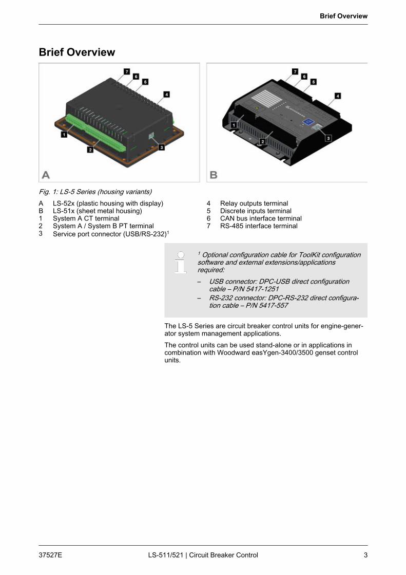
Fig. 1: LS-5 Series (housing variants)A LS-52x (plastic housing with display)B LS-51x (sheet metal housing)1 System A CT terminal2 System A / System B PT terminal3 Service port connector (USB/RS-232)1
4 Relay outputs terminal5 Discrete inputs terminal6 CAN bus interface terminal7 RS-485 interface terminal
1 Optional configuration cable for ToolKit configurationsoftware and external extensions/applicationsrequired:– USB connector: DPC-USB direct configuration
cable – P/N 5417-1251– RS-232 connector: DPC-RS-232 direct configura‐
tion cable – P/N 5417-557
The LS-5 Series are circuit breaker control units for engine-gener‐ator system management applications.The control units can be used stand-alone or in applications incombination with Woodward easYgen-3400/3500 genset controlunits.
Brief Overview
37527E LS-511/521 | Circuit Breaker Control 3

Fig. 2: Sample application setupA typical application mode for the control unit is the use as anexternal mains circuit breaker.n One or more gensets feed on a load busbar.n The easYgen(s) close and open their own generator breaker.n The LS-5 at the interchange point closes and opens the MCB.
For a listing of additional application modes and setupsplease refer to chapter Ä Chapter 6 “Application”on page 163.
The following parts are included in the scope of delivery. Pleasecheck prior to the installation that all parts are present.
Sample application setup
Scope of delivery
Brief Overview
37527ELS-511/521 | Circuit Breaker Control4
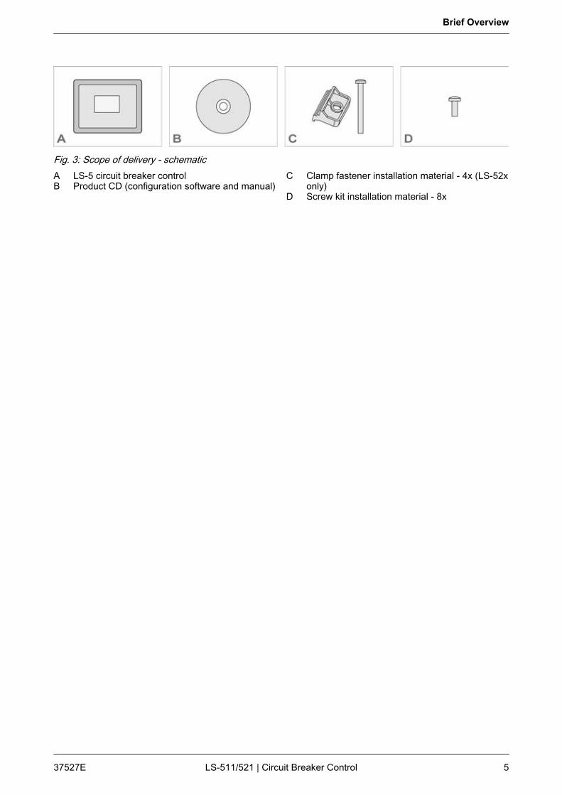
Fig. 3: Scope of delivery - schematicA LS-5 circuit breaker controlB Product CD (configuration software and manual)
C Clamp fastener installation material - 4x (LS-52xonly)
D Screw kit installation material - 8x
Brief Overview
37527E LS-511/521 | Circuit Breaker Control 5

Brief Overview
37527ELS-511/521 | Circuit Breaker Control6
Table of contents1 General Information................................................................................................................ 13
1.1 About This Manual.................................................................................................................... 131.1.1 Revision History........................................................................................................................ 131.1.2 Depiction Of Notes And Instructions......................................................................................... 141.2 Copyright And Disclaimer.......................................................................................................... 151.3 Service And Warranty............................................................................................................... 161.4 Safety........................................................................................................................................ 161.4.1 Intended Use............................................................................................................................. 161.4.2 Personnel.................................................................................................................................. 171.4.3 General Safety Notes................................................................................................................ 181.4.4 Protective Equipment And Tools............................................................................................... 21
2 System Overview..................................................................................................................... 23
2.1 Display And Status Indicators................................................................................................... 232.2 Hardware Interfaces (Terminals)............................................................................................... 242.3 Application Modes Overview..................................................................................................... 252.4 Synch. Check Functionality....................................................................................................... 25
3 Installation............................................................................................................................... 27
3.1 Mount Unit (Sheet Metal Housing)............................................................................................ 273.2 Mount Unit (Plastic Housing)..................................................................................................... 283.2.1 Clamp Fastener Installation....................................................................................................... 293.2.2 Screw Kit Installation................................................................................................................. 313.3 Setup Connections.................................................................................................................... 323.3.1 Terminal Allocation.................................................................................................................... 323.3.2 Wiring Diagram.......................................................................................................................... 343.3.3 Power Supply............................................................................................................................ 353.3.4 Voltage Measuring.................................................................................................................... 363.3.4.1 System A Voltage...................................................................................................................... 363.3.4.2 System B Voltage...................................................................................................................... 443.3.5 Current Measuring (System A).................................................................................................. 493.3.5.1 Parameter Setting 'L1 L2 L3'..................................................................................................... 503.3.5.2 Parameter Setting 'Phase L1' 'Phase L2' 'Phase L3'................................................................. 513.3.6 Power Measuring...................................................................................................................... 523.3.7 Power Factor Definition............................................................................................................. 523.3.8 Discrete Inputs.......................................................................................................................... 533.3.9 Relay Outputs (LogicsManager)................................................................................................ 553.3.10 Serial Interface.......................................................................................................................... 563.3.10.1 RS-485 Interface....................................................................................................................... 563.3.11 Service Port............................................................................................................................... 56
Table of contents
37527E LS-511/521 | Circuit Breaker Control 7
3.4 CAN Bus Interface..................................................................................................................... 583.5 Connecting 24 V Relays............................................................................................................ 60
4 Configuration........................................................................................................................... 61
4.1 Basic Setup............................................................................................................................... 614.1.1 Configure Language/Clock........................................................................................................ 614.1.2 Configure Display...................................................................................................................... 654.1.3 Enter Password......................................................................................................................... 654.1.4 System Management................................................................................................................ 674.1.5 Password System...................................................................................................................... 694.2 Configure Measurement............................................................................................................ 704.2.1 Configure Transformer.............................................................................................................. 734.3 Configure Monitoring................................................................................................................. 744.3.1 System A................................................................................................................................... 744.3.1.1 System A Operating Voltage / Frequency................................................................................. 754.3.1.2 System A Decoupling................................................................................................................ 764.3.1.3 System A Overfrequency (Levels 1 & 2) ANSI# 81O................................................................ 784.3.1.4 System A Underfrequency (Level 1 & 2) ANSI# 81U................................................................ 794.3.1.5 System A Overvoltage (Level 1 & 2) ANSI# 59......................................................................... 804.3.1.6 System A Undervoltage (Level 1 & 2) ANSI# 27....................................................................... 824.3.1.7 QV Monitoring........................................................................................................................... 834.3.1.8 Phase Shift................................................................................................................................ 854.3.1.9 df/dt (ROCOF)........................................................................................................................... 874.3.1.10 System A Phase Rotation......................................................................................................... 884.3.1.11 System A Voltage Asymmetry................................................................................................... 904.3.1.12 System A Voltage Increase....................................................................................................... 914.3.1.13 System A Time-Dependent Voltage.......................................................................................... 924.3.2 System B................................................................................................................................... 964.3.2.1 System B Operating Voltage / Frequency................................................................................. 964.3.2.2 System B Voltage Phase Rotation............................................................................................ 974.3.3 Breaker...................................................................................................................................... 994.3.3.1 Configure CBA.......................................................................................................................... 994.3.3.2 Synchronization CBA ............................................................................................................. 1004.3.3.3 CBA Unload Mismatch............................................................................................................ 1014.3.3.4 System A / System B Phase Rotation..................................................................................... 1014.3.4 Miscellaneous.......................................................................................................................... 1034.3.4.1 Alarm Acknowledgement......................................................................................................... 1034.3.4.2 CAN Interface.......................................................................................................................... 1034.3.4.3 Battery Overvoltage (Level 1 & 2)........................................................................................... 1044.3.4.4 Battery Undervoltage (Level 1 & 2)......................................................................................... 1054.3.4.5 Multi-Unit Missing Members.................................................................................................... 1064.4 Configure Application.............................................................................................................. 107
Table of contents
37527ELS-511/521 | Circuit Breaker Control8

4.4.1 Application Mode..................................................................................................................... 1074.4.2 Breakers.................................................................................................................................. 1094.4.2.1 Configure CBA........................................................................................................................ 1094.4.2.2 Phase Angle Compensation.................................................................................................... 1114.4.2.3 Phase Matching....................................................................................................................... 1144.4.2.4 Dead Bus Closure CBA........................................................................................................... 1144.4.2.5 Synchronization Configuration................................................................................................ 1154.4.3 Configure Segment................................................................................................................. 1164.4.4 Inputs And Outputs.................................................................................................................. 1174.4.4.1 Discrete Inputs........................................................................................................................ 1174.4.4.2 Discrete Outputs (LogicsManager).......................................................................................... 1204.4.5 Automatic Run......................................................................................................................... 1214.5 Configure Interfaces................................................................................................................ 1224.5.1 General.................................................................................................................................... 1224.5.2 CAN Interface.......................................................................................................................... 1224.5.2.1 CAN Interface 1....................................................................................................................... 1234.5.2.2 Additional Server SDOs (Service Data Objects)..................................................................... 1254.5.2.3 Receive PDO 1 (Process Data Object)................................................................................... 1264.5.2.4 Transmit PDO {x} (Process Data Object)................................................................................ 1274.5.3 RS-232 Interface..................................................................................................................... 1314.5.4 RS-485 Interface..................................................................................................................... 1314.5.5 Modbus Protocol (5300 Multiple)............................................................................................. 1324.6 Configure LogicsManager....................................................................................................... 1334.7 Configure Counters................................................................................................................. 138
5 Operation............................................................................................................................... 139
5.1 Access Via PC (ToolKit).......................................................................................................... 1395.1.1 Install ToolKit........................................................................................................................... 1395.1.2 Install ToolKit Configuration Files............................................................................................ 1415.1.3 Configure ToolKit..................................................................................................................... 1435.1.4 Connect ToolKit....................................................................................................................... 1435.1.5 View And Set Values In ToolKit............................................................................................... 1465.1.6 Special Screens...................................................................................................................... 1475.2 Front Panel Access................................................................................................................. 1505.2.1 Basic Navigation...................................................................................................................... 1505.2.2 Standard Menu Screens.......................................................................................................... 1555.2.2.1 Navigation Screens................................................................................................................. 1555.2.2.2 Status/Monitoring Screens...................................................................................................... 1555.2.2.3 Value Setting Screens............................................................................................................. 1565.2.3 Specialised Menu Screens...................................................................................................... 1575.2.3.1 Main Screen Voltage Display.................................................................................................. 1575.2.3.2 Alarm List................................................................................................................................ 157
Table of contents
37527E LS-511/521 | Circuit Breaker Control 9
5.2.3.3 Synchroscope.......................................................................................................................... 1585.2.3.4 LogicsManager Conditions...................................................................................................... 1585.2.3.5 LogicsManager........................................................................................................................ 1595.2.3.6 Event History........................................................................................................................... 1595.2.3.7 States easYgen....................................................................................................................... 1595.2.3.8 States LS-5.............................................................................................................................. 1605.2.3.9 Discrete Inputs/Outputs........................................................................................................... 1605.2.3.10 CAN Interface 1 State............................................................................................................. 1615.3 Restore Language Setting....................................................................................................... 161
6 Application............................................................................................................................. 163
6.1 Application Modes Overview................................................................................................... 1636.1.1 LS-5: Stand-Alone Application Mode...................................................................................... 1646.1.2 LS-5 & easYgen-3400/3500: Common Application Modes (LS-5 View)................................. 1646.1.3 easYgen-3400/3500 & LS-5: Common Application Modes (easYgen-3400/3500 View)........ 1666.2 Setup Stand-Alone Applications (Mode A01).......................................................................... 1686.3 Setup easYgen & Slave LS-5 Applications (Mode A03 & A04)............................................... 1716.3.1 Introduction.............................................................................................................................. 1716.3.2 Single Or Multiple easYgen With One Externally Operated MCB........................................... 1726.3.3 Multiple easYgen With One GGB And One Externally Operated MCB................................... 1766.3.4 Multiple easYgen With One Externally Operated GGB In Isolated Operation......................... 1816.3.5 Multiple easYgen With One Externally Operated GGB And One Externally Operated MCB. . 1846.4 Setup easYgen & Independent LS-5 Applications (Mode A02)............................................... 1896.4.1 Introduction.............................................................................................................................. 1896.4.2 General Functions................................................................................................................... 1916.4.2.1 General Preparation................................................................................................................ 1916.4.2.2 Setup Mains Measurement With easYgen.............................................................................. 1916.4.2.3 Setup Mains Decoupling With easYgen.................................................................................. 1926.4.2.4 Setup Mains Decoupling With LS-5......................................................................................... 1936.4.2.5 Setup Run-Up Synchronization In LS-5 Mode........................................................................ 1946.4.2.6 Setup AMF Start In LS-5 Mode............................................................................................... 1956.4.2.7 Setup Manual Breaker Control In LS-5 Mode......................................................................... 1976.4.2.8 Setup LS-5 Command Bits From easYgen To LS-5............................................................... 1976.4.2.9 Setup LS-5 Flags From LS-5 To LS-5 And easYgen.............................................................. 1986.4.3 H-Configuration With Two easYgen And Two Incoming Mains And Tie-breaker.................... 1996.4.4 Multiple Mains/Generators With Four easYgen Units, Two Incoming Mains And Different Tie-
breakers.................................................................................................................................. 210
7 Interfaces And Protocols...................................................................................................... 225
7.1 Interfaces Overview................................................................................................................. 2257.2 CAN Interfaces........................................................................................................................ 2267.2.1 CAN Interface 1 (Guidance level)............................................................................................ 226
Table of contents
37527ELS-511/521 | Circuit Breaker Control10

7.3 Serial Interfaces...................................................................................................................... 2267.3.1 Service Port (RS-232/USB)..................................................................................................... 2267.3.2 RS-485 Interface..................................................................................................................... 2277.4 CANopen Protocol................................................................................................................... 2277.5 Modbus Protocol..................................................................................................................... 229
8 Technical Specifications...................................................................................................... 233
8.1 Technical Data........................................................................................................................ 2338.1.1 Measuring Values.................................................................................................................... 2338.1.2 Ambient Variables................................................................................................................... 2348.1.3 Inputs/Outputs......................................................................................................................... 2348.1.4 Interface.................................................................................................................................. 2358.1.5 Battery..................................................................................................................................... 2358.1.6 Housing................................................................................................................................... 2358.1.7 Approvals................................................................................................................................ 2368.1.8 Generic Note........................................................................................................................... 2368.2 Environmental Data................................................................................................................. 2368.3 Accuracy.................................................................................................................................. 237
9 Appendix................................................................................................................................ 241
9.1 Characteristics......................................................................................................................... 2419.1.1 Triggering Characteristics....................................................................................................... 2419.2 Data Protocols......................................................................................................................... 2439.2.1 CANopen/Modbus................................................................................................................... 2439.2.1.1 Data Protocol 5301 (Basic Visualization)................................................................................ 2439.2.2 CANopen................................................................................................................................. 2589.2.2.1 Protocol 6003 (LS-5 Communication)..................................................................................... 2589.2.3 Modbus.................................................................................................................................... 2639.2.3.1 Data Protocol 5300 (Basic Visualization)................................................................................ 2639.3 LogicsManager Reference...................................................................................................... 2999.3.1 LogicsManager Overview........................................................................................................ 2999.3.2 Logical Symbols...................................................................................................................... 3019.3.3 Logical Outputs....................................................................................................................... 3029.3.4 Logical Command Variables................................................................................................... 3049.3.4.1 Group 00: Flags Condition 1................................................................................................... 3059.3.4.2 Group 01: Alarm System......................................................................................................... 3069.3.4.3 Group 02: Systems Condition................................................................................................. 3079.3.4.4 Group 04: Applications Condition............................................................................................ 3099.3.4.5 Group 05: Device Related Alarms........................................................................................... 3109.3.4.6 Group 06: System B Related Alarms...................................................................................... 3119.3.4.7 Group 07: System A Related Alarms...................................................................................... 3119.3.4.8 Group 08: System Related Alarms.......................................................................................... 312
Table of contents
37527E LS-511/521 | Circuit Breaker Control 11

9.3.4.9 Group 09: Discrete Inputs....................................................................................................... 3129.3.4.10 Group 11: Clock And Timer..................................................................................................... 3139.3.4.11 Group 13: Discrete Outputs..................................................................................................... 3139.3.4.12 Group 24: Flags Condition 2................................................................................................... 3149.3.4.13 Group 26: Flags Of LS5 (33 to 48).......................................................................................... 3159.3.4.14 Group 27: Flags Of LS5 (49 to 64).......................................................................................... 3179.3.4.15 Group 28: LS5 System Conditions.......................................................................................... 3209.3.4.16 Group 29: Commands Of EG (1 to 16).................................................................................... 3209.3.4.17 Group 30: Commands Of EG (17 to 32).................................................................................. 3239.3.5 Factory Settings...................................................................................................................... 3269.4 Event And Alarm Reference.................................................................................................... 3289.4.1 Alarm Classes......................................................................................................................... 3289.4.2 Status Messages..................................................................................................................... 3299.4.3 Event History........................................................................................................................... 3309.4.3.1 Event Messages...................................................................................................................... 3319.4.3.2 Alarm Messages...................................................................................................................... 3319.5 Additional Application Information........................................................................................... 3349.5.1 Synchronization Of System A and System B.......................................................................... 334
10 Glossary And List Of Abbreviations.................................................................................... 335
11 Index....................................................................................................................................... 337
Table of contents
37527ELS-511/521 | Circuit Breaker Control12

1 General Information1.1 About This Manual1.1.1 Revision History
Rev. Date Editor Changes in chronical descending order
E 2013-02-27 GG Corrections
n Undesired breaker close for synchronization when one system is configured to 1Ph2W andthe other system to 3Ph4W: problem solved.
Manual
n Chapter Ä Chapter 4.4.2.2 “Phase Angle Compensation” on page 111 renamed.n New overview table for synchronization matches System A with Sytem B. Refer to
Ä Chapter 9.5.1 “Synchronization Of System A and System B” on page 334 for details.n Minor changes.
D 2012-11-27 GG New device features & updates
Requirements: LS-511/521 circuit breaker control with software version 1.0104 or higher.
Feature updates
n The LS-5 now sends the unloading request– if the measured power is within the range for breaker opening (Parameter
8819 Ä p. 101) or– if the breaker open logic immediately is active (Parameter 8828 Ä p. 109,
12944 Ä p. 111).
Manual
n Minor changes.
C 2012-07-23 GG New device features & updates
Requirements: LS-511/521 circuit breaker control with software version 1.0103 or higher.
Feature updates
n Sync Check functionality with corresponding Command Variables.
Manual
n Sync Check function integrated. Refer to Ä Chapter 2.4 “Synch. Check Functionality”on page 25 for details.
n Password system's setting range: minimal value limited to 1. Refer to Ä Table on page 69for details.
n Typo corrections.n Layout and graphics adjustments.
General Information
About This Manual > Revision History
37527E LS-511/521 | Circuit Breaker Control 13
Rev. Date Editor Changes in chronical descending order
B 2012-03-22 TE Manual
n Typo correctionsn Design and graphics adjustments
New device features & updates
Requirements: LS-511/521 circuit breaker control with software version 1.0102 or higher. Thedescribed changes relate to the previous software version 1.0101.
Feature updates
n System A voltage monitoring. Refer to Ä Chapter 4.3.1 “System A” on page 74 for details.The setting range of "SyA. voltage monitoring" (parameter 1771 Ä p. 74) was extended tothe entry "All".
n System A time-dependent voltage monitoring. Refer to Ä Chapter 4.3.1.13 “System ATime-Dependent Voltage” on page 92 for details. The setting range of "Point 1 time"(parameter 4961 Ä p. 95) is configurable now.
A 2011-10-17 TE Manual
n Minor corrections
New device features & updates
Requirements: LS-511/521 circuit breaker control with software version 1.01xx or higher. Thedescribed changes relate to the previous software version 1.00xx.
New features
n QV monitoring. Refer to Ä Chapter 4.3.1.7 “QV Monitoring” on page 83 for details.n System A time-dependent voltage monitoring. Refer to chapter Ä Chapter 4.3.1.13
“System A Time-Dependent Voltage” on page 92 for details.n Connect synchronous segments (ring operation). Refer to Ä Chapter 4.3.3.1 “Configure
CBA” on page 99 for details (parameter 8852 Ä p. 110).
Feature updates
n System A voltage increase monitoring. Refer to Ä Chapter 4.3.1.12 “System A VoltageIncrease” on page 91 for details. Please be aware that this monitoring function waschanged with the new software version.
n System A undervoltage monitoring. Refer to Ä Chapter 4.3.1.6 “System A Undervoltage(Level 1 & 2) ANSI# 27” on page 82 for details. The setting range of "Limit" (parameter3004 Ä p. 82 and 3010 Ä p. 82) has been lowered from 50 % to 45 %.
NEW 2011-02-28 TE Release
1.1.2 Depiction Of Notes And InstructionsSafety instructions are marked with symbols in these instructions.The safety instructions are always introduced by signal words thatexpress the extent of the danger.
DANGER!This combination of symbol and signal word indicatesan immediately-dangerous situation that could causedeath or severe injuries if not avoided.
Safety instructions
General Information
About This Manual > Depiction Of Notes And Ins...
37527ELS-511/521 | Circuit Breaker Control14
WARNING!This combination of symbol and signal word indicatesa possibly-dangerous situation that could cause deathor severe injuries if it is not avoided.
CAUTION!This combination of symbol and signal word indicatesa possibly-dangerous situation that could cause slightinjuries if it is not avoided.
NOTICE!This combination of symbol and signal word indicatesa possibly-dangerous situation that could cause prop‐erty and environmental damage if it is not avoided.
This symbol indicates useful tips and recommenda‐tions as well as information for efficient and trouble-free operation.
To emphasize instructions, results, lists, references, and other ele‐ments, the following markings are used in these instructions:
Marking Explanation
Step-by-step instructions
ð Results of action steps
References to sections of these instructions and toother relevant documents
Listing without fixed sequence
[Buttons] Operating elements (e.g. buttons, switches), displayelements (e.g. signal lamps)
“Display” Screen elements (e.g. buttons, programming of func‐tion keys)
1.2 Copyright And DisclaimerDisclaimerAll information and instructions in this operating manual have beenprovided under due consideration of applicable guidelines and reg‐ulations, the current and known state of the art, as well as ourmany years of in-house experience. Woodward GmbH assumes noliability for damages due to:n Failure to comply with the instructions in this operating manualn Improper use / misuse
Tips and recommendations
Additional markings
General Information
Copyright And Disclaimer
37527E LS-511/521 | Circuit Breaker Control 15
n Willful operation by non-authorized personsn Unauthorized conversions or non-approved technical modifica‐
tionsn Use of non-approved spare partsThe originator is solely liable to the full extent for damages causedby such conduct. The agreed upon obligations in the delivery con‐tract, the general terms and conditions, the manufacturer’s deliveryconditions, and the statutory regulations valid at the time the con‐tract was concluded, apply.
CopyrightThis operating manual is protected by copyright. No part of thisoperating manual may be reproduced in any form or incorporatedinto any information retrieval system without written permission ofWoodward GmbH.Delivery of the operating manual to third parties, duplication in anyform - including excerpts - as well as exploitation and/or communi‐cation of the content, are not permitted without a written declara‐tion of release by Woodward GmbH.Actions to the contrary exact damage compensation. We reservethe right to enforce additional claims.
1.3 Service And WarrantyOur Customer Service is available for technical information.Please see page 2 for the contact data.In addition, our employees are constantly interested in new infor‐mation and experiences that arise from usage and could be val‐uable for the improvement of our products.
For information on the locally applicable warrantyterms, please refer to the sales documents providedwith the product.
1.4 Safety1.4.1 Intended Use
The circuit breaker control unit has been designed and constructedsolely for the intended use described in this manual.
Warranty terms
General Information
Safety > Intended Use
37527ELS-511/521 | Circuit Breaker Control16
The circuit breaker control unit must be used exclusively for engine-generatorsystem management applications.
n Intended use requires operation of the control unit within the specificationslisted in Ä Chapter 8.1 “Technical Data” on page 233.
n All permissible applications are outlined in Ä Chapter 6 “Application”on page 163.
n Intended use also includes compliance with all instructions and safety notespresented in this manual.
n Any use which exceeds or differs from the intended use shall be consideredimproper use.
n No claims of any kind for damage will be entertained if such claims resultfrom improper use.
NOTICE!Damage due to improper use!Improper use of the circuit breaker control unit maycause damage to the control unit as well as connectedcomponents.Improper use includes, but is not limited to:– Operation outside the specified operation condi‐
tions.
1.4.2 Personnel
WARNING!Hazards due to insufficiently qualified personnel!If unqualified personnel perform work on or with thecontrol unit hazards may arise which can causeserious injury and substantial damage to property.– Therefore, all work must only be carried out by
appropriately qualified personnel.
This manual specifies the personnel qualifications required for thedifferent areas of work, listed below:Qualified electricianThe qualified electrician is able to execute tasks on electricalequipment and independently detect and avoid any possible dan‐gers due to his training, expertise and experience, as well asknowledge of all applicable regulations.The qualified electrician has been specially trained for the workenvironment in which he is active and is familiar with all relevantstandards and regulations.
UserThe user operates the device within the limits of its intended use,without additional previous knowledge but according to the instruc‐tions and safety notes in this manual.
General Information
Safety > Personnel
37527E LS-511/521 | Circuit Breaker Control 17
The workforce must only consist of persons who can be expectedto carry out their work reliably. Persons with impaired reactions dueto, for example, the consumption of drugs, alcohol, or medicationare prohibited.When selecting personnel, the age-related and occupation-relatedregulations governing the usage location must be observed.
1.4.3 General Safety Notes
DANGER!Life-threatening hazard from electric shock!There is an imminent life-threatening hazard from elec‐tric shocks from live parts. Damage to insulation or tospecific components can pose a life-threateninghazard.– Only a qualified electrician should perform work on
the electrical equipment.– Immediately switch off the power supply and have
it repaired if there is damage to the insulation.– Before beginning work at live parts of electrical
systems and resources, cut the electricity andensure it remains off for the duration of the work.Comply with the five safety rules in the process:– cut electricity;– safeguard against restart;– ensure electricity is not flowing;– earth and short-circuit; and– cover or shield neighbouring live parts.
– Never bypass fuses or render them inoperable.Always use the correct amperage when changingfuses.
– Keep moisture away from live parts. Moisture cancause short circuits.
WARNING!Hazards due to insufficient prime mover protectionThe engine, turbine, or other type of prime movershould be equipped with an overspeed (overtempera-ture, or overpressure, where applicable) shutdowndevice(s), that operates totally independently of theprime mover control device(s) to protect against run‐away or damage to the engine, turbine, or other type ofprime mover with possible personal injury or loss of lifeshould the mechanical-hydraulic gov-ernor(s) or elec‐tric control(s), the actuator(s), fuel control(s), thedriving mechanism(s), the linkage(s), or the controlleddevice(s) fail.
Electrical hazards
Prime mover safety
General Information
Safety > General Safety Notes
37527ELS-511/521 | Circuit Breaker Control18
WARNING!Hazards due to unauthorized modificationsAny unauthorized modifications to or use of this equip‐ment outside its specified mechanical, electrical, orother operating limits may cause personal injury and/orproperty damage, including damage to the equipment.Any unauthorized modifications:– constitute "misuse" and/or "negligence" within the
meaning of the product warranty thereby excludingwarranty coverage for any resulting damage
– invalidate product certifications or listings.
NOTICE!Damage to the control system due to improperhandlingDisconnecting a battery from a control system thatuses an alternator or battery-charging device whilst thecharging device is still connected causes damage tothe control system.– Make sure the charging device is turned off before
disconnecting the battery from the system.
Protective equipment: n ESD wrist band
NOTICE!Damage from electrostatic dischargeAll electronic equipment sensitive to damage fromelectrostatic discharge, which can cause the controlunit to malfunction or fail.– To protect electronic components from static
damage, take the precautions listed below.
1. Avoid build-up of static electricity on your body by notwearing clothing made of synthetic materials. Wear cotton orcotton-blend materials as much as possible because thesedo not store static electric charges as easily as synthetics.
2. Before any maintenance work on the control unit, groundyourself by touching and holding a grounded metal object(pipes, cabinets, equipment, etc.) to discharge any staticelectricity.Alternatively wear an ESD wrist band connected to ground.
3. Keep plastic, vinyl, and Styrofoam materials (such as plasticor Styrofoam cups, cigarette packages, cellophane wrappers,vinyl books or folders, plastic bottles, etc.) away from thecontrol unit, modules and work area.
Modifications
Use of batteries/alternators
Electrostatic discharge
General Information
Safety > General Safety Notes
37527E LS-511/521 | Circuit Breaker Control 19
4. Opening the control cover may void the unit warranty. Do notremove the printed circuit board (PCB) from the control cab‐inet unless instructed by this manual.
If instructed by this manual to remove the PCBfrom the control cabinet, follow these precau‐tions:– Ensure that the device is completely voltage-
free (all connectors have to be discon‐nected).
– Do not touch any part of the PCB except theedges.
– Do not touch the electrical conductors, con‐nectors, or components with conductivedevices or with bare hands.
– When replacing a PCB, keep the new PCB inthe plastic antistatic protective bag it comesin until you are ready to install it. Immediatelyafter removing the old PCB from the controlcabinet, place it in the antistatic protectivebag.
For additional information on how to prevent damageto electronic components caused by improper han‐dling, read and observe the precautions in:– "Woodward manual 82715, Guide for Handling and
Protection of Electronic Controls, Printed CircuitBoards, and Modules".
Marine usage of the LS-5 circuit breaker control requires additionalprecautions as listed below:
The specified marine approvals are only valid forplastic housing units, if they are installed using thescrew kit.– Use all 8 screws and tighten accordingly.
n The LS-5 Series has no internally isolated power supply.
NOTICE!Malfunctions due to insufficient protection againstelectromagnetic interferenceExposure electromagnetic interference may causemalfunctions or incorrect internal readings.– Install an EMI filter (i.e. SCHAFFNER - FN
2070-3-06) for the power supply inputs when usingthe control unit in marine applications.
Notes on marine usage
General Information
Safety > General Safety Notes
37527ELS-511/521 | Circuit Breaker Control20
Some additional, independent safety and protectiondevices are necessary to meet safety requirements ofRules and Regulations of marine Classification Soci‐eties.– Please refer to the corresponding documents
issued by marine Classification Societies for theapplicable reqiurements.
1.4.4 Protective Equipment And ToolsPersonal protective equipment serves to protect risks to the safetyand health of persons as well as to protect delicate componentsduring work.Certain tasks presented in this manual require the personnel towear protective equipment. Specific required equipment is listed ineach individual set of instructions.The cumulative required personal protective equipment is detailedbelow:ESD wrist bandThe ESD (electrostatic discharge) wrist band keeps the user'sbody set to ground potential. This measure protects sensitive elec‐tronic components from damage due to electrostatic discharge.
Use of the proper tools ensures successful and safe execution oftasks presented in this manual.Specific required tools are listed in each individual set of instruc‐tions.The cumulative required tools are detailed below:Torque screwdriverA torque-screwdriver allow fastening of screws to a precisely speci‐fied torque.n Note the required torque range indiviually specified in the tasks
listed in this manual.
Protective gear
Tools
General Information
Safety > Protective Equipment And T...
37527E LS-511/521 | Circuit Breaker Control 21
General Information
Safety > Protective Equipment And T...
37527ELS-511/521 | Circuit Breaker Control22
2 System OverviewThis chapter provides a basic overview of the circuit breaker con‐trol unit.Refer to the comprehensive chapters indicated below to commis‐sion the control unit:n Ä Chapter 3 “Installation” on page 27 provides information on
how to mount the unit and setup connections.n Ä Chapter 4 “Configuration” on page 61 provides information
on basic setup and reference information on all configurableparameters.
n Ä Chapter 5 “Operation” on page 139 provides information onhow to access the unit via the front panel or remotely using theToolKit software provided by Woodward.
n Ä Chapter 6 “Application” on page 163 provides applicationexamples as well as instructions for the corresponding requiredconfiguration.
n Ä Chapter 7 “Interfaces And Protocols” on page 225 providesreference information on the usage of the interfaces and proto‐cols provided by the control unit.
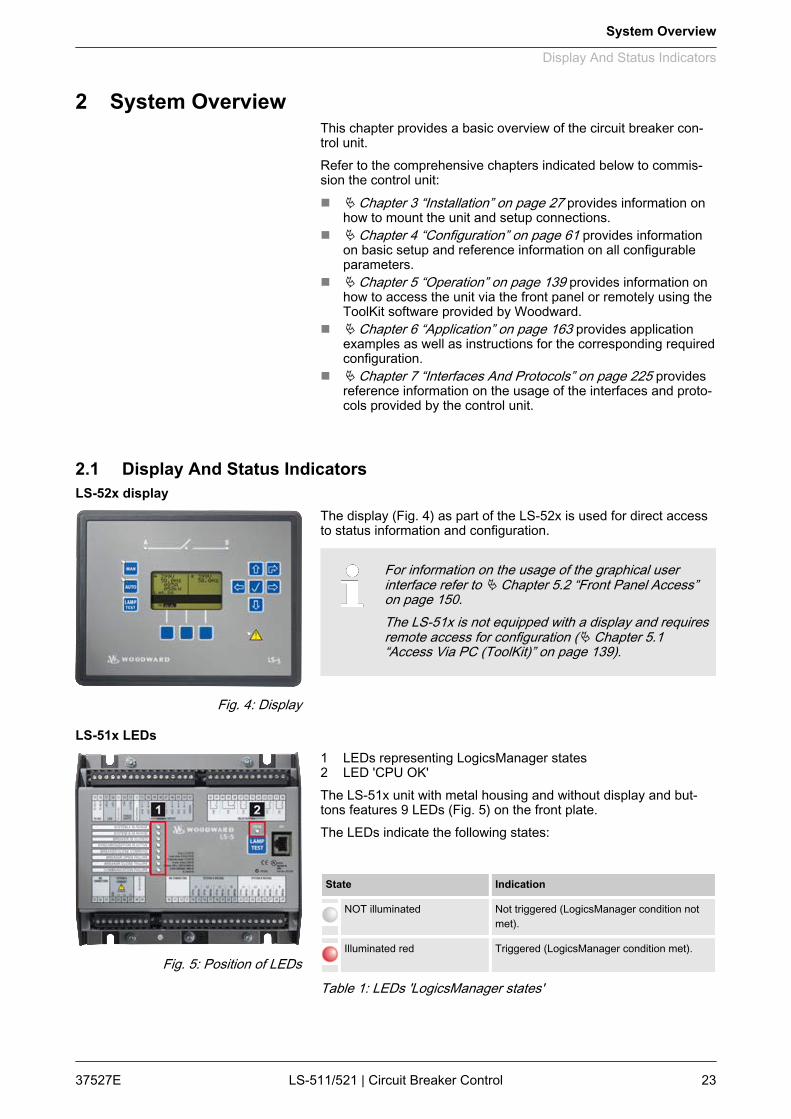
2.1 Display And Status Indicators
The display (Fig. 4) as part of the LS-52x is used for direct accessto status information and configuration.
For information on the usage of the graphical userinterface refer to Ä Chapter 5.2 “Front Panel Access”on page 150.The LS-51x is not equipped with a display and requiresremote access for configuration (Ä Chapter 5.1“Access Via PC (ToolKit)” on page 139).
1 LEDs representing LogicsManager states2 LED 'CPU OK'The LS-51x unit with metal housing and without display and but‐tons features 9 LEDs (Fig. 5) on the front plate.The LEDs indicate the following states:
State Indication
NOT illuminated Not triggered (LogicsManager condition notmet).
Illuminated red Triggered (LogicsManager condition met).
Table 1: LEDs 'LogicsManager states'
LS-52x display
Fig. 4: Display
LS-51x LEDs
Fig. 5: Position of LEDs
System Overview
Display And Status Indicators
37527E LS-511/521 | Circuit Breaker Control 23

State Indication
NOT illuminated CPU error/unit offline.
Illuminated green CPU OK.
Table 2: LED 'CPU OK'
DefaultsThe 8 LEDs representing LogicsManager states aretriggered based on the settings of parameters12962 Ä p. 135 to 12969 Ä p. 135.The conditions printed next to the LEDs on the sheetmetal housing represent the corresponding LogicsMa‐nager's parameter defaults.
2.2 Hardware Interfaces (Terminals)The LS-51x/52x (Fig. 6) provides the following terminals.
Fig. 6: LS-5 Series (housing variants)A LS-52x (plastic housing with display)B LS-51x (sheet metal housing)1 System A CT terminal2 System A / System B PT terminal3 Service port connector (USB/RS-232)1
4 Relay outputs terminal5 Discrete inputs terminal6 CAN bus interface terminal7 RS-485 interface terminal
1 Optional configuration cable for ToolKit configurationsoftware and external extensions/applicationsrequired:– USB connector: DPC-USB direct configuration
cable – P/N 5417-1251– RS-232 connector: DPC-RS-232 direct configura‐
tion cable – P/N 5417-557
System Overview
Hardware Interfaces (Termina...
37527ELS-511/521 | Circuit Breaker Control24
For information on how to setup connections refer toÄ Chapter 3.3 “Setup Connections” on page 32.For information on the interfaces and protocols refer toÄ Chapter 7 “Interfaces And Protocols” on page 225.
2.3 Application Modes OverviewThe circuit breaker control provides the following basic functionsvia the application modes listed below.
For detailed information on the application modes andspecial applications refer to Ä Chapter 6 “Application”on page 163.
Mode LS-5 Symbol Mode easYgen Symbol
LS-5 Single LS5 N/A N/A
LS-5 & easYgen LS5 (up to 16 unit) GCB/LS5
L-MCB (max. 1 unit) GCB/L-MCB
GCB/GGB/L-MCB
L-GGB (max. 1 unit) GCB/L-GGB
L-GGB (max. 1 unit) GCB/L-GGB/L-MCB
L-MCB (max. 1 unit)
2.4 Synch. Check FunctionalityTo use the LS-511/521 synchronization check functionality (Sync.Check) there are three command variables available for Logi‐csManager™:n 02.29 Sync. Conditionn 02.30 Dead Bus Closure Conditionn 02.28 Sync. Check Relay
WARNING!No dead bus interlocking!Synch. Check is intended to be a redundant checkfunction enhancing system security. Don't use for CBAcontrol!
General notes
System Overview
Synch. Check Functionality
37527E LS-511/521 | Circuit Breaker Control 25

The Sync. Check functionality is available in everyapplication mode, but be aware that application modescan fix parameters being relevant for this functionality.The application modes L-MCB ( ) and L-GGB ( )fix those parameters!Synchronization mode is “Phase Matching” only.(Parameter 5730, Synchronization CBA don't care.)
Synch. Check command variable don’t care about:– System conditions like blocking from other devices
e.g. dead bus interlocking– Synchronization signals from digital inputs (DI) like
enable close, CBA or open CBA– Synchronization control conditions like mains set‐
tling time
02.29 Sync Condition depends onn Voltage,n Frequency andn Phase angle.The command variable Sync Condition 02.29 Ä Chapter 9.3.4.3“Group 02: Systems Condition” on page 307 is true, if the phasematching synchronisation conditions are met according to parame‐ters 5711, 5712, 5710, 8825, 8824, 5713, 5714, and 5717. Param‐eter 5730 don’t care. For more details refer toÄ Table on page 112.
02.30 Dead Bus Closure Condition depends onn Voltage System A and System B andn Dead Bus configuration.The command variable Dead Bus Closure Condition 02.30Ä Chapter 9.3.4.3 “Group 02: Systems Condition” on page 307 istrue, if the dead bus closure conditions are met according toparameters 8801, 5820, 8805, 8802, 8803, and 8804. For moredetails refer to Ä Table on page 114.
02.28 Sync. Check Relay depends onn Sync. Check condition andn Dead Bus Closure condition.The command variable Sync. Check Relay 02.28Ä Chapter 9.3.4.3 “Group 02: Systems Condition” on page 307 istrue, if the phase matching synchronisation conditions are metaccording to parameters 5711, 5712, 5710, 8825, 8824, 5713,5714, and 5717 (parameter 5730 don’t care) orif the dead bus closure conditions are met according to parameters8801, 5820, 8805, 8802, 8803, and 8804.For more details refer to Ä Table on page 112 or Ä “Generalnotes” on page 114.
Variables and Parameters
System Overview
Synch. Check Functionality
37527ELS-511/521 | Circuit Breaker Control26

3 Installation3.1 Mount Unit (Sheet Metal Housing)
Fig. 7: Sheet metal housing - dimensions
Special tool: n Torque screwdriver
Proceed as follows to install the unit using the screw kit:
Fig. 8: Sheet metal housing - drill plan1. Drill the holes according to the dimensions in Fig. 8 (dimen‐
sions shown in mm).
Ensure sufficient clearance for access to the ter‐minals (top and bottom) and connectors locatedat the sides.
2. Mount the unit to the back panel and insert the screws.
Dimensions
Mounting into a cabinet
Installation
Mount Unit (Sheet Metal Hous...
37527E LS-511/521 | Circuit Breaker Control 27

3. Tighten the screws to a torque according to the quality classof the used screws.
Tighten the screws with a crosswise pattern toensure even pressure distribution.
If the thickness of the panel sheet exceeds 2.5mm, be sure to use screws with a lengthexceeding the panel sheet thickness by 4 mm.
3.2 Mount Unit (Plastic Housing)Mount the unit either using the clamp fasteners (Ä Chapter 3.2.1“Clamp Fastener Installation” on page 29) or the screw kit(Ä Chapter 3.2.2 “Screw Kit Installation” on page 31).
– Don't drill holes if you want to use the clamp fas‐teners. If the holes are drilled into the panel, theclamp fasteners cannot be used anymore.
– Some versions of the plastic housing are notequipped with nut inserts and may not be fastenedwith the screw kit.
– In order to enhance the protection to IP 66, fastenthe unit with the screw kit instead of the clamp fas‐tener hardware.
Fig. 9: Plastic housing - dimensions
Dimensions
Installation
Mount Unit (Plastic Housing)
37527ELS-511/521 | Circuit Breaker Control28
Measure Description Tolerance
H Height Total 171 mm ---
h Panel cutout 138 mm + 1.0 mm
h' Housingdimension
136 mm
W Width Total 219 mm ---
w Panel cutout 186 mm + 1.1 mm
w' Housingdimension
184 mm
Depth Total 61 mm ---
The maximum permissible corner radius is 3.5 mm.
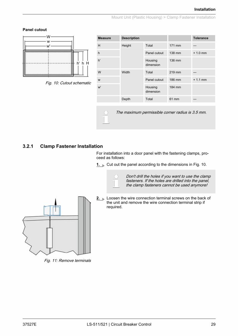
3.2.1 Clamp Fastener InstallationFor installation into a door panel with the fastening clamps, pro‐ceed as follows:1. Cut out the panel according to the dimensions in Fig. 10.
Don't drill the holes if you want to use the clampfasteners. If the holes are drilled into the panel,the clamp fasteners cannot be used anymore!
2. Loosen the wire connection terminal screws on the back ofthe unit and remove the wire connection terminal strip ifrequired.
Panel cutout
Fig. 10: Cutout schematic
Fig. 11: Remove terminals
Installation
Mount Unit (Plastic Housing) > Clamp Fastener Installation
37527E LS-511/521 | Circuit Breaker Control 29

3. Insert the four clamping screws into the clamp inserts fromthe shown side (Fig. 12; opposite the nut insert) until they arealmost flush. Do not completely insert the screws into theclamp inserts.
4. Insert the unit into the panel cutout. Verify that the unit fitscorrectly in the cutout. If the panel cutout is not big enough,enlarge it accordingly.
5. Re-install the clamp inserts by tilting the insert to a 45° angle.(Fig. 13/1) Insert the nose of the insert into the slot on theside of the housing. (Fig. 13/2) Raise the clamp insert so thatit is parallel to the control panel.
6. Tighten the clamping screws (Fig. 14/1) until the control unitis secured to the control panel (Fig. 14/2). Over tightening ofthese screws may result in the clamp inserts or the housingbreaking. Do not exceed the recommended tightening torqueof 0.1 Nm.
7. Reattach the wire connection terminal strip (Fig. 15) andsecure them with the side screws.
Fig. 12: Insert screws in clamps
Fig. 13: Attach clamp inserts
Fig. 14: Tighten clamping screws
Fig. 15: Reattach terminals
Installation
Mount Unit (Plastic Housing) > Clamp Fastener Installation
37527ELS-511/521 | Circuit Breaker Control30
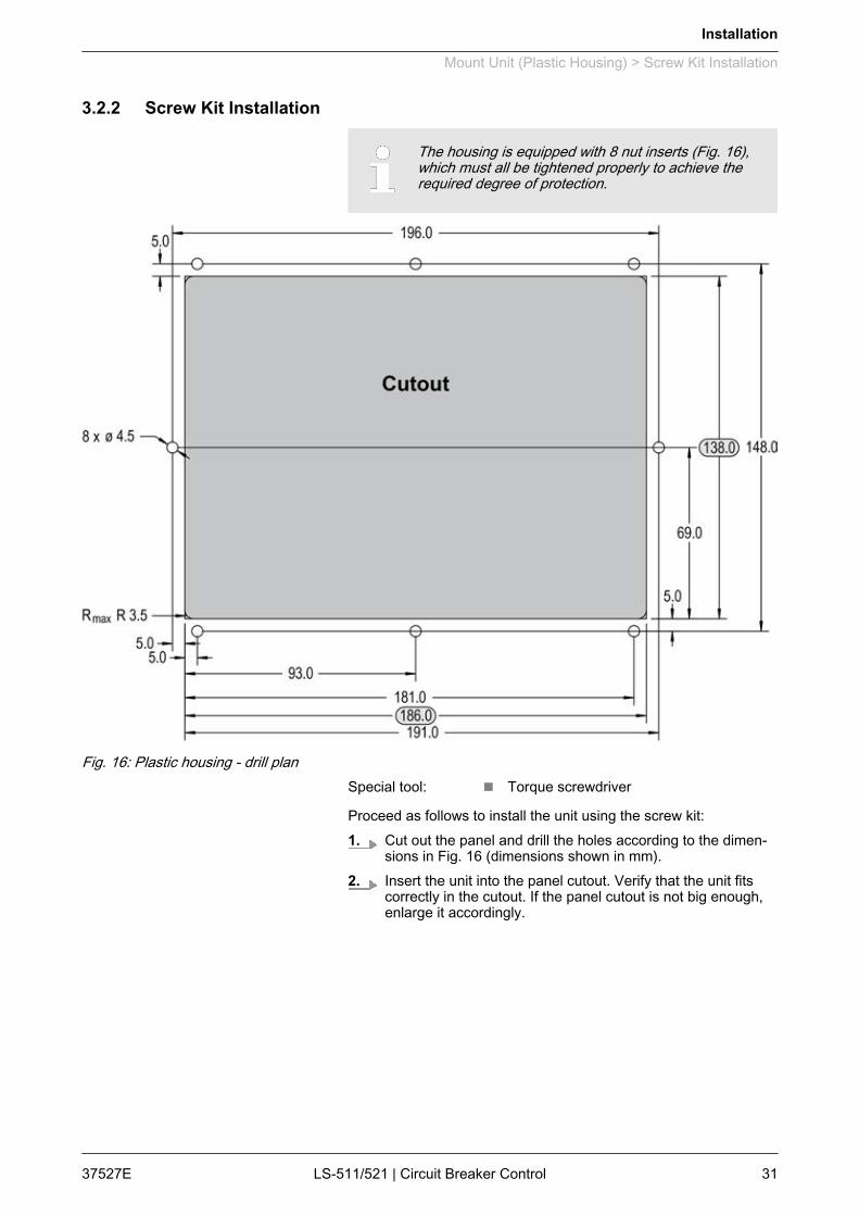
3.2.2 Screw Kit Installation
The housing is equipped with 8 nut inserts (Fig. 16),which must all be tightened properly to achieve therequired degree of protection.
Fig. 16: Plastic housing - drill planSpecial tool: n Torque screwdriver
Proceed as follows to install the unit using the screw kit:1. Cut out the panel and drill the holes according to the dimen‐
sions in Fig. 16 (dimensions shown in mm).2. Insert the unit into the panel cutout. Verify that the unit fits
correctly in the cutout. If the panel cutout is not big enough,enlarge it accordingly.
Installation
Mount Unit (Plastic Housing) > Screw Kit Installation
37527E LS-511/521 | Circuit Breaker Control 31
3. Insert the screws and tighten to 0.6 Nm (5.3 pound inches) oftorque.
Tighten the screws with a crosswise pattern toensure even pressure distribution.
If the thickness of the panel sheet exceeds 2.5mm, be sure to use screws with a lengthexceeding the panel sheet thickness by 4 mm.
3.3 Setup Connections
NOTICE!Malfunctions due to literal use of example valuesAll technical data and ratings indicated in this chapterare merely listed as examples. Literal use of thesevalues does not take into account all actual specifica‐tions of the control unit as delivered.– For definite values please refer to chapterÄ Chapter 8 “Technical Specifications”on page 233.
AWG mm² AWG mm² AWG mm² AWG mm² AWG mm² AWG mm²
30 0.05 21 0.38 14 2.5 4 25 3/0 95 600MCM 300
28 0.08 20 0.5 12 4 2 35 4/0 120 750MCM 400
26 0.14 18 0.75 10 6 1 50 300MCM 150 1000MCM 500
24 0.25 17 1.0 8 10 1/0 55 350MCM 185
22 0.34 16 1.5 6 16 2/0 70 500MCM 240
Table 3: Conversion chart - wire sizes
3.3.1 Terminal AllocationThe device terminals are allocated as follows:n Plastic housing - shown in Fig. 17n Sheet metal housing - shown in Fig. 18
General notes
Wire sizes
General notes
Installation
Setup Connections > Terminal Allocation
37527ELS-511/521 | Circuit Breaker Control32

Fig. 17: Plastic housing
Fig. 18: Sheet metal housing
Installation
Setup Connections > Terminal Allocation
37527E LS-511/521 | Circuit Breaker Control 33

3.3.2 Wiring Diagram
Fig. 19: Wiring diagram
Installation
Setup Connections > Wiring Diagram
37527ELS-511/521 | Circuit Breaker Control34

3.3.3 Power Supply
WARNING!Risk of electric shock - plastic housing– Connect Function Earth to the unit to avoid the risk
of electric shock.Setup the connection using screw-plug-ter‐minal 55.
– The conductor providing the connection must havea wire larger than or equal to 2.5 mm² (14 AWG).The connection must be performed properly.
WARNING!Risk of electric shock - sheet metal housing– Connect Protective Earth (PE) to the unit to avoid
the risk of electric shock.Use the protective earth (PE) connector located atthe bottom center of the sheet metal housing.
– The conductor providing the connection must havea wire larger than or equal to 2.5 mm² (14 AWG).The connection must be performed properly.
Woodward recommends to use one of the followingslow-acting protective devices in the supply line to ter‐minal 53:– Fuse NEOZED D01 6A or equivalent or– Miniature Circuit Breaker 6A / Type C
(for example: ABB type: S271C6 or equivalent)
Fig. 20: Power supply - wiring
Terminal Description Amax
A 55 Function earth (LS-52x models only) 2.5 mm²
B 53 12/24Vdc (8 to 40.0 Vdc) 2.5 mm²
C 54 0 Vdc 2.5 mm²
Table 4: Power supply - terminal assignment
General notes
Schematic and terminals
Installation
Setup Connections > Power Supply
37527E LS-511/521 | Circuit Breaker Control 35

Fig. 21: Power supply - crank waveform
3.3.4 Voltage Measuring
NOTICE!Incorrect readings due to improper setupThe control unit will not measure voltage correctly ifthe 120 V and 480 V inputs are utilized simultaneously.– Never use both sets of voltage measuring inputs.
Woodward recommends protecting the voltage meas‐uring inputs with slow-acting fuses rated for 2 to 6 A.
3.3.4.1 System A Voltage
If parameter 1800 Ä p. 73 ("SyA PT secondary ratedvolt.") is configured with a value between 50 and130 V, the 120 V input terminals must be used forproper measurement.If parameter 1800 Ä p. 73 ("SyA PT secondary ratedvolt.") is configured with a value between 131 and480 V, the 480 V input terminals must be used forproper measurement.
Characteristics
General notes
General notes
Installation
Setup Connections > Voltage Measuring > System A Voltage
37527ELS-511/521 | Circuit Breaker Control36
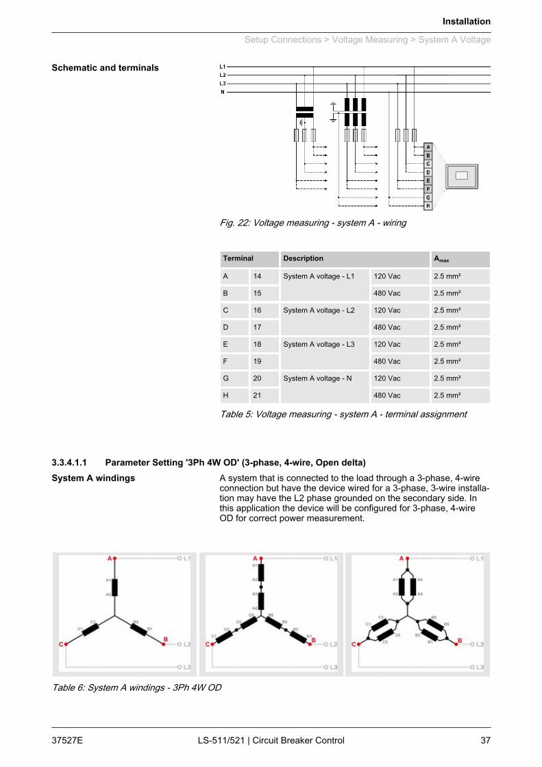
Fig. 22: Voltage measuring - system A - wiring
Terminal Description Amax
A 14 System A voltage - L1 120 Vac 2.5 mm²
B 15 480 Vac 2.5 mm²
C 16 System A voltage - L2 120 Vac 2.5 mm²
D 17 480 Vac 2.5 mm²
E 18 System A voltage - L3 120 Vac 2.5 mm²
F 19 480 Vac 2.5 mm²
G 20 System A voltage - N 120 Vac 2.5 mm²
H 21 480 Vac 2.5 mm²
Table 5: Voltage measuring - system A - terminal assignment
3.3.4.1.1 Parameter Setting '3Ph 4W OD' (3-phase, 4-wire, Open delta)A system that is connected to the load through a 3-phase, 4-wireconnection but have the device wired for a 3-phase, 3-wire installa‐tion may have the L2 phase grounded on the secondary side. Inthis application the device will be configured for 3-phase, 4-wireOD for correct power measurement.
Table 6: System A windings - 3Ph 4W OD
Schematic and terminals
System A windings
Installation
Setup Connections > Voltage Measuring > System A Voltage
37527E LS-511/521 | Circuit Breaker Control 37

Fig. 23: Measuring inputs - 3Ph 4W OD
3Ph 4W Wiring terminals
Rated voltage (range) 120 V (50 to 130 Veff.) 480 V (131 to 480 Veff.)
Measuring range (max.) 0 to 150 Vac 0 to 600 Vac
Terminal A C E G B D F H
14 16 18 20 15 17 19 21
Phase L1 L2 L3 --- L1 L2 L3 ---
For different voltage systems, different wiring terminalshave to be used.
3.3.4.1.2 Parameter Setting '3Ph 4W' (3-phase, 4-wire)
Table 7: System A windings - 3Ph 4W
Measuring inputs
Terminal assignment
System A windings
Installation
Setup Connections > Voltage Measuring > System A Voltage
37527ELS-511/521 | Circuit Breaker Control38
Fig. 24: Measuring inputs - 3Ph 4W
3Ph 4W Wiring terminals
Rated voltage (range) 120 V (50 to 130 Veff.) 480 V (131 to 480 Veff.)
Measuring range (max.) 0 to 150 Vac 0 to 600 Vac
Terminal A C E G B D F H
14 16 18 20 15 17 19 21
Phase L1 L2 L3 N L1 L2 L3 N
For different voltage systems, different wiring terminalshave to be used.Incorrect measurements are possible, if both voltagesystems use the same N terminal.
3.3.4.1.3 Parameter Setting '3Ph 3W' (3-phase, 3-wire)
Table 8: System A windings - 3Ph 3W
Measuring inputs
Terminal assignment
System A windings
Installation
Setup Connections > Voltage Measuring > System A Voltage
37527E LS-511/521 | Circuit Breaker Control 39

Fig. 25: Measuring inputs - 3Ph 3W
3Ph 3W Wiring terminals
Rated voltage (range) 120 V (50 to 130 Veff.) 480 V (131 to 480 Veff.)
Measuring range (max.) 0 to 150 Vac 0 to 600 Vac
Terminal A C E G B D F H
14 16 18 20 15 17 19 21
Phase L1 L2 L3 --- L1 L2 L3 ---
For different voltage systems, different wiring terminalshave to be used.
3.3.4.1.4 Parameter Setting '1Ph 3W' (1-phase, 3-wire)
Table 9: System A windings - 1Ph 3W
Measuring inputs
Terminal assignment
System A windings
Installation
Setup Connections > Voltage Measuring > System A Voltage
37527ELS-511/521 | Circuit Breaker Control40

Fig. 26: Measuring inputs - 1Ph 3W
1Ph 3W Wiring terminals
Rated voltage (range) 120 V (50 to 130 Veff.) 480 V (131 to 480 Veff.)
Measuring range (max.) 0 to 150 Vac 0 to 600 Vac
Terminal A C E G B D F H
14 16 18 20 15 17 19 21
Phase L1 N L3 N L1 N L3 N
For different voltage systems, different wiring terminalshave to be used.Incorrect measurements are possible, if both voltagesystems use the same N terminal.
3.3.4.1.5 Parameter Setting '1Ph 2W' (1-phase, 2-wire)
The 1-phase, 2-wire measurement may be performedphase-neutral or phase-phase.– Please note to configure and wire the LS-5 consis‐
tently.
Measuring inputs
Terminal assignment
Installation
Setup Connections > Voltage Measuring > System A Voltage
37527E LS-511/521 | Circuit Breaker Control 41
'1Ph 2W' Phase-Neutral Measuring
Table 10: System A windings - 1Ph 2W (phase neutral)
Fig. 27: Measuring inputs - 1Ph 2W (phase neutral)
1Ph 2W Wiring terminals
Rated voltage (range) 120 V (50 to 130 Veff.) 480 V (131 to 480 Veff.)
Measuring range (max.) 0 to 150 Vac 0 to 600 Vac
Terminal A C E G B D F H
14 16 18 20 15 17 19 21
Phase L1 N N N L1 N N N
For different voltage systems, different wiring terminalshave to be used.Incorrect measurements are possible if both voltagesystems use the same N terminal.
System A windings
Measuring inputs
Terminal assignment
Installation
Setup Connections > Voltage Measuring > System A Voltage
37527ELS-511/521 | Circuit Breaker Control42
'1Ph 2W' Phase-Phase Measuring
Table 11: System A windings - 1Ph 2W (phase-phase)
Fig. 28: Measuring inputs - 1Ph 2W (phase-phase)
1Ph 2W Wiring terminals
Rated voltage (range) 120 V (50 to 130 Veff.) 480 V (131 to 480 Veff.)
Measuring range (max.) 0 to 150 Vac 0 to 600 Vac
Terminal A C E G B D F H
14 16 18 20 15 17 19 21
Phase L1 L2 --- --- L1 L2 --- ---
For different voltage systems, different wiring terminalshave to be used.
System A windings
Measuring inputs
Terminal assignment
Installation
Setup Connections > Voltage Measuring > System A Voltage
37527E LS-511/521 | Circuit Breaker Control 43
3.3.4.2 System B Voltage
If parameter 1803 Ä p. 74 ("SyB PT secondary ratedvolt.") is configured with a value between 50 and 130V, the 120 V input terminals must be used for propermeasurement.If parameter 1803 Ä p. 74 ("SyB PT secondary ratedvolt.") is configured with a value between 131 and 480V, the 480 V input terminals must be used for propermeasurement.
Fig. 29: Voltage measuring - system B - wiring
Terminal Description Amax
A 22 System B voltage - L1 120 Vac 2.5 mm²
B 23 480 Vac 2.5 mm²
C 24 System B voltage - L2 120 Vac 2.5 mm²
D 25 480 Vac 2.5 mm²
E 26 System B voltage - L3 120 Vac 2.5 mm²
F 27 480 Vac 2.5 mm²
G 28 System B voltage - N 120 Vac 2.5 mm²
H 29 480 Vac 2.5 mm²
Table 12: Voltage measuring - system B - terminal assignment
General notes
Schematic and terminals
Installation
Setup Connections > Voltage Measuring > System B Voltage
37527ELS-511/521 | Circuit Breaker Control44
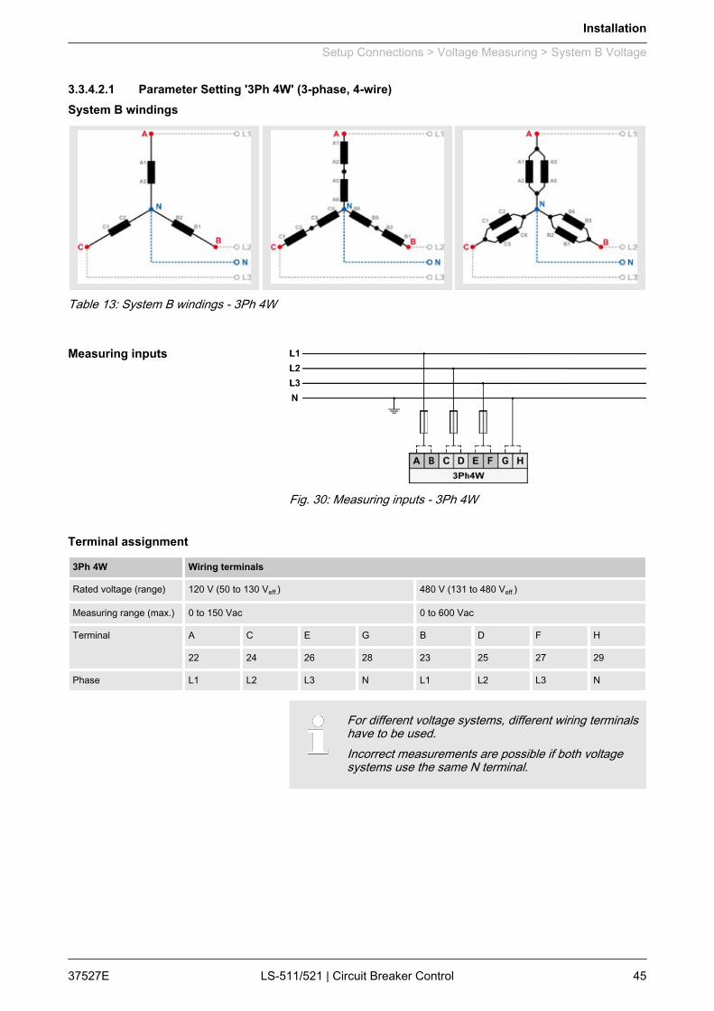
3.3.4.2.1 Parameter Setting '3Ph 4W' (3-phase, 4-wire)
Table 13: System B windings - 3Ph 4W
Fig. 30: Measuring inputs - 3Ph 4W
3Ph 4W Wiring terminals
Rated voltage (range) 120 V (50 to 130 Veff.) 480 V (131 to 480 Veff.)
Measuring range (max.) 0 to 150 Vac 0 to 600 Vac
Terminal A C E G B D F H
22 24 26 28 23 25 27 29
Phase L1 L2 L3 N L1 L2 L3 N
For different voltage systems, different wiring terminalshave to be used.Incorrect measurements are possible if both voltagesystems use the same N terminal.
System B windings
Measuring inputs
Terminal assignment
Installation
Setup Connections > Voltage Measuring > System B Voltage
37527E LS-511/521 | Circuit Breaker Control 45
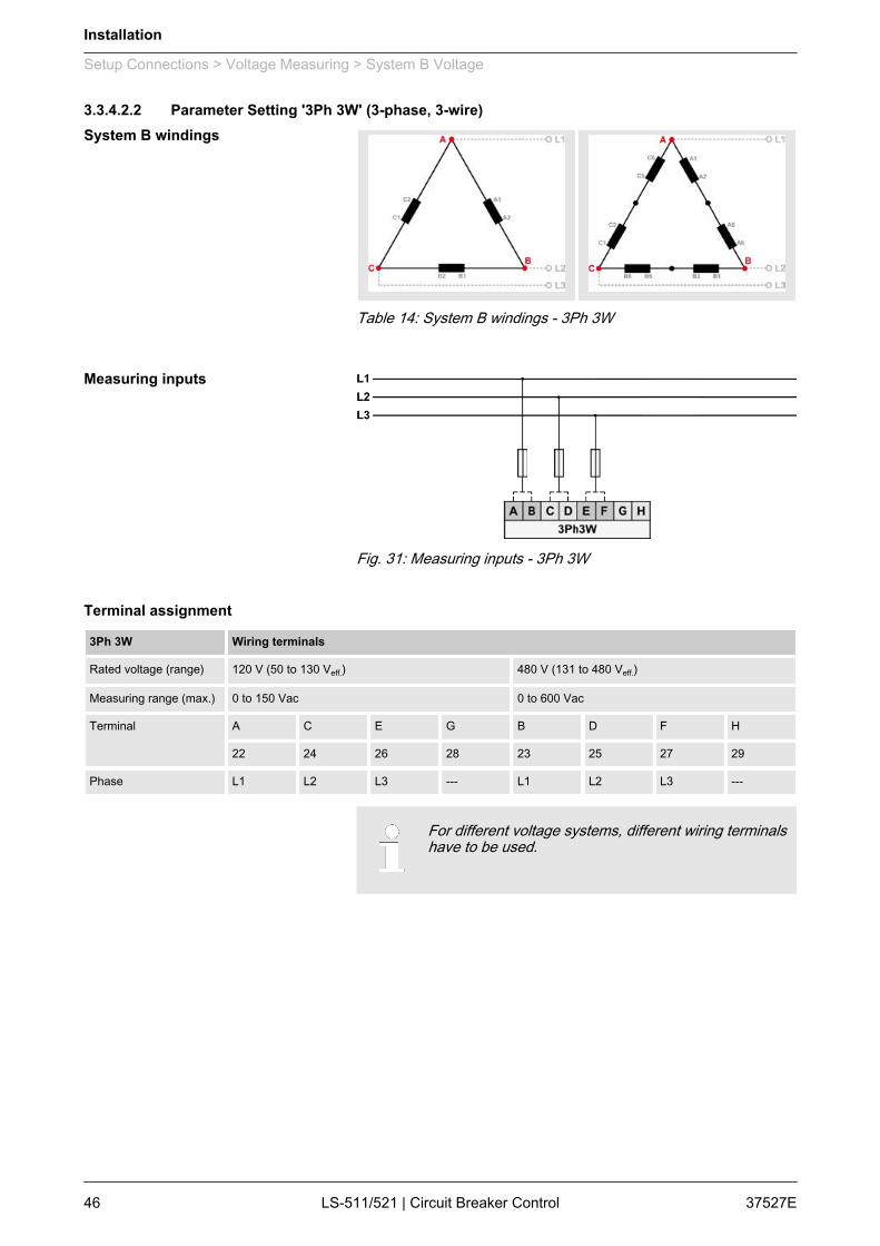
3.3.4.2.2 Parameter Setting '3Ph 3W' (3-phase, 3-wire)
Table 14: System B windings - 3Ph 3W
Fig. 31: Measuring inputs - 3Ph 3W
3Ph 3W Wiring terminals
Rated voltage (range) 120 V (50 to 130 Veff.) 480 V (131 to 480 Veff.)
Measuring range (max.) 0 to 150 Vac 0 to 600 Vac
Terminal A C E G B D F H
22 24 26 28 23 25 27 29
Phase L1 L2 L3 --- L1 L2 L3 ---
For different voltage systems, different wiring terminalshave to be used.
System B windings
Measuring inputs
Terminal assignment
Installation
Setup Connections > Voltage Measuring > System B Voltage
37527ELS-511/521 | Circuit Breaker Control46

3.3.4.2.3 Parameter Setting '1Ph 3W' (1-phase, 3-wire)
Table 15: System B windings - 1Ph 3W
Fig. 32: Measuring inputs - 1Ph 3W
1Ph 3W Wiring terminals
Rated voltage (range) 120 V (50 to 130 Veff.) 480 V (131 to 480 Veff.)
Measuring range (max.) 0 to 150 Vac 0 to 600 Vac
Terminal A C E G B D F H
22 24 26 28 23 25 27 29
Phase L1 N L3 N L1 N L3 N
For different voltage systems, different wiring terminalshave to be used.Incorrect measurements are possible, if both voltagesystems use the same N terminal.
System B windings
Measuring inputs
Terminal assignment
Installation
Setup Connections > Voltage Measuring > System B Voltage
37527E LS-511/521 | Circuit Breaker Control 47
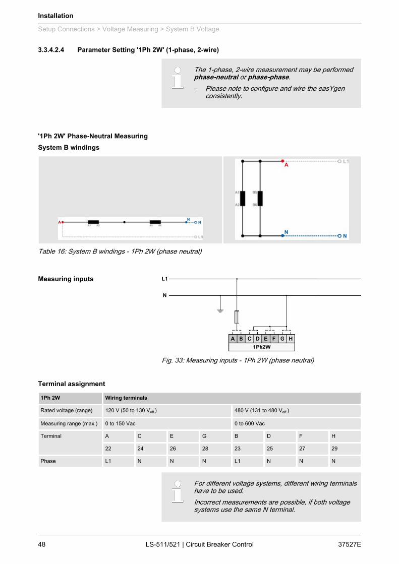
3.3.4.2.4 Parameter Setting '1Ph 2W' (1-phase, 2-wire)
The 1-phase, 2-wire measurement may be performedphase-neutral or phase-phase.– Please note to configure and wire the easYgen
consistently.
'1Ph 2W' Phase-Neutral Measuring
Table 16: System B windings - 1Ph 2W (phase neutral)
Fig. 33: Measuring inputs - 1Ph 2W (phase neutral)
1Ph 2W Wiring terminals
Rated voltage (range) 120 V (50 to 130 Veff.) 480 V (131 to 480 Veff.)
Measuring range (max.) 0 to 150 Vac 0 to 600 Vac
Terminal A C E G B D F H
22 24 26 28 23 25 27 29
Phase L1 N N N L1 N N N
For different voltage systems, different wiring terminalshave to be used.Incorrect measurements are possible, if both voltagesystems use the same N terminal.
System B windings
Measuring inputs
Terminal assignment
Installation
Setup Connections > Voltage Measuring > System B Voltage
37527ELS-511/521 | Circuit Breaker Control48
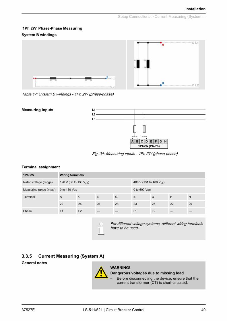
'1Ph 2W' Phase-Phase Measuring
Table 17: System B windings - 1Ph 2W (phase-phase)
Fig. 34: Measuring inputs - 1Ph 2W (phase-phase)
1Ph 2W Wiring terminals
Rated voltage (range) 120 V (50 to 130 Veff.) 480 V (131 to 480 Veff.)
Measuring range (max.) 0 to 150 Vac 0 to 600 Vac
Terminal A C E G B D F H
22 24 26 28 23 25 27 29
Phase L1 L2 --- --- L1 L2 --- ---
For different voltage systems, different wiring terminalshave to be used.
3.3.5 Current Measuring (System A)
WARNING!Dangerous voltages due to missing load– Before disconnecting the device, ensure that the
current transformer (CT) is short-circuited.
System B windings
Measuring inputs
Terminal assignment
General notes
Installation
Setup Connections > Current Measuring (System ...
37527E LS-511/521 | Circuit Breaker Control 49
Generally, one line of the current transformers secon‐dary must be grounded close to the CT.
Fig. 35: Current measuring - system A - wiring
Terminal Description Amax
A 7 System A current - L3 2.5 mm²
B 4 System A current - L3 (GND) 2.5 mm²
C 6 System A current - L2 2.5 mm²
D 4 System A current - L2 (GND) 2.5 mm²
E 5 System A current - L1 2.5 mm²
F 4 System A current - L1 (GND) 2.5 mm²
Table 18: Current measuring - system A - terminal assignment
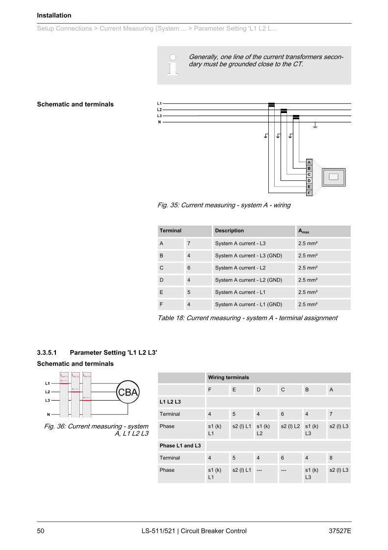
3.3.5.1 Parameter Setting 'L1 L2 L3'
Wiring terminals
F E D C B A
L1 L2 L3
Terminal 4 5 4 6 4 7
Phase s1 (k)L1
s2 (l) L1 s1 (k)L2
s2 (l) L2 s1 (k)L3
s2 (l) L3
Phase L1 and L3
Terminal 4 5 4 6 4 8
Phase s1 (k)L1
s2 (l) L1 --- --- s1 (k)L3
s2 (l) L3
Schematic and terminals
Schematic and terminals
Fig. 36: Current measuring - systemA, L1 L2 L3
Installation
Setup Connections > Current Measuring (System ... > Parameter Setting 'L1 L2 L...
37527ELS-511/521 | Circuit Breaker Control50
"Phase L1 and L3" applies if the system A voltagemeasurement is configured to 1Ph 3W(Ä Chapter 3.3.4.1.4 “ Parameter Setting '1Ph 3W' (1-phase, 3-wire)” on page 40).
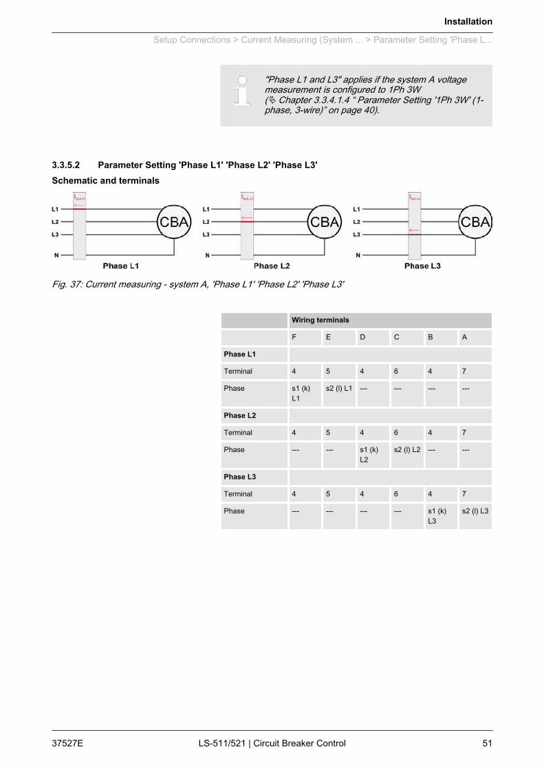
3.3.5.2 Parameter Setting 'Phase L1' 'Phase L2' 'Phase L3'
Fig. 37: Current measuring - system A, 'Phase L1' 'Phase L2' 'Phase L3'
Wiring terminals
F E D C B A
Phase L1
Terminal 4 5 4 6 4 7
Phase s1 (k)L1
s2 (l) L1 --- --- --- ---
Phase L2
Terminal 4 5 4 6 4 7
Phase --- --- s1 (k)L2
s2 (l) L2 --- ---
Phase L3
Terminal 4 5 4 6 4 7
Phase --- --- --- --- s1 (k)L3
s2 (l) L3
Schematic and terminals
Installation
Setup Connections > Current Measuring (System ... > Parameter Setting 'Phase L...
37527E LS-511/521 | Circuit Breaker Control 51
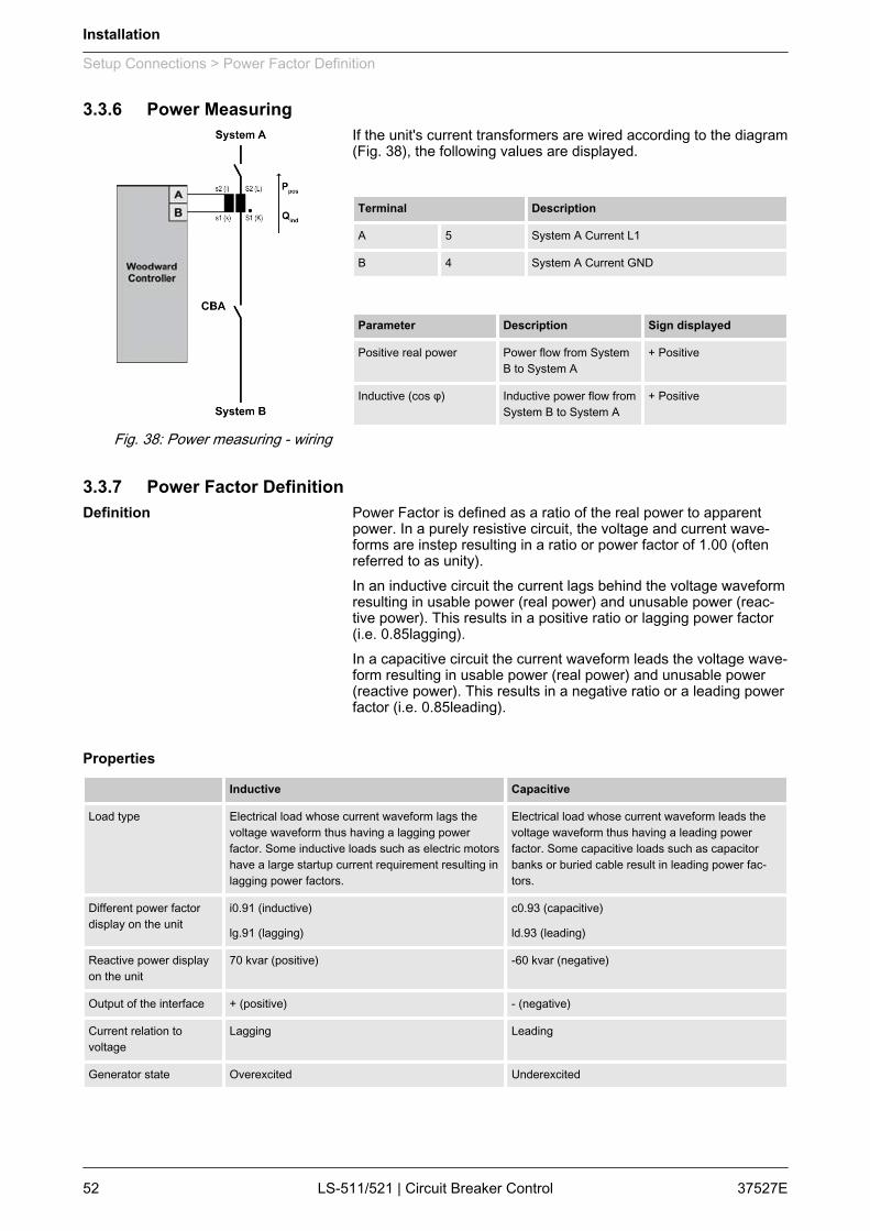
3.3.6 Power MeasuringIf the unit's current transformers are wired according to the diagram(Fig. 38), the following values are displayed.
Terminal Description
A 5 System A Current L1
B 4 System A Current GND
Parameter Description Sign displayed
Positive real power Power flow from SystemB to System A
+ Positive
Inductive (cos φ) Inductive power flow fromSystem B to System A
+ Positive
3.3.7 Power Factor DefinitionPower Factor is defined as a ratio of the real power to apparentpower. In a purely resistive circuit, the voltage and current wave‐forms are instep resulting in a ratio or power factor of 1.00 (oftenreferred to as unity).In an inductive circuit the current lags behind the voltage waveformresulting in usable power (real power) and unusable power (reac‐tive power). This results in a positive ratio or lagging power factor(i.e. 0.85lagging).In a capacitive circuit the current waveform leads the voltage wave‐form resulting in usable power (real power) and unusable power(reactive power). This results in a negative ratio or a leading powerfactor (i.e. 0.85leading).
Inductive Capacitive
Load type Electrical load whose current waveform lags thevoltage waveform thus having a lagging powerfactor. Some inductive loads such as electric motorshave a large startup current requirement resulting inlagging power factors.
Electrical load whose current waveform leads thevoltage waveform thus having a leading powerfactor. Some capacitive loads such as capacitorbanks or buried cable result in leading power fac‐tors.
Different power factordisplay on the unit
i0.91 (inductive)
lg.91 (lagging)
c0.93 (capacitive)
ld.93 (leading)
Reactive power displayon the unit
70 kvar (positive) -60 kvar (negative)
Output of the interface + (positive) - (negative)
Current relation tovoltage
Lagging Leading
Generator state Overexcited Underexcited
Fig. 38: Power measuring - wiring
Definition
Properties
Installation
Setup Connections > Power Factor Definition
37527ELS-511/521 | Circuit Breaker Control52
Inductive Capacitive
Control signal If the control unit is equipped with a power factor controller while in parallel with the utility:
A voltage lower "-" signal is output as long as themeasured value is "more inductive" than the refer‐ence setpoint
Example: measured = i0.91; setpoint = i0.95
A voltage raise "+" signal is output as long as themeasured value is "more capacitive" than the refer‐ence setpoint
Example: measured = c0.91; setpoint = c0.95
The phasor diagram is used from the generator's view.
Inductive Capacitive
Diagram
3.3.8 Discrete Inputs
The discrete inputs are electrically isolated which per‐mits the polarity of the connections to be either positiveor negative.– All discrete inputs must use the same polarity,
either positive or negative signals, due to thecommon ground.
Fig. 39: Discrete input - positive polarity signal
Phasor diagram
General notes
Schematic and terminal assign‐ment
Installation
Setup Connections > Discrete Inputs
37527E LS-511/521 | Circuit Breaker Control 53
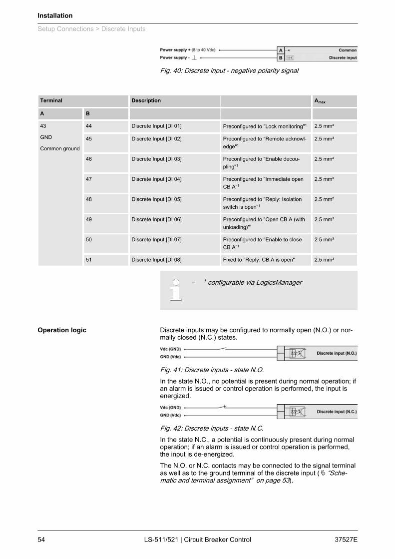
Fig. 40: Discrete input - negative polarity signal
Terminal Description Amax
A B 43
GND
Common ground
44 Discrete Input [DI 01] Preconfigured to "Lock monitoring"1 2.5 mm²
45 Discrete Input [DI 02] Preconfigured to "Remote acknowl‐edge"1
2.5 mm²
46 Discrete Input [DI 03] Preconfigured to "Enable decou‐pling"1
2.5 mm²
47 Discrete Input [DI 04] Preconfigured to "Immediate openCB A"1
2.5 mm²
48 Discrete Input [DI 05] Preconfigured to "Reply: Isolationswitch is open"1
2.5 mm²
49 Discrete Input [DI 06] Preconfigured to "Open CB A (withunloading)"1
2.5 mm²
50 Discrete Input [DI 07] Preconfigured to "Enable to closeCB A"1
2.5 mm²
51 Discrete Input [DI 08] Fixed to "Reply: CB A is open" 2.5 mm²
– 1 configurable via LogicsManager
Discrete inputs may be configured to normally open (N.O.) or nor‐mally closed (N.C.) states.
Fig. 41: Discrete inputs - state N.O.In the state N.O., no potential is present during normal operation; ifan alarm is issued or control operation is performed, the input isenergized.
Fig. 42: Discrete inputs - state N.C.In the state N.C., a potential is continuously present during normaloperation; if an alarm is issued or control operation is performed,the input is de-energized.The N.O. or N.C. contacts may be connected to the signal terminalas well as to the ground terminal of the discrete input (Ä “Sche‐matic and terminal assignment” on page 53).
Operation logic
Installation
Setup Connections > Discrete Inputs
37527ELS-511/521 | Circuit Breaker Control54
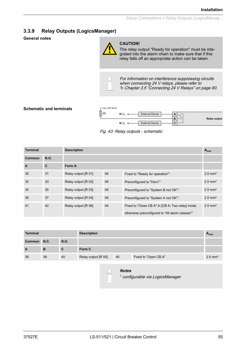
3.3.9 Relay Outputs (LogicsManager)
CAUTION!The relay output "Ready for operation" must be inte‐grated into the alarm chain to make sure that if thisrelay falls off an appropriate action can be taken.
For information on interference suppressing circuitswhen connecting 24 V relays, please refer toÄ Chapter 3.5 “Connecting 24 V Relays” on page 60.
Fig. 43: Relay outputs - schematic
Terminal Description Amax
Common N.O. A C Form A 30 31 Relay output [R 01] All Fixed to "Ready for operation"1 2.5 mm²
32 33 Relay output [R 02] All Preconfigured to "Horn"1 2.5 mm²
34 35 Relay output [R 03] All Preconfigured to "System B not OK"1 2.5 mm²
36 37 Relay output [R 04] All Preconfigured to "System A not OK"1 2.5 mm²
41 42 Relay output [R 06] All Fixed to "Close CB A" in [CB A: Two relay] mode
otherwise preconfigured to "All alarm classes"1
2.5 mm²
Terminal Description Amax
Common N.C. N.O. A B C Form C 38 39 40 Relay output [R 05] All Fixed to “Open CB A” 2.5 mm²
Notes1 configurable via LogicsManager
General notes
Schematic and terminals
Installation
Setup Connections > Relay Outputs (LogicsManag...
37527E LS-511/521 | Circuit Breaker Control 55
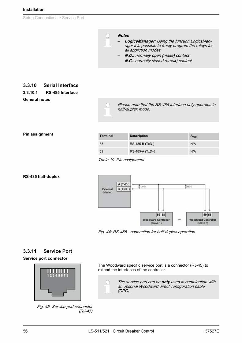
Notes– LogicsManager: Using the function LogicsMan‐
ager it is possible to freely program the relays forall appliction modes.
– N.O.: normally open (make) contactN.C.: normally closed (break) contact
3.3.10 Serial Interface3.3.10.1 RS-485 Interface
Please note that the RS-485 interface only operates inhalf-duplex mode.
Terminal Description Amax
58 RS-485-B (TxD-) N/A
59 RS-485-A (TxD+) N/A
Table 19: Pin assignment
Fig. 44: RS-485 - connection for half-duplex operation
3.3.11 Service Port
The Woodward specific service port is a connector (RJ-45) toextend the interfaces of the controller.
The service port can be only used in combination withan optional Woodward direct configuration cable(DPC).
General notes
Pin assignment
RS-485 half-duplex
Service port connector
Fig. 45: Service port connector(RJ-45)
Installation
Setup Connections > Service Port
37527ELS-511/521 | Circuit Breaker Control56
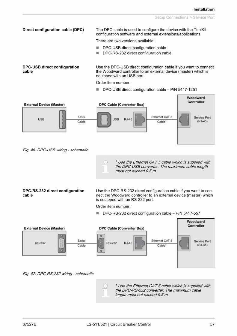
The DPC cable is used to configure the device with the ToolKitconfiguration software and external extensions/applications.There are two versions available:n DPC-USB direct configuration cablen DPC-RS-232 direct configuration cable
Use the DPC-USB direct configuration cable if you want to connectthe Woodward controller to an external device (master) which isequipped with an USB port.Order item number:n DPC-USB direct configuration cable – P/N 5417-1251
Fig. 46: DPC-USB wiring - schematic
1 Use the Ethernet CAT 5 cable which is supplied withthe DPC-USB converter. The maximum cable lengthmust not exceed 0.5 m.
Use the DPC-RS-232 direct configuration cable if you want to con‐nect the Woodward controller to an external device (master) whichis equipped with an RS-232 port.Order item number:n DPC-RS-232 direct configuration cable – P/N 5417-557
Fig. 47: DPC-RS-232 wiring - schematic
1 Use the Ethernet CAT 5 cable which is supplied withthe DPC-RS-232 converter. The maximum cablelength must not exceed 0.5 m.
Direct configuration cable (DPC)
DPC-USB direct configurationcable
DPC-RS-232 direct configurationcable
Installation
Setup Connections > Service Port
37527E LS-511/521 | Circuit Breaker Control 57
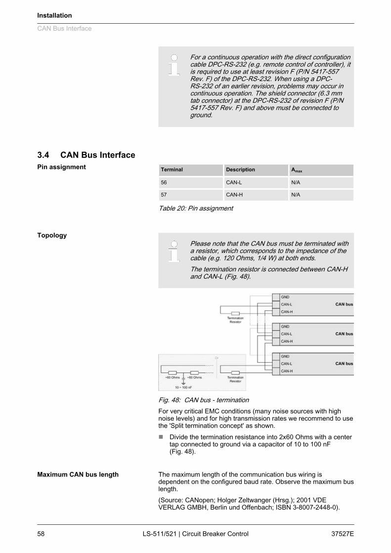
For a continuous operation with the direct configurationcable DPC-RS-232 (e.g. remote control of controller), itis required to use at least revision F (P/N 5417-557Rev. F) of the DPC-RS-232. When using a DPC-RS-232 of an earlier revision, problems may occur incontinuous operation. The shield connector (6.3 mmtab connector) at the DPC-RS-232 of revision F (P/N5417-557 Rev. F) and above must be connected toground.
3.4 CAN Bus InterfaceTerminal Description Amax
56 CAN-L N/A
57 CAN-H N/A
Table 20: Pin assignment
Please note that the CAN bus must be terminated witha resistor, which corresponds to the impedance of thecable (e.g. 120 Ohms, 1/4 W) at both ends.The termination resistor is connected between CAN-Hand CAN-L (Fig. 48).
Fig. 48: CAN bus - terminationFor very critical EMC conditions (many noise sources with highnoise levels) and for high transmission rates we recommend to usethe 'Split termination concept' as shown.n Divide the termination resistance into 2x60 Ohms with a center
tap connected to ground via a capacitor of 10 to 100 nF(Fig. 48).
The maximum length of the communication bus wiring isdependent on the configured baud rate. Observe the maximum buslength.(Source: CANopen; Holger Zeltwanger (Hrsg.); 2001 VDEVERLAG GMBH, Berlin und Offenbach; ISBN 3-8007-2448-0).
Pin assignment
Topology
Maximum CAN bus length
Installation
CAN Bus Interface
37527ELS-511/521 | Circuit Breaker Control58
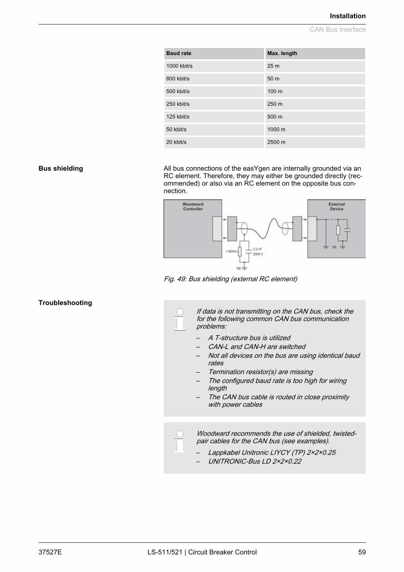
Baud rate Max. length
1000 kbit/s 25 m
800 kbit/s 50 m
500 kbit/s 100 m
250 kbit/s 250 m
125 kbit/s 500 m
50 kbit/s 1000 m
20 kbit/s 2500 m
All bus connections of the easYgen are internally grounded via anRC element. Therefore, they may either be grounded directly (rec‐ommended) or also via an RC element on the opposite bus con‐nection.
Fig. 49: Bus shielding (external RC element)
If data is not transmitting on the CAN bus, check thefor the following common CAN bus communicationproblems:– A T-structure bus is utilized– CAN-L and CAN-H are switched– Not all devices on the bus are using identical baud
rates– Termination resistor(s) are missing– The configured baud rate is too high for wiring
length– The CAN bus cable is routed in close proximity
with power cables
Woodward recommends the use of shielded, twisted-pair cables for the CAN bus (see examples).– Lappkabel Unitronic LIYCY (TP) 2×2×0.25– UNITRONIC-Bus LD 2×2×0.22
Bus shielding
Troubleshooting
Installation
CAN Bus Interface
37527E LS-511/521 | Circuit Breaker Control 59

3.5 Connecting 24 V Relays
NOTICE!Damage to adjacent electronic components due toinduced voltages– Implement protection circuits as detailed below.
Interferences in the interaction of all components may affect thefunction of electronic devices. One interference factor is disablinginductive loads, like coils of electromagnetic switching devices.When disabling such a device, high switch-off induced voltagesmay occur, which might destroy adjacent electronic devices orresult interference voltage pulses, which lead to functional faults,by capacitive coupling mechanisms.Since an interference-free switch-off is not possible without addi‐tional equipment, the relay coil is connected with an interferencesuppressing circuit.If 24 V (coupling) relays are used in an application, it is required toconnect a protection circuit to avoid interferences.
Fig. 50 shows the exemplary connection of a diode asan interference suppressing circuit.
Advantages and disadvantages of different interference sup‐pressing circuits are as follows:
Connection diagram Load current / voltage curve Advantages Disadvantages
Uncritical dimensioning
Lowest possible inducedvoltage
Very simple and reliable
High release delay
Uncritical dimensioning
High energy absorption
Very simple setup
Suitable for AC voltage
Reverse polarity protected
No attenuation below VVDR
HF attenuation by energystorage
Immediate shut-off limiting
Attenuation below limitingvoltage
Very suitable for AC voltage
Reverse polarity protected
Exact dimensioning required
Fig. 50: Protection circuit (example)
Installation
Connecting 24 V Relays
37527ELS-511/521 | Circuit Breaker Control60
4 ConfigurationAll parameters are assigned a unique parameter identificationnumber.The parameter identification number may be used to referenceindividual parameters listed in this manual.
This parameter identification number is also displayedin the ToolKit configuration screens next to the respec‐tive parameter.
4.1 Basic Setup4.1.1 Configure Language/Clock
The following parameters are used to set the unit language, thecurrent date and time, and the daylight saving time feature.
If an Asian language is configured, some parameterscreens may be displayed with an empty space at thebottom of the parameter list, which may be interpretedas an end of the list, although more parameters existand are displayed when scrolling down.
ID Parameter CL Setting range
[Default]
Description
1700 Language
(Set language)
0 selectable lan‐guages
[English]
The desired language for the unit display text is configured here.
1710 Hour 0 hour 0 to 23 h
[real-timeclock]
The hour of the clock time is set here.
Example
n 0 = 0th hour of the day (midnight).n 23 = 23rd hour of the day (11 pm).
1709 Minute 0 0 to 59 min
[real-timeclock]
The minute of the clock time is set here.
Example
n 0 = 0th minute of the hourn 59 = 59th minute of the hour
1708 Second 0 0 to 59 s
[real-timeclock]
The second of the clock time is set here.
General notes
Configuration
Basic Setup > Configure Language/Clock
37527E LS-511/521 | Circuit Breaker Control 61

ID Parameter CL Setting range
[Default]
Description
Example
n 0 = 0th second of the minuten 59 = 59th second of the minute
1698 Transfer timeto clock
0 Yes Adjusted time will be transfered to the unit.
No Adjusted time will be not transfered to the unit.
Notes
This parameter may only be configured using ToolKit.
1711 Day 0 day 1 to 31
[real-timeclock]
The day of the date is set here.
Example
n 1 = 1st day of the month.n 31 = 31st day of the month.
1712 Month 0 month 1 to 12
[real-timeclock]
The month of the date is set here.
Example
n 1 = 1st month of the year.n 12 = 12th month of the year.
1713 Year 0 year 0 to 99
[real-timeclock]
The year of the date is set here.
Example
n 0 = Year 2000n 99 = Year 2099
1699 Transfer dateto clock
0 Yes Adjusted date will be transfered to the unit.
No Adjusted date will be not transfered to the unit.
Notes
This parameter may only be configured using ToolKit.
4591 Daylightsaving time
2 The daylight saving time feature enables to automatically adjust the real-timeclock to local daylight saving time (DST) provisions. If daylight saving time isenabled, the real-time clock will automatically be advanced by one hour whenthe configured DST begin date and time is reached and falls back again byone hour when the configured DST end date and time is reached.
If the unit is used in the southern hemisphere, the DST function will beinverted automatically, if the DST begin month is later in the year than theDST end month.
On Daylight saving time is enabled.
[Off] Daylight saving time is disabled.
Configuration
Basic Setup > Configure Language/Clock
37527ELS-511/521 | Circuit Breaker Control62

ID Parameter CL Setting range
[Default]
Description
Notes
Do not change the time manually during the hour of the automatic timechange if DST is enabled to avoid a wrong time setting.
Events or alarms, which occur during this hour might have a wrong timestamp.
4594 DST begin time 2 0 to 23
[2]The real-time clock will be advanced by one hour when this time is reachedon the DST begin date.
Example
n 0 = 0th hour of the day (midnight)n 23 = 23rd hour of the day (11 pm)
Notes
This parameter is only displayed, if Daylight saving time (param‐eter 4591 Ä p. 62) is set to "On".
4598 DST beginweekday
2 Sunday to Sat‐urday
[Sunday]
The weekday for the DST begin date is configured here
Notes
This parameter is only displayed, if Daylight saving time (param‐eter 4591 Ä p. 62) is set to "On".
4592 DST begin nth.weekday
2 The order number of the weekday for the DST begin date is configured here.
1st DST starts on the 1st configured weekday of the DST begin month.
2nd DST starts on the 2nd configured weekday of the DST begin month.
3rd DST starts on the 3rd configured weekday of the DST begin month.
4th DST starts on the 4th configured weekday of the DST begin month.
[Last] DST starts on the last configured weekday of the DST begin month.
LastButOne DST starts on the last but one configured weekday of the DST begin month.
LastButTwo DST starts on the last but two configured weekday of the DST begin month.
LastButThree DST starts on the last but three configured weekday of the DST begin month.
Notes
This parameter is only displayed, if Daylight saving time (param‐eter 4591 Ä p. 62) is set to "On".
4593 DST beginmonth
2 1 to 12
[3]
The month for the DST begin date is configured here.
Example
n 1 = 1st month of the yearn 12 = 12th month of the year
Notes
This parameter is only displayed, if Daylight saving time (param‐eter 4591 Ä p. 62) is set to "On".
4597 DST end time 2 0 to 23
[3]
The real-time clock will fall back by one hour when this time is reached on theDST end date
Configuration
Basic Setup > Configure Language/Clock
37527E LS-511/521 | Circuit Breaker Control 63
ID Parameter CL Setting range
[Default]
Description
Example
n 0 = 0th hour of the day (midnight).n 23 = 23rd hour of the day (11 pm).
Notes
This parameter is only displayed, if Daylight saving time (param‐eter 4591 Ä p. 62) is set to "On".
4599 DST endweekday
2 Sunday to Sat‐urday
[Sunday]
The weekday for the DST end date is configured here
Notes
This parameter is only displayed, if Daylight saving time (param‐eter 4591 Ä p. 62) is set to "On".
4595 DST end nth.weekday
2 The order number of the weekday for the DST begin date is configured here.
1st DST ends on the 1st configured weekday of the DST begin month.
2nd DST ends on the 2nd configured weekday of the DST begin month.
3rd DST ends on the 3rd configured weekday of the DST begin month.
4th DST ends on the 4th configured weekday of the DST begin month.
[Last] DST ends on the last configured weekday of the DST begin month.
LastButOne DST ends on the last but one configured weekday of the DST begin month.
LastButTwo DST ends on the last but two configured weekday of the DST begin month.
LastButThree DST ends on the last but three configured weekday of the DST begin month.
Notes
This parameter is only displayed, if Daylight saving time (param‐eter 4591 Ä p. 62) is set to "On".
4596 DST endmonth
2 1 to 12
[10]
The month for the DST begin date is configured here.
Example
n 1 = 1st month of the yearn 12 = 12th month of the year
Notes
This parameter is only displayed, if Daylight saving time (param‐eter 4591 Ä p. 62) is set to "On".
If daylight saving time starts at 2:00 am on the 2nd Sunday inMarch and ends at 2:00 am on the 1st Sunday in November, theunit has to be configured like shown in Ä “Daylight saving time -configuration example” Table on page 64 to enable an automaticchange to daylight saving time and back to standard time.
ID Parameter Setting
4591 Daylight saving time On
4594 DST begin time 2
Example
Configuration
Basic Setup > Configure Language/Clock
37527ELS-511/521 | Circuit Breaker Control64
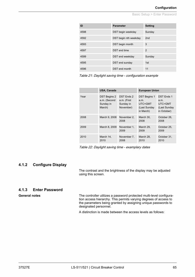
ID Parameter Setting
4598 DST begin weekday Sunday
4592 DST begin nth weekday 2nd
4593 DST begin month 3
4597 DST end time 2
4599 DST end weekday Sunday
4595 DST end sunday 1st
4596 DST end month 11
Table 21: Daylight saving time - configuration example
USA, Canada European Union
Year DST Begins 2a.m. (SecondSunday inMarch)
DST Ends 2a.m. (FirstSunday inNovember)
DST Begins 1a.m.UTC=GMT(Last Sundayin March)
DST Ends 1a.m.UTC=GMT(Last Sundayin October)
2008 March 9, 2008 November 2,2008
March 30,2008
October 26,2008
2009 March 8, 2009 November 1,2009
March 29,2009
October 25,2009
2010 March 14,2010
November 7,2008
March 28,2010
October 31,2010
Table 22: Daylight saving time - examplary dates
4.1.2 Configure DisplayThe contrast and the brightness of the display may be adjustedusing this screen.
4.1.3 Enter PasswordThe controller utilizes a password protected multi-level configura‐tion access hierarchy. This permits varying degrees of access tothe parameters being granted by assigning unique passwords todesignated personnel.A distinction is made between the access levels as follows:
General notes
Configuration
Basic Setup > Enter Password
37527E LS-511/521 | Circuit Breaker Control 65
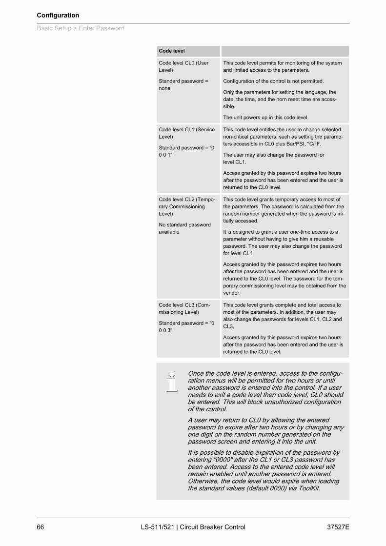
Code level Code level CL0 (UserLevel)
Standard password =none
This code level permits for monitoring of the systemand limited access to the parameters.
Configuration of the control is not permitted.
Only the parameters for setting the language, thedate, the time, and the horn reset time are acces‐sible.
The unit powers up in this code level.
Code level CL1 (ServiceLevel)
Standard password = "00 0 1"
This code level entitles the user to change selectednon-critical parameters, such as setting the parame‐ters accessible in CL0 plus Bar/PSI, °C/°F.
The user may also change the password forlevel CL1.
Access granted by this password expires two hoursafter the password has been entered and the user isreturned to the CL0 level.
Code level CL2 (Tempo‐rary CommissioningLevel)
No standard passwordavailable
This code level grants temporary access to most ofthe parameters. The password is calculated from therandom number generated when the password is ini‐tially accessed.
It is designed to grant a user one-time access to aparameter without having to give him a reusablepassword. The user may also change the passwordfor level CL1.
Access granted by this password expires two hoursafter the password has been entered and the user isreturned to the CL0 level. The password for the tem‐porary commissioning level may be obtained from thevendor.
Code level CL3 (Com‐missioning Level)
Standard password = "00 0 3"
This code level grants complete and total access tomost of the parameters. In addition, the user mayalso change the passwords for levels CL1, CL2 andCL3.
Access granted by this password expires two hoursafter the password has been entered and the user isreturned to the CL0 level.
Once the code level is entered, access to the configu‐ration menus will be permitted for two hours or untilanother password is entered into the control. If a userneeds to exit a code level then code level, CL0 shouldbe entered. This will block unauthorized configurationof the control.A user may return to CL0 by allowing the enteredpassword to expire after two hours or by changing anyone digit on the random number generated on thepassword screen and entering it into the unit.It is possible to disable expiration of the password byentering "0000" after the CL1 or CL3 password hasbeen entered. Access to the entered code level willremain enabled until another password is entered.Otherwise, the code level would expire when loadingthe standard values (default 0000) via ToolKit.
Configuration
Basic Setup > Enter Password
37527ELS-511/521 | Circuit Breaker Control66

The current code level is indicated by the corresponding numericvalue (e.g. “Code level display” : “1” ) in the configuration menuscreens. The value indicates that all parameters of a higher codelevel are "locked".
ID Parameter CL Setting range
[Default]
Description
10400 Password dis‐play
0 0000 to 9999
[randomnumber]
The password for configuring the control via the front panel must be enteredhere.
10405 Code level dis‐play
0 (display only)
[0]
This value displays the code level, which is currently enabled for access viathe front panel display.
10402 Password forCAN interface1
0 0000 to 9999
[randomnumber]
The password for configuring the control via the CAN interface #1 must beentered here.
10407 Code levelCAN interface1
0 (display only)
[0]
This value displays the code level, which is currently enabled for access viathe CAN interface #1.
10401 Password forserial interface1
0 0000 to 9999
[randomnumber]
The password for configuring the control via RS-232 serial interface #1 mustbe entered here.
10406 Code levelserial interface1
0 (display only)
[0]
This value displays the code level, which is currently enabled for access viaRS-232 serial interface #1.
10430 Password forserial interface2
2 0000 to 9999
[randomnumber]
The password for configuring the control via RS-485 serial interface #1 mustbe entered here..
10420 Code levelserial interface2
0 (display only)
[0]
This value displays the code level, which is currently enabled for access viaRS-485 serial interface #1.
4.1.4 System ManagementID Parameter CL Setting range
[Default]
Description
1702 Device number 2 33 to 64
[33]
A unique address is assigned to the control though this parameter. Thisunique address permits the controller to be correctly identified on the CANbus. The address assigned to the controller may only be used once.
All other bus addresses are calculated on the number entered in this param‐eter.
Notes
The unit must be restarted after changing the device number to ensure properoperation.
No access in the application modes and .
4556 Configure dis‐play backlight
2 On The display backlight is always enabled.
Off The display backlight is always disabled.
Code level display
Configuration
Basic Setup > System Management
37527E LS-511/521 | Circuit Breaker Control 67
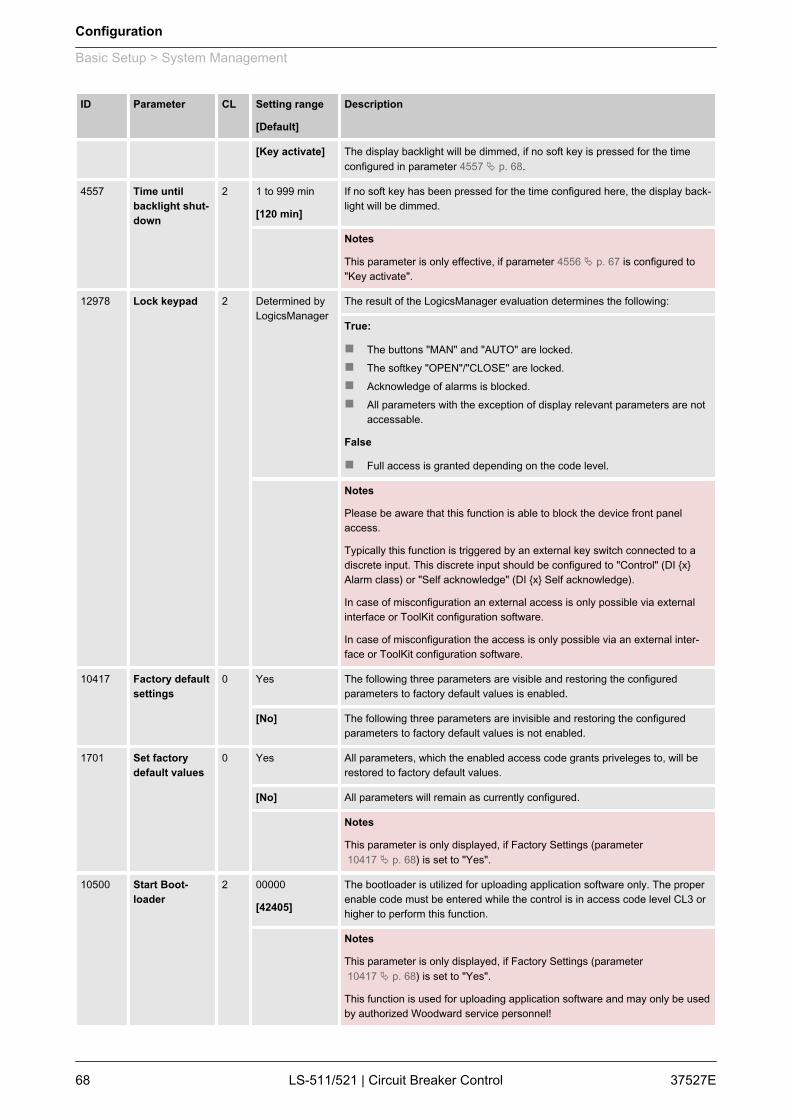
ID Parameter CL Setting range
[Default]
Description
[Key activate] The display backlight will be dimmed, if no soft key is pressed for the timeconfigured in parameter 4557 Ä p. 68.
4557 Time untilbacklight shut‐down
2 1 to 999 min
[120 min]
If no soft key has been pressed for the time configured here, the display back‐light will be dimmed.
Notes
This parameter is only effective, if parameter 4556 Ä p. 67 is configured to"Key activate".
12978 Lock keypad 2 Determined byLogicsManager
The result of the LogicsManager evaluation determines the following:
True:
n The buttons "MAN" and "AUTO" are locked.n The softkey "OPEN"/"CLOSE" are locked.n Acknowledge of alarms is blocked.n All parameters with the exception of display relevant parameters are not
accessable.
False
n Full access is granted depending on the code level.
Notes
Please be aware that this function is able to block the device front panelaccess.
Typically this function is triggered by an external key switch connected to adiscrete input. This discrete input should be configured to "Control" (DI {x}Alarm class) or "Self acknowledge" (DI {x} Self acknowledge).
In case of misconfiguration an external access is only possible via externalinterface or ToolKit configuration software.
In case of misconfiguration the access is only possible via an external inter‐face or ToolKit configuration software.
10417 Factory defaultsettings
0 Yes The following three parameters are visible and restoring the configuredparameters to factory default values is enabled.
[No] The following three parameters are invisible and restoring the configuredparameters to factory default values is not enabled.
1701 Set factorydefault values
0 Yes All parameters, which the enabled access code grants priveleges to, will berestored to factory default values.
[No] All parameters will remain as currently configured.
Notes
This parameter is only displayed, if Factory Settings (parameter 10417 Ä p. 68) is set to "Yes".
10500 Start Boot‐loader
2 00000
[42405]
The bootloader is utilized for uploading application software only. The properenable code must be entered while the control is in access code level CL3 orhigher to perform this function.
Notes
This parameter is only displayed, if Factory Settings (parameter 10417 Ä p. 68) is set to "Yes".
This function is used for uploading application software and may only be usedby authorized Woodward service personnel!
Configuration
Basic Setup > System Management
37527ELS-511/521 | Circuit Breaker Control68

ID Parameter CL Setting range
[Default]
Description
1706 Clear eventlog 2 Yes The event history will be cleared.
[No] The event history will not be cleared.
Notes
This parameter is only displayed, if Factory Settings (parameter 10417 Ä p. 68) is set to "Yes".
4.1.5 Password System
The following passwords grant varying levels of accessto the parameters.Each individual password can be used to access theappropriate configuration level through multiple accessmethods and communication protocols (via the frontpanel, via serial RS-232/485 interface, and via theCAN bus).
ID Parameter CL Setting range
[Default]
Description
10415 Basic codelevel
1 1 to 9999
[-]
The password for the code level "Service" is defined in this parameter.
Refer to Ä Chapter 4.1.3 “Enter Password” on page 65 for default values.
10413 Commis‐sioning codelevel
3 1 to 9999
[-]
The password for the code level "Commission" is defined in this parameter.
Refer to Ä Chapter 4.1.3 “Enter Password” on page 65 for default values.
10414 Commis‐sioning codelevel
3 1 to 9999
[-]
The algorithm for calculating the password for the code level "TemporaryCommissioning" is defined in this parameter.
10412 Temp. super‐comm. levelcode
5 1 to 9999
[-]
The algorithm for calculating the password for the code level "TemporarySupercommissioning" is defined in this parameter.
10411 Supercommis‐sioning levelcode
5 1 to 9999
[-]
The password for the code level "Supercommissioning" is defined in thisparameter.
Refer to Ä Chapter 4.1.3 “Enter Password” on page 65 for default values.
General notes
Configuration
Basic Setup > Password System
37527E LS-511/521 | Circuit Breaker Control 69
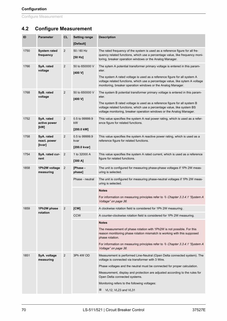
4.2 Configure MeasurementID Parameter CL Setting range
[Default]
Description
1750 System ratedfrequency
2 50 / 60 Hz
[50 Hz]
The rated frequency of the system is used as a reference figure for all fre‐quency related functions, which use a percentage value, like frequency moni‐toring, breaker operation windows or the Analog Manager.
1766 SyA. ratedvoltage
2 50 to 650000 V
[400 V]
The sytem A potential transformer primary voltage is entered in this param‐eter.
The system A rated voltage is used as a reference figure for all system Avoltage related functions, which use a percentage value, like sytem A voltagemonitoring, breaker operation windows or the Analog Manager.
1768 SyB. ratedvoltage
2 50 to 650000 V
[400 V]
The system B potential transformer primary voltage is entered in this param‐eter.
The system B rated voltage is used as a reference figure for all system Bvoltage related functions, which use a percentage value, like system BSvoltage monitoring, breaker operation windows or the Analog Manager.
1752 SyA. ratedactive power[kW]
2 0.5 to 99999.9kW
[200.0 kW]
This value specifies the system A real power rating, which is used as a refer‐ence figure for related functions.
1758 SyA. ratedreact. power[kvar]
2 0.5 to 99999.9kvar
[200.0 kvar]
This value specifies the system A reactive power rating, which is used as areference figure for related functions.
1754 SyA. rated cur‐rent
2 1 to 32000 A
[300 A]
This value specifies the system A rated current, which is used as a referencefigure for related functions.
1858 1Ph2W voltagemeasuring
2 [Phase -phase]
The unit is configured for measuring phase-phase voltages if 1Ph 2W meas‐uring is selected.
Phase - neutral The unit is configured for measuring phase-neutral voltages if 1Ph 2W meas‐uring is selected.
Notes
For information on measuring principles refer to Ä Chapter 3.3.4.1 “System AVoltage” on page 36.
1859 1Ph2W phaserotation
2 [CW] A clockwise rotation field is considered for 1Ph 2W measuring .
CCW A counter-clockwise rotation field is considered for 1Ph 2W measuring.
Notes
The measurement of phase rotation with 1Ph2W is not possible. For thisreason montitoring phase rotation mismatch is working with this supposedphase rotation.
For information on measuring principles refer to Ä Chapter 3.3.4.1 “System AVoltage” on page 36.
1851 SyA. voltagemeasuring
2 3Ph 4W OD Measurement is performed Line-Neutral (Open Delta connected system). Thevoltage is connected via transformer with 3 Wire.
Phase voltages and the neutral must be connected for proper calculation.
Measurement, display and protection are adjusted according to the rules forOpen Delta connected systems.
Monitoring refers to the following voltages:
n VL12, VL23 and VL31
Configuration
Configure Measurement
37527ELS-511/521 | Circuit Breaker Control70
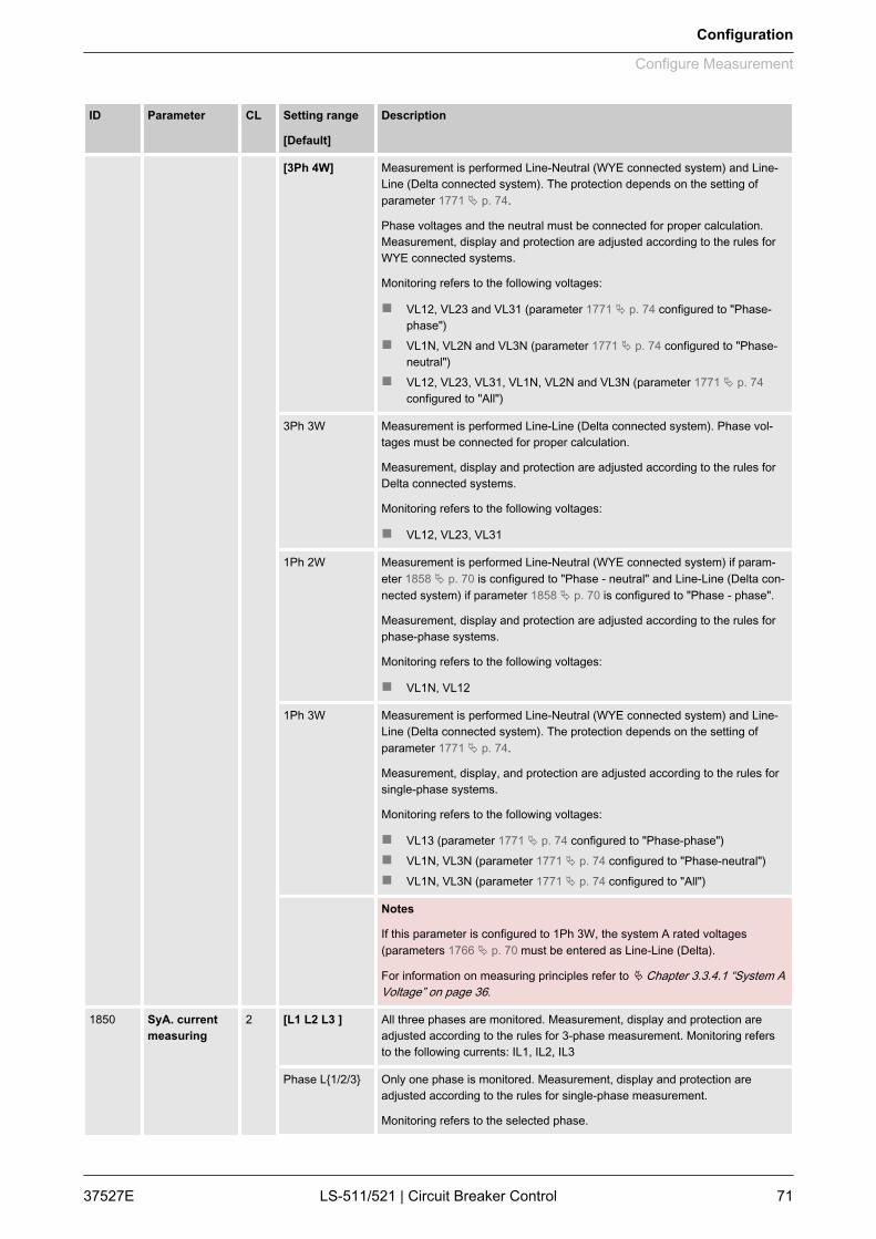
ID Parameter CL Setting range
[Default]
Description
[3Ph 4W] Measurement is performed Line-Neutral (WYE connected system) and Line-Line (Delta connected system). The protection depends on the setting ofparameter 1771 Ä p. 74.
Phase voltages and the neutral must be connected for proper calculation.Measurement, display and protection are adjusted according to the rules forWYE connected systems.
Monitoring refers to the following voltages:
n VL12, VL23 and VL31 (parameter 1771 Ä p. 74 configured to "Phase-phase")
n VL1N, VL2N and VL3N (parameter 1771 Ä p. 74 configured to "Phase-neutral")
n VL12, VL23, VL31, VL1N, VL2N and VL3N (parameter 1771 Ä p. 74configured to "All")
3Ph 3W Measurement is performed Line-Line (Delta connected system). Phase vol‐tages must be connected for proper calculation.
Measurement, display and protection are adjusted according to the rules forDelta connected systems.
Monitoring refers to the following voltages:
n VL12, VL23, VL31
1Ph 2W Measurement is performed Line-Neutral (WYE connected system) if param‐eter 1858 Ä p. 70 is configured to "Phase - neutral" and Line-Line (Delta con‐nected system) if parameter 1858 Ä p. 70 is configured to "Phase - phase".
Measurement, display and protection are adjusted according to the rules forphase-phase systems.
Monitoring refers to the following voltages:
n VL1N, VL12
1Ph 3W Measurement is performed Line-Neutral (WYE connected system) and Line-Line (Delta connected system). The protection depends on the setting ofparameter 1771 Ä p. 74.
Measurement, display, and protection are adjusted according to the rules forsingle-phase systems.
Monitoring refers to the following voltages:
n VL13 (parameter 1771 Ä p. 74 configured to "Phase-phase")n VL1N, VL3N (parameter 1771 Ä p. 74 configured to "Phase-neutral")n VL1N, VL3N (parameter 1771 Ä p. 74 configured to "All")
Notes
If this parameter is configured to 1Ph 3W, the system A rated voltages(parameters 1766 Ä p. 70 must be entered as Line-Line (Delta).
For information on measuring principles refer to Ä Chapter 3.3.4.1 “System AVoltage” on page 36.
1850 SyA. currentmeasuring
2 [L1 L2 L3 ] All three phases are monitored. Measurement, display and protection areadjusted according to the rules for 3-phase measurement. Monitoring refersto the following currents: IL1, IL2, IL3
Phase L{1/2/3} Only one phase is monitored. Measurement, display and protection areadjusted according to the rules for single-phase measurement.
Monitoring refers to the selected phase.
Configuration
Configure Measurement
37527E LS-511/521 | Circuit Breaker Control 71

ID Parameter CL Setting range
[Default]
Description
Notes
This parameter is only effective if system A voltage measuring (param‐eter 1851 Ä p. 70) is configured to "3Ph 4W" or "3Ph 3W".
For information on measuring principles refer to Ä Chapter 3.3.4.1 “System AVoltage” on page 36.
1853 SyB. voltagemeasuring
2 [3Ph 4W] Measurement is performed Line-Neutral (WYE connected system) and Line-Line (Delta connected system). The protection depends on the setting ofparameter 1770 Ä p. 96.
Phase voltages and the neutral must be connected for proper calculation.Measurement, display and protection are adjusted according to the rules forWYE connected systems.
Monitoring refers to the following voltages:
n VL12, VL23 and VL31 (parameter 1770 Ä p. 96 configured to "Phase-phase")
n VL1N, VL2N and VL3N (parameter 1770 Ä p. 96 configured to "Phase-neutral")
3Ph 3W Measurement is performed Line-Line (Delta connected system). Phase vol‐tages must be connected for proper calculation.
Measurement, display and protection are adjusted according to the rules forDelta connected systems.
Monitoring refers to the following voltages:
n VL12, VL23, VL31
1Ph 2W Measurement is performed Line-Neutral (WYE connected system) if param‐eter 1858 Ä p. 70 is configured to "Phase - neutral" and Line-Line (Delta con‐nected system) if parameter 1858 Ä p. 70 is configured to "Phase - phase".
Measurement, display and protection are adjusted according to the rules forphase-phase systems.
Monitoring refers to the following voltages:
n VL1N, VL12
1Ph 3W Measurement is performed Line-Neutral (WYE connected system) and Line-Line (Delta connected system).
The protection depends on the setting of parameter 1770 Ä p. 96. Measure‐ment, display, and protection are adjusted according to the rules for single-phase systems.
Monitoring refers to the following voltages:
n VL13 (parameter 1770 Ä p. 96 configured to "Phase-phase")n VL1N, VL3N (parameter 1770 Ä p. 96 configured to "Phase-neutral")
Notes
If this parameter is configured to 1Ph 3W, the system B rated voltages(parameter 1768 Ä p. 70) must be entered as Line-Line (Delta).
For information on measuring principles refer to Ä Chapter 3.3.4.1 “System AVoltage” on page 36.
Configuration
Configure Measurement
37527ELS-511/521 | Circuit Breaker Control72

4.2.1 Configure TransformerThis controller is available in two different hardware versions witheither 1A [../1] or 5A [../5] current transformer inputs.The setpoints for specific parameters will differ depending upon thehardware version, indicated on the data plate.n [1] LS-5xx-1 = Current transformer with ../1 A rated currentn [5] LS-5xx-5 = Current transformer with ../5 A rated current
ID Parameter CL Setting range
[Default]
Description
1801 SyA. PT pri‐mary ratedvoltage
2 50 to 650000 V
[400 V]
Some applications may require the use of potential transformers to facilitatemeasuring the voltages. The rating of the primary side of the potential trans‐former must be entered into this parameter.
If the application does not require potential transformers at sytem A (i.e. thevoltage is 480 V or less), then this voltage will be entered into this parameter.
1800 SyA. PT secon‐dary ratedvoltage
2 50 to 480 V
[400 V]
Some applications may require the use of potential transformers to facilitatemeasuring the voltages. The rating of the secondary side of the potentialtransformer must be entered into this parameter.
If the application does not require potential transformers at system A (i.e. thevoltage is 480 V or less), then this voltage will be entered into this parameter.
n Rated voltage: 120 Vac (this parameter configured between 50 and130 V)System A voltage: Terminals 14/16/18/20
n Rated voltage: 480 Vac (this parameter configured between 131 and480 V)System A voltage: Terminals 15/17/19/21
Notes
WARNING: Only connect the measured voltage to either the 120 Vac or the480 Vac inputs. Do not connect both sets of inputs to the measured system.
The control unit is equipped with dual voltage measuring inputs. The voltagerange of these measurement inputs is dependent upon input terminals areused. This value refers to the secondary voltages of the potential trans‐formers, which are directly connected to the control unit.
1806 SyA. CT pri‐mary rated cur‐rent
2 1 to 32000 A/x
[500 A/x]
The input of the current transformer ratio is necessary for the indication andcontrol of the actual monitored value.
The current transformers ratio should be selected so that at least 60 % of thesecondary current rating can be measured when the monitored system is at100 % of operating capacity (i.e. at 100 % of system capacity a 5 A CT shouldoutput 3 A).
If the current transformers are sized so that the percentage of the output islower, the loss of resolution may cause inaccuracies in the monitoring andcontrol functions and affect the functionality of the control.
1804 SyB. PT pri‐mary ratedvoltage
2 50 to 650000 V
[400 V]
Some applications may require the use of potential transformers to facilitatemeasuring the voltages to be monitored. The rating of the primary side of thepotential transformer must be entered into this parameter.
Notes
If the application does not require potential transformers (i.e. the measuredvoltage is 480 V or less), then the measured voltage will be entered into thisparameter.
General notes
Configuration
Configure Measurement > Configure Transformer
37527E LS-511/521 | Circuit Breaker Control 73

ID Parameter CL Setting range
[Default]
Description
1803 SyB. PT secon‐dary ratedvoltage
2 50 to 480 V
[400 V]
Some applications may require the use of potential transformers to facilitatemeasuring the mains voltages. The rating of the secondary side of the poten‐tial transformer must be entered into this parameter.
If the application does not require potential transformers (i.e. the measuredvoltage is 480 V or less), then the measured voltage will be entered into thisparameter.
n Rated voltage: 120 Vac (this parameter configured between 50 and130 V)System B voltage: Terminals 22/24/26/28
n Rated voltage: 480 Vac (this parameter configured between 131 and480 V)System B Voltage: Terminals 23/25/27/29
Notes
WARNING: Only connect the measured voltage to either the 120 Vac or the480 Vac inputs. Do not connect both sets of inputs to the measured system.
The control is equipped with dual voltage measuring inputs. The voltagerange of these measurement inputs is dependent upon input terminals areused. This value refers to the secondary voltages of the potential trans‐formers, which are directly connected to the control.
4.3 Configure Monitoring4.3.1 System AID Parameter CL Setting range
[Default]
Description
1771 SyA. voltagemonitoring
2 The unit can either monitor the wye voltages (phase-neutral) or the delta vol‐tages (phase-phase). The monitoring of the wye voltage is above all neces‐sary to avoid earth-faults in a compensated or isolated network resulting inthe tripping of the voltage protection.
[Phase -phase]
The phase-phase voltage will be monitored and all subsequent parametersconcerning voltage monitoring "system A" are referred to this value (VL-L).
Phase - neutral The phase-neutral voltage will be monitored and all subsequent parametersconcerning voltage monitoring "system A" are referred to this value (VL-N).
All The phase-phase and phase-neutral voltage will be monitored and all subse‐quent parameters concerning voltage monitoring "system A" are referred tothis value (VL-L & VL-N).
This setting is only effective if "SyA. voltage measuring" (parameter1851 Ä p. 70) is configured to "3Ph 4W".
Configuration
Configure Monitoring > System A
37527ELS-511/521 | Circuit Breaker Control74

ID Parameter CL Setting range
[Default]
Description
Notes
WARNING: This parameter influences the protective functions.
Please be aware that if "SyA. voltage monitoring" (parameter 1771 Ä p. 74) isconfigured to "All" and the function Ä Chapter 4.3.1.12 “System A VoltageIncrease” on page 91 is used, that this function only monitors "Phase - neu‐tral".
2801 Mains settlingtime
2 0 to 9999 s
[20 s]
To end the emergency operation, the monitored mains must be within theconfigured operating parameters without interruption for the minimum periodof time set with this parameter without interruption.
This parameter permits delaying the switching of the load from the generatorto the mains.
The display indicates "Mains settling" during this time.
4.3.1.1 System A Operating Voltage / Frequency
If system A is configured and wired for mains, thesystem A operating voltage/frequency parameters canbe used to trigger mains failure conditions and activatean emergency run.The system A values must be within these ranges tosynchronize the CBA.– It is recommended to configure the operating limits
within the monitoring limits.
If the system A rated voltage is 400 V, the upper voltage limit is110 % (of the system A rated voltage, i.e. 440 V), and the hyste‐resis for the upper voltage limit is 5 % (of the mains rated voltage,i.e. 20 V), the system A voltage will be considered as being out ofthe operating limits as soon as it exceeds 440 V and will be consid‐ered as being within the operating limits again as soon as it fallsbelow 420 V (440 V – 20 V).If the rated system frequency is 50 Hz, the lower frequency limit is90 % (of the rated system frequency, i.e. 45 Hz), and the hyste‐resis for the lower frequency limit is 5 % (of the rated system fre‐quency, i.e. 2.5 Hz), the mains frequency will be considered asbeing out of the operating limits as soon as it falls below 45 Hz andwill be considered as being within the operating limits again assoon as it exceeds 47.5 Hz (45 Hz + 2.5 Hz).
General notes
Example
Configuration
Configure Monitoring > System A > System A Operating Voltag...
37527E LS-511/521 | Circuit Breaker Control 75

ID Parameter CL Setting range
[Default]
Description
5810 Upper voltagelimit
2 100 to 150 %
[110 %]
The maximum permissible positive deviation of the system A voltage from thesystem A rated voltage (parameter 1768 Ä p. 70) is configured here.
This value may be used as a voltage limit switch. The conditional state of thisswitch may be used as a command variable for the LogicsManager (02.09).
5814 Hysteresisupper voltagelimit
2 0 to 50 %
[2 %]
If the system A voltage has exceeded the limit configured in parameter5810 Ä p. 76, the voltage must fall below the limit and the value configuredhere, to be considered as being within the operating limits again.
5811 Lower voltagelimit
2 50 to 100 %
[90 %]
The maximum permissible negative deviation of the system A voltage fromthe system A rated voltage (parameter 1768 Ä p. 70) is configured here.
This value may be used as a voltage limit switch. The conditional state of thisswitch may be used as a command variable for the LogicsManager (02.09).
5815 Hysteresislower voltagelimit
2 0 to 50 %
[2 %]
If the system A voltage has fallen below the limit configured in parameter5811 Ä p. 76, the voltage must exceed the limit and the value configuredhere, to be considered as being within the operating limits again.
5812 Upper fre‐quency limit
2 100.0 to 150.0%
[105.0 %]
The maximum permissible positive deviation of the system A frequency fromthe rated system frequency (parameter 1750 Ä p. 70) is configured here.
This value may be used as a frequency limit switch. The conditional state ofthis switch may be used as a command variable for the LogicsManager(02.10).
5816 Hysteresisupper fre‐quency limit
2 0 to 50 %
[0.5 %]
If the system A frequency has exceeded the limit configured in parameter5812 Ä p. 76, the frequency must fall below the limit and the value configuredhere, to be considered as being within the operating limits again.
5813 Lower fre‐quency limit
2 50.0 to 100.0 %
[95.0 %]
The maximum permissible negative deviation of the system A frequency fromthe rated system frequency (parameter 1750 Ä p. 70) is configured here.
This value may be used as a frequency limit switch. The conditional state ofthis switch may be used as a command variable for the LogicsManager(02.10).
5817 Hysteresislower fre‐quency limit
2 0 to 50 %
[0.5 %]
If the system A frequency has fallen below the limit configured in parameter5811 Ä p. 76, the frequemcy must exceed the limit and the value configuredhere, to be considered as being within the operating limits again.
4.3.1.2 System A DecouplingThe system A decoupling function is intended for use in a mainsparallel operation and monitors a series of subordinate mains pro‐tection thresholds. If a threshold is exceeded, the LS-5 initiates abreaker opening and separates the system B from the mains at thedefined breaker.The following thresholds are monitored:n Overfrequency level 1 (Ä Chapter 4.3.1.3 “System A Overfre‐
quency (Levels 1 & 2) ANSI# 81O” on page 78)n Overfrequency level 2 (Ä Chapter 4.3.1.3 “System A Overfre‐
quency (Levels 1 & 2) ANSI# 81O” on page 78)n Underfrequency level 1 (Ä Chapter 4.3.1.4 “System A Under‐
frequency (Level 1 & 2) ANSI# 81U” on page 79)n Underfrequency level 2 Ä Chapter 4.3.1.4 “System A Underfre‐
quency (Level 1 & 2) ANSI# 81U” on page 79()
General notes
Configuration
Configure Monitoring > System A > System A Decoupling
37527ELS-511/521 | Circuit Breaker Control76
n Overvoltage level 1 if parameterized for decoupling(Ä Chapter 4.3.1.5 “System A Overvoltage (Level 1 & 2)ANSI# 59” on page 80)
n Overvoltage level 2 (Ä Chapter 4.3.1.5 “System A Overvoltage(Level 1 & 2) ANSI# 59” on page 80)
n Undervoltage level 1 if parameterized (Ä Chapter 4.3.1.6“System A Undervoltage (Level 1 & 2) ANSI# 27” on page 82)
n Undervoltage level 2 (Ä Chapter 4.3.1.6 “System A Under‐voltage (Level 1 & 2) ANSI# 27” on page 82)
n Phase shift or df/dt (Ä Chapter 4.3.1.8 “Phase Shift”on page 85)
n Voltage increase if parameterized for decoupling(Ä Chapter 4.3.1.12 “System A Voltage Increase” on page 91)
If one of these protective functions is triggered, the display indi‐cates "SyA. decoupling" (the logical command variable "07.25" willbe enabled) and an active level 2 alarm.
The decoupling function is optimized on the relayoutput "CBA open". In case of using a free relay outputin conjunction with the command variable 07.25 anadditional delay time of up to 20 ms must be consid‐ered.
ID Parameter CL Setting range
[Default]
Description
12942 Enable SyA.decoupling
2 Determined byLogicsManager
If LogicsManager 24.31 is true, decoupling is "On".
Notes
For information on the LogicsManager and its default settings seeÄ Chapter 9.3.1 “LogicsManager Overview” on page 299.
3058 Change of fre‐quency
2 Off Change of frequency is not monitored.
[Ph. shift] Change of frequency is monitored on phase shift.
df/dt (ROCOF) Change of frequency is monitored on df/dt.
3111 Alarm class 2 A/B/C/D/E/F/Control
[B]
Each limit may be assigned an independent alarm class that specifies whataction should be taken when the limit is surpassed.
For additional information refer to Ä Chapter 9.4.1 “Alarm Classes”on page 328.
3112 Self acknowl‐edge
2 Yes The control unit automatically clears the alarm if the fault condition is nolonger detected.
[No] The control unit does not automatically reset the alarm when the fault condi‐tion is no longer detected.
The alarm must be acknowledged and reset by manually pressing the appro‐priate buttons or by activating the LogicsManager output "External acknowl‐edgement" (via a discrete input or via an interface).
Configuration
Configure Monitoring > System A > System A Decoupling
37527E LS-511/521 | Circuit Breaker Control 77
4.3.1.3 System A Overfrequency (Levels 1 & 2) ANSI# 81OThere are two overfrequency alarm levels available in the control.Both alarms are definite time alarms and are illustrated in the figurebelow. The figure diagrams a frequency trend and the associatedpickup times and length of the alarms. Monitoring of the frequencyis accomplished in two steps.
If this protective function is triggered, the display indi‐cates "SyA. overfrequency 1" or "SyA. overfrequency 2" and the logical command variable "07.06" or"07.07" will be enabled.
Refer to Ä Chapter 9.1.1 “Triggering Characteristics” on page 241for the triggering characteristic of this monitoring function.
The system A overfrequency Level 2 limit configurationparameters are located below the "SyA. decoupling"function menu on the display.
ID Parameter CL Setting range
[Default]
Description
2850
2856
Monitoring
(Limit 1/Limit 2)
2 [On]Overfrequency monitoring is carried out according to the following parame‐ters. Monitoring is performed at two levels. Both values may be configuredindependent from each other (prerequisite: Level 1 limit < limit 2).
Off Monitoring is disabled for Level 1 limit and/or Level 2 limit.
2854
2860
Limit
(Limit 1/Limit 2)
2 100.0 to 130.0%
2854: [100.4 %]
2860: [102.0 %]
The percentage values that are to be monitored for each threshold limit aredefined here.
If this value is reached or exceeded for at least the delay time without inter‐ruption, the action specified by the alarm class is initiated.
Notes
This value refers to the System rated frequency (parameter 1750 Ä p. 70).
2855
2561
Delay
(Limit 1/Limit 2)
2 0.02 to 99.99 s
[0.06 s]
If the monitored system A frequency value exceeds the threshold value forthe delay time configured here, an alarm will be issued.
Notes
If the monitored frequency falls below the threshold (minus the hysteresis)before the delay expires the time will be reset.
2851
2857
Alarm class
(Limit 1/Limit 2)
2 Class A/B/C/D/E/F/Control
2851: [A]
2857: [B]
Each limit may be assigned an independent alarm class that specifies whataction should be taken when the limit is surpassed.
Notes
For additional information refer to Ä Chapter 9.4.1 “Alarm Classes”on page 328
2852
2858
Self acknowl‐edge
(Limit 1/Limit 2)
2 Yes The control unit automatically clears the alarm if the fault condition is nolonger detected.
General notes
Configuration
Configure Monitoring > System A > System A Overfrequency (L...
37527ELS-511/521 | Circuit Breaker Control78

ID Parameter CL Setting range
[Default]
Description
[No] The control unit does not automatically reset the alarm when the fault condi‐tion is no longer detected.
The alarm must be acknowledged and reset by manually pressing the appro‐priate buttons or by activating the LogicsManager output "External acknowl‐edgement" (via a discrete input or via an interface).
2853
2859
Monitoringlockable
(Limit 1/Limit 2)
2 Yes Monitoring for fault conditions is only performed if "Lock Monitoring Status24.40" is false.
[No] Monitoring for this fault condition is continuously enabled regardless of "LockMonitoring Status 24.40".
4.3.1.4 System A Underfrequency (Level 1 & 2) ANSI# 81UThere are two underfrequency alarm levels available in the control.Both alarms are definite time alarms and are illustrated in the figurebelow. The figure diagrams a frequency trend and the associatedpickup times and length of the alarms. Monitoring of the frequencyis performed in two steps.
If this protective function is triggered, the display indi‐cates "SyA. underfrequency 1" or "SyA. underfre‐quency 2" and the logical command variable "07.08"or "07.09" will be enabled.
Refer to Ä Chapter 9.1.1 “Triggering Characteristics” on page 241for the triggering characteristic of this monitoring function.
The system A underfrequency Level 2 limit configura‐tion parameters are located below the "SyA. decou‐pling" function menu on the display.
ID Parameter CL Setting range
[Default]
Description
2900
2906
Monitoring
(Limit 1/Limit 2)
2 [On] Underfrequency monitoring is carried out according to the following parame‐ters. Monitoring is performed at two levels. Both values may be configuredindependent from each other (prerequisite: Level 1 limit > limit 2).
Off Monitoring is disabled for Level 1 limit and/or Level 2 limit.
2904
2910
Limit
(Limit 1/Limit 2)
2 50.0 to 130.0 %
2904: [99.6 %]
2910: [98.0 %]
The percentage values that are to be monitored for each threshold limit aredefined here.
If this value is reached or exceeded for at least the delay time without inter‐ruption, the action specified by the alarm class is initiated.
Notes
This value refers to the System rated frequency (parameter 1750 Ä p. 70).
2905
2911
Delay
(Limit 1/Limit 2)
2 0.02 to 99.99 s
2905: [1.50 s]
2911: [0.06 s]
If the monitored frequency value falls below the threshold value for the delaytime configured here, an alarm will be issued.
General notes
Configuration
Configure Monitoring > System A > System A Underfrequency (L...
37527E LS-511/521 | Circuit Breaker Control 79
ID Parameter CL Setting range
[Default]
Description
Notes
If the monitored frequency falls below the threshold (plus the hysteresis)before the delay expires the time will be reset.
2901
2907
Alarm class
(Limit 1/Limit 2)
2 Class A/B/C/D/E/F/Control
2901: [A]
2907: [B]
Each limit may be assigned an independent alarm class that specifies whataction should be taken when the limit is surpassed.
Notes
For additional information refer to Ä Chapter 9.4.1 “Alarm Classes”on page 328
2902
2908
Self acknowl‐edge
(Limit 1/Limit 2)
2 Yes The control unit automatically clears the alarm if the fault condition is nolonger detected.
[No] The control unit does not automatically reset the alarm when the fault condi‐tion is no longer detected.
The alarm must be acknowledged and reset by manually pressing the appro‐priate buttons or by activating the LogicsManager output "External acknowl‐edgement" (via a discrete input or via an interface).
2903
2909
Monitoringlockable
2 [Yes] Monitoring for fault conditions is only performed if "Lock Monitoring Status24.40" is false.
No Monitoring for this fault condition is continuously enabled regardless of "LockMonitoring Status 24.40".
4.3.1.5 System A Overvoltage (Level 1 & 2) ANSI# 59Voltage is monitored depending on parameter "SyA. voltage meas‐uring" (parameter 1851 Ä p. 70). There are two overvoltage alarmlevels available in the control. Both alarms are definite time alarmsand are illustrated in the figure below. The figure diagrams a fre‐quency trend and the associated pickup times and length of thealarms. Monitoring of the voltage is done in two steps.
If this protective function is triggered, the display indi‐cates "SyA. overvoltage 1" or "System A over‐voltage 2" and the logical command variable "07.10" or"07.11" will be enabled.
Refer to Ä Chapter 9.1.1 “Triggering Characteristics” on page 241for the triggering characteristic of this monitoring function.
The system A overvoltage Level 2 limit configurationparameters are located below the "SyA. decoupling"function menu on the display.
General notes
Configuration
Configure Monitoring > System A > System A Overvoltage (Leve...
37527ELS-511/521 | Circuit Breaker Control80

ID Parameter CL Setting range
[Default]
Description
2950
2956
Monitoring 2 [On] Overvoltage monitoring is carried out according to the following parameters.Monitoring is performed at two levels. Both values may be configured inde‐pendent from each other (prerequisite: Level 1 limit < limit 2).
Off Monitoring is disabled for Level 1 limit and/or Level 2 limit.
2954
2960
Limit 2 50.0 to 150.0 %
2954: [108.0 %]
2960: [110.0 %]
The percentage values that are to be monitored for each threshold limit aredefined here.
If this value is reached or exceeded for at least the delay time without inter‐ruption, the action specified by the alarm class is initiated.
Notes
This value refers to the System rated frequency (parameter 1766 Ä p. 70).
2955
2961
Delay
(Limit 1/Limit2)
2 0.02 to 99.99 s
2955: [1.50 s]
2961: [0.06 s]
If the monitored voltage value exceeds the threshold value for the delay timeconfigured here, an alarm will be issued.
Notes
If the monitored voltage falls below the threshold (minus the hysteresis)before the delay expires the time will be reset.
2951
2957
Alarm class
(Limit 1/Limit2)
2 Class A/B/C/D/E/F/Control
2951: [A]
2957: [B]
Each limit may be assigned an independent alarm class that specifies whataction should be taken when the limit is surpassed.
Notes
For additional information refer to Ä Chapter 9.4.1 “Alarm Classes”on page 328
2953
2959
Self acknowl‐edge
(Limit 1/Limit2)
2 Yes The control unit automatically clears the alarm if the fault condition is nolonger detected.
[No] The control unit does not automatically reset the alarm when the fault condi‐tion is no longer detected.
The alarm must be acknowledged and reset by manually pressing the appro‐priate buttons or by activating the LogicsManager output "External acknowl‐edgement" (via a discrete input or via an interface).
2953
2959
Monitoringlockable
(Limit 1/Limit2)
2 Yes Monitoring for fault conditions is only performed if "Lock Monitoring Status24.40" is false.
[No] Monitoring for this fault condition is continuously enabled regardless of "LockMonitoring Status 24.40".
8845 SyA. decou‐pling
2 System A decoupling by overvoltage level 1
On Tripping of system A overvoltage level 1 causes decoupling.
[Off] Tripping of system A overvoltage level 1 does not cause decoupling.
Configuration
Configure Monitoring > System A > System A Overvoltage (Leve...
37527E LS-511/521 | Circuit Breaker Control 81

4.3.1.6 System A Undervoltage (Level 1 & 2) ANSI# 27Voltage is monitored depending on parameter "SyA. voltage meas‐uring" (parameter 1851 Ä p. 70). There are two undervoltagealarm levels available in the control. Both alarms are definite timealarms and are illustrated in the figure below. The figure diagramsa frequency trend and the associated pickup times and length ofthe alarms. Monitoring of the voltage is done in two steps.
If this protective function is triggered, the display indi‐cates "SyA. undervoltage 1" or "SyA. undervoltage 2"and the logical command variable "07.12" or "07.13"will be enabled.
Refer to Ä Chapter 9.1.1 “Triggering Characteristics” on page 241for the triggering characteristic of this monitoring function.
The system A undervoltage Level 2 limit configurationparameters are located below the "SyA. decoupling"function menu on the display.
ID Parameter CL Setting range
[Default]
Description
3000
3006
Monitoring
Limit 1/Limit 2
2 [On] Undervoltage monitoring is carried out according to the following parameters.Monitoring is performed at two levels. Both values may be configured inde‐pendent from each other (prerequisite: Level 1 limit < limit 2).
Off Monitoring is disabled for Level 1 limit and/or Level 2 limit.
3004
3010
Limit
Limit 1/Limit 2
2 45.0 to 150.0 %
3004: [92.0 %]
3010: [90.0 %]
The percentage values that are to be monitored for each threshold limit aredefined here.
If this value is reached or exceeded for at least the delay time without inter‐ruption, the action specified by the alarm class is initiated.
Notes
This value refers to the System rated frequency (parameter 1766 Ä p. 70).
3005
3011
Delay 2 0.02 to 99.99 s
3005: [1.50 s]
3011: [0.06 s]
If the monitored voltage value falls below the threshold value for the delaytime configured here, an alarm will be issued.
Notes
If the monitored voltage exceeds the threshold (plus the hysteresis) beforethe delay expires the time will be reset.
3001
3007
Alarm class
Limit 1/Limit 2
2 Class A/B/C/D/E/F/Control
3001: [A]
3007: [B]
Each limit may be assigned an independent alarm class that specifies whataction should be taken when the limit is surpassed.
Notes
For additional information refer to Ä Chapter 9.4.1 “Alarm Classes”on page 328
3002
3008
Self acknowl‐edge
2 Yes The control unit automatically clears the alarm if the fault condition is nolonger detected.
General notes
Configuration
Configure Monitoring > System A > System A Undervoltage (Lev...
37527ELS-511/521 | Circuit Breaker Control82
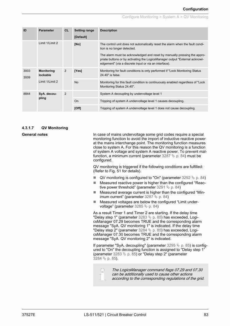
ID Parameter CL Setting range
[Default]
Description
Limit 1/Limit 2 [No] The control unit does not automatically reset the alarm when the fault condi‐tion is no longer detected.
The alarm must be acknowledged and reset by manually pressing the appro‐priate buttons or by activating the LogicsManager output "External acknowl‐edgement" (via a discrete input or via an interface).
3003
3009
Monitoringlockable
Limit 1/Limit 2
2 [Yes] Monitoring for fault conditions is only performed if "Lock Monitoring Status24.40" is false.
No Monitoring for this fault condition is continuously enabled regardless of "LockMonitoring Status 24.40".
8844 SyA. decou‐pling
2 System A decoupling by undervoltage level 1
On Tripping of system A undervoltage level 1 causes decoupling.
[Off] Tripping of system A undervoltage level 1 does not cause decoupling.
4.3.1.7 QV MonitoringIn case of mains undervoltage some grid codes require a specialmonitoring function to avoid the import of inductive reactive powerat the mains interchange point. The monitoring function measuresclose to system A. For this reason the QV monitoring is a functionof system A voltage and system A reactive power. To prevent mal‐function, a minimum current (parameter 3287 Ä p. 84) must beconfigured.QV monitoring is triggered if the following conditions are fulfilled:(Refer to Fig. 51 for details).n QV monitoring is configured to "On" (parameter 3292 Ä p. 84)n Measured reactive power is higher than the configured “Reac‐
tive power threshold” (parameter 3291 Ä p. 84)n Measured average current is higher than the configured “Min‐
imum current” (parameter 3287 Ä p. 84)n Measured voltages are below the configured “Limit under‐
voltage” (parameter 3285 Ä p. 84)As a result Timer 1 and Timer 2 are starting. If the delay time"Delay step 1" (parameter 3283 Ä p. 85) has exceeded, Logi‐csManager 07.29 becomes TRUE and the corresponding alarmmessage "SyA. QV monitoring 1" is indicated. If the delay time"Delay step 2" (parameter 3284 Ä p. 85) has exceeded, Logi‐csManager 07.30 becomes TRUE and the corresponding alarmmessage "SyA. QV monitoring 2" is indicated.If parameter "SyA. decoupling" (parameter 3295 Ä p. 85) is config‐ured to "On" the decoupling function is assigned to “Delay step 1”(parameter 3283 Ä p. 85) or "Delay step 2" (parameter3284 Ä p. 85).
The LogicsManager command flags 07.29 and 07.30can be additionally used to cause other actionsaccording to the corresponding regulations of the grid.
General notes
Configuration
Configure Monitoring > System A > QV Monitoring
37527E LS-511/521 | Circuit Breaker Control 83
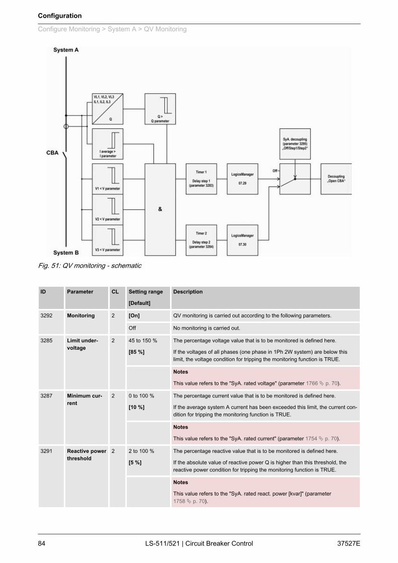
Fig. 51: QV monitoring - schematic
ID Parameter CL Setting range
[Default]
Description
3292 Monitoring 2 [On] QV monitoring is carried out according to the following parameters.
Off No monitoring is carried out.
3285 Limit under‐voltage
2 45 to 150 %
[85 %]
The percentage voltage value that is to be monitored is defined here.
If the voltages of all phases (one phase in 1Ph 2W system) are below thislimit, the voltage condition for tripping the monitoring function is TRUE.
Notes
This value refers to the "SyA. rated voltage" (parameter 1766 Ä p. 70).
3287 Minimum cur‐rent
2 0 to 100 %
[10 %]
The percentage current value that is to be monitored is defined here.
If the average system A current has been exceeded this limit, the current con‐dition for tripping the monitoring function is TRUE.
Notes
This value refers to the "SyA. rated current" (parameter 1754 Ä p. 70).
3291 Reactive powerthreshold
2 2 to 100 %
[5 %]
The percentage reactive value that is to be monitored is defined here.
If the absolute value of reactive power Q is higher than this threshold, thereactive power condition for tripping the monitoring function is TRUE.
Notes
This value refers to the "SyA. rated react. power [kvar]" (parameter1758 Ä p. 70).
Configuration
Configure Monitoring > System A > QV Monitoring
37527ELS-511/521 | Circuit Breaker Control84
ID Parameter CL Setting range
[Default]
Description
3283 Delay step 1 2 0.10 to 99.99 s
[0.50 s]
If the QV monitoring conditions are met, for the delay time configured here, analarm "SyA. QV mon. 1" will be issued and LogicsManager 07.29 becomesTRUE.
Notes
The decoupling function is only activated if "SyA. decoupling" (parameter3295 Ä p. 85) is configured to "Step 1".
3284 Delay step 2 2 0.10 to 99.99 s
[1.50 s]
If the QV monitoring conditions are met, for the delay time configured here, analarm "SyA. QV mon. 2" will be issued and LogicsManager 07.30 becomesTRUE.
Notes
The decoupling function is only activated if "SyA. decoupling" (parameter3295 Ä p. 85) is configured to "Step 2".
3280 Alarm class 2 Class A/B/C/D/E/F/Control
[B]
The alarm class specifies what action should be taken when at least onedelay has been exceeded.
Notes
For additional information refer to Ä Chapter 9.4.1 “Alarm Classes”on page 328
3293 Self acknowl‐edge
2 [Yes] The control unit automatically clears the alarm if the fault condition is nolonger detected.
No The control unit does not automatically reset the alarm when the fault condi‐tion is no longer detected.
The alarm must be acknowledged and reset by manually pressing the appro‐priate buttons or by activating the LogicsManager output "External acknowl‐edgement" (via a discrete input or via an interface).
3294 Monitoringlockable
2 Yes Monitoring for fault conditions is only performed if Lock Monitoring Status24.40 is false.
[No] Monitoring for this fault condition is continuously enabled regardless of LockMonitoring Status 24.40.
3295 SyA. decou‐pling
2 [Off] The QV monitoring function is ignored in the decoupling function.
Step 1 Tripping of QV monitoring step 1 causes decoupling
Step 2 Tripping of QV monitoring step 2 causes decoupling
4.3.1.8 Phase ShiftA vector/phase shift is defined as the sudden variation of thevoltage curve which may be caused by a major generator loadchange.The unit measures the duration of a cycle, where a new measure‐ment is started with each voltage passing through zero. The meas‐ured cycle duration will be compared with an internal quartz-cali‐brated reference time to determine the cycle duration difference ofthe voltage signal.A vector/phase shift as shown in Fig. 52 causes a premature ordelayed zero passage. The determined cycle duration differencecorresponds with the occurring phase shift angle.
General notes
Configuration
Configure Monitoring > System A > Phase Shift
37527E LS-511/521 | Circuit Breaker Control 85
The monitoring may be carried out three-phase or one/three-phase. The monitoring can be configured in different ways. Thevector/phase shift monitor can also be used as an additionalmethod to decouple from the grid. Vector/phase shift monitoring isonly enabled after the monitored voltage exceeds 50% of the PTsecondary rated voltage.
Function "Voltage cycle duration not within thepermissible range"The voltage cycle duration exceeds the configured limitvalue for the phase/vector shift. The result is, that thepower circuit breaker that disconnects from the mains,is opened, the message "SyA. phase shift" is dis‐played, and the logical command variable "07.14" isenabled.
The "Phase shift" configuration parameters are locatedbelow the "SyA. decoupling" function menu on the dis‐play.
ID Parameter CL Setting range
[Default]
Description
3053 Monitoring 2 [1- and 3-phase]
During single-phase voltage phase/vector shift monitoring, tripping occurs ifthe phase/vector shift exceeds the configured threshold value (param‐eter 3054 Ä p. 86) in at least one of the three phases.
3-phase During three-phase voltage phase/vector shift monitoring, tripping occurs onlyif the phase/vector shift exceeds the specified threshold value (param‐eter 3055 Ä p. 86) in all three phases within 2 cycles.
Notes
If a phase/vector shift occurs in one or two phases, the single-phasethreshold value (parameter 3054 Ä p. 86) is taken into consideration; if aphase/vector shift occurs in all three phases, the three-phase threshold value(parameter 3055 Ä p. 86) is taken into consideration.
Single phase monitoring is very sensitive and may lead to nuisance tripping ifthe selected phase angle settings are too small.
3054 Limit 1-phase 2 3 to 30°
[20°]
If the electrical angle of the voltage shifts more than this configured value inany single phase, an alarm with the class configured in parameter3051 Ä p. 86 is initiated. The decoupling procedure will open the CBA.
3055 Limit 3-phase 2 3 to 30°
[8°]
If the electrical angle of the voltage shifts more than this configured value inall three phases, an alarm with the class configured in parameter3051 Ä p. 86 is initiated. The decoupling procedure will open the CBA.
3051 Alarm class 2 A/B/C/D/E/F/Control
[B]
Each limit may be assigned an independent alarm class that specifies whataction should be taken when the limit is surpassed.
Notes
For additional information see Ä Chapter 9.4.1 “Alarm Classes” on page 328.
3052 Self acknowl‐edge
2 [Yes] The control unit automatically clears the alarm if the fault condition is nolonger detected.
Fig. 52: Phase shift
Configuration
Configure Monitoring > System A > Phase Shift
37527ELS-511/521 | Circuit Breaker Control86
ID Parameter CL Setting range
[Default]
Description
No The control unit does not automatically reset the alarm when the fault condi‐tion is no longer detected.
The alarm must be acknowledged and reset by manually pressing the appro‐priate buttons or by activating the LogicsManager output "External acknowl‐edgement" (via a discrete input or via an interface).
3056 Monitoringlockable
2 Yes Monitoring for fault conditions is only performed if "Lock Monitoring Status24.40" is false.
[No] Monitoring for this fault condition is continuously enabled regardless of "LockMonitoring Status 24.40".
4.3.1.9 df/dt (ROCOF)df/dt (rate of change of frequency) monitoring measures the sta‐bility of the frequency. The frequency of a source will vary due tochanging loads and other effects. The rate of these frequencychanges due to the load variances is relatively high compared tothose of a large network.
Function "Rate of change of frequency not withinpermissible limits"The control unit calculates the unit of measure per unitof time. The df/dt is measured over 4 sine waves toensure that it is differentiated from a phase shift. Thisresults in a minimum response time of approximately100 ms (at 50 Hz).
The "df/dt (ROCOF)" configuration parameters arelocated below the "SyA. decoupling" function menu onthe display.
ID Parameter CL Setting range
[Default]
Description
3104 Limit 2 0.1 to 9.9 Hz/s
[2.6 Hz/s]
The df/dt threshold is defined here. If this value is reached or exceeded for atleast the delay time without interruption, an alarm with the class configured inparameter 3101 Ä p. 87 is initiated.
The decoupling procedure will open the CBA.
3105 Delay 2 0.10 to 2.00 s
[0.10 s]
If the monitored rate of df/dt exceeds the threshold value for the delay timeconfigured here, an alarm will be issued.
If the monitored df/dt exceeds the threshold (plus the hysteresis) again be-fore the delay expires the time will be reset.
3101 Alarm class 2 A/B/C/D/E/F/Control
[B]
Each limit may be assigned an independent alarm class that specifies whataction should be taken when the limit is surpassed.
General notes
Configuration
Configure Monitoring > System A > df/dt (ROCOF)
37527E LS-511/521 | Circuit Breaker Control 87
ID Parameter CL Setting range
[Default]
Description
Notes
For additional information see Ä Chapter 9.4.1 “Alarm Classes” on page 328.
3102 Self acknowl‐edge
2 Yes The control unit automatically clears the alarm if the fault condition is nolonger detected.
[No] The control unit does not automatically reset the alarm when the fault condi‐tion is no longer detected.
The alarm must be acknowledged and reset by manually pressing the appro‐priate buttons or by activating the LogicsManager output "External acknowl‐edgement" (via a discrete input or via an interface).
3103 Monitoringlockable
2 Yes Monitoring for fault conditions is only performed if "Lock Monitoring Status24.40" is false.
[No] Monitoring for this fault condition is continuously enabled regardless of "LockMonitoring Status 24.40".
4.3.1.10 System A Phase Rotation
NOTICE!Damage to the control unit and/or generationequipment– Ensure that the control unit is properly connected
to phase voltages on both sides of the circuitbreaker(s) during installation.
Failure to do so may result in damage to the controlunit and/or generation equipment due to the breakerclosing asynchronously or with mismatched phaserotations. Also ensure that phase rotation monitoring isenabled at all connected components (generator,breakers, cable, busbars, etc.).This function will block a connection of systems withwrong phases only under the following conditions:– The voltages being measured are wired correctly
with respect to the phase rotation at the measuringpoints (i.e. the potential transformers in on bothsides of the circuit breaker)
– The voltages being measured are wired so thatangular phase shifts or any interruptions from themeasuring point to the control unit do not exist
– The voltages being measured are wired to the cor‐rect terminals of the control.
– The configured alarm class is of class C or D(breaker relevant alarm).
Correct phase rotation of the phase voltages ensures that damagewill not occur during a breaker closure. The voltage phase rotationalarm checks the phase rotation of the measured voltages and theconfigured phase rotation to ensure they are identical.The directions of rotation are differentiated as "clockwise" and"counter clockwise". With a clockwise field the direction of rotationis "L1-L2-L3"; with a counter clockwise field the direction of rotationis "L1-L3-L2".
General notes
Configuration
Configure Monitoring > System A > System A Phase Rotation
37527ELS-511/521 | Circuit Breaker Control88

If the control is configured for a clockwise rotation and the voltagesinto the unit are calculated as counterclockwise the alarm will beinitiated. The direction of configured rotation being monitored bythe control unit is displayed on the screen.
If this protective function is triggered, the display indi‐cates "SyA. phase rotation" and the logical commandvariable "07.05" will be enabled.
This monitoring function is only enabled if system Avoltage measuring (parameter 1853 Ä p. 72) is config‐ured to "3Ph 4W" or "3Ph 3W" and the measuredvoltage exceeds 50 % of the rated voltage (param‐eter 1768 Ä p. 70) or if system A voltage measuring(parameter 1853 Ä p. 72) is configured to "1Ph 2W"(in this case, the phase rotation is not evaluated, butdefined by the 1Ph2W phase rotation (param‐eter 1859 Ä p. 70)).
ID Parameter CL Setting range
[Default]
Description
3970 Monitoring 2 [On] Phase rotation monitoring is carried out according to the following parame‐ters.
Off No monitoring is carried out.
3974 SyA. phaserotation
2 [CW] The three-phase measured system A voltage is rotating CW (clock-wise; thatmeans the voltage rotates in L1-L2-L3 direction; standard setting).
CCW The three-phase measured system A voltage is rotating CCW (counter clock-wise; that means the voltage rotates in L1-L3-L2 direction).
3971 Alarm class 2 Class A/B/C/D/E/F/Control
[B]
Each limit may be assigned an independent alarm class that specifies whataction should be taken when the limit is surpassed.
Notes
For additional information refer to Ä Chapter 9.4.1 “Alarm Classes”on page 328
3972 Self acknowl‐edge
2 Yes The control unit automatically clears the alarm if the fault condition is nolonger detected.
[No] The control unit does not automatically reset the alarm when the fault condi‐tion is no longer detected.
The alarm must be acknowledged and reset by manually pressing the appro‐priate buttons or by activating the LogicsManager output "External acknowl‐edgement" (via a discrete input or via an interface).
3973 Monitoringlockable
2 Yes Monitoring for fault conditions is only performed if "Lock Monitoring Status24.40" is false.
[No] Monitoring for this fault condition is continuously enabled regardless of "LockMonitoring Status 24.40".
Configuration
Configure Monitoring > System A > System A Phase Rotation
37527E LS-511/521 | Circuit Breaker Control 89
4.3.1.11 System A Voltage AsymmetryVoltage asymmetry is determined by calculating the negativesequence component of a three-phase system. This value isderived from the three delta voltages (phase-phase). Voltageasymmetry monitoring is only active if "SyA. voltage measuring"(parameter 1851 Ä p. 70) is configured to "3Ph 4W" or "3Ph 3W".The threshold is defined as the percentage of that value relative tothe nominal delta voltage. The protective function is triggered if thispercentage value is exceeded.
If this protective function is triggered, the display indi‐cates "SyA. volt. asymmetry" and the logical commandvariable "06.18" will be enabled.
Refer to Ä Chapter 9.1.1 “Triggering Characteristics” on page 241for the triggering characteristic of this monitoring function.
This monitoring function is only enabled if system Avoltage measuring (parameter 1851 Ä p. 70) is config‐ured to "3Ph 4W" or "3Ph 3W".
ID Parameter CL Setting range
[Default]
Description
3921 Monitoring 2 [On] Voltage asymmetry monitoring is carried out according to the followingparameters.
Off No monitoring is carried out.
3924 Limit 2 0.5 to 99.9 %
[10.0 %]
The percentage values that are to be monitored for each threshold limit aredefined here.
If this value is reached or exceeded for at least the delay time without inter‐ruption, the action specified by the alarm class is initiated.
Notes
This value refers to the 'SyA rated voltage' (parameter 1766 Ä p. 70).
3925 Delay 2 0.02 to 99.99 s
[5.00 s]
If the monitored voltage asymmetry exceeds the threshold value for the delaytime configured here, an alarm will be issued.
Notes
If the monitored voltage asymmetry falls below the threshold (minus the hys‐teresis) before the delay expires the time will be reset
3922 Alarm class 2 Class A/B/C/D/E/F/Control
[B]
Each limit may be assigned an independent alarm class that specifies whataction should be taken when the limit is surpassed.
Notes
For additional information refer to Ä Chapter 9.4.1 “Alarm Classes”on page 328
3923 Self acknowl‐edge
2 [Yes] The control unit automatically clears the alarm if the fault condition is nolonger detected.
General notes
Configuration
Configure Monitoring > System A > System A Voltage Asymmetry
37527ELS-511/521 | Circuit Breaker Control90

ID Parameter CL Setting range
[Default]
Description
No The control unit does not automatically reset the alarm when the fault condi‐tion is no longer detected.
The alarm must be acknowledged and reset by manually pressing the appro‐priate buttons or by activating the LogicsManager output "External acknowl‐edgement" (via a discrete input or via an interface).
3926 Monitoringlockable
2 Yes Monitoring for fault conditions is only performed if "Lock Monitoring Status24.40" is false.
[No] Monitoring for this fault condition is continuously enabled regardless of "LockMonitoring Status 24.40".
4.3.1.12 System A Voltage IncreaseVoltage is monitored depending on parameter "Monitoring" (param‐eter 8806 Ä p. 92). This function allows the monitoring of thevoltage quality over a longer time period. It is realized as a 10minute moving average1. The function is only active, if system A iswithin the operation window. If "SyA. voltage measuring" (param‐eter 1853 Ä p. 72) is configured to a three-phase measurement,the slow voltage increase alarm is monitoring the individual three-phase voltages of the system A according to parameter "AND char‐acteristics" (parameter 8849 Ä p. 92). The parameter "SyA. decou‐pling volt. incr." (parameter 8808 Ä p. 92) determines if a voltageincrease shall trigger a system A decoupling or not.
If this protective function is triggered, the display indi‐cates "SyA. volt. increase". The alarm can be incorpo‐rated into the system A decoupling function.
The average is set to "SyA. rated voltage" (parameter1766 Ä p. 70) if:– Frequency is not in the operation window OR– Monitoring (parameter 8806 Ä p. 92) is "Off" OR– "Monitoring lockable" is active (parameter
8833 Ä p. 92) OR– Monitoring is tripped AND the measured voltage is
again in the operation windowBack synchronization is only possible, if:– The 10 minute average value is smaller than the
defined limit AND– The actual measured value is inside the operation
window AND– The system A settling time is over
Please be aware that if "SyA. voltage monitoring"(parameter 1771 Ä p. 74) is configured to "All" and thesystem A voltage increase monitoring (parameter8806 Ä p. 92) is used, that this function only monitors"Phase - neutral".
General notes
Configuration
Configure Monitoring > System A > System A Voltage Increase
37527E LS-511/521 | Circuit Breaker Control 91

1 Please be aware that this monitoring function waschanged with software version 1.01xx or higher. For anolder version of this manual please contact our salessupport.
ID Parameter CL Setting range
[Default]
Description
8806 Monitoring 2 On Voltage increase monitoring is carried out according to the following parame‐ters.
[Off] No monitoring is carried out.
8807 Limit 2 100 to 150 %
[110 %]
The percentage voltage value that is to be monitored is defined here.
If the average voltage over 10 minutes is higher, the action specified by thealarm class is initiated.
Notes
This value refers to the "SyA. rated voltage" (parameter 1766 Ä p. 70).
8808 SyA. decou‐pling voltageincrease
2 Yes Voltage increase monitoring does cause decoupling.
[No] Voltage increase monitoring does not cause decoupling.
8831 Alarm class 2 Class A/B/C/D/E/F/Control
[B]
Each limit may be assigned an independent alarm class that specifies whataction should be taken when the limit is surpassed.
Notes
For additional information refer to Ä Chapter 9.4.1 “Alarm Classes”on page 328
8832 Self acknowl‐edge
2 [Yes] The control unit automatically clears the alarm if the fault condition is nolonger detected.
No The control unit does not automatically reset the alarm when the fault condi‐tion is no longer detected.
The alarm must be acknowledged and reset by manually pressing the appro‐priate buttons or by activating the LogicsManager output "External acknowl‐edgement" (via a discrete input or via an interface).
8833 Monitoringlockable
2 Yes Monitoring for fault conditions is only performed if "Lock Monitoring Status24.40" is false
[No] Monitoring for this fault condition is continuously enabled regardless of "LockMonitoring Status 24.40".
8849 AND character‐istics
2 On If the 10 minute voltage averages of all phases exceed the limit, the moni‐toring is tripping.
[Off] If the 10 minute voltage average of at least one phase exceeds the limit, themonitoring is tripping.
4.3.1.13 System A Time-Dependent VoltageVoltage is monitored depending on parameter "SyA. voltage meas‐uring" (parameter 1851 Ä p. 70). This monitoring function is sup‐porting a dynamic stabilization of mains. For this reason a FRT(Fault-Ride-Through) curve can be defined.
General notes
Configuration
Configure Monitoring > System A > System A Time-Dependent Vo...
37527ELS-511/521 | Circuit Breaker Control92
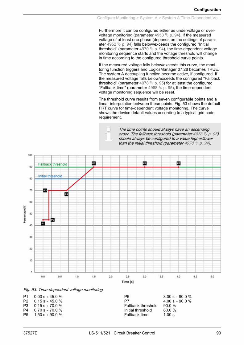
Furthermore it can be configured either as undervoltage or over‐voltage monitoring (parameter 4953 Ä p. 94). If the measuredvoltage of at least one phase (depends on the settings of param‐eter 4952 Ä p. 94) falls below/exceeds the configured "Initialthreshold" (parameter 4970 Ä p. 94), the time-dependent voltagemonitoring sequence starts and the voltage threshold will changein time according to the configured threshold curve points.If the measured voltage falls below/exceeds this curve, the moni‐toring function triggers and LogicsManager 07.28 becomes TRUE.The system A decoupling function became active, if configured. Ifthe measured voltage falls below/exceeds the configured "Fallbackthreshold" (parameter 4978 Ä p. 95) for at least the configured"Fallback time" (parameter 4968 Ä p. 95), the time-dependentvoltage monitoring sequence will be reset.The threshold curve results from seven configurable points and alinear interpolation between these points. Fig. 53 shows the defaultFRT curve for time-dependent voltage monitoring. The curveshows the device default values according to a typical grid coderequirement.
The time points should always have an ascendingorder. The fallback threshold (parameter 4978 Ä p. 95)should always be configured to a value higher/lowerthan the initial threshold (parameter 4970 Ä p. 94).
Fig. 53: Time-dependent voltage monitoringP1 0.00 s → 45.0 %P2 0.15 s → 45.0 %P3 0.15 s → 70.0 %P4 0.70 s → 70.0 %P5 1.50 s → 90.0 %
P6 3.00 s → 90.0 %P7 4.00 s → 90.0 %Fallback threshold 90.0 %Initial threshold 80.0 %Fallback time 1.00 s
Configuration
Configure Monitoring > System A > System A Time-Dependent Vo...
37527E LS-511/521 | Circuit Breaker Control 93
ID Parameter CL Setting range
[Default]
Description
4950 Monitoring 2 On Time-dependent voltage monitoring is carried out according to the followingparameters.
[Off] No monitoring is carried out.
4952 AND character‐istics
2 On Each phase falls below/exceeds the threshold for tripping.
[Off] At least one phase falls below/exceeds the threshold for tripping.
4953 Monitoring at 2 Selects whether the system shall do over- or undervoltage monitoring.
[Underrun] The undervoltage monitoring is carried out (The monitoring function triggers ifthe measured voltage is below the curve).
Overrun The overvoltage monitoring is carried out (The monitoring function triggers ifthe measured voltage exceeds the curve).
4970 Init threshold 2 0.0 to 150.0 %
[80.0 %]
The time-dependent voltage monitoring initial threshold is configured here. Ifthe measured voltage falls below/exceeds this threshold, the monitoringsequence starts and the voltage threshold will change in time according to theconfigured threshold curve points.
If the measured voltage falls below/exceeds this curve, the monitoring func‐tion triggers and the configured relay will energize.
4978 Fallbackthreshold
2 0.0 to 150.0 %
[90.0 %]
The time-dependent voltage monitoring fallback voltage is configured here. Ifthe measured voltage falls below/exceeds the voltage configured here for atleast the configured "Fallback time" (parameter 4968 Ä p. 95), the monitoringsequence will be reset.
Notes
This parameter should always be configured to a value higher/lower than the"Init threshold" (parameter 4970 Ä p. 94) for proper operation.
The parameter "Point 7 voltage" (parameter 4977 Ä p. 95) is used as fallbackthreshold if it is configured to a value higher/lower than the parameter "Fall‐back threshold" (parameter 4978 Ä p. 94).
4968 Fallback time 2 0.00 to 320.00 s
[1.00 s]
The time-dependent voltage monitoring fallback time is configured here. If themeasured voltage falls below/exceeds the configured "Fallback threshold"(parameter 4978 Ä p. 94) for at least the time configured here, the monitoringsequence will be reset.
4961
4962
4963
4964
4965
4966
4967
Point {x} time
[x = 1 to 7]
2 0.00 to 320.00 s
4961: [0.00 s]
4962: [0.15 s]
4963: [0.15 s]
4964: [0.70 s]
4965: [1.50 s]
4966: [3.00 s]
4967: [4.00 s]
The time values of time-dependent voltage monitoring time points are config‐ured here.
Configuration
Configure Monitoring > System A > System A Time-Dependent Vo...
37527ELS-511/521 | Circuit Breaker Control94
ID Parameter CL Setting range
[Default]
Description
4971
4972
4973
4974
4975
4976
4977
Point {x}voltage
[x = 1 to 7]
2 0.0 to 150.0 %
4971: [45.0 %]
4972: [45.0 %]
4973: [70.0 %]
4974: [70.0 %]
4975: [90.0 %]
4976: [90.0 %]
4977: [90.0 %]
The voltage values of time-dependent voltage monitoring voltage points areconfigured here.
Notes
Please avoid a setting between 0.1 % and 5.0 %.
4951 Alarm class 2 Class A/B/C/D/E/F/Control
[B]
Each limit may be assigned an independent alarm class that specifies whataction should be taken when the limit is surpassed.
Notes
For additional information refer to Ä Chapter 9.4.1 “Alarm Classes”on page 328
4959 Self acknowl‐edge
2 [Yes] The control unit automatically clears the alarm if the fault condition is nolonger detected.
No The control unit does not automatically reset the alarm when the fault condi‐tion is no longer detected.
The alarm must be acknowledged and reset by manually pressing the appro‐priate buttons or by activating the LogicsManager output "External acknowl‐edgement" (via a discrete input or via an interface).
4999 Monitoringlockable
2 Yes Monitoring for fault conditions is only performed if "Lock Monitoring Status24.40" is false.
[No] Monitoring for this fault condition is continuously enabled regardless of "LockMonitoring Status 24.40".
4989 SyA. decou-pling
2 On Time-dependent voltage monitoring does cause decoupling.
[Off] Time-dependent voltage monitoring does not cause decoupling.
4.3.2 System BID Parameter CL Setting range
[Default]
Description
1770 SyB. voltagemonitoring
2 The unit can either monitor the phase-neutral (wye) voltages or the phase‐phase (delta) voltages.
If the controller is used in a compensated or isolated network, voltage protec‐tion monitoring should be configured as phase-neutral to prevent earth-faultsresulting in tripping of the voltage protections.
[Phase -phase]
The phase-phase voltage will be monitored and all subsequent parametersconcerning voltage monitoring "system B" are referred to this value (VL-L).
Configuration
Configure Monitoring > System B
37527E LS-511/521 | Circuit Breaker Control 95
ID Parameter CL Setting range
[Default]
Description
Phase - neutral The phase-neutral voltage will be monitored and all subsequent parametersconcerning voltage monitoring "system B" are referred to this value (VL-N).
Notes
WARNING: This parameter influences the protective functions.
4.3.2.1 System B Operating Voltage / Frequency
The operating voltage/frequency parameters are usedto check if the values are in range when performing adead bus closure and synchronization.It is recommended to configure the operating limitswithin the monitoring limits.
ID Parameter CL Setting range
[Default]
Description
5800 Upper voltagelimit
2 100 to 150 %
[110 %]
The maximum permissible positive deviation of the system B voltage from thesystem B rated voltage (parameter 1768 Ä p. 70) is configured here.
This value may be used as a voltage limit switch. The conditional state of thisswitch may be used as a command variable for the LogicsManager (02.03).
5801 Lower voltagelimit
2 50 to 100 %
[90 %]
The maximum permissible negative deviation of the system B voltage fromthe system B rated voltage (parameter 1768 Ä p. 70) is configured here.
This value may be used as a voltage limit switch. The conditional state of thisswitch may be used as a command variable for the LogicsManager (02.03).
5802 Upper fre‐quency limit
2 100.0 to 150.0%
[105.0 %]
The maximum permissible positive deviation of the system B frequency fromthe rated system frequency (parameter 1750 Ä p. 70) is configured here.
This value may be used as a frequency limit switch. The conditional state ofthis switch may be used as a command variable for the LogicsManager(02.04).
5803 Lower fre‐quency limit
2 50.0 to 100.0 %
[95.0 %]
The maximum permissible negative deviation of the system B frequency fromthe rated system frequency (parameter 1750 Ä p. 70) is configured here.
This value may be used as a frequency limit switch. The conditional state ofthis switch may be used as a command variable for the LogicsManager(02.04).
General notes
Configuration
Configure Monitoring > System B > System B Operating Voltage...
37527ELS-511/521 | Circuit Breaker Control96
4.3.2.2 System B Voltage Phase Rotation
NOTICE!Damage to the control unit and/or generationequipment– Ensure that the control unit is properly connected
to phase voltages on both sides of the circuitbreaker(s) during installation.
Failure to do so may result in damage to the controlunit and/or generation equipment due to the breakerclosing asynchronously or with mismatched phaserotations. Also ensure that phase rotation monitoring isenabled at all connected components (generator,breakers, cable, busbars, etc.).This function will block a connection of systems withwrong phases only under the following conditions:– The voltages being measured are wired correctly
with respect to the phase rotation at the measuringpoints (i.e. the potential transformers in on bothsides of the circuit breaker)
– The voltages being measured are wired so thatangular phase shifts or any interruptions from themeasuring point to the control unit do not exist
– The voltages being measured are wired to the cor‐rect terminals of the control.
– The configured alarm class is of class C or D(breaker relevant alarm).
Correct phase rotation of the phase voltages ensures that damagewill not occur during a breaker closure to either the mains or thegenerator. The voltage phase rotation alarm checks the phaserotation of the voltages and the configured phase rotation to ensurethey are identical.The directions of rotation are differentiated as "clockwise" and"counter clockwise". With a clockwise field the direction of rotationis "L1-L2-L3"; with a counter clockwise field the direction of rotationis "L1-L3-L2".If the control is configured for a clockwise rotation and the voltagesinto the unit are calculated as counterclockwise the alarm will beinitiated. The direction of configured rotation being monitored bythe control unit is displayed on the screen.
If this protective function is triggered, the display indi‐cates "SyB. phase rotation" and the logical commandvariable "06.21" will be enabled.
This monitoring function is only enabled if "SyB.voltage measuring" (parameter 1851 Ä p. 70) is con‐figured to "3Ph 4W" or "3Ph 3W" and the measuredvoltage exceeds 50 % of the rated voltage (param‐eter 1766 Ä p. 70) or if "SyB. voltage measuring"(parameter 1851 Ä p. 70) is configured to "1Ph 2W"(in this case, the phase rotation is not evaluated, butdefined by the 1Ph2W phase rotation (param‐eter 1859 Ä p. 70)).
General notes
Configuration
Configure Monitoring > System B > System B Voltage Phase Ro...
37527E LS-511/521 | Circuit Breaker Control 97

ID Parameter CL Setting range
[Default]
Description
3950 Monitoring 2 On Phase rotation monitoring is carried out according to the following parame‐ters.
[Off] No monitoring is carried out.
3954 SyB. phaserotation
2 [CW] The three-phase measured system B voltage is rotating CW (clock-wise; thatmeans the voltage rotates in L1-L2-L3 direction; standard setting).
CCW The three-phase measured system B voltage is rotating CCW (counter clock-wise; that means the voltage rotates in L1-L3-L2 direction).
3951 Alarm class 2 Class A/B/C/D/E/F/Control
[F]
Each limit may be assigned an independent alarm class that specifies whataction should be taken when the limit is surpassed.
Notes
For additional information refer to Ä Chapter 9.4.1 “Alarm Classes”on page 328
3952 Self acknowl‐edge
2 Yes The control unit automatically clears the alarm if the fault condition is nolonger detected.
[No] The control unit does not automatically reset the alarm when the fault condi‐tion is no longer detected.
The alarm must be acknowledged and reset by manually pressing the appro‐priate buttons or by activating the LogicsManager output "External acknowl‐edgement" (via a discrete input or via an interface).
3953 Monitoringlockable
2 Yes Monitoring for fault conditions is only performed if "Lock Monitoring Status24.40" is false.
[No] Monitoring for this fault condition is continuously enabled regardless of "LockMonitoring Status 24.40".
4.3.3 Breaker4.3.3.1 Configure CBA
Circuit breaker monitoring contains two alarms: A "breaker reclose"alarm and a "breaker open" alarm."Breaker reclose alarm"If the control initiates a close of the breaker and the breaker fails toclose after the configured number of attempts the monitoring CBAalarm will be initiated (refer to parameter "CBA maximum attemptsof closure", parameter 3419 Ä p. 100).
If this protective function is triggered, the display indi‐cates "CBA fail to close" and the logical command vari‐able "08.07" will be enabled.
"Breaker open alarm"If the control is attempting to open the circuit breaker and it fails tosee that the CBA is open within the configured time in secondsafter issuing the breaker open command then the monitoring CBAalarm will be initiated (refer to parameter "CBA open monitoring",parameter 3421 Ä p. 100).
General notes
Configuration
Configure Monitoring > Breaker > Configure CBA
37527ELS-511/521 | Circuit Breaker Control98

If this protective function is triggered, the display indi‐cates "CBA fail to open" and the logical command vari‐able "08.08" will be enabled.
ID Parameter CL Setting range
[Default]
Description
2620 CBA moni‐toring
2 [On] Monitoring of the CBA is carried out according to the following parameters.
Off Monitoring is disabled.
2621 CBA alarmclass
2 Class A/B
[B]
Each limit may be assigned an independent alarm class that specifies whataction should be taken when the limit is surpassed.
Notes
For additional information refer to Ä Chapter 9.4.1 “Alarm Classes”on page 328
3419 CBA maximumclosingattempts
2 1 to 10
[5]
The maximum number of breaker closing attempts is configured in thisparameter (relay output "Command: close CBA").
When the breaker reaches the configured number of attempts, a "CBA fail toclose" alarm is issued.
The counter for the closure attempts will be reset as soon as the "Reply CBA"is de-energized for at least 5 seconds to signal a closed CBA.
3421 CBA openmonitoring
2 0.10 to 5.00 s
[2.00 s]
If the "Reply CBA" is not detected as energized once this timer expires, a"CBA fail to open" alarm is issued. This timer initiates as soon as the "openbreaker" sequence begins. The alarm configured in parameter 2621 Ä p. 99is issued.
2622 CBA moni‐toring lockable
2 Yes Monitoring for fault conditions is only performed if "Lock Monitoring Status24.40 is false".
[No] Monitoring for this fault condition is continuously enabled regardless of "LockMonitoring Status 24.40".
4.3.3.2 Synchronization CBA
For synchronization with two systems please see addi‐tionally Ä Chapter 9.5.1 “Synchronization Of System Aand System B” on page 334.
ID Parameter CL Setting range
[Default]
Description
3070 Monitoring 2 [On] Monitoring of the CBA synchronization is carried out according to the fol‐lowing parameters.
Off Monitoring is disabled.
Configuration
Configure Monitoring > Breaker > Synchronization CBA
37527E LS-511/521 | Circuit Breaker Control 99
ID Parameter CL Setting range
[Default]
Description
3073 Delay 2 3 to 999 s
[60 s]
If it was not possible to synchronize the CBA within the time configured here,an alarm will be issued.
The message "CBA syn. timeout" is issued and the logical command variable"08.31" will be enabled.
3071 Alarm class 2 Class A/B/C/D/E/F/Control
[B]
Each limit may be assigned an independent alarm class that specifies whataction should be taken when the limit is surpassed.
Notes
For additional information refer to Ä Chapter 9.4.1 “Alarm Classes”on page 328
3072 Self acknowl‐edge
2 Yes The control unit automatically clears the alarm if the fault condition is nolonger detected.
[No] The control unit does not automatically reset the alarm when the fault condi‐tion is no longer detected.
The alarm must be acknowledged and reset by manually pressing the appro‐priate buttons or by activating the LogicsManager output "External acknowl‐edgement" (via a discrete input or via an interface).
3075 Monitoringlockable
2 Yes Monitoring for fault conditions is only performed if "Lock Monitoring Status24.40" is false.
[No] Monitoring for this fault condition is continuously enabled regardless of "LockMonitoring Status 24.40".
4.3.3.3 CBA Unload Mismatch
ID Parameter CL Setting range
[Default]
Description
8819 Unload triplevel CBA
2 0.5 to 99.9 %
[3.0 %]
If the monitored power of system A falls below this value, a "CBA open" com‐mand will be issued.
Notes
This value refers to the "SyA. rated active power" (parameter 1752 Ä p. 70).
8835 Delay 2 1 to 999 s
[60 s]
If the monitored system A power does not fall below the limit configured inparameter 8819 Ä p. 100 before the time configured here expires, a "CBAopen" command will be issued together with an alarm "CBA unload mis‐match" and the logical command variable "08.36" will be enabled.
8836 Alarm class 2 Class A/B/C/D/E/F/Control
[B]
Each limit may be assigned an independent alarm class that specifies whataction should be taken when the limit is surpassed.
Notes
For additional information refer to Ä Chapter 9.4.1 “Alarm Classes”on page 328
8837 Self acknowl‐edge
2 Yes The control unit automatically clears the alarm if the fault condition is nolonger detected.
Configuration
Configure Monitoring > Breaker > CBA Unload Mismatch
37527ELS-511/521 | Circuit Breaker Control100

ID Parameter CL Setting range
[Default]
Description
[No] The control unit does not automatically reset the alarm when the fault condi‐tion is no longer detected.
The alarm must be acknowledged and reset by manually pressing the appro‐priate buttons or by activating the LogicsManager output "External acknowl‐edgement" (via a discrete input or via an interface).
8846 Monitoringlockable
2 Yes Monitoring for fault conditions is only performed if "Lock Monitoring Status24.40 is false."
[No] Monitoring for this fault condition is continuously enabled regardless of "LockMonitoring Status 24.40".
4.3.3.4 System A / System B Phase RotationCorrect phase rotation of the phase voltages ensures that damagewill not occur during a breaker closure. The voltage phase rotationalarm checks, if the phase rotation of the measured voltage sys‐tems are identical.If the control unit detects different phase rotations of system A andsystem B, the alarm will be initiated and a breaker synchronizationis inhibited. However, this alarm will not prevent a dead busbar clo‐sure, i.e. a dead bus start.
If this protective function is triggered, the display indi‐cates "Ph.rotation mismatch" and the logical commandvariable "08.33" will be enabled.
This monitoring function is only enabled if system Avoltage measuring (parameter 1851 Ä p. 70) andsystem B voltage measuring (parameter 1853 Ä p. 72)are configured to "3Ph 4W" or "3Ph 3W" and themeasured voltage exceeds 50 % of the rated voltage(parameter 1766 Ä p. 70) or if system A voltage meas‐uring (parameter 1851 Ä p. 70) and system B voltagemeasuring (parameter 1853 Ä p. 72) are configured to"1Ph 2W". In this case, the phase rotation is not evalu‐ated, but defined by the 1Ph2W phase rotation(parameter 1859 Ä p. 70).
ID Parameter CL Setting range
[Default]
Description
2940 Monitoring 2 [On] Phase rotation monitoring is carried out according to the following parameters
Off Monitoring is disabled.
2941 Alarm class 2 Class A/B/C/D/E/F/Control
[B]
Each limit may be assigned an independent alarm class that specifies whataction should be taken when the limit is surpassed.
General notes
Configuration
Configure Monitoring > Breaker > System A / System B Phase ...
37527E LS-511/521 | Circuit Breaker Control 101
ID Parameter CL Setting range
[Default]
Description
Notes
For additional information refer to Ä Chapter 9.4.1 “Alarm Classes”on page 328
2942 Self acknowl‐edge
2 [Yes] The control unit automatically clears the alarm if the fault condition is nolonger detected.
No The control unit does not automatically reset the alarm when the fault condi‐tion is no longer detected.
The alarm must be acknowledged and reset by manually pressing the appro‐priate buttons or by activating the LogicsManager output "External acknowl‐edgement" (via a discrete input or via an interface).
2945 Monitoringlockable
2 Yes Monitoring for fault conditions is only performed if "Lock Monitoring Status24.40 is false".
[No] Monitoring for this fault condition is continuously enabled regardless of "LockMonitoring Status 24.40".
4.3.4 Miscellaneous4.3.4.1 Alarm Acknowledgement
ID Parameter CL Setting range
[Default]
Description
1756 Time until hornreset
0 0 to 1,000 s After each alarm of alarm class B through F occurs, the alarm LED flashesand the horn (command variable 01.12) is enabled. After the delay time "timeuntil horn reset" has expired, the flashing LED changes into a steady light andthe horn (command variable 01.12) is disabled. The alarm LED flashes untilthe alarm has been acknowledged either via the push button, the LogicsMan‐ager, or the interface.
Notes
If this parameter is configured to 0, the horn will remain active until it will beacknowledged.
12490 Ext. acknowl‐edge
(Externalacknowledg‐ment of alarms)
2 Determined byLogicsManager
[(DI 02 & 1) &1]
It is possible to acknowledge all alarms simultaneously from remote, e.g. witha discrete input. The logical output of the LogicsManager has to becomeTRUE twice.
The first time is for acknowledging the horn, the second for all alarm mes‐sages. The On-delay time is the minimum time the input signals have to be"1". The Off-delay time is the time how long the input conditions have to be"0" before the next high signal is accepted.
Once the conditions of the LogicsManager have been fulfilled the alarms willbe acknowledged.
The first high signal into the discrete input acknowledges the command vari‐able 01.12 (horn).
The second high signal acknowledges all inactive alarm messages.
Configuration
Configure Monitoring > Miscellaneous > Alarm Acknowledgement
37527ELS-511/521 | Circuit Breaker Control102

ID Parameter CL Setting range
[Default]
Description
Notes
For information on the LogicsManager and its default settings seeÄ Chapter 9.3.1 “LogicsManager Overview” on page 299.
12959 Lock Moni-toring
2 Determined byLogicsManager
[(DI 01 & 1) &1]
As long as the conditions of the LogicsManager have been fulfilled, all moni‐toring functions which are configured “Monitoring lockable” to “Yes” arelocked.
4.3.4.2 CAN InterfaceThe CANopen interface is monitored. If the interface does notreceive a Receive Process Data Object (RPDO) before the delayexpires, an alarm will be initiated.
If this protective function is triggered, the display indi‐cates "CANopen interface 1" and the logical commandvariable "08.18" will be enabled.
ID Parameter CL Setting range
[Default]
Description
3150 Monitoring 2 On CANopen interface monitoring is carried out according to the following param‐eters.
[Off] Monitoring is disabled.
3154 Delay 2 0.01 to 650.00 s
[0.20 s]
The maximum receiving break is configured with this parameter.
If the interface does not receive an RPDO within this time, the action specifiedby the alarm class is initiated. The delay timer is re-initialized after every mes‐sage is received.
3151 Alarm class 2 Class A/B/C/D/E/F/Control
[B]
Each limit may be assigned an independent alarm class that specifies whataction should be taken when the limit is surpassed.
Notes
For additional information refer to Ä Chapter 9.4.1 “Alarm Classes”on page 328
3152 Self acknowl‐edge
2 [Yes] The control unit automatically clears the alarm if the fault condition is nolonger detected.
No The control unit does not automatically reset the alarm when the fault condi‐tion is no longer detected.
The alarm must be acknowledged and reset by manually pressing the appro‐priate buttons or by activating the LogicsManager output "External acknowl‐edgement" (via a discrete input or via an interface).
3153 Monitoringlockable
2 Yes Monitoring for fault conditions is only performed if "Lock Monitoring Status24.40 is false".
[No] Monitoring for this fault condition is continuously enabled regardless of "LockMonitoring Status 24.40".
General notes
Configuration
Configure Monitoring > Miscellaneous > CAN Interface
37527E LS-511/521 | Circuit Breaker Control 103
4.3.4.3 Battery Overvoltage (Level 1 & 2)There are two battery overvoltage alarm levels available in the con‐trol. Both alarms are definite time alarms and. Monitoring of thevoltage is done in two steps.
If this protective function is triggered, the display indi‐cates "Bat. overvoltage 1" or "Bat. overvoltage 2" andthe logical command variable "08.01" or "08.02" will beenabled.
Refer to Ä Chapter 9.1.1 “Triggering Characteristics” on page 241for the triggering characteristic of this monitoring function.
ID Parameter CL Setting range
[Default]
Description
3450
3456
Monitoring 2 [On] Overvoltage monitoring of the battery voltage is carried out according to thefollowing parameters. Both values may be configured independent from eachother (prerequisite: Level 1 > Level 2).
Off Monitoring is disabled for Level 1 limit and/or Level 2 limit.
3454
3460
Limit 2 8.0 to 42.0 V
3454: [32.0 V]
3460: [35.0 V]
The threshold values that are to be monitored are defined here.
If the monitored battery voltage reaches or exceeds this value for at least thedelay time without interruption, the action specified by the alarm class is initi‐ated.
3455
3461
Delay 2 0.02 to 99.99 s
3455: [5.00 s]
3461: [1.00 s]
If the monitored battery voltage exceeds the threshold value for the delay timeconfigured here, an alarm will be issued.
Notes
If the monitored battery voltage falls below the threshold (minus the hyste‐resis) before the delay expires the time will be reset.
3451
3457
Alarm class 2 Class A/B/C/D/E/F/Control
[B]
Each limit may be assigned an independent alarm class that specifies whataction should be taken when the limit is surpassed.
Notes
For additional information refer to Ä Chapter 9.4.1 “Alarm Classes”on page 328
3452
3458
Self acknowl‐edge
2 [Yes] The control unit automatically clears the alarm if the fault condition is nolonger detected.
No The control unit does not automatically reset the alarm when the fault condi‐tion is no longer detected.
The alarm must be acknowledged and reset by manually pressing the appro‐priate buttons or by activating the LogicsManager output "External acknowl‐edgement" (via a discrete input or via an interface).
3453
3459
Monitoringlockable
(Limit 1 / Limit2)
2 [Yes] Monitoring for fault conditions is only performed if "Lock Monitoring Status24.40 is false".
No Monitoring for this fault condition is continuously enabled regardless of "LockMonitoring Status 24.40".
General notes
Configuration
Configure Monitoring > Miscellaneous > Battery Overvoltage (Level...
37527ELS-511/521 | Circuit Breaker Control104
4.3.4.4 Battery Undervoltage (Level 1 & 2)There are two battery undervoltage alarm levels available in thecontrol. Both alarms are definite time alarms. Monitoring of thevoltage is done in two steps.
If this protective function is triggered, the display indi‐cates "Bat. undervoltage 1" or "Bat. undervoltage 2"and the logical command variable "08.03" or "08.04"will be enabled.
Refer to Ä Chapter 9.1.1 “Triggering Characteristics” on page 241for the triggering characteristic of this monitoring function.
ID Parameter CL Setting range
[Default]
Description
3500
3506
Monitoring 2 [On] Undervoltage monitoring of the battery voltage is carried out according to thefollowing parameters. Both values may be configured independent from eachother (prerequisite: Level 1 > Level 2).
Off Monitoring is disabled for Level 1 limit and/or Level 2 limit.
3504
3510
Limit 2 8.0 to 42.0 V
3404: [24.0 V]
3510: [20.0 V]
The threshold values that are to be monitored are defined here.
If the monitored battery voltage reaches or falls below this value for at leastthe delay time without interruption, the action specified by the alarm class isinitiated.
Notes
The default monitoring limit for battery undervoltage is 24 Vdc after 60 sec‐onds.
This is because in normal operation the terminal voltage is approximately26 Vdc (alternator charged battery).
3505
3511
Delay 2 0.02 to 99.99 s
3405: [60.00 s]
3511: [10.00 s]
If the battery voltage falls below the threshold value for the delay time config‐ured here, an alarm will be issued.
Notes
If the battery voltage exceeds the threshold (plus the hysteresis) again beforethe delay expires the time will be reset.
3501
3507
Alarm class 2 Class A/B/C/D/E/F/Control
[B]
Each limit may be assigned an independent alarm class that specifies whataction should be taken when the limit is surpassed.
Notes
For additional information refer to Ä Chapter 9.4.1 “Alarm Classes”on page 328
3502
3508
Self acknowl‐edge
2 Yes The control unit automatically clears the alarm if the fault condition is nolonger detected.
[No] The control unit does not automatically reset the alarm when the fault condi‐tion is no longer detected.
The alarm must be acknowledged and reset by manually pressing the appro‐priate buttons or by activating the LogicsManager output "External acknowl‐edgement" (via a discrete input or via an interface).
General notes
Configuration
Configure Monitoring > Miscellaneous > Battery Undervoltage (Leve...
37527E LS-511/521 | Circuit Breaker Control 105
ID Parameter CL Setting range
[Default]
Description
3503
3509
Monitoringlockable
2 Yes Monitoring for fault conditions is only performed if "Lock Monitoring Status24.40 is false".
[No] Monitoring for this fault condition is continuously enabled regardless of "LockMonitoring Status 24.40".
4.3.4.5 Multi-Unit Missing MembersThe multi-unit missing members monitoring function checkswhether all participating units are available (sending data on theCAN bus).If the number of available units is less than the number of mem‐bers configured in parameter 4063 Ä p. 107 for at least the delaytime, the display indicates "Missing members" and the logical com‐mand variable "08.17" will be enabled.
After energizing the unit, a delay is started, whichallows a possible "Missing members" alarm to becomeactive. This delay depends on the Node-ID of the unit(parameter 8950 Ä p. 124) and the transfer rate of aload share / LS-5 fast message (param‐eter 9921 Ä p. 123) and may last for approximately140 seconds for a high Node-ID (e.g. 127). This delayserves for detecting the Master of a CAN bus connec‐tion. Approximately two minutes after energizing theunit, the alarm delay will be set to a fix time, whichdepends on the setting of param‐eter 9921 Ä p. 123 (Transfer rate LS fast message)and is in the range between 3 to 9 seconds.
ID Parameter CL Setting range
[Default]
Description
4060 Monitoring 2 On Multi-unit missing members monitoring is carried out.
[Off] Monitoring is disabled.
Notes
This parameter only applies to application mode .
4063 Number of LS5communi‐cating
2 2 to 64 The number participating of LS-5 units is configured here.
4061 Alarm class 2 Class A/B/C/D/E/F/Control
[B]
This function may be assigned an independent alarm class that specifieswhat action should be taken when this function triggers an alarm.
Notes
For additional information refer to Ä Chapter 9.4.1 “Alarm Classes”on page 328.
General notes
Configuration
Configure Monitoring > Miscellaneous > Multi-Unit Missing Members
37527ELS-511/521 | Circuit Breaker Control106
ID Parameter CL Setting range
[Default]
Description
4062 Self acknowl‐edge
2 Yes The control automatically clears the alarm if the fault condition is no longerdetected.
[No] The control does not automatically reset the alarm when the fault condition isno longer detected. The alarm must be acknowledged and reset by manuallypressing the appropriate buttons or by activating the LogicsManager output"External acknowledgement" (via a discrete input or via an interface).
4.4 Configure Application4.4.1 Application Mode
The unit can be configured to four different application modes. Foradditional information refer to Ä Chapter 6 “Application”on page 163.
In the application modes and some parametersare fixed to the corresponding parameters in theeasYgen.
In the application modes and some parametersare preconfigured to fixed values. In these modesthese parameters cannot be accessed via front panelor ToolKit.– Check the following parameters if you change the
application mode from or to or .
Device number (parameter1702 Ä p. 67)
Variable system (parameter8816 Ä p. 117)
Node-ID CAN bus 1 (parameter8950 Ä p. 124)
Synchronization mode (parameter5728 Ä p. 115)
Startup in mode (parameter8827 Ä p. 121)
Mains power measurement (parameter8813 Ä p. 116)
Isolation switch (parameter8815 Ä p. 116)
Dead bus closure (parameter8801 Ä p. 114)
Segment number System A (parameter8810 Ä p. 116)
Connect A dead to B dead (parameter8802 Ä p. 114)
Segment number System B (parameter8811 Ä p. 116)
Connect A dead to B alive (parameter8803 Ä p. 114)
Mains connection (parameter8814 Ä p. 116)
Connect A alive to B dead (parameter8804 Ä p. 114)
Open CBA in manual (parameter8828 Ä p. 109)
Connect synchronous mains (param‐eter 8820 Ä p. 110)
Max. phase angle (parameter8821 Ä p. 110)
Delay time phi max. (parameter8822 Ä p. 110)
General notes
Fixed parameters
Configuration
Configure Application > Application Mode
37527E LS-511/521 | Circuit Breaker Control 107

The following parameters (LogicsManager) are hiddenand have no impact in the application modes and
.
LM: Enable close CBA (parameter12945 Ä p. 111)
LM: Enable close CBA (24.34)
LM: Open CBA immediately (parameter12944 Ä p. 111)
LM: Open CBA immediately (24.33)
LM: Open CBA unload (parameter12943 Ä p. 111)
LM: Open CBA unload (24.32)
LM: Operation mode AUTO (parameter12510 Ä p. 122)
LM: Operation mode MAN (parameter12520 Ä p. 122)
LM: Open CBA in MAN (parameter12957 Ä p. 110)
LM: Open CBA in MAN (24.46)
LM: Close CBA in MAN (parameter12958 Ä p. 111)
LM: Close CBA in MAN (24.47)
ID Parameter CL Setting range
[Default]
Description
8840 Applicationmode LS5
1 Single LS5 Application mode
In this application mode, there is only one single LS-5 unit.
[LS5] Application mode
This is the application mode for multiple LS-5 units operation. In this mode aPLC can control the LS-5 units.
L-MCB Application mode
In this application mode, the easYgen is controlling the MCB via the LS-5.The operation mode is fixed to automatic.
L-GGB Application mode
In this application mode, the easYgen is controlling the GGB via the LS-5.The operation mode is fixed to automatic.
12950 Isolationswitch is open
2 Determined byLogicsManager
[(24.39 & 1) &1]
As long as the conditions of the LogicsManager have been fulfilled, the LS-5assumes an open isolation switch (else a closed isolation switch).
Hidden parameters
Configuration
Configure Application > Application Mode
37527ELS-511/521 | Circuit Breaker Control108

4.4.2 Breakers4.4.2.1 Configure CBA
ID Parameter CL Setting range
[Default]
Description
8800 CBA control 2 1 Relay A CBA is operated and if necessary monitored. Relay [R5] (38/39/40) is usedand fixed to this function.
[2 Relays] A CBA is operated and if necessary monitored. Relay [R5] (38/39/40) is usedfor the open function, relay [R6] (41/42) to close it. The opening and closing iscarried out with the pulse method.
3417 CBA timepulse
2 0.10 to 0.50 s
[0.50 s]
Breaker pulse duration to close the CBA..
The time of the pulse output may be adjusted to the breaker being utilized.
5715 Closing timeCBA
2 40 to 300 ms
[80 ms]
The inherent closing time of the CBA corresponds to the lead-time of theclose command.
The close command will be issued independent of the differential frequency atthe entered time before the synchronous point.
3407 CBA autounlock
2 This is used for special circuit breakers to put the CBA into a defined initialstate or to enable closing at all.
Yes Before every close-pulse, an open-pulse is issued for defined duration(parameter 5718 Ä p. 109). A CB close pulse is enabled only after the openpulse is issued.
[No] The CB close pulse is enabled without being preceded by a CB open pulse.
5718 CBA open timepulse
2 0.10 to 9.90 s
[1.00 s]
This time defines the length of the CBA open time pulse, if the automaticswitch unblocking CBA is activated.
8828 Open CBA inmanual
2 [Immediate] If there is an open command in manual mode, the CBA will open immediately.
With unl. If there is an open command in manual mode, the CBA will open withunloading. If there is a further open command while unloading (via LM orbutton) the CBA opens immediately.
Notes
With the exception of application mode , unloading is skipped, if no closedGCB in the relevant segments is detected.
No access in application modes and .
8820 Connect syn‐chronousmains
2 Yes Closing the CBA in case of synchronous mains is possible if
n System A and System B are detected as mains connected andn The angle is in the configuration window of parameter 8821 Ä p. 110 for
at least the time configured in parameter 8822 Ä p. 110.
[No] Closing the CBA in case of synchronous mains (System A and System B aremains connected) is not allowed.
Notes
If no closed GCB in the relevant segment is detected, unloading will be can‐celed and the breaker will be opend immediately (even if the command “OpenCBA with unloading” is active).
No access in application modes and .
Configuration
Configure Application > Breakers > Configure CBA
37527E LS-511/521 | Circuit Breaker Control 109
ID Parameter CL Setting range
[Default]
Description
8852 Connect syn‐chronous seg‐ments
2 Yes Closing the CBA in case of synchronous segments is possible if
n System A and System B are detected as already connected andn The angle is in the configuration window of parameter 8821 Ä p. 110 for
at least the time configured in parameter 8822 Ä p. 110.
The closing of the CBA is executed without synchronization.
[No] In case of synchronous segments are detected, the CBA will not be closed.Synchronization is not executed.
Notes
No access in application modes and .
8821 Max phaseangle
2 0 to 20°
[20°]
Maximum admissible angle between both voltage systems in case of con‐necting synchronous mains.
Notes
No access in application modes and .
8822 Delay time phimax
2 0 to 99 s
[1 s]
Defines the time how long the phase angle (parameter 8821 Ä p. 110)between both voltage systems needs to be below the configured maximumpermissible angle before connecting synchronous mains.
Notes
No access in application modes and .
12957 Open CBA inMAN
2 Determined byLogicsManager
Once the conditions of the LogicsManager have been fulfilled the LS-5 opensthe CBA immediately or with unloading (according to parameter8828 Ä p. 109), if no other LS-5 with higher priority likes to do the same.
Notes
If a close or open command is active but is blocked by another device withhigher priority the display shows "CBA request".
Only in operation mode MANUAL.
No access in application modes and .
12958 Close CBA inMAN
2 Determined byLogicsManager
Once the conditions of the LogicsManager have been fulfilled the LS-5 closesthe CBA, if no other LS-5 with higher priority likes to do the same. (Providedthe conditions for dead bus closure or synchronization are true.)
Notes
If a close or open command is active but is blocked by another device withhigher priority the display shows "CBA request".
Only in operation mode MANUAL.
No access in application modes and .
12943 Open CBAunload
2 Determined byLogicsManager
[(09.06& 1)&1]
Once the conditions of the LogicsManager have been fulfilled the LS-5 opensthe CBA with unloading, if no other LS-5 with higher priority likes to do thesame.
Notes
If a close or open command is active but is blocked by another device withhigher priority the display shows "CBA request".
Only in operation mode AUTOMATIC.
No access in application modes and .
Configuration
Configure Application > Breakers > Configure CBA
37527ELS-511/521 | Circuit Breaker Control110

ID Parameter CL Setting range
[Default]
Description
12944 Open CBAimmediately
2 Determined byLogicsManager
[(09.04&1)&1]
Once the conditions of the LogicsManager have been fulfilled the LS-5 opensthe CBA immediately.
Notes
Only in operation mode AUTOMATIC.
No access in application modes and .
12945 Enable closeCBA
2 Determined byLogicsManager
[(09.07&!08.07)&!07.05]
Once the conditions of the LogicsManager have been fulfilled the LS-5 closesthe CBA, if no other LS-5 with higher priority likes to do the same. (Providedthe conditions for dead bus closure or synchronization are true.)
Notes
If a close or open command is active but is blocked by another device withhigher priority the display shows "CBA request".
Only in operation mode AUTOMATIC.
No access in application modes and .
4.4.2.2 Phase Angle CompensationTo determine the phase angle deviation (to be configured with theparameters listed below) do either of the following:n When mains voltage can be connected follow the steps inÄ “Determining the phase angle deviation (connected mainsvoltage)” on page 112.
n When mains voltage cannot be connected but the vector groupof the transformer is known, follow the steps in Ä “Calculatingthe phase angle deviation (known transformer vector group)” on page 112
The mains voltage is connected:1. With a phase angle deviation of 0 ° and sytem B not ener‐
gized and system A energized, close the CBA.
ð This will result in system A and system B being at thesame voltage potential.The phase angle deviation will now be displayed on theLS-5 screen (synchronization angle phi).
Phase angle compensation
Determining the phase angle devia‐tion (connected mains voltage)
Configuration
Configure Application > Breakers > Phase Angle Compensation
37527E LS-511/521 | Circuit Breaker Control 111

2. Enter the displayed value into parameter 8824 Ä p. 113.
NOTICE!Damaged components due to incorrect set‐tings– Validate the setting in every control unit with
a differential voltage measurement.
The vector group states the phase angle deviation in multiples of30°. From the vector group the phase angle deviation can be cal‐culated as an angle bewteen 0° and 360°:
To calculate the resulting value, assume the lowvoltage side of the transformer always lags behind thehigh voltage side (phase angle deviation α).
Calculate the phase angle deviation as follows:
High voltage side =System [A]
High voltage side =System [B]
α < 180° α -α
α > 180° -360° + α 360° -α
Table 23: Calculation of the phase angle deviation
ID Parameter CL Setting range
[Default]
Description
5730 Synchroniza‐tion CBA
2 [Slip fre‐quency]
The LS-5 instructs the frequency controller (e.g. easYgen) to adjust the fre‐quency in a way, that the frequency of the variable system is marginallygreater than the target. When the synchronizing conditions are reached, aclose command will be issued. The slipping frequency is positive to avoidreverse power.
Phase matching The LS-5 instructs the frequency controller (e.g. easYgen) to adjust the phaseangle of the variable system to that of the target, in view of turning the phasedifference to zero.
Notes
This parameter has no impact on Command Variables 02.28 Sync. ChechRelay and 02.29 Sync. Condition.
5711 Pos. freq. dif‐ferential MCB
(Positive fre‐quency differen‐tial MCB)
2 0.02 to 0.49 Hz
[+0.18 Hz]
The prerequisite for a connect command being issued for the CBA is that thedifferential frequency is below the configured differential frequency.
This value specifies the upper frequency (positive value corresponds to posi‐tive slip system B frequency is higher than the system A frequency).
Calculating the phase angle devia‐tion (known transformer vectorgroup)
Configuration
Configure Application > Breakers > Phase Angle Compensation
37527ELS-511/521 | Circuit Breaker Control112
ID Parameter CL Setting range
[Default]
Description
5712 Neg. freq. dif‐ferential CBA
(Negative fre‐quency differen‐tial CBA)
2 -0.49 to 0.00 Hz
[-0.18 Hz]
The prerequisite for a connect command being issued for the CBA is that thedifferential frequency is above the configured differential frequency.
This value specifies the lower frequency limit (negative value corresponds tonegative slip system B frequency is less than the system A frequency).
5710 Voltage differ‐ential CBA
2 0.50 to 20.00 %
[5.00 %]
The maximum permissible voltage differential for closing CBA is configuredhere.
Notes
If the difference between system A and system B voltage does not exceed thevalue configured here and the system voltages are within the operatingvoltage windows (parameters5800 Ä p. 96/5801 Ä p. 96/5810 Ä p. 76/5811 Ä p. 76), the command: "CBAclose" may be issued.
8825 Phase anglecompensation
2 This parameter defines if the parameter 8824 Ä p. 113 is valid or not.
On If a transformer is located between systems A and B and if the transformerhas a vector group with a phase angle deviation, then "On" should be config‐ured in this parameter.
[Off] If a transformer is not located between systems A and B or if the transformerhas a vector group without a phase angle deviation, then "Off" should be con‐figured in this parameter.
Notes
WARNING: Ensure the following parameters are configured correctly to pre‐vent erroneous synchronization settings. Incorrect wiring of the system cannotbe compensated for with this parameter!
Please check during initial commissioning the phase angle and the synchroni‐zation with a zero voltmeter.
Recommendation: For safety reasons, please mark the LS-5 with a labelshowing the configured phase angle compensation.
8824 Phase angle 2 -180 to 180°
[0°]
This parameter compensates phase angle deviations, which can be causedby transformers (e.g. a delta to wye transformer) located within the electricalsystem.
Notes
If a transformer is not located between systems A and B or if the transformerhas a vector group without a phase angle deviation, then a phase angle devi‐ation of 0° should be configured in this parameter.
For information on how to determine the phase angle deviation refer toÄ “Phase angle compensation” on page 111.
WARNING: Ensure this parameter is configured correctly to prevent erro‐neous synchronization settings. Incorrect wiring of the system cannot be com‐pensated for with this parameter!
Configuration
Configure Application > Breakers > Phase Angle Compensation
37527E LS-511/521 | Circuit Breaker Control 113
4.4.2.3 Phase Matching
ID Parameter CL Setting range
[Default]
Description
5713 Max. positivephase angleCBA
2 0.0 to 60.0 °
[7.0 °]
The prerequisite for a connect command being issued for the CBA is that theleading phase angle between system B and system A is below the configuredmaximum permissible angle.
5714 Max. negativephase angleCBA
2 -60.0 to 0.0 °
[-7.0 °]
The prerequisite for a connect command being issued for the CBA is that thelagging phase angle between system B and system A is above the configuredminimum permissible angle.
5717 Phasematching CBAdwell time
2 0.0 to 60.0 s
[3.0 s]
This is the minimum time that the system A/B voltage, frequency, and phaseangle must be within the configured limits before the breaker will be closed.
4.4.2.4 Dead Bus Closure CBA
NOTICE!A dead bus closure can also be performed in the caseof a mains failure. If the dead bus bus closure shouldnot be performed, the corresponding parameters mustbe switched "Off" (parameter 8802 Ä p. 114,8803 Ä p. 114 or 8804 Ä p. 114).
ID Parameter CL Setting range
[Default]
Description
8801 Dead bus clo‐sure CBA
2 On Dead bus closure possible according to the conditions defined by parameters8802 Ä p. 114, 8803 Ä p. 114, 8804 Ä p. 114 and 5820 Ä p. 115.
[Off] No dead bus closure possible.
Notes
No access in application modes and .
8802 Connect Adead to B dead
2 On Dead bus closure of system A dead to system B dead is allowed.
[Off] Dead bus closure of system A dead to system B dead is not allowed.
Notes
No access in application modes and .
8803 Connect Adead to B alive
2 On Dead bus closure of system A dead to system B alive is allowed.
[Off] Dead bus closure of system A dead to system B alive is not allowed.
Notes
No access in application modes and .
8804 Connect Aalive to B dead
2 On Dead bus closure of system A alive to system B dead is allowed.
[Off] Dead bus closure of system A alive to system B dead is not allowed.
Notes
No access in application modes and .
General notes
Configuration
Configure Application > Breakers > Dead Bus Closure CBA
37527ELS-511/521 | Circuit Breaker Control114

ID Parameter CL Setting range
[Default]
Description
8805 Dead bus clo‐sure delay time
2 0.0 to 20.0 s
[5.0 s]
The system voltage must below the value configured in parameter5820 Ä p. 115 for at least the time defined here to detect a dead bus condi‐tion of a system.
Notes
The delay time starts as soon as the measured voltage is below the valueconfigured in parameter 5820 Ä p. 115. The delay time is independent ofLogicsManager "Enable close CBA" (parameter 12945 Ä p. 111).
5820 Dead busdetection max.voltage
2 0 to 30 %
[10 %]
If system A/B voltage falls below this percentage of system A/B rated voltagefor the time configured by parameter 8805 Ä p. 115, a dead bus condition isdetected.
4.4.2.5 Synchronization Configuration
ID Parameter CL Setting range
[Default]
Description
5728 Synchroniza‐tion mode
2 Off The synchronization is disabled; the frequency and voltage adaptation forsynchronization is not active.
Permissive The unit acts as a synch check device. The unit will not issue speed orvoltage bias commands to achieve synchronization, but if synchronizationconditions are matched (frequency, phase, voltage and phase angle), thecontrol will issue a breaker close command.
Check Used for checking a synchronizer prior to commissioning.
The control actively synchronizes generator(s) by issuing speed and voltagebias commands, but does not issue a breaker closure command.
[Run] Normal operating mode. The control actively synchronizes and issues breakerclosure commands.
Ctrl by LM The synchronization mode is controlled by LogicsManager (12907 Ä p. 115,12906 Ä p. 116 and 12908 Ä p. 116).
If none of these parameters is enabled, the synchronization is disabled.
If more than one of these parameters is enabled, the following priority is valid:
n 1. PERMISSIVEn 2. CHECKn 3. RUN
Notes
The device will still perfom a dead busbar closure if the conditions are valid.
No access in the application modes ) and .
12907 Syn. modePERM.
(Synchroniza‐tion mode PER‐MISSIVE)
2 Determined byLogicsManager
[(0&1)&1]
Once the conditions of the LogicsManager have been fulfilled the PERMIS‐SIVE synchronization mode will be enabled.
Notes
For information on the LogicsManager and its default settings seeÄ Chapter 9.3.1 “LogicsManager Overview” on page 299.
Configuration
Configure Application > Breakers > Synchronization Configurat...
37527E LS-511/521 | Circuit Breaker Control 115
ID Parameter CL Setting range
[Default]
Description
12906 Syn. modeCHECK
(Synchroniza‐tion modeCHECK)
2 Determined byLogicsManager
[(0&1)&1]
Once the conditions of the LogicsManager have been fulfilled the CHECKsynchronization mode will be enabled.
Notes
For information on the LogicsManager and its default settings seeÄ Chapter 9.3.1 “LogicsManager Overview” on page 299.
12908 Syn. modeRUN
(Synchroniza‐tion mode RUN)
2 Determined byLogicsManager
[(0&1)&1]
Once the conditions of the LogicsManager have been fulfilled the RUN syn‐chronization mode will be enabled.
Notes
For information on the LogicsManager and its default settings seeÄ Chapter 9.3.1 “LogicsManager Overview” on page 299.
4.4.3 Configure SegmentID Parameter CL Setting range
[Default]
Description
8810 Segmentnumber Sy.A
2 1 to 64
[1]
Segment number for system A.
Notes
No access in the application modes and .
8811 Segmentnumber Sy.B
2 1 to 64
[1]
Segment number for system B.
Notes
No access in the application modes ) and .
8812 Segmentnumber isol.switch
2 1 to 64
[1]
Segment number isolation switch (if available).
8813 Mains pow.measurem.
2 Valid The measured power is used for mains real power control.
[Invalid] The measured power is not used for power control.
Notes
No access in the application modes and .
8814 Mains connec‐tion
2 [None] No system is wired to mains directly. It can not be used for mains failuredetection.
System A System A is wired to mains directly.
System B System B is wired to mains directly.
Isol. swi. The system of the isolation switch is wired to mains.
Notes
No access in the application modes and .
8815 Isol. switch 2 [None] No isolation switch at system A or system B.
Configuration
Configure Application > Configure Segment
37527ELS-511/521 | Circuit Breaker Control116
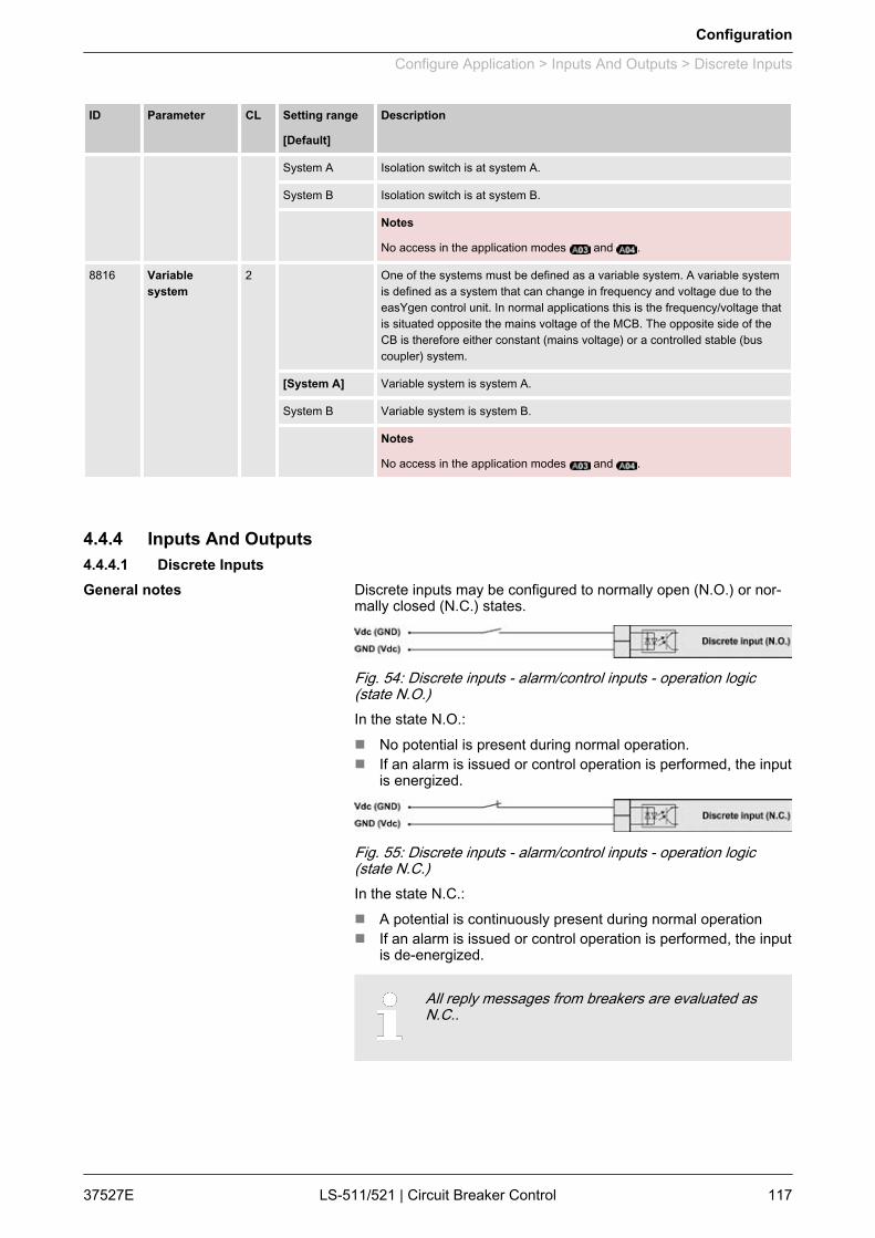
ID Parameter CL Setting range
[Default]
Description
System A Isolation switch is at system A.
System B Isolation switch is at system B.
Notes
No access in the application modes and .
8816 Variablesystem
2 One of the systems must be defined as a variable system. A variable systemis defined as a system that can change in frequency and voltage due to theeasYgen control unit. In normal applications this is the frequency/voltage thatis situated opposite the mains voltage of the MCB. The opposite side of theCB is therefore either constant (mains voltage) or a controlled stable (buscoupler) system.
[System A] Variable system is system A.
System B Variable system is system B.
Notes
No access in the application modes and .
4.4.4 Inputs And Outputs4.4.4.1 Discrete Inputs
Discrete inputs may be configured to normally open (N.O.) or nor‐mally closed (N.C.) states.
Fig. 54: Discrete inputs - alarm/control inputs - operation logic(state N.O.)In the state N.O.:n No potential is present during normal operation.n If an alarm is issued or control operation is performed, the input
is energized.
Fig. 55: Discrete inputs - alarm/control inputs - operation logic(state N.C.)In the state N.C.:n A potential is continuously present during normal operationn If an alarm is issued or control operation is performed, the input
is de-energized.
All reply messages from breakers are evaluated asN.C..
General notes
Configuration
Configure Application > Inputs And Outputs > Discrete Inputs
37527E LS-511/521 | Circuit Breaker Control 117

Alarm inputs may also be configured as control inputsand then be used as command variables in the Logi‐csManager.
Discrete input 8 is always used for the circuit breakerreplies and cannot be configured.
Number Terminal Assignment (all application modes)
[DI 01] 44 Alarm input (LogicsManager); pre-configured for 'Lock monitoring'
[DI 02] 45 Control input (LogicsManager); pre-configured for 'Remote acknowledge'
[DI 03] 46 Alarm input (LogicsManager); pre-configured for 'Enable decoupling'
[DI 04] 47 Alarm input (LogicsManager); pre-configured for 'Immediate open CBA'
[DI 05] 48 Control input (LogicsManager); pre-configured for 'Reply: Isolation switch is open'
[DI 06] 49 Control input (LogicsManager); pre-configured for 'Open CBA (with unloading)'
[DI 07] 50 Control input (LogicsManager); pre-configured for 'Enable to close CBA'
The following parameters are used to configure thediscrete inputs 1 through 7. The parameter IDs refer todiscrete input 1.– Refer to Ä “Discrete inputs - parameter IDs” Table
on page 118 for the parameter IDs of the parame‐ters DI 2 through DI 7.
DI 1 DI 2 DI 3 DI 4 DI 5 DI 6 DI 7
Text 1400 1410 1420 1430 1440 1450 1460
Operation 1201 1221 1241 1261 1281 1301 1321
Delay 1200 1220 1240 1260 1280 1300 1320
Alarm class 1202 1222 1242 1262 1282 1302 1322
Monitoringlockable
1203 1223 1243 1263 1283 1303 1323
Self acknowl‐edged
1204 1224 1244 1264 1284 1304 1324
Table 24: Discrete inputs - parameter IDs
Internal discrete inputs - terminalassignment
Parameter IDs
Configuration
Configure Application > Inputs And Outputs > Discrete Inputs
37527ELS-511/521 | Circuit Breaker Control118

ID Parameter CL Setting range
[Default]
Description
1400 DI {x} Text 2 user defined (4to 16 charac‐ters)
For default seeÄ Table on page 118
If the discrete input is enabled with alarm class, this text is displayed on thecontrol unit screen.
The event history will store this text message as well.
Notes
This parameter may only be configured using ToolKit.
If the DI is used as control input with the alarm class "Control", you may enterhere its function (e.g. external acknowledgement) for a better overview withinthe configuration.
1201 DI {x} Opera‐tion
2 The discrete inputs may be operated by an normally open (N.O.) or normallyclosed (N.C.) contact.
The idle circuit current input can be used to monitor for a wire break.
A positive or negative voltage polarity referred to the reference point of the DImay be applied.
[N.O.] The discrete input is analyzed as "enabled" by energizing the input (normallyopen).
N.C. The discrete input is analyzed as "enabled" by de-energizing the input (nor‐mally closed).
1200 DI {x} Delay 2 0.08 to 650.00 s
DI 01: [0.20 s]
DI 04: [0.20 s]
Other DIs: [0.50s]
A delay time in seconds can be assigned to each alarm or control input.
The discrete input must be enabled without interruption for the delay timebefore the unit reacts.
If the discrete input is used within the LogicsManager this delay is taken intoaccount as well.
1202 DI {x}Alarmclass
2 An alarm class may be assigned to the discrete input.
The alarm class is executed when the discrete input is enabled.
A/B Warning alarm classes
C/D/E/F Shutdown alarm classes
[Control] Signal to issue a control command only.
If "control" has been configured, there will be no entry in the event history anda function out of the LogicsManager (Ä Chapter 9.3.1 “LogicsManager Over‐view” on page 299) can be assigned to the discrete input.
1203 DI {x} Moni‐toring lockable
2 Yes Monitoring for fault conditions is only performed if "Lock Monitoring Status24.40" is false.
[No] Monitoring for this fault condition is continuously enabled regardless of "LockMonitoring Status 24.40".
1204 DI {x} Selfacknowledge
2 Yes The control automatically clears the alarm if the fault condition is no longerdetected.
Configuration
Configure Application > Inputs And Outputs > Discrete Inputs
37527E LS-511/521 | Circuit Breaker Control 119

ID Parameter CL Setting range
[Default]
Description
[No] The control does not automatically reset the alarm when the fault condition isno longer detected.
The alarm must be acknowledged and reset by manually pressing the appro‐priate buttons or by activating the LogicsManager output "External acknowl‐edgement" (via a discrete input or via an interface).
Notes
If the DI is configured with the alarm class "Control", self acknowledgement isalways active.
4.4.4.2 Discrete Outputs (LogicsManager)The discrete outputs are controlled via the LogicsManager.
For information on the LogicsManager and its defaultsettings see Ä Chapter 9.3.1 “LogicsManager Over‐view” on page 299.
Some outputs are assigned a function according to the applicationmode (see following table).
Relay Application
No. Terminal [R 01] 30/31 LogicsManager; pre-assigned with 'Ready for operation'
[R 02] 32/33 LogicsManager; pre-assigned with 'Centralized alarm (horn)'
[R 03] 34/35 LogicsManager; pre-assigned with 'System B not OK'
[R 04] 36/37 LogicsManager; pre-assigned with 'System A not OK'
[R 05] 38/39/40 Fixed to 'Open CBA'
[R 06] 41/42 Fixed to 'Close CBA' if CBA is controlled by 2 relays
otherwise LogicsManager pre-assigned with 'All Alarm classes'
Table 25: Relay outputs - assignment
CAUTION!Uncontrolled operation due to faulty configurationThe discrete output "Ready for operation OFF" mustbe wired in series with an emergency function.– Signal this fault independently of the unit if the
availability of the plant is important.
General notes
Configuration
Configure Application > Inputs And Outputs > Discrete Outputs (LogicsMa...
37527ELS-511/521 | Circuit Breaker Control120

ID Parameter CL Setting range
[Default]
Description
12580 Ready for op.Off
(Ready for oper‐ation OFF)
2 Determined byLogicsManager
The "Ready for operation OFF" relay is energized by default if the powersupply exceeds 8 V.
Once the conditions of the LogicsManager have been fulfilled, the relay willbe de-energized. This LogicsManager output may be configured with addi‐tional conditions, which may signal a PLC an "out of operation" condition byde-energizing the relay on terminals 30/31, like "shutdown alarm" or no"AUTO mode" present.
Notes
For information on the LogicsManager and its default settings seeÄ Chapter 9.3.1 “LogicsManager Overview” on page 299.
12110 Relay {x} 2 Determined byLogicsManager
Once the conditions of the LogicsManager have been fulfilled, the relay willbe energized.
Notes
For information on the LogicsManager and its default settings seeÄ Chapter 9.3.1 “LogicsManager Overview” on page 299.
The parameter ID above refers to relay 2.– Refer to Ä “Discrete outputs - relay parameter
IDs” Table on page 121 for the parameter IDs ofthe parameters for relay 3 to relay 6.
R 1 R 2 R 3 R 4 R 5 R 6
Parameter ID 12580 12110 12310 12320 12130 12140
Table 26: Discrete outputs - relay parameter IDs
4.4.5 Automatic RunID Parameter CL Setting range
[Default]
Description
8827 Startup inmode
(Operatingmode afterapplying thepower supply )
2 If the controller is powered down, the unit will start in the following configuredmode when it is powered up again.
[AUTO] The unit starts in the AUTOMATIC operating mode.
MAN The unit starts in the MANUAL operating mode.
Last The unit starts in the last operating mode the control was in prior to being de-energized.
Notes
No access in the application modes and .
Parameter IDs
Configuration
Configure Application > Automatic Run
37527E LS-511/521 | Circuit Breaker Control 121
ID Parameter CL Setting range
[Default]
Description
12510 Operat. modeAUTO
(Activate oper‐ating modeAUTOMATIC )
2 Determined byLogicsManager
[(0 & 1) & 1]
Once the conditions of the LogicsManager have been fulfilled the unit willchange into operating mode AUTOMATIC.
If AUTOMATIC mode is selected via the LogicsManager it is not possible tochange operating modes via the front panel.
Notes
No access in the application modes and .
For information on the LogicsManager and its default settings seeÄ Chapter 9.3.1 “LogicsManager Overview” on page 299.
12520 Operat. modeMAN
(Activate oper‐ating modeMANUAL)
2 Determined byLogicsManager
[(0 & 1) & 1]
Once the conditions of the LogicsManager have been fulfilled the unit willchange into operating mode MANUAL.
If MANUAL mode is selected via the LogicsManager it is not possible tochange operating modes via the front panel.
Notes
No access in the application modes and .
For information on the LogicsManager and its default settings seeÄ Chapter 9.3.1 “LogicsManager Overview” on page 299.
4.5 Configure Interfaces4.5.1 GeneralID Parameter CL Setting range
[Default]
Description
8051 Toolkit inter‐face
2 [Serial 1] Toolkit is working at Serial #1 interface (RS-232)
Serial 2 Toolkit is working at Serial #2 interface (RS-485)
4.5.2 CAN Interface
The CAN bus is a field bus and subject to various dis‐turbances. Therefore, it cannot be guaranteed thatevery request will be answered. We recommend torepeat a request, which is not answered within reason‐able time.
ID Parameter CL Setting range
[Default]
Description
9923 Comm. LS5 <->gen. device
2 The interface, which is used for transmitting the LS-5 data and easYgen loadshare data is configured here.
[CAN #1] Use CAN interface 1.
Off Deactivate interface.
General notes
Configuration
Configure Interfaces > CAN Interface
37527ELS-511/521 | Circuit Breaker Control122
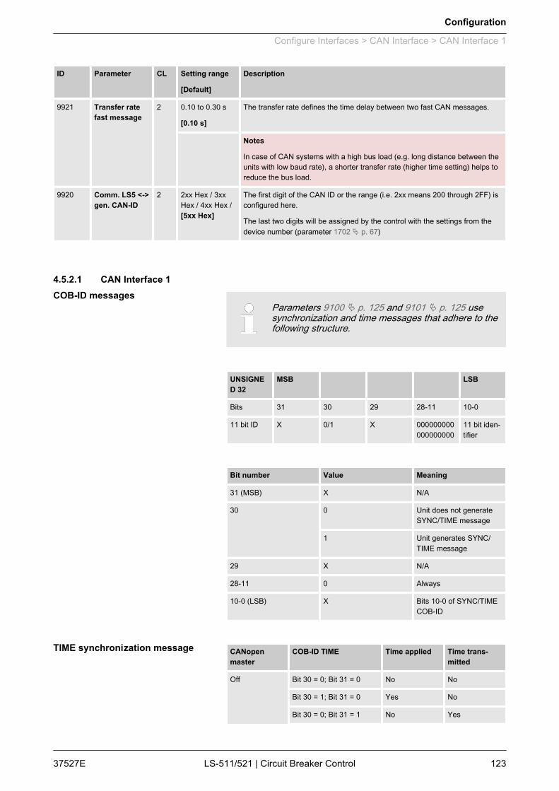
ID Parameter CL Setting range
[Default]
Description
9921 Transfer ratefast message
2 0.10 to 0.30 s
[0.10 s]
The transfer rate defines the time delay between two fast CAN messages.
Notes
In case of CAN systems with a high bus load (e.g. long distance between theunits with low baud rate), a shorter transfer rate (higher time setting) helps toreduce the bus load.
9920 Comm. LS5 <->gen. CAN-ID
2 2xx Hex / 3xxHex / 4xx Hex /[5xx Hex]
The first digit of the CAN ID or the range (i.e. 2xx means 200 through 2FF) isconfigured here.
The last two digits will be assigned by the control with the settings from thedevice number (parameter 1702 Ä p. 67)
4.5.2.1 CAN Interface 1
Parameters 9100 Ä p. 125 and 9101 Ä p. 125 usesynchronization and time messages that adhere to thefollowing structure.
UNSIGNED 32
MSB LSB
Bits 31 30 29 28-11 10-0
11 bit ID X 0/1 X 000000000000000000
11 bit iden‐tifier
Bit number Value Meaning
31 (MSB) X N/A
30 0 Unit does not generateSYNC/TIME message
1 Unit generates SYNC/TIME message
29 X N/A
28-11 0 Always
10-0 (LSB) X Bits 10-0 of SYNC/TIMECOB-ID
CANopenmaster
COB-ID TIME Time applied Time trans‐mitted
Off Bit 30 = 0; Bit 31 = 0 No No
Bit 30 = 1; Bit 31 = 0 Yes No
Bit 30 = 0; Bit 31 = 1 No Yes
COB-ID messages
TIME synchronization message
Configuration
Configure Interfaces > CAN Interface > CAN Interface 1
37527E LS-511/521 | Circuit Breaker Control 123

CANopenmaster
COB-ID TIME Time applied Time trans‐mitted
Bit 30 = 1; Bit 31 = 1 Yes Yes
Default Bit 30 = 0; Bit 31 = 0 No No
Bit 30 = 1; Bit 31 = 0 Yes No
Bit 30 = 0; Bit 31 = 1 No Yes1
Bit 30 = 1; Bit 31 = 1 Yes Yes1
On Bit 30 = 0; Bit 31 = 0 No No
Bit 30 = 1; Bit 31 = 0 Yes No
Bit 30 = 0; Bit 31 = 1 No Yes
Bit 30 = 1; Bit 31 = 1 Yes Yes
1 If CANopen master (lowest Node-ID).
ID Parameter CL Setting range
[Default]
Description
3156 Baudrate 2 20 / 50 / 100 /125 / 250 / 500 /800 / 1000kBaud
[250 kBd]
This parameter defines the used baud rate. Please note, that all participantson the CAN bus must use the same baud rate.
8950 Node-ID CANbus 1
2 1 to 127 (dec)
[33]
A number that is unique to the control must be set in this parameter so thatthis control unit can be correctly identified on the CAN bus.
This address number may only be used once on the CAN bus. All additionaladdresses are calculated based on this unique device number.
Notes
We recommend to configure the Node-IDs for units, which participate in loadsharing, as low as possible to facilitate establishing of communication.
No access in the application modes and .
8993 CANopenMaster
2 One bus participant must take over the network management and put theother participants into "operational" mode. The LS-5 is able to perform thistask.
[DefaultMaster]
The unit starts up in "operational" mode and sends a "Start_Remote_node"message after a short delay (the delay is the Node-ID (param‐eter 8950 Ä p. 124) in seconds, i.e. if the Node-ID is configured to 2, themessage will be sent after 2 seconds). If more than one easYgen / LS-5 isconfigured to Default Master, the unit with the lower Node-ID will take overcontrol. Therefore, the CAN bus devices, which are intended to act as DefaultMaster should be assigned a low Node-ID. No other device on the CAN bus(except the easYgens / LS-5s) may operate as Master).
On The unit is the CANopen Master and automatically changes into operationalmode and transmits data.
Off The unit is a CANopen Slave. An external Master must change into opera‐tional mode.
Configuration
Configure Interfaces > CAN Interface > CAN Interface 1
37527ELS-511/521 | Circuit Breaker Control124
ID Parameter CL Setting range
[Default]
Description
Notes
If this parameter is configured to "Off", the Master controller (for example aPLC) must send a "Start_Remote_node" message to initiate the load sharemessage transmission of the easYgen.
If no "Start_Remote_node" message would be sent, the complete systemwould not be operational.
9120 Producerheartbeat time
2 0 to 65500 ms
[2000 ms]
Independent from the CANopen Master configuration, the unit transmits aheartbeat message with this configured heartbeat cycle time.
If the producer heartbeat time is equal 0, the heartbeat will only be sent asresponse to a remote frame request. The time configured here will berounded up to the next 20 ms step.
9100 COB-ID SYNCMessage
2 1 to FFFFFFFFhex
[80 hex]
This parameter defines whether the unit generates the SYNC message ornot.
The message complies with CANopen specification: object 1005; subindex 0defines the COB-ID of the synchronization object (SYNC).
Notes
The structure of this object is shown in Ä “COB-ID messages” on page 123.
8940 ProducerSYNC Messagetime
2 0 to 65000 ms
[20 ms]
This is the cycle time of the SYNC message. If the unit is configured for thisfunction (parameter 9100 Ä p. 125) it will send the SYNC message with thisinterval. The time configured here will be rounded up to the next 10 ms step.
9101 COB-ID TIMEMessage
2 1 to FFFFFFFFhex
[100 hex]
This parameter defines whether the unit generates the TIME message or not.
Complies with CANopen specification: object 1012, subindex 0; defines theCOB-ID of the time object (TIME).
Notes
The structure of this object is shown in Ä “COB-ID messages” on page 123.
4.5.2.2 Additional Server SDOs (Service Data Objects)
The CAN bus is a field bus and subject to various dis‐turbances. Therefore, it cannot be guaranteed thatevery request will be answered. We recommend torepeat a request, which is not answered within reason‐able time.
The first Node-ID is the standard Node-ID of CAN interface 1(parameter 8950 Ä p. 124).
General notes
Configuration
Configure Interfaces > CAN Interface > Additional Server SDOs (S...
37527E LS-511/521 | Circuit Breaker Control 125

ID Parameter CL Setting range
[Default]
Description
33040 2. Node-ID 2 0 to 127 (dec)
[0]
In a multi-master application, each Master needs its own identifier (Node-ID)from the unit. in order to send remote signals (i.e. remote start, stop, oracknowledge) to the unit.
The additional SDO channel will be made available by configuring this Node-ID to a value different than zero. This is the additional CAN ID for the PLC.
33041 3. Node-ID 2 0 to 127 (dec)
[0]
In a multi-master application, each Master needs its own identifier (Node-ID)from the unit. in order to send remote signals (i.e. remote start, stop, oracknowledge) to the unit.
The additional SDO channel will be made available by configuring this Node-ID to a value different than zero. This is the additional CAN ID for the PLC.
33042 4. Node-ID 2 0 to 127 (dec)
[0]
In a multi-master application, each Master needs its own identifier (Node-ID)from the unit. in order to send remote signals (i.e. remote start, stop, oracknowledge) to the unit.
The additional SDO channel will be made available by configuring this Node-ID to a value different than zero. This is the additional CAN ID for the PLC.
33043 5. Node-ID 2 0 to 127 (dec)
[0]
In a multi-master application, each Master needs its own identifier (Node-ID)from the unit. in order to send remote signals (i.e. remote start, stop, oracknowledge) to the unit.
The additional SDO channel will be made available by configuring this Node-ID to a value different than zero. This is the additional CAN ID for the PLC.
4.5.2.3 Receive PDO 1 (Process Data Object)RPDO mapping is carried out as shown in (Fig. 56).
Fig. 56: RPDO mapping principle
Parameter 9300 Ä p. 127 uses communication param‐eters that adhere to the following structure.
General notes
COB-ID parameters
Configuration
Configure Interfaces > CAN Interface > Receive PDO 1 (Process Dat...
37527ELS-511/521 | Circuit Breaker Control126

UNSIGNED 32
MSB LSB
Bits 31 30 29 28-11 10-0
11 bit ID 0/1 X X 000000000000000000
11 bit iden‐tifier
Bit number Value Meaning
31 (MSB) 0 PDO exists / is valid
1 PDO does not exist / isnot valid
30 X N/A
29 X N/A
28-11 0 Always
10-0 (LSB) X Bits 10-0 of COB-ID
PDO valid / not valid allows to select, which PDOs areused in the operational state.
ID Parameter CL Setting range
[Default]
Description
9300 COB-ID 2 1 to FFFFFFFFhex
[80000000 hex]
This parameter contains the communication parameters for the PDOs, thedevice is able to receive.
Complies with CANopen specification: object 1400 (for RPDO 1, 1401 forRPDO 2 and 1402 for TPDO 3), subindex 1.
Notes
The structure of this object is shown in Ä “COB-ID parameters” on page 126.
Do not configure an RPDO or TPDO with a COB-ID higher than 580 (hex) orlower than 180 (hex). These IDs are reserved for internal purposes.
9121 Event-timer 2 0 to 65,500 ms
[2,000 ms]
This parameter configures the time, from which this PDO is marked as "notexisting". The time configured here will be rounded up to the next 5 ms step.Received messages are processed by the control unit every 20 ms. Mes‐sages, which are sent faster, will be discarded. We recommend to configureten times the cycle time of the received data here.
Notes
Complies with CANopen specification: object 1400 (for TPDO 1, 1401 forTPDO 2 and 1402 for TPDO 3), subindex 5
4.5.2.4 Transmit PDO {x} (Process Data Object)TPDO mapping is carried out as shown in (Fig. 57).General notes
Configuration
Configure Interfaces > CAN Interface > Transmit PDO {x} (Process ...
37527E LS-511/521 | Circuit Breaker Control 127
CANopen allows to send 8 byte of data with eachTransmit PDO. These may be defined separately if nopre-defined data protocol is used.All data protocol parameters with a parameter ID maybe sent as an object with a CANopen Transmit PDO.The data length will be taken from the data bytecolumn (see Ä Chapter 9.2 “Data Protocols”on page 243):– 1,2 UNSIGNED16 or SIGNED16– 3,4 UNSIGNED16 or SIGNED16– 5,6 UNSIGNED16 or SIGNED16– 1,2,3,4 UNSIGNED32 or SIGNED32– 3,4,5,6 UNSIGNED32 or SIGNED32– etc.The object ID is identical with the parameter ID whenconfiguring via front panel or ToolKit.
Parameters9600 Ä p. 129/9610 Ä p. 129/9620 Ä p. 129 use com‐munication parameters that adhere to the followingstructure.
UNSIGNED 32
MSB LSB
Bits 31 30 29 28-11 10-0
11 bit ID 0/1 X X 000000000000000000
11 bit iden‐tifier
Bit number Value Meaning
31 (MSB) 0 PDO exists / is valid
1 PDO does not exist / is notvalid
30 X N/A
29 X N/A
28-11 0 Always
10-0 (LSB) X Bits 10-0 of COB-ID
PDO valid / not valid allows to select, which PDOs areused in the operational state.
Fig. 57: TPDO mapping
COB-ID parameters
Configuration
Configure Interfaces > CAN Interface > Transmit PDO {x} (Process ...
37527ELS-511/521 | Circuit Breaker Control128

Parameters9602 Ä p. 129/9612 Ä p. 129/9622 Ä p. 129 are usedto select one of the following transmission types.
Transmis‐sion type
PDO transmission
Cyclic Acyclic Synchro‐nous
Asynchro‐nous
RTR only
0 Will not be sent
1-240 X X
241-251 Will not be sent
252 Will not be sent
253 Will not be sent
254 X
255 X
A value between 1 and 240 means that the PDO istransferred synchronously and cyclically. The transmis‐sion type indicating the number of SYNC, which arenecessary to trigger PDO transmissions.Receive PDOs are always triggered by the followingSYNC upon reception of data independent of thetransmission types 0 to 240. For TPDOs, transmissiontype 254 and 255 means, the application event is theevent timer.
ID Parameter CL Setting range
[Default]
Description
9600
9610
9620
COB-ID 2 1 to FFFFFFFFhex
[80000000 hex]
This parameter contains the communication parameters for the PDOs the unitis able to transmit. The unit transmits data (i.e. visualization data) on the CANID configured here.
Complies with CANopen specification: object 1800 for (TPDO 1, 1801 forTPDO 2 and 1802 for TPDO 3), subindex 1.
Notes
The structure of this object is shown in Ä “COB-ID parameters” on page 128
Do not configure an RPDO or TPDO with a COB-ID higher than 580 (hex) orlower than 180 (hex). These IDs are reserved for internal purposes.
9602
9612
9622
Transmissiontype
2 0 to 255
[255]
This parameter contains the communication parameters for the PDOs the unitis able to transmit. It defines whether the unit broadcasts all data automati‐cally (value 254 or 255) or only upon request with the configured address ofthe COB-ID SYNC message (parameter 9100 Ä p. 125).
Transmission types
Configuration
Configure Interfaces > CAN Interface > Transmit PDO {x} (Process ...
37527E LS-511/521 | Circuit Breaker Control 129

ID Parameter CL Setting range
[Default]
Description
Notes
Complies with CANopen specification: object 1800 (for TPDO 1, 1801 forTPDO 2 and 1802 for TPDO 3), subindex 2.
The description of the transmission type is shown in Ä “Transmission types” on page 129.
9604
9614
9624
Event timer 2 0 to 65500 ms
[20 ms]
This parameter contains the communication parameters for the PDOs the unitis able to transmit. The broadcast cycle for the transmitted data is configuredhere. The time configured here will be rounded up to the next 5 ms step.
Notes
Complies with CANopen specification: object 1800 (for TPDO 1, 1801 forTPDO 2 and 1802 for TPDO 3), subindex 5
8962
8963
8964
Selected DataProtocol
2 0 to 65535
8962: [5301]
8963: [0]
8964: [0]
A data protocol may be selected by entering the data protocol ID here. If 0 isconfigured here, the message assembled by the mapping parameters isused. If an unknown data protocol ID is configured here, a failure is indicatedby the CAN status bits.
Possible data protocol IDs are:
5301 Data telegram
9609
9619
9629
Number ofMappedObjects
2 0 to 4
[0]
This parameter contains the mapping for the PDOs the unit is able totransmit. This number is also the number of the application variables, whichshall be transmitted with the corresponding PDO.
Notes
Complies with CANopen specification: object 1A00 (for TPDO 1, 1A01 forTPDO 2 and 1A02 for TPDO 3), subindex 0
9605
9615
9625
1. MappedObject
2 0 to 65535
[0]
This parameter contains the information about the mapped application varia‐bles. These entries describe the PDO contents by their index. The sub-indexis always 1. The length is determined automatically.
Notes
Complies with CANopen specification: object 1A00 (for TPDO 1, 1A01 forTPDO 2 and 1A02 for TPDO 3), subindex 1
9606
9616
9626
2. MappedObject
2 0 to 65535
[0]
This parameter contains the information about the mapped application varia‐bles. These entries describe the PDO contents by their index. The sub-indexis always 1. The length is determined automatically.
Notes
Complies with CANopen specification: object 1A00 (for TPDO 1, 1A01 forTPDO 2 and 1A02 for TPDO 3), subindex 2
9607
9617
9627
3. MappedObject
2 0 to 65535
[0]
This parameter contains the information about the mapped application varia‐bles. These entries describe the PDO contents by their index. The sub-indexis always 1. The length is determined automatically.
Notes
Complies with CANopen specification: object 1A00 (for TPDO 1, 1A01 forTPDO 2 and 1A02 for TPDO 3), subindex 3
Configuration
Configure Interfaces > CAN Interface > Transmit PDO {x} (Process ...
37527ELS-511/521 | Circuit Breaker Control130

ID Parameter CL Setting range
[Default]
Description
9608
9618
9628
4. MappedObject
2 0 to 65535
[0]
This parameter contains the information about the mapped application varia‐bles. These entries describe the PDO contents by their index. The sub-indexis always 1. The length is determined automatically.
Notes
Complies with CANopen specification: object 1A00 (for TPDO 1, 1A01 forTPDO 2 and 1A02 for TPDO 3), subindex 4
4.5.3 RS-232 InterfaceID Parameter CL Setting range
[Default]
Description
3163 Baudrate 2 2.4 / 4.8 / 9.6 /14.4 / [19.2] /38.4 / 56 / 115kBaud
This parameter defines the baud rate for communications. Please note, thatall participants on the bus must use the same baud rate.
3161 Parity 2 [No] / Even /Odd
The used parity of the interface is set here.
3162 Stop bits 2 [One] / Two The number of stop bits is set here.
3185 ModBus SlaveID
2 0 to 255
[33]
The Modbus device address, which is used to identify the device via Modbus,is entered here.
If "0" is configured here, the Modbus is disabled.
3186 Reply delaytime
2 0.00 to 1.00 s
[0.00 s]
This is the minimum delay time between a request from the Modbus masterand the sent response of the slave.
This time is also required if an external interface converter to RS-485 is usedfor example.
4.5.4 RS-485 InterfaceID Parameter CL Setting range
[Default]
Description
3170 Baudrate 2 2.4 / 4.8 / 9.6 /14.4 / [19.2] /38.4 / 56 / 115kBaud
This parameter defines the baud rate for communications. Please note, thatall participants on the bus must use the same baud rate.
3171 Parity 2 [No] / Even /Odd
The used parity of the interface is set here.
3172 Stop bits 2 [One] / Two The number of stop bits is set here.
3188 ModBus SlaveID
2 0 to 255
[33]
The Modbus device address, which is used to identify the device via Modbus,is entered here.
If "0" is configured here, the Modbus is disabled.
3189 Reply delaytime
2 0.00 to 2.55 s
[0.00 s]
This is the minimum delay time between a request from the Modbus masterand the sent response of the slave. This time is required in halfduplex mode.
Configuration
Configure Interfaces > RS-485 Interface
37527E LS-511/521 | Circuit Breaker Control 131

4.5.5 Modbus Protocol (5300 Multiple)ID Parameter CL Setting range
[Default]
Description
3181 Power [W]exponent 10^x
2 2 to 5
[3]
This setting adjusts the format of the 16 bit power values in the data telegram.
Notes
For an example refer to Ä “Power measurement example” on page 132.
3182 Voltage [V]exponent 10^x
2 -1 to 2
[0]
This setting adjusts the format of the 16 bit voltage values in the data tele‐gram.
Notes
For an example refer to Ä “Voltage measurement example” on page 132.
3183 Current [A]exponent 10^x
2 -1 to 0
[0]
This setting adjusts the format of the 16 bit current values in the data tele‐gram.
Notes
For an example refer to Ä “Current measurement example” on page 133.
Refer to parameter 3181 Ä p. 132.
n The measurement range is 0…250 kWn Momentarily measurement value = 198.5 kW (198.500 W)
Setting Meaning Calculation Transfer value
(16Bit, max. 32767)
Possible displayformat
2 102 198500 W / 102 1985 198.5 kW
3 103 198500 W / 103 198 198 kW
4 104 198500 W / 104 9 N/A
5 105 198500 W / 105 1 N/A
Refer to parameter 3182 Ä p. 132.
Power measurement example
Voltage measurement example
Configuration
Configure Interfaces > Modbus Protocol (5300 Mult...
37527ELS-511/521 | Circuit Breaker Control132
n The measurement range is 0…480 Vn Momentarily measurement value = 477.8 V
Setting Meaning Calculation Transfer value
(16Bit, max. 32767)
Possible displayformat
-1 10-1 477.8 V / 10-1 4778 47.8 V
0 100 477.8 V / 100 477 477 V
1 101 477.8 V / 101 47 N/A
2 102 477.8 V / 102 4 N/A
Refer to parameter 3183 Ä p. 132.
n The measurement range is 0…500 An Momentarily measurement value = 345.4 A
Setting Meaning Calculation Transfer value
(16Bit, max. 32767)
Possible displayformat
-1 10-1 345.4 A / 10-1 3454 345.4 A
0 100 345.4 A / 100 345 345 A
4.6 Configure LogicsManagerThe LS-5 LogicsManager screens show logical symbols accordingto the IEC standard.
Refer to Ä Chapter 9.3.2 “Logical Symbols”on page 301 for a table of symbols according to thedifferent standards.
Internal flags within the LogicsManager logical outputs may be pro‐grammed and used for multiple functions.
Current measurement example
Logical symbols
Internal flags
Configuration
Configure LogicsManager
37527E LS-511/521 | Circuit Breaker Control 133

The flag parameters are listed as one entry in theparameter table below. For the parameter IDs of eachindividual flag parameter refer to Ä “Flag parameterIDs (1 to 8)” Table on page 134.
Flag {x} Flag 1 Flag 2 Flag 3 Flag 4 Flag 5 Flag 6 Flag 7 Flag 8
ParameterID yyyyy
12230 12240 12250 12260 12270 12280 12290 12300
Table 27: Flag parameter IDs (1 to 8)
Flag {x} Flag 9 Flag 10 Flag 11 Flag 12 Flag 13 Flag 14 Flag 15 Flag 16
ParameterID yyyyy
12910 12911 12912 12913 12914 12915 12916 12917
Table 28: Flag parameter IDs (9 to 16)
For conditions and explanation of programming pleaserefer to Ä Chapter 9.3.1 “LogicsManager Overview”on page 299.
Each LS-5 has five special flags (“Flag 1 LS5” to “Flag 5 LS5”)which can be defined via LogicsManager. They are transmitted viaCAN bus. These flags (26.01 to 27.80) are received by the otherLS-5 and easYgen devices and can be used as inputs for the Logi‐csManager
The command parameters are listed as one entry inthe parameter table below. For the parameter IDs ofeach individual command parameter refer to Ä “LS5flag parameter IDs” Table on page 134
Flag {x} LS-5 Flag 1 LS-5 Flag 2 LS-5 Flag 3 LS-5 Flag 4 LS-5 Flag 5 LS-5
Parameter ID yyyyy 12952 12953 12954 12955 12956
Table 29: LS5 flag parameter IDs
For conditions and explanation of programming pleaserefer to Ä Chapter 9.3.1 “LogicsManager Overview”on page 299.
Each LS-5 has eight LED flags ("LED 1" to "LED 8") which can bedefined via LogicsManager.
LS-5
LED
Configuration
Configure LogicsManager
37527ELS-511/521 | Circuit Breaker Control134

LED (internal) flags (24.51 to 24.58) within the LogicsManager log‐ical outputs may be programmed and used for multiple functions.
The LED configuration is used in the LS-51x to controlthe LEDs. In the LS-52x version the LED flags can beused as additional internal flags.
The flag parameters are listed as one entry in theparameter table below. For the parameter IDs of eachindividual flag parameter refer to Ä “LED flag param‐eter IDs” Table on page 135.
For conditions and explanation of programming pleaserefer to Ä Chapter 9.3.1 “LogicsManager Overview”on page 299.
LED {x} LED 1 LED 2 LED 3 LED 4 LED 5 LED 6 LED 7 LED 8
ParameterID yyyyy
12962 12963 12964 12965 12966 12967 12968 12969
Table 30: LED flag parameter IDs
Daily time setpointsUtilizing the LogicsManager it is possible to establishspecific times of the day that functions (i.e. generatorexerciser) can be enabled.The two daily time setpoints are activated each day atthe configured time. Using the LogicsManager thesesetpoints may be configured individually or combinedto create a time range.
Active time setpointUtilizing the LogicsManager it is possible to establishspecific days (or hours, minutes, seconds) that func‐tions (i.e. generator exerciser) can be enabled. Theactive switching point is activated only on a specifiedday (or hour, minute, second).The setpoints may be configured individually or com‐bined via the LogicsManager. You may configuremonthly, daily, hourly, minutely, or even secondly timesetpoints depending on how you combine the setpointsin the LogicsManager.
Timers
Configuration
Configure LogicsManager
37527E LS-511/521 | Circuit Breaker Control 135
Weekly time setpointUtilizing the LogicsManager it is possible to establishspecific days of the week that functions (i.e. generatorexerciser) can be enabled.The weekly time setpoint is enabled during the indi‐cated day from 0:00:00 hours to 23:59:59 hours.
ID Parameter CL Setting range
[Default]
Description
yyyyy Flag {x} 2 Determined byLogicsManager
[(0 & 1) & 1]
The flags may be used as auxiliary flags for complex combinations by usingthe logical output of these flags as command variable for other logical out‐puts.
For the corresponding IDs refer to Ä “LED flag parameter IDs” Tableon page 135.
yyyyy Flag {x} LS5 2 Determined byLogicsManager
[(0 & 1) & 1]
The flags may be used as auxiliary flags for complex combinations by usingthe logical output of these flags as command variable for other logical out‐puts.
For the corresponding IDs refer to Ä “LED flag parameter IDs” Tableon page 135.
yyyyy LED {x} 2 Determined byLogicsManager
LS-51x: The flags are used to control the LED states. The default values aredefined on the provided paper strip.
LS-52x: The flags may be used as auxiliary flags for complex combinationsby using the logical output of these flags as command variable for other log‐ical outputs.
For the corresponding IDs refer to Ä “LED flag parameter IDs” Tableon page 135.
1652
1657
Timer {x}: Hour 2 0 to 23 h
1652: [8 h]
1657: [17 h]
Enter the hour of the daily time setpoint here.
Example
n 0 = 0th hour of the day (midnight).n 23 = 23rd hour of the day (11pm).
1651
1656
Timer {x}:Minute
2 0 to 59 min
[0 min]
Enter the minute of the daily time setpoint here.
Example
n 0 = 0th minute of the hour.n 59 = 59th minute of the hour.
1650
1655
Timer {x}:Second
2 0 to 59 s
[0 s]
Enter the second of the daily time setpoint here.
Example
n 0 = 0th second of the minute.n 59 = 59th second of the minute.
Configuration
Configure LogicsManager
37527ELS-511/521 | Circuit Breaker Control136
ID Parameter CL Setting range
[Default]
Description
1663 Active day 2 Day 1 to 31
[1]
Enter the day of the active switch point here.
The active time setpoint is enabled during the indicated day from 0:00:00hours to 23:59:59 hours.
Example
n 01 = 1st day of the month.n 31 = 31st day of the month.
1662 Active hour 2 0 to 23 h
[12 h]
Enter the hour of the active switch point here.
The active time setpoint is enabled every day during the indicated hour fromminute 0 to minute 59.
Example
n 0 = 0th hour of the day.n 23 = 23rd hour of the day.
1661 Active minute 2 0 to 59 min
[0 min]
Enter the minute of the active switch point here.
The active time setpoint is enabled every hour during the indicated minutefrom second 0 to second 59.
Example
n 0 = 0th minute of the hour.n 59 = 59th minute of the hour.
1660 Active second 2 0 to 59 s
[0 s]
Enter the second of the active switch point here.
The active time setpoint is enabled every minute during the indicated second.
Example
n 0 = 0th second of the minute.n 59 = 59th second of the minute.
1670 Monday active 2 Please enter the days of the weekly workdays.
[Yes] The switch point is enabled every Monday.
No The switch point is disabled every Monday.
1671 Tuesday active 2 Please enter the days of the weekly workdays.
[Yes] The switch point is enabled every Tuesday.
No The switch point is disabled every Tuesday.
1672 Wednesdayactive
2 Please enter the days of the weekly workdays.
[Yes] The switch point is enabled every Wednesday.
No The switch point is disabled every Wednesday.
1673 Thursdayactive
2 Please enter the days of the weekly workdays.
[Yes] The switch point is enabled every Thursday.
No The switch point is disabled every Thursday.
1674 Friday active 2 Please enter the days of the weekly workdays.
[Yes] The switch point is enabled every Friday.
No The switch point is disabled every Friday.
1675 Saturdayactive
2 Please enter the days of the weekly workdays.
Configuration
Configure LogicsManager
37527E LS-511/521 | Circuit Breaker Control 137
ID Parameter CL Setting range
[Default]
Description
Yes The switch point is enabled every Saturday.
[No] The switch point is disabled every Saturday.
1676 Sunday active 2 Please enter the days of the weekly workdays.
Yes The switch point is enabled every Sunday.
[No] The switch point is disabled every Sunday.
4.7 Configure CountersID Parameter CL Setting range
[Default]
Description
2541 Counter valuepreset
2 0 to 65535
[0]
This parameter defines the number of times the control unit registers a CBAclosure. The number entered here will overwrite the current displayed valueafter confirming with parameter 2542 Ä p. 138.
2542 CBA setnumber of clo‐sures
2 Yes The current value of the CBA close counter is overwritten with the value con‐figured in "Counter value present". After the counter has been (re)set, thisparameter changes back to "No" automatically.
[No] The value of this counter is not changed.
Configuration
Configure Counters
37527ELS-511/521 | Circuit Breaker Control138
5 OperationThe LS-5 can be operated, monitored and configured using the fol‐lowing access methods:n Access via the front panel (LS-52x only)Ä Chapter 5.2 “Front Panel Access” on page 150
n External access with a PC using the ToolKit configuration soft‐ware.Ä Chapter 5.1 “Access Via PC (ToolKit)” on page 139
n External command access using Modbus/CANopen protocolsÄ Chapter 7 “Interfaces And Protocols” on page 225
5.1 Access Via PC (ToolKit)
Woodward’s ToolKit software is required to access theunit via PC.– Required version: 4.1.1 or higher– For information on how to obtain the latest version
see Ä “Load from the website” on page 140.
5.1.1 Install ToolKit
1. Insert the product CD (as supplied with the unit) in the CD-ROM drive of your computer.
ð The HTML menu is opened automatically in a browser.
The 'autostart' function of your operatingsystem needs to be activated.Alternately open the document "start.html" inthe root directory of the CD in a browser.
2. Go to section “Software” and follow the instructionsdescribed there.
Version
Load from CD
Fig. 58: Product CD - HTML menu
Fig. 59: HTML menu section 'Soft‐ware'
Operation
Access Via PC (ToolKit) > Install ToolKit
37527E LS-511/521 | Circuit Breaker Control 139
The latest version of the ToolKit software can beobtained from our website.
To get the software from the website:1. Go to http://www.woodward.com/software2. Select ToolKit in the list and click the “Go” button.3. Click “More Info” to get further information about ToolKit.4. Choose the preferred software version and click “Download” .5. Login with your e-mail address or register first.
ð The download will start immediatly.
n Microsoft Windows® 7, Vista, XP (32- & 64-bit); support for XPwill end on 2014-April-8
n Microsoft .NET Framework Ver. 4.0n 1 GHz Pentium® CPUn 512 MB of RAMn Screen
– Resolution: 800 by 600 pixels– Colors: 256
n Serial Portn Serial Extension Cablen IXXAT or Kvaser CAN adapter and drivern CD-ROM drive
Microsoft .NET Framework 4.0 must be installed onyour computer to be able to install ToolKit.– If not already installed, Microsoft .NET Framework
4.0 will be installed automatically (internet conec‐tion required).
– Alternatively use the .NET Framework 4.0 installerfound on the Product CD.
To install ToolKit:Run the self-extracting installation package and follow theon-screen steps to install.
Load from the website
Minimum system requirements
Installation
Operation
Access Via PC (ToolKit) > Install ToolKit
37527ELS-511/521 | Circuit Breaker Control140

5.1.2 Install ToolKit Configuration Files
1. Insert the product CD (as supplied with the unit) in the CD-ROM drive of your computer.
ð The HTML menu is opened automatically in a browser.
The 'autostart' function of your operatingsystem needs to be activated.Alternately open the document "start.html" inthe root directory of the CD in a browser.
2. Go to section “Configuration Files” and follow the instruc‐tions described there.
The latest version of the ToolKit software can beobtained from our website.
To get the software from the website:1. Go to http://www.woodward.com/software/configfiles2. Insert the part number (P/N) and revision of your device into
the corresponding fields.3. Select "ToolKit" in the “application type” list.4. Click “Search” .5. Download the file displayed in the search result.
ð The file is a ZIP archive which must be extracted for usein ToolKit.
Load from CD
Fig. 60: Product CD - HTML menu
Fig. 61: HTML menu section 'Soft‐ware'
Load from the website
Operation
Access Via PC (ToolKit) > Install ToolKit Configura...
37527E LS-511/521 | Circuit Breaker Control 141

*.WTOOL File name composition: [P/N1]1-[Revision]_[Language ID]_[P/N2]2-[Revision]_[# of visualized gens].WTOOL
Example file name: 8440-1234-NEW_US_5418-1234-NEW.WTOOL
File content: Display screens and pages for online configuration, which are associated with therespective *.SID file.
*.SID File name composition: [P/N2]2-[Revision].SID
Example file name: 5418-1234-NEW.SID
File content: All display and configuration parameters available in ToolKit.
*.WSET File name composition: [user defined].WSET
Example file name: device_settings.WSET
File content: Default settings of the ToolKit configuration parameters provided by the SID file or user-defined settings read from the unit.
n 1 P/N1 = Part number of the unitn 2 P/N2 = Part number of the software in the unit
ToolKit files
Operation
Access Via PC (ToolKit) > Install ToolKit Configura...
37527ELS-511/521 | Circuit Breaker Control142
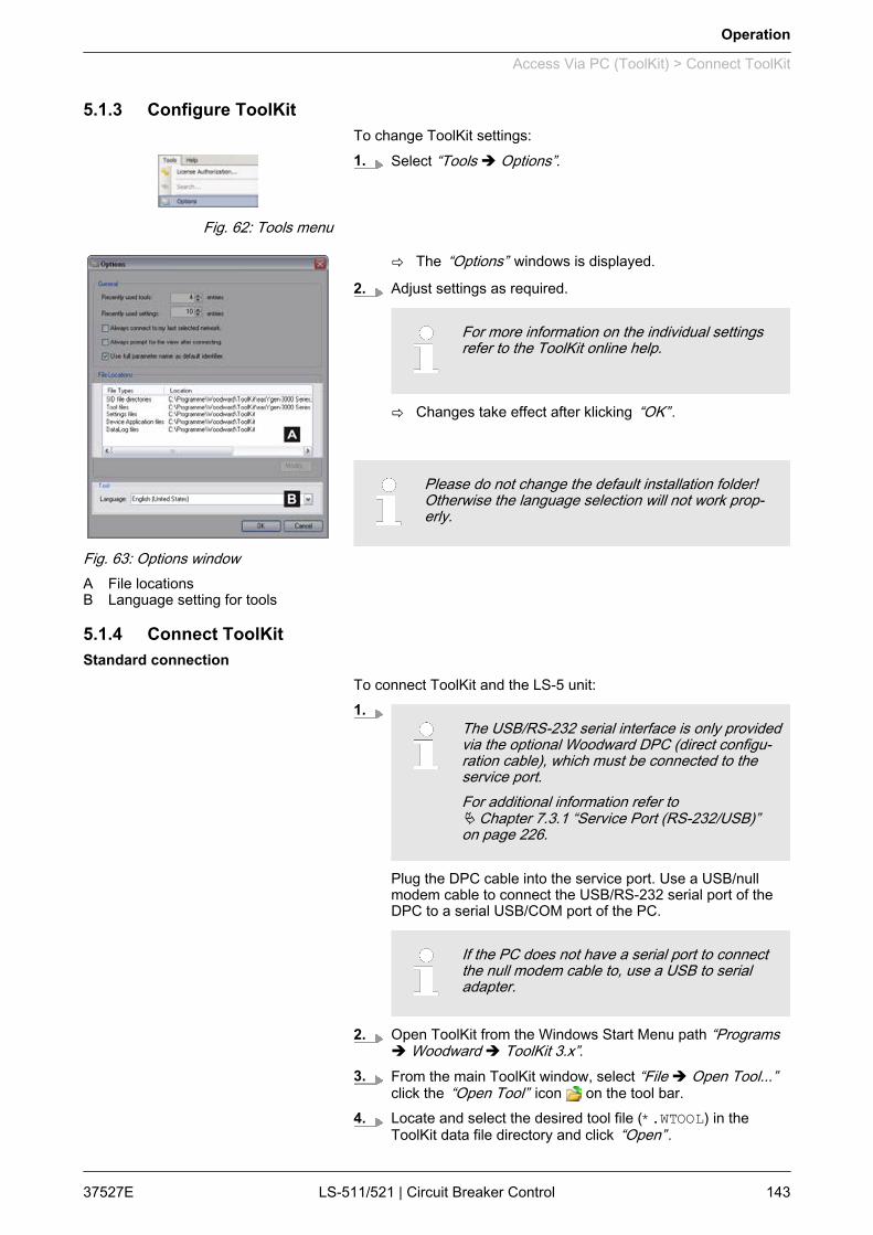
5.1.3 Configure ToolKitTo change ToolKit settings:1. Select “Tools è Options”.
ð The “Options” windows is displayed.
2. Adjust settings as required.
For more information on the individual settingsrefer to the ToolKit online help.
ð Changes take effect after klicking “OK” .
Please do not change the default installation folder!Otherwise the language selection will not work prop‐erly.
5.1.4 Connect ToolKit
To connect ToolKit and the LS-5 unit:1.
The USB/RS-232 serial interface is only providedvia the optional Woodward DPC (direct configu‐ration cable), which must be connected to theservice port.For additional information refer toÄ Chapter 7.3.1 “Service Port (RS-232/USB)”on page 226.
Plug the DPC cable into the service port. Use a USB/nullmodem cable to connect the USB/RS-232 serial port of theDPC to a serial USB/COM port of the PC.
If the PC does not have a serial port to connectthe null modem cable to, use a USB to serialadapter.
2. Open ToolKit from the Windows Start Menu path “Programsè Woodward è ToolKit 3.x”.
3. From the main ToolKit window, select “File è Open Tool...”click the “Open Tool” icon on the tool bar.
4. Locate and select the desired tool file (*.WTOOL) in theToolKit data file directory and click “Open” .
Fig. 62: Tools menu
Fig. 63: Options windowA File locationsB Language setting for tools
Standard connection
Operation
Access Via PC (ToolKit) > Connect ToolKit
37527E LS-511/521 | Circuit Breaker Control 143

5. From the main ToolKit window, click Device then click “Con‐nect”, or select the Connect icon on the toolbar.
ð The connect dialog will open if the option is enabled.
6. Select the COM port that is connected to the communicationcable.
7. Click the “Connect” button.
ð The identifier of the device that ToolKit is connected to,will display in the status bar.
Fig. 65: Communications window8. If the communications window opens, select
“ToolConfigurator” from the “Tool Device” list and close thecommunications window.
ð If the device is security enabled, the login dialog willappear.
9. Enter the login data if required.
ð Now you are able to edit the LS-5 parameters in the mainwindow.
Any changes are written automatically to thecontrol unit's memory after pressing [Enter]to confirm them..
It is also possible to connect to the unit via CAN bus, if a suitableCAN adapter is used.
We recommend to use the IXXAT USB-to-CAN con‐verter which must use the VCI V3 driver.
To connect ToolKit via CAN:1. Install the required drivers of the USB-to-CAN converter.2. Connect the unit.3. Open ToolKit and select a tool.4. Select “Connect” .5. Select the CAN connection in the “Connect” window.6. Configure the correct baud rate and timeout in the properties
dialog of the “Connect” window.
The Password for CAN Interface 1 (param‐eter 10402 Ä p. 67) must be entered before being ableto edit the parameters via CAN.
Fig. 64: Connect dialog
CAN bus connection
Operation
Access Via PC (ToolKit) > Connect ToolKit
37527ELS-511/521 | Circuit Breaker Control144
Fault description Cause RemedyConnection error (ToolKit freezeswhen trying to establish a connec‐tion)
Active connectionsvia infrared ports
Temporarily deactivate the infrared port(including virtual ports)
Active connectionsvia bluetooth
Temporarily deactivate bluetooth (includingvirtual ports)
Additional CANopendevices connected tothe bus
Contact Woodward support or providemissing .sid file for additional CANopendevice (Ä “SID files for additional CANopendevices” on page 145)
When connecting a PC to the LS-5 via CAN bus, other externalCANopen devices (like a Phoenix Contact I/O expansion board, forexample) may cause ToolKit to fail to connect.A cause may be that ToolKit looks for a SID file for the externaldevice, which does not exist.A special *.sid file can be created in this case.
For additional support feel free to contact Woodward.
n Create a SID (text) file with the following content: <?xml version="1.0" encoding="utf-8"?> <ServiceInterfaceDefinition xmlns:xsi="http://www.w3.org/ 2001/XMLSchema-instance" Identifier="[device application name]" Specification="EmptyFile"> </ServiceInterfaceDefinition>n Name the file [CANopen device identifier].sidn Store the file in the configured SID directory
CAN connection troubleshooting
SID files for additional CANopendevices
Operation
Access Via PC (ToolKit) > Connect ToolKit
37527E LS-511/521 | Circuit Breaker Control 145
5.1.5 View And Set Values In ToolKitToolKit offers the following graphical elements for basic navigation:
Graphical element Caption Description
Navigation buttons Select main and subordinate configura‐tion pages
Navigaton list To directly select a configuration pagebased on its name
Buttons “Previous page” and “Nextpage”
To go to the previous/next configurationpage (as ordered in the list)
Graphical element Caption Description
Value field To directly input (alpha)numeric values
Option field To select from a preset list of options
Connection status field Displays active port and unit connectionstatus
To change the value of a value or option field:1. Enter the value or select an option from the drop-down list.2. Press [Enter ] to confirm.
ð The new value is written directly to the unit.
Values displayed by visualization graphical elementscannot be changed.
Graphical element Caption Description
System setup visualization Displays breaker status
Warning indicator Displays status of warning alarms [on/off]
Error indicator Displays status of shutdown alarms[on/off]
Basic navigation
Value and status fields
Visualization
Operation
Access Via PC (ToolKit) > View And Set Values In Too...
37527ELS-511/521 | Circuit Breaker Control146

To find specific parameters, settings and monitoring values moreeasily, ToolKit includes a full-text search function.To find a parameter/setting/monitoring value:1. Select “Tools è Search” from the menu.
ð The “Search” dialog opens.
2. Enter a search term and press [Enter].ð The results are displayed in the table.
3. Double-click a table entry to go to the visualization/configura‐tion page that includes this parameter/setting/monitoringvalue.
The value trending view can chart up to eight values over time.To select values for trending screen:1. Right-click an analog value field on any configuration/visuali‐
sation page and select “Add to trend” from the context-menu.
2. Select “Tools è Trending” from the menu.
ð The trending screen opens.
3. Click the “Start” button to initiate charting.4. Click the “Stop” button to stop charting the values.5. To store the tracked data select “Export”
ð The tracked data is exported to a .CSV (comma sepa‐rated values) file which can be viewed/edited/analysed inexternal applications (e.g. MS Excel/OpenOffice.orgCalc).
Graphical element Caption Description
“Start” Start value charting
“Stop” Stop value charting
Zoom controls Adjust detail of value chart
“Export” Export to .CSV
“Properties” Change scale limits, sample rate, timespan, colors
5.1.6 Special ScreensThe following ToolKit screens provide overviews to the states ofconnected easYgen and LS-5 units in the network.
Search
Fig. 66: Search dialog
Value trending
Fig. 67: Trending screen
Operation
Access Via PC (ToolKit) > Special Screens
37527E LS-511/521 | Circuit Breaker Control 147

Fig. 68: States easYgen
Symbol Description
Operating mode STOP is active.
Operating mode MANUAL is active.
Operating mode AUTOMATIC is active.
Breaker is open.
Breaker is closed.
States easYgen
Operation
Access Via PC (ToolKit) > Special Screens
37527ELS-511/521 | Circuit Breaker Control148
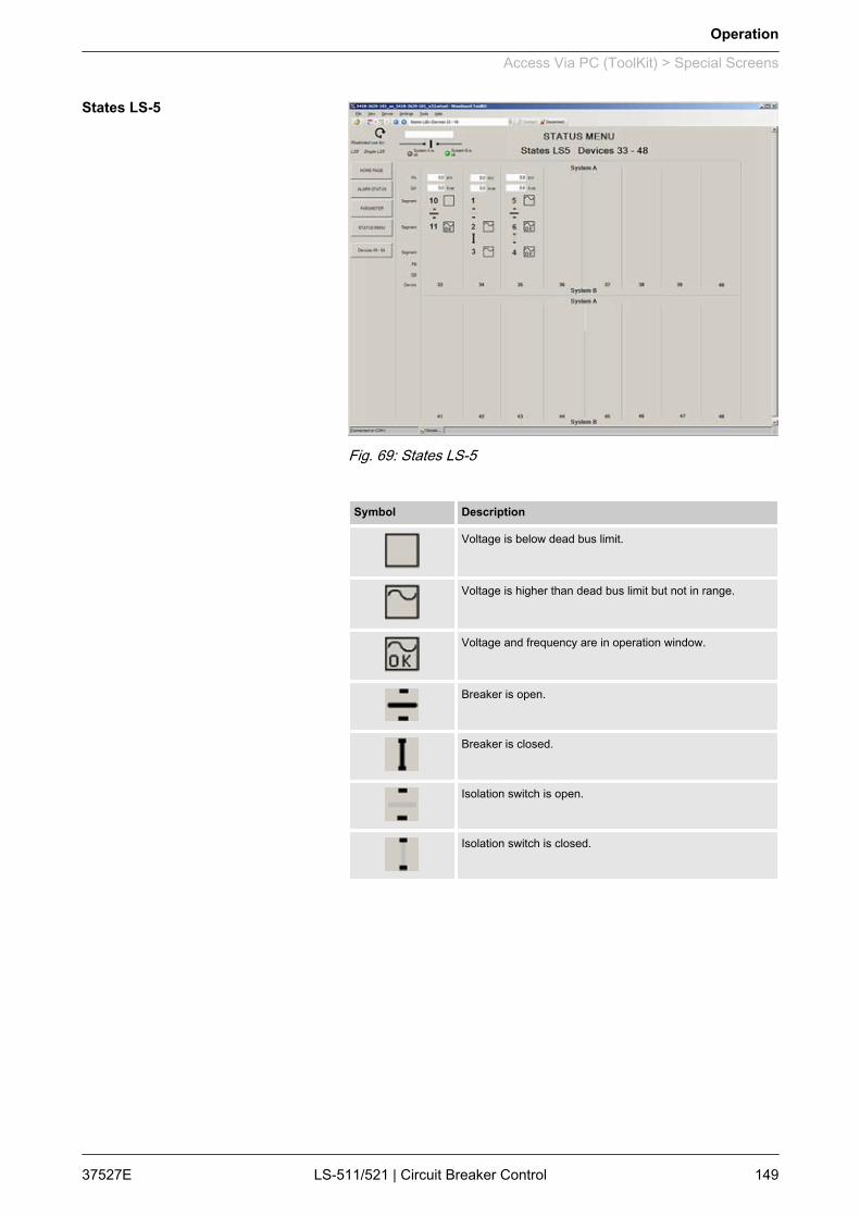
Fig. 69: States LS-5
Symbol Description
Voltage is below dead bus limit.
Voltage is higher than dead bus limit but not in range.
Voltage and frequency are in operation window.
Breaker is open.
Breaker is closed.
Isolation switch is open.
Isolation switch is closed.
States LS-5
Operation
Access Via PC (ToolKit) > Special Screens
37527E LS-511/521 | Circuit Breaker Control 149

5.2 Front Panel Access5.2.1 Basic Navigation
Fig. 70: Front panel and displayA (1..3) Button group "Hardware"B (4..6) Button group "Display" (Softkeys)C Button group "Navigation" (Softkeys)D (9..11) LEDs "Breaker/system states"Fig. 70 shows the front panel/display of the LS-52x with buttons,LEDs and LCD display. A short description of the front panel isgiven below.
No. Button Function (all screens)
1 Change into MANUAL operating mode. The LED indi‐cates that the operation mode is active.
When MANUAL is selected, breaker control is per‐formed manually via the button (No. 5).
If the control unit is configured to application mode or (parameter 8840 Ä p. 108) the button has
no function.
2 Change into AUTOMATIC operating mode. The LEDindicates that the operation mode is active.
When AUTOMATIC is selected, the control unit man‐ages all breaker control functions. These functionsare performed in accordance with how the control unitis configured.
3 Perform lamp test.
[A] Button group "Hardware"
Operation
Front Panel Access > Basic Navigation
37527ELS-511/521 | Circuit Breaker Control150
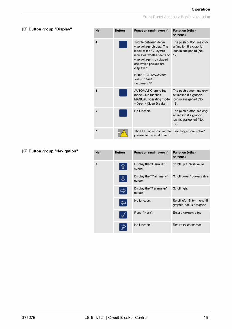
No. Button Function (main screen) Function (otherscreens)
4 Toggle between delta/wye voltage display. Theindex of the "V" symbolindicates whether delta orwye voltage is displayedand which phases aredisplayed.
Refer to Ä “Measuringvalues” Tableon page 157.
The push button has onlya function if a graphicicon is assigened (No.12).
5 AUTOMATIC operatingmode – No function.MANUAL operating mode– Open / Close Breaker.
The push button has onlya function if a graphicicon is assigened (No.12).
6 No function. The push button has onlya function if a graphicicon is assigened (No.12).
7 The LED indicates that alarm messages are active/present in the control unit.
No. Button Function (main screen) Function (otherscreens)
8 Display the "Alarm list"screen.
Scroll up / Raise value
Display the "Main menu"screen.
Scroll down / Lower value
Display the "Parameter"screen.
Scroll right
No function. Scroll left / Enter menu (ifgraphic icon is assigned
Reset "Horn". Enter / Acknowledge
No function. Return to last screen
[B] Button group "Display"
[C] Button group "Navigation"
Operation
Front Panel Access > Basic Navigation
37527E LS-511/521 | Circuit Breaker Control 151
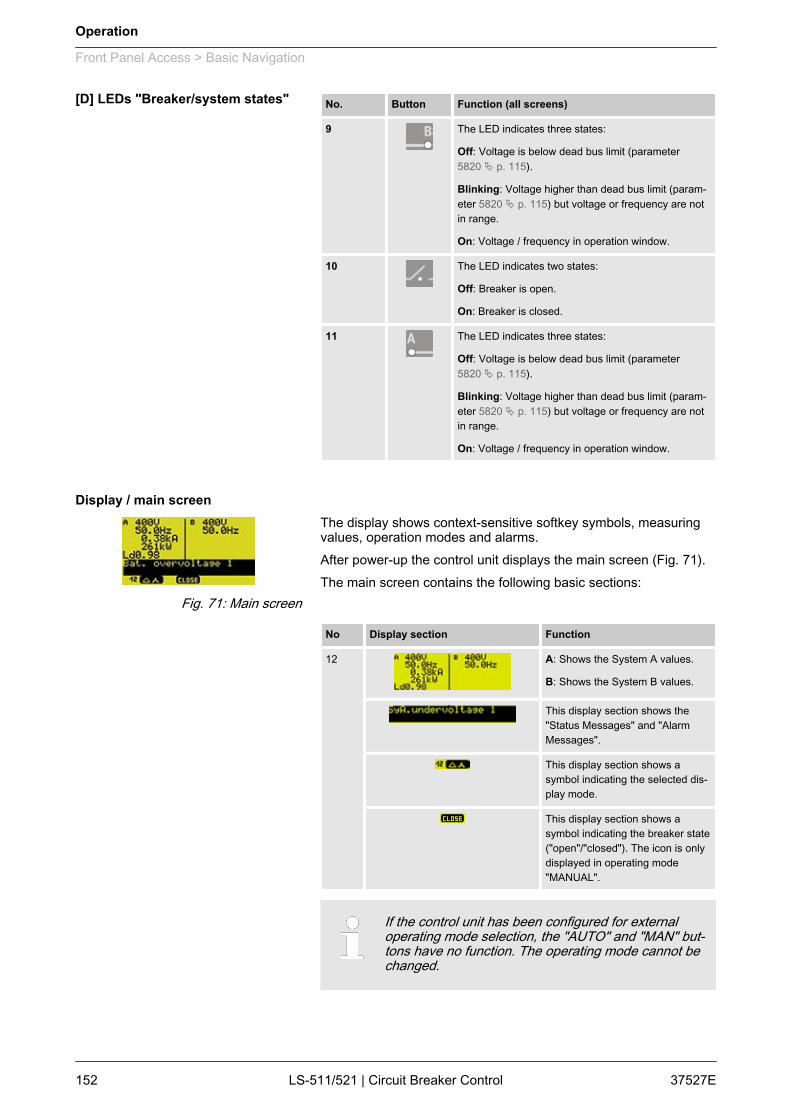
No. Button Function (all screens)
9 The LED indicates three states:
Off: Voltage is below dead bus limit (parameter5820 Ä p. 115).
Blinking: Voltage higher than dead bus limit (param‐eter 5820 Ä p. 115) but voltage or frequency are notin range.
On: Voltage / frequency in operation window.
10 The LED indicates two states:
Off: Breaker is open.
On: Breaker is closed.
11 The LED indicates three states:
Off: Voltage is below dead bus limit (parameter5820 Ä p. 115).
Blinking: Voltage higher than dead bus limit (param‐eter 5820 Ä p. 115) but voltage or frequency are notin range.
On: Voltage / frequency in operation window.
The display shows context-sensitive softkey symbols, measuringvalues, operation modes and alarms.After power-up the control unit displays the main screen (Fig. 71).The main screen contains the following basic sections:
No Display section Function
12 A: Shows the System A values.
B: Shows the System B values.
This display section shows the"Status Messages" and "AlarmMessages".
This display section shows asymbol indicating the selected dis‐play mode.
This display section shows asymbol indicating the breaker state("open"/"closed"). The icon is onlydisplayed in operating mode"MANUAL".
If the control unit has been configured for externaloperating mode selection, the "AUTO" and "MAN" but‐tons have no function. The operating mode cannot bechanged.
[D] LEDs "Breaker/system states"
Display / main screen
Fig. 71: Main screen
Operation
Front Panel Access > Basic Navigation
37527ELS-511/521 | Circuit Breaker Control152

The softkeys (Fig. 70/B) permit navigation between screens, levelsand functions as well as configuration and operation.
Softkey symbol Caption Description
Increase Increase value.
Decrease Decrease value.
Help Access help screen.
Toggle Toggle between the configurable elements.
Reset Reset the maximum value display.
Menu screen Symbol Description
Alarm List Indicates that corresponding alarm condition is still present.
States easYgen STOP operating mode.
MANUAL operating mode.
AUTOMATIC operating mode.
Breaker open (GCB).
Breaker closed (GCB).
Segment number.
Device number.
States LS-5 Segment numbers and breaker open.
Segment numbers and breaker closed.
Segment numbers and isolation switch open.
Segment numbers and isolation switch closed.
Indicates voltage and frequency are in range.
Indicates voltage or frequency are not in range.
Own LS-5 device number.
Other LS-5 device numbers.
Various Screens Variable is TRUE (LogicsManager).
The bit is enabled (CAN interface).
Relay activated (Discrete outputs)
Variable is FALSE (LogicsManager).
The bit is disabled (CAN interface).
Relay deactivated (Discrete outputs)
Softkeys
Status symbols
Operation
Front Panel Access > Basic Navigation
37527E LS-511/521 | Circuit Breaker Control 153

Fig. 72: Menu structure
The following chapters list notes on specific menuscreens.For information on standard softkeys and status sym‐bols refer to Ä Chapter 5.2.1 “Basic Navigation”on page 150.
Menu structure
Operation
Front Panel Access > Basic Navigation
37527ELS-511/521 | Circuit Breaker Control154
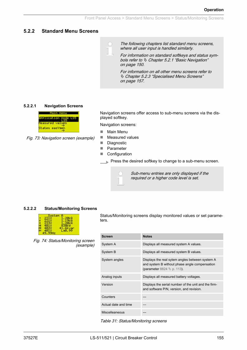
5.2.2 Standard Menu Screens
The following chapters list standard menu screens,where all user input is handled similarly.For information on standard softkeys and status sym‐bols refer to Ä Chapter 5.2.1 “Basic Navigation”on page 150.For information on all other menu screens refer toÄ Chapter 5.2.3 “Specialised Menu Screens”on page 157.
5.2.2.1 Navigation ScreensNavigation screens offer access to sub-menu screens via the dis‐played softkey.Navigation screens:n Main Menun Measured valuesn Diagnosticn Parametern Configuration
Press the desired softkey to change to a sub-menu screen.
Sub-menu entries are only displayed if therequired or a higher code level is set.
5.2.2.2 Status/Monitoring ScreensStatus/Monitoring screens display monitored values or set parame‐ters.
Screen Notes
System A Displays all measured system A values.
System B Displays all measured system B values.
System angles Displays the real sytem angles between system Aand system B without phase angle compensation(parameter 8824 Ä p. 113).
Analog inputs Displays all measured battery voltages.
Version Displays the serial number of the unit and the firm-and software P/N, version, and revision.
Counters ---
Actual date and time ---
Miscelleaneous ---
Table 31: Status/Monitoring screens
Fig. 73: Navigation screen (example)
Fig. 74: Status/Monitoring screen(example)
Operation
Front Panel Access > Standard Menu Screens > Status/Monitoring Screens
37527E LS-511/521 | Circuit Breaker Control 155

Unit Value
V Voltage
A Current
kW Real power
Kvar Reactive power
Hz Frequency
Lg Lagging
Ld Leading
Table 32: Units of measured values
5.2.2.3 Value Setting Screens
Screen Notes
Application mode LS-5 Set the current application mode.
Display configuration Allows the display contrast to be configured.
Enter password Allows the password to be entered for a specific codelevel.
Application configuration ---
Monitoring configuration ---
Measurement configura‐tion
---
Interfaces configuration ---
Counters configuration ---
Language clock configu‐ration
---
System Management ---
Table 33: Value setting screens
Use the following buttons in a value setting screen to select,change and confirm a setting.
Button/Softkey Description
Select previous value/entry.
Select next value/entry.
/ Increase selected value.
/ Decrease selected value.
Confirm and store changed value.
Return without any changes.
Fig. 75: Value setting screen(example)
Operation
Front Panel Access > Standard Menu Screens > Value Setting Screens
37527ELS-511/521 | Circuit Breaker Control156

5.2.3 Specialised Menu Screens5.2.3.1 Main Screen Voltage Display
The voltage display softkey on the main screen changes the typeof voltage display.
The amount of information available from the systemdepends on how the measuring is configured in thecontrol unit.
The following tables illustrate what values are available dependingon the configured measurement type:
Press:
Symbol Displayedvoltage
Displayed at parameter setting
3Ph4W 3Ph3W 1Ph2W 1Ph3W
0× (6×) Delta L1-L2 Yes Yes Yes1 ---
1× Delta L2-L3 Yes Yes --- ---
2× Delta L3-L1 Yes Yes --- Yes
3× Wye L1-N Yes --- Yes1 Yes
4× Wye L2-N Yes --- --- ---
5× Wye L3-N Yes --- --- Yes
Table 34: Measuring values
1 depends on setting of parameter 1858 Ä p. 70.
5.2.3.2 Alarm ListAll alarm messages, which have not been acknowledged andcleared, are displayed. Each alarm is displayed with the alarmmessage and the date and time of the alarm occurred in the formatyy-mon-dd hh:mm:ss.ss.
Self-acknowledging alarm messages get a new time‐stamp when initializing the unit (switching on).
A maximum of 16 alarm messages can be displayed. If16 alarm messages are already displayed and furtheralarm messages occur, these will not be displayedbefore displayed alarm messages are acknowledgedand thus deleted from the list.
Fig. 76: Alarm List screen
Operation
Front Panel Access > Specialised Menu Screens > Alarm List
37527E LS-511/521 | Circuit Breaker Control 157

Symbol/Button Description
Indicates that corresponding alarm condition is still present.
Acknowledge the selected alarm message (displayedinverted).
Acknowledgement is only possible, if the alarm condi‐tion is no longer present. If the Alarm LED is stillflashing (an alarm is present, which has not yet beenacknowledged as 'Seen'), this softkey resets the hornand acknowledges the alarm as 'Seen'.
5.2.3.3 SynchroscopeThe square symbol indicates the actual phase angle betweensystem A and system B. A complete left position of the squaresymbol means -180° and complete right position means +180°.The frequency and voltage differences are indicated in the display.
The shown value is not the real angle between systemA and system B if the phase angle compensation(parameter 8824 Ä p. 113) is active. The configuredphase angle compensation is added to the angle.
Symbol/Button Description
Indicates the actual phase angle between system A andsystem B.
5.2.3.4 LogicsManager ConditionsThis screen displays the conditions of all LogicsManager commandvariables, which are located in their respective groups.
Symbol/Button Description
Select the highlighted command variable group and displaythe state of the command variables in this group.
Variable is TRUE.
Variable is FALSE.
Fig. 77: Synchroscope screen LS-5
Fig. 78: LogicsManager conditionsscreen
Fig. 79: Command variables screen(example)
Operation
Front Panel Access > Specialised Menu Screens > LogicsManager Conditions
37527ELS-511/521 | Circuit Breaker Control158
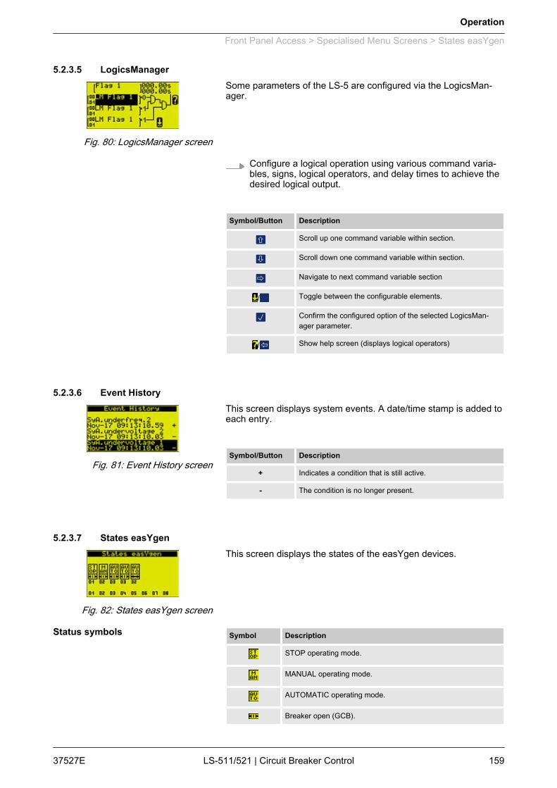
5.2.3.5 LogicsManagerSome parameters of the LS-5 are configured via the LogicsMan‐ager.
Configure a logical operation using various command varia‐bles, signs, logical operators, and delay times to achieve thedesired logical output.
Symbol/Button Description
Scroll up one command variable within section.
Scroll down one command variable within section.
Navigate to next command variable section
/ Toggle between the configurable elements.
Confirm the configured option of the selected LogicsMan‐ager parameter.
/ Show help screen (displays logical operators)
5.2.3.6 Event HistoryThis screen displays system events. A date/time stamp is added toeach entry.
Symbol/Button Description
+ Indicates a condition that is still active.
- The condition is no longer present.
5.2.3.7 States easYgenThis screen displays the states of the easYgen devices.
Symbol Description
STOP operating mode.
MANUAL operating mode.
AUTOMATIC operating mode.
Breaker open (GCB).
Fig. 80: LogicsManager screen
Fig. 81: Event History screen
Fig. 82: States easYgen screen
Status symbols
Operation
Front Panel Access > Specialised Menu Screens > States easYgen
37527E LS-511/521 | Circuit Breaker Control 159

Symbol Description
Breaker closed (GCB).
Segment number.
Device number.
5.2.3.8 States LS-5This screen displays the states of the LS-5 devices.
Symbol Description
Segment numbers and breaker open.
Segment numbers and breaker closed.
Segment numbers and isolation switch open.
Segment numbers and isolation switch closed.
Indicates voltage and frequency are in range.
Indicates voltage or frequency are not in range.
Own LS-5 device number.
Other LS-5 device numbers.
5.2.3.9 Discrete Inputs/OutputsThis screen displays discrete inputs' and discrete outputs' status.
The configured logic for the discrete input "N.O./N.C."will determine how the LS-5 reacts to the state of thediscrete input. If the respective DI is configured to N.O,the unit reacts on the energized state; if it is configuredto N.C., it reacts on the de-energized state.
Type Symbol State
Input energized
de-energized
Output relay activated
relay de-activated
Fig. 83: States LS-5 screen
Status symbols
Fig. 84: Discrete inputs/outputsscreen
Operation
Front Panel Access > Specialised Menu Screens > Discrete Inputs/Outputs
37527ELS-511/521 | Circuit Breaker Control160

5.2.3.10 CAN Interface 1 State
Symbol Description
TRUE/enabled The bit is enabled.
FALSE/disabled The bit is disabled.
Section Bit Assignment
Can bus 1 state 1 A TPDO has incorrect mapping parameters
3 A TPDO has more than 8 bytes
CAN 1 monitoring (active state) {x} RPDO {x} is not received at the moment
CAN 1 monitoring (latched state) {x} RPDO {x} has not been received
Table 35: Bit assigments
5.3 Restore Language SettingDue to the multilingual capability of the unit, it may happen that thedisplay language of the LS-5 is set to a language, the operator isunable to read or understand.In this case, the following proceeding helps to restore the desiredlanguage.
The default setting is English.
In order to change the language setting, press the softkeys in thefollowing order:
Fig. 85: CAN interface state screen(example)
Operation
Restore Language Setting
37527E LS-511/521 | Circuit Breaker Control 161
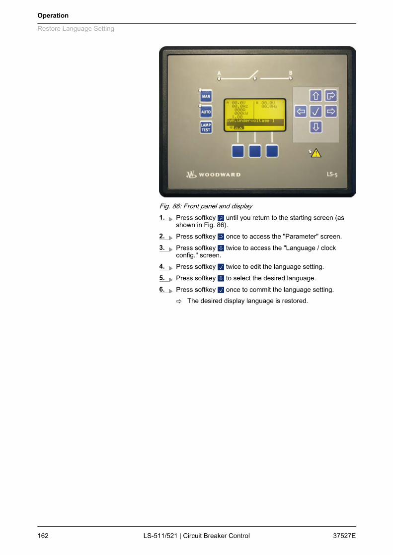
Fig. 86: Front panel and display1. Press softkey until you return to the starting screen (as
shown in Fig. 86).2. Press softkey once to access the "Parameter" screen.3. Press softkey twice to access the "Language / clock
config." screen.4. Press softkey twice to edit the language setting.5. Press softkey to select the desired language.6. Press softkey once to commit the language setting.
ð The desired display language is restored.
Operation
Restore Language Setting
37527ELS-511/521 | Circuit Breaker Control162

6 Application6.1 Application Modes Overview
The LS-5 circuit breaker control units are designed to enable com‐plex power management applications with multiple incoming mainsand bus breakers in combination with easYgen-3400/3500equipped genset controllers.This device combination allows to establish various applications.To make the handling for that wide range of applications easier,different preconfigured application modes in the LS-5 as well in theeasYgen-3400/3500 are provided.These application modes are created because some preconfigura‐tions are automatically fixed through the according applicationmodes. The following chapter explains the differentiation of theapplication modes and there settings.
Not all possible configurations can be explained indetail, but shall help to guide through the settingsaccording to the mode.
The control units can be used stand-alone (Ä Chapter 6.1.1 “LS-5:Stand-Alone Application Mode” on page 164) or common applica‐tions with Woodward easYgen-3400/3500 genset control units(Ä Chapter 6.1.2 “LS-5 & easYgen-3400/3500: Common Applica‐tion Modes (LS-5 View)” on page 164 and Ä Chapter 6.1.3“easYgen-3400/3500 & LS-5: Common Application Modes(easYgen-3400/3500 View)” on page 166).
For detailed information on the application modes,notes on safety and examples of special applicationsrefer to the following chapters:– Ä Chapter 6.2 “Setup Stand-Alone Applications
(Mode A01)” on page 168– Ä Chapter 6.3 “Setup easYgen & Slave LS-5
Applications (Mode A03 & A04)” on page 171– Ä Chapter 6.4 “Setup easYgen & Independent
LS-5 Applications (Mode A02)” on page 189
Mode LS-5 Symbol Mode easYgen Symbol
LS-5 Single LS5 N/A N/A
LS-5 & easYgen LS5 (up to 16 unit) GCB/LS5
L-MCB (max. 1 unit) GCB/L-MCB
GCB/GGB/L-MCB
L-GGB (max. 1 unit) GCB/L-GGB
L-GGB (max. 1 unit) GCB/L-GGB/L-MCB
L-MCB (max. 1 unit)
General notes
Correlating application modes
Application
Application Modes Overview
37527E LS-511/521 | Circuit Breaker Control 163
6.1.1 LS-5: Stand-Alone Application Mode
LS-511/521 easYgen-3400/3500 Mode Symbol Mode Symbol Function
Single LS5 None None Independent synch check relay mode.
This application mode provides the following functions:
n Handling of CBA (dead bus closure, synchronization, open) intitiatedby the corresponding command variables or by manual commands.
n Measuring and monitoring of system A values (voltage, frequency,phase rotation, current).
n Measuring of system B values (voltage, frequency, phase rotation).n Measuring of active and reactive power on system A.n Measuring of phase angle system A to system B.n Interacting as an independent synchronizer for a PLC by communi‐
cation interface (CANopen, Modbus RTU slave).
6.1.2 LS-5 & easYgen-3400/3500: Common Application Modes (LS-5 View)
For information on the easYgen genset control unit'sapplication modes refer to the easYgen manual.
LS-511/521 easYgen-3400/3500 Mode Symbol Mode Symbol Function
LS5 GCB/LS5 Open LS-5 system, in combination with easYgen-3400/3500, individuallyconfigurable.
This application mode provides the following functions:
n Handling of CBA (dead bus closure, synchronization, open) intitiatedby the corresponding command variables or by manual commands.
n Measuring and monitoring of system A values (voltage, frequency,phase rotation, current).
n Measuring of system B values (voltage, frequency, phase rotation).n Measuring of active and reactive power on system A.n Measuring of phase angle system A to system B.n Recognition of segments within the easYgen / LS-5 system.n Dead bus arbitration with other easYgen and LS-5.n Mains decoupling function in the LS-5 configurable, for LS-5 con‐
nected with system A at mains.
L-MCB GCB/L-MCB LS-5 as MCB control in combination with easYgen-3400/3500 in a fixedapplication.
This application mode provides the following functions:
n Handling of a MCB (dead bus closure, synchronization, open) intiti‐ated by the easYgen.
n Measuring and monitoring of system A values, (mains voltage,mains frequency, mains phase rotation, mains current), transferredto easYgen.
Application
Application Modes Overview > LS-5 & easYgen-3400/3500: ...
37527ELS-511/521 | Circuit Breaker Control164
LS-511/521 easYgen-3400/3500 Mode Symbol Mode Symbol Function
GCB/GGB/L-MCB
n Measuring of system B values, (voltage, frequency, phase rotation),transferred to easYgen.
n Measuring of mains active and mains reactive power on system A.n Automatic configuration of the relevant parameters.n Mains decoupling function in the LS-5 configurable.
L-GGB GCB/L-GGB LS-5 as GGB control in combination with easYgen-3400/3500 in a fixedapplication.
This application mode provides the following functions:
n Handling of a GGB (dead bus closure, synchronization, open) intiti‐ated by the easYgen.
n Measuring and monitoring of system A values (load voltage, loadfrequency, load phase rotation).
n Measuring of system B values (generator busbar voltage, -fre‐quency, -phase rotation).
n Automatic configuration of the relevant parameters.
Application
Application Modes Overview > LS-5 & easYgen-3400/3500: ...
37527E LS-511/521 | Circuit Breaker Control 165
6.1.3 easYgen-3400/3500 & LS-5: Common Application Modes (easYgen-3400/3500View)
easYgen-3400/3500 LS-511/521 Mode Symbol Mode Symbol Function
GCB/LS5 LS5 One or more easYgen in combination with an open LS-5 system, individ‐ually configurable for different application. Multiple isolated and/or mainsparallel operation. (max. 16 LS-5).
This application mode provides the following functions:
n Handling of the GCB (dead bus closure, synchronization, open) inti‐tiated by start command in AUTO or individually in MAN mode.
n Measuring and monitoring of generator values (voltage, frequency,phase rotation, current and power).
n Measuring of generator busbar values (voltage, frequency).n Indicating of mains values (voltage, frequency) sent from 'Mains'-
LS-5 with the smallest ID in the own segment.n Indicating the sum of active and reactive power sent from all 'Mains'-
LS-5 in the own segment.n Regulating Import/Export power with the sum of active and reactive
power sent from all 'Mains'-LS-5 in the own segment.n The easYgen recognizes through the LS-5 system the active seg‐
ment number.n Connection to mains (MCB is closed) is recognized via the LS-5
system, if one or more “Mains”-LS-5 are available.n The close and open commands for the single LS-5 breakers are
usually not generated in the easYgen.n Mains voltage and current is usually not connected at the easYgen.n Run-up synchronization, acting on the GCB, is possible.
GCB/L-MCB L-MCB One or more easYgen in combination with one LS-5 unit, acting on theMCB in a fixed application. Multiple isolated and/or mains parallel opera‐tion. The same handling as in the GCB/MCB mode, but the MCB is oper‐ated through the LS5.
This application mode provides the following functions:
n Handling of the GCB (dead bus closure, synchronization, open) inti‐tiated by start command in AUTO or individually in MAN mode.
n Handling of the MCB (dead bus closure, synchronization, open) inAUTO and MANUAL according to the rules of the GCB/MCB mode.
n Measuring and monitoring of generator values (voltage, frequency,phase rotation, current and power)
n Measuring of generator busbar values (voltage, frequency)n Indicating of mains values (voltage, frequency, phase angle) sent
from the LS-5.n Indicating of active and reactive power at the interchange point sent
from LS-5.n Regulating Import/Export power with active and reactive power sent
from LS-5.n Mains voltage and current is usually not connected at the easYgen.n The breaker transition mode is considered.n Connection to mains (MCB is closed) is recognized via the LS-5.n Run-up synchronization, acting on the GCB, is possible.
Application
Application Modes Overview > easYgen-3400/3500 & LS-5: ...
37527ELS-511/521 | Circuit Breaker Control166
easYgen-3400/3500 LS-511/521 Mode Symbol Mode Symbol Function
GCB/GGB/L-MCB
L-MCB One or more easYgen, one generator group breaker (GGB) in combina‐tion with one LS-5 unit, acting on the MCB in a fixed application. Multipleisolated and/or mains parallel operation. The same handling as in theGCB/GGB/MCB mode, but the MCB is operated through the LS-5.
This application mode provides the following functions:
n Handling of the GCB (dead bus closure, synchronization, open) inti‐tiated by start command in AUTO or individually in MAN mode.
n Handling of the GGB (dead bus closure, synchronization, open) inti‐tiated by start command in AUTO or individually in MAN mode.
n Handling of the MCB (dead bus closure, synchronization, open) inAUTO and MANUAL according to the rules of the GCB/GGB/MCBmode.
n Measuring and monitoring of generator values (voltage, frequency,phase rotation, current and power).
n Measuring of generator busbar values (voltage, frequency).n Measuring and monitoring of load busbar values (voltage, fre‐
quency, phase rotation, current and power)n Indicating of mains values (voltage, frequency, phase angle) sent
from the LS-5.n Indicating of active and reactive power at the interchange point sent
from LS-5.n Regulating Import/Export power with active and reactive power sent
from LS-5.n Run-up synchronization, acting on the GCB or GCB/GGB, is pos‐
sible.n The breaker transition mode is considered.n Connection to mains (MCB is closed) is recognized via the LS-5.
GCB/L-GGB L-GGB One or more easYgen with one LS-5 unit, acting on the GGB in a fixedapplication. Only isolated operation. The same handling as in the GCB/GGB mode without mains parallel operation, but the GGB is operatedthrough the LS-5.
This application mode provides the following functions:
n Handling of the GCB (dead bus closure, synchronization, open) inti‐tiated by start command in AUTO or individually in MAN mode.
n Handling of the GGB (dead bus closure, synchronization, open) inti‐tiated by start command in AUTO or individually in MAN modeaccording to the rules of the GCB/GGB mode.
n Measuring and monitoring of generator values (voltage, frequency,phase rotation, current and power).
n Measuring of generator busbar values (voltage, frequency).n Run-up synchronization, acting on the GCB or GCB/GGB, is pos‐
sible.
Application
Application Modes Overview > easYgen-3400/3500 & LS-5: ...
37527E LS-511/521 | Circuit Breaker Control 167
easYgen-3400/3500 LS-511/521 Mode Symbol Mode Symbol Function
GCB/L-GGB/L-MCB
L-MCB One or more easYgen with one LS-5 unit, acting on the GGB andanother LS-5 unit, acting on the MCB in a fixed application. Multiple iso‐lated and/or mains parallel operation. The same handling as in the GCB/GGB/MCB mode, but the GGB and MCB is operated through the LS-5.
This application mode provides the following functions:
n Handling of the GCB (dead bus closure, synchronization, open) inti‐tiated by start command in AUTO or individually in MAN mode.
n Handling of the GGB (dead bus closure, synchronization, open) inti‐tiated by start command in AUTO or individually in MAN modeaccording to the rule of the GCB/GGB/MCB mode.
n Handling of the MCB (dead bus closure, synchronization, open) inAUTO and MANUAL according to the rules of the GCB/GGB/MCBmode.
n Measuring and monitoring of generator values (voltage, frequency,phase rotation, current and power).
n Measuring of generator busbar values (voltage, frequency)n Indicating of mains values (voltage, frequency, phase angle) sent
from the LS-5.n Indicating of active and reactive power at the interchange point sent
from LS-5.n Regulating Import/Export power with active and reactive power sent
from LS-5.n Run-up synchronization, acting on the GCB or GCB/GGB, is pos‐
sible.
L-GGB
6.2 Setup Stand-Alone Applications (Mode A01)The LS-5, configured to application mode ('single LS-5'), runsas an independent unit and does not expect any other unit on theCAN bus.The idea of this mode is to use the LS-5 as a simple sync checkrelay controlled by discrete inputs or to run it together with a PLCas a synchronizer. The PLC receives all measurement values (vol‐tages, current, power, phase angle) via communication interface torun closed loop synchronization.Additionally the LS-5 can be used as a measurement transformerfor displaying and monitoring values. The decoupling functions(voltage, frequency, change of frequency) can also be used whena parallel mains setup exists.
Overview
Application
Setup Stand-Alone Applicatio...
37527ELS-511/521 | Circuit Breaker Control168
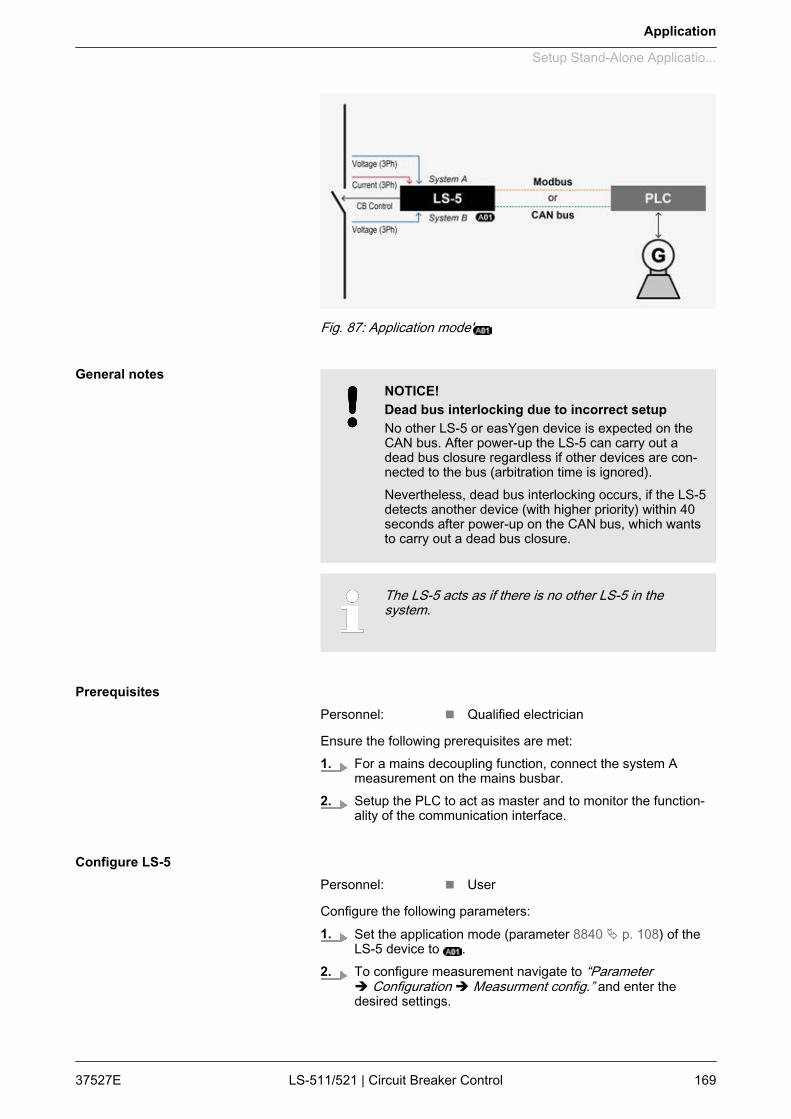
Fig. 87: Application mode'
NOTICE!Dead bus interlocking due to incorrect setupNo other LS-5 or easYgen device is expected on theCAN bus. After power-up the LS-5 can carry out adead bus closure regardless if other devices are con‐nected to the bus (arbitration time is ignored).Nevertheless, dead bus interlocking occurs, if the LS-5detects another device (with higher priority) within 40seconds after power-up on the CAN bus, which wantsto carry out a dead bus closure.
The LS-5 acts as if there is no other LS-5 in thesystem.
Personnel: n Qualified electrician
Ensure the following prerequisites are met:1. For a mains decoupling function, connect the system A
measurement on the mains busbar.2. Setup the PLC to act as master and to monitor the function‐
ality of the communication interface.
Personnel: n User
Configure the following parameters:1. Set the application mode (parameter 8840 Ä p. 108) of the
LS-5 device to .2. To configure measurement navigate to “Parameter
è Configuration è Measurment config.” and enter thedesired settings.
General notes
Prerequisites
Configure LS-5
Application
Setup Stand-Alone Applicatio...
37527E LS-511/521 | Circuit Breaker Control 169

3.When tapping voltages over power transformer,phase angle compensation may be required.
If a phase angle compensation is required, navigate to“Configuration è Application config è Breakers config.è Configure CBA è Synchronization CBAè Phase angle compensation”
NOTICE!Component damageIncorrect settings may cause erratic systembehaviour and damage to the involved compo‐nents .– Set the values carefully and double check
with a voltmeter at the according breaker.
4. If control to open and close the breaker should be handled bydiscrete inputs, use the default setting according to the wiringdiagram (Ä Chapter 3.3.2 “Wiring Diagram” on page 34).
5. If control to open and close the breaker should be handled bycommunication interface, the register with the remote controlbits is used (LM Command variables 04.44 to 04.59, Bit 1 toBit 16).For more information on how to address the according dataregister refer to Ä Chapter 7 “Interfaces And Protocols”on page 225.
6. To configure the close command, the LogicsManager equa‐tion "Enable close CBA" can be modified.Navigate to “Configuration è Application configè Breakers config. è Configure CBA è Enable close CBA”and enter the desired arguments.
7. To configure the open command, the LogicsManager equa‐tion "Open CBA immed." can be modified.Navigate to “Configuration è Application configè Breakers config. è Configure CBA è Open CBA immed.”and enter the desired arguments.
The open command can only be executedthrough the LogicsManager equation "Open CBAunload", if the PLC can influence the unloadingof the breaker.
8. If manual operation via push buttons acting on DI is required,the two LogicsManager equations "Open CBA in manual"and "Close CBA in manual" can be used.Set the equation "Open CBA in manual" (“Immediateè With unl.” to "Immediate".
Application
Setup Stand-Alone Applicatio...
37527ELS-511/521 | Circuit Breaker Control170
9. The LS-5 can be adjusted for different kinds of breaker clo‐sure.Navigate to “Configuration è Application config.è Configure CBA” to configure specific kinds of breaker clo‐sure.Configure "Dead bus closure CBA" to generally handle anykind of dead busbar closure.
6.3 Setup easYgen & Slave LS-5 Applications (Mode A03 & A04)6.3.1 Introduction
In application modes and the LS-5 runs as a slave unit. Inthese modes the LS-5 is guided by the easYgen and takes overdirectly the close and open commands coming from theeasYgen(s).No external logic is needed to decide, when the breaker is to openor to close. The operating mode MANUAL in the LS-5 is not sup‐ported.Manual control is provided by the easYgen(s). The isolation switchinput of the LS-5 is ignored. The LS-5 sends measuring values andflags to the CAN bus connected easYgen(s), which are needed forthe according application mode.The application mode determines the fixed segment numbers forsystem A and B. The LogicsManager for close and open com‐mands are faded out.
The applications where the LS-5 is configured to and are fixed and can not be varied except for thenumber of generators, feeding on the generator busbar(max. 32). Other tie-breakers are not allowed.
The LS-5 is expecting at least one easYgen device inthe system.
Complex applications may require external close andopen logic (via PLC).
In application mode and the operating modeMANUAL is not supported in the LS-5.
The following chapters provide step by step instructions on how toset up the following predefined applications:
General notes
Predefined applications
Application
Setup easYgen & Slave LS-5 A... > Introduction
37527E LS-511/521 | Circuit Breaker Control 171
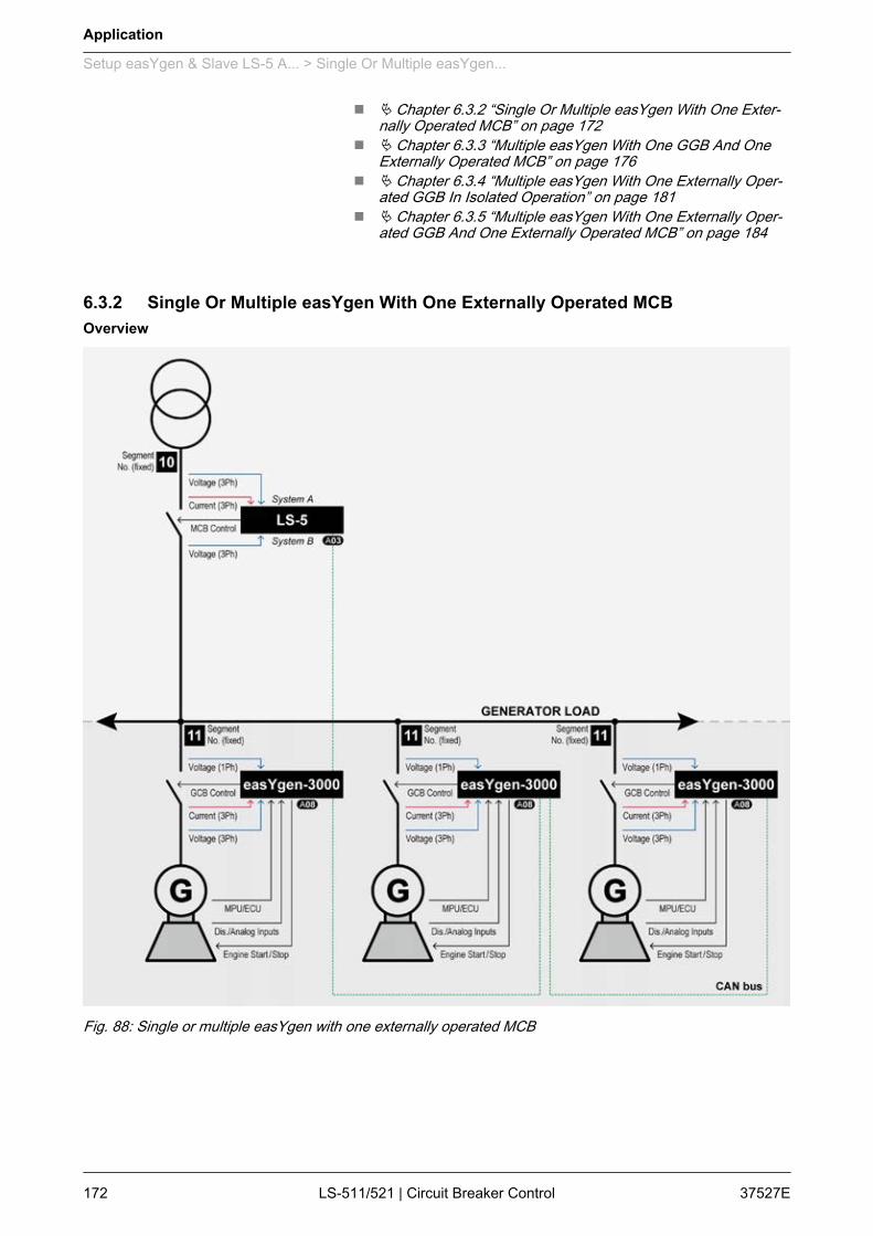
n Ä Chapter 6.3.2 “Single Or Multiple easYgen With One Exter‐nally Operated MCB” on page 172
n Ä Chapter 6.3.3 “Multiple easYgen With One GGB And OneExternally Operated MCB” on page 176
n Ä Chapter 6.3.4 “Multiple easYgen With One Externally Oper‐ated GGB In Isolated Operation” on page 181
n Ä Chapter 6.3.5 “Multiple easYgen With One Externally Oper‐ated GGB And One Externally Operated MCB” on page 184
6.3.2 Single Or Multiple easYgen With One Externally Operated MCB
Fig. 88: Single or multiple easYgen with one externally operated MCB
Overview
Application
Setup easYgen & Slave LS-5 A... > Single Or Multiple easYgen...
37527ELS-511/521 | Circuit Breaker Control172
One or more gensets feed on a load busbar. The easYgen(s) closeand open their own generator breaker. The LS-5 at the interchangepoint closes and opens the MCB. All breakers are connected to thesame segment; the generator busbar is equal to the load busbar.The easYgen(s) are running the same tasks as in the applicationmode GCB/MCB with the differentiation, that instead of a directMCB handling now the LS-5 is taking over that part.The decision when to close or open the MCB is coming from theeasYgen(s) via CAN bus. The manual control on the MCB isrestricted on the easYgen(s). If a run-up synchronization is desired,only the mode "with GCB" is supported.In this setup the mains decoupling is provided by the LS-5.Required application modes:n easYgen-3400/3500: n LS-5:
To provide mains decoupling, acting on the GCB, themains decoupling function of the easYgen must beused.– Refer to the corresponding chapter of the easYgen
manual.
This application setup is predefined and allows for novariations, except the amount of easYgen-3000 drivengenerators (up to 32).– Check whether your application is compatible with
the prerequisites listed below.
Personnel: n Qualified electrician
Ensure the following prerequisites are met:1. The system A voltage and current measurement is con‐
nected to the mains.2. The system B voltage measurement is connected to the
busbar.3. The MCB breaker feedback is connected to the LS-5 only.4. The MCB breaker command(s) are connected to the LS-5
only.5. The LS-5 CAN bus is connected to the CAN bus #3 of the
easYgen(s).
General notes
Prerequisites LS-5
Application
Setup easYgen & Slave LS-5 A... > Single Or Multiple easYgen...
37527E LS-511/521 | Circuit Breaker Control 173
Personnel: n Qualified electrician
Ensure the following prerequisites are met:1. The generator voltage and current measurement is con‐
nected to the generator.2. The busbar voltage measurement is connected to the
busbar.3. The mains voltage measurement is not used.4. The GCB breaker feedback is connected to the according
easYgen.5. The GCB breaker command(s) are connected to the
according easYgen.6. The easYgen CAN bus #3 is connected to the CAN bus of
the LS-5.
Personnel: n User
Configure the following parameters:1. Configure the application mode (parameter 8840 Ä p. 108) of
the LS-5 device to .2. Configure the measurement system A and B.3.
When tapping voltages over power transformer,phase angle compensation may be required.
If a phase angle compensation is required, navigate to“Configuration è Application config è Breakers config.è Configure CBA è Synchronization CBAè Phase angle compensation”
NOTICE!Component damageIncorrect settings may cause erratic systembehaviour and damage to the involved compo‐nents .– Set the values carefully and double check
with a voltmeter at the according breaker.
4. Configure the breaker close and/or open relay(s) accordingto your MCB.
5. Check the synchronization setting, like phase angle, fre‐quency window and voltage.
Prerequisites easYgen
Configure LS-5
Application
Setup easYgen & Slave LS-5 A... > Single Or Multiple easYgen...
37527ELS-511/521 | Circuit Breaker Control174

Personnel: n User
Configure the following parameters:1. Configure the application mode (parameter 3444) of each
easYgen device to .2. Configure the measurement for generator and busbar
according to the easYgen manual.3. The mains measurement is not used in this application mode.
A couple of settings should be configured as follows.n Switch off the following parameters:
Parameter ID
Mains decoupling 3110
Change of frequency 3058
Overfrequency level 1 2850
Underfrequency level 1 2900
Overfrequency level 2 2856
Underfrequency level 2 2906
Overvoltage level 1 2950
Undervoltage level 1 3000
Overvoltage level 2 2956
Undervoltage level 2 3006
Mains voltage increase 8806
4.When tapping voltages over power transformer,phase angle compensation may be required.
If a phase angle compensation is required, navigate to“Parameter è Configuration è Configure Applicationè Configure Breakers è Configure GCBè Phase angle compensation GCB”.
NOTICE!Component damageIncorrect settings may cause erratic systembehaviour and damage to the involved compo‐nents .– Set the values carefully and double check
with a voltmeter at the according breaker.
5. For displaying the mains values coming from LS-5 on themain screen, navigate to parameter "Show mains data"(parameter 4103) and switch to "LS5".
Configure easYgen
Application
Setup easYgen & Slave LS-5 A... > Single Or Multiple easYgen...
37527E LS-511/521 | Circuit Breaker Control 175
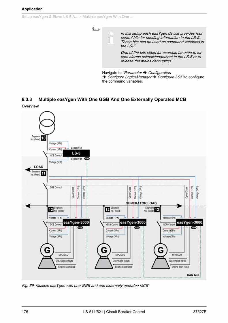
6.In this setup each easYgen device provides fourcontrol bits for sending information to the LS-5.These bits can be used as command variables inthe LS-5.One of the bits could for example be used to ini‐tiate alarms acknowledgement in the LS-5 or torelease the mains decoupling.
Navigate to “Parameter è Configurationè Configure LogicsManager è Configure LS5” to configurethe command variables.
6.3.3 Multiple easYgen With One GGB And One Externally Operated MCB
Fig. 89: Multiple easYgen with one GGB and one externally operated MCB
Overview
Application
Setup easYgen & Slave LS-5 A... > Multiple easYgen With One ...
37527ELS-511/521 | Circuit Breaker Control176
One or more gensets feed on a generator busbar. The easYgen(s)close and open their own generator breaker. The easYgen(s) closeand open the common generator group breaker (GGB). The LS-5at the interchange point closes and opens the MCB.This application includes a generator busbar and a load busbarand one mains income. The easYgen(s) running the same tasks asin the application mode GCB/GGB/MCB with the differentiation,that instead of a direct MCB handling through the easYgen, theLS-5 controls the MCB.The decision when to close or open the MCB is coming from theeasYgen(s) over the CAN bus. The manual control on the MCB isrestricted on the easYgen(s).If a run-up synchronization is desired, the modes "with GCB" and"with GCB/GGB" are supported. In this setup the mains decouplingis provided by the LS-5.Required application modes:n easYgen-3400/3500: n LS-5:
– For information on mains decoupling over GCBrefer to the corresponding chapter of the easYgenmanual.
The mains measurement of the easYgen(s) are usedfor the load busbar measurement.
This application setup is predefined and allows for novariations, except the amount of easYgen-3000 drivengenerators (up to 32).– Check whether your application is compatible with
the prerequisites listed below.
Personnel: n Qualified electrician
Ensure the following prerequisites are met:1. The system A voltage and current measurement is con‐
nected to the mains.2. The system B voltage measurement is connected to the load
busbar.3. The MCB breaker feedback is connected to the LS-5 only.4. The MCB breaker command(s) are connected to the LS-5
only.5. The LS-5 CAN bus is connected to the CAN bus #3 of the
easYgen(s).
General notes
Prerequisites LS-5
Application
Setup easYgen & Slave LS-5 A... > Multiple easYgen With One ...
37527E LS-511/521 | Circuit Breaker Control 177

Personnel: n Qualified electrician
Ensure the following prerequisites are met:1. The generator voltage and current measurement is con‐
nected to the generator.2. The busbar voltage measurement is connected to the gener‐
ator busbar.3. The mains voltage measurement is connected to the load
busbar.4. The GGB breaker feedback is connected to all easYgens.5. The GGB breaker command(s) are connected to all easY‐
gens.6. The GCB breaker feedback is connected to the according
easYgen.7. The GCB breaker command(s) are connected to the
according easYgen.8. The easYgen CAN bus #3 is connected to the CAN bus of
the LS-5.
Personnel: n User
Configure the following parameters:1. Configure the application mode (parameter 8840 Ä p. 108) of
the LS-5 device to .2. Configure the measurement system A and B.3.
When tapping voltages over power transformer,phase angle compensation may be required.
If a phase angle compensation is required, navigate to“Configuration è Application config è Breakers config.è Configure CBA è Synchronization CBAè Phase angle compensation”
NOTICE!Component damageIncorrect settings may cause erratic systembehaviour and damage to the involved compo‐nents .– Set the values carefully and double check
with a voltmeter at the according breaker.
4. Configure the breaker close and/or open relay(s) accordingto your MCB.
5. Check the synchronization settings, like phase angle, fre‐quency window and voltage.
Prerequisites easYgen
Configure LS-5
Application
Setup easYgen & Slave LS-5 A... > Multiple easYgen With One ...
37527ELS-511/521 | Circuit Breaker Control178
Personnel: n User
Configure the following parameters:1. Configure the application mode (parameter 3444) of each
easYgen device to .2. Configure the measurement for generator and busbar
according to the easYgen manual.3. Configure the mains measurement according to the easYgen
manual, but in relation to the load busbar voltage.The mains measurement of the easYgen is only taken forsynchronization GGB, operating range consideration andphase rotation check.All other easYgen mains measurement functions are notused. A couple of settings should be configured as follows.n Switch off the following parameters:
Parameter ID
Mains decoupling 3110
Change of frequency 3058
Overfrequency level 1 2850
Underfrequency level 1 2900
Overfrequency level 2 2856
Underfrequency level 2 2906
Overvoltage level 1 2950
Undervoltage level 1 3000
Overvoltage level 2 2956
Undervoltage level 2 3006
Mains voltage increase 8806
4.When tapping voltages over power transformer,phase angle compensation may be required.
If a phase angle compensation over the GCB is required,navigate to “Parameter è Configurationè Configure Application è Configure Breakersè Configure GCB è Phase angle compensation GCB”.
NOTICE!Component damageIncorrect settings may cause erratic systembehaviour and damage to the involved compo‐nents.– Set the values carefully and double check
with a voltmeter at the according breaker.
Configure easYgen
Application
Setup easYgen & Slave LS-5 A... > Multiple easYgen With One ...
37527E LS-511/521 | Circuit Breaker Control 179

5. If a phase angle compensation over the GGB is required,navigate to “MCB phase angle compensation” in ToolKit.
NOTICE!Component damageIncorrect settings may cause erratic systembehaviour and damage to the involved compo‐nents .– Set the values carefully and double check
with a voltmeter at the according breaker.
6. To display the mains values coming from LS-5 on the mainscreen, navigate to "Show mains data" (parameter 4103) andswitch to "LS5".
7.In this setup each easYgen device provides fourcontrol bits for sending information to the LS-5.These bits can be used as command variables inthe LS-5.One of the bits could for example be used to ini‐tiate alarms acknowledgement in the LS-5.
Navigate to “Parameter è Configurationè Configure LogicsManager è Configure LS5” to configurethe command variables.
Application
Setup easYgen & Slave LS-5 A... > Multiple easYgen With One ...
37527ELS-511/521 | Circuit Breaker Control180
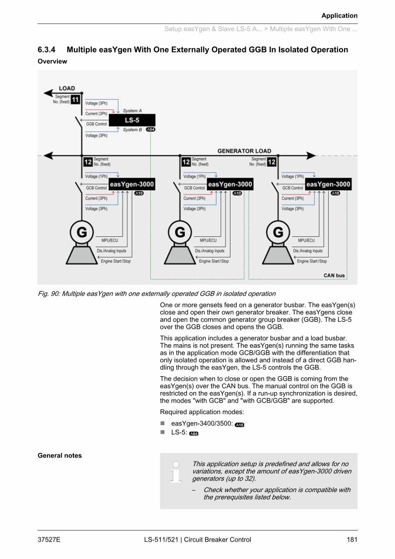
6.3.4 Multiple easYgen With One Externally Operated GGB In Isolated Operation
Fig. 90: Multiple easYgen with one externally operated GGB in isolated operationOne or more gensets feed on a generator busbar. The easYgen(s)close and open their own generator breaker. The easYgens closeand open the common generator group breaker (GGB). The LS-5over the GGB closes and opens the GGB.This application includes a generator busbar and a load busbar.The mains is not present. The easYgen(s) running the same tasksas in the application mode GCB/GGB with the differentiation thatonly isolated operation is allowed and instead of a direct GGB han‐dling through the easYgen, the LS-5 controls the GGB.The decision when to close or open the GGB is coming from theeasYgen(s) over the CAN bus. The manual control on the GGB isrestricted on the easYgen(s). If a run-up synchronization is desired,the modes "with GCB" and "with GCB/GGB" are supported.Required application modes:n easYgen-3400/3500: n LS-5:
This application setup is predefined and allows for novariations, except the amount of easYgen-3000 drivengenerators (up to 32).– Check whether your application is compatible with
the prerequisites listed below.
Overview
General notes
Application
Setup easYgen & Slave LS-5 A... > Multiple easYgen With One ...
37527E LS-511/521 | Circuit Breaker Control 181
Personnel: n Qualified electrician
Ensure the following prerequisites are met:1. The system A voltage measurement is connected to the load
busbar.2. The system B voltage measurement is connected to the gen‐
erator busbar.3. The GGB breaker feedback is connected to the LS-5 only.4. The GGB breaker command(s) are connected to the LS-5
only.5. The LS-5 CAN bus is connected to the CAN bus #3 of the
easYgen(s).
Personnel: n Qualified electrician
Ensure the following prerequisites are met:1. The generator voltage and current measurement is con‐
nected to the generator.2. The busbar voltage measurement is connected to the
busbar.3. The mains voltage measurement is not used.4. The GCB breaker feedback is connected to the according
easYgen.5. The GCB breaker command(s) are connected to the
according easYgen.6. The easYgen CAN bus #3 is connected to the CAN bus of
the LS-5.
Personnel: n User
Configure the following parameters:1. Configure the application mode (parameter 8840 Ä p. 108) of
the LS-5 device to .2. Configure the measurement system A and B.3. Configure the breaker close and/or open relay(s) according
to your GGB.
Personnel: n User
Configure the following parameters:1. Configure the application mode (parameter 3444) of each
easYgen device to .2. Configure the measurement for generator and busbar
according to the easYgen manual.
Prerequisites LS-5
Prerequisites easYgen
Configure LS-5
Configure easYgen
Application
Setup easYgen & Slave LS-5 A... > Multiple easYgen With One ...
37527ELS-511/521 | Circuit Breaker Control182
3. The mains measurement is not used in this application mode.A couple of settings should be configured as follows.n Switch off the following parameters:
Parameter ID
Mains decoupling 3110
Change of frequency 3058
Overfrequency level 1 2850
Underfrequency level 1 2900
Overfrequency level 2 2856
Underfrequency level 2 2906
Overvoltage level 1 2950
Undervoltage level 1 3000
Overvoltage level 2 2956
Undervoltage level 2 3006
Mains voltage increase 8806
4.When tapping voltages over power transformer,phase angle compensation may be required.
If a phase angle compensation over the GCB is required,navigate to “Parameter è Configurationè Configure Application è Configure Breakersè Configure GCB è Phase angle compensation GCB”.
NOTICE!Component damageIncorrect settings may cause erratic systembehaviour and damage to the involved compo‐nents .– Set the values carefully and double check
with a voltmeter at the according breaker.
5.In this setup each easYgen device provides fourcontrol bits for sending information to the LS-5.These bits can be used as command variables inthe LS-5.One of the bits could for example be used to ini‐tiate alarms acknowledgement in the LS-5.
Navigate to “Parameter è Configurationè Configure LogicsManager è Configure LS5” to configurethe command variables.
Application
Setup easYgen & Slave LS-5 A... > Multiple easYgen With One ...
37527E LS-511/521 | Circuit Breaker Control 183
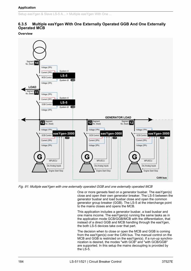
6.3.5 Multiple easYgen With One Externally Operated GGB And One ExternallyOperated MCB
Fig. 91: Multiple easYgen with one externally operated GGB and one externally operated MCBOne or more gensets feed on a generator busbar. The easYgen(s)close and open their own generator breaker. The LS-5 between thegenerator busbar and load busbar close and open the commongenerator group breaker (GGB). The LS-5 at the interchange pointto the mains closes and opens the MCB.This application includes a generator busbar, a load busbar andone mains income. The easYgen(s) running the same tasks as inthe application mode GCB/GGB/MCB with the differentiation, thatinstead of a direct GGB and MCB handling through the easYgen,the both LS-5 devices take over that part.The decision when to close or open the MCB and GGB is comingfrom the easYgen(s) over the CAN bus. The manual control on theMCB and GGB is restricted on the easYgen(s). If a run-up synchro‐nization is desired, the modes "with GCB" and "with GCB/GGB"are supported. In this setup the mains decoupling is provided bythe LS-5.
Overview
Application
Setup easYgen & Slave LS-5 A... > Multiple easYgen With One ...
37527ELS-511/521 | Circuit Breaker Control184

Required application modes:n easYgen-3400/3500: n LS-5: n LS-5:
If mains decoupling over GCB is required, refer to thecorresponding chapter of the easYgen manual.
This application setup is predefined and allows for novariations, except the amount of easYgen-3000 drivengenerators (up to 32).– Check whether your application is compatible with
the prerequisites listed below.
Personnel: n Qualified electrician
Ensure the following prerequisites are met:1. The system A voltage and current measurement is con‐
nected to the mains.2. The system B voltage measurement is connected to the load
busbar.3. The MCB breaker feedback is connected to the LS-5 only.4. The MCB breaker command(s) are connected to the LS-5
only.5. The LS-5 CAN bus is connected to the CAN bus #3 of the
easYgen(s).
Personnel: n Qualified electrician
Ensure the following prerequisites are met:1. The system A voltage measurement is connected to the load
busbar.2. The system B voltage measurement is connected to the gen‐
erator busbar.3. The GGB breaker feedback is connected to the LS-5 only.4. The GGB breaker command(s) are connected to the LS-5
only.5. The LS-5 CAN bus is connected to the CAN bus #3 of the
easYgen(s).
General notes
Prerequisites LS-5 (MCB)
Prerequisites LS-5 (GGB)
Application
Setup easYgen & Slave LS-5 A... > Multiple easYgen With One ...
37527E LS-511/521 | Circuit Breaker Control 185

Personnel: n Qualified electrician
Ensure the following prerequisites are met:1. The generator voltage and current measurement is con‐
nected to the generator.2. The busbar voltage measurement is connected to the gener‐
ator busbar.3. The mains voltage measurement is not used.4. The GCB breaker feedback is connected to the according
easYgen.5. The GCB breaker command(s) are connected to the
according easYgen.6. The easYgen CAN bus #3 is connected to the CAN bus of
the LS-5.
Personnel: n User
Configure the following parameters:1. Configure the application mode (parameter 8840 Ä p. 108) of
the LS-5 device to .2. Configure the measurement system A and B.3.
When tapping voltages over power transformer,phase angle compensation may be required.
If a phase angle compensation over the GCB is required,navigate to “Configuration è Application configè Breakers config. è Configure CBAè Synchronization CBA è Phase angle compensation”
NOTICE!Component damageIncorrect settings may cause erratic systembehaviour and damage to the involved compo‐nents .– Set the values carefully and double check
with a voltmeter at the according breaker.
4. Configure the breaker close and/or open relay(s) accordingto your MCB.
5. Check the synchronization setting, like phase angle, fre‐quency window and voltage.
Prerequisites easYgen
Configure LS-5 (MCB)
Application
Setup easYgen & Slave LS-5 A... > Multiple easYgen With One ...
37527ELS-511/521 | Circuit Breaker Control186
Personnel: n User
Configure the following parameters:1. Configure the application mode (parameter 8840 Ä p. 108) of
the LS-5 device to .2. Configure the measurement system A and B.3.
When tapping voltages over power transformer,phase angle compensation may be required.
If a phase angle compensation over the GCB is required,navigate to “Parameter è Configurationè Configure Application è Configure Breakersè Configure GCB è Phase angle compensation GCB”.
NOTICE!Component damageIncorrect settings may cause erratic systembehaviour and damage to the involved compo‐nents .– Set the values carefully and double check
with a voltmeter at the according breaker.
4. Configure the breaker close and/or open relay(s) accordingto your GGB.
5. Check the synchronization setting, like phase angle, fre‐quency window and voltage.
Personnel: n User
Configure the following parameters:1. Configure the application mode (parameter 3444) of each
easYgen device to .2. Configure the measurement for generator and busbar
according to the easYgen manual.
Configure LS-5 (GGB)
Configure easYgen
Application
Setup easYgen & Slave LS-5 A... > Multiple easYgen With One ...
37527E LS-511/521 | Circuit Breaker Control 187
3. The mains measurement is not used in this application mode.A couple of settings should be configured as follows.n Switch off the following parameters:
Parameter ID
Mains decoupling 3110
Change of frequency 3058
Overfrequency level 1 2850
Underfrequency level 1 2900
Overfrequency level 2 2856
Underfrequency level 2 2906
Overvoltage level 1 2950
Undervoltage level 1 3000
Overvoltage level 2 2956
Undervoltage level 2 3006
Mains voltage increase 8806
4.When tapping voltages over power transformer,phase angle compensation may be required.
If a phase angle compensation over the GCB is required,navigate to “Parameter è Configurationè Configure Application è Configure Breakersè Configure GCB è Phase angle compensation GCB”.
NOTICE!Component damageIncorrect settings may cause erratic systembehaviour and damage to the involved compo‐nents .– Set the values carefully and double check
with a voltmeter at the according breaker.
5. To display the mains values coming from LS-5 on the mainscreen, navigate to “Show mains data” (parameter 4103) andswitch to "LS5".
6.In this setup each easYgen device provides twocontrol bits for sending information to the LS-5.These bits can be used as command variables inthe LS-5.One of the bits could for example be used to ini‐tiate alarms acknowledgement in the LS-5 or torelease the mains decoupling.
Navigate to “Parameter è Configurationè Configure LogicsManager è Configure LS5” to configurethe command variables.
Application
Setup easYgen & Slave LS-5 A... > Multiple easYgen With One ...
37527ELS-511/521 | Circuit Breaker Control188

6.4 Setup easYgen & Independent LS-5 Applications (Mode A02)6.4.1 Introduction
In application mode the LS-5 runs as an independent unit. Thefree LS-5 setup allows up to 32 easYgen-3400/3500 and up to 16LS-5 devices. The easYgen(s) are only operating their GCBs. Theother breakers have to be operated by the LS-5.The closing and opening of the breaker is controlled through theLogicsManager equations "Open CBA unload", "Open CBAimmed." and "Enable close CBA".The close and open commands are configured with LogicsMan‐ager command variables. This can be discrete inputs, remote con‐trol bits or CB control bits coming from the easYgen(s).The operating mode MANUAL in the LS-5 is supported and pro‐vides the operator with the option to manually force a close or openof the breaker. For this purpose the LS-5 provides an operatingmode button and a softkey to close and open the breaker.
The LS-5 is expecting at least one easYgen device inthe system.
Depending on the complexity of the system equallycomplex external program logics may be required.
The LS-5 application mode opens a wide range ofapplications and requires more effort to configure thewhole easYgen – LS-5 system.The sections below explain some of the terms andconcepts required in understanding these more com‐plex applications.
A segment is defined as a section of the bus, feeder or intercon‐nection, which cannot electrically be isolated to a smaller sectionand is connected to a circuit breaker or an isolation switch which isoperated or supervised by an LS-5.A transformer is not considered as a segment or a point of isola‐tion. Each segment, feeder, or interconnection must be assigned anumber that is unique to that segment.
Some applications include existing isolation switches. An isolationswitch is usually taken to interrupt two bars from each other. Thebreaker is usually controlled manually.The LS-5 unit in apllication mode can handle max.1 isolationswitch. Located at the isolation switch, the LS-5 must be informedabout the condition of that switch. The condition determines thesegmenting.
General notes
Segment number
Isolation switch
Application
Setup easYgen & Independent ... > Introduction
37527E LS-511/521 | Circuit Breaker Control 189

The frequency and voltage are solid. A segment number isneeded. The first breaker on the mains side is the MCB.The LS-5 is always connected with measurement system A on themains side. The setting "Mains connection" is always set on"System A". The system A measurement gets the mains segmentnumber.
In this setup there is no direct mains connection neither on systemA or system B. For both sides a segment number is needed.There is no clear rule for where system A or system B needs to beconnected. Likely the location of the CT determines the measure‐ment A B. The setting "Mains connection" is always set to "None".
The frequency and voltage are variable. A segment number is notneeded.
All connected control units must be configured with a uniquedevice number (control number). Hence the units are clear definedin their function and location.The numbers 1 to 32 are reserved for the easYgen(s) (easYgen"Device number"), the numbers 33 to 64 are reserved for the LS-5(parameter 1702 Ä p. 67).
To communicate via the CAN bus it is necessary to configure allconnected controls with a unique CAN bus Node-ID number(parameter 8950 Ä p. 124). Usually the same number like thedevice ID number is taken.
In an emergency application the simultaneous closing of two circuitbreakers is blocked via communications between the LS-5 and theeasYgen. Once an easYgen is enabled for a dead bus connection,it has priority over all LS-5s (any CB controlled by an LS-5 cannotbe closed).If multiple LS-5s are enabled to close a circuit breaker at the sametime the LS-5 with the lowest CAN identification number receivesthe master status (all other LS-5s are inactive).When a closure failure occurs (Ä Chapter 4.3.3 “Breaker”on page 98), this LS-5 is no longer considered for dead bus clo‐sure. The next prioritized LS-5 takes over.
The following chapters provide step by step instructions on how toset up the following predefined applications:n Ä Chapter 6.4.3 “H-Configuration With Two easYgen And Two
Incoming Mains And Tie-breaker” on page 199n Ä Chapter 6.4.4 “Multiple Mains/Generators With Four
easYgen Units, Two Incoming Mains And Different Tie-breakers” on page 210
Mains breaker
Tie-breaker
Generator
Device number (control number)
CAN bus Node-ID number
Priority during breaker closure
Predefined applications
Application
Setup easYgen & Independent ... > Introduction
37527ELS-511/521 | Circuit Breaker Control190

6.4.2 General Functions6.4.2.1 General Preparation
Prepare the easYgen – LS-5 system for configuration as follows:1. Draw a single line diagram that only contains essential equip‐
ment.The schematic should contain all used easYgens, all trans‐formers, all breaker elements (such as circuit breakers andisolation switches), all elements to be controlled, and allLS-5s.
2. Assign numbered addresses for each component of thesystem in accordance with the methods described inÄ Chapter 6.4.1 “Introduction” on page 189.
3. Number all easYgen control units from 1 to 32 (order is user-defined and depends on your application).
4. Number all system LS-5s from 33 to 48 (order is user-definedand depends on your application).
5. Number all CAN Node-IDs (usually the same as the devicenumber).
6. Number all segments according to the definitions in Ä “Seg‐ment number” on page 189.
Unless special numbering conventions arerequired, count up continuously from left to rightor right to left.
7. Draw the measurement system A and B of the single LS-5into the single line diagram according to the definitions inÄ Chapter 6.4.1 “Introduction” on page 189.Keep system A and B on the same side. This simplifies theconfiguration. The location of a CT may force you to ignorethis rule but this can be compensated for in the configuration.
6.4.2.2 Setup Mains Measurement With easYgenIn easYgen application mode mains measurement of theeasYgen is not required. This measurement is provided by theLS-5 unit.
Exception: mains decoupling acting on GCBWhen using the mains decoupling function mainsmeasurement of the easYgen is required.– For information on this setup refer toÄ Chapter 6.4.2.3 “Setup Mains Decoupling WitheasYgen” on page 192.
Personnel: n User
The application uses the easYgen in mode (configured inparameter 8840).
Overview
Prerequisites easYgen
Application
Setup easYgen & Independent ... > General Functions > Setup Mains Measurement Wi...
37527E LS-511/521 | Circuit Breaker Control 191
Personnel: n User
To prevent the easYgen measurement from causing alarms, itmust be configured as follows.
n Switch off the following parameters:
Parameter ID
Mains decoupling 3110
Change of frequency 3058
Overfrequency level 1 2850
Underfrequency level 1 2900
Overfrequency level 2 2856
Underfrequency level 2 2906
Overvoltage level 1 2950
Undervoltage level 1 3000
Overvoltage level 2 2956
Undervoltage level 2 3006
Mains voltage increase 8806
The mains current and power measurement is neverused in the application mode .
6.4.2.3 Setup Mains Decoupling With easYgenTo provide mains decoupling, acting on the GCB, the mains decou‐pling function of the easYgen must be used.
Personnel: n Qualified electrician
Ensure the following prerequisites are met:The mains measurement is connected together with thebusbar measurement on the generator busbar.
For detailed information on the easYgen configuration,refer to the easYgen-3400/3500 manual.
Configure easYgen
Overview
Prerequisites easYgen
Configure easYgen
Application
Setup easYgen & Independent ... > General Functions > Setup Mains Decoupling Wit...
37527ELS-511/521 | Circuit Breaker Control192
6.4.2.4 Setup Mains Decoupling With LS-5In this setup the mains decoupling is provided by the LS-5 for theMCB.
When the mains decoupling over GCB is required,refer to Ä Chapter 6.4.2.3 “Setup Mains DecouplingWith easYgen” on page 192.
The LS-5(s) which are responsible for the mains breakers takeover the mains monitoring and execute the decoupling function.
Personnel: n Qualified electrician
Ensure the following prerequisites are met:1. The mains monitoring is set up with the measurement system
A.2. The measurement system A is connected on the mains side.
Configure the following parameters:1. Navigate to “Configuration è Monitoring config.
è System A” and configure parameter 1771 Ä p. 74 to"Phase-Phase (Ph-Ph)" or "Phase-Neutral (Ph-N)".
2. Navigate to “Operating voltage” and configure the operatingrange for voltage.
– Make sure not configure the range smallerthan the decoupling threshold (see below).
3. Navigate to “Operating frequency” and configure the oper‐ating range for frequency.
– Make sure not configure the range smallerthan the decoupling threshold (see below).
4. Configure the mains settling time (parameter 2801 Ä p. 75).The mains settling time determines for how long the mainsstay continuously stable, before the MCB is closed again.
Multiple LS-5s on different mains incoming pointsshould have the same setting.
Overview
Prerequisites LS-5
Configure LS-5
Application
Setup easYgen & Independent ... > General Functions > Setup Mains Decoupling Wit...
37527E LS-511/521 | Circuit Breaker Control 193
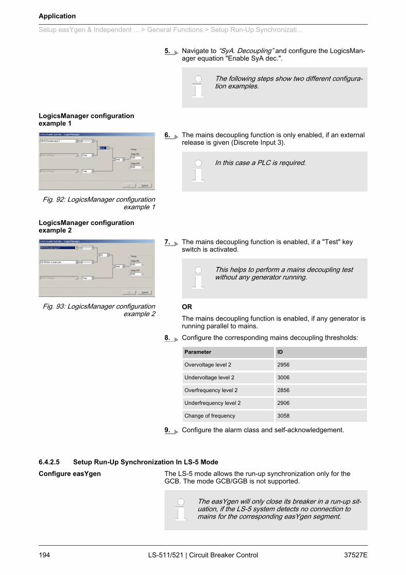
5. Navigate to “SyA. Decoupling” and configure the LogicsMan‐ager equation "Enable SyA dec.".
The following steps show two different configura‐tion examples.
6. The mains decoupling function is only enabled, if an externalrelease is given (Discrete Input 3).
In this case a PLC is required.
7. The mains decoupling function is enabled, if a "Test" keyswitch is activated.
This helps to perform a mains decoupling testwithout any generator running.
ORThe mains decoupling function is enabled, if any generator isrunning parallel to mains.
8. Configure the corresponding mains decoupling thresholds:
Parameter ID
Overvoltage level 2 2956
Undervoltage level 2 3006
Overfrequency level 2 2856
Underfrequency level 2 2906
Change of frequency 3058
9. Configure the alarm class and self-acknowledgement.
6.4.2.5 Setup Run-Up Synchronization In LS-5 ModeThe LS-5 mode allows the run-up synchronization only for theGCB. The mode GCB/GGB is not supported.
The easYgen will only close its breaker in a run-up sit‐uation, if the LS-5 system detects no connection tomains for the corresponding easYgen segment.
LogicsManager configurationexample 1
Fig. 92: LogicsManager configurationexample 1
LogicsManager configurationexample 2
Fig. 93: LogicsManager configurationexample 2
Configure easYgen
Application
Setup easYgen & Independent ... > General Functions > Setup Run-Up Synchronizati...
37527ELS-511/521 | Circuit Breaker Control194
Regarding run-up synchronization there is nothing toconfigure in the LS-5.
6.4.2.6 Setup AMF Start In LS-5 ModeThe AMF start of the easYgen(s) is controlled by segments. Thedesign engineer has to consider, which segments should be moni‐tored and cause an AMF start.For this case the easYgen provides a special setting, where theprocedure runs as follows:1. The easYgen(s) monitors the configured segment(s) on
being not in opertion range.2. If only one segment is recognized as not within operating
range, the generator starts after the emergency run delaytime.
3. After a successful start, all generator breakers are closed.
To avoid the LS-5 of the MCB staying closed duringemergency run, the according LS-5 has to open itsown breaker.The example below shows a solution where the"System A Not-OK" flag opens the MCB automaticallyafter the emergency delay time.The system A condition flags are generated out of theoperating ranges for system A.– For additional information refer toÄ Chapter 6.4.2.3 “Setup Mains Decoupling WitheasYgen” on page 192.
The easYgen feeds its own segment during emergency run. TheAMF mode is only stopped, if all monitored segments are OK forthe mains settling time and have reestablished the connection tomains.
The operating ranges and the main settling time areconfigured in the LS-5s.
Personnel: n User
Configure the following parameters for the LS-5 unit over the MCB:1. Navigate to “Configuration è Monitoring config.
è System A”.2. Navigate to “Operating voltage” and configure the operating
range for voltage.
Configure LS-5
Overview
Configure LS-5
Application
Setup easYgen & Independent ... > General Functions > Setup AMF Start In LS-5 Mo...
37527E LS-511/521 | Circuit Breaker Control 195

3. Navigate to “Operating frequency” and configure the oper‐ating range for frequency.
4. Navigate to “Configuration è Application config.è Breakers config. è Configure CBA” and configure "OpenCBA immed." as shown in the screenshot.LS-5 over the MCB:n The LS-5 issues an MCB open command, if the mains
(system A) is not in operating range.n To avoid flicker trouble, the open command is delayed.
There may other solutions exist to open theMCB. The LogicsManager system provides awide range of flags and conditions to take from.So another example could be to incorporate aflag coming from easYgen, which signals suc‐cesssful start.
Personnel: n User
Configure the following parameters:1. Configure the application mode of the easYgen device to .2. Navigate to “Parameter è Configuration
è Configure emergency run” and configure "Mains fail delaytime", "LM inhibit emerg.run", "Break emerg. in crital mode"according to your application.
3. Configure the emergency run segments in each easYgen.They can differ between easYgens or easYgen groups.
Fig. 95: Segment configuration in ToolKitð The example shows the segment configuration according
to Ä Chapter 6.4.3 “H-Configuration With Two easYgenAnd Two Incoming Mains And Tie-breaker” on page 199.
Fig. 94: LogicsManager configuration
Configure easYgen(s)
Application
Setup easYgen & Independent ... > General Functions > Setup AMF Start In LS-5 Mo...
37527ELS-511/521 | Circuit Breaker Control196
6.4.2.7 Setup Manual Breaker Control In LS-5 ModeThe LS-5 mode provides manual closing and opening of the circuitbreaker at the particular LS-5.This can be configured via LogicsManager equations. The displayvariant provides additionally soft keys in the display. The soft keystake part of the key lock function for security reasons or unintendedoperations.
The easYgen(s) have no direct influence on themanual control of the LS-5(s).
6.4.2.8 Setup LS-5 Command Bits From easYgen To LS-5The easYgen provides six LS-5 command bits in this applicationmode. The command bits are transported via CAN interface toeach LS-5.The design engineer can decide, if he wants to take the OR'edLS-5 command flags coming from all easYgens or if he wants totake the individual command flag coming from a special easYgen.In the example an 'acknowledge' alarm command could be a gen‐eral flag which would be taken from the OR'ed source.A special close command in the example could come from a spe‐cific easYgen and must be therefore not taken from the OR'ed list.
Fig. 96: easYgen information transport to LS-5
Overview
Overview
Application
Setup easYgen & Independent ... > General Functions > Setup LS-5 Command Bits Fr...
37527E LS-511/521 | Circuit Breaker Control 197
6.4.2.9 Setup LS-5 Flags From LS-5 To LS-5 And easYgenThe LS-5 flags generated in the LS-5 device with LogicsManagerequations can be used from connected LS-5 and easYgen devices.Each LS-5 sends five flags over the CAN interface.The system allows to inform or to command something to otherunits. In the example the 'acknowledge' command can be sent toall other units to reset alarms. All bits are individual.
Fig. 97: LS-5 information transport to LS-5 and easYgen
Overview
Application
Setup easYgen & Independent ... > General Functions > Setup LS-5 Flags From LS-5...
37527ELS-511/521 | Circuit Breaker Control198
6.4.3 H-Configuration With Two easYgen And Two Incoming Mains And Tie-breaker
Fig. 98: H-Configuration with two easYgen and two incoming mains and tie-breakerOne or more genset(s) feed on a generator/load busbar (Fig. 98/Segment No. 2). One or more genset(s) feed on a generator/loadbusbar (Fig. 98/Segment No. 3). A tie-breaker is located betweenthe both generator/load busbars. Each generator/load busbar hasits own incoming mains breaker (Fig. 98/ Segment No. 1/4).The easYgen(s) are started by a remote start signal or by AMFmode and operating their GCBs. The other breakers, handled fromthe LS-5, receive their breaker open and close commands throughorders coming from an external logic. The external logic could be adiscrete input, a remote control bit, a monitor function, an easYgencommand, etc..In this example the decision when to close or open the breaker ismanaged by a PLC sending its orders over the CANopen protocol.Serial Modbus can also be used to send orders or read informationfrom all members.
Overview
Application
Setup easYgen & Independent ... > H-Configuration With Two e...
37527E LS-511/521 | Circuit Breaker Control 199
For additional information refer to Ä Chapter 7 “Inter‐faces And Protocols” on page 225.
Amongst others, the breaker feedbacks of the single LS-5 are sentvia the CAN interface and inform all other connected devices in thesystem, whether they are interconnected or not. This determinesthe argument of the regulation for the easYgen (i.e. power control,frequency control, load sharing).Required application modes:n easYgen-3400/3500: n LS-5:
Please note that the measured power of all LS-5s inthe same segment are accumulated if there a severalmains interchange points. The import/export control isbased on this accumulated power. It is not posssible toindividually control the power at the single mains inter‐change points in the same segment.
All units must be configured according to the require‐ments listed in Ä Chapter 6.4.1 “Introduction”on page 189.The following example does not contain any isolationswitches, which could divide the segments.
Prepare the easYgen – LS-5 system for configuration as follows:1. Draw a single line diagram that only contains essential equip‐
ment.In this case the schematic should contain two incomingmains with MCBs, two or more generators per generator seg‐ment, and all breakers (tie-breaker, GCB, MCB).
2. Number all easYgen control units from 1 to 32.3. Number all system LS-5s from 33 to 48.4. Number all CAN Node-IDs (usually the same as the device
number).5. Number all segments according to the definitions in Ä “Seg‐
ment number” on page 189.
Unless special numbering conventions arerequired, count up continuously from left to rightor right to left.
General notes
Single line diagram
Application
Setup easYgen & Independent ... > H-Configuration With Two e...
37527ELS-511/521 | Circuit Breaker Control200
6. Draw the measurement system A and B of the single LS-5into the single line diagram according to the definitions inÄ Chapter 6.4.1 “Introduction” on page 189.Keep system A and B on the same side. This simplifies theconfiguration. The location of a CT may force you to ignorethis rule but this can be compensated for in the configuration.
Personnel: n Qualified electrician
Ensure the following prerequisites are met:1. The system A voltage and current measurement is con‐
nected to the mains.2. The system B voltage measurement is connected to the gen‐
erator/load busbar.3. The MCB breaker feedback is connected to the LS-5 only.4. The MCB breaker commands are connected to the LS-5
only.5. The LS-5 CAN bus is connected to the CAN bus #3 of the
easYgen(s).
Personnel: n Qualified electrician
Ensure the following prerequisites are met:1. The system A voltage and current measurement is con‐
nected to the generator/load busbar segment (Fig. 98/Seg‐ment No. 2).
2. The system B voltage measurement is connected to the gen‐erator/load busbar segment (Fig. 98/Segment No. 3).
3. The tie-breaker feedback is connected to the LS-5 only.4. The tie-breaker commands are connected to the LS-5 only.5. The LS-5 CAN bus is connected to the CAN bus #3 of the
easYgen(s).
Personnel: n Qualified electrician
Ensure the following prerequisites are met:1. The generator voltage and current measurement is con‐
nected to the generator.2. The busbar voltage measurement is connected to the gener‐
ator/load busbar.3. The mains voltage measurement is not used.4. The GCB breaker feedback is connected to the according
easYgen.5. The GCB breaker commands are connected to the according
easYgen.6. The easYgen CAN bus #3 is connected to the CAN bus of
the LS-5.
Prerequisites LS-5 (incomingmains)
Prerequisites LS-5 (tie-breaker)
Prerequisites easYgen(s)
Application
Setup easYgen & Independent ... > H-Configuration With Two e...
37527E LS-511/521 | Circuit Breaker Control 201
Personnel: n User
Configure the following parameters:1. Configure the application mode (parameter 8840 Ä p. 108) of
the LS-5 device to .2. Enter the device ID 33 for the LS-5, incoming mains on the
left side and ID 35 for the LS-5, incoming mains on the right.3. Enter the Node-IDs (usually the same like device ID).4. For the following two steps navigate to “Configuration
è Application config è Segment config.” on each respectiveLS-5.
5. Configure the following parameters for the LS-5 ID 33,incoming mains on the left side:
Parameter ID Value
Segment No. Sy.A 8810 Ä p. 116 1
Segment No. Sy.B 8811 Ä p. 116 2
Segment No. isol. Switch 8812 Ä p. 116 N/A
Mains pow. Measurement 8813 Ä p. 116 Valid
Mains connection 8814 Ä p. 116 System A
Isol. Switch Para 8815 Ä p. 116 None
Variable system 8816 Ä p. 117 System B
6. Configure the following parameters for the LS-5 ID 35,incoming mains on the right side:
Parameter ID Value
Segment No. Sy.A 8810 Ä p. 116 4
Segment No. Sy.B 8811 Ä p. 116 3
Segment No. isol. Switch 8812 Ä p. 116 N/A
Mains pow. Measurement 8813 Ä p. 116 Valid
Mains connection 8814 Ä p. 116 System A
Isol. Switch Para 8815 Ä p. 116 None
Variable system 8816 Ä p. 117 System B
Configure LS-5 (incoming mains)
Application
Setup easYgen & Independent ... > H-Configuration With Two e...
37527ELS-511/521 | Circuit Breaker Control202
7.When tapping voltages over power transformer,phase angle compensation may be required.
If a phase angle compensation over the MCB is required,navigate to “Configuration è Application configè Breakers config. è Configure CBAè Synchronization CBA è Phase angle compensation”
NOTICE!Component damageIncorrect settings may cause erratic systembehaviour and damage to the involved compo‐nents .– Set the values carefully and double check
with a voltmeter at the according breaker.
8. Configure the breaker close and/or open relay(s) accordingto your MCB.
9. Check the synchronization settings, like phase angle, fre‐quency window and voltage.
10. Navigate to “Configuration è Application configè Breakers config. è Configure CBAè Dead bus closure CBA” and set the following parameters:
Parameter ID Value
Dead bus closure CBA 8801 Ä p. 114 On
Connect A dead to B dead 8802 Ä p. 114 Off
Connect A dead to B alive 8803 Ä p. 114 Off
Connect A alive to B dead 8804 Ä p. 114 Off
Dead bus closure delay time 8805 Ä p. 115 As required
Dead bus detection max. volt 5820 Ä p. 115 As required
11. Navigate to “Configuration è Application configè Breakers config. è Configure CBAè Connect synchronous mains” and set the following param‐eters:
Parameter ID Value
Connect synchronous mains 8820 Ä p. 109 Yes
Max. phase angle 8821 Ä p. 110 20°
Delay time phi max. 8822 Ä p. 110 1 s
12. To configure the LogicsManager in regards to close andopen commands for the MCB navigate to “Configurationè Application config è Breakers config. è Configure CBA”.
Application
Setup easYgen & Independent ... > H-Configuration With Two e...
37527E LS-511/521 | Circuit Breaker Control 203
13. Select “Open CBA unload è LogicsManager” (parameter12943 Ä p. 110) and configure the equation as follows:n The LM equation opens the MCB with unloading, if the
remote control bit 1 is sent by the PLC.
14. Select “Open CBA immed. è LogicsManager” (parameter12944 Ä p. 111) and configure the equation as follows:n The LM equation opens the MCB immediately, if the
system A voltage / frequency is not within the configuredoperating ranges (refer to Ä Chapter 4.3.1.1 “ System AOperating Voltage / Frequency” on page 75) OR theremote control bit 2 sent by the PLC.
15. Select “Enable close CBA è LogicsManager” (parameter12945 Ä p. 111) and configure the equation as follows:n The LM equation gives the release for close MCB, if the
remote control bit 3 is sent by the PLC AND the CBA hasno closure failure AND the system A measurementdetects no phase rotation error.
The same remote control bits can be used in theupper example, because each LS-5 receives itsown control bits. The different device and Node-ID separates the control bits from each other.
Personnel: n User
Configure the following parameters:1. Configure the application mode (parameter 8840 Ä p. 108) of
the LS-5 device to .2. Enter the device ID 34 for the LS-5.3. Enter the Node-IDs (usually the same like device ID).
Fig. 99: LogicsManager configuration'Open CBA unload'
Fig. 100: LogicsManager configura‐tion 'Open CBA immed.'
Fig. 101: LogicsManager configura‐tion 'Enable close CBA.'
Configure LS-5 (tie-breaker)
Application
Setup easYgen & Independent ... > H-Configuration With Two e...
37527ELS-511/521 | Circuit Breaker Control204

4. Navigate to “Configuration è Application configè Segment config.” and configure the following parameters:
Parameter ID Value
Segment No. Sy.A 8810 Ä p. 116 2
Segment No. Sy.B 8811 Ä p. 116 3
Segment No. isol. Switch 8812 Ä p. 116 N/A
Mains pow. Measurement
(Actually system A measurement)
8813 Ä p. 116 Invalid
Mains connection 8814 Ä p. 116 None
Isol. Switch Para 8815 Ä p. 116 None
Variable system 8816 Ä p. 117 System B
5. Configure the measurement system A and B.6.
When tapping voltages over power transformer,phase angle compensation may be required.
If a phase angle compensation over the tie-breaker isrequired, navigate to “Configuration è Application configè Breakers config. è Configure CBAè Synchronization CBA è Phase angle compensation”
NOTICE!Component damageIncorrect settings may cause erratic systembehaviour and damage to the involved compo‐nents .– Set the values carefully and double check
with a voltmeter at the according breaker.
7. Configure the breaker close and/or open relay(s) accordingto your tie-breaker.
8. Check the synchronization settings, like phase angle, fre‐quency window and voltage.
9. Navigate to “Configuration è Application configè Breakers config. è Configure CBAè Dead bus closure CBA” and set the following parameters:
Parameter ID Value
Dead bus closure CBA 8801 Ä p. 114 On
Connect A dead to B dead 8802 Ä p. 114 On
Connect A dead to B alive 8803 Ä p. 114 On
Connect A alive to B dead 8804 Ä p. 114 On
Dead bus closure delay time 8805 Ä p. 115 As required
Dead bus detection max. volt 5820 Ä p. 115 As required
Application
Setup easYgen & Independent ... > H-Configuration With Two e...
37527E LS-511/521 | Circuit Breaker Control 205
10. Navigate to “Configuration è Application configè Breakers config. è Configure CBAè Connect synchronous mains” and set the following param‐eters:
Parameter ID Value
Connect synchronous mains 8820 Ä p. 109 Yes
Max. phase angle 8821 Ä p. 110 20°
Delay time phi max. 8822 Ä p. 110 1 s
11. To configure the LogicsManager in regards to close andopen commands for the tie-breaker navigate to“Configuration è Application config è Breakers config.è Configure CBA”.
12. Select “Open CBA unload è LogicsManager” (parameter12943 Ä p. 110) and configure the equation as follows:n The LM equation opens the tie breaker with unloading, if
the remote control bit 1 is sent by the PLC.
The unloading of the tie-breaker is only exe‐cuted, if one side contains a variable system.Otherwise the open command is given withoutunloading.
13. Select “Open CBA immed. è LogicsManager” (parameter12944 Ä p. 111) and configure the equation as follows:n The LM equation opens the tie-breaker immediately, if
the remote control bit 2 sent by the PLC.
14. Select “Enable close CBA è LogicsManager” (parameter12945 Ä p. 111) and configure the equation as follows:n The LM equation gives the release for close CBA, if the
remote control bit 3 is sent by the PLC AND the CBA hasno closure failure AND the system A measurementdetects no phase rotation error.
The same remote control bits can be used in theupper example, because each LS-5 receives itsown control bits. The different device and Node-ID separates the control bits from each other.
Fig. 102: LogicsManager configura‐tion 'Open CBA unload'
Fig. 103: LogicsManager configura‐tion 'Open CBA immed.'
Fig. 104: LogicsManager configura‐tion 'Enable close CBA.'
Application
Setup easYgen & Independent ... > H-Configuration With Two e...
37527ELS-511/521 | Circuit Breaker Control206
Personnel: n User
Configure the following parameters:1. Configure the application mode (parameter 3444) of each
easYgen device to .2. Enter the device ID 1 for the easYgen (usually from left to
right).3. Enter the Node-IDs (usually the same like device ID).4. Navigate to “Parameter è Configuration
è Configure Application è Configure Controllerè Configure load share” to enter the basic segment numbersat the easYgen(s).
Position Parameter ID Value
easYgen ID 1
Left side
Segmentnumber
1723 2
easYgen ID 2
Right side
Segmentnumber
1723 3
5. Configure the measurement for generator and busbaraccording to the easYgen manual.
6. The mains measurement is not used in this application mode.A couple of settings should be configured as follows.n Switch off the following parameters:
Parameter ID
Mains decoupling 3110
Change of frequency 3058
Overfrequency level 1 2850
Underfrequency level 1 2900
Overfrequency level 2 2856
Underfrequency level 2 2906
Overvoltage level 1 2950
Undervoltage level 1 3000
Overvoltage level 2 2956
Undervoltage level 2 3006
Mains voltage increase 8806
Configure easYgen(s)
Application
Setup easYgen & Independent ... > H-Configuration With Two e...
37527E LS-511/521 | Circuit Breaker Control 207

7.When tapping voltages over power transformer,phase angle compensation may be required.
If a phase angle compensation over the GCB is required,navigate to “Configuration è Application configè Breakers config. è Configure GCBè Synchronization GCBè Phase angle compensation GCB”
NOTICE!Component damageIncorrect settings may cause erratic systembehaviour and damage to the involved compo‐nents .– Set the values carefully and double check
with a voltmeter at the according breaker.
8. To display the mains values coming from LS-5 on the mainscreen, navigate to “Parameter è Configurationè Configure measurement” and set “Show mains data”(parameter 4103) to "LS5".
Application
Setup easYgen & Independent ... > H-Configuration With Two e...
37527ELS-511/521 | Circuit Breaker Control208
9.For the AMF mode the emergency run segmentshave to be configured (Ä Chapter 6.4.2.6 “SetupAMF Start In LS-5 Mode” on page 195).
Navigate to “Parameter è Configurationè Configure application è Configure emergency run”.In this application two setups are possible:
Example setup 1
Each generator group monitors its own generator/load busbar and mainsincome:
n The easYgens in the left group are configured to "segment 1" and"segment 2".The easYgens on the left side start, if one of these 2 segments is run‐ning outside its operating ranges.On the other side the AMF mode stops, if both segments are back inoperating range and the incoming mains are closed.
n The easYgens in the right group are configured to "segment 3" and"segment 4".The easYgens on the right side start, if one of these 2 segments isrunning outside its operating ranges.On the other side the AMF mode stops, if both segments are back inoperating range and the incoming mains are closed.
Example setup 2
All generators monitor both generator/load busbars and mains incomes.
n All easYgens are configured to "segment 1"; "segment 2"; "segment3" and "segment 4".All easYgen(s) start, if one of these 4 segments is running outside itsoperating ranges.On the other side the AMF mode stops, if all segments are back inoperating range and at least one incoming mains in the own segmentis closed.
10.In this setup each easYgen device provides sixcontrol bits for sending information to the LS-5.These bits can be used as command variables inthe LS-5 to iniate i.e. an alarm acknowledgementor to release the mains decoupling.
To configure these control bits navigate to “Parameterè Configuration è Configure LogicsManagerè Configure LS5”.
Application
Setup easYgen & Independent ... > H-Configuration With Two e...
37527E LS-511/521 | Circuit Breaker Control 209

6.4.4 Multiple Mains/Generators With Four easYgen Units, Two Incoming MainsAnd Different Tie-breakers
Fig. 105: Multiple Mains/Generators with four easYgen units, two incoming mains and different tie-breakersOne or more genset(s) feed on a generator/load busbar (Fig. 105/Segment No. 4). One or more genset(s) feed on a generator/loadbusbar (Fig. 105/Segment No. 5).A tie-breaker is located between the both generator/load busbars.Each generator/load busbar has its own generator group breaker(Fig. 105/Segment No. 2/3 respectively Segment No. 6/7). Theapplication contains two mains interchange points with mainsbreakers (Fig. 105/Segment No. 1/2 respectively Segment No.7/8).Another tie-breaker can connect directly the both plant/load bus‐bars (Fig. 105/Segment No. 2/7). The application example containsa middle voltage level for the plant/load busbar and a low voltagelevel for the generator/load busbar. Therefore step up transformersare installed. Each step up transformer provides a manually oper‐ated isolation switch.Each LS-5 controls its own breaker. The LS-5s at the GGB areadditionally informed about the condition of the close-by isolationswitch.
Overview
Application
Setup easYgen & Independent ... > Multiple Mains/Generators ...
37527ELS-511/521 | Circuit Breaker Control210
The easYgen(s) are started by a remote start signal or by AMFmode and operating their GCBs. The other breakers, handled byLS-5, receive their breaker open and close commands throughorders coming from an external logic. The external logic could be adiscrete input, a remote control bit, a monitor function, etc..In this example the decision when to close or open the breaker ismanaged by a PLC sending its orders over the CANopen protocol.Serial Modbus can also be used to send orders or read informationfrom all members.
For additional information refer to Ä Chapter 7 “Inter‐faces And Protocols” on page 225.
Amongst others the breaker feedbacks of the single LS-5 are sentvia CAN interface and inform all other connected devices in thesystem, whether they are interconnected or not. This determinesthe argument of the regulation for the easYgen (i.e. power control,frequency control, load sharing).Required application modes:n easYgen-3400/3500: n LS-5:
All units must be configured according to the require‐ments listed in Ä Chapter 6.4.1 “Introduction”on page 189.In the following example the isolation switch conditionrepresents an important part of the segmenting.
Prepare the easYgen – LS-5 system for configuration as follows:1. Draw a single line diagram that only contains essential equip‐
ment.In this case the schematic should contain two incomingmains with MCBs, two or more generators per generator/loadbusbar segment and all breakers (tie-breaker, GGB)
2. Number all easYgen control units from 1 to 32.3. Number all system LS-5s from 33 to 48.4. Number all CAN Node-IDs (usually the same as the device
number).5. Number all segments according to the definitions in Ä “Seg‐
ment number” on page 189.
Unless special numbering conventions arerequired, count up continuously from left to rightor right to left.
General notes
Single line diagram
Application
Setup easYgen & Independent ... > Multiple Mains/Generators ...
37527E LS-511/521 | Circuit Breaker Control 211

6. Draw the measurement system A and B of the single LS-5into the single line diagram according to the definitions inÄ Chapter 6.4.1 “Introduction” on page 189.Keep system A and B on the same side. This simplifies theconfiguration. The location of a CT may force you to ignorethis rule but this can be compensated for in the configuration.
Personnel: n Qualified electrician
Ensure the following prerequisites are met:1. The system A voltage and current measurement is con‐
nected to the mains segment no. 1/8.2. The system B voltage measurement is connected to the
plant/load busbar segment no. 2/7.3. The MCB breaker feedback is connected to the LS-5 only.4. The MCB breaker commands are connected to the LS-5
only.5. The LS-5 CAN bus is connected to the CAN bus #3 of the
easYgen(s).
Personnel: n Qualified electrician
Ensure the following prerequisites are met:1. The system A voltage and current measurement is con‐
nected to the plant/load busbar segment no. 2/7.2. The system B voltage measurement is connected to the gen‐
erator/load busbar segment no. 3/6.3. The GGB feedback is connected to the LS-5 only.4. The GGB command(s) are connected to the LS-5 only.5. The isolation switch feedback, located between generator/
load busbar and transformer( segment no.3/4 respectivelysegment no. 5/6), is connected to the LS-5 only.
6. The LS-5 CAN bus is connected to the CAN bus #3 of theeasYgen(s).
Personnel: n Qualified electrician
Ensure the following prerequisites are met:1. The system A voltage and current measurement is con‐
nected to the segment no. 4.2. The system B voltage measurement is connected to the seg‐
ment no. 5.3. The tie-breaker feedback is connected to the LS-5 only.4. The tie-breaker command(s) are connected to the LS-5 only.5. The LS-5 CAN bus is connected to the CAN bus #3 of the
easYgen(s).
Prerequisites LS-5 (incomingmains)
Prerequisites LS-5 (GGBs)
Prerequisites LS-5 (tie-breaker gen‐erator/load busbar)
Application
Setup easYgen & Independent ... > Multiple Mains/Generators ...
37527ELS-511/521 | Circuit Breaker Control212
Personnel: n Qualified electrician
Ensure the following prerequisites are met:1. The system A voltage and current measurement is con‐
nected to the segment no. 2.2. The system B voltage measurement is connected to the seg‐
ment no. 7.3. The tie-breaker feedback is connected to the LS-5 only.4. The tie-breaker command(s) are connected to the LS-5 only.5. The LS-5 CAN bus is connected to the CAN bus #3 of the
easYgen(s).
Personnel: n Qualified electrician
Ensure the following prerequisites are met:1. The generator voltage and current measurement is con‐
nected to the generator.2. The busbar voltage measurement is connected to the gener‐
ator/load busbar.3. The mains voltage measurement is not used.4. The GCB breaker feedback is connected to the according
easYgen.5. The GCB breaker command(s) are connected to the
according easYgen.6. The easYgen CAN bus #3 is connected to the CAN bus of
the LS-5.
Personnel: n User
Configure the following parameters:1. Configure the application mode (parameter 8840 Ä p. 108) of
the LS-5 device to .2. Enter the device ID 33 for the LS-5, incoming mains on the
left side and ID 37 for the LS-5, incoming mains on the right.3. Enter the Node-IDs (usually the same like device ID).4. For the following two steps navigate to “Configuration
è Application config è Segment config.” on each respectiveLS-5.
Prerequisites LS-5 (tie-breakerplant/load busbar)
Prerequisites easYgen(s)
Configure LS-5 (incoming mains)
Application
Setup easYgen & Independent ... > Multiple Mains/Generators ...
37527E LS-511/521 | Circuit Breaker Control 213

5. Configure the following parameters for the LS-5 ID 33,incoming mains on the left side:
Parameter ID Value
Segment No. Sy.A 8810 Ä p. 116 1
Segment No. Sy.B 8811 Ä p. 116 2
Segment No. isol. Switch 8812 Ä p. 116 N/A
Mains pow. Measurement 8813 Ä p. 116 Valid
Mains connection 8814 Ä p. 116 System A
Isol. Switch Para 8815 Ä p. 116 None
Variable system 8816 Ä p. 117 System B
6. Configure the following parameters for the LS-5 ID 37,incoming mains on the right side:
Parameter ID Value
Segment No. Sy.A 8810 Ä p. 116 8
Segment No. Sy.B 8811 Ä p. 116 7
Segment No. isol. Switch 8812 Ä p. 116 N/A
Mains pow. Measurement 8813 Ä p. 116 Valid
Mains connection 8814 Ä p. 116 System A
Isol. Switch Para 8815 Ä p. 116 None
Variable system 8816 Ä p. 117 System B
7. Configure the measurement system A and B.8. Configure the breaker close and/or open relay(s) according
to your MCB.9. Check the synchronization settings, like phase angle, fre‐
quency window and voltage.10. Navigate to “Configuration è Application config
è Breakers config. è Configure CBAè Dead bus closure CBA” and set the following parameters:
Parameter ID Value
Dead bus closure CBA 8801 Ä p. 114 On
Connect A dead to B dead 8802 Ä p. 114 Off
Connect A dead to B alive 8803 Ä p. 114 Off
Connect A alive to B dead 8804 Ä p. 114 On
Dead bus closure delay time 8805 Ä p. 115 As required
Dead bus detection max. volt 5820 Ä p. 115 As required
Application
Setup easYgen & Independent ... > Multiple Mains/Generators ...
37527ELS-511/521 | Circuit Breaker Control214
11. Navigate to “Configuration è Application configè Breakers config. è Configure CBAè Connect synchronous mains” and set the following param‐eters:
Parameter ID Value
Connect synchronous mains 8820 Ä p. 109 Yes
Max. phase angle 8821 Ä p. 110 20°
Delay time phi max. 8822 Ä p. 110 1 s
12. To configure the LogicsManager in regards to close andopen commands for the MCB navigate to “Configurationè Application config è Breakers config. è Configure CBA”.
13. Select “Open CBA unload è LogicsManager” (parameter12943 Ä p. 110) and configure the equation as follows:n The LM equation opens the MCB with unloading, if the
remote control bit 1 is sent by the PLC.
14. Select “Open CBA immed. è LogicsManager” (parameter12944 Ä p. 111) and configure the equation as follows:n The LM equation opens the MCB immediately, if the
system A voltage / frequency is not within the configuredoperating ranges (refer to Ä Chapter 4.3.1.1 “ System AOperating Voltage / Frequency” on page 75) OR theremote control bit 2 sent by the PLC.
15. Select “Enable close CBA è LogicsManager” (parameter12945 Ä p. 111) and configure the equation as follows:n The LM equation gives the release for close MCB, if the
remote control bit 3 is sent by the PLC AND the CBA hasno closure failure AND the system A measurementdetects no phase rotation error.
The same remote control bits can be used in theupper example, because each LS-5 receives itsown control bits. The different device and Node-ID separates the control bits from each other.
Personnel: n User
Configure the following parameters:1. Configure the application mode (parameter 8840 Ä p. 108) of
the LS-5 device to .2. Enter the device ID 34 for the LS-5, set up as GGB on the left
and ID 36 for the LS-5, set up as GGB on the right.
Fig. 106: LogicsManager configura‐tion 'Open CBA unload'
Fig. 107: LogicsManager configura‐tion 'Open CBA immed.'
Fig. 108: LogicsManager configura‐tion 'Enable close CBA.'
Configure LS-5 (GGBs)
Application
Setup easYgen & Independent ... > Multiple Mains/Generators ...
37527E LS-511/521 | Circuit Breaker Control 215

3. Enter the Node-IDs (usually the same like device ID).4. For the following two steps navigate to “Configuration
è Application config è Segment config.” on each respectiveLS-5.
5. Configure the following parameters for the LS-5 ID 34, set upas GGB on the left:
Parameter ID Value
Segment No. Sy.A 8810 Ä p. 116 2
Segment No. Sy.B 8811 Ä p. 116 3
Segment No. isol. Switch 8812 Ä p. 116 4
Mains pow. Measurement
(Actually system A measurement)
8813 Ä p. 116 Invalid
Mains connection 8814 Ä p. 116 None
Isol. Switch Para 8815 Ä p. 116 System B
Variable system 8816 Ä p. 117 System B
6. Configure the following parameters for the LS-5 ID 36, set upas GGB on the right:
Parameter ID Value
Segment No. Sy.A 8810 Ä p. 116 7
Segment No. Sy.B 8811 Ä p. 116 6
Segment No. isol. Switch 8812 Ä p. 116 5
Mains pow. Measurement
(Actually system A measurement)
8813 Ä p. 116 Invalid
Mains connection 8814 Ä p. 116 None
Isol. Switch Para 8815 Ä p. 116 System B
Variable system 8816 Ä p. 117 System B
7. Navigate to “Configuration è Application configè Breakers config.” and configure the isolation switch feed‐back "isol.sw open" for a discrete input (discrete input 5 isrecommended).
8. Configure the measurement system A and B.9. Configure the breaker close and/or open relay(s) according
to your GGB.10. Check the synchronization settings, like phase angle, fre‐
quency window and voltage.
Application
Setup easYgen & Independent ... > Multiple Mains/Generators ...
37527ELS-511/521 | Circuit Breaker Control216

11. Navigate to “Configuration è Application configè Breakers config. è Configure CBAè Dead bus closure CBA” and set the following parameters:
Parameter ID Value
Dead bus closure CBA 8801 Ä p. 114 On
Connect A dead to B dead 8802 Ä p. 114 On
Connect A dead to B alive 8803 Ä p. 114 On
Connect A alive to B dead 8804 Ä p. 114 On
Dead bus closure delay time 8805 Ä p. 115 As required
Dead bus detection max. volt 5820 Ä p. 115 As required
12. Navigate to “Configuration è Application configè Breakers config. è Configure CBAè Connect synchronous mains” and set the following param‐eters:
Parameter ID Value
Connect synchronous mains 8820 Ä p. 109 Yes
Max. phase angle 8821 Ä p. 110 20°
Delay time phi max. 8822 Ä p. 110 1 s
13. To configure the LogicsManager in regards to close andopen commands for the GGB navigate to “Configurationè Application config è Breakers config. è Configure CBA”.
14. Select “Open CBA unload è LogicsManager” (parameter12943 Ä p. 110) and configure the equation as follows:n The LM equation opens the GGB with unloading, if the
remote control bit 1 is sent by the PLC.
15. Select “Open CBA immed. è LogicsManager” (parameter12944 Ä p. 111) and configure the equation as follows:n The LM equation opens the GGB immediately, if the
remote control bit 2 sent by the PLC.
Fig. 109: LogicsManager configura‐tion 'Open CBA unload'
Fig. 110: LogicsManager configura‐tion 'Open CBA immed.'
Application
Setup easYgen & Independent ... > Multiple Mains/Generators ...
37527E LS-511/521 | Circuit Breaker Control 217
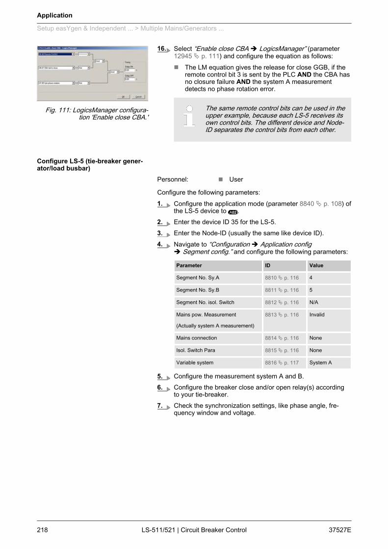
16. Select “Enable close CBA è LogicsManager” (parameter12945 Ä p. 111) and configure the equation as follows:n The LM equation gives the release for close GGB, if the
remote control bit 3 is sent by the PLC AND the CBA hasno closure failure AND the system A measurementdetects no phase rotation error.
The same remote control bits can be used in theupper example, because each LS-5 receives itsown control bits. The different device and Node-ID separates the control bits from each other.
Personnel: n User
Configure the following parameters:1. Configure the application mode (parameter 8840 Ä p. 108) of
the LS-5 device to .2. Enter the device ID 35 for the LS-5.3. Enter the Node-ID (usually the same like device ID).4. Navigate to “Configuration è Application config
è Segment config.” and configure the following parameters:
Parameter ID Value
Segment No. Sy.A 8810 Ä p. 116 4
Segment No. Sy.B 8811 Ä p. 116 5
Segment No. isol. Switch 8812 Ä p. 116 N/A
Mains pow. Measurement
(Actually system A measurement)
8813 Ä p. 116 Invalid
Mains connection 8814 Ä p. 116 None
Isol. Switch Para 8815 Ä p. 116 None
Variable system 8816 Ä p. 117 System A
5. Configure the measurement system A and B.6. Configure the breaker close and/or open relay(s) according
to your tie-breaker.7. Check the synchronization settings, like phase angle, fre‐
quency window and voltage.
Fig. 111: LogicsManager configura‐tion 'Enable close CBA.'
Configure LS-5 (tie-breaker gener‐ator/load busbar)
Application
Setup easYgen & Independent ... > Multiple Mains/Generators ...
37527ELS-511/521 | Circuit Breaker Control218

8. Navigate to “Configuration è Application configè Breakers config. è Configure CBAè Dead bus closure CBA” and set the following parameters:
Parameter ID Value
Dead bus closure CBA 8801 Ä p. 114 On
Connect A dead to B dead 8802 Ä p. 114 On
Connect A dead to B alive 8803 Ä p. 114 On
Connect A alive to B dead 8804 Ä p. 114 On
Dead bus closure delay time 8805 Ä p. 115 As required
Dead bus detection max. volt 5820 Ä p. 115 As required
9. Navigate to “Configuration è Application configè Breakers config. è Configure CBAè Connect synchronous mains” and set the following param‐eters:
Parameter ID Value
Connect synchronous mains 8820 Ä p. 109 Yes
Max. phase angle 8821 Ä p. 110 20°
Delay time phi max. 8822 Ä p. 110 1 s
10. To configure the LogicsManager in regards to close andopen commands for the tie-breaker navigate to“Configuration è Application config è Breakers config.è Configure CBA”.
11. Select “Open CBA unload è LogicsManager” (parameter12943 Ä p. 110) and configure the equation as follows:n The LM equation opens the tie-breaker with unloading, if
the remote control bit 1 is sent by the PLC.
The unloading of the tie-breaker is only exe‐cuted, if one side contains a variable system.Otherwise the open command is given withoutunloading.
12. Select “Open CBA immed. è LogicsManager” (parameter12944 Ä p. 111) and configure the equation as follows:n The LM equation opens the tie-breaker immediately, if
the remote control bit 2 sent by the PLC.
Fig. 112: LogicsManager configura‐tion 'Open CBA unload'
Fig. 113: LogicsManager configura‐tion 'Open CBA immed.'
Application
Setup easYgen & Independent ... > Multiple Mains/Generators ...
37527E LS-511/521 | Circuit Breaker Control 219

13. Select “Enable close CBA è LogicsManager” (parameter12945 Ä p. 111) and configure the equation as follows:n The LM equation gives the release for close CBA, if the
remote control bit 3 is sent by the PLC AND the CBA hasno closure failure AND the system A measurementdetects no phase rotation error.
The same remote control bits can be used in theupper example, because each LS-5 receives itsown control bits. The different device and node-ID separates the control bits from each other.
Personnel: n User
Configure the following parameters:1. Configure the application mode (parameter 8840 Ä p. 108) of
the LS-5 device to .2. Enter the device ID 38 for the LS-5.3. Enter the Node-ID (usually the same like device ID).4. Navigate to “Configuration è Application config
è Segment config.” and configure the following parameters:
Parameter ID Value
Segment No. Sy.A 8810 Ä p. 116 2
Segment No. Sy.B 8811 Ä p. 116 7
Segment No. isol. Switch 8812 Ä p. 116 N/A
Mains pow. Measurement
(Actually system A measurement)
8813 Ä p. 116 Invalid
Mains connection 8814 Ä p. 116 None
Isol. Switch Para 8815 Ä p. 116 None
Variable system 8816 Ä p. 117 System A
5. Configure the measurement system A and B.6. Configure the breaker close and/or open relay(s) according
to your tie-breaker.7. Check the synchronization settings, like phase angle, fre‐
quency window and voltage.
Fig. 114: LogicsManager configura‐tion 'Enable close CBA.'
Configure LS-5 (tie-breaker plant/load busbar)
Application
Setup easYgen & Independent ... > Multiple Mains/Generators ...
37527ELS-511/521 | Circuit Breaker Control220
8. Navigate to “Configuration è Application configè Breakers config. è Configure CBAè Dead bus closure CBA” and set the following parameters:
Parameter ID Value
Dead bus closure CBA 8801 Ä p. 114 On
Connect A dead to B dead 8802 Ä p. 114 On
Connect A dead to B alive 8803 Ä p. 114 On
Connect A alive to B dead 8804 Ä p. 114 On
Dead bus closure delay time 8805 Ä p. 115 As required
Dead bus detection max. volt 5820 Ä p. 115 As required
9. Navigate to “Configuration è Application configè Breakers config. è Configure CBAè Connect synchronous mains” and set the following param‐eters:
Parameter ID Value
Connect synchronous mains 8820 Ä p. 109 Yes
Max. phase angle 8821 Ä p. 110 20°
Delay time phi max. 8822 Ä p. 110 1 s
10. To configure the LogicsManager in regards to close andopen commands for the tie-breaker navigate to“Configuration è Application config è Breakers config.è Configure CBA”.
11. Select “Open CBA unload è LogicsManager” (parameter12943 Ä p. 110) and configure the equation as follows:n The LM equation opens the tie-breaker with unloading, if
the remote control bit 1 is sent by the PLC.
The unloading of the tie-breaker is only exe‐cuted, if one side contains a variable system.Otherwise the open command is given withoutunloading.
12. Select “Open CBA immed. è LogicsManager” (parameter12944 Ä p. 111) and configure the equation as follows:n The LM equation opens the tie-breaker immediately, if
the remote control bit 2 sent by the PLC.
Fig. 115: LogicsManager configura‐tion 'Open CBA unload'
Fig. 116: LogicsManager configura‐tion 'Open CBA immed.'
Application
Setup easYgen & Independent ... > Multiple Mains/Generators ...
37527E LS-511/521 | Circuit Breaker Control 221

13. Select “Enable close CBA è LogicsManager” (parameter12945 Ä p. 111) and configure the equation as follows:n The LM equation gives the release for close CBA, if the
remote control bit 3 is sent by the PLC AND the CBA hasno closure failure AND the system A measurementdetects no phase rotation error.
The same remote control bits can be used in theupper example, because each LS-5 receives itsown control bits. The different device and Node-ID separates the control bits from each other.
Personnel: n User
Configure the following parameters:1. Configure the application mode (parameter 3444) of each
easYgen device to .2. Enter the device ID 1 for the easYgen (usually from left to
right).3. Enter the Node-IDs (usually the same like device ID).4. Navigate to “Parameter è Configuration
è Configure Application è Configure Controllerè Configure load share” to enter the basic segment numbersat the easYgen(s).
Position Parameter ID Value
easYgen ID 1
Left side
Segmentnumber
1723 4
easYgen ID 2
Right side
Segmentnumber
1723 5
5. Configure the measurement for generator and busbaraccording to the easYgen manual.
Fig. 117: LogicsManager configura‐tion 'Enable close CBA.'
Configure easYgen(s)
Application
Setup easYgen & Independent ... > Multiple Mains/Generators ...
37527ELS-511/521 | Circuit Breaker Control222
6. The mains measurement is not used in this application mode.A couple of settings should be configured as follows.n Switch off the following parameters:
Parameter ID
Mains decoupling 3110
Change of frequency 3058
Overfrequency level 1 2850
Underfrequency level 1 2900
Overfrequency level 2 2856
Underfrequency level 2 2906
Overvoltage level 1 2950
Undervoltage level 1 3000
Overvoltage level 2 2956
Undervoltage level 2 3006
Mains voltage increase 8806
7.When tapping voltages over power transformer,phase angle compensation may be required.
If a phase angle compensation over the GCB is required,navigate to “Configuration è Application configè Breakers config. è Configure GCBè Synchronization GCBè Phase angle compensation GCB”
NOTICE!Component damageIncorrect settings may cause erratic systembehaviour and damage to the involved compo‐nents .– Set the values carefully and double check
with a voltmeter at the according breaker.
8. To display the mains values coming from LS-5 on the mainscreen, navigate to “Parameter è Configurationè Configure measurement” and set “Show mains data”(parameter 4103) to "LS5".
Application
Setup easYgen & Independent ... > Multiple Mains/Generators ...
37527E LS-511/521 | Circuit Breaker Control 223
9.For the AMF mode the emergency run segmentshave to be configured (Ä Chapter 6.4.2.6 “SetupAMF Start In LS-5 Mode” on page 195).
Navigate to “Parameter è Configurationè Configure application è Configure emergency run”.In this application two setups are possible:
Example setup 1
Each generator group monitors its own generator/load busbar and mainsincome:
n The easYgens in the left group are configured to "segment 1"; "seg‐ment 2" and "segment 4".The easYgens on the left side start, if at least one of these 3 seg‐ments is running outside its operating ranges.On the other side the AMF mode stops, if all segments are back inoperating range and the incoming mains are closed.
n The easYgens in the right group are configured to "segment 8"; "seg‐ment 7" and "segment 5".The easYgens on the right side start, if at least one of these 3 seg‐ments is running outside its operating ranges.On the other side the AMF mode stops, if all segments are back inoperating range and the incoming mains are closed.
Example setup 2
All generators monitor both generator/load busbars and mains incomes.
n All easYgens are configured to "segment 1"; "segment 2"; "segment4"; "segment 8"; "segment 7" and "segment 5".All easYgen(s) start, if at least one of these 6 segments is runningoutside its operating ranges.On the other side the AMF mode stops, if all segments are back inoperating range and at least one incoming mains in the own segmentis closed.
10.In this setup each easYgen device provides sixcontrol bits for sending information to the LS-5.These bits can be used as command variables inthe LS-5 to iniate i.e. an alarm acknowledgementor to release the mains decoupling.
To configure these control bits navigate to “Parameterè Configuration è Configure LogicsManagerè Configure LS5”.
Application
Setup easYgen & Independent ... > Multiple Mains/Generators ...
37527ELS-511/521 | Circuit Breaker Control224
7 Interfaces And Protocols7.1 Interfaces Overview
Fig. 118: LS-511 interfaces
Fig. 119: LS-521 interfaces
The LS-511/521 (Fig. 118/Fig. 119) provides the following inter‐faces, which are supporting different protocols.
Figure Interface Protocol
A Service Port (USB/RS-232)1 Modbus, ToolKit
B RS-485 Modbus
C CAN bus CANopen
1 Please refer to Ä Chapter 3.3.11 “Service Port”on page 56.
LS-511
LS-521
Interfaces And Protocols
Interfaces Overview
37527E LS-511/521 | Circuit Breaker Control 225

7.2 CAN Interfaces7.2.1 CAN Interface 1 (Guidance level)
CAN interface 1 is a freely configurable CANopen interface with 2RPDOs (receive boxes), 3 TPDOs (send boxes), and 4 additionalServer SDOs.
Fig. 120: CAN interface 1
7.3 Serial Interfaces7.3.1 Service Port (RS-232/USB)
The Woodward specific service port can be used to extend theinterfaces of the controller.In conjunction with the direct configuration cable the service portallows service access for configuring the unit and visualize meas‐ured data. It is possible to connect a modem for remote control andalarm signaling.The extended serial interface provides a Modbus as well as theWoodward ToolKit protocol.
Fig. 121: Service Port
1 The service port can be only used in combinationwith an optional Woodward direct configuration cable(DPC), which inclucdes a converter box to provideeither an USB or a RS-232 interface.– For additional information refer toÄ Chapter 3.3.11 “Service Port” on page 56.
Interfaces And Protocols
Serial Interfaces > Service Port (RS-232/USB)
37527ELS-511/521 | Circuit Breaker Control226

7.3.2 RS-485 InterfaceA freely configurable RS-485 Modbus RTU Slave interface is pro‐vided to add PLC connectivity. It is also possible to configure theunit, visualize measured data and alarm messages, and control theunit remotely.
Fig. 122: RS-485 interface
7.4 CANopen ProtocolCANopen is a communication protocol and device profile specifica‐tion for embedded systems used in automation. The CANopenstandard consists of an addressing scheme, several small commu‐nication protocols and an application layer defined by a device pro‐file. The communication protocols have support for network man‐agement, device monitoring and communication between nodes,including a simple transport layer for message segmentation/desegmentation.
If a data protocol is used, a CAN message looks like this:
Byte 1 Byte 2 Byte 3 Byte 4 Byte 5 Byte 6 Byte 7 Byte 8
MUX Data byte Data byte Data byte Data byte Data byte Data byte Internal
The MUX byte is counted up, the meaning of the data bytechanges according to the value of the MUX byte.In the protocol tables is listed which parameter at which MUX onwhich position is transmitted. The meaning of the parameter canbe taken by means of the number of the parameter description("CANopen Mapping parameter").
MUX Byte 2 Byte 3 Byte 4 Byte 5 Byte 6 Byte 7 Byte 8
1 118 147 Internal
In MUX 1 (byte 1 has got value 1) the value of parameter 118 isincluded in the byte 2 up to byte 5 (mains voltage 1-2). In byte 6up to byte 7 the value of parameter 147 is included (mains fre‐quency). Byte 8 includes internal definitions and can be ignored.
Example
UNSIGNED type data has positive integers as values. The range isbetween 0 and 2n-1. The data is shown by the bit sequence oflength n.n Bit sequence:
b = b0 to bn-1
n Value shown:UNSIGNEDn(b) = bn-1 * 2n-1 + ... + b1 * 21 + b0 * 20
Protocol description
Data format "Unsigned Integer"
Interfaces And Protocols
CANopen Protocol
37527E LS-511/521 | Circuit Breaker Control 227

Please note that the bit sequence starts on the left withthe least significant byte.Example: Value 266 = 10A hex of type UNSIGNED16is transmitted on the bus in two octets, first 0A hex andthen 01 hex.
The following UNSIGNED data types are transmitted as follows:
Octet Number 1. 2. 3. 4. 5. 6. 7. 8.
UNSIGNED8 b7 to b0
UNSIGNED16 b7 to b0 b15 to b8
UNSIGNED24 b7 to b0 b15 to b8 b23 to b16
UNSIGNED32 b7 to b0 b15 to b8 b23 to b16 b31 to b24
UNSIGNED40 b7 to b0 b15 to b8 b23 to b16 b31 to b24 b39 to b32
UNSIGNED48 b7 to b0 b15 to b8 b23 to b16 b31 to b24 b39 to b32 b47 to b40
UNSIGNED56 b7 to b0 b15 to b8 b23 to b16 b31 to b24 b39 to b32 b47 to b40 b55 to b48
UNSIGNED64 b7 to b0 b15 to b8 b23 to b16 b31 to b24 b39 to b32 b47 to b40 b55 to b48 b63 to b56
Table 36: Transfer syntax for data type UNSIGNEDn
SIGNED type data has integers as values. The range is between 0and 2n-1. The data is shown by the bit sequence of length n.n Bit sequence:
b = b0 to bn-1
n Value shown:SIGNEDn(b) = bn-2 * 2n-2 + ... + b1 * 21 + b0 * 20
if bn-1 = 0n And with two’s complement:
SIGNEDn(b) = SIGNEDn(^b)-1if bn-1 = 1
Please note that the bit sequence starts on the left withthe least significant byte.Example: The value -266 = FEF6 hex of typeSIGNED16 is transmitted in two octets, first F6 hexand then FE hex.
Octet Number 1. 2. 3. 4. 5. 6. 7. 8.
SIGNED8 b7 to b0
SIGNED16 b7 to b0 b15 to b8
SIGNED24 b7 to b0 b15 to b8 b23 to b16
SIGNED32 b7 to b0 b15 to b8 b23 to b16 b31 to b24
Data format "Signed Integer"
Interfaces And Protocols
CANopen Protocol
37527ELS-511/521 | Circuit Breaker Control228
Octet Number 1. 2. 3. 4. 5. 6. 7. 8.
SIGNED40 b7 to b0 b15 to b8 b23 to b16 b31 to b24 b39 to b32
SIGNED48 b7 to b0 b15 to b8 b23 to b16 b31 to b24 b39 to b32 b47 to b40
SIGNED56 b7 to b0 b15 to b8 b23 to b16 b31 to b24 b39 to b32 b47 to b40 b55 to b48
SIGNED64 b7 to b0 b15 to b8 b23 to b16 b31 to b24 b39 to b32 b47 to b40 b55 to b48 b63 to b56
Table 37: Transfer syntax for data type INTEGER
7.5 Modbus ProtocolModbus is a serial communications protocol published by Modiconin 1979 for use with its programmable logic controllers (PLCs). Ithas become a de facto standard communications protocol inindustry, and is now the most commonly available means of con‐necting industrial electronic devices. The Woodward controller sup‐ports a Modbus RTU Slave module. This means that a Masternode needs to poll the controller slave node. Modbus RTU canalso be multi-dropped, or in other words, multiple Slave devicescan exist on one Modbus RTU network, assuming that the serialinterface is a RS-485.Detailed information about the Modbus protocol is available on thefollowing website:n http://www.modbus.org/specs.phpThere are also various tools available on the internet. We recom‐mend using ModScan32 which is a Windows application designedto operate as a Modbus Master device for accessing data points ina connected Modbus Slave device. It is designed primarily as atesting device for verification of correct protocol operation in new orexisting systems.A trial version download is available from the following website:n http://www.win-tech.com/html/modscan32.htm
The controller Modbus Slave module distinguishes between visual‐ization data and configuration & remote control data. The differentdata is accessible over a split address range and can be read viathe "Read Holding Register" function.Furthermore, controller parameters and remote control data can bewritten with the "Preset Single Registers" function or "Preset Mul‐tiple Registers" (Fig. 123)
Address range
Interfaces And Protocols
Modbus Protocol
37527E LS-511/521 | Circuit Breaker Control 229

Fig. 123: Address range
All addresses in this document comply with the Mod‐icon address convention. Some PLCs or PC programsuse different address conventions depending on theirimplementation. Then the address must be increasedand the leading 4 may be omitted.Please refer to your PLC or program manual for moreinformation. This determines the address sent over thebus in the Modbus telegram. The Modbus startingaddress 450001 of the visualization data may becomebus address 50000 for example.
The visualization over Modbus is provided in a very fast data pro‐tocol where important system data like alarm states, AC measure‐ment data, switch states and various other informations may bepolled.According to the Modbus addressing range, the visualization pro‐tocol can be reached on addresses starting at 450001. On thisaddress range it is possible to do block reads from 1 up to 128Modbus registers at a time.
Modbus readaddresses
Description Multiplier Units
450001 Protocol-ID, always 5300 --
450002 Scaling Power (16 bits) Exponent 10x W (5;4;3;2)
............ ......... ..... .....
............ ......... ..... .....
............ ......... ..... .....
Visualization
Interfaces And Protocols
Modbus Protocol
37527ELS-511/521 | Circuit Breaker Control230
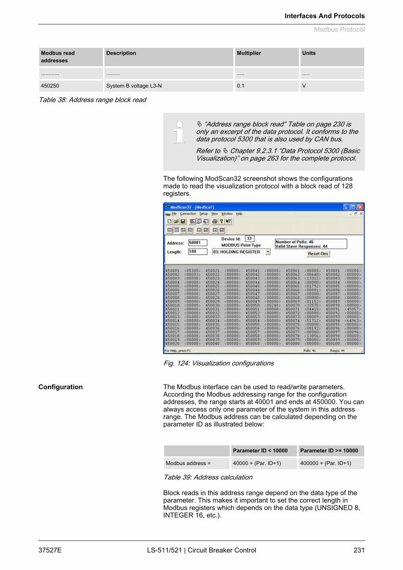
Modbus readaddresses
Description Multiplier Units
............ ......... ..... .....
450250 System B voltage L3-N 0.1 V
Table 38: Address range block read
Ä “Address range block read” Table on page 230 isonly an excerpt of the data protocol. It conforms to thedata protocol 5300 that is also used by CAN bus.Refer to Ä Chapter 9.2.3.1 “Data Protocol 5300 (BasicVisualization)” on page 263 for the complete protocol.
The following ModScan32 screenshot shows the configurationsmade to read the visualization protocol with a block read of 128registers.
Fig. 124: Visualization configurations
The Modbus interface can be used to read/write parameters.According the Modbus addressing range for the configurationaddresses, the range starts at 40001 and ends at 450000. You canalways access only one parameter of the system in this addressrange. The Modbus address can be calculated depending on theparameter ID as illustrated below:
Parameter ID < 10000 Parameter ID >= 10000
Modbus address = 40000 + (Par. ID+1) 400000 + (Par. ID+1)
Table 39: Address calculation
Block reads in this address range depend on the data type of theparameter. This makes it important to set the correct length inModbus registers which depends on the data type (UNSIGNED 8,INTEGER 16, etc.).
Configuration
Interfaces And Protocols
Modbus Protocol
37527E LS-511/521 | Circuit Breaker Control 231

Refer to Ä “Data types” Table on page 232 for more information.
Types Modbus registers
UNSIGNED 8 1
UNSIGNED 16 1
INTEGER 16 1
UNSIGNED 32 2
INTEGER 32 2
LOGMAN 7
TEXT/X X/2
Table 40: Data types
Interfaces And Protocols
Modbus Protocol
37527ELS-511/521 | Circuit Breaker Control232

8 Technical Specifications8.1 Technical Data
Fig. 125: Product label
1 P/N Item number
2 REV Item revision number
3 S/N Serial number (numerical)
4 S/N Serial number (barcode)
5 S/N Date of production (year-month)
6 Type Description (short)
7 Type Description (long)
8 Details Technical data
9 Approval Approvals
8.1.1 Measuring ValuesMeasuring voltage / 120 V
Rated value (Vrated) 69/120 Vac
Maximum value (Vmax) max. 86/150 Vac
Rated voltage phase – ground 150 Vac
Rated surge voltage (Vsurge) 2.5 kV
Measuring voltage / 480 V
Rated value (Vrated) 277/480 Vac
Maximum value (Vmax) max. 346/600 Vac
Rated voltage phase – ground 300 Vac
Rated surge voltage (Vsurge) 4.0 kV
Linear measuring range 1.25 × Vrated
Product label
Voltages
Technical Specifications
Technical Data > Measuring Values
37527E LS-511/521 | Circuit Breaker Control 233

Measuring frequency 50/60 Hz (30.0 to 85.0Hz)
Accuracy Class 1
Input resistance per path 120 V 0.498 MΩ
480 V 2.0 MΩ
Maximum power consumption per path < 0.15 W
Measuring inputs Isolated
Measuring current [1] Rated value (Irated) ../1 A
[5] Rated value (Irated) ../5 A
Accuracy Class 1
Linear measuring range System A approx. 1.5× Irated
Maximum power consumption per path < 0.15 VA
Rated short-time current (1 s) [1] 50.0 × Irated
[5] 10.0 × Irated
8.1.2 Ambient VariablesPower supply 12/24 Vdc (8 to 40.0 Vdc)
Intrinsic consumption LS-511: ~ 5 W
LS-521: ~ 6 W
Degree of pollution 2
Maximum elevation 2,000 m ASL
Overvoltage (≤ 2 min) 80 Vdc
Reverse voltage protection Full supply range
Input capacitance LS-511: 660 uF
LS-521: 660 uF
8.1.3 Inputs/OutputsDiscrete inputs Isolated
Input range (Vcont. dig. input) Rated voltage
12/24 Vdc (8 to 40.0 Vdc)
Input resistance approx. 20 kΩ
Discrete outputs Potential free
Contact material AgCdO
Currents
Discrete inputs
Discrete outputs
Technical Specifications
Technical Data > Inputs/Outputs
37527ELS-511/521 | Circuit Breaker Control234

General purpose (GP) (Vcont,
relays)AC 2.00 Aac@250 Vac
DC 2.00 Adc@24 Vdc
0.36 Adc@125 Vdc
0.18 Adc@250 Vdc
Pilot duty (PD) (Vcont, relays) AC B300
DC 1.00 Adc@24 Vdc
0.22 Adc@125 Vdc
0.10 Adc@250 Vdc
8.1.4 InterfaceService Port interface Not isolated
Proprietary interface Connect only with WoodwardDPC cable
RS-485 interface Isolated
Insulation voltage (continuously) 100 Vac
Insulation test voltage (≤ 5 s) 1000 Vac
Version RS-485 Standard
Operation Half-duplex
CAN bus interface Isolated
Insulation voltage (continuously) 100 Vac
Insulation test voltage (≤ 5 s) 1000 Vac
Version CAN bus
Internal line termination Not available
8.1.5 BatteryType Lithium
Life span (operation without powersupply)
approx. 5 years
Battery field replacement Not allowed
8.1.6 HousingType Plastic easYpack
Sheet metal Custom
Service Port interface
RS-485 interface
CAN bus interface
Housing type
Technical Specifications
Technical Data > Housing
37527E LS-511/521 | Circuit Breaker Control 235

Dimensions (W × H ×D)
Plastic 219 × 171 × 61 mm
Sheet metal 190 × 167 × 47 mm
Front cutout (W × H) Plastic 186 [+1.1] × 138 [+1.0] mm
Wiring Screw-plug-terminals 2.5 mm²
Recommendedlocked torque
4 inch pounds / 0.5 Nm
Use 60/75 °C copper wire only
Use class 1 wire only or equivalent
Weight Plastic approx. 850 g
Sheet metal approx. 840 g
Protection system Plastic IP54 from front with clamp fas‐teners
IP66 from front with screw kit
IP20 from back
Sheet metal IP20
Front foil (plastichousing)
Insulating surface
8.1.7 ApprovalsEMC test (CE) Tested according to applicable EN guidelines
Listings CE marking
UL / cUL, Ordinary Locations, File No.: 231544
GOST-R
Marine Type approval Lloyds Register (LR)
Design assessment American Bureau of Shipping(ABS)
8.1.8 Generic NoteAccuracy Referred to full scale value
8.2 Environmental DataFrequency range - sine sweep 5 Hz to 100 Hz
Acceleration 4 G
Standards EN 60255-21-1 (EN 60068-2-6, Fc)
Lloyd’s Register, Vibration Test2
SAEJ1455 Chassis Data
Protection
Vibration
Technical Specifications
Environmental Data
37527ELS-511/521 | Circuit Breaker Control236
Frequency range - random 10 Hz to 500 Hz
Power intensity 0.015 G²/Hz
RMS value 1.04 Grms
Standards MIL-STD 810F, M514.5A, Cat.4,
Truck/Trailer tracked-restrained
Cargo, Fig. 514.5-C1
Shock 40 G, Saw tooth pulse, 11 ms
Standards EN 60255-21-2
MIL-STD 810F, M516.5, Procedure 1
Cold, Dry Heat (storage) -30 °C (-22 °F) / 80 °C (176 °F)
Cold, Dry Heat (operating) -20 °C (-4 °F) / 70 °C (158 °F)
Standards IEC 60068-2-2, Test Bb and Bd
IEC 60068-2-1, Test Ab and Ad
MILSTD -810D, M501.2 Induced,M502.2 Cold
LR Dry Heat, Cold, Envt 2,4, DNV Dryheat, Cold Class A,C
Humidity 95%, non condensing
Standards MIL-STD 810D, M507.2, PII
Marine environmental categories Lloyd’s Register of Shipping (LRS):
ENV1, ENV2, ENV3 and ENV4
8.3 AccuracyMeasuring value Display Accuracy Measuring start Notes
Frequency
System A 40.0 to 85.0 Hz 0.1 % (of 85 Hz) 5 % (of PT secondaryvoltage setting) 1
System B
Voltage
Wye system A / systemA
0 to 650 kV 1 % (of 120/480 V) 2 1.5 % (of PT secondaryvoltage setting) 1
Shock
Temperature
Humidity
Marine environmental categories
Technical Specifications
Accuracy
37527E LS-511/521 | Circuit Breaker Control 237
Measuring value Display Accuracy Measuring start Notes
Delta system A / systemB
2 % (of PT secondaryvoltage setting) 1
Current
System A 0 to 32,000 A 1 % (of 1/5 A) 3 1 % (of 1/5 A) 3
Max. value
Real power
Actual total real powervalue
-2 to 2 GW 2 % (of 120/480 V *1/5 A) 2/3
Measuring starts whenvoltage is recognized
Reactive power
Actual value in L1, L2,L3
-2 to 2 Gvar 2 % (of 120/480 V *1/5 A) 2/3
Measuring starts whenvoltage is recognized
Power factor
Actual value powerfactor L1
lagging 0.00 to 1.00 toleading 0.00
2 % 2 % (of 1/5 A) 3 1.00 is displayed formeasuring values belowthe measuring start
Miscellaneous
Battery voltage 8 to 40 V 1 % (of 24 V)
Phase angle -180 to 180 ° 1.25 % (of PT secondaryvolt. setting)
180 ° is displayed formeasuring values belowmeasuring start
1 Setting of the parameter for the PT secondary ratedvoltage2 Depending on the used measuring inputs(120/480 V)3 Depending on the CT input hardware (1/5 A) of therespective unit
The reference conditions for measuring the accuracyare listed below.
Input voltage Sinusoidal rated voltage
Input current Sinusoidal rated current
Frequency Rated frequency +/- 2 %
Reference conditions
Technical Specifications
Accuracy
37527ELS-511/521 | Circuit Breaker Control238
Power supply Rated voltage +/- 2 %
Power factor (cos φ) 1.00
Ambient temperature 23 °C +/- 2 K
Warm-up period 20 minutes
Technical Specifications
Accuracy
37527E LS-511/521 | Circuit Breaker Control 239

Technical Specifications
Accuracy
37527ELS-511/521 | Circuit Breaker Control240

9 Appendix9.1 Characteristics9.1.1 Triggering Characteristics
This triggering characteristic is used for system A, system B andbattery overvoltage, system A and system B overfrequency.
Fig. 126: Two-level overshoot monitoring
Two-level overshoot monitoring
Appendix
Characteristics > Triggering Characteristics
37527E LS-511/521 | Circuit Breaker Control 241
This triggering characteristic is used for system A, system B andbattery undervoltage, system A and system B underfrequency.
Fig. 127: Two-level undershoot monitoring
Two-level undershoot monitoring
Appendix
Characteristics > Triggering Characteristics
37527ELS-511/521 | Circuit Breaker Control242
This triggering characteristic is used for system A voltage asym‐metry monitoring.
Fig. 128: One-level asymmetry monitoring
9.2 Data Protocols9.2.1 CANopen/Modbus9.2.1.1 Data Protocol 5301 (Basic Visualization)
Modbus CAN Param‐eter ID
Description Multiplier Units
Mod‐iconstartaddr.
Startaddr.(*1)
Databyte 0(Mux)
Databyte
50001 50000 0 1,2 Protocol ID, always 5301
50002 50001 0 3,4,5,6 136 System A total reactive power 1 Var
50004 50003 1 1,2 160 System A power factor (cos.phi) 0.001
50005 50004 1 3,4,5,6 170 System A average wye voltage 0.1 V
50007 50006 2 1,2 144 System A frequency 0.01 Hz
50008 50007 2 3,4,5,6 171 System A average delta voltage 0.1 V
One-level asymmetry monitoring
Appendix
Data Protocols > CANopen/Modbus > Data Protocol 5301 (Basic ...
37527E LS-511/521 | Circuit Breaker Control 243

Modbus CAN Param‐eter ID
Description Multiplier Units
Mod‐iconstartaddr.
Startaddr.(*1)
Databyte 0(Mux)
Databyte
50010 50009 3 1,2 10202 Operation modes
13280 = CB A request
13264 = Unloading CB A
13210 = CB A Dead bus closure
13260 = Synchronization CB A
13205 = Mains settling time running
13257 = Open CB A
13279 = Synchronization network close CB A
13265 = Synchronization PERMISSIVE
13266 = Synchronization CHECK
13267 = Synchronization OFF
13286 = Synchronization segments close CB A
50011 50010 3 3,4,5,6 135 System A total active power 1 W
50013 50012 4 1,2 10107 Discrete outputs 1 to 6
Relay-Output 1 (inverted) Mask: 8000h Bit
Relay-Output 2 Mask: 4000h Bit
Relay-Output 3 Mask: 2000h Bit
Relay-Output 4 Mask: 1000h Bit
Relay-Output 5 Mask: 0800h Bit
Relay-Output 6 Mask: 0400h Bit
internal Mask: 0200h Bit
internal Mask: 0100h Bit
internal Mask: 0080h Bit
internal Mask: 0040h Bit
internal Mask: 0020h Bit
internal Mask: 0010h Bit
internal Mask: 0008h Bit
internal Mask: 0004h Bit
internal Mask: 0002h Bit
internal Mask: 0001h Bit
50014 50013 4 3,4,5,6 185 System A current average 0.001 A
50016 50015 5 1,2 8018 internal Mask: 0001h Bit
internal Mask: 0002h Bit
internal Mask: 0004h Bit
internal Mask: 0008h Bit
Appendix
Data Protocols > CANopen/Modbus > Data Protocol 5301 (Basic ...
37527ELS-511/521 | Circuit Breaker Control244
Modbus CAN Param‐eter ID
Description Multiplier Units
Mod‐iconstartaddr.
Startaddr.(*1)
Databyte 0(Mux)
Databyte
internal Mask: 0010h Bit
internal Mask: 0020h Bit
internal Mask: 0040h Bit
internal Mask: 0080h Bit
28.01 Command to CB-control 1 (OR'ed) Mask: 0100h Bit
28.02 Command to CB-control 2 (OR'ed) Mask: 0200h Bit
28.03 Command to CB-control 3 (OR'ed) Mask: 0400h Bit
28.04 Command to CB-control 4 (OR'ed) Mask: 0800h Bit
28.05 Command to CB-control 5 (OR'ed) Mask: 1000h Bit
28.06 Command to CB-control 6 (OR'ed) Mask: 2000h Bit
internal Mask: 4000h Bit
internal Mask: 8000h Bit
50017 50016 5 3,4,5,6 111 System A current 1 0.001 A
50019 50018 6 1,2 10110 Battery voltage 0.1 V
50020 50019 6 3,4,5,6 112 System A current 2 0.001 A
50022 50021 7 1,2 10146 internal Mask: 0001h Bit
internal Mask: 0002h Bit
internal Mask: 0004h Bit
11.07 Active second Mask: 0008h Bit
11.06 Active minute Mask: 0010h Bit
11.05 Active hour Mask: 0020h Bit
11.04 Active day in month Mask: 0040h Bit
11.03 Active weekday Mask: 0080h Bit
11.02 Time 2 overrun Mask: 0100h Bit
11.01 Time 1 overrun Mask: 0200h Bit
internal Mask: 0400h Bit
04.05 Acknowledge was executed Mask: 0800h Bit
01.09 Shutdown alarm active (alarm C-F) Mask: 1000h Bit
internal Mask: 2000h Bit
internal Mask: 4000h Bit
internal Mask: 8000h Bit
50023 50022 7 3,4,5,6 113 System A current 3 0.001 A
50025 50024 8 1,2 10107 00.41 LM Relay 1 Mask: 8000h Bit
00.42 LM Relay 2 Mask: 4000h Bit
Appendix
Data Protocols > CANopen/Modbus > Data Protocol 5301 (Basic ...
37527E LS-511/521 | Circuit Breaker Control 245
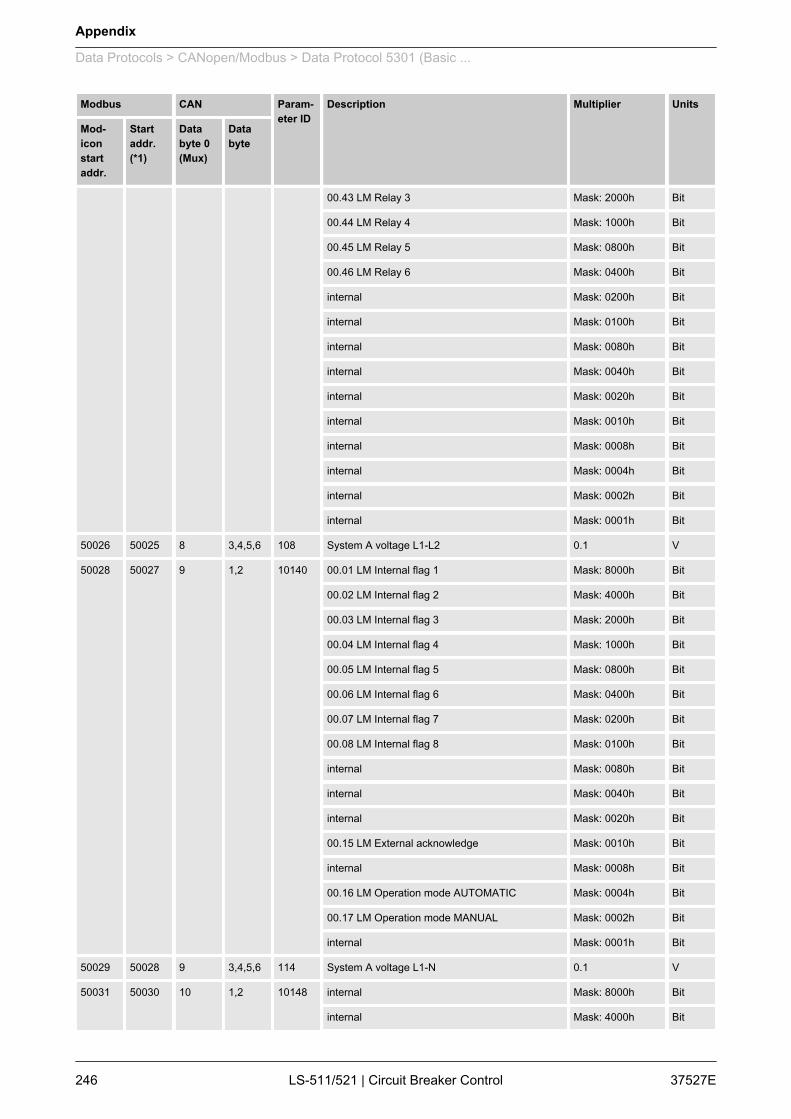
Modbus CAN Param‐eter ID
Description Multiplier Units
Mod‐iconstartaddr.
Startaddr.(*1)
Databyte 0(Mux)
Databyte
00.43 LM Relay 3 Mask: 2000h Bit
00.44 LM Relay 4 Mask: 1000h Bit
00.45 LM Relay 5 Mask: 0800h Bit
00.46 LM Relay 6 Mask: 0400h Bit
internal Mask: 0200h Bit
internal Mask: 0100h Bit
internal Mask: 0080h Bit
internal Mask: 0040h Bit
internal Mask: 0020h Bit
internal Mask: 0010h Bit
internal Mask: 0008h Bit
internal Mask: 0004h Bit
internal Mask: 0002h Bit
internal Mask: 0001h Bit
50026 50025 8 3,4,5,6 108 System A voltage L1-L2 0.1 V
50028 50027 9 1,2 10140 00.01 LM Internal flag 1 Mask: 8000h Bit
00.02 LM Internal flag 2 Mask: 4000h Bit
00.03 LM Internal flag 3 Mask: 2000h Bit
00.04 LM Internal flag 4 Mask: 1000h Bit
00.05 LM Internal flag 5 Mask: 0800h Bit
00.06 LM Internal flag 6 Mask: 0400h Bit
00.07 LM Internal flag 7 Mask: 0200h Bit
00.08 LM Internal flag 8 Mask: 0100h Bit
internal Mask: 0080h Bit
internal Mask: 0040h Bit
internal Mask: 0020h Bit
00.15 LM External acknowledge Mask: 0010h Bit
internal Mask: 0008h Bit
00.16 LM Operation mode AUTOMATIC Mask: 0004h Bit
00.17 LM Operation mode MANUAL Mask: 0002h Bit
internal Mask: 0001h Bit
50029 50028 9 3,4,5,6 114 System A voltage L1-N 0.1 V
50031 50030 10 1,2 10148 internal Mask: 8000h Bit
internal Mask: 4000h Bit
Appendix
Data Protocols > CANopen/Modbus > Data Protocol 5301 (Basic ...
37527ELS-511/521 | Circuit Breaker Control246

Modbus CAN Param‐eter ID
Description Multiplier Units
Mod‐iconstartaddr.
Startaddr.(*1)
Databyte 0(Mux)
Databyte
internal Mask: 2000h Bit
internal Mask: 1000h Bit
04.04 Lamp test Mask: 0800h Bit
01.10 Centralized alarms active (alarm B-F) Mask: 0400h Bit
01.07 All alarm classes are active Mask: 0200h Bit
01.08 Warning alarms active (alarm A, B) Mask: 0100h Bit
internal Mask: 0080h Bit
internal Mask: 0040h Bit
internal Mask: 0020h Bit
internal Mask: 0010h Bit
internal Mask: 0008h Bit
internal Mask: 0004h Bit
internal Mask: 0002h Bit
internal Mask: 0001h Bit
50032 50031 10 3,4,5,6 109 System A voltage L2-L3 0.1 V
50034 50033 11 1,2 10150 internal Mask: 8000h Bit
internal Mask: 4000h Bit
internal Mask: 2000h Bit
internal Mask: 1000h Bit
internal Mask: 0800h Bit
internal Mask: 0400h Bit
00.30 LM Internal flag 9 Mask: 0200h Bit
00.31 LM Internal flag 10 Mask: 0100h Bit
00.32 LM Internal flag 11 Mask: 0080h Bit
00.33 LM Internal flag 12 Mask: 0040h Bit
00.34 LM Internal flag 13 Mask: 0020h Bit
00.35 LM Internal flag 14 Mask: 0010h Bit
00.36 LM Internal flag 15 Mask: 0008h Bit
00.37 LM Internal flag 16 Mask: 0004h Bit
internal Mask: 0002h Bit
internal Mask: 0001h Bit
50035 50034 11 3,4,5,6 115 System A voltage L2-N 0.1 V
50037 50036 12 1,2 10160 internal Mask: 8000h Bit
internal Mask: 4000h Bit
Appendix
Data Protocols > CANopen/Modbus > Data Protocol 5301 (Basic ...
37527E LS-511/521 | Circuit Breaker Control 247
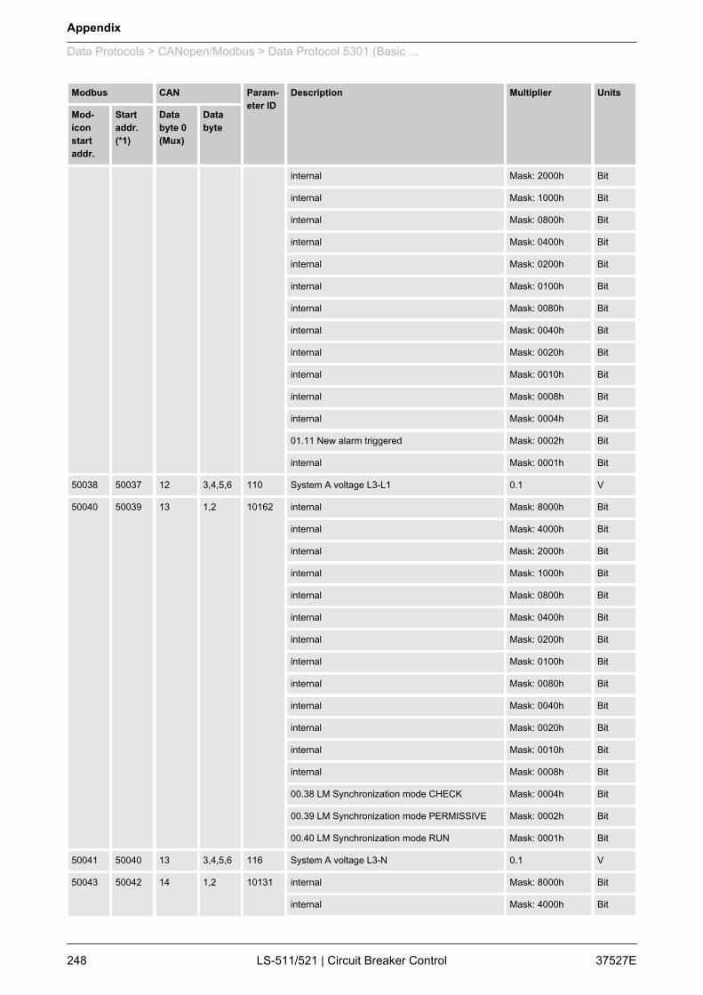
Modbus CAN Param‐eter ID
Description Multiplier Units
Mod‐iconstartaddr.
Startaddr.(*1)
Databyte 0(Mux)
Databyte
internal Mask: 2000h Bit
internal Mask: 1000h Bit
internal Mask: 0800h Bit
internal Mask: 0400h Bit
internal Mask: 0200h Bit
internal Mask: 0100h Bit
internal Mask: 0080h Bit
internal Mask: 0040h Bit
internal Mask: 0020h Bit
internal Mask: 0010h Bit
internal Mask: 0008h Bit
internal Mask: 0004h Bit
01.11 New alarm triggered Mask: 0002h Bit
internal Mask: 0001h Bit
50038 50037 12 3,4,5,6 110 System A voltage L3-L1 0.1 V
50040 50039 13 1,2 10162 internal Mask: 8000h Bit
internal Mask: 4000h Bit
internal Mask: 2000h Bit
internal Mask: 1000h Bit
internal Mask: 0800h Bit
internal Mask: 0400h Bit
internal Mask: 0200h Bit
internal Mask: 0100h Bit
internal Mask: 0080h Bit
internal Mask: 0040h Bit
internal Mask: 0020h Bit
internal Mask: 0010h Bit
internal Mask: 0008h Bit
00.38 LM Synchronization mode CHECK Mask: 0004h Bit
00.39 LM Synchronization mode PERMISSIVE Mask: 0002h Bit
00.40 LM Synchronization mode RUN Mask: 0001h Bit
50041 50040 13 3,4,5,6 116 System A voltage L3-N 0.1 V
50043 50042 14 1,2 10131 internal Mask: 8000h Bit
internal Mask: 4000h Bit
Appendix
Data Protocols > CANopen/Modbus > Data Protocol 5301 (Basic ...
37527ELS-511/521 | Circuit Breaker Control248
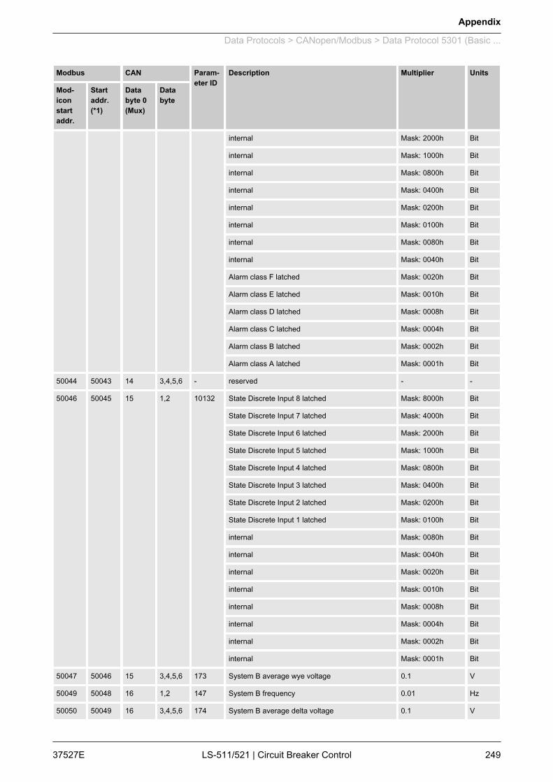
Modbus CAN Param‐eter ID
Description Multiplier Units
Mod‐iconstartaddr.
Startaddr.(*1)
Databyte 0(Mux)
Databyte
internal Mask: 2000h Bit
internal Mask: 1000h Bit
internal Mask: 0800h Bit
internal Mask: 0400h Bit
internal Mask: 0200h Bit
internal Mask: 0100h Bit
internal Mask: 0080h Bit
internal Mask: 0040h Bit
Alarm class F latched Mask: 0020h Bit
Alarm class E latched Mask: 0010h Bit
Alarm class D latched Mask: 0008h Bit
Alarm class C latched Mask: 0004h Bit
Alarm class B latched Mask: 0002h Bit
Alarm class A latched Mask: 0001h Bit
50044 50043 14 3,4,5,6 - reserved - -
50046 50045 15 1,2 10132 State Discrete Input 8 latched Mask: 8000h Bit
State Discrete Input 7 latched Mask: 4000h Bit
State Discrete Input 6 latched Mask: 2000h Bit
State Discrete Input 5 latched Mask: 1000h Bit
State Discrete Input 4 latched Mask: 0800h Bit
State Discrete Input 3 latched Mask: 0400h Bit
State Discrete Input 2 latched Mask: 0200h Bit
State Discrete Input 1 latched Mask: 0100h Bit
internal Mask: 0080h Bit
internal Mask: 0040h Bit
internal Mask: 0020h Bit
internal Mask: 0010h Bit
internal Mask: 0008h Bit
internal Mask: 0004h Bit
internal Mask: 0002h Bit
internal Mask: 0001h Bit
50047 50046 15 3,4,5,6 173 System B average wye voltage 0.1 V
50049 50048 16 1,2 147 System B frequency 0.01 Hz
50050 50049 16 3,4,5,6 174 System B average delta voltage 0.1 V
Appendix
Data Protocols > CANopen/Modbus > Data Protocol 5301 (Basic ...
37527E LS-511/521 | Circuit Breaker Control 249
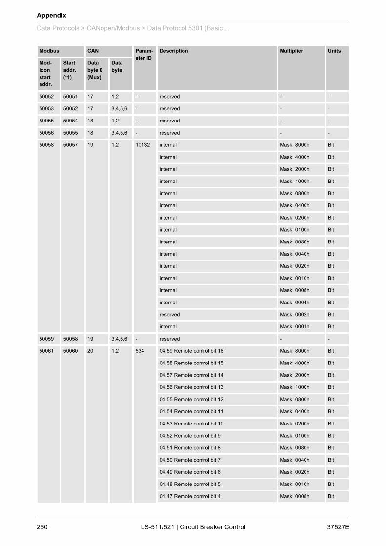
Modbus CAN Param‐eter ID
Description Multiplier Units
Mod‐iconstartaddr.
Startaddr.(*1)
Databyte 0(Mux)
Databyte
50052 50051 17 1,2 - reserved - -
50053 50052 17 3,4,5,6 - reserved - -
50055 50054 18 1,2 - reserved - -
50056 50055 18 3,4,5,6 - reserved - -
50058 50057 19 1,2 10132 internal Mask: 8000h Bit
internal Mask: 4000h Bit
internal Mask: 2000h Bit
internal Mask: 1000h Bit
internal Mask: 0800h Bit
internal Mask: 0400h Bit
internal Mask: 0200h Bit
internal Mask: 0100h Bit
internal Mask: 0080h Bit
internal Mask: 0040h Bit
internal Mask: 0020h Bit
internal Mask: 0010h Bit
internal Mask: 0008h Bit
internal Mask: 0004h Bit
reserved Mask: 0002h Bit
internal Mask: 0001h Bit
50059 50058 19 3,4,5,6 - reserved - -
50061 50060 20 1,2 534 04.59 Remote control bit 16 Mask: 8000h Bit
04.58 Remote control bit 15 Mask: 4000h Bit
04.57 Remote control bit 14 Mask: 2000h Bit
04.56 Remote control bit 13 Mask: 1000h Bit
04.55 Remote control bit 12 Mask: 0800h Bit
04.54 Remote control bit 11 Mask: 0400h Bit
04.53 Remote control bit 10 Mask: 0200h Bit
04.52 Remote control bit 9 Mask: 0100h Bit
04.51 Remote control bit 8 Mask: 0080h Bit
04.50 Remote control bit 7 Mask: 0040h Bit
04.49 Remote control bit 6 Mask: 0020h Bit
04.48 Remote control bit 5 Mask: 0010h Bit
04.47 Remote control bit 4 Mask: 0008h Bit
Appendix
Data Protocols > CANopen/Modbus > Data Protocol 5301 (Basic ...
37527ELS-511/521 | Circuit Breaker Control250
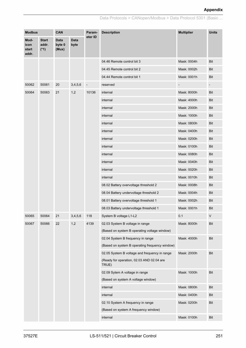
Modbus CAN Param‐eter ID
Description Multiplier Units
Mod‐iconstartaddr.
Startaddr.(*1)
Databyte 0(Mux)
Databyte
04.46 Remote control bit 3 Mask: 0004h Bit
04.45 Remote control bit 2 Mask: 0002h Bit
04.44 Remote control bit 1 Mask: 0001h Bit
50062 50061 20 3,4,5,6 - reserved - -
50064 50063 21 1,2 10136 internal Mask: 8000h Bit
internal Mask: 4000h Bit
internal Mask: 2000h Bit
internal Mask: 1000h Bit
internal Mask: 0800h Bit
internal Mask: 0400h Bit
internal Mask: 0200h Bit
internal Mask: 0100h Bit
internal Mask: 0080h Bit
internal Mask: 0040h Bit
internal Mask: 0020h Bit
internal Mask: 0010h Bit
08.02 Battery overvoltage threshold 2 Mask: 0008h Bit
08.04 Battery undervoltage threshold 2 Mask: 0004h Bit
08.01 Battery overvoltage threshold 1 Mask: 0002h Bit
08.03 Battery undervoltage threshold 1 Mask: 0001h Bit
50065 50064 21 3,4,5,6 118 System B voltage L1-L2 0.1 V
50067 50066 22 1,2 4139 02.03 System B voltage in range
(Based on system B operating voltage window)
Mask: 8000h Bit
02.04 System B frequency in range
(Based on system B operating frequency window)
Mask: 4000h Bit
02.05 System B voltage and frequency in range
(Ready for operation, 02.03 AND 02.04 areTRUE)
Mask: 2000h Bit
02.09 Sytem A voltage in range
(Based on system A voltage window)
Mask: 1000h Bit
internal Mask: 0800h Bit
internal Mask: 0400h Bit
02.10 System A frequency in range
(Based on system A frequency window)
Mask: 0200h Bit
internal Mask: 0100h Bit
Appendix
Data Protocols > CANopen/Modbus > Data Protocol 5301 (Basic ...
37527E LS-511/521 | Circuit Breaker Control 251
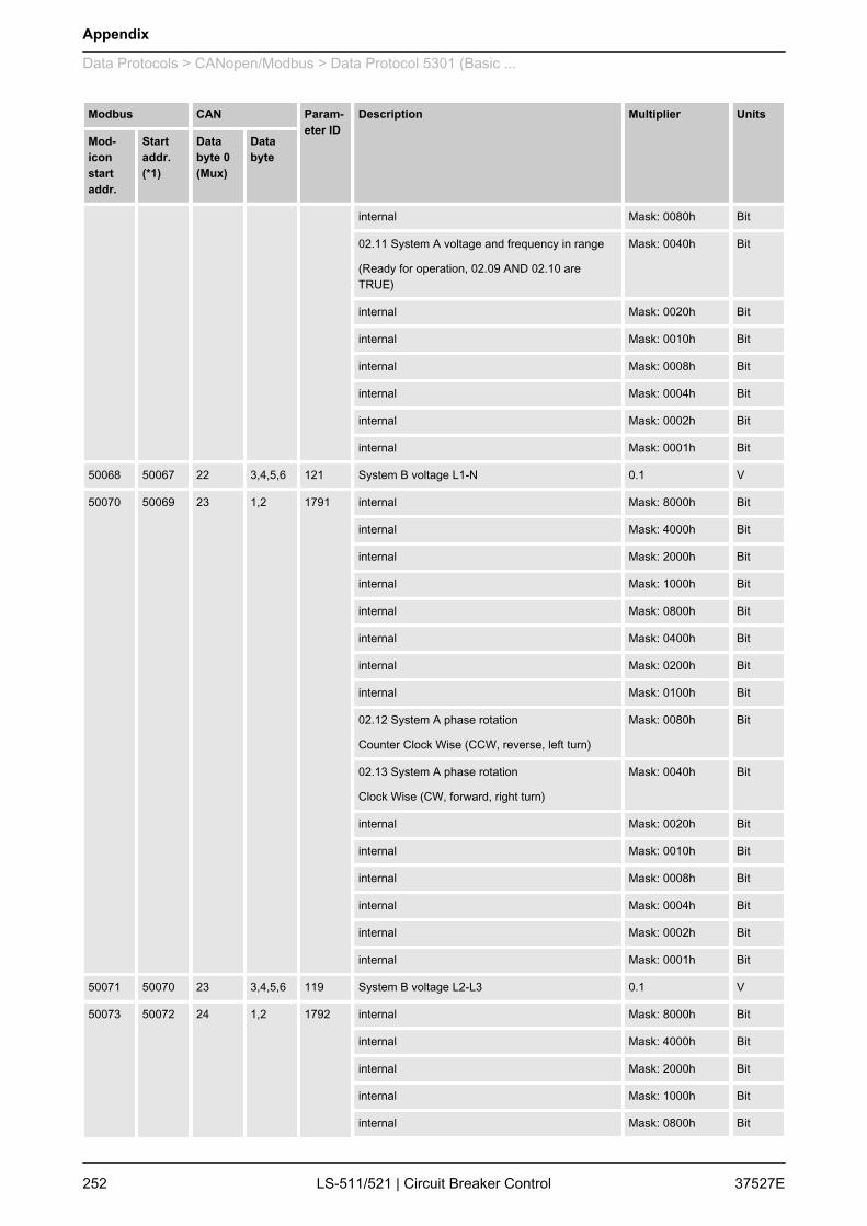
Modbus CAN Param‐eter ID
Description Multiplier Units
Mod‐iconstartaddr.
Startaddr.(*1)
Databyte 0(Mux)
Databyte
internal Mask: 0080h Bit
02.11 System A voltage and frequency in range
(Ready for operation, 02.09 AND 02.10 areTRUE)
Mask: 0040h Bit
internal Mask: 0020h Bit
internal Mask: 0010h Bit
internal Mask: 0008h Bit
internal Mask: 0004h Bit
internal Mask: 0002h Bit
internal Mask: 0001h Bit
50068 50067 22 3,4,5,6 121 System B voltage L1-N 0.1 V
50070 50069 23 1,2 1791 internal Mask: 8000h Bit
internal Mask: 4000h Bit
internal Mask: 2000h Bit
internal Mask: 1000h Bit
internal Mask: 0800h Bit
internal Mask: 0400h Bit
internal Mask: 0200h Bit
internal Mask: 0100h Bit
02.12 System A phase rotation
Counter Clock Wise (CCW, reverse, left turn)
Mask: 0080h Bit
02.13 System A phase rotation
Clock Wise (CW, forward, right turn)
Mask: 0040h Bit
internal Mask: 0020h Bit
internal Mask: 0010h Bit
internal Mask: 0008h Bit
internal Mask: 0004h Bit
internal Mask: 0002h Bit
internal Mask: 0001h Bit
50071 50070 23 3,4,5,6 119 System B voltage L2-L3 0.1 V
50073 50072 24 1,2 1792 internal Mask: 8000h Bit
internal Mask: 4000h Bit
internal Mask: 2000h Bit
internal Mask: 1000h Bit
internal Mask: 0800h Bit
Appendix
Data Protocols > CANopen/Modbus > Data Protocol 5301 (Basic ...
37527ELS-511/521 | Circuit Breaker Control252

Modbus CAN Param‐eter ID
Description Multiplier Units
Mod‐iconstartaddr.
Startaddr.(*1)
Databyte 0(Mux)
Databyte
internal Mask: 0400h Bit
internal Mask: 0200h Bit
internal Mask: 0100h Bit
02.14 System B phase rotation
Counter Clock Wise (CCW, reverse, left turn)
Mask: 0080h Bit
02.15 System B phase rotation
Clock Wise (CW, forward, right turn)
Mask: 0040h Bit
internal Mask: 0020h Bit
internal Mask: 0010h Bit
internal Mask: 0008h Bit
internal Mask: 0004h Bit
internal Mask: 0002h Bit
internal Mask: 0001h Bit
50074 50073 24 3,4,5,6 122 System B voltage L2-N 0.1 V
50076 50075 25 1,2 internal Mask: 8000h Bit
04.63 Synchr. Segm Closure Pr. is act Mask: 4000h Bit
internal Mask: 2000h Bit
02.28 Synch. Check Relay Mask: 1000h Bit
02.29 Synch. Condition Mask: 0800h Bit
02.30 Dead Bus Closure Condition Mask: 0400h Bit
internal Mask: 0200h Bit
internal Mask: 0100h Bit
internal Mask: 0080h Bit
internal Mask: 0040h Bit
internal Mask: 0020h Bit
internal Mask: 0010h Bit
internal Mask: 0008h Bit
internal Mask: 0004h Bit
internal Mask: 0002h Bit
internal Mask: 0001h Bit
50077 50076 25 3,4,5,6 120 System B voltage L3-L1 0.1 V
50079 50078 26 1,2 10149 reserved Mask: 8000h Bit
08.31 Timeout synchronization CB A Mask: 4000h Bit
internal Mask: 2000h Bit
Appendix
Data Protocols > CANopen/Modbus > Data Protocol 5301 (Basic ...
37527E LS-511/521 | Circuit Breaker Control 253
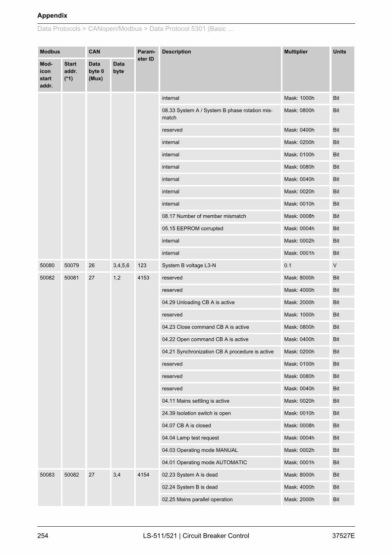
Modbus CAN Param‐eter ID
Description Multiplier Units
Mod‐iconstartaddr.
Startaddr.(*1)
Databyte 0(Mux)
Databyte
internal Mask: 1000h Bit
08.33 System A / System B phase rotation mis‐match
Mask: 0800h Bit
reserved Mask: 0400h Bit
internal Mask: 0200h Bit
internal Mask: 0100h Bit
internal Mask: 0080h Bit
internal Mask: 0040h Bit
internal Mask: 0020h Bit
internal Mask: 0010h Bit
08.17 Number of member mismatch Mask: 0008h Bit
05.15 EEPROM corrupted Mask: 0004h Bit
internal Mask: 0002h Bit
internal Mask: 0001h Bit
50080 50079 26 3,4,5,6 123 System B voltage L3-N 0.1 V
50082 50081 27 1,2 4153 reserved Mask: 8000h Bit
reserved Mask: 4000h Bit
04.29 Unloading CB A is active Mask: 2000h Bit
reserved Mask: 1000h Bit
04.23 Close command CB A is active Mask: 0800h Bit
04.22 Open command CB A is active Mask: 0400h Bit
04.21 Synchronization CB A procedure is active Mask: 0200h Bit
reserved Mask: 0100h Bit
reserved Mask: 0080h Bit
reserved Mask: 0040h Bit
04.11 Mains settling is active Mask: 0020h Bit
24.39 Isolation switch is open Mask: 0010h Bit
04.07 CB A is closed Mask: 0008h Bit
04.04 Lamp test request Mask: 0004h Bit
04.03 Operating mode MANUAL Mask: 0002h Bit
04.01 Operating mode AUTOMATIC Mask: 0001h Bit
50083 50082 27 3,4 4154 02.23 System A is dead Mask: 8000h Bit
02.24 System B is dead Mask: 4000h Bit
02.25 Mains parallel operation Mask: 2000h Bit
Appendix
Data Protocols > CANopen/Modbus > Data Protocol 5301 (Basic ...
37527ELS-511/521 | Circuit Breaker Control254
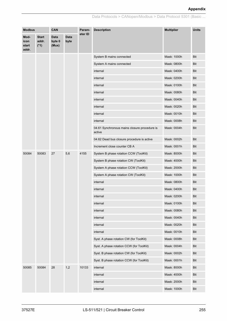
Modbus CAN Param‐eter ID
Description Multiplier Units
Mod‐iconstartaddr.
Startaddr.(*1)
Databyte 0(Mux)
Databyte
System B mains connected Mask: 1000h Bit
System A mains connected Mask: 0800h Bit
internal Mask: 0400h Bit
internal Mask: 0200h Bit
internal Mask: 0100h Bit
internal Mask: 0080h Bit
internal Mask: 0040h Bit
internal Mask: 0020h Bit
internal Mask: 0010h Bit
internal Mask: 0008h Bit
04.61 Synchronous mains closure procedure isactive
Mask: 0004h Bit
04.62 Dead bus closure procedure is active Mask: 0002h Bit
Increment close counter CB A Mask: 0001h Bit
50084 50083 27 5,6 4155 System B phase rotation CCW (ToolKit) Mask: 8000h Bit
System B phase rotation CW (ToolKit) Mask: 4000h Bit
System A phase rotation CCW (ToolKit) Mask: 2000h Bit
System A phase rotation CW (ToolKit) Mask: 1000h Bit
internal Mask: 0800h Bit
internal Mask: 0400h Bit
internal Mask: 0200h Bit
internal Mask: 0100h Bit
internal Mask: 0080h Bit
internal Mask: 0040h Bit
internal Mask: 0020h Bit
internal Mask: 0010h Bit
Syst. A phase rotation CW (for ToolKit) Mask: 0008h Bit
Syst. A phase rotation CCW (for ToolKit) Mask: 0004h Bit
Syst. B phase rotation CW (for ToolKit) Mask: 0002h Bit
Syst. B phase rotation CCW (for ToolKit) Mask: 0001h Bit
50085 50084 28 1,2 10133 internal Mask: 8000h Bit
internal Mask: 4000h Bit
internal Mask: 2000h Bit
internal Mask: 1000h Bit
Appendix
Data Protocols > CANopen/Modbus > Data Protocol 5301 (Basic ...
37527E LS-511/521 | Circuit Breaker Control 255
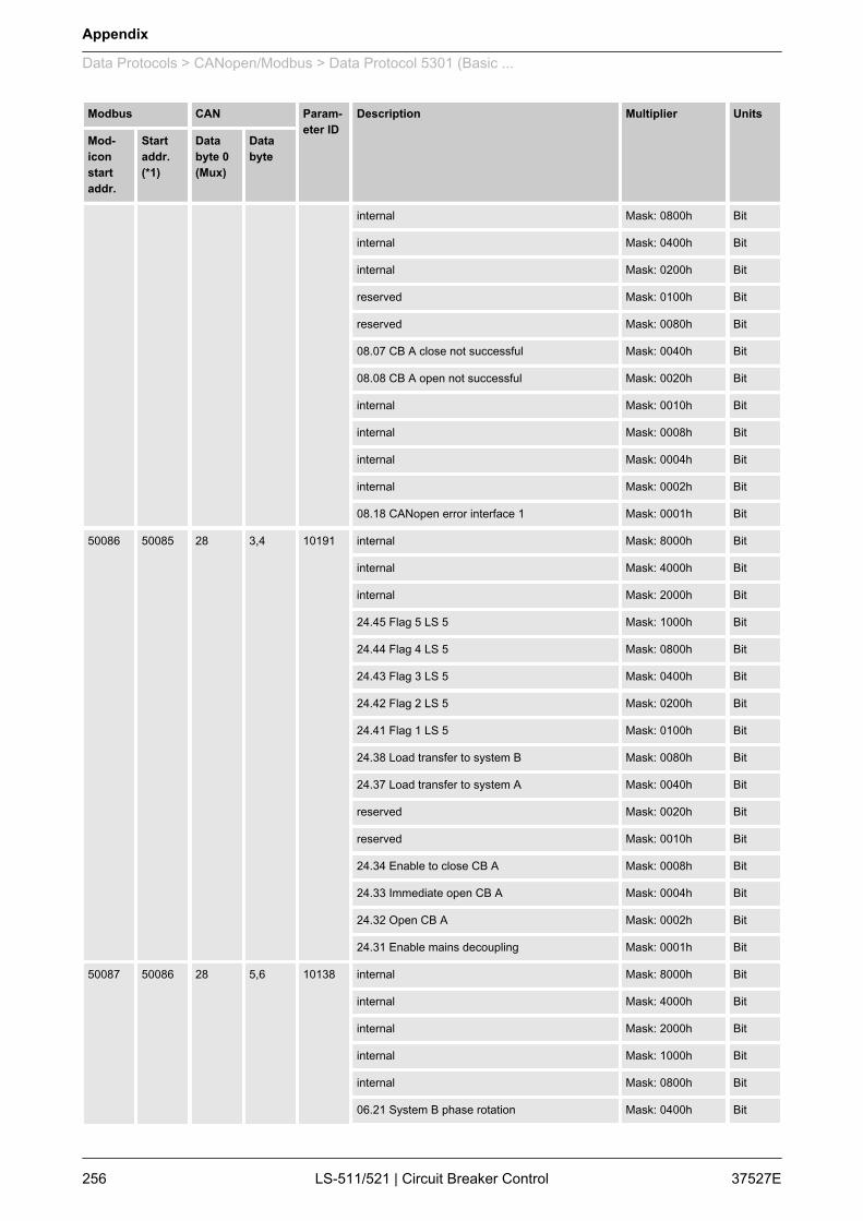
Modbus CAN Param‐eter ID
Description Multiplier Units
Mod‐iconstartaddr.
Startaddr.(*1)
Databyte 0(Mux)
Databyte
internal Mask: 0800h Bit
internal Mask: 0400h Bit
internal Mask: 0200h Bit
reserved Mask: 0100h Bit
reserved Mask: 0080h Bit
08.07 CB A close not successful Mask: 0040h Bit
08.08 CB A open not successful Mask: 0020h Bit
internal Mask: 0010h Bit
internal Mask: 0008h Bit
internal Mask: 0004h Bit
internal Mask: 0002h Bit
08.18 CANopen error interface 1 Mask: 0001h Bit
50086 50085 28 3,4 10191 internal Mask: 8000h Bit
internal Mask: 4000h Bit
internal Mask: 2000h Bit
24.45 Flag 5 LS 5 Mask: 1000h Bit
24.44 Flag 4 LS 5 Mask: 0800h Bit
24.43 Flag 3 LS 5 Mask: 0400h Bit
24.42 Flag 2 LS 5 Mask: 0200h Bit
24.41 Flag 1 LS 5 Mask: 0100h Bit
24.38 Load transfer to system B Mask: 0080h Bit
24.37 Load transfer to system A Mask: 0040h Bit
reserved Mask: 0020h Bit
reserved Mask: 0010h Bit
24.34 Enable to close CB A Mask: 0008h Bit
24.33 Immediate open CB A Mask: 0004h Bit
24.32 Open CB A Mask: 0002h Bit
24.31 Enable mains decoupling Mask: 0001h Bit
50087 50086 28 5,6 10138 internal Mask: 8000h Bit
internal Mask: 4000h Bit
internal Mask: 2000h Bit
internal Mask: 1000h Bit
internal Mask: 0800h Bit
06.21 System B phase rotation Mask: 0400h Bit
Appendix
Data Protocols > CANopen/Modbus > Data Protocol 5301 (Basic ...
37527ELS-511/521 | Circuit Breaker Control256

Modbus CAN Param‐eter ID
Description Multiplier Units
Mod‐iconstartaddr.
Startaddr.(*1)
Databyte 0(Mux)
Databyte
internal Mask: 0200h Bit
internal Mask: 0100h Bit
internal Mask: 0080h Bit
internal Mask: 0040h Bit
internal Mask: 0020h Bit
internal Mask: 0010h Bit
internal Mask: 0008h Bit
internal Mask: 0004h Bit
internal Mask: 0002h Bit
internal Mask: 0001h Bit
50088 50087 29 1,2 10135 07.06 System A overfrequency threshold 1 Mask: 8000h Bit
07.07 System A overfrequency threshold 2 Mask: 4000h Bit
07.08 System A underfrequency threshold 1 Mask: 2000h Bit
07.09 System A underfrequency threshold 2 Mask: 1000h Bit
07.10 System A overvoltage threshold 1 Mask: 0800h Bit
07.11 System A overvoltage threshold 2 Mask: 0400h Bit
07.12 System A undervoltage threshold 1 Mask: 0200h Bit
07.13 System A undervoltage threshold 2 Mask: 0100h Bit
07.14 System A phase shift Mask: 0080h Bit
07.25 System A decoupling Mask: 0040h Bit
internal Mask: 0020h Bit
internal Mask: 0010h Bit
07.26 System A voltage asymmetry (with negativesequence)
Mask: 0008h Bit
07.05 System A phase rotation Mask: 0004h Bit
internal Mask: 0002h Bit
internal Mask: 0001h Bit
50089 50088 29 3,4 4138 internal Mask: 8000h Bit
internal Mask: 4000h Bit
internal Mask: 2000h Bit
internal Mask: 1000h Bit
internal Mask: 0800h Bit
internal Mask: 0400h Bit
internal Mask: 0200h Bit
Appendix
Data Protocols > CANopen/Modbus > Data Protocol 5301 (Basic ...
37527E LS-511/521 | Circuit Breaker Control 257

Modbus CAN Param‐eter ID
Description Multiplier Units
Mod‐iconstartaddr.
Startaddr.(*1)
Databyte 0(Mux)
Databyte
internal Mask: 0100h Bit
07.15 df/dt (ROCOF) Mask: 0080h Bit
internal Mask: 0040h Bit
07.28 System A time-dependent voltage Mask: 0020h Bit
internal Mask: 0010h Bit
07.27 System A voltage increase Mask: 0008h Bit
08.36 CB A unload mismatch Mask: 0004h Bit
07.29 QV Monitoring step 1 tripped Mask: 0002h Bit
07.30 QV Monitoring step 2 tripped Mask: 0001h Bit
50090 50089 29 5,6 - internal Mask: 8000h Bit
internal Mask: 4000h Bit
internal Mask: 2000h Bit
internal Mask: 1000h Bit
internal Mask: 0800h Bit
internal Mask: 0400h Bit
internal Mask: 0200h Bit
internal Mask: 0100h Bit
internal Mask: 0080h Bit
internal Mask: 0040h Bit
internal Mask: 0020h Bit
internal Mask: 0010h Bit
internal Mask: 0008h Bit
internal Mask: 0004h Bit
internal Mask: 0002h Bit
internal Mask: 0001h Bit
9.2.2 CANopen9.2.2.1 Protocol 6003 (LS-5 Communication)
The LS-5 communication message contains all data, which isrequired to operate the LS-5 system. This communication protocolworks parallel to the load share communication.In order to lower the bus load, the messages are divided into "fast","normal", and "slow" refreshed data. The mux is identified accord‐ingly with "F", "N", and "S" (refer to the following tables). The loadshare message contains one fast, two normal, and four slow mes‐sages, which are made up as in Ä “Load share bus communica‐tion” on page 260.
General information
Appendix
Data Protocols > CANopen > Protocol 6003 (LS-5 Commun...
37527ELS-511/521 | Circuit Breaker Control258

The time interval between two fast messages (TFast , i.e. the timefor refreshing a fast message) is configured with the parameter"Transfer rate LS fast message" (parameter 9921 Ä p. 123). Thetime intervals between refreshing a normal or slow messagesdepend on this parameter as well according to the followingsequence:n S0 – F – N0 – F – N1 – F – S1 – F – N0 – F – N1 – F – S2 – F –
N0 – F – N1 – F – S3 – F – N0 – F – N1 – Fn TFast = time interval between refreshing the fast messagen TNormal = time interval between refreshing a normal message =
3 x TFastn TSlow = time interval between refreshing a slow message = 12 x
TFast
n The parameter "Transfer rate LS fast message" (param‐eter 9921 Ä p. 123) is configured to "0.10 s".
n The sequence of the sent messages for TFast = 100 ms (i.e.0.10 s) is shown in Ä “Load share bus communication” on page 260.
n This means that a new message is sent every 50 ms.
Example
Time [ms] 0 50 100 150 200 250 300 350 400 450 500 550
Sent message S0 F N0 F N1 F S1 F N0 F N1 F
Mux # 0 3 1 3 2 3 4 3 1 3 2 3
Time [ms] 600 650 700 750 800 850 900 950 1000 1050 1100 1150
Sent message S2 F N0 F N1 F S3 F N0 F N1 F
Mux # 5 3 1 3 2 3 6 3 1 3 2 3
The maximum length of the CAN bus load share line depends onthis parameter as well. The values in Ä “Load share line - max.length (32 participants)” Table on page 259 are valid for 32 partici‐pants and a bus load of approximately 40 %1.
TFast [ms] TNormal [ms] TSlow [ms] Baud rate[kBaud]
Distance [m]
100 300 1200 250 250
200 600 2400 125 500
300 900 3800 50 1000
Table 41: Load share line - max. length (32 participants)
The maximum length of the CAN bus load share line depends onthis parameter as well. The values in Ä “Load share line - max.length (48 participants)” Table on page 260 are valid for 48 partici‐pants and a bus load of approx. 40 %1.
Timing
CAN bus load share line
Appendix
Data Protocols > CANopen > Protocol 6003 (LS-5 Commun...
37527E LS-511/521 | Circuit Breaker Control 259

TFast [ms] TNormal [ms] TSlow [ms] Baud rate[kBaud]
Distance [m]
100 300 1200 250 250
200 600 2400 125 500
Table 42: Load share line - max. length (48 participants)
1 This approach incorporates two transmit PDO(remote control bits) by a PLC on CAN interface 3 witha refresh time same as the configured TFast - setting inthe easYgen / LS-5.
Parallel to the load share message protocol the easYgen also han‐dles the LS-5 communication protocol.
easYgen LS-5
Load Share Message(protocol 6000)
Transmit / Receive Receive
LS-5 Communication(protocol 6003)
Receive Transmit / Receive
Load share bus communication - "fast" refreshed data
Mux Byte Bit Function Remark
F 0 3 Mux identifier
1 Frequency of connected mains or frequency towhich is to synchronize
Frequency in 00.00 Hz
2
3 Phase angle between system A and B Phase angle [1/10°]
Phase angle compensation is incorpo‐rated
4
5 0 System A in range
1 System B in range
2 System A is black
3 System B is black
4 Breaker 1 closed
5 Isolation switch or breaker 2 closed
6 Synchronous networks detected Between system A an B
7 Not used
6 1 Wish to open the breaker
2 Wish to close the breaker
Correlation of protocols
Load share bus communication
Appendix
Data Protocols > CANopen > Protocol 6003 (LS-5 Commun...
37527ELS-511/521 | Circuit Breaker Control260

Load share bus communication - "fast" refreshed data
Mux Byte Bit Function Remark
3 Wish is for breaker
0 = Breaker 1
1 = Breaker 2
4 Execution of wish
5 Variable system
0 = System A
1 = System B
6 Synchronizing mode
0 = Slip frequency
1 = Phase matching
7 Not used
7 Not used
Load share bus communication - "normal" refreshed data
Mux Byte Bit Function Remark
N0 0 1 Mux identifier
1 Voltage setpoint Voltage of the fixed system in the per‐centage format (000.00 %) of therated voltage setting2
3 Active power system A Long [W]
4
5
6
7 Not used
Load share bus communication - "normal" refreshed data
Mux Byte Bit Function Remark
N1 0 2 Mux identifier
1 Not used
2 0 Logic bit 1
1 Logic bit 2
2 Logic bit 3
3 Logic bit 4
4 Logic bit 5
5 Mains settling active
6-7 Not used
Appendix
Data Protocols > CANopen > Protocol 6003 (LS-5 Commun...
37527E LS-511/521 | Circuit Breaker Control 261
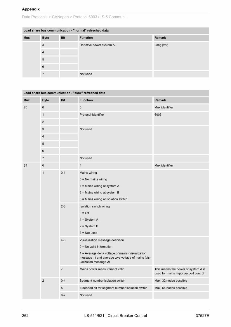
Load share bus communication - "normal" refreshed data
Mux Byte Bit Function Remark
3 Reactive power system A Long [var]
4
5
6
7 Not used
Load share bus communication - "slow" refreshed data
Mux Byte Bit Function Remark
S0 0 0 Mux identifier
1 Protocol-Identifier 6003
2
3 Not used
4
5
6
7 Not used
S1 0 4 Mux identifier
1 0-1 Mains wiring
0 = No mains wiring
1 = Mains wiring at system A
2 = Mains wiring at system B
3 = Mains wiring at isolation switch
2-3 Isolation switch wiring
0 = Off
1 = System A
2 = System B
3 = Not used
4-6 Visualization message definition
0 = No valid information
1 = Average delta voltage of mains (visualizationmessage 1) and average wye voltage of mains (vis‐ualization message 2)
7 Mains power measurement valid This means the power of system A isused for mains import/export control
2 0-4 Segment number isolation switch Max. 32 nodes possible
5 Extended bit for segment number isolation switch Max. 64 nodes possible
6-7 Not used
Appendix
Data Protocols > CANopen > Protocol 6003 (LS-5 Commun...
37527ELS-511/521 | Circuit Breaker Control262

Load share bus communication - "slow" refreshed data
Mux Byte Bit Function Remark
3 Not used
4
5
6
7 Not used
S2 0 5 Mux identifier
1 0-4 Segment number system A 1 to 32
5 Extended bit for segment number system A Max. 64 nodes possible
6-7 Not used
2 0-4 Segment number system B Max. 32 nodes possible
5 Extended bit for segment number system B Max. 64 nodes possible
6-7 Not used
3 Visualization message 1 Dependent on visualization messagedefined in mux "S1"
4
5
6
7 Not used
S3 0 6 Mux identifier
1 Not used
2 Not used
3 Visualization message 2 Dependent of visualization messagedefined in "Slow 1"
4
5
6
7 Not used
9.2.3 Modbus9.2.3.1 Data Protocol 5300 (Basic Visualization)
Modbus Parameter ID Description Multiplier Units
Modiconstartaddr.
Startaddr. (*1)
450001 450000 Protocoll-ID, always 5300 --
450002 450001 3181 Scaling Power (16 bits) Exponent 10x W(5;4;3;2)
Appendix
Data Protocols > Modbus > Data Protocol 5300 (Basic ...
37527E LS-511/521 | Circuit Breaker Control 263

Modbus Parameter ID Description Multiplier Units
Modiconstartaddr.
Startaddr. (*1)
450003 450002 3182 Scaling Volts (16 bits) Exponent 10x V(2;1;0;-1)
450004 450003 3183 Scaling Amps (16 bits) Exponent 10x A (0;-1)
450005 450004 reserved
450006 450005 reserved
450007 450006 reserved
450008 450007 reserved
450009 450008 reserved
AC System A Values
450010 450009 144 System A frequency 0.01 Hz
450011 450010 246 Total system A active power scaled defined byindex 3181 (modiconAdress 450002)
W
450012 450011 247 Total system A reactive power scaled defined byindex 3181 (modiconAdress 450002)
var
450013 450012 160 System A power factor 0.001
450014 450013 248 System A voltage L1-L2 scaled defined byindex 3182 (modiconAdress 450003)
V
450015 450014 249 System A voltage L2-L3 scaled defined byindex 3182 (modiconAdress 450003)
V
450016 450015 250 System A voltage L3-L1 scaled defined byindex 3182 (modiconAdress 450003)
V
450017 450016 251 System A voltage L1-N scaled defined byindex 3182 (modiconAdress 450003)
V
450018 450017 252 System A voltage L2-N scaled defined byindex 3182 (modiconAdress 450003)
V
450019 450018 253 System A voltage L3-N scaled defined byindex 3182 (modiconAdress 450003)
V
450020 450019 255 System A current 1 scaled defined byindex 3183 (modiconAdress 450004)
A
450021 450020 256 System A current 2 scaled defined byindex 3183 (modiconAdress 450004)
A
450022 450021 257 System A current 3 scaled defined byindex 3183 (modiconAdress 450004)
A
Appendix
Data Protocols > Modbus > Data Protocol 5300 (Basic ...
37527ELS-511/521 | Circuit Breaker Control264
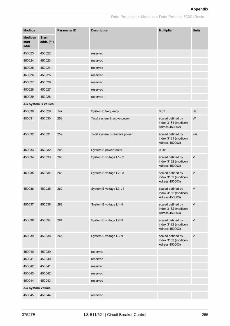
Modbus Parameter ID Description Multiplier Units
Modiconstartaddr.
Startaddr. (*1)
450023 450022 reserved
450024 450023 reserved
450025 450024 reserved
450026 450025 reserved
450027 450026 reserved
450028 450027 reserved
450029 450028 reserved
AC System B Values
450030 450029 147 System B frequency 0.01 Hz
450031 450030 258 Total system B active power scaled defined byindex 3181 (modiconAdress 450002)
W
450032 450031 259 Total system B reactive power scaled defined byindex 3181 (modiconAdress 450002)
var
450033 450032 208 System B power factor 0.001
450034 450033 260 System B voltage L1-L2 scaled defined byindex 3182 (modiconAdress 450003)
V
450035 450034 261 System B voltage L2-L3 scaled defined byindex 3182 (modiconAdress 450003)
V
450036 450035 262 System B voltage L3-L1 scaled defined byindex 3182 (modiconAdress 450003)
V
450037 450036 263 System B voltage L1-N scaled defined byindex 3182 (modiconAdress 450003)
V
450038 450037 264 System B voltage L2-N scaled defined byindex 3182 (modiconAdress 450003)
V
450039 450038 265 System B voltage L3-N scaled defined byindex 3182 (modiconAdress 450003)
V
450040 450039 reserved
450041 450040 reserved
450042 450041 reserved
450043 450042 reserved
450044 450043 reserved
AC System Values
450045 450044 reserved
Appendix
Data Protocols > Modbus > Data Protocol 5300 (Basic ...
37527E LS-511/521 | Circuit Breaker Control 265
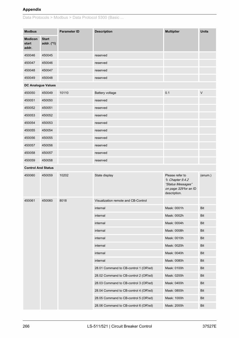
Modbus Parameter ID Description Multiplier Units
Modiconstartaddr.
Startaddr. (*1)
450046 450045 reserved
450047 450046 reserved
450048 450047 reserved
450049 450048 reserved
DC Analogue Values
450050 450049 10110 Battery voltage 0.1 V
450051 450050 reserved
450052 450051 reserved
450053 450052 reserved
450054 450053 reserved
450055 450054 reserved
450056 450055 reserved
450057 450056 reserved
450058 450057 reserved
450059 450058 reserved
Control And Status
450060 450059 10202 State display Please refer toÄ Chapter 9.4.2“Status Messages”on page 329 for an IDdescription.
(enum.)
450061 450060 8018 Visualization remote and CB-Control
internal Mask: 0001h Bit
internal Mask: 0002h Bit
internal Mask: 0004h Bit
internal Mask: 0008h Bit
internal Mask: 0010h Bit
internal Mask: 0020h Bit
internal Mask: 0040h Bit
internal Mask: 0080h Bit
28.01 Command to CB-control 1 (OR'ed) Mask: 0100h Bit
28.02 Command to CB-control 2 (OR'ed) Mask: 0200h Bit
28.03 Command to CB-control 3 (OR'ed) Mask: 0400h Bit
28.04 Command to CB-control 4 (OR'ed) Mask: 0800h Bit
28.05 Command to CB-control 5 (OR'ed) Mask: 1000h Bit
28.06 Command to CB-control 6 (OR'ed) Mask: 2000h Bit
Appendix
Data Protocols > Modbus > Data Protocol 5300 (Basic ...
37527ELS-511/521 | Circuit Breaker Control266

Modbus Parameter ID Description Multiplier Units
Modiconstartaddr.
Startaddr. (*1)
internal Mask: 4000h Bit
internal Mask: 8000h Bit
450062 450061 10146 LogicManagerBits
internal Mask: 0001h Bit
internal Mask: 0002h Bit
internal Mask: 0004h Bit
11.07 Active second Mask: 0008h Bit
11.06 Active minute Mask: 0010h Bit
11.05 Active hour Mask: 0020h Bit
11.04 Active day in month Mask: 0040h Bit
11.03 Active weekday Mask: 0080h Bit
11.02 Time 2 overrun Mask: 0100h Bit
11.01 Time 1 overrun Mask: 0200h Bit
internal Mask: 0400h Bit
04.05 Acknowledge was executed Mask: 0800h Bit
01.09 Shutdown alarms are active (alarm classC-F)
Mask: 1000h Bit
internal Mask: 2000h Bit
internal Mask: 4000h Bit
internal Mask: 8000h Bit
450063 450062 10147 LogicManagerBits1
internal Mask: 0001h Bit
internal Mask: 0002h Bit
internal Mask: 0004h Bit
internal Mask: 0008h Bit
internal Mask: 0010h Bit
internal Mask: 0020h Bit
internal Mask: 0040h Bit
internal Mask: 0080h Bit
internal Mask: 0100h Bit
internal Mask: 0200h Bit
00.46 LM Relay 6 Mask: 0400h Bit
internal Mask: 0800h Bit
00.44 LM Relay 4 Mask: 1000h Bit
00.43 LM Relay 3 Mask: 2000h Bit
Appendix
Data Protocols > Modbus > Data Protocol 5300 (Basic ...
37527E LS-511/521 | Circuit Breaker Control 267
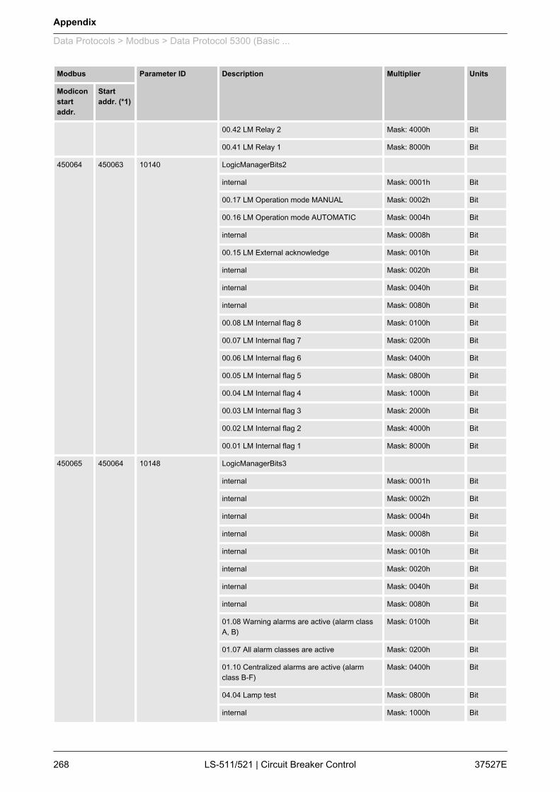
Modbus Parameter ID Description Multiplier Units
Modiconstartaddr.
Startaddr. (*1)
00.42 LM Relay 2 Mask: 4000h Bit
00.41 LM Relay 1 Mask: 8000h Bit
450064 450063 10140 LogicManagerBits2
internal Mask: 0001h Bit
00.17 LM Operation mode MANUAL Mask: 0002h Bit
00.16 LM Operation mode AUTOMATIC Mask: 0004h Bit
internal Mask: 0008h Bit
00.15 LM External acknowledge Mask: 0010h Bit
internal Mask: 0020h Bit
internal Mask: 0040h Bit
internal Mask: 0080h Bit
00.08 LM Internal flag 8 Mask: 0100h Bit
00.07 LM Internal flag 7 Mask: 0200h Bit
00.06 LM Internal flag 6 Mask: 0400h Bit
00.05 LM Internal flag 5 Mask: 0800h Bit
00.04 LM Internal flag 4 Mask: 1000h Bit
00.03 LM Internal flag 3 Mask: 2000h Bit
00.02 LM Internal flag 2 Mask: 4000h Bit
00.01 LM Internal flag 1 Mask: 8000h Bit
450065 450064 10148 LogicManagerBits3
internal Mask: 0001h Bit
internal Mask: 0002h Bit
internal Mask: 0004h Bit
internal Mask: 0008h Bit
internal Mask: 0010h Bit
internal Mask: 0020h Bit
internal Mask: 0040h Bit
internal Mask: 0080h Bit
01.08 Warning alarms are active (alarm classA, B)
Mask: 0100h Bit
01.07 All alarm classes are active Mask: 0200h Bit
01.10 Centralized alarms are active (alarmclass B-F)
Mask: 0400h Bit
04.04 Lamp test Mask: 0800h Bit
internal Mask: 1000h Bit
Appendix
Data Protocols > Modbus > Data Protocol 5300 (Basic ...
37527ELS-511/521 | Circuit Breaker Control268

Modbus Parameter ID Description Multiplier Units
Modiconstartaddr.
Startaddr. (*1)
internal Mask: 2000h Bit
internal Mask: 4000h Bit
internal Mask: 8000h Bit
450066 450065 10150 LogicManagerBits4
internal Mask: 0001h Bit
internal Mask: 0002h Bit
00.37 LM Internal flag 16 Mask: 0004h Bit
00.36 LM Internal flag 15 Mask: 0008h Bit
00.35 LM Internal flag 14 Mask: 0010h Bit
00.34 LM Internal flag 13 Mask: 0020h Bit
00.33 LM Internal flag 12 Mask: 0040h Bit
00.32 LM Internal flag 11 Mask: 0080h Bit
00.31 LM Internal flag 10 Mask: 0100h Bit
00.30 LM Internal flag 9 Mask: 0200h Bit
internal Mask: 0400h Bit
internal Mask: 0800h Bit
internal Mask: 1000h Bit
internal Mask: 2000h Bit
internal Mask: 4000h Bit
internal Mask: 8000h Bit
450067 450066 10162 LogicManagerBits6
00.40 LM Synchronization mode RUN Mask: 0001h Bit
00.39 LM Synchronization mode PERMISSIVE Mask: 0002h Bit
00.38 LM Synchronization mode CHECK Mask: 0004h Bit
internal Mask: 0008h Bit
internal Mask: 0010h Bit
internal Mask: 0020h Bit
internal Mask: 0040h Bit
internal Mask: 0080h Bit
internal Mask: 0100h Bit
internal Mask: 0200h Bit
internal Mask: 0400h Bit
internal Mask: 0800h Bit
internal Mask: 1000h Bit
internal Mask: 2000h Bit
Appendix
Data Protocols > Modbus > Data Protocol 5300 (Basic ...
37527E LS-511/521 | Circuit Breaker Control 269
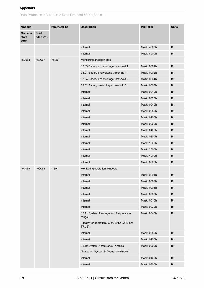
Modbus Parameter ID Description Multiplier Units
Modiconstartaddr.
Startaddr. (*1)
internal Mask: 4000h Bit
internal Mask: 8000h Bit
450068 450067 10136 Monitoring analog inputs
08.03 Battery undervoltage threshold 1 Mask: 0001h Bit
08.01 Battery overvoltage threshold 1 Mask: 0002h Bit
08.04 Battery undervoltage threshold 2 Mask: 0004h Bit
08.02 Battery overvoltage threshold 2 Mask: 0008h Bit
internal Mask: 0010h Bit
internal Mask: 0020h Bit
internal Mask: 0040h Bit
internal Mask: 0080h Bit
internal Mask: 0100h Bit
internal Mask: 0200h Bit
internal Mask: 0400h Bit
internal Mask: 0800h Bit
internal Mask: 1000h Bit
internal Mask: 2000h Bit
internal Mask: 4000h Bit
internal Mask: 8000h Bit
450069 450068 4139 Monitoring operation windows
internal Mask: 0001h Bit
internal Mask: 0002h Bit
internal Mask: 0004h Bit
internal Mask: 0008h Bit
internal Mask: 0010h Bit
internal Mask: 0020h Bit
02.11 System A voltage and frequency inrange
(Ready for operation, 02.09 AND 02.10 areTRUE)
Mask: 0040h Bit
internal Mask: 0080h Bit
internal Mask: 0100h Bit
02.10 System A frequency in range
(Based on System B frequency window)
Mask: 0200h Bit
internal Mask: 0400h Bit
internal Mask: 0800h Bit
Appendix
Data Protocols > Modbus > Data Protocol 5300 (Basic ...
37527ELS-511/521 | Circuit Breaker Control270
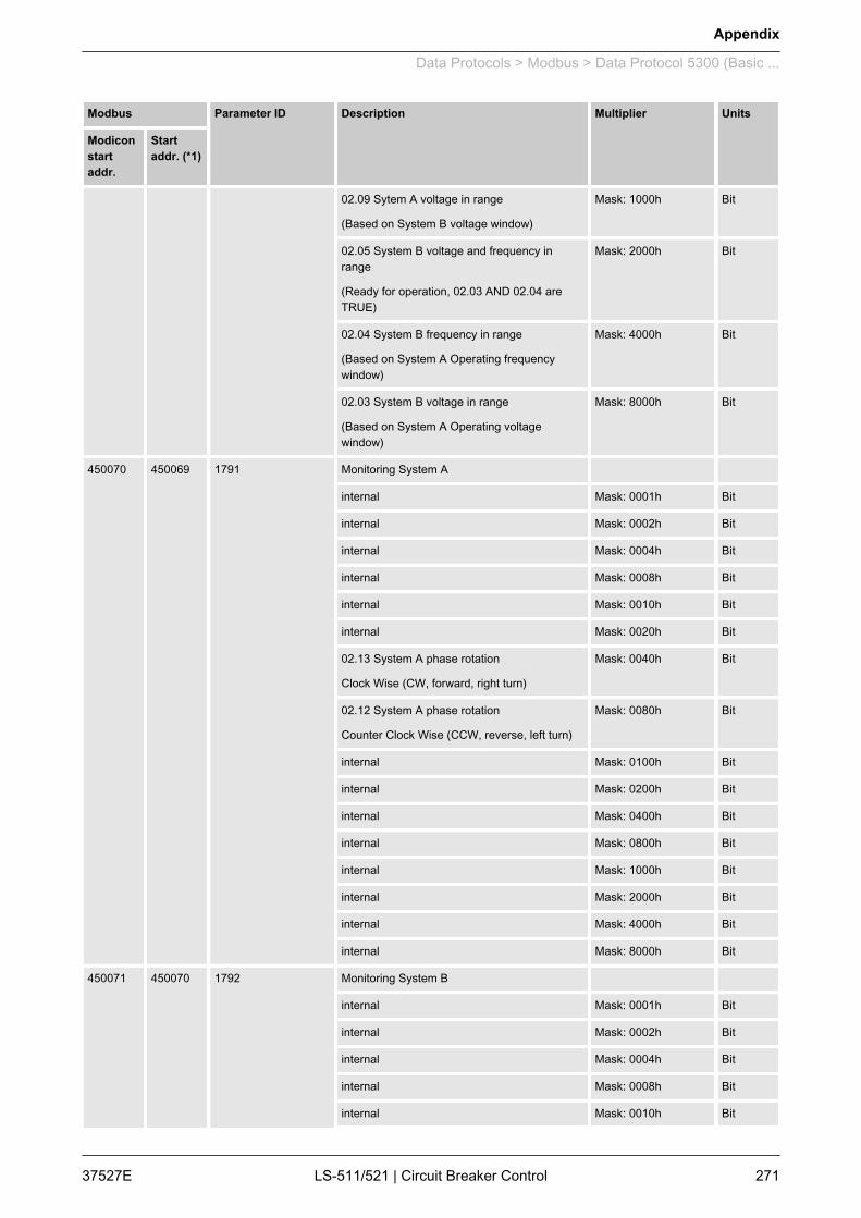
Modbus Parameter ID Description Multiplier Units
Modiconstartaddr.
Startaddr. (*1)
02.09 Sytem A voltage in range
(Based on System B voltage window)
Mask: 1000h Bit
02.05 System B voltage and frequency inrange
(Ready for operation, 02.03 AND 02.04 areTRUE)
Mask: 2000h Bit
02.04 System B frequency in range
(Based on System A Operating frequencywindow)
Mask: 4000h Bit
02.03 System B voltage in range
(Based on System A Operating voltagewindow)
Mask: 8000h Bit
450070 450069 1791 Monitoring System A
internal Mask: 0001h Bit
internal Mask: 0002h Bit
internal Mask: 0004h Bit
internal Mask: 0008h Bit
internal Mask: 0010h Bit
internal Mask: 0020h Bit
02.13 System A phase rotation
Clock Wise (CW, forward, right turn)
Mask: 0040h Bit
02.12 System A phase rotation
Counter Clock Wise (CCW, reverse, left turn)
Mask: 0080h Bit
internal Mask: 0100h Bit
internal Mask: 0200h Bit
internal Mask: 0400h Bit
internal Mask: 0800h Bit
internal Mask: 1000h Bit
internal Mask: 2000h Bit
internal Mask: 4000h Bit
internal Mask: 8000h Bit
450071 450070 1792 Monitoring System B
internal Mask: 0001h Bit
internal Mask: 0002h Bit
internal Mask: 0004h Bit
internal Mask: 0008h Bit
internal Mask: 0010h Bit
Appendix
Data Protocols > Modbus > Data Protocol 5300 (Basic ...
37527E LS-511/521 | Circuit Breaker Control 271

Modbus Parameter ID Description Multiplier Units
Modiconstartaddr.
Startaddr. (*1)
internal Mask: 0020h Bit
02.15 System B phase rotation
Clock Wise (CW, forward, right turn)
Mask: 0040h Bit
02.14 System B phase rotation
Counter Clock Wise (CCW, reverse, left turn)
Mask: 0080h Bit
internal Mask: 0100h Bit
internal Mask: 0200h Bit
internal Mask: 0400h Bit
internal Mask: 0800h Bit
internal Mask: 1000h Bit
internal Mask: 2000h Bit
internal Mask: 4000h Bit
internal Mask: 8000h Bit
450072 450071 reserved
450073 450072 4153 ControlBits1
04.01 Operating mode AUTOMATIC Mask: 0001h Bit
04.03 Operating mode MANUAL Mask: 0002h Bit
04.04 Lamp test request Mask: 0004h Bit
04.07 CB A is closed Mask: 0008h Bit
24.39 Isolation switch is open Mask: 0010h Bit
04.11 Mains settling is active Mask: 0020h Bit
reserved Mask: 0040h Bit
reserved Mask: 0080h Bit
reserved Mask: 0100h Bit
04.21 Synchronization CB A procedure isactive
Mask: 0200h Bit
04.22 Open command CB A is active Mask: 0400h Bit
04.23 Close command CB A is active Mask: 0800h Bit
reserved Mask: 1000h Bit
04.29 Unloading CB A is active Mask: 2000h Bit
reserved Mask: 4000h Bit
reserved Mask: 8000h Bit
450074 450073 4154 ControlBits2
internal Mask: 0001h Bit
04.62 Dead bus closure procedure is active Mask: 0002h Bit
Appendix
Data Protocols > Modbus > Data Protocol 5300 (Basic ...
37527ELS-511/521 | Circuit Breaker Control272
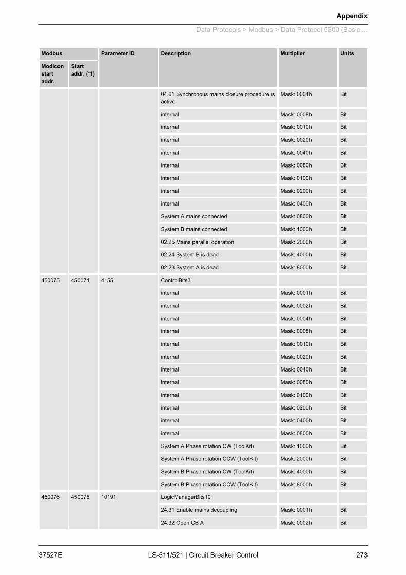
Modbus Parameter ID Description Multiplier Units
Modiconstartaddr.
Startaddr. (*1)
04.61 Synchronous mains closure procedure isactive
Mask: 0004h Bit
internal Mask: 0008h Bit
internal Mask: 0010h Bit
internal Mask: 0020h Bit
internal Mask: 0040h Bit
internal Mask: 0080h Bit
internal Mask: 0100h Bit
internal Mask: 0200h Bit
internal Mask: 0400h Bit
System A mains connected Mask: 0800h Bit
System B mains connected Mask: 1000h Bit
02.25 Mains parallel operation Mask: 2000h Bit
02.24 System B is dead Mask: 4000h Bit
02.23 System A is dead Mask: 8000h Bit
450075 450074 4155 ControlBits3
internal Mask: 0001h Bit
internal Mask: 0002h Bit
internal Mask: 0004h Bit
internal Mask: 0008h Bit
internal Mask: 0010h Bit
internal Mask: 0020h Bit
internal Mask: 0040h Bit
internal Mask: 0080h Bit
internal Mask: 0100h Bit
internal Mask: 0200h Bit
internal Mask: 0400h Bit
internal Mask: 0800h Bit
System A Phase rotation CW (ToolKit) Mask: 1000h Bit
System A Phase rotation CCW (ToolKit) Mask: 2000h Bit
System B Phase rotation CW (ToolKit) Mask: 4000h Bit
System B Phase rotation CCW (ToolKit) Mask: 8000h Bit
450076 450075 10191 LogicManagerBits10
24.31 Enable mains decoupling Mask: 0001h Bit
24.32 Open CB A Mask: 0002h Bit
Appendix
Data Protocols > Modbus > Data Protocol 5300 (Basic ...
37527E LS-511/521 | Circuit Breaker Control 273

Modbus Parameter ID Description Multiplier Units
Modiconstartaddr.
Startaddr. (*1)
24.33 Immediate open CB A Mask: 0004h Bit
24.34 Enable to close CB A Mask: 0008h Bit
internal Mask: 0010h Bit
internal Mask: 0020h Bit
24.37 Load transfer to system A Mask: 0040h Bit
24.38 Load transfer to system B Mask: 0080h Bit
24.41 Flag 1 LS 5 Mask: 0100h Bit
24.42 Flag 2 LS 5 Mask: 0200h Bit
24.43 Flag 3 LS 5 Mask: 0400h Bit
24.44 Flag 4 LS 5 Mask: 0800h Bit
24.45 Flag 5 LS 5 Mask: 1000h Bit
internal Mask: 2000h Bit
internal Mask: 4000h Bit
internal Mask: 8000h Bit
450077 450076 10138 Monitoring System B
internal Mask: 0001h Bit
internal Mask: 0002h Bit
internal Mask: 0004h Bit
internal Mask: 0008h Bit
internal Mask: 0010h Bit
internal Mask: 0020h Bit
internal Mask: 0040h Bit
internal Mask: 0080h Bit
internal Mask: 0100h Bit
internal Mask: 0200h Bit
06.21 System B phase rotation Mask: 0400h Bit
internal Mask: 0800h Bit
internal Mask: 1000h Bit
internal Mask: 2000h Bit
internal Mask: 4000h Bit
internal Mask: 8000h Bit
450078 450077 10135 Monitoring System A
internal Mask: 0001h Bit
internal Mask: 0002h Bit
07.05 System A phase rotation Mask: 0004h Bit
Appendix
Data Protocols > Modbus > Data Protocol 5300 (Basic ...
37527ELS-511/521 | Circuit Breaker Control274
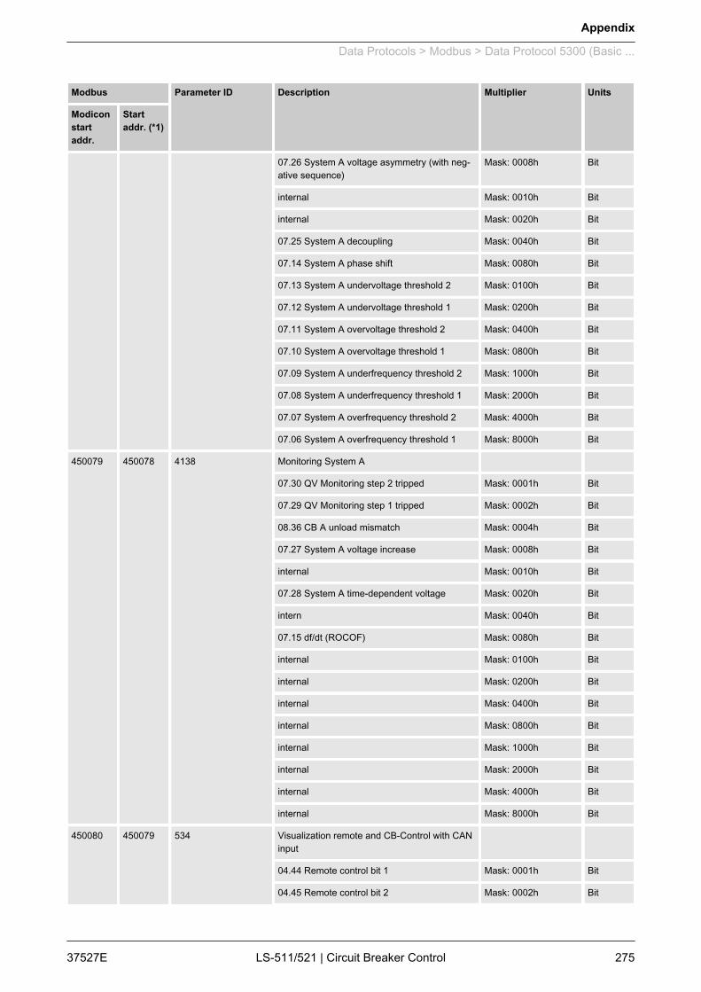
Modbus Parameter ID Description Multiplier Units
Modiconstartaddr.
Startaddr. (*1)
07.26 System A voltage asymmetry (with neg‐ative sequence)
Mask: 0008h Bit
internal Mask: 0010h Bit
internal Mask: 0020h Bit
07.25 System A decoupling Mask: 0040h Bit
07.14 System A phase shift Mask: 0080h Bit
07.13 System A undervoltage threshold 2 Mask: 0100h Bit
07.12 System A undervoltage threshold 1 Mask: 0200h Bit
07.11 System A overvoltage threshold 2 Mask: 0400h Bit
07.10 System A overvoltage threshold 1 Mask: 0800h Bit
07.09 System A underfrequency threshold 2 Mask: 1000h Bit
07.08 System A underfrequency threshold 1 Mask: 2000h Bit
07.07 System A overfrequency threshold 2 Mask: 4000h Bit
07.06 System A overfrequency threshold 1 Mask: 8000h Bit
450079 450078 4138 Monitoring System A
07.30 QV Monitoring step 2 tripped Mask: 0001h Bit
07.29 QV Monitoring step 1 tripped Mask: 0002h Bit
08.36 CB A unload mismatch Mask: 0004h Bit
07.27 System A voltage increase Mask: 0008h Bit
internal Mask: 0010h Bit
07.28 System A time-dependent voltage Mask: 0020h Bit
intern Mask: 0040h Bit
07.15 df/dt (ROCOF) Mask: 0080h Bit
internal Mask: 0100h Bit
internal Mask: 0200h Bit
internal Mask: 0400h Bit
internal Mask: 0800h Bit
internal Mask: 1000h Bit
internal Mask: 2000h Bit
internal Mask: 4000h Bit
internal Mask: 8000h Bit
450080 450079 534 Visualization remote and CB-Control with CANinput
04.44 Remote control bit 1 Mask: 0001h Bit
04.45 Remote control bit 2 Mask: 0002h Bit
Appendix
Data Protocols > Modbus > Data Protocol 5300 (Basic ...
37527E LS-511/521 | Circuit Breaker Control 275
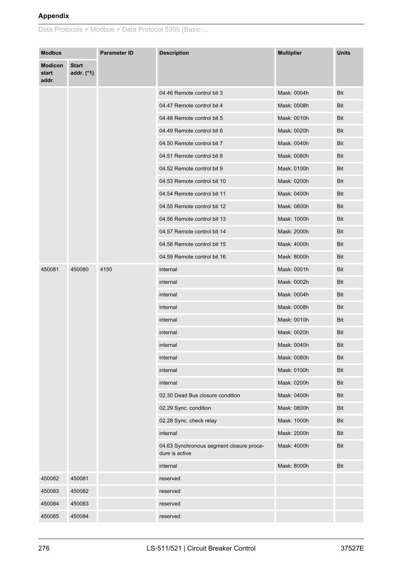
Modbus Parameter ID Description Multiplier Units
Modiconstartaddr.
Startaddr. (*1)
04.46 Remote control bit 3 Mask: 0004h Bit
04.47 Remote control bit 4 Mask: 0008h Bit
04.48 Remote control bit 5 Mask: 0010h Bit
04.49 Remote control bit 6 Mask: 0020h Bit
04.50 Remote control bit 7 Mask: 0040h Bit
04.51 Remote control bit 8 Mask: 0080h Bit
04.52 Remote control bit 9 Mask: 0100h Bit
04.53 Remote control bit 10 Mask: 0200h Bit
04.54 Remote control bit 11 Mask: 0400h Bit
04.55 Remote control bit 12 Mask: 0800h Bit
04.56 Remote control bit 13 Mask: 1000h Bit
04.57 Remote control bit 14 Mask: 2000h Bit
04.58 Remote control bit 15 Mask: 4000h Bit
04.59 Remote control bit 16 Mask: 8000h Bit
450081 450080 4150 internal Mask: 0001h Bit
internal Mask: 0002h Bit
internal Mask: 0004h Bit
internal Mask: 0008h Bit
internal Mask: 0010h Bit
internal Mask: 0020h Bit
internal Mask: 0040h Bit
internal Mask: 0080h Bit
internal Mask: 0100h Bit
internal Mask: 0200h Bit
02.30 Dead Bus closure condition Mask: 0400h Bit
02.29 Sync. condition Mask: 0800h Bit
02.28 Sync. check relay Mask: 1000h Bit
internal Mask: 2000h Bit
04.63 Synchronous segment closure proce‐dure is active
Mask: 4000h Bit
internal Mask: 8000h Bit
450082 450081 reserved
450083 450082 reserved
450084 450083 reserved
450085 450084 reserved
Appendix
Data Protocols > Modbus > Data Protocol 5300 (Basic ...
37527ELS-511/521 | Circuit Breaker Control276
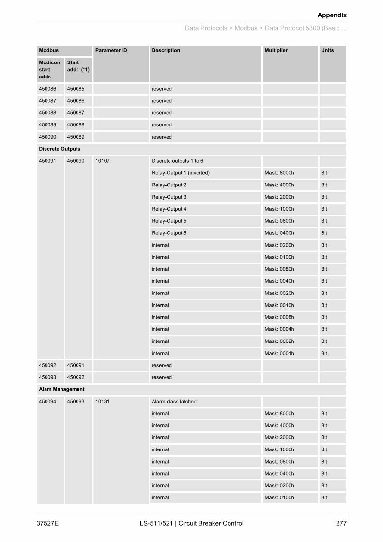
Modbus Parameter ID Description Multiplier Units
Modiconstartaddr.
Startaddr. (*1)
450086 450085 reserved
450087 450086 reserved
450088 450087 reserved
450089 450088 reserved
450090 450089 reserved
Discrete Outputs
450091 450090 10107 Discrete outputs 1 to 6
Relay-Output 1 (inverted) Mask: 8000h Bit
Relay-Output 2 Mask: 4000h Bit
Relay-Output 3 Mask: 2000h Bit
Relay-Output 4 Mask: 1000h Bit
Relay-Output 5 Mask: 0800h Bit
Relay-Output 6 Mask: 0400h Bit
internal Mask: 0200h Bit
internal Mask: 0100h Bit
internal Mask: 0080h Bit
internal Mask: 0040h Bit
internal Mask: 0020h Bit
internal Mask: 0010h Bit
internal Mask: 0008h Bit
internal Mask: 0004h Bit
internal Mask: 0002h Bit
internal Mask: 0001h Bit
450092 450091 reserved
450093 450092 reserved
Alam Management
450094 450093 10131 Alarm class latched
internal Mask: 8000h Bit
internal Mask: 4000h Bit
internal Mask: 2000h Bit
internal Mask: 1000h Bit
internal Mask: 0800h Bit
internal Mask: 0400h Bit
internal Mask: 0200h Bit
internal Mask: 0100h Bit
Appendix
Data Protocols > Modbus > Data Protocol 5300 (Basic ...
37527E LS-511/521 | Circuit Breaker Control 277

Modbus Parameter ID Description Multiplier Units
Modiconstartaddr.
Startaddr. (*1)
internal Mask: 0080h Bit
internal Mask: 0040h Bit
Alarm class F latched Mask: 0020h Bit
Alarm class E latched Mask: 0010h Bit
Alarm class D latched Mask: 0008h Bit
Alarm class C latched Mask: 0004h Bit
Alarm class B latched Mask: 0002h Bit
Alarm class A latched Mask: 0001h Bit
450095 450094 10160 LogicManagerBits5
internal Mask: 8000h Bit
internal Mask: 4000h Bit
internal Mask: 2000h Bit
internal Mask: 1000h Bit
internal Mask: 0800h Bit
internal Mask: 0400h Bit
internal Mask: 0200h Bit
internal Mask: 0100h Bit
internal Mask: 0080h Bit
internal Mask: 0040h Bit
internal Mask: 0020h Bit
internal Mask: 0010h Bit
internal Mask: 0008h Bit
internal Mask: 0004h Bit
01.11 New alarm triggered Mask: 0002h Bit
internal Mask: 0001h Bit
450096 450095 10149 Alarm2
reserved Mask: 8000h Bit
08.31 Timeout synchronization CB A Mask: 4000h Bit
internal Mask: 2000h Bit
internal Mask: 1000h Bit
08.33 System A / System B phase rotationmismatch
Mask: 0800h Bit
reserved Mask: 0400h Bit
internal Mask: 0200h Bit
internal Mask: 0100h Bit
Appendix
Data Protocols > Modbus > Data Protocol 5300 (Basic ...
37527ELS-511/521 | Circuit Breaker Control278
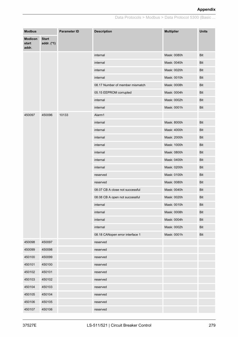
Modbus Parameter ID Description Multiplier Units
Modiconstartaddr.
Startaddr. (*1)
internal Mask: 0080h Bit
internal Mask: 0040h Bit
internal Mask: 0020h Bit
internal Mask: 0010h Bit
08.17 Number of member mismatch Mask: 0008h Bit
05.15 EEPROM corrupted Mask: 0004h Bit
internal Mask: 0002h Bit
internal Mask: 0001h Bit
450097 450096 10133 Alarm1
internal Mask: 8000h Bit
internal Mask: 4000h Bit
internal Mask: 2000h Bit
internal Mask: 1000h Bit
internal Mask: 0800h Bit
internal Mask: 0400h Bit
internal Mask: 0200h Bit
reserved Mask: 0100h Bit
reserved Mask: 0080h Bit
08.07 CB A close not successful Mask: 0040h Bit
08.08 CB A open not successful Mask: 0020h Bit
internal Mask: 0010h Bit
internal Mask: 0008h Bit
internal Mask: 0004h Bit
internal Mask: 0002h Bit
08.18 CANopen error interface 1 Mask: 0001h Bit
450098 450097 reserved
450099 450098 reserved
450100 450099 reserved
450101 450100 reserved
450102 450101 reserved
450103 450102 reserved
450104 450103 reserved
450105 450104 reserved
450106 450105 reserved
450107 450106 reserved
Appendix
Data Protocols > Modbus > Data Protocol 5300 (Basic ...
37527E LS-511/521 | Circuit Breaker Control 279

Modbus Parameter ID Description Multiplier Units
Modiconstartaddr.
Startaddr. (*1)
450108 450107 reserved
System A
450109 450108 reserved
450110 450109 reserved
System B
450111 450110 reserved
450112 450111 reserved
Discrete Inputs
450113 450112 10132 Alarms discrete inputs 1 latched (unacknowl‐edged)
10608 State Discrete Input 8 Mask: 8000h Bit
10607 State Discrete Input 7 Mask: 4000h Bit
10605 State Discrete Input 6 Mask: 2000h Bit
10604 State Discrete Input 5 Mask: 1000h Bit
10603 State Discrete Input 4 Mask: 0800h Bit
10602 State Discrete Input 3 Mask: 0400h Bit
10601 State Discrete Input 2 Mask: 0200h Bit
10600 State Discrete Input 1 Mask: 0100h Bit
internal Mask: 0080h Bit
internal Mask: 0040h Bit
internal Mask: 0020h Bit
internal Mask: 0010h Bit
internal Mask: 0008h Bit
internal Mask: 0004h Bit
internal Mask: 0002h Bit
internal Mask: 0001h Bit
450114 450113 reserved
450115 450114 reserved
450116 450115 reserved
450117 450116 reserved
DC Analogue Values Wirebreak
450118 450117 10137 Alarms analog inputs wire break latched (unac‐knowledged)
internal Mask: 0001h Bit
internal Mask: 0002h Bit
Appendix
Data Protocols > Modbus > Data Protocol 5300 (Basic ...
37527ELS-511/521 | Circuit Breaker Control280

Modbus Parameter ID Description Multiplier Units
Modiconstartaddr.
Startaddr. (*1)
internal Mask: 0004h Bit
internal Mask: 0008h Bit
internal Mask: 0010h Bit
internal Mask: 0020h Bit
internal Mask: 0040h Bit
internal Mask: 0080h Bit
internal Mask: 0100h Bit
internal Mask: 0200h Bit
internal Mask: 0400h Bit
internal Mask: 0800h Bit
internal Mask: 1000h Bit
internal Mask: 2000h Bit
internal Mask: 4000h Bit
internal Mask: 8000h Bit
450119 450118 reserved
450120 450119 reserved
easYgen-3000 Controls
450121 450120 Status of Device 1
Generator voltage and frequency ok Mask: 0001h Bit
Busbar voltage and frequency ok Mask: 0002h Bit
Mains voltage and frequency ok Mask: 0004h Bit
4th system voltage and frequency ok Mask: 0008h Bit
Busbar 1 dead busbar detection Mask: 0010h Bit
Busbar 2 dead busbar detection Mask: 0020h Bit
internal Mask: 0040h Bit
internal Mask: 0080h Bit
29.01 Command to CB-control 1 Mask: 0100h Bit
29.02 Command to CB-control 2 Mask: 0200h Bit
29.03 Command to CB-control 3 Mask: 0400h Bit
29.04 Command to CB-control 4 Mask: 0800h Bit
29.05 Command to CB-control 5 Mask: 1000h Bit
29.06 Command to CB-control 6 Mask: 2000h Bit
internal Mask: 4000h Bit
internal Mask: 8000h Bit
450122 450121 Status of Device 2
Appendix
Data Protocols > Modbus > Data Protocol 5300 (Basic ...
37527E LS-511/521 | Circuit Breaker Control 281
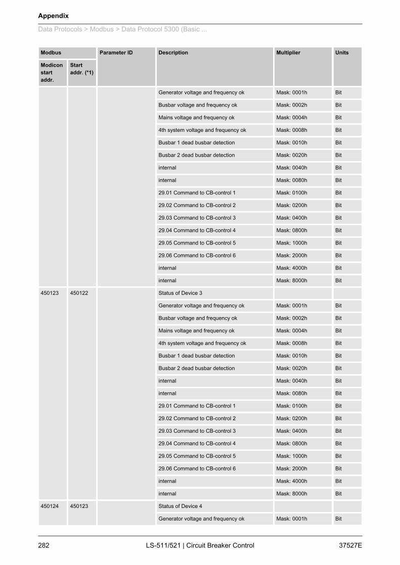
Modbus Parameter ID Description Multiplier Units
Modiconstartaddr.
Startaddr. (*1)
Generator voltage and frequency ok Mask: 0001h Bit
Busbar voltage and frequency ok Mask: 0002h Bit
Mains voltage and frequency ok Mask: 0004h Bit
4th system voltage and frequency ok Mask: 0008h Bit
Busbar 1 dead busbar detection Mask: 0010h Bit
Busbar 2 dead busbar detection Mask: 0020h Bit
internal Mask: 0040h Bit
internal Mask: 0080h Bit
29.01 Command to CB-control 1 Mask: 0100h Bit
29.02 Command to CB-control 2 Mask: 0200h Bit
29.03 Command to CB-control 3 Mask: 0400h Bit
29.04 Command to CB-control 4 Mask: 0800h Bit
29.05 Command to CB-control 5 Mask: 1000h Bit
29.06 Command to CB-control 6 Mask: 2000h Bit
internal Mask: 4000h Bit
internal Mask: 8000h Bit
450123 450122 Status of Device 3
Generator voltage and frequency ok Mask: 0001h Bit
Busbar voltage and frequency ok Mask: 0002h Bit
Mains voltage and frequency ok Mask: 0004h Bit
4th system voltage and frequency ok Mask: 0008h Bit
Busbar 1 dead busbar detection Mask: 0010h Bit
Busbar 2 dead busbar detection Mask: 0020h Bit
internal Mask: 0040h Bit
internal Mask: 0080h Bit
29.01 Command to CB-control 1 Mask: 0100h Bit
29.02 Command to CB-control 2 Mask: 0200h Bit
29.03 Command to CB-control 3 Mask: 0400h Bit
29.04 Command to CB-control 4 Mask: 0800h Bit
29.05 Command to CB-control 5 Mask: 1000h Bit
29.06 Command to CB-control 6 Mask: 2000h Bit
internal Mask: 4000h Bit
internal Mask: 8000h Bit
450124 450123 Status of Device 4
Generator voltage and frequency ok Mask: 0001h Bit
Appendix
Data Protocols > Modbus > Data Protocol 5300 (Basic ...
37527ELS-511/521 | Circuit Breaker Control282
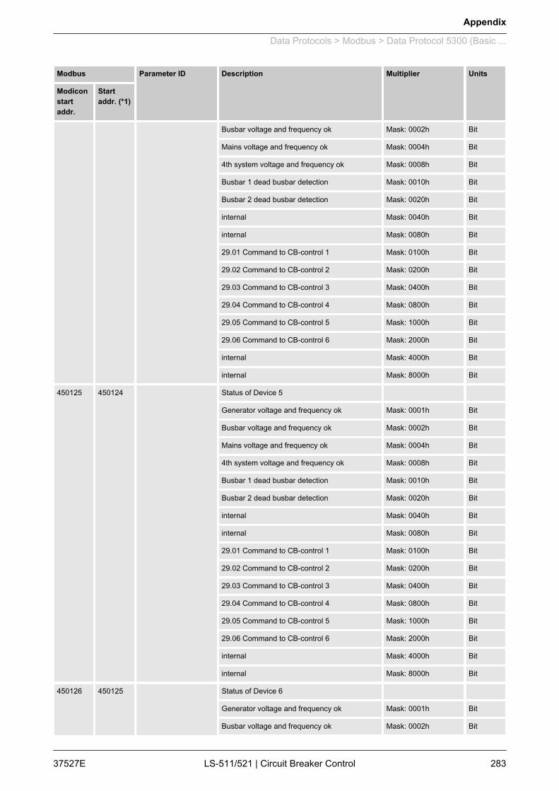
Modbus Parameter ID Description Multiplier Units
Modiconstartaddr.
Startaddr. (*1)
Busbar voltage and frequency ok Mask: 0002h Bit
Mains voltage and frequency ok Mask: 0004h Bit
4th system voltage and frequency ok Mask: 0008h Bit
Busbar 1 dead busbar detection Mask: 0010h Bit
Busbar 2 dead busbar detection Mask: 0020h Bit
internal Mask: 0040h Bit
internal Mask: 0080h Bit
29.01 Command to CB-control 1 Mask: 0100h Bit
29.02 Command to CB-control 2 Mask: 0200h Bit
29.03 Command to CB-control 3 Mask: 0400h Bit
29.04 Command to CB-control 4 Mask: 0800h Bit
29.05 Command to CB-control 5 Mask: 1000h Bit
29.06 Command to CB-control 6 Mask: 2000h Bit
internal Mask: 4000h Bit
internal Mask: 8000h Bit
450125 450124 Status of Device 5
Generator voltage and frequency ok Mask: 0001h Bit
Busbar voltage and frequency ok Mask: 0002h Bit
Mains voltage and frequency ok Mask: 0004h Bit
4th system voltage and frequency ok Mask: 0008h Bit
Busbar 1 dead busbar detection Mask: 0010h Bit
Busbar 2 dead busbar detection Mask: 0020h Bit
internal Mask: 0040h Bit
internal Mask: 0080h Bit
29.01 Command to CB-control 1 Mask: 0100h Bit
29.02 Command to CB-control 2 Mask: 0200h Bit
29.03 Command to CB-control 3 Mask: 0400h Bit
29.04 Command to CB-control 4 Mask: 0800h Bit
29.05 Command to CB-control 5 Mask: 1000h Bit
29.06 Command to CB-control 6 Mask: 2000h Bit
internal Mask: 4000h Bit
internal Mask: 8000h Bit
450126 450125 Status of Device 6
Generator voltage and frequency ok Mask: 0001h Bit
Busbar voltage and frequency ok Mask: 0002h Bit
Appendix
Data Protocols > Modbus > Data Protocol 5300 (Basic ...
37527E LS-511/521 | Circuit Breaker Control 283
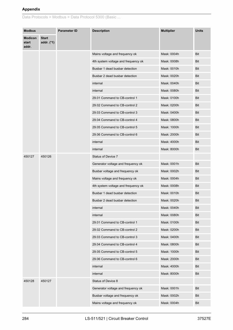
Modbus Parameter ID Description Multiplier Units
Modiconstartaddr.
Startaddr. (*1)
Mains voltage and frequency ok Mask: 0004h Bit
4th system voltage and frequency ok Mask: 0008h Bit
Busbar 1 dead busbar detection Mask: 0010h Bit
Busbar 2 dead busbar detection Mask: 0020h Bit
internal Mask: 0040h Bit
internal Mask: 0080h Bit
29.01 Command to CB-control 1 Mask: 0100h Bit
29.02 Command to CB-control 2 Mask: 0200h Bit
29.03 Command to CB-control 3 Mask: 0400h Bit
29.04 Command to CB-control 4 Mask: 0800h Bit
29.05 Command to CB-control 5 Mask: 1000h Bit
29.06 Command to CB-control 6 Mask: 2000h Bit
internal Mask: 4000h Bit
internal Mask: 8000h Bit
450127 450126 Status of Device 7
Generator voltage and frequency ok Mask: 0001h Bit
Busbar voltage and frequency ok Mask: 0002h Bit
Mains voltage and frequency ok Mask: 0004h Bit
4th system voltage and frequency ok Mask: 0008h Bit
Busbar 1 dead busbar detection Mask: 0010h Bit
Busbar 2 dead busbar detection Mask: 0020h Bit
internal Mask: 0040h Bit
internal Mask: 0080h Bit
29.01 Command to CB-control 1 Mask: 0100h Bit
29.02 Command to CB-control 2 Mask: 0200h Bit
29.03 Command to CB-control 3 Mask: 0400h Bit
29.04 Command to CB-control 4 Mask: 0800h Bit
29.05 Command to CB-control 5 Mask: 1000h Bit
29.06 Command to CB-control 6 Mask: 2000h Bit
internal Mask: 4000h Bit
internal Mask: 8000h Bit
450128 450127 Status of Device 8
Generator voltage and frequency ok Mask: 0001h Bit
Busbar voltage and frequency ok Mask: 0002h Bit
Mains voltage and frequency ok Mask: 0004h Bit
Appendix
Data Protocols > Modbus > Data Protocol 5300 (Basic ...
37527ELS-511/521 | Circuit Breaker Control284

Modbus Parameter ID Description Multiplier Units
Modiconstartaddr.
Startaddr. (*1)
4th system voltage and frequency ok Mask: 0008h Bit
Busbar 1 dead busbar detection Mask: 0010h Bit
Busbar 2 dead busbar detection Mask: 0020h Bit
internal Mask: 0040h Bit
internal Mask: 0080h Bit
29.01 Command to CB-control 1 Mask: 0100h Bit
29.02 Command to CB-control 2 Mask: 0200h Bit
29.03 Command to CB-control 3 Mask: 0400h Bit
29.04 Command to CB-control 4 Mask: 0800h Bit
29.05 Command to CB-control 5 Mask: 1000h Bit
29.06 Command to CB-control 6 Mask: 2000h Bit
internal Mask: 4000h Bit
internal Mask: 8000h Bit
450129 450128 Status of Device 9
Generator voltage and frequency ok Mask: 0001h Bit
Busbar voltage and frequency ok Mask: 0002h Bit
Mains voltage and frequency ok Mask: 0004h Bit
4th system voltage and frequency ok Mask: 0008h Bit
Busbar 1 dead busbar detection Mask: 0010h Bit
Busbar 2 dead busbar detection Mask: 0020h Bit
internal Mask: 0040h Bit
internal Mask: 0080h Bit
29.01 Command to CB-control 1 Mask: 0100h Bit
29.02 Command to CB-control 2 Mask: 0200h Bit
29.03 Command to CB-control 3 Mask: 0400h Bit
29.04 Command to CB-control 4 Mask: 0800h Bit
29.05 Command to CB-control 5 Mask: 1000h Bit
29.06 Command to CB-control 6 Mask: 2000h Bit
internal Mask: 4000h Bit
internal Mask: 8000h Bit
450130 450129 Status of Device 10
Generator voltage and frequency ok Mask: 0001h Bit
Busbar voltage and frequency ok Mask: 0002h Bit
Mains voltage and frequency ok Mask: 0004h Bit
4th system voltage and frequency ok Mask: 0008h Bit
Appendix
Data Protocols > Modbus > Data Protocol 5300 (Basic ...
37527E LS-511/521 | Circuit Breaker Control 285
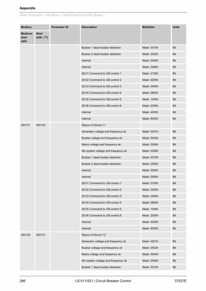
Modbus Parameter ID Description Multiplier Units
Modiconstartaddr.
Startaddr. (*1)
Busbar 1 dead busbar detection Mask: 0010h Bit
Busbar 2 dead busbar detection Mask: 0020h Bit
internal Mask: 0040h Bit
internal Mask: 0080h Bit
29.01 Command to CB-control 1 Mask: 0100h Bit
29.02 Command to CB-control 2 Mask: 0200h Bit
29.03 Command to CB-control 3 Mask: 0400h Bit
29.04 Command to CB-control 4 Mask: 0800h Bit
29.05 Command to CB-control 5 Mask: 1000h Bit
29.06 Command to CB-control 6 Mask: 2000h Bit
internal Mask: 4000h Bit
internal Mask: 8000h Bit
450131 450130 Status of Device 11
Generator voltage and frequency ok Mask: 0001h Bit
Busbar voltage and frequency ok Mask: 0002h Bit
Mains voltage and frequency ok Mask: 0004h Bit
4th system voltage and frequency ok Mask: 0008h Bit
Busbar 1 dead busbar detection Mask: 0010h Bit
Busbar 2 dead busbar detection Mask: 0020h Bit
internal Mask: 0040h Bit
internal Mask: 0080h Bit
29.01 Command to CB-control 1 Mask: 0100h Bit
29.02 Command to CB-control 2 Mask: 0200h Bit
29.03 Command to CB-control 3 Mask: 0400h Bit
29.04 Command to CB-control 4 Mask: 0800h Bit
29.05 Command to CB-control 5 Mask: 1000h Bit
29.06 Command to CB-control 6 Mask: 2000h Bit
internal Mask: 4000h Bit
internal Mask: 8000h Bit
450132 450131 Status of Device 12
Generator voltage and frequency ok Mask: 0001h Bit
Busbar voltage and frequency ok Mask: 0002h Bit
Mains voltage and frequency ok Mask: 0004h Bit
4th system voltage and frequency ok Mask: 0008h Bit
Busbar 1 dead busbar detection Mask: 0010h Bit
Appendix
Data Protocols > Modbus > Data Protocol 5300 (Basic ...
37527ELS-511/521 | Circuit Breaker Control286

Modbus Parameter ID Description Multiplier Units
Modiconstartaddr.
Startaddr. (*1)
Busbar 2 dead busbar detection Mask: 0020h Bit
internal Mask: 0040h Bit
internal Mask: 0080h Bit
29.01 Command to CB-control 1 Mask: 0100h Bit
29.02 Command to CB-control 2 Mask: 0200h Bit
29.03 Command to CB-control 3 Mask: 0400h Bit
29.04 Command to CB-control 4 Mask: 0800h Bit
29.05 Command to CB-control 5 Mask: 1000h Bit
29.06 Command to CB-control 6 Mask: 2000h Bit
internal Mask: 4000h Bit
internal Mask: 8000h Bit
450133 450132 Status of Device 13
Generator voltage and frequency ok Mask: 0001h Bit
Busbar voltage and frequency ok Mask: 0002h Bit
Mains voltage and frequency ok Mask: 0004h Bit
4th system voltage and frequency ok Mask: 0008h Bit
Busbar 1 dead busbar detection Mask: 0010h Bit
Busbar 2 dead busbar detection Mask: 0020h Bit
internal Mask: 0040h Bit
internal Mask: 0080h Bit
29.01 Command to CB-control 1 Mask: 0100h Bit
29.02 Command to CB-control 2 Mask: 0200h Bit
29.03 Command to CB-control 3 Mask: 0400h Bit
29.04 Command to CB-control 4 Mask: 0800h Bit
29.05 Command to CB-control 5 Mask: 1000h Bit
29.06 Command to CB-control 6 Mask: 2000h Bit
internal Mask: 4000h Bit
internal Mask: 8000h Bit
450134 450133 Status of Device 14
Generator voltage and frequency ok Mask: 0001h Bit
Busbar voltage and frequency ok Mask: 0002h Bit
Mains voltage and frequency ok Mask: 0004h Bit
4th system voltage and frequency ok Mask: 0008h Bit
Busbar 1 dead busbar detection Mask: 0010h Bit
Busbar 2 dead busbar detection Mask: 0020h Bit
Appendix
Data Protocols > Modbus > Data Protocol 5300 (Basic ...
37527E LS-511/521 | Circuit Breaker Control 287
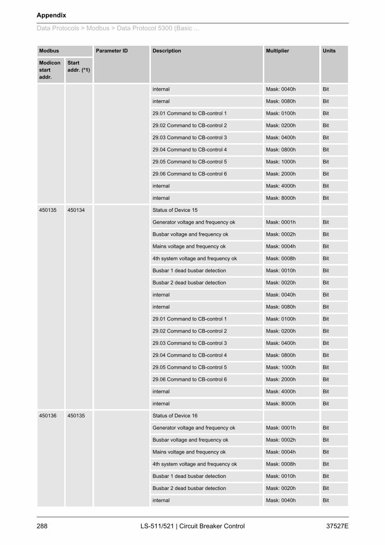
Modbus Parameter ID Description Multiplier Units
Modiconstartaddr.
Startaddr. (*1)
internal Mask: 0040h Bit
internal Mask: 0080h Bit
29.01 Command to CB-control 1 Mask: 0100h Bit
29.02 Command to CB-control 2 Mask: 0200h Bit
29.03 Command to CB-control 3 Mask: 0400h Bit
29.04 Command to CB-control 4 Mask: 0800h Bit
29.05 Command to CB-control 5 Mask: 1000h Bit
29.06 Command to CB-control 6 Mask: 2000h Bit
internal Mask: 4000h Bit
internal Mask: 8000h Bit
450135 450134 Status of Device 15
Generator voltage and frequency ok Mask: 0001h Bit
Busbar voltage and frequency ok Mask: 0002h Bit
Mains voltage and frequency ok Mask: 0004h Bit
4th system voltage and frequency ok Mask: 0008h Bit
Busbar 1 dead busbar detection Mask: 0010h Bit
Busbar 2 dead busbar detection Mask: 0020h Bit
internal Mask: 0040h Bit
internal Mask: 0080h Bit
29.01 Command to CB-control 1 Mask: 0100h Bit
29.02 Command to CB-control 2 Mask: 0200h Bit
29.03 Command to CB-control 3 Mask: 0400h Bit
29.04 Command to CB-control 4 Mask: 0800h Bit
29.05 Command to CB-control 5 Mask: 1000h Bit
29.06 Command to CB-control 6 Mask: 2000h Bit
internal Mask: 4000h Bit
internal Mask: 8000h Bit
450136 450135 Status of Device 16
Generator voltage and frequency ok Mask: 0001h Bit
Busbar voltage and frequency ok Mask: 0002h Bit
Mains voltage and frequency ok Mask: 0004h Bit
4th system voltage and frequency ok Mask: 0008h Bit
Busbar 1 dead busbar detection Mask: 0010h Bit
Busbar 2 dead busbar detection Mask: 0020h Bit
internal Mask: 0040h Bit
Appendix
Data Protocols > Modbus > Data Protocol 5300 (Basic ...
37527ELS-511/521 | Circuit Breaker Control288
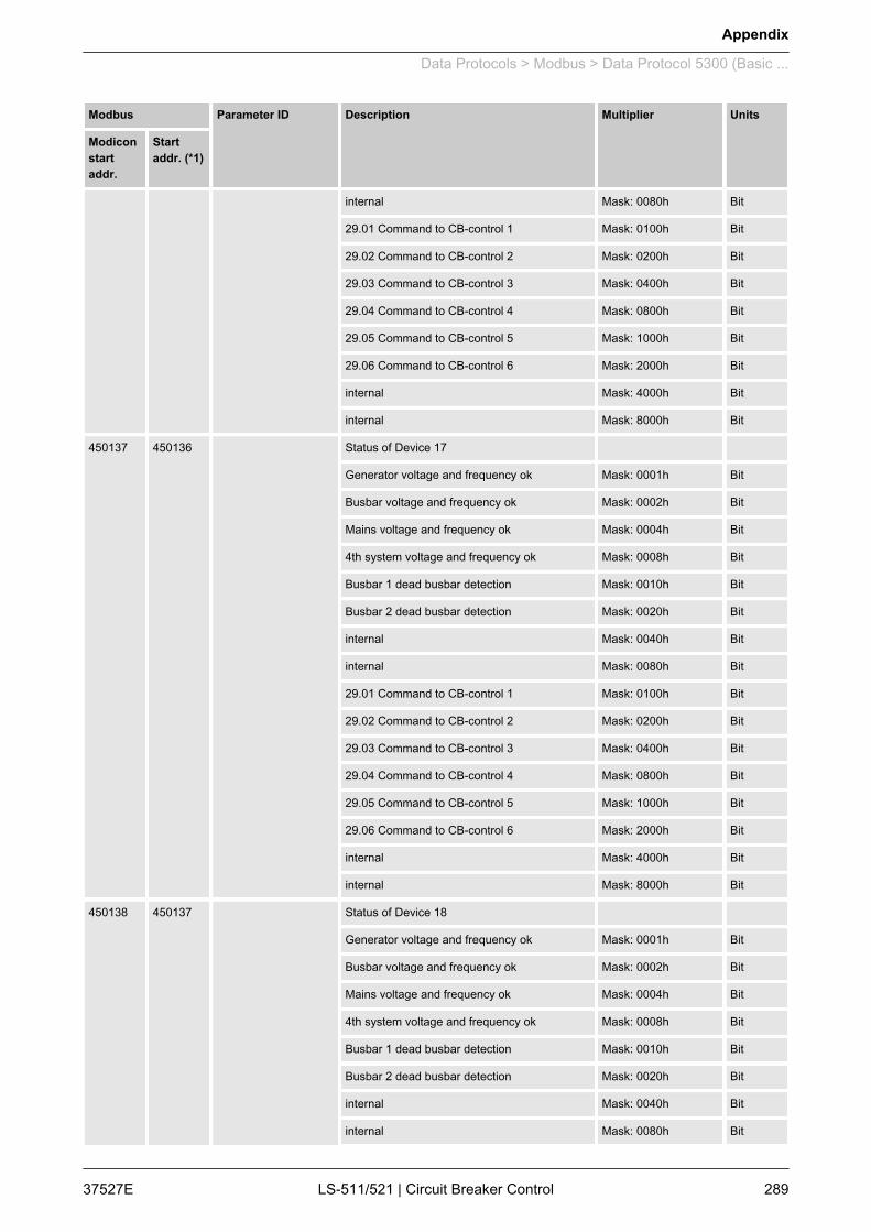
Modbus Parameter ID Description Multiplier Units
Modiconstartaddr.
Startaddr. (*1)
internal Mask: 0080h Bit
29.01 Command to CB-control 1 Mask: 0100h Bit
29.02 Command to CB-control 2 Mask: 0200h Bit
29.03 Command to CB-control 3 Mask: 0400h Bit
29.04 Command to CB-control 4 Mask: 0800h Bit
29.05 Command to CB-control 5 Mask: 1000h Bit
29.06 Command to CB-control 6 Mask: 2000h Bit
internal Mask: 4000h Bit
internal Mask: 8000h Bit
450137 450136 Status of Device 17
Generator voltage and frequency ok Mask: 0001h Bit
Busbar voltage and frequency ok Mask: 0002h Bit
Mains voltage and frequency ok Mask: 0004h Bit
4th system voltage and frequency ok Mask: 0008h Bit
Busbar 1 dead busbar detection Mask: 0010h Bit
Busbar 2 dead busbar detection Mask: 0020h Bit
internal Mask: 0040h Bit
internal Mask: 0080h Bit
29.01 Command to CB-control 1 Mask: 0100h Bit
29.02 Command to CB-control 2 Mask: 0200h Bit
29.03 Command to CB-control 3 Mask: 0400h Bit
29.04 Command to CB-control 4 Mask: 0800h Bit
29.05 Command to CB-control 5 Mask: 1000h Bit
29.06 Command to CB-control 6 Mask: 2000h Bit
internal Mask: 4000h Bit
internal Mask: 8000h Bit
450138 450137 Status of Device 18
Generator voltage and frequency ok Mask: 0001h Bit
Busbar voltage and frequency ok Mask: 0002h Bit
Mains voltage and frequency ok Mask: 0004h Bit
4th system voltage and frequency ok Mask: 0008h Bit
Busbar 1 dead busbar detection Mask: 0010h Bit
Busbar 2 dead busbar detection Mask: 0020h Bit
internal Mask: 0040h Bit
internal Mask: 0080h Bit
Appendix
Data Protocols > Modbus > Data Protocol 5300 (Basic ...
37527E LS-511/521 | Circuit Breaker Control 289
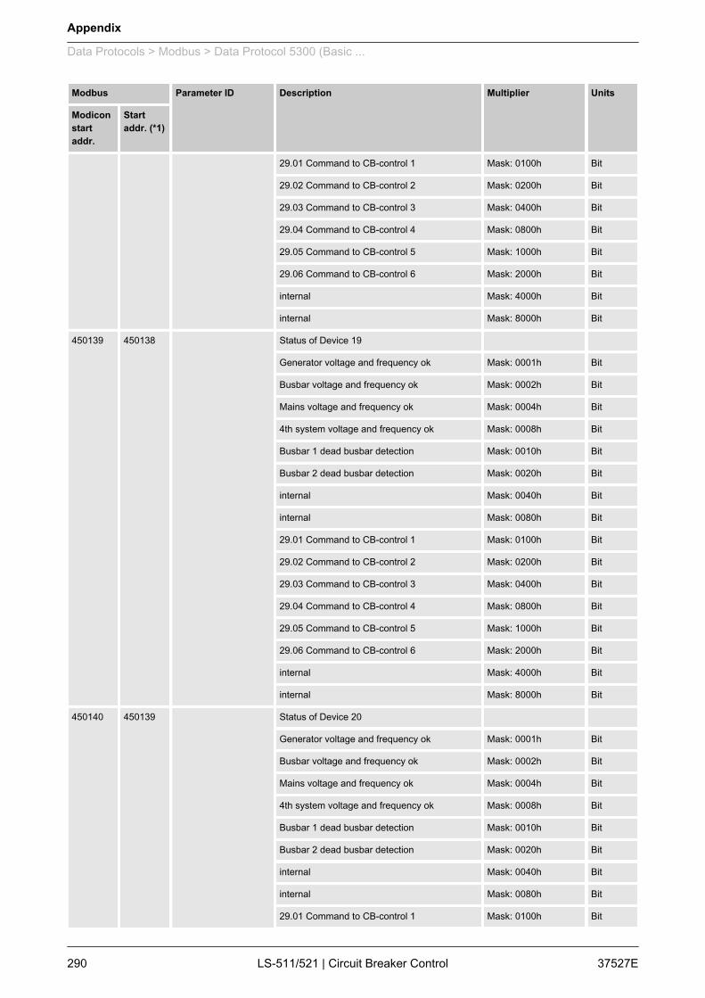
Modbus Parameter ID Description Multiplier Units
Modiconstartaddr.
Startaddr. (*1)
29.01 Command to CB-control 1 Mask: 0100h Bit
29.02 Command to CB-control 2 Mask: 0200h Bit
29.03 Command to CB-control 3 Mask: 0400h Bit
29.04 Command to CB-control 4 Mask: 0800h Bit
29.05 Command to CB-control 5 Mask: 1000h Bit
29.06 Command to CB-control 6 Mask: 2000h Bit
internal Mask: 4000h Bit
internal Mask: 8000h Bit
450139 450138 Status of Device 19
Generator voltage and frequency ok Mask: 0001h Bit
Busbar voltage and frequency ok Mask: 0002h Bit
Mains voltage and frequency ok Mask: 0004h Bit
4th system voltage and frequency ok Mask: 0008h Bit
Busbar 1 dead busbar detection Mask: 0010h Bit
Busbar 2 dead busbar detection Mask: 0020h Bit
internal Mask: 0040h Bit
internal Mask: 0080h Bit
29.01 Command to CB-control 1 Mask: 0100h Bit
29.02 Command to CB-control 2 Mask: 0200h Bit
29.03 Command to CB-control 3 Mask: 0400h Bit
29.04 Command to CB-control 4 Mask: 0800h Bit
29.05 Command to CB-control 5 Mask: 1000h Bit
29.06 Command to CB-control 6 Mask: 2000h Bit
internal Mask: 4000h Bit
internal Mask: 8000h Bit
450140 450139 Status of Device 20
Generator voltage and frequency ok Mask: 0001h Bit
Busbar voltage and frequency ok Mask: 0002h Bit
Mains voltage and frequency ok Mask: 0004h Bit
4th system voltage and frequency ok Mask: 0008h Bit
Busbar 1 dead busbar detection Mask: 0010h Bit
Busbar 2 dead busbar detection Mask: 0020h Bit
internal Mask: 0040h Bit
internal Mask: 0080h Bit
29.01 Command to CB-control 1 Mask: 0100h Bit
Appendix
Data Protocols > Modbus > Data Protocol 5300 (Basic ...
37527ELS-511/521 | Circuit Breaker Control290

Modbus Parameter ID Description Multiplier Units
Modiconstartaddr.
Startaddr. (*1)
29.02 Command to CB-control 2 Mask: 0200h Bit
29.03 Command to CB-control 3 Mask: 0400h Bit
29.04 Command to CB-control 4 Mask: 0800h Bit
29.05 Command to CB-control 5 Mask: 1000h Bit
29.06 Command to CB-control 6 Mask: 2000h Bit
internal Mask: 4000h Bit
internal Mask: 8000h Bit
450141 450140 Status of Device 21
Generator voltage and frequency ok Mask: 0001h Bit
Busbar voltage and frequency ok Mask: 0002h Bit
Mains voltage and frequency ok Mask: 0004h Bit
4th system voltage and frequency ok Mask: 0008h Bit
Busbar 1 dead busbar detection Mask: 0010h Bit
Busbar 2 dead busbar detection Mask: 0020h Bit
internal Mask: 0040h Bit
internal Mask: 0080h Bit
29.01 Command to CB-control 1 Mask: 0100h Bit
29.02 Command to CB-control 2 Mask: 0200h Bit
29.03 Command to CB-control 3 Mask: 0400h Bit
29.04 Command to CB-control 4 Mask: 0800h Bit
29.05 Command to CB-control 5 Mask: 1000h Bit
29.06 Command to CB-control 6 Mask: 2000h Bit
internal Mask: 4000h Bit
internal Mask: 8000h Bit
450142 450141 Status of Device 22
Generator voltage and frequency ok Mask: 0001h Bit
Busbar voltage and frequency ok Mask: 0002h Bit
Mains voltage and frequency ok Mask: 0004h Bit
4th system voltage and frequency ok Mask: 0008h Bit
Busbar 1 dead busbar detection Mask: 0010h Bit
Busbar 2 dead busbar detection Mask: 0020h Bit
internal Mask: 0040h Bit
internal Mask: 0080h Bit
29.01 Command to CB-control 1 Mask: 0100h Bit
29.02 Command to CB-control 2 Mask: 0200h Bit
Appendix
Data Protocols > Modbus > Data Protocol 5300 (Basic ...
37527E LS-511/521 | Circuit Breaker Control 291

Modbus Parameter ID Description Multiplier Units
Modiconstartaddr.
Startaddr. (*1)
29.03 Command to CB-control 3 Mask: 0400h Bit
29.04 Command to CB-control 4 Mask: 0800h Bit
29.05 Command to CB-control 5 Mask: 1000h Bit
29.06 Command to CB-control 6 Mask: 2000h Bit
internal Mask: 4000h Bit
internal Mask: 8000h Bit
450143 450142 Status of Device 23
Generator voltage and frequency ok Mask: 0001h Bit
Busbar voltage and frequency ok Mask: 0002h Bit
Mains voltage and frequency ok Mask: 0004h Bit
4th system voltage and frequency ok Mask: 0008h Bit
Busbar 1 dead busbar detection Mask: 0010h Bit
Busbar 2 dead busbar detection Mask: 0020h Bit
internal Mask: 0040h Bit
internal Mask: 0080h Bit
29.01 Command to CB-control 1 Mask: 0100h Bit
29.02 Command to CB-control 2 Mask: 0200h Bit
29.03 Command to CB-control 3 Mask: 0400h Bit
29.04 Command to CB-control 4 Mask: 0800h Bit
29.05 Command to CB-control 5 Mask: 1000h Bit
29.06 Command to CB-control 6 Mask: 2000h Bit
internal Mask: 4000h Bit
internal Mask: 8000h Bit
450144 450143 Status of Device 24
Generator voltage and frequency ok Mask: 0001h Bit
Busbar voltage and frequency ok Mask: 0002h Bit
Mains voltage and frequency ok Mask: 0004h Bit
4th system voltage and frequency ok Mask: 0008h Bit
Busbar 1 dead busbar detection Mask: 0010h Bit
Busbar 2 dead busbar detection Mask: 0020h Bit
internal Mask: 0040h Bit
internal Mask: 0080h Bit
29.01 Command to CB-control 1 Mask: 0100h Bit
29.02 Command to CB-control 2 Mask: 0200h Bit
29.03 Command to CB-control 3 Mask: 0400h Bit
Appendix
Data Protocols > Modbus > Data Protocol 5300 (Basic ...
37527ELS-511/521 | Circuit Breaker Control292

Modbus Parameter ID Description Multiplier Units
Modiconstartaddr.
Startaddr. (*1)
29.04 Command to CB-control 4 Mask: 0800h Bit
29.05 Command to CB-control 5 Mask: 1000h Bit
29.06 Command to CB-control 6 Mask: 2000h Bit
internal Mask: 4000h Bit
internal Mask: 8000h Bit
450145 450144 Status of Device 25
Generator voltage and frequency ok Mask: 0001h Bit
Busbar voltage and frequency ok Mask: 0002h Bit
Mains voltage and frequency ok Mask: 0004h Bit
4th system voltage and frequency ok Mask: 0008h Bit
Busbar 1 dead busbar detection Mask: 0010h Bit
Busbar 2 dead busbar detection Mask: 0020h Bit
internal Mask: 0040h Bit
internal Mask: 0080h Bit
29.01 Command to CB-control 1 Mask: 0100h Bit
29.02 Command to CB-control 2 Mask: 0200h Bit
29.03 Command to CB-control 3 Mask: 0400h Bit
29.04 Command to CB-control 4 Mask: 0800h Bit
29.05 Command to CB-control 5 Mask: 1000h Bit
29.06 Command to CB-control 6 Mask: 2000h Bit
internal Mask: 4000h Bit
internal Mask: 8000h Bit
450146 450145 Status of Device 26
Generator voltage and frequency ok Mask: 0001h Bit
Busbar voltage and frequency ok Mask: 0002h Bit
Mains voltage and frequency ok Mask: 0004h Bit
4th system voltage and frequency ok Mask: 0008h Bit
Busbar 1 dead busbar detection Mask: 0010h Bit
Busbar 2 dead busbar detection Mask: 0020h Bit
internal Mask: 0040h Bit
internal Mask: 0080h Bit
29.01 Command to CB-control 1 Mask: 0100h Bit
29.02 Command to CB-control 2 Mask: 0200h Bit
29.03 Command to CB-control 3 Mask: 0400h Bit
29.04 Command to CB-control 4 Mask: 0800h Bit
Appendix
Data Protocols > Modbus > Data Protocol 5300 (Basic ...
37527E LS-511/521 | Circuit Breaker Control 293
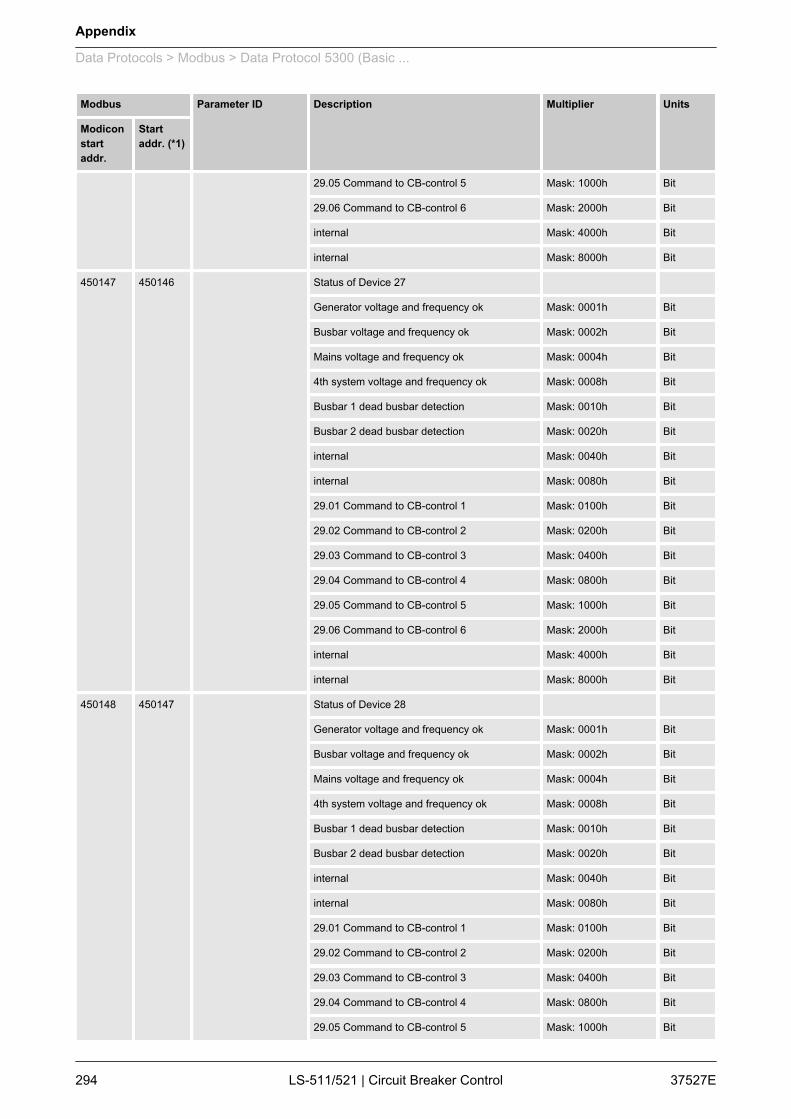
Modbus Parameter ID Description Multiplier Units
Modiconstartaddr.
Startaddr. (*1)
29.05 Command to CB-control 5 Mask: 1000h Bit
29.06 Command to CB-control 6 Mask: 2000h Bit
internal Mask: 4000h Bit
internal Mask: 8000h Bit
450147 450146 Status of Device 27
Generator voltage and frequency ok Mask: 0001h Bit
Busbar voltage and frequency ok Mask: 0002h Bit
Mains voltage and frequency ok Mask: 0004h Bit
4th system voltage and frequency ok Mask: 0008h Bit
Busbar 1 dead busbar detection Mask: 0010h Bit
Busbar 2 dead busbar detection Mask: 0020h Bit
internal Mask: 0040h Bit
internal Mask: 0080h Bit
29.01 Command to CB-control 1 Mask: 0100h Bit
29.02 Command to CB-control 2 Mask: 0200h Bit
29.03 Command to CB-control 3 Mask: 0400h Bit
29.04 Command to CB-control 4 Mask: 0800h Bit
29.05 Command to CB-control 5 Mask: 1000h Bit
29.06 Command to CB-control 6 Mask: 2000h Bit
internal Mask: 4000h Bit
internal Mask: 8000h Bit
450148 450147 Status of Device 28
Generator voltage and frequency ok Mask: 0001h Bit
Busbar voltage and frequency ok Mask: 0002h Bit
Mains voltage and frequency ok Mask: 0004h Bit
4th system voltage and frequency ok Mask: 0008h Bit
Busbar 1 dead busbar detection Mask: 0010h Bit
Busbar 2 dead busbar detection Mask: 0020h Bit
internal Mask: 0040h Bit
internal Mask: 0080h Bit
29.01 Command to CB-control 1 Mask: 0100h Bit
29.02 Command to CB-control 2 Mask: 0200h Bit
29.03 Command to CB-control 3 Mask: 0400h Bit
29.04 Command to CB-control 4 Mask: 0800h Bit
29.05 Command to CB-control 5 Mask: 1000h Bit
Appendix
Data Protocols > Modbus > Data Protocol 5300 (Basic ...
37527ELS-511/521 | Circuit Breaker Control294
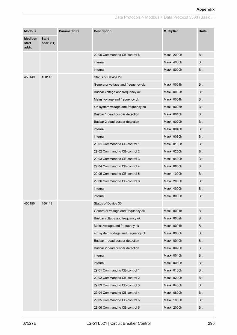
Modbus Parameter ID Description Multiplier Units
Modiconstartaddr.
Startaddr. (*1)
29.06 Command to CB-control 6 Mask: 2000h Bit
internal Mask: 4000h Bit
internal Mask: 8000h Bit
450149 450148 Status of Device 29
Generator voltage and frequency ok Mask: 0001h Bit
Busbar voltage and frequency ok Mask: 0002h Bit
Mains voltage and frequency ok Mask: 0004h Bit
4th system voltage and frequency ok Mask: 0008h Bit
Busbar 1 dead busbar detection Mask: 0010h Bit
Busbar 2 dead busbar detection Mask: 0020h Bit
internal Mask: 0040h Bit
internal Mask: 0080h Bit
29.01 Command to CB-control 1 Mask: 0100h Bit
29.02 Command to CB-control 2 Mask: 0200h Bit
29.03 Command to CB-control 3 Mask: 0400h Bit
29.04 Command to CB-control 4 Mask: 0800h Bit
29.05 Command to CB-control 5 Mask: 1000h Bit
29.06 Command to CB-control 6 Mask: 2000h Bit
internal Mask: 4000h Bit
internal Mask: 8000h Bit
450150 450149 Status of Device 30
Generator voltage and frequency ok Mask: 0001h Bit
Busbar voltage and frequency ok Mask: 0002h Bit
Mains voltage and frequency ok Mask: 0004h Bit
4th system voltage and frequency ok Mask: 0008h Bit
Busbar 1 dead busbar detection Mask: 0010h Bit
Busbar 2 dead busbar detection Mask: 0020h Bit
internal Mask: 0040h Bit
internal Mask: 0080h Bit
29.01 Command to CB-control 1 Mask: 0100h Bit
29.02 Command to CB-control 2 Mask: 0200h Bit
29.03 Command to CB-control 3 Mask: 0400h Bit
29.04 Command to CB-control 4 Mask: 0800h Bit
29.05 Command to CB-control 5 Mask: 1000h Bit
29.06 Command to CB-control 6 Mask: 2000h Bit
Appendix
Data Protocols > Modbus > Data Protocol 5300 (Basic ...
37527E LS-511/521 | Circuit Breaker Control 295
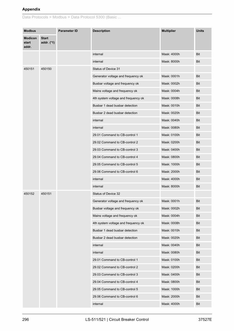
Modbus Parameter ID Description Multiplier Units
Modiconstartaddr.
Startaddr. (*1)
internal Mask: 4000h Bit
internal Mask: 8000h Bit
450151 450150 Status of Device 31
Generator voltage and frequency ok Mask: 0001h Bit
Busbar voltage and frequency ok Mask: 0002h Bit
Mains voltage and frequency ok Mask: 0004h Bit
4th system voltage and frequency ok Mask: 0008h Bit
Busbar 1 dead busbar detection Mask: 0010h Bit
Busbar 2 dead busbar detection Mask: 0020h Bit
internal Mask: 0040h Bit
internal Mask: 0080h Bit
29.01 Command to CB-control 1 Mask: 0100h Bit
29.02 Command to CB-control 2 Mask: 0200h Bit
29.03 Command to CB-control 3 Mask: 0400h Bit
29.04 Command to CB-control 4 Mask: 0800h Bit
29.05 Command to CB-control 5 Mask: 1000h Bit
29.06 Command to CB-control 6 Mask: 2000h Bit
internal Mask: 4000h Bit
internal Mask: 8000h Bit
450152 450151 Status of Device 32
Generator voltage and frequency ok Mask: 0001h Bit
Busbar voltage and frequency ok Mask: 0002h Bit
Mains voltage and frequency ok Mask: 0004h Bit
4th system voltage and frequency ok Mask: 0008h Bit
Busbar 1 dead busbar detection Mask: 0010h Bit
Busbar 2 dead busbar detection Mask: 0020h Bit
internal Mask: 0040h Bit
internal Mask: 0080h Bit
29.01 Command to CB-control 1 Mask: 0100h Bit
29.02 Command to CB-control 2 Mask: 0200h Bit
29.03 Command to CB-control 3 Mask: 0400h Bit
29.04 Command to CB-control 4 Mask: 0800h Bit
29.05 Command to CB-control 5 Mask: 1000h Bit
29.06 Command to CB-control 6 Mask: 2000h Bit
internal Mask: 4000h Bit
Appendix
Data Protocols > Modbus > Data Protocol 5300 (Basic ...
37527ELS-511/521 | Circuit Breaker Control296
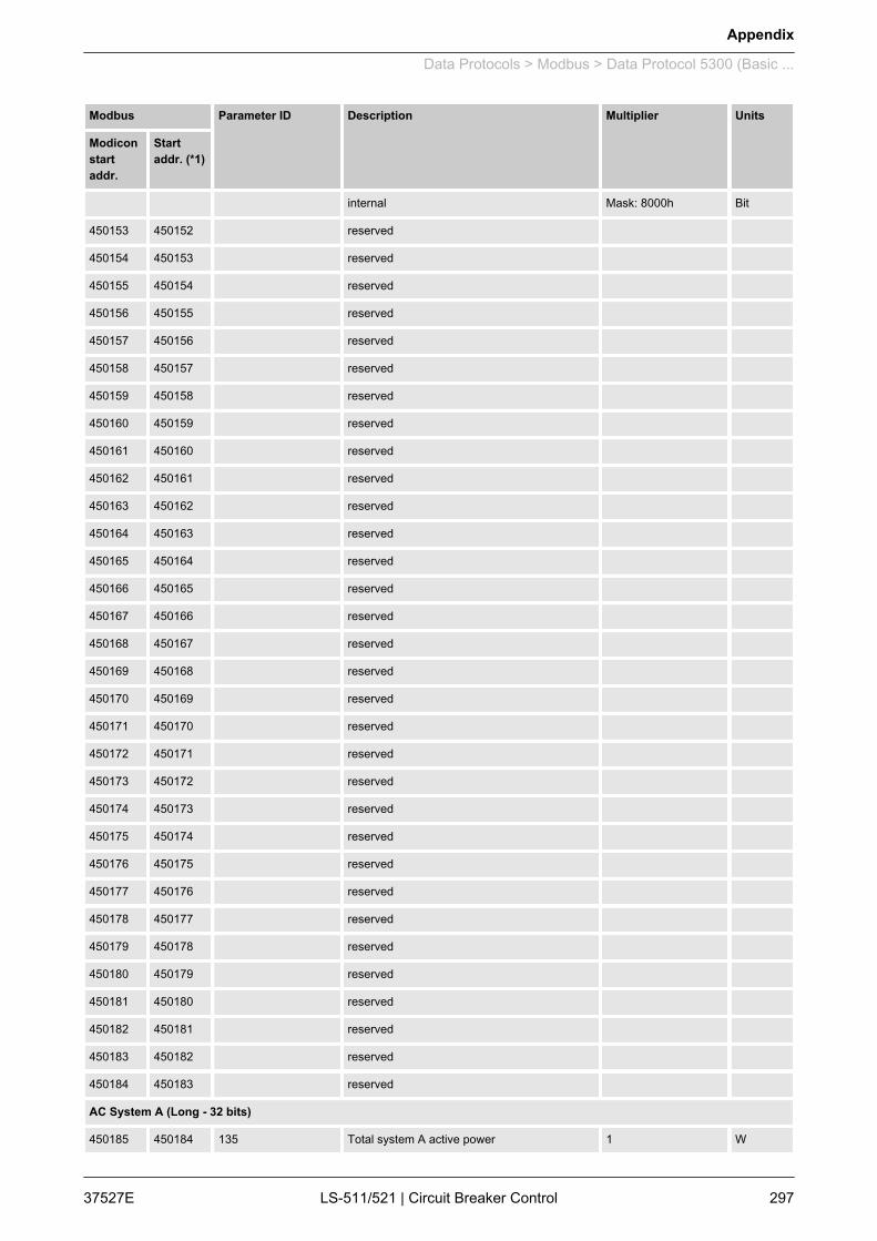
Modbus Parameter ID Description Multiplier Units
Modiconstartaddr.
Startaddr. (*1)
internal Mask: 8000h Bit
450153 450152 reserved
450154 450153 reserved
450155 450154 reserved
450156 450155 reserved
450157 450156 reserved
450158 450157 reserved
450159 450158 reserved
450160 450159 reserved
450161 450160 reserved
450162 450161 reserved
450163 450162 reserved
450164 450163 reserved
450165 450164 reserved
450166 450165 reserved
450167 450166 reserved
450168 450167 reserved
450169 450168 reserved
450170 450169 reserved
450171 450170 reserved
450172 450171 reserved
450173 450172 reserved
450174 450173 reserved
450175 450174 reserved
450176 450175 reserved
450177 450176 reserved
450178 450177 reserved
450179 450178 reserved
450180 450179 reserved
450181 450180 reserved
450182 450181 reserved
450183 450182 reserved
450184 450183 reserved
AC System A (Long - 32 bits)
450185 450184 135 Total system A active power 1 W
Appendix
Data Protocols > Modbus > Data Protocol 5300 (Basic ...
37527E LS-511/521 | Circuit Breaker Control 297
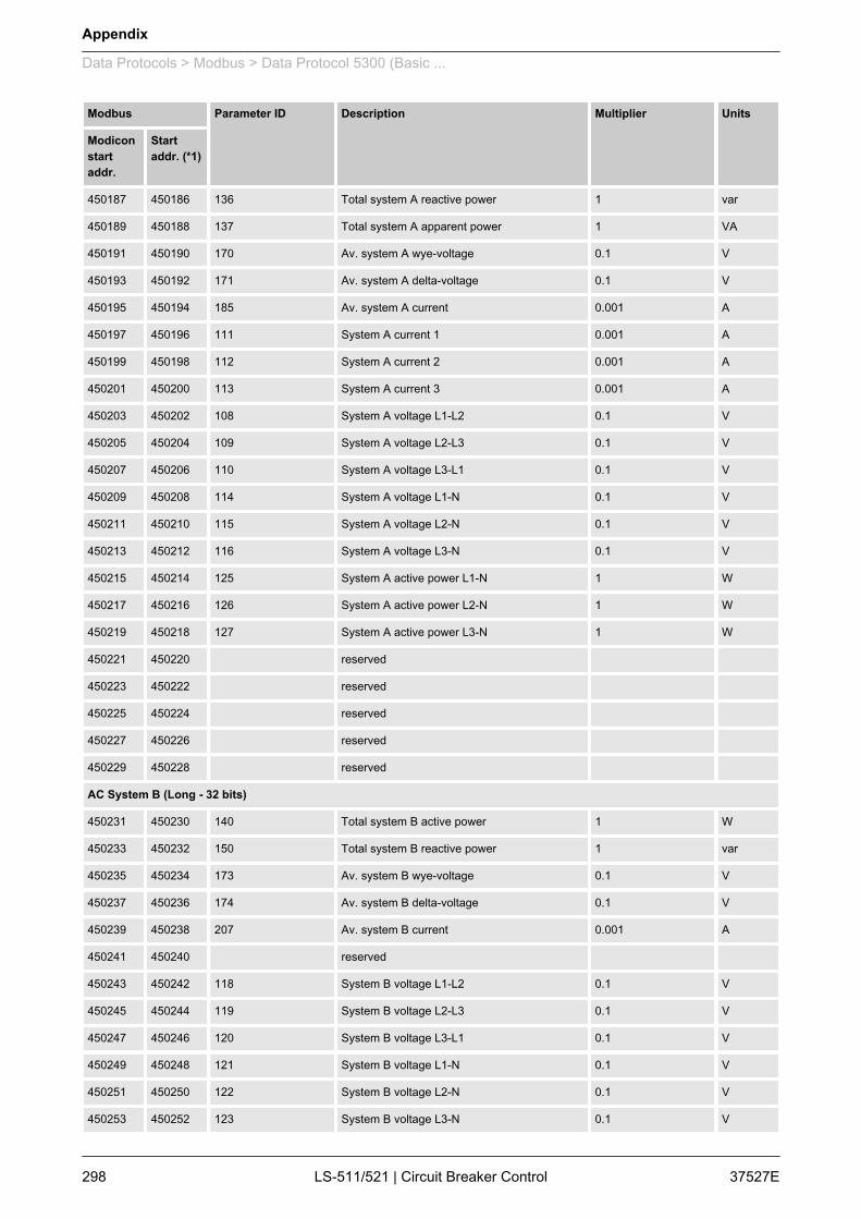
Modbus Parameter ID Description Multiplier Units
Modiconstartaddr.
Startaddr. (*1)
450187 450186 136 Total system A reactive power 1 var
450189 450188 137 Total system A apparent power 1 VA
450191 450190 170 Av. system A wye-voltage 0.1 V
450193 450192 171 Av. system A delta-voltage 0.1 V
450195 450194 185 Av. system A current 0.001 A
450197 450196 111 System A current 1 0.001 A
450199 450198 112 System A current 2 0.001 A
450201 450200 113 System A current 3 0.001 A
450203 450202 108 System A voltage L1-L2 0.1 V
450205 450204 109 System A voltage L2-L3 0.1 V
450207 450206 110 System A voltage L3-L1 0.1 V
450209 450208 114 System A voltage L1-N 0.1 V
450211 450210 115 System A voltage L2-N 0.1 V
450213 450212 116 System A voltage L3-N 0.1 V
450215 450214 125 System A active power L1-N 1 W
450217 450216 126 System A active power L2-N 1 W
450219 450218 127 System A active power L3-N 1 W
450221 450220 reserved
450223 450222 reserved
450225 450224 reserved
450227 450226 reserved
450229 450228 reserved
AC System B (Long - 32 bits)
450231 450230 140 Total system B active power 1 W
450233 450232 150 Total system B reactive power 1 var
450235 450234 173 Av. system B wye-voltage 0.1 V
450237 450236 174 Av. system B delta-voltage 0.1 V
450239 450238 207 Av. system B current 0.001 A
450241 450240 reserved
450243 450242 118 System B voltage L1-L2 0.1 V
450245 450244 119 System B voltage L2-L3 0.1 V
450247 450246 120 System B voltage L3-L1 0.1 V
450249 450248 121 System B voltage L1-N 0.1 V
450251 450250 122 System B voltage L2-N 0.1 V
450253 450252 123 System B voltage L3-N 0.1 V
Appendix
Data Protocols > Modbus > Data Protocol 5300 (Basic ...
37527ELS-511/521 | Circuit Breaker Control298
Modbus Parameter ID Description Multiplier Units
Modiconstartaddr.
Startaddr. (*1)
450255 450254 reserved
450257 450256 reserved
AC System Values (Long - 32 bits)
450259 450258 reserved
450261 450260 reserved
450263 450262 reserved
450265 450264 reserved
450267 450266 reserved
450269 450268 reserved
9.3 LogicsManager Reference9.3.1 LogicsManager Overview
The LogicsManager is used to customize the sequence of eventsin the control unit such as the start command of the engine or theoperation of control unit relay outputs. For example, the start rou‐tine may be programmed so that it requires the closing of a dis‐crete input or a preset time of day.Depending on the application mode of the unit, the number ofavailable relays that may be programmed with the LogicsManagerwill vary.Two independent time delays are provided for the configuredaction to take place and be reset.
Please do not use the output of an equation as input atthe same time. Such a configuration could decreasethe performace of the interfaces.
Fig. 129: LogicsManager - function overview
Structure and description of theLogicsManager
Appendix
LogicsManager Reference > LogicsManager Overview
37527E LS-511/521 | Circuit Breaker Control 299
n Command (variable)A list of parameters and functions is provided for the commandinputs.Examples of the parameters that may be configured into thesecommands are generator undervoltage thresholds 1 and 2,start fail, and cool down.These command variables are used to control the output func‐tion or relay.Refer to Ä Chapter 9.3.4 “Logical Command Variables”on page 304 for a complete list of all command variables.
n SignThe sign field can be used to invert the state of the commandor to fix its output to a logical true or false if the command is notneeded. Setting the sign to the NOT state changes the outputof the command variable from true to false or vice versa.
n OperatorA logical device such as AND or OR.
n (Logical) outputThe action or control sequence that occurs when all parame‐ters set into the LogicsManager are met.For a complete list of all logical outputs refer toÄ Chapter 9.3.3 “Logical Outputs” on page 302.
[Sx] - Sign{x}
Value {[Cx]} The value [Cx] is passed 1:1.
NOT Value {[Cx]} The opposite of the value [Cx] ispassed.
0 [False; always "0"] The value [Cx] is ignored and this logicpath will always be FALSE.
1 [True; always "1"] The value [Cx] is ignored and this logicpath will always be TRUE.
Table 43: Signs
[Ox] - Operator {x} AND Logical AND
NAND Logical negated AND
OR Logical OR
NOR Logical negated OR
XOR Exclusive OR
NXOR Exclusive negated OR
Table 44: Operators
For the various display formats of the correspondinglogical symbols refer to Ä Chapter 9.3.2 “Logical Sym‐bols” on page 301.
Appendix
LogicsManager Reference > LogicsManager Overview
37527ELS-511/521 | Circuit Breaker Control300

Using the values specified in the above table, the chain of com‐mands of the LogicsManager (for example: operating the relays,setting the flags, specification of the automatic functions) is config‐ured as follows:
[Ax] = ( ( [C1] & [S1] ) & [O1] & ( [C2] & [S2] ) ) & [O2] & ( [C3] & [S3] )
n Relay [R2] shall energize, whenever "Discrete input [DI 02]"is energized "AND" the control does "NOT" have a fault thatis "Alarm class C" "AND" does "NOT" have a fault that is"Alarm class D"
Programming example for theLogicsManager
Fig. 130: Programming example(ToolKit)
9.3.2 Logical SymbolsThe following symbols are used for the graphical programming ofthe LogicsManager. The LS-5 displays symbols according to theDIN 40 700 standard by default.
Fig. 131: Logical symbols
Configuration of the commandchain
Appendix
LogicsManager Reference > Logical Symbols
37527E LS-511/521 | Circuit Breaker Control 301
1 AND A IEC
2 OR B LS-5 (default: DIN 40 700)
3 NAND C ASA
US MIL
4 NOR D IEC617-12
5 NXOR
6 XOR
AND OR NAND NOR NXOR XOR
x1
x2
y x1
x2
y x1
x2
y x1
x2
y x1
x2
y x1
x2
y
0 0 0 0 0 0 0 0 1 0 0 1 0 0 1 0 0 0
0 1 0 0 1 1 0 1 1 0 1 0 0 1 0 0 1 1
1 0 0 1 0 1 1 0 1 1 0 0 1 0 0 1 0 1
1 1 1 1 1 1 1 1 0 1 1 0 1 1 1 1 1 0
Table 45: Truth table
9.3.3 Logical OutputsThe logical outputs or combinations may be grouped into three cat‐egories:n Internal logical flagsn Internal functionsn Relay outputs
The numbers of the logical outputs in the third columnmay again be used as input variable for other outputsin the LogicsManager.
16 internal logical flags may be programmed to activate/deactivatefunctions. This permits more than 3 commands to be included in alogical function. They may be used like "auxiliary flags".
Name Function Number
Flag 1 Internal flag 1 00.01
Flag 2 Internal flag 2 00.02
Flag 3 Internal flag 3 00.03
Flag 4 Internal flag 4 00.04
Flag 5 Internal flag 5 00.05
Flag 6 Internal flag 6 00.06
Internal flags
Appendix
LogicsManager Reference > Logical Outputs
37527ELS-511/521 | Circuit Breaker Control302
Name Function Number
Flag 7 Internal flag 7 00.07
Flag 8 Internal flag 8 00.08
Flag 9 Internal flag 9 00.30
Flag 10 Internal flag 10 00.31
Flag 11 Internal flag 11 00.32
Flag 12 Internal flag 12 00.33
Flag 13 Internal flag 13 00.34
Flag 14 Internal flag 14 00.35
Flag 15 Internal flag 15 00.36
Flag 16 Internal flag 16 00.37
5 internal logical LS-5 flags may be programmed to activate/deacti‐vate functions. This permits more than 3 commands to be includedin a logical function. They may be used like "auxiliary flags".These flags are transmitted on the CAN bus. The flags of all LS-5are received (as 26.01 to 27.80) by the LS-5 and the easYgen.They can be used as inputs for the LogicsManager.
Name Function Number
Flag 1 LS5 LS5 flag 1 24.41
Flag 2 LS5 LS5 flag 2 24.42
Flag 3 LS5 LS5 flag 3 24.43
Flag 4 LS5 LS5 flag 4 24.44
Flag 5 LS5 LS5 flag 5 24.45
The following logical functions may be used to activate/deactivatefunctions.
Name Function Number
External acknowledge The alarm acknowledgement is performed from an external source (param‐eter 12490 Ä p. 102)
00.15
Operation mode AUTO Activation of the AUTOMATIC operating mode (parameter 12510 Ä p. 122) 00.16
Operation mode MAN Activation of the MANUAL operating mode (parameter 12520 Ä p. 122) 00.17
Synchronization modeCHECK
Used for checking a synchronizer prior to commissioning. The system actively synchro‐nizes generator(s) by issuing speed and voltage bias commands, but does not issue abreaker closure command. (parameter 5728 Ä p. 115)
00.38
Synchronization modePERMISSIVE
The system acts in a synch check mode. The system will not issue speed or voltage biascommands to achieve synchronization, but if synchronization conditions are matched(frequency, phase, voltage and phase angle), the control will issue a breaker close com‐mand. (parameter 5728 Ä p. 115)
00.39
LS-5 flags
Internal functions
Appendix
LogicsManager Reference > Logical Outputs
37527E LS-511/521 | Circuit Breaker Control 303
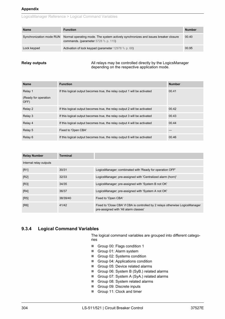
Name Function Number
Synchronization mode RUN Normal operating mode. The system actively synchronizes and issues breaker closurecommands. (parameter 5728 Ä p. 115)
00.40
Lock keypad Activation of lock keypad (parameter 12978 Ä p. 68) 00.95
All relays may be controlled directly by the LogicsManagerdepending on the respective application mode.
Name Function Number
Relay 1
(Ready for operationOFF)
If this logical output becomes true, the relay output 1 will be activated 00.41
Relay 2 If this logical output becomes true, the relay output 2 will be activated 00.42
Relay 3 If this logical output becomes true, the relay output 3 will be activated 00.43
Relay 4 If this logical output becomes true, the relay output 4 will be activated 00.44
Relay 5 Fixed to 'Open CBA' ---
Relay 6 If this logical output becomes true, the relay output 6 will be activated 00.46
Relay Number Terminal Internal relay outputs
[R1] 30/31 LogicsManager; combinated with 'Ready for operation OFF'
[R2] 32/33 LogicsManager; pre-assigned with 'Centralized alarm (horn)'
[R3] 34/35 LogicsManager; pre-assigned with 'System B not OK'
[R4] 36/37 LogicsManager; pre-assigned with 'System A not OK'
[R5] 38/39/40 Fixed to 'Open CBA'
[R6] 41/42 Fixed to 'Close CBA' if CBA is controlled by 2 relays otherwise LogicsManagerpre-assigned with 'All alarm classes'
9.3.4 Logical Command VariablesThe logical command variables are grouped into different catego‐riesn Group 00: Flags condition 1n Group 01: Alarm systemn Group 02: Systems conditionn Group 04: Applications conditionn Group 05: Device related alarmsn Group 06: System B (SyB.) related alarmsn Group 07: System A (SyA.) related alarmsn Group 08: System related alarmsn Group 09: Discrete inputsn Group 11: Clock and timer
Relay outputs
Appendix
LogicsManager Reference > Logical Command Variables
37527ELS-511/521 | Circuit Breaker Control304

n Group 13: Discrete outputsn Group 24: Flags condition 2n Group 26: Flags of LS5 (33 to 48)n Group 27: Flags of LS5 (49 to 64)n Group 28: LS5 system conditionsn Group 29: Commands of EG (1 to 16)n Group 29: Commands of EG (17 to 32)
9.3.4.1 Group 00: Flags Condition 1n Flags condition 1n Logic command variables 00.01-00.95Internal Flags are the result of the output of the logic ladders fromFlag 1 to 16. Flags are internal logic that can be sent to other flagsor Command variables.
No. ID Name Function Note
00.01 1 LM: Flag 1 Internal flag 1 Internal calculation; refer to Ä “Internal flags” on page 302
00.02 2 LM: Flag 2 Internal flag 2 Internal calculation; refer to Ä “Internal flags” on page 302
00.03 3 LM: Flag 3 Internal flag 3 Internal calculation; refer to Ä “Internal flags” on page 302
00.04 4 LM: Flag 4 Internal flag 4 Internal calculation; refer to Ä “Internal flags” on page 302
00.05 5 LM: Flag 5 Internal flag 5 Internal calculation; refer to Ä “Internal flags” on page 302
00.06 6 LM: Flag 6 Internal flag 6 Internal calculation; refer to Ä “Internal flags” on page 302
00.07 7 LM: Flag 7 Internal flag 7 Internal calculation; refer to Ä “Internal flags” on page 302
00.08 8 LM: Flag 8 Internal flag 8 Internal calculation; refer to Ä “Internal flags” on page 302
00.15 15 LM: External acknowledge The alarm acknowledgement isperformed from an externalsource
00.16 16 LM: Operation mode AUTO Activation of the AUTOMATICoperating mode
00.17 17 LM: Operation mode MAN Activation of the MANUAL op.mode
00.30 30 LM: Flag 9 Internal flag 9 Internal calculation; refer to Ä “Internal flags” on page 302
00.31 31 LM: Flag 10 Internal flag 10 Internal calculation; refer to Ä “Internal flags” on page 302
00.32 32 LM: Flag 11 Internal flag 11 Internal calculation; refer to Ä “Internal flags” on page 302
Appendix
LogicsManager Reference > Logical Command Variables > Group 00: Flags Condition 1
37527E LS-511/521 | Circuit Breaker Control 305
No. ID Name Function Note
00.33 33 LM: Flag 12 Internal flag 12 Internal calculation; refer to Ä “Internal flags” on page 302
00.34 34 LM: Flag 13 Internal flag 13 Internal calculation; refer to Ä “Internal flags” on page 302
00.35 35 LM: Flag 14 Internal flag 14 Internal calculation; refer to Ä “Internal flags” on page 302
00.36 36 LM: Flag 15 Internal flag 15 Internal calculation; refer to Ä “Internal flags” on page 302
00.37 37 LM: Flag 16 Internal flag 16 Internal calculation; refer to Ä “Internal flags” on page 302
00.38 38 LM: Syn. Mode CHECK Synchronisation mode check isactive
00.39 39 LM: Syn. Mode PERM Synchronisation mode permis‐sive is active
00.40 40 LM: Syn. Mode RUN Synchronisation mode run isactive
00.41 41 LM: Relay 1 TRUE, if the LogicsManagercondition driving this relay isfulfilled00.42 42 LM: Relay 2
00.43 43 LM: Relay 3
00.44 44 LM: Relay 4
00.45 45 Reserved
00.46 46 LM: Relay 6
00.95 95 LM: Lock Keypad Lock keypad is active
9.3.4.2 Group 01: Alarm Systemn Alarm systemn Logic command variables 01.01-01.12Alarm classes may be configured as command variables for all log‐ical outputs in the LogicsManager. Refer to Ä Chapter 9.4.1 “AlarmClasses” on page 328 for a description of the alarm classes.
No. ID Name / Function Note
01.01 101 Alarm class A TRUE as long as an alarm of this alarmclass is active or latched (triggered)
01.02 102 Alarm class B TRUE as long as an alarm of this alarmclass is active or latched (triggered)
01.03 103 Alarm class C TRUE as long as an alarm of this alarmclass is active or latched (triggered)
01.04 104 Alarm class D TRUE as long as an alarm of this alarmclass is active or latched (triggered)
01.05 105 Alarm class E TRUE as long as an alarm of this alarmclass is active or latched (triggered)
Appendix
LogicsManager Reference > Logical Command Variables > Group 01: Alarm System
37527ELS-511/521 | Circuit Breaker Control306
No. ID Name / Function Note
01.06 106 Alarm class F TRUE as long as an alarm of this alarmclass is active or latched (triggered)
01.07 107 All alarm classes TRUE as long as at least one alarm of thealarm classes A/B/C/D/E/F is active orlatched (triggered)
01.08 108 Warning alarm TRUE as long as at least one alarm of thealarm classes A/B is active or latched (trig‐gered)
01.09 109 Shutdown alarm TRUE as long as at least one alarm of thealarm classes C/D/E/F is active or latched(triggered)
01.10 110 Centralized alarm TRUE as long as at least one alarm of thealarm classes B/C/D/E/F is active orlatched (triggered)
01.11 111 New alarm triggered TRUE if any alarm has been triggered untilit is acknowledged
01.12 112 Horn True if a new alarm is triggered and time(parameter 1756 Ä p. 102) for horn resethas not exceeded.
9.3.4.3 Group 02: Systems Conditionn Systems conditionn Logic command variables 02.03-02.25The status of the system may be used as command variable in alogical output to set parameters for customized operations.
No. ID Name Function Note
02.03 203 SyB. voltage ok SyB. voltage within operatingwindow
TRUE as long as the SyB.voltage is within the operatingwindow
02.04 204 SyB. frequency ok SyB. frequency within operatingwindow
TRUE as long as the SyB. fre‐quency is within the operatingwindow
02.05 205 SyB. voltage / frequency ok SyB. voltage and frequencywithin operating windows
TRUE as long as the SyB.voltage and frequency arewithin the operating windows(02.03. and 02.04 are TRUE)
02.09 209 SyA. voltage ok SyA. voltage within operatingwindow
TRUE as long as the SyA.voltage is within the operatingwindow
02.10 210 SyA. frequency ok SyA. frequency within operatingwindow
TRUE as long as the SyA. fre‐quency is within the operatingwindow
02.11 211 SyA. voltage / frequency ok SyA. voltage and frequencywithin operating windows
TRUE as long as the SyA.voltage and frequency arewithin the operating windows(02.09. and 02.10 are TRUE)
Appendix
LogicsManager Reference > Logical Command Variables > Group 02: Systems Condition
37527E LS-511/521 | Circuit Breaker Control 307
No. ID Name Function Note
02.12 212 SyA. rotation CCW SyA. voltage: rotating directionCCW
TRUE as long as the respectiverotation field is detected in caseof a three-phase voltage meas‐urement at the respectivemeasuring location
02.13 213 SyA. rotation CW SyA. voltage: rotating directionCW
02.14 214 SyB. rotation CCW SyB. voltage: rotating directionCCW
02.15 215 SyB. rotation CW SyB. voltage: rotating directionCW
02.23 223 System A is dead System A is dead TRUE as long as system Avoltage is below the leveldefined by parameter5820 Ä p. 115.
02.24 224 System B is dead System B is dead TRUE as long as system Bvoltage is below the leveldefined by parameter5820 Ä p. 115.
02.25 225 Gen. is mains par. Indicates generator is in mainsparallel operation
TRUE if system A (B) is mainsconnected and system B (A) isvariable and CBA is closed andat least one GCB (easYgen) ata relevant segment is closed.(It can be used to enable mainsdecoupling.)
02.28 228 Sync. check relay Indicates phase matching orDead Bus conditions met
TRUE if synchronization condi‐tions are TRUE defined byparameters 5711 Ä p. 112,5712 Ä p. 113, 5710 Ä p. 113,8825 Ä p. 113, 8824 Ä p. 113,5712 Ä p. 113, 5714 Ä p. 114and 5717 Ä p. 114 OR if DeadBus conditions are TRUEdefined by parameters8801 Ä p. 114, 5820 Ä p. 115,8805 Ä p. 115, 8802 Ä p. 114,8803 Ä p. 114 and8804 Ä p. 114.
Warning
No deadbus interlocking.
02.29 229 Sync. condition Indicates phase matching con‐ditions met
TRUE if synchronization condi‐tions are TRUE defined byparameters 5711 Ä p. 112,5712 Ä p. 113, 5710 Ä p. 113,8825 Ä p. 113, 8824 Ä p. 113,5712 Ä p. 113, 5714 Ä p. 114and 5717 Ä p. 114.
02.30 230 Dead bus cl. condition Indicates Dead Bus conditionsmet
TRUE if Dead Bus conditionsare TRUE defined by parame‐ters 8801 Ä p. 114,5820 Ä p. 115, 8805 Ä p. 115,8802 Ä p. 114, 8803 Ä p. 114and 8804 Ä p. 114.
Warning
No deadbus interlocking.
Appendix
LogicsManager Reference > Logical Command Variables > Group 02: Systems Condition
37527ELS-511/521 | Circuit Breaker Control308

9.3.4.4 Group 04: Applications Conditionn Applications conditionn Logic command variables 4.01-04.63These operating statuses may be used as command variable in alogical output to set parameters for customized operations.
No. ID Name Function Note
04.01 401 Auto mode AUTOMATIC operating modeactive
TRUE in AUTOMATIC oper‐ating mode
04.03 403 Manual mode MANUAL operating modeactive
TRUE in MANUAL operatingmode
04.04 404 Lamp test A lamp test is being performed TRUE if the lamp test is active
04.05 405 Acknowledge "Acknowledge" push button hasbeen pressed or an externalacknowledgment via Logi‐csManager
This condition is TRUE forapprox. 40 ms and must beextended utilizing a delay time
04.07 407 CBA is closed CBA is closed only TRUE if DI 8 (Reply CBA) isde-energized
04.11 411 Mains settling Mains settling time active TRUE in LS5 or single LS5mode while mains settling timeis running.
04.21 421 Syn. CBA is active Synchronization CBA is active TRUE if the CBA shall besynchronized until the CBA isclosed
04.22 422 Opening CBA active Opening CBA is active TRUE if an CBA open com‐mand is issued until DI 8 (ReplyCBA) is energized
04.23 423 Closing CBA active Closing CBA is active TRUE if an CBA close com‐mand is issued; same functionas relay 5 or 6 (cf. parameter8800 Ä p. 109)
04.29 429 CBA unloading CBA unloading sequence isactive
TRUE if CBA open withunloading is active.
04.44 444 Remote control Bit 1 Free control bit 1 is activated Refer to Ä Chapter 7 “Inter‐faces And Protocols”on page 22504.45 445 Remote control Bit 2 Free control bit 2 is activated
04.46 446 Remote control Bit 3 Free control bit 3 is activated
04.47 447 Remote control Bit 4 Free control bit 4 is activated
04.48 448 Remote control Bit 5 Free control bit 5 is activated
04.49 449 Remote control Bit 6 Free control bit 6 is activated
04.50 450 Remote control Bit 7 Free control bit 7 is activated
04.51 451 Remote control Bit 8 Free control bit 8 is activated
04.52 452 Remote control Bit 9 Free control bit 9 is activated
04.53 453 Remote control Bit 10 Free control bit 10 is activated
04.54 454 Remote control Bit 11 Free control bit 11 is activated
04.55 455 Remote control Bit 12 Free control bit 12 is activated
Appendix
LogicsManager Reference > Logical Command Variables > Group 04: Applications Con...
37527E LS-511/521 | Circuit Breaker Control 309
No. ID Name Function Note
04.56 456 Remote control Bit 13 Free control bit 13 is activated
04.57 457 Remote control Bit 14 Free control bit 14 is activated
04.58 458 Remote control Bit 15 Free control bit 15 is activated
04.59 459 Remote control Bit 16 Free control bit 16 is activated
04.61 461 Syn. mains close active Synchronous mains closureprocedure is active.
TRUE if
n System A detected asmains connected and
n System B detected asmains connected and
n Angle is in range (param‐eter 8821 Ä p. 110,8822 Ä p. 110) and
n Parameter "Connectsynchr. mains(8820 Ä p. 109) is "Yes"and
n CBA is enabled andn System A is ok andn System B is ok.
04.62 462 Dead bus close active Dead bus closure procedure isactive.
TRUE if
n Dead bus closure isallowed (parameter8801 Ä p. 114 to8804 Ä p. 114) and
n Dead bus conditions aretrue (parameter8801 Ä p. 114 to8805 Ä p. 115,5820 Ä p. 115) and
n CBA is enabled.
04.63 463 Syn.segm. close act. Synchronous segments closureprocedure is active.
TRUE if
n System A and B arealready connected and
n Angle is in range (param‐eter 8821 Ä p. 110,8822 Ä p. 110) and
n Parameter "Connectsynchr. segments(8852 Ä p. 110) is "Yes"and
n CBA is enabled andn System A is ok andn System B is ok.
9.3.4.5 Group 05: Device Related Alarmsn Device related alarmsn Logic command variables 05.15
Appendix
LogicsManager Reference > Logical Command Variables > Group 05: Device Related A...
37527ELS-511/521 | Circuit Breaker Control310

These device alarms may be used as command variable in a log‐ical output to set parameters for customized operations.
No. ID Name / Function Note
05.15 515 EEprom failure TRUE = alarm latched (triggered)
FALSE = alarm acknowledged
9.3.4.6 Group 06: System B Related Alarmsn System B related alarmsn Logic command variables 06.21These system B alarms may be used as command variable in alogical output to set parameters for customized operations.
No. ID Name / Function Note
06.21 621 SyB. phase rotation TRUE = alarm latched (triggered)
FALSE = alarm acknowledged
9.3.4.7 Group 07: System A Related Alarmsn System A related alarmsn Logic command variables 07.05-07.30These system A alarms may be used as command variable in alogical output to set parameters for customized operations.
No. ID Function Note
07.05 705 SyA. phase rotation TRUE = alarm latched (triggered)
FALSE = alarm acknowledged07.06 706 SyA. overfrequency (limit) 1
07.07 707 SyA. overfrequency (limit) 2
07.08 708 SyA. underfrequency (limit) 1
07.09 709 SyA. underfrequency (limit) 2
07.10 710 SyA. overvoltage (limit) 1
07.11 711 SyA. overvoltage (limit) 2
07.12 712 SyA. undervoltage (limit) 1
07.13 713 SyA. undervoltage (limit) 2
07.14 714 SyA. phase shift
07.15 715 SyA. df/dt
07.25 725 SyA. decoupling
07.26 726 SyA. voltage asymmetry
07.27 727 SyA. voltage increase.
Appendix
LogicsManager Reference > Logical Command Variables > Group 07: System A Related...
37527E LS-511/521 | Circuit Breaker Control 311
No. ID Function Note
07.28 728 Time-dep. voltage
07.29 729 SyA. QV mon. (limit) 1
07.30 730 SyA. QV mon. (limit) 2
9.3.4.8 Group 08: System Related Alarmsn System related alarmsn Logic command variables 08.01-08.36These system alarms may be used as command variable in a log‐ical output n to set parameters for customized operations.
No. ID Function Note
08.01 801 Battery overvoltage (limit) 1 TRUE = alarm latched (triggered)
FALSE = alarm acknowledged08.02 802 Battery overvoltage (limit) 2
08.03 803 Battery undervoltage (limit) 1
08.04 804 Battery undervoltage (limit) 2
08.07 807 CBA fail to close
08.08 808 CBA fail to open
08.17 817 Missing LS5
08.18 818 CANopen Interface 1
08.31 831 Synchronization time CBA
08.33 833 Phase rotation mismatch
08.36 836 CBA unload mismatch
9.3.4.9 Group 09: Discrete Inputsn Discrete inputsn Logic command variables 09.01-09.08The discrete inputs may be used as command variable in a logicaloutput to set parameters for customized operations.
No. ID Function Note
09.01 901 DI 1 (Discrete input [DI 01]) TRUE = logical "1" (delay times and N.O./N.C. parameters are ignored)
FALSE = logical "0" (alarm has beenacknowledged or immediately after TRUEcondition is not present anymore, if Controlis configured as alarm class)
09.02 902 DI 2 (Discrete input [DI 02])
09.03 903 DI 3 (Discrete input [DI 03])
09.04 904 DI 4 (Discrete input [DI 04])
09.05 905 DI 5 (Discrete input [DI 05])
09.06 906 DI 6 (Discrete input [DI 06])
Appendix
LogicsManager Reference > Logical Command Variables > Group 09: Discrete Inputs
37527ELS-511/521 | Circuit Breaker Control312

No. ID Function Note
09.07 907 DI 7 (Discrete input [DI 07])
09.08 908 DI 8 (Discrete input [DI 08])
9.3.4.10 Group 11: Clock And Timern Clock and timern Logic command variables 11.01-11.07Time functions may be used as command variable in a logicaloutput.
No. ID Name / Function Note
11.01 1101 Timer 1 (exceeded) Refer to Ä Chapter 4.1.1 “Configure Lan‐guage/Clock” on page 61.
11.02 1102 Timer 2 (exceeded) Refer to Ä Chapter 4.1.1 “Configure Lan‐guage/Clock” on page 61.
11.03 1103 Active weekday (equal to setting) Refer to Ä Chapter 4.1.1 “Configure Lan‐guage/Clock” on page 61.
11.04 1104 Active day (equal to setting) Refer to Ä Chapter 4.1.1 “Configure Lan‐guage/Clock” on page 61.
11.05 1105 Active hour (equal to setting) Refer to Ä Chapter 4.1.1 “Configure Lan‐guage/Clock” on page 61.
11.06 1106 Active minute (equal to setting) Refer to Ä Chapter 4.1.1 “Configure Lan‐guage/Clock” on page 61.
11.07 1107 Active second (equal to setting) Refer to Ä Chapter 4.1.1 “Configure Lan‐guage/Clock” on page 61.
9.3.4.11 Group 13: Discrete Outputsn Discrete outputsn Logic command variables 13.01-13.12The discrete outputs may be used as command variable in a log‐ical output.
No. ID Name / Function Note
13.01 1301 Discrete output DO1 [R01] TRUE = logical "1" (this condition indicatesthe logical status of the internal relays)
FALSE = logical "0" (this condition indi‐cates the logical status of the internalrelays)
13.02 1302 Discrete output DO2 [R02]
13.03 1303 Discrete output DO3 [R03]
13.04 1304 Discrete output DO4 [R04]
13.05 1305 Discrete output DO5 [R05]
13.06 1306 Discrete output DO6 [R06]
Appendix
LogicsManager Reference > Logical Command Variables > Group 13: Discrete Outputs
37527E LS-511/521 | Circuit Breaker Control 313

9.3.4.12 Group 24: Flags Condition 2n Flags condition 2n Logic command variables 24.31-24.58The discrete outputs may be used as command variable in a log‐ical output.
No. ID Name / Function Note
24.31 2131 LM: Enable SyA dec.
24.32 2132 LM: Open CBA
24.33 2133 LM: Immediate open CBA
24.34 2134 LM: Enable to close CBA
24.39 2139 LM: Isol. swi. open
24.40 2140 LM: Lock Monitoring
24.41 2141 LM: Flag 1 LS5
24.42 2142 LM: Flag 2 LS5
24.43 2143 LM: Flag 3 LS5
24.44 2144 LM: Flag 4 LS5
24.45 2145 LM: Flag 5 LS5
24.46 2146 LM: Open CBA in MAN
24.47 2147 LM: Close CBA in MAN
24.51 2151 LM: LED 1 (System A in range) These command variables and the core‐sponding equations are available in thedisplay version in ToolKit and the HMI,even if the LEDs are not available. In thedisplay version the variables can be usedas additional internal flags and are locatedthere.
24.52 2152 LM: LED 2 (System B in range)
24.53 2153 LM: LED 3 (Breaker is closed)
24.54 2154 LM: LED 4 (Synchronization is active)
24.55 2155 LM: LED 5 (Breaker close command)
24.56 2156 LM: LED 6 (Breaker open failure)
24.57 2157 LM: LED 7 (Breaker close failure)
24.58 2158 LM: LED 8 (Communication failure)
Note: Indicates that the multi-unit missingmembers monitoring function (parameter4060 Ä p. 106) has tripped. See also Logi‐csManager "LED 8" (parameter12969 Ä p. 135).
Appendix
LogicsManager Reference > Logical Command Variables > Group 24: Flags Condition 2
37527ELS-511/521 | Circuit Breaker Control314
9.3.4.13 Group 26: Flags Of LS5 (33 to 48)n Flags of LS5 (33 to 48)n Logic command variables 26.01-26.80
No. ID Name / Function Note
26.01 2201 Flag 1 LS5 device 33 TRUE if LogicsManager 12952 in LS-5device no. {x} is activated [x = 33 to 48]
26.02 2202 Flag 2 LS5 device 33 TRUE if LogicsManager 12953 in LS-5device no. {x} is activated [x = 33 to 48]
26.03 2203 Flag 3 LS5 device 33 TRUE if LogicsManager 12954 in LS-5device no. {x} is activated [x = 33 to 48]
26.04 2204 Flag 4 LS5 device 33 TRUE if LogicsManager 12955 in LS-5device no. {x} is activated [x = 33 to 48]
26.05 2205 Flag 5 LS5 device 33 TRUE if LogicsManager 12956 in LS-5device no. {x} is activated [x = 33 to 48]
26.06 2206 Flag 1 LS5 device 34
26.07 2207 Flag 2 LS5 device 34
26.08 2208 Flag 3 LS5 device 34
26.09 2209 Flag 4 LS5 device 34
26.10 2210 Flag 5 LS5 device 34
26.11 2211 Flag 1 LS5 device 35
26.12 2212 Flag 2 LS5 device 35
26.13 2213 Flag 3 LS5 device 35
26.14 2214 Flag 4 LS5 device 35
26.15 2215 Flag 5 LS5 device 35
26.16 2216 Flag 1 LS5 device 36
26.17 2217 Flag 2 LS5 device 36
26.18 2218 Flag 3 LS5 device 36
26.19 2219 Flag 4 LS5 device 36
26.20 2220 Flag 5 LS5 device 36
26.21 2221 Flag 1 LS5 device 37
26.22 2222 Flag 2 LS5 device 37
26.23 2223 Flag 3 LS5 device 37
26.24 2224 Flag 4 LS5 device 37
26.25 2225 Flag 5 LS5 device 37
26.26 2226 Flag 1 LS5 device 38
26.27 2227 Flag 2 LS5 device 38
26.28 2228 Flag 3 LS5 device 38
26.29 2229 Flag 4 LS5 device 38
26.30 2230 Flag 5 LS5 device 38
Appendix
LogicsManager Reference > Logical Command Variables > Group 26: Flags Of LS5 (33...
37527E LS-511/521 | Circuit Breaker Control 315

No. ID Name / Function Note
26.31 2231 Flag 1 LS5 device 39
26.32 2232 Flag 2 LS5 device 39
26.33 2233 Flag 3 LS5 device 39
26.34 2234 Flag 4 LS5 device 39
26.35 2235 Flag 5 LS5 device 39
26.36 2236 Flag 1 LS5 device 40
26.37 2237 Flag 2 LS5 device 40
26.38 2238 Flag 3 LS5 device 40
26.39 2239 Flag 4 LS5 device 40
26.40 2240 Flag 5 LS5 device 40
26.41 2241 Flag 1 LS5 device 41
26.42 2242 Flag 2 LS5 device 41
26.43 2243 Flag 3 LS5 device 41
26.44 2244 Flag 4 LS5 device 41
26.45 2245 Flag 5 LS5 device 41
26.46 2246 Flag 1 LS5 device 42
26.47 2247 Flag 2 LS5 device 42
26.48 2248 Flag 3 LS5 device 42
26.49 2249 Flag 4 LS5 device 42
26.50 2250 Flag 5 LS5 device 42
26.51 2251 Flag 1 LS5 device 43
26.52 2252 Flag 2 LS5 device 43
26.53 2253 Flag 3 LS5 device 43
26.54 2254 Flag 4 LS5 device 43
26.55 2255 Flag 5 LS5 device 43
26.56 2256 Flag 1 LS5 device 44
26.57 2257 Flag 2 LS5 device 44
26.58 2258 Flag 3 LS5 device 44
26.59 2259 Flag 4 LS5 device 44
26.60 2260 Flag 5 LS5 device 44
26.61 2261 Flag 1 LS5 device 45
26.62 2262 Flag 2 LS5 device 45
26.63 2263 Flag 3 LS5 device 45
26.64 2264 Flag 4 LS5 device 45
26.65 2265 Flag 5 LS5 device 45
26.66 2266 Flag 1 LS5 device 46
26.67 2267 Flag 2 LS5 device 46
Appendix
LogicsManager Reference > Logical Command Variables > Group 26: Flags Of LS5 (33...
37527ELS-511/521 | Circuit Breaker Control316
No. ID Name / Function Note
26.68 2268 Flag 3 LS5 device 46
26.69 2269 Flag 4 LS5 device 46
26.70 2270 Flag 5 LS5 device 46
26.71 2271 Flag 1 LS5 device 47
26.72 2272 Flag 2 LS5 device 47
26.73 2273 Flag 3 LS5 device 47
26.74 2274 Flag 4 LS5 device 47
26.75 2275 Flag 5 LS5 device 47
26.76 2276 Flag 1 LS5 device 48
26.77 2277 Flag 2 LS5 device 48
26.78 2278 Flag 3 LS5 device 48
26.79 2279 Flag 4 LS5 device 48
26.80 2280 Flag 5 LS5 device 48
9.3.4.14 Group 27: Flags Of LS5 (49 to 64)n Flags of LS5 (49 to 64)n Logic command variables 27.01-27.80
No. ID Name / Function Note
27.01 2301 Flag 1 LS5 device 49 TRUE if LogicsManager 12952 in LS-5device no. {x} is activated [x = 49 to 64]
27.02 2302 Flag 2 LS5 device 49 TRUE if LogicsManager 12953 in LS-5device no. {x} is activated [x = 49 to 64]
27.03 2303 Flag 3 LS5 device 49 TRUE if LogicsManager 12954 in LS-5device no. {x} is activated [x = 49 to 64]
27.04 2304 Flag 4 LS5 device 49 TRUE if LogicsManager 12955 in LS-5device no. {x} is activated [x = 49 to 64]
27.05 2305 Flag 5 LS5 device 49 TRUE if LogicsManager 12956 in LS-5device no. {x} is activated [x = 49 to 64]
27.06 2306 Flag 1 LS5 device 50
27.07 2307 Flag 2 LS5 device 50
27.08 2308 Flag 3 LS5 device 50
27.09 2309 Flag 4 LS5 device 50
27.10 2310 Flag 5 LS5 device 50
27.11 2311 Flag 1 LS5 device 51
27.12 2312 Flag 2 LS5 device 51
27.13 2313 Flag 3 LS5 device 51
27.14 2314 Flag 4 LS5 device 51
Appendix
LogicsManager Reference > Logical Command Variables > Group 27: Flags Of LS5 (49...
37527E LS-511/521 | Circuit Breaker Control 317
No. ID Name / Function Note
27.15 2315 Flag 5 LS5 device 51
27.16 2316 Flag 1 LS5 device 52
27.17 2317 Flag 2 LS5 device 52
27.18 2318 Flag 3 LS5 device 52
27.19 2319 Flag 4 LS5 device 52
27.20 2320 Flag 5 LS5 device 52
27.21 2321 Flag 1 LS5 device 53
27.22 2322 Flag 2 LS5 device 53
27.23 2323 Flag 3 LS5 device 53
27.24 2324 Flag 4 LS5 device 53
27.25 2325 Flag 5 LS5 device 53
27.26 2326 Flag 1 LS5 device 54
27.27 2327 Flag 2 LS5 device 54
27.28 2328 Flag 3 LS5 device 54
27.29 2329 Flag 4 LS5 device 54
27.30 2330 Flag 5 LS5 device 54
27.31 2331 Flag 1 LS5 device 55
27.32 2332 Flag 2 LS5 device 55
27.33 2333 Flag 3 LS5 device 55
27.34 2334 Flag 4 LS5 device 55
27.35 2335 Flag 5 LS5 device 55
27.36 2336 Flag 1 LS5 device 56
27.37 2337 Flag 2 LS5 device 56
27.38 2338 Flag 3 LS5 device 56
27.39 2339 Flag 4 LS5 device 56
27.40 2340 Flag 5 LS5 device 56
27.41 2341 Flag 1 LS5 device 57
27.42 2342 Flag 2 LS5 device 57
27.43 2343 Flag 3 LS5 device 57
27.44 2344 Flag 4 LS5 device 57
27.45 2345 Flag 5 LS5 device 57
27.46 2346 Flag 1 LS5 device 58
27.47 2347 Flag 2 LS5 device 58
27.48 2348 Flag 3 LS5 device 58
27.49 2349 Flag 4 LS5 device 58
27.50 2350 Flag 5 LS5 device 58
27.51 2351 Flag 1 LS5 device 59
Appendix
LogicsManager Reference > Logical Command Variables > Group 27: Flags Of LS5 (49...
37527ELS-511/521 | Circuit Breaker Control318

No. ID Name / Function Note
27.52 2352 Flag 2 LS5 device 59
27.53 2353 Flag 3 LS5 device 59
27.54 2354 Flag 4 LS5 device 59
27.55 2355 Flag 5 LS5 device 59
27.56 2356 Flag 1 LS5 device 60
27.57 2357 Flag 2 LS5 device 60
27.58 2358 Flag 3 LS5 device 60
27.59 2359 Flag 4 LS5 device 60
27.60 2360 Flag 5 LS5 device 60
27.61 2361 Flag 1 LS5 device 61
27.62 2362 Flag 2 LS5 device 61
27.63 2363 Flag 3 LS5 device 61
27.64 2364 Flag 4 LS5 device 61
27.65 2365 Flag 5 LS5 device 61
27.66 2366 Flag 1 LS5 device 62
27.67 2367 Flag 2 LS5 device 62
27.68 2368 Flag 3 LS5 device 62
27.69 2369 Flag 4 LS5 device 62
27.70 2370 Flag 5 LS5 device 62
27.71 2371 Flag 1 LS5 device 63
27.72 2372 Flag 2 LS5 device 63
27.73 2373 Flag 3 LS5 device 63
27.74 2374 Flag 4 LS5 device 63
27.75 2375 Flag 5 LS5 device 63
27.76 2376 Flag 1 LS5 device 64
27.77 2377 Flag 2 LS5 device 64
27.78 2378 Flag 3 LS5 device 64
27.79 2379 Flag 4 LS5 device 64
27.80 2380 Flag 5 LS5 device 64
Appendix
LogicsManager Reference > Logical Command Variables > Group 27: Flags Of LS5 (49...
37527E LS-511/521 | Circuit Breaker Control 319
9.3.4.15 Group 28: LS5 System Conditionsn LS5 system conditionsn Logic command variables 28.01-28.06
No. ID Name / Function Note
28.01 2401 Command 1 to LS5 easYgen (OR) TRUE if at least one easYgen sets thecommand variable to TRUE (OR opera‐tion)28.02 2402 Command 2 to LS5 easYgen (OR)
28.03 2403 Command 3 to LS5 easYgen (OR)
28.04 2404 Command 4 to LS5 easYgen (OR)
28.05 2405 Command 5 to LS5 easYgen (OR)
28.06 2406 Command 6 to LS5 easYgen (OR)
9.3.4.16 Group 29: Commands Of EG (1 to 16)n Commands of EG (1 to 16)n Logic command variables 29.01-29.96
No. ID Name / Function Note
29.01 2501 Command 1 easYgen 1
29.02 2502 Command 2 easYgen 1
29.03 2503 Command 3 easYgen 1
29.04 2504 Command 4 easYgen 1
29.05 2505 Command 5 easYgen 1
29.06 2506 Command 6 easYgen 1
29.07 2507 Command 1 easYgen 2
29.08 2508 Command 2 easYgen 2
29.09 2509 Command 3 easYgen 2
29.10 2510 Command 4 easYgen 2
29.11 2511 Command 5 easYgen 2
29.12 2512 Command 6 easYgen 2
29.13 2513 Command 1 easYgen 3
29.14 2514 Command 2 easYgen 3
29.15 2515 Command 3 easYgen 3
29.16 2516 Command 4 easYgen 3
29.17 2517 Command 5 easYgen 3
29.18 2518 Command 6 easYgen 3
29.19 2519 Command 1 easYgen 4
29.20 2520 Command 2 easYgen 4
Appendix
LogicsManager Reference > Logical Command Variables > Group 29: Commands Of EG (...
37527ELS-511/521 | Circuit Breaker Control320

No. ID Name / Function Note
29.21 2521 Command 3 easYgen 4
29.22 2522 Command 4 easYgen 4
29.23 2523 Command 5 easYgen 4
29.24 2524 Command 6 easYgen 4
29.25 2525 Command 1 easYgen 5
29.26 2526 Command 2 easYgen 5
29.27 2527 Command 3 easYgen 5
29.28 2528 Command 4 easYgen 5
29.29 2529 Command 5 easYgen 5
29.30 2530 Command 6 easYgen 5
29.31 2531 Command 1 easYgen 6
29.32 2532 Command 2 easYgen 6
29.33 2533 Command 3 easYgen 6
29.34 2534 Command 4 easYgen 6
29.35 2535 Command 5 easYgen 6
29.36 2536 Command 6 easYgen 6
29.37 2537 Command 1 easYgen 7
29.38 2538 Command 2 easYgen 7
29.39 2539 Command 3 easYgen 7
29.40 2540 Command 4 easYgen 7
29.41 2541 Command 5 easYgen 7
29.42 2542 Command 6 easYgen 7
29.43 2543 Command 1 easYgen 8
29.44 2544 Command 2 easYgen 8
29.45 2545 Command 3 easYgen 8
29.46 2546 Command 4 easYgen 8
29.47 2547 Command 5 easYgen 8
29.48 2548 Command 6 easYgen 8
29.49 2549 Command 1 easYgen 9
29.50 2550 Command 2 easYgen 9
29.51 2551 Command 3 easYgen 9
29.52 2552 Command 4 easYgen 9
29.53 2553 Command 5 easYgen 9
29.54 2554 Command 6 easYgen 9
29.55 2555 Command 1 easYgen 10
29.56 2556 Command 2 easYgen 10
29.57 2557 Command 3 easYgen 10
Appendix
LogicsManager Reference > Logical Command Variables > Group 29: Commands Of EG (...
37527E LS-511/521 | Circuit Breaker Control 321
No. ID Name / Function Note
29.58 2558 Command 4 easYgen 10
29.59 2559 Command 5 easYgen 10
29.60 2560 Command 6 easYgen 10
29.61 2561 Command 1 easYgen 11
29.62 2562 Command 2 easYgen 11
29.63 2563 Command 3 easYgen 11
29.64 2564 Command 4 easYgen 11
29.65 2565 Command 5 easYgen 11
29.66 2566 Command 6 easYgen 11
29.67 2567 Command 1 easYgen 12
29.68 2568 Command 2 easYgen 12
29.69 2569 Command 3 easYgen 12
29.70 2570 Command 4 easYgen 12
29.71 2571 Command 5 easYgen 12
29.72 2572 Command 6 easYgen 12
29.73 2573 Command 1 easYgen 13
29.74 2574 Command 2 easYgen 13
29.75 2575 Command 3 easYgen 13
29.76 2576 Command 4 easYgen 13
29.77 2577 Command 5 easYgen 13
29.78 2578 Command 6 easYgen 13
29.79 2579 Command 1 easYgen 14
29.80 2580 Command 2 easYgen 14
29.81 2581 Command 3 easYgen 14
29.82 2582 Command 4 easYgen 14
29.83 2583 Command 5 easYgen 14
29.84 2584 Command 6 easYgen 14
29.85 2585 Command 1 easYgen 15
29.86 2586 Command 2 easYgen 15
29.87 2587 Command 3 easYgen 15
29.88 2588 Command 4 easYgen 15
29.89 2589 Command 5 easYgen 15
29.90 2590 Command 6 easYgen 15
29.91 2591 Command 1 easYgen 16
29.92 2592 Command 2 easYgen 16
29.93 2593 Command 3 easYgen 16
29.94 2594 Command 4 easYgen 16
Appendix
LogicsManager Reference > Logical Command Variables > Group 29: Commands Of EG (...
37527ELS-511/521 | Circuit Breaker Control322
No. ID Name / Function Note
29.95 2595 Command 5 easYgen 16
29.96 2596 Command 6 easYgen 16
9.3.4.17 Group 30: Commands Of EG (17 to 32)n Commands of EG (17 to 32)n Logic command variables 30.01-30.96
No. ID Name / Function Note
30.01 2601 Command 1 easYgen 17
30.02 2602 Command 2 easYgen 17
30.03 2603 Command 3 easYgen 17
30.04 2604 Command 4 easYgen 17
30.05 2605 Command 5 easYgen 17
30.06 2606 Command 6 easYgen 17
30.07 2607 Command 1 easYgen 18
30.08 2608 Command 2 easYgen 18
30.09 2609 Command 3 easYgen 18
30.10 2610 Command 4 easYgen 18
30.11 2611 Command 5 easYgen 18
30.12 2612 Command 6 easYgen 18
30.13 2613 Command 1 easYgen 19
30.14 2614 Command 2 easYgen 19
30.15 2615 Command 3 easYgen 19
30.16 2616 Command 4 easYgen 19
30.17 2617 Command 5 easYgen 19
30.18 2618 Command 6 easYgen 19
30.19 2619 Command 1 easYgen 20
30.20 2620 Command 2 easYgen 20
30.21 2621 Command 3 easYgen 20
30.22 2622 Command 4 easYgen 20
30.23 2623 Command 5 easYgen 20
30.24 2624 Command 6 easYgen 20
30.25 2625 Command 1 easYgen 21
30.26 2626 Command 2 easYgen 21
30.27 2627 Command 3 easYgen 21
30.28 2628 Command 4 easYgen 21
Appendix
LogicsManager Reference > Logical Command Variables > Group 30: Commands Of EG (...
37527E LS-511/521 | Circuit Breaker Control 323

No. ID Name / Function Note
30.29 2629 Command 5 easYgen 21
30.30 2630 Command 6 easYgen 21
30.31 2631 Command 1 easYgen 22
30.32 2632 Command 2 easYgen 22
30.33 2633 Command 3 easYgen 22
30.34 2634 Command 4 easYgen 22
30.35 2635 Command 5 easYgen 22
30.36 2636 Command 6 easYgen 22
30.37 2637 Command 1 easYgen 23
30.38 2638 Command 2 easYgen 23
30.39 2639 Command 3 easYgen 23
30.40 2640 Command 4 easYgen 23
30.41 2641 Command 5 easYgen 23
30.42 2642 Command 6 easYgen 23
30.43 2643 Command 1 easYgen 24
30.44 2644 Command 2 easYgen 24
30.45 2645 Command 3 easYgen 24
30.46 2646 Command 4 easYgen 24
30.47 2647 Command 5 easYgen 24
30.48 2648 Command 6 easYgen 24
30.49 2649 Command 1 easYgen 25
30.50 2650 Command 2 easYgen 25
30.51 2651 Command 3 easYgen 25
30.52 2652 Command 4 easYgen 25
30.53 2653 Command 5 easYgen 25
30.54 2654 Command 6 easYgen 25
30.55 2655 Command 1 easYgen 26
30.56 2656 Command 2 easYgen 26
30.57 2657 Command 3 easYgen 26
30.58 2658 Command 4 easYgen 26
30.59 2659 Command 5 easYgen 26
30.60 2660 Command 6 easYgen 26
30.61 2661 Command 1 easYgen 27
30.62 2662 Command 2 easYgen 27
30.63 2663 Command 3 easYgen 27
30.64 2664 Command 4 easYgen 27
30.65 2665 Command 5 easYgen 27
Appendix
LogicsManager Reference > Logical Command Variables > Group 30: Commands Of EG (...
37527ELS-511/521 | Circuit Breaker Control324
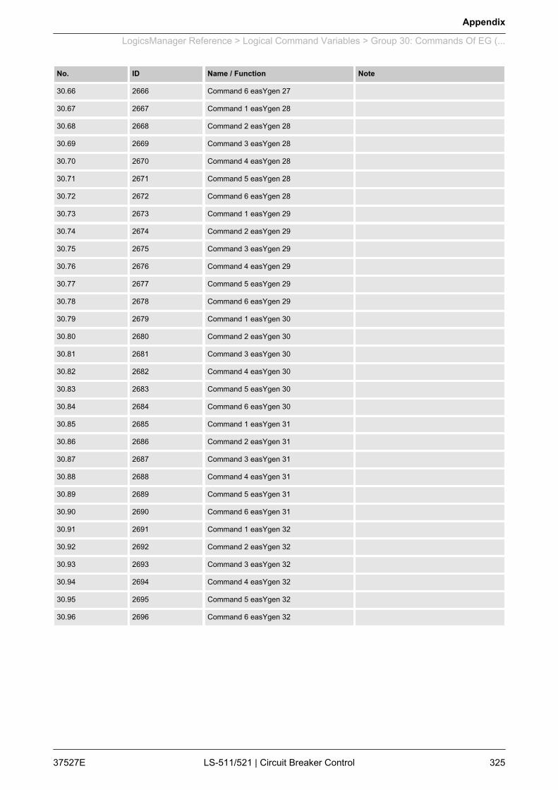
No. ID Name / Function Note
30.66 2666 Command 6 easYgen 27
30.67 2667 Command 1 easYgen 28
30.68 2668 Command 2 easYgen 28
30.69 2669 Command 3 easYgen 28
30.70 2670 Command 4 easYgen 28
30.71 2671 Command 5 easYgen 28
30.72 2672 Command 6 easYgen 28
30.73 2673 Command 1 easYgen 29
30.74 2674 Command 2 easYgen 29
30.75 2675 Command 3 easYgen 29
30.76 2676 Command 4 easYgen 29
30.77 2677 Command 5 easYgen 29
30.78 2678 Command 6 easYgen 29
30.79 2679 Command 1 easYgen 30
30.80 2680 Command 2 easYgen 30
30.81 2681 Command 3 easYgen 30
30.82 2682 Command 4 easYgen 30
30.83 2683 Command 5 easYgen 30
30.84 2684 Command 6 easYgen 30
30.85 2685 Command 1 easYgen 31
30.86 2686 Command 2 easYgen 31
30.87 2687 Command 3 easYgen 31
30.88 2688 Command 4 easYgen 31
30.89 2689 Command 5 easYgen 31
30.90 2690 Command 6 easYgen 31
30.91 2691 Command 1 easYgen 32
30.92 2692 Command 2 easYgen 32
30.93 2693 Command 3 easYgen 32
30.94 2694 Command 4 easYgen 32
30.95 2695 Command 5 easYgen 32
30.96 2696 Command 6 easYgen 32
Appendix
LogicsManager Reference > Logical Command Variables > Group 30: Commands Of EG (...
37527E LS-511/521 | Circuit Breaker Control 325

9.3.5 Factory Settings
Simple (function) Extended (configuration) Result
[00.0x] Flag {x}; {x} = 1 to 8
If TRUE, flag {x} becomes TRUE.
Deactivated by default.
FALSE
[00.15] External acknowledgment
If TRUE, all alarms are acknowledged from anexternal source.
TRUE once discrete input [DI 2] is energized.
dependent ondiscrete input[DI 2]
[00.16] Operation mode AUTOMATIC
If TRUE the unit changes into AUTOMATICoperating mode.
Deactivated by default.
Only available in operating mode "MAN" andapplication mode to .
FALSE
[00.17] Operation mode MANUAL
If TRUE the unit changes into MANUAL oper‐ating mode.
Deactivated by default.
Only available in operating mode "AUTO" andapplication mode to .
FALSE
[00.3x] Flag {y}; {x} = 0 to 7, {y} = 9 to 16
If TRUE, flag {y} becomes TRUE.
Deactivated by default.
FALSE
[00.38] Synchronization Mode CHECK
If TRUE, synchronization mode CHECK is ena‐bled.
Deactivated by default.
Only available in application mode to .
FALSE
[00.39] Synchronization Mode PERM
Functions
Appendix
LogicsManager Reference > Factory Settings
37527ELS-511/521 | Circuit Breaker Control326
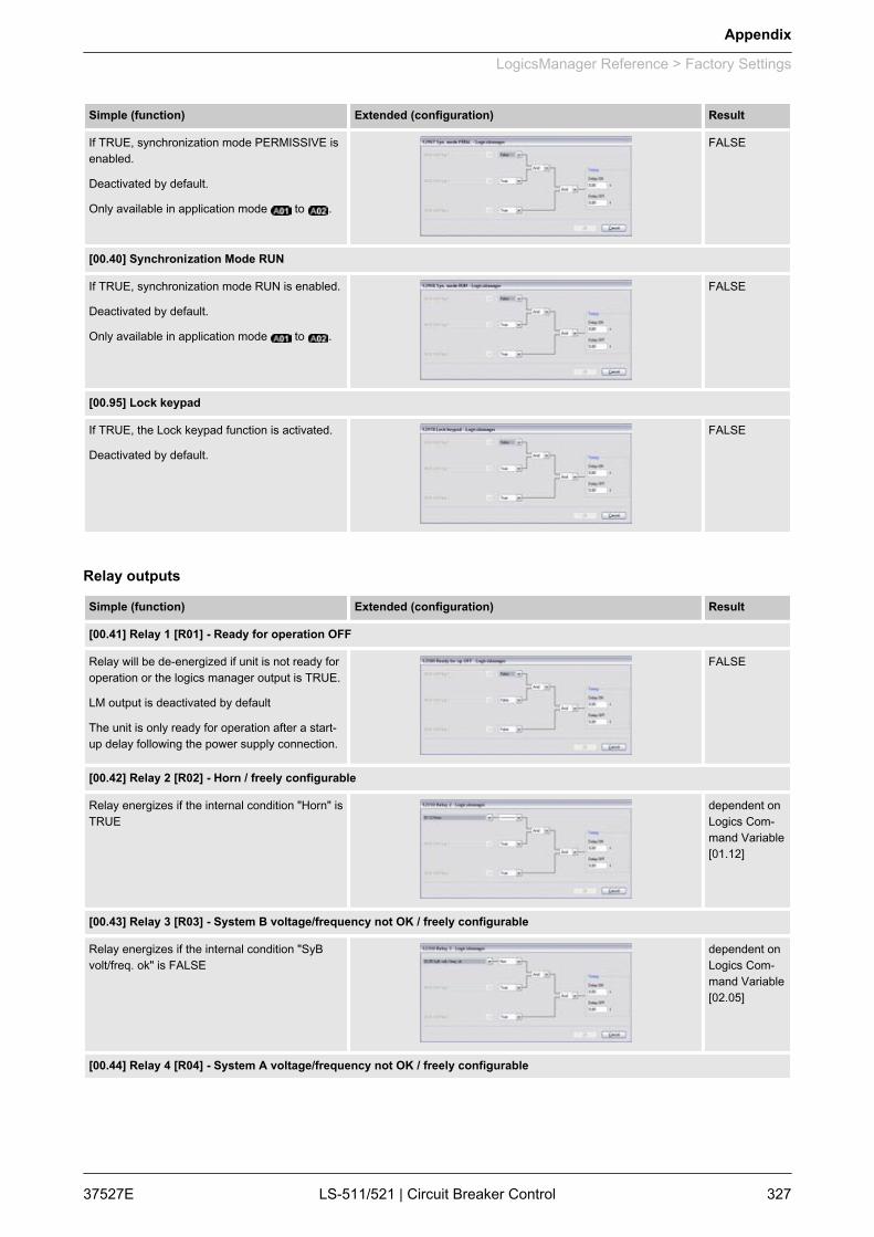
Simple (function) Extended (configuration) Result
If TRUE, synchronization mode PERMISSIVE isenabled.
Deactivated by default.
Only available in application mode to .
FALSE
[00.40] Synchronization Mode RUN
If TRUE, synchronization mode RUN is enabled.
Deactivated by default.
Only available in application mode to .
FALSE
[00.95] Lock keypad
If TRUE, the Lock keypad function is activated.
Deactivated by default.
FALSE
Simple (function) Extended (configuration) Result
[00.41] Relay 1 [R01] - Ready for operation OFF
Relay will be de-energized if unit is not ready foroperation or the logics manager output is TRUE.
LM output is deactivated by default
The unit is only ready for operation after a start-up delay following the power supply connection.
FALSE
[00.42] Relay 2 [R02] - Horn / freely configurable
Relay energizes if the internal condition "Horn" isTRUE
dependent onLogics Com‐mand Variable[01.12]
[00.43] Relay 3 [R03] - System B voltage/frequency not OK / freely configurable
Relay energizes if the internal condition "SyBvolt/freq. ok" is FALSE
dependent onLogics Com‐mand Variable[02.05]
[00.44] Relay 4 [R04] - System A voltage/frequency not OK / freely configurable
Relay outputs
Appendix
LogicsManager Reference > Factory Settings
37527E LS-511/521 | Circuit Breaker Control 327
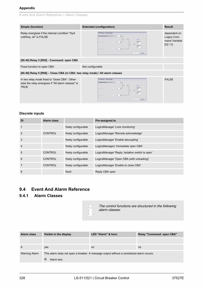
Simple (function) Extended (configuration) Result
Relay energizes if the internal condition "SyAvolt/freq. ok" is FALSE
dependent onLogics Com‐mand Variable[02.11]
[00.45] Relay 5 [R05] - Command: open CBA
Fixed function to open CBA Not configurable
[00.46] Relay 6 [R06] – Close CBA (in CBA: two relay mode) / All alarm classes
In two relay mode fixed to "close CBA". Other‐wise the relay energizes if "All alarm classes" isTRUE
FALSE
DI Alarm class Pre-assigned to
1 freely configurable LogicsManager 'Lock monitoring'
2 CONTROL freely configurable LogicsManager 'Remote acknowledge'
3 freely configurable LogicsManager 'Enable decoupling'
4 freely configurable LogicsManager) 'Immediate open CBA'
5 CONTROL freely configurable LogicsManager 'Reply: Isolation switch is open'
6 CONTROL freely configurable LogicsManager 'Open CBA (with unloading)'
7 CONTROL freely configurable LogicsManager 'Enable to close CBA'
8 fixed Reply CBA open
9.4 Event And Alarm Reference9.4.1 Alarm Classes
The control functions are structured in the followingalarm classes:
Alarm class Visible in the display LED "Alarm" & horn Relay "Command: open CBA"
A yes no no
Warning Alarm This alarm does not open a breaker. A message output without a centralized alarm occurs:
n Alarm text.
Discrete inputs
Appendix
Event And Alarm Reference > Alarm Classes
37527ELS-511/521 | Circuit Breaker Control328
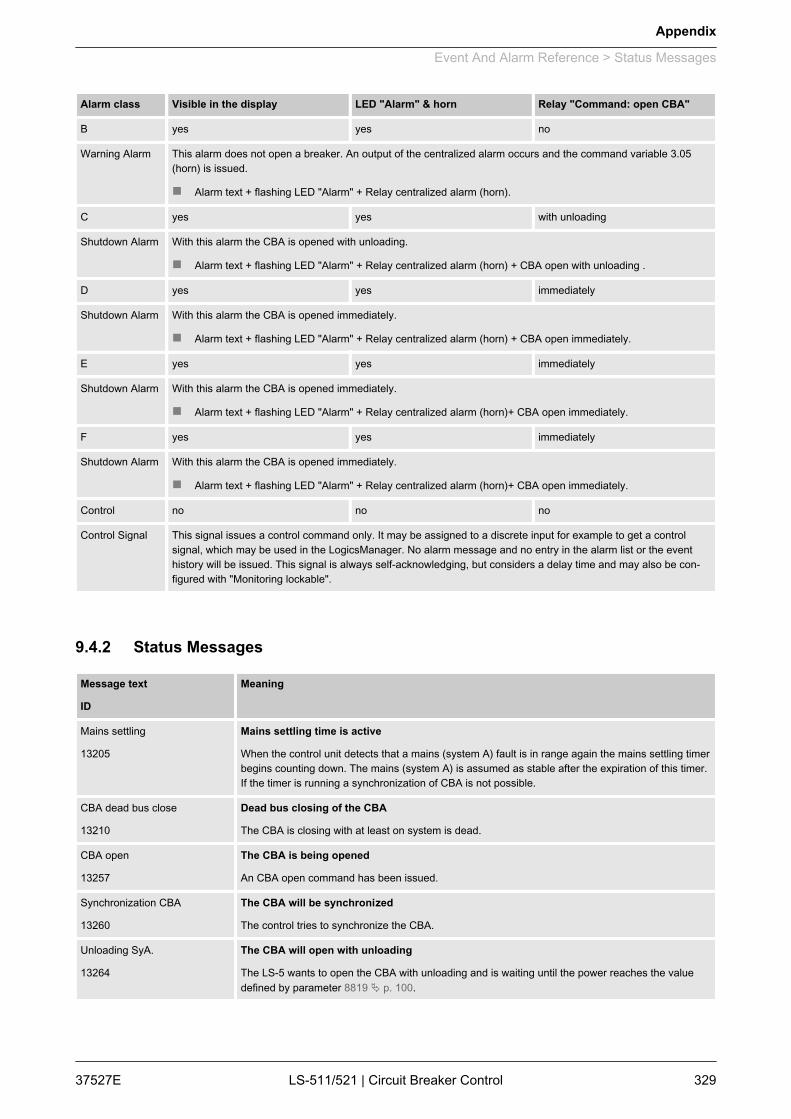
Alarm class Visible in the display LED "Alarm" & horn Relay "Command: open CBA"
B yes yes no
Warning Alarm This alarm does not open a breaker. An output of the centralized alarm occurs and the command variable 3.05(horn) is issued.
n Alarm text + flashing LED "Alarm" + Relay centralized alarm (horn).
C yes yes with unloading
Shutdown Alarm With this alarm the CBA is opened with unloading.
n Alarm text + flashing LED "Alarm" + Relay centralized alarm (horn) + CBA open with unloading .
D yes yes immediately
Shutdown Alarm With this alarm the CBA is opened immediately.
n Alarm text + flashing LED "Alarm" + Relay centralized alarm (horn) + CBA open immediately.
E yes yes immediately
Shutdown Alarm With this alarm the CBA is opened immediately.
n Alarm text + flashing LED "Alarm" + Relay centralized alarm (horn)+ CBA open immediately.
F yes yes immediately
Shutdown Alarm With this alarm the CBA is opened immediately.
n Alarm text + flashing LED "Alarm" + Relay centralized alarm (horn)+ CBA open immediately.
Control no no no
Control Signal This signal issues a control command only. It may be assigned to a discrete input for example to get a controlsignal, which may be used in the LogicsManager. No alarm message and no entry in the alarm list or the eventhistory will be issued. This signal is always self-acknowledging, but considers a delay time and may also be con‐figured with "Monitoring lockable".
9.4.2 Status Messages
Message text
ID
Meaning
Mains settling
13205
Mains settling time is active
When the control unit detects that a mains (system A) fault is in range again the mains settling timerbegins counting down. The mains (system A) is assumed as stable after the expiration of this timer.If the timer is running a synchronization of CBA is not possible.
CBA dead bus close
13210
Dead bus closing of the CBA
The CBA is closing with at least on system is dead.
CBA open
13257
The CBA is being opened
An CBA open command has been issued.
Synchronization CBA
13260
The CBA will be synchronized
The control tries to synchronize the CBA.
Unloading SyA.
13264
The CBA will open with unloading
The LS-5 wants to open the CBA with unloading and is waiting until the power reaches the valuedefined by parameter 8819 Ä p. 100.
Appendix
Event And Alarm Reference > Status Messages
37527E LS-511/521 | Circuit Breaker Control 329
Message text
ID
Meaning
Synch. PERMISSIVE
13265
Synchronization mode Permissive (twinckling)
Synchronization mode is set to Permissive (parameter 5728 Ä p. 115)
Synch. CHECK
13266
Synchronization mode Check (twinckling)
Synchronization mode is set to Check (parameter 5728 Ä p. 115)
Synch. OFF
13267
Synchronization mode Off (twinckling)
Synchronization mode is set to Off (parameter 5728 Ä p. 115)
Syn. mains close CBA
13279
Synchronous mains close CBA
The LS-5 has detected that System A and System B are connected to mains and is closing the CBAaccording to parameters 8820 Ä p. 109, 8821 Ä p. 110 and 8822 Ä p. 110.
Syn. segm. close CBA
13286
Synchronous segment close CBA
The LS-5 has detected that System A and System B are already alternatively connected and isclosing the CBA according to parameters 8852 Ä p. 110, 8821 Ä p. 110 and 8822 Ä p. 110.
CBA request
13280
CBA request
There is a command to open or close the CBA, but the execution is already blocked by the priorityof a breaker command off another LS-5/GCB or the LS-5 is still arbitrating the priority.
9.4.3 Event HistoryThe event history is a 300 entry FIFO (First In/First Out) memoryfor logging alarm events and operation states of the unit. As newevent messages are entered into the history, the oldest messagesare deleted once 300 events have occurred.For additional information refer to Ä Chapter 5 “Operation”on page 139.
1.Make sure to have set the appropriate code levelto reset the event history.If you have not entered the correct password forthe required code level, the parameters for reset‐ting the event history are not available (for addi‐tional information refer to Ä Chapter 4.1.5 “Pass‐word System” on page 69).
2. Reset the event history by setting the parameter "Clear even‐tlog" (parameter 1706 Ä p. 69) to "Yes" via the front panel.
ð The complete event history is now being cleared.
General notes
Resetting event history
Appendix
Event And Alarm Reference > Event History
37527ELS-511/521 | Circuit Breaker Control330
9.4.3.1 Event Messages
Message text
ID
Meaning
AUTO mode
14353
Auto mode became active
MAN mode
14355
Manual mode became active
Feedback CBA open
14700
Reply CBA open became active
Feedback CBA close
14701
CBA close (reply CBA open became )
14724
System A is ok
System A became ok (Voltage and frequency in range)
System B is ok
14727
System B became ok (Voltage and frequency in range)
Close command CBA
14730
CBA close command became active
Open command CBA
14731
CBA open command became active
Start up power
14778
Power up cycle happened
9.4.3.2 Alarm Messages
For a detailed description of the monitoring functions,which trigger the alarm messages, refer toÄ Chapter 4.3 “Configure Monitoring” on page 74.
Message text
ID
Meaning
Bat. overvoltage 1
10007
Battery overvoltage, limit value 1
The battery voltage has exceeded the limit value 1 for battery overvoltage for at least the configuredtime and did not fall below the value of the hysteresis.
Bat. overvoltage 2
10008
Battery overvoltage, limit value 2
The battery voltage has exceeded the limit value 2 for battery overvoltage for at least the configuredtime and did not fall below the value of the hysteresis.
Bat. undervoltage 1
10005
Battery undervoltage, limit value 1
The battery voltage has fallen below the limit value 1 for battery undervoltage for at least the config‐ured time and has not exceeded the value of the hysteresis.
Appendix
Event And Alarm Reference > Event History > Alarm Messages
37527E LS-511/521 | Circuit Breaker Control 331

Message text
ID
Meaning
Bat. undervoltage 2
10006
Battery undervoltage, limit value 2
The battery voltage has fallen below the limit value 2 for battery undervoltage for at least the config‐ured time and has not exceeded the value of the hysteresis.
CANopen Interface 1
10087
Interface alarm CANopen on CAN bus 1
No Receive Process Data Object (RPDO) is received within the configured time.
EEPROM failure
1714
The EEPROM checksum is corrupted
The EEPROM check at startup has resulted a defective EEPROM.
SyB. phase rotation
3955
System B rotating field
The system A rotating field does not correspond with the configured direction.
SyA. decoupling
3114
System A decoupling is initiated
One or more monitoring function(s) considered for the system A decoupling functionality has trig‐gered.
SyA. overfreq. 1
2862
System A overfrequency, limit value 1
The system A frequency has exceeded the limit value 1 for system A overfrequency for at least theconfigured time and did not fall below the value of the hysteresis.
SyA. overfreq. 2
2863
System A overfrequency, limit value 2
The system A frequency has exceeded the limit value 2 for system A overfrequency for at least theconfigured time and did not fall below the value of the hysteresis. Triggering this monitoring functioncauses the mains decoupling function to trigger.
SyA. overvoltage 1
2962
System A overvoltage, limit value 1
The system A voltage has exceeded the limit value 1 for system A overvoltage for at least the con‐figured time and did not fall below the value of the hysteresis.
SyA. overvoltage 2
2963
System A overvoltage, limit value 2
The system A voltage has exceeded the limit value 2 for system A overvoltage for at least the con‐figured time and did not fall below the value of the hysteresis. Triggering this monitoring functioncauses the mains decoupling function to trigger.
SyA. phase shift
3057
System A phase shift
A system A phase shift, which has exceeded the configured limit, has occurred. Triggering thismonitoring function causes the system A decoupling function to trigger.
SyA. underfreq. 1
2912
System A underfrequency, limit value 1
The system A frequency has fallen below the limit value 1 for system A underfrequency for at leastthe configured time and has not exceeded the value of the hysteresis.
SyA underfreq. 2
2913
System A underfrequency, limit value 2
The system A frequency has fallen below the limit value 2 for system A underfrequency for at leastthe configured time and has not exceeded the value of the hysteresis. Triggering this monitoringfunction causes the mains decoupling function to trigger.
SyA. undervoltage 1
3012
System A undervoltage, limit value 1
The system A voltage has fallen below the limit value 1 for system A undervoltage for at least theconfigured time and has not exceeded the value of the hysteresis.
SyA. undervoltage 2
3013
System A undervoltage, limit value 2
The system A voltage has fallen below the limit value 2 for system A undervoltage for at least theconfigured time and has not exceeded the value of the hysteresis. Triggering this monitoring func‐tion causes the mains decoupling function to trigger.
Appendix
Event And Alarm Reference > Event History > Alarm Messages
37527ELS-511/521 | Circuit Breaker Control332
Message text
ID
Meaning
CBA fail to close
2623
CBA failed to close
The LS-5 has attempted to close the CBA the configured maximum number of attempts and failed.The LS-5 will continue to attempt to close the CBA as long as the conditions for closing the CBA arefulfilled.
CBA fail to open
2624
Failed CBA open
The LS-5 is still receiving the reply CBA closed after the CBA open monitoring timer has expired.
CBA syn. timeout
3074
CBA synchronization time exceeded
The LS-5 has failed to synchronize the CBA within the configured synchronization time.
Missing LS5
4064
Missing LS-5 members detected
The LS-5 has detected that the number of available units at CAN does not correspond with the con‐figured application mode.
SyA. phase rotation
3975
System A rotating field
The system A rotating field does not correspond with the configured direction.
Ph.rotation mismatch
2944
System A/System B phase rotation different
System A or System B has different rotating fields. A CB closure is blocked.
SyA. df/dt
3106
System A df/dt (ROCOF)
A system A df/dt, which has exceeded the configured limit, has occurred. Triggering this monitoringfunction causes the system A decoupling function to trigger.
SyA. volt. asymmetry
3928
System A voltage asymmetry
For at least the delay time without interruption.
SyA. volt. incr.
8834
System A voltage increase
The limit for voltage increase is reached or exceeded.
SyA. time-dep. voltage
4958
System A time-dependent voltage
The measured voltage falls below/exceeds the configured criteria.
QV monitoring 1
3288
QV monitoring, delay time 1
The system A reactive power has exceeded the limit for at least the configured delay time 1.
QV monitoring 2
3289
QV monitoring, delay time 2
The system A reactive power has exceeded the limit for at least the configured delay time 2.
CBA unload mismatch
8838
CBA unloading mismatch
While unloading CBA the defined limit of load is not reached in the defined time.
Discrete input {x} Discrete input {x}, energized / de-energized
The actual state of the monitored discrete input is energized / de-energized (depending on the con‐figuration) for at least the configured time. This text may be assigned customer defined. The text inangular brackets is the default text.
Refer to Ä “ Message IDs for discrete inputs” on page 333.
Discrete input # 1 2 3 4 5 6 7
Message ID 10600 10601 10602 10603 10604 10605 10607
Message IDs for discrete inputs
Appendix
Event And Alarm Reference > Event History > Alarm Messages
37527E LS-511/521 | Circuit Breaker Control 333

9.5 Additional Application Information9.5.1 Synchronization Of System A and System B
The table below gives an overview about the synchronization ofsystems A with system B.Drawing index:n Yes: The synchronization is executedn blocked: The synchronization is blockedn n.a.: not applicable (not possible to configure)n Not allowed (*1:
The neutral could not be located in the middle of the delta vol‐tages
n Not allowed (*2:These constellations are not applicable
Fig. 132: LS-5 Synchronization Table - Two Systems A-B
Synchronization Table
Appendix
Additional Application Infor... > Synchronization Of System ...
37527ELS-511/521 | Circuit Breaker Control334
10 Glossary And List Of AbbreviationsCB Circuit BreakerCL Code LevelCT Current TransformerDI Discrete InputDO Discrete (Relay) OutputECU Engine Control UnitFMI Failure Mode IndicatorGCB Generator Circuit BreakerGGB Generator Group BreakerI CurrentIOP Isolated Operation in ParallelLDSS Load-Dependent Start/Stop operationMCB Mains Circuit BreakerMOP Mains Operation in ParallelMPU Magnetic Pickup UnitN.C. Normally Closed (break) contactN.O. Normally Open (make) contactOC Occurrence CountP Real powerP/N Part NumberPF Power FactorPID Proportional Integral Derivative controllerPLC Programmable Logic ControlPT Potential (Voltage) TransformerQ Reactive powerS Apparent powerS/N Serial NumberSPN Suspect Parameter NumberV Voltage
Glossary And List Of Abbreviations
37527E LS-511/521 | Circuit Breaker Control 335

Glossary And List Of Abbreviations
37527ELS-511/521 | Circuit Breaker Control336

11 IndexAAlarms................................................................ 102BBattery
Monitoring............................................. 104, 105CCAN
Monitoring..................................................... 103CBA...................................................................... 98
Unload Mismatch.......................................... 100Contact person..................................................... 16Customer Service................................................. 16IIntended use........................................................ 16MMains
Voltage Phase Rotation.................................. 97PPersonnel............................................................. 17Phase Rotation
System A / System B.................................... 101
Protective equipment........................................... 21SService................................................................. 16Symbols
in the instructions............................................ 14Synchronization.................................................. 334System A
Overfrequency................................................ 78Overvoltage..................................................... 80Phase Rotation............................................... 88Underfrequency.............................................. 79Undervoltage................................................... 82Voltage asymmetry......................................... 90
System BOperating Voltage / Frequency....................... 96
UUse....................................................................... 16WWarranty............................................................... 16
Index
37527E LS-511/521 | Circuit Breaker Control 337

37527ELS-511/521 | Circuit Breaker Control338


Woodward GmbHHandwerkstrasse 29 - 70565 Stuttgart - GermanyPhone +49 (0) 711 789 54-510Fax +49 (0) 711 789 [email protected]