Welcome message from author
This document is posted to help you gain knowledge. Please leave a comment to let me know what you think about it! Share it to your friends and learn new things together.
Transcript

$&(5 3'3
:,'( 3/$60$ ',$3/$<
86(56 0$18$/
)($785(6
7KLV GLVSOD\ KDV D SODVPD GLVSOD\ SDQHO DQG LV RQO\
FP GHHS :LWK LWV KLJK LPDJH TXDOLW\ DQG
SHUIRUPDQFH LW LV SHUIHFWO\ VXLWHG WR PXOWLPHGLD
DSSOLFDWLRQV
! &DQ UHFHLYH D YDULHW\ RI LQSXW VLJQDOV
! 9LGHR LQSXW PRGH
! 5*% LQSXW PRGH
! 3RZHU 0DQDJHPHQW )XQFWLRQ
! 5HPRWH 0RXVH )XQFWLRQ
Ù
English 1
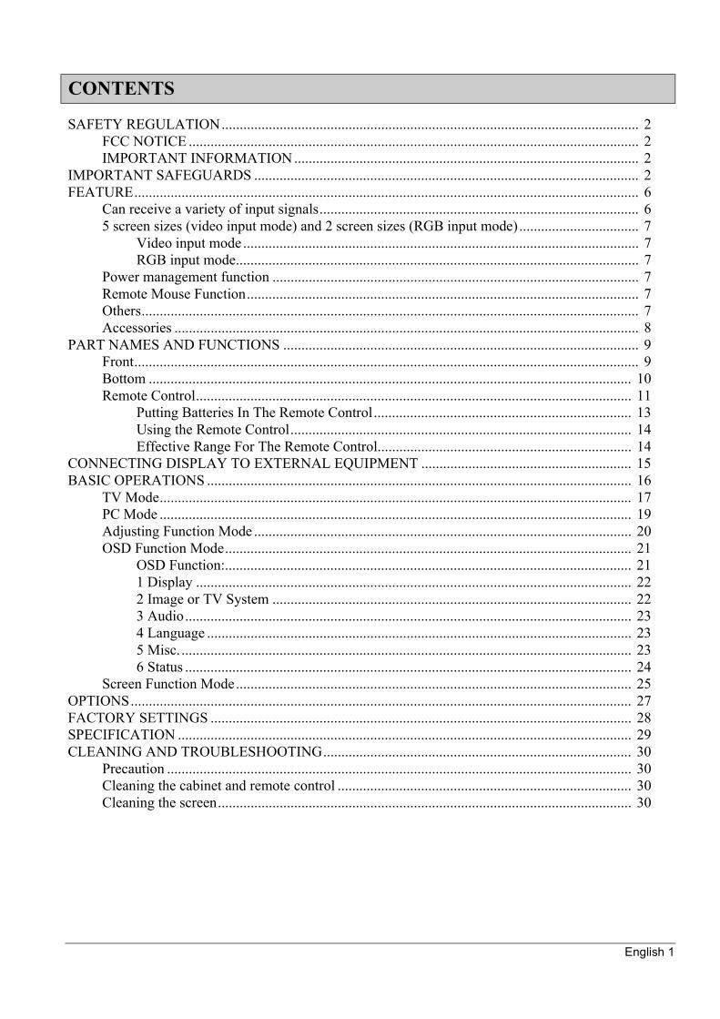
SAFETY REGULATION................................................................................................................... 2FCC NOTICE ............................................................................................................................ 2IMPORTANT INFORMATION ............................................................................................... 2
IMPORTANT SAFEGUARDS .......................................................................................................... 2FEATURE........................................................................................................................................... 6
Can receive a variety of input signals........................................................................................ 65 screen sizes (video input mode) and 2 screen sizes (RGB input mode)................................. 7
Video input mode ............................................................................................................. 7RGB input mode............................................................................................................... 7
Power management function ..................................................................................................... 7Remote Mouse Function............................................................................................................ 7Others......................................................................................................................................... 7Accessories ................................................................................................................................ 8
PART NAMES AND FUNCTIONS .................................................................................................. 9Front........................................................................................................................................... 9Bottom ..................................................................................................................................... 10Remote Control........................................................................................................................ 11
Putting Batteries In The Remote Control....................................................................... 13Using the Remote Control.............................................................................................. 14Effective Range For The Remote Control...................................................................... 14
CONNECTING DISPLAY TO EXTERNAL EQUIPMENT .......................................................... 15BASIC OPERATIONS ..................................................................................................................... 16
TV Mode.................................................................................................................................. 17PC Mode .................................................................................................................................. 19Adjusting Function Mode ........................................................................................................ 20OSD Function Mode................................................................................................................ 21
OSD Function:................................................................................................................ 211 Display ........................................................................................................................ 222 Image or TV System ................................................................................................... 223 Audio........................................................................................................................... 234 Language ..................................................................................................................... 235 Misc. ............................................................................................................................ 236 Status ........................................................................................................................... 24
Screen Function Mode............................................................................................................. 25OPTIONS.......................................................................................................................................... 27FACTORY SETTINGS .................................................................................................................... 28SPECIFICATION ............................................................................................................................. 29CLEANING AND TROUBLESHOOTING..................................................................................... 30
Precaution ................................................................................................................................ 30Cleaning the cabinet and remote control ................................................................................. 30Cleaning the screen.................................................................................................................. 30
CONTENTS
English 2
FCC NOTICEAcer PDP 7859: A Class A digital deviceThis equipment has been tested and found to comply with the limits for a Class A digital device, pursuant to part 15 of the FCC Rules. These limits are designed to provide reasonable protection against harmful interferences when the equipment is operated in a commercial environment. This equipment will generates and radiate radio frequency energy, if not installed and used in accordance with the instruction manual, may cause harmful interference to radio communications. Operation of this equipment in a residential area is likely to cause harmful interference in which case the user will be required to correct the interference at his own expense.
IMPORTANT INFORMATION
SAFETY REGULATION
WARNING: This is a Class A product. In a domestic environment this product may cause radio interference in which case the user may be required to take adequate measures.
WARNING: To Reduce The Risk Of Fire And Electric Shock, Do not Expose This Product To Rain Or Moisture.
IMPORTANT SAFEGUARDS

English 3
oil. ..
....

English 4
Electrical energy can perform many useful functions. This unit has been engineered and manufactured to assure your personal safety. But IMPROPER USE CAN RESULT IN POTENTIAL ELECTRICAL SHOCK OR FIRE HAZARD. In order not to defeat the safeguards incorporated into this product, observe the following basic rules for its installation, use and service. Please read these “Important Safeguards” carefully before use.
All the safety and operating instructions should be read before the product is operated.The safety and operating instructions should be retained for future reference.All warning on the product and in the operating instructions should be adhered to.All operating instructions should be followed.Unplug this product from the wall outlet before cleaning. Do not use liquid cleaners or aerosol cleaners. Use a damp cloth for cleaning.Do not use attachments not recommended by the product manufacturer as they may cause hazards.Do not use this product near water. Do not use immediately after moving from a low temperature to high temperature, as this causes condensation, which may result in fire, electric shock, or other hazards.Do not place this product on an unstable cart, stand, or table. The product may fall, causing serious injury to a child or adult, and serious damage to the product. The product should be mounted according to the manufacturer’s instructions, and should use a mount recommended by the manufacturer.
English 5
When the product is used on a cart, care should be taken to avoid quick stops, excessive force, and uneven surfaces that may cause the product and cart to overturn, damaging equipment or causing possible injury to the operator.Slots and openings in the cabinet are provided for ventilation. These ensure reliable operation of the product and protect it from overheating. These openings must not be blocked or covered. (The openings should never be blocked by placing the product on bed, sofa, rug, or other similar surface.) It should not be placed in a built-in installation such as a bookcase or rack unless proper ventilation is provided and the manufacturer’s instructions have been adhered to.)For proper ventilation, separate the product from other equipment, which may prevent ventilation and keep distance more than 10 cm.This product should be operated only from the type of power source indicated on the label. If you are not sure of the type of power supply to your home, consult your product dealer or local power company.This product is equipped with a three-wire plug. This plug will fit only into a grounded power outlet. If you are unable to insert the plug into the outlet, contact your electrician to install the proper outlet. Do not defeat the safety purpose of the grounded plug.Power-supply cords should be routed so that they are not likely to be walked on or pinched by items placed upon or against them. Pay particular attention to cords at doors, plugs, receptacles, and the point where they exit from the product. For added protection for this product during a lightening storm, or when it is left unattended and unused for long periods of time, unplug it from the wall outlet and disconnect the cable system. This will prevent damage to the product due to lightening and power line surges.Do not overload wall outlets, extension cords, or convenience receptacles on other equipment as this can result in a risk of fire or electric shock.Never push objects of any kind into this product through openings as they may touch dangerous voltage points or short out parts that could result in a fire or electric shock. Never spill liquid of any kind on the product.Do not attempt to service this product yourself as opening or removing covers may expose you to dangerous voltages and other hazards. Refer all service to qualified service personnel.Unplug this product from the wall outlet and refer service to qualified service personnel under the following conditions:a. When the power supply cord or plug is damaged.b. If liquid has been spilled, or objects have fallen on the product.c. If the product has been exposed to rain or water.d. If the product does not operate normally by following the operating instructions. Adjust only
those controls that are covered by the Operation Manual, as an improper adjustment of other controls may result in damage and will often require extensive work by a qualified technician to restore the product to its normal operation.
e. If the product has been dropped or damaged in any way.When the product exhibits a distinct change in performance—this indicates a need for service.When replacement parts are required, be sure the service technician has used replacement parts specified by the manufacturer or with same characteristics as the original part. Unauthorized substitutions may result in fire, electric shock, or other hazards.Upon completion of any service or repairs to this product, ask the service technician to perform safety checks to determine that the product is in proper operating condition.

English 6
The product should be placed more than one foot away from heat sources such as radiators, heat registers, stoves, and other products (including amplifiers) that produce heat.When connecting other products such as VCR’s, and personal computers, you should turn off the power of this product for protection against electric shock.Do not place combustibles behind the cooling fan. For example, cloth, paper, matches, aerosol cans or gas lighters the present special hazards when over heated.Use only the accessory cord designed for this product to prevent shock. The power supply voltage rating of this product is AC100-240V. The power cord attached conforms to the following power supply voltage. Use only the power cord designated by our dealer to ensure Safety and EMC.When it is used by other power supply voltage, power cable must be changed. Consult your product dealer.The power supply cord serves as a power disconnect device for plug able equipment. The socket outlet shall be installed near the equipment and shall be easily accessible.
This display has a plasma display panel and is only 10.6 cm deep. With its high image quality and performance, it is perfectly suited to multimedia applications.
Can receive a variety of input signalsIn addition to video, S-video, and RGB (D-SUB connector) signals, this display supports input of high-quality video signals such as DVD.The display is applicable to the following color television systems used worldwide: NTSC, SECAM, PAL-N, PAL-M.The display has a component video input terminal to receive signals from the DVD players as well as digital broadcasting signals (component video signals).
The display has an RGB input terminal to receive signals, including wide RGB signals*1, VGA, SVGA, and XGA*2.
FEATURE
*1 : With the optionally available graphics board, you can send wide RGB signals (852 x480) from your PC.
*2 : The refresh rate of 60, 70, 75, 85 Hz for XGA (1024 x 768) and those of 60, 70, and 75 Hz for SVGA (800 x 600) are supported.
English 7
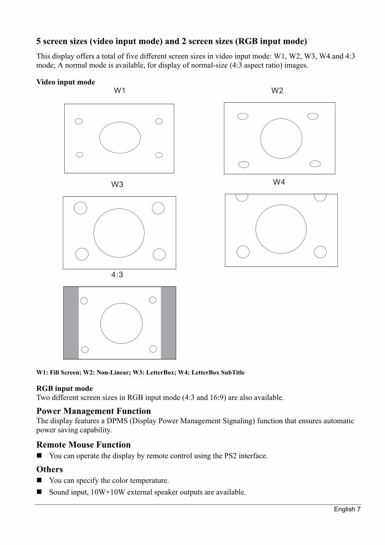
5 screen sizes (video input mode) and 2 screen sizes (RGB input mode)This display offers a total of five different screen sizes in video input mode: W1, W2, W3, W4.and 4:3 mode; A normal mode is available, for display of normal-size (4:3 aspect ratio) images.
Video input mode
W1: Fill Screen; W2: Non-Linear; W3: LetterBox; W4: LetterBox SubTitle
RGB input modeTwo different screen sizes in RGB input mode (4:3 and 16:9) are also available.
Power Management FunctionThe display features a DPMS (Display Power Management Signaling) function that ensures automatic power saving capability.
Remote Mouse FunctionYou can operate the display by remote control using the PS2 interface.
OthersYou can specify the color temperature.Sound input, 10W+10W external speaker outputs are available.
English 8
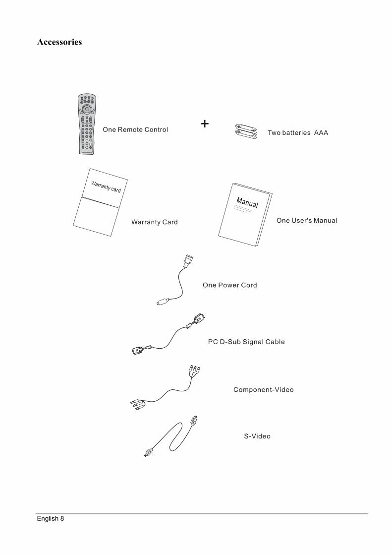
Accessories
English 9
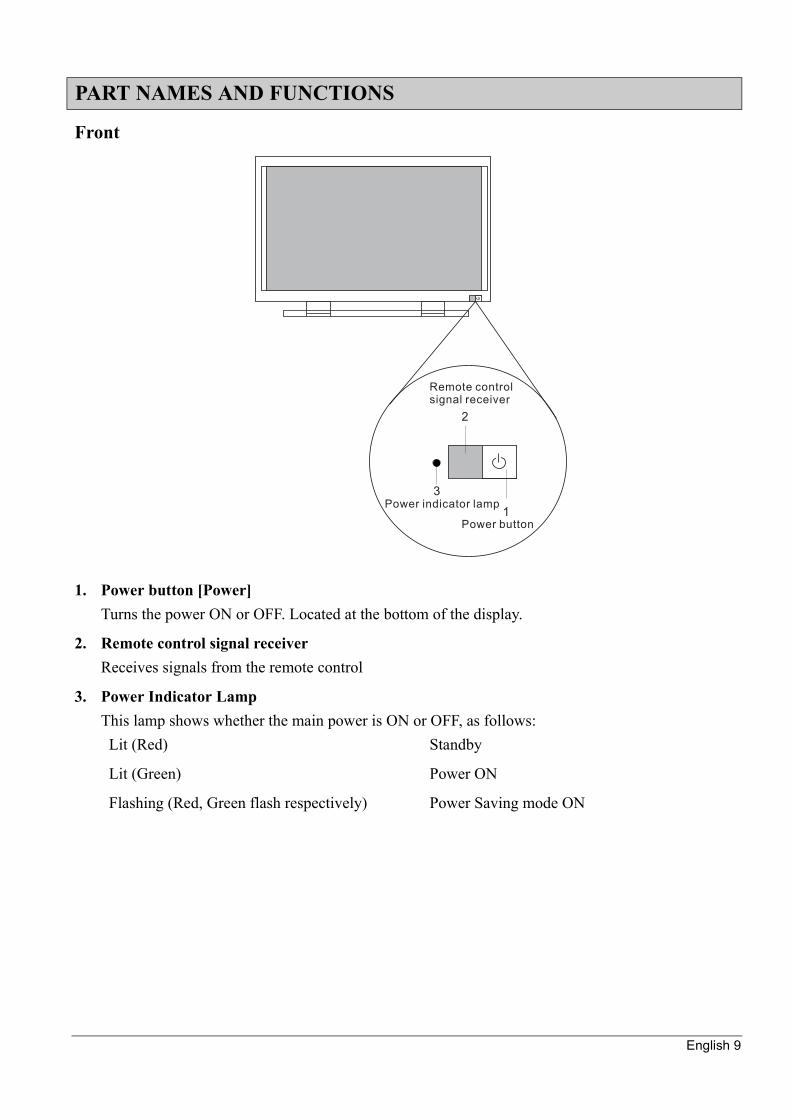
Front
1. Power button [Power]Turns the power ON or OFF. Located at the bottom of the display.
2. Remote control signal receiverReceives signals from the remote control
3. Power Indicator LampThis lamp shows whether the main power is ON or OFF, as follows:
PART NAMES AND FUNCTIONS
Lit (Red) Standby
Lit (Green) Power ON
Flashing (Red, Green flash respectively) Power Saving mode ON
English 10
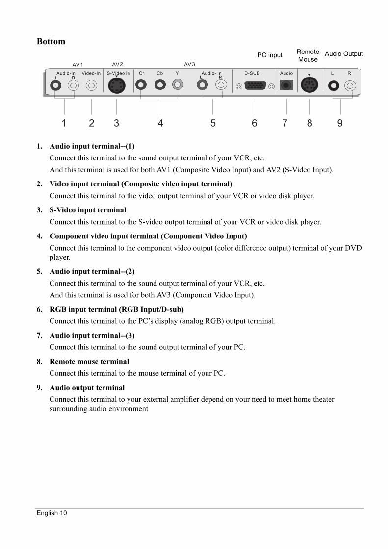
Bottom
1. Audio input terminal--(1)Connect this terminal to the sound output terminal of your VCR, etc.And this terminal is used for both AV1 (Composite Video Input) and AV2 (S-Video Input).
2. Video input terminal (Composite video input terminal)Connect this terminal to the video output terminal of your VCR or video disk player.
3. S-Video input terminalConnect this terminal to the S-video output terminal of your VCR or video disk player.
4. Component video input terminal (Component Video Input)Connect this terminal to the component video output (color difference output) terminal of your DVD player.
5. Audio input terminal--(2)Connect this terminal to the sound output terminal of your VCR, etc.And this terminal is used for both AV3 (Component Video Input).
6. RGB input terminal (RGB Input/D-sub)Connect this terminal to the PC’s display (analog RGB) output terminal.
7. Audio input terminal--(3)Connect this terminal to the sound output terminal of your PC.
8. Remote mouse terminalConnect this terminal to the mouse terminal of your PC.
9. Audio output terminalConnect this terminal to your external amplifier depend on your need to meet home theater surrounding audio environment
AV2 AV 3AV1
Audio-In Video-In S-Video In Cr Cb Y Audio- In D-SUB Audio L RL RL R
1 2 3 4 5 6 7 8 9
PC input Remote Mouse
Audio Output
English 11
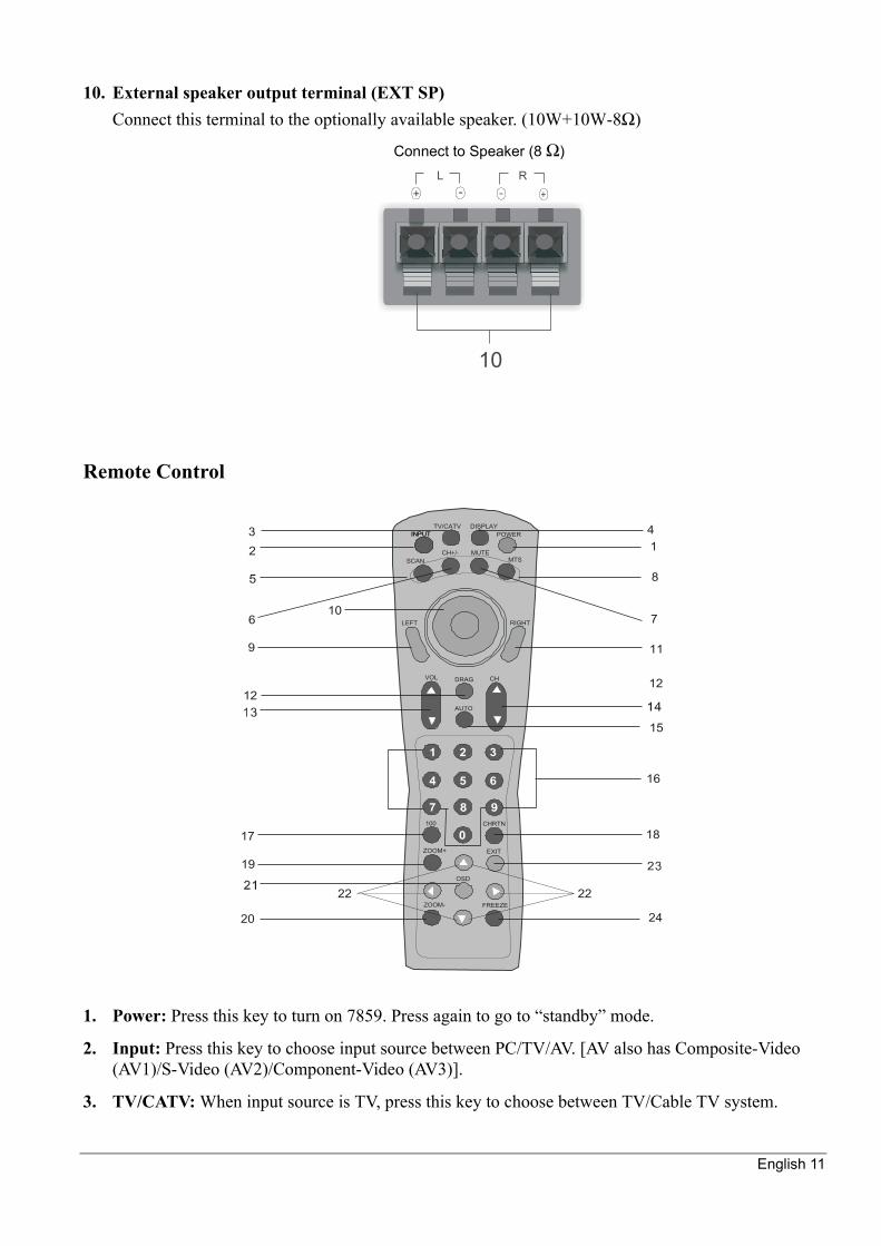
10. External speaker output terminal (EXT SP)Connect this terminal to the optionally available speaker. (10W+10W-8Ω)
Remote Control
1. Power: Press this key to turn on 7859. Press again to go to “standby” mode.
2. Input: Press this key to choose input source between PC/TV/AV. [AV also has Composite-Video (AV1)/S-Video (AV2)/Component-Video (AV3)].
3. TV/CATV: When input source is TV, press this key to choose between TV/Cable TV system.
Connect to Speaker (8 Ω)
1 2 3
4 5 6
12
3 4
7
8
10
11
12
9
6
15
16
12
17 18
19
20
22 22
24
INPUT POWER
SCANCH+/- MUTE
MTS
CHVOL DRAG
AUTO
CHRTN
EXIT
FREEZE
ZOOM+
ZOOM-
OSD
100
RIGHTLEFT
TV/CATV DISPLAYINPUT
English 12
4. Display: Press this key to turn on the TV channel message shown on the screen. Press again to turn off.
5. Scan: Press this key to auto scan all channels the TV/CATV system provides.
6. CH +/-: Press this key to add the current TV channel. Press again to erase the current TV channel.
7. Mute: Press this key to quiet the sound system. Press again to activate the sound system.
8. MTS: Press this key to choose between Mono/SAP/Stereo.
9. LM (Left Mouse button): Function as left mouse button of PC.
10. Direction: Press the direction you want. Function as mouse rolling ball
11. RM (Right Mouse button): Function as right mouse button of PC.
12. Mouse Drag: This key simulates the mouse drag function as in PC system. Press this key to make mouse drag function (as if right mouse button is pressed continuously). Press again to back to normal situation.
13. Volume : Use these two hot keys to adjust volume straight and select sub-menus while in OSD mode.
14. Channel : Use these two hot keys to select channel straight (reserved) in TV mode.
15. Auto: Press this key to auto adjust phase, clock, H/V position in PC mode or to auto detect video system in TV/AV mode.
16. Number Keys: Including number “0,1,2,3,4,5,6,7,8,9”. Select the channel number to enter it. (When the channel is only one digit, you need to press ‘0’ before it.)
17. +100: When the channel number has three digits, press this key to input the first one digit.
18. CH RTN: Press this key to jump between two channels.
19. Zoom +: Press this key to enlarge the screen.
20. Zoom -: Press this key to minify the screen.
21. OSD: Press this key to pop up the OSD menu.
22. (Left/ Right/ Up/ Down key.): Use the keys to adjust the OSD.
23. OSD ESC: Press this key to exit OSD menu directly.
24. Freeze: Press this key to hold on the screen (the video source still runs). Press again to continue.
English 13
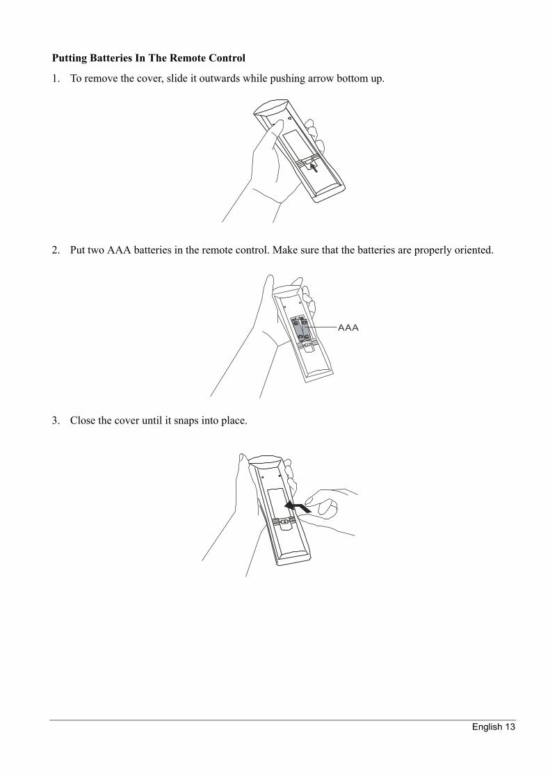
Putting Batteries In The Remote Control
1. To remove the cover, slide it outwards while pushing arrow bottom up.
2. Put two AAA batteries in the remote control. Make sure that the batteries are properly oriented.
3. Close the cover until it snaps into place.
-
-

English 14
Using the Remote Control
Effective Range For The Remote Control
Point the remote control at the display’s signal receiver when using it.So, make sure that there are no obstacles between the remote control and the display’s signal receiver.
To prevent malfunction, be sure not to apply any form of serve shock to the remote control. And to prevent malfunction or deformation, be sure not to allow the remote control to become wet; also keep it away from hot locations or heating equipment.
Be sure not to clean the remote control using a cloth dampened in any volatile solvent, such as benzene or thinner.
English 15
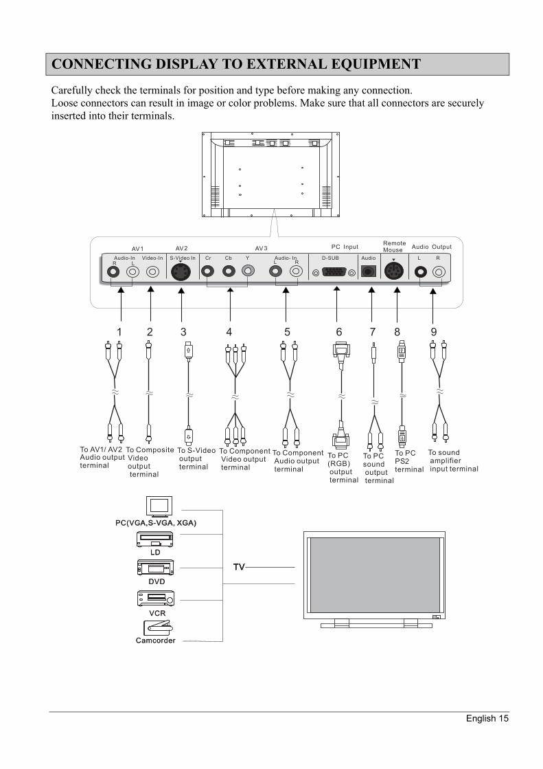
Carefully check the terminals for position and type before making any connection.Loose connectors can result in image or color problems. Make sure that all connectors are securely inserted into their terminals.
CONNECTING DISPLAY TO EXTERNAL EQUIPMENT
TVTVTVTV
LD
PC(VCA,S-VGA, XGA)
DVD
VCR
Camcorder
LD
PC(VGA,S-VGA, XGA)
DVD
VCR
Camcorder

English 16
Turning On/Off The Power
BASIC OPERATIONS
Turning On The Power Turning Off The Power
Press the power bottom on the remote control Press when the power is ON
Adjusting The Input Mode
Press this key to choose input source between PC/TV/AV. [AV also has Composite-Video (AV1)/S-Video (AV2)/Component-Video (AV3)]. And press again to work as “enter” function.
Each time you press, a different input mode appears. The sequence is as follows:
PC: Display images from equipment connected to the PC RGB terminalAV1: Display images from equipment connected to the Composite Video terminalAV2: Display images from equipment connected to the S-Video terminalAV3: Display images from equipment connected to the Component Video input terminalTV: Display images only when a TV tuner card is connected to the cable TV terminal.
INPUT POWER
SCANCH+/- MUTE
MTS
CHVOL DRAG
AUTO
CHRTN
EXIT
FREEZE
ZOOM+
ZOOM-
OSD
100
RIGHTLEFT
TV/CATV DISPLAYINPUTPOWER
1 2 31 2 31 2 31 2 3
4 5 64 5 64 5 64 5 6
00
7 8 97 8 97 8 97 8 9
INPUTINPUT POWERPOWER
SCANSCANCH+/-CH+/- MUTEMUTE
MTSMTS
CHCHVOLVOL DRAGDRAG
AUTOAUTO
CHRTNCHRTN
EXITEXIT
FREEZEFREEZE
ZOOM+ZOOM+
ZOOM-ZOOM-
OSDOSD
100100
RIGHTRIGHTLEFTLEFT
TV/CATVTV/CATV DISPLAYDISPLAYINPUTINPUT
INPUTINPUT POWER
SCANCH+/- MUTE
MTS
CHVOL DRAG
AUTO
CHRTN
EXIT
FREEZE
ZOOM+
ZOOM-
OSD
100
RIGHTLEFT
TV/CATV DISPLAYINPUT
English 17
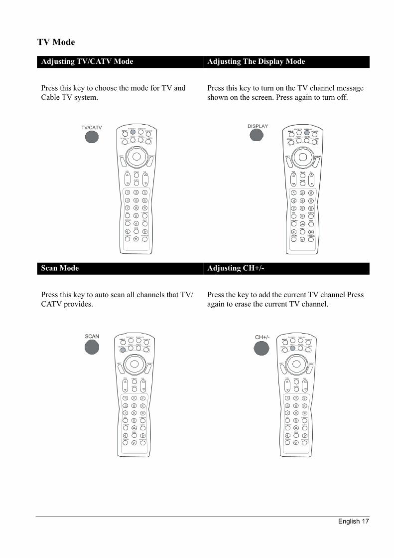
TV Mode
Adjusting TV/CATV Mode Adjusting The Display Mode
Press this key to choose the mode for TV and Cable TV system.
Press this key to turn on the TV channel message shown on the screen. Press again to turn off.
Scan Mode Adjusting CH+/-
Press this key to auto scan all channels that TV/CATV provides.
Press the key to add the current TV channel Press again to erase the current TV channel.
INPUT POWER
SCANCH+/- MUTE
MTS
CHVOL DRAG
AUTO
CHRTN
EXIT
FREEZE
ZOOM+
ZOOM-
OSD
100
RIGHTLEFT
TV/CATV DISPLAYINPUT
TV/CATV DISPLAYINPUTINPUT POWERPOWER
SCANSCANCH+/-CH+/- MUTEMUTE
MTSMTS
CHCHVOLVOL DRAGDRAG
AUTOAUTO
CHRTNCHRTN
EXITEXIT
FREEZEFREEZE
ZOOM+ZOOM+
ZOOM-ZOOM-
OSDOSD
100100
RIGHTRIGHTLEFTLEFT
TV/CATVTV/CATV DISPLAYDISPLAYINPUTINPUT
SCANINPUT POWER
SCANCH+/- MUTE
MTS
CHVOL DRAG
AUTO
CHRTN
EXIT
FREEZE
ZOOM+
ZOOM-
OSD
100
RIGHTLEFT
TV/CATV DISPLAYINPUT CH+/-
INPUT POWER
SCANCH+/- MUTE
MTS
CHVOL DRAG
AUTO
CHRTN
EXIT
FREEZE
ZOOM+
ZOOM-
OSD
100
RIGHTLEFT
TV/CATV DISPLAYINPUT

English 18
Mute Function MTS Function
Press the key to quiet the sound system. Press again to activate the sound system.
Press this key to choose between Mono/SAP/Stereo
Number Key Function +100 Function
Including number “0,1,2,3,4,5,6,7,8,9”. Select the channel number to enter it. (When the channel is only one digit, you need to press ‘0’ before it)
When the channel number has three digits, press this key to input the first one digit. (Suppose the channel numbers are 125 at most.)
MUTEINPUT POWER
SCANCH+/- MUTE
MTS
CHVOL DRAG
AUTO
CHRTN
EXIT
FREEZE
ZOOM+
ZOOM-
OSD
100
RIGHTLEFT
TV/CATV DISPLAYINPUT MTS INPUT POWER
SCANCH+/- MUTE
MTS
CHVOL DRAG
AUTO
CHRTN
EXIT
FREEZE
ZOOM+
ZOOM-
OSD
100
RIGHTLEFT
TV/CATV DISPLAYINPUT
1 2 3
4 5 6
INPUT POWER
SCANCH+/- MUTE
MTS
CHVOL DRAG
AUTO
CHRTN
EXIT
FREEZE
ZOOM+
ZOOM-
OSD
100
RIGHTLEFT
TV/CATV DISPLAYINPUT 100
INPUT POWER
SCANCH+/- MUTE
MTS
CHVOL DRAG
AUTO
CHRTN
EXIT
FREEZE
ZOOM+
ZOOM-
OSD
100
RIGHTLEFT
TV/CATV DISPLAYINPUT
English 19
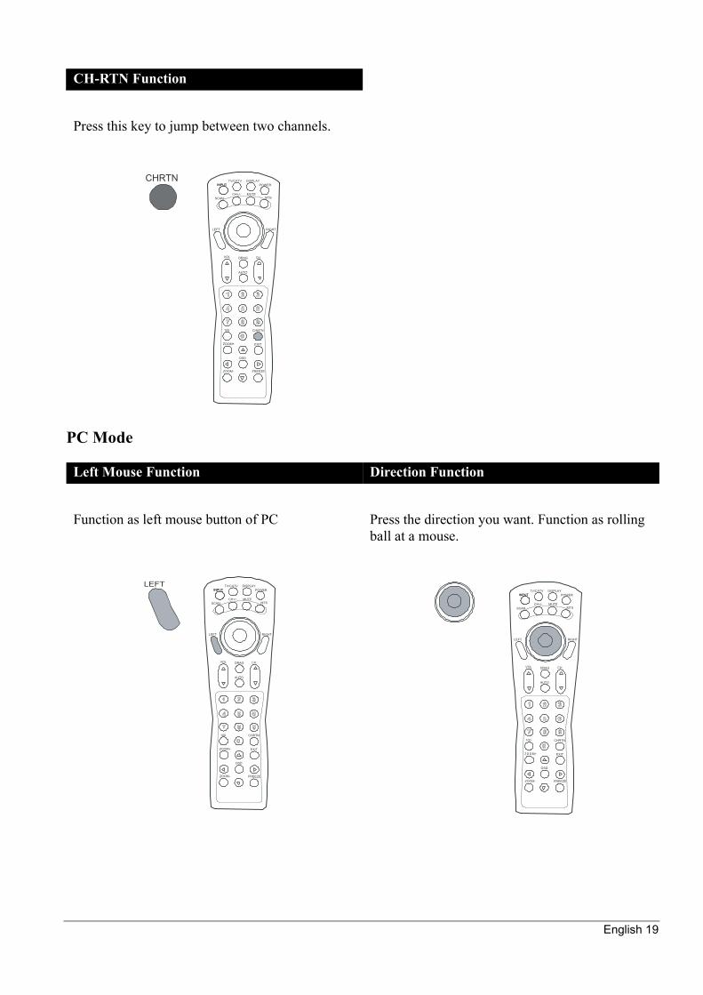
PC Mode
CH-RTN Function
Press this key to jump between two channels.
Left Mouse Function Direction Function
Function as left mouse button of PC Press the direction you want. Function as rolling ball at a mouse.
CHRTNINPUT POWER
SCANCH+/- MUTE
MTS
CHVOL DRAG
AUTO
CHRTN
EXIT
FREEZE
ZOOM+
ZOOM-
OSD
100
RIGHTLEFT
TV/CATV DISPLAYINPUT
LEFTINPUT POWER
SCANCH+/- MUTE
MTS
CHVOL DRAG
AUTO
CHRTN
EXIT
FREEZE
ZOOM+
ZOOM-
OSD
100
RIGHTLEFT
TV/CATV DISPLAYINPUT
INPUT POWER
SCANCH+/- MUTE
MTS
CHVOL DRAG
AUTO
CHRTN
EXIT
FREEZE
ZOOM+
ZOOM-
OSD
100
RIGHTLEFT
TV/CATV DISPLAYINPUT

English 20
Adjusting Function Mode
Right Mouse Function Mouse Drag Function
Function as right mouse button of PC This key simulates the mouse drag function as in PC system. Press this key to make mouse drag function (as if right mouse button is pressed continuously). Press again to back to normal situation.
Adjusting The Volume Adjusting The Channel
Volume : Use these two hot keys to adjust volume straight.
Press Volume to increase the volume
Press Volume to decrease the volume
Channel : Use these two hot keys to select channel straight (reserved) in TV mode.
Press Channel to increase the channel
Press Channel to decrease the channel
RIGHTINPUT POWER
SCANCH+/- MUTE
MTS
CHVOL DRAG
AUTO
CHRTN
EXIT
FREEZE
ZOOM+
ZOOM-
OSD
100
RIGHTLEFT
TV/CATV DISPLAYINPUT
DRAG INPUT POWER
SCANCH+/- MUTE
MTS
CHVOL DRAG
AUTO
CHRTN
EXIT
FREEZE
ZOOM+
ZOOM-
OSD
100
RIGHTLEFT
TV/CATV DISPLAYINPUT
VOLINPUT POWER
SCANCH+/- MUTE
MTS
CHVOL DRAG
AUTO
CHRTN
EXIT
FREEZE
ZOOM+
ZOOM-
OSD
100
RIGHTLEFT
TV/CATV DISPLAYINPUT CH INPUT POWER
SCANCH+/- MUTE
MTS
CHVOL DRAG
AUTO
CHRTN
EXIT
FREEZE
ZOOM+
ZOOM-
OSD
100
RIGHTLEFT
TV/CATV DISPLAYINPUT
English 21
OSD Function Mode
OSD Function:
PC:
TV:
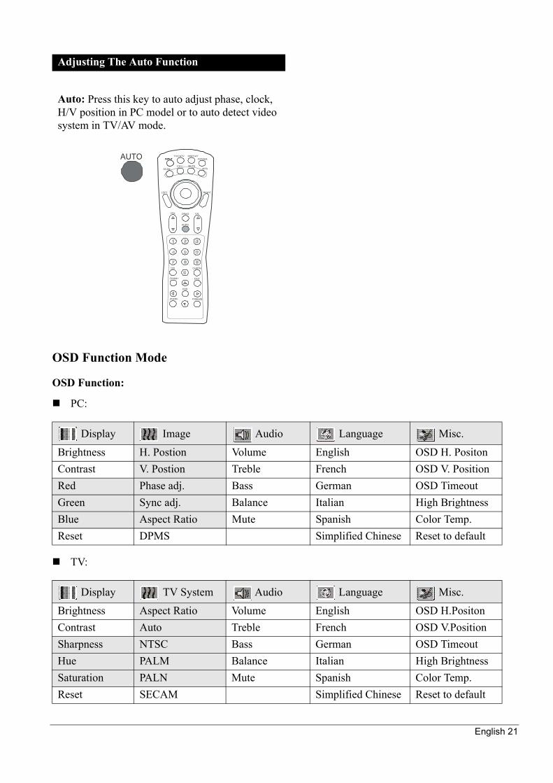
Adjusting The Auto Function
Auto: Press this key to auto adjust phase, clock, H/V position in PC model or to auto detect video system in TV/AV mode.
Display Image Audio Language Misc.
Brightness H. Postion Volume English OSD H. PositonContrast V. Postion Treble French OSD V. PositionRed Phase adj. Bass German OSD TimeoutGreen Sync adj. Balance Italian High BrightnessBlue Aspect Ratio Mute Spanish Color Temp.Reset DPMS Simplified Chinese Reset to default
Display TV System Audio Language Misc.
Brightness Aspect Ratio Volume English OSD H.PositonContrast Auto Treble French OSD V.PositionSharpness NTSC Bass German OSD TimeoutHue PALM Balance Italian High BrightnessSaturation PALN Mute Spanish Color Temp.Reset SECAM Simplified Chinese Reset to default
INPUT POWER
SCANCH+/- MUTE
MTS
CHVOL DRAG
AUTO
CHRTN
EXIT
FREEZE
ZOOM+
ZOOM-
OSD
100
RIGHTLEFT
TV/CATV DISPLAYINPUTAUTO
English 22
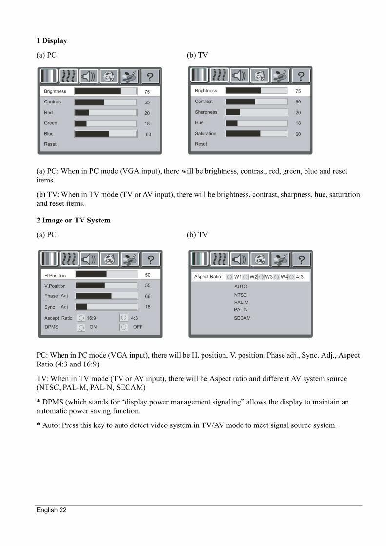
1 Display
(a) PC (b) TV
(a) PC: When in PC mode (VGA input), there will be brightness, contrast, red, green, blue and reset items.
(b) TV: When in TV mode (TV or AV input), there will be brightness, contrast, sharpness, hue, saturation and reset items.
2 Image or TV System
(a) PC (b) TV
PC: When in PC mode (VGA input), there will be H. position, V. position, Phase adj., Sync. Adj., Aspect Ratio (4:3 and 16:9)
TV: When in TV mode (TV or AV input), there will be Aspect ratio and different AV system source (NTSC, PAL-M, PAL-N, SECAM)
* DPMS (which stands for “display power management signaling” allows the display to maintain an automatic power saving function.
* Auto: Press this key to auto detect video system in TV/AV mode to meet signal source system.
BC
Brightness
Contrast
Red
Green
Blue
Reset
75
55
20
18
60
BC
Brightness
Contrast
Sharpness
Hue
Saturation
Reset
75
60
20
18
60
BC
H:Position
V.Position
Ascept Ratio 16:9 4:3
DPMS ON OFF
50
55
66
18
Phase
Sync
Adj
Adj
BC
AUTO
NTSC
PAL-M
PAL-N
SECAM
Aspect Ratio
English 23
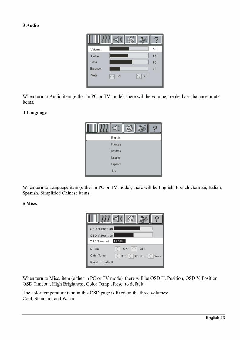
3 Audio
When turn to Audio item (either in PC or TV mode), there will be volume, treble, bass, balance, mute items.
4 Language
When turn to Language item (either in PC or TV mode), there will be English, French German, Italian, Spanish, Simplified Chinese items.
5 Misc.
When turn to Misc. item (either in PC or TV mode), there will be OSD H. Position, OSD V. Position, OSD Timeout, High Brightness, Color Temp., Reset to default.
The color temperature item in this OSD page is fixed on the three volumes:Cool, Standard, and Warm
BC
Volume
Treble
ON OFF
50
55
66
20
Bass
Mute
Balance
ABC
OSD H.Position
OSD V. Position
OSD Timeout
DPMS ON OFF
Color Temp
Reset to default
Cool Standard Warm
19 sec.
English 24
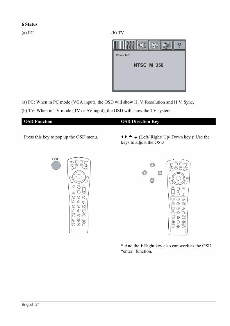
6 Status
(a) PC (b) TV
(a) PC: When in PC mode (VGA input), the OSD will show H. V. Resolution and H.V. Sync.
(b) TV: When in TV mode (TV or AV input), the OSD will show the TV system.
OSD Function OSD Direction Key
Press this key to pop up the OSD menu. (Left/ Right/ Up/ Down key.): Use the keys to adjust the OSD
* And the Right key also can work as the OSD “enter” function.
BC
NTSC M 358
Video Info
OSDINPUT POWER
SCANCH+/- MUTE
MTS
CHVOL DRAG
AUTO
CHRTN
EXIT
FREEZE
ZOOM+
ZOOM-
OSD
100
RIGHTLEFT
TV/CATV DISPLAYINPUT
INPUT POWER
SCANCH+/- MUTE
MTS
CHVOL DRAG
AUTO
CHRTN
EXIT
FREEZE
ZOOM+
ZOOM-
OSD
100
RIGHTLEFT
TV/CATV DISPLAYINPUT

English 25
Screen Function Mode
OSD Exit Key
Press this key to exit OSD menu directly.
Zoom + Function Zoom – Function
Press this key to enlarge the screen Press this key to minify the screen
EXIT INPUT POWER
SCANCH+/- MUTE
MTS
CHVOL DRAG
AUTO
CHRTN
EXIT
FREEZE
ZOOM+
ZOOM-
OSD
100
RIGHTLEFT
TV/CATV DISPLAYINPUT
INPUT POWER
SCANCH+/- MUTE
MTS
CHVOL DRAG
AUTO
CHRTN
EXIT
FREEZE
ZOOM+
ZOOM-
OSD
100
RIGHTLEFT
TV/CATV DISPLAYINPUT
ZOOM+ZOOM-
INPUT POWER
SCANCH+/- MUTE
MTS
CHVOL DRAG
AUTO
CHRTN
EXIT
FREEZE
ZOOM+
ZOOM-
OSD
100
RIGHTLEFT
TV/CATV DISPLAYINPUT
English 26
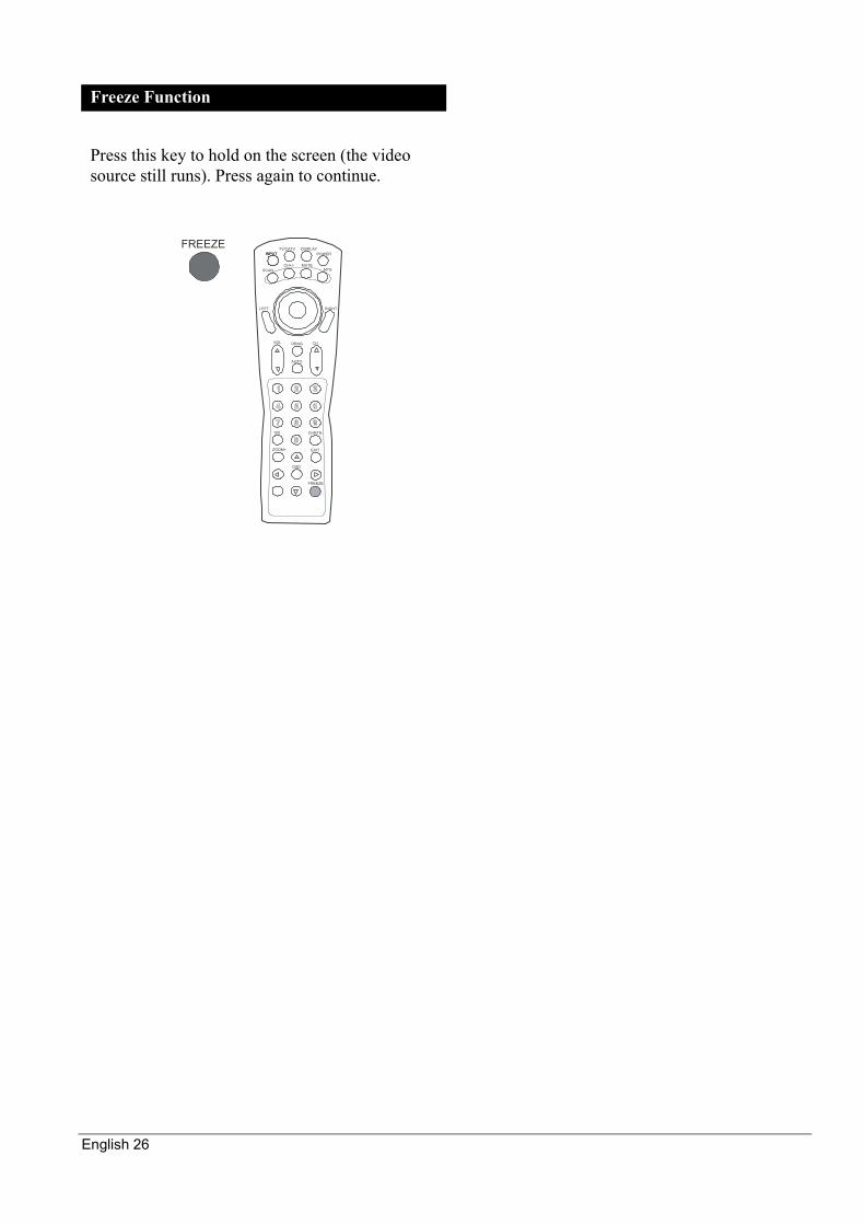
Freeze Function
Press this key to hold on the screen (the video source still runs). Press again to continue.
FREEZEINPUT POWER
SCANCH+/- MUTE
MTS
CHVOL DRAG
AUTO
CHRTN
EXIT
FREEZE
ZOOM+
ZOOM-
OSD
100
RIGHTLEFT
TV/CATV DISPLAYINPUT
English 27
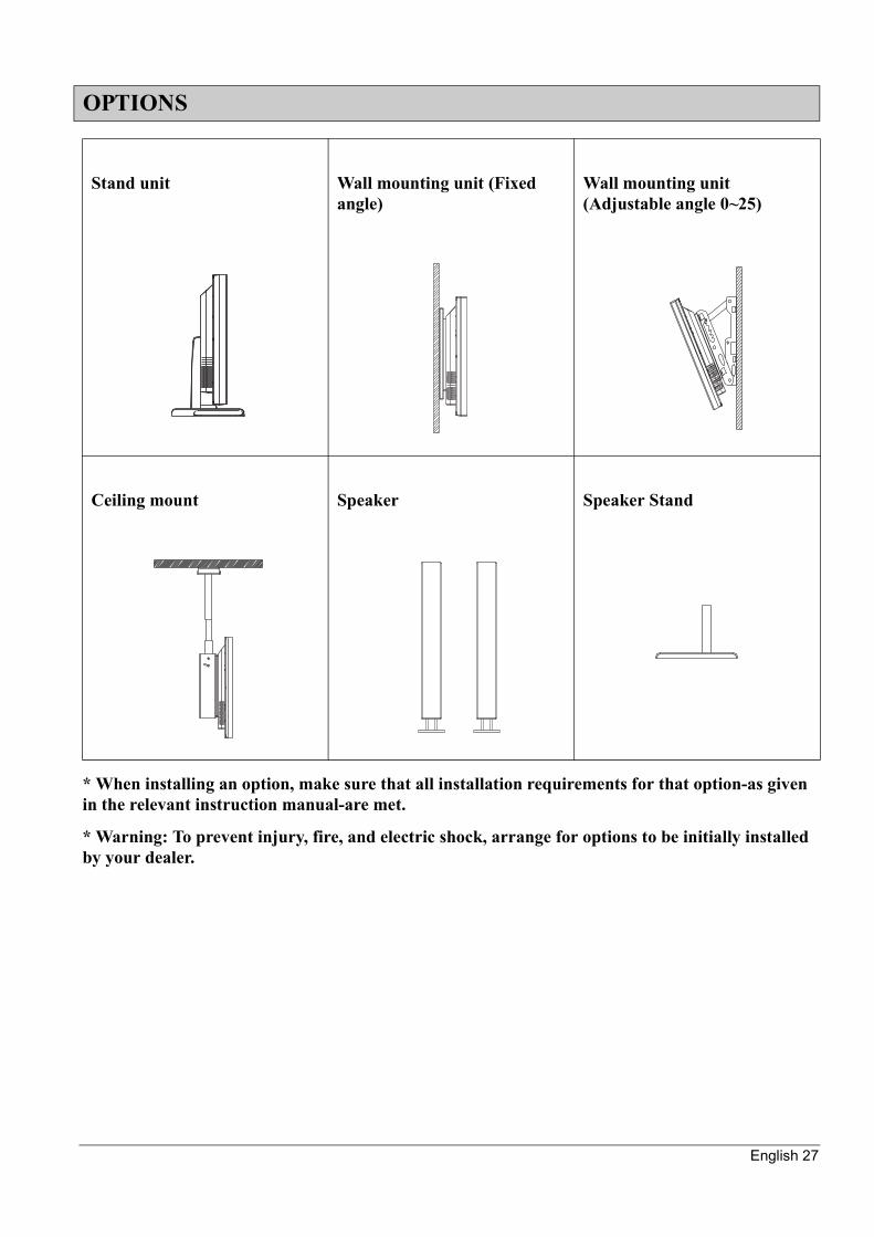
* When installing an option, make sure that all installation requirements for that option-as given in the relevant instruction manual-are met.
* Warning: To prevent injury, fire, and electric shock, arrange for options to be initially installed by your dealer.
OPTIONS
Stand unit Wall mounting unit (Fixed angle)
Wall mounting unit (Adjustable angle 0~25)
Ceiling mount Speaker Speaker Stand
English 28
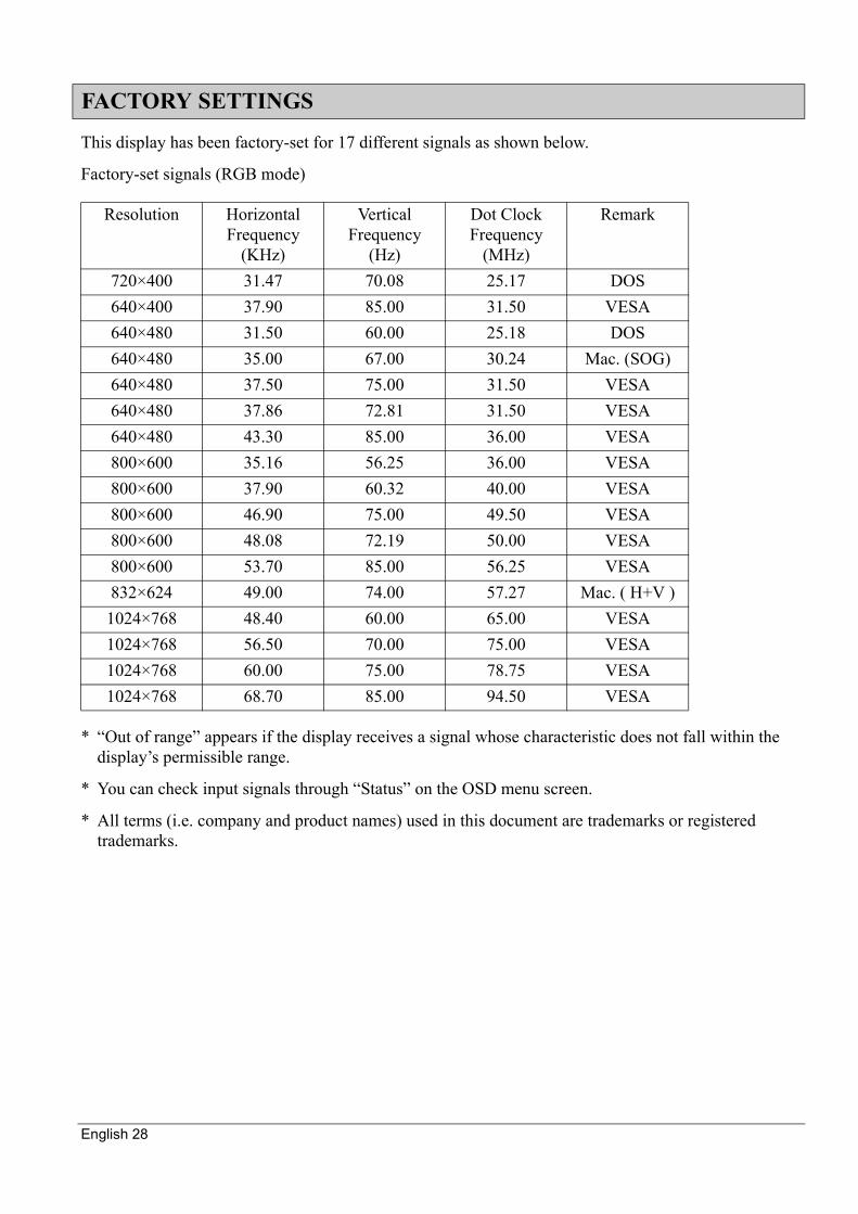
This display has been factory-set for 17 different signals as shown below.
Factory-set signals (RGB mode)
* “Out of range” appears if the display receives a signal whose characteristic does not fall within the display’s permissible range.
* You can check input signals through “Status” on the OSD menu screen.
* All terms (i.e. company and product names) used in this document are trademarks or registered trademarks.
FACTORY SETTINGS
Resolution Horizontal Frequency
(KHz)
Vertical Frequency
(Hz)
Dot Clock Frequency
(MHz)
Remark
720×400 31.47 70.08 25.17 DOS640×400 37.90 85.00 31.50 VESA640×480 31.50 60.00 25.18 DOS640×480 35.00 67.00 30.24 Mac. (SOG)640×480 37.50 75.00 31.50 VESA640×480 37.86 72.81 31.50 VESA640×480 43.30 85.00 36.00 VESA800×600 35.16 56.25 36.00 VESA800×600 37.90 60.32 40.00 VESA800×600 46.90 75.00 49.50 VESA800×600 48.08 72.19 50.00 VESA800×600 53.70 85.00 56.25 VESA832×624 49.00 74.00 57.27 Mac. ( H+V )1024×768 48.40 60.00 65.00 VESA1024×768 56.50 70.00 75.00 VESA1024×768 60.00 75.00 78.75 VESA1024×768 68.70 85.00 94.50 VESA
English 29
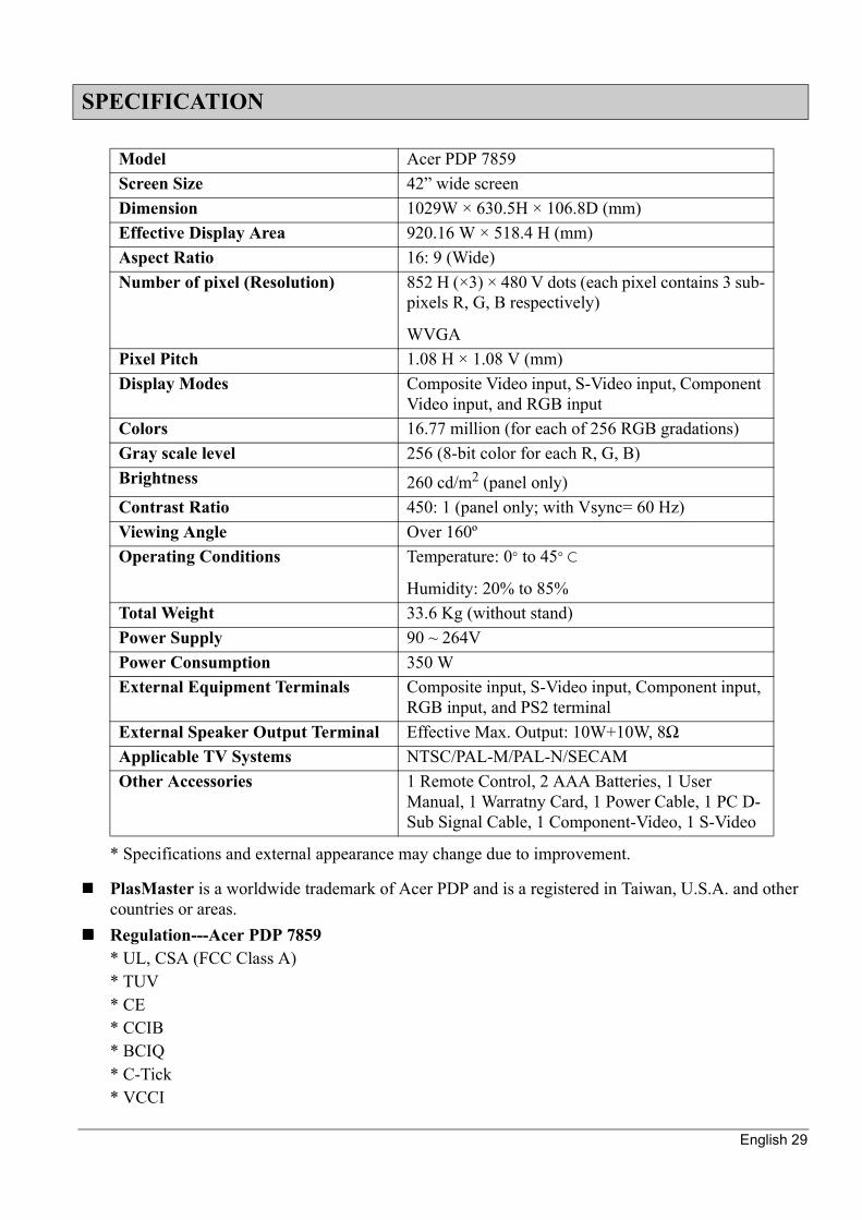
* Specifications and external appearance may change due to improvement.
PlasMaster is a worldwide trademark of Acer PDP and is a registered in Taiwan, U.S.A. and other countries or areas.Regulation---Acer PDP 7859* UL, CSA (FCC Class A)* TUV* CE* CCIB* BCIQ* C-Tick* VCCI
SPECIFICATION
Model Acer PDP 7859Screen Size 42” wide screenDimension 1029W × 630.5H × 106.8D (mm)Effective Display Area 920.16 W × 518.4 H (mm)Aspect Ratio 16: 9 (Wide)Number of pixel (Resolution) 852 H (×3) × 480 V dots (each pixel contains 3 sub-
pixels R, G, B respectively)
WVGAPixel Pitch 1.08 H × 1.08 V (mm)Display Modes Composite Video input, S-Video input, Component
Video input, and RGB inputColors 16.77 million (for each of 256 RGB gradations)Gray scale level 256 (8-bit color for each R, G, B)Brightness 260 cd/m2 (panel only)Contrast Ratio 450: 1 (panel only; with Vsync= 60 Hz)Viewing Angle Over 160ºOperating Conditions Temperature: 0° to 45° C
Humidity: 20% to 85%Total Weight 33.6 Kg (without stand)Power Supply 90 ~ 264VPower Consumption 350 WExternal Equipment Terminals Composite input, S-Video input, Component input,
RGB input, and PS2 terminalExternal Speaker Output Terminal Effective Max. Output: 10W+10W, 8ΩApplicable TV Systems NTSC/PAL-M/PAL-N/SECAMOther Accessories 1 Remote Control, 2 AAA Batteries, 1 User
Manual, 1 Warratny Card, 1 Power Cable, 1 PC D-Sub Signal Cable, 1 Component-Video, 1 S-Video

English 30
PrecautionBe sure to remove the power plug from the receptacle before cleaning the display.And be sure not to clean the display using a cloth dampened with volatile solvents, such as benzene or thinner. Such solvents can harm the display’s cabinet, the filter at the screen front, and the remote control. They can also cause paint to come off these sections.
Cleaning the cabinet and remote controlUse a soft cloth for cleaning.If the cabinet or remote control is heavily stained, soak a soft cloth in a mixture of water and detergent and squeeze it dry before wiping off the stains. Use a soft, dry cloth for final cleaning.
Cleaning the screenClean the screen gently with a soft cloth.The screen surface is fragile. Never attempt to clean it with a hard material. Press on it forcefully, or tap it.Check the following explanation again before asking for services. If the trouble cannot be recovered, consult your dealer.
CLEANING AND TROUBLESHOOTING
Problem ActionPower cannot be turned on *Check whether the power plug is securely inserted into the
receptacle.No images are displayed *Check the cable for disconnection
*Check whether the power for all input equipment is ON*Check for connection to wrong terminal or for wrong input mode
Remote control does not function properly
*Check for incorrect battery orientation*Check for dead batteries*Check for distance from the display*Check whether you are pointing the remote control transmitter properly at the display’s receiver*Check for any obstacle between the remote control and the display(See P 14 “Using the Remote Control”)
There are spots on the screen *Check whether your AV equipment is affected by interference from automobiles, trains, high-voltage transmission lines, neon signs or other potential sources of interference
Degrade colors/image quality *Check whether all image adjustments have been properly made(See P 22 “1 Display” and “2 Image or TV System”)
Improper screen position/size *Check whether screen position and size have been properly adjusted
No sound from external speakers
*Check cables for disconnection*Check whether you have set the display for use of external speakers
English 31
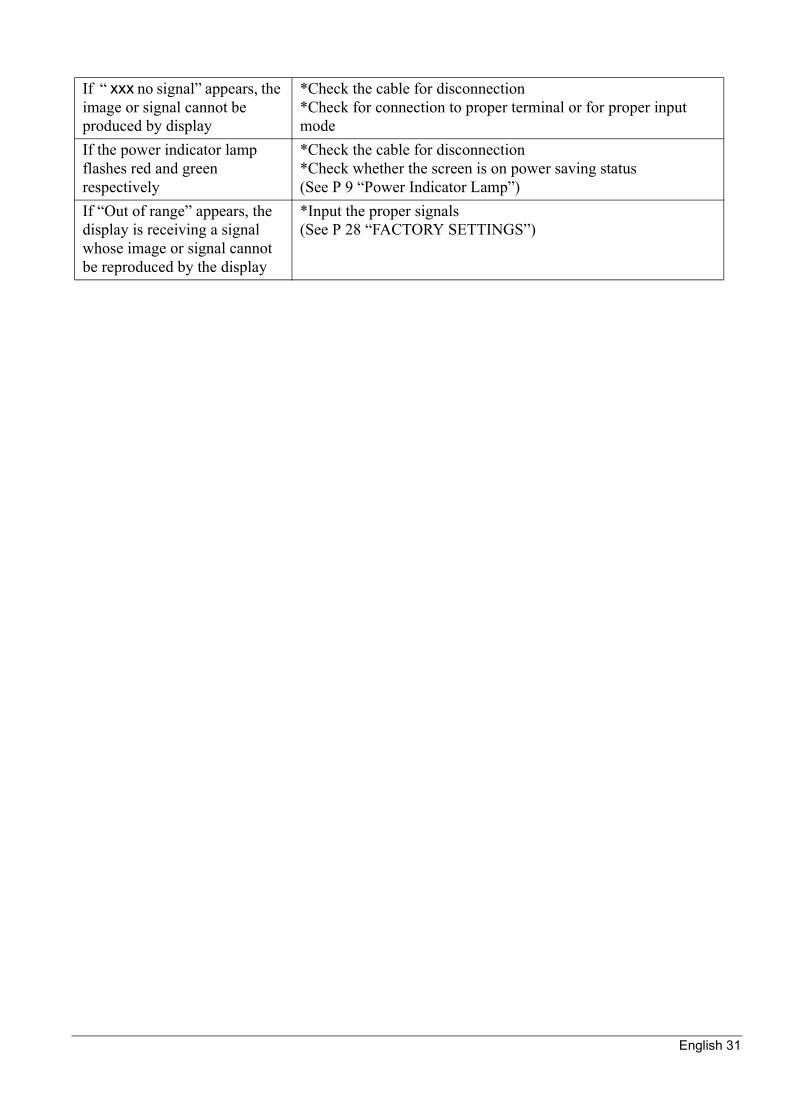
If “ xxx no signal” appears, the image or signal cannot be produced by display
*Check the cable for disconnection*Check for connection to proper terminal or for proper input mode
If the power indicator lamp flashes red and green respectively
*Check the cable for disconnection*Check whether the screen is on power saving status(See P 9 “Power Indicator Lamp”)
If “Out of range” appears, the display is receiving a signal whose image or signal cannot be reproduced by the display
*Input the proper signals(See P 28 “FACTORY SETTINGS”)
Related Documents