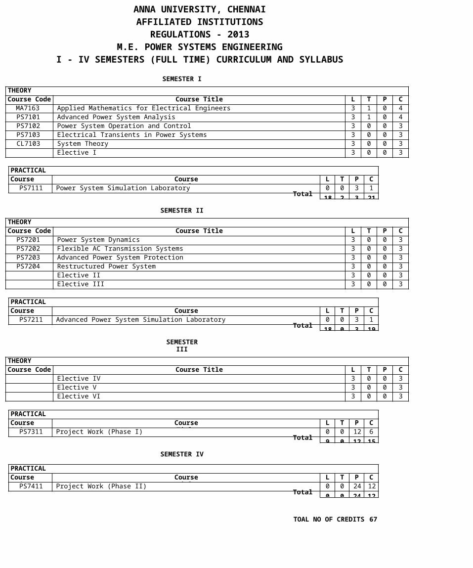
PRACTICAL Course Code Course Title L T P C PS7111 Power System Simulation Laboratory 0 0 3 1 18 2 3 21 PRACTICAL Course Code Course Title L T P C PS7211 Advanced Power System Simulation Laboratory 0 0 3 1 18 0 3 19 PRACTICAL Course Code Course Title L T P C PS7311 Project Work (Phase I) 0 0 12 6 9 0 12 15 PRACTICAL Course Code Course Title L T P C PS7411 Project Work (Phase II) 0 0 24 12 0 0 24 12 ANNA UNIVERSITY, CHENNAI AFFILIATED INSTITUTIONS REGULATIONS - 2013 M.E. POWER SYSTEMS ENGINEERING I - IV SEMESTERS (FULL TIME) CURRICULUM AND SYLLABUS SEMESTER I THEORY Course Code Course Title L T P C MA7163 Applied Mathematics for Electrical Engineers 3 1 0 4 PS7101 Advanced Power System Analysis 3 1 0 4 PS7102 Power System Operation and Control 3 0 0 3 PS7103 Electrical Transients in Power Systems 3 0 0 3 CL7103 System Theory 3 0 0 3 Elective I 3 0 0 3 Total SEMESTER II THEORY Course Code Course Title L T P C PS7201 Power System Dynamics 3 0 0 3 PS7202 Flexible AC Transmission Systems 3 0 0 3 PS7203 Advanced Power System Protection 3 0 0 3 PS7204 Restructured Power System 3 0 0 3 Elective II 3 0 0 3 Elective III 3 0 0 3 Total SEMESTER III THEORY Course Code Course Title L T P C Elective IV 3 0 0 3 Elective V 3 0 0 3 Elective VI 3 0 0 3 Total SEMESTER IV Total TOAL NO OF CREDITS 67

Welcome message from author
This document is posted to help you gain knowledge. Please leave a comment to let me know what you think about it! Share it to your friends and learn new things together.
Transcript
PRACTICALCourse Code
CourseTitle
L T P CPS7111 Power System Simulation Laboratory 0 0 3 1
18 2 3 21
PRACTICALCourse Code
CourseTitle
L T P CPS7211 Advanced Power System Simulation Laboratory 0 0 3 1
18 0 3 19
PRACTICALCourse Code
CourseTitle
L T P CPS7311 Project Work (Phase I) 0 0 12 6
9 0 12 15
PRACTICALCourse Code
CourseTitle
L T P CPS7411 Project Work (Phase II) 0 0 24 12
0 0 24 12
ANNA UNIVERSITY, CHENNAIAFFILIATED INSTITUTIONS
REGULATIONS - 2013M.E. POWER SYSTEMS ENGINEERING
I - IV SEMESTERS (FULL TIME) CURRICULUM AND SYLLABUS
SEMESTER ITHEORYCourse Code Course Title L T P C
MA7163 Applied Mathematics for Electrical Engineers 3 1 0 4PS7101 Advanced Power System Analysis 3 1 0 4PS7102 Power System Operation and Control 3 0 0 3PS7103 Electrical Transients in Power Systems 3 0 0 3CL7103 System Theory 3 0 0 3
Elective I 3 0 0 3
Total
SEMESTER IITHEORYCourse Code Course Title L T P C
PS7201 Power System Dynamics 3 0 0 3PS7202 Flexible AC Transmission Systems 3 0 0 3PS7203 Advanced Power System Protection 3 0 0 3PS7204 Restructured Power System 3 0 0 3
Elective II 3 0 0 3Elective III 3 0 0 3
Total
SEMESTERIII
THEORYCourse Code Course Title L T P C
Elective IV 3 0 0 3Elective V 3 0 0 3Elective VI 3 0 0 3
Total
SEMESTER IV
Total
TOAL NO OF CREDITS 67
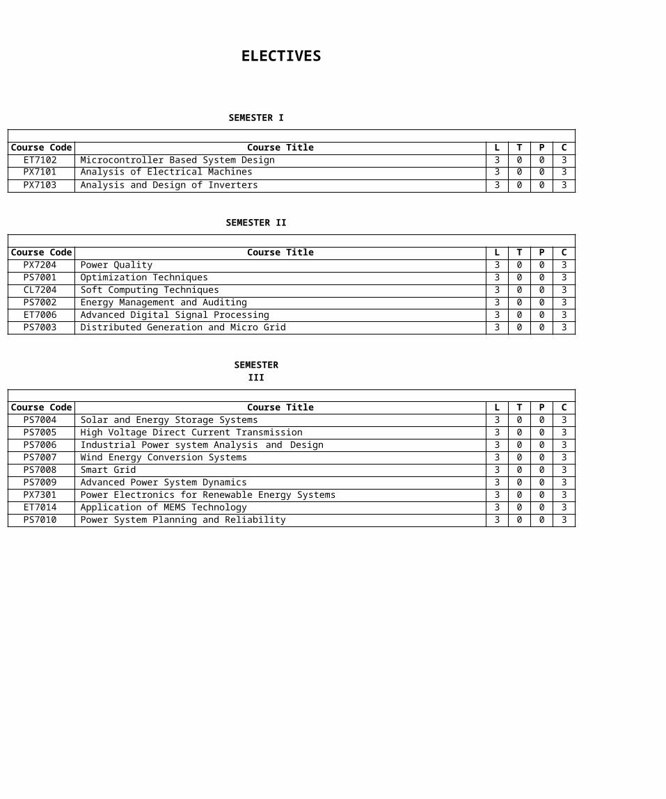
ELECTIVES
SEMESTER I
Course Code Course Title L T P CET7102 Microcontroller Based System Design 3 0 0 3PX7101 Analysis of Electrical Machines 3 0 0 3PX7103 Analysis and Design of Inverters 3 0 0 3
SEMESTER II
Course Code Course Title L T P CPX7204 Power Quality 3 0 0 3PS7001 Optimization Techniques 3 0 0 3CL7204 Soft Computing Techniques 3 0 0 3PS7002 Energy Management and Auditing 3 0 0 3ET7006 Advanced Digital Signal Processing 3 0 0 3PS7003 Distributed Generation and Micro Grid 3 0 0 3
SEMESTERIII
Course Code Course Title L T P CPS7004 Solar and Energy Storage Systems 3 0 0 3PS7005 High Voltage Direct Current Transmission 3 0 0 3PS7006 Industrial Power system Analysis and Design 3 0 0 3PS7007 Wind Energy Conversion Systems 3 0 0 3PS7008 Smart Grid 3 0 0 3PS7009 Advanced Power System Dynamics 3 0 0 3PX7301 Power Electronics for Renewable Energy Systems 3 0 0 3ET7014 Application of MEMS Technology 3 0 0 3PS7010 Power System Planning and Reliability 3 0 0 3
1
MA7163 APPLIED MATHEMATICS FOR ELECTRICAL ENGINEERSL T P C
3 1 0 4
OBJECTIVES: To develop the ability to apply the concepts of Matrix theory
and Linear programming in Electrical Engineering problems. To achieve an understanding of the basic concepts of one
dimensional random variables and apply in electrical engineering problems.
To familiarize the students in calculus of variations and solve problems using Fourier transforms associated with engineering applications.
UNIT I MATRIX THEORY(9+3) The Cholesky decomposition - Generalized Eigen vectors,Canonical basis - QR factorization - Least squares method -Singular value decomposition.
UNIT II CALCULUS OF VARIATIONS (9+3) Concept of variation and its properties – Euler’s equation – Functional dependant on first and higher order derivatives – Functionals dependant on functions of several independent variables – Variational problems with moving boundaries – problems with constraints - Direct methods: Ritz and Kantorovich methods.
UNIT III ONE DIMENSIONAL RANDOM VARIABLES(9+3) Random variables - Probability function – moments – momentgenerating functions and their properties – Binomial, Poisson,Geometric, Uniform, Exponential, Gamma and Normal distributions– Function of a Random Variable.
UNIT IV LINEAR PROGRAMMING(9+3) Formulation – Graphical solution – Simplexmethod – Two phase method - Transportation andAssignment Models
UNIT V FOURIER SERIES(9+3) Fourier Trigonometric series: Periodic function aspower signals – Convergence of series – Even and oddfunction: cosine and sine series – Non-periodic function:Extension to other intervals - Power signals: Exponential Fourierseries – Parseval’s theorem and power spectrum – Eigen value
2
problems and orthogonal functions – Regular Sturm-Liouvillesystems – Generalized Fourier series.
L:45 +T: 15 TOTAL: 60 PERIODSREFERENCES:
1. Richard Bronson, “Matrix Operation”, Schaum’s outline series, 2nd Edition, McGraw
Hill, 2011.2. Gupta, A.S., Calculus of Variations with Applications,
Prentice Hall of India Pvt. Ltd., New Delhi, 1997.3. Oliver C. Ibe, “Fundamentals of Applied Probability and Random Processes,
Academic Press, (An imprint of Elsevier), 2010.4. Taha, H.A., “Operations Research, An introduction”,
10th edition, Pearson education, New Delhi, 2010.5. Andrews L.C. and Phillips R.L., Mathematical Techniques forEngineers and
Scientists, Prentice Hall of India Pvt.Ltd., New Delhi, 2005.
3
6. Elsgolts, L., Differential Equations and the Calculus of Variations, MIR Publishers, Moscow, 1973.
7. Grewal, B.S., Higher Engineering Mathematics, 42ndedition, Khanna Publishers,
2012.
8. O'Neil, P.V., Advanced Engineering Mathematics, Thomson Asia Pvt. Ltd., Singapore, 2003.
9. Johnson R. A. and Gupta C. B., “Miller & Freund’s Probability and Statistics for Engineers”, Pearson Education, Asia, 7th Edition, 2007.
PS7101 ADVANCED POWER SYSTEM ANALYSISL T P C
3 1 0 4
OBJECTIVES To Introduce different techniques of dealing with sparse
matrix for large scale power systems. To impart in-depth knowledge on different methodsof power flow solutions. To perform optimal power flowsolutions in detail. To perform short circuit fault analysis and understand the
consequence of different type of faults. To Illustrate different numeric al integration methods
and factors influencing transient stability
UNIT I SOLUTION TECHNIQUE9Sparse Matrix techniques for large scale power systems: Optimalordering schemes for preserving sparsity. Flexible packedstorage scheme for storing matrix as compact arrays –Factorization by Bifactorization and Gauss eliminationmethods; Repeat solution using Left and Right factors and L andU matrices.UNIT II POWER FLOW ANALYSIS9
4
Power flow equation in real and polar forms; Review of Newton’smethod for solution; Adjustment of P-V buses; Review of FastDecoupled Power Flow method; Sensitivity factors for P-V busadjustment.UNIT III OPTIMAL POWER FLOW9Problem statement; Solution of Optimal Power Flow (OPF) – Thegradient method, Newton’s method, Linear Sensitivity Analysis; LPmethods – With real power variables only – LP method with ACpower flow variables and detailed cost functions; Securityconstrained Optimal Power Flow; Interior point algorithm; BusIncremental costs.UNIT IV SHORT CIRCUIT ANALYSIS9Formation of bus impedance matrix with mutual coupling (singlephase basis and three phase basis) - Computer method forfault analysis using ZBUS and sequence components.Derivation of equations for bus voltages, fault current andline currents, both in sequence and phase – symmetrical andunsymmetrical faults.
5
UNIT V TRANSIENT STABILITY ANALYSIS9Introduction, Numerical Integration Methods: Euler and FourthOrder Runge-Kutta methods, Algorithm for simulation of SMIB andmulti-machine system with classical synchronous machine model ;Factors influencing transient stability, Numerical stability andimplicit Integration methods.
REFERENCES:L:45 +T: 15 TOTAL: 60 PERIODS
1. A.J.Wood and B.F.Wollenberg,“Power Generation Operation and Control”, John Wiley and sons, New York, 1996.
2. W.F.Tinney and W.S.Meyer, “Solution of Large Sparse System by Ordered
Triangular Factorization” IEEE Trans. on Automatic Control, Vol : AC-18, pp:333-346, Aug 1973.
3. K.Zollenkopf, “Bi-Factorization: Basic Computational Algorithm and Programming
Techniques ; pp:75-96 ; Book on “Large Sparse Set of LinearSystems” Editor: J.K.Rerd,Academic Press, 1971.
4. M.A.Pai,” Computer Techniques in Power System Analysis”,Tata McGraw-Hill
Publishing Company Limited, New Delhi, 20065. G W Stagg , A.H El. Abiad “Computer Methods in Power
System Analysis”, McGraw Hill, 1968.6. P.Kundur, “Power System Stability and Control”, McGraw Hill, 1994.
PS7102 POWER SYSTEM OPERATION AND CONTROL L T P C
3 0 0 3COURSE OBJECTIVES To understand the fundamentals of speed governing system
and the concept of control areas. To provide knowledge about Hydrothermal scheduling, Unit
commitment and solution techniques. To understand the role of energy control center, SCADAand EMS functions.
6
UNIT I INTRODUCTION9System load variation: System load characteristics, load curves -daily, weekly and annual, load-duration curve, load factor,diversity factor. Reserve requirements: Installed reserves,spinning reserves, cold reserves, hot reserves. Overview ofsystem operation: Load forecasting, techniques of forecasting,basics of power system operation and control.UNIT II REAL POWER - FREQUENCY CONTROL 9Fundamentals of speed governing mechanism
and modelling:
Speed-loadcharacteristics – Load sharing between two synchronous machines
in parallel; conceptof control area, LFC control of a single-area system: Static and dynamic analysis of uncontrolled and controlled cases, Economic Dispatch Control. Multi-area systems: Two-
7
area system modelling; static analysis, uncontrolled case; tieline with frequency bias control of two-area system derivation,state variable model.UNIT III HYDROTHERMAL SCHEDULING PROBLEM9Hydrothermal scheduling problem: short term and long term-mathematical model, algorithm. Dynamic programming solutionmethodology for Hydro-thermal scheduling with pumped hydroplant: Optimization with pumped hydro plant-Scheduling of systemswith pumped hydro plant during off-peak seasons: algorithm.Selection of initial feasible trajectory for pumped hydro plant-Pumped hydro plant as spinning reserve unit- generation ofoutage induced constraint-Pumped hydro plant as Loadmanagement plant.UNIT IV UNIT COMMITMENT AND ECONOMIC DISPATCH9Statement of Unit Commitment (UC) problem; constraints in UC:spinning reserve, thermal unit constraints, hydro constraints,fuel constraints and other constraints; UC solution methods:Priority-list methods, forward dynamic programming approach,numerical problems .Incremental cost curve, co-ordinationequations without loss and with loss, solution by direct methodand λ-iteration method. Base point and participation factors.-Economic dispatch controller added to LFC control.UNIT V COMPUTER CONTROL OF POWER SYSTEMS9Energy control centre: Functions – Monitoring, data acquisitionand control. System hardware configuration – SCADA and EMSfunctions: Network topology determination, state estimation,security analysis and control. Various operating states: Normal,alert, emergency, in-extremis and restorative-State transitiondiagram showing various state transitions and control strategies.
REFERENCES:TOTAL : 45 PERIODS
1. Olle. I. Elgerd, ‘Electric Energy Systems Theory – An Introduction’, Tata McGraw Hill
Publishing Company Ltd, New Delhi, Second Edition, 2003.2. D.P. Kothari and I.J. Nagrath, ‘Modern Power System Analysis’, Third Edition, Tata
McGraw Hill Publishing Company Limited, New Delhi, 2003.3. L.L. Grigsby, ‘The Electric Power Engineering, Hand Book’,CRC Press & IEEE
8
Press, 20014. Allen.J.Wood and Bruce F.Wollenberg, ‘Power Generation,
Operation and Control’, John Wiley & Sons, Inc., 2003.5. P. Kundur, ‘Power System Stability & Control’, McGraw Hill Publications, USA, 1994
9
PS7103 ELECTRICAL TRANSIENTS IN POWER SYSTEMSL T P C3 0 0 3
OBJECTIVE: To gain knowledge in the sources and effects of lightning,
switching and temporary over voltages. Ability to model and estimate the overvoltages in power system To coordinate the insulation of power systemand protective devices. Ability to model and analyze power system and
equipment for transient over voltages using Electromagnetic Transient Program (EMTP).
UNIT I LIGHTNING OVERVOLTAGES9Mechanism and parameters of lightning flash, protective shadow,striking distance, electrogeometric model for lightning strike,Grounding for protection against lightning – Steady-state anddynamic tower-footing resistance, substation grounding Grid,Direct lightning strokes to overhead lines, without and withshield Wires.
UNIT II SWITCHING AND TEMPORARY OVERVOLTAGES9Switching transients – concept – phenomenon – system performanceunder switching surges, Temporary over voltages – load rejection– line faults – Ferro resonance, VFTO.
UNIT III TRAVELLING WAVES ON TRANSMISSION LINE9Circuits and distributed constants, wave equation, reflection andrefraction – behavior of travelling waves at the lineterminations – Lattice Diagrams – attenuation and distortion –multi-conductor system and multi velocity waves.
UNIT IV INSULATION CO-ORDINATION9Classification of over voltages and insulations forinsulation co-ordination– Characteristics of protectivedevices, applications, location of arresters – insulation co-ordination in AIS and GIS.
1
UNIT V COMPUTATION OF POWER SYSTEM TRANSIENTS9Modeling of power apparatus for transient studies – principles ofdigital computation – transmission lines, cables, transformer androtating machines – Electromagnetic Transient program – casestudies: line with short and open end, line terminated with R,L, C, transformer, and typical power system case study:simulation of possible over voltages in a high voltagesubstation.
TOTAL : 45
PERIODS REFERENCES1. Pritindra Chowdhari, “Electromagnetic transients in PowerSystem”, John Wiley and
Sons Inc., Second Edition, 2009.2. Allan Greenwood, “Electrical Transients in Power System”,Wiley & Sons Inc. New
York, 2012.3. Klaus Ragaller, “Surges in High Voltage Networks”, PlenumPress, New York, 1980.4. Rakosh Das Begamudre, “Extra High Voltage AC
Transmission Engineering”, (Second edition) Newage International (P) Ltd., New Delhi, 2006.
5. Naidu M S and Kamaraju V, “High VoltageEngineering”, Tata McGraw-Hill
Publishing Company Ltd., New Delhi, 2004.
1
6. IEEE Guide for safety in AC substation grounding IEEE Standard 80-2000.7. Working Group 33/13-09 (1988), ‘Very fast transient phenomena associated with
Gas Insulated System’, CIGRE, 33-13, pp. 1-20.
CL7103 SYSTEM THEORY LT P C
3 0 0 3OBJECTIVES
To educate on modeling and representing systems in state variable form To educate on solving linear and non-linear state equations To illustrate the role of controllability and observability To educate on stability analysis of systems usig Lyapunov’s theory To educate on modal concepts and design of state and
output feedback controllers and estimators
UNIT I STATE VARIABLE REPRESENTATION9Introduction-Concept of State-State equation for DynamicSystems -Time invariance and linearity- Non uniqueness of statemodel-State Diagrams - Physical System and State Assignment.
UNIT II SOLUTION OF STATE EQUATIONS9Existence and uniqueness of solutions to Continuous-time stateequations-Solution of Nonlinear and Linear Time Varying Stateequations-Evaluation of matrix exponential- System modes- Role ofEigenvalues and Eigenvectors.
UNIT III CONTROLLABILITY AND OBSERVABILITY9Controllability and Observability-Stabilizability andDetectability-Test for Continuous time Systems- Time varying andTime invariant case-Output Controllability-Reducibility- SystemRealizations.
1
UNIT IV STABILTY9Introduction-Equilibrium Points-Stability in the sense ofLyapunov-BIBO Stability-Stability of LTI Systems-EquilibriumStability of Nonlinear Continuous Time Autonomous Systems-The Direct Method of Lyapunov and the Linear Continuous-TimeAutonomous Systems-Finding Lyapunov Functions for NonlinearContinuous Time Autonomous Systems-Krasovskii and Variable-Gradiant Method.
UNIT V MODAL CONTROL9Introduction-Controllable and Observable Companion Forms-SISOand MIMO Systems- The Effect of State Feedback onControllability and Observability-Pole Placement by StateFeedback for both SISO and MIMO Systems-Full Order andReduced Order Observers.
TOTAL : 45 PERIODS
REFERENCES:1. M. Gopal, “Modern Control System Theory”, New Age International, 2005.2. K. Ogatta, “Modern Control Engineering”, PHI, 2002.
1
3. John S. Bay, “Fundamentals of Linear State Space Systems”, McGraw-Hill, 1999.4. D. Roy Choudhury, “Modern Control Systems”, New Age International, 2005.5. John J. D’Azzo, C. H. Houpis and S. N. Sheldon, “Linear Control System Analysis
and Design with MATLAB”, TaylorFrancis, 2003.
6. Z. Bubnicki, ”Modern Control Theory”, Springer, 2005.
PS7111 POWER SYSTEM SIMULATION LABORATORY L T P C
0 0 3 1OBJECTIVES
To have hands on experience on various system studies and different techniques used for system planning. Software packages.
To perform the dynamic analysis ofpower system
LIST OF EXPERIMENTS1. Power flow analysis by Newton-Raphson method and Fast decoupled method2. Transient stability analysis of single machine-infinite
bus system using classical machine model3. Contingency analysis: Generator shift factors and line outagedistribution factors4. Economic dispatch using lambda-iteration method5. Unit commitment: Priority-list schemes and dynamic programming6. Analysis of switching surge using EMTP: Energisation
of a long distributed- parameter line7. Analysis of switching surge using EMTP : Computation of transient recovery voltage8. Familiarization of Relay Test Kit
1
9. Simulation and Implementation of Voltage Source Inverter10. Digital Over Current Relay Setting and Relay Coordination.11. Co-ordination of over-current and distance relays for radial line protection
TOTAL : 45 PERIODS
1
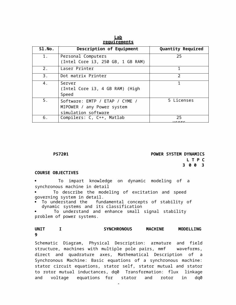
La br e quir e me nts
Sl.No. Description of Equipment Quantity Required1. Personal Computers
(Intel Core i3, 250 GB, 1 GB RAM)25
2. Laser Printer 13. Dot matrix Printer 24. Server
(Intel Core i3, 4 GB RAM) (High SpeedProcessor)
1
5. Software: EMTP / ETAP / CYME / MIPOWER / any Power system simulation software
5 Licenses
6. Compilers: C, C++, Matlab 25users
PS7201 POWER SYSTEM DYNAMICSL T P C
3 0 0 3COURSE OBJECTIVES To impart knowledge on dynamic modeling of asynchronous machine in detail To describe the modeling of excitation and speedgoverning system in detail. To understand the fundamental concepts of stability of
dynamic systems and its classification To understand and enhance small signal stabilityproblem of power systems.
UNIT I SYNCHRONOUS MACHINE MODELLING9Schematic Diagram, Physical Description: armature and fieldstructure, machines with multiple pole pairs, mmf waveforms,direct and quadrature axes, Mathematical Description of aSynchronous Machine: Basic equations of a synchronous machine:stator circuit equations, stator self, stator mutual and statorto rotor mutual inductances, dq0 Transformation: flux linkageand voltage equations for stator and rotor in dq0
1
coordinates, electrical power and torque, physical interpretationof dq0 transformation, Per Unit Representations: Lad-reciprocalper unit system and that from power-invariant form of Park’stransformation; Equivalent Circuits for direct andquadrature axes, Steady-state Analysis: Voltage, current andflux-linkage relationships, Phasor representation, Rotor angle,Steady-state equivalent circuit, Computation of steady-statevalues, Equations of Motion: Swing Equation, calculation ofinertia constant, Representation in system studies, SynchronousMachine Representation in Stability Studies: Simplificationsfor large-scale studies : Neglect of stator p terms andspeed
1
variations, Simplified model with amortisseurs neglected: two-axis model with amortisseur windings neglected, classical model.
UNIT II MODELLING OF EXCITATION AND SPEED GOVERNING SYSTEMS9Excitation System Requirements; Elements of an Excitation System;Types of Excitation System; Control and protective functions;IEEE (1992) block diagram for simulation of excitation systems.Turbine and Governing System Modeling: Functional Block Diagramof Power Generation and Control, Schematic of a hydroelectricplant, classical transfer function of a hydraulic turbine (noderivation), special characteristic of hydraulic turbine,electrical analogue of hydraulic turbine, Governor for HydraulicTurbine: Requirement for a transient droop, Block diagram ofgovernor with transient droop compensation, Steam turbinemodeling: Single reheat tandem compounded type only and IEEEblock diagram for dynamic simulation; generic speed-governingsystem model for normal speed/load control function.
UNIT III SMALL-SIGNAL STABILITY ANALYSIS WITHOUT CONTROLLERS9Classification of Stability, Basic Concepts and Definitions:Rotor angle stability, The Stability Phenomena. FundamentalConcepts of Stability of Dynamic Systems: State- spacerepresentation, stability of dynamic system, Linearization, Eigenproperties of the state matrix: Eigen values and eigenvectors,modal matrices, Eigen value and stability, mode shape andparticipation factor. Single-Machine Infinite Bus (SMIB)Configuration: Classical Machine Model stability analysiswith numerical example, Effects of Field Circuit Dynamics:synchronous machine, network and linearised system equations,block diagram representation with K-constants; expression for K-constants (no derivation), effect of field flux variation onsystem stability: analysis with numerical example.UNIT IV SMALL-SIGNAL STABILITY ANALYSIS WITH CONTROLLERS9Effects Of Excitation System: Equations with definitions ofappropriate K-constants and simple thyristor excitation systemand AVR, block diagram with the excitation system, analysis ofeffect of AVR on synchronizing and damping components using anumerical example, Power System Stabilizer: Block diagram with
1
AVR and PSS, Illustration of principle of PSS application withnumerical example, Block diagram of PSS with description, systemstate matrix including PSS, analysis of stability with numericala example. Multi-Machine Configuration: Equations in a commonreference frame, equations in individual machine rotorcoordinates, illustration of formation of system state matrixfor a two-machine system with classical models for synchronousmachines, illustration of stability analysis using a numericalexample. Principle behind small-signal stability improvementmethods: delta-omega and delta P-omega stabilizers.UNIT V ENHANCEMENT OF SMALL SIGNAL STABILITY9Power System Stabilizer – Stabilizer based on shaft speed signal(delta omega) – Delta–P-Omega stabilizer-Frequency-based stabilizers – DigitalStabilizer – Excitation control design – Exciter gain – Phaselead compensation – Stabilizing signal washout stabilizer gain –Stabilizer limits
TOTAL : 45 PERIODS
1
REFERENCES:1. P. W. Sauer and M. A. Pai,” Power System Dynamics and Stability”, Stipes
Publishing Co, 20072. IEEE Committee Report, "Dynamic Models for Steam and Hydro Turbines in Power
System Studies”, IEEE Trans., Vol.PAS-92, pp 1904-1915, November/December,1973. on Turbine-Governor Model.
3. P.M Anderson and A.A Fouad, “Power System Control and Stability”, Iowa State
University Press, Ames, Iowa, 1978.4. R.Ramunujam,” Power System Dynamics Analysis and Simulation, PHI Learning
Private Limited, New Delhi, 20095.. P. Kundur, “Power System Stability and Control”, McGraw-Hill, 1993.
PS7202 FLEXIBLE AC TRANSMISSION SYSTEMS L T P C
3 0 0 3OBJECTIVES
To emphasis the need for FACTS controllers. To learn the characteristics, applications and modeling of series and shunt
FACTS controllers. To analyze the interaction of different FACTS
controller and perform control coordination
UNIT I INTRODUCTION9Review of basics of power transmission networks-control of powerflow in AC transmission line- Analysis of uncompensated ACTransmission line- Passive reactive power compensation: Effectof series and shunt compensation at the mid-point of the line
2
on power transfer- Need for FACTS controllers- types of FACTScontrollers.UNIT II STATIC VAR COMPENSATOR (SVC)9Configuration of SVC- voltage regulation by SVC- Modelling of SVCfor load flow analysis- Modelling of SVC for stability studies-Design of SVC to regulate the mid-point voltage of a SMIBsystem- Applications: transient stability enhancement andpower oscillation damping of SMIB system with SVC connected atthe mid-point of the line.UNIT III THYRISTOR AND GTO THYRISTOR CONTROLLED SERIES
CAPACITORS (TCSC and GCSC) 9
Concepts of Controlled Series Compensation – Operationof TCSC and GCSC- Analysis of TCSC-GCSC – Modelling ofTCSC and GCSC for load flow studies- modeling TCSC and GCSCfor stability studied- Applications of TCSC and GCSC.
2
UNIT IV VOLTAGE SOURCE CONVERTER BASED FACTS CONTROLLERS9Static synchronous compensator(STATCOM)- Static synchronousseries compensator(SSSC)- Operation of STATCOM and SSSC-Powerflow control with STATCOM and SSSC- Modelling of STATCOM and SSSCfor power flow and transient stability studies –operation ofUnified and Interline power flow controllers(UPFC and IPFC)-Modelling of UPFC and IPFC for load flow and transient stabilitystudies- Applications.UNIT V CONTROLLERS AND THEIR COORDINATION9FACTS Controller interactions – SVC–SVC interaction - co-ordination of multiple controllers using linear controltechniques – Quantitative treatment of controlcoordination.
REFERENCES:TOTAL : 45 PERIODS
1. A.T.John, “Flexible AC Transmission System”, Institution of Electrical and Electronic
Engineers (IEEE), 1999.2. Narain G.Hingorani, Laszio. Gyugyl, “Understanding FACTS Concepts and
Technology of Flexible AC Transmission System”, Standard Publishers, Delhi 2001.
3. V. K.Sood, “HVDC and FACTS controllers- Applications of Static Converters in
Power System”, 2004, Kluwer Academic Publishers.4. Mohan Mathur, R., Rajiv. K. Varma, “Thyristor – Based Facts Controllers for
Electrical Transmission Systems”, IEEE press and John Wiley & Sons, Inc.
5. K.R.Padiyar,” FACTS Controllers in Power Transmission and Distribution”, New
Age International(P) Ltd., Publishers New Delhi, Reprint 2008,
2
PS7203 ADVANCED POWER SYSTEM PROTECTION L T P C
3 0 0 3OBJECTIVES
To illustrate concepts of transformer protection To describe about the various schemes of Over current protection To analyse distance and carrier protection To familiarize the concepts of Busbar protection and Numerical protection
UNIT I OVER CURRENT PROTECTION9Zones of protection – Primary and Backup protection – operatingprinciples and Relay Construction - Time – Currentcharacteristics-Current setting – Time setting-Over currentprotective schemes - Reverse power or directional relay -Protection of parallel feeders - Protection of ring feeders- Earth fault and phase fault protection -
2
Combined Earth fault and phase fault protection scheme -Phase fault protective scheme directional earth fault relay -Static over current relays; numerical example for a radial feederUNIT II EQUIPMENT PROTECTION9Types of transformers – Phasor diagram for a three – Phasetransformer-Equivalent circuit of transformer – Types offaults in transformers- Over – current protection PercentageDifferential Protection of Transformers - Inrushphenomenon-High resistance Ground Faults in Transformers - Inter-turn faults in transformers - Incipient faults in transformers- Phenomenon of over-fluxing in transformers - Transformerprotection application chart .Generator protection: Electricalcircuit of the generator – Various faults and abnormal operatingconditions-stator faults-rotor faults –Abnormal operatingconditions; numerical examples for typical transformerand generator protection schemesUNIT III DISTANCE AND CARRIER PROTECTION OF TRANSMISSION LINES9Drawback of over – Current protection – Introduction todistance relay – Simple impedance relay – Reactance relay– mho relays comparison of distance relay – Distanceprotection of a three – Phase line-reasons for inaccuracy ofdistance relay reach - Three stepped distance protection -Trip contact configuration for the three - Stepped distanceprotection - Three-stepped protection of three-phase lineagainst all ten shunt faults - Impedance seen from relayside - Three-stepped protection of double end fed lines-needfor carrier – Aided protection – Various options for acarrier–Coupling and trapping the carrier into the desired line section- Unit type carrier aided directional comparison relaying –Carrier aided distance schemes for acceleration of zone ΙΙ.;numerical example for a typical distance protection scheme for atransmission line.UNIT IV BUSBAR PROTECTION9Introduction – Differential protection of busbars-externaland internal fault - Actual behaviors of a protective CT -Circuit model of a saturated CT - External fault with one CTsaturation :need for high impedance – Minimum internal fault
2
that can be detected by the high – Stability ratio ofhigh impedance busbar differential scheme - Supervisoryrelay-protection of three – Phase busbars-Numerical exampleson design of high impedance busbar differential scheme.UNIT V NUMERICAL PROTECTION9Introduction–Block diagram of numerical relay - Sampling theorem-Correlation with a reference wave–Least error squared (LES)technique-Digital filtering-numerical over - Current protection–Numerical transformer differential protection-Numerical distanceprotection of transmission line
REFERENCESTOTAL : 45 PERIODS
1. P.Kundur, “Power System Stability and Control”, McGraw-Hill, 1993.2. Protective Relaying for Power System II Stanley Horowitz,IEEE press , New York,
20083. T.S.M. Rao, Digital Relay / Numerical relays , Tata McGraw Hill, New Delhi, 19894. Y.G. Paithankar and S.R Bhide, “Fundamentals of PowerSystem Protection”,
Prentice-Hall of India, 2003
2
5. Badri Ram and D.N. Vishwakarma, “Power System Protection and Switchgear”, Tata
McGraw- Hill Publishing Company, 2002.
PS7204 RESTRUCTURED POWER SYSTEMLT PC
3 0 0 3OBJECTIVES
To Introduce the restructuring of power industry and marketmodels. To impart knowledge on fundamental concepts of congestion management. To analyze the concepts of locational marginal pricing
and financial transmission rights. To Illustrate about various power sectors in India
UNIT I INTRODUCTION TO RESTRUCTURING OF POWER INDUSTRY9Introduction: Deregulation of power industry, Restructuringprocess, Issues involved in deregulation, Deregulation of variouspower systems – Fundamentals of Economics: Consumer behavior,Supplier behavior, Market equilibrium, Short and long run costs,Various costs of production – Market models: Market modelsbased on Contractual arrangements, Comparison of various marketmodels, Electricity vis – a – vis other commodities, Marketarchitecture, Case study.UNIT II TRANSMISSION CONGESTION MANAGEMENT9Introduction: Definition of Congestion, reasons fortransfer capability limitation, Importance of congestionmanagement, Features of congestion management – Classification ofcongestion management methods – Calculation of ATC - Non –market methods – Market methods – Nodal pricing – Inter zonal andIntra zonal congestion management – Price area congestionmanagement – Capacity alleviation method.UNIT III LOCATIONAL MARGINAL PRICES ANDFINANCIAL
2
TRANSMISSION RIGHTS 9
Mathematical preliminaries: - Locational marginal pricing–Lossless DCOPF model for LMP calculation – Loss compensatedDCOPF model for LMP calculation – ACOPF model for LMPcalculation – Financial Transmission rights – Risk hedgingfunctionality - Simultaneous feasibility test and revenueadequency – FTR issuance process: FTR auction, FTR allocation –Treatment of revenue shortfall – Secondary trading of FTRs – Flowgate rights – FTR and market power - FTR and merchanttransmission investment.UNIT IV ANCILLARY SERVICE MANAGEMENT AND PRICING OF
TRANSMISSION NETWORK 9
Introduction of ancillary services – Types of Ancillaryservices – Classification of Ancillary services – Loadgeneration balancing related services – Voltage control andreactive power support devices – Black start capability service- How to obtain ancillary service –Co-optimization of energy andreserve services - International comparison
2
Transmission pricing – Principles – Classification – Rolled intransmission pricing methods – Marginal transmission pricingparadigm – Composite pricing paradigm – Merits and demerits ofdifferent paradigm.
UNIT V REFORMS IN INDIAN POWER SECTOR9Introduction – Framework of Indian power sector – Reforminitiatives - Availability based tariff – Electricity act 2003 –Open access issues – Power exchange – Reforms in the near future
REFERENCESTOTAL : 45 PERIODS
1. Sally Hunt,” Making competition work in electricity”, , John Willey and Sons Inc.
20022. Steven Stoft,” Power system economics: designing markets for electricity”, John
Wiley & Sons, 2002.3. Mohammad Shahidehpour, Muwaffaq Alomoush, Marcel
Dekker, “Restructured electrical power systems: operation, trading and volatility” Pub., 2001
4. Kankar Bhattacharya, Jaap E. Daadler, Math H.J. Boolen,” Operation of restructured
power systems”, Kluwer Academic Pub., 2001.
PS7211 ADVANCED POWER SYSTEM SIMULATION LABORATORY LT P C
0 0 3 1OBJECTIVES
To analyze the effect of FACTS controllers by performing steady state analysis. To have hands on experience on different wind energy conversion technologies
LIST OF EXPERIMENTS1. Small-signal stability analysis of single machine-infinite
bus system using classical machine model
2
2. Small-signal stability analysis of multi-machine configuration with classical machine model
3. Induction motor starting analysis4. Load flow analysis of two-bus system with STATCOM5. Transient analysis of two-bus system with STATCOM6. Available Transfer Capability calculation using an existing load flow program7. Study of variable speed wind energy conversion system- DFIG8. Study of variable speed wind energy conversion system- PMSG
2
9. Computation of harmonic indices generated by a rectifier feeding a R-L load10. Design of active filter for mitigating harmonics.
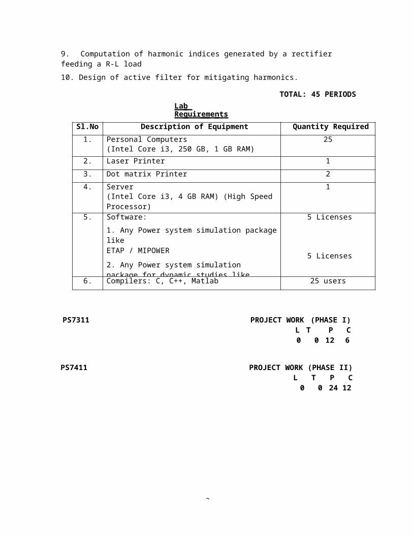
La b Re quir e me nts
TOTAL: 45 PERIODS
Sl.No.
Description of Equipment Quantity Required1. Personal Computers
(Intel Core i3, 250 GB, 1 GB RAM)25
2. Laser Printer 13. Dot matrix Printer 24. Server
(Intel Core i3, 4 GB RAM) (High SpeedProcessor)
1
5. Software:1. Any Power system simulation packagelikeETAP / MIPOWER2. Any Power system simulation package for dynamic studies like
5 Licenses
5 Licenses
6. Compilers: C, C++, Matlab 25 users
PS7311 PROJECT WORK (PHASE I)L T P C0 0 12 6
PS7411 PROJECT WORK (PHASE II)L T P C0 0 24 12
3
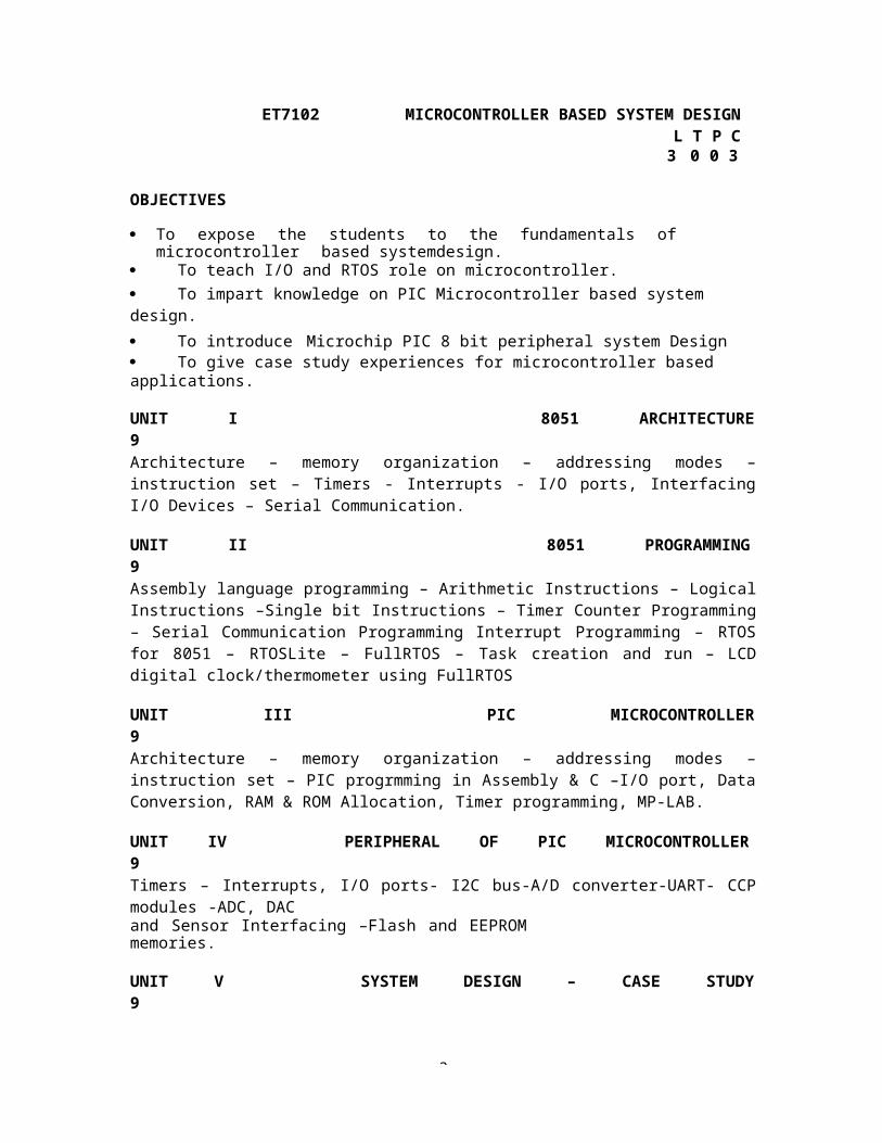
ET7102 MICROCONTROLLER BASED SYSTEM DESIGNL T P C3 0 0 3
OBJECTIVES
To expose the students to the fundamentals of microcontroller based systemdesign.
To teach I/O and RTOS role on microcontroller. To impart knowledge on PIC Microcontroller based system design. To introduce Microchip PIC 8 bit peripheral system Design To give case study experiences for microcontroller based applications.
UNIT I 8051 ARCHITECTURE9Architecture – memory organization – addressing modes –instruction set – Timers - Interrupts - I/O ports, InterfacingI/O Devices – Serial Communication.
UNIT II 8051 PROGRAMMING9Assembly language programming – Arithmetic Instructions – LogicalInstructions –Single bit Instructions – Timer Counter Programming– Serial Communication Programming Interrupt Programming – RTOSfor 8051 – RTOSLite – FullRTOS – Task creation and run – LCDdigital clock/thermometer using FullRTOS
UNIT III PIC MICROCONTROLLER9Architecture – memory organization – addressing modes –instruction set – PIC progrmming in Assembly & C –I/O port, DataConversion, RAM & ROM Allocation, Timer programming, MP-LAB.
UNIT IV PERIPHERAL OF PIC MICROCONTROLLER9Timers – Interrupts, I/O ports- I2C bus-A/D converter-UART- CCPmodules -ADC, DACand Sensor Interfacing –Flash and EEPROMmemories.
UNIT V SYSTEM DESIGN – CASE STUDY9
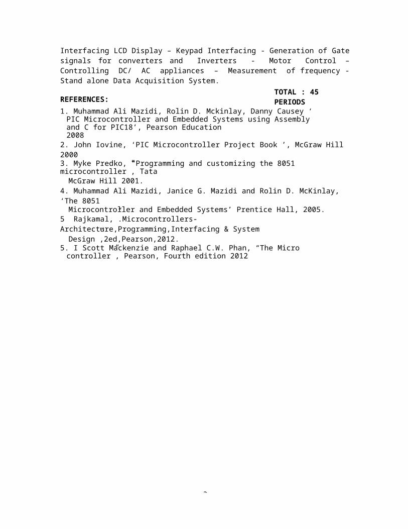
3
Interfacing LCD Display – Keypad Interfacing - Generation of Gatesignals for converters and Inverters - Motor Control –Controlling DC/ AC appliances – Measurement of frequency -Stand alone Data Acquisition System.
REFERENCES:TOTAL : 45 PERIODS
1. Muhammad Ali Mazidi, Rolin D. Mckinlay, Danny Causey ‘ PIC Microcontroller and Embedded Systems using Assembly and C for PIC18’, Pearson Education2008
2. John Iovine, ‘PIC Microcontroller Project Book ’, McGraw Hill 20003. Myke Predko, “Programming and customizing the 8051 microcontroller”, TataMcGraw Hill 2001.
4. Muhammad Ali Mazidi, Janice G. Mazidi and Rolin D. McKinlay, ‘The 8051Microcontroller and Embedded Systems’ Prentice Hall, 2005.
5 Rajkamal,”.Microcontrollers-Architecture,Programming,Interfacing & SystemDesign”,2ed,Pearson,2012.
5. I Scott Mackenzie and Raphael C.W. Phan, “The Micro controller”, Pearson, Fourth edition 2012
3
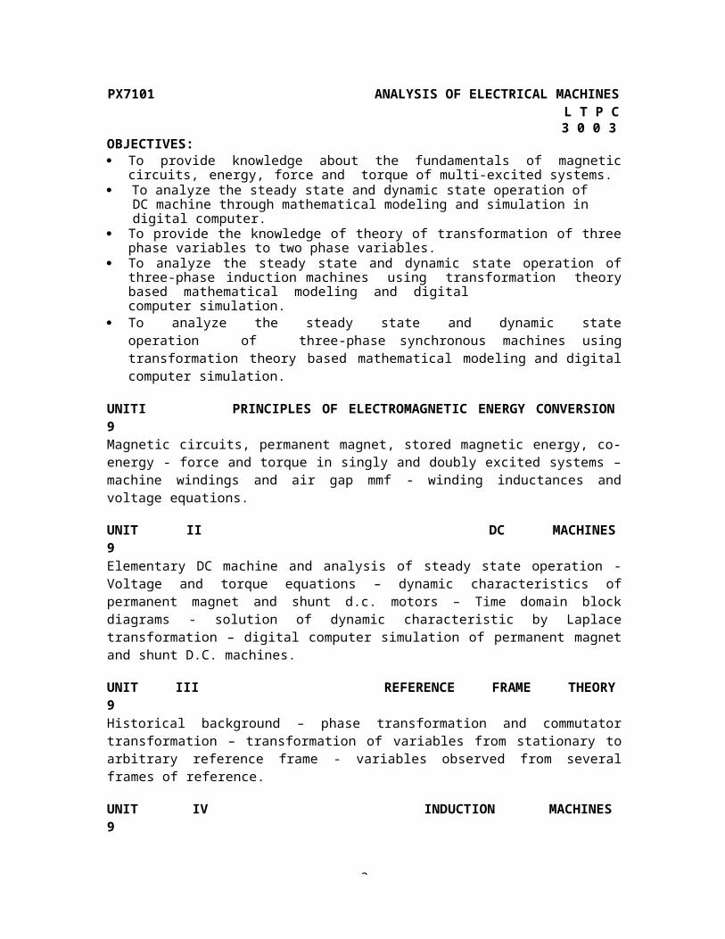
PX7101 ANALYSIS OF ELECTRICAL MACHINESL T P C3 0 0 3
OBJECTIVES: To provide knowledge about the fundamentals of magnetic
circuits, energy, force and torque of multi-excited systems. To analyze the steady state and dynamic state operation of
DC machine through mathematical modeling and simulation in digital computer.
To provide the knowledge of theory of transformation of threephase variables to two phase variables.
To analyze the steady state and dynamic state operation ofthree-phase induction machines using transformation theorybased mathematical modeling and digitalcomputer simulation.
To analyze the steady state and dynamic stateoperation of three-phase synchronous machines usingtransformation theory based mathematical modeling and digitalcomputer simulation.
UNITI PRINCIPLES OF ELECTROMAGNETIC ENERGY CONVERSION9Magnetic circuits, permanent magnet, stored magnetic energy, co-energy - force and torque in singly and doubly excited systems –machine windings and air gap mmf - winding inductances andvoltage equations.
UNIT II DC MACHINES9Elementary DC machine and analysis of steady state operation -Voltage and torque equations – dynamic characteristics ofpermanent magnet and shunt d.c. motors – Time domain blockdiagrams - solution of dynamic characteristic by Laplacetransformation – digital computer simulation of permanent magnetand shunt D.C. machines.
UNIT III REFERENCE FRAME THEORY9Historical background – phase transformation and commutatortransformation – transformation of variables from stationary toarbitrary reference frame - variables observed from severalframes of reference.
UNIT IV INDUCTION MACHINES9

3
Three phase induction machine, equivalent circuit and analysis ofsteady state operation– free acceleration characteristics – voltage and torqueequations in machine variablesand arbitrary reference frame variables – analysis of dynamicperformance for load torque variations – digital computersimulation.
UNIT V SYNCHRONOUS MACHINES9Three phase synchronous machine and analysis of steady stateoperation - voltage and torque equations in machine variables androtor reference frame variables (Park’s equations) – analysis ofdynamic performance for load torque variations – digital computersimulation.
TOTAL : 45 PERIODS
REFERENCES1. Paul C.Krause, Oleg Wasyzczuk, Scott S, Sudhoff, “Analysis of Electric
Machinery and Drive Systems”, John Wiley, SecondEdition, 2010.
3
2. P S Bimbhra, “Generalized Theory of Electrical Machines”, Khanna
Publishers, 2008.3. A.E, Fitzgerald, Charles Kingsley, Jr, and Stephan D, Umanx, “ Electric
Machinery”, Tata McGraw Hill, 5th Edition, 1992
PX7103 ANALYSIS AND DESIGN OF INVERTERS L T P C
3 0 0 3OBJECTIVES :
To Provide the electrical circuit concepts behind the different working modes of inverters so as to enable deep understanding of their operation.
To equip with required skills to derive the criteria for thedesign of power converters for UPS,Drives etc.,
Ability to analyse and comprehend the various operating modes of different configurations of power converters.
Ability to design different single phase andthree phase inverters.
UNIT I SINGLE PHASE INVERTERS12Introduction to self commutated switches : MOSFET and IGBT -Principle of operation of half and full bridge inverters –Performance parameters – Voltage control of single phaseinverters using various PWM techniques – various harmonicelimination techniques – forced commutated Thyristor inverters –Design of UPS
UNIT II THREE PHASE VOLTAGE SOURCE INVERTERS9180 degree and 120 degree conduction mode inverters with star anddelta connected loads – voltage control of three phase inverters:single, multi pulse, sinusoidal, space vector modulationtechniques – Application to drive system
3
UNIT III CURRENT SOURCE INVERTERS9Operation of six-step thyristor inverter – inverter operationmodes – load – commutated inverters – Auto sequential currentsource inverter (ASCI) – current pulsations – comparison ofcurrent source inverter and voltage source inverters – PWMtechniques for current source inverters.
UNIT IV MULTILEVEL & BOOST INVERTERS9Multilevel concept – diode clamped – flying capacitor – cascadetype multilevel inverters- Comparison of multilevel inverters - application ofmultilevel inverters – PWMtechniques for MLI – Single phase & Three phase Impedancesource inverters .
UNIT V RESONANT INVERTERS6Series and parallel resonant inverters - voltage control ofresonant inverters – Class Eresonant inverter – resonant DC –link inverters.
3
REFERENCESTOTAL : 45 PERIODS
1. Rashid M.H., “Power Electronics Circuits, Devices and Applications ", Prentice Hall
India, Third Edition, New Delhi, 2004.2. Jai P.Agrawal, “Power Electronics Systems”, Pearson Education, Second Edition,
2002.3. Bimal K.Bose “Modern Power Electronics and AC Drives”,
Pearson Education, Second Edition, 2003.4. Ned Mohan,T.M Undeland and W.P Robbin, “Power Electronics: converters,
Application and design” John Wiley and sons.Wiley India edition, 2006.
5. Philip T. krein, “Elements of Power Electronics” Oxford University Press -1998.6. P.C. Sen, “Modern Power Electronics”, Wheeler Publishing Co, First Edition, New
Delhi,1998.7. P.S.Bimbra, “Power Electronics”, Khanna Publishers, EleventhEdition, 2003.
PX7204 POWER QUALITY LT P C
3 0 0 3OBJECTIVES :
To understand the various powerquality issues. To understand the concept of power and power factor in
single phase and three phase systems supplying non linear loads
To understand the conventional compensation techniques used for power factor correction and load voltage regulation.
To understand the active compensation techniques used for power factor correction.
To understand the active compensation techniques used forload voltage regulation.
UNIT I INTRODUCTION9
3
Introduction – Characterisation of Electric Power Quality:Transients, short duration and long duration voltage variations,Voltage imbalance, waveform distortion, Voltage fluctuations,Power frequency variation, Power acceptability curves –power quality problems: poor load power factor, Non linear andunbalanced loads, DC offset in loads, Notching in load voltage,Disturbance in supply voltage – Power quality standards.
UNIT II ANALYSIS OF SINGLE PHASE AND THREE PHASE SYSTEM9Single phase linear and non linear loads – single phasesinusoidal, non sinusoidal source – supplying linear andnonlinear load – three phase Balance system – three phaseunbalanced system – three phase unbalanced and distorted sourcesupplying non linear loads – convept of pf – three phase threewire – three phase four wire system.
UNIT III CONVENTIONAL LOAD COMPENSATION METHODS9Principle of load compensation and voltage regulation –classical load balancing problem : open loop balancing –closed loop balancing, current balancing – harmonic
3
reduction and voltage sag reduction – analysis of unbalance – instantaneous of real and reactive powers – Extraction of fundamental sequence component from measured.
UNIT IV LOAD COMPENSATION USING DSTATCOM9Compensating single – phase loads – Ideal three phase shuntcompensator structure – generating reference currents usinginstantaneous PQ theory – Instantaneous symmetrical componentstheory – Generating reference currents when the souce isunbalanced – Realization and control of DSTATCOM – DSTATCOM inVoltage control mode
UNIT V SERIES COMPENSATION OF POWER DISTRIBUTION SYSTEM9Rectifier supported DVR – Dc Capacitor supported DVR – DVRStructure – voltageRestoration – Series Active Filter – Unified powerquality conditioner.
TOTAL : 45 PERIODS
REFERENCES1. Arindam Ghosh “Power Quality Enhancement Using Custom
Power Devices”, Kluwer Academic Publishers, 20022. G.T.Heydt, “Electric Power Quality”, Stars in a CirclePublications, 1994(2nd edition)3. Power Quality -R.C. Duggan4. Power System Harmonics –A.J. Arrillga5. Power Electronic Converter Harmonics –Derek A. Paice.
3
PS7001 OPTIMIZATION TECHNIQUESL T P C
3 0 0 3OBJECTIVES
To introduce the different optimization problems and techniques To study the fundamentals of the linear and non-linear
programming problem. To understand the concept of dynamic programming and
genetic algorithm techniqueUNIT I INTRODUCTION9Definition, Classification of optimization problems, ClassicalOptimization Techniques, Single and Multiple Optimization withand without inequality constraints.UNIT II LINEAR PROGRAMMING (LP)9Simplex method of solving LPP, revised simplex method, duality,Constrained optimization, Theorems and procedure, Linearprogramming, mathematical model, solution technique, duality.UNIT III NON LINEAR PROGRAMMING9Steepest descent method, conjugates gradient method, Newton’sMethod, Sequential quadratic programming, Penalty functionmethod, augmented Lagrange multiplier method.,UNIT IV DYNAMIC PROGRAMMING (DP)9Multistage decision processes, concept of sub-optimization andprinciple of optimality, Recursive relations, Integer Linearprogramming, Branch and bound algorithm
UNIT V GENETIC ALGORITHM9Introduction to genetic Algorithm, working principle, coding ofvariables, fitness function, GA operators; Similarities anddifferences between Gas and traditional methods; Unconstrainedand constrained optimization using genetic Algorithm, real codedgas, Advanced Gas, global optimization using GA, Applications topower system.
4
TOTAL : 45 PERIODSREFERENCES:1. Computational methods in Optimization, Polak , Academic Press,1971.2. Optimization Theory with applications, Pierre D.A., Wiley Publications,1969.3. Taha, H. A., Operations Research: An Introduction, Seventh Edition, Pearson
Education Edition, Asia, New Delhi ,2002.4. S.S. Rao,”Optimization – Theory and Applications”, Wiley-Eastern Limited, 1984.5. G.Luenberger,” Introduction of Linear and Non-Linear Programming” , Wesley
Publishing Company, 2011
4
CL7204 SOFT COMPUTING TECHNIQUESL T P C
3 0 0 3
OBJECTIVES
To expose the concepts of feed forwardneural networks. To provide adequate knowledge about feed backneural networks. To teach about the concept of fuzziness involvedin various systems. To expose the ideas aboutgenetic algorithm To provide adequate knowledge about of FLCand NN toolbox
UNIT I INTRODUCTION AND ARTIFICIAL NEURAL NETWORKS9Introduction of soft computing - soft computing vs. hardcomputing- various types of soft computing techniques-applications of soft computing-Neuron- Nerve structure andsynapse- Artificial Neuron and its model- activation functions-Neural network architecture- single layer and multilayer feedforward networks- McCullochPitts neuron model- perceptron model-Adaline and Madaline- multilayer perception model- backpropogation learning methods- effect of learning rule coefficient-back propagation algorithm- factors affecting back propagationtraining- applications.
UNIT II ARTIFICIAL NEURAL NETWORKS9Counter propagation network- architecture- functioning &characteristics of counter- Propagation network-Hopfield/Recurrent network- configuration- stability constraints-associative memory- and characteristics- limitations andapplications- Hopfield v/s Boltzman machine- Adaptive ResonanceTheory- Architecture- classifications- Implementation andtraining-Associative Memory.
UNIT III FUZZY LOGIC SYSTEM9Introduction to crisp sets and fuzzy sets- basic fuzzy setoperation and approximate reasoning. Introduction tofuzzy logic modeling and control- Fuzzification-
4
inferencingand defuzzification-Fuzzy knowledge and rule bases-Fuzzy modeling and control schemes for nonlinear systems. Selforganizing fuzzy logic control- Fuzzy logic control fornonlinear time delay system.
UNIT IV GENETIC ALGORITHM9Basic concept of Genetic algorithm and detail algorithmic steps-adjustment of free Parameters- Solution of typical controlproblems using genetic algorithm- Concept on some other searchtechniques like tabu search and ant colony search techniques forsolving optimization problems.
UNIT V APPLICATIONS9GA application to power system optimization problem- Case studies: Identification and control of linear and nonlinear dynamic systems using Matlab-Neural Network toolbox. Stability analysis of Neural Network interconnection systems- Implementation of fuzzy logic controller using Matlab fuzzy logic toolbox-Stability analysis of fuzzy control systems.
TOTAL : 45 PERIODS
4
REFERENCES1. Laurene V. Fausett, Fundamentals of Neural Networks: Architectures, Algorithms
And Applications, Pearson Education,2. Timothy J. Ross, “Fuzzy Logic with Engineering Applications” Wiley India.3. Zimmermann H.J. "Fuzzy set theoryand its Applications"
Springer international edition, 2011.4. David E.Goldberg, “Genetic Algorithms in Search, Optimization, and Machine
Learning”, Pearson Education, 2009.5. W.T.Miller, R.S.Sutton and P.J.Webrose, “Neural Networks for Control”, MIT Press,
1996.
PS7002 ENERGY MANAGEMENT AND AUDITING L T P C3 0
0 3OBJECTIVES
To study the concepts behind economic analysis and Load management. To emphasize the energy management on various
electrical equipments and metering. To illustrate the concept of lighting systems and cogeneration.
UNIT I INTRODUCTION9Need for energy management - energy basics- designing andstarting an energy management program – energy accounting -energymonitoring, targeting and reporting- energy audit process.UNIT II ENERGY COST AND LOAD MANAGEMENT9Important concepts in an economic analysis - Economic models-Timevalue of money- Utility rate structures- cost of electricity-Lossevaluation- Load management: Demand control techniques-Utilitymonitoring and control system-HVAC and energy management-Economic justification
4
UNIT III ENERGY MANAGEMENT FOR MOTORS, SYSTEMS, AND ELECTRICAL EQUIPMENT 9
Systems and equipment- Electric motors-Transformers and reactors-Capacitors and synchronous machinesUNIT IV METERING FOR ENERGY MANAGEMENT9Relationships between parameters-Units of measure-Typical costfactors- Utility meters - Timing of meter disc for kilowattmeasurement - Demand meters - Paralleling of current transformers- Instrument transformer burdens-Multitasking solid-state meters- Metering location vs. requirements- Metering techniques andpractical examples
4
UNIT V LIGHTING SYSTEMS & COGENERATION9Concept of lighting systems - The task and the working space -Light sources - Ballasts - Luminaries - Lighting controls-Optimizing lighting energy - Power factor and effect of harmonicson power quality - Cost analysis techniques-Lighting and energystandardsCogeneration: Forms of cogeneration - feasibility ofcogeneration- Electrical interconnection.
REFERENCESTOTAL : 45 PERIODS
1. Reay D.A, Industrial Energy Conservation, 1stedition, PergamonPress, 1977.2. IEEE Recommended Practice for Energy Management in Industrialand Commercial
Facilities, IEEE, 196.3. Amit K. Tyagi, Handbook on Energy Audits and Management, TERI, 2003.4. Barney L. Capehart, Wayne C. Turner, and William J. Kennedy, Guide to Energy
Management, Fifth Edition, The Fairmont Press, Inc., 20065. Eastop T.D & Croft D.R, Energy Efficiency for Engineers and Technologists,. Logman
Scientific & Technical, ISBN-0-582-03184, 1990.
ET7006 ADVANCED DIGITAL SIGNAL PROCESSING L T P C
3 0 0 3OBJECTIVES To expose the students to the fundamentals of digital
signal processing in frequency domain& its application To teach the fundamentals of digital signal
processing in time-frequency domain& its application To compare Architectures & features of Programmable DSprocessors To discuss on Application development with
commercial family of DS Processors To design & develop logical functions of
DSProcessors with Re- Programmable logics &Devices
4
UNIT I INTRODUCTION TO DIGITAL SIGNAL PROCESSING12Introduction, A Digital Signal-Processing System, The SamplingProcess, Discrete Time Sequences, Discrete Fourier Transform(DFT) and Fast Fourier Transform (FFT), Linear Time-InvariantSystems, Decimation and Interpolation, Digital Filters, FIRFilters, IIR Filters.
UNIT II WAVELET TRANSFORM6Introduction to continuous wavelet transform- discrete wavelettransform -orthogonal wavelet decomposition- MultiresolutionAnalysis-Wavelet function- DWT,bases,orthogonal Basis-Scalingfunction, Wavelet coefficients- ortho normal wavelets and theirrelationship to filter banks- Digital filtering interpolation (i)Decomposition filters, (ii) reconstruction, the signal- ExampleMRA- Haar & Daubechies wavelet.
4
UNIT III ARCHITECTURES OF COMMERCIAL DIGITAL SIGNAL PROCESSORS12Introduction, catogorisation of DSP Processors, Fixed Point(Blackfin),Floating Point (SHARC),TI TMS 320c6xxx & OMAPprocessors TMS320C54X & 54xx on Basic Architecture – comparison :of functional variations of Computational building blocks, MAC,Bus Architecture and memory, Data Addressing, Parallelismand pipelining, Parallel I/O interface,Memory Interface,Interrupt, DMA (one example Architecture in each of these casestudies).
UNIT IV INTERFACING I/O PERIPHERALS FOR DSP BASEDAPPLICATIONS 6Introduction, External Bus Interfacing Signals, MemoryInterface, Parallel I/O Interface, Programmed I/O, Interrupts andI / O Direct Memory Access (DMA).-Introduction, Design ofDecimation and Interpolation Filter, FFT Algorithm, PIDController ,Application for Serial Interfacing, DSP based PowerMeter, Position control , CODEC Interface .
UNIT V VLSI IMPLEMENTATION9Low power Design-need for Low power VLSI chips-Basics of DSPsystem architecture design using VHDL programming, Mapping of DSPalgorithm onto hardware, Realisation of MAC & Filter structure.
REFERENCES:TOTAL : 45 PERIODS
1. John G. Proaks, Dimitris G. Manolakis, “Digital Signal Processing”, Pearson
Education 2002.2. Avatar Sing, S. Srinivasan, “Digital Signal Processing- Implementation using
DSP Microprocessors with Examples from TMS320C54xx”, Thomson India,2004.
3. Lars Wanhammer, “DSP Integrated Circuits”, Academic press, 1999,NewYork.4. Lyla B Das,” Embedded Systems-An Integrated Approach”,Pearson20135. Ashok Ambardar,”Digital Signal Processing: A Modern Introduction”,Thomson
India edition, 2007.
4
6. Raghuveer M.Rao and Ajit S. Bapardikar, Wavelet transforms- Introduction to theory and applications, Pearson Education, 2000.
7. K.P. Soman and K.L. Ramchandran,Insight into WAVELETS from theory to
practice, Eastern Economy Edition, 20088. Ifeachor E. C., Jervis B. W ,”Digital Signal
Processing: A practical approach, Pearson-Education, PHI/ 2002
9. B Venkataramani and M Bhaskar “Digital Signal Processors”, TMH, 2nd, 201010. Peter Pirsch “Architectures for Digital Signal Processing”, John Weily, 200711. Vinay K.Ingle,John G.Proakis,”DSP-A Matlab BasedApproach”,Cengage
Learning,201012. Taan S.Elali,”Discrete Systems and Digital Signal
Processing with Matlab”,CRC Press2009.
4
PS7003 DISTRIBUTED GENERATION AND MICROGRIDL T P C
3 0 0 3
To illustrate the concept of distributed generation To analyze the impact of grid integration. To study concept of Microgrid and its configuration
UNIT I INTRODUCTION9Conventional power generation: advantages and disadvantages,Energy crises, Non- conventional energy (NCE) resources: reviewof Solar PV, Wind Energy systems, Fuel Cells, micro-turbines,biomass, and tidal sources.
UNIT II DISTRIBUTED GENERATIONS (DG)9Concept of distributed generations, topologies,selection of sources, regulatory standards/ framework,Standards for interconnecting Distributed resources to electricpower systems: IEEE 1547. DG installation classes, securityissues in DG implementations. Energy storage elements:Batteries, ultra-capacitors, flywheels. Captive power plants
UNIT III IMPACT OF GRID INTEGRATION9Requirements for grid interconnection, limits on operationalparameters,: voltage, frequency, THD, response to gridabnormal operating conditions, islanding issues. Impact ofgrid integration with NCE sources on existing power system:reliability, stability and power quality issues.
UNIT IV BASICS OF A MICROGRID9Concept and definition of microgrid, microgrid drivers andbenefits, review of sources of microgrids, typical structure andconfiguration of a microgrid, AC and DC microgrids, PowerElectronics interfaces in DC and AC microgrids,
UNIT V CONTROL AND OPERATION OF MICROGRID9Modes of operation and control of microgrid: grid connected andislanded mode, Active and reactive power control, protectionissues, anti-islanding schemes: passive, active and
5
communication based techniques, microgrid communicationinfrastructure, Power quality issues in microgrids, regulatorystandards, Microgrid economics, Introduction to smart microgrids.
TOTAL : 45 PERIODS
REFERENCES1. “Voltage Source Converters in Power Systems: Modeling, Control and
Applications”, Amirnaser Yezdani, and Reza Iravani, IEEE John Wiley Publications.
2. “Power Switching Converters: Medium and High Power”, DorinNeacsu, CRC Press,
Taylor & Francis, 2006.3. “Solar Photo Voltaics”, Chetan Singh Solanki, PHI learning Pvt. Ltd., New
Delhi,20094. “Wind Energy Explained, theory design and applications,” J.F. Manwell, J.G.
McGowan Wiley publication5. “Biomass Regenerable Energy”, D. D. Hall and R. P. Grover, John Wiley, New York,
1987.
5
6. “Renewable Energy Resources” John Twidell and Tony Weir,Tyalor and Francis
Publications, Second edition
PS7004 SOLAR AND ENERGY STORAGE SYSTEMSL T P C
3 0 0 3OBJECTIVES To Study about solar modules and PV system design and their applications To Deal with grid connected PV systems To Discuss about different energy storage systems
UNIT I INTRODUCTION 9
Characteristics of sunlight – semiconductors and P-N junctions –behavior of solar cells –cell properties – PV cell interconnectionUNIT II STAND ALONE PV SYSTEM 9
Solar modules – storage systems – power conditioning and regulation - protection –stand alone PV systems design – sizingUNIT III GRID CONNECTED PV SYSTEMS 9
PV systems in buildings – design issues for central power stations – safety – Economic aspect – Efficiency and performance - International PV programsUNIT IV ENERGY STORAGE SYSTEMS 9
Impact of intermittent generation – Battery energy storage– solar thermal energy storage – pumped hydroelectric energy storage
5
UNIT V APPLICATIONS 9
Water pumping – battery chargers – solar car – direct-drive applications –Space – Telecommunications.REFERENCES:1. Eduardo Lorenzo G. Araujo, Solar electricity engineering
of photovoltaic systems, Progensa,1994.2. Stuart R.Wenham, Martin A.Green, Muriel E. Watt and Richard Corkish, Applied
Photovoltaics,2007,Earthscan, UK.
3. Frank S. Barnes & Jonah G. Levine, Large Energy storage Systems Handbook , CRC Press, 2011.
4. Solar & Wind Energy Technologies – McNeils, Frenkel, Desai, Wiley Eastern, 19905. Solar Energy – S.P. Sukhatme, Tata McGraw Hill,1987.
5
PS7005 HIGH VOLTAGE DIRECT CURRENT TRANSMISSION L T P C3 0
0 3OBJECTIVES
To impart knowledge on operation, modelling andcontrol of HVDC link. To perform steady state analysis ofAC/DC system. To expose various HVDCsimulators.
UNIT I DC POWER TRANSMISSION TECHNOLOGY6Introduction - Comparison of AC and DC transmission –Application of DC transmission– Description of DC transmission system - Planning for HVDCtransmission – Modern trends in DC transmission – DC breakers –Cables, VSC based HVDC.UNIT II ANALYSIS OF HVDC CONVERTERS AND HVDC SYSTEM CONTROL12Pulse number, choice of converter configuration – Simplifiedanalysis of Graetz circuit - Converter bridge characteristics –characteristics of a twelve pulse converter- detailed analysis ofconverters- General principles of DC link control – Convertercontrol characteristics – System control hierarchy - Firing anglecontrol – Current and extinction angle control – Generation ofharmonics and filtering - power control – Higher levelcontrollers.UNIT III MULTITERMINAL DC SYSTEMS9Introduction – Potential applications of MTDC systems - Types ofMTDC systems - Control and protection of MTDC systems - Study ofMTDC systems.UNIT IV POWER FLOW ANALYSIS IN AC/DC SYSTEMS9Per unit system for DC Quantities - Modelling of DC links -Solution of DC load flow - Solution of AC-DC power flow –Unified, Sequential and Substitution of power injection method.UNIT V SIMULATION OF HVDC SYSTEMS9
5
Introduction – DC LINK Modelling , Converter Modeling andState Space Analysis , Philosophy and tools – HVDC systemsimulation, Online and OFFline simulators –– Dynamic interactionsbetween DC and AC systems.
REFERENCESTOTAL: 45 PERIODS
1. P. Kundur, “Power System Stability and Control”, McGraw-Hill, 19932. K.R.Padiyar, , “HVDC Power Transmission Systems”, New Age
International (P) Ltd., New Delhi, 2002.3. J.Arrillaga, , “High Voltage Direct Current Transmission”, Peter Pregrinus, London,
1983.4. Erich Uhlmann, “ Power Transmission by Direct Current”, BS Publications, 2004.5. V.K.Sood,HVDC and FACTS controllers – Applications of Static Converters in Power
System, APRIL 2004 , Kluwer Academic Publishers.
5
PS7006 INDUSTRIAL POWER SYSTEM ANALYSIS AND DESIGNLT P C
3 0 0 3OBJECTIVES To analyze the motor starting and powerfactor correction. To perform computer-aided harmonic and flicker analysisand to design filters. To expose various grid groundingmethodologies
UNIT I MOTOR STARTING STUDIES9Introduction-Evaluation Criteria-Starting Methods-System Data-Voltage Drop Calculations-Calculation of Acceleration time-MotorStarting with Limited-Capacity Generators-Computer-AidedAnalysis-Conclusions.UNIT II POWER FACTOR CORRECTION STUDIES9Introduction-System Description and Modeling-Acceptance Criteria-Frequency Scan Analysis-Voltage Magnification Analysis-SustainedOvervoltages-Switching Surge Analysis-Back-to-Back Switching-Summary and Conclusions.UNIT III HARMONIC ANALYSIS9Harmonic Sources-System Response to Harmonics-System Model forComputer-Aided Analysis-Acceptance Criteria-Harmonic Filters-Harmonic Evaluation-Case Study- Summary and Conclusions.UNIT IV FLICKER ANALYSIS9Sources of Flicker-Flicker Analysis-Flicker Criteria-Data forFlicker analysis- Case Study- Arc Furnace Load-Minimizing theFlicker Effects-Summary.UNIT V GROUND GRID ANALYSIS9Introduction-Acceptance Criteria-Ground Grid Calculations-Computer-Aided Analysis - Improving the Performance of theGrounding Grids-Conclusions.
5
REFERENCES TOTAL : 45 PERIODS
1. Ramasamy Natarajan, ”Computer-Aided Power System Analysis”, Marcel Dekker
Inc., 2002.
5
PS7007 WIND ENERGY CONVERSION SYSTEMSL T P C3 0 0 3
OBJECTIVES To learn the design and controlprinciples of Wind turbine To understand the concepts of fixed speed and variable
speed, wind energy conversion systems To analyze the gridintegration issues.
UNIT I INTRODUCTION9Components of WECS-WECS schemes-Power obtained from wind-simplemomentum theory-Power coefficient- Sabinin’s theory-Aerodynamicsof Wind turbineUNIT II WIND TURBINES9HAWT-VAWT-Power developed-Thrust-Efficiency-Rotor selection-Rotor design considerations-Tip speed ratio-No. of Blades-Blade profile-Power Regulation-yaw control-Pitch anglecontrol-stall control-Schemes for maximum power extraction.UNIT III FIXED SPEED SYSTEMS9Generating Systems- Constant speed constant frequency systems -Choice of Generators-Deciding factors-Synchronous Generator-Squirrel Cage Induction Generator- Model of Wind Speed- Modelwind turbine rotor - Drive Train model- Generator model forSteady state and Transient stability analysis.
UNIT IV VARIABLE SPEED SYSTEMS9Need of variable speed systems-Power-wind speed characteristics-Variable speed constant frequency systems synchronous generator-DFIG- PMSG -Variable speed generators modeling - Variable speedvariable frequency schemes.UNIT V GRID CONNECTED SYSTEMS9Wind interconnection requirements, low-voltage ride through(LVRT), ramp rate limitations, and supply of ancillary services
5
for frequency and voltage control, current practices and industrytrends wind interconnection impact on steady-state and dynamicperformance of the power system including modeling issue.
REFERENCESTOTAL: 45 PERIODS
1. L.L.Freris “Wind Energy conversion Systems”, Prentice Hall, 19902. S.N.Bhadra, D.Kastha,S.Banerjee,”Wind Electrical Sytems”,Oxford University
Press,2010.3. Ion Boldea, “Variable speed generators”, Taylor & Francis group, 2006.4. E.W.Golding “The generation of Electricity by wind power”, Redwood burn Ltd.,
Trowbridge,1976.5. N. Jenkins,” Wind Energy Technology” John Wiley & Sons,19976. S.Heir “Grid Integration of WECS”, Wiley 1998.
5
PS7008 SMART GRIDL T P C3 0 0 3
OBJECTIVES To Study about Smart Grid technologies, different smart
meters and advanced metering infrastructure. To familiarize the power quality management issues in Smart Grid. To familiarize the high performance computing for Smart Grid applications
UNIT I INTRODUCTION TO SMART GRID9Evolution of Electric Grid, Concept, Definitions and Need forSmart Grid, Smart grid drivers, functions, opportunities,challenges and benefits, Difference between conventional & SmartGrid, Concept of Resilient & Self Healing Grid, Presentdevelopment & International policies in Smart Grid, Diverseperspectives from experts and global Smart Grid initiatives.UNIT II SMART GRID TECHNOLOGIES9Technology Drivers, Smart energy resources, Smartsubstations, Substation Automation, Feeder Automation,Transmission systems: EMS, FACTS and HVDC, Wide areamonitoring, Protection and control, Distribution systems: DMS,Volt/VAr control, Fault Detection, Isolation and servicerestoration, Outage management, High-Efficiency DistributionTransformers, Phase Shifting Transformers, Plug in HybridElectric Vehicles (PHEV).UNIT III SMART METERS AND ADVANCED METERING INFRASTRUCTURE9Introduction to Smart Meters, Advanced Metering infrastructure(AMI) drivers and benefits, AMI protocols, standards andinitiatives, AMI needs in the smart grid, Phasor MeasurementUnit(PMU), Intelligent Electronic Devices(IED) & theirapplication for monitoring & protection.UNIT IV POWER QUALITY MANAGEMENT IN SMART GRID9
6
Power Quality & EMC in Smart Grid, Power Quality issues of Gridconnected Renewable Energy Sources, Power Quality Conditionersfor Smart Grid, Web based Power Quality monitoring, Power QualityAudit.UNIT V HIGH PERFORMANCE COMPUTING FOR SMARTGRID
APPLICATIONS9
Local Area Network (LAN), House Area Network (HAN), Wide AreaNetwork (WAN), Broadband over Power line (BPL), IP basedProtocols, Basics of Web Service and CLOUD Computing to makeSmart Grids smarter, Cyber Security for Smart Grid.
TOTAL : 45 PERIODSREFERENCES:1. Vehbi C. Güngör, DilanSahin, TaskinKocak, Salih Ergüt,
Concettina Buccella, Carlo Cecati, and Gerhard P. Hancke, SmartGrid Technologies: Communication Technologies and StandardsIEEE Transactions On Industrial Informatics, Vol. 7, No. 4,November 2011.
6
2. Xi Fang, Satyajayant Misra, Guoliang Xue, and Dejun Yang “Smart Grid – The New and Improved Power Grid: A Survey” , IEEE Transaction on Smart Grids,
3. Stuart Borlase “Smart Grid :Infrastructure, Technology and Solutions”,CRC Press
2012.4. Janaka Ekanayake, Nick Jenkins, KithsiriLiyanage, Jianzhong Wu, Akihiko
Yokoyama, “Smart Grid: Technology and Applications”, Wiley.
PS7009 ADVANCED POWER SYSTEM DYNAMICS LT P C
3 0 0 3OBJECTIVES
To perform transient stability analysis using unified algorithm. To impart knowledge on sub-synchronous resonance and oscillations To analyze voltage stability problem in power system. To familiarize the methods of transient stability enhancement.
UNIT I TRANSIENT STABILITY ANALYSIS9Review of numerical integration methods: Euler and Fourth OrderRunge-Kutta methods, Numerical stability and implicit methods,Interfacing of Synchronous machine (variable voltage) model tothe transient stability algorithm (TSA) with partitioned –explicit and implicit approaches – Interfacing SVC with TSA-methods to enhance transient stability.UNIT II UNIFIED ALGORITHM FOR DYNAMIC ANALYSIS OF POWER SYSTEMS9Need for unified algorithm- numerical integration algorithmicsteps-truncation error- variable step size – handling thediscontinuities- numerical stability- application of the
6
algorithm for transient. Mid-term and long-term stabilitysimulationsUNIT III SUBSYSNCHRONOUS RESONANCE (SSR) AND OSCILLATIONS9Subsysnchronous Resonance (SSR) – Types of SSR -Characteristics of series – Compensated transmission systems –Modeling of turbine-generator-transmission network- Self-excitation due to induction generator effect – Torsionalinteraction resulting in SSR –Methods of analyzing SSR –Numerical examples illustrating instability of subsynchronousoscillations –time-domain simulation of subsynchronous resonance– EMTP with detailed synchronous machine model- Turbine GeneratorTorsional Characteristics: Shaft system model – Examples oftorsional characteristics – Torsional Interaction with PowerSystem Controls: Interaction with generator excitation controls –Interaction with speed governors – Interaction with nearby DCconverters.
6
UNIT IV TRANSMISSION, GENERATION AND LOAD ASPECTS OF VOLTAGE STABILITY ANALYSIS 9
Review of transmission aspects – Generation Aspects: Review ofsynchronous machine theory – Voltage and frequency controllers –Limiting devices affecting voltage stability – Voltage-reactivepower characteristics of synchronous generators – Capabilitycurves – Effect of machine limitation on deliverable power – LoadAspects – Voltage dependence of loads – Load restoration dynamics– Induction motors – Load tap changers – Thermostatic loadrecovery – General aggregate load models.UNIT V ENHANCEMENT OF TRANSIENT STABILITY AND COUNTER MEASURES
FOR SUB SYNCHRONOUS RESONANCE [1] 9
Principle behind transient stability enhancement methods:high-speed fault clearing, reduction of transmission systemreactance, regulated shunt compensation, dynamic braking, reactorswitching, independent pole-operation of circuit-breakers,single-pole switching, fast-valving, high-speed excitationsystems; NGH damper scheme.
TOTAL : 45 PERIODSREFERENCES:1. R.Ramnujam,” Power System Dynamics Analysis and Simulation, PHI Learning
Private Limited, New Delhi, 20092. T.V. Cutsem and C.Vournas, “Voltage Stability of Electric Power Systems”, Kluwer
publishers,1998.3. P. Kundur, Power System Stability and Control, McGraw-Hill, 1993.4. H.W. Dommel and N.Sato, "Fast Transient Stability Solutions," IEEE Trans., Vol.
PAS-91, pp, 1643-1650, July/August 1972.5. Roderick J . Frowd and J. C. Giri, “Transient stability
and Long term dynamics unified”, IEEE Trans., Vol 101, No. 10, October 1982.
6. M.Stubbe, A.Bihain,J.Deuse, J.C.Baader, “A New Unified software program for the
6
study of the dynamic behaviour of electrical power system,” IEEE Transaction, Power Systems, Vol.4.No.1,Feb:1989 Pg.129 to 138.
6
PX7301 POWER ELECTRONICS FOR RENEWABLE ENERGY SYSTEMS L TP C
3 0 0 3OBJECTIVES : To Provide knowledge about the stand alone and grid connected
renewable energy systems. To equip with required skills to derive the criteria for the
design of power converters for renewable energy applications. To analyse and comprehend the various operating modes
of wind electrical generators and solar energy systems. To design different power converters namely AC to DC, DCto DC and AC to AC
converters for renewable energy systems. To develop maximum power pointtracking algorithms.
UNIT I INTRODUCTION9Environmental aspects of electric energy conversion: impacts ofrenewable energy generation on environment (cost-GHG Emission) -Qualitative study of different renewable energy resources ocean,Biomass, Hydrogen energy systems : operating principles andcharacteristics of: Solar PV, Fuel cells, wind electricalsystems-control strategy, operating area.
UNIT II ELECTRICAL MACHINES FOR RENEWABLE ENERGY CONVERSION9Review of reference theory fundamentals-principle of operationand analysis: IG, PMSG, SCIG and DFIG.
UNIT III POWER CONVERTERS9Solar: Block diagram of solar photo voltaic system : linecommutated converters (inversion-mode) - Boost and buck-boostconverters- selection Of inverter, battery sizing, array sizing.Wind: three phase AC voltage controllers- AC-DC-AC converters: uncontrolled rectifiers, PWM Inverters, Grid Interactive Inverters-matrix converters.
UNIT IV ANALYSIS OF WIND AND PV SYSTEMS9Stand alone operation of fixed and variable speed wind energy conversion systems and solar system-Grid connection Issues -Gridintegrated PMSG and SCIG Based WECS- Grid Integrated solar system
6
UNIT V HYBRID RENEWABLE ENERGY SYSTEMS9Need for Hybrid Systems- Range and type of Hybrid systems- Casestudies of Wind-PV- Maximum Power Point Tracking (MPPT).
REFERENCES:TOTAL : 45 PERIODS
1. S.N.Bhadra, D. Kastha, & S. Banerjee “Wind Electricaal Systems”, Oxford
University Press, 20092. Rashid .M. H “power electronics Hand book”, Academic press, 2001.3. Rai. G.D, “Non conventional energy sources”, Khanna publishes, 1993.4. Rai. G.D,” Solar energy utilization”, Khanna publishes, 1993.5. Gray, L. Johnson, “Wind energy system”, prentice hall linc, 1995.6. Non-conventional Energy sources B.H.Khan Tata McGraw-hill
Publishing Company, New Delhi.
6
ET7014 APPLICATION OF MEMS TECHNOLOGYL T P C3 0 0 3
Pre-requisites: Basic Instrumentation ,Material Science,Programming
OBJECTIVES To teach the students properties of materials
,microstructure and fabrication methods. To teach the design and modeling of Electrostatic sensors and actuators. To teach the characterizing thermal sensors and actuators
through design and modeling To teach the fundamentals of piezoelectric sensors and actuators To give exposure to different MEMS and NEMS devices.
UNIT I MEMS:MICRO-FABRICATION, MATERIALS AND ELECTRO-MECHANICAL CONEPTS 9
Overview of micro fabrication – Silicon and other material based fabrication processes – Concepts: Conductivity of semiconductors-Crystal planes and orientation-stress and strain-flexural beam bending analysis-torsional deflections-Intrinsic stress- resonant frequency and quality factor.
UNIT II ELECTROSTATIC SENSORS AND ACTUATION 9Principle, material, design and fabrication of parallel plate capacitors as electrostatic sensors and actuators-Applications
UNIT III THERMAL SENSING AND ACTUATION 9Principle, material, design and fabrication of thermal couples, thermal bimorph sensors, thermal resistor sensors-Applications.
UNIT IV PIEZOELECTRIC SENSING AND ACTUATION 9Piezoelectric effect-cantilever piezo electric actuator model-properties of piezoelectric materials-Applications.
UNIT V CASE STUDIES 9Piezoresistive sensors, Magnetic actuation, Micro fluidics applications, Medical applications, Optical MEMS.-NEMS Devices
REFERENCES
6
TOTAL : 45 PERIODS1. Chang Liu, “Foundations of MEMS”, Pearson International Edition, 2006.2. Marc Madou , “Fundamentals of microfabrication”,CRC Press, 1997.3. Boston , “Micromachined Transducers Sourcebook”,WCB McGraw Hill, 1998.4. M.H.Bao “Micromechanical transducers :Pressure sensors, accelerometers and gyroscopes”, Elsevier, Newyork, 2000.
5. P. RaiChoudry“ MEMS and MOEMS Technology and Applications”, PHI, 2012.6. Stephen D. Senturia, “ Microsystem Design”, Springer International Edition, 2011.
6
PS7010 POWER SYSTEM PLANNING AND RELIABILITYL T P C3 0 0 3
OBJECTIVES To introduces the objectives of Load forecasting. To study the fundamentals of Generation system, transmission system and
Distribution system reliability analysis To illustrate the basic concepts of Expansion planning
UNIT I LOAD FORECASTING9Objectives of forecasting - Load growth patterns and theirimportance in planning - Load forecasting Based on discountedmultiple regression technique-Weather sensitive load forecasting-Determination of annual forecasting-Use of AI in loadforecasting.UNIT II GENERATION SYSTEM RELIABILITY ANALYSI9Probabilistic generation and load models- Determination of LOLPand expected value of demand not served –Determination ofreliability of iso and interconnected generation systems.UNIT III TRANSMISSION SYSTEM RELIABILITY ANALYSIS9Deterministic contingency analysis-probabilistic load flow-Fuzzyload flow probabilistic transmission system reliability analysis-Determination of reliability indices like LOLP and expected valueof demand not served.UNIT IV EXPANSION PLANNING9Basic concepts on expansion planning-procedure followed forintegrate transmission system planning, current practice inIndia-Capacitor placer problem in transmission system and radialdistributions system.UNIT V DISTRIBUTION SYSTEM PLANNING OVERVIEW9Introduction, sub transmission lines and distributionsubstations-Design primary and secondary systems-distributionsystem protection and coordination of protective devices.
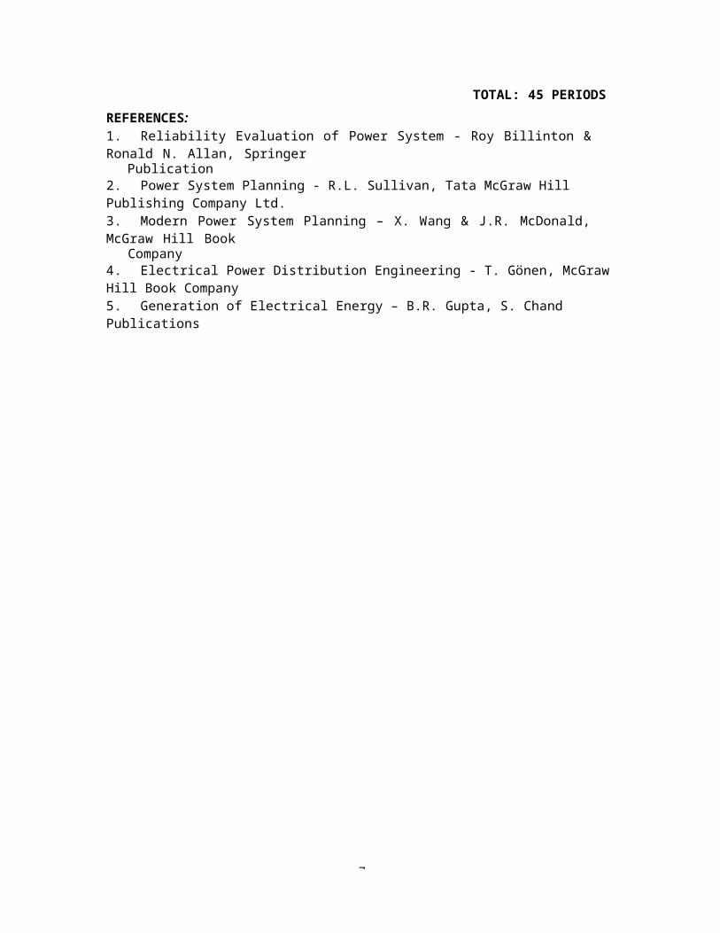
7
TOTAL: 45 PERIODSREFERENCES:1. Reliability Evaluation of Power System - Roy Billinton & Ronald N. Allan, Springer
Publication2. Power System Planning - R.L. Sullivan, Tata McGraw Hill Publishing Company Ltd.3. Modern Power System Planning – X. Wang & J.R. McDonald, McGraw Hill Book
Company4. Electrical Power Distribution Engineering - T. Gönen, McGraw Hill Book Company5. Generation of Electrical Energy – B.R. Gupta, S. Chand Publications
Related Documents

![Me Syllabus Info]](https://static.cupdf.com/doc/110x72/54fb8ab64a795937538b45c7/me-syllabus-info.jpg)