N. Senthil Kumar, M. Saravanan & S. Jeevananthan © Oxford University Press 2013

Welcome message from author
This document is posted to help you gain knowledge. Please leave a comment to let me know what you think about it! Share it to your friends and learn new things together.
Transcript
8/12/2019 354 33 Powerpoint-slides CH14
http://slidepdf.com/reader/full/354-33-powerpoint-slides-ch14 1/96
N. Senthil Kumar,M. Saravanan &
S. Jeevananthan
© Oxford University Press 2013
8/12/2019 354 33 Powerpoint-slides CH14
http://slidepdf.com/reader/full/354-33-powerpoint-slides-ch14 2/96
Addressing modes, Instruction setand Programming of 8086
© Oxford University Press 2013

8/12/2019 354 33 Powerpoint-slides CH14
http://slidepdf.com/reader/full/354-33-powerpoint-slides-ch14 3/96
Addressing modes in8086• Register addressing mode• Immediate addressing mode•
Data memory addressing modes• Program memory addressing modes• Stack memory addressing modes
© Oxford University Press 2013
8/12/2019 354 33 Powerpoint-slides CH14
http://slidepdf.com/reader/full/354-33-powerpoint-slides-ch14 4/96
Register addressingmode• In this addressing mode, the data present in register is
moved or manipulated and the result is stored in register.•
Examples:• MOV AL,BL ; Move content of BL to AL• MOV CX,BX ; Move content of BX to CX• ADD CL,BL ; Add content of CL and BL and store result
in CL• ADC BX,DX ; Add content of BX, carry flag and DX, and
store result in BX
© Oxford University Press 2013
8/12/2019 354 33 Powerpoint-slides CH14
http://slidepdf.com/reader/full/354-33-powerpoint-slides-ch14 5/96
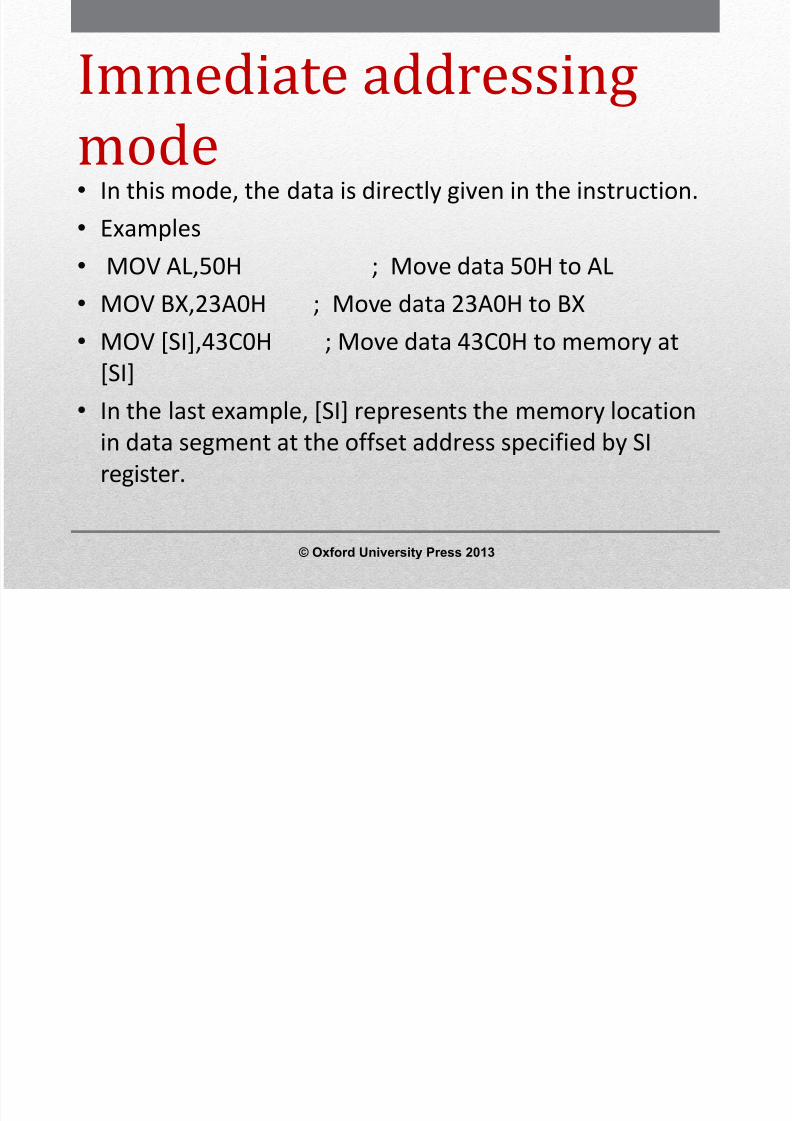
Immediate addressingmode• In this mode, the data is directly given in the instruction.• Examples•
MOV AL,50H ; Move data 50H to AL• MOV BX,23A0H ; Move data 23A0H to BX• MOV [SI],43C0H ; Move data 43C0H to memory at
[SI]•
In the last example, [SI] represents the memory locationin data segment at the offset address specified by SIregister.
© Oxford University Press 2013

8/12/2019 354 33 Powerpoint-slides CH14
http://slidepdf.com/reader/full/354-33-powerpoint-slides-ch14 6/96
Data memory addressingmodes• The term Effective Address (EA) represents the offset
address of the data within a segment which is obtained
by different methods, depending upon the addressingmode that is used in the instruction.
• Let us assume that the various registers in 8086 have thefollowing values stored in them.
© Oxford University Press 2013

8/12/2019 354 33 Powerpoint-slides CH14
http://slidepdf.com/reader/full/354-33-powerpoint-slides-ch14 7/96
Direct Addressing:•
In this mode, the 16 bit offset address of the data within thesegment is directly given in the instruction.• Examples:• a) MOV AL, [1000H]• EA is given within square bracket in the instruction in this addressing
mode and hence EA=1000H in the above instruction. Since thedestination is an 8-bit register (i.e. AL), a byte is taken from memoryat the address given by DS x10H + EA=31000H and stored in AL.
• b) MOV BX,[2000H]• EA=2000H in this instruction. Since the destination is a 16 bit
register (i.e. BX), a word is taken from memory address DSx10H+EA=32000H and stored in BX. (Note: Since a word contains two bytes,the byte present at memory address 32000H and 32001H are movedto BL and BH respectively.)
© Oxford University Press 2013

8/12/2019 354 33 Powerpoint-slides CH14
http://slidepdf.com/reader/full/354-33-powerpoint-slides-ch14 8/96
Base Addressing•
In this mode, the EA is the content of BX or BP register. When BXregister is present in the instruction, data is taken from the datasegment and if BP is present in the instruction, data is taken fromthe stack segment.
• Examples:•
MOV CL,[BX]• EA=(BX)=2000H• Memory address=DSx10+(BX)=32000H. The byte from the memory
address 32000H is read and stored in CL.• MOV DX,[BP]• EA=(BP)=1000H• Memory address=SSx10+(BP)=41000H. The word from the memory
address 41000H is read and stored in DX.
© Oxford University Press 2013
8/12/2019 354 33 Powerpoint-slides CH14
http://slidepdf.com/reader/full/354-33-powerpoint-slides-ch14 9/96
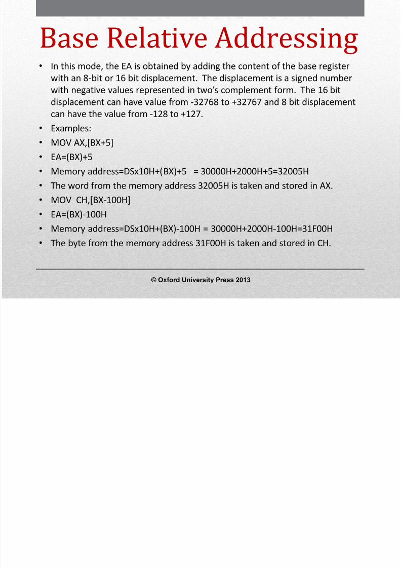
Base Relative Addressing•
In this mode, the EA is obtained by adding the content of the base registerwith an 8-bit or 16 bit displacement. The displacement is a signed numberwith negative values represented in two’s complement form. The 16 bitdisplacement can have value from -32768 to +32767 and 8 bit displacementcan have the value from -128 to +127.
• Examples:• MOV AX,[BX+5]• EA=(BX)+5• Memory address=DSx10H+(BX)+5 = 30000H+2000H+5=32005H• The word from the memory address 32005H is taken and stored in AX.• MOV CH,[BX-100H]• EA=(BX)-100H• Memory address=DSx10H+(BX)-100H = 30000H+2000H-100H=31F00H• The byte from the memory address 31F00H is taken and stored in CH.
© Oxford University Press 2013
8/12/2019 354 33 Powerpoint-slides CH14
http://slidepdf.com/reader/full/354-33-powerpoint-slides-ch14 10/96
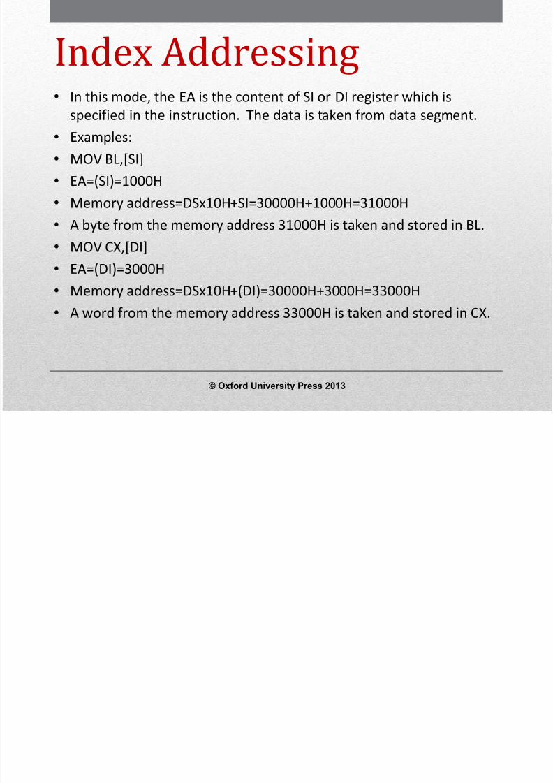
Index Addressing• In this mode, the EA is the content of SI or DI register which is
specified in the instruction. The data is taken from data segment.• Examples:• MOV BL,[SI]• EA=(SI)=1000H• Memory address=DSx10H+SI=30000H+1000H=31000H• A byte from the memory address 31000H is taken and stored in BL.• MOV CX,[DI]• EA=(DI)=3000H• Memory address=DSx10H+(DI)=30000H+3000H=33000H• A word from the memory address 33000H is taken and stored in CX.
© Oxford University Press 2013
8/12/2019 354 33 Powerpoint-slides CH14
http://slidepdf.com/reader/full/354-33-powerpoint-slides-ch14 11/96
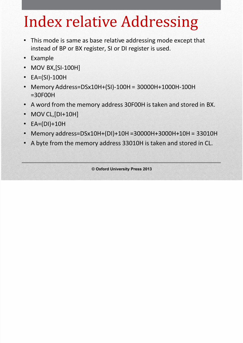
Index relative Addressing•
This mode is same as base relative addressing mode except thatinstead of BP or BX register, SI or DI register is used.• Example• MOV BX,[SI-100H]• EA=(SI)-100H• Memory Address=DSx10H+(SI)-100H = 30000H+1000H-100H
=30F00H• A word from the memory address 30F00H is taken and stored in BX.• MOV CL,[DI+10H]• EA=(DI)+10H• Memory address=DSx10H+(DI)+10H =30000H+3000H+10H = 33010H• A byte from the memory address 33010H is taken and stored in CL.
© Oxford University Press 2013

8/12/2019 354 33 Powerpoint-slides CH14
http://slidepdf.com/reader/full/354-33-powerpoint-slides-ch14 12/96
Base plus index Addressing
• In this mode, the EA is obtained by adding the content of a baseregister and index register.
• Example•
MOV AX,[BX+SI]• EA=(BX)+(SI)• Memory address=DSx10H+(BX)+(SI)=30000H+2000H+1000H• =33000H• A word from the memory address 33000H is taken and stored in AX.• Base relative, index relative and base plus index addressing modes
are used to access a byte or word type data from a table of data oran array of data stored in data segment one by one.
© Oxford University Press 2013

8/12/2019 354 33 Powerpoint-slides CH14
http://slidepdf.com/reader/full/354-33-powerpoint-slides-ch14 13/96
Base Relative plus indexAddressing• In this mode, the EA is obtained by adding the content of a base register, an index
and a displacement.• Example:• MOV CX,[BX+SI+50H]• EA= (BX)+(SI)+50H• Memory address=DSx10H+(BX)+(SI)+50H• =30000H+2000H+1000H+50H• =33050H• A word from the memory address 33050H is taken and stored in CX.• Base relative plus index addressing is used to access a byte or a word in a particular
record of a particular file in memory. A particular application program may process
many files stored in the data segment.• Each file contains many records and a record contains few bytes or words of data. In
base relative plus index addressing, base register may be used to hold the offsetaddress of a particular file in the data segment; index register may be used to holdthe offset address of a particular record within that file and the relative value is usedto indicate the offset address of particular byte or word within that record.
© Oxford University Press 2013

8/12/2019 354 33 Powerpoint-slides CH14
http://slidepdf.com/reader/full/354-33-powerpoint-slides-ch14 14/96
Program memory addressing
modes• Program memory addressing modes are used with JMP and CALL
instructions and consist of three distinct forms namely direct, relative andindirect.
•
Direct Addressing: The direct program memory addressing stores both thesegment and offset address where the control has to be transferred withthe opcode.
• The above instruction is equivalent to JMP 32000H.• When it is executed, the 16 bit offset value 2000H is loaded in IP register
and the 16 bit segment value 3000H is loaded in CS.• When the microprocessor calculates the memory address from where it has
to fetch an instruction using the relation CSx10H+IP, the address 32000H willbe obtained using the above CS and IP values.
© Oxford University Press 2013

8/12/2019 354 33 Powerpoint-slides CH14
http://slidepdf.com/reader/full/354-33-powerpoint-slides-ch14 15/96
Relative Addressing• The term relative here means relative to the instruction pointer (IP). Relative JMP and CALL
instructions contain either an 8 bit or a 16 bit signed displacement that is added to the currentinstruction pointer and based on the new value of IP thus obtained, the address of the nextinstruction to be executed is calculated using the relation CSx10H+IP.
• The 8-bit or 16 bit signed displacement which allows a forward memory reference or a reversememory reference. A one byte displacement is used in short jump and call instructions, and a twobyte displacement is used in near jump and call instructions. Both types are considered
intrasegment jumps since the program control is transferred anywhere within the current codesegment.
• An 8 bit displacement has a jump range of between +127 and -128 bytes from the next instructionwhile a 16 bit displacement has a jump range of between -32768 and +32767 bytes from the nextinstruction following the jump instruction in the program. The opcode of relative short jump andnear jump instructions are EBH and E9H respectively.
• While using assembler to develop 8086 program, the assembler directive SHORT and NEAR PTR is
used to indicate short jump and near jump instruction respectively.• Examples:• a) JMP SHORT OVER• b) JMP NEAR PTR FIND• In the above examples, OVER and FIND are the label of memory locations that are present in the
same code segment in which the above instructions are present.
© Oxford University Press 2013

8/12/2019 354 33 Powerpoint-slides CH14
http://slidepdf.com/reader/full/354-33-powerpoint-slides-ch14 16/96
Indirect Addressing• The indirect jump or CALL instructions use either any 16 bit register
(AX,BX,CX,DX,SP,BP,SI or DI) or any relative register ([BP],[BX],[DI] or [SI]) orany relative register with displacement. The opcode of indirect jumpinstruction is FFH. It can be either intersegment indirect jump orintrasegment indirect jump instruction
• If a 16 bit register holds the jump address of in a indirect JMP instruction,
the jump is near. If the CX register contains 2000H and JMP CX instructionpresent in a code segment is executed, the microprocessor jumps to offsetaddress 2000H in the current code segment to take the next instruction forexecution (This is done by loading the IP with the content of CX withoutchanging the content of CS).
• When the instruction JMP [DI] is executed, the microprocessor first reads aword in the current data segment from the offset address specified by DIand puts that word in IP register. Now using this new value of IP, 8086calculates the address of the memory location where it has to jump usingthe relation CSx10H+IP.
© Oxford University Press 2013
8/12/2019 354 33 Powerpoint-slides CH14
http://slidepdf.com/reader/full/354-33-powerpoint-slides-ch14 17/96
Stack memory addressing
mode• The stack holds data temporarily and also stores return address for procedures andinterrupt service routines. The stack memory is a last-in, first-out (LIFO) memory.Data are placed into the stack using PUSH instruction and taken out from the stackusing POP instruction. The CALL instruction uses the stack to hold the return addressfor procedures and RET instruction is used to remove return address from stack.
• The stack segment is maintained by two registers: the stack pointer (SP) and the stacksegment register (SS). Always a word is entered into stack. Whenever a word of datais pushed into the stack, the higher-order 8 bits of the word are placed in the memorylocation specified by SP-1 (i.e. at address SSx10H + SP-1)and the lower-order 8 bits ofthe word are placed in the memory location specified by SP-2 in the current stacksegment (SS) (i.e. at address SSx10H + SP-2). The SP is then decremented by 2. Thedata pushed into the stack may be either the content of a 16 bit register or segmentregister or 16 bit data in memory.
• Since SP gets decremented for every push operation, the stack segment is said to begrowing downwards as for successive push operations, the data are stored in lowermemory addresses in stack segment. Due to this, the SP is initialized with highestoffset address according to the requirement, at the beginning of the program.
© Oxford University Press 2013
8/12/2019 354 33 Powerpoint-slides CH14
http://slidepdf.com/reader/full/354-33-powerpoint-slides-ch14 18/96
Segment Override Prefix:•
The segment override prefix which can be added to almost any instructionin any memory related addressing mode, allows the programmer to deviatefrom the default segment and offset register mechanism. The segmentoverride prefix is an additional byte that appears the front of an instructionto select an alternate segment register. The jump and call instructionscannot be prefixed with the segment override prefix since they use only
code segment register (CS) for address generation.• Example:• MOV AX,[BP] instruction accesses data within stack segment by default
since BP is the offset register for stack segment. But if the programmerwants to get data from data segment using BP as offset register in the aboveinstruction, then the instruction is modified as
• MOV AX, DS:[BP]
© Oxford University Press 2013

8/12/2019 354 33 Powerpoint-slides CH14
http://slidepdf.com/reader/full/354-33-powerpoint-slides-ch14 19/96
Instruction set of 8086
• The instructions of 8086 are classified into data transfer,arithmetic, logical, flag manipulation, control transfer,
shift/rotate, string and machine control instructions.• Data transfer instructions:• The data transfer instructions include MOV, PUSH, POP,
XCHG, XLAT, IN, OUT, LEA, LDS, LES, LSS, LAHF and SAHF
© Oxford University Press 2013
8/12/2019 354 33 Powerpoint-slides CH14
http://slidepdf.com/reader/full/354-33-powerpoint-slides-ch14 20/96
Data transfer instructions
• MOV: MOV instruction copies a word or byte of data from aspecified source to a specified destination. The destination can be aregister or a memory location. The source can be a register or amemory location or an immediate number. The general format ofMOV instruction is
• MOV Destination, Source• Examples:• MOV BL, 50H ; Move immediate data 50H to BL•
MOV CX, [BX] ; Copy word from memory at [BX] to CX• MOV AX, CX ; Copy contents of CX to AX• Note: [BX] indicates the memory location at offset address specified
by BX in data segment.
© Oxford University Press 2013
8/12/2019 354 33 Powerpoint-slides CH14
http://slidepdf.com/reader/full/354-33-powerpoint-slides-ch14 21/96
Data transfer
instructions• PUSH: PUSH instruction is used to store the word in a
register or a memory location into stack as explained in
stack addressing modes. SP is decremented by 2 afterexecution of PUSH.• Examples:• PUSH CX; PUSH CX content in stack•
PUSH DS; PUSH DS content in stack• PUSH [BX]; PUSH word in memory at [BX] into stack
© Oxford University Press 2013

8/12/2019 354 33 Powerpoint-slides CH14
http://slidepdf.com/reader/full/354-33-powerpoint-slides-ch14 22/96
Data transfer instructions
• POP: POP instruction copies the top word from the stack to adestination specified in the instruction. The destination can be ageneral purpose register, a segment register or a memory location.
After the word is copied to the specified destination, the SP isincremented by 2 to point to the next word in the stack.• Examples:• POP BX ; Pop BX content from the stack• POP DS ; Pop DS content from the stack• POP [SI] ; Pop a word from the stack and store it in memory at [SI]• Note: [SI] indicates the memory location in data segment at offset
address specified by SI.
© Oxford University Press 2013
8/12/2019 354 33 Powerpoint-slides CH14
http://slidepdf.com/reader/full/354-33-powerpoint-slides-ch14 23/96
Data transfer instructions• XCHG: The XCHG instruction exchanges the contents of a register with the contents
of a memory location. It cannot exchange directly the contents of two memorylocations. The source and destination must both be words or they must both bebytes. The segment registers cannot be used in this instruction.
• Examples:• XCHG AL, BL; Exchanges content of AL and BL• XCHG CX, BX; Exchanges content of CX and BX• XCHG AX, [BX]; Exchanges content of AX with content of memory at [BX]
• XLAT: The XLAT instruction is used to translate a byte in AL from one code to anothercode. The instruction replaces a byte in the AL register with a byte in memory at [BX],
which is data in a lookup table present in memory.• Before XLAT is executed, the lookup table containing the desired codes must be put in
data segment and the offset address of the starting location of the lookup table isstored in BX. The code byte to be translated is put in AL. When XLAT is nowexecuted, it adds the content of the AL with BX to find the offset address of the datain the above lookup table and the byte in that offset address is copied to AL.
© Oxford University Press 2013

8/12/2019 354 33 Powerpoint-slides CH14
http://slidepdf.com/reader/full/354-33-powerpoint-slides-ch14 24/96
Data transfer instructions• IN: The IN instruction copies data from a port to AL or AX register. If an 8-bit port is
read, the data is stored in AL and if a 16 bit port is read, the data is stored in AX. TheIN instruction has two formats namely fixed port and variable port.
• For the fixed port type IN instruction, the 8-bit address of a port is specified directly inthe instruction. With this form, anyone of 256 possible ports can be addressed.
• Examples:• IN AL, 80H; Input a byte from the port with address 80H to AL• IN AX, 40H; Input a word from port with address 40H to AX• For the variable port type IN instruction, the port address is loaded into DX register
before the IN instruction. Since DX is a 16 bit register, the port address can be anynumber between 0000H and FFFFH. Hence up to 65536 ports are addressable in thismode. The following example shows a part of the program having IN instruction andthe operations done when the instructions are executed are given in the
corresponding comment field.• Examples:• MOV DX, 0FE50H ; Initialize DX with port address of FE50H• IN AL, DX ; Input a byte from 8-bit port with port address FE50H into AL• IN AX, DX ; Input a word from 16-bit port with port address FE50H into AX
© Oxford University Press 2013

8/12/2019 354 33 Powerpoint-slides CH14
http://slidepdf.com/reader/full/354-33-powerpoint-slides-ch14 25/96
Data transfer instructions• OUT: The OUT instruction transfers a byte from AL or a word from
AX to the specified port. Similar to IN instruction, OUT instructionhas two forms namely fixed port and variable port.
• Examples for fixed port OUT instruction:•
OUT 48H,AL ; Send the content of AL to port with address 48H• OUT 0F0H,AX ; Send the content of AX to port with address FOH• Example for variable port OUT instruction:• The following example shows a part of the program having OUT
instruction and the operations done when the instructions are
executed are given in the corresponding comment field.• MOV DX, 1234H; Load port address 1234H in DX• OUT DX, AL; Send the content of AL to port with address 1234H• OUT DX,AX; Send the content of AX to port with address 1234H
© Oxford University Press 2013

8/12/2019 354 33 Powerpoint-slides CH14
http://slidepdf.com/reader/full/354-33-powerpoint-slides-ch14 26/96
Data transfer instructions• LEA: Load Effective Address• The general format of LEA instruction is• LEA register, source• This instruction determines the offset address of the variable or
memory location named as the source and puts this offset addressin the indicated 16 bit register.
• Examples:• LEA BX, COST; Load BX with offset address of COST in data segment
where• COST is the name assigned to a memory location in data segment.• LEA CX, [BX][SI]; Load CX with the value equal to (BX)+(SI) where (BX)
and• (SI) represents content of BX and SI respectively.
© Oxford University Press 2013
8/12/2019 354 33 Powerpoint-slides CH14
http://slidepdf.com/reader/full/354-33-powerpoint-slides-ch14 27/96
Data transfer instructions
• LDS: Load register and DS with words from memory• The general form of this instruction is• LDS register, memory address of first word• The LDS instruction copies a word from the memory location
specified in the instruction into the register and then copies a wordfrom the next memory location into the DS register.
• LDS is useful for initializing SI and DS registers at the start of a stringbefore using one of the String instructions.
• Example:• LDS SI,[2000H]; Copy content of memory at offset address 2000H in
data segment to lower byte of SI, content of 2001H to higher byte ofSI. Copy content at offset address 2002H in data segment to lowerbyte of DS and 2003H to higher byte of DS.
© Oxford University Press 2013
8/12/2019 354 33 Powerpoint-slides CH14
http://slidepdf.com/reader/full/354-33-powerpoint-slides-ch14 28/96
Data transfer instructions• LES, LSS: LES and LSS instructions are similar to LDS
instruction except that instead of DS register, ES and SSregisters are loaded respectively along with the registerspecified in the instruction.
• LAHF: This instruction copies the low byte of flag registerinto AH.
• SAHF: Store content of AH in the low byte of flagregister.
• Except SAHF and POPF instructions, all other datatransfer instructions do not affect flag register.
© Oxford University Press 2013

8/12/2019 354 33 Powerpoint-slides CH14
http://slidepdf.com/reader/full/354-33-powerpoint-slides-ch14 29/96
Arithmetic instructions• ADD: The general format of ADD instruction is• ADD destination, source• The data from the source and destination are added and the result is placed in the
destination. The source may be an immediate number, a register or a memorylocation. The destination can be a register or memory location. But the source anddestination cannot both be memory locations. The data from the source anddestination must be of the same type either bytes or words.
• Examples:• ADD BL,80H; Add immediate data 80H to BL• ADD CX,12B0H; Add immediate data 12B0H to CX• ADD AX,CX; Add content of AX and CX and store result in AX• ADD AL,[BX]; Add content of AL and the byte from memory at [BX] and store result in
AL.• ADD CX,[SI]; Add content of CX and the word from memory at [SI] and store result in
CX.• ADD [BX],DL; Add content of DL with the byte from memory at [BX] and store result
in memory at [BX].• The flags AF, CF, OF, PF, SF and ZF flags are affected by the execution of ADD
instruction
© Oxford University Press 2013
8/12/2019 354 33 Powerpoint-slides CH14
http://slidepdf.com/reader/full/354-33-powerpoint-slides-ch14 30/96
8/12/2019 354 33 Powerpoint-slides CH14
http://slidepdf.com/reader/full/354-33-powerpoint-slides-ch14 31/96
Arithmetic instructions• SBB: Subtract with Borrow• The general form of this instruction is• SBB destination, source• SBB instruction subtracts the content of source and
content of carry flag from the content of destination andstores the result in destination. The rules for the sourceand destination are same as that of SUB instruction. AF,CF, OF, PF, SF and ZF are affected by this instruction.
© Oxford University Press 2013
8/12/2019 354 33 Powerpoint-slides CH14
http://slidepdf.com/reader/full/354-33-powerpoint-slides-ch14 32/96
Arithmetic instructions• INC: The increment (INC) instruction adds 1 to a specified register or
to a memory location. The data incremented may be a byte orword. Carry flag is not affected by this instruction. AF, OF, PF, SF andZF flags are affected.
• Examples:• INC CL; Increment content of CL by 1• INC AX; Increment content of AX by 1• INC BYTE PTR [BX]; Increment byte in memory at [BX] by 1• INC WORD PTR [SI]; Increment word in memory at [SI] by 1•
In the above examples, the term BYTE PTR and WORD PTR areassembler directives which are used to specify the type of data (byteor word respectively) to be incremented in memory.
© Oxford University Press 2013
8/12/2019 354 33 Powerpoint-slides CH14
http://slidepdf.com/reader/full/354-33-powerpoint-slides-ch14 33/96
Arithmetic instructions• DEC: The decrement (DEC) instruction subtracts 1 from the specified
register or memory location. The data decremented may be a byte or word.CF is not affected and AF,OF, PF, SF and ZF flags are affected by thisinstruction.
• NEG: The negate (NEG) instruction replaces the byte or word in thespecified register or memory location by its 2’s complement (i.e. changingthe sign of the data). CF,AF, SF, PF, ZF and OF flags are affected by thisinstruction.
• Examples:• NEG AL; Take 2’s complement of the data in AL and store it in AL • NEG CX; Take 2’s complement of the data in CX and store it in CX • NEG BYTE PTR*BX+; Take 2’s complement of the byte in memory at *BX+ and
store result in the same place.• NEG WORD PTR*SI+; Take 2’s complement of the word in memory at *SI+ and
store result in the same place.
© Oxford University Press 2013
8/12/2019 354 33 Powerpoint-slides CH14
http://slidepdf.com/reader/full/354-33-powerpoint-slides-ch14 34/96
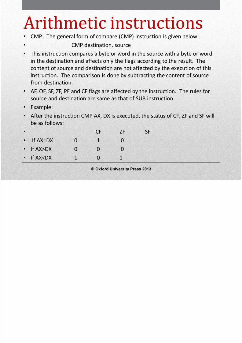
Arithmetic instructions• CMP: The general form of compare (CMP) instruction is given below:• CMP destination, source• This instruction compares a byte or word in the source with a byte or word
in the destination and affects only the flags according to the result. Thecontent of source and destination are not affected by the execution of thisinstruction. The comparison is done by subtracting the content of sourcefrom destination.
• AF, OF, SF, ZF, PF and CF flags are affected by the instruction. The rules forsource and destination are same as that of SUB instruction.
• Example:• After the instruction CMP AX, DX is executed, the status of CF, ZF and SF will
be as follows:• CF ZF SF• If AX=DX 0 1 0• If AX>DX 0 0 0• If AX<DX 1 0 1
© Oxford University Press 2013
8/12/2019 354 33 Powerpoint-slides CH14
http://slidepdf.com/reader/full/354-33-powerpoint-slides-ch14 35/96
Arithmetic instructions• MUL: The multiply (MUL) instruction is used for multiplying two unsigned bytes or
words. The general form of MUL instruction is• MUL Source• The source can be byte or word from a register or memory location which is
considered as the multiplier. The multiplicand is taken by default from AL or AX forbyte or word type data respectively. The result of multiplication is stored in AX or DX-AX (i.e. Most significant word of result in DX and least significant word of result in AX)for byte or word type data respectively. (Note: Multiplying two 8 bit data gives 16 bitresult and multiplying two 16 bit data gives 32 bit result).
• Examples:• MUL CH; Multiply AL and CH and store result in AX• MUL BX; Multiply AX and BX and store result in DX-AX• MUL BYTE PTR [BX]; multiply AL with the byte in memory at [B X] and store
result in DX-AX• If the most significant byte of the 16 bit result is 00H or the most significant word of a
32 bit result is 0000h, both CF and OF will both be 0s. Checking these flags allows usto decide whether the leading 0s in the result have to be discarded or not. AF, PF, SFand ZF flags are undefined (i.e. some random number will be stored in these bits)after the execution of MUL instruction
© Oxford University Press 2013

8/12/2019 354 33 Powerpoint-slides CH14
http://slidepdf.com/reader/full/354-33-powerpoint-slides-ch14 36/96
Arithmetic instructions• IMUL: The IMUL instruction is used for multiplying signed byte or word in a register
or memory location with AL or AX respectively and stores the result in AX or DX-AXrespectively. If the magnitude of the result does not require all the bits of thedestination, the unused bits are filled with copies of the sign bit.
• If the upper byte of a 16 bit result or upper word of a 32 bit result contains onlycopies of the sign bit (all 0s or all 1s) then CF and OF will both be 0 otherwise bothwill be 1. AF, PF, SF and ZF are undefined after IMUL.
• To multiply a signed byte by a signed word, the byte is moved into a word locationand the upper byte of the word is filled with the copies of the sign bit. If the byte ismoved into AL, by using the CBW (Convert Byte to Word) instruction, the sign bit in ALis extended into all the bits of AH. Thus AX contains the 16 bit sign extended word.
• Examples:• IMUL BL; multiply AL with BL and store result in AX• IMUL AX; multiply AX and AX and store result in DX-AX• IMUL BYTE PTR [BX]; multiply AL with byte from memory at [BX] and store result in AX• IMUL WORD PTR [SI]; Multiply AX with word from memory at [SI] and store result in
DX-AX
© Oxford University Press 2013

8/12/2019 354 33 Powerpoint-slides CH14
http://slidepdf.com/reader/full/354-33-powerpoint-slides-ch14 37/96
Arithmetic instructions• DIV: The divide (DIV) instruction is used for dividing unsigned data.
The general form of DIV instruction is• DIV source• Where source is the divisor and it can be a byte or word in a register
or memory location. The dividend is taken by default from AX andDX-AX for byte or word type data division respectively.
• Examples• DIV DL; Divide word in AX by byte in DL. Quotient is stored in AL and
remainder is stored in AH• DIV CX; Divide double word (32 bits) in DX-AX by word in CX.
Quotient is stored in AX and remainder is stored in DX• DIV BYTE PTR [BX]; Divide word in AX by byte from memory at [BX].
Quotient is stored in AL and remainder is stored in AH.
© Oxford University Press 2013
8/12/2019 354 33 Powerpoint-slides CH14
http://slidepdf.com/reader/full/354-33-powerpoint-slides-ch14 38/96
Arithmetic instructions• IDIV: The IDIV instruction is used for dividing signed data. The general form
and the rules for IDIV instruction are same as DIV instruction. The quotientwill be a signed number and the sign of the remainder is same as the sign ofthe dividend.
• To divide a signed byte by a signed byte, the dividend byte is put in AL andusing CBW (Convert Byte to Word) instruction, the sign bit of the data in ALis extended to AH and thereby the byte in AL is converted to signed word inAX. To divide a signed word by a signed word, the dividend byte is put in AXand using CWD (Convert Word to Double word) instruction, the sign bit ofthe data in AX is extended to DX and thereby the word in AX is converted tosigned double word in DX-AX.
• If an attempt is made to divide by 0 or if the quotient is too large or two low
to fit in AL or AX for 8 or 16 bit division respectively (i.e. either when theresult is greater than +127 decimal in 8 bit division or +32767 decimal in 16bit division or if the result is less than -128 decimal in 8 bit division or -32767 decimal in 16 bit division), the 8086 automatically generate a type 0interrupt. All flags are undefined after a DIV instruction.
© Oxford University Press 2013
8/12/2019 354 33 Powerpoint-slides CH14
http://slidepdf.com/reader/full/354-33-powerpoint-slides-ch14 39/96
Arithmetic instructions• DAA: Decimal Adjust AL after BCD addition• This instruction is used to get the result of adding two packed BCD numbers
(two decimal digits are represented in 8 bits) to be a BCD number. Theresult of addition must be in AL for DAA to work correctly. If the lowernibble (4 bits) in AL is greater than 9 after addition or AF flag is set by theaddition then the DAA will add 6 to the lower nibble in AL. If the result inthe upper nibble of AL is now greater than 9 or if the carry flag is set by theaddition, then the DAA will add 60H to AL.
• Examples:• Let AL=0101 1000=58 BCD• CL=0011 0101=35 BCD• Consider the execution of the following instructions:• ADD AL, CL; AL=10001101=8DH and AF=0 after execution• DAA - Add 0110 (decimal 6) to AL since lower nibble in AL is greater than 9• AL=10010011= 93 BCD and CF=0• Therefore the result of addition is 93 BCD.
© Oxford University Press 2013

8/12/2019 354 33 Powerpoint-slides CH14
http://slidepdf.com/reader/full/354-33-powerpoint-slides-ch14 40/96
Arithmetic instructions•
DAS: Decimal Adjust after BCD subtraction• DAS is used to get the result is in correct packed BCD form after subtracting
two packed BCD numbers. The result of the subtraction must be in AL forDAS to work correctly. If the lower nibble in AL after a subtraction is greaterthan 9 or the AF was set by subtraction then the DAS will subtract 6 fromthe lower nibble of AL. If the result in the upper nibble is now greater than
9 or if the carry flag was set, the DAS will subtract 60H from AL.• Examples:• Let AL=86 BCD=1000 0110• CH=57 BCD=0101 0111• Consider the execution of the following instructions:• SUB AL, CH; AL=0010 1111=2FH and CF=0 after execution• DAS; Lower nibble of result is 1111, so DAS subtracts 06H from AL to make• AL=0010 1001=29 BCD and CF=0 to indicate there is no borrow.• The result is 29 BCD.
© Oxford University Press 2013
8/12/2019 354 33 Powerpoint-slides CH14
http://slidepdf.com/reader/full/354-33-powerpoint-slides-ch14 41/96
Arithmetic instructions• AAA:• AAA (ASCII Adjust after Addition) instruction must always follow the addition of two
unpacked BCD operands in AL. When AAA is executed, the content of AL is changedto a valid unpacked BCD number and clears the top 4 bits of AL. The CF is set and AHis incremented if a decimal carry out from AL is generated.
• Example:• Let AL=05 decimal=0000 0101• BH=06 decimal=0000 0100• AH=00H• Consider the execution of the following instructions:• ADD AL, BH ; AL=0BH=11 decimal and CF=0• AAA ; AL=01 and AH=01 and CF=1• Since 05+06=11(decimal)=0101 H stored in AX in unpacked BCD form.• When this result is to be sent to the printer, the ASCII code of each decimal digit is
easily formed by adding 30H to each byte.
© Oxford University Press 2013

8/12/2019 354 33 Powerpoint-slides CH14
http://slidepdf.com/reader/full/354-33-powerpoint-slides-ch14 42/96
Arithmetic instructions• AAS: ASCII Adjust after Subtraction• This instruction always follows the subtraction of one unpacked BCD operand from another
unpacked BCD operand in AL. It changes the content of AL to a valid unpacked BCD number andclears the top 4 bits of AL. The CF is set and AH is decremented if a decimal carry occurred.
• Example:• Let AL=09 BCD=0000 1001• CL=05 BCD =0000 0101•
AH=00H• Consider the execution of the following instructions:• SUB AL, CL; AL=04 BCD• AAS ; AL=04 BCD and CF=0• ; AH=00H• • AAA and AAS affect AF and CF flags and OF, PF, SF and ZF are left undefined. Another salient
feature of the above two instructions are that the input data used in the addition or subtractioncan be even in ASCII form of the unpacked decimal number and still we get the result in ordinaryunpacked decimal number form and by adding 30H to the result , again we get ASCII form of theresult.
© Oxford University Press 2013
8/12/2019 354 33 Powerpoint-slides CH14
http://slidepdf.com/reader/full/354-33-powerpoint-slides-ch14 43/96
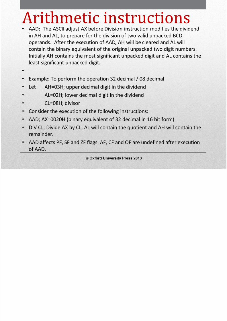
Arithmetic instructions• AAD: The ASCII adjust AX before Division instruction modifies the dividend
in AH and AL, to prepare for the division of two valid unpacked BCD
operands. After the execution of AAD, AH will be cleared and AL willcontain the binary equivalent of the original unpacked two digit numbers.Initially AH contains the most significant unpacked digit and AL contains theleast significant unpacked digit.
• •
Example: To perform the operation 32 decimal / 08 decimal• Let AH=03H; upper decimal digit in the dividend• AL=02H; lower decimal digit in the dividend• CL=08H; divisor• Consider the execution of the following instructions:•
AAD; AX=0020H (binary equivalent of 32 decimal in 16 bit form)• DIV CL; Divide AX by CL; AL will contain the quotient and AH will contain the
remainder.• AAD affects PF, SF and ZF flags. AF, CF and OF are undefined after execution
of AAD.
© Oxford University Press 2013
8/12/2019 354 33 Powerpoint-slides CH14
http://slidepdf.com/reader/full/354-33-powerpoint-slides-ch14 44/96

8/12/2019 354 33 Powerpoint-slides CH14
http://slidepdf.com/reader/full/354-33-powerpoint-slides-ch14 45/96
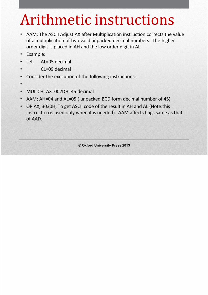
Logical Instructions• AND: The AND instruction perform logical AND operation between the
corresponding bits in the source and destination and stores the result in thedestination. Both the data can be either bytes or words. The general formof AND instruction is
• AND destination, Source• The rules for destination and source for AND instruction are same as that of
ADD instruction. CF and OF are both 0 after AND. PF, SF and ZF are updatedafter execution of AND instruction. AF is undefined. PF has meaning onlyfor ANDing 8-bit operand.
• OR: The OR instruction perform logical OR operation between thecorresponding bits in the source and destination and stores the result in thedestination. Both the data can be either bytes or words. The general formof OR instruction is
• OR destination, Source• The rules for the source and destination and the way flags are affected for
OR instruction are same as that of AND instruction.
© Oxford University Press 2013
8/12/2019 354 33 Powerpoint-slides CH14
http://slidepdf.com/reader/full/354-33-powerpoint-slides-ch14 46/96
8/12/2019 354 33 Powerpoint-slides CH14
http://slidepdf.com/reader/full/354-33-powerpoint-slides-ch14 47/96
Logical Instructions• TEST: This instruction ANDs the content of a source byte or word
with the content of the specified destination byte or wordrespectively. Flags are updated, but neither operand is changed.The TEST instruction is often used to set flags before a conditional jump instruction. The general form of TEST instruction is
• TEST destination, source• The rules for the source and destination are same as that of AND
instruction and the way flag are affected is also same as that of ANDinstruction.
• Example:•
Let AL=0111 1111 =7FH• TEST AL, 80H; AL=7FH (unchanged)• ZF=1 since (AL) AND (80H)=00H; SF=0; PF=1
© Oxford University Press 2013
8/12/2019 354 33 Powerpoint-slides CH14
http://slidepdf.com/reader/full/354-33-powerpoint-slides-ch14 48/96
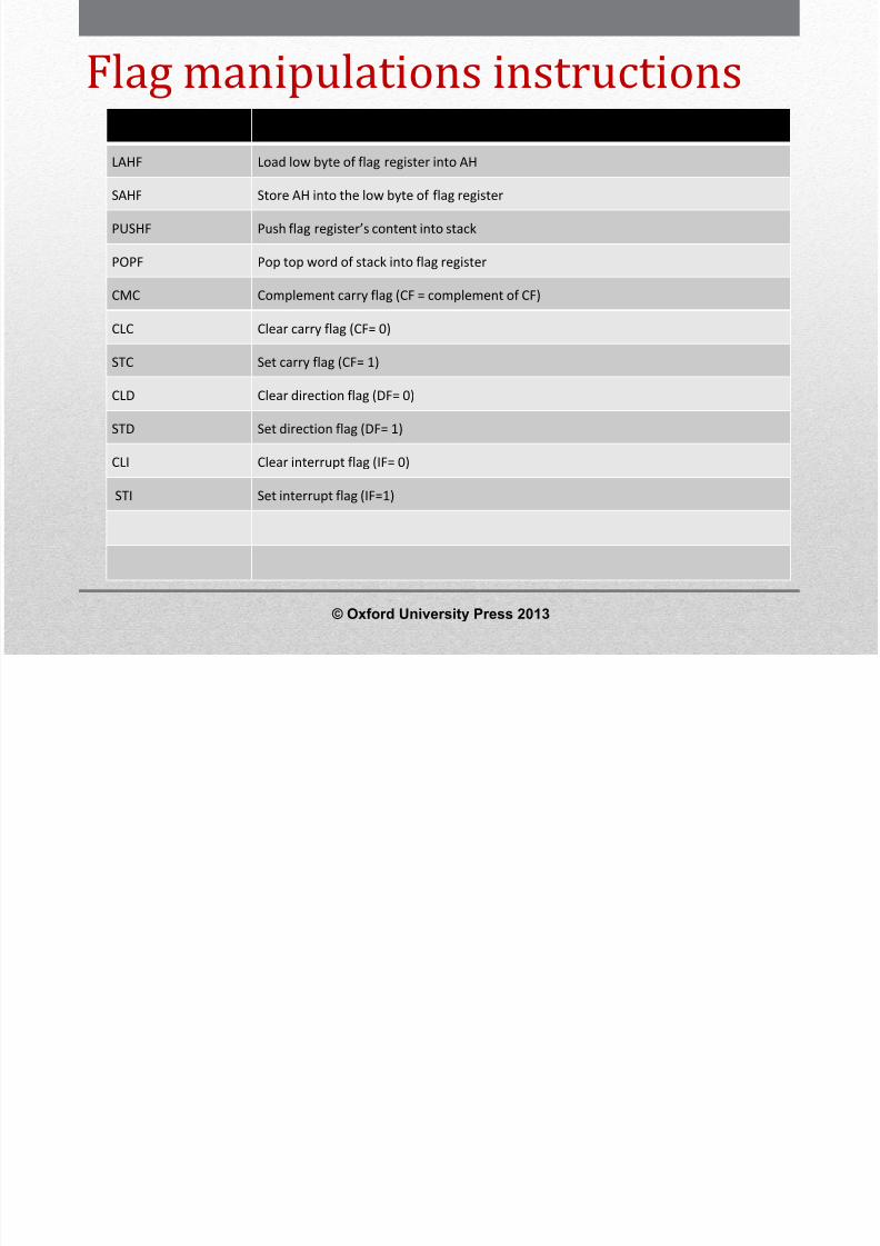
Flag manipulations instructionsMnemonics Function
LAHF Load low byte of flag register into AH
SAHF Store AH into the low byte of flag register
PUSHF Push flag register’s content into stack
POPF Pop top word of stack into flag register
CMC Complement carry flag (CF = complement of CF)
CLC Clear carry flag (CF= 0)
STC Set carry flag (CF= 1)
CLD Clear direction flag (DF= 0)
STD Set direction flag (DF= 1)
CLI Clear interrupt flag (IF= 0) STI Set interrupt flag (IF=1)
© Oxford University Press 2013
8/12/2019 354 33 Powerpoint-slides CH14
http://slidepdf.com/reader/full/354-33-powerpoint-slides-ch14 49/96
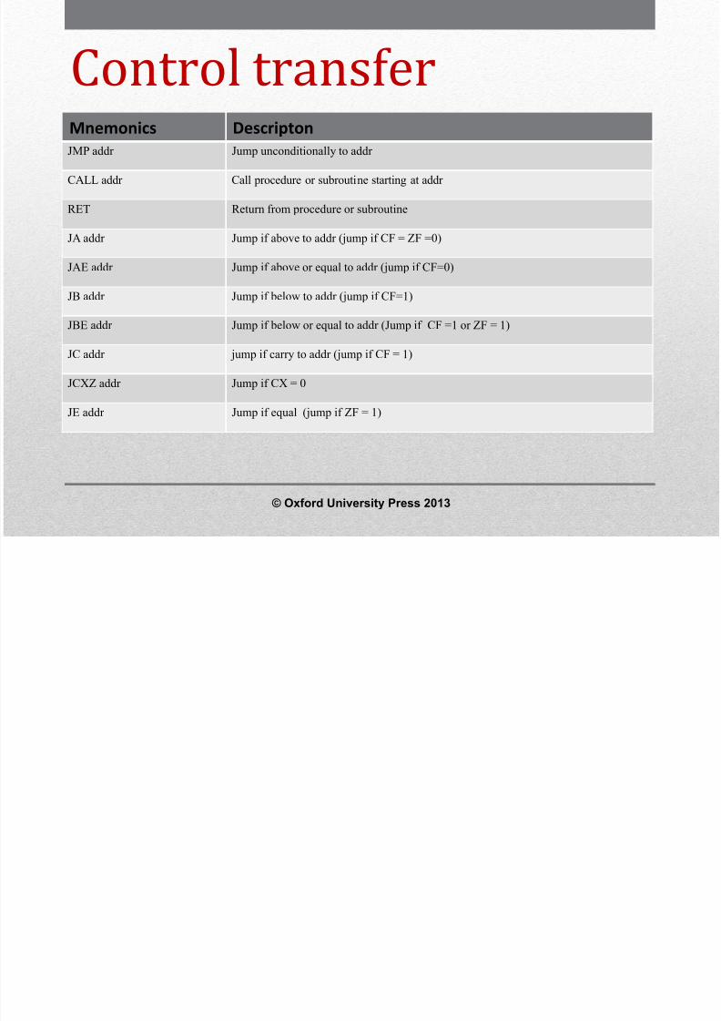
Control transfer
instructionsMnemonics DescriptonJMP addr Jump unconditionally to addr
CALL addr Call procedure or subroutine starting at addr
RET Return from procedure or subroutine
JA addr Jump if above to addr (jump if CF = ZF =0)
JAE addr Jump if above or equal to addr (jump if CF=0)
JB addr Jump if below to addr (jump if CF=1)
JBE addr Jump if below or equal to addr (Jump if CF =1 or ZF = 1)
JC addr jump if carry to addr (jump if CF = 1)
JCXZ addr Jump if CX = 0
JE addr Jump if equal (jump if ZF = 1)
© Oxford University Press 2013
8/12/2019 354 33 Powerpoint-slides CH14
http://slidepdf.com/reader/full/354-33-powerpoint-slides-ch14 50/96
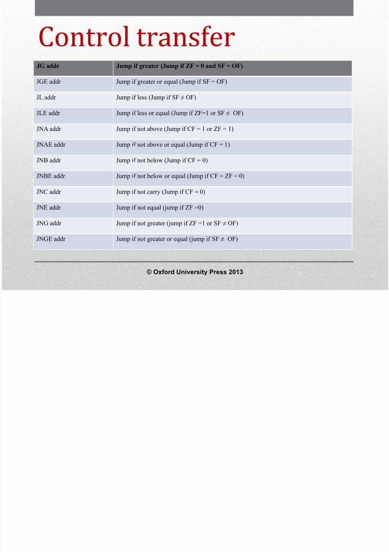
Control transfer
instructionsJG addr Jump if greater (Jump if ZF = 0 and SF = OF)
JGE addr Jump if greater or equal (Jump if SF = OF)
JL addr Jump if less (Jump if SF ≠ OF)
JLE addr Jump if less or equal (Jump if ZF=1 or SF ≠ OF)
JNA addr Jump if not above (Jump if CF = 1 or ZF = 1)
JNAE addr Jump if not above or equal (Jump if CF = 1)
JNB addr Jump if not below (Jump if CF = 0)
JNBE addr Jump if not below or equal (Jump if CF = ZF = 0)
JNC addr Jump if not carry (Jump if CF = 0)
JNE addr Jump if not equal (jump if ZF =0)
JNG addr Jump if not greater (jump if ZF =1 or SF ≠ OF)
JNGE addr Jump if not greater or equal (jump if SF ≠ OF)
© Oxford University Press 2013
8/12/2019 354 33 Powerpoint-slides CH14
http://slidepdf.com/reader/full/354-33-powerpoint-slides-ch14 51/96
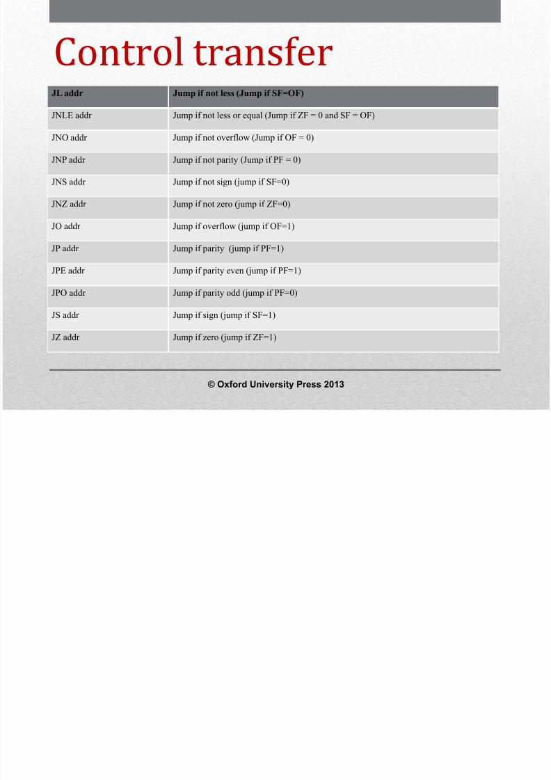
Control transfer
instructionsJL addr Jump if not less (Jump if SF=OF)
JNLE addr Jump if not less or equal (Jump if ZF = 0 and SF = OF)
JNO addr Jump if not overflow (Jump if OF = 0)
JNP addr Jump if not parity (Jump if PF = 0)
JNS addr Jump if not sign (jump if SF=0)
JNZ addr Jump if not zero (jump if ZF=0)
JO addr Jump if overflow (jump if OF=1)
JP addr Jump if parity (jump if PF=1)
JPE addr Jump if parity even (jump if PF=1)
JPO addr Jump if parity odd (jump if PF=0)
JS addr Jump if sign (jump if SF=1)
JZ addr Jump if zero (jump if ZF=1)
© Oxford University Press 2013
8/12/2019 354 33 Powerpoint-slides CH14
http://slidepdf.com/reader/full/354-33-powerpoint-slides-ch14 52/96
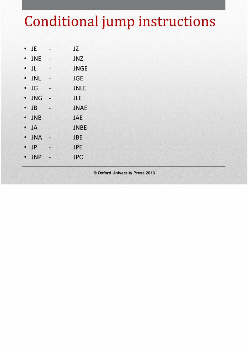
Conditional jump instructions• JE - JZ• JNE - JNZ• JL - JNGE• JNL - JGE•
JG - JNLE• JNG - JLE• JB - JNAE• JNB - JAE• JA - JNBE• JNA - JBE• JP - JPE• JNP - JPO
© Oxford University Press 2013
8/12/2019 354 33 Powerpoint-slides CH14
http://slidepdf.com/reader/full/354-33-powerpoint-slides-ch14 53/96
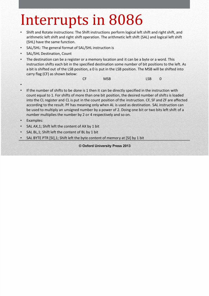
Interrupts in 8086• Shift and Rotate instructions: The Shift instructions perform logical left shift and right shift, and
arithmetic left shift and right shift operation. The arithmetic left shift (SAL) and logical left shift(SHL) have the same function.• SAL/SHL: The general format of SAL/SHL instruction is• SAL/SHL Destination, Count• The destination can be a register or a memory location and it can be a byte or a word. This
instruction shifts each bit in the specified destination some number of bit positions to the left. Asa bit is shifted out of the LSB position, a 0 is put in the LSB position. The MSB will be shifted into
carry flag (CF) as shown below: CF MSB LSB 0• • If the number of shifts to be done is 1 then it can be directly specified in the instruction with
count equal to 1. For shifts of more than one bit position, the desired number of shifts is loadedinto the CL register and CL is put in the count position of the instruction. CF, SF and ZF are affectedaccording to the result. PF has meaning only when AL is used as destination. SAL instruction can
be used to multiply an unsigned number by a power of 2. Doing one bit or two bits left shift of anumber multiplies the number by 2 or 4 respectively and so on.• Examples:• SAL AX,1; Shift left the content of AX by 1 bit• SAL BL,1; Shift left the content of BL by 1 bit• SAL BYTE PTR [SI],1; Shift left the byte content of memory at [SI] by 1 bit
© Oxford University Press 2013
8/12/2019 354 33 Powerpoint-slides CH14
http://slidepdf.com/reader/full/354-33-powerpoint-slides-ch14 54/96
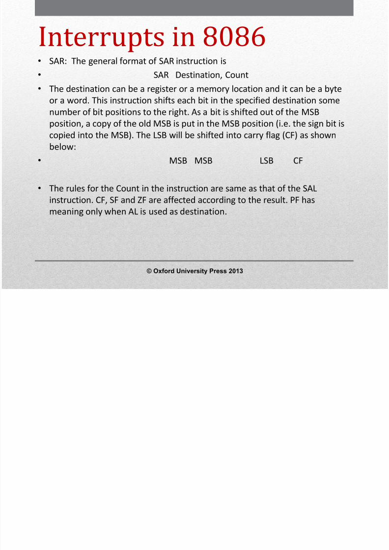
Interrupts in 8086• SAR: The general format of SAR instruction is• SAR Destination, Count• The destination can be a register or a memory location and it can be a byte
or a word. This instruction shifts each bit in the specified destination somenumber of bit positions to the right. As a bit is shifted out of the MSBposition, a copy of the old MSB is put in the MSB position (i.e. the sign bit is
copied into the MSB). The LSB will be shifted into carry flag (CF) as shownbelow:• MSB MSB LSB CF
• The rules for the Count in the instruction are same as that of the SALinstruction. CF, SF and ZF are affected according to the result. PF hasmeaning only when AL is used as destination.
© Oxford University Press 2013

8/12/2019 354 33 Powerpoint-slides CH14
http://slidepdf.com/reader/full/354-33-powerpoint-slides-ch14 55/96
Interrupts in 8086• SHR:• The general format of SHR instruction is• SHR Destination, Count• The destination can be a register or a memory location and it can be
a byte or a word. This instruction shifts each bit in the specifieddestination some number of bit positions to the right. As a bit isshifted out of the MSB position, a 0 is put in the MSB position. TheLSB will be shifted into carry flag (CF) as shown below:
• 0 MSB LSB CF
• The rules for the Count in the instruction are same as that of the SHLinstruction. CF, SF and ZF are affected according to the result. PF hasmeaning only when 8 bit destination is used.
© Oxford University Press 2013
8/12/2019 354 33 Powerpoint-slides CH14
http://slidepdf.com/reader/full/354-33-powerpoint-slides-ch14 56/96
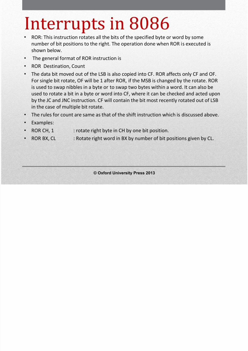
Interrupts in 8086• ROR: This instruction rotates all the bits of the specified byte or word by some
number of bit positions to the right. The operation done when ROR is executed isshown below.• The general format of ROR instruction is• ROR Destination, Count• The data bit moved out of the LSB is also copied into CF. ROR affects only CF and OF.
For single bit rotate, OF will be 1 after ROR, if the MSB is changed by the rotate. ROR
is used to swap nibbles in a byte or to swap two bytes within a word. It can also beused to rotate a bit in a byte or word into CF, where it can be checked and acted uponby the JC and JNC instruction. CF will contain the bit most recently rotated out of LSBin the case of multiple bit rotate.
• The rules for count are same as that of the shift instruction which is discussed above.• Examples:•
ROR CH, 1 : rotate right byte in CH by one bit position.• ROR BX, CL : Rotate right word in BX by number of bit positions given by CL.
© Oxford University Press 2013

8/12/2019 354 33 Powerpoint-slides CH14
http://slidepdf.com/reader/full/354-33-powerpoint-slides-ch14 57/96
Interrupts in 8086• ROL: ROL rotates all the bits in a byte or word in the
destination to the left either by 1 bit position and morethan 1 bit positions using CL as shown below:
• The data bit moved out of the MSB is also copied into CF.ROL affects only the CF and OF. OF will be 1 after a singlebit ROL if the MSB was changed by the rotate. ROL isused to swap nibbles in a byte or to swap two byteswithin a word. It can also be used to rotate a bit in a byteor word into CF, where it can be checked and acted upon
by the JC and JNC instruction. CF will contain the bit mostrecently rotated out of LSB in the case of multiple bitrotate.
© Oxford University Press 2013

8/12/2019 354 33 Powerpoint-slides CH14
http://slidepdf.com/reader/full/354-33-powerpoint-slides-ch14 58/96
Interrupts in 8086• RCR: Rotate the byte or word in the destination right
through carry flag (CF) either by one bit position or thenumber of bit positions given by the CL as shown below.
• The flag are affected by similar to ROR.• RCL: Rotate the byte or word in the destination left
through carry flag (CF) either by one bit position or thenumber of bit positions given by the CL as shown below.
• The flags are affected similar to ROL.
© Oxford University Press 2013

8/12/2019 354 33 Powerpoint-slides CH14
http://slidepdf.com/reader/full/354-33-powerpoint-slides-ch14 59/96
String Instructions• The string instructions operate on element of strings of bytes or
word.• Registers SI and DI contain the offset address within a segment of an
element (Byte or Word) in the source string and the destinationstring respectively.
• The source string is in the data segment at the offset address givenby SI and destination string is in the extra segment at the offsetaddress given by DI.
• After each string operation, SI and/or DI are automaticallyincremented or decremented by 1 or 2 (for byte or word operation)according to the D flag in the flag register. If D=0, SI and/or DI areautomatically incremented and if D=1, SI and/or DI are automaticallydecremented.
© Oxford University Press 2013

8/12/2019 354 33 Powerpoint-slides CH14
http://slidepdf.com/reader/full/354-33-powerpoint-slides-ch14 60/96
String InstructionsMNEMONICS FUNCTION
MOVSB Move string byte from DS:[SI] to ES:[DI]
MOVSW Move string word from DS:[SI] to ES:[DI]
CMPSB Compare string byte (Done by subtracting byte at ES:[DI] from the byte at DS:[SI]). Only flagsare affected and the content of bytes compared is unaffected.
CMPSW Compare string word (Done by subtracting word at ES:[DI] from the word at DS:[SI]). Onlyflags are affected and the content of words compared is unaffected.
LODSB Load string byte at DS:[SI] into AL
LODSW Load string word at DS:[SI] into AX
STOSB Store string byte in AL at ES:[DI]
STOSW Store string word in AX at ES:[DI]
SCASB Compare string byte (Done by subtracting byte at ES:[DI] from the byte at ). Only flags areaffected and the content of bytes compared is unaffected.
SCASW Compare string word (Done by subtracting word at ES:[DI] from the byte at AX). Only flagsare affected and the content of words compared is unaffected.
REP Decrement CX and Repeat the following string operation if CX ≠ 0.
REPE or REPZ Decrement CX and Repeat the following string operation if CX ≠ 0 and ZF=1.
REPNE or REPNZ Decrement CX and Repeat the following string operation if CX ≠ 0 and ZF=0.
© Oxford University Press 2013

8/12/2019 354 33 Powerpoint-slides CH14
http://slidepdf.com/reader/full/354-33-powerpoint-slides-ch14 61/96
Machine or processor control
instructions• HLT: The halt instruction stops the execution of all instructions andplaces the processor in a halt state. An interrupt or a reset signal willcause the processor to resume execution from the halt state.
• LOCK: The lock instruction asserts for the processor an exclusive
hold on the use of the system bus. It activates an external lockingsignal ( ) of the processor and it is placed as a prefix in front of theinstruction for which a lock is to be asserted. The lock will functiononly with the XCHG, ADD, OR, ADC, SBB, AND, SUB, XOR, NOT, NEG,INC and DEC instructions, when they involve a memory operand. Anundefined opcode trap interrupt will be generated if a LOCK prefix isused with any instruction not listed above.
• NOP: No operation. This instruction is used to insert delay insoftware delay programs.
© Oxford University Press 2013

8/12/2019 354 33 Powerpoint-slides CH14
http://slidepdf.com/reader/full/354-33-powerpoint-slides-ch14 62/96
Machine or processor control
instructions• ESC: This instruction is used to pass instructions to a coprocessor such as the 8087,which shares the address and data bus with an 8086. Instructions for the coprocessorare represented by a 6- bit code embedded in the escape instruction.
• As the 8086 fetches instruction bytes from memory the coprocessor also catchesthese bytes from the data bus and puts them in a queue. However the coprocessor
treats all the normal 8086 instructions as NOP instruction. When the 8086 fetches anESC instruction, the coprocessor decodes the instruction and carries out the actionspecified by the 6- bit code specified in the instruction.
• WAIT: When this instruction is executed, the 8086 checks the status of its input pinand if the input is high, it enters an idle condition in which it does not do anyprocessing. The 8086 will remain in this state until the 8086’s input pin is made lowor an interrupt signal is received on the INTR or NMI pins. If a valid interrupt occurswhile the 8086 is in this idle state, it will return to the idle state after the interruptservice routine is executed. WAIT instruction does not affect flags. It is used tosynchronize 8086 with external hardware such as 8087 coprocessor.
© Oxford University Press 2013
8/12/2019 354 33 Powerpoint-slides CH14
http://slidepdf.com/reader/full/354-33-powerpoint-slides-ch14 63/96
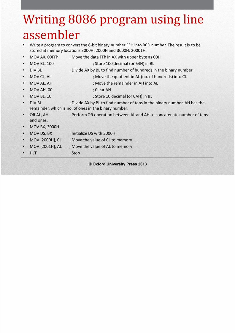
8086 Assembly LanguageProgramming•
A few assembly language programming examples similar to the assemblylanguage programming of 8085 are given in this section.
• These programs can be converted into machine language programs andexecuted in the 8086 based system either manually finding the opcode foreach instruction or by using assembler. As finding the opcode of eachinstruction of 8086 manually is time consuming, line assembler orassembler is normally used.
• The line assembler converts each mnemonics of an instruction immediatelyinto opcode as it is entered in the system and this type of assembler is usedin microprocessor trainer kits. Line assembler is stored in any one of ROMtype memory in the trainer kit.
•
The assembler needs a personal computer for generating the opcodes of anassembly language program and the generated opcodes can be downloadedto the microprocessor based system such as microprocessor trainer kit ormicroprocessor based prototype hardware through serial port or parallelport of the computer.
© Oxford University Press 2013

8/12/2019 354 33 Powerpoint-slides CH14
http://slidepdf.com/reader/full/354-33-powerpoint-slides-ch14 64/96
8086 Assembly Language
Programming• There are many assemblers like MASM (Microsoft Macro Assembler), TASM
(Turbo Assembler) and DOS Assembler which are used to convert the 8086assembly language program into machine language program.
•
While using these assemblers, the assembly language program is writtenusing assembler directives. Assembler directives are commands to theassembler to indicate the size of a variable (either byte or word), number ofbytes or words to be reserved in memory, value of a constant and name of asegment, etc. in a program.
• The assembler directives are not converted directly into opcode but theyare used to generate proper opcode of an instruction. The use of Microsoftassembler alone is discussed in the second part of this section.
© Oxford University Press 2013
8/12/2019 354 33 Powerpoint-slides CH14
http://slidepdf.com/reader/full/354-33-powerpoint-slides-ch14 65/96
8/12/2019 354 33 Powerpoint-slides CH14
http://slidepdf.com/reader/full/354-33-powerpoint-slides-ch14 66/96
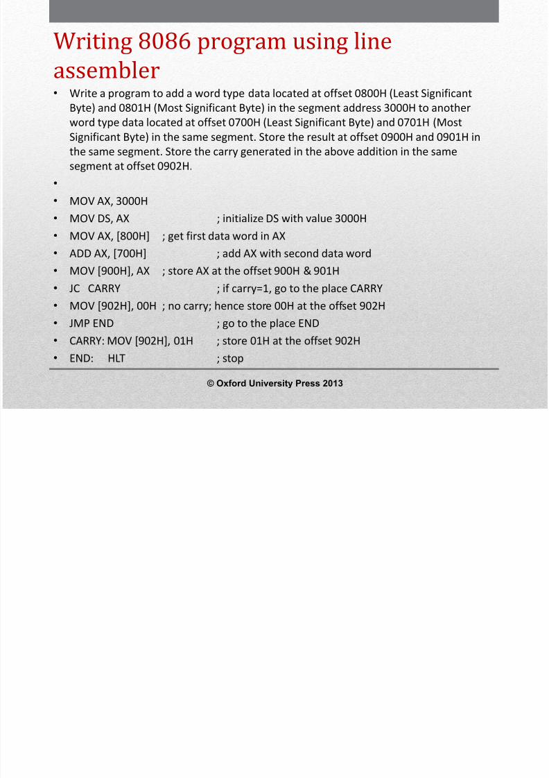
Writing 8086 program using lineassembler• Write a program to find the smallest word in an array of 100 words stored
sequentially in the memory starting from the offset 1000H in the segment address5000H and store the result at the offset 2000H in the same segment.
• MOV CX, 99 ; initialize CX with the number of comparisons (=100-1)• MOV AX, 5000H• MOV DS, AX ; initialize DS with the segment address 5000H• MOV SI, 1000H ; initialize SI with offset 1000H• MOV AX, [SI] ; get the first word in AX• START: INC SI• INC SI ; increment SI twice to point the next word• CMP AX, [SI] ; compare next word with the word in AX•
JC REPEAT ; if AX is smaller then go to REPEAT• MOV AX, [SI] ; replace the word in AX with the smaller word• REPEAT: LOOP START ; repeat the operation from START• MOV [2000H], AX ; store smallest number in AX at the offset 2000H• HLT ; stop
© Oxford University Press 2013
8/12/2019 354 33 Powerpoint-slides CH14
http://slidepdf.com/reader/full/354-33-powerpoint-slides-ch14 67/96
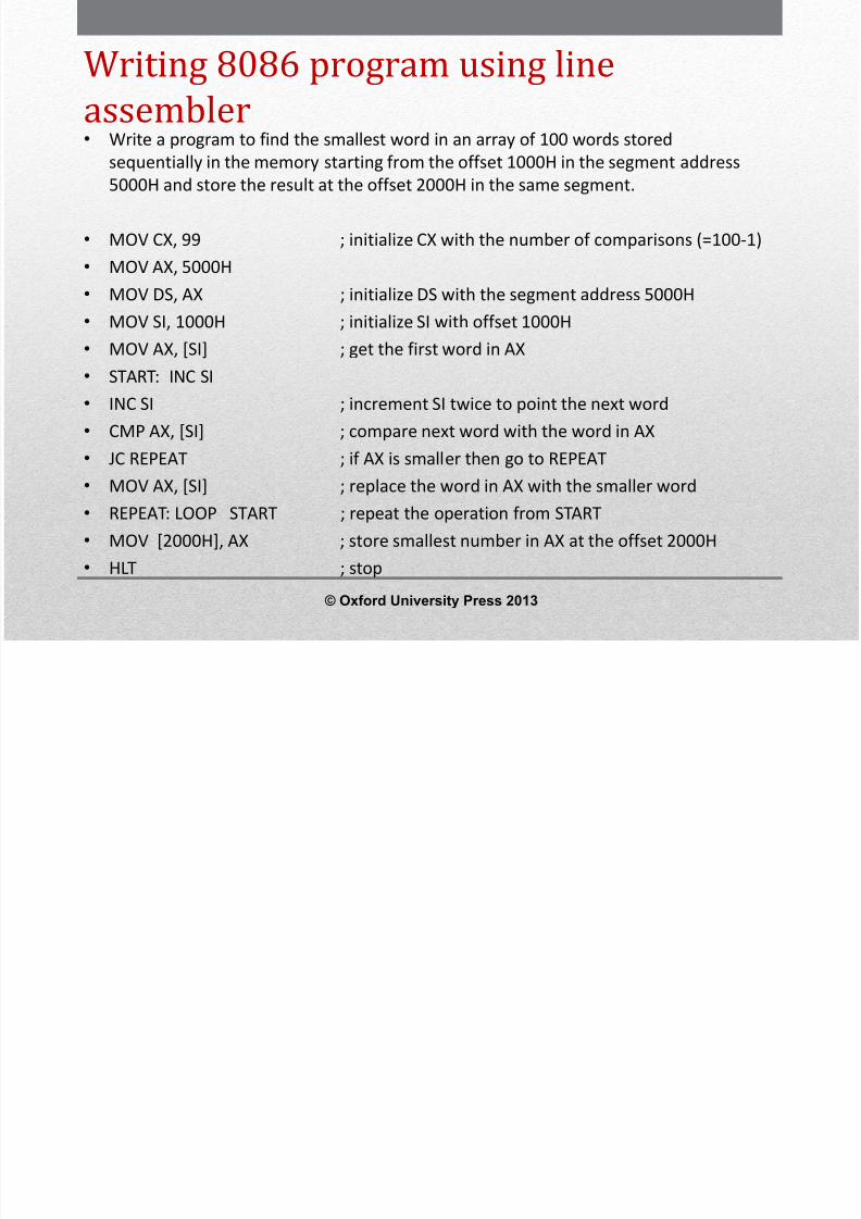
Writing 8086 program using lineassembler• Write a program to convert the 8-bit binary number FFH into BCD number. The result is to be
stored at memory locations 3000H: 2000H and 3000H: 20001H.• MOV AX, 00FFh ; Move the data FFh in AX with upper byte as 00H• MOV BL, 100 ; Store 100 decimal (or 64H) in BL• DIV BL ; Divide AX by BL to find number of hundreds in the binary number• MOV CL, AL ; Move the quotient in AL (no. of hundreds) into CL•
MOV AL, AH ; Move the remainder in AH into AL• MOV AH, 00 ; Clear AH• MOV BL, 10 ; Store 10 decimal (or 0AH) in BL• DIV BL ; Divide AX by BL to find number of tens in the binary number. AH has the
remainder, which is no. of ones in the binary number.• OR AL, AH ; Perform OR operation between AL and AH to concatenate number of tens
and ones.• MOV BX, 3000H• MOV DS, BX ; Initialize DS with 3000H• MOV [2000H], CL ; Move the value of CL to memory• MOV [2001H], AL ; Move the value of AL to memory• HLT ; Stop
© Oxford University Press 2013
8/12/2019 354 33 Powerpoint-slides CH14
http://slidepdf.com/reader/full/354-33-powerpoint-slides-ch14 68/96
8086 Assembler Directives• An assembler is a program used to convert an assembly language program
into equivalent machine language program. The assembler finds the address
of each label and substitutes the value for each of the constants andvariables in the assembly language program during the assembly process, togenerate the machine language code.
• While doing these things, the assembler may find out syntax errors and it isreported to programmer at the end of assembly process. The logical errorsor other programming errors are not found by the assembler.
• For completing all the above tasks, an assembler needs some commandsfrom the programmer namely the required storage class for a particularconstant or a variable such as byte, word or double word, logical name ofthe segments such as CODE or STACK or DATA segment, type of differentprocedures or routines such as FAR or NEAR or PUBLIC or EXTRN and end of
a segment, etc.• These types of commands are given to the assembler using some
predefined alphabetical strings called assembler directives which help theassembler to correctly generate the machine codes for the assemblylanguage program.
© Oxford University Press 2013

8/12/2019 354 33 Powerpoint-slides CH14
http://slidepdf.com/reader/full/354-33-powerpoint-slides-ch14 69/96
Assembler directives for variable andconstant definition• A) DB, DW, DD, DQ and DT: The directives DB (Define Byte), DW (Define
Word), DD (Define Double Word), DQ (Define Quad Word) and DT (DefineTen Bytes) are used to reserve one byte, one word (i.e. 2 Bytes), one doubleword (i.e. 2 words), one Quad word (i.e. 4 words) and ten bytes in memoryrespectively for storing constant, variables or string.
• Examples:•
DATA1 DB 20H ; Reserve one byte for storing DATA1 and assign the value20H to it.
• ARRAY1 DB 10H,20H,30H ;reserve three bytes for storing ARRAY1 andinitialize it with the values 10H, 20H, 30H.
• CITY DB "MADURAI” ;The ASCII code of the characters specified withindouble quotes are stored under the array or list named CITY.
• DATA2 DW 1020H ; Reserve one word for storing DATA2 and assign the value1020H to it.
• ARRAY2 DW 1030h,2000h,3000h,4000h ;Reserve 4 words for storingARRAY2 and initialize it with the specified values.
© Oxford University Press 2013

8/12/2019 354 33 Powerpoint-slides CH14
http://slidepdf.com/reader/full/354-33-powerpoint-slides-ch14 70/96
Assembler directives for variableand constant definition
• B) EQU - The directive EQU (Equivalent) is used to assigna value to a data name.
• Examples:• NUMBER EQU 50H; assign the value 50H to NUMBER• NAME EQU "RAMESH" ; assign the string “RAMESH” to
NAME
© Oxford University Press 2013
A bl di ti l t d t d (i )

8/12/2019 354 33 Powerpoint-slides CH14
http://slidepdf.com/reader/full/354-33-powerpoint-slides-ch14 71/96
Assembler directives related to code (i.e. program)location• A) ORG:•
The ORG (origin) directive directs the assembler to start the memoryallocation for a particular segment (data or code or stack) from the declaredaddress in the ORG statement. While starting the assembly process for amemory segment, the assembler initializes a location counter (LC) to keeptrack of the allotted offset addresses for the segment. When ORG directiveis not mentioned at the beginning of the segment, then LC is initialized with
the offset address 0000H. When ORG directive is mentioned at thebeginning of the segment, then LC is initialized with the offset addressspecified in the ORG directive.
• Example:• ORG 100H• When the above directive is placed at the beginning of code segment, then
the location counter is initialized with 0100H and the first instruction isstored from the offset address 0100H within the code segment. If it isplaced in data segment then the next data storage will start from the offsetaddress 0100H within the data segment.
© Oxford University Press 2013

8/12/2019 354 33 Powerpoint-slides CH14
http://slidepdf.com/reader/full/354-33-powerpoint-slides-ch14 72/96
Assembler directives related
to code (i.e. program) location• B) EVEN: The EVEN directive updates the location counter to thenext even address if the current location counter content is not aeven number.
• Example 1:• EVEN• ARRAY2 DW 20 DUP (0)• The above statements in a segment declares an array named
ARRAY2 having 20 words to start from an even address. Theadvantage of storing an array of words from an even address is thatthe 8086 takes just one memory read or write cycle to read or writethe entire word if the word is stored from an even address.Otherwise 8086 takes two memory read or write cycles to read orwrite the word.
© Oxford University Press 2013

8/12/2019 354 33 Powerpoint-slides CH14
http://slidepdf.com/reader/full/354-33-powerpoint-slides-ch14 73/96
Assembler directives related tocode (i.e. program) location• C) LENGTH:• This directive is used to determine the length of an array or string in bytes.• Example:• MOV CX, LENGTH ARRAY• CX is loaded with the number of bytes in the ARRAY.• • D) OFFSET:• This operator is used to determine the offset of a data item in a segment
containing it.• Example:• MOV BX, OFFSET TABLE• If the data item named TABLE is present in data segment then this
statement will place the offset address of TABLE in the data segment, in BXregister.
© Oxford University Press 2013
8/12/2019 354 33 Powerpoint-slides CH14
http://slidepdf.com/reader/full/354-33-powerpoint-slides-ch14 74/96
Assembler directives related tocode (i.e. program) location• E) LABEL:• The LABEL directive is used to assign a name to the current value in location
counter. The label directive is used to specify the destination of the branch-related instructions such as jump or call instructions. When the LABEL is
used to specify the destination, it is necessary to specify the label as NEARor FAR. When the destination is in the same segment, the label is specifiedas NEAR and when the destination is in another segment, it is specified asFAR.
• Example:• REPEAT LABEL NEAR• CALCULATE LABEL FAR• LABEL can also be used to specify a data item. When the LABEL is used to
specify a data item, the type of the data item must be specified. The datamay have the type as byte or word.
© Oxford University Press 2013
f
8/12/2019 354 33 Powerpoint-slides CH14
http://slidepdf.com/reader/full/354-33-powerpoint-slides-ch14 75/96
Assembler directives for segmentdeclaration• A) SEGMENT and ENDS• The SEGMENT and ENDS directives indicate the start and
end of a segment. In some cases the segment may beassigned a type such as PUBLIC (i.e. can be used by othermodules of the program while linking) or GLOBAL (can beaccessed by any other modules).
• Example:• CODE1 SEGMENT• CODE1 ENDS• The above example indicates the declaration of a code
segment named CODE 1. © Oxford University Press 2013

8/12/2019 354 33 Powerpoint-slides CH14
http://slidepdf.com/reader/full/354-33-powerpoint-slides-ch14 76/96
Assembler directives for
segment declaration• B) ASSUME: The ASSUME directive is used to inform the
assembler, the name of the logical segments to beassumed for different segments used in the program.
• Example:• ASSUME CS:CODE1, DS:DATA1• The above statement informs the assembler that the
segment address where the logical segments CODE1 andDATA1 are loaded in memory during execution, is to bestored in CS and DS registers respectively.
© Oxford University Press 2013
8/12/2019 354 33 Powerpoint-slides CH14
http://slidepdf.com/reader/full/354-33-powerpoint-slides-ch14 77/96
Assembler directives for
segment declaration• C) GROUP:• This directive is used to form logical group of segments with similar
purpose. The assembler passes information to the linker/loader to form thecode such that the group declared segments or operands must lie within a64 byte memory segment. All such segments can be addressed using thesame segment address.
• Example:• PROGRAM1 GROUP CODE1, DATA1, STACK1• The above statement directs the loader/linker to prepare an executable
(EXE) file such that CODE1, DATA1 and STACK1 segments lie within a 64 K
byte memory segment that is named as PROGRAM1. Now for the ASSUMEstatement, we can use the label PROGRAM1 rather than CODE1, DATA1 andSTACK1 as shown below:
• ASSUME CS: PROGRAM1, DS: PROGRAM1, SS: PROGRAM1
© Oxford University Press 2013

8/12/2019 354 33 Powerpoint-slides CH14
http://slidepdf.com/reader/full/354-33-powerpoint-slides-ch14 78/96
Assembler directives for
segment declaration• D) SEG:• The segment operator is used to decide the
segment address of the label, variable or procedure andsubstitutes the segment address in place of “SEG label”.
• Example:• MOV AX, SEG ARRAY1 ; Load the segment address in
which ARRAY1 is present, in AX• MOV DS, AX ; Move AX content to DS
© Oxford University Press 2013
A bl di i f

8/12/2019 354 33 Powerpoint-slides CH14
http://slidepdf.com/reader/full/354-33-powerpoint-slides-ch14 79/96
Assembler directives fordeclaring procedure• A) PROC: The PROC directive indicates the start of a named procedure. Also, the type NEAR or FAR
specify the type of the procedure.• Example:• SQUARE_ROOT PROC NEAR• The above statement indicates the beginning of a procedure named SQUARE_ROOT, which is to
be called by a program located in the same segment. The FAR directive is used for the proceduresto be called by the programs present in some other code segment other than the code segment inwhich the above procedure is present. For example SALARY PROC FAR indicates the beginning of aFAR type procedure named SALARY.
• • B) ENDP – The ENDP directive is used to indicate the end of a procedure. To mark the end of a
particular procedure, the name of the procedure may appear as a prefix with the directive ENDP.• Example:•
SALARY PROC NEAR• …….. • …….. • …….. • SALARY ENDP
© Oxford University Press 2013
Assembler directives for declaring
8/12/2019 354 33 Powerpoint-slides CH14
http://slidepdf.com/reader/full/354-33-powerpoint-slides-ch14 80/96
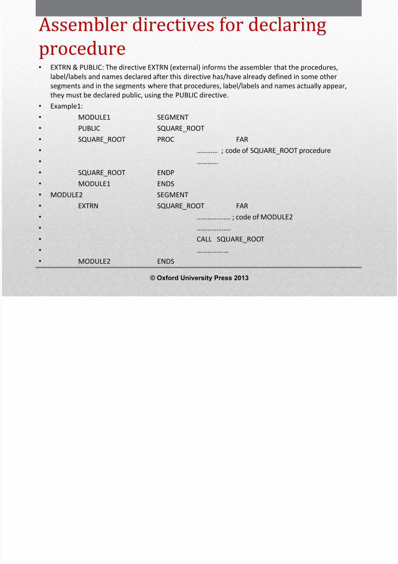
Assembler directives for declaringprocedure• EXTRN & PUBLIC: The directive EXTRN (external) informs the assembler that the procedures,
label/labels and names declared after this directive has/have already defined in some othersegments and in the segments where that procedures, label/labels and names actually appear,they must be declared public, using the PUBLIC directive.
• Example1:• MODULE1 SEGMENT• PUBLIC SQUARE_ROOT• SQUARE_ROOT PROC FAR• ………… ; code of SQUARE_ROOT procedure • ………… • SQUARE_ROOT ENDP• MODULE1 ENDS• MODULE2 SEGMENT• EXTRN SQUARE_ROOT FAR• ………………. ; code of MODULE2 • ………………. • CALL SQUARE_ROOT• ……………… • MODULE2 ENDS
© Oxford University Press 2013
O h bl di i

8/12/2019 354 33 Powerpoint-slides CH14
http://slidepdf.com/reader/full/354-33-powerpoint-slides-ch14 81/96
Other assembler directives
• PTR: The PTR (Pointer) operator is used to declare the type of a label, variable ormemory operand. The operator PTR is prefixed by either BYTE or WORD. If the prefixis BYTE then the particular label, variable or memory operand is treated as an 8-bitquantity, while if WORD prefix is used, then it is treated as a 16-bit quantity.
• Example:• INC BYTE PTR [SI]-Increments byte contents of memory location addressed by SI.• INC WORD PTR [BX]-Increments word contents of memory location addressed by BX• The PTR directive is also used to declare a label either as FAR or NEAR type. The FAR
PTR directive indicates the assembler that the label following FAR PTR is not availablewithin the same segment and the address of the label is of 32-bits (2 bytes offsetfollowed by 2 bytes segment address).
• Example:• JMP FAR PTR DIVIDE
© Oxford University Press 2013
h bl d
8/12/2019 354 33 Powerpoint-slides CH14
http://slidepdf.com/reader/full/354-33-powerpoint-slides-ch14 82/96
Other assembler directives
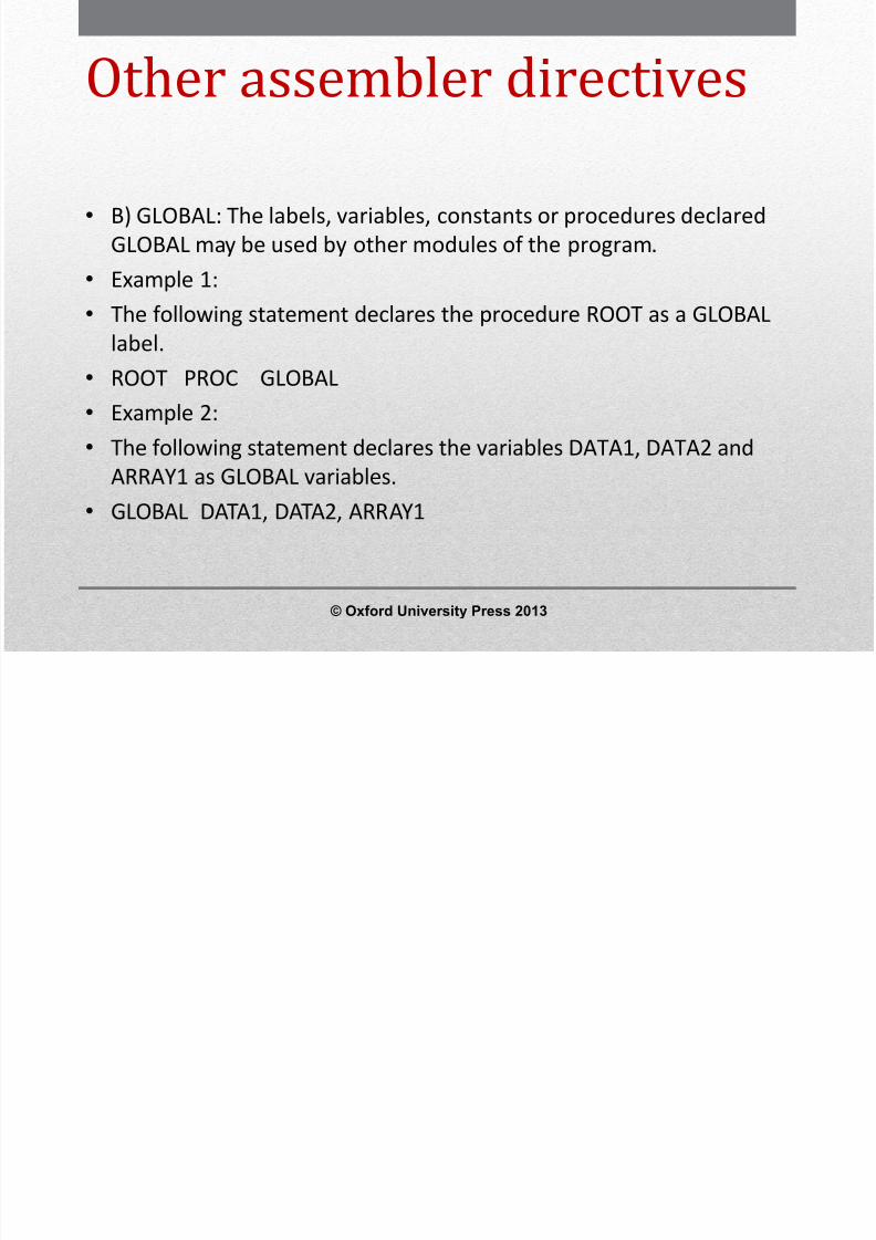
• B) GLOBAL: The labels, variables, constants or procedures declaredGLOBAL may be used by other modules of the program.
• Example 1:•
The following statement declares the procedure ROOT as a GLOBALlabel.• ROOT PROC GLOBAL• Example 2:• The following statement declares the variables DATA1, DATA2 and
ARRAY1 as GLOBAL variables.• GLOBAL DATA1, DATA2, ARRAY1
© Oxford University Press 2013
O h bl di i
8/12/2019 354 33 Powerpoint-slides CH14
http://slidepdf.com/reader/full/354-33-powerpoint-slides-ch14 83/96
Other assembler directives
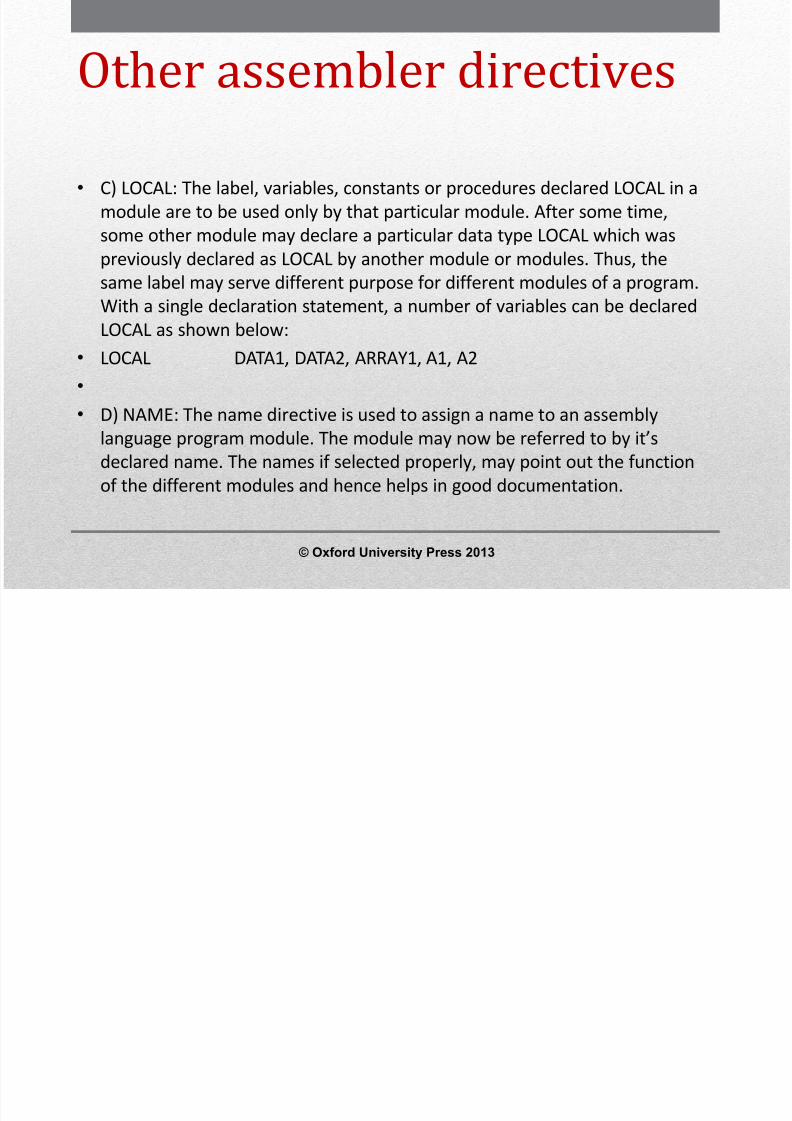
• C) LOCAL: The label, variables, constants or procedures declared LOCAL in amodule are to be used only by that particular module. After some time,some other module may declare a particular data type LOCAL which waspreviously declared as LOCAL by another module or modules. Thus, the
same label may serve different purpose for different modules of a program.With a single declaration statement, a number of variables can be declaredLOCAL as shown below:
• LOCAL DATA1, DATA2, ARRAY1, A1, A2• • D) NAME: The name directive is used to assign a name to an assembly
language program module. The module may now be referred to by it’sdeclared name. The names if selected properly, may point out the functionof the different modules and hence helps in good documentation.
© Oxford University Press 2013
O h bl di i

8/12/2019 354 33 Powerpoint-slides CH14
http://slidepdf.com/reader/full/354-33-powerpoint-slides-ch14 84/96
Other assembler directives• E) SHORT: The SHORT operator indicates to the assembler that only one byte is
required to code the displacement for a jump (i.e. displacement is within -128 to +127bytes from the address of the byte present next to the jump opcode). This method ofspecifying the jump address saves the memory. Otherwise the assembler may reserve2 bytes for the displacement in the jump instructions.
• Example:•
JMP SHORT MULTIPLY• where MULTIPLY is a label.• F) TYPE: The TYPE operator directs the assembler to decide the data type of the
specified label and replaces the ‘TYPE’ label by the decided data type. For the wordtype variable, the data type is 2, for the double word type, it is 4, and for byte type, itis 1.
•
Example:• If DATA1 is an array having word type data, then the instruction MOV BX, TYPE
DATA1 moves the value 0002H in BX.
© Oxford University Press 2013

8/12/2019 354 33 Powerpoint-slides CH14
http://slidepdf.com/reader/full/354-33-powerpoint-slides-ch14 85/96
MACRO•
Defining a MACRO:• A MACRO can be defined anywhere in a program using the
directives MACRO and ENDM. The label prior to the MACRO is themacro name which is used in the main program wherever needed.The ENDM directive marks the end of the instructions or statements
assigned with the macro name.• Example:• CALCULATE MACRO• MOV AX, [BX]• ADD AX, [BX+2]• MOV [SI], AX• ENDM
© Oxford University Press 2013
P i g t t MACRO

8/12/2019 354 33 Powerpoint-slides CH14
http://slidepdf.com/reader/full/354-33-powerpoint-slides-ch14 86/96
Passing parameters to a MACRO:• Using parameters in a macro definition, the programmer specifies the parameters of the macro those are likely to
be changed each time the macro is called. The above macro (CALCULATE) can be modified to calculate the resultfor different sets of data and store it in different memory locations as given below:
• • CALCULATE MACRO OPERAND, RESULT• MOV BX, OFFSET OPERAND• MOV AX, [BX]• ADD AX, [BX+2]•
MOV SI, OFFSET RESULT• MOV [SI], AX• ENDM• • The parameters OPERAND and RESULT can be replaced by OPERAND1, RESULT1 and OPERAND2,
RESULT2 while calling the above macro as shown below:• • ……………………….. • CALCULATE OPERAND1, RESULT1• ………………………. • ……………………… • CALCULATE OPERAND2, RESULT2• ……………………….
© Oxford University Press 2013
Writing Assembly language programs

8/12/2019 354 33 Powerpoint-slides CH14
http://slidepdf.com/reader/full/354-33-powerpoint-slides-ch14 87/96
Writing Assembly language programswhile using MASM• MASM (Microsoft Macro Assembler) is one of the assemblers commonly
used along with a LINK (linker) program to structure the machine codesgenerated by MASM in the form of an executable (EXE) file. The MASMreads the assembly language program, which is known as source programand produces an object file as output
• The LINK program accepts the object file produced by MASM along with
library files if needed, and produces an EXE file.• While writing a program for MASM, first the program listing is typed using a
text editor in the computer such as Norton’s Editor (NE), Turbo C editor, etc.After the program editing is done, it is saved under a name with anextension .ASM, for example MSI.ASM is a valid file name which can beassigned for an assembly language program.
• The programmers have to ensure that all the files namely the editor,MASM.EXE (MASM assembler) and LINK.EXE (linker) are available in thesame directory. After editing, assembling of the program has to be doneusing MASM.
© Oxford University Press 2013
8/12/2019 354 33 Powerpoint-slides CH14
http://slidepdf.com/reader/full/354-33-powerpoint-slides-ch14 88/96
Writing Assembly language
8/12/2019 354 33 Powerpoint-slides CH14
http://slidepdf.com/reader/full/354-33-powerpoint-slides-ch14 89/96
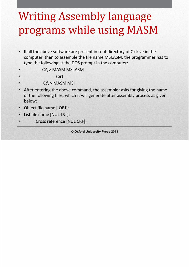
Writing Assembly languageprograms while using MASM• The programmer can type a name against every file name and then press ‘enter’ key
after giving each name. If no name is entered against each file name before pressingthe enter key in all cases then all the above three files will have the same name as thesource file.
•
The .OBJ (object) file contains the machine codes of the program which is assembled.The .LST (list) file contains the total offset map of the source file including labels,opcodes, offset addresses, memory allotment for different labels and directives.
• The cross reference (.CRF) file is used for debugging the source program as it containsthe information such as size of the file in bytes, list of labels, number of labels androutines to be called, etc. in the source program.
• After the cross reference file name is entered, the assembly process starts. If theprogram contains syntax errors, they are displayed using error code number and thecorresponding line numbers at which they appear. Once these errors are corrected bythe programmer, the assembly process will be completed successfully.
© Oxford University Press 2013
W iti g A bl l g g

8/12/2019 354 33 Powerpoint-slides CH14
http://slidepdf.com/reader/full/354-33-powerpoint-slides-ch14 90/96
Writing Assembly languageprograms while using MASM• The DOS linking program LINK.EXE is used to link the different object modules of a
source program and the function library routines to produce an integrated executablecode for the source program. The linker is invoked using the following command:
• C:\> LINK MSI.OBJ• After entering the above command, the linker asks for giving the name of the
following files:• Run file [.EXE]:• List files [NUL.MAP]:• Libraries [LIB]:• If no file names are entered for these files, then by default, the source file name is
considered with different extensions. The option input ‘Libraries’ expects any special
library name from which the functions were used by the source program. The outputof the linker program is an executable file with the entered or default file name with.EXE extension. The executable file name can be entered at the DOS prompt toexecute the file as shown below:
• C:\> MSI.EXE
© Oxford University Press 2013
W iti g A bl l g g
8/12/2019 354 33 Powerpoint-slides CH14
http://slidepdf.com/reader/full/354-33-powerpoint-slides-ch14 91/96
Writing Assembly languageprograms while using MASM• In the advanced version of MASM, both assembling and linking is combined
under a single menu invokable compile function.• The DEBUG.com is a DOS utility program that is used for debugging and
trouble –shooting 8086 assembly language programs.• The DEBUG utility enables us to have the control of the processor resources
and memory in the computer (PC) which uses one of the INTEL processor asthe CPU up to some extent as most of them run under the control ofoperating system.
• The DEBUG enables us to use the PC as a low-level 8086 microprocessor kit.By typing the DEBUG command at DOS prompt and pressing enter keyinvokes the debugging facility. A ‘ -‘(dash) appears after the successful invokeoperation of DEBUG as shown below:
• C:\> DEBUG
© Oxford University Press 2013
8/12/2019 354 33 Powerpoint-slides CH14
http://slidepdf.com/reader/full/354-33-powerpoint-slides-ch14 92/96
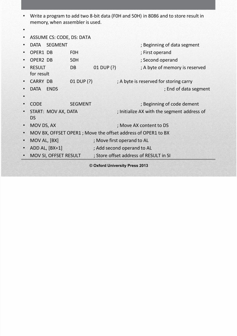
8/12/2019 354 33 Powerpoint-slides CH14
http://slidepdf.com/reader/full/354-33-powerpoint-slides-ch14 93/96
• MOV [SI], AL ; Store content of AL in the locationRESULT

8/12/2019 354 33 Powerpoint-slides CH14
http://slidepdf.com/reader/full/354-33-powerpoint-slides-ch14 94/96
RESULT• INC SI ; Increment SI to point location of carry• JC CAR ; If carry =1, go to the place CAR•
MOV [SI], 00H ; Store 00H in the location CARRY• JMP LOC1 ; go to the place LOC1• CAR: MOV [SI], 01H ; Store 01H in the location
CARRY• LOC1: MOV AH, 4CH•
INT 2IH ; Return to DOS prompt• CODE ENDS ; End of code
segment• END START ; Program ends• In the above program, the instructions MOV AH, 4CH and INT 2IH at the end
of the program are used for returning to the DOS prompt after executingthe program in the computer. If instead of these two instructions, if onewrites HLT instruction, the computer will hang after executing the programas the CPU goes to halt state and the user will not be able to examine theresult.
© Oxford University Press 2013
8/12/2019 354 33 Powerpoint-slides CH14
http://slidepdf.com/reader/full/354-33-powerpoint-slides-ch14 95/96
K t

8/12/2019 354 33 Powerpoint-slides CH14
http://slidepdf.com/reader/full/354-33-powerpoint-slides-ch14 96/96
Key terms:• Addressing mode is the way by which the microprocessor addresses the operands
while fetching data during execution of an instruction or the way by which themicroprocessor calculates the memory address, from where the next instruction tobe executed is taken, in the case of jump or call instructions.
• Instruction set of 8086 consists of Data Transfer, Arithmetic, Logical, Shift, Rotate, Flagmanipulation, Control Transfer, String and Machine Control Instructions.
• Assembler is software which is used to convert assembly language program into
machine language program.• Line assembler converts each line in assembly language program into corresponding
machine language program immediately as it is entered in the system.• Assembler directives are commands to the assembler to give various details in a
program such as the required storage class for a particular constant or a variable(byte, word or double word), logical name of the segments (CODE or STACK or DATA
segment), type of different procedures or routines (FAR or NEAR or PUBLIC orEXTRN), end of a segment (ENDS) and defining a macro (MACRO, ENDM), etc.
Related Documents