Instruction Sheet Instruction Sheet Instruction Sheet Instruction Sheet 1 1 1 M M M- - -6017 6017 6017 6017- - -35CNTRL 35CNTRL 35CNTRL 35CNTRL 2013 2013 2013 2013- - -2015 2015 2015 2015 3.5 3.5 3.5 3.5L L L EcoBoost EcoBoost EcoBoost EcoBoost Controls Pack Controls Pack Controls Pack Controls Pack NO PART OF THIS DOCUMENT MAY BE REPRODUCED WITHOUT PRIOR AGREEMENT AND WRITTEN PERMISSION OF FORD RACING PERFORMANCE PARTS Techline 1-800-367-3788 Page 1 of 22 IS-1850-0472 Factory Ford shop manuals are available from Helm Publications, 1-800-782-4356 Please visit www.fordracingparts.com for the most current instruction and warranty information. Please visit www.fordracingparts.com for the most current instruction and warranty information. Please visit www.fordracingparts.com for the most current instruction and warranty information. Please visit www.fordracingparts.com for the most current instruction and warranty information. PLEASE READ ALL OF THE FOLLOWING INSTRUCTIONS CAREFULLY PRIOR TO INSTALLATION. PLEASE READ ALL OF THE FOLLOWING INSTRUCTIONS CAREFULLY PRIOR TO INSTALLATION. PLEASE READ ALL OF THE FOLLOWING INSTRUCTIONS CAREFULLY PRIOR TO INSTALLATION. PLEASE READ ALL OF THE FOLLOWING INSTRUCTIONS CAREFULLY PRIOR TO INSTALLATION. AT AT AT AT ANY TIME YOU DO NOT UNDERSTAND THE INSTRUCTIONS, PLEASE CALL TH ANY TIME YOU DO NOT UNDERSTAND THE INSTRUCTIONS, PLEASE CALL TH ANY TIME YOU DO NOT UNDERSTAND THE INSTRUCTIONS, PLEASE CALL TH ANY TIME YOU DO NOT UNDERSTAND THE INSTRUCTIONS, PLEASE CALL THE E E E FORD PERFORMANCE FORD PERFORMANCE FORD PERFORMANCE FORD PERFORMANCE TECHLINE AT 1 TECHLINE AT 1 TECHLINE AT 1 TECHLINE AT 1-800 800 800 800-367 367 367 367-3788 3788 3788 3788 3.5 3.5 3.5 3.5L L L L EcoB EcoB EcoB EcoBoost oost oost oost Co Co Co Controls Pack Installation Manual ntrols Pack Installation Manual ntrols Pack Installation Manual ntrols Pack Installation Manual

Welcome message from author
This document is posted to help you gain knowledge. Please leave a comment to let me know what you think about it! Share it to your friends and learn new things together.
Transcript
Instruction SheetInstruction SheetInstruction SheetInstruction Sheet
1111 MMMM----6017601760176017----35CNTRL35CNTRL35CNTRL35CNTRL 2013201320132013----2015 2015 2015 2015 3.53.53.53.5LLLL EcoBoost EcoBoost EcoBoost EcoBoost Controls PackControls PackControls PackControls Pack
NO PART OF THIS DOCUMENT MAY BE REPRODUCED WITHOUT PRIOR AGREEMENT AND WRITTEN PERMISSION OF FORD RACING PERFORMANCE PARTS
Techline 1-800-367-3788 Page 1 of 22 IS-1850-0472
Factory Ford shop manuals are available from Helm Publications, 1-800-782-4356
Please visit www.fordracingparts.com for the most current instruction and warranty information.Please visit www.fordracingparts.com for the most current instruction and warranty information.Please visit www.fordracingparts.com for the most current instruction and warranty information.Please visit www.fordracingparts.com for the most current instruction and warranty information.
PLEASE READ ALL OF THE FOLLOWING INSTRUCTIONS CAREFULLY PRIOR TO INSTALLATION.PLEASE READ ALL OF THE FOLLOWING INSTRUCTIONS CAREFULLY PRIOR TO INSTALLATION.PLEASE READ ALL OF THE FOLLOWING INSTRUCTIONS CAREFULLY PRIOR TO INSTALLATION.PLEASE READ ALL OF THE FOLLOWING INSTRUCTIONS CAREFULLY PRIOR TO INSTALLATION. AT AT AT AT ANY TIME YOU DO NOT UNDERSTAND THE INSTRUCTIONS, PLEASE CALL THANY TIME YOU DO NOT UNDERSTAND THE INSTRUCTIONS, PLEASE CALL THANY TIME YOU DO NOT UNDERSTAND THE INSTRUCTIONS, PLEASE CALL THANY TIME YOU DO NOT UNDERSTAND THE INSTRUCTIONS, PLEASE CALL THE E E E FORD PERFORMANCEFORD PERFORMANCEFORD PERFORMANCEFORD PERFORMANCE
TECHLINE AT 1TECHLINE AT 1TECHLINE AT 1TECHLINE AT 1----800800800800----367367367367----3788378837883788
3.53.53.53.5L L L L EcoBEcoBEcoBEcoBoost oost oost oost CoCoCoControls Pack Installation Manualntrols Pack Installation Manualntrols Pack Installation Manualntrols Pack Installation Manual
Instruction SheetInstruction SheetInstruction SheetInstruction Sheet
1111 MMMM----6017601760176017----35CNTRL35CNTRL35CNTRL35CNTRL 2013201320132013----2015 2015 2015 2015 3.53.53.53.5LLLL EcoBoost EcoBoost EcoBoost EcoBoost Controls PackControls PackControls PackControls Pack
NO PART OF THIS DOCUMENT MAY BE REPRODUCED WITHOUT PRIOR AGREEMENT AND WRITTEN PERMISSION OF FORD RACING PERFORMANCE PARTS
Techline 1-800-367-3788 Page 2 of 22 IS-1850-0472
Factory Ford shop manuals are available from Helm Publications, 1-800-782-4356
TABLE OF CONTENTSTABLE OF CONTENTSTABLE OF CONTENTSTABLE OF CONTENTS
SectionSectionSectionSection TopicTopicTopicTopic PagePagePagePage
1.01.01.01.0 Introduction .…………………………………………………………………………………………………………………….. 2222
2.02.02.02.0 Overview .………………………………………………………………………………………………………………………….. 2222
3.03.03.03.0 Included Components ..……………………………………………………………….……………………………………. 2222----7777
4.04.04.04.0 Pre-Installation of Harness and Parts …………………………………………………………………………….. 7777----11111111
5.05.05.05.0 Controls Pack Harness Installation Instructions ……..……………………………...……………………… 11111111----11114444
6.06.06.06.0 16-way I/P Pigtail Connection Details ………………...………………………………………………………….. 14141414----16161616
7777.0.0.0.0 Fuel System …………………………………..…………………………………………………..……………………………… 17171717----11118888
8888.0.0.0.0 Initial Start-Up .………………………………………………………………………………………………………………… 18181818
9999.0.0.0.0 Wire Usage Schematics ….………………………………………………………………………………………………… 18181818----20202020
10101010.0.0.0.0 Fuses & Relays ..…..…………………………………………………………………………...……………………………… 21212121
11111111.0.0.0.0 Connector Faces …………………………………..…………………………………………………………………………… 21212121----22222222
1.01.01.01.0 IIIIntroductionntroductionntroductionntroduction
This kit was developed by Ford Performance in order to allow performance enthusiasts the ability to install the 3.5L EcoBoost Crate
Engine (Ford Performance P/N: M-6007-35T) into the application of their choice. The system supports use of a manual
transmission only.
Note: Cruise control is not available with this system.
2.0 2.0 2.0 2.0 OOOOverviewverviewverviewverview
This booklet provides a step by step guide for the preparation and installation of the controls pack. Please read the instructions
thoroughly before starting the installation. If you have any questions, contact Ford Performance Technical Support at (800) 367-
3788.
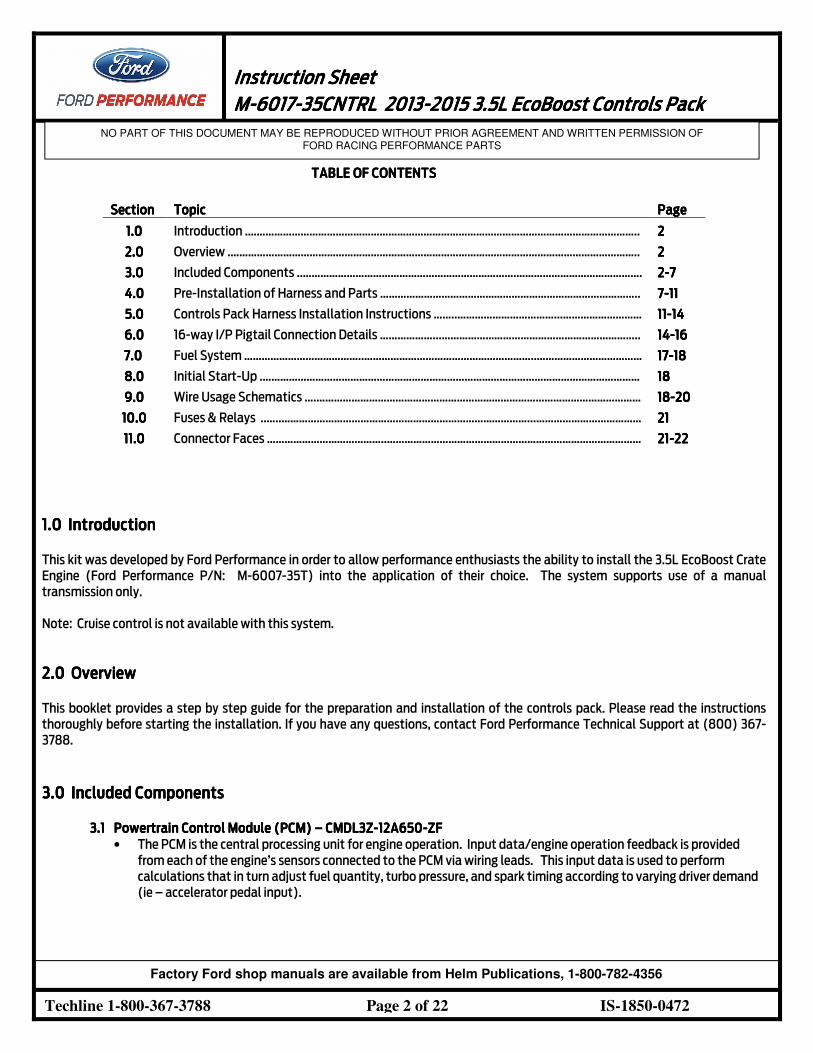
3.0 3.0 3.0 3.0 Included ComponentsIncluded ComponentsIncluded ComponentsIncluded Components
3.13.13.13.1 Powertrain Control Module (PCM)Powertrain Control Module (PCM)Powertrain Control Module (PCM)Powertrain Control Module (PCM) –––– CMDL3ZCMDL3ZCMDL3ZCMDL3Z----12A65012A65012A65012A650----ZFZFZFZF
• The PCM is the central processing unit for engine operation. Input data/engine operation feedback is provided
from each of the engine’s sensors connected to the PCM via wiring leads. This input data is used to perform
calculations that in turn adjust fuel quantity, turbo pressure, and spark timing according to varying driver demand
(ie – accelerator pedal input).
Instruction SheetInstruction SheetInstruction SheetInstruction Sheet
1111 MMMM----6017601760176017----35CNTRL35CNTRL35CNTRL35CNTRL 2013201320132013----2015 2015 2015 2015 3.53.53.53.5LLLL EcoBoost EcoBoost EcoBoost EcoBoost Controls PackControls PackControls PackControls Pack
NO PART OF THIS DOCUMENT MAY BE REPRODUCED WITHOUT PRIOR AGREEMENT AND WRITTEN PERMISSION OF FORD RACING PERFORMANCE PARTS
Techline 1-800-367-3788 Page 3 of 22 IS-1850-0472
Factory Ford shop manuals are available from Helm Publications, 1-800-782-4356
• The wiring that plugs into the PCM is integral to the wiring harness that was included with your 3.5L crate engine,
the length of these wiring leads dictate that mounting location be in close proximity to the engine itself.
• The PCM in this Controls Pack has a custom software and calibration dataset which were specifically
modified/developed by Ford Performance engineers to provide peak performance and reliability with the 3.5L
EcoBoost Crate Engine (Ford Performance P/N: M-6007-35T)
PCM Calibration Application Notes:
• The calibration provided in this PCM will NOT work with the ‘Returnless’ fuel system as used on factory vehicles.
Use of a return style fuel system is required. Refer to Section 7 of this manual for more information on fuel system
requirements for this PCM.
• The Air Filter Assembly with Integral Mass Air Flow Sensor included with this kit must be used to achieve
acceptable engine performance. If air filter assembly provided is not used, calibration may be required. Refer to
Section 3.7 for more information about Air Inlet System requirements.
• Premium Fuel Only (91 Octane or higher).Premium Fuel Only (91 Octane or higher).Premium Fuel Only (91 Octane or higher).Premium Fuel Only (91 Octane or higher).
NOTE: Due to the fuel system requirement described above, installation of thNOTE: Due to the fuel system requirement described above, installation of thNOTE: Due to the fuel system requirement described above, installation of thNOTE: Due to the fuel system requirement described above, installation of this PCM in ANY Productionis PCM in ANY Productionis PCM in ANY Productionis PCM in ANY Production vehicle will result in a vehicle will result in a vehicle will result in a vehicle will result in a
nononono----start condition!start condition!start condition!start condition!
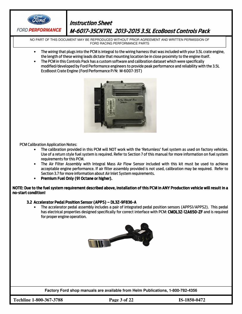
3.2 3.2 3.2 3.2 Accelerator PedalAccelerator PedalAccelerator PedalAccelerator Pedal Position Sensor (APPS) Position Sensor (APPS) Position Sensor (APPS) Position Sensor (APPS) –––– DL3ZDL3ZDL3ZDL3Z----9F8369F8369F8369F836----AAAA
• The accelerator pedal assembly includes a pair of integrated pedal position sensors (APPS1/APPS2). This pedal
has electrical properties designed specifically for correct interface with PCM: CMDL3ZCMDL3ZCMDL3ZCMDL3Z----12A65012A65012A65012A650----ZFZFZFZF and is required
for proper engine operation.
Instruction SheetInstruction SheetInstruction SheetInstruction Sheet
1111 MMMM----6017601760176017----35CNTRL35CNTRL35CNTRL35CNTRL 2013201320132013----2015 2015 2015 2015 3.53.53.53.5LLLL EcoBoost EcoBoost EcoBoost EcoBoost Controls PackControls PackControls PackControls Pack
NO PART OF THIS DOCUMENT MAY BE REPRODUCED WITHOUT PRIOR AGREEMENT AND WRITTEN PERMISSION OF FORD RACING PERFORMANCE PARTS
Techline 1-800-367-3788 Page 4 of 22 IS-1850-0472
Factory Ford shop manuals are available from Helm Publications, 1-800-782-4356
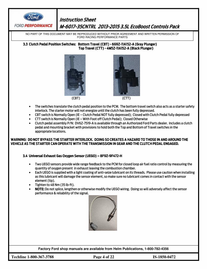
3.3 3.3 3.3 3.3 Clutch Pedal Position SwitchesClutch Pedal Position SwitchesClutch Pedal Position SwitchesClutch Pedal Position Switches: : : : BottomBottomBottomBottom TravelTravelTravelTravel (CBT)(CBT)(CBT)(CBT) ---- 6G9Z6G9Z6G9Z6G9Z----11A15211A15211A15211A152----A A A A (Gray Plunger)(Gray Plunger)(Gray Plunger)(Gray Plunger)
TopTopTopTop TravelTravelTravelTravel (CTT)(CTT)(CTT)(CTT) ---- 4M5Z4M5Z4M5Z4M5Z----11A15211A15211A15211A152----A A A A (Black Plunger)(Black Plunger)(Black Plunger)(Black Plunger)
(CBT) (CTT)
• The switches translate the clutch pedal position to the PCM. The bottom travel switch also acts as a starter safety
interlock. The starter motor will not energize until the clutch has been fully depressed.
• CBT switch is Normally Open (IE – Clutch Pedal NOT fully depressed); Closed with Clutch Pedal fully depressed
• CTT switch is Normally Open (IE – With Foot off Clutch Pedal); Closed Otherwise
• Clutch pedal assembly P/N: DV6Z-7519-A is available through an Authorized Ford Parts dealer. Includes a clutch
pedal and mounting bracket with provisions to hold both the Top and Bottom of Travel switches in the
appropriate locations.
WARNING: DO NOT BYPASS THE STARTER WARNING: DO NOT BYPASS THE STARTER WARNING: DO NOT BYPASS THE STARTER WARNING: DO NOT BYPASS THE STARTER INTERLOCK. DOINGINTERLOCK. DOINGINTERLOCK. DOINGINTERLOCK. DOING SOSOSOSO CREATES A HAZARD TO THOSE IN AND AROUND THE CREATES A HAZARD TO THOSE IN AND AROUND THE CREATES A HAZARD TO THOSE IN AND AROUND THE CREATES A HAZARD TO THOSE IN AND AROUND THE
VEHICLE AS THE STARTER CAN VEHICLE AS THE STARTER CAN VEHICLE AS THE STARTER CAN VEHICLE AS THE STARTER CAN OPERATEOPERATEOPERATEOPERATE WITH THE WITH THE WITH THE WITH THE TRANSMISSIONTRANSMISSIONTRANSMISSIONTRANSMISSION IN GEAR AND THE CLUTCH IN GEAR AND THE CLUTCH IN GEAR AND THE CLUTCH IN GEAR AND THE CLUTCH PEDAL PEDAL PEDAL PEDAL ENGAGEDENGAGEDENGAGEDENGAGED. . . .
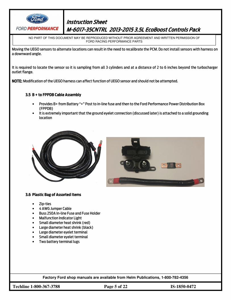
3.43.43.43.4 Universal Exhaust Gas Oxygen Sensor (UEGO)Universal Exhaust Gas Oxygen Sensor (UEGO)Universal Exhaust Gas Oxygen Sensor (UEGO)Universal Exhaust Gas Oxygen Sensor (UEGO) –––– 8F9Z8F9Z8F9Z8F9Z----9F4729F4729F4729F472----HHHH
• Two UEGO sensors provide wide range feedback to the PCM for closed loop air fuel ratio control by measuring the
quantity of oxygen present in exhaust leaving the combustion chamber.
• Each UEGO is supplied with a light coating of anti-seize lubricant on its threads. Please use caution when installing
as this lubricant will damage the sensor element, so make sure no lubricant comes in contact with the sensor
element (tip).
• Tighten to 48 Nm (35 lb-ft).
• NOTE:NOTE:NOTE:NOTE: Do not splice, lengthen or otherwise modify the UEGO wiring. Doing so will adversely affect the sensor
performance & reliability of the signal.
Instruction SheetInstruction SheetInstruction SheetInstruction Sheet
1111 MMMM----6017601760176017----35CNTRL35CNTRL35CNTRL35CNTRL 2013201320132013----2015 2015 2015 2015 3.53.53.53.5LLLL EcoBoost EcoBoost EcoBoost EcoBoost Controls PackControls PackControls PackControls Pack
NO PART OF THIS DOCUMENT MAY BE REPRODUCED WITHOUT PRIOR AGREEMENT AND WRITTEN PERMISSION OF FORD RACING PERFORMANCE PARTS
Techline 1-800-367-3788 Page 5 of 22 IS-1850-0472
Factory Ford shop manuals are available from Helm Publications, 1-800-782-4356
Moving the UEGO sensors to alternate locations can result in the need to recalibrate the PCM. Do not install sensors with harness on
a downward angle.
It is required to locate the sensor so it is sampling from all 3 cylinders and at a distance of 2 to 6 inches beyond the turbocharger
outlet flange.
NOTE: NOTE: NOTE: NOTE: Modification of the UEGO harness can affect function of UEGO sensor and should not be attempted.
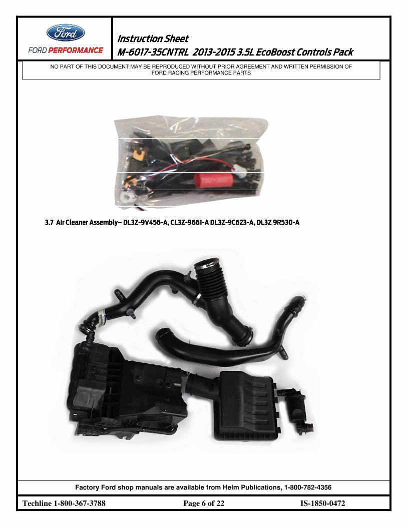
3.53.53.53.5 B + to B + to B + to B + to FPPDBFPPDBFPPDBFPPDB Cable AssembCable AssembCable AssembCable Assemblylylyly
• Provides B+ from Battery “+” Post to in-line fuse and then to the Ford Performance Power Distribution Box
(FPPDB)
• It is extremely important that the ground eyelet connection (discussed later) is attached to a solid grounding
location
3.63.63.63.6 Plastic Bag of Assorted ItemsPlastic Bag of Assorted ItemsPlastic Bag of Assorted ItemsPlastic Bag of Assorted Items
• Zip-ties
• 4 AWG Jumper Cable
• Buss 250A In-line Fuse and Fuse Holder
• Malfunction Indicator Light
• Small diameter heat shrink (red)
• Large diameter heat shrink (black)
• Large diameter eyelet terminal
• Small diameter eyelet terminal
• Two battery terminal lugs
Instruction SheetInstruction SheetInstruction SheetInstruction Sheet
1111 MMMM----6017601760176017----35CNTRL35CNTRL35CNTRL35CNTRL 2013201320132013----2015 2015 2015 2015 3.53.53.53.5LLLL EcoBoost EcoBoost EcoBoost EcoBoost Controls PackControls PackControls PackControls Pack
NO PART OF THIS DOCUMENT MAY BE REPRODUCED WITHOUT PRIOR AGREEMENT AND WRITTEN PERMISSION OF FORD RACING PERFORMANCE PARTS
Techline 1-800-367-3788 Page 6 of 22 IS-1850-0472
Factory Ford shop manuals are available from Helm Publications, 1-800-782-4356
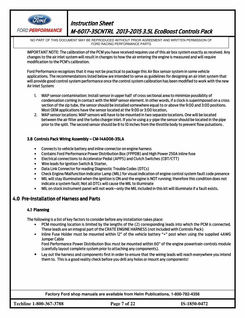
3.73.73.73.7 Air Cleaner AssemblyAir Cleaner AssemblyAir Cleaner AssemblyAir Cleaner Assembly–––– DL3ZDL3ZDL3ZDL3Z----9V4569V4569V4569V456----A, CL3ZA, CL3ZA, CL3ZA, CL3Z----9661966196619661----A DL3ZA DL3ZA DL3ZA DL3Z----9C6239C6239C6239C623----A, DL3Z 9R530A, DL3Z 9R530A, DL3Z 9R530A, DL3Z 9R530----AAAA
Instruction SheetInstruction SheetInstruction SheetInstruction Sheet
1111 MMMM----6017601760176017----35CNTRL35CNTRL35CNTRL35CNTRL 2013201320132013----2015 2015 2015 2015 3.53.53.53.5LLLL EcoBoost EcoBoost EcoBoost EcoBoost Controls PackControls PackControls PackControls Pack
NO PART OF THIS DOCUMENT MAY BE REPRODUCED WITHOUT PRIOR AGREEMENT AND WRITTEN PERMISSION OF FORD RACING PERFORMANCE PARTS
Techline 1-800-367-3788 Page 7 of 22 IS-1850-0472
Factory Ford shop manuals are available from Helm Publications, 1-800-782-4356
IMPORTANT NOTE: The calibration of the PCM you have received requires use of this air box system exactly as received. Any
changes to the air inlet system will result in changes to how the air entering the engine is measured and will require
modification to the PCM's calibration.
Ford Performance recognizes that it may not be practical to package this Air Box sensor system in some vehicle
applications. The recommendations listed below are intended to serve as guidelines for designing an air inlet system that
will provide good control system performance once the control system calibration has been modified to work with the new
Air Inlet System:
1. MAP sensor contamination: Install sensor in upper half of cross sectional area to minimize possibility of
condensation coming in contact with the MAP sensor element. In other words, if a clock is superimposed on a cross
section of the zip tube, the sensor should be installed somewhere equal to or above the 9:00 and 3:00 positions.
Most OEM applications have the sensor located at the 9:00 or 3:00 location,
2. MAP sensor locations: MAP sensors will have to be mounted in two separate locations. One will be located
between the air filter and the turbo charger inlet. If you’re using a y-pipe the sensor should be located in the pipe
prior to the split. The second sensor should be 8 to 10 inches from the throttle body to prevent flow pulsations .
3.3.3.3.8888 Controls Pack Wiring AssemblyControls Pack Wiring AssemblyControls Pack Wiring AssemblyControls Pack Wiring Assembly –––– CMCMCMCM----14A00614A00614A00614A006----35LA35LA35LA35LA
• Connects to vehicle battery and inline connector on engine harness
• Contains Ford Performance Power Distribution Box (FPPDB) and High Power 250A inline fuse
• Electrical connections to Accelerator Pedal (APPS) and Clutch Switches (CBT/CTT)
• Wire leads for Ignition Switch & Starter,
• Data Link Connector for reading Diagnostic Trouble Codes (DTCs)
• Check Engine/Malfunction Indicator Lamp (MIL) for visual indication of engine control system fault code presence
• MIL will stay illuminated when the ignition is ON and the engine is NOT running; therefore this condition does not
indicate a system fault; Not all DTCs will cause the MIL to illuminate
• MIL on stock instrument panel will not work—only the MIL included in this kit will illuminate if a fault exists.
4.0 4.0 4.0 4.0 PrePrePrePre----Installation of Harness and PartsInstallation of Harness and PartsInstallation of Harness and PartsInstallation of Harness and Parts
4.1 4.1 4.1 4.1 PlanningPlanningPlanningPlanning
The following is a list of key factors to consider before any installation takes place:
• PCM mounting location is limited by the lengths of the (2) corresponding leads into which the PCM is connected.
These leads are an integral part of the CRATE ENGINE HARNESS (not included with Controls Pack)
• Inline Fuse Holder must be mounted within 12” of the vehicle battery “+” post when using the supplied 4AWG
Jumper Cable
Ford Performance Power Distribution Box must be mounted within 60” of the engine powertrain controls module
(carefully layout complete system prior to attaching any components).
• Lay out the harness and components first in order to ensure that the wiring leads will reach everywhere you intend
them to. This is a good reality check before you drill any holes or mount any components!
Instruction SheetInstruction SheetInstruction SheetInstruction Sheet
1111 MMMM----6017601760176017----35CNTRL35CNTRL35CNTRL35CNTRL 2013201320132013----2015 2015 2015 2015 3.53.53.53.5LLLL EcoBoost EcoBoost EcoBoost EcoBoost Controls PackControls PackControls PackControls Pack
NO PART OF THIS DOCUMENT MAY BE REPRODUCED WITHOUT PRIOR AGREEMENT AND WRITTEN PERMISSION OF FORD RACING PERFORMANCE PARTS
Techline 1-800-367-3788 Page 8 of 22 IS-1850-0472
Factory Ford shop manuals are available from Helm Publications, 1-800-782-4356
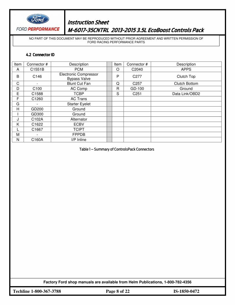
4.2 4.2 4.2 4.2 Connector IDConnector IDConnector IDConnector ID
Item Connector # Description Item Connector # Description
A C1551B PCM O C2040 APPS
B C146 Electronic Compressor
Bypass Valve P C277 Clutch Top
C - Blunt Cut Fan Q C257 Clutch Bottom
D C100 AC Comp R GD-100 Ground
E C1588 TCBP S C251 Data Link/OBD2
F C1260 AC Trans
G - Starter Eyelet
H GD200 Ground
I GD300 Ground
J C102A Alternator
K C1622 ECBV
L C1667 TCIPT
M - FPPDB
N C160A I/P Inline
Table 1 – Summary of ControlsPack Connectors
Instruction SheetInstruction SheetInstruction SheetInstruction Sheet
1111 MMMM----6017601760176017----35CNTRL35CNTRL35CNTRL35CNTRL 2013201320132013----2015 2015 2015 2015 3.53.53.53.5LLLL EcoBoost EcoBoost EcoBoost EcoBoost Controls PackControls PackControls PackControls Pack
NO PART OF THIS DOCUMENT MAY BE REPRODUCED WITHOUT PRIOR AGREEMENT AND WRITTEN PERMISSION OF FORD RACING PERFORMANCE PARTS
Techline 1-800-367-3788 Page 9 of 22 IS-1850-0472
Factory Ford shop manuals are available from Helm Publications, 1-800-782-4356
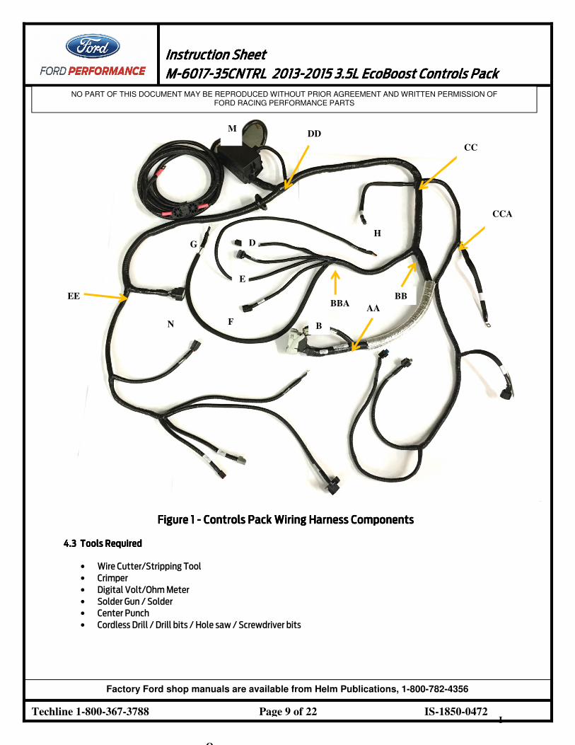
Figure 1Figure 1Figure 1Figure 1 ---- Controls Pack Wiring Harness ComponentsControls Pack Wiring Harness ComponentsControls Pack Wiring Harness ComponentsControls Pack Wiring Harness Components
4.34.34.34.3 Tools RequiredTools RequiredTools RequiredTools Required
• Wire Cutter/Stripping Tool
• Crimper
• Digital Volt/Ohm Meter
• Solder Gun / Solder
• Center Punch
• Cordless Drill / Drill bits / Hole saw / Screwdriver bits
I
CCA
CC
AA
A
B
H
DD
M
BB BBA
D
E
F
G
N
EE
O
Instruction SheetInstruction SheetInstruction SheetInstruction Sheet
1111 MMMM----6017601760176017----35CNTRL35CNTRL35CNTRL35CNTRL 2013201320132013----2015 2015 2015 2015 3.53.53.53.5LLLL EcoBoost EcoBoost EcoBoost EcoBoost Controls PackControls PackControls PackControls Pack
NO PART OF THIS DOCUMENT MAY BE REPRODUCED WITHOUT PRIOR AGREEMENT AND WRITTEN PERMISSION OF FORD RACING PERFORMANCE PARTS
Techline 1-800-367-3788 Page 10 of 22 IS-1850-0472
Factory Ford shop manuals are available from Helm Publications, 1-800-782-4356
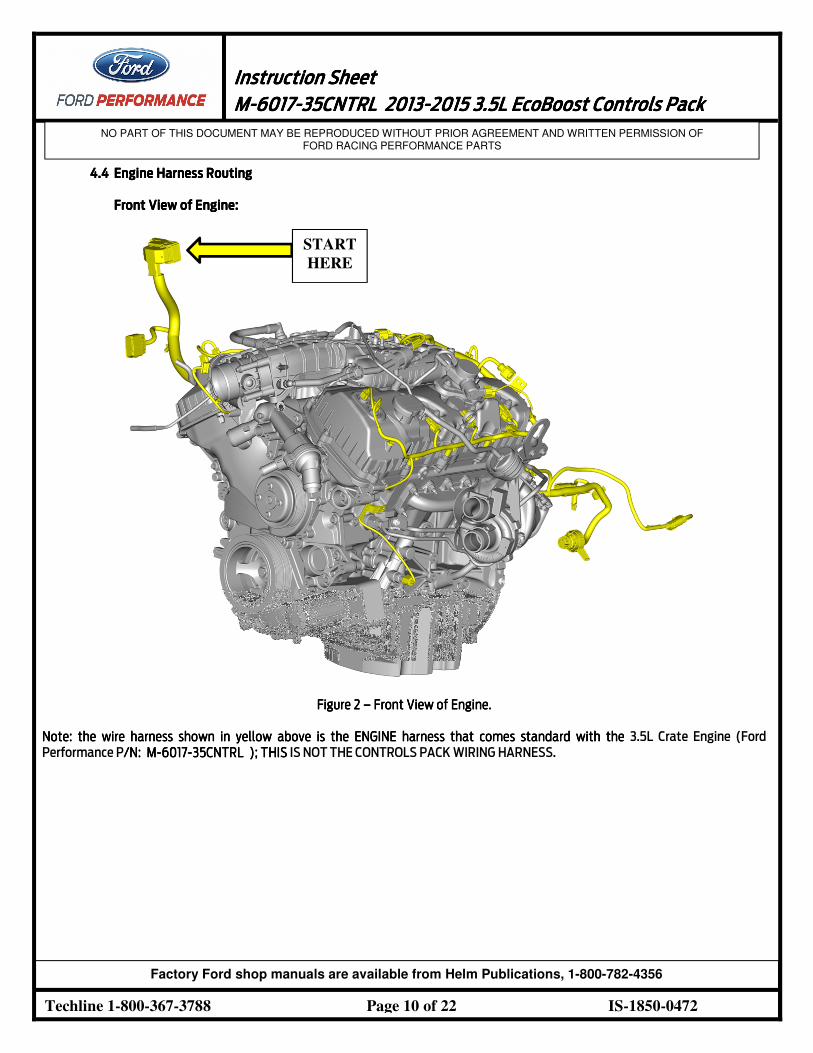
4.44.44.44.4 Engine Harness RoutingEngine Harness RoutingEngine Harness RoutingEngine Harness Routing
FrontFrontFrontFront View of Engine:View of Engine:View of Engine:View of Engine:
Figure Figure Figure Figure 2222 –––– FrontFrontFrontFront View of EngineView of EngineView of EngineView of Engine....
NoteNoteNoteNote: the wire harness shown in yellow: the wire harness shown in yellow: the wire harness shown in yellow: the wire harness shown in yellow above is the ENGINE harness that comes standard with the above is the ENGINE harness that comes standard with the above is the ENGINE harness that comes standard with the above is the ENGINE harness that comes standard with the 3.5L Crate Engine (Ford
Performance P/N: /N: /N: /N: MMMM----6017601760176017----35CNTRL 35CNTRL 35CNTRL 35CNTRL ); THIS); THIS); THIS); THIS IS NOT THE CONTROLS PACK WIRING HARNESS.
START
HERE
Instruction SheetInstruction SheetInstruction SheetInstruction Sheet
1111 MMMM----6017601760176017----35CNTRL35CNTRL35CNTRL35CNTRL 2013201320132013----2015 2015 2015 2015 3.53.53.53.5LLLL EcoBoost EcoBoost EcoBoost EcoBoost Controls PackControls PackControls PackControls Pack
NO PART OF THIS DOCUMENT MAY BE REPRODUCED WITHOUT PRIOR AGREEMENT AND WRITTEN PERMISSION OF FORD RACING PERFORMANCE PARTS
Techline 1-800-367-3788 Page 11 of 22 IS-1850-0472
Factory Ford shop manuals are available from Helm Publications, 1-800-782-4356
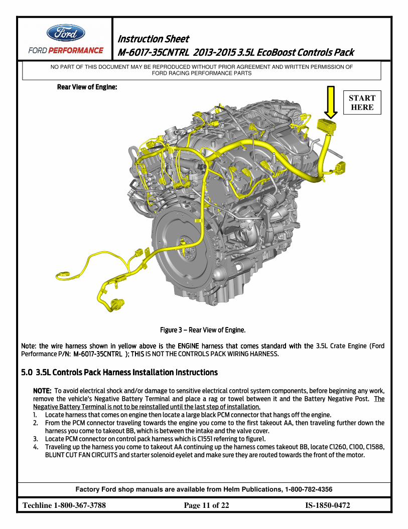
RearRearRearRear View of Engine:View of Engine:View of Engine:View of Engine:
Figure Figure Figure Figure 3333 –––– RearRearRearRear View of EngineView of EngineView of EngineView of Engine....
Note: the wire harness shown in yellow above is the ENGINE harness that comes standard with the Note: the wire harness shown in yellow above is the ENGINE harness that comes standard with the Note: the wire harness shown in yellow above is the ENGINE harness that comes standard with the Note: the wire harness shown in yellow above is the ENGINE harness that comes standard with the 3.5L Crate Engine (Ford
Performance P/N: M/N: M/N: M/N: M----6017601760176017----35CNTRL ); THIS35CNTRL ); THIS35CNTRL ); THIS35CNTRL ); THIS IS NOT THE CONTROLS PACK WIRING HARNESS.
5.05.05.05.0 3.5L 3.5L 3.5L 3.5L Controls Pack Controls Pack Controls Pack Controls Pack Harness Harness Harness Harness Installation InstructionsInstallation InstructionsInstallation InstructionsInstallation Instructions
NOTE:NOTE:NOTE:NOTE: To avoid electrical shock and/or damage to sensitive electrical control system components, before beginning any work,
remove the vehicle’s Negative Battery Terminal and place a rag or towel between it and the Battery Negative Post. The
Negative Battery Terminal is not to be reinstalled until the last step of installation.
1. Locate harness that comes on engine then locate a large black PCM connector that hangs off the engine.
2. From the PCM connector traveling towards the engine you come to the first takeout AA, then traveling further down the
harness you come to takeout BB, which is between the intake and the valve cover.
3. Locate PCM connector on control pack harness which is C1551 referring to figure1.
4. Traveling up the harness you come to takeout AA continuing up the harness comes takeout BB, locate C1260, C100, C1588,
BLUNT CUT FAN CIRCUITS and starter solenoid eyelet and make sure they are routed towards the front of the motor.
START
HERE
Instruction SheetInstruction SheetInstruction SheetInstruction Sheet
1111 MMMM----6017601760176017----35CNTRL35CNTRL35CNTRL35CNTRL 2013201320132013----2015 2015 2015 2015 3.53.53.53.5LLLL EcoBoost EcoBoost EcoBoost EcoBoost Controls PackControls PackControls PackControls Pack
NO PART OF THIS DOCUMENT MAY BE REPRODUCED WITHOUT PRIOR AGREEMENT AND WRITTEN PERMISSION OF FORD RACING PERFORMANCE PARTS
Techline 1-800-367-3788 Page 12 of 22 IS-1850-0472
Factory Ford shop manuals are available from Helm Publications, 1-800-782-4356
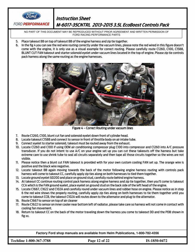
5. Place takeout BB on top of takeout BB of the engine harness and zip tie together.
6. In the fig 4 you can see the red wire routing correctly under the vacuum lines, please note the red wired in this figure doesn’t
come with the engine, it is only use as a visual example for correct routing. Please carefully route C1260, C100, C1588,
BLUNT CUT FAN takeout and starter solenoid eyelet under vacuum lines located in the top of engine. Please zip tie controls
pack harness along the same routing as the engine harnesses.
Figure Figure Figure Figure 4444 –––– Correct Routing under vacuum linesCorrect Routing under vacuum linesCorrect Routing under vacuum linesCorrect Routing under vacuum lines
7. Route C1260, C100, blunt cut fan and solenoid eyelet down front of cylinder head.
8. Locate takeout C1588 and connect to sensor in front of throttle body on air intake tube.
9. Connect eyelet to starter solenoid, takeout must be routed away from the exhaust.
10. Locate C1260 and C100 if using OEM air conditioning compressor plug C100 into compressor and C1260 into A/C pressure
transducer. If you do not intent to use A/C on your engine set up you can cut these takeouts off the harness but take
extreme care to use shrink tube to seal all circuits separately and then tape all those circuits together so the wires are not
visible.
11. Please notice then a blunt cut FAN takeout is provided with for your own custom cooling FAN set up. The orange wire is
positive and the black wire negative.
12. Locate takeout BB again moving towards the back of the motor following engine harness routing with controls pack
harness will come to takeout CC, carefully apply zip ties along on both harnesses to tied them together.
13. Locate ground eyelet GD200 and place on ground stud, carefully route behind engine harness.
14. At takeout CC continue routing control pack harness along engine harness and zip tie together, then you’ll come to takeout
CCA which is the FAN ground eyelet, place eyelet on ground stud on the back side of the left head of the engine.
15. Locate C1667, C1622 and C102A and carefully round under vacuum lines and rubber hose on engine. Please notice as in step
6 the red wire shows the properly routing, carefully apply zip ties along on both harnesses to tie them together until you
come to takeout CCB, the takeout C102A will routes down to the alternator and plug to the alternator.
16. Route C1667 to sensor on top of air cleaner
17. Route C1622 to sensor on inner cooler near bottom left of radiator, please take care so harness will not come in contact with
cooling fan movement.
18. Return to takeout CC on the back of the motor traveling down the harness you come to takeout DD and the PDB shown in
fig xx.
Instruction SheetInstruction SheetInstruction SheetInstruction Sheet
1111 MMMM----6017601760176017----35CNTRL35CNTRL35CNTRL35CNTRL 2013201320132013----2015 2015 2015 2015 3.53.53.53.5LLLL EcoBoost EcoBoost EcoBoost EcoBoost Controls PackControls PackControls PackControls Pack
NO PART OF THIS DOCUMENT MAY BE REPRODUCED WITHOUT PRIOR AGREEMENT AND WRITTEN PERMISSION OF FORD RACING PERFORMANCE PARTS
Techline 1-800-367-3788 Page 13 of 22 IS-1850-0472
Factory Ford shop manuals are available from Helm Publications, 1-800-782-4356
19. Choose a mounting location for the PDB and route the rest of the harness inside of the vehicle. Please remove the small
cover of the PDB, you will find an eyelet loosely attached to the PDB, it is CRITAL that this eyelet must remain at the same
location after the installation is completed.
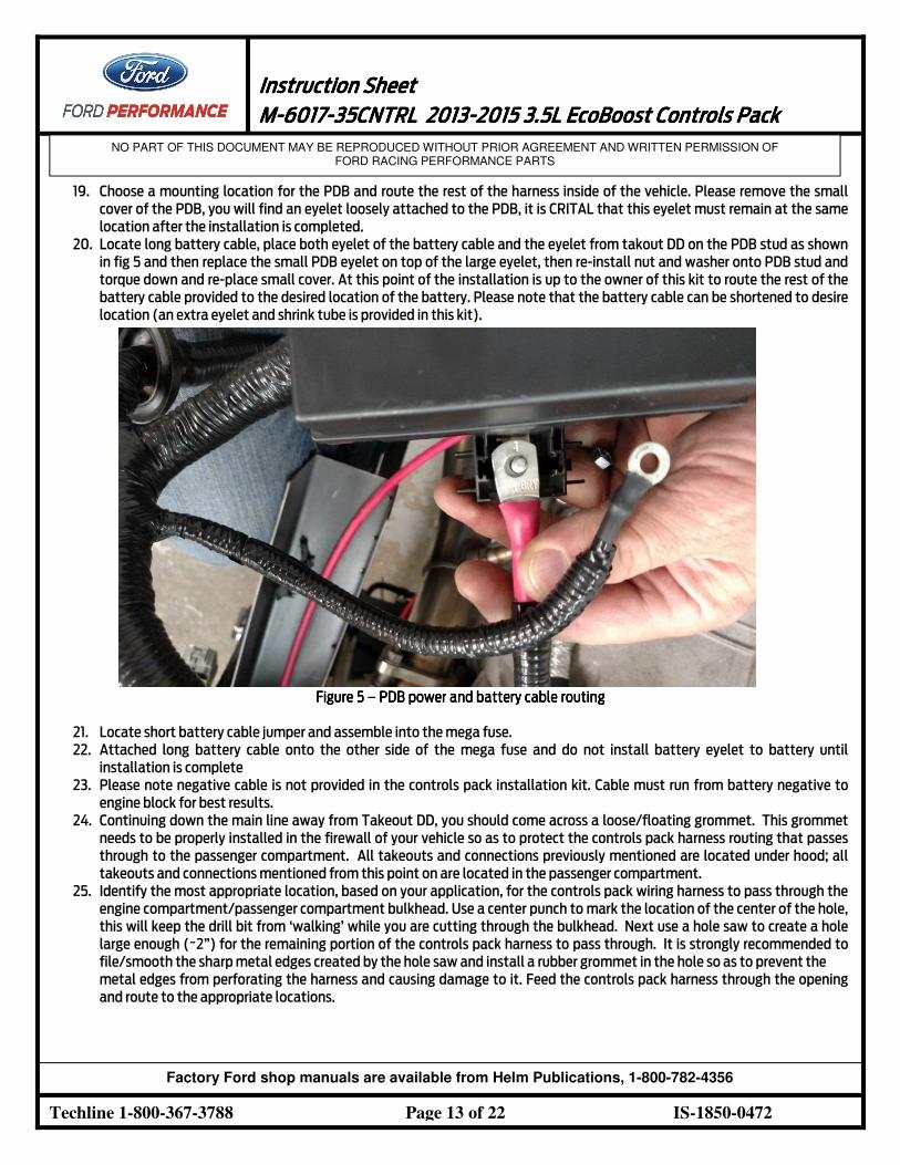
20. Locate long battery cable, place both eyelet of the battery cable and the eyelet from takout DD on the PDB stud as shown
in fig 5 and then replace the small PDB eyelet on top of the large eyelet, then re-install nut and washer onto PDB stud and
torque down and re-place small cover. At this point of the installation is up to the owner of this kit to route the rest of the
battery cable provided to the desired location of the battery. Please note that the battery cable can be shortened to desire
location (an extra eyelet and shrink tube is provided in this kit).
Figure Figure Figure Figure 5555 –––– PDBPDBPDBPDB power and battery cable routingpower and battery cable routingpower and battery cable routingpower and battery cable routing
21. Locate short battery cable jumper and assemble into the mega fuse.
22. Attached long battery cable onto the other side of the mega fuse and do not install battery eyelet to battery until
installation is complete
23. Please note negative cable is not provided in the controls pack installation kit. Cable must run from battery negative to
engine block for best results.
24. Continuing down the main line away from Takeout DD, you should come across a loose/floating grommet. This grommet
needs to be properly installed in the firewall of your vehicle so as to protect the controls pack harness routing that passes
through to the passenger compartment. All takeouts and connections previously mentioned are located under hood; all
takeouts and connections mentioned from this point on are located in the passenger compartment.
25. Identify the most appropriate location, based on your application, for the controls pack wiring harness to pass through the
engine compartment/passenger compartment bulkhead. Use a center punch to mark the location of the center of the hole,
this will keep the drill bit from ‘walking’ while you are cutting through the bulkhead. Next use a hole saw to create a hole
large enough (~2”) for the remaining portion of the controls pack harness to pass through. It is strongly recommended to
file/smooth the sharp metal edges created by the hole saw and install a rubber grommet in the hole so as to prevent the
metal edges from perforating the harness and causing damage to it. Feed the controls pack harness through the opening
and route to the appropriate locations.
Instruction SheetInstruction SheetInstruction SheetInstruction Sheet
1111 MMMM----6017601760176017----35CNTRL35CNTRL35CNTRL35CNTRL 2013201320132013----2015 2015 2015 2015 3.53.53.53.5LLLL EcoBoost EcoBoost EcoBoost EcoBoost Controls PackControls PackControls PackControls Pack
NO PART OF THIS DOCUMENT MAY BE REPRODUCED WITHOUT PRIOR AGREEMENT AND WRITTEN PERMISSION OF FORD RACING PERFORMANCE PARTS
Techline 1-800-367-3788 Page 14 of 22 IS-1850-0472
Factory Ford shop manuals are available from Helm Publications, 1-800-782-4356
26. Identify proper mounting location for the Accelerator pedal, Clutch pedal (purchased separately) and Ignition Switch
(purchased separately). Lay each component on its own piece of cardboard and use a pencil to create a template of the
footprint. Use the templates to drill holes in the proper location/orientation within the vehicle passenger compartment.
Attach components to vehicle.
27. Identify mounting location for the Bracket with OBDII connector. Be sure to complete Step 26 before you do this as you will
be limited by the harness lead length. Use a piece of paper or cardboard and a pencil to create a template of the bracket
footprint. Use the template to drill holes in the proper location/orientation within the vehicle passenger compartment.
Attach the bracket to the vehicle.
28. Moving down the main line of the controls pack harness from the loose grommet is "Takeout EE," which consists of one
routing off of the mainline:
a. Instrument Panel Pigtail connector (C160A)
29. Route C160A to approximately the base of the steering wheel to be connected as explained in a later step (Step 34).
30. Connect the ground eyelet to a reliable ground point on the chassis or engine block, away from dirt and water.
31. Located approximately 1 foot down the main line of the controls pack harness from Takeout EE is "Takeout FF" and
"Takeout GG" ,which consist of five routing off of the mainline:
a. Accelerator Pedal Position Sensor (APPS) (C2040)
b. Ground Eyelet (GD100)
c. Clutch Bottom of Travel (C257)
d. Clutch Top of Travel (C277)
e. Data Link Connector (C251)
32. Connect C2040 to the base of the accelerator pedal module.
33. Connect each of the connectors in to their respective locations.
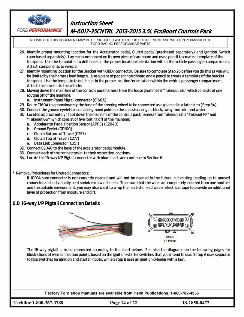
34. Locate the 16-way I/P Pigtail connector with blunt leads and continue to Section 6.
* Removal Procedures for Unused Connectors:
If 100% sure connector is not currently needed and will not be needed in the future, cut routing leading-up to unused
connector and individually heat shrink each wire herein. To ensure that the wires are completely isolated from one another
and the outside environment, you may also want to wrap the heat-shrinked wire in electrical tape to provide an additional
layer of protection from moisture and dirt.
6.0 6.0 6.0 6.0 16161616----way I/P Pigtail Connection Detailsway I/P Pigtail Connection Detailsway I/P Pigtail Connection Detailsway I/P Pigtail Connection Details
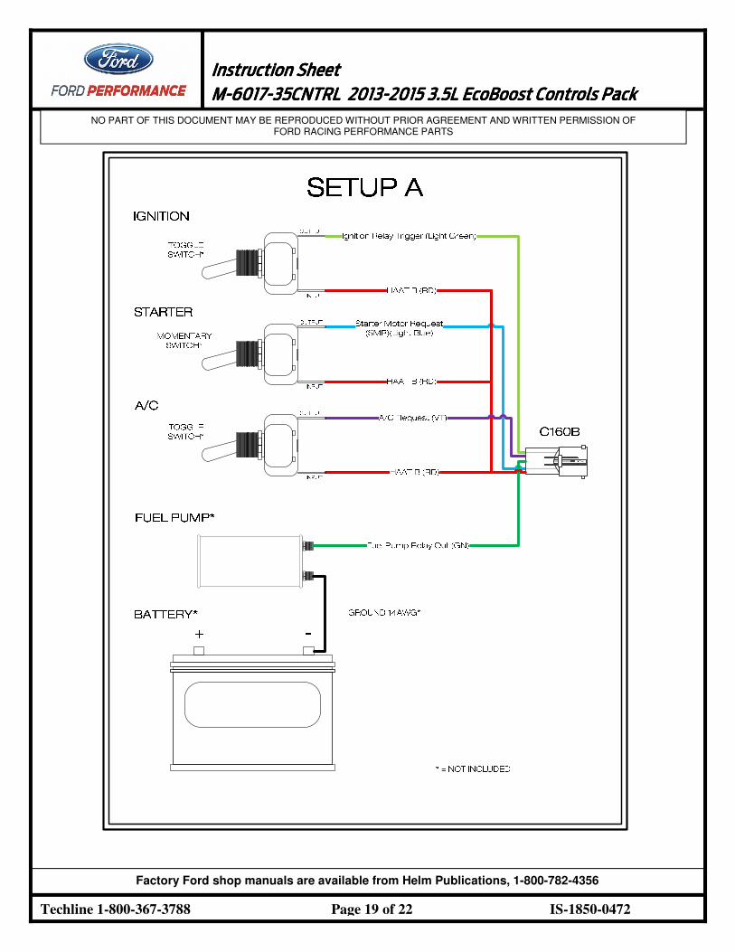
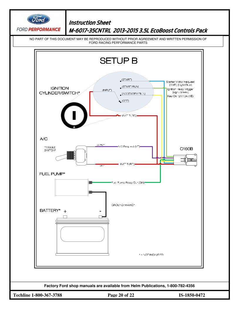
The 16-way pigtail is to be connected according to the chart below. See also the diagrams on the following pages for
illustrations of wire connection points, based on the ignition/starter switches that you intend to use. Setup A uses separate
toggle switches for ignition and starter inputs, while Setup B uses an ignition cylinder with a key.
Instruction SheetInstruction SheetInstruction SheetInstruction Sheet
1111 MMMM----6017601760176017----35CNTRL35CNTRL35CNTRL35CNTRL 2013201320132013----2015 2015 2015 2015 3.53.53.53.5LLLL EcoBoost EcoBoost EcoBoost EcoBoost Controls PackControls PackControls PackControls Pack
NO PART OF THIS DOCUMENT MAY BE REPRODUCED WITHOUT PRIOR AGREEMENT AND WRITTEN PERMISSION OF FORD RACING PERFORMANCE PARTS
Techline 1-800-367-3788 Page 15 of 22 IS-1850-0472
Factory Ford shop manuals are available from Helm Publications, 1-800-782-4356
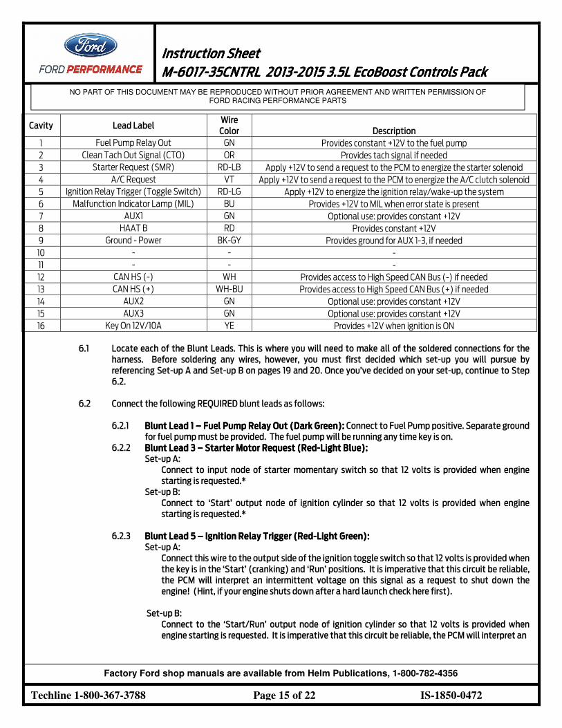
Cavity Lead Label Wire
Color Description
1 Fuel Pump Relay Out GN Provides constant +12V to the fuel pump
2 Clean Tach Out Signal (CTO) OR Provides tach signal if needed
3 Starter Request (SMR) RD-LB Apply +12V to send a request to the PCM to energize the starter solenoid
4 A/C Request VT Apply +12V to send a request to the PCM to energize the A/C clutch solenoid
5 Ignition Relay Trigger (Toggle Switch) RD-LG Apply +12V to energize the ignition relay/wake-up the system
6 Malfunction Indicator Lamp (MIL) BU Provides +12V to MIL when error state is present
7 AUX1 GN Optional use: provides constant +12V
8 HAAT B RD Provides constant +12V
9 Ground - Power BK-GY Provides ground for AUX 1-3, if needed
10 - - -
11 - - -
12 CAN HS (-) WH Provides access to High Speed CAN Bus (-) if needed
13 CAN HS (+) WH-BU Provides access to High Speed CAN Bus (+) if needed
14 AUX2 GN Optional use: provides constant +12V
15 AUX3 GN Optional use: provides constant +12V
16 Key On 12V/10A YE Provides +12V when ignition is ON
6.1 Locate each of the Blunt Leads. This is where you will need to make all of the soldered connections for the
harness. Before soldering any wires, however, you must first decided which set-up you will pursue by
referencing Set-up A and Set-up B on pages 19 and 20. Once you’ve decided on your set-up, continue to Step
6.2.
6.2 Connect the following REQUIRED blunt leads as follows:
6.2.1 Blunt Lead 1Blunt Lead 1Blunt Lead 1Blunt Lead 1 –––– Fuel Pump Fuel Pump Fuel Pump Fuel Pump Relay Out Relay Out Relay Out Relay Out (Dark Green):(Dark Green):(Dark Green):(Dark Green): Connect to Fuel Pump positive. Separate ground
for fuel pump must be provided. The fuel pump will be running any time key is on.
6.2.2 Blunt Lead 3 Blunt Lead 3 Blunt Lead 3 Blunt Lead 3 –––– Starter Motor Request (Starter Motor Request (Starter Motor Request (Starter Motor Request (RedRedRedRed----Light BlueLight BlueLight BlueLight Blue):):):):
Set-up A:
Connect to input node of starter momentary switch so that 12 volts is provided when engine
starting is requested.*
Set-up B:
Connect to ‘Start’ output node of ignition cylinder so that 12 volts is provided when engine
starting is requested.*
6.2.3 Blunt Lead Blunt Lead Blunt Lead Blunt Lead 5 5 5 5 –––– Ignition Relay Trigger (Ignition Relay Trigger (Ignition Relay Trigger (Ignition Relay Trigger (RedRedRedRed----Light Green)Light Green)Light Green)Light Green): : : :
Set-up A:
Connect this wire to the output side of the ignition toggle switch so that 12 volts is provided when
the key is in the ‘Start’ (cranking) and ‘Run’ positions. It is imperative that this circuit be reliable,
the PCM will interpret an intermittent voltage on this signal as a request to shut down the
engine! (Hint, if your engine shuts down after a hard launch check here first).
Set-up B:
Connect to the ‘Start/Run’ output node of ignition cylinder so that 12 volts is provided when
engine starting is requested. It is imperative that this circuit be reliable, the PCM will interpret an
Instruction SheetInstruction SheetInstruction SheetInstruction Sheet
1111 MMMM----6017601760176017----35CNTRL35CNTRL35CNTRL35CNTRL 2013201320132013----2015 2015 2015 2015 3.53.53.53.5LLLL EcoBoost EcoBoost EcoBoost EcoBoost Controls PackControls PackControls PackControls Pack
NO PART OF THIS DOCUMENT MAY BE REPRODUCED WITHOUT PRIOR AGREEMENT AND WRITTEN PERMISSION OF FORD RACING PERFORMANCE PARTS
Techline 1-800-367-3788 Page 16 of 22 IS-1850-0472
Factory Ford shop manuals are available from Helm Publications, 1-800-782-4356
intermittent voltage on this signal as a request to shut down the engine! (Hint, if your engine
shuts down after a hard launch check here first).
6.2.1 Blunt Lead 6 Blunt Lead 6 Blunt Lead 6 Blunt Lead 6 –––– Malfunction Indicator Light (Blue): Malfunction Indicator Light (Blue): Malfunction Indicator Light (Blue): Malfunction Indicator Light (Blue): Connect this blunt lead to the negative (black)
lead on the MIL (provided in the kit bag). You will need to provide 12V for the positive (red) lead of
the MIL.
6.2.2 Blunt Lead 8 Blunt Lead 8 Blunt Lead 8 Blunt Lead 8 –––– Hot At All Times (RedHot At All Times (RedHot At All Times (RedHot At All Times (Red):):):):
Set-up A:
Connect this lead to three different locations as needed: 1) the input node of the A/C toggle
switch, 2) the input node of the Starter momentary switch, and 3) the input node of the Ignition
toggle switch.
Set-up B:
Connect this lead to two different locations as needed: 1) the input node of the A/C toggle
switch, 2) the input node of the ignition cylinder.
6.2.3 Blunt Lead 9 Blunt Lead 9 Blunt Lead 9 Blunt Lead 9 ––––ChassisChassisChassisChassis GroundGroundGroundGround (Black(Black(Black(Black----GreyGreyGreyGrey)))):::: Connect this blunt lead to the negative (black) lead
on the MIL (provided in the kit bag).
6.2.4 Blunt Lead 16 Blunt Lead 16 Blunt Lead 16 Blunt Lead 16 –––– Key On 12V/10AKey On 12V/10AKey On 12V/10AKey On 12V/10A (Yellow(Yellow(Yellow(Yellow):):):):
Set-up A:
This lead is not needed and may be wrapped in heat shrink and electrical tape as described at the
end of Section 5.
Set-up B:
Connect to the ‘Accessory’ output node of ignition cylinder so that 12 volts is provided when key is
in ‘Accessory/Run’ mode with engine off.
6.3 Connect the following OPTIONAL blunt leads as follows:
6.3.1 Blunt Lead 2 Blunt Lead 2 Blunt Lead 2 Blunt Lead 2 –––– CTO (OrangeCTO (OrangeCTO (OrangeCTO (Orange)))):::: Optional tachometer output signal if desired.
6.3.2 Blunt Lead 4 Blunt Lead 4 Blunt Lead 4 Blunt Lead 4 –––– A/C Request (Violet)A/C Request (Violet)A/C Request (Violet)A/C Request (Violet): : : : Connect to the output of an A/C toggle switch (if desired).
Sends a request to the PCM to energize the A/C Clutch Solenoid when 12 volts is applied.
6.3.3 Blunt Lead 7 Blunt Lead 7 Blunt Lead 7 Blunt Lead 7 –––– AUX 1 (GreenAUX 1 (GreenAUX 1 (GreenAUX 1 (Green)))):::: Optional 12 volt power supply for additional aftermarket items.
Please note that if use is desired, you must add an additional fuse to the FPPDB.
6.3.4 Blunt Lead 12 Blunt Lead 12 Blunt Lead 12 Blunt Lead 12 –––– HS CAN (HS CAN (HS CAN (HS CAN (----) (White)) (White)) (White)) (White):::: Optional CAN line for additional aftermarket items.
6.3.5 Blunt Lead 13 Blunt Lead 13 Blunt Lead 13 Blunt Lead 13 –––– HS CAN (+) (WhiteHS CAN (+) (WhiteHS CAN (+) (WhiteHS CAN (+) (White----Blue)Blue)Blue)Blue):::: Optional CAN line for additional aftermarket items.
6.3.6 Blunt Lead 14Blunt Lead 14Blunt Lead 14Blunt Lead 14 –––– AUX 2 (Green)AUX 2 (Green)AUX 2 (Green)AUX 2 (Green):::: Optional 12 volt power supply for additional aftermarket items.
Please note that if use is desired, you must add an additional fuse to the FPPDB.
6.3.7 Blunt Lead 15Blunt Lead 15Blunt Lead 15Blunt Lead 15 –––– AUX 3 (GreenAUX 3 (GreenAUX 3 (GreenAUX 3 (Green)))):::: Optional 12 volt power supply for additional aftermarket items.
Please note that if use is desired, you must add an additional fuse to the FPPDB.
6.4 Once all of the blunt lead connections have been soldered onto their appropriate location, insert the 16-way
I/P Pigtail connector into C160A.
* Important Note on the Starting SystemImportant Note on the Starting SystemImportant Note on the Starting SystemImportant Note on the Starting System
This kit includes connections and installation instructions for PCM controlled engine starting; however, it is not required that the
customer utilize this option. Customers may choose to use their existing non-PCM controlled starting system if desired. If non-PCM
controlled starting is used, Step 6.2.2 may be omitted, and any unused blunt leads should be cut to ~2” length and sealed using heat
shrink.
Instruction SheetInstruction SheetInstruction SheetInstruction Sheet
1111 MMMM----6017601760176017----35CNTRL35CNTRL35CNTRL35CNTRL 2013201320132013----2015 2015 2015 2015 3.53.53.53.5LLLL EcoBoost EcoBoost EcoBoost EcoBoost Controls PackControls PackControls PackControls Pack
NO PART OF THIS DOCUMENT MAY BE REPRODUCED WITHOUT PRIOR AGREEMENT AND WRITTEN PERMISSION OF FORD RACING PERFORMANCE PARTS
Techline 1-800-367-3788 Page 17 of 22 IS-1850-0472
Factory Ford shop manuals are available from Helm Publications, 1-800-782-4356
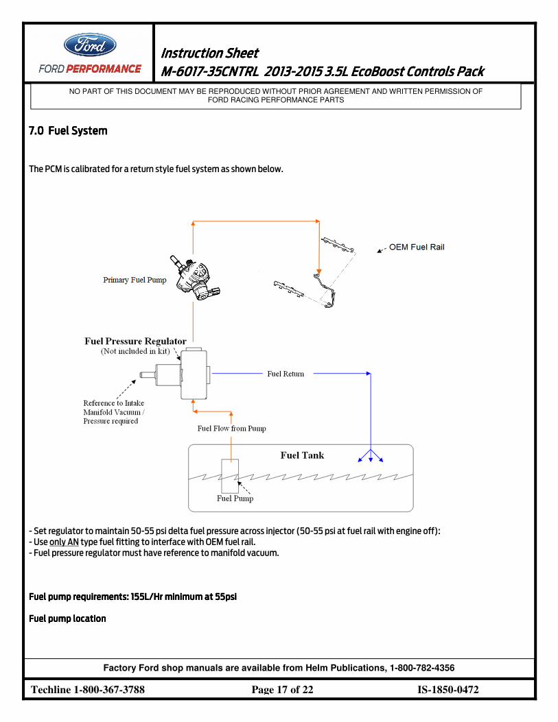
7777.0 Fuel System.0 Fuel System.0 Fuel System.0 Fuel System
The PCM is calibrated for a return style fuel system as shown below.
- Set regulator to maintain 50-55 psi delta fuel pressure across injector (50-55 psi at fuel rail with engine off):
- Use only AN type fuel fitting to interface with OEM fuel rail.
- Fuel pressure regulator must have reference to manifold vacuum.
Fuel pump requirements: Fuel pump requirements: Fuel pump requirements: Fuel pump requirements: 155L/Hr155L/Hr155L/Hr155L/Hr minimum at 55psi minimum at 55psi minimum at 55psi minimum at 55psi
Fuel pump locationFuel pump locationFuel pump locationFuel pump location
Instruction SheetInstruction SheetInstruction SheetInstruction Sheet
1111 MMMM----6017601760176017----35CNTRL35CNTRL35CNTRL35CNTRL 2013201320132013----2015 2015 2015 2015 3.53.53.53.5LLLL EcoBoost EcoBoost EcoBoost EcoBoost Controls PackControls PackControls PackControls Pack
NO PART OF THIS DOCUMENT MAY BE REPRODUCED WITHOUT PRIOR AGREEMENT AND WRITTEN PERMISSION OF FORD RACING PERFORMANCE PARTS
Techline 1-800-367-3788 Page 18 of 22 IS-1850-0472
Factory Ford shop manuals are available from Helm Publications, 1-800-782-4356
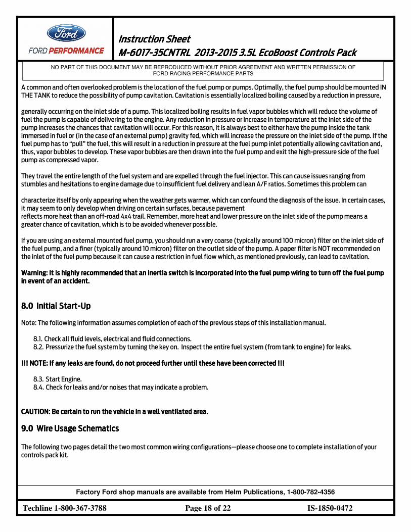
A common and often overlooked problem is the location of the fuel pump or pumps. Optimally, the fuel pump should be mounted IN
THE TANK to reduce the possibility of pump cavitation. Cavitation is essentially localized boiling caused by a reduction in pressure,
generally occurring on the inlet side of a pump. This localized boiling results in fuel vapor bubbles which will reduce the volume of
fuel the pump is capable of delivering to the engine. Any reduction in pressure or increase in temperature at the inlet side of the
pump increases the chances that cavitation will occur. For this reason, it is always best to either have the pump inside the tank
immersed in fuel or (in the case of an external pump) gravity fed, which will increase the pressure on the inlet side of the pump. If the
fuel pump has to “pull” the fuel, this will result in a reduction in pressure at the fuel pump inlet potentially allowing cavitation and,
thus, vapor bubbles to develop. These vapor bubbles are then drawn into the fuel pump and exit the high-pressure side of the fuel
pump as compressed vapor.
They travel the entire length of the fuel system and are expelled through the fuel injector. This can cause issues ranging from
stumbles and hesitations to engine damage due to insufficient fuel delivery and lean A/F ratios. Sometimes this problem can
characterize itself by only appearing when the weather gets warmer, which can confound the diagnosis of the issue. In certain cases,
it may seem to only develop when driving on certain surfaces, because pavement
reflects more heat than an off-road 4x4 trail. Remember, more heat and lower pressure on the inlet side of the pump means a
greater chance of cavitation, which is to be avoided whenever possible.
If you are using an external mounted fuel pump, you should run a very coarse (typically around 100 micron) filter on the inlet side of
the fuel pump, and a finer (typically around 10 micron) filter on the outlet side of the pump. A paper filter is NOT recommended on
the inlet of the fuel pump because it can cause a restriction in fuel flow which, as mentioned previously, can lead to cavitation.
Warning: It is highly recommended that an inertia switch is incorporated into the fuel pump wiring to turn off the fuel pump Warning: It is highly recommended that an inertia switch is incorporated into the fuel pump wiring to turn off the fuel pump Warning: It is highly recommended that an inertia switch is incorporated into the fuel pump wiring to turn off the fuel pump Warning: It is highly recommended that an inertia switch is incorporated into the fuel pump wiring to turn off the fuel pump
in event of an accident.in event of an accident.in event of an accident.in event of an accident.
8888.0 .0 .0 .0 Initial StartInitial StartInitial StartInitial Start----UUUUpppp
Note: The following information assumes completion of each of the previous steps of this installation manual.
8.1. Check all fluid levels, electrical and fluid connections.
8.2. Pressurize the fuel system by turning the key on. Inspect the entire fuel system (from tank to engine) for leaks.
!!!!!! NOTE: !! NOTE: !! NOTE: !! NOTE: If any leaks are found, do not proceed further If any leaks are found, do not proceed further If any leaks are found, do not proceed further If any leaks are found, do not proceed further until these have been corrected !!!until these have been corrected !!!until these have been corrected !!!until these have been corrected !!!
8.3. Start Engine.
8.4. Check for leaks and/or noises that may indicate a problem.
CAUTION: Be certain to run the vehicle in a well ventilated area.CAUTION: Be certain to run the vehicle in a well ventilated area.CAUTION: Be certain to run the vehicle in a well ventilated area.CAUTION: Be certain to run the vehicle in a well ventilated area.
9999.0 Wire.0 Wire.0 Wire.0 Wire Usage SchematicsUsage SchematicsUsage SchematicsUsage Schematics
The following two pages detail the two most common wiring configurations—please choose one to complete installation of your
controls pack kit.
Instruction SheetInstruction SheetInstruction SheetInstruction Sheet
1111 MMMM----6017601760176017----35CNTRL35CNTRL35CNTRL35CNTRL 2013201320132013----2015 2015 2015 2015 3.53.53.53.5LLLL EcoBoost EcoBoost EcoBoost EcoBoost Controls PackControls PackControls PackControls Pack
NO PART OF THIS DOCUMENT MAY BE REPRODUCED WITHOUT PRIOR AGREEMENT AND WRITTEN PERMISSION OF FORD RACING PERFORMANCE PARTS
Techline 1-800-367-3788 Page 19 of 22 IS-1850-0472
Factory Ford shop manuals are available from Helm Publications, 1-800-782-4356
Instruction SheetInstruction SheetInstruction SheetInstruction Sheet
1111 MMMM----6017601760176017----35CNTRL35CNTRL35CNTRL35CNTRL 2013201320132013----2015 2015 2015 2015 3.53.53.53.5LLLL EcoBoost EcoBoost EcoBoost EcoBoost Controls PackControls PackControls PackControls Pack
NO PART OF THIS DOCUMENT MAY BE REPRODUCED WITHOUT PRIOR AGREEMENT AND WRITTEN PERMISSION OF FORD RACING PERFORMANCE PARTS
Techline 1-800-367-3788 Page 20 of 22 IS-1850-0472
Factory Ford shop manuals are available from Helm Publications, 1-800-782-4356
Instruction SheetInstruction SheetInstruction SheetInstruction Sheet
1111 MMMM----6017601760176017----35CNTRL35CNTRL35CNTRL35CNTRL 2013201320132013----2015 2015 2015 2015 3.53.53.53.5LLLL EcoBoost EcoBoost EcoBoost EcoBoost Controls PackControls PackControls PackControls Pack
NO PART OF THIS DOCUMENT MAY BE REPRODUCED WITHOUT PRIOR AGREEMENT AND WRITTEN PERMISSION OF FORD RACING PERFORMANCE PARTS
Techline 1-800-367-3788 Page 21 of 22 IS-1850-0472
Factory Ford shop manuals are available from Helm Publications, 1-800-782-4356
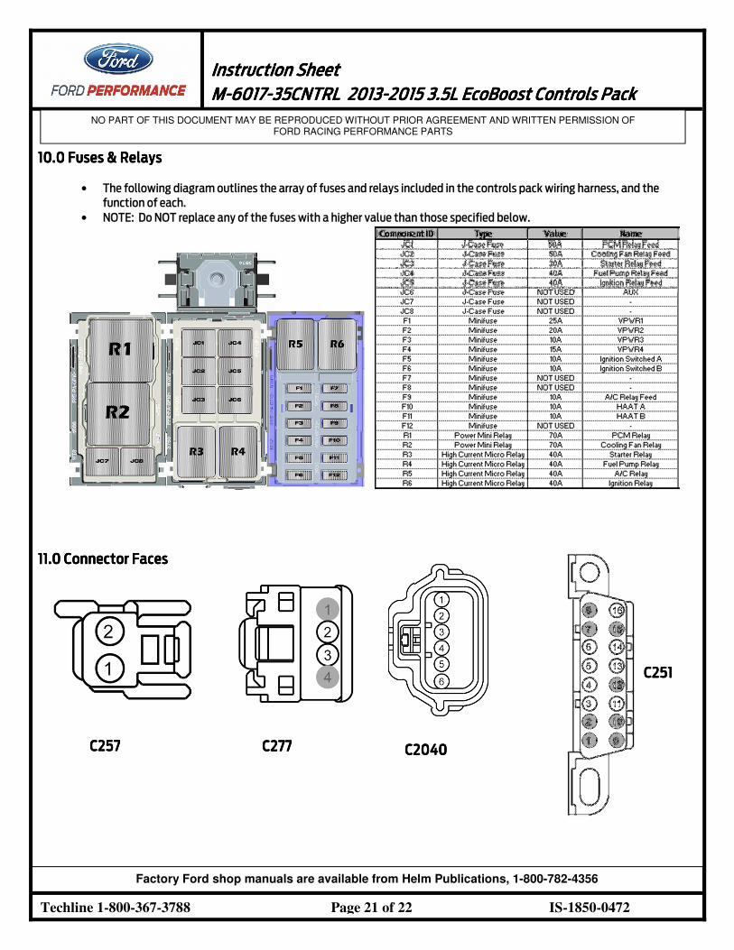
10101010.0 .0 .0 .0 FFFFuuuuses & Relaysses & Relaysses & Relaysses & Relays
• The following diagram outlines the array of fuses and relays included in the controls pack wiring harness, and the
function of each.
• NOTE: Do NOT replace any of the fuses with a higher value than those specified below.
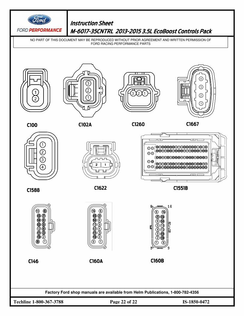
11111111.0 Connector Faces.0 Connector Faces.0 Connector Faces.0 Connector Faces
C257C257C257C257 C27C27C27C277777 C2040C2040C2040C2040
C251C251C251C251
Instruction SheetInstruction SheetInstruction SheetInstruction Sheet
1111 MMMM----6017601760176017----35CNTRL35CNTRL35CNTRL35CNTRL 2013201320132013----2015 2015 2015 2015 3.53.53.53.5LLLL EcoBoost EcoBoost EcoBoost EcoBoost Controls PackControls PackControls PackControls Pack
NO PART OF THIS DOCUMENT MAY BE REPRODUCED WITHOUT PRIOR AGREEMENT AND WRITTEN PERMISSION OF FORD RACING PERFORMANCE PARTS
Techline 1-800-367-3788 Page 22 of 22 IS-1850-0472
Factory Ford shop manuals are available from Helm Publications, 1-800-782-4356
C100C100C100C100 C102AC102AC102AC102A C1260C1260C1260C1260 C1667C1667C1667C1667
C1588C1588C1588C1588 C1622C1622C1622C1622 C1551BC1551BC1551BC1551B
C146C146C146C146 C160AC160AC160AC160A C160BC160BC160BC160B
Related Documents