3500/42M Proximitor*/Seismic Monitor Product Datasheet Bently Nevada* Asset Condition Monitoring Description The 3500/42M Proximitor*/Seismic Monitor is a four-channel monitor that accepts input from proximity and seismic transducers, conditions the signal to provide various vibrations and position measurements, and compares the conditioned signals with user-programmable alarms. You can program each channel using the 3500 Rack Configuration Software to perform the following functions: n Radial vibration n Thrust position n Differential expansion n Eccentricity n REBAM n Acceleration n Velocity n Shaft absolute n Circular acceptance region The monitor channels are programmed in pairs and can perform up to two of the listed functions at a time. For example, Channels 1 and 2 can perform one function while channels 3 and 4 perform another or the same function. The primary purpose of the 3500/42M Proximitor*/Seismic Monitor is to provide the following: n Machinery protection by continuously comparing monitored parameters against configured alarm setpoints to drive alarms n Essential machine information for both operations and maintenance personnel Each channel, depending on configuration, typically conditions its input signal to generate various parameters called static values. You can configure alert setpoints for each active static value and danger setpoints for any two of the active static values. Part Number: 143694-01 Rev. P Page 1 of 20

Welcome message from author
This document is posted to help you gain knowledge. Please leave a comment to let me know what you think about it! Share it to your friends and learn new things together.
Transcript

3500/42M Proximitor*/Seismic Monitor
Product DatasheetBently Nevada* Asset Condition Monitoring
DescriptionThe 3500/42MProximitor*/Seismic Monitor is a four-channelmonitor that accepts input fromproximity and seismictransducers, conditions the signal to provide various vibrationsand position measurements, and compares the conditionedsignals with user-programmable alarms.
You can programeach channel using the 3500RackConfiguration Software to perform the following functions:
n Radial vibrationn Thrust positionn Differential expansionn Eccentricityn REBAMn Accelerationn Velocityn Shaft absoluten Circular acceptance region
The monitor channels are programmed in pairs and can perform up totwo of the listed functions at a time. For example, Channels 1 and 2 canperform one function while channels 3 and 4 perform another or thesame function.
The primary purpose of the 3500/42MProximitor*/SeismicMonitor is to provide the following:
n Machinery protection by continuously comparing monitoredparameters against configured alarm setpoints to drive alarms
n Essential machine information for both operations and maintenancepersonnel
Each channel, depending on configuration, typically conditionsits input signal to generate various parameters called staticvalues. You can configure alert setpoints for each active staticvalue and danger setpoints for any two of the active staticvalues.
Part Number: 143694-01Rev. P
Page 1 of 20

Specifications
Inputs
SignalAccepts from 1 to 4 proximity, velocity oracceleration transducer signals
Power consumption 7.7 watts, typical
Input Impedance
Standard I/O10 kΩ(Proximitor and acceleration inputs)
Sensitivity
Radial Vibration3.94 mV/μm (100 mV/mil) or7.87 mV/μm (200 mV/mil)
Thrust3.94 mV/μm (100 mV/mil) or7.87 mV/μm (200 mV/mil)
Eccentricity3.94 mV/μm (100 mV/mil) or7.87 mV/μm (200 mV/mil)
DifferentialExpansion
0.394 mV/μm (10 mV/mil) or0.787 mV/μm (20 mV/mil)
REBAM40 mV/μm (1000 mV/mil) or80 mV/μm (2000 mV/mil)
Acceleration &Acceleration2
10 mV/ (m/s2) (100 mV/g)
Velocity & Velocity220 mV/ (mm/s) pk (500 mV/ (in/s) pk) or5.8 mV/ (mm/s) pk (145 mV/ (in/s) pk) or4 mV/ (mm/s) pk (100 mV/ (in/s) pk)
Shaft Absolute,Radial Vibration
3.94 mV/μm (100 mV/mil) or7.87 mV/μm (200 mV/mil)
Shaft absolute,Direct
3.94 mV/μm (100 mV/mil) or7.87 mV/μm (200 mV/mil)
Shaft absolute,Velocity
20 mV/ (mm/s) pk (500 mV/ (in/s) pk) or5.8 mV/ (mm/s) pk (145 mV/ (in/s) pk) or4 mV/ (mm/s) pk (100 mV/ (in/s) pk)
Circular AcceptanceRegion
See Radial Vibration on page 3.
Outputs
Front Panel LEDs
OK LEDIndicates when the 3500/42MProximitor*/Seismic Monitor is operatingproperly.
TX/RX LED
Indicates when the 3500/42MProximitor*/Seismic Monitor iscommunicating with other modules in the3500 rack.
Bypass LEDIndicates when the 3500/42MProximitor*/Seismic Monitor is in BypassMode.
BufferedTransducerOutputs
The front of each monitor has one coaxialconnector for each channel.
Each connector is short-circuit protected.
OutputImpedance
550 Ω
TransducerPower Supply
-24 Vdc
Recorder
+4 to +20 mAValues are proportional to monitor full-scale.
The monitor provides individual recordervalues for each channel.
Monitor operation is unaffected by shortcircuits on recorder outputs.
VoltageCompliance(current output)
0 to +12 Vdc range across load
Load resistance is 0 to 600 Ω.
Resolution
0.3662 µA per bit±0.25% error at room temperature±0.7% error over temperature range
Update rate approximately 100 ms or less
Shaft AbsoluteBufferedOutputs
The Shaft Absolute I/O modules have oneoutput for each channel group.
Each output is short-circuit protected.
Shaft AbsoluteOutputImpedance
300 Ω
Output supplyparameters
See Output Supply Parameters on page 9.
Part Number: 143694-01Rev. P
Page 2 of 20

Signal Conditioning
Specified at +25 ºC (+77 ºF) unless otherwise noted.
Radial Vibration
Frequency Response
Direct filter
User-programmableSingle-pole-3db at 4 Hz to 4000 Hz or1 Hz to 600 Hz± 1% accuracy
Gap filter -3 dB at 0.09 Hz
Not 1X filter
60 cpm to 15.8 times running speedConstant Q notch filterMinimum rejection in stopband of -34.9dB
Smax 0.125 to 15.8 times running speed
1X and 2X vectorfilter
Constant Q FilterMinimum rejection in stopband of -57.7dB
1X and 2X Vector, Not 1X, and Smax parameters arevalid for machine speeds of 60 cpm to 60,000 cpm.
Accuracy
Direct and GapExclusive of filteringWithin ±0.33% of full-scale typical±1% maximum
1X and 2XWithin ±0.33% of full-scale typical±1% maximum
Smax Within ±5% maximum
Not 1X
±3% for machine speeds less than 30,000cpm±8.5% for machine speeds greater than30,000 cpm
Thrust and Differential Expansion
AccuracyWithin ±0.33% of full-scale typical±1% maximum
Frequency Response
Direct filter -3 dB at 1.2 Hz
Gap filter -3 dB at 0.41 Hz
Eccentricity
AccuracyWithin ±0.33% of full-scale typical±1% maximum
Frequency Response
Direct filter -3 dB at 15.6 Hz
Gap filter -3 dB at 0.41 Hz
Acceleration
AccuracyWithin ±0.33% of full-scale typical±1% maximumExclusive of filters
Filter Quality
High-pass4-pole(80 dB per decade, 24 dB per octave)
Low-pass4-pole(80 dB per decade, 24 dB per octave)
The following table shows the frequency ranges ifboth channels of a channel pair are enabled:
Frequency Response
OutputType
Without FilterLow or HighPass Filter
With Integration
RMS 10 to 30,000 Hz 10 to 9,155 Hz 10 to 9,155 Hz
Peak 3 to 30,000 Hz 3 to 9,155 Hz 10 to 9,155 Hz
The following table shows the frequency ranges ifa single channel of a channel pair is enabled:
Frequency Response
Output TypeWithout Filter
Low or High PassFilter
With Integration
RMS 10 to 30,000 Hz 10 to 14,500 Hz
Peak 3 to 30,000 Hz 10 to 14,500 Hz
Part Number: 143694-01Rev. P
Page 3 of 20

Acceleration II
AccuracyWithin ± 0.33% of full scale typical± 1% maximumExclusive of filters
Filter Quality
High-pass4-pole(80 dB per decade, 24 dB per octave)
Low-pass4-pole(80 dB per decade, 24 dB per octave)
Frequency Response
Bias filter -3 dB at 0.01 Hz
Not OK filter -3 dB at 2400 Hz
1X and 2X vectorfilter
Valid for machine speeds of 60 cpm to100,000 cpm
The following table represents the frequencyranges for the 3500/42MProximitor*/SeismicMonitor under different options using theAcceleration II Channel Type:
Output TypeWithout Filter
Low or High PassFilter
With Integration
RMS 10 to 30,000 Hz 10 to 20,000 Hz
Peak 3 to 30,000 Hz 10 to 20,000 Hz
Velocity and Velocity II
Accuracy
Within ±0.33% of full-scale typical±1% maximum+1% -3% with MTL 764(-) Zener ExternalBarrierExclusive of filters
Velomitor* sensoraccuracy
Full Scale 0-0.5: ±3% typicalFull Scale 0-1.0: ±2% typicalFull Scale 0-2.0: ±1% typical
Velomitor sensoraccuracy withbarriers
Under radiated immunity conditions, add± 11% for all full scale ranges. The totalVelomitor sensor accuracy will be ± 15%.
Frequency Response
Bias-3dB at 0.01 HzVelocity II only
Not OK filter-3 dB at 40 HzVelocity II only
RMS 10 to 5,500 Hz, -3 dB
Peak or peak-to-peak
3 to 5,500 Hz, -3 dB
1X and 2X vectorfilter
Valid for machine speeds of 60 to 100,000cpmVelocity II only
Filter Quality
High-pass4-pole(80 dB per decade, 24 dB per octave)
Low-pass2-pole(40 dB per decade, 12 dB per octave)
Shaft Absolute, Radial Vibration
Frequency Response
Direct filterUser-programmable4 Hz to 4000 Hz or 1 Hz to 600 Hz
Gap filter -3 dB at 0.09 Hz
1X vector filterValid for machine speeds of 240 cpm to60,000 cpm
Accuracy
Direct and gapWithin ±0.33% of full-scale typical±1% maximum
1XWithin ±0.33% of full-scale typical±1% maximum
Part Number: 143694-01Rev. P
Page 4 of 20

Shaft Absolute, Velocity
AccuracyWithin ±0.33% of full scale typical±1% maximumExclusive of filters
Frequency Response
Peak orpeak-to-peak
User-programmable3 to 4,000 Hz, -3 dB
Filter Quality
High-pass2-pole(40 dB per decade, 12 dB per octave)
Low-pass2-pole(40 dB per decade, 12 dB per octave)
1X vector filterConstant Q FilterMinimum rejection in stopband of -57.7dB
Shaft Absolute Buffered Output
Accuracy ±6.0% @ 25 C
Circular acceptanceregion
See Radial Vibration on page 3.
REBAM
Frequency Response
SpikeUser-programmablefrom 0.152 to 8678 Hz
Element
User-programmable for BPFOranging from 0.139 to 3836 Hz
High-pass corner is 0.8x BPFO.Low-pass corner is 2.2x BPFO.
Rotor User programmable from 0.108 to 2221 Hz
Direct
Programmable from 3.906 to 14.2 Hz
Selection is determined by Spike andRotor filters.
GapProgrammable from 0.002 to 1.0 Hz
Selection is determined by the Rotor filter.
1X vector filter
The range of shaft speeds for which thevalue is valid depends on the nominalshaft speed for which the channel isconfigured.
The following table summarizes the relationshipbetween nominal shaft speed and the valid speedrange:
Nominal ShaftSpeed (Hz)
Valid Speed Range (Hz)
10 to <126 0.071 to 160
126 to <252 0.133 to 330
252 to <504 0.25 to 660
504 to 584 0.50 to 750
If a multi-event gear or speed wheel generates thespeed input, the upper limitation of the resultant inputsignal is approximately 20 KHz.
Filter Quality
Spike high-pass
6-pole Elliptic(155 dB per decade, minimum)
Corner frequency is -0.1 dB.
Element bandpass
8-pole Butterworth(155 dB per decade minimum)
Corner frequency is -3 dB.
Rotor low-pass
6-pole Elliptic(155 dB per decade, minimum)
Corner frequency is -0.1 dB.
Rotor, direct high-pass
1-pole Butterworth(18 dB per decade, minimum)
Corner frequency is -3 dB.
Spike, direct low-pass
Corner is -0.3 dB maximum.
Gap low-pass
1-pole Butterworth(18 dB per decade, minimum)
Corner frequency is -3 dB.
1X amplitude
Constant Q of 16.67
Stopband frequencies are 0.91 and 1.09times the running speed.
Stopband attenuation is -51 dBminimum.
Part Number: 143694-01Rev. P
Page 5 of 20
Accuracy
Amplitude
Within ±0.33% of full scale typical
±1% maximum when input signal is atthe center frequency of the proportionalvalue's passband
Phase 3 degrees error, maximum
Channels enabled
You can use certain configurations toenable only one channel of a channelpair.
See REBAM Channels on page 19.
Filter Tracking / Stepping (Requires a valid speed signal)
Initial condition Nominal filter set used
Switch fromnominal to lowerfilter set
Current shaft speed ≤ 0.9 x(nominal shaft speed)
Switch from lower tonominal filter set
Current shaft speed ≥ 0.95 x(nominal shaft speed)
Switch fromnominal to higherfilter set
Current shaft speed ≥ 1.1 x(nominal shaft speed)
Switch from higherto nominal filter set
Current shaft speed ≤ 1.05 x(Nominal Shaft Speed)
Shaft speed errorcondition
Nominal filter set used
Physical
Monitor Module (Main Board)
Dimensions(Height x Width x Depth)
241.3 mm x 24.4 mm x 241.8 mm(9.50 in x 0.96 in x 9.52 in)
Weight 0.91 kg (2.0 lb)
I/O Modules (non-barrier)
Dimensions(Height x Width x Depth)
241.3 mm x 24.4 mm x 99.1 mm(9.50 in x 0.96 in x 3.90 in)
Weight 0.20 kg (0.44 lb)
I/O Modules (barrier)
Dimensions(Height x Width x Depth)
241.3 mm x 24.4 mm x 163.1 mm(9.50 in x 0.96 in x 6.42 in)
Weight 0.46 kg (1.01 lb)
Rack Space Requirements
Monitor 1 full-height front slot
I/O Modules 1 full-height rear slot
Barrier Parameters
The following parameters apply to CSA-NRTL/Cand ATEX/IECEx approvals.
Proximitor Barrier
Circuit Parameters
Vmax (PWR) = 26.25 VVmax (SIG) = 13.65 VImax (PWR) = 110.48 mAImax (SIG) = 2.74 mARmin (PWR) = 237.6 ΩRmin (SIG) = 4985 Ω
Channel Parameters(entity)
Vmax = 27.45 VImax = 113.24 mARmin (PWR) = 237.6 ΩRmin (SIG) = 4985 Ω
Seismic Barrier
Circuit ParametersVmax (PWR) = 26.25 VImax (PWR) = 88.39 mARmin (PWR) = 297 Ω
Channel Parameters(entity)
Vmax = 26.25 VImax = 88.39 mARmin (PWR) = 297 Ω
Alarms
Alarm Setpoints
Use Rack Configuration Software to setalert levels for each value measured bythe monitor and danger setpoints for anytwo of the values measured by themonitor.
Alarms are adjustable from 0 to 100% offull-scale for each measured value.However, when the full-scale rangeexceeds the range of the transducer, therange of the transducer will limit thesetpoint.
Accuracy of alarmsetpoints
Within 0.13% of the desired value
Part Number: 143694-01Rev. P
Page 6 of 20
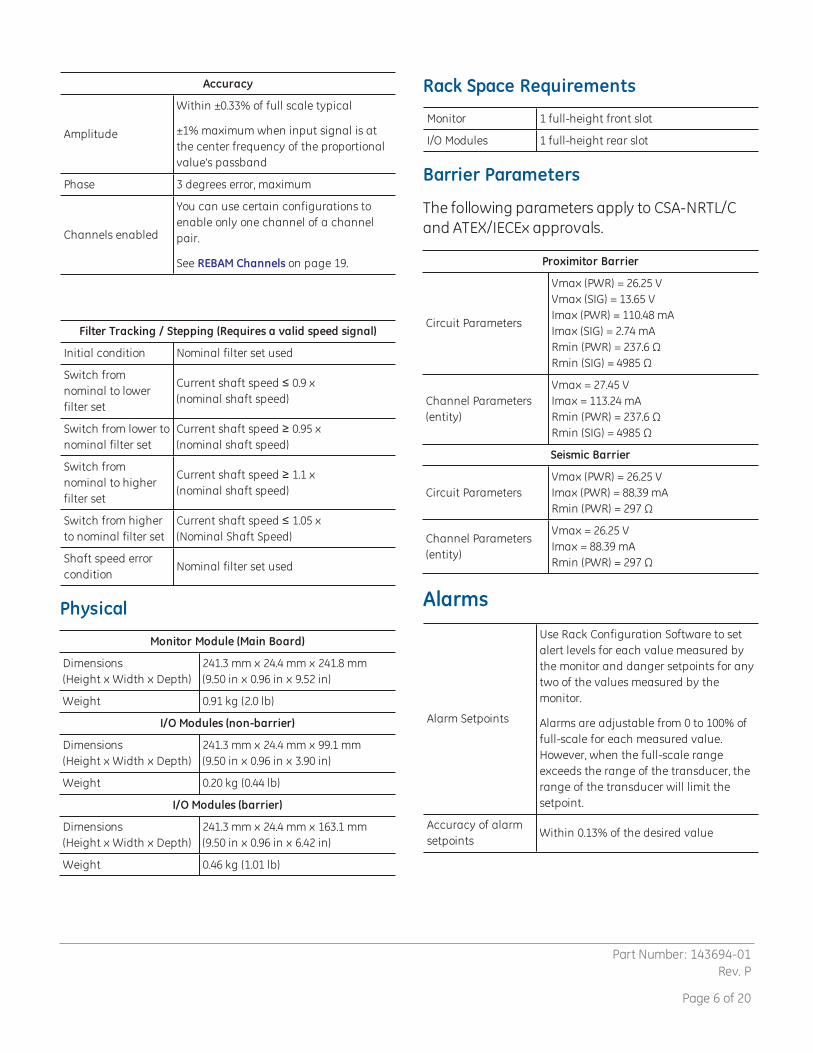
Alarm Time Delays
You can programalarmdelays using RackConfiguration Software.
For all channel pair types excludingShaft Absolute Velocity and REBAM
AlertFrom one to 60 seconds in one secondintervals
Danger0.1 seconds or from one to 60 seconds in0.5 second intervals
Shaft Absolute Velocity
AlertFrom one to 60 seconds in one secondintervals
Danger0.1 seconds or from one to 60 seconds in0.5 second intervals
REBAM
AlertFrom the calculated minimum value to400 seconds in one second intervals
DangerFrom the calculated minimum value to400 seconds in 0.5 second intervals
Static Values
Static values aremeasurements used to monitorthemachine. The 3500/42MProximitor*/SeismicMonitor returns the following static values:
Radial Vibration
Direct, Gap, 1X Amplitude, 1XPhase Lag, 2X Amplitude, 2XPhase Lag, Not 1X Amplitude andSmax Amplitude
Thrust Position Direct, Gap
DifferentialExpansion
Direct, Gap
EccentricityPeak-to-peak, Gap,Direct Minimum, Direct Maximum
REBAMSpike, Element, Rotor, Direct, Gap,1X Amplitude, 1X Phase Lag
Acceleration
Direct
Defined as one of the following:RMS Acceleration, Peak Acceleration, RMSVelocity, Peak Velocity, Band-pass peakAcceleration, or Band-pass peak Velocity
Acceleration II
Direct, 1X Amplitude and 2X Amplitude
Defined as one of the following:RMS Acceleration, Peak Acceleration, RMSVelocity, Peak Velocity, Band-pass peakAcceleration, or Band-pass peak Velocity
Additionally, 1X Phase, 2X Phase and BiasVoltage
Velocity
Direct
Defined as one of the following:RMS Velocity, Peak Velocity, peak-to-peakDisplacement, Band-pass peak Velocity,Band-pass, or Peak-to-peakDisplacement
Velocity II
Direct, 1X Amplitud and 2X Amplitude
Defined as one of the following:RMS Velocity, Peak Velocity, peak-to-peakDisplacement, Band-pass peak Velocity,Band-pass, or Peak-to-peakDisplacement
Additionally, 1X Phase, 2X Phase and BiasVoltage
Shaft Absolute,Radial Vibrationand Shaft Absolute,Velocity
Direct, Gap, 1X Amplitude, 1X Phase Lag
Circular AcceptanceRegion
Direct, Gap, 1X Amplitude, 1X Phase Lag,1X Circular Acceptance Radius, 2XAmplitude, 2X Phase Lag, 2X CircularAcceptance Radius
Part Number: 143694-01Rev. P
Page 7 of 20

Hazardous Area ApprovalsFor the detailed listing of country and product specificapprovals, refer to the Approvals Quick ReferenceGuide, document 108M1756, atwww.GEmeasurement.com.
CSA/NRTL/C (Approval Option 01)
When used with I/O moduleordering options and internalbarriers
Ex nC [ia] IIC T4 GcClass I, Division 1,Groups A, B, C and D
Class I, Zone 2/0AEx nC [ia] IIC T4 GcClass I, Division 1Groups A, B, C and D
T4 @ Ta = -20 °C ≤ Ta ≤ +65 °C(-4 °F ≤ Ta ≤ +149 °F)per drawing 138547
When used with I/O moduleordering options withoutinternal barriers
Ex nC [L] IIC T4 GcClass I, Division 2,Groups A, B, C and D
Class I, Zone 2AEx nC IIC T4 GcClass I, Division 2Groups A, B, C and D
T4 @ Ta = -20 °C ≤ Ta ≤ +65 °C(-4 °F ≤ Ta ≤ +149 °F)per drawing 149243
ATEX/IECEx (Approval Option 02)
For ATEX/IECEx agencyapproval ordering optionswith internal barriers
II 3 (1) GEx nA nC ic [ia Ga] IIC T4 Gc
T4 @ Ta = -20 °C ≤ Ta ≤ +65 °C(-4 °F ≤ Ta ≤ +149 °F)
For ATEX/IECEx agencyapproval ordering optionswithout internal barriers
II 3 GEx nA nC ic IIC T4 Gc
T4 @ Ta = -20 °C ≤ Ta ≤ +65 °C(-4 °F ≤ Ta ≤ +149 °F)
Environmental Limits
OperatingTemperature
When used with Internal/ExternalTermination I/O Module:-30°C to +65°C(-22°F to +149°F)
When used with Internal Barrier I/OModule (Internal Termination)0°C to +65°C(32°F to +149°F)
StorageTemperature
-40°C to +85°C(-40°F to +185°F)
Humidity95%Non-condensing
Compliance and Certifications
EMC
Standards:EN 61000-6-2 Immunity for IndustrialEnvironmentsEN 61000-6-4 Emissions for IndustrialEnvironments
European Community Directives:EMC Directive 2014/30/EU
Electrical Safety
Standards:EN 61010-1
European Community Directives:LV Directive 2014/35/EU
Part Number: 143694-01Rev. P
Page 8 of 20
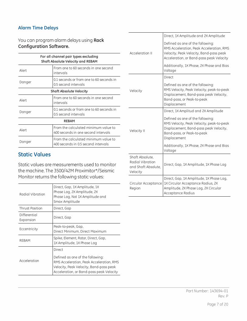
Output Supply ParametersThe following values are accurate regardless of external barrier connections.
I/O Part andOrder Options
Description Configuration
SupplyParameters
U(V)
I(mA)
P(W)
128229-01 A 01 Prox/Seismic I/O Module with Internal TerminationsProx/AccelVelomitorSeismoprobe
23.9 45.5 1.0923.9 45.5 1.096.82 2.75 0.02
128240-01 A 02Prox/Seismic I/O Module with ExternalTerminations
Prox/AccelVelomitorSeismoprobe
23.9 45.5 1.0923.9 45.5 1.096.82 2.75 0.02
138708-01 A 07Shaft Absolute I/O Module with InternalTerminations
Prox & VelomitorProx & Seismoprobe
23.9 45.5 1.096.82 45.5 0.31
138700-01 A 08Shaft Absolute I/O Modules with ExternalTerminations
Prox & VelomitorProx & Seismoprobe
23.9 45.5 1.096.82 45.5 0.31
140471-01 A 09 Prox/Velom I/O Module with Internal TerminationsProx/AccelVelomitor
23.9 45.5 1.0923.9 45.5 1.09
140482-01 A 10 Prox/Velom I/O Module with External TerminationsProx/AccelVelomitor
23.9 45.5 1.0923.9 45.5 1.09
Part Number: 143694-01Rev. P
Page 9 of 20
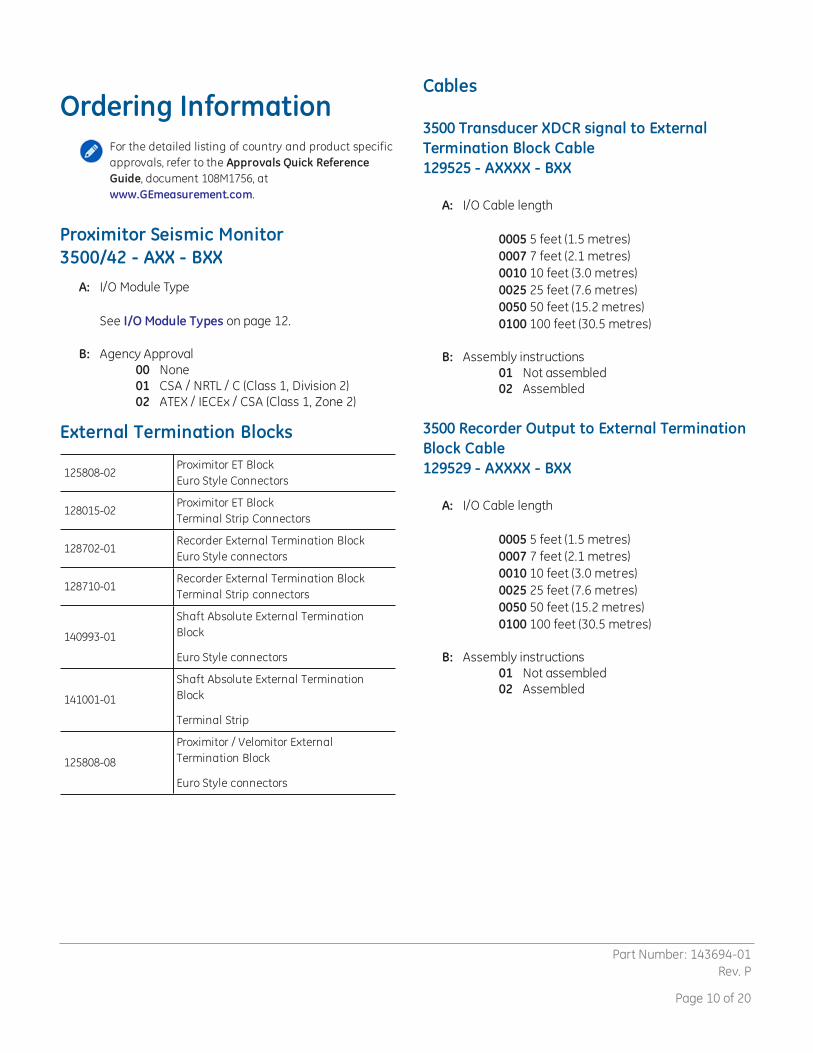
Ordering InformationFor the detailed listing of country and product specificapprovals, refer to the Approvals Quick ReferenceGuide, document 108M1756, atwww.GEmeasurement.com.
Proximitor Seismic Monitor3500/42 - AXX - BXX
A: I/O Module Type
See I/O Module Types on page 12.
B: Agency Approval00 None01 CSA / NRTL / C (Class 1, Division 2)02 ATEX / IECEx / CSA (Class 1, Zone 2)
External Termination Blocks
125808-02Proximitor ET BlockEuro Style Connectors
128015-02Proximitor ET BlockTerminal Strip Connectors
128702-01Recorder External Termination BlockEuro Style connectors
128710-01Recorder External Termination BlockTerminal Strip connectors
140993-01
Shaft Absolute External TerminationBlock
Euro Style connectors
141001-01
Shaft Absolute External TerminationBlock
Terminal Strip
125808-08
Proximitor / Velomitor ExternalTermination Block
Euro Style connectors
Cables
3500 Transducer XDCR signal to ExternalTermination Block Cable129525 - AXXXX - BXX
A: I/O Cable length
0005 5 feet (1.5 metres)0007 7 feet (2.1 metres)0010 10 feet (3.0 metres)0025 25 feet (7.6 metres)0050 50 feet (15.2 metres)0100 100 feet (30.5 metres)
B: Assembly instructions01 Not assembled02 Assembled
3500 Recorder Output to External TerminationBlock Cable129529 - AXXXX - BXX
A: I/O Cable length
0005 5 feet (1.5 metres)0007 7 feet (2.1 metres)0010 10 feet (3.0 metres)0025 25 feet (7.6 metres)0050 50 feet (15.2 metres)0100 100 feet (30.5 metres)
B: Assembly instructions01 Not assembled02 Assembled
Part Number: 143694-01Rev. P
Page 10 of 20
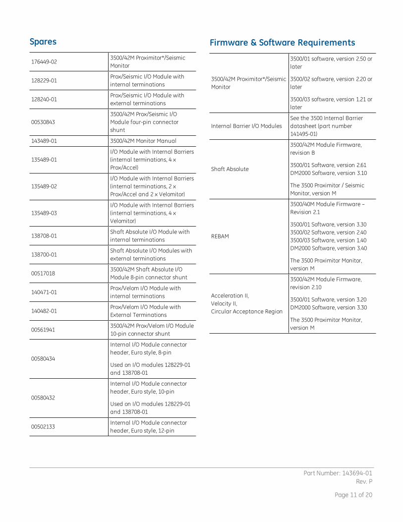
Spares
176449-023500/42M Proximitor*/SeismicMonitor
128229-01Prox/Seismic I/O Module withinternal terminations
128240-01Prox/Seismic I/O Module withexternal terminations
005308433500/42M Prox/Seismic I/OModule four-pin connectorshunt
143489-01 3500/42M Monitor Manual
135489-01I/O Module with Internal Barriers(internal terminations, 4 xProx/Accel)
135489-02I/O Module with Internal Barriers(internal terminations, 2 xProx/Accel and 2 x Velomitor)
135489-03I/O Module with Internal Barriers(internal terminations, 4 xVelomitor)
138708-01Shaft Absolute I/O Module withinternal terminations
138700-01Shaft Absolute I/O Modules withexternal terminations
005170183500/42M Shaft Absolute I/OModule 8-pin connector shunt
140471-01Prox/Velom I/O Module withinternal terminations
140482-01Prox/Velom I/O Module withExternal Terminations
005619413500/42M Prox/Velom I/O Module10-pin connector shunt
00580434
Internal I/O Module connectorheader, Euro style, 8-pin
Used on I/O modules 128229-01and 138708-01
00580432
Internal I/O Module connectorheader, Euro style, 10-pin
Used on I/O modules 128229-01and 138708-01
00502133Internal I/O Module connectorheader, Euro style, 12-pin
Firmware & Software Requirements
3500/42M Proximitor*/SeismicMonitor
3500/01 software, version 2.50 orlater
3500/02 software, version 2.20 orlater
3500/03 software, version 1.21 orlater
Internal Barrier I/O ModulesSee the 3500 Internal Barrierdatasheet (part number141495-01)
Shaft Absolute
3500/42M Module Firmware,revision B
3500/01 Software, version 2.61DM2000 Software, version 3.10
The 3500 Proximitor / SeismicMonitor, version M
REBAM
3500/40M Module Firmware –Revision 2.1
3500/01 Software, version 3.303500/02 Software, version 2.403500/03 Software, version 1.40DM2000 Software, version 3.40
The 3500 Proximitor Monitor,version M
Acceleration II,Velocity II,Circular Acceptance Region
3500/42M Module Firmware,revision 2.10
3500/01 Software, version 3.20DM2000 Software, version 3.30
The 3500 Proximitor Monitor,version M
Part Number: 143694-01Rev. P
Page 11 of 20

I/O Module TypesAXX Ordering
OptionI/O Part Number I/O Description Transducer Type
01 128229-01Prox/Seismic I/O Module withinternal terminations
Seismoprobe
Prox/Accel and Velomitor are supportedbut are not recommended.
02 128240-01Prox/Seismic I/O Module withexternal terminations
Seismoprobe
Prox/Accel and Velomitor are supportedbut are not recommended.
04 135489-01I/O Module with internal Barriers,internal terminations, 4 x Prox/Accel
Prox/Accel on channels 1 through 4
05 135489-02I/O Module with internal barriers,internal terminations, 2 x Prox/Acceland 2 x Velomitor
Prox/Accel on channels 1 and 2Velomitor on channels 3 and 4
06 135489-03I/O Module with internal barriers,internal terminations, 4 x Velomitor
Velomitor on channels 1 through 4
07 138708-01Shaft Absolute I/O Module withinternal terminations
Prox/Accel or Velomitor or Seismorprobe
08 138700-01Shaft Absolute I/O Modules withexternal terminations
Prox/Accel or Velomitor or Seismorprobe
09 140471-01Prox/Velom I/O Module with internalterminations
Prox/Accel, Velomitor or HTVS
10 140482-01Prox/Velom I/O Module withexternal terminations
Prox/Accel, Velomitor or HTVS
External termination blocks cannot be used with Internal Termination I/O Modules. When ordering I/O modules withexternal terminations, order the external termination blocks and cable separately for each I/O module.
Part Number: 143694-01Rev. P
Page 12 of 20

Graphs and FiguresThis section includes the following graphs and figures:
n The front and rear views of the 3500/42M Proximitor*/Seismic Monitor
See Front and Rear Views of 3500/42M Proximitor*/Seismic Monitor on page 14.
n The side view of the Prox / Seismic I/O Module
See Side View of I/O Modules on page 15.
n Additional I/O modules of the 3500/42M Proximitor*/Seismic Monitor
See Additional I/O Modules of the 3500/42M Proximitor*/Seismic Monitor on page 16.
n The side view of additional I/O modules
See Side View of Additional I/O Modules on page 17.
n Barrier I/O modules of the 3500/42M Proximitor*/Seismic Monitor
See Barrier I/O Modules of the 3500/42M Proximitor*/Seismic Monitor on page 18.
Part Number: 143694-01Rev. P
Page 13 of 20
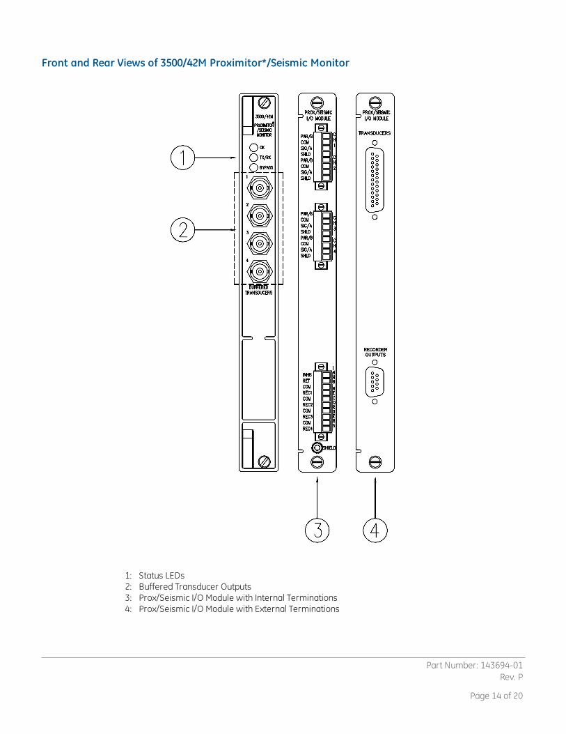
Front and Rear Views of 3500/42M Proximitor*/Seismic Monitor
1: Status LEDs2: Buffered Transducer Outputs3: Prox/Seismic I/O Module with Internal Terminations4: Prox/Seismic I/O Module with External Terminations
Part Number: 143694-01Rev. P
Page 14 of 20
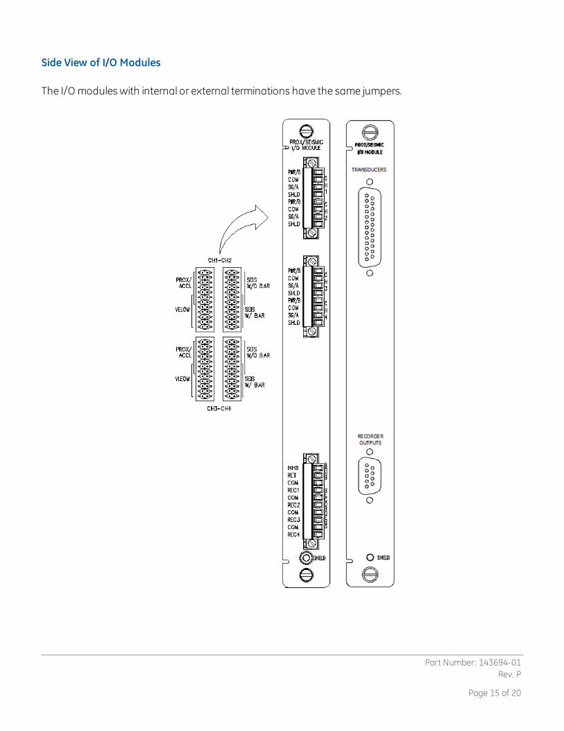
Side View of I/O Modules
The I/O modules with internal or external terminations have the same jumpers.
Part Number: 143694-01Rev. P
Page 15 of 20
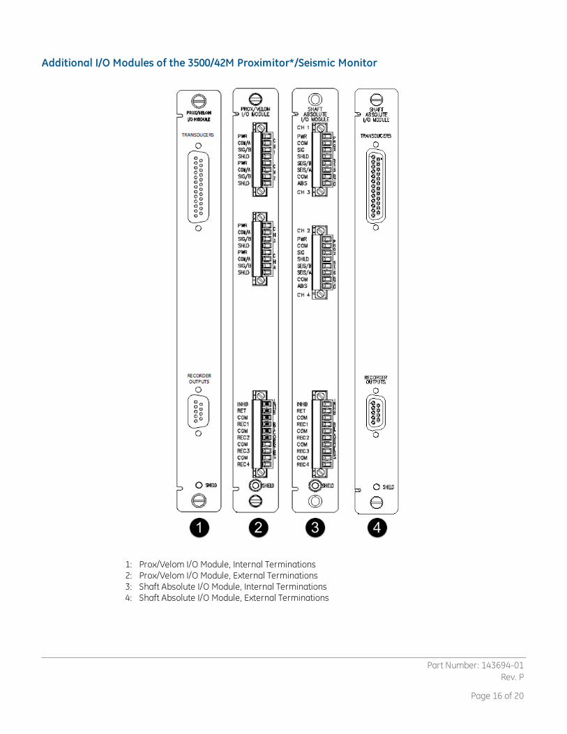
Additional I/O Modules of the 3500/42M Proximitor*/Seismic Monitor
1: Prox/Velom I/O Module, Internal Terminations2: Prox/Velom I/O Module, External Terminations3: Shaft Absolute I/O Module, Internal Terminations4: Shaft Absolute I/O Module, External Terminations
Part Number: 143694-01Rev. P
Page 16 of 20

Side View of Additional I/O Modules
Prox/Velom I/O modules and Shaft Absolute I/O modules with internal or external terminations have thesame jumpers.
Part Number: 143694-01Rev. P
Page 17 of 20

Barrier I/O Modules of the 3500/42M Proximitor*/Seismic Monitor
1: Barrier I/O Module for connecting four proximitor sensors2: Barrier I/O Module for connecting four proximitor sensors and two velomitor sensor3: Barrier I/O Module for connecting four velomitor sensors
Part Number: 143694-01Rev. P
Page 18 of 20
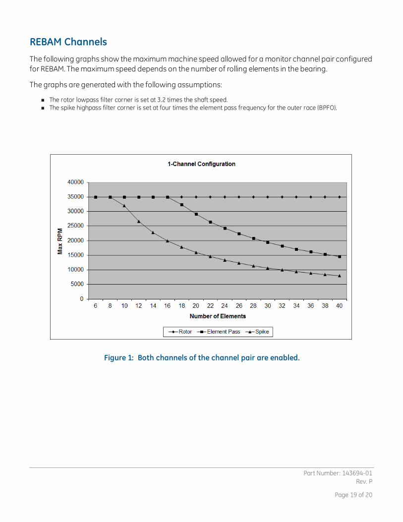
REBAM ChannelsThe following graphs show themaximummachine speed allowed for a monitor channel pair configuredfor REBAM. Themaximumspeed depends on the number of rolling elements in the bearing.
The graphs are generated with the following assumptions:
n The rotor lowpass filter corner is set at 3.2 times the shaft speed.n The spike highpass filter corner is set at four times the element pass frequency for the outer race (BPFO).
Figure 1: Both channels of the channel pair are enabled.
Part Number: 143694-01Rev. P
Page 19 of 20

Figure 2: Only one channel of a channel pair is enabled.
©1999 - 2017Bently Nevada LLC All rights reserved.* Denotes a trademark of Bently Nevada LLC, a wholly owned subsidiary of General Electric Company.
All product and company names are trademarks of their respective holders.Use of the trademarks does not imply any affiliation with or endorsement by the respective holders.
The information contained in this document is subject to changewithout prior notice.Printed in USA. Uncontrolled when transmitted electronically.1631Bently Parkway South, Minden, Nevada USA 89423Phone: 1-775.782.3611www.GEmeasurement.com
Part Number: 143694-01Rev. P
Page 20 of 20
Related Documents