3.5-D Blocking Optimization for Stencil Computations on Modern CPUs and GPUs Anthony Nguyen, Nadathur Satish, Jatin Chhugani, Changkyu Kim and Pradeep Dubey Throughput Computing Lab Intel Corporation Email: {anthony.d.nguyen,nadathur.rajagopalan.satish,jatin.chhugani,changkyu.kim,pradeep.dubey}@intel.com Abstract—Stencil computation sweeps over a spatial grid over multiple time steps to perform nearest-neighbor computations. The bandwidth-to-compute requirement for a large class of stencil kernels is very high, and their performance is bound by the available memory bandwidth. Since memory bandwidth grows slower than compute, the performance of stencil kernels will not scale with increasing compute density. We present a novel 3.5D-blocking algorithm that performs 2.5D-spatial and temporal blocking of the input grid into on-chip memory for both CPUs and GPUs. The resultant algorithm is amenable to both thread- level and data-level parallelism, and scales near-linearly with the SIMD width and multiple-cores. Our performance numbers are faster or comparable to state-of-the-art-stencil implementations on CPUs and GPUs. Our implementation of 7-point-stencil is 1.5X-faster on CPUs, and 1.8X faster on GPUs for single- precision floating point inputs than previously reported numbers. For Lattice Boltzmann methods, the corresponding speedup number on CPUs is 2.1X. I. I NTRODUCTION Stencil computation (SC) is used for a wide range of scientific and engineering disciplines [1], [2], [3], [4], [5], [6]. For a large class of SC kernels, the bandwidth-to-compute requirement is very high as a large number of bytes is needed for the few calculations. Furthermore, SC sweeps over the entire grids multiple times, evicting data from caches for 3D or higher-dimensional grids where the working set is too large even for the last-level cache. On the other hand, compute capacity has increased through core counts and wider vector (SIMD) units. Core counts will increase rapidly as the number of on-chip transistors continue to grow. The SIMD width of modern CPU and GPU processors has been steadily increasing from 128-bit in SSE architectures, 256-bit in AVX [7] to 512-bit in the upcoming Larrabee [8] architecture. GPUs have a logical 1024-bit SIMD with physical SIMD widths of 256-bits on the Nvidia GTX 200 series, increasing to 512-bits on the upcoming Fermi [9] architecture. However, memory bandwidth is increasing at a slower pace than compute. Algorithms that are bound by memory bandwidth will not scale well to future architectures. Therefore, the high memory bandwidth requirement for SC makes it especially challenging to utilize the compute density of current and upcoming architectures. In this paper, we present a novel 3.5D blocking algorithm that performs a 2.5D spatial blocking and an additional tempo- ral blocking of the input grid into on-chip memory. Our 2.5D spatial blocking blocks in two dimensions and streams through the third dimension, thereby increasing the blocking size and resulting in better utilization of the on-chip memory. The temporal blocking performs multiple time steps of SC, re-using the data blocked into on-chip memory (caches for CPUs and shared memory and register files for GPUs). This reduces the effective bandwidth requirement and allows for full utilization of the available compute resources. The resultant algorithm is amenable to both thread-level and data-level parallelism, and scales near-linearly with SIMD width and multiple cores. We apply this 3.5D blocking algorithm to two specific examples. The first example is a 7-point stencil for 3D grids. It comprises of 7 points: 1 point for the local grid site and 2 adjacent points for each of the x, y, and z dimensions. The second example uses a Lattice Boltzmann method (LBM). LBM is a class of computational fluid dynamics capable of modeling complex flow problems. It simulates the evolution of particle distribution functions over a 3D lattice over many time steps. Since LBM traverses the entire lattice in each time step to perform particle collisions and propagations, it accesses a large amount of data. The performance of previously opti- mized implementations of both 7-point stencil and LBM are bandwidth bound on state-of-the-art CPUs and GPUs. This paper makes the following contributions: • We present the most efficient blocking mechanism that reduces memory bandwidth usage and reduces overhead due to blocking. Our SC and LBM implementation is no longer memory bandwidth bound even for very large grids. • By making SC and LBM compute bound, our implemen- tation effectively utilizes the available thread- and data- level parallelism on modern processors. We scale near- linearly with multiple cores and SIMD width on both CPUs and GPUs. • We present a flexible load-balancing scheme that dis- tributes the grid elements equally amongst the available threads, all of which perform the same amount of external memory read/write and stencil computations. • We obtain the fastest implementation of 7-point stencil and LBM on a single-socket Intel Core i7 CPU for both single- and double-precision inputs. Our 7-point stencil and LBM implementations are 1.5X and 2.1X, respectively faster than the best reported numbers. As long as the cache capacity is large enough to hold the blocked data, our 3.5D blocking achieves close to peak c 2010 IEEE Personal use of this material is permitted. However, permission to reprint/republish this material for advertising or promotional purposes or for creating new collective works for resale or redistribution to servers or lists, or to reuse any copyrighted component of this work in other works must be obtained from the IEEE. SC10 November 2010, New Orleans, Louisiana, USA 978-1- 4244-7558-2/10/$26.00

Welcome message from author
This document is posted to help you gain knowledge. Please leave a comment to let me know what you think about it! Share it to your friends and learn new things together.
Transcript

3.5-D Blocking Optimization for StencilComputations on Modern CPUs and GPUs
Anthony Nguyen, Nadathur Satish, Jatin Chhugani, Changkyu Kim and Pradeep DubeyThroughput Computing Lab
Intel CorporationEmail: {anthony.d.nguyen,nadathur.rajagopalan.satish,jatin.chhugani,changkyu.kim,pradeep.dubey}@intel.com
Abstract—Stencil computation sweeps over a spatial grid overmultiple time steps to perform nearest-neighbor computations.The bandwidth-to-compute requirement for a large class ofstencil kernels is very high, and their performance is boundby the available memory bandwidth. Since memory bandwidthgrows slower than compute, the performance of stencil kernelswill not scale with increasing compute density. We present a novel3.5D-blocking algorithm that performs 2.5D-spatial and temporalblocking of the input grid into on-chip memory for both CPUsand GPUs. The resultant algorithm is amenable to both thread-level and data-level parallelism, and scales near-linearly with theSIMD width and multiple-cores. Our performance numbers arefaster or comparable to state-of-the-art-stencil implementationson CPUs and GPUs. Our implementation of 7-point-stencil is1.5X-faster on CPUs, and 1.8X faster on GPUs for single-precision floating point inputs than previously reported numbers.For Lattice Boltzmann methods, the corresponding speedupnumber on CPUs is 2.1X.
I. INTRODUCTION
Stencil computation (SC) is used for a wide range ofscientific and engineering disciplines [1], [2], [3], [4], [5], [6].For a large class of SC kernels, the bandwidth-to-computerequirement is very high as a large number of bytes is neededfor the few calculations. Furthermore, SC sweeps over theentire grids multiple times, evicting data from caches for 3Dor higher-dimensional grids where the working set is too largeeven for the last-level cache.
On the other hand, compute capacity has increased throughcore counts and wider vector (SIMD) units. Core countswill increase rapidly as the number of on-chip transistorscontinue to grow. The SIMD width of modern CPU and GPUprocessors has been steadily increasing from 128-bit in SSEarchitectures, 256-bit in AVX [7] to 512-bit in the upcomingLarrabee [8] architecture. GPUs have a logical 1024-bit SIMDwith physical SIMD widths of 256-bits on the Nvidia GTX200 series, increasing to 512-bits on the upcoming Fermi [9]architecture. However, memory bandwidth is increasing ata slower pace than compute. Algorithms that are bound bymemory bandwidth will not scale well to future architectures.Therefore, the high memory bandwidth requirement for SCmakes it especially challenging to utilize the compute densityof current and upcoming architectures.
In this paper, we present a novel 3.5D blocking algorithmthat performs a 2.5D spatial blocking and an additional tempo-ral blocking of the input grid into on-chip memory. Our 2.5Dspatial blocking blocks in two dimensions and streams through
the third dimension, thereby increasing the blocking size andresulting in better utilization of the on-chip memory. Thetemporal blocking performs multiple time steps of SC, re-usingthe data blocked into on-chip memory (caches for CPUs andshared memory and register files for GPUs). This reduces theeffective bandwidth requirement and allows for full utilizationof the available compute resources. The resultant algorithm isamenable to both thread-level and data-level parallelism, andscales near-linearly with SIMD width and multiple cores.
We apply this 3.5D blocking algorithm to two specificexamples. The first example is a 7-point stencil for 3D grids.It comprises of 7 points: 1 point for the local grid site and 2adjacent points for each of the x, y, and z dimensions. Thesecond example uses a Lattice Boltzmann method (LBM).LBM is a class of computational fluid dynamics capable ofmodeling complex flow problems. It simulates the evolutionof particle distribution functions over a 3D lattice over manytime steps. Since LBM traverses the entire lattice in each timestep to perform particle collisions and propagations, it accessesa large amount of data. The performance of previously opti-mized implementations of both 7-point stencil and LBM arebandwidth bound on state-of-the-art CPUs and GPUs.
This paper makes the following contributions:• We present the most efficient blocking mechanism that
reduces memory bandwidth usage and reduces overheaddue to blocking. Our SC and LBM implementation isno longer memory bandwidth bound even for very largegrids.
• By making SC and LBM compute bound, our implemen-tation effectively utilizes the available thread- and data-level parallelism on modern processors. We scale near-linearly with multiple cores and SIMD width on bothCPUs and GPUs.
• We present a flexible load-balancing scheme that dis-tributes the grid elements equally amongst the availablethreads, all of which perform the same amount of externalmemory read/write and stencil computations.
• We obtain the fastest implementation of 7-point stenciland LBM on a single-socket Intel Core i7 CPU forboth single- and double-precision inputs. Our 7-pointstencil and LBM implementations are 1.5X and 2.1X,respectively faster than the best reported numbers. Aslong as the cache capacity is large enough to hold theblocked data, our 3.5D blocking achieves close to peak
c©2010 IEEE Personal use of this material is permitted. However, permission to reprint/republish this material for advertising or promotional purposes or forcreating new collective works for resale or redistribution to servers or lists, or to reuse any copyrighted component of this work in other works must beobtained from the IEEE.SC10 November 2010, New Orleans, Louisiana, USA 978-1- 4244-7558-2/10/$26.00

compute throughput for both CPUs and GPUs.• On Nvidia GTX 285 GPU, our 7-point stencil for single-
precision inputs is 1.8X faster than previously reportednumbers. Our GPU implementation employs an efficientwork distribution across thread warps, thereby reducingthe overhead of parallelization.
II. RELATED WORK
Stencil computations (SC) are challenging for state-of-the-art multi-core architectures because of high memory band-width requirements. Data reuse is small and grid sizes areusually larger than caches, forcing subsequent sweeps throughthe grids to reload data. Spatial blocking [10], [11], [12], [13],[14], [15], [16], [17], [18] has been a commonly used approachto improve cache locality and expose parallelism.
Datta et al. [10], [11] propose an auto-tuning approachfor SC to select appropriate blocking parameters for severalarchitectures. Their implementation is memory bound whenrunning 4 CPU cores or more than 1 IBM Cell socket. Theirimplementation on Nvidia GTX280 is compute bound fordouble-precision results (double-precision throughput is low)but is memory bound for single precision. Similarly, Williamset al. [18] use an auto-tuning approach to optimize an LBMvariant, called LBMHD for various multi-core architectures.
Blocking in the spatial dimensions only provides limitedreuse opportunities because each grid point is used only ahandful of times. We find that spatial blocking is in generalinsufficient to turn bandwidth-bound stencils (for instance,single-precision 7-point stencil or LBM) into compute-boundalgorithms on modern CPU and GPU architectures.
There has been previous work in using temporal blockingfor SC and LBM [13], [17], [19], [20], [21], [22], [23].Habich et al. [13] block across different time steps t forLBM to reuse grid data within cache before writing back tomemory. However, they do not perform spatial blocking andtheir scheme does not extend to larger grids where XY slabsdo not fit in the last level cache. Williams et al. [21] performs4D blocking of SC on IBM Cell architecture and parallelizesacross 4D trapezoids. In contrast, we propose a 3.5D blockingscheme for less overhead and apply it to both SC and LBM forCPU and GPU architectures. Moreover, we perform fine-grainparallelization within an XY slab.
Parallelizing temporal blocking must be done carefullysince the blocking can introduce overlapping memory accessesand computation that must be carefully tuned to minimizeoverheads. The thread scheduling algorithm used in Habichet al. for LBM [13] and Wellein et al. for 7-point stencils [17]exposes parallelism by assigning temporal wavefronts to sev-eral threads. Their scheduling scheme has two limitations: (1)it limits the temporal blocking factor dimT to the number ofcores, limiting bandwidth gains to that number, and (2) havinga subset of cores accessing memory while other cores operat-ing within cached buffers introduces imbalance in bandwidthresource utilization, reducing effective memory bandwidth.Our scheduling is more flexible as we partition each XY sliceacross all threads, each of which reads from memory for time
step t, uses cached buffers for the intermediate time steps,and writes to memory for t + dimT − 1. Furthermore, wecan choose dimT to target the necessary bandwidth reduction,independent of the number of cores available.
Recently, there are a number of publications that map SCand LBM to graphics processing units (GPU) [15], [24],[25], [26], [27], [28], [29]. Because SC exhibits localizedcomputation, nearest neighbor interaction, and streaming dataaccesses, it maps well to GPUs with many cores, non-coherentfast memory, and high memory bandwidth. Current NvidiaGPU has a small 16KB shared memory at each multiprocessor,making tiling while keeping overhead low challenging. Toallow concurrent processing of multiple blocks, grid cells atblock boundaries must be replicated. To keep overhead low,the blocks should be sufficiently large such that the boundarycells are much fewer than the non-boundary ones.
Many publications compare highly optimized GPU im-plementations to CPU implementations that have not beenfully optimized to effectively exploit on-chip caches to reducememory bandwidth requirement. For example, when LBM isbandwidth limited, it benefits very little from on-chip paral-lelism such as SIMD vector and multiple cores. For instance,Bailey et al. [24] use CUDA on GTX8800 to deliver 28Xbetter in performance than their 4-core CPU implementationat 8.99 million lattice updates/second (MLUPS). This CPUimplementation does not scale with the number of cores anddoes not use SIMD.
III. MODERN ARCHITECTURES
For best performance of stencil computations, externalmemory bandwidth should be judiciously utilized while ex-ploiting instruction-level parallelism (ILP), thread-level paral-lelism (TLP), and data-level parallelism (DLP).
A. Memory Latency
Memory instructions must go through a virtual-to-physicaladdress translation, which is in the critical path of program ex-ecution. To improve translation speed, a translation look asidebuffer (TLB) is used to cache virtual-to-physical translationof most frequently accessed pages. If the translation is notfound in the TLB, processor pipeline stalls until the TLB missis served. Both last-level cache (LLC) and TLB misses aredifficult to hide because the miss penalty reaches more than afew hundred cycles. The LBM kernel suffers from both highTLB misses and LLC misses because of its streaming accesspatterns. At each time step, the entire lattice is brought intocache only to be evicted before any reuse. Thus, all accessesto the lattice structure always suffer external memory latencyand utilize external memory bandwidth. The large number ofstreams can result in filled up read and write buffers and cancause TLB conflicts. In later sections, we describe in detailhow to improve cache reuse and reduce external memorybandwidth usage. The 7-point stencil involves reduction opera-tions that introduce dependencies in executing a single stencilcomputation. Hence we require software techniques such as

Platform Peak BW Peak Gops Bytes/OpSP DP SP DP
Core i7 30 102 51 0.29 0.59GTX 285 159 1116 93 0.14 1.7
TABLE IPEAK BANDWIDTH (GB/SEC), PEAK COMPUTE IN SINGLE AND DOUBLE
PRECISION (GOPS), AND BYTES/OP OF CORE I7 AND GTX 285.
software pipelining and loop unrolling to increase the amountof data-level parallelism.
B. TLP/DLP
Once memory latency impact is minimized, we can exploithigh density compute resources in modern processors, whichhave integrated many cores, each with wider SIMD units.Parallelization and SIMDification are two key techniques toexploit compute resources. Parallelizing stencil computationsmust be done carefully since the blocking can introduceoverlapping memory accesses and computation that must becarefully tuned to minimize overheads. The replicated gridsites are called ghost sites and must be kept small relative tothe block size to amortize the overhead of loading extra data.This puts a limit on how small the block size can be and,consequently, on the minimum size of on-chip caches or faststorage. Parallelization overhead through synchronizations canbe significant even though all cores sit on the same chip. Tothis end, we implement our own barrier that is 50X faster thanpthreads barrier. As for exploiting SIMD, we can use SIMDunits to process multiple stencil or lattice sites concurrently.For LBM, the neighboring velocity vectors must be stored instructure-of-arrays format to enable SIMD processing withoutgathering data from disjoint regions of memory.
C. Memory Bandwidth
With the increased compute capability, the demand for dataalso increases proportionally. However, main memory band-width is growing at a lower rate than compute [30]. Therefore,we will not be able to scale up to the increasing numberof cores and wider SIMD if applications become bandwidthbound. To bridge the enormous gap between processor band-width requirements and what the memory system can provide,most processors are equipped with several levels of on-chipmemory storage (e.g., caches on CPUs and shared buffer onGPUs). If data structures being accessed fit in this storage, noexternal bandwidth is utilized, thus amplifying the effectivememory bandwidth. However, if data structures are too bigto fit in caches, we should ensure that a cache line broughtfrom the memory be fully utilized before evicted out of caches(called cache line blocking). Reorganizing data structure fromarray-of-structures to structure-of-arrays basically rearrangesdata elements so that the subsequent elements to be used alsoreside within the same cache line. Lastly, for SC, spatial andtemporal blocking of grids improves data reuse and reduceseffective memory bandwidth requirements. Blocking keeps SCkernels compute bound and allows them to scale with morecores and wider SIMD vectors.
D. System Environment
The Intel Core i7 CPU is the latest multi-threaded multi-coreIntel-Architecture processor. It offers four cores on the samedie running at a frequency of 3.2GHz. The Core i7 processorcores feature an out-of-order super-scalar micro-architecture,with newly added 2-way hyper-threading. In addition to scalarunits, it also has 4-wide SIMD units that support a wide rangeof SIMD instructions [31]. Each core has an individual 32KBL1 cache and a 256KB L2 cache. All four cores share an 8MBlast-level cache (LLC). The Core i7 processor also features anon-die memory controller that connects to three channels ofDDR memory. We measured the performance of our kernelson the Core i7 running SUSE Enterprise Server 11 with 6GBof DDR3 memory overclocked to 1333MHz.
The GTX 285 is a recent GPU from NVIDIA. It has a SIMTarchitecture with 30 streaming multiprocessors (SMs) runningat 1.55 GHz. Each SM has 8 scalar compute units for single-precision and 1 double-precision unit. Each unit is capableof performing a multiply-add (madd) op. In addition, it has aspecial function unit (SFU) typically used for transcendentaloperations in single precision.
E. Bytes-Op Ratio
We now look at the peak compute capabilities and availablememory bandwidth of modern processors and discuss whethercompute and bandwidth resources will limit performance.Table I shows the peak bandwidth and compute of the quad-core Intel Core i7 processor running at 3.2 GHz, and therecent GTX 285 GPU architecture from NVIDIA. In the table,Bytes/Op is the ratio of peak BW and peak compute ops.Here, 1 op implies 1 operation or 1 executed instruction,including arithmetic (floating point and integer) and memoryinstructions. The ops available on the GTX 285 assumes fulluse of Special Function Units and madd units - typical stenciloperations do not utilize such ops (expect for a small numberof madd ops) - hence only get a third of the peak SP computeand half of peak DP ops. This makes the actual bytes/opabout 0.43 for SP and 3.44 for DP. Note that achievablebandwidths are usually about 20-25% off from peak (we havemeasured 22 GB/s on Core i7 and 131 GB/s on GTX 285). Inthe next section, we will compare the bytes/op delivered bythe architectures with the bytes/op demand of SC kernels todiscuss the limit in performance.
IV. STENCIL KERNELS
Stencil computation (SC) performs nearest neighbor com-putation on a spatial grid. SC sweeps through the entire gridmultiple times, called time steps, updating each grid point withcalculations based on its nearest neighbors. We focus on 3Dstencils in this paper.
There are various flavors of iterative sweeps of stencilcomputation. The most commonly used is the Jacobi type,which uses two grids, one designated for reads while the otherone is designated for writes in the current time step. For thenext time step, the roles of the grids are swapped, and thegrid that was written to is now read from. Although Jacobi

Fig. 1. (a) 7-point Stencil (b) D3Q19 LBM
sweep is the most commonly used, the current implementationon modern processors is bound by the available memorybandwidth, and are the most challenging to scale and fullyutilize the increasing computational resources.
We first look at specific examples of stencils and analyzetheir compute and bandwidth requirements. We discuss thecurrent best implementations of these kernels in light of theabove analysis. Many current implementations are bound bymemory bandwidth; this motivates the need for blocking inspatial domain and across time steps (or temporal blocking),that we describe in the next section.
A. Partial Difference Equation Solvers
Partial Difference Equation (PDE) solvers are used in manyfields such as diffusion and electro-magnetics. Such solversuse stencils that have data reuse in both spatial and timedimensions [10].
1) Seven-Point Stencil: We first consider the 7-point stencil,shown in Figure 1(a), because it is simple yet exhibits thebehavior we try to address. A 7-point stencil operation can berepresented by the following equation:
Bx,y,z(t + 1) = αAx,y,z(t) + β(Ax−1,y,z(t) + Ax+1,y,z(t) +
Ax,y−1,z(t) + Ax,y+1,z(t) + Ax,y,z−1(t) + Ax,y,z+1(t))
A destination grid Bx,y,z for time step t+1 is updated with astencil that fetches a grid point from 7 points of a source arrayA for time step t: Ax,y,z and its 6 neighbors in x-1, x+1, y-1,y+1, z-1, z+1 directions. The grid point is scaled by α and itsneighbors are summed and scaled by β and both expressionsare combined. The update for each grid point involves 16 ops,of which there are 2 floating point multiplications, 6 additions,7 reads (loads) from A and 1 write (store) to B. There are atotal of 8 memory values accessed, which correspond to 32bytes in single precision (SP) and 64 bytes in double precision(DP). However, there is significant reuse of data from A acrossspatial neighbors. With spatial blocking, a chunk of data fromA can be loaded into local memory of different architecturesand reused for different computations. Each interior point (notat the boundary) in the block is reused as many times as thestencil size (7 in this case). There is thus only 1 value readfrom A from external memory and 1 value written to B, fora total of 8 bytes for SP and 16 bytes for DP. The bytes/opfor 7 point stencil is thus 0.5 for SP and 1.0 for DP.
There are two potential sources of extra data traffic. Forcache-coherence architectures like the Intel Core i7, each writeto memory first involves a fetch of the cache line from memoryand subsequent write-back traffic. This extra data transfer can
be eliminated using streaming stores to memory. However,there is also additional traffic since two ghost layers of pointsin each blocked dimension (for the plus and minus 1 points ineach dimension) needs to be brought in for computing stencilson the boundary points. These ghost layers are only loaded butnot computed on. This results in extra data traffic, hereaftercalled overestimation. The extent of the extra data traffic pergrid point depends on the dimensionality of the blocking, aswell as the block size. Hence, we advocate using a 2.5D spatialblocking scheme in Section V-A3.
2) Twenty-seven point stencil: For the 27-point stencil, eachgrid point computation involves the edge, face and cornerpoints of a 3x3x3 cube surrounding the center grid point.The edge points, corners and face neighbors are multiplied bydifferent constants. The number of ops is now 58: 4 multiplies,26 adds, 27 loads from A and 1 store to B. After spatialblocking, we still only read and write one element per stencilcomputation. Bytes/op is thus 0.14 for SP and 0.28 for DP.
B. Lattice Methods
Lattice methods work on more than one value per grid point.Shown in Figure 1(b), we use the 3-dimensional D3Q19 LBMthat works on 19 values per grid point, and produces a newset of 19 values. As opposed to the 7- and 27-point stencils inthe previous section, there is no reuse of data among differentgrid points, thus making it heavily memory bound.
In each time step, LBM performs the following actions onthe entire lattice:
1. Read 19 values from the current cell of a source array.2. Calculate new values3. Propagate the 19 new values to 18 neighboring sites
and the local site by updating a destination array.4. Swap the source and destination array. That is, the
destination array of time step t will be the source array ofthe time step t + dt.
Each cell update requires reading 19 values plus a flag arrayto find if the cell is an obstacle or boundary and writing 19values. The number of ops required for each grid cell updateis 259: 220 flops (about 12 flops per direction) plus 20 readsplus 19 writes. For SP data, the number of bytes read is 76-80bytes (depending on how the flag is stored), while 76 bytes arewritten. For efficient use of SIMD on different architectures,each of the 19 values per cell are stored in different arrays(Structure-of-Arrays configuration) rather than all together ina single array (Array-of-Structures). However, this results inwrites to some neighboring values that are not aligned tocache-line boundaries (every cell i will write to positions i+1,i−1, etc.). Streaming stores are generally not possible in suchcases. Note this does not happen in normal stencils since suchoperations only write their own values and not neighbors. Inthe absence of streaming stores, the number of bytes writtenis 152, for a total of about 228 bytes in SP (and 456 bytes inDP). Bytes/op for LBM is thus 0.88 for SP and 1.75 for DP.

C. Current Best Implementations of Stencils
Different architectures offer different bandwidth-to-computeratios, which can differ widely between SP and DP. Givena particular application, if the bytes/op of the application ishigher than the bytes/op offered by the architecture, then theapplication will be bound by memory bandwidth and anyoptimization to improve compute is ineffective until bandwidthrequirement is decreased.
LBM has high bytes/op of 0.88 for SP and 1.75 for DP.This makes the SP version bandwidth-bound on both CPU andGPU architectures (see Bytes/Op in Table I). The DP versionis bandwidth-bound on CPU but is compute-bound on GPU.The 7-point stencil has bytes/op of 0.5 for SP and 1.0 forDP. SP is bandwidth-bound on both CPU and GPU. DP isbandwidth-bound on CPU and compute-bound on GPU. The27-point stencil has low bytes/op that is sufficient to make itcompute bound on both architectures.
While spatial blocking techniques are sufficient to make27-point stencil compute bound, the bytes/op of the 7-pointand LBM kernels are much higher than the peak bytes/opavailable on the architecture. In order to further decrease thebytes/op, we advocate temporal blocking in conjunction withappropriate spatial blocking to fully utilize the architecturalcompute resources.
V. 3.5D BLOCKING (2.5D SPACE + 1D TIME)
As explained in Section IV, we focus on improving thethroughput of stencil-based kernels for which the bandwidth-to-compute ratio (γ) is greater than the corresponding peakbandwidth to peak compute ratio (Γ) of the underlyingarchitecture. The performance of such kernels is typicallybound by the available memory bandwidth, and as a result,these kernels do not completely utilize the available computepower. Although we focus on CPU and GPU, the formulationdeveloped and described in this section is applicable to a broadrange of computing devices such as Intel Larrabee [8], etc.
Notation: Let R denote the radius (in units) of extent of thestencil, usually defined as the Manhattan distance (e.g. k-pointstencil) or L∞ norm (e.g. LBM)). Let C denote the size ofthe available fast on-chip storage (LLC and registers for CPU,shared memory and registers for GPU). We assume the 3D datais laid out with the X-axis being the most frequently varyingdimension, followed by the Y- and Z-directions. Without lossof generality, let (0,0,0) (origin) denote the grid point withminimum coordinates, and NX , NY and NZ denote the inputgrid dimensions in the X, Y and Z directions respectively. LetP denote a grid point, with |P| denoting the distance of thegrid point from the origin. The size of each grid element isdenoted by E .
A. Spatial Blocking
We describe three techniques aimed at exploiting all datareuse available in the stencil operation.
Fig. 2. (a) 3D blocking (b) 2.5D blocking
1) Wavefront Blocking: Spatial Blocking techniques areaimed at completely utilizing each data element that isloaded into the on-chip storage. For stencil-based kernels, thisamounts to using a wave-front based computation pattern insteps, starting from the origin and moving diagonally away.At every step (s), the amount of data required to be residentin the on-chip memory is the set of grid points (Ps) such that(s - R)≤|Ps |≤(s + R).
This methodology suffers from two performance concerns.First, the working set increases as the wave-front approachesthe center of the grid (O(N 2
X + N 2Y + N 2
Z ) grid elements).For practical input sizes, this far exceeds the available on-chipmemory, thereby requiring multiple loads of grid elements, andincrease in corresponding memory bandwidth. Second, thread-level parallelism is extracted by evenly distributing the gridpoints amongst the threads. Because of the irregular shapeof the working set, this distribution involves computationoverhead and inter-thread communication of grid elements. Asfar as DLP is concerned, it requires gather operations since theelements are not laid out in a contiguous fashion.
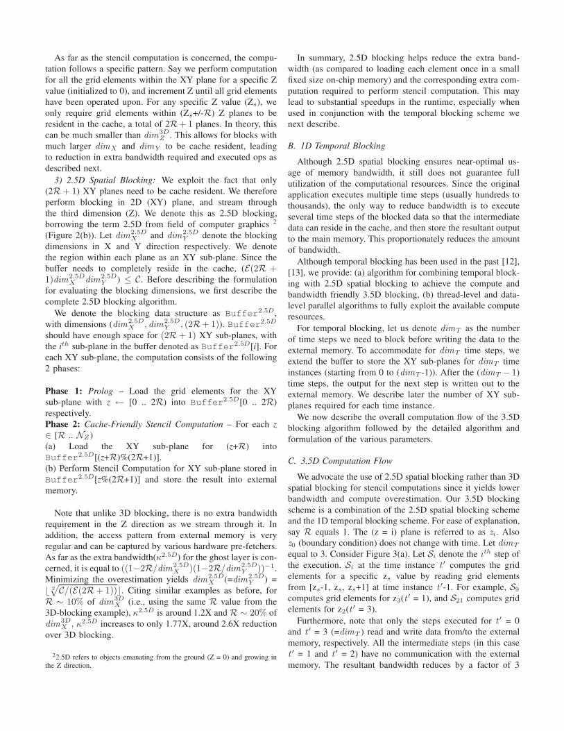
2) 3D Blocking: In contrast, a commonly used techniqueis to divide the input into overlapping axis-aligned 3D blocks(say of dimension dim
3DX , dim3D
Y , dim3DZ ) (Figure 2(a)). To
perform the computation, each block is loaded into the on-chip memory, and kernel computation is performed on gridelements that have all of their required stencil elements withinthe boundaries of the loaded block. Since the grid elementswithin distance R of the boundary (termed as ghost layer) donot satisfy this constraint, the computation is only performedfor (dim3D
X -2R)x(dim3DY -2R)x(dim3D
Z -2R) elements within ablock. Since the complete block needs to reside in the on-chipmemory, this requires (Edim
3DX dim
3DY dim
3DZ ) ≤ C. As far as
the bandwidth is concerned, the elements in the ghost layer areloaded multiple times. The ratio of extra bandwidth required(κ3D) is around 1 ((1 − 2R/dim3D
X )(1 − 2R/dim3DY )(1 −
2R/dim3DZ ))−1. The total amount of floating-point operations
performed is still the same, although the number of loadsincreases by the same factor κ3D.
In order to minimize the amount of extra bandwidth, dim3DX ,
dim3DY and dim
3DZ are set equal to each other, with each being
set to � 3
√C/E�. As evident from the formula, κ3D is inversely
proportional to R/dim3DX . For example, with R ∼ 10% of
dim3DX , κ3D is around 1.95X, and for R ∼ 20% of dim
3DX ,
κ3D increases to 4.62X, a huge overestimation.
1Since memory transfers are executed at the granularity of cache lines, theactual amount of overestimation may be larger – depending on the numberof partial cache lines loaded.
As far as the stencil computation is concerned, the compu-tation follows a specific pattern. Say we perform computationfor all the grid elements within the XY plane for a specific Zvalue (initialized to 0), and increment Z until all grid elementshave been operated upon. For any specific Z value (Zs), weonly require grid elements within (Zs+/-R) Z planes to beresident in the cache, a total of 2R+ 1 planes. In theory, thiscan be much smaller than dim
3DZ . This allows for blocks with
much larger dimX and dimY to be cache resident, leadingto reduction in extra bandwidth required and executed ops asdescribed next.
3) 2.5D Spatial Blocking: We exploit the fact that only(2R + 1) XY planes need to be cache resident. We thereforeperform blocking in 2D (XY) plane, and stream throughthe third dimension (Z). We denote this as 2.5D blocking,borrowing the term 2.5D from field of computer graphics 2
(Figure 2(b)). Let dim2.5DX and dim
2.5DY denote the blocking
dimensions in X and Y direction respectively. We denotethe region within each plane as an XY sub-plane. Since thebuffer needs to completely reside in the cache, (E(2R +1)dim2.5D
X dim2.5DY ) ≤ C. Before describing the formulation
for evaluating the blocking dimensions, we first describe thecomplete 2.5D blocking algorithm.
We denote the blocking data structure as Buffer2.5D,with dimensions (dim2.5D
X , dim2.5DY , (2R+ 1)). Buffer2.5D
should have enough space for (2R + 1) XY sub-planes, withthe ith sub-plane in the buffer denoted as Buffer2.5D[i]. Foreach XY sub-plane, the computation consists of the following2 phases:
Phase 1: Prolog – Load the grid elements for the XYsub-plane with z ← [0 .. 2R) into Buffer2.5D[0 .. 2R)respectively.Phase 2: Cache-Friendly Stencil Computation – For each z∈ [R .. NZ )(a) Load the XY sub-plane for (z+R) intoBuffer2.5D[(z+R)%(2R+1)].(b) Perform Stencil Computation for XY sub-plane stored inBuffer2.5D[z%(2R+1)] and store the result into externalmemory.
Note that unlike 3D blocking, there is no extra bandwidthrequirement in the Z direction as we stream through it. Inaddition, the access pattern from external memory is veryregular and can be captured by various hardware pre-fetchers.As far as the extra bandwidth(κ2.5D) for the ghost layer is con-cerned, it is equal to ((1−2R/dim2.5D
X )(1−2R/dim2.5DY ))−1.
Minimizing the overestimation yields dim2.5DX (=dim
2.5DY ) =
� 2
√C/(E(2R + 1))�. Citing similar examples as before, for
R ∼ 10% of dim3DX (i.e., using the same R value from the
3D-blocking example), κ2.5D is around 1.2X and R ∼ 20% ofdim
3DX , κ2.5D increases to only 1.77X, around 2.6X reduction
over 3D blocking.
22.5D refers to objects emanating from the ground (Z = 0) and growing inthe Z direction.
In summary, 2.5D blocking helps reduce the extra band-width (as compared to loading each element once in a smallfixed size on-chip memory) and the corresponding extra com-putation required to perform stencil computation. This maylead to substantial speedups in the runtime, especially whenused in conjunction with the temporal blocking scheme wenext describe.
B. 1D Temporal Blocking
Although 2.5D spatial blocking ensures near-optimal us-age of memory bandwidth, it still does not guarantee fullutilization of the computational resources. Since the originalapplication executes multiple time steps (usually hundreds tothousands), the only way to reduce bandwidth is to executeseveral time steps of the blocked data so that the intermediatedata can reside in the cache, and then store the resultant outputto the main memory. This proportionately reduces the amountof bandwidth.
Although temporal blocking has been used in the past [12],[13], we provide: (a) algorithm for combining temporal block-ing with 2.5D spatial blocking to achieve the compute andbandwidth friendly 3.5D blocking, (b) thread-level and data-level parallel algorithms to fully exploit the available computeresources.
For temporal blocking, let us denote dimT as the numberof time steps we need to block before writing the data to theexternal memory. To accommodate for dimT time steps, weextend the buffer to store the XY sub-planes for dimT timeinstances (starting from 0 to (dimT -1)). After the (dimT − 1)time steps, the output for the next step is written out to theexternal memory. We describe later the number of XY sub-planes required for each time instance.
We now describe the overall computation flow of the 3.5Dblocking algorithm followed by the detailed algorithm andformulation of the various parameters.
C. 3.5D Computation Flow
We advocate the use of 2.5D spatial blocking rather than 3Dspatial blocking for stencil computations since it yields lowerbandwidth and compute overestimation. Our 3.5D blockingscheme is a combination of the 2.5D spatial blocking schemeand the 1D temporal blocking scheme. For ease of explanation,say R equals 1. The (z = i) plane is referred to as zi. Alsoz0 (boundary condition) does not change with time. Let dimT
equal to 3. Consider Figure 3(a). Let Si denote the ith step of
the execution. Si at the time instance t′ computes the grid
elements for a specific zs value by reading grid elementsfrom [zs-1, zs, zs+1] at time instance t
′-1. For example, S9
computes grid elements for z3(t ′ = 1), and S21 computes gridelements for z2(t ′ = 3).
Furthermore, note that only the steps executed for t′ = 0
and t′ = 3 (=dimT ) read and write data from/to the external
memory, respectively. All the intermediate steps (in this caset′ = 1 and t
′ = 2) have no communication with the externalmemory. The resultant bandwidth reduces by a factor of 3

S1
S2
S3
S4
S6
S8
S11
S14
S1
S5
S7
S9
S12
S15
S19
S1
S10
S13
S16
S20
S1
S17
S21
t=0 t=1 t=2
Z=0
Z=1
Z=2
Z=3
Z=4
Z=5
Z=6
Z=7data read from the buffer
The buffer needs to maintain four sub-planes
Barrier 0
Barrier 1
......
... ...Si ith step computation for a XY sub-plane
Prolog: Computation before the Barrier0
S14,S15,S16,S17 can be executed in parallel
S18
dimy
dimx
thread0
thread1
R: radius of stencil
thread2
thread3
Stencil boundary: read-write sharing exists across different threads
Kept in memory Kept in on-chip caches Kept in memory
S18,S19,S20,S21 can be executed in parallel
Z=8
t=3
(a) 3.5D buffer management (b) Exploiting TLP
... ...
Fig. 3. (a) 3.5D Buffer management (for R=1, dimT =3) (b) Exploiting thread-level parallelism for stencil computation
(dimT in general). We now determine the number of XY sub-planes needed to be stored for each time instance. Consider astep (say S16, at t
′ = 2). This requires S7, S9 and S12 to becompletely executed. Thus we require at least 3(=(2R + 1))sub-planes for the time instances [0 .. (dimT − 1)]. However,note that this requires one time step to finish completely beforeexecuting the step at the next time instance. This scheme hastwo potential performance delimiters on current multi-/many-core platforms:
(1) Barrier Synchronization between various cores aftereach step.
(2) Limited amount of parallelism: Since there is a barrierafter each step, the only parallelism available is within thestencil computation during a step. Although this may beenough for a few cores, this scheme would not scale to theincreasing number of computational cores.
In order to scale with larger number of computational cores,we propose the following extension. Instead of storing 3 sub-planes per time instance, we can store one more (= 4) sub-planes. This ensures that one step at each time instance canbe executed in parallel with each other, including reading andwriting data from/to different buffers. Consider steps S18, S19,S20 and S21. While S18 is updating the buffer, S19 reads fromdata stored by S8, S11 and S14. Similarly S20 reads fromdata stored by S9, S12 and S15 and finally S21 reads fromdata stored by S10, S13 and S16. By storing 4 XY sub-planesper time instance, these steps can be executed in parallel.This increases the total amount of available parallelism bya factor of dimT , and also reduces the overhead of barriersynchronization. Hence for a general scenarios, we need tomaintain (dimT ) × (2R + 2) XY sub-planes in the caches.
As far as the size of each XY sub-plane is concerned, sinceall the buffers need to reside in the cache,
(E(2R + 2)dimT dim3.5DX dim
3.5DY ) ≤ C. (1)
Let us now compute the extra bandwidth required. Con-sider the ghost layer. After one time step, the grid elementswithin distance R of the boundary do not have the up-dated values. Since we perform dimT time steps, only thedata within (dim3.5D
X -2RdimT )x(dim3.5DY -2RdimT ) XY sub-
plane is correct, and needs to be written out. Hence the ratio
of extra bandwidth, or overestimation, (κ3.5D) is given by
κ3.5D = ((1−2RdimT /dim3.5DX )(1−2RdimT /dim3.5D
Y ))−1
(2)In order to maximize the use of computational resources,dimT should be greater than the ratios of the bandwidth-to-compute of the kernel (γ) to the peak bandwidth-to-computeof the machine (Γ). Hence
dimT ≥ η(= γ
Γ) (3)
Minimizing the overestimation yields
dim3.5DX = dim
3.5DY = � 2
√C/(E(2R + 2)(η))�. (4)
In addition to extra bandwidth, temporal blocking alsointroduces the overhead of extra computation that needs to beperformed repeatedly for the grid elements within the ghostlayers. The ratio of extra computation is similar to κ3.5D.
D. Exploiting Thread and Data Level Parallelism
Exploiting Thread-Level Parallelism: Let T denote thetotal number of threads. As explained in Section V-C, thebuffers are allocated in a way that we can perform independentcomputation on each time instance. Therefore, there are twodifferent ways to divide computation amongst the availablethreads:
(1) Assign each time instance to a thread. This requires abarrier after each thread is done.
(2) Divide each XY sub-plane amongst the T threads. Thereneeds to be a barrier after each round of dimT XY sub-planecomputation.
Since dimT may be much smaller than T , we advocateand have implemented (2), which scales well with increasingnumber of cores. We divide dim
3.5DY by the number of threads,
and assign each thread the relevant rows (Figure 3(b)). Incase dim
3.5DY < T , each thread gets partial rows for each
XY sub-plane. Note that this technique of dividing work alsoensures that each thread reads/writes the same amount of datafrom/to external memory and also executes similar numberof ops – thereby lending itself well to parallel implementation.

Exploiting Data-Level Parallelism: Since our 3.5D block-ing makes the stencil computation compute bound, we canfurther reduce the executed instructions by taking advantage ofthe SIMD execution units available on the modern computingunits – including both CPU and GPU. We exploit SIMDby performing stencil operation on multiple grid elementstogether. Since the grid elements are stored in a contiguousfashion, this usually involves vector load/store operations,although some of them may be from unaligned addresses,that may reduce the efficiency of execution. We describe thespecific implementation details for the two architectures inSection VI.
E. Parallel 3.5D Blocking Algorithm
We now describe the parallelized 3.5D blocking algorithm.Given the cache size (C), and the element size (E), thevarious blocking parameters (dim3.5D
X , dim3.5DY and dimT )
are computed. The XY plane is divided into overlapping XYsub-planes of dimension dim
3.5DX X dim
3.5DY . In addition,
each thread is pre-assigned a specific part of each XY sub-plane. For each XY sub-plane, the computation proceeds inthe following 3 phases:
Phase 1: Prolog – Load and perform all the stencil computa-tion required before performing z = R for t
′ = dimT . In theexample illustrated in Figure 3, this consists of performingsteps S1 .. S13 in chronological order.Phase 2: Stencil Computation – For each z ∈ [R .. (NZ
- 2dimTR)), perform the memory read (t ′ = 0) and stencilcomputation for t
′ = [1 .. dimT ]. The computation performedfor t
′ = dimT is written to external memory, while t′ = [1 ..
dimT ) write to the relevant buffer addresses. All the threadssimultaneously work on their assigned regions in the XY sub-planes for all the time instances. There is a barrier after eachthread has finished its computation before moving to the nextz. The specific zs at t
′ = t′′ is equal to z + 2R(dimT - t
′′).The Buffer index for any zs equals zs % (2R + 2).
Phase 3: Epilog – At the end of Phase 2, all XY sub-planeshave been read from external memory, and the stencil outputfor t
′ = dimT for all z < (NZ - 2dimTR)) have been writtento external memory. The remaining stencil computations arecarried out and result for t
′ = dimT for the remaining z valueswritten to external memory.
Throughout the computation, the grid elements are read,written and operated in a SIMD fashion, thereby utilizingall the computational resources. As evident from the abovealgorithm, as long as all the buffer entries reside in the on-chip memory, performing dimT time steps only requires gridelements to be read and written once from/to the externalmemory, resulting in a bytes/op ratio reduction of dimT /κ3.5D. As long as this decrease in byte/op ratio (dimT / κ3.5D)> γ/Γ, the resultant computation should completely utilize theavailable computational resources, as opposed to the originalbandwidth bound implementation.
VI. IMPLEMENTATION ON MODERN ARCHITECTURES
We now describe the specific details of our 3.5D blockingalgorithm for 7-point stencil and LBM on both CPU and GPU.For CPU, the 8MB LLC is available for blocking, while onGPU, the 16KB scratch pad and the 64KB register file is thememory available to perform the 3.5D blocking. For both 7-point stencil and LBM, R equals 1.
On CPU, we exploit thread-level parallelism using pthreads,and data-level parallelism using SSE [31]. All CPU imple-mentations use large memory pages (2 MB) to minimize TLBmisses, which improve performance between 5% and 20%. ForGPU, we use the CUDA [32] programming model to exploitboth thread and data level parallelism.
A. 7-Point Stencil
CPU Implementation:Comparing the bandwidth-to-compute ratio the kernel (γ)
from Section IV to that (Γ) of Core i7 from Table I, we seethat γ > Γ for both SP (0.5 > 0.29) and DP (1.0 > 0.59).Thus our 3.5D blocking would benefit both SP and DP.The minimum value of dimT that satisfies equation 3 is(dimT = 2). Since higher values of dimT result in increasingoverestimation, we chose (dimT = 2) for our implementation.In order to determine dim
3.5DX and dim
3.5DY , we use C equal
to 4MB (half of cache size). This is done since the cacheis used to store other data structures used by the application(and other processes), and also the loads from the externalmemory cannot bypass the cache, thereby reducing the totalsize available for the blocking data structure.
For SP, E equals 4 bytes, and hence from equation 1,we get ((4)(4)(2)dim3.5D
X dim3.5DY ) ≤ 4MB. To minimize
the overestimation factor κ3.5D, we use equation 4 and get:dim
3.5DX ≤ 361. We used dim
3.5DX = dim
3.5DY = 360. For SP,
κ3.5D evaluated to around 1.02X.The Core i7 has 4 cores. To exploit TLP, each thread was
assigned 360/4 = 90 rows in the XY sub-plane. Our method-ology for dividing rows between threads also minimizes theinter-cache communication (L1, L2), since only the boundaryrows need to read data written by other cores, thereby reducingthe inter-core communication. Since the buffer data structureis frequently accessed, we do not expect it to be evicted fromcaches, therefore the achieved performance should closelymatch the expected performance. We present performanceresults in Section VII-A. To exploit DLP, we performed stencilcomputation on 4 elements together using the single-precisionfloating point SSE instructions. Depending on the alignment ofthe memory, we did require unaligned load/store instructions.
For DP, E equals 8 bytes, which leads to dim3.5DX ≤ 256.
We used dim3.5DX = dim
3.5DX = 256. For exploiting TLP,
each thread was assigned 64 rows in the XY sub-plane. Toexploit DLP, we operated on 2 grid elements simultaneouslyusing double precision floating point SSE instructions. For DP,κ3.5D evaluated to around 1.04X.
For comparison purposes, using a 3D blocking alonewould still result in a bandwidth bound number, and a 4D(3D spatial + temporal) blocking would have resulted in a

(a) (b) (c)
Fig. 4. Performance comparisons of single and double-precision stencils (a) LBM on CPU (b) 7-point stencil on CPU and (c) 7-point stencil on GPU, fordifferent grid sizes with no-blocking, only temporal/spatial blocking and both temporal and spatial blocking (3.5D blocking).
computation overhead of 1.18X for SP, and 1.21X for DPrespectively.
GPU Implementation:For SP, because γ = 0.5 is greater than Γ = 0.14, our
3.5D blocking scheme should improve performance. For DP,because γ = 1.0 is already less than Γ = 1.7, the originalcomputation should be compute bound and cannot be furthersped up. Hence we focus on SP for the rest of this sub-section.
We use the register file (64 KB in total) to store the gridelements (similar to the stencil implementation in NvidiaSDK 3DFD [15]). Furthermore, Γ = 0.14 assumes full useof special function units, something that stencil computationcannot easily take advantage of. Hence, we use the actualcompute flops, and use dimT = 2 for our 3.5D blocking, forwhich minimizing κ3.5D reduces to dim
3.5DX ≤ 45.2.
The NVIDIA GPU architecture consists of multiple stream-ing multiprocessors, or SMs, each with multiple scalar pro-cessors that execute the same instruction in parallel. In thiswork, we view them as SIMD lanes. The GTX 285 has eightscalar processors per SM, and hence an 8-element wide SIMD.However, the logical SIMD width of the architecture is 32.Each GPU instruction works on 32 data elements (called athread warp). Global memory (GDDR) accesses on the GPUare optimized for the case that every thread in a warp loads 4/8bytes of a contiguous region of memory. For 7-point stencils,setting dim
3.5DX to a multiple of 32 enables each thread to load
the same amount of data from contiguous memory locations.Since dim
3.5DX should be less than 45.2, it is chosen to be equal
to 32, same as the warp size. Since the register file is sharedbetween the threads, each thread maintains a portion of thebuffer, namely the grid element corresponding to the specificzs value. Therefore, each thread stores 4 grid elements per timeinstance. For performing the stencil computation, each threadneeds to read the neighboring values in X and Y directionfrom the other threads within the block. Since CUDA doesnot allow for explicit inter-thread communication, we use theshared memory to communicate between threads. Specifically,each thread stores the grid element for the specific zs valuefor which the stencil computation is being performed. This isfollowed by a synchronization between threads. The threadscan then read the relevant values from the shared memoryand perform the computation. This mechanism for inter-thread
communication between threads using the shared memory isemployed for all time instances.
For t′ = dimT , only the relevant sub-set of the XY sub-
plane needs to be written to the external memory – i.e. therectangular block of (dim3.5D
X −2dimT )X(dim3.5DX −2dimT ).
Hence the threads operating in the ghost layer should notwrite out their results, which requires overhead of branchinstructions and branch divergence between the threads. Inorder to amortize the overhead of such operations, each threadreads/operates for a few Y values (instead of just one).
The resultant κ3.5D evaluates to around 1.31X.
B. LBM
CPU Implementation:The bandwidth-to-compute ratio of the kernel (γ) equals
0.88 for SP and 1.75 for DP. Thus our 3.5D blocking wouldbenefit both SP and DP implementations. Using equation 3,dimT ≥ 2.9. We chose (dimT = 3) for our implementation.
For SP, E equals 4*20 = 80 bytes (19 directionsplus a flag array), and hence equation 1 yields((80)(4)(3)dim3.5D
X dim3.5DY ) ≤ 4MB. To minimize the
overestimation factor (κ3.5D), dim3.5DX ≤ 66. We used
dim3.5DX = dim
3.5DX = 64. For SP, κ3.5D evaluates to around
1.21X. To exploit TLP, each thread was assigned 64/4 = 16rows in the XY sub-plane. This is much higher than the7-point stencil since each grid element has a size of 80 bytes.Hence the number of grid elements that can be blocked ismuch smaller, thereby leading to smaller blocking sizes, andlarger overheads.
For DP, E equals 8*20 = 160 bytes, and hence dim3.5DX =
dim3.5DX = 44. For DP, κ3.5D evaluates to around 1.34X. To
exploit TLP, each thread was assigned 44/4 = 11 rows in theXY sub-plane.
For comparison purposes, using a 3D blocking alonewould still result in a bandwidth bound number, and a 4D(3D spatial + temporal) blocking would have resulted in acomputation overhead of 2.03X for SP, and 2.71X for DP.Such large overheads imply that 4D blocking would onlyimprove the bandwidth bound numbers by a small amount(1.08X for SP, and 1.06X for DP). In comparison, using 3.5Dblocking we expect speedups to be 2.2X for SP and 2.0X forDP. In fact, these numbers match the obtained performanceresults for LBM on CPU (Section VII-B). In order to improve

the performance, we further employed techniques like loopunrolling and software pipelining that gave us a marginalimprovement in throughput. Section VII-D has a detailedanalysis on the performance improvement due to variousalgorithmic techniques.
GPU Implementation:The peak bandwidth-to-compute ratio (Γ) of GTX285 is
0.14 for SP and 1.7 for DP. So we do not expect 3.5D blockingto speedup the DP performance numbers of LBM on GTX285.However, SP should benefit from 3.5D blocking.
For SP, to completely exploit the computing resources,dimT ≥ 6.1. Using C = 16KB, and E = 160 bytes, yieldsdim
3.5DX ≤ 2, which is too small, since dim
3.5DX needs to
be greater than 2RdimT for performing any blocking. Evenusing the minimum value of dimT = 2, yields dim
3.5DX ≤ 4,
which also does not permit for blocking. We therefore did notimplement our 3.5D blocking scheme for LBM on GPU, butbelieve that with increasing cache sizes on future GPU (e.g.Fermi [9]), RdimT of two and greater can be implemented toachieve speedups in throughput.
VII. PERFORMANCE EVALUATIONS
This section evaluates the performance of 7-point stenciland LBM on the Core i7 and GTX285 processors using our3.5D blocking scheme and analyzes the measured results. Itis important to note that our GPU numbers do not include thetransfer time over the PCIe, since the kernel runs for multiple(hundreds to thousands) time steps. Thus the overhead of datatransfer is amortized across these time steps.
A. 7-point stencil
CPU: We obtained significant benefits from both spatial andtemporal blocking. Figure 4(b) shows the single and doubleprecision performance on the Core i7 with no blocking, onlyspatial blocking, and the combined blocking. We use threedata sets: a small 643 grid, a medium 2563 grid and a large5123 grid. On the small example, the entire data set fits incache, and blocking does not improve performance. In fact,there are overheads involved in block addressing that lead toslight slowdowns. For the medium and large examples, spatialblocking in itself did not obtain much benefit over no-blockingon cache-based architectures. This is because 3 XY slabs ofdata (our largest slab of 5122 DP data is 2 MB) fit wellin the 8 MB L3 cache even without explicit blocking. Bothnumbers are bandwidth bound (achieving about 21 GB/s, closeto maximum achievable bandwidth).
The addition of 3.5D blocking converted the bandwidthbound kernel to a compute bound one, resulting in aperformance that is only 15% off the performance for smallinputs. The difference is mainly due to the overestimationof compute due to ghost cells. This gives a performanceof 3,900 million updates/second, a 1.5X speed up overno-blocking, and 1.4X over spatial blocking only. Thespeedup results are similar for DP data - since both computeand bandwidth scale by a factor of 2, DP performance is
half of the SP performance. Our resultant implementationscales near-linearly with the available cores, achieving aparallel scalability of around 3.6X on 4-cores. As explainedin Section V-E, we require a barrier after writing each XYsub-plane to the external memory. We implement an efficientsoftware barrier implementation [33], and incur a negligibleoverhead due to the synchronization instructions. The SSEcode also scales well, and we achieve around 3.2X SP SSEscaling, and 1.65X DP SSE scaling.
GPU: Spatial blocking gives a large benefit of 2.8X over no-blocking for single precision data (Figure 4(c)). This is a resultof the absence of caches on GPU. If data is not explicitlytransferred from global to on-chip shared memory, then thesame data is loaded multiple times for different neighbors.However, spatially blocked code is still bandwidth bound, and3.5D blocking converts it to a compute bound kernel. Thisresults in a performance gain of 1.9X-2X, resulting in anabsolute performance of 17,100 million updates/second. ForDP data, spatial blocking is in itself sufficient to convert it toa compute bound kernel since double precision GPU ops arefar fewer than SP ops. Temporal blocking is then unnecessaryfor DP. The DP performance is 4,600 million updates/second.
B. LBM
LBM has very high bytes/op and is usually bandwidthbound even with spatial blocking.
CPU: On CPU (shown in Figure 4(a)), the no-blocking singleprecision LBM obtains a bandwidth of 20.5 GB/s, close tothe maximum achievable. This number does not change withspatial blocking since LBM does not have spatial data-reuse -thus we do not consider this version. Performing only temporalblocking results in performance gains only for small data sets(for e.g. 643), where our buffer with dim
3.5DX = dim
3.5DY =
64 fits in the LLC. For larger data sets, temporal blockingwithout spatial blocking does not help, since the necessarydata in different XY slabs cannot be kept simultaneously incache without spatial blocking.
Our 3.5D blocking results in compute-bound performance.The performance is 171 million updates/second for the 2563
grid, with around 20% drop in performance due to theoverestimation at the boundaries. The DP performance isabout half the SP performance, since it uses twice as manyflops as well as bandwidth.
GPU: No-blocking gets us a bandwidth bound performanceof 485 million updates/second for SP. Since the GTX 285does not have a large cache, we cannot maintain sufficientdata across different XY slabs for effective temporal blocking.Hence temporal blocking cannot be done. LBM in DP iscompute bound on the GPU even without blocking. We obtainabout 39 DP Gops/second, which is within 15-20% of thepeak compute bound number. Hence blocking will not improveperformance.

Fig. 5. Breakdown of (a) LBM on CPUs (b) 7-point stencil on GPUs
C. Analysis of CPU and GPU performance
In this section, we provide a breakdown of the performancegains we achieved through our various optimizations. We focuson the GPU 7-point stencil and CPU LBM as illustrativeexamples. We use SP performance results in this section, andillustrate the cumulative effect of applying optimizations oneafter the other.
The breakdown for the CPU LBM stencil is given inFigure 5(a). The base performance is parallelized no-blockingscalar code (without SSE) which gives a performance of 52million updates/second. This number is bound by compute, butdoes not use SSE units. However, using 4-wide SSE instruc-tions (second bar) only improves performance to 87 millionupdates/second (and not by 4X) because the performance nowbecomes limited by memory bandwidth and not the numberof instructions.
Performing spatial blocking alone (third bar) does not helpat this stage, since there is no spatial data reuse and henceno reduction in memory bandwidth. Performing 4D blockingreduces the bandwidth due to temporal reuse of data. However,it introduces a large overhead of around 2.03X and theperformance only improves by 8%. Performing 3.5D blockingreduces the overestimation, and we get a performance of 157million updates/second. Finally, we perform optimizations toincrease ILP (such as unrolling and software prefetching). Thistakes to performance to the final 171 million updates/second.
Figure 5(b) provides the breakdown for GPU 7-point stencil.We start with a performance of 3,300 million grid pointupdates/second for naive no-blocking code. As explained inSection VII-A, this results in unnecessary bandwidth use.The second bar is spatial blocking, which brings down theelements read to about one per element – there is a bandwidthoverestimation of 13%. Spatial blocking yields a performanceof 9,234 million updates/second. The third bar denotes 4D(3D spatial + 1D temporal) blocking, for comparison purposewith our 3.5D blocking scheme. 3D spatial blocking leadsto a smaller blocking dimension, resulting in high overesti-mation, and the resultant 4D performance only improves toaround 9,700 million updates/second (at improvement of 5%).The fourth bar is our 3.5D blocking scheme, which resultsin a performance of around 13,252 million updates/second.Once the kernel is made compute bound, we increase the
instruction level parallelism by loop unrolling. This gives us aperformance of 14,345 million updates/second. The final stepis then to decrease the number of instructions. We noticedthat a number of instructions were spent in conditional checksfor boundaries, computation of loop indices and so on, whichare essentially per-thread overheads. We decreased the numberof such instructions by making each thread perform morethan one update, resulting in amortization of such overhead.This final step took our performance to 17,115 million up-dates/second.
D. Comparison with other stencil implementations
CPU: For 7-point stencil with DP, Datta [10] has reportedthe fastest performance of around 1,000 million updates on asingle-socket 2.66GHz Intel Xeon X5550 with a bandwidth ofaround 16.5 GB/s. This performance number matches closelywith our no-blocking bandwidth-bound number in Figure 4(b)after normalizing to our machine specs by scaling their numberby the ratio of our and their memory bandwidth (1000 ∗22/16.5 = 1333). In comparison, our 3.5D blocking perfor-mance is around 1,995 million updates/sec, an improvementof 1.5X over this normalized number. For 7-Point stencil withSP, the best reported performance is bandwidth bound, andcannot be improved unless using temporal blocking as in our3.5D blocking scheme. Our performance using 3.5D blockingis around 4,000 million updates/second, an improvement ofaround 1.5X.
For LBM with DP, Habich et al. [13] report a performanceof around 64 MLUPS on dual-socket (8-core) 2.66GHz IntelNehalem. To normalize this number to our single-socket3.2GHz Nehalem, we scale by 0.5 (for single socket) andthen by 3.2GHz/2.66GHz (assuming compute bound) toget 38.5 MLUPS. In comparison, our 4-core number isaround 80 MLUPS, which is around 2.08X faster than theirimplementation (using the normalized number). For LBMwith SP, our 3.5D blocking improves the bandwidth boundperformance of 87 million updates to around 180 millionupdates – an improvement of around 2.1X.
GPU: For 7-Point stencil with DP, Datta et al. [11] report aperformance of around 4,500 million updates/sec on NvidiaGTX280. The reported performance is compute-bound, Incomparison, our performance on GTX285 is around 4,600million updates/sec, which is around 10-15% slower than theirperformance (normalizing to our platform). Note that we havenot used any temporal blocking since the spatial blocking isclose to compute bound and would not benefit from our 3.5Dblocking scheme. For 7-Point stencil with SP, the performanceis bandwidth bound without temporal blocking. Our 3.5Dblocking scheme improves the performance by around 1.8X,and the resultant performance is within 30% of the peakcompute-bound performance – the difference being becauseof overestimation of the compute due to the small blockdimensions.
LBM with DP is compute bound with spatial blockingitself. Hence our 3.5D blocking does not improve it any

further. However, the SP variant is indeed bandwidth bound,but due to the small size of on-chip memory, the blockingdimensions are too small to give any speedup for this kernel.
VIII. DISCUSSION
Future architecture trend of decreasing bandwidth-to-compute ratio (Γ): Intel Westmere CPU [34] has a lowerΓ than the current Nehalem architecture, and this trend ofdecreasing peak bandwidth-to-compute ratio is expected tocontinue well into the future. Therefore our 3.5D blockingwould become even more important for stencil based kernels– requiring larger temporal blocking to exploit the increasingcompute resources. A larger temporal blocking also requiresa proportionately larger on-chip cache to reduce the overheadof 3.5D blocking.
Small GPU Cache size: For stencil kernels with large Ror E , the size of shared memory and register file is toosmall for temporal blocking to provide speedups in runtime.For example, LBM SP is currently bandwidth bound, butrequires an order of magnitude larger cache for 3.5D blockingto improve performance. Lastest and future GPUs (e.g.Fermi [9]) have a much larger cache than GTX285, andkernels like LBM SP should benefit from our blockingalgorithm.
Double-Precision on GPU: Due to the low compute densityof DP on GPU, most of the stencil kernels are compute-bound,and much slower than the corresponding SP performance (with3.5D blocking). Since the GPU Fermi architecture is expectedto increase the DP compute, we believe 3.5D blocking wouldbe required for DP stencil kernels on GPU too. On CPU, sincepeak DP throughput is half of the peak SP throughput, wealready see the benefit of 3.5D blocking for both the stencilkernels analyzed in this paper – LBM and 7-Point Stencil.
IX. CONCLUSIONS
In this paper, we propose and implement a 3.5D blockingscheme for stencil kernels by performing a 2.5D spatial and1D temporal blocking to convert bandwidth bound kernelsinto compute bound kernels. The resultant stencil computationscales well with increasing core counts and is also able toexploit data-level parallelism using SIMD operations. Addi-tionally, we provide a framework that determines the variousblocking parameters – given the byte/op of the kernel, peakbytes/op of the architecture and the on-chip caches availableto hold the blocked data. As a result, the performance of 7-point stencil and LBM is comparable or better than the fastestreported in the literature for both CPUs and GPUs. With thefuture architectural trend of increasing compute to bandwidthratio, our 3.5D blocking scheme would become even moreimportant for stencil based kernels.
REFERENCES
[1] M. Berger and J. Oliger, “Adaptive mesh refinement for hyperbolicpartial differential equations,” Journal of Computational Physics, vol. 53,no. 1, pp. 484–512, 1984.
[2] R. Bleck, C. Rooth, D. Hu, and L. T. Smith, “Salinity-driven thermoclinetransients in a wind- and thermohaline-forces isopycnic coordinatemodel of the north atlantic,” Journal of Physical Oceanography, vol. 22,no. 12, pp. 1486–1505, 1992.
[3] H. Dursun, K. ichi Nomura, L. Peng, R. Seymour, W. Wang, R. K. Kalia,A. Nakano, and P. Vashishta, “A multilevel parallelization framework forhigh-order stencil computations,” in Euro-Par, 2009, pp. 642–653.
[4] A. Nakano, P. Vashishta, and R. K. Kalra, “Multiresolution moleculardynamics for realistic materials modeling on parallel computers,” Com-puter Physics Communications, vol. 83, no. 1, pp. 197–214, 1994.
[5] L. Renganarayanan, M. Harthikote-Matha, R. Dewri, and S. V. Rajopad-hye, “Towards optimal multi-level tiling for stencil computations,” inIPDPS, 2007, pp. 1–10.
[6] F. Shimojo, R. K. Kalia, A. Nakano, and P. Vashishta, “Divide-andconquer density functional theory on hierarchical real-space grids:parallel implementationa and applications,” Physical Review, vol. B,no. 77, pp. 1–12, 2008.
[7] “Intel Advanced Vector Extensions Programming Reference,”http://softwarecommunity.intel.com/isn/downloads/intelavx/Intel−AVX−Programming−Reference−31943302.pdf, 2008.
[8] L. Seiler, D. Carmean, E. Sprangle, T. Forsyth, M. Abrash, P. Dubey,S. Junkins, A. Lake, J. Sugerman, R. Cavin, R. Espasa, E. Grochowski,T. Juan, and P. Hanrahan, “Larrabee: a many-core x86 architecture forvisual computing,” ACM Trans. Graph., vol. 27, no. 3, pp. 1–15, August2008.
[9] Nikolaj Leischner and Vitaly Osipov and Peter Sanders,“Fermi Architecture White Paper,” 2009. [Online]. Available:http://www.nvidia.com/content/PDF/fermi white papers/NVIDIA FermiCompute Architecture Whitepaper.pdf
[10] K. Datta, “Auto-tuning stencil codes for cache-basedmulticore platforms,” Ph.D. dissertation, EECS Department,University of California, Berkeley, Dec 2009. [Online]. Avail-able: http://www.eecs.berkeley.edu/Pubs/TechRpts/2009/EECS-2009-177.html
[11] K. Datta, M. Murphy, V. Volkov, S. Williams, J. Carter, L. Oliker,D. Patterson, J. Shalf, and K. Yelick, “Stencil computation optimizationand auto-tuning on state-of-the-art multicore architectures,” in SC ’08:Proceedings of the 2008 ACM/IEEE conference on Supercomputing.Piscataway, NJ, USA: IEEE Press, 2008, pp. 1–12.
[12] M. Frigo and V. Strumpen, “The memory behavior of cache obliviousstencil computations,” J. Supercomput., vol. 39, no. 2, pp. 93–112, 2007.
[13] J. Habich, T. Zeiser, G. Hager, and G. Wellein, “Enabling tempo-ral blocking a lattice boltzmann flow solver through multicore-awarewavefront parallelization,” 21st International Conference on ParallelComputational Fluid Dynamics, pp. 178–182, 2009.
[14] S. Kamil, K. Datta, S. Williams, L. Oliker, J. Shalf, and K. Yelick,“Implicit and explicit optimizations for stencil computations,” in MSPC’06: Proceedings of the 2006 workshop on Memory system performanceand correctness. New York, NY, USA: ACM, 2006, pp. 51–60.
[15] P. Micikevicius, “3d finite difference computation on gpus using cuda,”in GPGPU-2: Proceedings of 2nd Workshop on General PurposeProcessing on Graphics Processing Units. New York, NY, USA: ACM,2009, pp. 79–84.
[16] G. Rivera and C.-W. Tseng, “Tiling optimizations for 3d scientific com-putations,” in Supercomputing ’00: Proceedings of the 2000 ACM/IEEEconference on Supercomputing (CDROM). Washington, DC, USA:IEEE Computer Society, 2000, p. 32.
[17] G. Wellein, G. Hager, T. Zeiser, M. Wittmann, and H. Fehske, “Ef-ficient temporal blocking for stencil computations by multicore-awarewavefront parallelization,” in COMPSAC ’09: Proceedings of the 200933rd Annual IEEE International Computer Software and ApplicationsConference. Washington, DC, USA: IEEE Computer Society, 2009,pp. 579–586.
[18] S. Williams, J. Carter, L. Oliker, J. Shalf, and K. Yelick, “Optimization ofa lattice boltzmann computation on state-of-the-art multicore platforms,”J. Parallel Distrib. Comput., vol. 69, no. 9, pp. 762–777, 2009.
[19] K. Datta, S. Kamil, S. Williams, L. Oliker, J. Shalf, and K. Yelick,“Optimization and performance modeling of stencil computations onmodern microprocessors,” SIAM Rev., vol. 51, no. 1, pp. 129–159, 2009.

[20] T. Pohl, M. Kowarschik, J. Wilke, K. Iglberger, and U. Rde, “Optimiza-tion and profiling of the cache performance of parallel lattice boltzmanncodes in 2d and 3d,” PARALLEL PROCESSING LETTERS, vol. 13, no. 4,pp. 549–560, 2003.
[21] S. Williams, J. Shalf, L. Oliker, S. Kamil, P. Husb, and K. Yelick,“Scientific computing kernels on the cell processor,” InternationalJournal of Parallel Programming, vol. 35, p. 2007, 2007.
[22] M. Wittmann, G. Hager, and G. Wellein, “Multicore-aware paralleltemporal blocking of stencil codes for shared and distributed memory,”LSPP10: Workshop on Large-Scale Parallel Processing at IPDPS, 2010.
[23] J. Treibig, G. Wellein, and G. Hager, “Efficient multicore-aware par-allelization strategies for iterative stencil computations,” Submitted toComputing Research Repository (CoRR), vol. abs/1004.1741, 2010.
[24] P. Bailey, J. Myre, S. Walsh, D. Lilja, and M. Saar, “Accelerating latticeboltzmann fluid flow simulations using graphics processors,” in ICPP-2009: 38th International Conference on Parallel Processing, Vienna,Austria, 2009.
[25] A. Kaufman, Z. Fan, and K. Petkov, “Implementing the lattice boltz-mann model on commodity graphics hardware,” Journal of StatisticalMechanics: Theory and Experiment, vol. 2009, June 2009.
[26] F. Kuznik, C. Obrecht, G. Rusaouen, and J.-J. Roux, “Lbm basedflow simulation using gpu computing processor,” Computers &Mathematics with Applications, vol. 59, no. 7, pp. 2380 – 2392,2010, mesoscopic Methods in Engineering and Science, InternationalConferences on Mesoscopic Methods in Engineering and Science. [On-line]. Available: http://www.sciencedirect.com/science/article/B6TYJ-4X9D5D0-3/2/9e7676667251dd6bdc7ea63fbc0232a8
[27] L. Peng, K.-I. Nomura, T. Oyakawa, R. K. Kalia, A. Nakano, andP. Vashishta, “Parallel lattice boltzmann flow simulation on emergingmulti-core platforms,” in Euro-Par ’08: Proceedings of the 14th interna-tional Euro-Par conference on Parallel Processing. Berlin, Heidelberg:Springer-Verlag, 2008, pp. 763–777.
[28] E. Riegel, T. Indinger, and N. A. Adams, “Implementation of a lattice-boltzmann method for numerical fluid mechanics using the nvidia cudatechnology,” Computer Science – Research and Development, vol. 23,no. 3-4, pp. 241–247, 2009.
[29] J. Tolke, “Implementation of a lattice boltzmann kernel using thecompute unified device architecture developed by nvidia,” Comput. Vis.Sci., vol. 13, no. 1, pp. 29–39, 2009.
[30] M. Reilly, “When multicore isn’t enough: Trends and the future formulti-multicore systems,” in HPEC, 2008.
[31] “Intel SSE4 programming reference,” 2007,http://www.intel.com/design/processor/manuals/253667.pdf.
[32] NVIDIA, “NVIDIA CUDA TM ProgrammingGuide, Version 3.0,” 2010. [Online]. Available:http://download.intel.com/pressroom/kits/32nm/westmere/Intel 32nmOverview.pdf
[33] J. M. Mellor-Crummey and M. L. Scott, “Algorithms for scalable syn-chronization on shared-memory multiprocessors,” ACM Trans. Comput.Syst., vol. 9, no. 1, pp. 21–65, 1991.
[34] Intel Corporation, “Introduction to Intel’s 32nm Process Technology,”2009.
Related Documents