Pole mounted switch disconnector Sectos NXB Installation and operating guide

Welcome message from author
This document is posted to help you gain knowledge. Please leave a comment to let me know what you think about it! Share it to your friends and learn new things together.
Transcript
ABB Power DistributionUNIS 6 GB
1
Pole mounted switch disconnector Sectos NXB
Installation and operating guide

2
Pole mountedswitch disconnector
Sectos NXB
TABLE OF CONTENTS
Preface
1. General description ................................................................. 3
2. Technical specification ............................................................ 5
3. Receipt/Inspection/Storage ..................................................... 6
4. Installation
4.1 Installation of the plug-in insulators .................................. 6
4.2 Installation of the hook-stick lever .................................... 7
4.3 Installation to the crossarm............................................... 7
4.3.1 Lifting of the switch ................................................ 7
4.3.2 Installation below the crossarm ............................. 8
4.3.3 Installation above the crossarm ............................. 8
4.4 Installation of the surge arresters ..................................... 8
4.5 Installation of the current sensors ..................................... 8
4.6 Line connections............................................................... 8
4.6.1 Bare cables ............................................................ 9
4.6.2 Insulated cables & bird caps .................................. 9
4.6.3 Cable connectors ................................................... 9
4.7 Auxiliary circuits and control cable.................................... 9
5. Earthings ............................................................................ 10
5.1 Switch frame ..................................................................... 10
5.2 Integrated earthing switch ................................................ 10
5.3 Auxiliary circuits ................................................................ 11
5.4 Surge arresters ................................................................. 11
6. Energising ............................................................................ 11
7. Maintenance ............................................................................ 11
7.1 Gas monitoring and refilling .............................................. 11
8. Operation safety ...................................................................... 12
8.1 Normal operation .............................................................. 12
8.2 SF6- gas ............................................................................ 12
8.3 Recommended procedure for disposal of the Sectos ...... 12
9. Installation examples ............................................................... 13
10. Dimension drawings ................................................................ 18
Enclosure 1. Line connections ....................................................... 24
Enclosure 2. General arrangements drawing (earthing)................. 26

3
Preface
Nomenclature
To avoid any misunderstanding the Sectos NXB switchdisconnector is referred simply as the Sectos or switchin this manual.
1. General descriptionSectos NXB is an SF6-insulated, pole mounted switchdisconnector for demanding environments. It hasexcellent load breaking and fault making capacity andsatisfies the isolation requirements specified fordisconnectors. The earthed metal tank prevents allpossible leakage currents across an open switch.
Connections
It is possible to connect Sectos to an overhead linedirectly, or to a cable network with a 400-seriescable connector (DIN 47636, EN 50181: 1997 type C,EDF HN 52-S-61).
Earthing switch
The Sectos is also available with an integrated earthingswitch for safe and reliable earthing of the down-stream line. This version is called a 3-position switchto differentiate from the standard 2-position switch. Theearth position is only switched manually and not viathe motor drive.
Installation
The Sectos can be mounted horizontally below orabove the conductors.
Operation
Horizontally mounted switches can be operatedmanually by a hook-stick.
Motor operating deviceSectos switches can be supplied with an integratedmotor drive for remote control of closing and openingoperations. See guide 34 UEMC 45_. The earthingswitch operation shall always be done manually forsafety reasons.
Manual locking device
Horizontally mounted switches can be mechanicallylocked in any position. The locking position can be securedusing a plastic chain fitted with a padlock. The motorcontrol circuit is automatically disabled in the lockedposition. An alarm contact for remote indication isavailable. This option cannot be fitted with the lowpressure lock out mechanism.
Position indication
The large position indicator symbols and reflectivecolours are easily visible also even at night by usinga flashlight.The reliable indication of the device fulfils the designand testing requirements of IEC 129 A2 (1996) andthe French standard NFC 64-140 (1990).
2-position switch 3-position switchtypes NXB__A_ types NXB__C_
Fig. 1. Switch types.

4
Gas monitoring
The Sectos withstands the rated voltage even if thegas density has reduced, but operation of the devicemight then result in a hazardous situation. To gua-rantee safe operation under all circumstances, a densitydevice is fitted.
The gas pressure inside the closed tank fluctuateswith temperature. The Sectos ratings are not affectedby these normal pressure changes. An ideal gasmonitoring system is based to gas density rather thanpressure. Three alternative means are provided:
1. Gas density switch . The Sectos is normallyequipped with a gas density switch. If the switch isconnected to a remote control system, it isrecommended that the low pressure contact bewired to the alarm channels and the motor beprevented from operating. The change-over typealarm contact also provides for an alarm functionin case of wiring failures. The standard gas densityswitch is temperature compensated and is inde-pendent of the ambient atmospheric pressure.
2. Low pressure locking mechanism is an optionalaccessory and installed at the factory. If the leak-age rate changes and the pressure falls, thelocking mechanism prevents the operation anda red alarm text “GAS LOW” is shown in front ofthe position indicator. This mechanism is especiallysuited to manually operated Sectos switches, whenelectrical alarm functions are not practical. Anauxiliary contact is provided for possible remoteindication. If the low pressure mechanism has ope-rated, the gas pressure has to be increased tothe normal level before the mechanism resets auto-matically and the Sectos is operational. This optioncannot be fitted together with the manual lockingdevice.
Note !The locking mechanism operation is based onthe pressure difference between the switch tankand the ambient air. Different temperatures andatmospheric pressures give different operationpoints. The system is not recommended if thelowest ambient temperature may fall below minus10 °C or the altitude exceeds 1000 meters.
3. Density gauge is a temperature compensatedmanometer type device. It is mounted on thefilling valve and can be used together with thedensity switch for local indication or separatelywith manually operated Sectos switches. Normaldensity is indicated in the green zone and low densityin the red zone.
Surge arresters
Surge arresters are necessary to guarantee correctinsulation co-ordination on overhead lines.
Current sensors
Remote controlled Sectos switches can be used forload monitoring, overcurrent and earth fault alarm.Optional current sensors may be mounted on thebushings. Retrofitting is also possible.
Corrosion protection
The tank is made of stainless steel AISI 304. The weldingis finished to have equal corrosion resistance as anew sheet surface. Polyurethane painting is availableas an option for extremely corrosive ambients. Themechanism housing is made of a painted corrosionresistant aluminium alloy. The IPX7 housing togetherwith desiccants and inhibitor protects the electricalcomponents of motor operated units so that an anticondensation heater is not necessary in normal conditions.

5
2. Technical specificationTechnical specification of the Sectos is shown in table 1. Sectos NXB switch disconnector complies with theIEC 60265-1 (1998) requirements for General purpose switches in electrical endurance class E3 (IK = 12,5 kA)and E2 (IK = 20 kA) and mechanical endurance class M2 and requirements of EATS 41-27. The breaking testsunder earth fault conditions enable use also in isolated or resonant earthed neutral systems.
Table 1.NXB 12_ NXB17.5_ NXB 24_
Insulation levelRated voltage kV 12 17.5 24Power frequency withstand voltage, 60 sec wet– to earth and between phases kV 28 38 50– across the isolating distance kV 32 45 60Lightning impulse withstand voltage– to earth and between phases kV 75 95 125– across the isolating distance kV 85 110 145
Current ratingsRated normal current A 630 630 630Mainly active load breaking current A 630 630 630Number of breaking operations CO(IEC 265-1 TD 1) n 100 100 100Line-charging breaking current A 50 50 50Cable-charging breaking current A 50 50 50Earth fault breaking current A 50 50 50Cable charging breaking currentunder earth fault conditions A 28 28 28No-load transformer breaking current A 6,3 6,3 6,3
Short-circuit ratingsShort-time withstand current, Ik (3 s) kA 20 20 20Peak withstand current kA 50 50 50Short-circuit making current kA 50 50 50Number of making operations– main switch 50 kA (CL E2) n 3 3 3– main switch 31,5 kA (CL E3) n 10 10 10– earthing switch 50 kA (CL E2) n 3 3 3– earthing switch 31,5 kA (CL E3) n 5 5 5
Ambient air temperature limits –40 oC...+60 oC
Mechanical endurance (number of close-open operations)– main switch n 5000– earthing switch n 1000
Filling pressure (+ 20 °C) bar (abs) 1.5
Alarm pressure (+ 20 °C)– density switch bar (abs) 1.2– density gauge bar (abs) 1.1– lock-out mechanism bar (abs) 1.1
Minimum functional pressure (+ 20 °C) bar (abs) 1.1
Weight (cast resin / silicon / without bushings) kg 81/82/71
Resistance of the main circuit:– NXB_H_ (cast resin bushings) mW max. 75– NXB_C_ (silicon bushings) mW max. 75– NXB_E_ (cable connector interface) mW max. 60
Degree of protection of the operating device box IP X7

6
3. Receipt/Inspection/StorageAfter the packing material has been removed, theSectos should be checked for possible damagecaused by rough handling during transportation. Atthe same time check that all parts contained in the pac-king list have been delivered. If the Sectos is deliveredwith a density switch or gauge, the gas pressureshould also be checked, see chapter 7.1.
The Sectos should be stored in a dry area, if it is notinstalled immediately.
4. Installation
4.1 Installation of the plug-in insulators
Sectos is delivered either with integrated cast resinSF6 /air bushings or an interface for series 400 cableconnectors. This interface can be equipped withdetachable plug-in type silicone rubber insulatorsfor connection to overhead lines. Silicone is a flexible,hydrophobic and unbreakable material with excellentelectrical properties. Installation of the plug-in insulatorsis shown in figure 2.
Note !Do not use the bushing insulators for lifting purposes.Excessive mechanical stresses may increase gasleakage risks.
Because Sectos is filled with SF6-gas, all bolts andnuts for fixing the components which are a part ofthe sealed tank should not be loosened, tightened orremoved. The spring mechanism housing should alsobe kept closed to avoid moisture ingress.
4. Hold the thick part of the plug-in insulator (3) andpush it by hand as far as possible so that terminal(4), spring washer (5) and nut (6) can be fittedmanually.
5. The plug-in insulator is finally set by tighteningthe M16 nut (6) to a torque of 70 Nm. Preventtorsional stresses by holding the terminal (4). Lockthe assembly with counternut (7).
Terminals can be replaced by an outdoor type cablelug with a 16 mm hole. A 12 mm cable lug can bemounted on the terminal.
1. Ensure that the conical surfaces between thebushing (1) and the plug-in parts (3) are cleanand faultfree. If needed, clean the surfaces with adamp cloth, drying throughly afterwards.
2. With rubber gloves on, apply an even and thin layerof special paste P8 on the conical surface of thebushing (1).
3. Turn the long M16 stud (2) by hand to the bottomof the hole in the bushing part.
Fig. 2. Installation of the plug-in insulators
1 2 3
4 6 75min 25
70 Nm

7
4.2 Installation of the hook-stick lever
Install the hook-stick lever before lifting the switchup on the pole. See figure 3. Note the position of theinstruction plates when the switch is in the open position.If a 3-position switch is mounted below the cross-arm,separate spacer plates (NXBZ 59) should be used togive clearance for the rotating lever .
Fig. 3. Mounting of the hook-stick lever
4.3 Installation on the crossarm
4.3.1Lifting
Above the cross-arm
Fix the two lifting hooks diagonally to opposite cornersof the switch in order to get a balance.
Below the cross-arm
Fix the two lifting hooks to the other side of the switch.Allthough this position is partly unbalanced, this wayis easier to lift and fix the switch below the cross-arm.Hold the switch in a balanced position when com-mencing the lifting so that the insulators do not touchthe ground.
Note !The switch must not be lifted or moved from the insulators.This may cause excessive stress on the insulatorsand damage the bushings.
Fix the clamps loosely to the cross-arm so that theycan be moved by hand. Lift the Sectos below the cross-arm. Turn it to a upright position and put one of thefixing clamps in the grooves of the switch and tighten.One clamp keeps the switch in the upright position sothat the other clamp can be mounted easily, see figure 4.Tighten the fixing clamps (M = 50 Nm) and removethe lifting belt. The fastening can be ensured by doublenuts.
Fig. 4. Fixing to the crossarm
M1270 Nm
3-position lever NXBZ 16 2-position lever NXBZ 58

8
4.3.2 Installation below the crossarm
Optional spacer plates are required, if a 3-position switchwith a hook stick lever is mounted below the crossarm,see fig. 5.
4.4 Installation of the surge arresters
Surge arresters are necessary to guarantee correctinsulation co-ordination on overhead lines.The rateddischarge current should be 10 kA peak. The ratedvoltage should be selected according to the instruc-tions of the manufacturer. The neutral earthing conditionsand the maximum duration of earth fault should be noted.The surge arresters should be mounted on both sides,if the the switch may be in open for long periods (openpoint disconnectors). The preferable position is in parallelwith the switch bushings mounted on a metal frameinsulated from the switch and connected to earth witha separate earth cable. An alternative position is on theline crossarm provided that the switch is mounted on aseparate crossarm insulated from the line crossarm. Thecable distance from the switch bushings to the surgearresters should not exceed 5 m. A set of fixing partsfor arresters is available as an optional accessory.If a short screened cable is used to connect the switchto the overhead line, the arresters shall be mounted atthe switch terminals. If the cable lengtht is over 30 m,arresters shall be mounted at both ends.
4.5 Installation of current sensors (CT:s)
Current sensors can be mounted on one side of theswitch using a separate mounting base.See 135 KOKU 100 E1 for more information.
4.6 Line connections
The mounting practice of jumper wires has an importantrole on the performance of the pole mounted substation.Sufficient clearances are required to guaranteedielectric and short-circuit performance in normal andstormy conditions. For the same reason the unsupportedlength should not exceed 2.5 m. Secondly the jumpersshall not cause a continuous cantilever stress on thebushings. Insufficient conductor area may causeoverheating of bushings. Loose connectors or a wrongcombination of materials may also cause overheating,sometimes after years.
4.6.1 Bare cables
Local regulations concerning minimum clearances mustbe adhered to. The minimum phase to phase clearanceat the terminal bars and connectors is 200 mm (typetested). For other parts apply the following min. clear-ances, if local regulations don’t require more:
Rated voltage: kV 12 17.5 24Min. clearance: mm 120 160 220
Note also the distance to auxiliary and earthing cables,and the effect of wind.
Use correct connector type, material, and workingmethods for the cable size and material to be used.More detailed instructions in Enclosure 1.
Fig. 5. Installation below crossarm
4.3.3 Installation above the crossarm
The switch can be mounted asymmetrically on the cross-arm to make the position indicator more visible, see fig. 6.
Fig. 6. Installation above crossarm
Spacer plate NXBZ 59
9
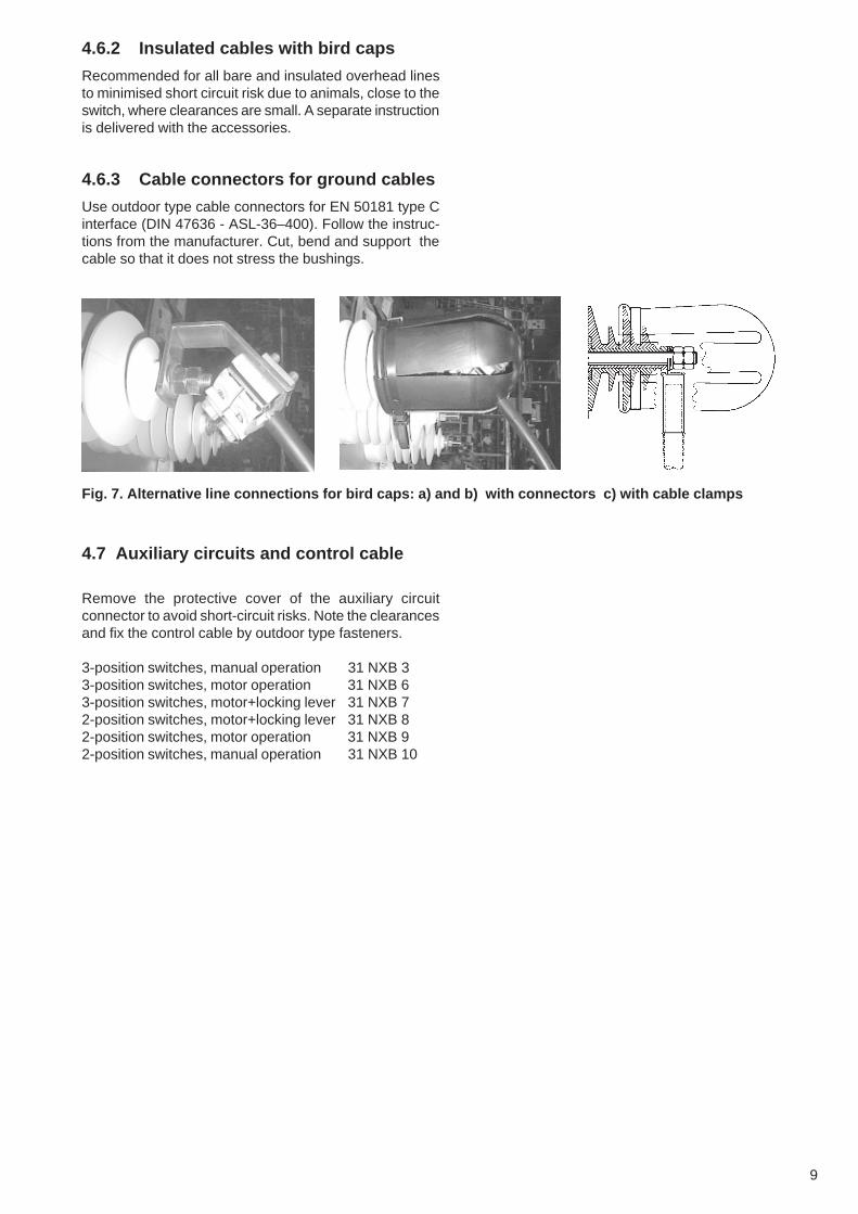
4.6.2 Insulated cables with bird caps
Recommended for all bare and insulated overhead linesto minimised short circuit risk due to animals, close to theswitch, where clearances are small. A separate instructionis delivered with the accessories.
4.6.3 Cable connectors for ground cables
Use outdoor type cable connectors for EN 50181 type Cinterface (DIN 47636 - ASL-36–400). Follow the instruc-tions from the manufacturer. Cut, bend and support thecable so that it does not stress the bushings.
Fig. 7. Alternative line connections for bird caps: a) and b) with connectors c) with cable clamps
4.7 Auxiliary circuits and control cable
Remove the protective cover of the auxiliary circuitconnector to avoid short-circuit risks. Note the clearancesand fix the control cable by outdoor type fasteners.
3-position switches, manual operation 31 NXB 33-position switches, motor operation 31 NXB 63-position switches, motor+locking lever 31 NXB 72-position switches, motor+locking lever 31 NXB 82-position switches, motor operation 31 NXB 92-position switches, manual operation 31 NXB 10

10
5. Earthings
5.1 Switch frame
The frame of the switch should always be earthed inaccordance with the local safety regulations. Noteespecially the minimum earthing conductor area, earthingresistance, corrosion protection, and mechanical protectionand insulation of the lower part. Both the disconnectingand earthing functions of the switch are ineffective ifthe frame is not earthed. In addition the line insulatorcrossarm shall be earthed, if the switch is mounted on aseparate crossarm.
The earthing cable with a crimp for an M12 bolt can beconnected to the tin plated earthing terminal at the end ofthe switch. Alternatively a terminal clamp type OJUZLL1for 16...63 mm2 copper wires or type OJUZLL 3 for16...70 mm2 aluminium wires can be ordered separately.
The switch can also be earthed by earthing the crossarmfor example with the earthing terminal NPTMS 8.
5.2 Integrated earthing switch
Ensure that the integrated earthing switch earths thecorrect side of the switch. The earthing switch on thedownstream side provides natural interlocking betweenthe main switch and earthing switch in a radial network.The earthing switch side can be identified from the earthingterminal, see the drawing below.
Fig. 8. Identification of the earthing switch side
The earthing direction should be marked clearly for theoperator for example by fixing this symbol under theswitch.
Fig. 9. The earthing direction symbol
I O
CLOSED OPEN
ON OFF EARTH ON
Main circuitdiagram
Alternative positionindicatorsymbols
Ear
thin
gsw
itch
side
Non
eart
hing
side
Earthing terminal
11
5.3 Auxiliary circuits
The auxiliary system may be different from case tocase. The earthing and protection of each specificsystem should be planned carefully for safety andprotection reasons. As a minimum the following generalrules should be followed:
All systems:* The shield of measuring and control cables shall
be earthed at both ends to protect the controlelectronics.
* The frames of all components of the pole mountedstation should be connected to the common earth(switch, VT, control equipment)
* The primary of any voltage transformer shall beconnected between two phases, not betweenphase and earth. The secondary shall be earthedto the frame or to the control cabinet earth.
Isolated or resonant earthed neutral systems:* The earth fault voltages should be limited to fulfil
local safety regulations concerning combinedearthing of low and high voltage systems. Theoperator should not be exposed to dangerous earthingvoltages and these voltages should not be conductedto low voltage circuits.
Earthed and low-ohm earthed neutral systems:* The earth fault voltages cannot normally be limited
to a safe level.* All components, connected to the high voltage earth,
(control cabinet, local I/O push buttons, possiblemanual operating elements) should be mounted sohigh, that they cannot be reached from conductiveearth level. An insulating ladder or platform shouldbe used.Alternatively an earth mat below the control boxmay be used to limit touch voltages. The risk ofpotential step voltages should be analyzed in thiscase. See the enclosed drawing 31NXB23.
* The auxiliary supply should be taken from a trans-former on the same pole, or other source, neutralconnected to the common earth (solar or windenergy). The pole mounted station should not beconnected to a public low voltage or telephonenetwork.
5.4 Surge arresters
The earthing cable should be as straight as possible andsteep curves should be avoided. Minimum area 16 mm2
Cu. The separate earthing cable should be connectedto the common earth below the control cabinet, If thesurge arresters are mounted on a separate cross arm.The separate cable is not necessary, if the surge arrestersare mounted and earthed on the switch frame.
6. EnergisingBefore energising the Sectos make sure that:
1. The gas pressure is checked via the gas densitymonitoring contact.
2. The functioning of operating devices and positionindicators is correct.
3. Ensure that the line section to be earthed by the3-position switch is correct and clearly marked forthe operator (5.2).
4. The line and earthing cables are connected and theclearances are sufficient.
5. The auxiliary circuits (if any) are connected.6. The lightning overvoltages are limited below the
withstand level of the Sectos.7. Ensure that conducting parts, which may be exposed
to dangerous earth fault voltages during faults, cannotbe touched from ground level.
7. MaintenanceSectos is maintenance free for the expected service lifeof the switch. The mechanism is protected by ahermetically sealed housing and no greasing is required.The mechanism housing should not be opened to avoidmoisture ingress and reassembling failures. If the housinghas to be opened, the desiccants and inhibitors shouldbe replaced with new ones.
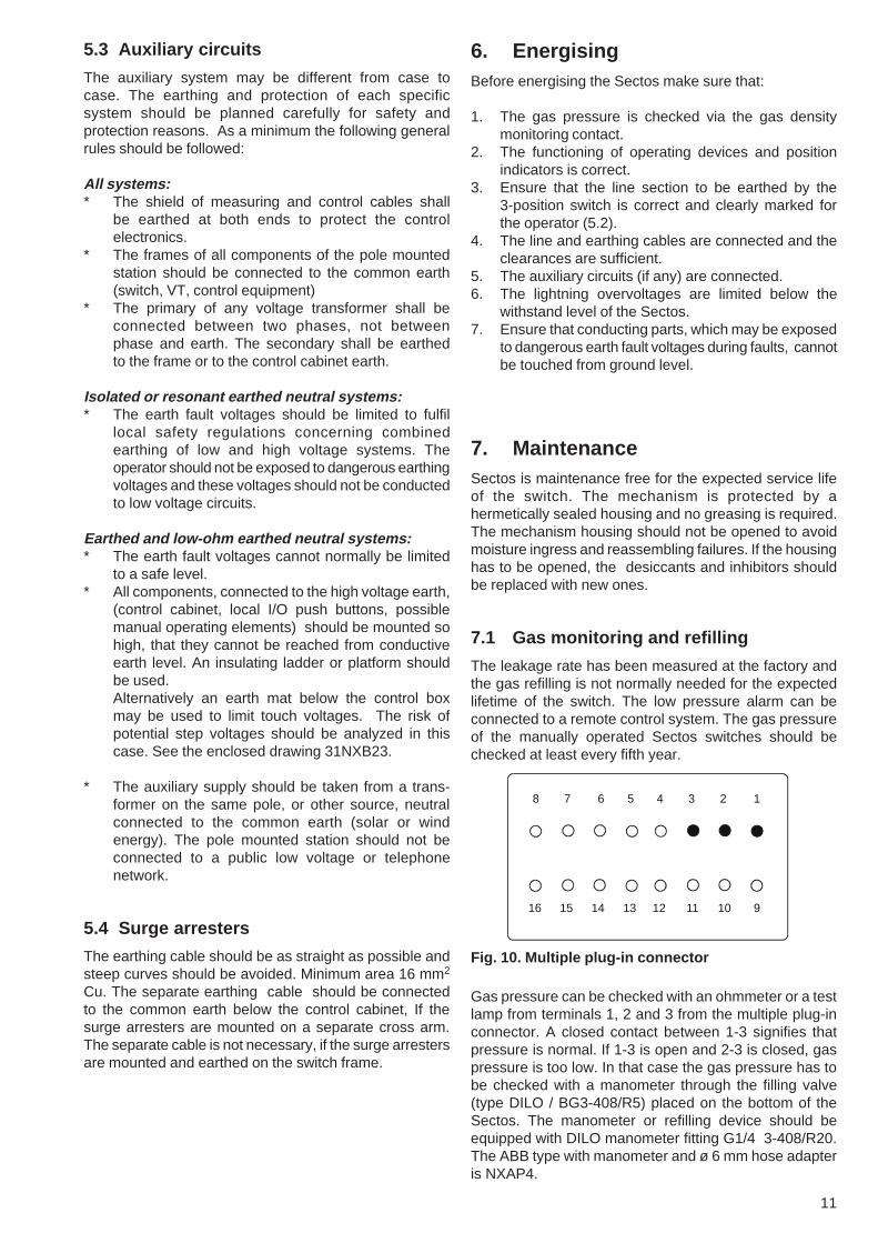
7.1 Gas monitoring and refilling
The leakage rate has been measured at the factory andthe gas refilling is not normally needed for the expectedlifetime of the switch. The low pressure alarm can beconnected to a remote control system. The gas pressureof the manually operated Sectos switches should bechecked at least every fifth year.
Fig. 10. Multiple plug-in connector
Gas pressure can be checked with an ohmmeter or a testlamp from terminals 1, 2 and 3 from the multiple plug-inconnector. A closed contact between 1-3 signifies thatpressure is normal. If 1-3 is open and 2-3 is closed, gaspressure is too low. In that case the gas pressure has tobe checked with a manometer through the filling valve(type DILO / BG3-408/R5) placed on the bottom of theSectos. The manometer or refilling device should beequipped with DILO manometer fitting G1/4 3-408/R20.The ABB type with manometer and ø 6 mm hose adapteris NXAP4.
8 7 6 5 4 3 2 1
16 15 14 13 12 11 10 9

12
8. Operation safety
8.1 Normal operation
Pole mounted Sectos switches are safe to operate evenin the most abnormal situations. However the operation isnot allowed if there is any doubt about the correct SF6pressure (chapter 7.1).
Follow the local safety instructions if you are going towork close to the line behind the switch. The commonrules are:
1. Open the switch and check the open position fromthe position indicator.
2. Prevent unintended closing following the local safetyregulations; for example by warning shields, optionallocking device, chains and padlock or manualoperating device with padlocking facility.
3. Ensure that the line is dead with an accepted voltagetesting device.
4. Connect the line to the earth using the integratedearthing switch or a portable equipment for earthing,IEC 1230 (1993). Ensure that the correct line sectionis earthed by the integrated earthing switch. Ensurethat the condition of the frame earthing circuit is goodby measuring the earthing resistance regularly.
5. The secondary of the optional CT must be short-circuited, if the secondary load is removed while theprimary line is live.
8.2 SF6 - gas
Pure SF6 -gas is a nontoxic, non-flammable, heavy inertinsulating cooling gas of high dielectric strength andthermal stability.
The Sectos uses SF6-gas as an insulation and arcquenching medium. Arcing in SF6 switchgear decomposesa small amount of the gas. Part of these decompositionproducts may be toxic. Under normal operating conditionsthese products are only present in small quantities and forlimited periods of time, within the switch enclosure beforethey are absorbed by a filter. During normal operation ofthe Sectos the operator does not need any specialprotection.
8.3 Recommended procedurefor disposal of the Sectos
Sectos includes valuable materials for recycling: stainlesssteel, copper, aluminium, steel, and SF6 -gas.
Small amounts of SF6 decomposition products may havebeen formed during the breaking operations. These arelargely eliminated by the absorbent inside the tank.However, some precautions are recommended to ensuresafe handling of these materials. Local regulations if anyshould be followed. The re-cycling/disposal can be sub-contracted to ABB or to a specialised company.Alternatively the user can follow the procedure below.
During the procedure, care should be taken to avoidcontact of decomposition powders and cleaning fluidswith skin or eyes. Compressed air should not be used forremoving powders.
1. SF6 -gas can be removed from the switch using avacuum pump and a compressor to transfer to bottlesuitable for this gas. When the gas is pumped offallow dry air flow into the evacuated tank. The gasmanufacturers are prepared to receive used SF6 -gas for recycling.
2. The tank should be cut open outdoors or in a wellventilated room. Cutting methods based to hightemperature ( > 500 °C) should not be used to awoidformation decomposition products.
The absorbent should be taken away to beneutralised. A suitable method is immersing in asolution of 1...3 kg sodium carbonate (Na2CO3) in100 l water for 24...48 hours. Contact with skin andeyes should be avoided, especially if higher con-centrations are used.
3. All other parts of the switch can be handled as normalmetallic or plastic waste. It is recommended that thepossible decomposition powder if any be removedusing a vacuum cleaner or by rinsing with cleanwater. The vacuum cleaner bags should beneutralised with same procedure as the absorbent.
For more information see IEC Technical Report 1634(1995): “High-voltage switchgear and controlgear – Useand handling of sulphur hexafluoride (SF6) in high-voltageswitchgear and controlgear”, Chapter 6.5: “Treatmentat end of life of SF6-filled equipment”.

13
9. Installation examplesThe Sectos can be installed in many ways on differenttypes of poles and steelwork. Some mounting examplesare shown on the following pages:
Fig. 10.1 NXB_ below a separate crossarm

14
Fig. 10.2 NXB_ below the line crossarm
15
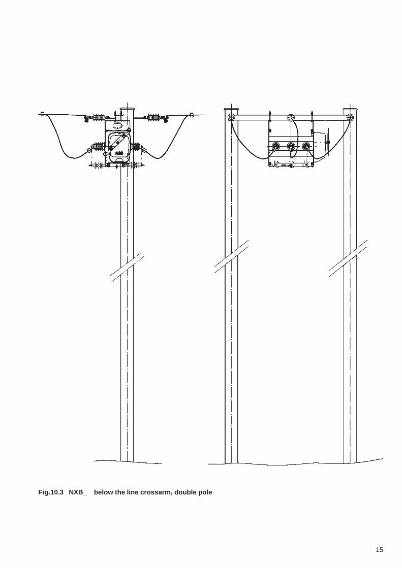
Fig.10.3 NXB_ below the line crossarm, double pole

16
Fig. 10.4 NXB_ above the line crossarm
17
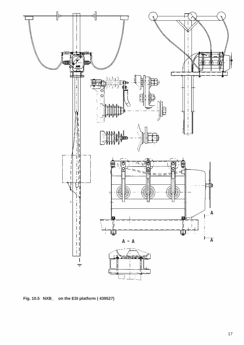
Fig. 10.5 NXB_ on the ESI platform ( 439527)

18
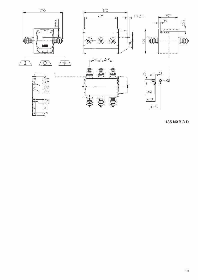
10. Dimension drawings
135 NXB 1 D
135 NXB 2 D
19
135 NXB 3 D

20
Mou
ntin
g N
XB
-sw
itch
disc
onne
ctor
on
the
ES
I pla
tform
usi
ng th
e br
acke
ts ty
peN
XB
M 1
0
34 N
XB
14
B
21
Mou
ntin
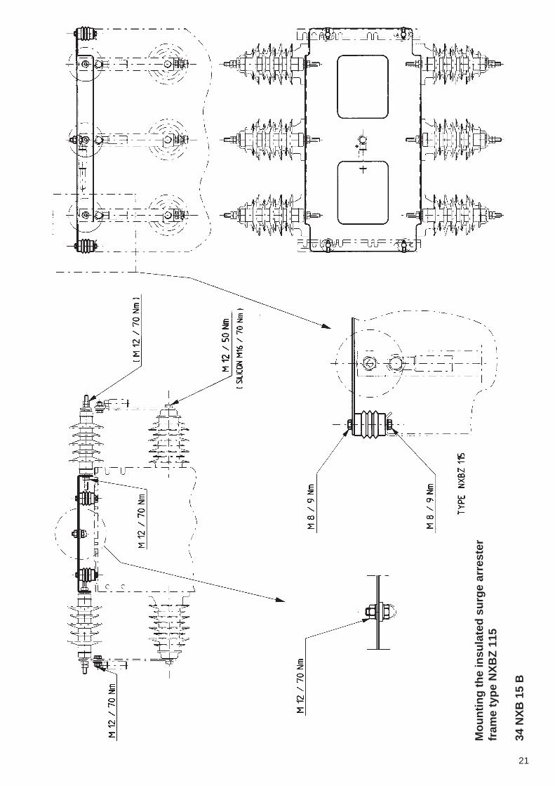
g th
e in
sula
ted
surg
e ar
rest
erfr
ame
type
NX
BZ
115
34 N
XB
15
B

22
Mou
ntin
g th
e su
rge
arre
ster
fram
ety
pe N
XB
Z 1
23
34 N
XB
18
B

23
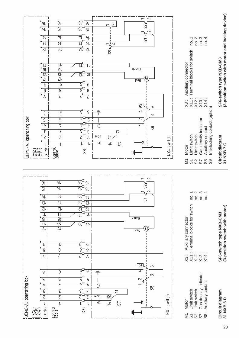
M1
Mot
orX
3 :
Aux
iliar
y co
nnec
tor
S1
Lim
it sw
itch
X11
:T
erm
inal
blo
cks
for
switc
hno
. 1S
2Li
mit
switc
hX
12 :
no. 2
S7
Gas
den
sity
indi
cato
rX
13 :
no. 3
S8
Aux
iliar
y co
ntac
tX
14 :
no. 4
Circ
uit d
iagr
amS
F6-
switc
h ty
pe N
XB
-CM
331
NX
B 6
D(3
-pos
ition
sw
itch
with
mot
or)
M1
Mot
orX
3 :
Aux
iliar
y co
nnec
tor
S1
Lim
it sw
itch
X11
:T
erm
inal
blo
cks
for
switc
hno
. 1S
2Li
mit
switc
hX
12 :
no. 2
S7
Gas
den
sity
indi
cato
rX
13 :
no. 3
S8
Aux
iliar
y co
ntac
tX
14 :
no. 4
S9
Inte
rlock
ing
cont
act (
optio
n)
Circ
uit d
iagr
amS
F6-
switc
h ty
pe N
XB
-CM
331
NX
B 7
C(3
-pos
ition
sw
itch
with
mot
or a
nd lo
ckin
g de
vice
)
23
M1
Mot
orX
3 :
Aux
iliar
y co
nnec
tor
S1
Lim
it sw
itch
X11
:T
erm
inal
blo
cks
for
switc
hno
. 1S
2Li
mit
switc
hX
12 :
no. 2
S7
Gas
den
sity
indi
cato
rX
13 :
no. 3
S8
Aux
iliar
y co
ntac
tX
14 :
no. 4
Circ
uit d
iagr
amS
F6-
switc
h ty
pe N
XB
-CM
331
NX
B 6
D(3
-pos
ition
sw
itch
with
mot
or)
M1
Mot
orX
3 :
Aux
iliar
y co
nnec
tor
S1
Lim
it sw
itch
X11
:T
erm
inal
blo
cks
for
switc
hno
. 1S
2Li
mit
switc
hX
12 :
no. 2
S7
Gas
den
sity
indi
cato
rX
13 :
no. 3
S8
Aux
iliar
y co
ntac
tX
14 :
no. 4
S9
Inte
rlock
ing
cont
act (
optio
n)
Circ
uit d
iagr
amS
F6-
switc
h ty
pe N
XB
-CM
331
NX
B 7
C(3
-pos
ition
sw
itch
with
mot
or a
nd lo
ckin
g de
vice
)

24
M1
Mot
orX
3 :
Aux
iliar
y co
nnec
tor
S1
Lim
it sw
itch
X11
:T
erm
inal
blo
cks
for
switc
hno
. 1S
2Li
mit
switc
hX
12 :
no. 2
S7
Gas
den
sity
indi
cato
rX
13 :
no. 3
S8
Aux
iliar
y co
ntac
tX
14 :
no. 4
S9
Inte
rlock
ing
cont
act (
optio
n)
Circ
uit d
iagr
amS
F6-
switc
h ty
pe N
XB
-AM
331
NX
B 8
C(2
-pos
ition
sw
itch
with
mot
or a
nd lo
ckin
g de
vice
)
M1
Mot
orX
3 :
Aux
iliar
y co
nnec
tor
S1
Lim
it sw
itch
X11
:T
erm
inal
blo
cks
for
switc
hno
. 1S
2Li
mit
switc
hX
12 :
no. 2
S7
Gas
den
sity
indi
cato
rX
13 :
no. 3
S8
Aux
iliar
y co
ntac
tX
14 :
no. 4
Circ
uit d
iagr
amS
F6-
switc
h ty
pe N
XB
-AM
331
NX
B 9
C(2
-pos
ition
sw
itch
with
mot
or)

25
S7
Gas
den
sity
indi
cato
rX
3 :
Aux
iliar
y co
nnec
tor
S8
Aux
iliar
y co
ntac
t
Circ
uit d
iagr
amS
F6-
switc
h ty
pe N
XB
-C3
31 N
XB
3 C
(3-p
ositi
on s
witc
h, m
anua
l ope
ratio
n)
S8
Aux
iliar
y co
ntac
tX
3 :
Aux
iliar
y co
nnec
tor
S7
Gas
den
sity
indi
cato
rX
11 :
Ter
min
al b
lock
s fo
r sw
itch
Circ
uit d
iagr
amS
F6-
switc
h ty
pe N
XB
-A3
31 N
XB
10
A(2
-pos
ition
sw
itch,
man
ual o
pera
tion)

26
Enclosure 1. Line connections
General
Copper connectors:
Note the conductor area fits the used connector andtighten by correct torque.
Aluminium connectors:
Ensure that the conductor area and material fits the usedconnector. The solid aluminium bar shall be left in theempty slot, if a double slot connector ( type KG_) is usedfor a single conductor. The oxidized surface of theconductor end and the grooved bottom of the connectorshall be removed by a steel brush and the surfacesgreased immediately by a special grease for aluminiumconnections to prevent reoxidation. The slots of theconnectors are greased by the manufacturer. Tighten bycorrect torque.Recommended greases: ENSTO type SR1, ABB DSAX-RK, PENETROX-A.
Note!The aluminium oxide layer increases contact resistanceand may cause dangerous overheating.
Combined connectors for aluminium andcopper:
Note which slot is for copper; tin plated copper bars areforced in the other slot for copper conductors. Follow thepreceeding instructions depending on the conductor type.Leave the solid aluminium bar in the aluminium slot, ifonly copper conductor is connected.
Aluminium cable clamps:
Cable clamps may be connected direct on the bushingsor on the optional terminal bar.Ensure that the conductor area and material fits the usedclamp. Brush the conductor end. The conductor hole isfilled with grease, which also protects the connector, ifimmediately inserted. Compress according to theinstructions of the tool manufacturer starting from thecable end. It is not necessary to brush the tin plated cablelugs. The large washer is used to stabilize stresses andthe spring washer compensates dimension variations dueto temperature changes and creepage.
Copper cable clamps:
Follow the instructions of aluminium clamps. The brushingand greasing is not necessary.
27
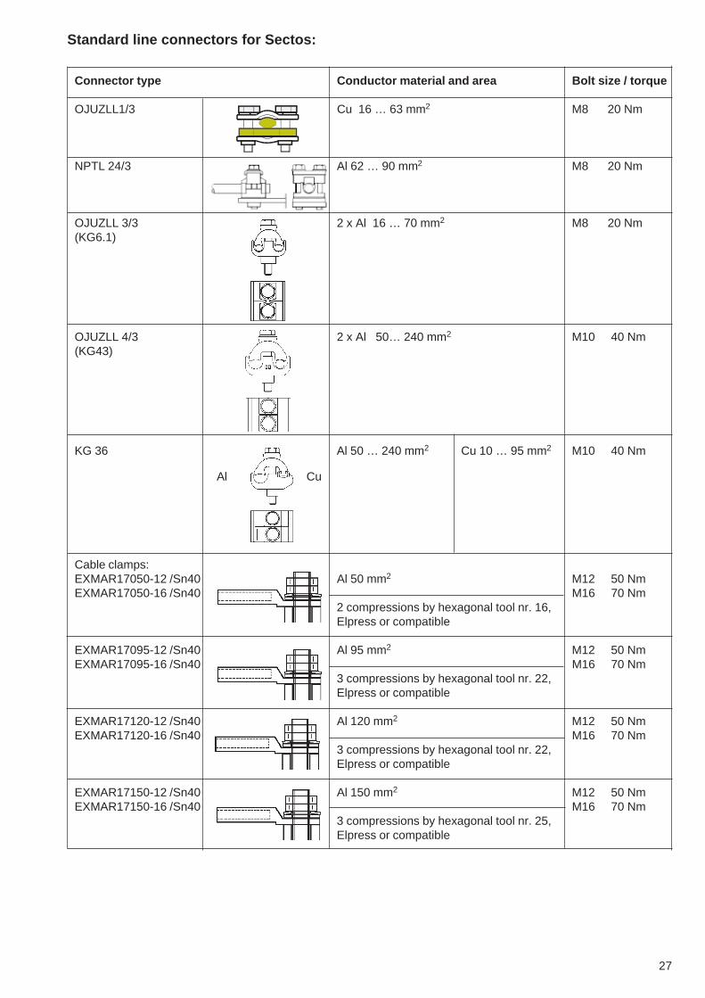
Standard line connectors for Sectos:
Connector type Conductor material and area Bolt size / torque
OJUZLL1/3 Cu 16 … 63 mm2 M8 20 Nm
NPTL 24/3 Al 62 … 90 mm2 M8 20 Nm
OJUZLL 3/3 2 x Al 16 … 70 mm2 M8 20 Nm(KG6.1)
OJUZLL 4/3 2 x Al 50… 240 mm2 M10 40 Nm(KG43)
KG 36 Al 50 … 240 mm2 Cu 10 … 95 mm2 M10 40 Nm
Cable clamps:EXMAR17050-12 /Sn40 Al 50 mm2 M12 50 NmEXMAR17050-16 /Sn40 M16 70 Nm
2 compressions by hexagonal tool nr. 16,Elpress or compatible
EXMAR17095-12 /Sn40 Al 95 mm2 M12 50 NmEXMAR17095-16 /Sn40 M16 70 Nm
3 compressions by hexagonal tool nr. 22,Elpress or compatible
EXMAR17120-12 /Sn40 Al 120 mm2 M12 50 NmEXMAR17120-16 /Sn40 M16 70 Nm
3 compressions by hexagonal tool nr. 22,Elpress or compatible
EXMAR17150-12 /Sn40 Al 150 mm2 M12 50 NmEXMAR17150-16 /Sn40 M16 70 Nm
3 compressions by hexagonal tool nr. 25,Elpress or compatible
Al Cu
28
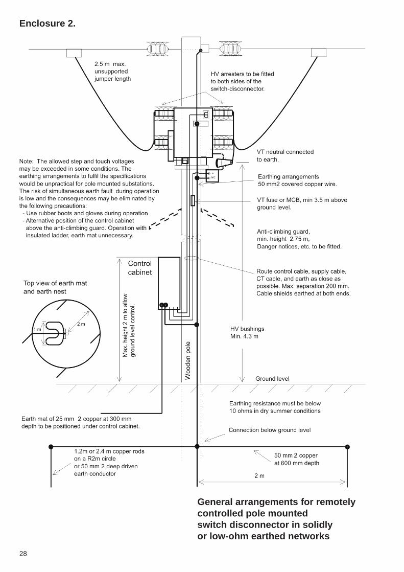
Enclosure 2.
General arrangements for remotelycontrolled pole mountedswitch disconnector in solidlyor low-ohm earthed networks

Mul
tiprin
t50
0, 0
209
34 N
XB
2 A
02-
09
ABB OyMedium Voltage TechnologyP.O.Box 613, FIN-65101 Vaasa, FinlandTel: +358 10 22 11Fax: +358 10 22 44661www.abb.com/mediumvoltage
Information given in this publicationis generally applicable to equipmentdescribed.Changes may be made in future withoutnotice.