Specifications Information and Repair Parts Manual 4851-97 & 4861-97 4861-250-00 1 6/2016 Please read and save this Repair Parts Manual. Read this manual and the General Operating Instructions carefully before attempting to assemble, install, operate or maintain the product described. Protect yourself and others by observing all safety information. The Safety Instructions are contained in the General Operating Instructions. Failure to comply with the safety instructions accompanying this product could result in personal injury and/or property damage! Retain instructions for future reference. AMT reserves the right to discontinue any model or change specifications at any time without incurring any obligation. ©2016 AMT Pump Company, A Subsidiary of The Gorman-Rupp Company, All Rights Reserved. Periodic maintenance and inspection is required on all pumps to ensure proper operation. Unit must be clear of debris and sediment. Inspect for leaks and loose bolts. Failure to do so voids warranty. 3/4-Inch Bronze Centrifugal Pump Refer to pump manual 1808-634-00 for General Operating and Safety Instructions. GENERAL SAFETY INFORMATION (FOR 12 VDC UNITS ONLY) 1. General connection information to a 12 VDC battery: a. Connect POSITIVE or PLUS(+) lead from the pump to battery first. POSITIVE lead of pump is red. b. Connect NEGATIVE or MINUS(-) lead last. NEGATIVE lead of pump is black. c. When DISCONNECTING – Disconnect NEGATIVE (-) lead first, then disconnect the POSITIVE (+) lead from the battery. 2. Specific connection information: a. If pump is installed in car or truck and the installed car or truck battery is being used: (1) Connect POSITIVE or PLUS (+) lead from the pump to battery first. POSITIVE lead of pump is red. (2) Then connect NEGATIVE or MINUS (-) lead to a ground away from the battery, such as the metal of the car. Always connect NEGATIVE (-) last. NEGATIVE lead of pump is black. (3) When DISCONNECTING – Disconnect the NEGATIVE (-) lead from the grounded location, then disconnect the POSITIVE (+) lead from the battery. b. Pump is installed in recreational vehicle (RV), boat, motor home, etc. (1) Follow general connection information. (2) If possible, connect NEGATIVE (-) lead of the pump to negative wiring terminal strip or other negative common point of the battery (away from the battery) if so equipped. 3. When attaching pump leads to battery terminals, be sure that the area (bilge of a boat, for instance) is adequately ventilated to prevent an explosion or fire from explosive or flammable vapors that may be present. Batteries emit hydrogen gas which is explosive. Avoid smoking, sparks or open flame anywhere in the vicinity of the battery. Explosion from battery can cause blindness. Shield eyes when working near any battery. Batteries contain sulfuric acid. In case of contact with eyes, skin or clothing, flush immediately with large amount of water, get medical attention. 4. When using leads longer than those supplied, be sure the wire is adequately sized. Do not add acid or electrolyte to battery being used – add only water. Consult the battery manufacturers for any additional safety instructions. INSTALLATION (FOR 12 VDC UNITS ONLY) WIRING & ROTATION Connect black wire to NEGATIVE (-) terminal of battery. The orange wire with the fuse holder should run to an overload protected switch or circuit breaker, with a wire from switch or breaker to POSITIVE (+) terminal of battery. Electrical circuit must be independent of all other accessories. To prolong motor life, install pump so normal motor rotation is clockwise (See Figure 1). Use proper wire size as determined by Wire Table (See Figure 1). The proper fuse has been included in the fuse holder. Should this fuse blow, replace with the same size fuse after determining reason for blown fuse. NOTE: No warranty consideration will be given to pumps that are returned without the properly sized fuse and fuse holder supplied with the pump. DESCRIPTION This compact utility pump is designed for a wide range of dewatering and liquid transfer applications including marine and aquaculture. Handles liquids from 40° F to 180° F (4º to 82º C). This is a manual unit, no controls are supplied. For use with nonflammable, non-abrasive liquids compatible with pump component ma- terials. These pumps self-prime (to 4-1/2 ft. lift with pump filled) and can be used as a bilge pump for small boats or a water system pump in campers and trailers. The pump can be mounted up to a 45° angle or on a thru-hull fitting and seacock for applications requiring water aboard to be pumped overboard. Connection Length Between Battery and Motor 12V 1-10ft 12 gauge wire 11-20 10 gauge wire 21-30 8 gauge wire If unsure about the above information or the wiring diagrams, consult an electrician familiar with motor wiring. AMP DRAW AND FUSE SIZES (FOR 12VDC UNITS ONLY) AMP draw (approx.) 10.5 Fuse size 15 Figure 1 – Wiring Diagram

Welcome message from author
This document is posted to help you gain knowledge. Please leave a comment to let me know what you think about it! Share it to your friends and learn new things together.
Transcript
Specifications Information and Repair Parts Manual 4851-97 & 4861-97
4861-250-00 1 6/2016
Please read and save this Repair Parts Manual. Read this manual and the General Operating Instructions carefully before attempting to assemble, install, operate or maintain the product described. Protect yourself and others by observing all safety information. The Safety Instructions are contained in the General Operating Instructions. Failure to comply with the safety instructions accompanying this product could result in personal injury and/or property damage! Retain instructions for future reference. AMT reserves the right to discontinue any model or change specifications at any time without incurring any obligation.
©2016 AMT Pump Company, A Subsidiary of The Gorman-Rupp Company, All Rights Reserved.
Periodic maintenance and inspection is required on all pumps to ensure proper operation. Unit must be clear of debris and sediment. Inspect for leaks and loose bolts. Failure to do so voids warranty.
3/4-Inch Bronze Centrifugal PumpRefer to pump manual 1808-634-00 for General Operating and Safety Instructions.
GENERAL SAFETY INFORMATION(FOR 12 VDC UNITS ONLY)
1. General connection information to a 12 VDC battery:a. Connect POSITIVE or PLUS(+) lead from the pump to battery first.
POSITIVE lead of pump is red.b. Connect NEGATIVE or MINUS(-) lead last. NEGATIVE lead of pump
is black.c. When DISCONNECTING – Disconnect NEGATIVE (-) lead first,
then disconnect the POSITIVE (+) lead from the battery.2. Specific connection information:
a. If pump is installed in car or truck and the installed car or truck battery is being used:
(1) Connect POSITIVE or PLUS (+) lead from the pump to battery first. POSITIVE lead of pump is red.
(2) Then connect NEGATIVE or MINUS (-) lead to a ground away from the battery, such as the metal of the car. Always connect NEGATIVE (-) last. NEGATIVE lead of pump is black.
(3) When DISCONNECTING – Disconnect the NEGATIVE (-) lead from the grounded location, then disconnect the POSITIVE (+) lead from the battery.
b. Pump is installed in recreational vehicle (RV), boat, motor home, etc.(1) Follow general connection information.(2) If possible, connect NEGATIVE (-) lead of the pump to negative
wiring terminal strip or other negative common point of the battery (away from the battery) if so equipped.
3. When attaching pump leads to battery terminals, be sure that the area (bilge of a boat, for instance) is adequately ventilated to prevent an explosion or fire from explosive or flammable vapors that may be present.
Batteries emit hydrogen gas which is explosive. Avoid smoking, sparks or open flame anywhere in the vicinity of the battery.Explosion from battery can cause blindness. Shield eyes when working near any battery.Batteries contain sulfuric acid. In case of contact with eyes, skin or clothing, flush immediately with large amount of water, get medical attention.4. When using leads longer than those supplied, be sure the wire is
adequately sized.
Do not add acid or electrolyte to battery being used – add only water. Consult the battery manufacturers for any additional safety instructions.
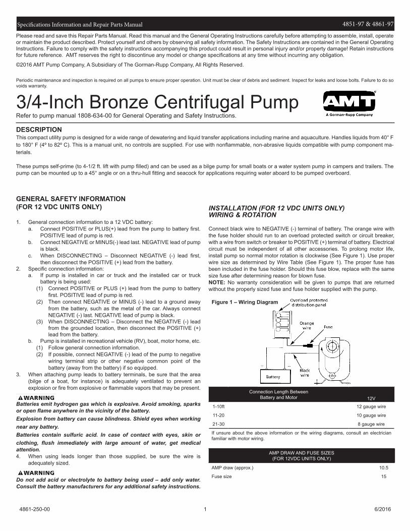
INSTALLATION (FOR 12 VDC UNITS ONLY)WIRING & ROTATION
Connect black wire to NEGATIVE (-) terminal of battery. The orange wire with the fuse holder should run to an overload protected switch or circuit breaker, with a wire from switch or breaker to POSITIVE (+) terminal of battery. Electrical circuit must be independent of all other accessories. To prolong motor life, install pump so normal motor rotation is clockwise (See Figure 1). Use proper wire size as determined by Wire Table (See Figure 1). The proper fuse has been included in the fuse holder. Should this fuse blow, replace with the same size fuse after determining reason for blown fuse. NOTE: No warranty consideration will be given to pumps that are returned without the properly sized fuse and fuse holder supplied with the pump.
DESCRIPTIONThis compact utility pump is designed for a wide range of dewatering and liquid transfer applications including marine and aquaculture. Handles liquids from 40° Fto 180° F (4º to 82º C). This is a manual unit, no controls are supplied. For use with nonflammable, non-abrasive liquids compatible with pump component ma-terials.
These pumps self-prime (to 4-1/2 ft. lift with pump filled) and can be used as a bilge pump for small boats or a water system pump in campers and trailers. The pump can be mounted up to a 45° angle or on a thru-hull fitting and seacock for applications requiring water aboard to be pumped overboard.
Connection Length Between Battery and Motor 12V
1-10ft 12 gauge wire
11-20 10 gauge wire
21-30 8 gauge wire
If unsure about the above information or the wiring diagrams, consult an electrician familiar with motor wiring.
AMP DRAW AND FUSE SIZES(FOR 12VDC UNITS ONLY)
AMP draw (approx.) 10.5
Fuse size 15
Figure 1 – Wiring Diagram

Specifications Information and Repair Parts Manual 4851-97 & 4861-97
4861-250-00 2 6/2016
MAINTENANCE
Disconnect from power source before servicing or inspecting pump for any reason. Failure to do so could result in fatal electrical shock!
MECHANICAL SEAL REPLACEMENTRefer to Figures 2, and 3
IMPORTANT: Always replace both seal seat (Ref. No. 7) and seal head (Ref. No. 6) to ensure proper matching of components!1. Unthread fasteners (Ref. No. 8), remove casing (Ref. No. 12) and casing
seal (Ref. No. 11).2. Unscrew fastener (Ref. No. 10) from impeller (Ref. No. 9) and remove
impeller.3. Remove fasteners (Ref. No. 2) and washers (Ref. No. 3) and remove
adapter (Ref. No. 5).4. Lay adapter face down on a flat stable surface and press seal head from
adapter.5. Pry seal seat from rear of impeller with a screwdriver or other suitable
means.6. Clean recess in adapter for seal head and recess in impeller for seal seat
before inserting any new parts.7. Inspect polished face of seal seat and head to besure each piece is clean
and not marred.8. Press new head into recess in adapter. A sealing compound (such as
silicon or Permatex) may be used to assure a water tight fit on outside of head.
9. Press seal seat squarely into cavity in impeller (See Figure 2). If seal seat does not press squarely into cavity, it can be adjusted in place by pushing on it with a piece of pipe. Always use a piece of cardboard between pipe and seal seat to avoid scratching face of seal seat. This is a lapped surface and must be handled very carefully.
10. After seal seat is in place, check that it is clean and has not been scratched or cracked.
11. Mount adapter on motor mounting face.12. Replace impeller providing 0.020” clearance between adapter and
impeller (see figure 2), then tighten impeller fastener.13. Place casing seal on adapter and replace casing. Replace and tighten
fasteners.14. Before operating make certain impeller turns freely and is not rubbing
casing.
3/4-Inch Bronze Centrifugal Pump
Figure 2

Specifications Information and Repair Parts Manual 4851-97 & 4861-97
4861-250-00 3 6/2016
For Repair Parts contact dealer where pump was purchased.Please provide following information:-Model Number-Serial Number (if any)
Part description and number as shown in parts list
Figure 3 - Repair Parts Illustrations
3/4-Inch Bronze Centrifugal Pump

Specifications Information and Repair Parts Manual 4851-97 & 4861-97
4861-250-00 4 6/2016
Ref Part Number for ModelsNo. Description 4851-97 4861-97 Qty
1 Motor 1626-023-00 1626-023-00 1 2 Fastener Incl.w/ Ref 5 Incl.w/ Ref 5 2 3 Washer Incl.w/ Ref 5 Incl.w/ Ref 5 2 4 Flinger Washer Incl.w/ Ref KIT Incl.w/ Ref KIT 15 Adapter Kit 4861-030-97 4861-030-97 1
(includes Ref. Nos. 2, 3 and 5)6 & 7 Shaft Seal Assembly - Buna-N 1641-051-90 1641-051-90 1
8 Fastener Incl.w/ Ref 12 Incl.w/ Ref 12 4 9 Impeller Kit 4861-010-97 4861-010-97 1
(includes Ref. Nos. 9 and 10)10 Fastener Incl.w/ Ref 9 Incl.w/ Ref 9 1 11 Casing seal, Buna-N Incl.w/ Ref KIT Incl.w/ Ref KIT 1 12 Casing Kit 4850-001-97 4860-001-97 1
(includes Ref. Nos. 8, 12 and 13)13 Pipe plug Incl.w/ Ref 12 Incl.w/ Ref 12 1 KIT Gasket Kit 4850-300-90 4850-300-90 1
(includes Ref. Nos. 4 and 11)
Repair Parts List

Specifications Information and Repair Parts Manual 4851-97 & 4861-97
4861-250-00 5 6/2016
NOTES:

Specifications Information and Repair Parts Manual 4851-97 & 4861-97
4861-250-00 6 6/2016
NOTES:


www.amtpump.com
Related Documents