Job No.- 505335 TURNKEY TENDER DOCUMENT FOR DESIGN, SUPPLY, ERECTION & COMMISSIONING OF 33 kV/6.6 kV AND 33 kV/3.3 kV SUBSTATIONS BALANCE WORK AT DIPKA OPEN CAST PROJECT SOUTH EASTERN COALFIELDS LIMITED (DIPKA AREA) (SEP , 2017) VOLUME - II TECHNICAL CENTRAL MINE PLANNING AND DESIGN INSTITUTE REGIONAL INSTITUTE - V BILASPUR (C.G.) -495006

Welcome message from author
This document is posted to help you gain knowledge. Please leave a comment to let me know what you think about it! Share it to your friends and learn new things together.
Transcript
Job No.- 505335
TURNKEY TENDER DOCUMENT
FOR
DESIGN, SUPPLY, ERECTION & COMMISSIONING
OF
33 kV/6.6 kV AND 33 kV/3.3 kV SUBSTATIONS
BALANCE WORK
AT
DIPKA OPEN CAST PROJECT
SOUTH EASTERN COALFIELDS LIMITED (DIPKA AREA)
(SEP , 2017)
VOLUME - II
TECHNICAL
CENTRAL MINE PLANNING AND DESIGN INSTITUTE
REGIONAL INSTITUTE - V
BILASPUR (C.G.) -495006
NIT for 33/6.6 kV and 33/3.3 kV Substations
at Dipka OCP
RI-V,cmpdi Job No.- 505335 Volume- 2
INDEX
PARA
NO.
PARTICULARS PAGE NO.
2.1.0 INTRODUCTION 1 - 2
2.2.0 SYSTEM DESCRIPTION 3 - 24
2.3.0 SCOPE OF WORK 25-36
2.4.0 TECHNICAL SPECIFICATIONS OF EQUIPMENT 37-140
2.4.1 SPECIFICATION OF ISOLATOR 37 - 40
2.4.2 SPECIFICATION OF 33 kV LIGHTINING ARRESTER 41 - 42
2.4.3 SPECIFICATIONS OF CURRENT TRANSFORMER 43 - 44
2.4.4 SPECIFICATIONS OF POTENTIAL TRANSFORMER 45 - 46
2.4.5 SPECIFICATIONS OF VACUUM CIRCUIT BREAKER 47 - 61
2.4.6 SPECIFICATION OF 33/3.4 kV AND 33/6.6 kV TRANSFORMERS 62 - 80
2.4.7 SPECIFICATION FOR NEUTRAL GROUNDING RESISTER (NGR) 81 - 82
2.4.8 SPECIFICATION FOR CAPACITOR BANK 83 - 84
2.4.9 SPECIFICATIONS OF 3300/6600 VOLT SWITCHBOARD 85 - 90
2.4.10 SPECIFICATION OF CONTROL AND RELAY PANEL 91 – 93
2.4.11 SPECIFICATION OF STATION TRANSFORMER 94 - 96
2.4.12 SPECIFICATION OF AC POWER DISTRIBUTION BOARDS 97 - 100
2.4.13 SPECIFICATION FOR LIGHTING DISTRIBUTION BOARDS 101 - 102
2.4.14 SPECIFICATION FOR 110 V DC SUPPLY ARRANGEMENT 103 - 108
2.4.15 SPECIFICATION OF POWER,LIGHTING, CONTROL AND SPECIAL
CABLES
109 - 117
2.4.16 SPECIFICATION FOR LIGHTING MAST 118 - 119
2.4.17 SPECIFICATION OF POST/ DISC INSULATORS 120 - 123
2.4.18 SPECIFICATION OF FIRE FIGHTING EQUIPMENT 124- 138
2.4.19 SPECIFICATION OF LED ILLUMINATION 139-143
2.5.0 CIVIL AND STRUCTURALO WORKS 144-158
NIT for 33/6.6 kV and 33/3.3 kV Substations
at Dipka OCP
RI-V,cmpdi Job No.- 505335 Volume- 2
LIST OF DRAWINGS
1. Single Line Power Distribution Diagram of S/S No. 1 (2x5 MVA, 33/3.3 kV) - PLATE No. 1
2. Single Line Power Distribution Diagram of S/S No.2&3 (2x16 MVA, 33/6.6 kV) PLATE No. 2
3. Out Door Yard, Cable Trench , Shield Wire & S/S Building (Common for all Substations) -
PLATE No. 3
4. Substation / Control Room Building (Common for all Substations) - PLATE No. 4
Introduction NIT for 33/6.6 kV and 33/3.3 kV substations
at Dipka OCP
RI-V, cmpdi Job No. 505335 Volume-2- Page No-1
2.1.0.0 INTRODUCTION
2.1.1.0 PREAMBLE
2.1.1.1 It is proposed to construct on turnkey basis the balance work of three numbers
substations at Dipka Opencast Project of SECL. The Capacity of the above
substations is as follows:
Substation No. 1 -- 2 x 5 MVA, 33/3.3 kV
Substation No. 2 & 3 (on Eastern & Western
sides of the quarry) -- 2 x 16 MVA, 33/6.6 kV each
Some of the equipment have already been supplied and part of civil works substation
wise have been completed earlier. The details of substation wise supplied items and
level of substation wise civil works completed have been elaborated in the tender
document.
All the three substations of Dipka Open Cast Project shall receive power individually
through two numbers of 33 kV overhead transmission lines (with AAAC,Panther
equivalent conductor) from the 2x30/36 MVA, 132/33 kV substation (already
constructed) near Dipka Area office. The work of drawing of 33 kV overhead lines
from 132/33 kV substation is not in the scope of this work. These substations shall
consist of Isolators, Lightning arresters, Current transformers, Potential transformers,
Vacuum Circuit Breakers, Main transformers, Control units, Lighting transformer,
Station transformer, Power and Lighting Distribution boards, DC power supply,
Capacitor banks, Cables, Fire extinguishers, Hydrant system of Fire fighting
including High Velocity Water Spraying for Power Transformers (HVWSS), Fire
detection, alarm and protection system for substation building and pump house,
Diesel Generator with shed, Earthing system, Safety equipment, Lighting system,
Lightning protection system, Substation building, Outdoor yard, underground sump
for fire fighting, bore hole with submersible pump, two pole structures for outward
6.6/3.3kV overhead transmission lines, Cable trenches, Testing equipment, Tools and
tackles,spares etc.
2.1.1.2 Necessary technical parameters have been given in the subsequent clauses of this
document for design of the substations. Tenderers /Bidders are required to carry out
checks and ensure guaranteed performance of the substations.
2.1.1.3 Tenderers /Bidders are requested to get themselves acquainted with the various
provisions of this document before submitting their offers. Tenderers may visit the
site at their own cost to have the details of site condition along with level of civil
works so far done by earlier contractor.
2.1.1.4 The scope of work shall be read along with Basic data, Plant description, Scope of
supply of balance equipment, Specifications of the equipment/items, balance Civil
and structural works etc. which are elaborated in subsequent clauses.
Introduction NIT for 33/6.6 kV and 33/3.3 kV substations
at Dipka OCP
RI-V, cmpdi Job No. 505335 Volume-2- Page No-2
2.1.2.0 LOCATION AND COMMUNICATION
2.1.2.1 Dipka opencast expansion project of South Eastern Coalfields forms part of Korba
Coalfields. The project is located in the Korba District of Chhattisgarh State.
2.1.2.2 Dipka Opencast project is at a distance of approximately 15 Km. from Gevra Road
Railway Station and 25 Km from Korba Railway Station. This station is on the branch
line of Champa and Gevra Road Railway station. The Gevra Road Railway Station is
about 93 km from Bilaspur and 708 km from Howrah by rail. A railway line exists
between Gevra Road Railway station and Gevra OCP, which has been extended up to
Dipka OCP.
2.1.2.3 The project is well connected by all weather Road. Dipka OCP is about 85 km from
Bilaspur, the Head quarters of SECL and is about 30 km from Korba.
2.1.3.0 PHYSIOGRAPHY
2.1.3.1 The general topography of the Dipka Opencast Project is gently undulating with
elevations ranging from 298 m to 326 m above mean sea level. The Drainage is
mainly by Lilagarh River which marks the South- Western boundary of the block.
Highest flood level of Lilagarh River as recorded in September 1988 near the quarry
boundary is 301.10 m on down stream side and 309.54 m on the upstream side from
mean sea level.
2.1.4.0 CLIMATIC CONDITIONS
2.1.4.1 The climate of the area is dry to moist tropical with well defined summer from April
to June, rainy season from July to September and winter season from October to
March.
2.1.4.2 The average annual rainfall is about 1265 mm as per RPR. The highest rainfall
recorded within a period of 24 hours over the last 35 years is 252.22 mm in
September, 1973.
2.1.4.3 The relative humidity varies from 70 to 100% during monsoon and 17 to 78% during
summer.
2.1.4.4 The ambient temperature rises to maximum of 50 degrees centigrade in summer and
drops to minimum of about 4 degrees centigrade in winter.
2.1.4.5 The wind direction is generally westerly to south westerly with wind velocity varying
from 0.57 to 9.3 km/h.
2.1.5.0 LOCATION OF SUBSTATIONS
2.1.5.1 The location of substations have been finalized and the tenderer may visit the
substation site prior to bidding.
System Description NIT for 33/6.6 kV and 33/3.3 kV substations
at Dipka OCP
RI-V, cmpdi Job No 505335 Volume-2- Page No-3
2.2.0.0 SYSTEM DESCRIPTION
2.2.1.0 Details of the Substations
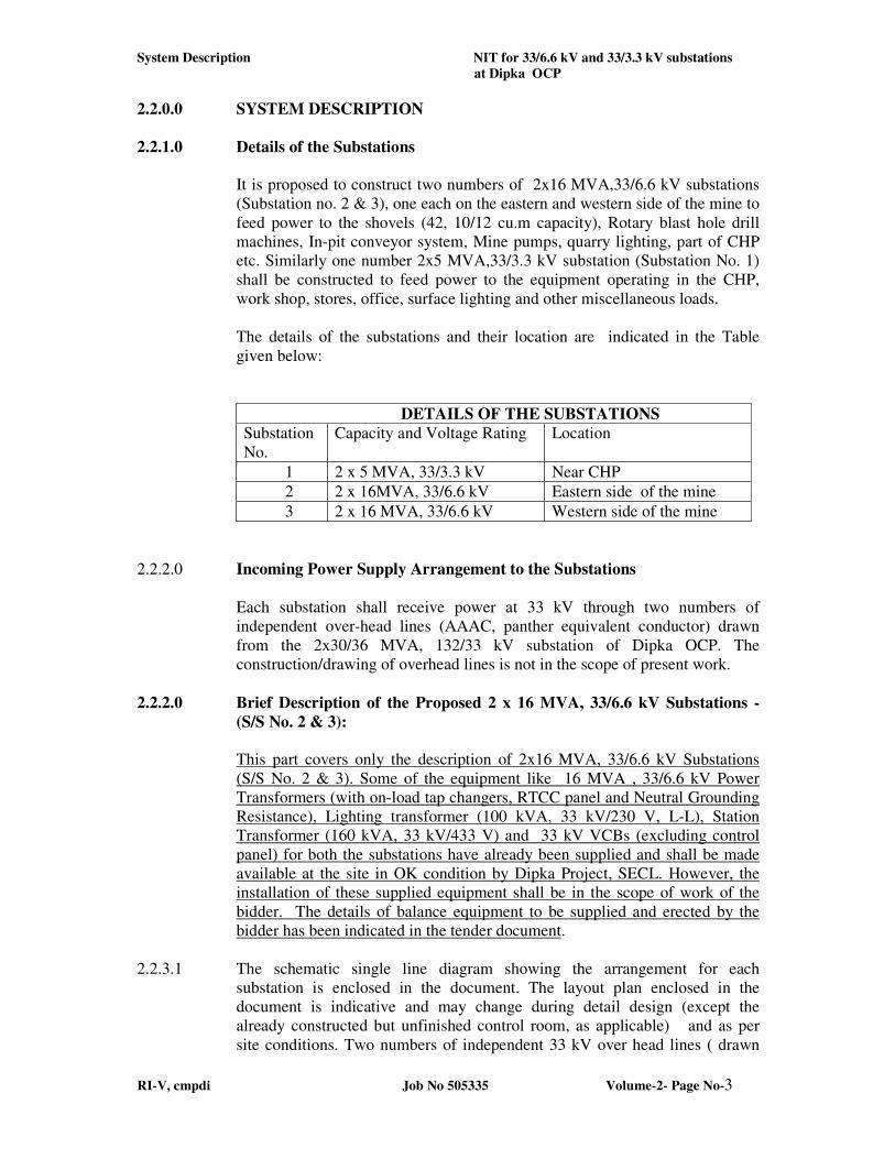
It is proposed to construct two numbers of 2x16 MVA,33/6.6 kV substations
(Substation no. 2 & 3), one each on the eastern and western side of the mine to
feed power to the shovels (42, 10/12 cu.m capacity), Rotary blast hole drill
machines, In-pit conveyor system, Mine pumps, quarry lighting, part of CHP
etc. Similarly one number 2x5 MVA,33/3.3 kV substation (Substation No. 1)
shall be constructed to feed power to the equipment operating in the CHP,
work shop, stores, office, surface lighting and other miscellaneous loads.
The details of the substations and their location are indicated in the Table
given below:
DETAILS OF THE SUBSTATIONS
Substation
No.
Capacity and Voltage Rating Location
1 2 x 5 MVA, 33/3.3 kV Near CHP
2 2 x 16MVA, 33/6.6 kV Eastern side of the mine
3 2 x 16 MVA, 33/6.6 kV Western side of the mine
2.2.2.0 Incoming Power Supply Arrangement to the Substations
Each substation shall receive power at 33 kV through two numbers of
independent over-head lines (AAAC, panther equivalent conductor) drawn
from the 2x30/36 MVA, 132/33 kV substation of Dipka OCP. The
construction/drawing of overhead lines is not in the scope of present work.
2.2.2.0 Brief Description of the Proposed 2 x 16 MVA, 33/6.6 kV Substations -
(S/S No. 2 & 3):
This part covers only the description of 2x16 MVA, 33/6.6 kV Substations
(S/S No. 2 & 3). Some of the equipment like 16 MVA , 33/6.6 kV Power
Transformers (with on-load tap changers, RTCC panel and Neutral Grounding
Resistance), Lighting transformer (100 kVA, 33 kV/230 V, L-L), Station
Transformer (160 kVA, 33 kV/433 V) and 33 kV VCBs (excluding control
panel) for both the substations have already been supplied and shall be made
available at the site in OK condition by Dipka Project, SECL. However, the
installation of these supplied equipment shall be in the scope of work of the
bidder. The details of balance equipment to be supplied and erected by the
bidder has been indicated in the tender document.
2.2.3.1 The schematic single line diagram showing the arrangement for each
substation is enclosed in the document. The layout plan enclosed in the
document is indicative and may change during detail design (except the
already constructed but unfinished control room, as applicable) and as per
site conditions. Two numbers of independent 33 kV over head lines ( drawn
System Description NIT for 33/6.6 kV and 33/3.3 kV substations
at Dipka OCP
RI-V, cmpdi Job No 505335 Volume-2- Page No-4
from 132/33 kV substation) shall feed power to the sectionalized over head
strung bus through pole mounted isolators, current transformer, potential
transformer and vacuum circuit breakers. Proper anti climbing device shall be
provided on the poles on which incoming 33 kV lines are terminated. The
incoming isolators shall be provided with earthing switches and station class
lightning arrestors. Two numbers of 30 kV lightning arrestors shall be
provided with 33 kV bus for protection against lightning. Power shall be
supplied from the bus to the primary side of the 33/6.6 kV, 16 MVA
transformers through isolator, current transformer (CT), potential transformer
(PT) and vacuum circuit breakers. There shall be two number sectionaliser
isolators, one number 33 kV VCB and one no. current transformer in the 33
kV over head strung bus so that each transformer gets power through separate
33 kV feeders when the sectionalizing overhead strung VCB is in the OFF
position. Normally both the 33 kV incoming feeders shall be in service. In
case of any problem with one feeder, the VCB shall be kept ON so that both
sections of the 33 kV bus can be energized with the healthy feeder so that both
the transformers shall be in operation. One set of 30 kV station class lightning
arrestor shall be provided before each transformer for protection against
lightning. All the lightning arrestors suitable for 33 kV supply shall be
provided with surge counters as a check for the healthiness of the lightning
arrestor. The 33 kV current transformer, 33 kV potential transformer,
lightning arrestor, vacuum circuit breaker, 33 kV/6.6 kV transformer shall be
kept in one line as shown in the Layout Drawing enclosed in the document.
The secondary side of the transformers i.e. 6.6 kV side shall be connected to
the 6.6 kV Switch Board Panel consisting of Vacuum circuit breakers
provided in the control room of the substation by means of required numbers
of 6.6 kV grade XLPE,FRLS cables with copper conductors. The neutral of
the 33kV/6.6kV transformers shall be connected to earth through a suitable
value resistor (to restrict earth fault current up to 50 A) to have restricted
earthed neutral system in the 6.6 kV side. The protection shall be of fail- safe
nature. The 6.6 kV switch board panel is having 2 sets of delta connected
capacitor banks and the rating of each set is 2700 kVAR having automatic
power factor controller and control panel.
An out door type, plinth mounted type lighting transformer of 100 kVA, 33
kV/ 240V (L-L) shall be provided in the out door yard and shall be connected
to the 33 kV over head strung bus via isolator and DO fuse. The secondary
side of the lighting transformer shall be connected to the main lighting
distribution board by means of suitable size of 1100 V PVCSWA, FRLS cable
with copper stranded conductors of required cores.
An out door type, plinth mounted type 160 kVA, 33 kV/ 433 V station
transformer shall be provided in the out door yard which shall be connected to
the 33 kV over head line via isolator and DO fuse. The secondary side of the
station transformer shall be connected to the 415 V, 3-phase-neutral power
distribution board by means of suitable size of 1100 V PVCSWA,FRLS cable
of 4 core copper stranded conductors.
System Description NIT for 33/6.6 kV and 33/3.3 kV substations
at Dipka OCP
RI-V, cmpdi Job No 505335 Volume-2- Page No-5
Twelve numbers of 6.6 kV outgoing bays shall be provided in the outdoor
yard lying on both sides of the substation building for termination of the
quarry feeders. These bays shall consist of two pole structure (rail poles of 9m
height), gang operated AB switch, lightning arrester. Required size and length
of XLPE,FRLS (stranded Copper conductors) cables shall be drawn through
cable trench from 6.6 kV switch board up to the outgoing pole structure.
2.2.3.2 Power Transformers of 2 x 16 MVA, 33 /6.6 kV (Common for both
Substations 2 &3)
2.2.3.2.1 Two numbers of Power Transformers each of 16 MVA, 33/6.6 kV rating with
on-load tap changer shall be provided at the outdoor yard of quarry
substations. These transformers are oil immersed, core type having ON- load
tap changing device with remote control panel and all necessary protective
elements as per Indian Standards and as given in the detailed specifications
provided in this document.
The whole Transformer assembly shall be mounted on a trolley so that it can
be moved on a rail track. Proper foundations shall be made so that
Transformers can be kept over it. Proper locking arrangement shall be
provided to keep the Transformer in position over the foundations.
2.2.3.3 Isolator /Disconnecting Switches
2.2.3.3.1 Manually operated, cranking type, OFF-Load Isolators shall be provided in 33
kV side. The location of isolators is shown in the drawing of outdoor yard of
the substation.
2.2.3.3.2 All the Isolators shall be triple pole, double break, centre post rotating, out
door type. Suitable inter locking (both electrical and mechanical) arrangement
shall be provided between the respective Isolators and Circuit Breakers so that
required operational safety can be achieved.
2.2.3.3.2 The isolator shall be interlocked with controlling circuit breaker and
associated earthing switch.
2.2.3.4 Potential Transformer (PT)
2.2.3.4.1 Required numbers of Potential Transformers shall be provided with each
circuit breaker bus as shown in the single line diagram. All the PT’s shall have
three cores, one for measurement and the others for protection purpose. The
PT’s shall be of out door, oil immersed type.
2.2.3.5 Current Transformer (CT):
2.2.3.5.1 Out door type Current Transformers (CT) of required quantity shall be
provided in the switch yard of 33 kV sub station for protection and metering.
The CT’s shall be provided for short circuit protection, over current and
restricted earth fault protection, differential protection, bus bar protection,
distance protection and for metering. The accuracy class, burden, CT ratio,
accuracy limit factor, Knee point voltage etc. shall be duly selected based on
System Description NIT for 33/6.6 kV and 33/3.3 kV substations
at Dipka OCP
RI-V, cmpdi Job No 505335 Volume-2- Page No-6
the system requirement. These shall be of oil-immersed type. The CT’s shall
conform to IS2705 and IS4201.
2.2.3.6 Vacuum Circuit Breakers (VCB)
2.2.3.6.1 Required number of Vacuum Circuit Breakers as shown in the single line
diagram shall be provided on 33 kV side for protections.
2.2.3.6.2 All the Circuit Breakers on 33 kV sides shall be of out door type with indoor
control and relay panel.
2.2.3.6.3 The 33 kV Circuit Breakers shall be triple poles. The operating mechanism
shall be motor operated spring charged type.
2.2.3.6.4 All the Circuit Breakers shall be operated remotely from control room,
however facility for local electrical operation shall also be provided.
2.2.3.7 Control & Relay Panels- 33kV VCB’s, Transformers etc.
2.2.3.7.1 The out door type Vacuum Circuit Breakers on 33 kV side shall be controlled
remotely from the control panels located in the control room of the sub station.
The control panels shall meet the requirements of control, protection,
metering, signaling and annunciation needs of Circuit Breakers and
Transformers. All the relay panels for various protections on 33 kV side shall
also be located in the respective control panels. Various relays for different
protection schemes shall be judiciously selected so that their reliability,
effectiveness and quality are of highest order and are suitable for continuous
satisfactory performance over the years. Relays of latest and improved design,
proven quality and reliability shall be preferred. Arrangement for remote
tripping by protective relays shall be provided. Automatic indication of
operating switches shall also be provided.
The remote controller of the On-load tap changer of the 16 MVA Transformer
shall also be located in the control room.
All the auxiliary circuits of the protective system shall be operated by 110 V
DC supplied from storage Battery / Rectifier.
2.2.3.8 Signaling Arrangement:
The following system of signaling (audio and visual) shall be provided in the
substation.
i) Signaling for automatic tripping of circuit breaker due to fault.
ii) Warning signal about occurrence of abnormality in any particular device.
2.2.3.9 Interlocking Arrangement:
2.2.3.9.1 Different interlocking systems shall be provided
- To prevent simultaneous supply to a bus bar from two sources
- Making OFF an Isolator when its associated Circuit Breaker is ON
System Description NIT for 33/6.6 kV and 33/3.3 kV substations
at Dipka OCP
RI-V, cmpdi Job No 505335 Volume-2- Page No-7
- Suitable interlocking between Circuit Breakers and Isolators to facilitate
maintenance of the equipment
- Electrical interlocks for switching operation and other necessary functions
in order to ensure correctness and safety
- Interlocking of isolators with corresponding earthing switch
- Interlocking between transformer primary and secondary.
- Suitable mechanical / Electrical interlocks to ensure the safety of
equipment, operating personnel and to prevent unauthorised/ inadvertent
operation of the equipment.
2.2.3.10 Protections
2.2.3.10.1 The following protections shall be provided
i) The Transformers shall be provided with protections for through faults
and internal faults through over load (O/L), earth fault (E/F), differential
protection, Bucholz relay protection, winding temperature, oil temperature
protection, explosion / pressure relief device etc.
ii) The 33kVstrung bus shall be protected with differential bus bar protection
scheme.
2.2.3.11 Metering Arrangement / Instrumentation:
2.2.3.11.1 Digital microprocessor based power meter along with demand controller shall
be provided on 33 kV side of this substation for measurement, monitoring
and management of different electrical parameters. The different parameters
to be displayed in regular intervals are as shown bellow:
i) Average values of current (RMS), Voltage (RMS), frequency.
ii) Current and Voltage demand parameters
iii) Average power values
iv) Power demand parameters
v) Total Energy
vi) Minimum / maximum log
vii) Real time current, voltage and frequency
viii) Real time power values
ix) Phase rotation
x) Counters
xi) Remote Relay control
xii)Self diagnostic tests
All the 6.6 kV feeders shall be provided with digital type energy and power
factor meters. Measuring meters including winding temperature, oil
temperature and oil level indicators shall be digital type. All the meters shall
be data communication compatible type.
2.2.3.11.2 All the meters shall be of preferred standard size and of required accuracy
class. They shall be flushed in the front panel of respective control panels.
System Description NIT for 33/6.6 kV and 33/3.3 kV substations
at Dipka OCP
RI-V, cmpdi Job No 505335 Volume-2- Page No-8
2.2.3.11.3 Fault annunciation with visual and audible alarm shall be provided for
different types of tripping of Circuit Breakers, auxiliary power supply (AC
&DC), air pressure, winding and oil temperature rise etc. Facility for
acceptance of audible alarm shall also be provided.
2.2.3.11.4 Lamp indictors and semaphore indications with mimic diagrams shall also be
provided for various Circuit breakers and Isolators.
2.2.3.11.5 Lamp indications (Green, Red, and Yellow) for power supply (AC/DC) and
other equipment shall also be provided.
2.2.3.11.6 Any other meters and indications other than the above mentioned if necessary
for safety and effective operation of the sub station shall also be provided.
2.2.3.12 6.6 kV Switch Boards For Substation No. 2&3
2.2.3.12.1 A 20 panel, 6.6 kV switch board comprising of vacuum circuit breakers shall
be installed in each substation (i.e. S/S No. 2 & 3) for secondary control of the
main transformers (2X16 MVA, 33/6.6 kV rating) and control of power
supply to various load centers of the Dipka OC Project. The circuit breakers
shall be of indoor type, 3 poles with protections for short circuit, overload,
earth fault etc. The functions of individual circuit breakers in this switch board
are as follows:
- Incomer (secondary control of 16 MVA transformers) 2 Nos.
1600 A rating
- Sectionaliser, 1600 A rating 1 No.
- Capacitor bank control, 630A rating 2 Nos.
- Pump feeder control, 630 A 5 Nos.
- Quarry feeder & Lighting control, 630 A 5 Nos.
- Inpit Belt Conveyor system feeder control, 630 A 2 Nos.
- Reserve and field work shop, 1600A (2nos), 630A (1 no) 3 Nos.
- Total 20 Nos.
The ratings of the circuit breakers shall be as shown in the single line power
distribution diagram. CT ratio for each panel is also indicated in the single
line power distribution diagram.
2.2.3.13 Auxiliary Power Supply
2.2.3.13.1 One number 100 kVA, 33 kV/ 240 V (L-L) lighting Transformer, outdoor
type, plinth mounted shall be installed in the outdoor yard of the substation for
supplying power to lighting loads of the substation. 33kV power supply shall
be tapped from 33kV strung bus through 33kV pole mounted OFF load
Isolator, DO fuse. The secondary of the lighting transformer shall be
connected to the lighting distribution board by means of suitable size 1100V
grade PVCSWA cable with stranded copper conductors. The Lighting
distribution board shall be installed at suitable location inside the substation
building.
System Description NIT for 33/6.6 kV and 33/3.3 kV substations
at Dipka OCP
RI-V, cmpdi Job No 505335 Volume-2- Page No-9
2.2.3.13.2 One number 160 kVA, 33 kV/ 433 V station Transformer, outdoor type, plinth
mounted shall be installed in the out door yard of the substation for supplying
power to misc. loads of the substation. 33kV power supply shall be tapped
from 33kV strung bus through 33kV pole mounted OFF load Isolator, DO
fuse.
2.2.3.13.3 A 3 Ph-N, 415 V power distribution board shall be installed at a suitable
location in the substation building and shall receive power from the secondary
side of the station transformer by means of suitable size 1100V grade
PVCSWA cable with stranded copper conductors. The power distribution
board shall consist of one number 400A, 3 poles MCCB for control of
incoming feeder and required number of 3 poles MCCB s and 3 / 2 poles
MCB s for control of outgoing feeders. All the MCCB s and MCB s shall be
provided with suitable HRC fuses as back up. This switchboard shall be of
industrial type, indoor type, dust and vermin proof. From the switch board
power shall be supplied to the following:
i) Float cum charging unit
ii) Circuit Breakers
iii) On line oil monitoring unit
iv) Transformer oil filtration machine
v) ON Load tap changer of the transformer
vi) Other industrial loads
2.2.3.13.4 The incomer controlling MCCBs shall receive power from the secondary of
the station Transformer by means of suitable size PVCSWA, 1100V grade,
stranded copper conductor cable of suitable size.
2.2.3.14.0 110V DC Supply:
2.2.3.14.1 One set of SMF type batteries along with two numbers of float and boost
charger (1 working and the other stand bye) shall be provided for supplying
power to the following:
- closing and tripping coils of Circuit Breaker
- indicating lamps, holding coils, relays
- motor spring charging device of Circuit Breaker
- signaling and protective circuits
- interlocking
- emergency lighting
2.2.3.14.2 The batteries shall be installed in the wooden racks located in the battery room
of the sub station building. The battery shall have a minimum of 200 AH
capacity. The room shall be properly ventilated by means of an exhaust fan.
The batteries shall receive power from the float and boost charger.
2.2.3.14.3 The DC power shall be supplied normally through the rectifier cum float
charger and in case of AC power supply is OFF, DC supply shall be affected
through the battery. The rectifier / charger shall receive from the 3 Ph-N, 415
power distribution board.
System Description NIT for 33/6.6 kV and 33/3.3 kV substations
at Dipka OCP
RI-V, cmpdi Job No 505335 Volume-2- Page No-10
2.2.3.14.4 During power failure the emergency lights shall receive power from batteries.
Suitable power distribution board along with change over switch shall be
provided in the AC/DC room of the substation for arranging the power supply.
2.2.4.0 Brief Description of the Proposed 33/3.4 kV, 2 x 5 MVA sub-station (S/S
No. 1):
This part covers only the description of 2x5 MVA, 33/3.3 kV Substation (S/S
No. 1). Some of the equipment like 5 MVA , 33/3.3 kV Power Transformers
(with on-load tap changers, RTCC panel and Neutral Grounding Resistance),
Lighting transformer (100 kVA, 33 kV/230 V, L-L), Station Transformer (160
kVA, 33 kV/433 V) , Lightning Arrestors 30 kV station class and 33 kV
VCBs (excluding control panel) for this substation have already been supplied
and shall be made available at the site in OK condition by Dipka Project,
SECL. However, the installation of these supplied equipment shall be in the
scope of work of the bidder. The details of balance equipment to be supplied
and erected by the bidder has been indicated in the tender document.
2.2.4.1 The schematic single line diagram showing the arrangement at the substation
is enclosed in the document. The layout plan enclosed in the document is
indicative and may change during detail design and as per site conditions. Two
numbers of independent 33 kV overhead lines (drawn from 132/33 kV
substation) shall feed power to the sectionalised overhead strung bus made of
insulated aluminum conductors through pole mounted isolators, current
transformer, potential transformer and vacuum circuit breakers. Proper anti
climbing device shall be provided on the poles on which incoming 33 kV lines
are terminated.The incoming isolators shall be provided with earthing switches
and station class lightning arrestors. Two numbers of 30 kV lightning arrestors
shall be provided with 33 kV bus for protection against lightning. All the
lightning arresters suitable for 33 kV supply shall be provided with surge
counters to have check on healthiness of the lightning arrestor. Power shall be
supplied from the bus to the primary side of the 33/3.4 kV, 5 MVA
transformers through isolator, current transformer (CT), potential transformer
(PT) and vacuum circuit breakers. There shall be two number sectionaliser
isolators, one number 33 kV VCB and one no. current transformer in the 33
kV over head strung bus so that each transformer gets power through separate
33 kV feeders when the sectionalizing overhead strung VCB is in the OFF
position. Normally both the 33 kV incoming feeders shall be in service. In
case of any problem with one feeder, the VCB shall be kept ON so that both
sections of the 33 kV bus can be energized with the healthy feeder so that both
the transformers shall be in operation. One set of 30 kV station class lightning
arrestor shall be provided before each transformer for protection against
lightning. The 33 kV current transformer, 33 kV potential transformer,
lightning arrestor, vacuum circuit breaker, 33 kV/3.4 kV transformer shall be
kept in one line as shown in the layout plan enclosed in the document.
The secondary side of the transformers i.e. 3.3 kV side shall be connected to
the 3.3 kV Switch Board Panel consisting of Vacuum circuit breakers
provided in the control room of the substation by means of required numbers
System Description NIT for 33/6.6 kV and 33/3.3 kV substations
at Dipka OCP
RI-V, cmpdi Job No 505335 Volume-2- Page No-11
of 3.3 kV grade XLPE, FRLS cables with copper conductors. The neutral of
the 33kV/3.4kV transformers shall be connected to earth through a suitable
value resistor (to restrict earth fault current up to 50 A) to have restricted
earthed neutral system in the 3.3 kV side. The protection shall be of fail- safe
nature. The 3.3 kV switch board panel is having two sets of delta connected
capacitor banks and the rating of each set is 2250 kVAR having automatic
power factor controller with control panel.
An outdoor type, plinth mounted type 160 kVA, 33 kV/ 433 V station
transformer shall be provided in the outdoor yard which shall be connected to
the 33 kV overhead line via isolator and DO fuse. The secondary side of the
station transformer shall be connected to the 415 V 3phase-neutral power
distribution board by means of suitable size of 1100 V PVCSWA,FRLS cable
of 4 core copper stranded conductors.
An outdoor type, plinth mounted type lighting transformer of 100 kVA, 33
kV/ 240V (L-L) shall be provided in the outdoor yard and shall be connected
to the 33 kV overhead strung bus via isolator and DO fuse. The secondary side
of the lighting transformer shall be connected to the main lighting distribution
board by means of suitable size of 1100 V PVCSWA,FRLS cable with copper
stranded conductors.
Eight numbers of 3.3 kV outgoing bays shall be provided in the outdoor yard
lying on both sides of the substation building for termination of the out going
feeders. These bays shall consist of two pole structure (rail poles of 9m
height), gang operated AB switch and lightning arrester. Required size and
length of XLPE, FRLS (stranded Copper conductors) cables shall be drawn
through cable trench from 3.3 kV switch-board up to the outgoing pole
structure.
2.2.4.2 Power Transformers of 2 x 5 MVA, 33 /3.4 kV Rating
2.2.4.2.1 Two numbers of Power Transformers each of 5 MVA, 33/3.4 kV rating with
off-load tap changer shall be provided at the outdoor yard of substation located
near CHP. These transformers shall be oil immersed, core type having OFF-
load tap changing device and all necessary protective elements as per Indian
Standards and as given in the detailed specifications provided in this
document. The ratio of iron and copper losses shall be so designed that the
Transformer gives maximum efficiency at about 50-60% of full load.
The whole Transformer assembly shall be mounted on a trolley so that it can
be moved on a rail track. Proper foundations shall be made so that
Transformers can be kept over it. Proper locking arrangement shall be
provided to keep the Transformer in position over the foundations.
2.2.4.3 Isolator /Disconnecting Switches
2.2.4.3.1 Manually operated, cranking type, OFF-Load Isolators shall be provided in 33
kV side. The location of isolators is shown in the drawing of outdoor yard of
the substation.
System Description NIT for 33/6.6 kV and 33/3.3 kV substations
at Dipka OCP
RI-V, cmpdi Job No 505335 Volume-2- Page No-12
2.2.4.3.2 All the Isolators shall be triple pole, double break, centre post rotating,
outdoor type. Suitable inter locking (both electrical and mechanical)
arrangement shall be provided between the respective Isolators and Circuit
Breakers so that required operational safety can be achieved.
2.2.4.3.3 The isolator shall be interlocked with the controlling circuit breaker and
associated earthing switch
2.2.4.4 Potential Transformer (PT)
2.2.4.4.1 Required numbers of Potential Transformers shall be provided with each
circuit breaker bus as shown in the single line diagram. All the PT’s shall have
three cores, one for measurement and the other for protection purpose. The
PT’s shall be of outdoor, oil immersed type.
2.2.4.5 Current Transformer (CT):
2.2.4.5.1 Outdoor type Current Transformers (CT) of required quantity shall be
provided in the switch yard of 33 kV substation for protection and metering.
The CT’s shall be provided for short circuit protection, over current and
restricted earth fault protection, differential protection, bus bar protection,
distance protection and for metering. The accuracy class, burden, CT ratio,
accuracy limit factor, Knee point voltage etc. shall be duly selected based on
the system requirement. These shall be of oil immersed type. The CT’s shall
conform to IS-2705 and IS-4201.
2.2.4.6 Vacuum Circuit Breakers (VCB)
2.2.4.6.1 Required number of Vacuum Circuit Breakers as shown in the single line
diagram shall be provided on 33 kV side for protection.
2.2.4.6.2 All the Circuit Breakers on 33 kV sides shall be of outdoor type with indoor
control and relay panel.
2.2.4.6.3 The 33 kV Circuit Breakers shall be triple poles. The operating mechanism
shall be motor operated spring charged type.
2.2.4.6.4 All the Circuit Breakers shall be operated remotely from control room,
however facility for local electrical operation shall also be provided.
2.2.4.7 Control & Relay Panels- 33kV VCB s, Transformers etc
2.2.4.7.1 The outdoor type Vacuum Circuit Breakers on 33 kV side shall be controlled
remotely from the control panels located in the control room of the substation.
The control panels shall meet the requirements of control, protection,
metering, signaling and annunciation needs of Circuit Breakers and
Transformers. All the relay panels for various protections on 33 kV side shall
also be located in the respective control panels. Various relays for different
protection schemes shall be judiciously selected so that their reliability,
effectiveness and quality are of highest order and are suitable for continuous
System Description NIT for 33/6.6 kV and 33/3.3 kV substations
at Dipka OCP
RI-V, cmpdi Job No 505335 Volume-2- Page No-13
satisfactory performance over the years. Relays of latest and improved design,
proven quality and reliability shall be preferred. Arrangement for remote
tripping by protective relays shall be provided. Automatic indication of
operating switches shall also be provided.
All the auxiliary circuits of the protective system shall be operated by 110 V
DC supplied from storage Battery / Rectifier.
2.2.4.8 Signaling Arrangement:
The following system of signaling (audio and visual) shall be provided in the
substation.
i) Signaling for automatic tripping of circuit breaker due to fault.
ii)Warning signal about occurrence of abnormality in any particular device.
2.2.4.9 Interlocking Arrangement:
2.2.4.9.1 Various interlocking systems shall be provided
- To prevent simultaneous supply to a bus bar from two sources
- Making OFF an Isolator when its associated Circuit Breaker is ON
- Suitable interlocking between Circuit Breakers and Isolators to facilitate
maintenance of the equipment
- Electrical interlocks for switching operation and other necessary functions
in order to ensure correctness and safety
- Interlocking of isolators with corresponding earthing switch as per IE
Rule 64(a).
- Interlocking between transformer primary and secondary.
- Suitable mechanical / Electrical interlocks to ensure the safety of
equipment, operating personnel and to prevent unauthorised/ inadvertent
operation of the equipment.
2.2.4.10 Protections
2.2.4.10.1 The following protections shall be provided
i) The Transformers shall be provided with protections for through faults
and internal faults through over load (O/L), earth fault (E/F), differential
protection, Bucholz relay protection, winding temperature, oil temperature
protection, explosion / pressure relief device etc.
ii) The 33kV strung bus shall be protected with differential bus bar
protection scheme.
2.2.4.11 Metering Arrangement / Instrumentation:
2.2.4.11.1 Digital microprocessor based power meter along with demand controller shall
be provided on 33 kV side of this substation for measurement, monitoring
and management of different electrical parameters. The different parameters
to be displayed in regular intervals are as shown below:
System Description NIT for 33/6.6 kV and 33/3.3 kV substations
at Dipka OCP
RI-V, cmpdi Job No 505335 Volume-2- Page No-14
i) Average values of current (RMS), Voltage (RMS), frequency.
ii) Current and Voltage demand parameters
iii) Average power values
iv) Power demand parameters
v) Total Energy
vi) Minimum / maximum log
vii) Real time current, voltage and frequency
viii) Real time power values
ix) Phase rotation
x) Counters
xi) Remote Relay control
xii) Self diagnostic tests
All the 3.3 kV feeders shall be provided with digital type energy and power
factor meters. Measuring meters including winding temperature, oil
temperature and oil level indicators shall be digital type. All the meters shall
be data communication compatible type.
2.2.4.11.2 All the meters shall be of preferred standard size and of required accuracy
class. They shall be flushed in the front panel of respective control panels.
2.2.4.11.3 Fault annunciation with visual and audible alarm shall be provided for
different types of tripping of Circuit Breakers, auxiliary power supply (AC
&DC), winding and oil temperature rise etc. Facility for acceptance of audible
alarm shall also be provided.
2.2.4.11.4 Lamp indictors and semaphore indications with mimic diagrams shall also be
provided for various Circuit breakers and Isolators.
2.2.4.11.5 Lamp indications (Green, Red, and Yellow) for power supply (AC/DC) and
other equipment shall also be provided.
2.2.4.11.6 Any other meters and indications other than the above mentioned if necessary
for safety and effective operation of the substation shall also be provided.
2.2.4.12 3.3 kV Switch Board for Substation
2.2.4.12.1 A 17 panel, 3.3 kV switch board comprising of vacuum circuit breakers shall
be installed in the substation for secondary control of the main transformers (
2X5 MVA,33/3.4 kV rating) and control of power supply to various load
centers of the Dipka OC Project. The circuit breakers shall be of indoor type, 3
poles with protections for short circuit, overload, earth fault etc. The functions
of individual circuit breakers in this switch board are as follows:
- Incomer (secondary control of 5 MVA transformers) 2 Nos.
1250 A rating
- Sectionaliser, 1250 A rating 1 No.
- Capacitor bank control, 1000A rating 2 Nos.
System Description NIT for 33/6.6 kV and 33/3.3 kV substations
at Dipka OCP
RI-V, cmpdi Job No 505335 Volume-2- Page No-15
- CHP feeder control, 1000 A 6 Nos.
- Work shop (E&M, Excavation ) feeder control, 630 A 2 Nos.
- Reserve 1250A(2 nos.), 1000 A(2 no.) 4 Nos.
- Total 17 Nos.
The ratings of the circuit breakers shall be as shown in the single line power
distribution diagram. CT ratio of each panel is also indicated in the single line
power distribution diagram.
2.2.4.13 Auxiliary Power Supply
2.2.4.13.1 One number 100 kVA, 33 kV/ 240 V (L-L) lighting Transformer, out door
type, plinth mounted shall be installed in the out door yard of the substation
for supplying power to lighting loads of the substation. 33kV power supply
shall be tapped from 33kV strung bus through 33kV pole mounted OFF load
Isolator and DO fuse. The secondary of the lighting transformer shall be
connected to the lighting distribution board by means of suitable size 1100V
grade PVCSWA cable with stranded copper conductors. The Lighting
distribution board shall be installed at suitable location inside the substation
building.
2.2.4.13.2 One number 160 kVA, 33 kV/ 433 V station Transformer, out door type,
plinth mounted shall be installed in the out door yard of the substation for
supplying power to misc. loads of the substation. 33kV power supply shall be
tapped from 33kV strung bus through 33kV pole mounted OFF load Isolator
and DO fuse.
2.2.4.13.3 A 3 Ph-N, 415 V power distribution board shall be installed at a suitable
location in the substation building and shall receive power from the secondary
side of the station Transformer by means of suitable size 1100V grade
PVCSWA cable with stranded copper conductors. The power distribution
board shall consist of one number 400A, 3 poles MCCB for control of
incoming feeder and required number of 3 poles MCCB s and 3 / 2 poles
MCB s for control of outgoing feeders. All the MCCB s and MCB s shall be
provided with suitable HRC fuses as back up. This switch-board shall be of
industrial type, indoor type, dust and vermin proof. From the switch board
power shall be supplied to the following:
i) Float cum charging unit
ii) Circuit Breakers
iii) On line oil monitoring unit
iv) Transformer oil filtration machine
v) Other industrial loads
2.2.4.13.4 The incomer controlling MCCBs shall receive power from the secondary of
the station Transformer by means of suitable size PVCSWA, 1100V grade,
stranded copper conductor cable of suitable size.
System Description NIT for 33/6.6 kV and 33/3.3 kV substations
at Dipka OCP
RI-V, cmpdi Job No 505335 Volume-2- Page No-16
2.2.4.14.0 110V DC Supply:
2.2.4.14.1 One set of SMF type batteries along with two numbers of float and boost
charger (1 working and the other stand bye) shall be provided for supplying
power to the following:
-closing and tripping coils of Circuit Breaker
-indicating lamps, holding coils, relays
-motor spring charging device of Circuit Breaker
-signaling and protective circuits
-interlocking
-emergency lighting
2.2.4.14.2 The batteries shall be installed in the wooden racks located in the battery room
of the substation building. The battery shall be of minimum 200 AH capacity.
The room shall be properly ventilated by means of an exhaust fan. The
batteries shall receive power from the float and boost charger.
2.2.4.14.3 The DC power shall be supplied normally through the rectifier cum float
charger and in case of AC power supply is OFF, DC supply shall be affected
through the battery. The rectifier / charger shall receive from the 3 Ph-N, 415
power distribution board.
2.2.4.14.4 During power failure the emergency lights shall receive power from batteries.
Suitable power distribution board along with change over switch shall be
provided in the AC/DC room of the substation for arranging the power supply
2.2.5.0 Illumination System (Same for all the 3 substations)
2.2.5.1.1 A lighting distribution board with suitable number of panels shall be provided
in the substation building at a suitable location. This switch board shall
receive power at 230 V (L-L) from the secondary side of the 100 kVA, 33kV/
240V (L-L) lighting transformer. The incoming feeder control shall be by
means of 3 pole MCCB and the outgoing feeders shall be controlled by means
of 2 pole MCB s. Suitable back up HRC fuses shall be provided for both
MCCB and MCB s.
2.2.5.2 The outdoor substation yard shall be illuminated with the help of luminaries
fitted with 200W LED lamps mounted on masts to achieve illumination level
of 100 lux (as per DGMS). Minimum seven numbers of mast each of at least
16 meter height with Four numbers luminaries with 200 W metal halide lamps
shall be provided for illuminating the yard. Minimum four number of 11 m
height tubular poles with 90 W metal halide lamps shall be provided along the
periphery of the outdoor yard of the substation for illumination purpose.
Luminaries with 90 W metal halide lamps shall be mounted on the substation
building with brackets for illuminating the area around substation building to
achieve the required illumination level. All the light fittings shall receive
power from the lighting distribution board through 2 cores PVC insulated
copper conductor cables. Required number of outgoing circuits shall be
provided for supplying power to luminaries.
System Description NIT for 33/6.6 kV and 33/3.3 kV substations
at Dipka OCP
RI-V, cmpdi Job No 505335 Volume-2- Page No-17
2.2.5.3 The indoor of the substation building shall be illuminated with the help of
required number of 1x12W and 2x12W LED lamps to achieve an illumination
level of 200 lux (as per IS 3636 part II). Corridors, bathrooms etc shall be
illuminated by suitably rated compact fluorescent lamps. All the lamps shall
be placed suitably to achieve uniform level of illumination. These lamps shall
also receive power from the lighting distribution board.
2.2.5.4 Separate lamps suitable for operation at 110V DC with separate wiring shall
be provided for emergency illumination of the substation building in case of
failure in the power supply.
2.2.5.5 Required number of 1200 mm sweep ceiling fans with double ball bearings
shall be provided in control room, battery room, testing room, supervisor’s
room. Exhaust fans of 600 mm sweep shall be provided in toilets and battery
room and these shall receive power from the lighting distribution board
through 2cores, PVC insulated copper conductors cables. Required number of
switches, ceiling roses, sockets etc. shall be provided.
2.2.6.0 Power, Lighting and Control Cables (Same for all Substations):
2.2.6.1 All the LT power cables shall be of 1100 V grade PVCSWA,FRLS of suitable
size not less than 3/4x10 sq mm stranded copper conductors cable as per
requirement.
2.2.6.2 All internal wiring for illumination, ceiling fans, exhaust fans, misc. items
shall be done by 1.5 sq mm PVC insulated cables of 1100/660V grade with
copper conductors single core made of stranded conductors.
2.2.6.3 All out door illumination cables (lighting cables) shall be of PVCSWA, 1100
V grade, 2 cores, 10 sq mm (min) size, stranded copper conductors.
2.2.6.4 Internal wiring for power sockets shall be carried out by PVC insulated cables
of 1100/660 V grade, with 6 sq mm copper cable of single core.
2.2.6.5 All internal control wiring of control cubicle, Circuit breakers, Isolators, CT’s
etc shall be carried out by PVC insulated 1100/660 V grade ,2.5 sq mm copper
wires and required cores.
2.2.6.6 All out door control cables shall be PVCSWA, 1100/660V grade, 2.5 sq mm
(min), multi core copper conductors. However in case higher size cables are
required as per the design, the same shall be provided.
2.2.6.7 Cables used with CT’s and PT’s shall be PVCSWA, 1100 V grade, 10 sq
mm(min) multi core copper conductors.
2.2.6.8 HT power cable of 6.6 kV/3.3 kV rated (as per requirement) 3 cores, XLPE,
FRLS cable of stranded copper conductors of suitable size shall be used for
connecting the secondary of the transformer to the 6.6 kV/3.3 kV switch board
panel and for connecting the 6.6/3.3 kV switch board to the two pole
System Description NIT for 33/6.6 kV and 33/3.3 kV substations
at Dipka OCP
RI-V, cmpdi Job No 505335 Volume-2- Page No-18
structures of outgoing feeders from the substation and also to the capacitor
banks in substation.
2.2.7.0 BUS SYSTEM
2.2.7.1 The outdoor 33 kV bus shall be of overhead strung bus. The bus shall be by
insulated aluminum conductors and shall be arranged as shown in the layout
drawing.
2.2.8.0 EARTHING SYSTEM (Same for all Substations of Dipka OCP):
2.2.8.1 Earthing of the complete 33 kV/ 6.6 kV and 33/3.3 kV substations shall be
done strictly in accordance with the latest revision of IS 3043 and CEAR
safety norms. The specific requirements of earthing in respect of some
equipment in the substation as indicated in IS 3403 are reproduced below for
ready reference:
Clause 17.8 -Earthing of lightning arresters
Clause 17.8.1-The base of lightning arresters shall be directly connected to the
earth by conductors as short as straight as practicable to ensure minimum
impedance. In addition, these shall be as direct a connection as practicable
from the earth side of the lightning arresters to the frame of the apparatus
being protected.
Clause 17.8.2- Individual earth electrodes should be provided for each station
type lightning arresters while for distribution type lightning arresters, one
earth electrode may be provided for a set of lightning arresters. Separate earth
electrodes for lightning arresters are provided for the reason that large earthing
systems in themselves may be of little use for lightning protection. These earth
electrodes should be connected to the main earth system.
Clause 17.8.3- For lightning arrestors mounted near Transformer, Earthing
conductors shall be located clear of the tank and coolers in order to avoid
possible oil leakage caused by arching.
Clause 17.8.4- The earth connection should not pass through iron pipes as it
would affect the impedance of the connection.
Clause17.9- Earthing of miscellaneous, substation and generating station
Apparatus.
Clause 17.9.1 Disconnecting Switches
Clause 17.9.2.1 Current Transformers
Clause 17.9.2.2 Voltage Transformers
Clause 17.9.3 Power Circuit Breakers
2.2.8.2 Outdoor switch yard shall have mat earthing system. While designing mat grid
system due care shall be taken to keep touch potential, step potential and mat
potential within allowable limits as per statutory requirements. The mat
earthing system shall consist of earth grid, made of suitable size galvanised
steel strips/flats buried at a depth of approximately 700mm below the ground.
The size of the grid shall be as per requirements. Sufficient number of earth
pits shall be provided in the substation outdoor yard and shall be connected to
earth grid suitably to keep the earth resistance below 1 ohm or to the specified
level required for EHV substation whichever is low. The earth pits shall be
constructed as per Indian Standard. Two separate earth pits for each of the
System Description NIT for 33/6.6 kV and 33/3.3 kV substations
at Dipka OCP
RI-V, cmpdi Job No 505335 Volume-2- Page No-19
main Transformers shall be constructed very close to them to which the
neutrals of the Transformers shall be connected through suitable resistor to
have restricted neutral system as specified in the Indian Electricity Rules. The
160 kVA station transformer shall be solidly earthed. Similarly, for each
lightning arrester( LA) set, two numbers of earth pits shall be constructed very
close to the LA’s to which the LA’s shall be connected. All other earth pits
shall be distributed suitably over the earth mat. The metal bodies of the
outdoor equipment shall be connected to the earth mat.
2.2.8.3 Required number of earth pits shall be provided along the fencing and shall be
inter connected with the help of suitable size galvanised steel strips / flats
buried below the ground at a depth of 700mm. The fencing shall be connected
to this earth grid
2.2.8.4 Required number of earth pits shall be provide around the substation building
and shall be inter connected with the help of suitable size galvanised steel
strips / flats buried below the ground at a depth of 700 mm. The control
cubicles and other equipment shall be connected to this earth grid.
2.2.8.5 Required number of earth electrodes shall be provided and connected to over
head earth wire provided for direct lightning stroke shielding protection
through suitable size of insulated conductor.
2.2.8.6 The electrodes shall be of safe electrode type.
2.2.9.0 LIGHTNING PROTECTION SYSTEM (Common for all Substations):
2.2.9.1 Lightning arrester of station class shall be provided on the structures of 33 kV
incoming lines, primary side of the 33/6.6 kV and 33/3.3 kV Transformers.
This shall be provided with a surge monitor/ counter as a check the healthiness
of LA. Lightning arresters shall also be provided with 33 kV bus.
2.2.9.2 Lightning mast of 15 m high shall be provided in the outdoor yard of the
substation. At the top of these structures, horizontal shield wires shall be
drawn for protection against direct lightning strokes. The shield wires shall be
connected to earth by separate earth pits. The general scheme of shield wire
system for lightning protection along with arrangement of cable trenches shall
be as per the drawing enclosed in the document. Proper lightning protection
system shall be provided for the substation building.
2.2.10.0 FIRE PROTECTION SYSTEM
2.2.10.1 Each control panel (33kV & 6.6/3.3kV) shall be provided with individual fire
extinguisher with sensor inside the panel. Required number of fire
extinguishers and sand buckets shall be provided in the substation building for
extinguishing the minor fires.
2.2.10.2 Hydrant Type Fire Fighting System for outdoor yard equipment, substation
control room , DG Shed and pump house to be provided.
System Description NIT for 33/6.6 kV and 33/3.3 kV substations
at Dipka OCP
RI-V, cmpdi Job No 505335 Volume-2- Page No-20
In addition to these, High Velocity Water Spray System (HVWSS) for each 5
MVA, 33/3.4 kV transformer (S/S No. 1) and each 16 MVA, 33/6.6 kV
transformer (S/S Nos. 2 & 3) is to be provided. The existing power
transformers does not include HVWSS. The bidder has to supply HVWSS and
retrofit the same on the existing power transformers.
2.2.10.3 The Pump House shall consist of Electric Pump , Diesel Pump and Jockey
Pump along with change over switch , 415 V panel and required electricals
with protection.
2.2.10.4 Fire detection, alarm and protection system in each substation building and
pump house etc are to be provided.
2.2.11.0 MISC. ITEMS
2.2.11.1 The following shall be provided in side all the substations for safety and
education on safety:
i) Insulating mats 25mm thick (with dielectric strength 30 kV) and
1000mm width shall be laid in front of all the indoor
equipment in the control room. These shall be heat, acid
and mineral oil resistant.
ii) Danger Plates Danger plates as per IE rules shall be hanged on the
equipment indicating the voltage of operation.
iii) Safety charts Paper charts showing the shock treatment to a person
who gets shock.
iv) Safety belts
v)Discharge rod.
2.2.12.0 AIR CONDITIONING SYSTEM AND OTHER FACILITIES
2.2.12.1 The control room of the substation shall be air conditioned by the help of
adequate numbers of 1.5 T capacity split type air conditioners with servo
stabilizer.
2.2.12.2 A water cooler with water purifier shall be provided in each substation.
2.2.12.3 Each substation shall be having a bore hole with submersible pump and
necessary water storage and distribution facility for drinking and industrial
facility.
2.2.12.4 One number 63 kVA, 415 V, 3 phase,50 Hz Silent type Diesel generator shall
also be supplied and installed at the DG shed in each substation along with
cables, 415 V PDB and change over switch and required earthing and lighting
facilities.
2.2.13.0 COMPLIANCE WITH STANDARDS:
2.2.13.1 All equipment and installations covered under this document shall conform to
the latest relevant Indian standards. However, equipment confirming to other
System Description NIT for 33/6.6 kV and 33/3.3 kV substations
at Dipka OCP
RI-V, cmpdi Job No 505335 Volume-2- Page No-21
equivalent international standards may also be accepted in the absence of
Indian standards subject to approval from the customer.
2.2.13.2 All equipment and installations shall conform to the rules/regulations amended
up to date.
2.2.13.3 Equipment complying with any other authoritative standard such as IEC,
British, USA, German etc. shall also be considered if it ensures performance
equivalent or superior to Indian Standard. In that case, however the Bidder
shall supply copies of specifications adopted by the standard and shall clearly
mention in what respect such standard specifications differ from the
corresponding Indian standard mentioned . The salient features of comparison
shall be brought out and furnished along with the offer.
The specifications, codes and standard referred to in this specification shall
govern in all cases where references there to are made. In case of conflict
between the referred specifications, the code or standard and this technical
specification, the later shall govern to the extent of such difference.
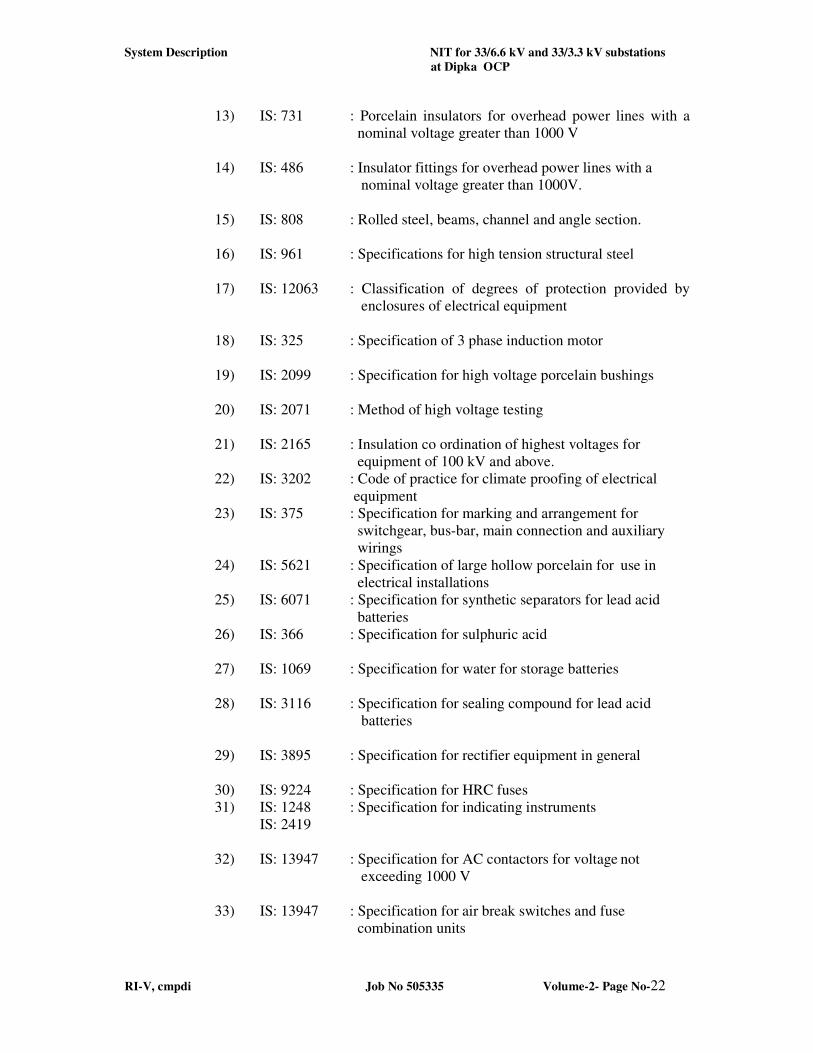
The following Indian Standards / or amended shall be followed for selection
and commissioning of the different equipment. In case of absence of Indian
Standards, Foreign Standards may be adopted after getting the approval from
the Owner. This list is not exhaustive.
1) IS: 2531 : Specification of Danger/Caution Boards
2) IS: 398 : Aluminum conductors, galvanized steel reinforced
3) IS: 5561 : Specification of electric power connectors
4) IS: 802 : Code of practice for use of structural steel on
Transmission towers.
5) IS: 226 : Specification for structural steel (standard quality)
6) IS: 6639 : Specification for hexagonal bolts for steel structures
7) IS: 6610 : Specification of heavy washers for steel structures
8) IS: 2016 : Specification of plain washers
9) IS: 3063 : Specification for spring washers for bolts, nuts and
Screws
10) IS: 4795 : Specification for hot dip zinc coatings on structural
steel and allied products
11) IS: 2629 : Recommended practice for hot-dip galvanizing of iron
and steel
12) IS: 3034 : Code of practice for Earthing
System Description NIT for 33/6.6 kV and 33/3.3 kV substations
at Dipka OCP
RI-V, cmpdi Job No 505335 Volume-2- Page No-22
13) IS: 731 : Porcelain insulators for overhead power lines with a
nominal voltage greater than 1000 V
14) IS: 486 : Insulator fittings for overhead power lines with a
nominal voltage greater than 1000V.
15) IS: 808 : Rolled steel, beams, channel and angle section.
16) IS: 961 : Specifications for high tension structural steel
17) IS: 12063 : Classification of degrees of protection provided by
enclosures of electrical equipment
18) IS: 325 : Specification of 3 phase induction motor
19) IS: 2099 : Specification for high voltage porcelain bushings
20) IS: 2071 : Method of high voltage testing
21) IS: 2165 : Insulation co ordination of highest voltages for
equipment of 100 kV and above.
22) IS: 3202 : Code of practice for climate proofing of electrical
equipment
23) IS: 375 : Specification for marking and arrangement for
switchgear, bus-bar, main connection and auxiliary
wirings
24) IS: 5621 : Specification of large hollow porcelain for use in
electrical installations
25) IS: 6071 : Specification for synthetic separators for lead acid
batteries
26) IS: 366 : Specification for sulphuric acid
27) IS: 1069 : Specification for water for storage batteries
28) IS: 3116 : Specification for sealing compound for lead acid
batteries
29) IS: 3895 : Specification for rectifier equipment in general
30) IS: 9224 : Specification for HRC fuses
31) IS: 1248 : Specification for indicating instruments
IS: 2419
32) IS: 13947 : Specification for AC contactors for voltage not
exceeding 1000 V
33) IS: 13947 : Specification for air break switches and fuse
combination units
System Description NIT for 33/6.6 kV and 33/3.3 kV substations
at Dipka OCP
RI-V, cmpdi Job No 505335 Volume-2- Page No-23
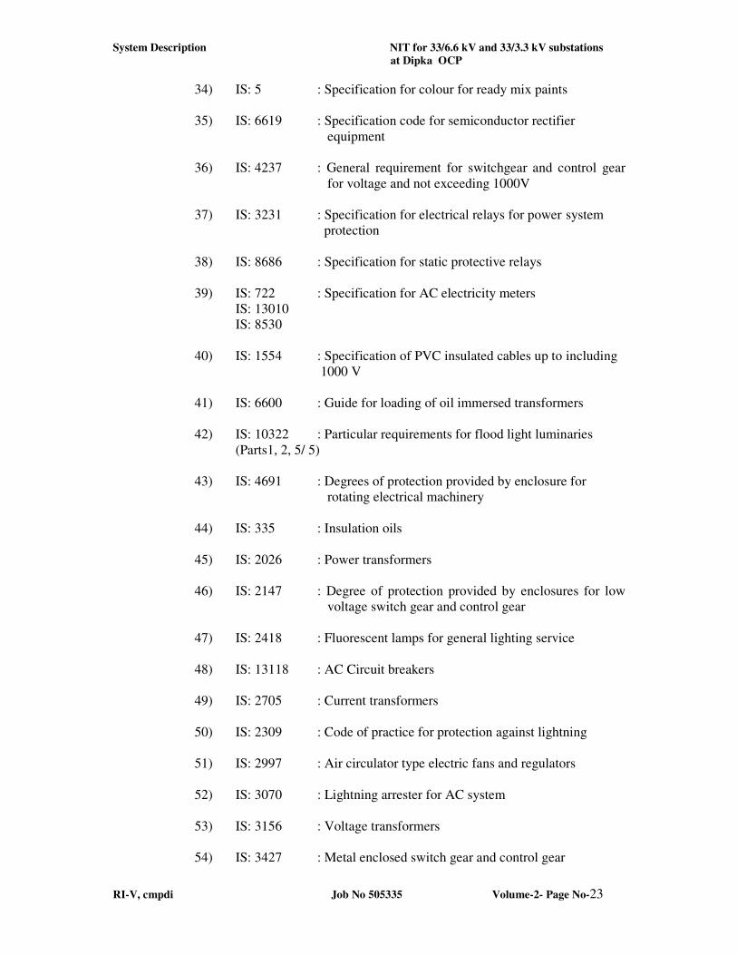
34) IS: 5 : Specification for colour for ready mix paints
35) IS: 6619 : Specification code for semiconductor rectifier
equipment
36) IS: 4237 : General requirement for switchgear and control gear
for voltage and not exceeding 1000V
37) IS: 3231 : Specification for electrical relays for power system
protection
38) IS: 8686 : Specification for static protective relays
39) IS: 722 : Specification for AC electricity meters
IS: 13010
IS: 8530
40) IS: 1554 : Specification of PVC insulated cables up to including
1000 V
41) IS: 6600 : Guide for loading of oil immersed transformers
42) IS: 10322 : Particular requirements for flood light luminaries
(Parts1, 2, 5/ 5)
43) IS: 4691 : Degrees of protection provided by enclosure for
rotating electrical machinery
44) IS: 335 : Insulation oils
45) IS: 2026 : Power transformers
46) IS: 2147 : Degree of protection provided by enclosures for low
voltage switch gear and control gear
47) IS: 2418 : Fluorescent lamps for general lighting service
48) IS: 13118 : AC Circuit breakers
49) IS: 2705 : Current transformers
50) IS: 2309 : Code of practice for protection against lightning
51) IS: 2997 : Air circulator type electric fans and regulators
52) IS: 3070 : Lightning arrester for AC system
53) IS: 3156 : Voltage transformers
54) IS: 3427 : Metal enclosed switch gear and control gear
System Description NIT for 33/6.6 kV and 33/3.3 kV substations
at Dipka OCP
RI-V, cmpdi Job No 505335 Volume-2- Page No-24
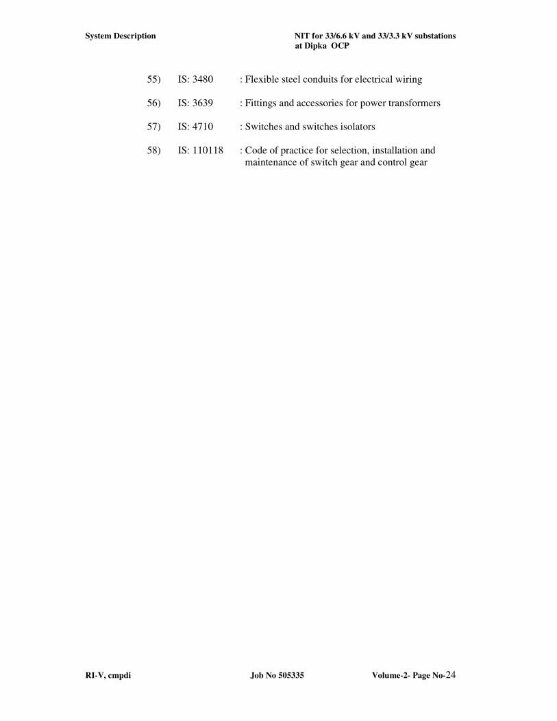
55) IS: 3480 : Flexible steel conduits for electrical wiring
56) IS: 3639 : Fittings and accessories for power transformers
57) IS: 4710 : Switches and switches isolators
58) IS: 110118 : Code of practice for selection, installation and
maintenance of switch gear and control gear
Scope of work NIT of 33 /6. 6 kV and 33/3. 3 kV substations
at Dipka OCP
RI-V, cmpdi Job No 505335 Volume-2- Page No- 25
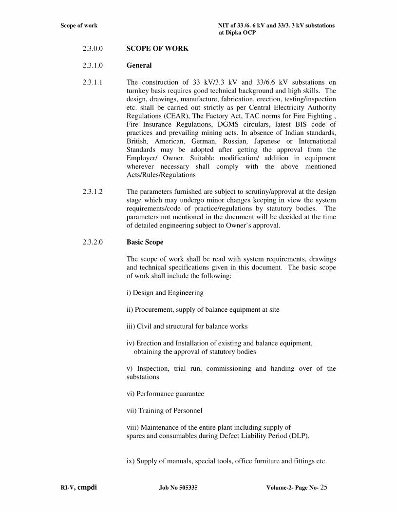
2.3.0.0 SCOPE OF WORK
2.3.1.0 General
2.3.1.1 The construction of 33 kV/3.3 kV and 33/6.6 kV substations on
turnkey basis requires good technical background and high skills. The
design, drawings, manufacture, fabrication, erection, testing/inspection
etc. shall be carried out strictly as per Central Electricity Authority
Regulations (CEAR), The Factory Act, TAC norms for Fire Fighting ,
Fire Insurance Regulations, DGMS circulars, latest BIS code of
practices and prevailing mining acts. In absence of Indian standards,
British, American, German, Russian, Japanese or International
Standards may be adopted after getting the approval from the
Employer/ Owner. Suitable modification/ addition in equipment
wherever necessary shall comply with the above mentioned
Acts/Rules/Regulations
2.3.1.2 The parameters furnished are subject to scrutiny/approval at the design
stage which may undergo minor changes keeping in view the system
requirements/code of practice/regulations by statutory bodies. The
parameters not mentioned in the document will be decided at the time
of detailed engineering subject to Owner’s approval.
2.3.2.0 Basic Scope
The scope of work shall be read with system requirements, drawings
and technical specifications given in this document. The basic scope
of work shall include the following:
i) Design and Engineering
ii) Procurement, supply of balance equipment at site
iii) Civil and structural for balance works
iv) Erection and Installation of existing and balance equipment,
obtaining the approval of statutory bodies
v) Inspection, trial run, commissioning and handing over of the
substations
vi) Performance guarantee
vii) Training of Personnel
viii) Maintenance of the entire plant including supply of
spares and consumables during Defect Liability Period (DLP).
ix) Supply of manuals, special tools, office furniture and fittings etc.
Scope of work NIT of 33 /6. 6 kV and 33/3. 3 kV substations
at Dipka OCP
RI-V, cmpdi Job No 505335 Volume-2- Page No- 26
x) Critical spares
xi) Any other items not mentioned above but are required for the
successful commissioning and operation of the plant
2.3.3.0 Design Engineering
The design engineering shall consist of the following:
2.3.3.1 E&M Engineering
i) Single line diagram showing the details of all the equipment in the
substation (outdoor and indoor)
ii) Preparation of detailed layout drawing of the substation outdoor
yard, arrangement for two pole structure (for outward conductor),
Indoor control room (if not constructed) giving dimensions, clearances
iii) Sectional elevations of the layout in outdoor yard showing
dimensions, clearances and load data wherever necessary
iv) Single line diagram showing the size, type and length of cables for
feeding power to various equipment and cables up to outward two pole
structure
v) Plan showing the cable trenches in the outdoor yard showing the
sizes along with the location and size of transformer oil collecting
chamber.
vi) Drawing showing shield wire arrangement (to protect the outdoor
equipment from direct lightning strokes), showing the size of GI wires,
elevation at which they are provided and other required details
vii) Drawing showing the earthing system provided both in outdoor
yard and inside the control room with dimensions.
viii) General arrangement showing the layout of indoor equipment in
the control room, battery room etc. along with dimensions, clearances,
cable trench details etc.
ix) Plan and elevation showing the position of various luminaries for
outdoor and indoor lighting (including specifications), cable layouts,
location of main and sub distribution boards.
x) Single line diagram showing the control scheme along with details
xi) Emergency lighting system details along with single line diagram
Scope of work NIT of 33 /6. 6 kV and 33/3. 3 kV substations
at Dipka OCP
RI-V, cmpdi Job No 505335 Volume-2- Page No- 27
xii) Details of signaling system along with single line diagram
xiii) Calculations in support of selection of cable sizes, number of
luminaries
xiv) Calculation for step potential and touch potential for sustained
fault and short time fault.
xv) Calculations in support of number of earth pits, conductor size etc.
used for earthing system and lightning protection systems.
xvi) Scheme of protection, time grading of earth fault relays for series
discrimination, isolation from the main substation grounding to
eliminate the potential hazard and monitoring for connection of neutral
resistance.
xvii) Calculations in support of air conditioning requirement for
control room.
xviii) Scheme of Fire Fighting System including Hydrant system and
High Velocity Water Spraying System for Power Transformers
(HVWSS).
xix) Any other drawings as specified in the technical specifications of
the equipment
2.3.4.0 Supply of Equipment
The brief specifications and quantity of balance equipment to be
supplied under this Contract are as given below. Equipment not
mentioned below but required for the completion of the job shall also
be supplied by the Bidder. The scope of supply of equipment shall be
read in conjunction with the system description and Technical
specifications of the Equipment given in this document
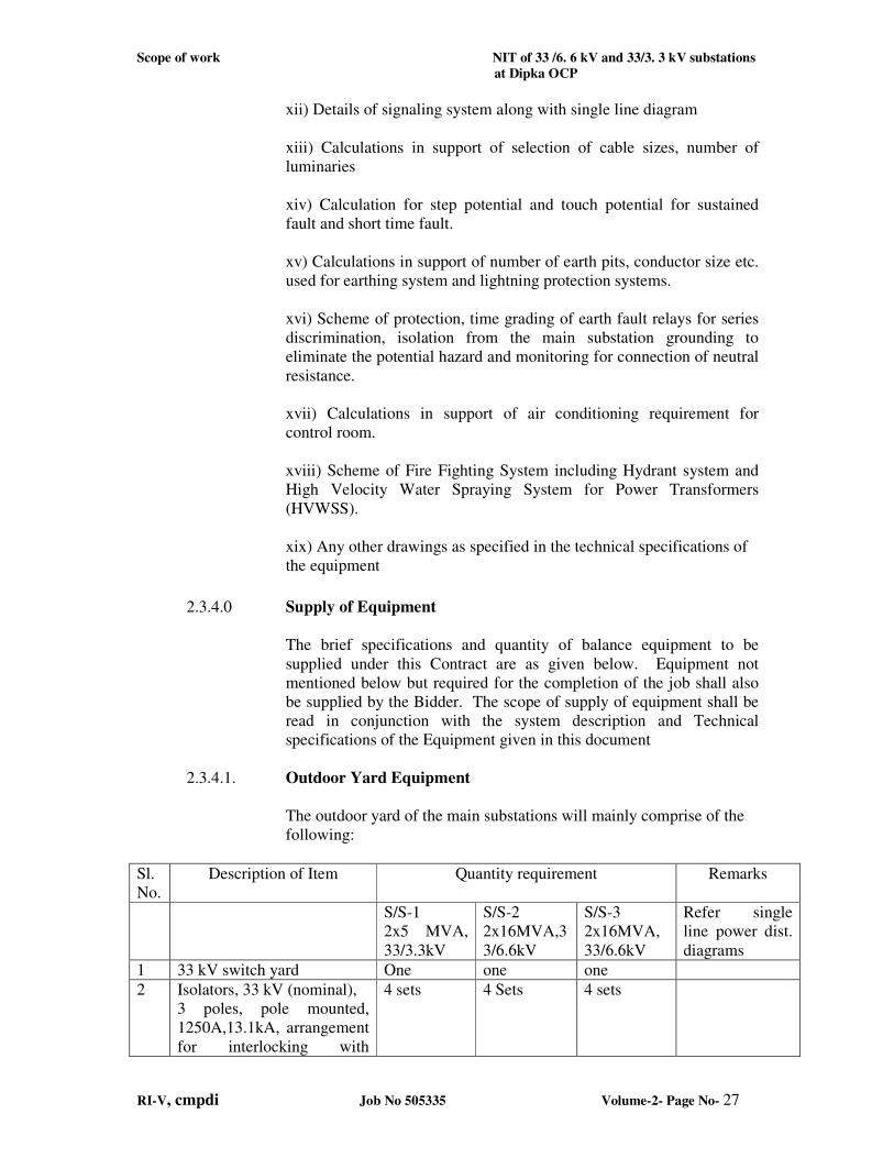
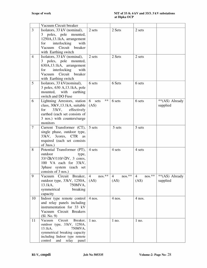
2.3.4.1. Outdoor Yard Equipment
The outdoor yard of the main substations will mainly comprise of the
following:
Sl.
No.
Description of Item Quantity requirement Remarks
S/S-1
2x5 MVA,
33/3.3kV
S/S-2
2x16MVA,3
3/6.6kV
S/S-3
2x16MVA,
33/6.6kV
Refer single
line power dist.
diagrams
1 33 kV switch yard One one one
2 Isolators, 33 kV (nominal),
3 poles, pole mounted,
1250A,13.1kA, arrangement
for interlocking with
4 sets
4 Sets
4 sets
Scope of work NIT of 33 /6. 6 kV and 33/3. 3 kV substations
at Dipka OCP
RI-V, cmpdi Job No 505335 Volume-2- Page No- 28
Vacuum Circuit breaker
3 Isolators, 33 kV (nominal),
3 poles, pole mounted,
1250A,13.1kA, arrangement
for interlocking with
Vacuum Circuit breaker
with Earthing switch
2 sets
2 Sets
2 sets
4 Isolators, 33 kV (nominal),
3 poles, pole mounted,
630A,13.1kA, arrangement
for interlocking with
Vacuum Circuit breaker
with Earthing switch
2 sets
2 Sets
2 sets
5 Isolators, 33 kV(nominal),
3 poles, 630 A,13.1kA, pole
mounted, with earthing
switch and DO Fuse
6 sets
6 Sets
6 sets
6 Lightning Arrestors, station
class, 30kV,13.1kA, suitable
for 33kV, effectively
earthed (each set consists of
3 nos.) with counters/surge
monitors
6 sets **
(AS)
6 sets 6 sets **(AS) Already
supplied
7 Current Transformer (CT),
single phase, outdoor type,
33kV, 3cores, CTR as
required (each set consists
of 3nos.)
5 sets 5 sets 5 sets
8 Potential Transformer (PT),
outdoor type,
33/√3kV/110/√3V, 3 cores,
100 VA each for 33kV,
3phase system (each set
consists of 3 nos.)
4 sets 4 sets 4 sets
9 Vacuum Circuit Breaker,
outdoor type, 33kV, 1250A,
13.1kA, 750MVA,
symmetrical breaking
capacity
4 nos.**
(AS)
4 nos.**
(AS)
4 nos.**
(AS)
**(AS) Already
supplied
10 Indoor type remote control
and relay panels including
instrumentation for 33 kV
Vacuum Circuit Breakers
(Sl. No. 9)
4 nos. 4 nos. 4 nos.
11 Vacuum Circuit Breaker,
outdoor type, 33kV, 1250A,
13.1kA, 750MVA,
symmetrical breaking capacity
including Indoor type remote control and relay panel
1 no. 1 no. 1 no.
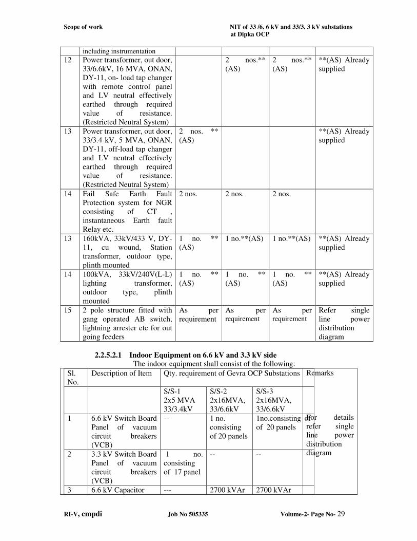
Scope of work NIT of 33 /6. 6 kV and 33/3. 3 kV substations
at Dipka OCP
RI-V, cmpdi Job No 505335 Volume-2- Page No- 29
including instrumentation
12 Power transformer, out door,
33/6.6kV, 16 MVA, ONAN,
DY-11, on- load tap changer
with remote control panel
and LV neutral effectively
earthed through required
value of resistance.
(Restricted Neutral System)
2 nos.**
(AS)
2 nos.**
(AS)
**(AS) Already
supplied
13 Power transformer, out door,
33/3.4 kV, 5 MVA, ONAN,
DY-11, off-load tap changer
and LV neutral effectively
earthed through required
value of resistance.
(Restricted Neutral System)
2 nos. **
(AS)
**(AS) Already
supplied
14 Fail Safe Earth Fault
Protection system for NGR
consisting of CT ,
instantaneous Earth fault
Relay etc.
2 nos. 2 nos. 2 nos.
13 160kVA, 33kV/433 V, DY-
11, cu wound, Station
transformer, outdoor type,
plinth mounted
1 no. **
(AS)
1 no.**(AS) 1 no.**(AS) **(AS) Already
supplied
14 100kVA, 33kV/240V(L-L)
lighting transformer,
outdoor type, plinth
mounted
1 no. **
(AS)
1 no. **
(AS)
1 no. **
(AS)
**(AS) Already
supplied
15 2 pole structure fitted with
gang operated AB switch,
lightning arrester etc for out
going feeders
As per
requirement
As per requirement
As per requirement
Refer single
line power
distribution
diagram
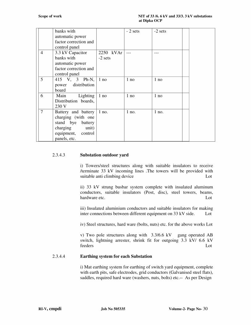
2.2.5.2.1 Indoor Equipment on 6.6 kV and 3.3 kV side The indoor equipment shall consist of the following:
Sl.
No.
Description of Item Qty. requirement of Gevra OCP Substations
S/S-1
2x5 MVA
33/3.4kV
S/S-2
2x16MVA,
33/6.6kV
S/S-3
2x16MVA,
33/6.6kV
1 6.6 kV Switch Board
Panel of vacuum
circuit breakers
(VCB)
-- 1 no.
consisting
of 20 panels
1no.consisting of
of 20 panels
2 3.3 kV Switch Board
Panel of vacuum
circuit breakers
(VCB)
1 no.
consisting
of 17 panel
-- --
3 6.6 kV Capacitor --- 2700 kVAr 2700 kVAr
Remarks
For details
refer single
line power
distribution
diagram
Scope of work NIT of 33 /6. 6 kV and 33/3. 3 kV substations
at Dipka OCP
RI-V, cmpdi Job No 505335 Volume-2- Page No- 30
banks with
automatic power
factor correction and
control panel
- 2 sets -2 sets
4 3.3 kV Capacitor
banks with
automatic power
factor correction and
control panel
2250 kVAr
-2 sets
--- ---
5 415 V, 3 Ph-N,
power distribution
board
1 no 1 no 1 no
6 Main Lighting
Distribution boards,
230 V
1 no 1 no 1 no
7 Battery and battery
charging (with one
stand bye battery
charging unit)
equipment, control
panels, etc.
1 no. 1 no. 1 no.
2.3.4.3 Substation outdoor yard
i) Towers/steel structures along with suitable insulators to receive
/terminate 33 kV incoming lines .The towers will be provided with
suitable anti climbing device Lot
ii) 33 kV strung busbar system complete with insulated aluminum
conductors, suitable insulators (Post, disc), steel towers, beams,
hardware etc. Lot
iii) Insulated aluminium conductors and suitable insulators for making
inter connections between different equipment on 33 kV side. Lot
iv) Steel structures, hard ware (bolts, nuts) etc. for the above works Lot
v) Two pole structures along with 3.3/6.6 kV gang operated AB
switch, lightning arrester, shrink fit for outgoing 3.3 kV/ 6.6 kV
feeders Lot
2.3.4.4 Earthing system for each Substation
i) Mat earthing system for earthing of switch yard equipment, complete
with earth pits, safe electrodes, grid conductors (Galvanised steel flats),
saddles, required hard ware (washers, nuts, bolts) etc.-- As per Design
Scope of work NIT of 33 /6. 6 kV and 33/3. 3 kV substations
at Dipka OCP
RI-V, cmpdi Job No 505335 Volume-2- Page No- 31
ii) Earthing of boundary fencing consisting of earth pits, safe
electrodes, grid conductors (Galvanised steel flats), saddles, required
hardware (washers, nuts, bolts), earthing conductors etc. –
As per Design
iii) Required earth pits, safe electrodes, Galvanised steel flats, saddles,
required hardware etc. for earthing of Transformer neutrals.-
As per Design
iv) Required earth pits, safe electrodes, Galvanised steel flats, saddles,
required hardware etc. for earthing of Lightning arrestors. ----
As per Design
v) Earthing arrangement consisting of earth pits, safe electrodes, grid
conductors (Galvanized steel flats) saddles to be provided around the
substation building, earth conductors from the equipment. ----
As per Design
v) Required piping (at least 13 mm diameter), pipe fittings, valves,
overhead tank etc. for arranging watering arrangement at earth pits. ----
As per Design
vi) Separate neutral grounding resister with relay protection for earth
fault (Restricted Neutral system) on the 3.3 kV or 6.6 kV side of the
main power transformers. - As per design
2.3.4.5 Lightning protection system for each Substation
In addition to the station class lightning arrestors provided for
protecting the equipment, the following shall also be provided.
i) Lightning protection system consisting of steel towers, insulators,
shield wires, down earth conductors, earth pits (Independent of the
earth pits provided for earthing), safe electrodes, GI flats for
connecting earth pits, hardware etc. for out door yard equipment from
direct lightning strokes -- As per Design
ii) Lightning protection system consisting of spikes, galvanised iron
flats, saddles, earth pits with safe electrodes for sub station
building. ---- As per Design
2.3.4.6 Fire fighting system common for each Substation
(i) Portable fire extinguishers (Dry powder type, CO2 type), sand
buckets -- As per Design
(ii) Fire Hydrant system and HVWSS (for power transformers)
with Pumps (Electric, diesel and Jockey) with sump and pump
house
(iii) Fire detection, alarm and protection system.
Scope of work NIT of 33 /6. 6 kV and 33/3. 3 kV substations
at Dipka OCP
RI-V, cmpdi Job No 505335 Volume-2- Page No- 32
2.3.4.7 Lighting system common for each Substation
i) Lighting distribution board, 230V, MCCB s and MCB s for control
of various lighting circuits. – 1 no.
ii) Lighting mast, 16 m height, along with 4 nos. luminaries with 200
W LED lamps, control gear etc. for outdoor yard lighting- 7 nos.
iii) 11 m high steel poles along with luminaries with 90W LED Lamps,
control gear, brackets etc for outdoor yard illumination. –
4 nos.
iv) 90 W LED lamps fitted on sub station building – 4
nos.
v) Lighting of substation building
-1x12 W, 2 x 12 W LED light fittings --
As per Design
-2 x 12 W LED lamps complete with the fittings –
As per Design
vi) Accessories such as sub distribution boards, junction boxes,
individual control cables, PVC conduits/casings, back up fuses,
switches, sockets, ceiling roses, single core PVC cable with copper
conductors (for internal connections) , flexible wire etc.-- Lot
vii) Emergency lighting system suitable for operation on 110 V DC in
substation building ----- Lot.
2.3.4.8 Auxiliary Power supply system
i) Power distribution board (9 panels), 415V, 3 ph N with MCCB s and
back up HRC fuses for control and distribution of AC supply. ---
1 set.
ii) 110V rechargeable battery, SMF type (200 AH. capacity) complete
with two nos. float cum boost chargers, wooden rack etc. ---- 1 set
iii) DC Power distribution board, 110V, with all protections for
supplying power to various installations, emergency lighting - 1 set
2.3.4.9 Cables and accessories
i) HT Power cable from secondary side of the power transformer to 6.6
kV indoor switch board and switch board to outgoing 2 pole structures,
XLPE , FRLS, stranded copper conductors, 6600 V grade of suitable
size and length (for S/S No.-2&3) - Lot
ii) HT Power cable from secondary side of the power transformer to
3.3 kV indoor switch board and switch board to outgoing 2 pole
Scope of work NIT of 33 /6. 6 kV and 33/3. 3 kV substations
at Dipka OCP
RI-V, cmpdi Job No 505335 Volume-2- Page No- 33
structures, XLPE, FRLS, stranded copper conductors, 3300 V grade of
suitable size (for S/S -1) - Lot
iii) LT Power cables for Vacuum circuit breakers, CT’s, PT’s etc.,
PVCSWA, FRLS, 1100V grade, 10 sq mm (minimum), 3/4 core
copper stranded conductors - Lot
iv) Outdoor lighting cable, PVCSWA, copper conductors, 1100 V
grade of suitable size not less than 2core, 10 sq mm (minimum) - Lot
v) Outdoor and indoor control cable, PVCSWA, copper conductors,
1100/660 V grade of suitable size (not less than 2.5 sq mm) and
required numbers of cores -Lot
vi) Wire for internal wiring of illumination, ceiling fans, exhaust fans,
power sockets, air conditioners, water coolers etc 1.5 sq mm and 6 sq
mm size (as per requirement), PVC insulated copper conductor of
1100/660 V grade as per requirement -- Lot
vii) Cables for Internal control wiring for circuit breakers, CT’s, PT’s,
PVC insulated cable, 660V grade, 2.5 sq mm stranded copper
conductors -- Lot.
viii) Cable trays, cable racks, binding material, cable glands, cable
terminal lugs, nuts, bolts, washer, cable jointing and termination kit
etc. -- Lot
2.3.4.10 Misc. items for each Substation
i) Air conditioners, 1.5 t capacity, including servo stabilizer- Lot
ii) Exhaust fan 600 mm sweep in battery room, bath room-- 2 nos.
iii) Ceiling fans, 1200 mm sweep along with electronic regulators in
Engineer’s / Supervisor’s room, testing room, battery room, control
room - 5 nos.
iv) Water cooler with water purifier- 1 no
v) Submersible pump with electricals & cables - 1 no.
vi) Earth resistance testing equipment /megger with galvanized steel
prods - 1 no
vii) Primary injection kit- 1 no
viii) Relay Testing kit - 1 no.
ix) High voltage testing kit- 1 no
x) Oil testing kit- 1 no.
xi) All Test Pro-31 kit- 1 no.
xii) Motorised oil pump- 1 no
xiii) Vacuum cleaner, domestic type- 1 no
2.3.4.11 One number 63 kVA, 415 V, 3 phase,50 Hz Silent type Diesel
generator shall also be supplied and installed at the DG shed in each
substation along with cables, 415 V PDB and change over switch and
required earthing and lighting facilities.
Scope of work NIT of 33 /6. 6 kV and 33/3. 3 kV substations
at Dipka OCP
RI-V, cmpdi Job No 505335 Volume-2- Page No- 34
2.3.4.12 Any other equipment which have not been specifically mentioned but
are required for completion of the substation shall also be supplied.
2.3.5.0 Erection and Installation
The installation of equipment shall be done under the direct
supervision of qualified and experienced personnel if possible by the
personnel from original equipment manufacturer. The installation
shall be as per standard code of practice, Indian electricity
rules/relevant BIS/mine acts
The following shall include under erection of equipment
i) Erection of the outdoor equipment on 33 kV side such as 33 kV
sectionalized strung bus, gantries, isolators, current transformers
(CT’s), potential transformers (PT’s), station class lightning arrester
(LA), vacuum circuit breakers, power transformers (33/3.4 kV or
33/6.6 kV) etc.
ii) Erection of station transformer, lighting transformer, control system,
signalling system (in the control room of the substation building) etc.
iii) Installation of indoor control panels for control of 33 kV vacuum
circuit breakers and 3.3 kV or 6.6 kV power distribution boards, OLTC
of 16 MVA transformers etc in the control room of substation building.
iv)Installation of AC/DC power supply arrangement, LT power
distribution board, lighting distribution boards, emergency lighting
system, Batteries etc. in the substation building.
v) Installation of various luminaries, poles, towers etc. both out door
and indoor
vi) Installations of ceiling fans and exhaust fans.
vii) Installation of Air conditioning system in the control room, water
cooler and water purifier
viii) Installation of submersible pump with electrical
ix) Installation of portable fire extinguishers, sand buckets, hydrant
system and HVWSS with Hoses and Pumps etc.
x) Laying, jointing, termination of power cable, lighting cables and
control cables etc.
xi) Construction of required number of earth pits and their inter
connection to form earthling grid, independent earth pits for earthling
of transformer neutral and lightning arresters, earthling grid for
fencing, independent earthling system around substation building etc.
Scope of work NIT of 33 /6. 6 kV and 33/3. 3 kV substations
at Dipka OCP
RI-V, cmpdi Job No 505335 Volume-2- Page No- 35
xii) Erection of shield wires interconnecting the lightning masts to
protect from direct lightning strokes, lightning mast, required earth pits
and interconnection etc.
xiii) Installation of 63 kVA silent type DG set with required electricals
and earthing
xiv) Installation of drinking water and industrial water supply laying
and termination of GI pipe from the OH tank in the substation building
to various earth pits, required valves etc.
xv) Any other installation of equipment which are not specially
mentioned but required for successful operation of the substation.
2.3.6.0 Inspection, Trial run and Commissioning
2.3.6.1 These will be carried out as specified elsewhere in the Tender
document
2.3.7.0 Performance Guarantee
2.3.8.0 Training of personnel
2.3.9.0 Maintenance during DLP- Maintenance of the entire plant including
supply of spares and consumables during the defect liability period will
be under the scope of the work.
2.3.10.0 Manuals and Tools
2.3.10.1 Type test certificates as given in technical specifications of the
equipment shall be furnished.
2.3.10.2 The tools, safety items, tackles, measuring instruments shall be as
given below.
i) Multi meter for measuring AC & DC (Voltage, current, resistance
etc.) AVO meter 1 no
ii) Tong tester (Digital), 0-1000A, 0-600 V 1no
iii) Motorised Megger, 0-5000V, 1no
0-10000V, 1no
iv) Hand operated crimping tools (0-95 sq mm) 1no
v) Hydraulic crimping tools (10-400 sq mm) 1no
vi) Spanners 1 set (each)
- Full range of ‘D’ spanners
Scope of work NIT of 33 /6. 6 kV and 33/3. 3 kV substations
at Dipka OCP
RI-V, cmpdi Job No 505335 Volume-2- Page No- 36
- Full range of ring spanners
- Full range of box spanners
vii) Full range of screw drivers 1set
viii) Slide wrenches of required size. 1set
ix) Discharge rods, 3 m long along with the hook, cable etc. 2 sets
x) Hand gloves, 15 kV grade. 4sets
xi) Safety Belts 4nos
xii) Manual winch operated 12 m long telescopic FRLS
ladder mounted on big wheels. 1 no
xiii) Extensible platform ladder up to 4.5 m long, FRLS 1 no
xiv) All special tools as detailed in the technical
specifications of equipment As required
xv) Wooden testing bench As required
xvi) Providing and fixing of Danger plates, caution boards as per IE
rules at strategic locations, safety charts, bay identification marks etc.
As required
xvii) Lux meter - 1no
xviii) Soldering kit -1 no
2.3.11.0 Critical spares
2.3.11.1 List of critical spares along with prices shall be as supplied separately
after DLP period by the tenderer. However, owner will scrutinize the
list and order will be placed separately.
2.3.12.0 Other items
i) All the construction equipment, testing instruments, tool and tackles
required for installation and testing shall be brought by the Contractor
ii) The Contractor shall prepare a safety code of practice for these
operations and obtain the approval of Owner
iii) Obtaining the approvals from various Govt. departments for
establishment of 33/3.3 kV and 33/6.6 kV substation and necessary
vetting of the drawings by statutory bodies.
Equipment Specifications NIT of 33/6.6 kV and 33/3.3 kV Sub-stations
at Dipka Opencast Project
RI-V , cmpdi Job No 505335 Volume-2 – Page No- 37
2.4.0.0 TECHNICAL SPECIFICATIONS OF EQUIPMENT
2.4.1.1 SCOPE
This specification covers requirements for 33 kV, Off Load Isolator and Earthing
Switch suitable for outdoor application.
The 33 kV, Off Load Isolator and earthing switch shall comply with the latest revision
of IS: 1818 .
Any material and component not specifically stated in this specification but necessary
for trouble free operation of the equipment and accessories specified herein shall be
deemed to be included.
2.4.1.2 OTHER RELEVANT STANDARDS
The other relevant Indian standards are as under:
IS:3043 : Code of practices for earthing.
IS:11353 : Guide for uniform system of marking and identification of
conductors and apparatus terminals.
IS:5350(Part 3): Dimensions for outdoor porcelain post insulators.
IS:13134 : Guide for selection of Insulators in respect of pollution conditions.
IS:2486 : Insulator fittings for over head power lines with a nominal voltage
greater than 1000 volts.
IS:2099 : Bushings for alternating voltages above 1000 volts.
2.4.1.3 SYSTEM DETAILS
The rotating units shall be supported by thrust/taper roller bearings. All moving parts
shall be fitted with non-ferrous bushes. The operating mechanism shall comprise of
suitable bars and GI pipes of adequate length brought down a pole to a handle
provided with galvanized guides. The same shall have arrangement for padlocking as
OFF and ON position of the switch.
2.4.1.4 DESIGN FEATURES
The design of isolators shall be in accordance with the latest practice. However
following points shall be taken into consideration.
Electrical Features
a) The 33 kV, Off Load Isolator and Earthing Switch shall be suitable for 33000V, 3-
phase, 50 Hz power supply.
b) The isolator shall be designed for an operating temperature of 700C.
c) All similar components shall be interchangeable and shall be of same type and
rating for easy maintenance and low spare inventory.
d) Continuous operation at rated current at specified ambient conditions.
e) Continuous operation within variation for voltage between +10% and frequency
variation between + 3 % and combined voltage and frequency variation of 10%.
f) The rated current carrying capacity, breaking and making capacity of the Isolator
has been specified .
g) The isolator, when earthing switches are used, shall have arrangement for fixing
the same. The earthing switch shall have independent manual drive with
Equipment Specifications NIT of 33/6.6 kV and 33/3.3 kV Sub-stations
at Dipka Opencast Project
RI-V , cmpdi Job No 505335 Volume-2 – Page No- 38
mechanical interlock to prevent mal-operation.
Interlock
Interlocking arrangement shall be provided with the control of circuit breaker to
prevent on load operation of the isolator. In this, necessary numbers of auxiliary
contacts shall be provided on the isolator.
Mechanical Features
The isolator should be fitted with Arching horns to interrupt light load and
magnetizing current on transformer.
The Isolator shall be designed to withstand severe weather conditions and should be
capable of withstanding electro-dynamic stresses due to short circuit.
The incoming and outgoing terminals connections should be suitable for ACSR
conductors (Panther).
2.4.1.5 CONSTRUCTIONAL FEATURES
Switch Blades
The blade shall be made of hard drawn electrolytic copper strips liberal section to give
extra strength and thermal capacity. All copper parts should be silver plated and
ferrous parts metallized to give smooth finish.
Main Bearing
The main baring ball thrust or taper roller bearing supporting the main rotating
insulator operating shaft shall be adjustable in the field if necessary. The insulator
shall be bolted to the top of the sheet steel base of fabricated construction. All
working parts shall be made of non-rusting steel or specially treated to resist corrosion
and the hole shall be brass bushed.
2.4.1.6 FITTINGS AND SPARES
All standard fittings shall be provided
Equipment Specifications NIT of 33/6.6 kV and 33/3.3 kV Sub-stations
at Dipka Opencast Project
RI-V , cmpdi Job No 505335 Volume-2 – Page No- 39
2.4.1.7 TECHNICAL PARAMETERS FOR 33 KV, OFF LOAD ISOLATOR
WITH/WITHOUT EARTHING SWITCH
1. Nominal System Voltage : 33 kV
2. System highest voltage : 36 kV
3. Rated Current : As per requirement
4. Rated Voltage & Frequency : 33 kV, 50 Hz
5. No. of Phases : 3
6. Rated short time current : 13.1 kA (rms) for 3 seconds
7. Rated Current of earthing switch : As per requirement
8. Rated Insulation Level
8.1 One minute power frequency
withstand voltage
: 70 kV rms
8.2 Lightning impulse withstand voltage : 170 kV peak
9. Type of interlock between Isolating
and earthing switch
: Integral Mechanical
10. Operating mechanism : Manual, off load, air break gang
operated outdoor with or without earth
switch
11. Mounting : Structure mounted
12. Type : Horizontal mounted centre, post
rotating, manually operated, double
break with centre post rotating type
with or without earth switch
13. No. of phases per set : Three
14. Contacts : Contact shall be designed to withstand
rated current without over-heating.
The switch shall have self aligning
hard drawn electrolytic copper
contacts.
15. Reference standard : IS: 1818
16. Application : Outdoor
17. Earthing switch : Shall be provided
18. Supporting insulator The supporting insulator shall be 3
nos. of post type brown glazed
porcelain insulator per phase and
tested in accordance with IS: 2544 of
1973 (latest version)
19. Accessories : Base channel of hot dipped galvanized
Equipment Specifications NIT of 33/6.6 kV and 33/3.3 kV Sub-stations
at Dipka Opencast Project
RI-V , cmpdi Job No 505335 Volume-2 – Page No- 40
:
:
:
:
:
iron
Operating down rod with complete
mechanism
Operating handle, mounting base, pad
lock system
Square rod of phase gang operation
Post insulators conforming to IS:
5350.
Earth Switch
.
Equipment Specifications NIT of 33/6.6 kV and 33/3.3 kV Sub-stations
at Dipka Opencast Project
RI-V , cmpdi Job No 505335 Volume-2 – Page No- 41
2.4.2.0 SPECIFICATION OF 33 kV LIGHTNING ARRESTER (LA)
2.4.2.1 SCOPE
This specification covers requirements for 30 kV Surge type Lightning Arrestors at
site and suitable for outdoor application.
The 30 kV Surge type Lightning Arrestors shall comply with the latest revision of IS:
3070 .
Any material and component not specifically stated in this specification but necessary
for trouble free operation of the equipment and accessories specified herein shall
deemed to be included.
2.4.2.2 OTHER RELEVANT STANDARDS
The other relevant Indian standards are as under:
IS: 4004 : Application guide for non linear resistor type surge arrestors.
IS: 5350 : Dimensions for outdoor porcelain post insulators.
2.4.2.3 DESIGN CRITERIA
The 30 kV Surge type Lightning Arrestors shall be suitable for 33000V (+10%), 3-
phase, 50 Hz (+3%) power supply. The nominal discharge current carrying capacity
has been specified at the rated voltage and frequency.
2.4.2.4 CONSTRUCTIONAL FEATURES
The lightning arrestor shall be station class/line type and gapless. The arrestors shall
be composed of units of non-linear resistors made of Zinc oxide.
2.4.2.5 PERFORMANCE
Electrical Features
The lightning arrestor shall ensure:
a) Continuous operation at rated voltage (30 kV & 50 Hz) while carrying out effectively
and without damage the automatic extinction of the follow up current.
b) Continuous operation within variation for voltage between +10%, and frequency
variation between + 3 % and combined voltage and frequency variation of 10%.
c) The arrestors shall divert any switching surge in excess of basic insulation level at the
relevant nominal system voltage and cut off follow-up current of power frequency.
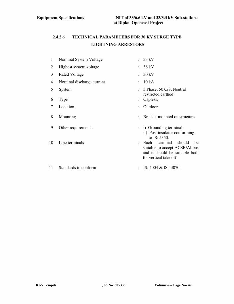
Equipment Specifications NIT of 33/6.6 kV and 33/3.3 kV Sub-stations
at Dipka Opencast Project
RI-V , cmpdi Job No 505335 Volume-2 – Page No- 42
2.4.2.6 TECHNICAL PARAMETERS FOR 30 KV SURGE TYPE
LIGHTNING ARRESTORS
1 Nominal System Voltage : 33 kV
2 Highest system voltage : 36 kV
3 Rated Voltage : 30 kV
4 Nominal discharge current : 10 kA
5 System : 3 Phase, 50 C/S, Neutral
restricted earthed
6 Type : Gapless.
7 Location : Outdoor
8 Mounting : Bracket mounted on structure
9 Other requirements : i) Grounding terminal
ii) Post insulator conforming
to IS: 5350.
10 Line terminals : Each terminal should be
suitable to accept ACSR/Al bus
and it should be suitable both
for vertical take off.
11 Standards to conform : IS: 4004 & IS : 3070.
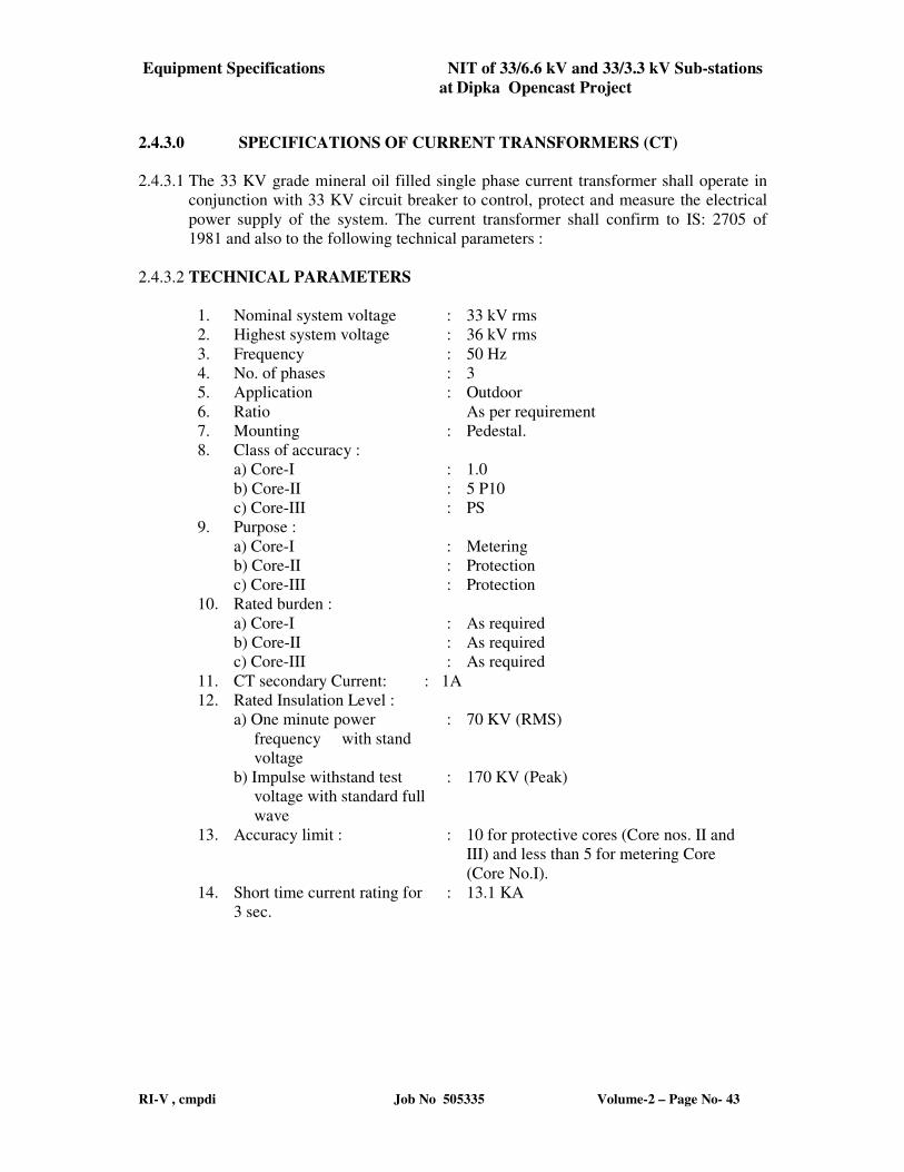
Equipment Specifications NIT of 33/6.6 kV and 33/3.3 kV Sub-stations
at Dipka Opencast Project
RI-V , cmpdi Job No 505335 Volume-2 – Page No- 43
2.4.3.0 SPECIFICATIONS OF CURRENT TRANSFORMERS (CT)
2.4.3.1 The 33 KV grade mineral oil filled single phase current transformer shall operate in
conjunction with 33 KV circuit breaker to control, protect and measure the electrical
power supply of the system. The current transformer shall confirm to IS: 2705 of
1981 and also to the following technical parameters :
2.4.3.2 TECHNICAL PARAMETERS
1. Nominal system voltage : 33 kV rms
2. Highest system voltage : 36 kV rms
3. Frequency : 50 Hz
4. No. of phases : 3
5. Application : Outdoor
6. Ratio As per requirement
7. Mounting : Pedestal.
8. Class of accuracy :
a) Core-I : 1.0
b) Core-II : 5 P10
c) Core-III : PS
9. Purpose :
a) Core-I : Metering
b) Core-II : Protection
c) Core-III : Protection
10. Rated burden :
a) Core-I : As required
b) Core-II : As required
c) Core-III : As required
11. CT secondary Current: : 1A
12. Rated Insulation Level :
a) One minute power
frequency with stand
voltage
: 70 KV (RMS)
b) Impulse withstand test
voltage with standard full
wave
: 170 KV (Peak)
13. Accuracy limit : : 10 for protective cores (Core nos. II and
III) and less than 5 for metering Core
(Core No.I).
14. Short time current rating for
3 sec.
: 13.1 KA
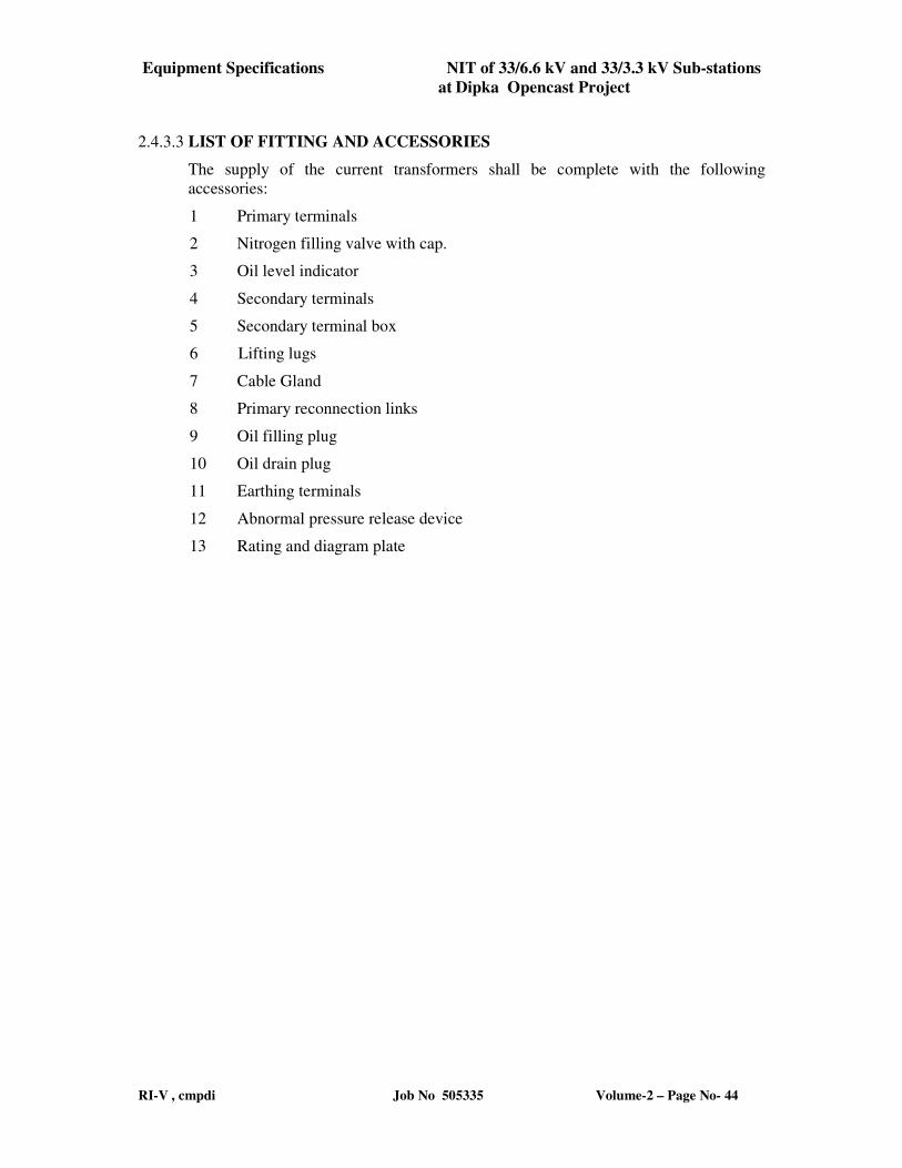
Equipment Specifications NIT of 33/6.6 kV and 33/3.3 kV Sub-stations
at Dipka Opencast Project
RI-V , cmpdi Job No 505335 Volume-2 – Page No- 44
2.4.3.3 LIST OF FITTING AND ACCESSORIES
The supply of the current transformers shall be complete with the following
accessories:
1 Primary terminals
2 Nitrogen filling valve with cap.
3 Oil level indicator
4 Secondary terminals
5 Secondary terminal box
6 Lifting lugs
7 Cable Gland
8 Primary reconnection links
9 Oil filling plug
10 Oil drain plug
11 Earthing terminals
12 Abnormal pressure release device
13 Rating and diagram plate
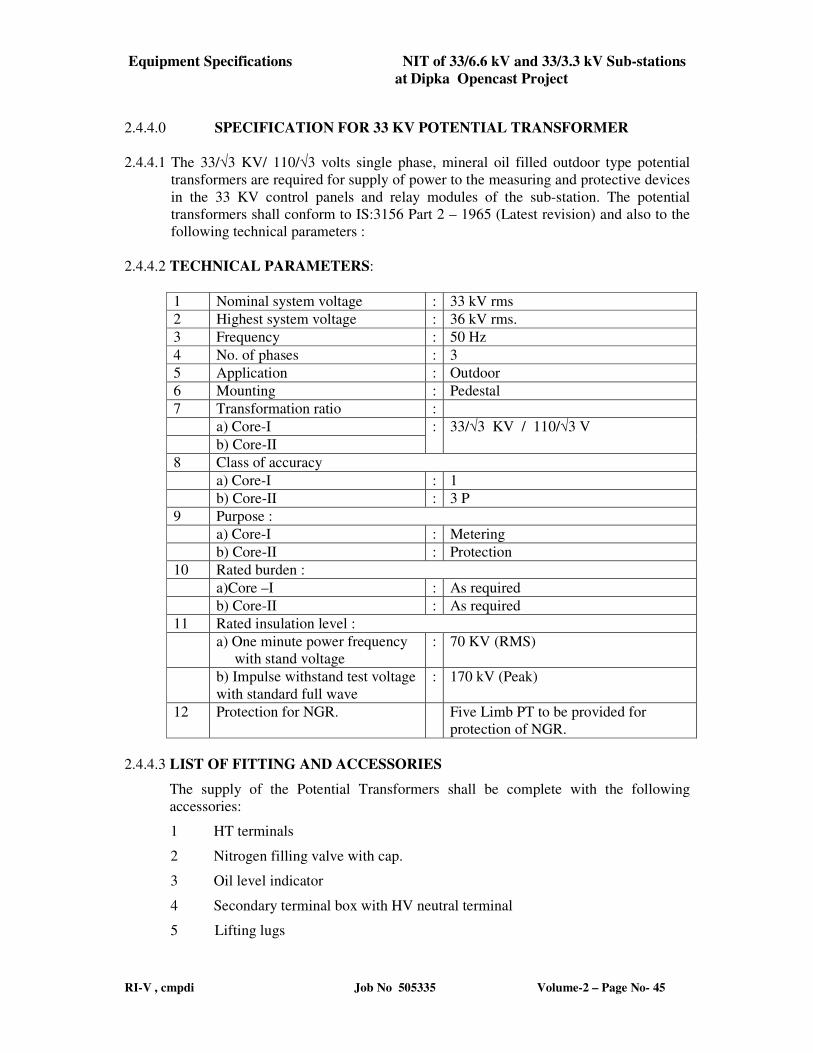
Equipment Specifications NIT of 33/6.6 kV and 33/3.3 kV Sub-stations
at Dipka Opencast Project
RI-V , cmpdi Job No 505335 Volume-2 – Page No- 45
2.4.4.0 SPECIFICATION FOR 33 KV POTENTIAL TRANSFORMER
2.4.4.1 The 33/√3 KV/ 110/√3 volts single phase, mineral oil filled outdoor type potential
transformers are required for supply of power to the measuring and protective devices
in the 33 KV control panels and relay modules of the sub-station. The potential
transformers shall conform to IS:3156 Part 2 – 1965 (Latest revision) and also to the
following technical parameters :
2.4.4.2 TECHNICAL PARAMETERS:
1 Nominal system voltage : 33 kV rms
2 Highest system voltage : 36 kV rms.
3 Frequency : 50 Hz
4 No. of phases : 3
5 Application : Outdoor
6 Mounting : Pedestal
7 Transformation ratio :
a) Core-I : 33/√3 KV / 110/√3 V
b) Core-II
8 Class of accuracy
a) Core-I : 1
b) Core-II : 3 P
9 Purpose :
a) Core-I : Metering
b) Core-II : Protection
10 Rated burden :
a)Core –I : As required
b) Core-II : As required
11 Rated insulation level :
a) One minute power frequency
with stand voltage
: 70 KV (RMS)
b) Impulse withstand test voltage
with standard full wave
: 170 kV (Peak)
12 Protection for NGR. Five Limb PT to be provided for
protection of NGR.
2.4.4.3 LIST OF FITTING AND ACCESSORIES
The supply of the Potential Transformers shall be complete with the following
accessories:
1 HT terminals
2 Nitrogen filling valve with cap.
3 Oil level indicator
4 Secondary terminal box with HV neutral terminal
5 Lifting lugs
Equipment Specifications NIT of 33/6.6 kV and 33/3.3 kV Sub-stations
at Dipka Opencast Project
RI-V , cmpdi Job No 505335 Volume-2 – Page No- 46
6 Oil filling plug
7 Earthing terminals
8 Earthing terminal box.
9 Oil drain plug
10 Abnormal pressure release device
11 Rating and diagram plate
Equipment Specifications NIT of 33/6.6 kV and 33/3.3 kV Sub-stations
at Dipka Opencast Project
RI-V , cmpdi Job No 505335 Volume-2 – Page No- 47
2.4.5.0 SPECIFICATION OF 33 kV, VACUUM CIRCUIT BREAKER
(i) 4 nos. 33 kV VCB ALREADY SUPPLIED WITHOUT CONTROL
AND RELAY PANEL FOR EACH SUBSTATION)
(ii) 1 no. 33 kV VCB WITH INDOOR CONTROL AND RELAY
PANEL FOR EACH SUBSTATION IS TO BE SUPPLIED BY
THE BIDDER
2.4.5.1 Scope
i) This specification covers design, manufacture, assembly, technical details,
operating requirement, constructional details, testing before supply,
inspection, packing, delivery at site of outdoor type AC vacuum circuit
breakers for operating at 50 Hz of rated insulation class of 33 kV. The circuit
breakers shall be of the following types and shall be complete with all the
accessories and auxiliary equipment required for their satisfactory operation in
33 kV/6.6 kV and 33/3.3 kV sub- station.
ii) It is not the intent to specify, completely here- in all the details of design and
construction of the circuit breaker. However, the breaker shall conform, in all
respects to high standards of engineering, design and workmanship as listed
here after. It shall be capable of performing in continuous commercial
operation up to the Contractor’s guarantee in a manner acceptable to the
Employer who will interpret the meanings of drawings and specifications and
shall have power to reject any work or material, which, in his judgment, is not
in accordance therewith. The circuit breaker so offered shall be complete with
all components necessary for its effective and trouble-free operation. Such
components shall be deemed to be within the scope of Contractor’s supply,
irrespective of whether those are specifically brought out in this specification
or not.
2.4.5.2 Technical Parameters of 33 kV, Vacuum Circuit Breaker
i) Nominal system voltage : 33 kV RMS
ii) Highest system voltage : 36 kV RMS
iii) Voltage variation : +/ - (10%)
iv) Rated frequency : 50 Hz
v) Frequency variation : 3% to -5%
vi) Combined voltage and frequency
variation : 0%
vii) Number of phases : 3
Equipment Specifications NIT of 33/6.6 kV and 33/3.3 kV Sub-stations
at Dipka Opencast Project
RI-V , cmpdi Job No 505335 Volume-2 – Page No- 48
viii) Rated continuous current : 1250 Amp
ix) Type : Vacuum
x) Application : outdoor
xi) Short circuit fault interrupting : 750 MVA
capacity
xii) System neutral earthing : Effectively earthed
xiii) Type of operation : Individually three
single poles operated,
single gang operated
pole/three poles
(mechanically poles
coupled) simultaneous
operation.
xiv) Automatic rapid re-closing : Not required
xv) Basic insulation level (Lightning : 170 kV
impulse withstand voltage) (peak)
xvi) One minute power frequency : 70 kV
withstand voltage (rms)
xvii) Auxiliary AC power : 240 V AC +/- 5%
voltage, single phase
xviii) Control circuit voltage : 110V DC +/- 10%
xix) Short time current rating for 3 sec. : 13.1 kA
xx) Operating mechanism : Operating mechanism
shall be spring
charged motor
operated type.
Operation control
shall be electrical
from remote as well
as local. It shall be
trip free
xxi) Number of closing coils : One (Operative from
Equipment Specifications NIT of 33/6.6 kV and 33/3.3 kV Sub-stations
at Dipka Opencast Project
RI-V , cmpdi Job No 505335 Volume-2 – Page No- 49
80%- 110% nominal
voltage)
xxii) Number of shunt trip coil : Two
xxiii) Terminal connector with : Two sets
clamps for ACSR conductor
xxiv) Breaker control cubicle comprising : one set for breaker assembly unit
local/remote selector switch with
indicator lamps and potential free out
put contacts for alarm/trip, contactor
for the spring charge motor,
indicating lamps for breaker status,
closing and trip coils for breaker,
space heater with control switch and
thermostat, socket with switch for
240 V A.C, .hand lamp, required
number of auxiliary relay/ contactors /
MCB fuse links etc.
xxv) Type of breaker control cubicle : Remote
xxvi) Drive motor operating : 80% to110% of nominal
LT voltage
xxvii) Maximum Ambient Temp. : 50 Deg. Centigrade
xxviii) IS to be followed:
a) IS: 13118 High voltage Alternating Current circuit Breakers (with latest
amendments)
b) IS: 12063 Classification of degrees of protection provided by enclosures
of electrical equipment
c) IS: 325 Specification for 3 Phase Induction Motor
d) IS: 2629 Recommended Practice for Hot Dip Galvanising of Iron and
Steel
e) IS: 7311 Seamless high carbon steel cylinders for permanent and
high pressure liquefiable gases.
f) IEC: 2331 High Voltage Porcelain Bushings
g) IEC: 60 High voltage Test Techniques
Equipment Specifications NIT of 33/6.6 kV and 33/3.3 kV Sub-stations
at Dipka Opencast Project
RI-V , cmpdi Job No 505335 Volume-2 – Page No- 50
h) IEC: 71 Insulation Coordination, Terms, Definitions, Principles
Part II and Rules
i) Indian Electricity Rules (with latest Amendments)
j) Fire Insurance Regulations
k) The Indian Electricity (Supply) Act
l) National Fire Code
m) DGMS Regulations
2.4.5.3 Recommended Spares
The Contractor shall furnish in his offer, a list of recommended spares with
unit rates for each circuit breaker that may be necessary for satisfactory
operation and maintenance of the circuit breaker for a period of 2 years. The
Employer reserves the right of selection of items and quantities of these spares
to be ordered. The cost of such spares shall not be considered for tender
evaluation.
2.4.5.4 Erection and Maintenance Tools
As specified elsewhere in the document.
2.4.5.5 Service Condition
i) Environmental Conditions:
The breakers and accessories to be supplied against this specification shall be
suitable for satisfactory continuous operation under the following tropical
conditions.
a) Maximum ambient temperature
(degrees - Centigrade) : 50
b) Maximum ambient temperature in
shade (deg C) : 45
c) Minimum ambient temperature
(deg C) : 4
d) Relative Humidity (%) : 10 to 100
e) Maximum Annual rainfall (mm) : 1400
Equipment Specifications NIT of 33/6.6 kV and 33/3.3 kV Sub-stations
at Dipka Opencast Project
RI-V , cmpdi Job No 505335 Volume-2 – Page No- 51
f) Maximum wind pressure (kg/sq m) : 150
g) Isceraunic level (stormy days
per year ) : 50 (approx.)
h) Moderately hot and humid,
Tropical climate, conducive to rust and
fungus growth : Yes
2.4.5.6 Auxiliary Power Supply
The rating, quality and location of electrical supply system for operation of the
circuit breaker are described below. The auxiliary electrical equipments
provided by the Contractor for specific operation of the circuit breaker, shall
be suitable for operation on the same.
2.4.5.7 Ratings
i) For power devices :240 V +/- 5% three phase 2 wire
(drive motors) 50 Hz Neutral grounded AC supply
ii) For AC control & Protective devices, : 240 V +/- 5%, single phase, 2 wire,
lighting fixtures, space heaters 50 Hz AC supply with one point
and fractional h.p. motors grounded
iii) For DC alarm, control and 2 wire 110 V DC from batteries
protective device.
2.4.5.8 Standards
2.4.5.8.1 The circuit breaker shall conform to the latest revisions, available at the time
of placement of orders of relevant standards, rules and codes listed at in this
document. Equipment meeting with the stipulations of equivalent IEC, ANCI,
CSA, DIN, BS standards, which ensure equal or better quality than the
standards listed in here after, shall also be acceptable. In such case, the
Contractor should submit along with his offer, two copiers of such standards
in authentic English translation, if the language of the standard is other than
English. In case of dispute, the stipulation in the English translation,
submitted by the Contractor shall prevail. Further, in the event of conflict
between the stipulations of standards adopted by the Contractor and the
corresponding Indian Standards Specification, the stipulation of Indian
Standard Specification shall prevail.
2.4.5.9 General Technical Requirements
i) Similar parts of the breaker, especially the removable ones, shall be freely
interchangeable without the necessity of any modification at site.
Equipment Specifications NIT of 33/6.6 kV and 33/3.3 kV Sub-stations
at Dipka Opencast Project
RI-V , cmpdi Job No 505335 Volume-2 – Page No- 52
ii) The breakers will be required to break small inductive currents and line
charging current without causing excessive over voltage, and charging current
without re-strike. The breaker shall also be required to handle evolving faults
and meet the requirements regarding partial discharge, radio interference etc,
as specified in relevant standards.
2.4.5.10 Breaker Contacts
i) Main contacts shall have ample area and contact pressure for carrying the
rated continuous and short time current of the breaker without excessive
temperature- rise which may cause pitting or welding. Contacts shall be
adjustable to allow for wear, shall be easily replaceable and shall have
minimum number of movable parts and adjustments to accomplish test results.
Main contacts shall be the first to open and the last to close so that there will
be little contact burning and wear. Tips of main contacts shall be silver plated.
ii) Arcing contacts, if provided, shall be the first to close and the last to open and
shall be easily accessible for inspection and replacement. The arcing contacts
shall have tungsten alloy tipping
iii) In the case of multi break interrupters, these shall be so designed and
augmented that a fairly uniform voltage distribution is developed across them.
iv) The inside operating rod or insulated fiber glass connecting rods wherever
used, shall be sturdy and shall not break during the entire life period of the
breaker. The insulated rods shall have anti-tracking quality towards electrical
stresses.
2.4.5.11 Take off Terminals Pads
i) Terminal pads shall be provided with silver plating of required thickness , if
these are made of metal other than aluminum. A certificate to this effect is to
be furnished. No such plating shall be required if the terminal pad is made out
of aluminum. The pads shall be suitably designed to take the terminal loads.
The terminal connectors required for connecting the Circuit Breaker to Bus
Bars shall be suitable for mounting on aforesaid terminal pad.
ii) The breaker shall be designed to withstand the rated terminal load, wind
load/Earth quake load and short circuit forces. The short circuit forces to be
considered or the design shall be based on length of bus bar consisting of
conductors and phase to phase spacing.
iii) The current density adopted for the design of the terminal pad shall in no case
exceed 1.6A/sq .mm for copper pad.
iv) The vertical clearance of lowest terminal pad from ground level (including
concrete foundation plinth) shall be approximately as given below:-
36 kV CB - 3.7 m
Equipment Specifications NIT of 33/6.6 kV and 33/3.3 kV Sub-stations
at Dipka Opencast Project
RI-V , cmpdi Job No 505335 Volume-2 – Page No- 53
2.4.5.12 Porcelain Housing
The porcelain housing for the interrupter shall be of a single piece construction
without any joint. It shall be made of homogeneous, vitreous porcelain of
high mechanical and dielectric strength. Glazing of porcelain shall be of
uniform brown or dark brown colour with a smooth surface arranged to shed
away rain water or condensed water particles (fog).
2.4.5.13 Support Insulator
Breaking units shall be mounted on insulator column of multiple insulators of
suitable rating and size in each column
2.4.5.14 Surface Finish
All metal surfaces exposed to atmosphere shall be given two primer coats of
zinc phosphate and two coats of epoxy paints with epoxy base thinner. All
metal parts not accessible for painting shall be made of corrosion resisting
material. All machine finished or bright surfaces shall be coated with a
suitable preventive compound and suitable wrapped or otherwise protected.
All paints shall be carefully selected to withstand tropical heat and extremes of
weather within the limits specified. The paints shall be battleship gray shade
no. 632 of IS 5. The paint shall not scale off or wrinkle or be removed by
abrasion due to normal handling. All components shall be given adequate
treatment of climate proofing as per IS: 3202, so as to withstand corrosion.
2.4.5.15 Galvanising
All ferrous parts including nuts, bolts, plain and spring washers of M10 and
above, support channels, structures, etc. shall be hot dip galvanised to conform
to latest version of IS 2629 or any other equivalent authoritative standard. All
other fixing nuts, bolts, washers of size below M 10 shall be made out of
stainless steel
2.4.5.16 Earthing
The operating mechanism housing, support structures etc. shall be provided
with two separate earthing terminals for bolted connection to 50 x 8 mm MS
flat for connection to station earth mat. The connecting point shall be marked
with “earth” symbol. Earth switch shall be provided to ensure that
- Circuit breaker is not cranked to service position if the switch is closed
- Earth switch cannot be closed when the circuit breaker is in service
condition
Equipment Specifications NIT of 33/6.6 kV and 33/3.3 kV Sub-stations
at Dipka Opencast Project
RI-V , cmpdi Job No 505335 Volume-2 – Page No- 54
2.4.5.17 Name and Rating Plate
i) Circuit breaker and its operating device shall be provided with rating plate
made out of photo finish type plates, marked with the following data. The
data shall be either punched or engraved on the plate and name plate surface
should be coated with colour less epoxy powder.
a) Manufacturer’s name or trade mark by which he may be readily identified.
b) Serial number and type designation
c) Year of manufacture
d) Rated voltage
e) Rated lightning impulse withstand voltage
f) Rated switching impulse withstand voltage
g) Rated normal current
h) Rated short circuit breaking current
i) Rated duration of short circuit
j) Rated auxiliary D.C. supply voltage of closing and opening devices.
k) Rated out of phase breaking current
l) Rated supply voltage of auxiliary circuit
m) Rated insulation level
n) Rated frequency
o) 1st pole -to -clear factor
p) Rated line-charging breaking current
q) Contractor/purchase order reference
r) Rated operating duty
ii) The rating plates shall be installed in such positions that the same are
clearly visible to man standing on ground.
iii) The coils of operating devices shall be marked clearly with the catalogue
number/reference number as indicated in control wiring diagram.
Equipment Specifications NIT of 33/6.6 kV and 33/3.3 kV Sub-stations
at Dipka Opencast Project
RI-V , cmpdi Job No 505335 Volume-2 – Page No- 55
2.4.5.18 Control Circuits
The control circuit shall include the following features:
i) Two electrically independent trip circuits including two trip coils per pole
for 33 kV circuit breakers.
ii) One local / remote selector switch
iii) Conveniently located manual emergency trip
iv) Anti pumping feature
v) Auxiliary switches as specified elsewhere
vi) Independence of trip circuit from local/remote selection
vii) Alarms, indications, monitoring equipment interlocks as specified
elsewhere
viii) Trip circuit supervision for pre trip as well as post trip. 2 numbers per
breaker for 33 kV
ix) The trip circuit supervision relays shall be capable of monitoring the trip
circuits irrespective of whether the breaker is open or closed.
x) Separate cabinets shall be provided for housing operating mechanism and
control circuit. These cabinets shall meet the standard requirements.
2.4.5.19 Auxiliary Switches
Each operating mechanism of the circuit breaker shall be provided with
Cam/snap type auxiliary switches with minimum Ten (10) normally open and
Ten (10) normally closed contacts exclusively for other use with continuous
current rating of 10 Amp. D.C. Breaking capacity of the contacts shall be
minimum 2 A with circuit time constant less than 20 mille seconds at the rated
D.C. voltage. Normal position of auxiliary switches refers to contact position
when circuit breaker is open.
2.4.5.20 Alarm’s and Indications
Potential free contacts shall be provided, duly wired up to the operating
mechanism housing/control cabinet for the following alarms and indications
on control panel.
i) Alarms
Equipment Specifications NIT of 33/6.6 kV and 33/3.3 kV Sub-stations
at Dipka Opencast Project
RI-V , cmpdi Job No 505335 Volume-2 – Page No- 56
a) Auxiliary A.C. supply failure
b) Low operating air pressure
ii) Indications
Breaker on-off
iii) Mechanical indications
The operating mechanism housing shall be provided with the following
mechanical indication/counters:
a) Breaker on-off
b) Operation to register the number of breaker operations.
2.4.5.21 Interlocks
It is proposed to electrically interlock the circuit breaker with isolators in the
switch yard in accordance with switch yard safety interlocking scheme. The
details of the scheme shall be furnished by the successful Contractor. The
requirement of auxiliary contacts to be provided in breaker operating
mechanism for successful operation of the scheme has to be specified by the
Contractor. Key type mechanical interlocking shall also be provided between
circuit breaker and isolator to facilitate maintenance works. All types of
interlocks required in addition to above ,considering the total system , shall
also be provided.
2.4.5.22 Mounting
i) The design and construction of support structure, required for mounting the
Circuit Breaker in switch yard, will be lattice type or tubular type or structural
stool and shall be made out of hot dip galvanized steel. Wheel mounted type
support shall not be accepted. The support structure will be installed on a
concrete plinth of at least 300 mm height to be constructed by the Contractor.
The height of the support structure will meet following requirements.
a) Vertical clearance of lowest terminal pad as specified else where above.
b) Minimum height above the top of concrete plinth shall be maintained as per
the statutory requirement.
ii) The Circuit Breaker shall be connected to adjacent equipment in the switch
yard through insulated aluminum conductor. The maximum unsupported
length of conductor on both sides of the Circuit Breaker shall be as per
accepted standard practices.
Equipment Specifications NIT of 33/6.6 kV and 33/3.3 kV Sub-stations
at Dipka Opencast Project
RI-V , cmpdi Job No 505335 Volume-2 – Page No- 57
iii) The loading data to be considered by the Contractor for design of support
structure shall include the following :
a) Dead weight of the Circuit Breaker, Structure, Bus bars
b) Operational steady state and impact loading.
c) Wind load on a Circuit Breaker, Structure, Bus bars
d) Short circuit forces.
iv)The support structure shall be designed on the basis of applicable
Indian/International Standards and Codes of Practice.
v) The Contractor shall furnish following details along with first lot of
Drawings to be submitted by him along with the schedule.
a) Mechanical loading data considered for design of support structure. This
data should be supported by calculations.
b) Detailed structural Design calculations
2.4.5.23 Operating Mechanism and Associated Equipment
i) The circuit breaker shall be designed for electrical local and remote
control. In addition there shall be provision for local mechanical
control.
ii) The operating mechanism shall be of spring charge motor operated
type operated by electrical control under normal operation. The
mechanism shall be adequately designed for the specified tripping and
closing duty. The entire operating mechanism, control circuitry,
individual breaker spring charge motor etc. as required, shall be housed
in an outdoor type, hot dip galvanised steel enclosure. This enclosure
shall conform to the degree of protection IP-55 of IS-12063. The
enclosure shall invariably be mounted on a separate concrete plinth of
at least 300 mm height.
i) The mechanism shall be provided with motor starter fitted with
overload release, auxiliary switches and socket for inspection lamp.
The charging of springs shall be done by a 240 V AC single phase
motor. The remote control switch will be provided on the control
panel. Closing and tripping devices shall operate at 110 Volts DC. It is
envisaged that C.T. operated direct acting trip coil will also be fitted
for reliable operation. Some of the important precautions required are
mentioned below ;
-the spring, if charged cannot be released when the circuit breaker is
closed.
Equipment Specifications NIT of 33/6.6 kV and 33/3.3 kV Sub-stations
at Dipka Opencast Project
RI-V , cmpdi Job No 505335 Volume-2 – Page No- 58
-Interlock shall be provided to prevent slow closing or opening of the
circuit breaker in its service position.
-If the spring fails, it should be possible to close the circuit breaker
manually
-It should be possible to recharge the spring automatically while the
circuit breaker is closed, thus preparing in advance for the next closing
operation.
- Necessary limit switches shall be incorporated in the automatic spring
charging circuit. The release of the spring shall be by electrically operated
coil for remote control. An emergency hand release should be provided to
work in case of power supply failure.
The vacuum interrupter should enable the metal vapour for arc discharge
through the plasma and is extinguished near current zero. The conductive
metal vapour should condense within a few micro second leading to the rapid
build up of dielectric strength across the open contact gap.
iv) All metal parts in the mechanism shall be of corrosion resistant material.
All bearings which require greasing shall be equipped with pressure grease
fittings.
v) The design of the operating mechanism shall be such that it shall be
practically maintenance free. The guaranteed number of years of maintenance
free operation, the number of possible full load and full rated short circuit
current breaking operations without requiring any maintenance or overhauling
shall be clearly stated in offer. As far as possible, the need for lubricating the
operating mechanism shall be kept to the minimum and eliminated altogether,
if possible.
vi) The operating mechanism shall be anti pumping and trip- free. There shall
be no rebounds in the mechanism and it shall not require any critical
adjustments at site. Operation of the power operated closing device, when the
circuit breaker is already closed, shall not cause damage to the circuit breaker
or endanger the operator.
vii) Provision shall be made for attaching an operation analyser to facilitate
testing of breaker at site.
2.4.5.24 Operating Mechanism Housing
i) Operating mechanism and all accessories shall be enclosed in a weather-
proof cabinet of hot dip galvanised sheet steel construction, the thickness of
which shall not be less than 3 mm. Hinged doors giving access to the
mechanism at the front and sides shall be provided.
ii) Suitable space heaters shall be mounted in the housing to prevent
condensation. Heaters shall be controlled by differential thermostat so
that the cubicle temperature is always, maintained approximately 5
Equipment Specifications NIT of 33/6.6 kV and 33/3.3 kV Sub-stations
at Dipka Opencast Project
RI-V , cmpdi Job No 505335 Volume-2 – Page No- 59
deg. C above the outside air temperature. ON/Off switch and fuse
shall be provided for the heaters. Heaters shall be suitable for 240 V
AC single phase supply. The heater leads shall be covered with
porcelain material upto sufficient length to avoid melting of insulation
of the leads.
2.4.5.25 Specification for Operating Mechanism, Housing and Control Cabinets
i) The control cabinets shall be of free standing floor mounting type.
ii) Control cabinets shall be sheet steel enclosed and shall be dust, water and
vermin proof. Sheet steel shall be at least 2.6 mm thick when control cabinets
are specified for indoor use and at least 3.0 mm thick when control cabinets
are intended for outdoor operation. There shall be sufficient reinforcement to
provide level surfaces, resistance to vibrations and rigidity during
transportation and installation. Control cabinets shall be provided with double
hinged door and padlocking arrangements. The door hinges shall be of union
joint type to facilitate easy removal and the distance between hinges shall not
exceed 350 mm. Door shall be properly braced to prevent wobbling.
iii) Equipment and devices shall be suitable for operation on specified
auxiliary AC supply system
iv) Motors rated 1 kW and above being controlled from the control cabinet
would be suitable for operation on a 415V, +/- 6%, 3 phase 50 Hz system.
Fractional kW motors would be suitable for operation on a 240 V, +/- 6%, 1
phase, 50 Hz AC supply system.
v) Push button shall be rated for not less than 6 Amps, 415 Volts AC or 2
Amps, 110 V DC and shall be flush mounted on the cabinet door and provided
with appropriate name plates. Red, green and amber indicating lamps shall be
flush mounted and provided with series resistors.
vi) Contactor shall be provided with a three element, positive acting ambient
temperature compensated, time lagged, hand reset type thermal over load relay
with adjustable setting. Hand reset button shall be flushed with the front door
of the cabinet and suitable for resetting with starter compartment door closed.
Relays shall be either direct connected or CT operated depending on the rated
motor current.
vii) Single phasing and thermal over load protection shall be provided for all
three phase motors.
viii) Power cables will be of 1100 Volt grade stranded copper conductor, PVC
sheathed single steel wire armoured FRLS type and PVC jacketed. All
necessary wiring will be complete with cable terminating accessories such as
Equipment Specifications NIT of 33/6.6 kV and 33/3.3 kV Sub-stations
at Dipka Opencast Project
RI-V , cmpdi Job No 505335 Volume-2 – Page No- 60
glands, crimp type tinned copper lugs etc. for power as well as control cables.
Suitable brass cable glands shall be provided for cable entry.
ix) Wiring for all control circuits shall be carried out with 1100 Volts grade
PVC insulated tinned copper stranded conductors of sizes not smaller than 2.5
sq. mm. At least 20% spare terminal blocks for control wire terminations shall
be provided on each panel. The terminal blocks shall be similar ELMEX type
CAT-44 or better type. All terminals shall be provided with ferrules indelibly
marked or numbered and these identifications shall correspond to the
designations on the relevant wiring diagrams. The terminals shall be rated for
adequate capacity; which shall not be less than 10 Amps.
x) Control cabinet shall be provided with 240 V, 1 phase 50 Hz., 11 W
compact fluorescent lighting fixture with on/off switch and a suitable rated
240 , 1 phase, 5 Amp, 3 pin socket for hand lamp.
xi) Suitable heaters shall be provided inside each cabinet. Heaters shall be
controlled by suitable toggle switch of industrial quality.
xii) All AC control equipment shall be suitable for operation on 240V, +/-6% ,
1 phase two wire 50 Hz system, with neutral grounded.
xiii) Items inside the cabinet made of organic material shall be coated with a
fungus resistant varnish.
2.4.5.26 Tests
i) Type Tests
a) The equipment / material offered in the tender should be successfully type
tested in line with standard technical specification within the last 5 (five) years
from the date of opening of the tender. The Contractor shall be required to
submit four copies of the type test reports along with the offer.
b) If there is any change in the components or design in the equipment since
after earlier passing of the type test, the Contractor shall bring out in his offer
all such changes made in components, material, designs, etc. In such cases,
the bidder shall carry out the type test at his cost and in presence of the
representative of Employer.
c) Even if the equipment/material has been type tested earlier, the Employer
reserves the right to demand repetition on one or more test included in the list
of type test in the presence of representative.
d) The Employer reserves the right to conduct tests included in the list of type
tests on requisite number of samples/items at Contractor’s cost in the presence
of Employer’s representative. If the equipment/material does not withstand
the type test, then the equipment/material supplied will be liable for rejection.
The Contractor, in such an eventuality, shall be allowed to modify the

Equipment Specifications NIT of 33/6.6 kV and 33/3.3 kV Sub-stations
at Dipka Opencast Project
RI-V , cmpdi Job No 505335 Volume-2 – Page No- 61
equipment and type test the same again at his cost in the presence of the
Employer’s representative. These type tests shall however be conducted by
the Contractor within a reasonable time. After successful passing of the type
tests, all the equipment/material supplied shall be modified in line with the
equipment/materials which have successfully passed the type test. In case
Contractor fails to carry out the type test within reasonable time or does not
agree to carry out the type test at his cost, his equipment/material supplied
earlier shall be rejected and payments made earlier for these equipment shall
be recovered by the Employer.
ii) Acceptance and routine tests
a) All acceptance and routine tests as stipulated in IS: 13118 – 1991 shall be
carried out by the Contractor in the presence of Employer’s representative
without any extra cost to the Employer.
b) After the finalisation of the program of type/acceptance/ routine tests the
Contractor shall give three weeks advance intimation to the Employer to
enable him to depute his representatives for witnessing the tests.
c) The inspection may be carried out by the Employer at any stage of
manufacture. The Contractor shall grant free access to the Employer’s
representative/s at a reasonable notice when the work is in progress.
Inspection and acceptance of any equipment under this specification shall not
relieve the Contractor of his obligation of furnishing equipment in accordance
with the specification and shall not prevent subsequent rejection of the
equipment found to be defective.
d) The supplier shall keep the Employer informed in advance, about the
manufacturing program so that arrangement can be made for stage inspection.
e) The Employer reserves the right to insist for witnessing the
acceptance/routing testing of the items. The Contractor shall keep the
Employer informed, in advance, about such testing program.
2.4.5.30 Drawings
The following drawings have been supplied with 33 kV VCB ;
i) General out line drawing of the Breaker indicating foundation details,
overall dimensions, net and gross weight etc.
ii) Detailed drawings for the operating mechanism.
iii) Out line drawings of the bushings
iv) Sectional views showing the general constructional features of the breaker
and operating mechanism.
Equipment Specifications NIT of 33/6.6 kV and 33/3.3 kV Sub-stations
at Dipka Opencast Project
RI-V , cmpdi Job No 505335 Volume-2 – Page No- 62
2.4.6.0. SPECIFICATION OF 5 MVA, 33/3.4 kV AND 16MVA, 33/6.6 kV OUTDOOR
TYPE TRANSFORMERS
(5 MVA,33/3.4 kV transformers with off-load tap changers and 16 MVA, 33/6.6
kV Transformers with on load tap changers have already been supplied)
2.4.6.1 General
In the Substation No. 2 and 3 (one each in eastern and western flanks), two
transformers each of 2x 16 MVA, 33/6.6 kV Transformers will be installed. In the
sub-station No.–1, two numbers of 5 MVA, 33/3.4 kV transformers will be installed.
The 16 MVA transformer will be with on- load tap changer with remote control panel.
It is proposed that the transformers installed in one substation will be identical in all
respects. The transformers shall be core type, two winding and oil immersed. The type
of cooling shall be ONAN. The transformers shall be supplied with first fill oil.
2.4.6.2 SCOPE
This specification covers the requirements for two winding power transformer
protected by primary circuit breaker, alarm, temperature indicator, tap change,
marshalling box and neutral grounding resistors. The exact voltage ratio and kVA
rating of the transformer has been specified else where in the document.
The transformers shall comply with the latest revisions of IS: 2026 and IEV: 76
except where modified or extended by the provisions of this specification and relevant
parts of standards.
Material and component not specifically stated in this specification but necessary for
trouble free operation of the equipment and accessories specified herein shall be
deemed to be included.
2.4.6.3 Technical Parameters:
i)(a) Nominal system voltage, Number of : 1) Primary - 33 kV
phases and frequency. 3 phases, 50 Hz
2) Secondary – 6.6 or 3.4
kV, 3 phases, 50 Hz (as
per requirements).
I (b) Highest system voltage, 1) Primary - 36 kV
2) Secondary7.2 or 3.6 kV
(as per requirements)
ii) Capacity 16 MVA (ONAN)/
5 MVA (ONAN)
iii) Type of cooling : ONAN
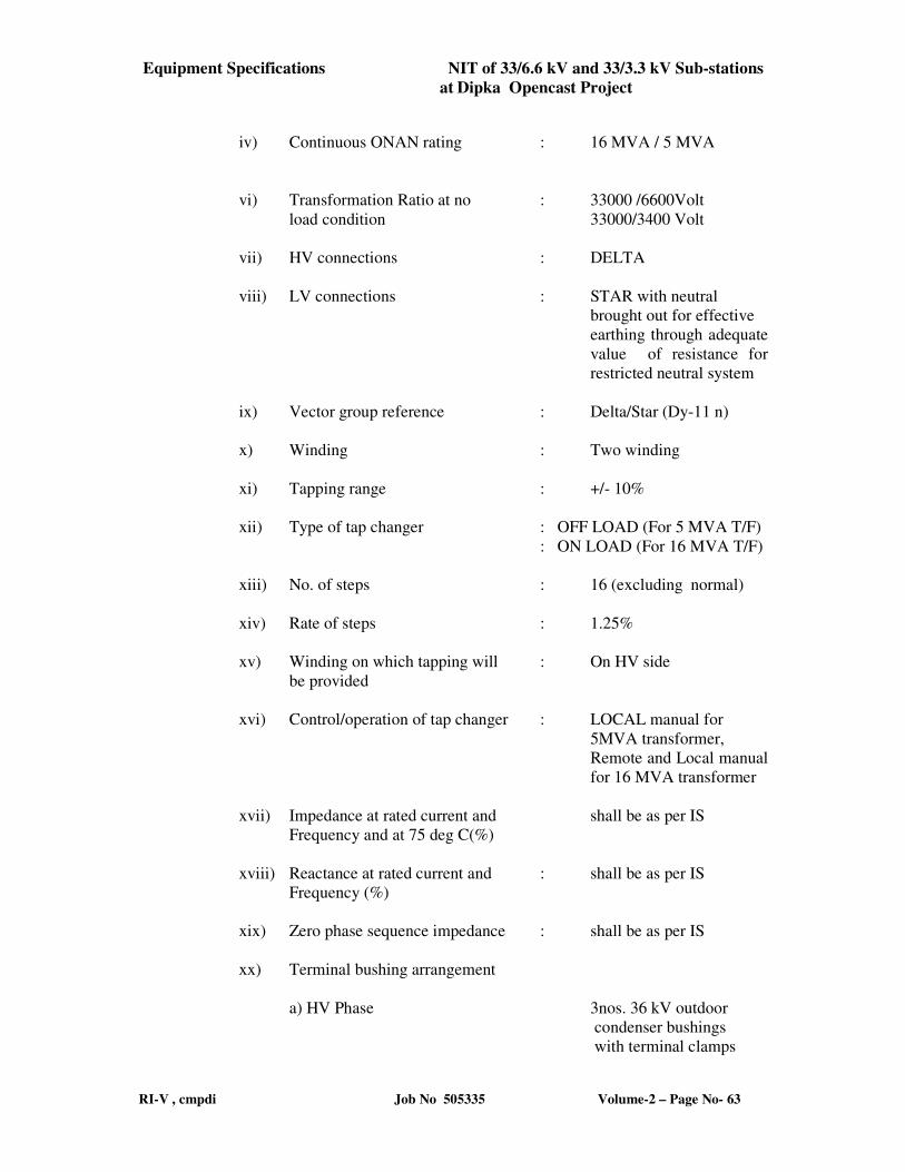
Equipment Specifications NIT of 33/6.6 kV and 33/3.3 kV Sub-stations
at Dipka Opencast Project
RI-V , cmpdi Job No 505335 Volume-2 – Page No- 63
iv) Continuous ONAN rating : 16 MVA / 5 MVA
vi) Transformation Ratio at no : 33000 /6600Volt
load condition 33000/3400 Volt
vii) HV connections : DELTA
viii) LV connections : STAR with neutral
brought out for effective
earthing through adequate
value of resistance for
restricted neutral system
ix) Vector group reference : Delta/Star (Dy-11 n)
x) Winding : Two winding
xi) Tapping range : +/- 10%
xii) Type of tap changer : OFF LOAD (For 5 MVA T/F)
: ON LOAD (For 16 MVA T/F)
xiii) No. of steps : 16 (excluding normal)
xiv) Rate of steps : 1.25%
xv) Winding on which tapping will : On HV side
be provided
xvi) Control/operation of tap changer : LOCAL manual for
5MVA transformer,
Remote and Local manual
for 16 MVA transformer
xvii) Impedance at rated current and shall be as per IS
Frequency and at 75 deg C(%)
xviii) Reactance at rated current and : shall be as per IS
Frequency (%)
xix) Zero phase sequence impedance : shall be as per IS
xx) Terminal bushing arrangement
a) HV Phase 3nos. 36 kV outdoor
condenser bushings
with terminal clamps
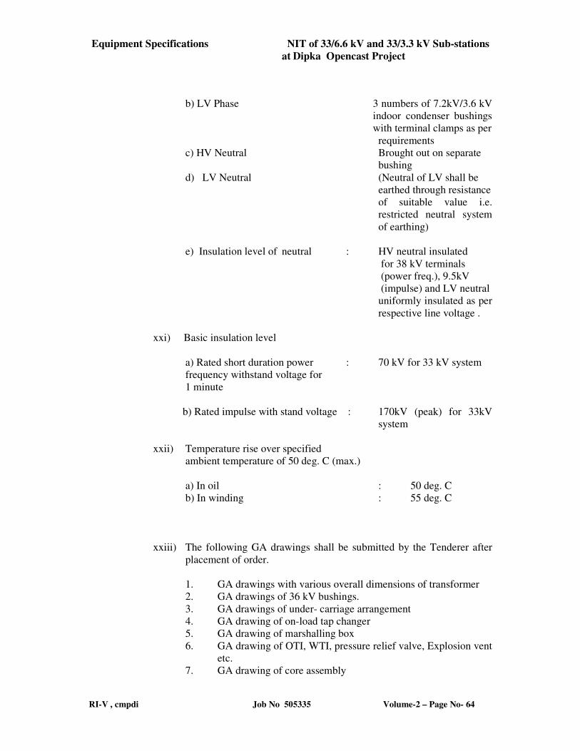
Equipment Specifications NIT of 33/6.6 kV and 33/3.3 kV Sub-stations
at Dipka Opencast Project
RI-V , cmpdi Job No 505335 Volume-2 – Page No- 64
b) LV Phase 3 numbers of 7.2kV/3.6 kV
indoor condenser bushings
with terminal clamps as per
requirements
c) HV Neutral Brought out on separate
bushing
d) LV Neutral (Neutral of LV shall be
earthed through resistance
of suitable value i.e.
restricted neutral system
of earthing)
e) Insulation level of neutral : HV neutral insulated
for 38 kV terminals
(power freq.), 9.5kV
(impulse) and LV neutral
uniformly insulated as per
respective line voltage .
xxi) Basic insulation level
a) Rated short duration power : 70 kV for 33 kV system
frequency withstand voltage for
1 minute
b) Rated impulse with stand voltage : 170kV (peak) for 33kV
system
xxii) Temperature rise over specified
ambient temperature of 50 deg. C (max.)
a) In oil : 50 deg. C
b) In winding : 55 deg. C
xxiii) The following GA drawings shall be submitted by the Tenderer after
placement of order.
1. GA drawings with various overall dimensions of transformer
2. GA drawings of 36 kV bushings.
3. GA drawings of under- carriage arrangement
4. GA drawing of on-load tap changer
5. GA drawing of marshalling box
6. GA drawing of OTI, WTI, pressure relief valve, Explosion vent
etc.
7. GA drawing of core assembly
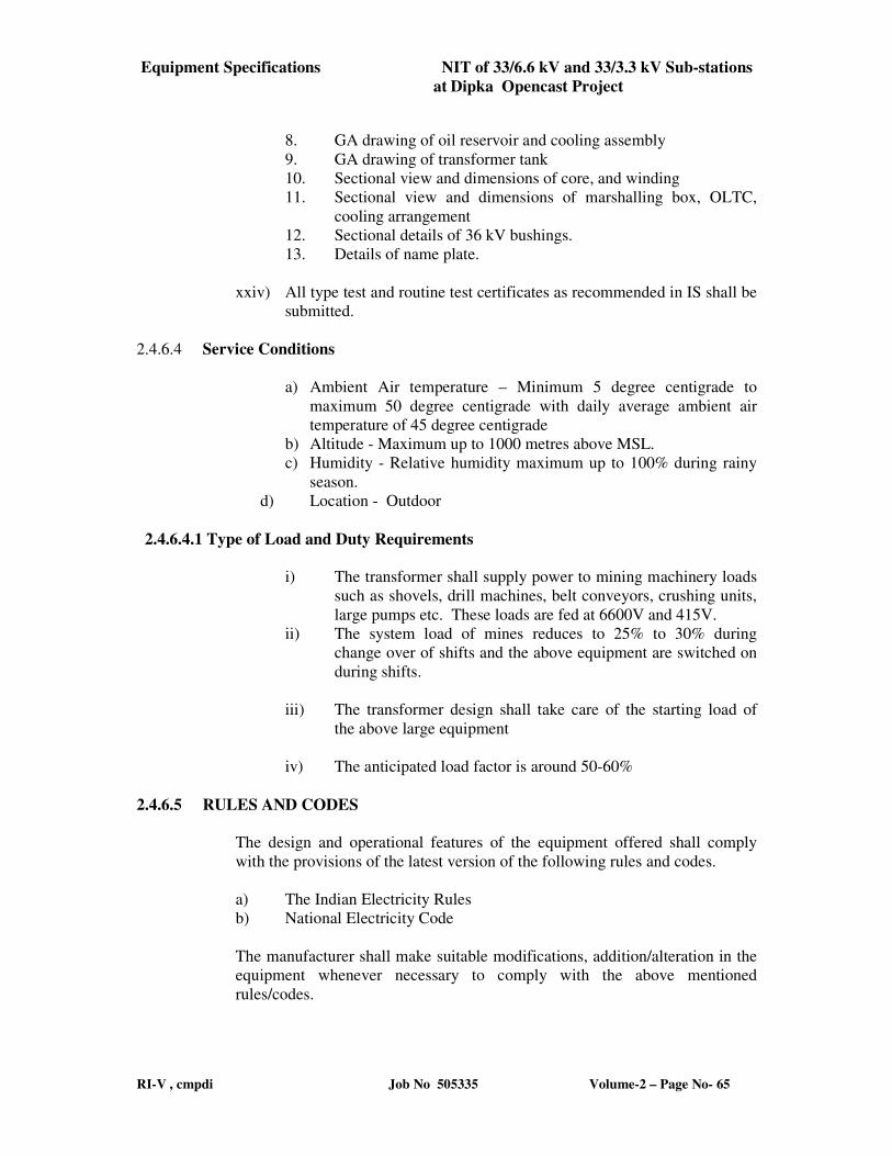
Equipment Specifications NIT of 33/6.6 kV and 33/3.3 kV Sub-stations
at Dipka Opencast Project
RI-V , cmpdi Job No 505335 Volume-2 – Page No- 65
8. GA drawing of oil reservoir and cooling assembly
9. GA drawing of transformer tank
10. Sectional view and dimensions of core, and winding
11. Sectional view and dimensions of marshalling box, OLTC,
cooling arrangement
12. Sectional details of 36 kV bushings.
13. Details of name plate.
xxiv) All type test and routine test certificates as recommended in IS shall be
submitted.
2.4.6.4 Service Conditions
a) Ambient Air temperature – Minimum 5 degree centigrade to
maximum 50 degree centigrade with daily average ambient air
temperature of 45 degree centigrade
b) Altitude - Maximum up to 1000 metres above MSL.
c) Humidity - Relative humidity maximum up to 100% during rainy
season.
d) Location - Outdoor
2.4.6.4.1 Type of Load and Duty Requirements
i) The transformer shall supply power to mining machinery loads
such as shovels, drill machines, belt conveyors, crushing units,
large pumps etc. These loads are fed at 6600V and 415V.
ii) The system load of mines reduces to 25% to 30% during
change over of shifts and the above equipment are switched on
during shifts.
iii) The transformer design shall take care of the starting load of
the above large equipment
iv) The anticipated load factor is around 50-60%
2.4.6.5 RULES AND CODES
The design and operational features of the equipment offered shall comply
with the provisions of the latest version of the following rules and codes.
a) The Indian Electricity Rules
b) National Electricity Code
The manufacturer shall make suitable modifications, addition/alteration in the
equipment whenever necessary to comply with the above mentioned
rules/codes.
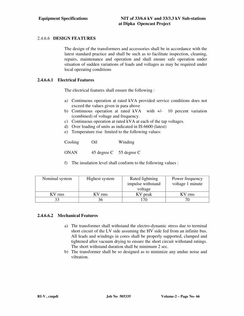
Equipment Specifications NIT of 33/6.6 kV and 33/3.3 kV Sub-stations
at Dipka Opencast Project
RI-V , cmpdi Job No 505335 Volume-2 – Page No- 66
2.4.6.6 DESIGN FEATURES
The design of the transformers and accessories shall be in accordance with the
latest standard practice and shall be such as to facilitate inspection, cleaning,
repairs, maintenance and operation and shall ensure safe operation under
situation of sudden variations of loads and voltages as may be required under
local operating conditions
2.4.6.6.1 Electrical Features
The electrical features shall ensure the following :
a) Continuous operation at rated kVA provided service conditions does not
exceed the values given in para above
b) Continuous operation at rated kVA with +/- 10 percent variation
(combined) of voltage and frequency.
c) Continuous operation at rated kVA at each of the tap voltages.
d) Over loading of units as indicated in IS:6600 (latest)
e) Temperature rise limited to the following values:
Cooling Oil Winding
ONAN 45 degree C 55 degree C
f) The insulation level shall conform to the following values :
Nominal system Highest system Rated lightning
impulse withstand
voltage
Power frequency
voltage 1 minute
KV rms KV rms KV peak KV rms
33 36 170 70
2.4.6.6.2 Mechanical Features
a) Thr transformer shall withstand the electro-dynamic stress due to terminal
short circuit of the LV side assuming the HV side fed from an infinite bus.
All leads and windings in cores shall be properly supported, clamped and
tightened after vacuum drying to ensure the short circuit withstand ratings.
The short withstand duration shall be minimum 2 sec.
b) The transformer shall be so designed as to minimize any undue noise and
vibration.
Equipment Specifications NIT of 33/6.6 kV and 33/3.3 kV Sub-stations
at Dipka Opencast Project
RI-V , cmpdi Job No 505335 Volume-2 – Page No- 67
2.4.6.7 Constructional Details
2.4.6.7.1 Core
a) The transformer core shall be made of high grade non-ageing grain oriented
cold rolled silicon steel sheets of low hysterisis loss and high permeability.
The core structure shall be securely grounded to prevent electrostatic
potential. Lifting eyes and lugs shall be provided on the limbs and co8ils
assembly. Preferably no bolt shall be used in the cores. Clamping shall be
done externally to the limb.
b) The design of the magnetic circuit shall be such as to avoid static
discharges, development of short circuit paths within itself or to the earthed
clamping structure and the production of flux component at right angles to
the plane of lamination which may cause local heating.
c) Cores and windings shall be capable of withstanding shock during transport,
installation & service and adequate provision shall be made to prevent
movement of core and winding relative to tank during these conditions.
d) All steel sections used for supporting the core shall be thoroughly sand
blasted after cutting, drilling and welding.
e) The manufacture shall furnish the details such as type of core material,
source of procurement and BH curve & design flux density at normal tap.
2.4.6.7.2 Tanks
a) Tanks shall be welded construction and fabricated from boiler steel plates of
adequate thickness. The weld procedure and performance shall be in line with
ASME BPV-IX.
b) All seams and joints those are not required to be opened at site shall be factory
welded and wherever possible they shall be double welded.
c) Tanks stiffeners shall be provided for general rigidity and these shall be designed
to prevent retention of water.
d) The tanks shall be designed to withstand:
i) Mechanical shocks during transportation
ii) Vacuum filling of oil
iii) Short circuit force
e) The transformer tank and its accessories shall be designed without pockets
wherein gas may collect.
f) Adequate space shalla be provided at the bottom of the tank for settlements of
sediments
g) Suitable guides shall be provided in the tank for positioning the core and coil
assembly.
h) The tank shall be suitable for movement in both directions during shipment. Each
tank shall be provided with
i) Lifting lugs suitable for lifting the complete transformer
j) A minimum of four jacking pads.
Equipment Specifications NIT of 33/6.6 kV and 33/3.3 kV Sub-stations
at Dipka Opencast Project
RI-V , cmpdi Job No 505335 Volume-2 – Page No- 68
2.4.6.7.3Tank Cover
a) The tank cover shall be sloped to prevent retention of rain water and shall not
distort when lifted.
b) At least two adequately sized inspection covers one at each end of the tank shall
be provided for easy access to bushings and earth connection. The inspection
covers shall have suitable lifting arrangement.
c) The tank covers shall be fitted with thermometer pockets (in the position of
maximum oil temperature) for bulbs of oil and winding temperature indicators.
The thermometer pocket shall be fitted with captive screwed top to prevent ingress
of water. It shall be possible to remove these bulbs without lowering the oil in the
tank.
d) Bushings, turrets, inspection covers, thermometer pockets etc. shall be designed to
prevent ingress of water into or leakage of oil from the tank.
e) All bolted connections shall be fitted with weather proof hot oil resistant neoprene
gasket in between for complete oil tightness. If gasket is compressible metallic
stop shall be provided to prevent over compression.
2.4.6.7.4 Mounting Arrangement
a) The transformers shall be provided with two nos. bi-directional skids and pulling
eyes integral with the tank body for fixing the transformer tank on foundation.
b) These skids shall be such that the bottom of the tank is at a sufficient height above
foundation for cleaning purposes. Each transformer shall be provided with
unit/bi-directional, flat/flanged rollers of suitable length.
2.4.6.7.5 Conservator Tank
a) The conservator tank shall have adequate capacity to accommodate oil
preservation system and volumetric expansion of the total cold oil volume in
the transformer and radiators for a change in temperature from minimum
ambient air temperature of 5 degree centigrade to 110 degree centigrade.
b) The conservator shall be bolted into position so that it can be removed for
cleaning purposes.
c) The conservator tank, shall be fitted with a silica gel filter breather
d) The conservator shall be fitted with magnetic oil level gauge with two
independent low level electrically insulated alarm and trip contracts. The oil
level at 30 degree centigrade shall be marked on the gauge.
2.4.6.7.6 Pressure Relief Device
a) The transformers shall be provided with the single diaphragm type of explosion
vent and a spring loaded pressure relief device.
b) An equalizer pipe shall be connected to explosion vent from the conservator.
c) The pressure relief device shall be sufficient size for rapid release of any pressure
that may be generated in the tank. The device shall operate at a static pressure than
the hydraulic test pressure of transformer tank. Means shall be provided to
prevent ingress of rain water. An extension pipe fitted above the device shall
Equipment Specifications NIT of 33/6.6 kV and 33/3.3 kV Sub-stations
at Dipka Opencast Project
RI-V , cmpdi Job No 505335 Volume-2 – Page No- 69
direct the major flow of ejected oil downwards and permit its removal without
disturbing the device.
2.4.6.7.7 Buchholz Relay
A double float type Bushholz relay shall be provided. All gas evolved in the
transformer shall be collected in this relay.The relay shall be provided with a test cock
suitable for a flexible pipe connection for checking its operation. A valve shall be
provided for a connection to gas collector to facilitate gas sampling with the
transformer in service. The Buchholz relays shall be provided with two electrically
independent underground contacts, one for alarm on gas accumulation, and the other
for tripping on sudden rise of pressure.
2.4.6.7.8 Temperature Indicator
(a)Oil temperature Indicator (OTI)
The transformers will be provided with a 150 mm dial type thermometer for top oil
temperature indication. The thermometer shall have adjustable, potential free alarm
and trip contacts, maximum reading pointer and resetting device and shall be mounted
in the marshalling box. A temperature sensing element suitably located in a pocket in
the top oil shall be furnished. This shall be connected to the OTI by means of capacity
tubing. Accuracy class of OTI shall be 2 degree centigrade or better. The OTI shall
have full scale detection of at least 240 degree centigrade and shall have linear
graduation to read every 2 degree centigrade.
(b) Winding Temperature Indicator (WTI)
A device for measuring the hot spot temperature of the winding shall be provided.
The accuracy class of winding temperature indicator shall be +/- 2 degree centigracde
or better. It shall comprise the following:
i) Temperature sensing element.
ii) Image coiled and bushing current transformer.
iii) Auxiliary CTs if required to match the image coil, shall be furnished
and mounted in the marshalling box.
iv) 150 mm local indicating instrument with max. reading pointer mounted
in marshalling box. It shall have two adjustable potential free contacts,
one for winding temp. high alarm and one for trip, in addition to the
contacts required for control of cooling equipment.
v) Automatic ambient temp. compensation.
vi) All contracts shall be adjustable on a scale and suitable for connection
in 240 V circuit. These shall be accessible on removal of the cover.
vii) The WTI shall have a full scale deflection of at least 240 centigrade
and shall have linear graduations to read every 2 degree centigrade.
Equipment Specifications NIT of 33/6.6 kV and 33/3.3 kV Sub-stations
at Dipka Opencast Project
RI-V , cmpdi Job No 505335 Volume-2 – Page No- 70
2.4.6.7.9 Windings
a) The conductors shall be electrolytic grade copper free from scales and burns.
b) All windings shall be fully insulated. No graded insulation shall be accepted. Use of
enamel as a sole conductor insulation is prohibited.
c) The insulation of transformer windings and connections shall be free from insulating
compounds which are liable to soften, ooze out, shrink or collapse and be non
catalytic and chemically inert in transformer oil during service.
d) Coil assembly and insulating spacers shall be so arranged as to ensure free circulation
of oil and to reduce the hot spot of the winding.
e) Tapings shall be so arranged as to preserve the magnetic balance of transformers at all
voltage ratios.
f) The maximum fault level to which the transformers may be subjected is 750 MVA,.
Transformers manufacturer may take this aspect into account while designing the
transformer for the through fault withstand capability.
g) All bus bars and leads shall be adequately supported in insulated cleats or frames from
the clamping locked.
h) The studs, set screws or bolts provided for securing cleats or frames shall be
effectively locked.
i) Bus bars and leads shall be supported throughout their length to ensure that they do
not move under normal service or during transport or are not forced out from the
prescribed position during any short circuit.
j) The impedance values shall be as per annexure-I.
k) The winding shall be connected to achieve a Vector group of DY11.
2.4.6.7.10 Insulation Materials
a) Class ‘A’ insulating materials specified in IS:1271 shall be used Wood insulation,
b) Insulating Oil
i) The new insulating oil supplied with the transformer shall conform to the
requirements of IS:335. No inhibitors shall be used in the oil
ii) Prior to filling the oil in the main tank suitable number of samples shall be tested
for BDV, moisture content, resistivity at 90 deg. C, tan delta at 90 deg. C and
interfacial tension. The oil samples taken from the transformer at site shall
conform to the requirements of IS:1866.
iii) The manufacturer shall dispatch the transformer filled with oil.
Ten percent (10%) extra oil shall be supplied for topping up, in non returnable sealed
containers suitable for outdoor storage.
2.4.6.7.11Earthing Terminals
Two earthing terminals suitable for connecting 50 x 8 mm mild steel flat shall be
provided at positions close to the two diagonally opposite bottom corners of tank.
These grounding terminals shall be suitable for bolted connection. Two earthing
terminals shall also be provided on marshalling box and any other equipment mounted
separately.
Equipment Specifications NIT of 33/6.6 kV and 33/3.3 kV Sub-stations
at Dipka Opencast Project
RI-V , cmpdi Job No 505335 Volume-2 – Page No- 71
2.4.6.7.12 Oil Preservation System
a) The transformer shall be provided with conservator preservation system. The
top of the conservator shall be fitted with a silica get filter breather. It shall be
so designed that:
i) Passage of air is through dust filter and silica gel.
ii) Silica gel is isolated from atmosphere an oil seal.
iii) Moisture absorption indicated by a change in colour of the tinted crystal
can easily observed from a distance.
iv) Breather shall be mounted not less than 1400 mm above rail top level.
2.4.6.7.13Terminal Arrangement
a) Porcelain Bushing
i) The minimum clearances in air between the phases and between the phase and
earth potential of the porcelain bushing shall be in accordance with IS:2026-Part
V.
ii) Bushing terminals shall be provided with suitable terminal connectors of approved
type and size of ACSR/aluminium tubular conductors.
iii) All transformers bushing shall be of solid porcelain with rain sheds conforming to
IS:8603.
iv) The removal of bushing shall be possible without disturbing the current
transformers, secondary terminals and connectors or pipe work.
b) Cable Boxes and disconnecting Chambers
i) Wherever cable, connections are specified suitable air insulated type cable boxes
of sufficient sizes shall be provided to accommodate cable termination. Cable
boxes shall be designed and installed such that it shall be possible to move away
the transformer without disturbing the cable termination leaving the cable box on
external supports. The support for the cable box shall be of galvanized iron
ii) Cable boxes shall have terminal connectors of adequate size and bolt hoes to
receive cable lugs.
iii) The bidder shall provide earthing terminals on the cable box to suit 50 x 8 mm GI
flat.
iv) All necessary cable terminating accessories such as supporting brackets, power
cable lugs, hard ware etc. shall be provided by the bidder.
v) Cable boxes shall have removable top cover and ample clearance shall be
provided to enable either transformer or each cable to be subjected separately to
high voltage test.
vi) Cable boxes shall have degree of protection of IP-52 as per IS:2147.
Equipment Specifications NIT of 33/6.6 kV and 33/3.3 kV Sub-stations
at Dipka Opencast Project
RI-V , cmpdi Job No 505335 Volume-2 – Page No- 72
2.4.6.7.14 Current Transformers
a) Bushing CTs shall be provided. It shall be possible to remove the turret
mounted CTs from the transformer tank without removing the tank cover.
b) The current transformers shall commonly with IS:2705
c) All secondary leads of bushings mounted CTs shall be brought to a terminal
box gear each bushing and then wired up to transformer marshalling box. The
CTs terminals shall have shorting facility
2.4.6.7.15 Terminal Marking
The terminal marking and their physical position shall be in accordance with IS:2026
2.4.6.7.16 Termination Arrangement for Neutrals
a) The transformer shall be restricted earthed at the secondary neutral.
b) The neutral terminal brought on to a separate neutral bushing shall be
connected to associated neutral grounding pit by a neutral grounding resistor.
2.4.6.7.17 Tap Changer:
The 16MVA transformer shall be provided with an on-load tap changer having a
range of + 10% to – 10% with 16 steps of 1.25% each. The tap changer shall be
effectively designed for remote electrical, local electrical and local manual operation
as per requirement. The 5 MVA transformer shall be provided with an off-load tap
changer having a range of + 10% to – 10% with 16 steps of 1.25% each. The tap
changer shall be effectively designed for local manual operation.
ii) The tap changer shall include the following:-
a) Oil immersed tap selector and arcing switch provided with resistor.
b) Motor operated mechanism for on load tap changer.
c) Control and protection device.
d) Local normal operating device.
e) Local tap changer position indicator.
iii) The tap changer shall be designed such that the contacts do not interrupt
arcs within the main tank of the transformer. The oil filled compartment of
tap selector switch shall be provided with means of releasing the gas produced
due to arcing. It shall be designed so as to prevent the oil of tap selector
compartment from mixing with the oil of the transformer compartment and
also from mixing with the oil of the transformer tank. Operating mechanism
Equipment Specifications NIT of 33/6.6 kV and 33/3.3 kV Sub-stations
at Dipka Opencast Project
RI-V , cmpdi Job No 505335 Volume-2 – Page No- 73
of OLTC shall be designed such that only one step is actuated by each
command and subsequent step shall be actuated by new or repeat command.
iv)The transformer shall give full load output at all taps. The tap changer shall
be provided with out of step protection.
v) The following accessories shall be provided with tap changer as per
requirement:
1. Raise and lower push button (remote).
2. Tap position indicator (remote)
3. Indication lamp showing tap changing is in progress.
4. Motor starter contactor with O/L and single phasing protection.
5. Contactor for forward and reverse.
6. Raise/lower operation on local electrical control.
7. Raise//lower limit switches.
8. Anti condensation heater with switch.
9. Provision and accessories for local manual operation.
10. Interlock between manual and electrical operation.
11. Tap position indicator, mechanical.
12. Operation counter
2.4.6.7.18 Radiators
The radiator shall be detachable type, mounted on the tank. Each radiator shall be
provided with the following.
a) A drain valve at the bottom.
b) An air release plug at the top.
c) Shut off valve at each point of connection to the tank. The location and
configuration of radiators shall be subject to purchaser approval.
2.4.6.7.19 Marshalling Box
a) A sheet weather, vermin and dust proof marshalling box shall be provided with
each transformer to accommodate.
Equipment Specifications NIT of 33/6.6 kV and 33/3.3 kV Sub-stations
at Dipka Opencast Project
RI-V , cmpdi Job No 505335 Volume-2 – Page No- 74
i) Temperature indicators
ii) Terminal blocks for incoming and outgoing cables
b) The sheet steel used shall be at least 2.0 mm thick. The box shall be free standing
floor mounted type with a sloping proof. The degree of protection shall be IP 53
in accordance with IS:2147.
c) The temperature indicators shall be so mounted that the dials are naot more than
1600 mm from ground level.
d) The marshalling box shall have glazed door of suitable size for convenience of
temperature indicators readings.
e) All cables shall enter the kiosk from the bottom and the gland plate shall be not
less than 450 mm from the base of the box. The gland plate and the associated
compartment shall be sealed in suitable manner to prevent the ingress of moisture,
rodents, insects etc. from the cable trench. Gland plates, cable lugs, cable lugs,
cable glands, etc. shall be provided.
f) The marshalling box shall be supplied with space heater and cubicle lighting with
ON-OFF switches and associated fuses .
g) It shall be located in such a way that, the front shall ot face the transformer. It
shall be mounted at least 500 mm above the ground level.
h) The gland plate shall be made into two detachable halves, for facilitating
termination of incoming and outgoing cables separately.
2.4.6.7.20 Painting
The internal and external surfaces including oil filled chambers and structural work to
be painted shall be sand blasted to remove all rust and scale or foreign adhering
matter. All steel surfaces in contact with insulating oil shall be painted with two coats
of heat resistant, oil insoluble, insulating varnish. All steel surface exposed to
weather shall be given a primary coat of zinc chromate, second coat of oil and
weather resistant varnish of a colour distinct from primary. At least two coats of
flossy oil and weather resisting non facing paint of light grey colour corresponding to
shade no. 631 of IS:5. Primary paint shall be as per IS:104 and intermediate and final
coat of paint shall be as per IS:2932.
2.4.6.7.21 Bolts and Nuts
All bolts and nuts exposed to weather shall be of hot dip galvanized or cadmium plate
or zinc passivated steel. All bolts, nuts and washers in contact with non ferrous part
which carry current shall be of phosphor bronze.
2.4.6.7.22 Control wiring
a) All control, alarms, indicating and relaying devices provided with the
transformer shall be wired by the bidder up to the terminal blocks inside
the marshalling box. The bidder shall supply and install the required 1100
V grade heavy duty PVC insulated steel wire armoured, PVC sheathed,
multi core cables with copper conductors of the least 2.5 sq mm
conforming to IS:1554. The cables shall be properly supported.
Equipment Specifications NIT of 33/6.6 kV and 33/3.3 kV Sub-stations
at Dipka Opencast Project
RI-V , cmpdi Job No 505335 Volume-2 – Page No- 75
b) All devices and terminal blocks within the marshalling box shall be clearly
identified by symbols corresponding to those used on applicable schematic
or wiring diagrams.
c) Not more than two (2) wires shall be connected to one terminal. At least
20% spare terminals shall be provided. Each terminal shall be suitable for
connecting two numbers 2.5 sq.mm stranded copper conductor from each
side.
d) Terminal blocks fittings shall be provided with all the transformers.
2.4.6.7.23 Fittings
The following fittings shall be fitted with each transformer:
i) Oil conservator with oil level gauge, drain valve and filling holes
with air tight cap.
ii) On load tap changer for 16 MVA Transformer and off load for 5
MVA Transformer.
iii) Silica gel breather (Dehydrating breather)
iv) Explosion/Relief vent with double diaphragm equaliser connection.
v) Double float Bucholz relay with valves for two sides and with
potential free alarm and trip contacts wired up to the marshalling box.
The approach facility and inspection facility should be provided for
Bucholz relay with live transformer.
vi) Oil sampling device for the tank top and bottom oil sampling with
valves.
vii) Magnetic oil level gauge/indicator with low oil level alarm
contacts.
viii) One number dial type thermometer of suitable size with maximum
reading pointer and adjustable potential free contacts for alarm and trip
for top oil temperature.
ix) One set of winding temperature measuring device with RTDs
embedded in winding (2 nos. per phase).
x) Additional pockets for mercury-in-glass thermometer for measuring
oil and winding temperature.
xi) Rating and diagram plates and terminal marking plate.
xii) Identification marking plate.
Equipment Specifications NIT of 33/6.6 kV and 33/3.3 kV Sub-stations
at Dipka Opencast Project
RI-V , cmpdi Job No 505335 Volume-2 – Page No- 76
xiii) Marshalling box mounted on the transformer, weather proof and
suitable for outdoor mounting, housing control and signaling
equipment for AF cooling fans, oil motors and terminal connection for
various alarm and trip circuits etc. provided in the transformer. A
heater shall be provided inside the marshalling box to avoid any
condensation.
xiv) Under carriage suitable for moving on a suitable rail track, The
under carriage shall be mounted on required number of single flanged
CI/CS wheels with axils.
xv) Under carriage suitable with jacking pads and with hauling
holes/hook.
xvi) Lifting lugs for the cover.
xvii) Lifting/jacking lugs for core and winding.
xviii) Lifting lugs and transport lugs for the complete transformer.
xix) Air release device and plugs at the top of the transformer and
busing turrets.
xx) Supervisory alarm and trip contacts for oil temperature indicator.
xxi) Supervisory alarm and trip contacts for winding temperature
indicator.
xxii) Supervisory alarm and trip contacts for gas operated double float
relay.
xxiii) Supervisory alarm contacts for oil level indicator.
xxiv) Drain valve with plug for the transformer tank.
xxv) Inspection cover.
xxvi) 33 kV and 6.6/3.3 kV bushings (condenser bushing)
xxvii) 33 kV and 6.6/3.3 kV neutral bushings.
xxviii) Oil filling hole and cap.
xxix) Filter valves.
xxx) First filling of transformer oil as per IS 335.
Equipment Specifications NIT of 33/6.6 kV and 33/3.3 kV Sub-stations
at Dipka Opencast Project
RI-V , cmpdi Job No 505335 Volume-2 – Page No- 77
2.4.6.8 Performance
a) Operating conditions
i) The transformers shall be capable of being loaded in accordance with IS:6600
up to load of 15%. There shall be no limitation imposed by bushing, tap changer
etc.
ii)The transformers shall be capable of being continuously without danger on any
taping at the rated KVA with voltage variation of +/- 10% corresponding to the
voltage of the taping
iii) For consideration of specific loading, the transformer shall be suitable for
continuous operation for flux densities of 1.1 to 1.9 weber per sq.m.
b) Fault Conditions
i) The transformer and all accessories including CTs shall be capable for
withstanding any external short circuit at bushing terminal without damage for
two (2) weber per sq.m.
ii) The maximum flux density in any part of the cores and yoke at normal voltage
and frequency shall not exceed 1.9 wb per sq.m.
c) Impedance
2.4.6.9 Inspection
The manufacturer shall carry out a comprehensive inspection and testing program
during manufacture for all bought out items li8ke the core material and also
workmanship during this stage. The manufacturer shall submit the inspection
program at least four weeks prior to the purchaser. The inspection shall cover but not
be limited to the following :
a) Tank and Accessories
i) Physical and dimensional check of the tank and its accessories.
ii) Weld procedure
iii) Crack detection of welds dye penetration test
b) Core
a) Sample core material for specific loss, bend properties, magnetization
characteristic and thickness
b) Quality of varnish used on the stampings.
c) Inter-laminar insulation between core sections before and after pressing
d) Assembled core material for measurement of iro loss and for any hot spot
by exciting the core at the pre-designed value of flux density.
c) Insulating Material
Equipment Specifications NIT of 33/6.6 kV and 33/3.3 kV Sub-stations
at Dipka Opencast Project
RI-V , cmpdi Job No 505335 Volume-2 – Page No- 78
i) Physical and electrical properties of material as per relevant IS.
ii) Dielectric strength
iii) Reaction of hot oil on insulating material
d) Winding
Paper insulated winding conductor for mechanical properties and electrical
proper ties as per relevant IS.
e) Assembled Transformer
Provision of all fittings and accessories on the assembled unit as per approved
general arrangement drawing
f) Pre Shipment checks at manufacturer’s works
i) Proper packing and preservation of accessories like radiators, bushings,
explosion vent, dehydrating, breather, connecting pipes, conservator
etc.
ii) Proper bracing to arrest the movement of the core winding assembly
inside the tank
iii) Leakage test
2.4.6.10 Tests
i) In accordance with requirement of IS:2026 and any latest revision
thereof the routine test, type test supplementary test shall be carried out
in order to ensure their being electrically and mechanically sound in
every respect and also to meet the guaranteed performance. All tests,
as stipulated in IS: 2026 shall be carried out by the Contractor in the
presence of Employer’s representative without any extra cost to the
Employer.
ii) Routine Tests
The transformer shall be subjected to routine tests at the
manufacturer’s works. The routine tests shall comprise –
a) Measurement of winding resistance
b) Measurement of voltage ratio and check of voltage vector
relationship
c) Measurement of impedance voltage/short circuit impedance
(principal tapping) and load loss.
d) Measurement of no-load loss and current.
e) Measurement of insulation resistance.
f) Dielectric tests
g) Tests on on-load tap-changers
h) Induced over-voltage withstand
Equipment Specifications NIT of 33/6.6 kV and 33/3.3 kV Sub-stations
at Dipka Opencast Project
RI-V , cmpdi Job No 505335 Volume-2 – Page No- 79
iii) Type Tests
In case the transformer is representative of one being purchased and
the test certificates furnished are of the representative one, the
Purchaser may accept these as evidence of type test instead of actual
tests. The type tests are as below:
a) Impulse voltage withstand test
b) Temperature rise test
c)Measurement of voltage ratio and check of voltage vector
relationship
d) Short circuit test
e) Measurement of insulation resistance
f) Dielectric tests
g) Temperature rise test
iv) Carrying out type test of the transformer and submission of type
test certificate will be the sole responsibility of the Contractor.
v) Special Tests
The following test shall be carried out at the manufacturer’s works as
per relevant standards:
a) Measurement of zero-sequence impedance
b) Short circuit test.
c) Measurement of acoustic noise level
d) Measurement of harmonics of no-load current.
e) Measure of power consumption by fans.
f ) Tan delta test
g) Oil leakage test on transformer oil tank
vi) Tests on Tap-changer
The tap-changer shall be subjected to tests as specified in IS: 2026 (Part-I) and
IS: 8468 (with amendment no. 1)
2.4.6.11 IS to be followed (with latest amendment):
a) IS: 2026 Specification for power transformers
b) IS: 335 Insulation oil for Transformer and switchgear
c) IS: 3347 Dimensions of Porcelain Transformer Bushings
d) IS: 2099 Specification for High Voltage Porcelain
Bushings
Equipment Specifications NIT of 33/6.6 kV and 33/3.3 kV Sub-stations
at Dipka Opencast Project
RI-V , cmpdi Job No 505335 Volume-2 – Page No- 80
e) IS: 3639 Fittings and Accessories for Power
Transformers
f) IS: 8468 On load tap changers
g) IS: 4257 Dimensions for clamping arrangements for
Bushings
h) IS: 2165 Insulation co-ordination guide
i) Indian Electricity Rules, 1956(with latest amendments)
j) IS 3401 Silica gel
k) The transformer shall be manufactured and conform to IS:2026 or
latest revision thereof.
2.4.6.12 Test Certificate
i) Manufacturer’s test certificate of all tests on transformer shall be provided
by the Contractor.
ii) All the details as per Schedule of this volume should be duly filled in and
submitted along with the offer.
Equipment Specifications NIT of 33/6.6 kV and 33/3.3 kV Sub-stations
at Dipka Opencast Project
RI-V , cmpdi Job No 505335 Volume-2 – Page No- 81
2.4.7.0 SPECIFICATIONS FOR NEUTRAL GROUNDING RESISTER (NGR)
( One no. for each Power Transformer has already been supplied but
without instantaneous earth fault relay and CT for NGR)
The neutral grounding resistance shall be used to ground the neutral of
secondary windings of both 5 MVA and 16 MVA transformers to limit earth
fault current to 50 Amps along with the following components as per IER
116(I):
i) Neutral Grounding resistance(unbreakable) non-magnetic type resister
Grade- 38 ohms(for 3.3 kV side) and 76 ohms(for 6.6 kV side) having
adequate power for rated current of 50 Amp with temperature rise of 350
degree centigrade.
ii) Fail safe type ground fault and Neutral Grounding Resistance (NGR)
Monitoring relay with current sensing range from 1 Amp to 50 Amp for both
3.3 kV and 6.6 kV systems with all suitable arrangement for operation.
iii) Ground fault and NGR monitoring relay.
The monitoring parameters for fault tripping are as follows:
a) Neutral grounding resistance failure (less than 70% and more than 150%)
b) Neutral/Ground open circuit
c) Sensor failure
d) Phase to earth fault
e) Continuous monitoring of NGR and provision for locking arrangement in
case of tripping of breaker due to above fault.
The other provisions for the above system shall be as follows:
a) Alarm and trip signal for any type of failure of NGR
b) Real time two digit display of Neutral to ground current in Amps and
Neutral Voltage in kV
c) Trip time delay with adjustable push button keys
d) LED fault indication for NGR fault trip, Ground fault trip and Sensor fault
trip
e) Test/Reset provision
Equipment Specifications NIT of 33/6.6 kV and 33/3.3 kV Sub-stations
at Dipka Opencast Project
RI-V , cmpdi Job No 505335 Volume-2 – Page No- 82
The Supplier should be responsible for supply, installation, commissioning
and testing
The neutral grounding resister shall confirm to the following specifications:
1) System Voltage : 6.6 kV /3.3 kV as per requirement
2) Location : Outdoor
3) Resistance element : Stainless steel wire wound, supported
on cast resin mica insulators
4)Time Rating : 10 seconds
5) Rated Resistance and Power : Suitable to limit the earth fault current
to 50 Amps
6) Enclosure : The resistance elements shall be
covered with sheet steel enclosure and
shall be protected against entry of dust
and moisture. The enclosure shall be
provided with lifting hooks, louvers, dust
catchers etc.
7) Degree of Protection : IP-33 (minimum) of enclosure
8) Connections : The external connections shall be made
through the bushings.
9) Mountings : The neutral grounding resistance shall
be mounted on structures. Provision shall
be kept for providing earth fault
protection CT at the ground end of the
resistance.
Equipment Specifications NIT of 33/6.6 kV and 33/3.3 kV Sub-stations
at Dipka Opencast Project
RI-V , cmpdi Job No 505335 Volume-2 – Page No- 83
2.4.8.0 SPECIFICATIONS FOR CAPACITOR BANK
2.4.8.1 This specification covers requirements for 6.6 kV and 3.3 kV shunt capacitor
banks suitable for indoor installation.
The capacitor banks shall comply with the latest version of IS: 2834 and IEC-831-1
& 831-2 except where modified or extended by the provision of this specification and
with the relevant parts of standards mentioned in clause 2.4.8.2
2.4.8.2 OTHER RELEVANT STANDARDS
The other relevant Indian Standards are as under:
IS : 12672 Internal fuses and internal over pressure disconnectors for shunt capacitors
IS : 9046 A.C. contactors of voltages above 1000 V up to and including 11000V
IS : 13118 General requirements for circuit breakers for voltages above 1000V
IS : 9920 Switches and switch isolators for voltages above 1000 V
IS : 13947 L.V. switch gear and control gear (Part 4 section 1- contactors)
IS : 13947 L.V. switch gear and control gear (Part 3 - switches)
IS : 13947 L.V. switch gear and control gear (Part 2 - circuit breakers)
IS : 9402 High voltage fuses for the external protection of shunt capacitors
IS : 13703 L.V. Fuses for voltages not exceeding 1000V A.C.
IS : 3043 Code of practice for earthing
2.4.8.3 DESIGN
The capacitor units shall be designed for the following :
(a) Watt losses not more than 0.5 kW per kVAR
(b) Temperature withstand category of 550 C
(c) Output (kVAR) tolerance not exceeding 10 %
(d) Capacitor - fuse co-ordination to reduce risk of tank rupture
(e) Use of bio degradable eco friendly dielectric compound
(f) Switching life not less than 60,000 operations
2.4.8.4 CONSTRUCTION
2.4.8.4.1 The basic units shall be made of suitable material for better heat dissipation
and lower operating temperature.
2.4.8.4.2 The basic units shall be insulated for power frequency withstand voltages.
2.4.8.4.3 Each unit shall be supplied in a suitable container.
2.4.8.4.4 Each element of capacitor unit shall have its own built in special fuse. In case
of fault in an element, the over voltage on the remaining elements shall not
exceed 10%. Internal discharge resistance shall be provided to limit the
residual voltage to less than 50 volt as per relevant standard.
2.4.8.4.5.1 The capacitor banks shall be designed to withstand electro-dynamic and
thermal stresses caused by transient over currents during switching.
Equipment Specifications NIT of 33/6.6 kV and 33/3.3 kV Sub-stations
at Dipka Opencast Project
RI-V , cmpdi Job No 505335 Volume-2 – Page No- 84
2.4.8.5.0 PERFORMANCE
The Capacitor Banks shall be grouped in different kVAR rating, which shall be
switched ON/OFF as required according to load connected. For this purpose capacitor
kVAR shall be subdivided into a number of regulating stages.
2.4.8.6.0 APFC Panel
The APFC Panel shall be dust tight vermin proof sheet metal enclosed cubicle
suitable for floor mounting. The regulating stages of required Capacitor Banks shall
be switched ON/OFF by means of suitable relay to ensure the system power factor to
0.98 lagging. To eliminate unduly frequent switching when peak load of short
duration occur a time delay relay shall be incorporated for stage to stage switching.
All internal wiring for control sensing instruments, relays etc. shall be done with
650V grade, PVC insulated copper conductor of size not less than 2.5 mm2. The
capacitor bank shall be rated for continuous operation and shall be suitable for indoor
installation.
2.4.8.7.0 TECHNICAL SPECIFICATION
1. Applicable Standard : IS : 2834
2. System : 3300 / 6600 volts, 3 phase 50 Hz
restricted earthed system
3. Location :
4. No. of phases : Three
5. Connection : Star/Delta
6. Output kVAR : As required
7. Insulation level : As per relevant IS
8. Overload
: 1.3 times rated current continuously
9. Losses : Less or equal to 0.5 W/ kVAR
10. Output tolerance : 10 % (Max)
11. Inrush Current : Not exceeding 100 times rated current
12. Peripherals to be supplied : Discharge resistors, HRC Fuse, Racks,
Isolators
13. Accessories (Optional) : Control Panel with Automatic P.F.
Correction relay
14. Discharge device : Discharge Resistor
Equipment Specifications NIT of 33/6.6 kV and 33/3.3 kV Sub-stations
at Dipka Opencast Project
RI-V , cmpdi Job No 505335 Volume-2 – Page No- 85
2.4.9.0 SPECIFICATIONS OF 3300/6600 VOLT SWITCHBOARD
This specification covers the requirements for 6.6/3.3 kV switch boards incorporating
vacuum circuit breakers and vacuum contactors units or any combination of these.
2.4.9.1 The boards shall comply with the latest version of IS 8623 & IEC 439-1 except where
modified or extended by this specification and with the relevant parts of standards
mentioned in clause 2.4.9.2
2.4.9.2 OTHER RELEVANT STANDARDS
The other relevant standards applicable are as under:
IS : 13118 General requirements for circuit breakers for voltages above 1000V
IS :13947 LV switch gear and control gear
IS :10118 Code of practice for selection, installation and maintenance of
switchgear and control gear
IS :4237 General Requirements for Switchgear and Control gear for voltages
not exceeding 1000 V.
IS :6875 Switches and push-buttons
IS :13703 LV fuses for voltages not exceeding 1000 V AC
IS :12021 Specification of control transformers
IS :2705 Current Transformers
IS :3156 Voltage Transformers
IS :11353 Guide for uniform system of marking and identification of conductors
and apparatus terminals
IS :2147 Degree of protection provided by enclosures for low voltage
switchgear and Control gear
IS :3043 Code of practice for earthing
IS :6005 Code of practice of phosphating iron and steel.
S :3202 Code of practice for climate proofing of electrical equipment
IS :2629 Hot dip galvanising
IS :5082 Wrought Aluminium and Aluminium alloys for electrical purposes
IS :722 A C Electricity Meters
IS :1248 Electrical Indicating instruments
IS :3231 Electrical relays for power system protection
IS :5 Colours for ready-mixed paints and enamels.
IS :1554 PVC insulated cables for working voltages up to and including 1100V
IS :2551 Danger Notice Plates
Equipment Specifications NIT of 33/6.6 kV and 33/3.3 kV Sub-stations
at Dipka Opencast Project
RI-V , cmpdi Job No 505335 Volume-2 – Page No- 86
2.4.9.3.0 DESIGN
2.4.9.3.1 Electrical
The boards shall be designed to ensure the following :
(i) Continuous operation at rated capacity at service condition mentioned before
(ii) Capacity to withstand fault level mentioned before
(iii) Capacity to withstand power frequency voltage mentioned in annexure I
2.4.9.3.2 Mechanical
The boards shall be designed to ensure the following :
(i) Ready interchangeability of components
(ii) Easy accessibility to components for inspection & maintenance.
2.4.9.4.0 CONSTRUCTION
2.4.9.4.1 The board shall comprise single front panel / panels metal enclosed, dust &
vermin proof floor mounted, free standing type. The panels shall be fabricated from
sheet steel of minimum thickness 2.5 mm for load bearing members, 2 mm for front
metering doors and 1.6 mm for side covers, rear doors and partition sheets.. Stiffeners
shall be provided wherever necessary. The thickness of gland plates shall not be less
than 3.0 mm for hot/cold rolled steel sheets and not less than 4.0 mm for non-
magnetic material.
2.4.9.4.2 The panels shall be provided with a degree of protection IP 4X. All cutouts shall
be provided with synthetic rubber gaskets.
2.4.9.4.3 The panels shall be of uniform height.
2.4.9.4.4 The board shall be easily extendable on both sides by the addition of panels after
removing the end covers.
2.4.9.4.5 A panel incorporating a breaker or an isolator or a change over contactor or a
control transformer shall meet the following requirements:
a) Epoxy coated busbars of required section shall be provided in all panels mounted on
stable & strong supports to withstand thermal and electromagnetic forces during fault
conditions.
b) Epoxy resin insulated PT & CT shall be provided in a breaker panel suitably mounted
with detachable devices for withdrawal or plugging in.
c) Epoxy resin insulated control transformers shall be provided in a control power
supply panel suitably mounted with detachable devices for withdrawal or plugging in.
d) Draw-out type vacuum circuit breakers of required current rating and rupturing
capacity shall be provided in a breaker panel. The breaker shall be mounted on a
withdraw-able truck with three positions; "SERVICE", "TEST" & "ISOLATED".
e) Fixed type vacuum contactors shall be provided in a change over panel of required
load breaking capacity duly tested at a reputed test house.
Equipment Specifications NIT of 33/6.6 kV and 33/3.3 kV Sub-stations
at Dipka Opencast Project
RI-V , cmpdi Job No 505335 Volume-2 – Page No- 87
f) Fixed type load break switch shall be provided in an isolator panel of required load
breaking capacity duly tested at a reputed test house.
g) Fixed type auxiliary contactors shall be provided in a breaker panel for relays,
interlocks, change over contactors and remote / local operation.
h) Safety shutters with pad locking arrangement shall be provided in a breaker panel
such that it automatically closes the bus spout apertures whenever the truck is
withdrawn.
i) Mechanical interlocks shall be provided in a breaker panel to prevent racking of the
breaker into the SERVICE position from ISOLATED/TEST position with the breaker
closed or the spring charged.
j) Mechanical interlocks shall be provided in a breaker panel to prevent it's withdrawal
from the SERVICE position to ISOLATED/TEST position without tripping the
breaker.
k) Mechanical interlocks shall be provided in a breaker panel to prevent closing of the
breaker in any intermediate position.
l) Draw-out handle provided in a breaker panel shall not be insertible without tripping
the breaker.
m) Definite minimum time inverse current induction over load relay, instantaneous short
circuit relay and earth leakage relay with auxiliary contacts shall be provided in a
breaker panel along with 110 V DC control supply.
o) All components in a panel shall be neatly arranged and easily accessible for operation
and maintenance.
p) In all panels a galvanized steel earth bus shall be provided at the bottom welded./
bolted to it's framework and breaker earthing contact bar.
q) In all panels the earth bus shall have sufficient cross section to carry the short time
fault current to earth, without exceeding the allowable temperature rise.
r) In all panels suitable arrangements shall be made at each end of the earth bus for
bolting to earthing conductors. The earth bus shall project out of the panel ends and
shall have predrilled holes for this connection. All joint splices to earth bus shall be
made through at-least two bolts and taps by proper lug and bolts connection.
s) In all panels all non-current carrying metal work of the panel shall be effectively
bonded to the earth bus. Electrical conductivity of the whole breaker enclosure
framework and truck shall be maintained even after painting.
t) In a breaker panel the truck and breaker frames shall get earthed while being inserted
in the panel and positive earthing of the breaker frame shall be maintained in all
positions, i.e. SERVICE & ISOLATED, as well as the throughout the intermediate
travel.
x) In all panels the instruments shall be compensated for temperature errors and factory
calibrated to directly read the primary quantities. Means shall be provided for zero
adjustment without removing or dismantling the instruments.
Equipment Specifications NIT of 33/6.6 kV and 33/3.3 kV Sub-stations
at Dipka Opencast Project
RI-V , cmpdi Job No 505335 Volume-2 – Page No- 88
z) In a breaker panel the push buttons shall be of spring return, push-to-actuate type. In a
breaker panel the push buttons shall have required number of normally open and
normally closed contact.
The color of the buttons shall be as under:
Green for breaker CLOSE command
Red for breaker OPEN command
Black for all annunciation functions, overload, reset commands
All push buttons in a breaker panel shall be located in such a way that Red push
buttons are always to the left of Green push-buttons.
2.4.9.4.6 INDICATING LAMPS
a) In the breaker panels LED indicating lamps shall be provided. The lamps shall have
escutcheon plates marked with its function wherever necessary.
b) The LED indicators shall be of following colors,
Red for breaker CLOSE
Green for breaker OPEN
White for AUTO TRIP
Blue for all healthy conditions (e.g. control supply, and also for "SPRING
CHARGED")
Amber for all Alarm Conditions (e.g. overload). Also for "SERVICE" and "TEST"
position indications.
2.4.9.4.7 INTERNAL WIRING
a) The board shall be supplied completely wired internally.
b) The auxiliary wiring shall be carried out with 660 V grade, single core, stranded
copper conductor, color coded, and PVC insulated wires. Conductor size shall be 1.5
mm2 (min.) for control circuit wiring and 2.5 mm2 (min.) for CT circuits.
c) Extra flexible wires shall be used for wiring to devices mounted on moving parts such
as hinged doors. The wire bunches from the panel inside to the doors shall be properly
sleeved or taped.
d) All internal wiring terminations shall be made with solder less crimping type tinned
copper lugs which shall firmly grip the conductor or an equally secured method.
Similar lugs shall also be provided at both ends of component to component wiring.
Insulating sleeves shall be provided over the exposed parts of lugs to the extent
possible.
e) Engraved core identification ferrules marked to correspond with panel wiring diagram
shall be fitted at both ends of each wire. The ferrule shall be of self locking type. The
wire identification marking shall be in accordance with relevant code. Red Ferrules
shall be provided on trip circuit wiring.
Equipment Specifications NIT of 33/6.6 kV and 33/3.3 kV Sub-stations
at Dipka Opencast Project
RI-V , cmpdi Job No 505335 Volume-2 – Page No- 89
2.4.9.4.8 CONTROL TERMINAL BLOCKS
a) Control terminal blocks shall be of 650 Volts grade, rated for 10 Amps and in one
piece moulding. It shall be complete with insulating barriers, clip-on type terminals
and identification strips. Marking on terminal strip shall correspond to the terminal
numbering on wiring diagrams. It shall have insulating material of Melanine
conforming to relevant code.
b) Terminal blocks for PT & CT secondary leads shall be provided with test links and
isolating facilities. CT secondary leads shall be provided with short circuit and
earthing facilities.
c) In all panels at least 10% spare terminals for external connections shall be provided
and these spare terminals shall be uniformly distributed on all terminal blocks.
d) The terminal blocks shall be suitable for terminating on each side two (2) nos.
stranded copper conductors of size up to 2.5 mm2 each.
e) All terminals shall be numbered for identification and grouped according to the
function. Engraved white-in-black labels shall be provided on the terminal blocks.
f) Wherever duplication of a terminal block is necessary it shall be achieved by solid
bonding links.
g) The terminal blocks shall be arranged with at least 100 mm clearance between two
sets of terminal blocks. The minimum clearance between the first row of terminal
blocks and the associated cable gland plate shall be 250 mm.
2.4.9.4.9 NAME PLATES AND LABELS
a) The panel shall be provided with prominent, engraved identification plates.
b) The name plates shall be of non rusting metal with white non graved letterings on
black back grounds. Inscriptions shall be subject to purchaser's approval.
c) Suitable stenciled paint mark shall be provided in side the panel for identification of
all equipments in addition to the plastic sticker labels, if provided. The labels shall
bear the device number as indicated in the approved module wiring drawing.
d) Caution plate with the inscription "WARNING LIVE TERMINALS" shall be
provided at all joints where the terminals are likely to remain live and isolation is
possible only at remote end.
2.4.9.4.10 PAINTING
The sheet steel work shall be pre treated, in tanks, in accordance with relevant code.
Finishing paint on panels shall be in accordance with relevant code. The inner surface
of the panels shall be glossy white. The finishing paint thickness shall not be less than
50 microns. All hardware shall be nickel chromium plated or zinc passivated.
2.4.9.4.11 GASKETS
The gaskets wherever specified shall be of good quality synthetic rubber with good
ageing, compression and oil resistant characteristic suitable for panel application.
Equipment Specifications NIT of 33/6.6 kV and 33/3.3 kV Sub-stations
at Dipka Opencast Project
RI-V , cmpdi Job No 505335 Volume-2 – Page No- 90
2.4.9.5.0 TECHNICAL INFORMATION
Sl No Item Details
1 Applicable Standard IS 8623 for panel & IS 13118 for VCBs
2 No of panels As per requirement
3 Enclosure Single Front
4 Protection of Enclosure IP 4X
5 Location Indoor
6 Rated voltage 6.6/3.3 kV
7 Rated current As per requirement
8 Rated control voltage 110V DC
9 Bus Bar system Copper
10 Bus Bar rating As per Requirement
11 Short time rating 21.9 kA for 6.6 kV and 26.2 kA for 3.3 kV for 3 Sec
14 Power frequency withstand
voltage
20 kV for 6.6 kV and 10 kV for 3.3 kV for 1 min
3 kV for 1 min for Relays , Timers , Transformers
15 Impulse withstand
voltage
40 kV for 6.6 kV and 30 kV for 3.3 kV
16 Duty of breakers O-3min-CO-3min
17 Duty of auxiliary contactors AC 1
18 Type of control transformer Dry type of adequate rating
19 Cabling Cable chamber
20 Cable entry Bottom/Top
21 Cabling for control circuits AC control-1.5 mm2 , 660 V PVC, Black ,Copper
CT secondary-2.5 mm2 660V PVC, Red, Copper
Earthing-1.5 mm2 , 660 V PVC, Grey, Copper
Wire indication -Self locking , PVC Ferrules
Equipment Specifications NIT of 33/6.6 kV and 33/3.3 kV Sub-stations
at Dipka Opencast Project
RI-V , cmpdi Job No 505335 Volume-2 – Page No- 91
2.4.10.0 SPECIFICATIONS OF CONTROL AND RELAY PANEL
2.4.10.1 General Requirements
i) The control/relay panels (CR panel) shall be simplex type suitable for indoor
installation. The cubicles shall be free-standing, floor mounting type, and
shall be made of rigid structural frames enclosed completely with specifically
selected, smooth finished rolled sheet steel of thickness not less than 3 mm
for front of control panels and 2.5 mm for sides, top and bottom portions as
well as doors. There shall be sufficient reinforcement to ensure level surfaces,
resistance to vibration and rigidity during transportation, installation and
operation. The cubicles shall be vermin, dust and moisture proof and shall
provide degree of protection not less than IP: 31 as per IS: 12036.
ii) All sheet steel works shall be properly phosphated and treated as per the
relevant standards. The cubicles shall be finally painted by powder coating
process or by oven baking process. The colour shade for final paint shall be
Light Grey to shade no. 631 as per IS-5 for both interior and exterior surfaces.
iii) The General Arrangement and constructional details, as also the mounting
arrangement of different equipment on the control and relay panels shall be as
per standard practices in similar EHV substations. The schematic/ wiring
diagrams shall be in line with standard wiring diagrams. These drawings shall
be furnished by the successful Tenderers along with the offer.
iv) All wiring shall be carried out with 660 V grade single core multi-strand
flexible copper conductor wires with PVC insulation. Colour coded wires shall
be used for CT/PT circuits. Wiring troughs shall be used for routing the
cables. Ferrule numbers shall be provided at both ends of cable and the ferrule
numbering shall correspond to the numbering in the approved schematic
drawings.
v) Terminal blocks shall be 660V grade, 10 Amps rated, one-piece mounted type,
complete with insulated barriers, stud type brass terminals, washers, brass nuts
and identification strips. Markings on the terminal strip shall conform to the
terminal numberings on the approved wiring diagram. Terminals meant for
CT and PT supplies shall be provided with disconnecting type terminals, and
having shorting facility for CT circuits. The terminals meant for bus-wiring
shall be provided at the top.
vi) The overall dimensions of the control and relay panel shall be suitably and
appropriately designed by the Tenderer. The relay panels shall be modular
rack-mounting type in accordance with relevant standards. The protective
relays shall be draw out / plug in type as far as possible. Non-draw out type
relays and ancillary components like switches, lamps etc. wherever required in
protection circuits shall be installed on plates suitable for mounting in racks.
Equipment Specifications NIT of 33/6.6 kV and 33/3.3 kV Sub-stations
at Dipka Opencast Project
RI-V , cmpdi Job No 505335 Volume-2 – Page No- 92
vii) All front mounted as well as internally mounted equipment shall be provided
with individual labels having equipment designation engraved on. Metal
photo-printed anodized aluminum plates or PVC strips duly engraved (white
lettering in black background) shall be used for labels.
viii) All control switches and instrument switches shall be rotary type, with
escutcheon plates clearly marked to show the operating positions.
ix) Semaphore indicators with mimic diagram shall be provided for actual status
indication (ON/OFF) of isolators and circuit breakers.
x) Mimic diagrams depicting the bus-bar arrangement shall be provided on the
control panel. These shall be painted (overlaid) type or screw-on type
aluminum strips. The mimic shade shall be as follows:
a) 33 kV - Dark brown to shade no. 412 as per IS:5
b) 3.3 kV/ 6.6 kV - Brilliant green to shade no. 221 as per IS:5
c) Earth - Black
xi) Static annunciators suitable for visual and audible alarm annunciation shall be
provided on the control panel. Annunciator units shall have translucent plastic
windows for each alarm point. Annunciator shall be provided with
Accept/Reset/Lamp test push buttons. One bell for trip alarm and one buzzer
for non-trip alarm shall be provided for each annunciation scheme. Visual
alarm shall continue to glow till the abnormality is cleared. Provision for
testing of healthiness of visual & audio alarm shall be provided.
xii) It shall be ensured that spurious/nuisance alarm does not occur due to
influence of external magnetic field or switching disturbances from
neighboring circuits within the panel.
xiii) Auxiliary supply available for the C&R panels will be as follows:
a) Main DC -110 V with variation (-15%) to (+10%): for control,
indication, relays, trip etc.
b) AC supply -240V, single phase & 415V, 3 phase 50 Hz, with
voltage variation (-5%) to (+5%) and frequency variation (+/- )3% :
for cubicle lighting, space heaters, power plug etc.
xiv) All the indicating instruments shall be 96 mm x 96 mm. size. All 33 kV and
6.6/3.3 kV meters shall be digital microprocessor based power meters for
various data display with memory for storing data. Meters shall be provided
with TTB (Testing Terminal Board). Contractors may, however, offer static
Equipment Specifications NIT of 33/6.6 kV and 33/3.3 kV Sub-stations
at Dipka Opencast Project
RI-V , cmpdi Job No 505335 Volume-2 – Page No- 93
relays and meters reliable and adoptable to temperature variation and having
long life and reliability. For this supporting literatures and test certificates
shall be provided with the offer.
2.4.10.2 Special Requirements
i) Contact multiplication relays if required for multiplication of auxiliary
contacts of breaker and isolator, a single latch relay (electrically operated type)
having N/O and N/C contacts as per the scheme requirement may be provided
for breaker/isolator. These relays shall be mounted on a frame inside the
respective control panel, and shall be accessible after opening the rear doors.
ii) In transformer relay panels, auxiliary relays (self reset type with hand reset
flags) shall be provided for supervisory functions of transformer Bucholz,
WTI, OTI, etc.
iii) In the control and relay panels, separate fuses are to be provided for various
sub-circuits, as per standard practices. Each of these fuses shall be supervised
using suitable auxiliary relays and an alarm shall be sounded when failure of
any fuse takes place. The DC supervision scheme is to be suitably designed so
that failure of 110V DC supply will be announced through a hooter and
indicating lamp.
iv) 33 kV/6.6 kV and 33 kV/3.4 kV transformers shall be provided with biased
differential protection and restricted earth fault protection. The relay shall
have adjustable bias setting, and shall be immune to magnetizing in rush
currents, but shall operate correctly for internal faults. The relays shall be
suitable for 2-winding transformers.
v) Each control panel shall have individual fire extinguisher inside the panel with
auto sensor.
vi) The control panels shall be electronic circuit based.
Equipment Specifications NIT of 33/6.6 kV and 33/3.3 kV Sub-stations
at Dipka Opencast Project
RI-V , cmpdi Job No 505335 Volume-2 – Page No- 94
2.4.11.0 SPECIFICATIONS OF STATION TRANSFORMER
(ALREADY SUUPLIED FOR ALL 3 SUBSTATIONS)
2.4.11.1 The station transformer shall be outdoor type, mineral oil immersed, core type,
Copper wound, three phase step down transformer, suitable for solidly
grounded system. The winding shall be uniformly insulated. The transformer
shall conform to IS: 2026 and IS: 6600 (latest). The temperature rise shall be
as specified in IS specifications. Provision of +7.5% to -7.5% in 6 steps of
2.5% tappings shall be made on the HV winding. These tappings shall be
controlled by an externally operated OFF CURCUIT tap changing gear
capable of being locked in position. Two separate earth terminals shall be
provided on the body of the transformer for transformer earthing. The
transformer shall be supplied with first filling of transformer oil as per IS: 335
of 1972.
2.4.11.2 Technical Specifications
i) Rated capacity : 160 kVA
ii) Rated voltage
HV nominal : 33 kV
HV highest system : 36 kV
LV nominal : 433 volts
iii) No. of phases : 3
iv) Frequency : 50 Hz
v) Application : Outdoor
vi) Type of cooling : ONAN
vii) Method of system earthing
LV side : Neutral solidly earthed
viii) Vector group : DY 11
ix) Insulation of winding
HV side : Uniformly insulated
LV side : Uniformly insulated
x) Tap changer to be provided
in HV winding
a) Type : OFF LOAD
Equipment Specifications NIT of 33/6.6 kV and 33/3.3 kV Sub-stations
at Dipka Opencast Project
RI-V , cmpdi Job No 505335 Volume-2 – Page No- 95
b) No. of tapings : +7.5% to - 7.5%
(6 steps each of 2.5%)
xi) Terminal arrangement : a) HV Phase-3nos. 36 kV outdoor
condenser bushings with terminal
clamps
b) LV Phase- cable end box
xii) Type of cooling medium : Mineral oil
xiii) Temperature rise
a) In oil : 50 deg. C
b) In winding : 55 deg. C
2.4.11.3 List of Fittings and Accessories
The transformer shall be fitted with the following accessories:
i) Rating and diagram plate
ii) Two earthing terminals
iii) Lifting lugs for core of the transformer
iv) Dehydrating breather with silica gel
v) Oil level indicator with minimum and filling level markings
vi) Thermometer pocket
vii) Oil filling hole with cover
viii) Oil conservator and drain valve with cover plate
ix) Air relief device
x) Explosion vent
xi) 50 mm bottom filter valve with plug
xii) 50 mm flange type drain valve with plug
xiii) 50 mm top filter valves at top and bottom of transformer tank
xiv) Two nos. of sampling valves at top and bottom of transformer tank
Equipment Specifications NIT of 33/6.6 kV and 33/3.3 kV Sub-stations
at Dipka Opencast Project
RI-V , cmpdi Job No 505335 Volume-2 – Page No- 96
xv) Bushings on HT side
xvi) LT cable end box
xvii) Dial type maximum temperature indicator with maximum reading
pointer.
2.4.11.4 Tests
i) The offer shall include all test certificates as required by IS and Indian
Electricity Rules
ii) The Contractor shall furnish the technical particulars, as indicated elsewhere
in this document.
Equipment Specifications NIT of 33/6.6 kV and 33/3.3 kV Sub-stations
at Dipka Opencast Project
RI-V , cmpdi Job No 505335 Volume-2 – Page No- 97
2.4.12.0 SPECIFICATIONS OF AC POWER DISTRIBUTION BOARDS
2.4.12.1 Intent of specifications
The following requirements shall be applicable for controlling power
distribution to different equipment operating at 415 V, 3 phases, or 230V, 1
phase, 50 Hz supply. Any item not specified but are required for successful
and trouble free operation of the system shall be furnished under these
specifications. These specifications shall be read in conjunction with the plant
description and scope of supply / scope of work as described else where in this
document.
2.4.12.2 General requirements
The general requirements of the distribution board shall be as given below.
i) This shall be of indoor type and suitable for 415 V, 3 phases, 50 Hz, solidly
earthed neutral system with a fault level of 35 MVA.
ii) The incoming feeders and sectionliser control will be by Moulded case circuit
breaker with back up HRC fuse.
iii) All the incoming panels shall have digital type ammeter, voltmeter, power
factor meter and frequency meter. Other panels shall have ammeter only.
iv) The out going feeder at power distribution board feeding power to the lighting
distribution board and load 5kW and above shall be controlled by 3 pole
Moulded Case Circuit Breaker with backup HRC fuses.
v) All other feeders shall be provided with 4 poles/ 2 pole MCBs of suitable
rating with backup HRC fuses.
vi) All motor control feeders shall be provided with independent single phasing
protection.
vii) 10 % of spare out lets for each type (minimum one) shall be provided.
2.4.12.3 Constructional features
i) The power distribution board shall be designed and manufactured as per
relevant Indian Standards, practices and requirements.
ii) The distribution board shall be free standing, floor mounted, multi tire (4
compartments), cubicle type, single front, non draw out type. The enclosure
shall be dust, vermin and weather proof type. The enclosure shall have a
degree of protection not less than IP-52. The board shall have provision of
cable entry from the bottom.
Equipment Specifications NIT of 33/6.6 kV and 33/3.3 kV Sub-stations
at Dipka Opencast Project
RI-V , cmpdi Job No 505335 Volume-2 – Page No- 98
iii) The distribution board shall be fabricated from not less than 2 mm thick steel
sheet and properly stiffened. All panel edges and cover / door edges shall be
properly stiffened against distortion by rolling, bending. The supporting
structure shall be free from flaws, twists and bends. Rear side of the
distribution boards will be covered by removable bolted covers. The hinged
doors provided in the front shall be provided with proper locking facility and
rubber gaskets all around. Proper inter locking arrangement shall be provided
so that incoming MCCBs is brought to OFF position before the door is
opened. The minimum clearance between the floor and bottom of the panel
shall be 500mm and is covered from the front and end sides by detachable MS
sheet. The structural steel shall be properly surface treated. Two coats of lead
primer shall be applied first over which two coats of synthetic enamel paint
shall be applied for a smooth and elegant surface. The operating handles,
meters, required labels, danger plates shall be provided on front door of the
board.
iv) The board shall consist of number of panels for feeding power to various
loads. Each panel shall be of maximum 4 tire formation. The bottom
compartment shall house terminal blocks for terminating cables. An earth bus
shall be provided in this compartment and extended throughout the length of
the board. The earth bus shall have sufficient cross section to carry the
momentary short circuit and short time fault currents occurred in the system.
The panel shall have two earth terminals. The earth bus shall be made of
galvanised steel. Vertical earth bus shall be provided in each panel.
v) In the top compartment 4 numbers of bus bars (3 phases and 1 neutral) and
required Isolator will be provided. The bus bars shall run throughout the
length of the board. The bus bars shall be accessible and properly spaced.
These bus bars shall be properly supported on non-combustible, track resistant
and high strength type polyester fibre glass moulded insulators. Separate
supports shall be provided for each bus bar. If a common support is provided,
anti tracking barrier shall be provided between the supports. The bus bars shall
be made of hard drawn copper and provided with proper colour sleeves of
PVC (Red, Yellow, Blue, Black ) to identify the phases and neutral. The bus
bars will be sufficient cross section and uniform throughout the length. The
cross section of bus bar shall be able to withstand stresses due to specified
short circuit currents, however the bus bar rating shall not be less than the
rating of incoming Moulded case circuit breaker rating. The bus bar
temperature shall not be more than 70 degrees Celsius at full load considering
the ambient temperature as 50 degree Celsius. All bus bar joints shall be
provided with high tensile steel bolts, Belleville /spring washers and nuts to
ensure good contacts at joints. Non-silver plated bus bar joints will be
thoroughly cleaned at the locations and suitable contact grease shall be applied
just before making a joint. Dropper bus bars shall run entire height of the
panel behind for feeding power to each cubicle.
Equipment Specifications NIT of 33/6.6 kV and 33/3.3 kV Sub-stations
at Dipka Opencast Project
RI-V , cmpdi Job No 505335 Volume-2 – Page No- 99
vi) The incoming feeder and sectionliser shall be controlled by a Moulded case
circuit breaker of 3 poles, with backup HRC fuses, non draw out type with
fault level of 35 MVA. The circuit breaker shall have over load, short circuit,
earth fault protections. Digital ammeter, voltmeter, power factor and
frequency meter shall be provided on the front panel of incoming feeder.
Indications such as ON, OFF, shall be provided on the front panel.
vii) The outgoing feeder for lighting distribution board, load 5kW and above shall
be controlled by MCCB with backup HRC fuse. All other outgoing feeders
shall be controlled by 4/2 pole MCB with back up HRC fuse. All out going
feeders shall be provided with earth leakage protection. Motor protection relay
shall be provided for comprehensive protection to the motors.
viii) One set of indicating lamps of LED type shall be provided in the front panel of
cubicle for indicting the status.
ix) All the internal wiring shall be carried out in the factory with 660 V grade,
single core, 2.5 sq. mm or larger cross section as per requirement. The cables
shall be PVC insulation type with copper conductors. Extra flexible wires shall
be used for wiring various devices mounted on hinged doors. All wiring shall
be properly supported, neatly arranged, readily accessible and securely
connected to the equipment terminals and terminal blocks. Internal
terminations of standard conductors shall be made with solder less crimping
type tinned copper lugs which shall finally grip the conductors. Insulating
sleeves shall be provided on exposed lugs or joints. Proper ferrules shall be
provided for identification of wiring
x) Necessary indicating name boards shall be provided on the front door of the
panel.
2.4.12.4. Main components of switch board
i) Moulded case circuit breaker
The Moulded case circuit breakers shall conform to the following technical
parameters:
Quantity : As per requirement
Service : Incoming, sectionliser and outgoing
Normal supply voltage : 415 Volts
Rated current : 200 amps.( minimum )
No. of phases : Three
Frequency : 50 Hz
Application : Indoor
Type : Air break
Breaking capacity : 35 MVA
Construction : Indoor type, single front.
Equipment Specifications NIT of 33/6.6 kV and 33/3.3 kV Sub-stations
at Dipka Opencast Project
RI-V , cmpdi Job No 505335 Volume-2 – Page No- 100
Contacts Copper contacts heavily, silver plated
AC3 duty
Cable entry : From the bottom of the panel
Operation : Manually operated with trip free
Mechanism
Indication : Positive ON-OFF
Protection : Overload, short circuit, earth fault
ii) Modules with MCB s
The outgoing modules shall have MCB s with backup HRC fuses:
Quantity : As per requirement
Service : Outgoing
Normal supply voltage : 230/415 volts
Frequency : 50 Hz
Application : Indoor
No. of phases : Single/Three
MCB s rating : 2/4 pole of suitable rating.
Protection : i) overload
ii) Short circuit
iii) Earth leakage
Cable entry : From bottom of the panel
Equipment Specifications NIT of 33/6.6 kV and 33/3.3 kV Sub-stations
at Dipka Opencast Project
RI-V , cmpdi Job No 505335 Volume-2 – Page No- 101
2.4.13.0 SPECIFICATION FOR LIGHTING DISTRIBUTION BOARD
2.4.13.1 General
This specification covers requirements for 230V(L-L) MLDBs and LDBs, metal
enclosed, dust and vermin proof to be installed in substations, conforming to the latest
revision of IS:8623-1993 except where modified or extended by the provision of this
specification.
2.4.13.2 OTHER RELEVANT STANDARDS
The other relevant Indian standards are as under :
IS : 3043 : Code of practices for earthing.
IS : 4237 : General requirements for switchgear and control gears for voltages not
exceeding 1000V AC.
IS : 12021 : Specification of Control transformers for switchgear and control gears
for voltages not exceeding 1000 V AC
IS : 722 : A.C electricity meters.
IS : 1248 : Direct acting indicating analogue elect measuring instruments
IS : 2551 : Danger Notice Plates
IS : 5082 : Wrought Aluminium Alloys for electrical purpose
IS : 6005 : Code of practice of phosphating iron and steel
IS : 3202 : Code of practice for climate proofing of electrical equipment
IS : 2147 : Degree of protection provided by industrial enclosures
IS : 5 : Colours for ready mixed paints and enamels.
2.4.13.3 DESIGN CRITERIA
The boards shall operate on a 230V (L-L). Fault withstand capacity shall not be less
than 10 kA for one second.
The boards shall have power frequency withstand voltage of 3000V. All similar
components shall be interchangeable and shall be of same type and rating for
maintenance and low spare inventory.
2.4.13.4 CONSTRUCTIONAL FEATURES
i) The boards shall consist of two modular sections, extendible on either side. Each
section shall be made of sheet steel enclosures on steel frames. The thickness of steel
sheets shall be 2 mm for load bearing sections and 1.6 mm for non-load bearing
sections.
ii) Degree of protection of the enclosure shall be IP 42 with coats of paints conforming
to IS: 5.
iii) The bus bars shall be TP/DP, Aluminium and of adequate current rating for horizontal
and vertical bus. The bus bars shall be mounted on non hygroscopic, anti tracking,
flame retardant, self extinguishing insulators. The bus bars shall be PVC insulated
(sleeved).
iv) The cable termination shall be suitable for PVC SWA cable. All the cable entries shall
preferably be from bottom.
v) The specification for MCCB, MCB, Switch fuse units etc. are given in subsequent
Equipment Specifications NIT of 33/6.6 kV and 33/3.3 kV Sub-stations
at Dipka Opencast Project
RI-V , cmpdi Job No 505335 Volume-2 – Page No- 102
clauses in this specification.
vi) The board shall have a mechanical safety door interlock device to prevent opening of
the door if the switches are ON. Similarly, it shall be ensured that the switch cannot
be switched ON unless the door is closed. There shall also be padlocking arrangement
for the door to prevent unauthorized access.
vii) The MCCBs, Horizontal bus bars, extended chambers and the MCBs shall be housed
in separate compartments.
viii) ON/OFF switches of the MCCBs and MCBs and knobs of Ammeters and Voltmeters
shall be protruded for operation without opening the doors.
ix) The incoming feeders shall be provided with Ammeters and Voltmeter with selector
switches (for MLDBs only).
x) The boards shall have a display of Danger Notice and supply shall be made with front
rubber mat.
2.4.13.5 TECHNICAL SPECIFICATION FOR 230 V(L-L) MLDB
1 Installation : Indoor
2 Enclosure : Single front, IP 42
3 Rated voltage : 230 V(L-L)
4 Bus bar : TP/DP (Aluminium)
5 Horizontal bus bar rating : Adequate Rating not less than current
rating of Incoming MCCB / MCB
6 Vertical bus bar rating : Adequate Rating
7 Short time rating : 10 kA rms for 1 second
8 Withstand voltage : 3000 V, 50 Hz, 1 min.
9 Cable termination : Cable Gland
10 Cable types : Three core PVCSWA (Al.) conductor
11 Cable entry : Bottom
12 Metering Arrangement : Ammeter and Voltmeter with selector
switch on incomer (for MLDB only).
13 Indication : LED Phase Indicator
14 Finish : Two coats of primer and one coat of
final paint as per IS : 5.
.
.
Equipment Specifications NIT of 33/6.6 kV and 33/3.3 kV Sub-stations
at Dipka Opencast Project
RI-V , cmpdi Job No 505335 Volume-2 – Page No- 103
2.4.14.0 SPECIFICATIONS OF 110 V DC SUPPLY ARRANGEMENTS:
2.4.14.1 General Particulars
i) The Direct Current supply system shall comprise one set of 110 V , 200 AH
sealed maintenance free battery along with associated two numbers float and
boost chargers (one working and the other stand by) and distribution board for
supplying 110 V DC for control, protection, breaker tripping, indications etc.
ii) The charger unit shall be suitable for initial charging, float charging and boost
charging of the battery set concerned. The unit shall be in fully assembled and
completely wired up condition with all the equipments and accessories fitted
in place.
iii) The battery shall be suitable for indoor operation (station type), with ready
grouped plates. The battery shall comprise of required number of series
connected standard 2 volts cells.
iv) The inter-connectors (inter-cell and internal cell as also inter row/inter tier)
shall be of lead plated copper.
v) Each battery set shall be complete with the required accessories, including, but
not limited to the following:
Sl .No. Qty. Description
1 1 set Battery rack/stand made of teak wood
painted with 3 coats of acid resistant
paint.
2 1set Porcelain insulators, pad, etc. for
supporting the cells.
3 1 set Inter cell/inter row/inter tier connectors
for the battery.
4 LOT Electrolyte for first filling + 10%
extra in non-returnable containers
5 2 nos. Rubber syringes for electrolyte
handling.
6 1 set Cell number plates and fixing pins
7 1 set Logbooks for maintaining record.

Equipment Specifications NIT of 33/6.6 kV and 33/3.3 kV Sub-stations
at Dipka Opencast Project
RI-V , cmpdi Job No 505335 Volume-2 – Page No- 104
8 1 set Cell bridge connectors.
9 2nos DC Voltmeter scaled (-3) to (+3)
volts with suitable leads for
measuring cell voltage.
10 2nos Syringe type hydrometer for
measuring specific gravity of
electrolyte, graded in steps of
0.002.
11 2nos Pocket thermometers with specific
gravity correction scale.
12 2nos Acid resistant jugs of adequate capacity
13 2nos Acid resistant funnels
14 2nos Rubber aprons
15 2 pairs Rubber (hand) gloves
2.4.14.2 Float cum boost charger cum DC Distribution Board (DCDB) for 110 V
Battery
i) This unit shall comprise of two numbers of float cum boost chargers and
distribution board along with necessary controls, indication, annunciation and
accessories. The unit shall be made of sheet steel of 14 gauge thickness, and
shall have appropriate and required dimensions.
ii) The sheet steel used for charger cubicles shall be properly surface-treated
before painting. The final shade of paint shall be Light Admiralty Grey, shade
no. 697 as per IS: 5. Powder coating process or, alternatively oven baking
process may be adopted for painting. The enclosure shall provide degree of
protection not less than IP: 42 in accordance with IS: 12063.
iii) Float cum boost charger shall incorporate silicon controlled rectifiers along
with semiconductor fuses. It shall be possible to use the boost charger in
constant voltage mode and as a float charger in case the main float charger
fails. In constant current mode, it shall have a current stability of +/- 2% of
the set value. The constant current setting shall have step less range variable
between 20% and 100% of the rated current. Both the float and boost units
shall have provision for manual setting in addition to the automatic regulator.
iv) The float charger and boost charger shall have current rating of 10A, and 20 A
respectively. During normal condition the battery will be floated across the
Equipment Specifications NIT of 33/6.6 kV and 33/3.3 kV Sub-stations
at Dipka Opencast Project
RI-V , cmpdi Job No 505335 Volume-2 – Page No- 105
float charger at 2.16 V per cell (+/- 1%), and the station DC requirement shall
be met by the charger.
v) The float cum boost charger circuits shall be provided with filtering devices to
limit the ripple content to 5%. Suitable interlock using a DC contactor and
reverse blocking diodes shall be provided so as to ensure that during boost
charging of battery, the float charging circuit is not connected to the battery,
but operates independently feeding to the station DC loads.
vi) The annunciation scheme shall be fascia window type, and shall have required
number of points for various alarms. Annunciation scheme shall incorporate
static components and circuitry and shall have reset alarm feature.
vii) Insulation failure (earth leakage) detection circuits shall be provided to give
alarm if any earth leakage occurs.
viii) The DC distribution boards shall have aluminum bus-bars and adequately
rated sub-circuits provided with switch/fuses/indicating lamps, etc. The
number of circuits required to be decided by the Tenderer. However, one
feeder of 10A rating for emergency lighting shall be included.
ix) The 110 V rating charger cum DCDB unit shall be complete with all the
components and accessories including, but not limited to, the following:
1. 1no 96 sq mm DC Voltmeter to read float/boost/
(0 to 250 V) load voltage
2. 4 nos 96 sq mm DC Ammeter
a) 0 to 30 A Float out-put current
b) 0 to 40 A Boost out-put current
c) 40-0-100A Charge/discharge
current of battery.
d) (-10) – (0) – (+10) MA Earth leakage current.
3. 1 set required no. of window for various alarms
fascia annunciator
along with Accept/Test
PBs and alarm buzzer/
Hooter
Equipment Specifications NIT of 33/6.6 kV and 33/3.3 kV Sub-stations
at Dipka Opencast Project
RI-V , cmpdi Job No 505335 Volume-2 – Page No- 106
4. As required Selector Switches
a) Auto/Manual selection Float circuit /boost
switch (2 nos.) circuit
b) CC/CV selector Boost circuit.
Switch (1 no.)
c) Voltmeter selector Voltmeter
switch (1 no.)
d) Ammeter selector switch (1no) Earth leakage circuit
e) Lamp ON/OFF switch (1 no) Cubicle lamp
f) Feeder ON/OFF switch for outgoing feeders
(As required)
5. Required nos. of LED for Incomer/feeder circuit ON indication
6. Indicating lamps
a) Float charger/boost charger AC ‘ON’ Float/boost circuit
. as required
b) Float /boost output ‘ON’ indication as required -do-
c) Battery connect/disconnect (DC contactor
ON/OFF) indication as required Change-over/interlock kit.
7. 5 nos. MCB/MCCB
a) AC MCB (40A/32A) (2 nos.) Float /Boost circuit
b) DC MCB (40 A/32A) (2nos.) -do-
c) DCDB incomer MCCB (200 A) (1 no.) DC incomer
8. 1 set AC contactor AC incomer circuit
9. 1 no. DC contactor 100A Float/Boost interlock circuit
110 V for interlock/ changeover
10. 1 set Circuitry for supervision/ Different circuits
monitoring fuses, earth leakage,
DC overload etc.
11. 1 set Cubicle illumination lamp Lighting
Equipment Specifications NIT of 33/6.6 kV and 33/3.3 kV Sub-stations
at Dipka Opencast Project
RI-V , cmpdi Job No 505335 Volume-2 – Page No- 107
12. 1 set Power plug and switch AC circuit
2.4.14.3 Transformer used in Chargers
Main transformer shall be dry type double wound, natural air cooled having
continuous rating of at least 125% of the rating of the charger. Class of
insulation shall be class B but, the temperature rise shall be limited to as that
of class A insulation in accordance with IS: 4540. Reactance of the
transformer shall be suitable to take care of regulation and surge.
2.4.14.4 Battery
i) The battery offered shall be stationary, sealed maintenance free type with High
Discharge Performance (HDP) conforming to latest Indian standards
ii) The battery shall be suitable for indoor operation and shall be open type
(without cover) with ready grouped plates.
iii) Battery of 110V, 200 AH rating shall consist of minimum 55 numbers of cells
having 200 ampere-hour capacity at 10 hours discharge rate connected in
series.
iv) Cell containers shall be of transparent glass and shall be sufficiently robust
and free from flaws/manufacturing defects.
v) Cell lids shall be of drop on type together with suitable rubber or plastic gasket
as per relevant clause of latest Indian standards.
vi) The inter-cell and internal cell connectors shall be lead plated copper having
minimum thickness of 4 mm and sufficient cross section to carry the high
currents.
vii) The positive (+ve) and negative (-ve) terminal posts shall be clearly and neatly
marked for easy identification. Nuts and bolts for connecting the cell shall be
of brass having effective coating of lead.
viii) The battery shall operate satisfactorily at optimum output.
ix) Battery racks and stand shall be constructed out of seasoned and matured teak
wood of sufficient cross-section. These shall be painted with at least 3 coats
of acid resistant paint. The racks shall be rigid, free standing type and free
from warp and twist. The assembled racks shall be suitable for being bolted
end to end to form a continuous row if required.
x) All cells shall be suitably numbered with number plates and fixing pins.
Equipment Specifications NIT of 33/6.6 kV and 33/3.3 kV Sub-stations
at Dipka Opencast Project
RI-V , cmpdi Job No 505335 Volume-2 – Page No- 108
xi) One DC voltmeter having scale of -3v to +3v with suitable leads for
measuring cell voltages shall be provided.
xii) One syringe type hydrometer for measuring specific gravity of electrolyte in
steps of 0.002 shall be provided.
xiii) Additional 5 numbers of 2 V cells shall be provided as spares.
Equipment Specifications NIT of 33/6.6 kV and 33/3.3 kV Sub-stations
at Dipka Opencast Project
RI-V , cmpdi Job No 505335 Volume-2 – Page No- 109
2.4.15.0 POWER, LIGHTING, CONTROL AND SPECIAL CABLES
2.4.15.1 SPECIFICATION FOR XLPE INSULATED HT CABLES
2.4.15.1.1 SCOPE
i) This specification covers requirements for 3.3 kV / 6.6 kV grade, FRLS XLPE
insulated Copper conductor HT cables.
ii) The cable shall comply with the latest version of IS:7098 except where modified or
extended by this specification and with the relevant parts of standards.
2.4.15.1.2 CODES
The other relevant standards applicable are as under :
IS : 10418 Specification of drums for electric cables
IS : 8130 Conductors for insulated electric cables and flexible cords
IS : 3975 Specification for mild steel wires, strips and tapes
IS : 10462 Fictitious calculation method for determination of dimensions of
protective covering of cables. Part I elastomeric and thermoplastic
insulated cables
IS : 2 Rules for rounding off values
IS : 10810 Method of test for cables (Part 0 to Part 63)
IS : 1885 Electrotechnical vacabulary part 32, cables, conductors and
accessories
IS : 4905 Methods for random sampling.
2.4.15.1.3 CONSTRUCTION
i) Material
(a) The conductor shall be Copper wires and the insulation used shall be Cross Linked
Poly Ethylene compound.
(b) The outer sheath, fillers and inner sheath shall have FRLS property
(c) Armouring shall be Galvanised round steel wire. Galvanised steel wires shall comply
with the requirements of relevant Code. A binder tape on the armour shall be
provided.
ii) Constructional features
The conductor shall be of stranded construction complying with class 2 of relevant
code. A protective barrier shall be provided between the conductor and the insulation
and this shall be compatible with the insulating material and the operating temperature
of 900C.

Equipment Specifications NIT of 33/6.6 kV and 33/3.3 kV Sub-stations
at Dipka Opencast Project
RI-V , cmpdi Job No 505335 Volume-2 – Page No- 110
The conductor with protective barrier shall be provided with XLPE insulation applied
by extrusion. Cables rated 3.3 kV / 6.6 kV shall be provided with conductor screening
and insulation screening.
The average thickness of insulation shall be as per relevant IS.
Core identification shall be made by numerals (1,2,3) either by applying numbered
strips or by printing on the cores.
Armouring shall be provided over the inner sheath.
The nominal diameter of round armour wire shall be as per relevant IS.
The colour of the outer sheath shall be black. The thickness of outer sheath shall be as
per relevant IS.
Equipment Specifications NIT of 33/6.6 kV and 33/3.3 kV Sub-stations
at Dipka Opencast Project
RI-V , cmpdi Job No 505335 Volume-2 – Page No- 111
2.4.15.2.0 SPECIFICATION FOR 1100 V GRADE PVC ARMOURED CABLE
2.4.15.2.1 SCOPE
2.4.15.1.1 This specification covers requirements for 1.1 kV grade , FRLS, PVC
insulated (Heavy duty) armoured Copper conductor electric cables.
2.4.15.2.1.2 The cable shall comply with the latest version of IS:1554 (Part 1) except
where modified or extended by this specification and with the relevant parts of
standards.
2.4.15.2.2 CODES
The other relevant standards applicable are as under:
IS : 10418 : Specification of drums for electric cables
IS : 8130 : Conductors for insulated electric cables and flexible cords
IS : 3975 : Specification for mild steel wires, strips and tapes
IS : 5831 : PVC insulation for armouring cables and sheath of electric cables
IS : 10462 : Fictitious calculation method for determination of dimensions of
protective covering of cables. Part I elastomeric and thermoplastic
insulated cables
IS : 2 : Rules for rounding off values
IS : 10810 : Method of test for cables (Part 0 to Part 63)
IS : 1885 : Electro technical vocabulary part 32, cables, conductors and
accessories
IS : 4905 : Methods for random sampling.
2.4.15.2.3 CONSTRUCTION
i) Material
(a) The conductor shall be Copper wires conforming to relevant codes and the insulation
used shall be Poly Vinyl Chloride (PVC) compound conforming to the requirements
of Type A and Type C compound conforming to relevant codes.
(b) The outer sheath, fillers and inner sheath shall have FRLS property.
(c) Armouring shall be Galvanised round steel wire. Galvanised steel wires shall comply
with the requirements of relevant Code. A binder tape on the armour shall be
provided.
ii) Construnctional features
The conductor shall be of stranded construction complying with class 2 of relevant
codes. A protective barrier shall be provided between the conductor and the
insulation and this shall be compatible with the insulating material and the
operating temperature of 700C.
The conductor with protective barrier shall be provided with PVC insulation
applied by extrusion.

Equipment Specifications NIT of 33/6.6 kV and 33/3.3 kV Sub-stations
at Dipka Opencast Project
RI-V , cmpdi Job No 505335 Volume-2 – Page No- 112
The average thickness of insulation shall be as per relevant IS.
Armouring shall be provided over the inner sheath.
The armour of the cables shall consist of galvanized round steel wires. The
nominal diameter of round armour wire shall be as per relevant IS.
Equipment Specifications NIT of 33/6.6 kV and 33/3.3 kV Sub-stations
at Dipka Opencast Project
RI-V , cmpdi Job No 505335 Volume-2 – Page No- 113
2.4.15.3.0 SPECIFICATION FOR 660 /1100 V GRADE UNARMOURED CABLE
2.4.15.3.1 SCOPE
i) This specification covers requirements for 660 V/1.1 kV grade PVC insulated
unarmoured copper conductor electric cables for power supply to light & fan circuits
as specified elsewhere in the tender document.
ii) The cable shall comply with the latest version of IS: 14449 except where modified or
extended by this specification and with the relevant parts of standards.
2.4.15.3.2 CODE
The other relevant standards applicable are as under :
IS : 3961 Recommended current ratings for PVC insulated cables
IS : 5831 PVC insulation and sheath of electric cables
IS : 8130 Conductors for insulated electric cables and flexible cables
IS : 10810 Methods of tests for cables
2.4.15.3.3 CONSTRUCTION
i) Material
(a) The conductor shall be stranded copper wires conforming to relevant codes and the
insulation used shall be Poly Vinyl Chloride (PVC) compound conforming to the
requirements of Type A compound conforming to relevant codes.
(b) The fillers and sheath shall have FRLS property
ii) Conductor
(a) The construction of the conductors shall be for fixed wiring and the conductor shall be
of stranded construction.
(b) The conductor shall be provided with PVC insulation applied by extrusion.
(c) The sheath shall be applied by extrusion. It shall be applied over the laid up cores
fitting closely and shall have FRLS property.. It shall be possible to remove the sheath
without damage to the sheath. The colour of the sheath shall be Black.
Equipment Specifications NIT of 33/6.6 kV and 33/3.3 kV Sub-stations
at Dipka Opencast Project
RI-V , cmpdi Job No 505335 Volume-2 – Page No- 114
2.4.15.4.0 SPECIFICATION FOR 660/1100 V GRADE CONTROL CABLE
2.4.15.4.1 SCOPE
i) This specification covers requirements for 660 V/1.1 kV grade PVC insulated
armoured copper conductor control cables.
ii) The cable shall comply with the latest version of IS:1554 (Part 1) except where
modified or extended by this specification and with the relevant parts of standards
mentioned.
2.4.15.4.2 CODES
The other relevant standards applicable are as under:
IS : 10418 : Specification of drums for electric cables
IS : 8130 : Conductors for insulated electric cables and flexible cords
IS : 3975 : Specification for mild steel wires, strips and tapes
IS : 5831 : PVC insulation for armouring cables and sheath of electric cables
IS : 10462 : Fictitious calculation method for determination of dimensions of
protective covering of cables. Part I elastomeric and thermoplastic
insulated cables
IS : 2 : Rules for rounding off values
IS : 10810 : Method of test for cables (Part 0 to Part 63)
IS : 1885 : Electrotechnical vacabulary part 32, cables, conductors and
accessories
IS : 4905 : Methods for random sampling.
2.4.15.4.3 CONSTRUCTION
i) Material
(a) The conductor shall be Copper wires conforming to relevant codes and the insulation
used shall be Poly Vinyl Chloride (PVC) compound conforming to the requirements
of Type A and Type C compound conforming to relevant codes.
(b) The outer sheath, fillers and inner sheath shall have FRLS property
(c) Armouring shall be Galvanised round steel wire. Galvanised steel wires shall comply
with the requirements of relevant Code. A binder tape on the armour shall be
provided.
ii) Constructional features
The conductor shall be of stranded construction complying with class 2 of relevant
codes. A protective barrier shall be provided between the conductor and the insulation
and this shall be compatible with the insulating material and the operating temperature
of 700C.
Equipment Specifications NIT of 33/6.6 kV and 33/3.3 kV Sub-stations
at Dipka Opencast Project
RI-V , cmpdi Job No 505335 Volume-2 – Page No- 115
The conductor with protective barrier shall be provided with PVC insulation
applied by extrusion.
The average thickness of insulation shall be as per relevant IS.
Armouring shall be provided over the inner sheath.
The armour of the cables shall consist of galvanized round steel wires. The
nominal diameter of round armour wire shall be as per relevant IS.
2.4.15.5.0 PERFORMANCE
The cables shall carry the rated current for the type of installation and ambient
temperature in accordance with the relevant Code. The cable shall also be able to
withstand the fault level in accordance with the relevant Code.
Equipment Specifications NIT of 33/6.6 kV and 33/3.3 kV Sub-stations
at Dipka Opencast Project
RI-V , cmpdi Job No 505335 Volume-2 – Page No- 116
2.4.15.6 TECHNICAL INFORMATION FOR FRLS, XLPE INSULATED HT
CABLES (Copper conductor)
Applicable Code - IS 7098
Cable Code - A2XFY/2XFY
Voltage Grade - 3.3 kV / 6.6 KV
Conductor Size - As required
No. of Cores - Three
TECHNICAL INFORMATION FOR 1100 V GRADE PVC ARMOURED
CABLE
Applicable Code - IS 1554 (Part-1)
Cable Code - AYFY
Voltage Grade - 1100 V
Conductor Size - As required
No. of Cores - As required
TECHNICAL INFORMATION 660 /1100 V GRADE UNARMOURED CABLE
Applicable Code - IS 694
Cable Code - AYY
Voltage Grade - 660/1100 V
Conductor Size - As required
No. of Cores - As required
TECHNICAL INFORMATION FOR 660/1100 V GRADE CONTROL CABLE
Applicable Code - IS 1554 (Part-1)
Cable Code - YWY/YFY

Equipment Specifications NIT of 33/6.6 kV and 33/3.3 kV Sub-stations
at Dipka Opencast Project
RI-V , cmpdi Job No 505335 Volume-2 – Page No- 117
Voltage Grade - 660/1100 V
Conductor Size - 1.5 mm2 (for internal wiring) / 2.5 mm2
(for external connections)
No. of Cores - As required
Equipment Specifications NIT of 33/6.6 kV and 33/3.3 kV Sub-stations
at Dipka Opencast Project
RI-V , cmpdi Job No 505335 Volume-2 – Page No- 118
2.4.16.0 SPECIFICATION FOR LIGHTING MAST
2.4.16.1 Scope
The scope of this specification covers the manufacture, installation, testing and
commissioning of complete lighting system, using fixed type of carriage
mounting the luminaries, including the civil foundation and all items required
for safe and efficient operation and maintenance of lighting system including
high mast light fittings and cables and any other items stated in following
pages or not shall be included in the scope.
2.4.16.2 High Mast
The high mast shall be continuously tapered, polygonal cross section pleasing
appearance and shall be based on proven in-tension design to give an assured
performance and reliable service. The structure shall be suitable for wind
loading as per IS: 875 part 3 and shall be measured at a height 11m above
ground level. The design life of the mast shall be at least 25 yrs.
The mast shall be fabricated from special steel plate cut and folded to form a
polygonal section and shall be telescopically jointed and welded and tested as
per relevant standards. Mast shall be delivered in multiple sections of
effective length of 16 m (max.). The dimensions of the mast shall be decided
based on design calculations shall be submitted for verification.
The mast shall be provided with fully penetrated flange, which shall be free
from any lamination or incursion. The welded connection of the base flange
shall be fully developed to the stress of the entire section. The base flange
shall be provided with supplementary gussets between the boreholes to ensure
elimination of helical stress concentration. For the environmental protection
of mast, the entire fabricated mast shall be hot dip galvanized, internally and
externally having a uniform thickness of coat.
An adequate door opening shall be provided at the base of the mast and the
opening shall be such that it permits clear access of cables, plug and sockets
etc. . The door opening shall be complete with close fitting, vandal resistant,
weather proof door, provided with internal lock with paddle key.
The size of the door opening shall be such that it can avoid bulking of mast
section under heavy wind condition.
A fabricated lantern carriage shall be provided for fixing and holding four
numbers 200W LED light fittings and control gear boxes. It shall have a
perfect self balance. The carriage shall be able to accommodate wires also.
The entire lantern carriage shall be hot dip galvanized after fabrication.
A weather proof junction box made of cast aluminum or any other suitable
material shall be provided on the carriage assembly as required from which the
interconnections to the flood light luminaries and control gears fixed on the
carriage will be made. The connections shall be by means of PVC flexible
cables of 3 cores, 1.5 sq mm.
For the installation and maintenance of the luminaries and lamps aluminum
ladder of required length will be necessary.

Equipment Specifications NIT of 33/6.6 kV and 33/3.3 kV Sub-stations
at Dipka Opencast Project
RI-V , cmpdi Job No 505335 Volume-2 – Page No- 119
A suitable terminal box shall be provided at base compartment of the high
mast for terminating the incoming cable. The electrical connection from the
bottom to the top shall be made by special trailing cable having flexibility and
endurance. This shall have inbuilt facilities for testing the luminaries while in
lowered position.
Suitable earthing terminals shall be provided at convenient location on the
base of the mast for lighting and electrical earthing of the mast.
Equipment Specifications NIT of 33/6.6 kV and 33/3.3 kV Sub-stations
at Dipka Opencast Project
RI-V , cmpdi Job No 505335 Volume-2 – Page No- 120
2.4.17.0 SPECIFICATIONS OF POST/DISC INSULATORS
2.4.17.1 The insulators shall comply with following requirements:
i) Support the required mechanical loads like tension, torsion and compression
with adequate safety margin.
ii) Shall have sufficient dielectric strength to prevent puncture.
iii) Provide sufficient air gap to give the required electrical characteristics and
withstand values.
iv) Shall provide enough total creepage and protected creepage distance (not
limited to the creepage distance as indicated elsewhere) to operate in polluted
(coal dust laden) atmosphere.
v) Glazing shall be glossy dark brown to prevent accumulation of dust and dirt.
2.4.17.2 Post insulator
i)The post insulators (for support of 33 kV jumpers, bus bars etc.) shall be
suitable for use in outdoor. The insulators shall be made of homogeneous and
vitreous porcelain of high mechanical and dielectric strength. Glazing of the
porcelain shall be of uniform brown or dark brown color, with a smooth
surface arranged to shed away rain water.
ii)The post insulators will be provided with a completely galvanized steel
base, designed for mounting on the support structure. The base and mounting
will be such that the insulator will be rigid and self supporting and no guying
or cross bracing between phases shall be necessary.
iii) The post insulator shall be provided with cap of high grade malleable steel
casting. It shall be machine-faced and hot dip galvanized. The castings shall
be free from blow-holes, cracks and such other defects. All necessary nuts,
bolts, washers etc. required for the assembly of the insulator stack shall be hot-
dip galvanized and also shall form a part of each insulator unit.
iv)The insulator surfaces that come in contact with cement shall be made
rough by sand glazing. All other exposed surfaces shall be brown glazed. The
thickness of the glazing shall be uniform throughout. The glazing shall remain
under compression on the porcelain body throughout the working temperature
range.
v) The ball pins shall be made of drop forged steel. All the ferrous parts (caps,
pins etc.) shall be duly hot-dip galvanized. The security clips shall be made of
phosphor bronze or stainless steel.
Equipment Specifications NIT of 33/6.6 kV and 33/3.3 kV Sub-stations
at Dipka Opencast Project
RI-V , cmpdi Job No 505335 Volume-2 – Page No- 121
vi) Cement used as filler material shall be quick setting, fast curing portland
cement. It shall not cause fracture by expansion or loosening by contraction.
Cement shall not react chemically with metal parts in contact with it and its
thickness shall be as small and as uniform as possible.
vii) Each insulator shall be legibly and indelibly marked to show the following
a) Name and trade mark of the manufacturer
b) Month and year of manufacture
c) Electro-mechanical strength in kN
d) Country of manufacture
e) ISI certification mark
2.4.17.3 Disc Insulator
i) Tension type (Dead end) disc insulators shall be ball and socket type each
with a ‘’R’’ type security clip. The color of the unit shall be brown or dark
brown. It shall be made of homogenous and vitreous porcelain of high
mechanical and dielectric strength. The ball and socket will generally
conform to IS: 2486- Part II.
ii) Each insulator shall be legibly and indelibly marked to shown the following
a) Name and trade mark of the manufacturer
b) Month and year of manufacture
c) Electro-mechanical strength in kN
d) Country of manufacture
e) ISI certification mark
iii) The quality of porcelain and hardware duly galvanized as per relevant IS
and workmanship should be of the highest grade suitable and customary for
extra high tension voltages. The porcelain shall be round, free from defect
homogenous, vitrified and smoothly glazed. Unless otherwise specified the
glazing shall cover all exposed porcelain parts of the insulator. Glazing shall
be uniform and free from defects.
iii) The stresses due to expansion and contraction in any part of the insulator
shall not cause deterioration. Cement used in manufacture of insulator shall
not fracture due to expansion or loosening due to contraction.
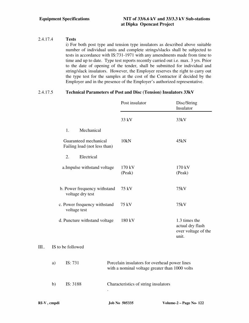
Equipment Specifications NIT of 33/6.6 kV and 33/3.3 kV Sub-stations
at Dipka Opencast Project
RI-V , cmpdi Job No 505335 Volume-2 – Page No- 122
2.4.17.4 Tests
i) For both post type and tension type insulators as described above suitable
number of individual units and complete strings/slacks shall be subjected to
tests in accordance with IS:731-1971 with any amendments made from time to
time and up to date. Type test reports recently carried out i.e. max. 3 yrs. Prior
to the date of opening of the tender, shall be submitted for individual and
string/slack insulators. However, the Employer reserves the right to carry out
the type test for the samples at the cost of the Contractor if decided by the
Employer and in the presence of the Employer’s authorized representative.
2.4.17.5 Technical Parameters of Post and Disc (Tension) Insulators 33kV
Post insulator Disc/String
Insulator
33 kV 33kV
1. Mechanical
Guaranteed mechanical 10kN 45kN
Failing load (not less than)
2. Electrical
a.Impulse withstand voltage 170 kV 170 kV
(Peak) (Peak)
b. Power frequency withstand 75 kV 75kV
voltage dry test
c. Power frequency withstand 75 kV 75kV
voltage test
d. Puncture withstand voltage 180 kV 1.3 times the
actual dry flash
over voltage of the
unit.
III.. IS to be followed
a) IS: 731 Porcelain insulators for overhead power lines
with a nominal voltage greater than 1000 volts
b) IS: 3188 Characteristics of string insulators
.
Equipment Specifications NIT of 33/6.6 kV and 33/3.3 kV Sub-stations
at Dipka Opencast Project
RI-V , cmpdi Job No 505335 Volume-2 – Page No- 123
c) IS: 8765 Specification for ceramic insulating materials
for electrical purposes.
d) IS: 8704 Methods for artificial pollution tests on high voltage
insulators for use on A.C. systems.
e) IS: 8269 Methods for switching impulse tests on high voltage
insulators.
f) Any other relevant IEC recommendations and standard approved practices
Equipment Specifications NIT of 33/6.6 kV and 33/3.3 kV Sub-stations
at Dipka Opencast Project
RI-V , cmpdi Job No 505335 Volume-2 – Page No- 124
2.4.18.0 SPECIFICATION OF FIRE FIGHTING EQUIPMENT:
2.4.18.1 SPECIFICATIONS OF PORTABLE CO2 FIRE EXTINGUISHERS
i) Application:
The portable CO2 type fire extinguisher will be used where fires due to wood,
paper, inflammable liquids, rubbish and fires due to electrical short circuits are
expected.
ii) Duty Conditions:
These fire extinguishers shall normally be stored at suitable locations in the
substations and shall be able to be used effectively whenever required in
shortest possible time. The places where these will be stored are usually dusty
at relative humidity in monsoon at 100% and temperature at 50 degrees
Celsius in summer.
iii) Scope of Supply:
The fire extinguisher shall conform to the specifications given in the
subsequent clauses and the scope of supply shall consist of the following:-
-Fire extinguisher consists of container along with cap, valve, rubber hoses,
brackets to support the extinguisher on the wall or on structural
members.
-Initial charge and required accessories.
-Operating manual giving details of recharging method also.
-Any other items required.
iv) Constructional details:
-The extinguisher shall be of 4.5 kg of capacity
-The extinguisher shall be compact in size, light in weight so that it can be
carried very easily from one place to other to combat fires.
-The extinguisher shall use CO2 as ingredient.
-The body of the extinguisher shall be made of stainless steel sheets or seam
less manganese steel sheets of adequate thickness to withstand the
pressure.
-The mouth of the container shall be fitted with stainless steel pipe, nozzle,
valve, PVC hose etc. The valve provided at the mouth shall be able to
control the discharge of fluid as required.
Equipment Specifications NIT of 33/6.6 kV and 33/3.3 kV Sub-stations
at Dipka Opencast Project
RI-V , cmpdi Job No 505335 Volume-2 – Page No- 125
-CO2 shall be charged in gas cartridges which are applied with suitable
material to avoid corrosion.
-The container shall be rechargeable type after its use.
-The life of the liquid shall be sufficiently long and properties shall not be
changed even though they are kept in temperatures of 50 degrees
centigrade continuously for long periods.
-The container shall be coated with two coats of signal red colour and enamel
paint.
-Every extinguisher shall have instruction plate fitted to it for easy use at times
of emergency.
-The extinguisher type shall be engraved on the container.
-The nozzle provided at the mouth shall be able to discharge CO2 at high
velocity so that it can cover larger areas and also penetrate deep into the fire
very fast.
2.4.18.2 DRY POWDER TYPE FIRE EXTINGUISHERS
i) Application:
The portable dry powder type fire extinguisher will be used where fires due to
wood, paper, inflammable liquids, rubbish and fires due to electrical short
circuits are expected.
ii) Duty Conditions:
These fire extinguishers shall normally be stored at suitable locations in the
substation and shall be able to be used effectively whenever required in
shortest possible time. The places where these will be stored are usually dusty
at relative humidity in monsoon at 100% and temperature at 50 degrees
centigrade in summer.
iii) Scope of Supply:
The fire extinguisher shall conform to the specifications given in the
subsequent clauses and the scope of supply shall consist of the following:-
- Fire extinguisher consists of container along with cap, valve, rubber hose,
brackets to support the extinguisher on the wall or on structural members.
- Initial charge and required accessories.
Equipment Specifications NIT of 33/6.6 kV and 33/3.3 kV Sub-stations
at Dipka Opencast Project
RI-V , cmpdi Job No 505335 Volume-2 – Page No- 126
- Operation manual giving details of recharging method also.
- Any other items required.
iv) Constructional details:
-The extinguisher shall be 5 kg capacity.
-The extinguisher shall be compact in size, light in weight so that it can be
carried very easily from one place to other to combat fires.
- The extinguisher shall use dry powder as ingredient.
- The body of the extinguisher shall be made of stainless steel sheets of
adequate thickness to withstand the pressure.
- The mouth of the container shall be fitted with stainless steel pipe or
MS plates, nozzle, valve and PVC hose. The valve provided at the
mouth shall be able to control the discharge of fluid as required.
- Dry powder shall be charged in gas cartridges which are applied with
suitable material to avoid corrosion.
- The container shall be rechargeable type after its use.
- The life of the material used shall be sufficiently long and properties
shall not be changed even though they are kept in temperatures of 50
degrees centigrade continuously for long periods.
- The container shall be coated with two coats of signal red colour and
enamel paint.
- Every extinguisher shall have instruction plate fitted to it for easy use
at times of emergency.
- The extinguisher type shall be engraved on the container.
- The nozzle provided at the mouth shall be able to discharge dry
powder at high velocity so that it can cover larger areas and also
penetrate deep into the fire very fast.
2.4.18.3 HYDRANT SYSTEM OF FIRE FIGHTING
2.4.18.3.1 SPECIFICATIONS OF STAND POST TYPE FIRE HYDRANT AND HYDRANT VALVES
i) Application:
Stand post type fire hydrants at DG shed, pump house and substation building
along with adaptors, hydrant valves will be installed as required for supplying
Equipment Specifications NIT of 33/6.6 kV and 33/3.3 kV Sub-stations
at Dipka Opencast Project
RI-V , cmpdi Job No 505335 Volume-2 – Page No- 127
water at required pressure and quantity to suppress the fire. This will be
connected to the main pipeline through reducer pipe and adopters. The valves
shall be able to work in dusty atmosphere.
All the Power Transformers (16 MVA and 5 MVA rating) shall be fitted High
Velocity Water Spray System for fire fighting purpose.
ii) Scope of Supply:
The scope of supply shall consist of the following items in required quantities
as per the specifications mentioned in the subsequent clauses
- Stand post type fire hydrant.
- Underground hydrant valve.
- Hydrant key and required accessories.
- Any other items for efficient use.
iii) Constructional Details:-
-The stand post type fire hydrant shall be manufactured as per IS:
908(Current).
-The hydrant post shall be of suitable internal diameter at the inlet it shall have
a male outlet which can be screwed into the female end of underground
hydrant valve. The outlet shall have female end so that fire hydrant hose can
be fitted to it.
-The hydrant post may be made of cast iron or MS steel. The minimum height
of post shall be 900 mm.
-The hydrant post shall be able to deliver required quantity of water at
required pressure
-The hydrant valve shall be of gun metal and manufactured as per relevant
Indian Standards.
-The hydrant valve shall have flanged inlet suitable for inlet pipe as per design
and the outlet shall be female type of suitable diameter with standard threads
on it.
-The hydrant valve shall be suitable to be installed underground and shall have
provision to be operated by a hydrant key made up of MS bar of suitable size
and length.
-The hydrant valve shall be of single outlet type.
Equipment Specifications NIT of 33/6.6 kV and 33/3.3 kV Sub-stations
at Dipka Opencast Project
RI-V , cmpdi Job No 505335 Volume-2 – Page No- 128
-The flange of the valve need not be provided with holes. Holes will be made
at site to suit the flange of the 'T' joint of the main pipe.
-Suitable stuffing boxes shall be provided in the hydrant valve.
-All the fittings shall be of good quality and workmanship, finish and free
from turns and sharp edges.
-The forgings and castings shall be sound and free from blow hole, scales and
other imperfections. On inspection if any of the defects are noticed in any one
piece, the entire lot may be rejected.
-The design shall be such that it will operate at maximum efficiency with
minimum maintenance.
-The valve and hydrant post shall be tested to a suitable hydraulic pressure and
there shall not be any leakage.
-All M.S. and C.I. parts exposed to water shall be painted with anti-corrosion
paint and outside shall be painted with post office red enamel paint.
2.4.18.3.2 SPECIFICATIONS OF FIRE HOSE BOXES/CABINETS
i) Application:
The fire hose boxes/cabinets will be used to store the fire hoses together with
nozzles and will be installed near the hydrant points on posts. The cabinets
are mainly meant for increasing the life of the hoses by preventing them from
exposing to heat, rains and other atmospheric conditions. These cabinets shall
also help in preventing thefts of hoses and shall be always ready for use in
emergency conditions.
ii) Scope of Supply:
-Fibre glass fire hose cabinet suitable to store two rolls of 15 m long and hose
pipe together with requisite nozzles and hose pipe couplers if required.
-Brackets and posts to erect the cabinet near the hydrant point.
-The supply shall be as per the specifications mentioned in the subsequent
clauses.
iii) Description of the cabinet:
-The cabinet shall be moulded out of red pigment of fibre reinforced
plastic.
Equipment Specifications NIT of 33/6.6 kV and 33/3.3 kV Sub-stations
at Dipka Opencast Project
RI-V , cmpdi Job No 505335 Volume-2 – Page No- 129
-The cabinet shall be fitted with fibre glass doors.
-The size of the cabinet shall be suitable to accommodate two rolls of 15 m.
length fire hoses in rolled condition along with couplers and nozzle.
-The cabinet shall be capable to resist the weight of the above-mentioned
hoses.
-The back wall of the cabinet shall be provided with metal inserts to provide
extra strength for mounting it on the suitable posts/on wall.
-The surface of the cabinet shall be finished to have a glassy surface.
-The cabinet shall be fitted with double doors. The doors shall be fitted with
brass hinges, ball type, self-locking arrangement, extra lock facility and
handles. The centre of the door panels shall be fitted with transparent acrylic
sheets.
-The cabinets shall be of light weight and shall be dust and water proof. Rain
guards and dust seals shall be provided at the doors.
-The material of the cabinet shall be non-corrosive, non-conductive, non-
bendable, un breakable and shall be more durable.
-The colour of the cabinet shall be red. `Fire hose cabinet' shall be written with
paint on the glass panel.
-Suitable brackets shall be provided to fix the cabinet on the post.
iv) Standards:
The cabinets shall be as per latest relevant Indian Standards or equivalent
International Standards.
2.4.18.3.3 SPECIFICATIONS OF FIRE HOSES:
i) Application:
The fire hoses will be used for supplying large quantities of water at high
pressure in an uninterrupted way from a suitable drain point up to the place
where fire occurs. The hoses will be stored in roll form in fibre glass hose
cabinets. These cabinets will be kept in open atmosphere wherein
temperatures as high as 50 degrees Celsius are expected to reach in summer
and relative humidity of 100% is expected in rainy season.
Scope of Supply:
The supply shall be as per the specifications mentioned in subsequent clauses
and shall consist of the following:
Equipment Specifications NIT of 33/6.6 kV and 33/3.3 kV Sub-stations
at Dipka Opencast Project
RI-V , cmpdi Job No 505335 Volume-2 – Page No- 130
Fire hoses of suitable diameter and 15 m long.
Constructional details:
i) The hose shall be made up of false canvas.
ii) The canvas shall be treated with suitable substance to improve its
mildew resistance characteristics so that flexing characteristics does
not deteriorate even though it is wet.
iii) The hose shall be light in weight.
iv) The hose shall have least resistance to flow of water so that frictional
losses are less.
v) It shall have long life and suitable for fighting industrial fires. It shall
not get damaged even after coming in contact with hot objects or due
to the heat radiated from fires that are being extinguished.
vi) The hose shall be resistant to rotting.
vii) Provision for fitting the gun metal female couplers shall be made to
connect another hose very easily, if required.
viii) Maximum length of the roll shall be 15 m.
ix) The hose shall withstand bursting pressures of at least 32 kg/cm2 or as
per relevant IS.
x) The hose shall not loose its characteristics even though they are kept in
atmosphere where temperature as high as 50 degrees Celsius are
reached and also relative humidity of 100% are reached.
Standards:
The hose shall be manufactured as per IS: 8423 current or any other equivalent
International Standards.
2.4.18.3.4 SPECIFICATIONS OF BRANCH PIPES, NOZZLES, NOZZLE SPANNERS AND HOSE
COUPLINGS
i) Application:
The hose couplings consists of male and female half couplings to which
branch pipe will be attached along with the nozzle for discharging water from
the fire hose on to the fire. These items will be stored in the fire hose cabinets
situated near the vertical hydrant posts.
Equipment Specifications NIT of 33/6.6 kV and 33/3.3 kV Sub-stations
at Dipka Opencast Project
RI-V , cmpdi Job No 505335 Volume-2 – Page No- 131
ii) Scope of Supply:
The scope of supply in each set shall include the following items conforming
to the specifications given in the subsequent clauses. The complete set shall
be kept inside the fire hose cabinets for ready use in case of emergency.
(a) One set of male and female couplings.
(b) One nozzle.
(c) One set of branch pipe
(d) Tools required for the assembly and dismantling of the above
items.
iii) Constructional details:
- All fittings shall be of good workmanship, finish and free from burns
And sharp edges.
- The forgings and castings shall be sound and free from blow-holes, scales,
cracks and other imperfections.
- The water way of the fittings shall have smooth finish.
- All the fittings shall conform to IS: 903 Current.
- All the accessories shall be able to withstand a hydraulic pressure of 2.1 MN/
sq mm (21 kgf / sq cm) for a period of 2 minutes. The hose shall not show any
sign of leakage or sweating.
- All the castings and forgings shall be made of copper alloy (gun metal). The
specifications of the material shall conform to the relevant Indian Standards as
specified in IS: 903 Current.
IV) DELIVERY HOSE COUPLING
- It shall consist of male half coupling, female half coupling and suitable
washers, nuts, bolts, etc.
- Provision shall be made so that both couplings can be tied together.
- The coupling shall be suitable for fire hose with 63 mm internal diameter and
other dimensions shall conform to IS: 903.
- Provision shall be kept to fix another half of a different branch pipe to the
female half coupling.
- Phosphor bronze wire conforming to IS: 7608 shall be used in the
coupling.
Equipment Specifications NIT of 33/6.6 kV and 33/3.3 kV Sub-stations
at Dipka Opencast Project
RI-V , cmpdi Job No 505335 Volume-2 – Page No- 132
- The washer used in the coupling shall conform to Type 'A' of IS:1937
(Current).
- The coupling surface shall be such that the hose can be fitted easily and will
not come out during operation.
v) NOZZLE:
- The nozzle shall be able to deliver the required quantity of water
smoothly.
- The constructional details and dimensions shall be as per IS: 903
Current.
- One end of the nozzle shall be provided with threads conforming to IS:2643
(Part-I) so that it can be fitted to the branch pipe.
- The inside diameter at discharge end of the nozzle shall be 30mm.
vi) NOZZLE SPANNER:
- The nozzle spanner shall be made out of steel of Grade C-35 or C-40 as per IS:
1570(Part 5).
- The shape and size of the spanner shall be as per IS: 903.
- The nozzle spanner shall be given anti-corrosive treatment by a suitable coat
of chromium or zinc.
- The spanner shall be tested as specified in IS: 903 for testing the permanent
deflection of the spanner job.
v) BRANCH PIPE:
- It shall be of required diameter and length
- The wall thickness shall be sufficient to withstand the water pressure.
- The branch pipe shall have provision at one end for connecting the female half
coupler of the hose and the other end with threads for fitting the nozzle.
- The branch pipe shall conform to IS 903 (current).
vi) Standards:
All the accessories such as fire hose couplings, branch pipes, nozzles, nozzle
spanners shall be manufactured as per IS: 903(Current).
Equipment Specifications NIT of 33/6.6 kV and 33/3.3 kV Sub-stations
at Dipka Opencast Project
RI-V , cmpdi Job No 505335 Volume-2 – Page No- 133
2.4.18.4 SPECIFICATIONS OF SAND BUCKETS
i) Application:
These buckets will be used to store sand and will be kept in Control room,
substations, Substation outdoor yard etc.
ii) Constructional details:
a) The sand bucket shall be of 9 litre capacity.
b) These shall be made/manufactured from M.S. sheet steel of 24 gauge
conforming to relevant I.S.
c) The bucket shall be of round bottom.
d) The bucket shall have a handle so that it can be hung from hooks
placed in the brackets or fire bucket stand.
e) Riveting/welding shall be used for joining the ends of vertical wall.
f) The whole bucket shall be galvanised after manufacture.
g) The bucket shall be painted with two coats of corrosion resistant red
paint. The bottom shall be painted with black colour. On the outer
surface of the bucket letters 'fire' shall be written in black colour. The
inside of the bucket shall be painted with an anticorrosive paint of dark
shade.
2.4.18.5 SPECIFICATIONS OF LANDING VALVES FOR INTERNAL FIRE HYDRANTS:
i) Application:
Landing valves for internal fire hydrants will be installed at different locations
in side the substation building for supplying water to suppress the internal
fires. These valves will be connected to the main water supply line through
reducer, flanges etc.
ii) Scope of supply:
The scope of supply shall consist of the following items in required quantities
as per the specifications mentioned in the subsequent clauses:
a) Double head type valve along with independent controlling
valves
b) Brackets to support the valves
c) Installation drawing
d) Any other items for efficient use of the landing valve
Equipment Specifications NIT of 33/6.6 kV and 33/3.3 kV Sub-stations
at Dipka Opencast Project
RI-V , cmpdi Job No 505335 Volume-2 – Page No- 134
iii) Constructional features:
a) The landing valve shall conform to IS: 5290 (current) and shall have the
approval of Tariff Advisory Committee for use in high rise industrial
structures.
b) The landing valve shall be of double ended type with outlets at right angles
to the axis of main pipe.
c) Independent control valves shall be provided for the outlets.
d) Suitable arrangement shall be made for supporting the valve on wall.
e) The hydrant valve shall be made of Gun Metal. The wheel shall be of cast
iron.
f) Suitable stuffing boxes shall be provided in the valves to avoid any leakage.
g) All the fittings shall be of good quality and workmanship, finish and free
from turns and sharp edges.
h) Forgings and castings shall be wound and free from blow holes, cracks,
scales and other imperfections on inspection, if any defect is noticed in any
one piece, the entire lot may be rejected.
i) Design shall be such that it will operate at maximum efficiency with
minimum maintenance.
j) All M.S. and C.I. parts exposed to water shall be painted with anti-corrosion
paint and out side shall be painted with post office red enamel paint. Alloy
parts shall also be painted with suitable paint.
2.4.18.6 SPECIFICATIONS OF ELECTRICALLY OPERATED CENTRIFUGAL PUMP-MOTOR
SET
i) Application:
The pump motor set shall be used on surface for pumping water for fire
fighting purposes. The pump shall draw water from an underground sump
(1,35,000 litre capacity, minimum) and supply to the nozzles for spraying the
water at fire.
ii) Duty:
The pump motor set shall be able to operate continuously at full load in
ambient temperature upto 50 degrees Celsius, relative humidity up to 100%.
The motor and pump shall be suitable for frequent starts and stops.
Equipment Specifications NIT of 33/6.6 kV and 33/3.3 kV Sub-stations
at Dipka Opencast Project
RI-V , cmpdi Job No 505335 Volume-2 – Page No- 135
iii) Scope:
The scope of supply shall consist of the following:
(a) Pump along with coupling, motor and starter (push button type)
(b) Standard Accessories: These shall include bed frame, priming funnel,
pressure gauge, strainer, non return valve etc.
(c) First fill of grease etc.
(d) Foundation bolts.
(e) Special tools for maintenance of the pump
(f) Any other items which are necessary for efficient operation of the
pump but not covered in this list.
The other specifications of the Pump motor set shall be as given in subsequent
clauses.
iv) Description of the Equipment:
Mechanical:
a) The pump shall be of centrifugal type.
b) The impeller shall be made from close grained C.I. of Grade 20
conforming to IS: 210(Current). This shall be free from blow holes.
Impeller shall be properly balanced to avoid undue vibration.
Provision of holes in the impeller for balancing is not acceptable.
c) The pump casing shall be of horizontal split type depending on design
considerations. This shall be made from close grained cast iron of
Grade 20 conforming to IS: 210(Current) for the main pump. The
casing shall be free from blow holes. The casing shall be of volute
construction for smooth and efficient flow of liquid.
d) The pump shall have priming funnel for priming purpose. The pump
shall not get damaged when it is started in partially primed condition.
e) Proper flanges shall be provided on the pump body for connecting the
suction and delivery pipes.
f) Proper sealing arrangement consisting of stuffing boxes fitted with
suitable packing material shall be provided to prevent leakage within
the casing. The sealing arrangement shall be such that replacement of
packing material does not require dismantling of any other parts except
the glands.
Equipment Specifications NIT of 33/6.6 kV and 33/3.3 kV Sub-stations
at Dipka Opencast Project
RI-V , cmpdi Job No 505335 Volume-2 – Page No- 136
g) Suitable deep groove ball bearings or any other type antifriction
bearings with proper lubrication shall be provided. The bearings shall
have a life of min.50000 hours at full load.
h) The bearing housing shall be provided with effective sealing
arrangement against the entrance of water or dust. Grease cups shall
be provided for lubrication purpose. A drain plug shall be provided
below each housing of the pump. The housings shall be provided with
grease nipples also.
i) 'V' belt drive is not acceptable. Motor shall be connected to the Pump
through a pin bush type flexible coupling.
j) The flexible coupling with output transmitting capacity 1.25 times the
motor rating shall be provided. The coupling shall be provided with a
coupling guard. The coupling shall be able to absorb combination of
parallel, angular and axial misalignments.
k) The base frame shall be fabricated from M.S. structural steel to meet
the duty condition. The pump and motor shall be properly aligned in
the works of manufacturer before supply. Lifting lugs shall be
provided for easy lifting.
l) The pump shall be suitable for frequent starts and stops.
m) The pump offered shall be suitable for operating at a head variation of
+20% to -20% of the duty point head.
n) Suitable arrangement shall be provided for balancing the hydraulic
thrust.
o) Direction of rotation of pump shall be indicated clearly on the pump
body.
Electric Motor:
a) The motor shall be horizontal, foot mounted, squirrel cage induction
type, TEFC, Non-flameproof. The enclosure protection of motor shall
be IP-54 and S1 - continuous duty with Class 'B' insulation suitable for
DOL starting. It shall be suitably rated to meet the duty conditions and
also requirement at any point of the pump operating range.
The synchronous speed of the motor shall be 1500 r.p.m. The motor
shall be suitable for 415 V, 3 phases, 50 Hz A.C. supply. The cable
end boxes shall be suitable for copper conductor PVCSWA cables of
suitable size. The operating characteristics at rated output, frame size,
insulation class shall be given in the offer.
Equipment Specifications NIT of 33/6.6 kV and 33/3.3 kV Sub-stations
at Dipka Opencast Project
RI-V , cmpdi Job No 505335 Volume-2 – Page No- 137
b) Motor shall be capable to deliver rated output with -
-the terminal voltage differing from its rated value by not more than+/-
10% or
-the frequency differing from its rated value by not more than +/-
6% or any combination of above limiting to 10 %
c) Motor shall be operated from a remote place.
d) Motor Earthing: Provision for earthing of Motor in accordance with
relevant provision of IS: 3043-1966 or latest revision thereof and
relevant IE rules shall be given. There shall be min.2 points.
e) Limits of Vibration shall be as per IS: 4729-1968. Double amplitude of
vibration for the motors shall be within the limit specified in IS: 4729.
f) The motor shall conform to the following IS or their latest
revisions thereof:
- IS: 325-1978 - Specifications of 3 phase
induction motor
- IS: 4691 - Degrees of Protection provided by
Enclosures for rotating Electrical
machinery
- IS: 6362 - Cooling
- IS: 4722 - Duty type
- IS: 4728 - Terminal Marking
- IS: 8789 - Value of performance characteristics
- IS: 7538 - Motor with centrifugal pump
- IS: 1231 - Dimensions of three phase foot
Mounted induction motor
- IS: 2253 - Type of construction and mounting of
motors
Starter:
A push button type start / stop switch will be provided in the pump house for
starting and stopping in case emergency. The pump will receive power from a
MCC and controlled from a central control room.

Equipment Specifications NIT of 33/6.6 kV and 33/3.3 kV Sub-stations
at Dipka Opencast Project
RI-V , cmpdi Job No 505335 Volume-2 – Page No- 138
A diesel operated pump shall also be supplied and installed in the pump room
for fire fighting purpose.
Equipment Specifications NIT of 33/6.6 kV and 33/3.3 kV Sub-stations
at Dipka Opencast Project
RI-V , cmpdi Job No 505335 Volume-2 – Page No- 139
2.4.19.0 SPECIFICATION FOR LED LAMP & ILLUMINATION SCHEME
The illumination scheme shall be designed such that the outdoor and indoor areas remain illuminated properly to achieve safety and operational efficiency and convenience. The levels of outdoor and indoor illumination shall be as specified in relevant IS.
In outdoor switchyard, totally enclosed dust and vermin proof luminaries (IP 65) with LED lamps shall be used. The junction boxes shall be as per IS: 2148 with IP 65 enclosures.
Seven nos. of 16 meter high lighting towers shall be erected in the substation yard for mounting the lamp fixtures. Each tower will accommodate four numbers of 200W LED flood lights for lighting the entire yard. Additionally four numbers of bracket mounted outdoor street lighting fixtures with 90 W LED lamp will be erected on roof top of the substation building for illuminating the area around the substation building For substation indoor illumination, the control room area shall have indoor type twin industrial type LED fixtures shall be used in other service rooms. The corridor will be illuminated by 20 W LED fixtures. All wiring for indoor illumination shall be of concealed type with PVC conduit.
Sizes of cables will be selected based on continuous current ratings with derating factors and a maximum of 3% voltage drop.
The details of calculations along with mounting scheme, lumen output considered, type of luminiares etc. should be furnished by the tenderer for approval from the customer.
2.4.19.1 SPECIFICATION OF LIGHTING FIXURES
This specification covers requirement for fixtures of LED lamps in various applications.
i) LED lamps of Best in class make shall be used for the purpose. (ii) The luminary casing/housing shall be of Stainless steel SS304 grade or
aluminium having high conductivity preferably grade 5000 or similar to high conductivity heat sink material.
(iii) The electronic components used shall be as follows:-
a) IC (Integrated circuit) shall be of industrial grade or above. b) Metallic film / Paper/Polyester Capacitor shall be rated for a sustained
operating temperature of 105ºC c) The resistors shall be preferably made of metal film of adequate rating.
The actual rating versus loading shall be by a factor of 3.
Equipment Specifications NIT of 33/6.6 kV and 33/3.3 kV Sub-stations
at Dipka Opencast Project
RI-V , cmpdi Job No 505335 Volume-2 – Page No- 140
d) The junction temperature of the Switching devices such as transistors and MOSFETs etc. shall be within prescribed limit.
e) The protective cum adhesive coating used on PCBs should be cleared and transparent and should not affect colour code of electronic components or the product code of the company.
f) The construction of PCBs and the assembly for components for PCBs should be as per IS standards.
g) The electronics covered for this equipment shall pass all the tests called for in the above specification.
h) The infrastructure for Quality Assurance facilities as called for in the above specification must be available at the manufacturing works. In-house testing facility for Quality Assurance should be present.
iv) The connecting wires used inside the luminaries, shall be low smoke halogen
free, fire retardant e-beam cable and fuse protection shall be provided in input side.
v) Care shall be taken in the design that there is no water stagnation anywhere.
The entire housing shall be dust and water proof having IP65 protection as per IS 2148.
vi) The LED Module(s), Driver gear, etc. shall be designed in such a way so that
temperature of heat sink shall not exceed 1500C above the ambient temperature.
vii) All the material used in the luminaire shall be halogen free and fire retardant
confirming to UL94.
viii) In-Built protection of the luminary are as follows a) Surge Protection – 4 kV b) Over Voltage Protection – 280 V c) Short Circuit Protection – Constant current limit mode. d) Over temperature protection – Auto shut off.
(ix) Optics of the luminary are as follows – Secondary lens array should be provided for optimized roadway photometric
distribution.
(x) Photometric measurements in accordance with LM-79/IS16105. Lens material should be optical high grade PMMA with more than 90% light transmittance.
Any material, component or accessory not specifically stated in this specification but necessary for trouble free operation shall deemed to be included.
2.4.19.2 OTHER RELEVANT STANDARDS
The other standards applicable are as under:
Equipment Specifications NIT of 33/6.6 kV and 33/3.3 kV Sub-stations
at Dipka Opencast Project
RI-V , cmpdi Job No 505335 Volume-2 – Page No- 141
1. IS:16101: 2012 General Lighting - LEDs and LED modules – Terms and Definitions
2. IS:16102(Part 1): 2012 Self- Ballasted LED Lamps for General Lighting Services Part 1 Safety Requirements
3. IS:16102(Part 2): 2012 Self-Ballasted LED Lamps for General Lighting
Services Part 2 Performance Requirements
4. IS:16103(Part 1): 2012 Led Modules for General Lighting Part 1Safety Requirements
5. IS:16103(Part 2): 2012 Led Modules for General Lighting Part 2 Performance
Requirements 6. IS:15885(Part2/Sec13): 2012 Safety of Lamp Control Gear Part 2 Particular
Requirements Section 13 d.c. or a.c. Supplied Electronic Controlgear for Led Modules
7. IS: 16104: 2012 d.c. or a.c. Supplied Electronic Control Gearfor LED Modules
- Performance Requirements 8. IS: 16105: 2012 Method of Measurement of Lumen Maintenance of Solid
State Light (LED) Sources 9. IS: 16106: 2012 Method of Electrical and Photometric Measurements of Solid-
State Lighting (LED) Products 10. IS: 16107 Part 1:2012 Luminaires Performance Part 1 General
Requirements 11. IS: 16107-1:2012 Luminaires Performance Part 2 Particular Requirements
Section 1 LED Luminaire 12. IS: 16108: 2012 Photo biological Safety of Lamps and Lamp System
2.4.19.3 CONSTRUCTION
All lighting fixtures shall be Pressure Die Cast Aluminum housing with corrosion resistant polyester powder coating & safety as per IS 10322 and shall have mounting bracket with aiming & locking facilities. Power Factor of the fixtures shall be not less than 0.95.
2.4.19.4 Flood light fixtures
The reflector shall be made of Pressure Die Cast Aluminum housing with corrosion resistant polyester powder coating & safety as per IS 10322.
The fixture shall have mounting bracket with aiming & locking facilities.
Equipment Specifications NIT of 33/6.6 kV and 33/3.3 kV Sub-stations
at Dipka Opencast Project
RI-V , cmpdi Job No 505335 Volume-2 – Page No- 142
The fixture shall have good thermal management system provided with suitable large surface area with fins to dissipate the heat to ambient air and block any accumulation of dust / water.
The fixture shall be suitable for 200 Watt LED lamp.
The cable entry gland shall be fitted to the lamp holder housing
A graduated disc shall be provided to enable adjustment in the spinning angle of the fixture after mounting the fixture on a bracket.
The fixture shall be mounted on a bracket.
2.4.19.5 Street light fixtures
The reflector shall be made of Pressure Die Cast Aluminum housing with corrosion resistant polyester powder coating & safety as per IS 10322.
The cable entry shall be from the side.
A locking device shall be provided to prevent unauthorised opening of the fixture.
The fixture shall be suitable for mounting 30 Watt /50 Watt/120 Watt/ 200 Watt LED lamps.
2.4.19.6 Mast top flood light fixtures for LED lamps
The reflector shall be made of Pressure Die Cast Aluminum housing with corrosion resistant polyester powder coating & safety as per IS 10322.
The aluminium frame-work shall carry the LED lamp & control gear components like ballasts and starters.
The p.f. correction capacitor & the HRC fuses shall be housed in a separate box below the framework for easy replacement.
The aluminium frame-work shall be fixed to a G.I. pipe
The G.I. pipe shall be suitable for mounting on a mast 12 m long.
The fixture shall be suitable for 200 Watt LED lamps.
.
2.4.19.7 Emergency lighting
The emergency lighting will be through 18 W LED lamp
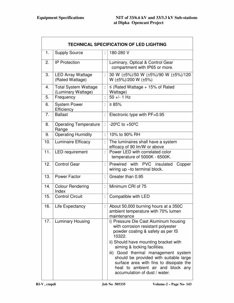
Equipment Specifications NIT of 33/6.6 kV and 33/3.3 kV Sub-stations
at Dipka Opencast Project
RI-V , cmpdi Job No 505335 Volume-2 – Page No- 143
TECHNICAL SPECIFICATION OF LED LIGHTING
1. Supply Source : 180-280 V
2. IP Protection Luminary, Optical & Control Gear compartment with IP65 or more.
3. LED Array Wattage (Rated Wattage)
: 30 W (±5%)/50 W (±5%)/90 W (±5%)/120 W (±5%)/200 W (±5%)
4. Total System Wattage (Luminary Wattage)
: ≤ (Rated Wattage + 15% of Rated Wattage)
5. Frequency : 50 +/- 1 Hz
6. System Power Efficiency
: ≥ 85%
7. Ballast : Electronic type with PF>0.95
8. Operating Temperature Range
: -20ºC to +50ºC
9. Operating Humidity : 10% to 90% RH
10. Luminaire Efficacy : The luminaires shall have a system efficacy of 90 lm/W or above
11. LED requirement : Power LED with correlated color temperature of 5000K - 6500K.
12. Control Gear : Prewired with PVC insulated Copper wiring up –to terminal block.
13. Power Factor : Greater than 0.95
14. Colour Rendering Index
: Minimum CRI of 75
15. Control Circuit : Compatible with LED
16. Life Expectancy : About 50,000 burning hours at a 350C ambient temperature with 70% lumen maintenance
17. Luminary Housing i) Pressure Die Cast Aluminum housing with corrosion resistant polyester powder coating & safety as per IS 10322.
ii) Should have mounting bracket with aiming & locking facilities.
iii) Good thermal management system should be provided with suitable large surface area with fins to dissipate the heat to ambient air and block any accumulation of dust / water.
Civil & Structural Works NIT of 33 /6. 6 kV and 33/3. 3 kV substations
at Dipka OCP
RI-V, cmpdi Job No 505335 Volume-2- Page No- 144
2.5 CIVIL AND STRUCTURAL WORKS
2.5.1 GENERAL
The scope of work under this contract shall include design, construction and successful
commissioning of all balance civil and structural works, supply of detailed design, working
drawings including all relevant calculations and all necessary works as may be needed for
testing and commissioning, elimination of all teething trouble, performance test and handing
over of the plant as envisaged in detailed scope of work and system description. The
necessary construction, erection, commissioning equipment related to civil engineering works
shall be provided and required materials should be transported, fabricated, erected at the site
of work by the contractor. Due consideration shall be given for economy, architecture and
functional utilities. This is a contract for purchase of complete installation including planning
and design, manufacture, execution, supply, erection of civil & structural work. Accordingly,
all works needed for successful completion and operation of the plant shall be covered in the
Scope of work whether specifically mentioned here or not.
Adherence to Indian Standards
All the works including designs, drawings, construction, fabrication, testing, erection,
etc. shall be done strictly as per relevant BIS Code of Practices. Wherever no Indian
Standard is available other international standards may be used only as per its
applicability and justification.
2.5.2 Basic scope
The scope of work covers all the related balance civil and structural works, detailed
designing of the same and successfully commissioning of the civil and structural
works for handing over the substation. This shall inter alia, include the following:
2.5.2.1 Design & engineering of all civil and structural works of the plant.
2.5.2.2 Execution of all balance civil/structural works consisting of the following:
a) Preparation of construction site.
b) Supply of fabricated structural steelwork and shaped rebars as required.
c) Supply of all civil construction materials and other materials required.
d) Execution of all civil works.
e) Fabrication/erection of structural.
f) All civil and structural works required for equipment and accessories under
supply.
g) Excavation/ construction/ erection/ installation and commissioning of all auxiliary
services such as sanitary, drainage, roads, pathways, substation building, lighting
towers, landscaping/ grading/ levelling/fencing/site clearing as detailed elsewhere.
h) Transportation of all construction materials to site.
i) Water supply arrangement for potable, industrial and fire fighting purposes.
j) Drainage and sewage disposal (for domestic and industrial sewage) including its
dovetailing with the existing system. (if existing near by)
k) Fire fighting arrangement
Civil & Structural Works NIT of 33 /6. 6 kV and 33/3. 3 kV substations
at Dipka OCP
RI-V, cmpdi Job No 505335 Volume-2- Page No- 145
l) Roads, pavements, retaining walls (if required), culverts, etc.
m) All the protective measures for proper drainage for safety of structures, against
ingress of water / seepage due to seasonal nallahs and its tributaries which may be
flowing through the construction site area as per actual site conditions and
requirement.
n) All the protective measures for safety of men and materials during construction
against rail/dumper movements on existing railway tracks/haul roads.
2.5.2.3 Following will be supplied to the bidders by SECL, the customer/Principal employer.
a) Detailed survey plan of site including contour map at an interval of 1 m.
b) The geo-technical report, hydrological, blasting and rainfall data including any
other data related to design and execution.
2.5.2.4 Perception and remedial measures for the safety of entire substation area under the
scope keeping in view the adjoining natural and artificial features such as hill slopes,
nallah, buildings, etc.
2.5.2.5 Any other works/services not mentioned but required for the completion and
commissioning of the substation.
2.5.3 DESIGN /ENGINEERING
2.5.3.1 Design Criteria
All detailed design and working drawings will be developed with proper co-
ordination and inter-relation with mechanical and electrical equipment. The design of
RCC structure shall be carried out in general as per code of practice of plain and
reinforced concrete for general buildings construction BIS 456-2000 and other
relevant standards including up-to-date amendments. The steel structure shall be
designed and fabricated as per Code of practice for use of structural steel in general
building construction BIS 800 (latest edition) with up to date amendments and other
relevant IS standards. The building/ structure shall conform to local by-laws, rules
and regulations for industrial buildings and as per relevant Indian Standards. Latest
codes of practice with amendments up to date shall be strictly followed. In the
absence of BIS codes, approved international bodies’ codes can be considered for
design as per its applicability and justification.
The bidder shall be responsible for and shall pay for any alterations of the work due to
any discrepancies, errors or omissions in the design and drawings or other particulars
supplied by him, whether such design, drawings or other particulars have been
approved by customer or not.
2.5.3.2 Load consideration
Loads to be considered in design shall be as per relevant BIS codes of practices.
Generally, in design the effect of dead loads, live loads, load due to impact, vibration,
erection, wind load, seismic loads, dust load and effect of blasting etc., wherever
applicable, shall be considered. The loads due to equipment shall be considered by the
bidders themselves. In general, live load, wind loads, etc shall be as per BIS-875
(latest edition). Seismic loads to be considered in design shall be as per BIS 1893
(latest edition). Effect due to blasting (maximum charge pr delay of 20000 Kg at a
Civil & Structural Works NIT of 33 /6. 6 kV and 33/3. 3 kV substations
at Dipka OCP
RI-V, cmpdi Job No 505335 Volume-2- Page No- 146
distance of approximately 1000m) is to be considered while designing the structures,
as per the provision of BIS: 6922 with latest revision:
2.5.3.3 The topography factor for the calculation of design wind pressure shall be calculated
as per BIS 875 read with the latest amendment and shall not be less than 1.05.
2.5.3.4 Analysis & Design
All RCC and steel structure shall be designed in accordance with relevant IS Codes of
practice of latest revision. In the analysis of structures, the worst loading combination
of equipment loads, their impact, wind/seismic loads/blasting effect and other loads as
envisaged shall be considered.
2.5.3.5 Design drawing & detailed engineering
Broadly all the dimensions as given in NIT drawings are to be followed for bidding
purpose. However, these dimensions are indicative & may require changes during
detailed design.
Preparation
All the drawings shall be prepared in accordance with the provision of latest Indian
Standards. All drawings shall be sufficiently detailed and dimensioned to help in
speedy construction, fabrication and erection of structures. Wherever, any structure is
presented in more than one sheet of drawings, same scale and notations shall be used
in all the sheets for linking the drawings with each other. All modifications made in
structure during various stages of construction should be duly incorporated in working
drawings.
Bar bending schedule, detailed material list and specification of works shall be
prepared / detailed for reference. Working drawing shall also include general
arrangement drawings showing plans at different levels with sectional elevations.
Separate detailed drawing shall be prepared for inserts and anchor bolts including
their fixing details. The design drawings associated with steel structure should show
the force in the members, complete details of all members, joints, gusset plates,
welding, riveting, bolting, etc. The drawings should also show the weight of each
assembly/sub-assembly as far as possible. In addition to design drawings, fabrication
drawings shall also to be prepared, showing item-wise details, erection units,
materials list, details of fasteners with assembly, etc. for reference.
2.5.3.6 Submission of Design/Drawings
The contractor shall submit all the relevant detailed design calculations, general
arrangement/detailed drawings, for approval of owner / consultant on standard size
sheets. All the designs/drawings/details should be submitted in CDs also.
The contractor should also submit bar bending schedule, fabrication drawings,
detailed material lists, specification of works etc. for reference.
Scrutiny and approval of drawings may be carried out through the consultant engaged
by the owner. The following designs/ drawings are to be approved by the owner/
consultant.
Civil & Structural Works NIT of 33 /6. 6 kV and 33/3. 3 kV substations
at Dipka OCP
RI-V, cmpdi Job No 505335 Volume-2- Page No- 147
i) General Arrangement Drawings
ii) Detail design calculations
iii) Detail civil and structural drawings
iv) Any other drawings relevant for execution/fabrication of civil/structural works
Contractor shall submit for approval six sets of drawings along with detailed design
calculations including analysis of force/stress in the structure along with the source
from where data, except BIS codes, have been taken. Photocopies of such data should
be submitted along with the design.
2.5.3.7 Procedure of Approval of drawings
The Owner shall have the final say in the approval of drawings. Drawings so
submitted will become the property of the Owner. The approval of the drawings does
not absolve the Contractor from the overall responsibility of the contractor for
completion of the plant and its successful operation. The Contractor shall be
responsible for and shall pay for any alterations of the work due to any discrepancy,
errors or omissions in the drawings or particulars supplied by him, whether Owner has
approved such drawings or other particulars.
Approval by Owner / Consultant
Design & drawing, submitted by the contractor, shall be scrutinised by owner/
consultant. Out of six sets of drawing submitted to the owner, one copy will be sent to
contractor after scrutiny with comments, desired modification or approval as the case
may be. The contractor shall carry out the necessary rectification in drawings after
discussion with owner in a reasonable time as agreed upon mutually and re-submit six
copies of such revised drawings for approval of owner. Revised drawings shall then
be scrutinised and approved if the comments made by the owner are incorporated /
taken care of. One copy of such drawing will be sent to the contractor after approval.
2.5.3.8 As Built Drawings
Contractor shall make necessary correction /modification in the drawing as per actual
after completion of work and shall prepare “as built drawing”. The Contractor shall
supply such 8 (eight) sets of prints of “as built drawing” to the Owner along with one
set of reproducible drawings on polyester paper in ink. The same will hold good for
other documents also to be supplied by the Contractor under the heading of basic
scope. All drawings should be prepared on AutoCAD in standard format and CD
containing such drawing shall also be supplied along with hard prints.
2.5.4 Pert Network
After the issue of letter of Intent, the bidder will prepare a master plan PERT
NETWORK incorporating all the major activities for the successful installation and
commissioning of plant on turn key basis and submit it to customer for his approval
and comments.
Civil & Structural Works NIT of 33 /6. 6 kV and 33/3. 3 kV substations
at Dipka OCP
RI-V, cmpdi Job No 505335 Volume-2- Page No- 148
The detailed PERT NETWORK will be prepared for all major activities enlisted in the
master PERT NETWORK. The detailed PERT NETWORK will be further discussed
with customer and form the basis of monitoring of the project as a whole or activity
wise. Necessary corrections will be carried out from time to time by the bidder in
consultation with the representative of customer but within the overall limit of time as
described in master NETWORK. All the activities of the contract will proceed on the
line of approved PERT NETWORK.
2.5.5 Technical specifications
2.5.5.1 All workmanship, materials and work items shall confirm to relevant IS / BIS /
MORTH / NBC STANDARDS. In case of items not adequately covered by above
mentioned Indian Standards, the CPWD / NBO practices shall be followed.
2.5.5.2 Safety Measures FOR CIVIL WORKS
In respect of safety, Part – 7 Constructional Practices & Safety of National Building
Code – 2005 shall be followed. All necessary safety measures to be adopted as
recommended by relevant IS / BIS code to protect adjunct / nearby structure,
workmen etc.
All works shall be carried out as per the item description and design & drawing
supplied and as per the relevant IS / BIS / NBC – 05 and as per direction of the
Engineer-in-Charge.
2.5.6 Scope of Work:
The scope of work is being provided in following paras. However, bidders must visit the site
of balance work to be executed and assess themselves regarding actual position/ condition/
status of the existing construction before quoting their rates.
Any omission, alteration and additional work not mentioned shall be deemed to have been
included in the scope of work for successful completion of the turnkey project without any
change in the price and billing schedule or extra time for execution.
The status listed below is indicative and may vary from description given. Bidders must
have an assessment of their own, with prior inspection, before quoting. The department
is not responsible for any deviation/omission not indicated here in under.
2.5.6.1 Substation Building: (Identical for Sub-stations 1,2 and 3)
One number substation building with minimum plinth area 15mx21m i.e. 315 sq.m.is to be
constructed in this contract. The location of substation has been mentioned elsewhere in the
document. The substation will have Control room, Capacitor bank room, Battery Room, Store
Room, office room, toilet facilities etc. The plinth level of the building shall be about 450
mm above final accepted ground level around the building. The details of the rooms provided
in the substation building will be as given below:
The substation building shall be of RCC framed structure with brick walls and RCC roof.
The roof height shall be minimum 4.5 m. The plastered internal surface shall be finished
with plastic emulsion paint of approved shade or any other approved finish depending on
functional need. Outer surface is to be plastered and finished with weather coat paint.
Required doors with steel frames, paneled aluminum windows, rolling shutters (for control
Civil & Structural Works NIT of 33 /6. 6 kV and 33/3. 3 kV substations
at Dipka OCP
RI-V, cmpdi Job No 505335 Volume-2- Page No- 149
room) will be provided. All windows will be protected by grills of suitable and approved
pattern. The doors shall be of flush door shutters with proper locking arrangement. The
noise level in the control room shall be kept below 60 db. False ceiling shall be provided in
the control room as well as in the office room.
The floor of stores and office room shall be of I.P.S flooring preceded by 150 mm thick PCC
of M-20 grade over the base course. The floor finish of Battery room will be acid proof. The
floor of the control room will have PVC sheet finish (minimum 2.5mm thick) for ensuring
30kV insulation level and this shall be heat, acid and mineral resistant.
The battery room and toilets will be provided with 600 mm sweep exhaust fans. Required
number of light fittings, fans, sockets, ceiling roses etc. will be provided.
The toilet will be provided with required sanitary fittings and associated plumbing work etc.
The facilities shall include water closet, urinals, wash basins, looking mirror, cistern, towel
rail, soap tray, toilet paper holder, glass shelf, flush door, taps, valves etc. The skirting in
toilet up to height of 1.5 m above finished floor level shall be glazed tile. The floorings shall
be of rectified glazed tile.
Skirting of standard height is to be provided in all utility buildings. Plinth protection of 1.5 m
wide shall be provided all around the substation building.
The schematic civil engineering drawing of sub-station building is enclosed in this document.
The details of equipment have been mentioned in the electrical sections of the document.
The layout of the cable trench will be as per system requirement. The top level of the cable
trench shall be kept minimum 0.5 m above finished ground levels and the plinth of the
building shall be fixed accordingly. Inside the substation building all cable trenches shall be
covered with aluminium cover with lifting facility.
Indicative status of existing construction of sub-station buildings:
a) Sub-station No. 1 : RCC frame work with roof slab, Brick work, Internal & External plastering, fixing of door
frame, ceiling plaster, flooring, door, window, grill fixing have been executed.
b) Sub-station No. 2 : RCC frame work of the building and brick work has been constructed upto roof level without
roof casting. No fixing or finishing work has been done.
c) Sub-station No. 3 : Physical progress is NIL.
2.5.6.2 Substation outdoor yard:
The ground area in the outdoor yard of the substation switch yard portion will have to be
leveled, suitably conditioned with anti-grass treatment before providing crushed stone. The
crushed stones will be of 25 mm x 25 mm size and will be spread uniformly to reduce shock
hazard. The thickness of crushed stone will be as per design consideration and approval of
DGMS/ Electrical Inspector.
Civil & Structural Works NIT of 33 /6. 6 kV and 33/3. 3 kV substations
at Dipka OCP
RI-V, cmpdi Job No 505335 Volume-2- Page No- 150
Out-door yard area will be as indicated in relevant drawing.
Indicative status of existing construction of outdoor yard :
Sub-station No. 1,2 & 3 :
Physical progress is NIL.
2.5.6.3 Outdoor Structures:
Supply of galvanized steel, fabrication and erection of gantries/ towers/ supporting stools for
CT’s, PT’s, lightning arrestor, vacuum circuit breakers, isolators and other associated
electrical equipment structures etc. as per system drawing will be in the scope of this work.
All outdoor structures shall (except incoming and outgoing feeders supporting steel structures
which will be on rail pole sections) be finished with Aluminum painting over base coat of
primer. The structures have to be designed for the equipment/ attachments proposed to be
mounted/ connected on it. Suitable foundation considering the expected load and soil bearing
capacity is to be provided. Protective anti climbing measures on the incoming structures and
danger boards are to be displayed on the relevant structures.
Indicative status of existing construction of outdoor structures :
a) Sub-station No. 1 :
A few no. of foundations have been executed. However, in the absence of any structural steel
work, these foundations are to be dismantled and reconstructed as per design requirement.
b) Sub-station No. 2 : Physical progress is NIL.
c) Sub-station No. 3 :
Physical progress is NIL.
2.5.6.4 Cable Trenches
All the power /lighting cables, control cables will be laid on separate cable hangers in the
cable trenches provided inside the sub-station building and outdoor yard. The cable trenches
will be of sufficient size. The floor of the cable trench will be provided with a gradient for
easy flow of water to a place outside the substation yard. The trenches provided in the out-
door yard will be covered by means of pre-cast RCC covers which can be lifted easily. Inside
the substation building the cable trenches will be covered with aluminum lids with easy
lifting facility. The indicative layout of the cable trenches is shown in the drawing enclosed in
this document.
Indicative status of existing construction of cable trenches :
a) Sub-station No. 1 :
Cable trenches inside the sub-station building in semi-finished stage. No work has been done
in respect of outside cable trenches.
b) Sub-station No. 2 :
Physical progress is NIL.
Civil & Structural Works NIT of 33 /6. 6 kV and 33/3. 3 kV substations
at Dipka OCP
RI-V, cmpdi Job No 505335 Volume-2- Page No- 151
c) Sub-station No. 3 : Physical progress is NIL.
2.5.6.5 Sump and Pump house:
One number sump of suitable capacity (minimum 1,35,000 litres capacity) will be provided
to meet the requirement of fire-fighting system. The sump will of RCC construction. A
ladder shall be provided in the sump for getting down into the sump for cleaning. The sump
will be fully covered leaving a manhole cover with steel lid. Arrangement will be provided
for supplying water from the bore well with submersible pump which is within the scope of
this work.
The pump house (minimum area 40 sq.m) will be of brick masonry construction with RCC
roof. The plastered internal surface will be finished with plastic emulsion paint of approved
shade, while outer surface shall be plastered and finished with weather coat paint. The plinth
area of the pump house will be such that a clearance of 1.0 m (min.) on all sides after
installation of pumps (both electric and diesel) will be available. The floor of the pump
house will be IPS over RCC base course. Required steel windows with square bars and glass
panels, steel door frames of suitable width and 2 m height with steel sheet door will be
provided. The door will be provided with proper locking arrangement. Required light points,
ceiling roses, sockets, switches etc. will have to be provided.
The existing bore well (250 mm dia) is to be provided with submersible pump (where ever
required) and piping inside the bore well, flat cable, control unit, starter panel and other
accessories is to be constructed. Where borewell is not existing, complete borewell with
submersible pump, piping and accessories are to be constructed.
One no. of PVC tank of 2000 lit capacity will be provided on the roof of the substation
building. The tank will serve dual purpose for supplying drinking water and for supplying
water for industrial use. Arrangement will be provided for connecting the water pipe from
bore hole (250mm dia) to the tank to receive water from the bore hole. Out let pipes from the
water tank for industrial use will be laid up to various desired points in the outdoor yard the
substation and to toilets. Required valves, taps etc. will also be provided. Drinking water
pipe line will be connected to water cooler fitted with water filter.
Indicative status of existing construction of water supply system :
a) Sub-station No. 1 : Bore well with submersible pump has been executed.
b) Sub-station No. 2 : Bore well with submersible pump has been executed.
c) Sub-station No. 3 :
Only bore well has been constructed.
2.5.6.6 Boundary wall, Baffle wall, Fencing and Gate:
Civil & Structural Works NIT of 33 /6. 6 kV and 33/3. 3 kV substations
at Dipka OCP
RI-V, cmpdi Job No 505335 Volume-2- Page No- 152
The boundary wall will be of brick masonry construction of 2.0 m height between plinth
beam and a top beam. The wall length will be divided into suitable sections /Panels as per
design requirement. The wall shall be plastered on both sides. Above the wall barbed wire in
between angle iron posts shall be provided for safety. Length and lay-out of the boundary
wall shall be as per system layout drawing.
RCC Baffle walls of 5m height as per requirement will be provided in between the power
transformers for safety reasons.
Steel gate will be provided in the boundary wall. The gates will be of 6 m width and 1.8 m
height, braced structural steel framed with 15mm x 15mm bars at 150mm centre to centre
both horizontally and vertically. Locking arrangement will be provided.
The outdoor yard will be fenced (as shown in the drawing) with 10 rows (9 horizontal and 1
diagonal) barbed wire fencing in between pre-cast RCC poles of 2.4m height. The height of
the fencing will be 1.8m. In between the alignment of barbed wire fencing one 6m width and
1.8m height structural steel framed gate with side columns of concrete will be provided.
Indicative status of existing construction of Boundary wall, Baffle wall, Fencing & Gate
:
a) Sub-station No. 1 :
Only boundary wall without barbed wire between angle iron posts executed except some
leftout minor works.
Barbed wire fencing executed.
Gate provided.
Baffle wall has not been executed.
b) Sub-station No. 2 :
Part length of boundary wall executed without plastering and barbed wire above it.
Barbed wire fencing not executed.
Gate not provided.
Baffle wall has not been executed.
c) Sub-station No. 3 : Physical progress is NIL.
2.5.6.7 Road :
Single lane (3.75m wide) with shoulder on both sides bituminous road suitable for movement
of vehicle with standard IRC loading is to be designed and provided inside the substation
premises as shown in the relevant layout drawing.
Indicative status of existing construction of Road :
Sub-station No. 1,2 & 3 :
Physical progress is NIL.
2.5.6.8 Oil overflow chamber:
Civil & Structural Works NIT of 33 /6. 6 kV and 33/3. 3 kV substations
at Dipka OCP
RI-V, cmpdi Job No 505335 Volume-2- Page No- 153
A chamber of 10 kl or oil capacity of main transformer/transformers whichever is more will
provided at a suitable location to store spilled Transformer oil. GI pipe of suitable diameter
with valves will be provided from the transformer up to oil overflow chamber for drainage of
spilled over transformer oil. This chamber will be of Brick masonry construction, plastered
and finished with a coat of neat cement punning to avoid any seepage. Chamber will be
provided with RCC lid of required thickness and will have a suitable size manhole.
Indicative status of existing construction of oil overflow chamber :
Sub-station No. 1,2 & 3 : Physical progress is NIL.
2.5.6.9 Shed for Diesel generator
Shed for Diesel generator of minimum 50 sqm area along with IPS flooring with concrete
hardener over RCC base to accommodate and install generator is within the scope of this
contract along with separate section for transformer oil filtration plant. Required steel frame
windows, rolling shutters will be provided. All windows will be protected by grills of
suitable pattern. The roofing shall be of steel profile sheet of minimum thickness of 0.7mm.
Necessary light fittings, fans and exhaust fans electrical connections are to be provided within
the shed.
Indicative status of existing construction of shed for diesel generator :
Sub-station No. 1,2 & 3 : Physical progress is NIL.
2.5.6.10 Rail track:
Rail track with rails of required size and length will be provided on the transformer
foundations and in front of the transformer so that the transformer can be taken to
maintenance bays for under taking repair in case of requirement.
Indicative status of existing construction of Rail track :
Sub-station No. 1,2 & 3 : Physical progress is NIL.
2.5.6.11 Any other installation of equipment/ services which are not specially mentioned but
required for successful operation of the substation.
2.5.7 Other Works and requirements
i) Development works such as grading/levelling/dressing of the site etc. as per
system lay-out drawing.
ii) Architectural requirements
iii) Landscaping and Arboriculture
iv) Fire fighting
v) Perception and remedial measures for safety and successful operation
Civil & Structural Works NIT of 33 /6. 6 kV and 33/3. 3 kV substations
at Dipka OCP
RI-V, cmpdi Job No 505335 Volume-2- Page No- 154
vi) Other miscellaneous works/services/requirements etc. as may be necessary for
successful commissioning of the substation
2.5.8 Drainage and Sewerage Arrangements
2.5.8.1 Drainage Arrangements
Proper surface drainage facilities of adequate dimensions, specifications and slope shall be
provided for the entire substation along the boundary line to take care of all the storm water
which is likely to be encountered considering the topography and the natural drainage of the
construction sites and the adjoining area. Dimensions and specification of drains and cross
drainage works shall be so engineered and constructed so as to receive and discharge all the
storm water entering into the proposed plant area including run off from the area outside the
proposed construction site which is likely to enter the proposed plant area. The storm water
shall be disposed off to the nearest nallah or shall be taken to a suitable distance where it can
be properly disposed. Drain shall be provided with suitably designed pre cast RCC covers/
culverts wherever necessary. All the drains shall be pucca drains and needs to be provided all
along the boundary wall and as per site specific requirement.
2.5.8.2 Sewerage
Proper sewerage system shall be provided for handling and treatment of domestic sewage.
This will include provision of septic tank, soak pit, sewer line, man hole, and inspection
chamber, all other fittings and fixtures etc. needed for the same.
2.5.9 Development works such as Grading/levelling/dressing of site, etc
Site grading/levelling shall be done by the bidder within boundary limit of the proposed
substation area under the scope of this contract based on detailed survey to be done by the
bidder as per technical/functional requirement.
The HFL, Bed level, water flow, etc. of the existing water courses, sub-soil water table shall
be taken into consideration while designing the structures. Bidder shall undertake various
remedial measures for protection of the proposed substation area from streams/water courses
as per requirement.
2.5.10 Architectural requirements
The structures in the whole substation complex (under the scope of this contract) shall have
appropriate industrial architectural look, with appropriate colour and shades. All the
structures should portray architectural excellence with due care to better utilisation of space,
service requirements etc. and also encompass concerns as varied as contemporary design,
area conservation and environmental issues. The buildings with brick work, concrete and
plaster faces shall have cement based paints/ exterior emulsion in aesthetically sound shades
as approved and all indoor steel works shall have oil based paints of approved brand/quality.
2.5.11 Landscaping and Arboriculture
Civil & Structural Works NIT of 33 /6. 6 kV and 33/3. 3 kV substations
at Dipka OCP
RI-V, cmpdi Job No 505335 Volume-2- Page No- 155
The whole substation complex (under the scope of this contract) shall be designed
keeping in view its proper aesthetic appearance. The perspective view of the
substation landscaping shall be submitted.
2.5.12 Fire Fighting
Whole of the substation under the scope of this contract shall be protected against
fire. Automatic fire fighting facilities shall be provided as per relevant IS codes
and TAC norms. Main protection system against fire shall be fire Hydrant and
HVWSS for power transformers. The mains shall be laid in rings wherever
necessary. The type of pipe to be used for fire fighting and location of hydrants
shall be as per IS 9668-1980. (Latest revision). Hydrants shall be provided at
suitable intervals all along the proposed substation as per technical requirement.
2.5.13 Construction, Fabrication, Erection and Commissioning, overheads and
supervision
2.5.13.1 Clearance of site before start of work
Site will be handed over to the contractor in 'as it is' condition. Any site preparation work
including cleaning, cutting, filling, levelling, grading, removal, etc. before start of the actual
work shall be done by the contractor to the full satisfaction of Engineer-in-charge.
2.5.13.2 Site Clearance after completion of work
After the completion of work the contractor shall remove scaffolding, sheds rubbish and
surplus materials except which are required for rectification of defects. Contractor shall hand
over the site in clean and tidy condition after cleaning the total area including floor, drains
etc. fit for the use by the owner.
2.5.13.3 Layout and Levels
The layout and levels of all structures, etc. shall be laid by the contractor at his own cost from
the general grid of the plot and bench marks given by the Engineer-in-charge for checking the
detailed layout and correctness of the layout and levels. But the contractor shall be solely
responsible for correctness of layout and levels.
2.5.13.4 Construction Method and Equipment
The Contractor shall submit drawings and write ups indicating a broad outline of how he
intends to execute the work.
2.5.13.5 Installation/Erection and Supervision
Civil & Structural Works NIT of 33 /6. 6 kV and 33/3. 3 kV substations
at Dipka OCP
RI-V, cmpdi Job No 505335 Volume-2- Page No- 156
It will be the contractor's responsibility to bring, receive and keep the materials in safe
custody in proper condition. Responsibility of handling the materials during manufacturing,
transit and handling at site rests with the contractor.
All the equipment will have to be installed and fitted with accessories as per approved
drawing. Entire tools and tackles, manpower and any other material required for successful
installation will be supplied by the contractor. The contractor shall furnish the list of
requirement of engineers, supervisors and other skilled personnel to carry out the job
properly.
2.5.13.6 Commissioning
After installation, including electrical civil/structural items, the individual equipment shall be
commissioned and put on no load trail run. Any defect noticed will have to be
rectified/replaced at contractors cost. After commissioning all the equipment in the circuit
individually on no load and having satisfied the consultant/customer, the entire circuit shall
have to be put on load test and performance of individual equipments or its accessories or the
circuit as whole will be observed closely by a joint team of engineers, drawn from
consultant’s side, customer’s side and contractor’s side. This test run on load will continue till
the representatives of consultant or customer is fully satisfied with the performance. The
entire arrangement of the trial run shall have to be made by the contractor at his own cost.
The contractor has to give a sufficiently advanced intimation in this regard to the
consultant/customers, so that necessary power can be supplied to plant for load test. Any
excuse on the part of the contractor will not relieve him from the responsibilities of
successful commissioning of plant to the best satisfaction of consultant/customer. To carry
out the job of commissioning in the best possible way, the contractor shall have to co-
ordinate with all concerned agencies such as designer, equipment manufacturers, consultant,
customer, statutory bodies and other government or local bodies as per requirement.
2.5.14 OTHER ITEMS
Weight and Volume Clause
The quantities shall be within reasonable accuracy. Any variation in quantities on
higher side from quoted to during actual execution will not entitle the contractor for any
additional claim, while for short fall in the quantity up to 10% no recovery/adjustment shall
be made by the Owner. However for shortfall in quantities beyond 10% during actual
execution, proportionate reduction in cost of contract for the relevant amount for respective
items of civil and structural works will be made. For example - if the quoted quantity of the
structural steel is 100 Te and as per actual execution it comes to 85 Te, the proportionate
reduction in cost against structural steel will be 5% of the quoted price for structural steel. As
such the bidder should work out the quantities with utmost care.
The quantities of various items for "Civil & Structural Works" mentioned as
below should be indicated in the price bid only.
(A) Civil & Structural Works
Civil & Structural works
(Broad quantities within a limit of + 10% of actuals on completion)
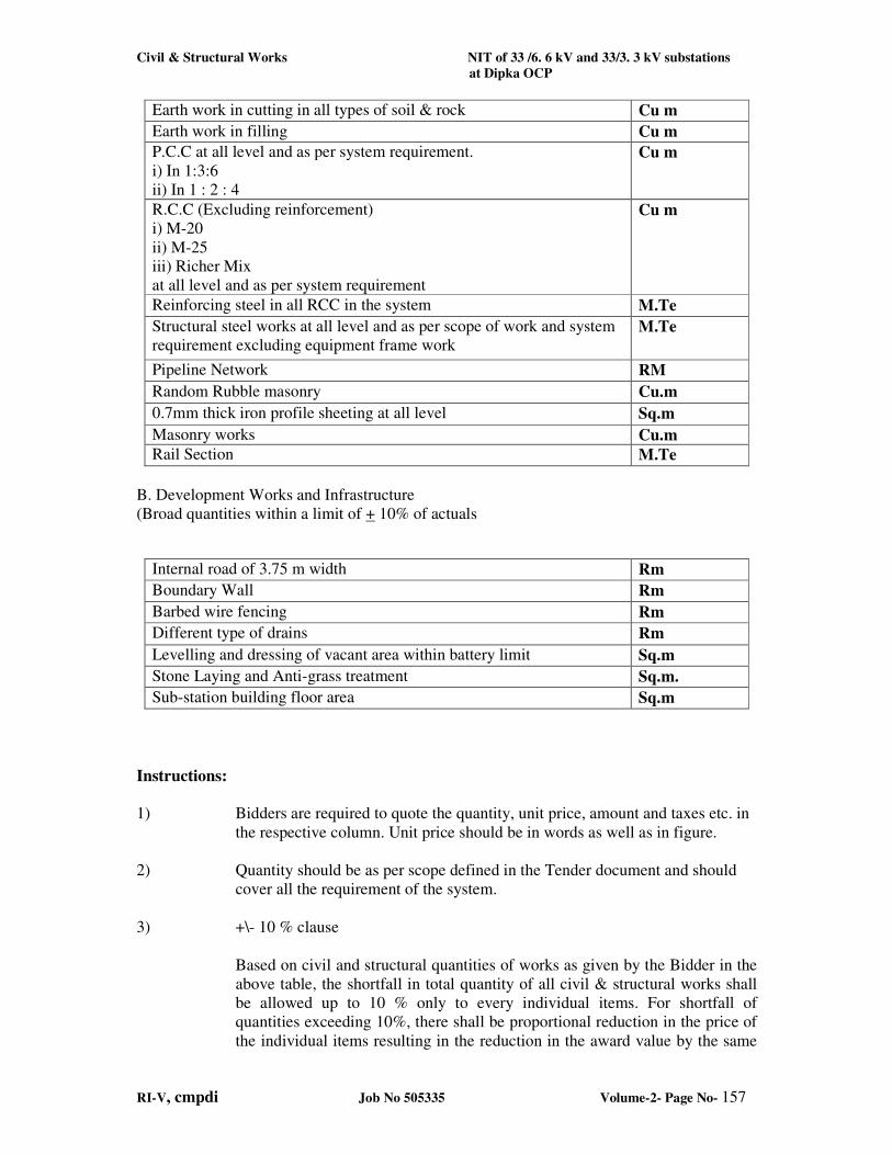
Civil & Structural Works NIT of 33 /6. 6 kV and 33/3. 3 kV substations
at Dipka OCP
RI-V, cmpdi Job No 505335 Volume-2- Page No- 157
Earth work in cutting in all types of soil & rock Cu m
Earth work in filling Cu m
P.C.C at all level and as per system requirement.
i) In 1:3:6
ii) In 1 : 2 : 4
Cu m
R.C.C (Excluding reinforcement)
i) M-20
ii) M-25
iii) Richer Mix
at all level and as per system requirement
Cu m
Reinforcing steel in all RCC in the system M.Te
Structural steel works at all level and as per scope of work and system
requirement excluding equipment frame work M.Te
Pipeline Network RM
Random Rubble masonry Cu.m
0.7mm thick iron profile sheeting at all level Sq.m
Masonry works Cu.m
Rail Section M.Te
B. Development Works and Infrastructure
(Broad quantities within a limit of + 10% of actuals
Internal road of 3.75 m width Rm
Boundary Wall Rm
Barbed wire fencing Rm
Different type of drains Rm
Levelling and dressing of vacant area within battery limit Sq.m
Stone Laying and Anti-grass treatment Sq.m.
Sub-station building floor area Sq.m
Instructions:
1) Bidders are required to quote the quantity, unit price, amount and taxes etc. in
the respective column. Unit price should be in words as well as in figure.
2) Quantity should be as per scope defined in the Tender document and should
cover all the requirement of the system.
3) +\- 10 % clause
Based on civil and structural quantities of works as given by the Bidder in the
above table, the shortfall in total quantity of all civil & structural works shall
be allowed up to 10 % only to every individual items. For shortfall of
quantities exceeding 10%, there shall be proportional reduction in the price of
the individual items resulting in the reduction in the award value by the same
Civil & Structural Works NIT of 33 /6. 6 kV and 33/3. 3 kV substations
at Dipka OCP
RI-V, cmpdi Job No 505335 Volume-2- Page No- 158
amount. Upward variation in quantity of individual items for civil & structural
works must be absorbed by contractor themselves.
4) The above items of work are to be executed strictly as per BIS/CPWD
provisions/norms.
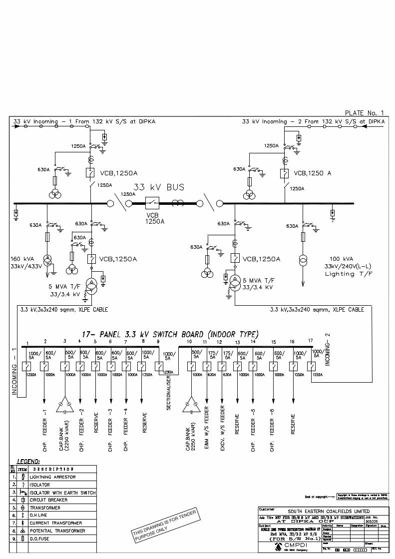
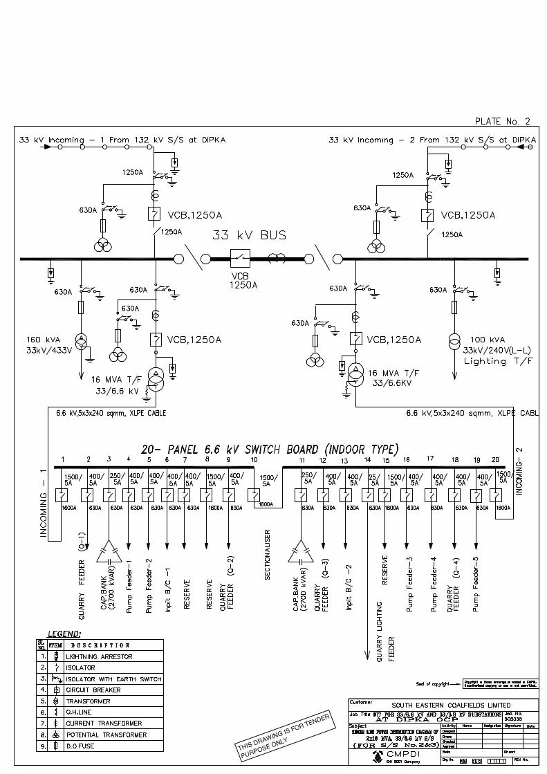
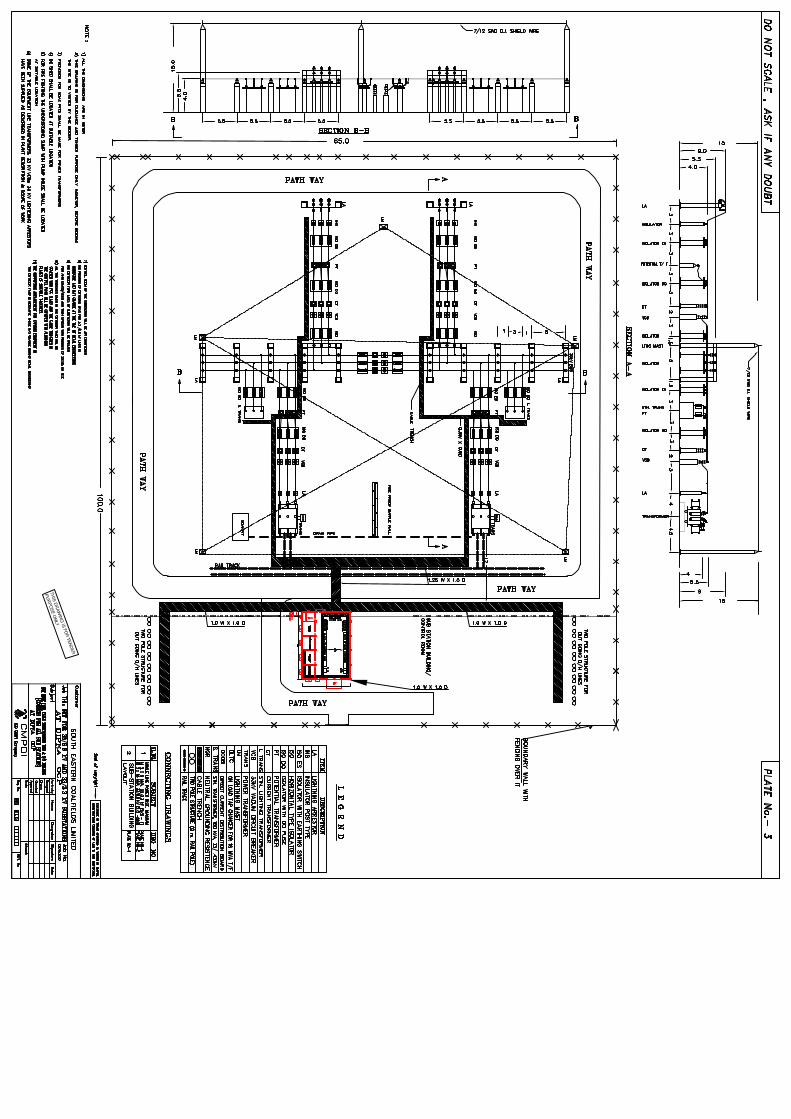
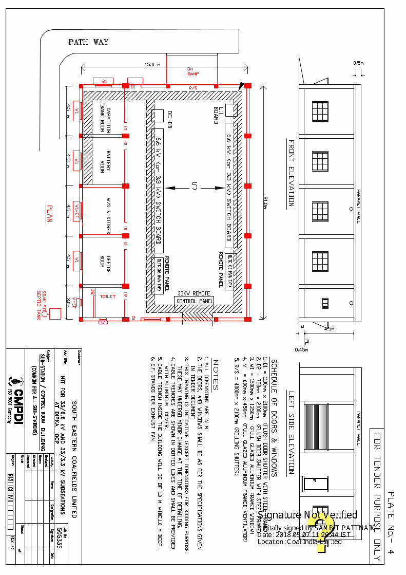
Related Documents