MECHANICS OF MATERIALS Sixth Edition Ferdinand P. Beer E. Russell Johnston, Jr. John T. DeWolf CHAPTER 3 Torsion David F. Mazurek Lecture Notes: J. Walt Oler Texas Tech University © 2012 The McGraw-Hill Companies, Inc. All rights reserved.

Welcome message from author
This document is posted to help you gain knowledge. Please leave a comment to let me know what you think about it! Share it to your friends and learn new things together.
Transcript

MECHANICS OF MATERIALS
Sixth Edition
Ferdinand P. Beer
E. Russell Johnston, Jr.
John T. DeWolf
CHAPTER
3Torsion
David F. Mazurek
Lecture Notes:
J. Walt Oler
Texas Tech University
© 2012 The McGraw-Hill Companies, Inc. All rights reserved.

MECHANICS OF MATERIALS
Sixth
Edition
Beer • Johnston • DeWolf • Mazurek
Torsional Loads on Circular Shafts
• Interested in stresses and strains of circular shafts subjected to twisting couples or torques
• Shaft transmits the torque to the generator
• Turbine exerts torque T on the shaft
© 2012 The McGraw-Hill Companies, Inc. All rights reserved. 3- 2
• Generator creates an equal and opposite torque T’
generator

MECHANICS OF MATERIALS
Sixth
Edition
Beer • Johnston • DeWolf • Mazurek
Net Torque Due to Internal Stresses
( )∫ ∫== dAdFT τρρ
• Net of the internal shearing stresses is an internal torque, equal and opposite to the applied torque,
• Although the net torque due to the shearing stresses is known, the distribution of the stresses
© 2012 The McGraw-Hill Companies, Inc. All rights reserved. 3- 3
stresses is known, the distribution of the stresses is not.
• Unlike the normal stress due to axial loads, the distribution of shearing stresses due to torsional loads can not be assumed uniform.
• Distribution of shearing stresses is statically indeterminate – must consider shaft deformations.

MECHANICS OF MATERIALS
Sixth
Edition
Beer • Johnston • DeWolf • Mazurek
• From observation, the angle of twist of the shaft is proportional to the shaft length.
L∝φ
Shaft Deformations
• When subjected to torsion, every cross-section
© 2012 The McGraw-Hill Companies, Inc. All rights reserved. 3- 4
• When subjected to torsion, every cross-section of a circular shaft remains plane and undistorted.
• Cross-sections for hollow and solid circular shafts remain plain and undistorted because a circular shaft is axisymmetric.
• Cross-sections of noncircular (non-axisymmetric) shafts are distorted when subjected to torsion.

MECHANICS OF MATERIALS
Sixth
Edition
Beer • Johnston • DeWolf • Mazurek
Shearing Strain
• Consider an interior section of the shaft. As a torsional load is applied, an element on the interior cylinder deforms into a rhombus.
© 2012 The McGraw-Hill Companies, Inc. All rights reserved. 3- 5
• Shear strain is proportional to twist and radius
maxmax and γργφγcL
c ==
LL
ρφγρφγ == or
• It follows that
MECHANICS OF MATERIALS
Sixth
Edition
Beer • Johnston • DeWolf • Mazurek
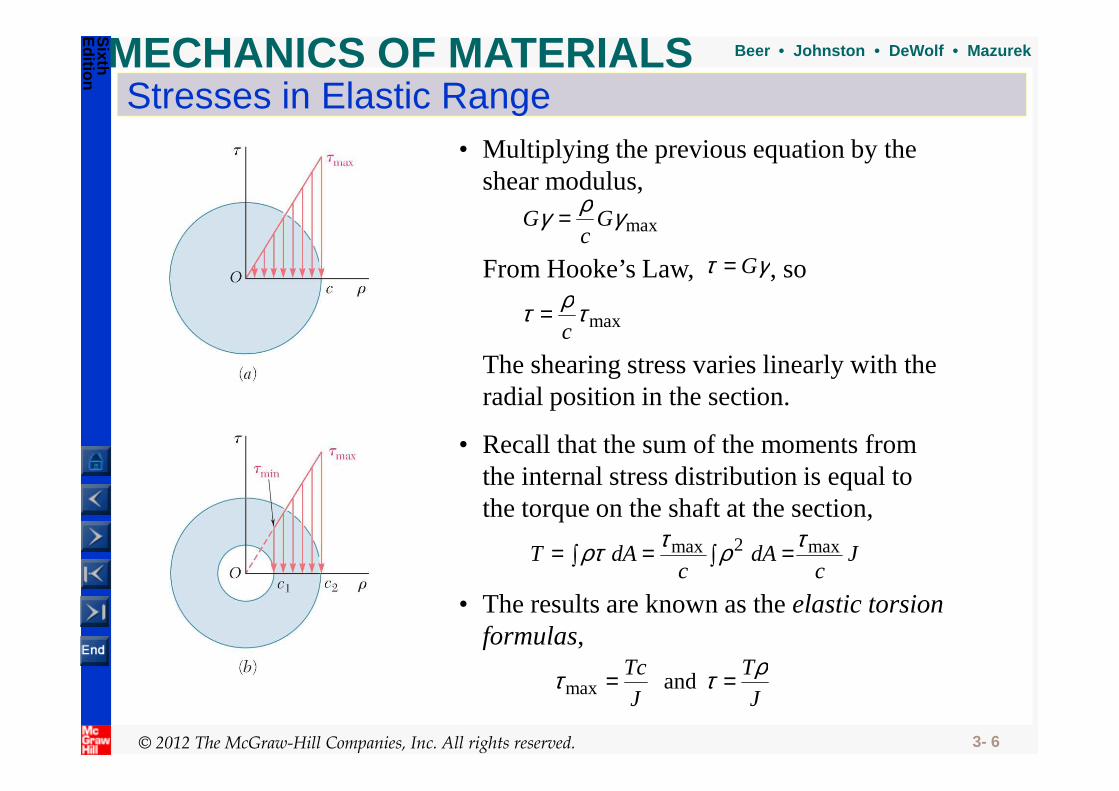
Stresses in Elastic Range• Multiplying the previous equation by the
shear modulus,
maxγργ Gc
G =
maxτρτc
=
From Hooke’s Law, γτ G= , so
The shearing stress varies linearly with the radial position in the section.
© 2012 The McGraw-Hill Companies, Inc. All rights reserved. 3- 6
Jc
dAc
dAT max2max τρτρτ ∫ =∫ ==
• Recall that the sum of the moments from the internal stress distribution is equal to the torque on the shaft at the section,
and max J
T
J
Tc ρττ ==
• The results are known as the elastic torsion formulas,
radial position in the section.

MECHANICS OF MATERIALS
Sixth
Edition
Beer • Johnston • DeWolf • Mazurek
Sample Problem 3.1
SOLUTION:
• Cut sections through shafts AB,BC, andCD and perform static equilibrium analyses to find internal torques.
• Apply elastic torsion formulas to find minimum and maximum
© 2012 The McGraw-Hill Companies, Inc. All rights reserved. 3- 7
Shaft BC is hollow with inner and outer diameters of 90 mm and 120 mm, respectively. Shafts AB and CD are solid of diameter d. For the loading shown, determine (a) the minimum and maximum shearing stress in shaft BC, (b) the required diameter d of shafts AB and CDif the allowable shearing stress in these shafts is 65 MPa.
• Given allowable shearing stress and applied torque, invert the elastic torsion formula to find the required diameter of AB and CD.
find minimum and maximum stress on shaft BC.

MECHANICS OF MATERIALS
Sixth
Edition
Beer • Johnston • DeWolf • Mazurek
Sample Problem 3.1SOLUTION:• Cut sections through shafts AB and BC
and perform static equilibrium analysis to find torque loadings.
© 2012 The McGraw-Hill Companies, Inc. All rights reserved. 3- 8
( )
CDAB
ABx
TT
TM
=⋅=
−⋅==∑
mkN6
mkN60 ( ) ( )mkN20
mkN14mkN60
⋅=
−⋅+⋅==∑
BC
BCx
T
TM

MECHANICS OF MATERIALS
Sixth
Edition
Beer • Johnston • DeWolf • Mazurek
Sample Problem 3.1• Apply elastic torsion formulas to
find minimum and maximum stress on shaft BC.
( ) [ ]ππ
• Given allowable shearing stress and applied torque, invert the elastic torsion formula to find the required diameter.
© 2012 The McGraw-Hill Companies, Inc. All rights reserved. 3- 9
( ) ( ) ( )[ ]46
4441
42
m1092.13
045.0060.022
−×=
−=−= ππccJ
( )( )
MPa2.86
m1092.13
m060.0mkN2046
22max
=×
⋅=== −J
cTBCττ
MPa7.64
mm60
mm45
MPa2.86
min
min
2
1
max
min
=
==
τ
τττ
c
c
MPa7.64
MPa2.86
min
max
=
=
τ
τ
m109.38
mkN665
3
32
42
max
−×=
⋅===
c
cMPa
c
Tc
J
Tcππτ
mm8.772 == cd

MECHANICS OF MATERIALS
Sixth
Edition
Beer • Johnston • DeWolf • Mazurek
Angle of Twist in Elastic Range• Recall that the angle of twist and maximum
shearing strain are related,
L
cφγ =max
• In the elastic range, the shearing strain and shear are related by Hooke’s Law,
JG
Tc
G== max
maxτγ
• Equating the expressions for shearing strain and
© 2012 The McGraw-Hill Companies, Inc. All rights reserved. 3- 10
• Equating the expressions for shearing strain and solving for the angle of twist,
JG
TL=φ
• If the torsional loading or shaft cross-section changes along the length, the angle of rotation is found as the sum of segment rotations
∑=i ii
ii
GJ
LTφ
MECHANICS OF MATERIALS
Sixth
Edition
Beer • Johnston • DeWolf • Mazurek
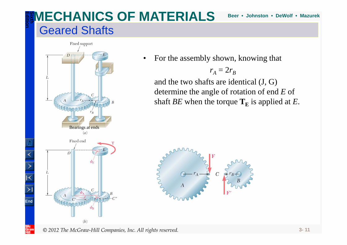
Geared Shafts
• For the assembly shown, knowing that
rA = 2rB
and the two shafts are identical (J, G) determine the angle of rotation of end E of shaft BE when the torque TE is applied at E.
© 2012 The McGraw-Hill Companies, Inc. All rights reserved. 3- 11
Bearings at ends
MECHANICS OF MATERIALS
Sixth
Edition
Beer • Johnston • DeWolf • Mazurek
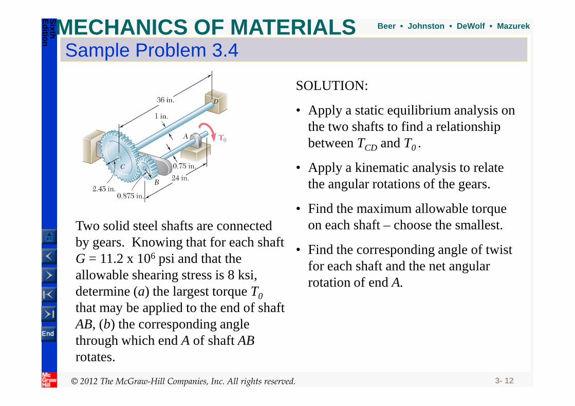
Sample Problem 3.4
SOLUTION:
• Apply a static equilibrium analysis on the two shafts to find a relationship between TCD and T0 .
• Find the maximum allowable torque
• Apply a kinematic analysis to relate the angular rotations of the gears.
© 2012 The McGraw-Hill Companies, Inc. All rights reserved. 3- 12
Two solid steel shafts are connected by gears. Knowing that for each shaft G = 11.2 x 10⁶ psi and that the allowable shearing stress is 8 ksi, determine (a) the largest torque T0
that may be applied to the end of shaft AB, (b) the corresponding angle through which end A of shaft ABrotates.
• Find the corresponding angle of twist for each shaft and the net angular rotation of end A.
• Find the maximum allowable torque on each shaft – choose the smallest.

MECHANICS OF MATERIALS
Sixth
Edition
Beer • Johnston • DeWolf • Mazurek
Sample Problem 3.4SOLUTION:
• Apply a static equilibrium analysis on the two shafts to find a relationship between TCD and T0 .
• Apply a kinematic analysis to relate the angular rotations of the gears.
© 2012 The McGraw-Hill Companies, Inc. All rights reserved. 3- 13
( )( )
0
0
8.2
in.45.20
in.875.00
TT
TFM
TFM
CD
CDC
B
=
−==
−==
∑
∑
CB
CCB
CB
CCBB
r
r
rr
φφ
φφφ
φφ
8.2
in.875.0in.45.2
=
==
=

MECHANICS OF MATERIALS
Sixth
Edition
Beer • Johnston • DeWolf • Mazurek
• Find the T0 for the maximum allowable torque on each shaft –choose the smallest.
Sample Problem 3.4• Find the corresponding angle of twist for each
shaft and the net angular rotation of end A.
( )( )( )
.in24in.lb561 ⋅== ABLTφ
© 2012 The McGraw-Hill Companies, Inc. All rights reserved. 3- 14
( )( )
( )( )
in.lb561
in.5.0
in.5.08.28000
in.lb663
in.375.0
in.375.08000
0
42
0max
0
42
0max
⋅=
==
⋅=
==
T
Tpsi
J
cT
T
Tpsi
J
cT
CD
CD
AB
AB
π
π
τ
τ
inlb5610 ⋅=T
( )( )( ) ( )
( )( )( ) ( )
( )oo
/
oo
o
642
/
o
642
/
2.2226.8
26.895.28.28.2
95.2rad514.0
psi102.11in.5.0
.in24in.lb5618.2
2.22rad387.0
psi102.11in.375.0
.in24in.lb561
+=+=
===
==
×⋅==
==
×⋅==
BABA
CB
CD
CDDC
AB
ABBA
GJ
LT
GJ
LT
φφφ
φφ
φ
φ
π
π
o48.10=Aφ

MECHANICS OF MATERIALS
Sixth
Edition
Beer • Johnston • DeWolf • Mazurek
• Given the shaft dimensions and the applied torque, we would like to find the torque reactions at A and B.
Statically Indeterminate Shafts
• From a free-body analysis of the shaft,
which is not sufficient to find the end torques. The problem is statically indeterminate.
ftlb90 ⋅=+ BA TT
© 2012 The McGraw-Hill Companies, Inc. All rights reserved. 3- 15
The problem is statically indeterminate.
ftlb9012
21 ⋅=+ AA TJL
JLT
• Substitute into the original equilibrium equation,
ABBA T
JL
JLT
GJ
LT
GJ
LT
12
21
2
2
1
121 0 ==−=+= φφφ
• Divide the shaft into two components which must have compatible deformations,
MECHANICS OF MATERIALS
Sixth
Edition
Beer • Johnston • DeWolf • Mazurek
Design of Transmission Shafts
• Principal transmission shaft performance specifications are:
- power- speed
• Determine torque applied to shaft at specified power and speed,
ω
ωP
T
TP
=
=
• Unit conversions- Power
© 2012 The McGraw-Hill Companies, Inc. All rights reserved. 3- 16
- Power- 1 W = 1 Nm/s- 1 hp = 550 lb-ft/s
- Speed- 1Hz = 1 rev/s = 2π rad/s- 1 rpm = 1 rev/min = 2π/60 rad/s
MECHANICS OF MATERIALS
Sixth
Edition
Beer • Johnston • DeWolf • Mazurek
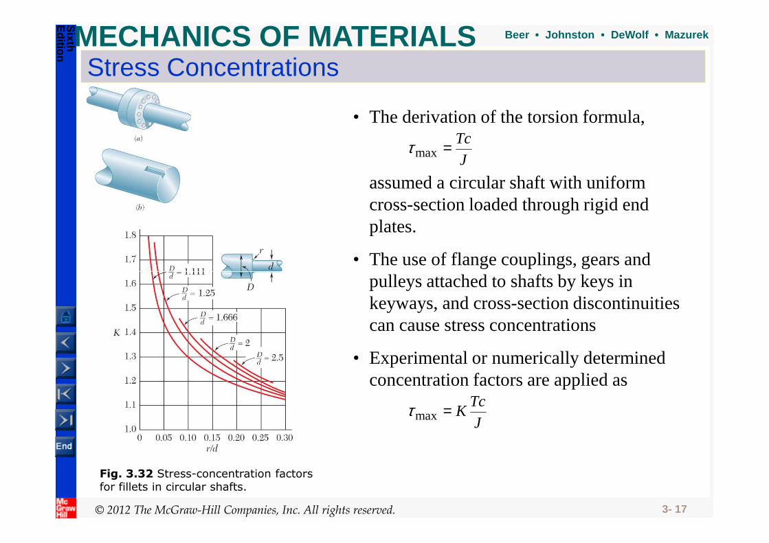
Stress Concentrations
• The derivation of the torsion formula,
assumed a circular shaft with uniform cross-section loaded through rigid end plates.
J
Tc=maxτ
• The use of flange couplings, gears and pulleys attached to shafts by keys in
© 2012 The McGraw-Hill Companies, Inc. All rights reserved. 3- 17
J
TcK=maxτ
• Experimental or numerically determined concentration factors are applied as
pulleys attached to shafts by keys in keyways, and cross-section discontinuities can cause stress concentrations
Fig. 3.32 Stress-concentration factors for fillets in circular shafts.