[1] National Institute of Science & Technology Siddhartha B N & I Mukhopadhyay B. TECH FINAL PROJECT PRESENTATION 2013-2014 Sunil Kumar Sahu (EIE201010178) & Asish Kumar Gouda (EIE 201018112) PROJECT ID - 3165 ASISH KUMAR GOUDA Roll # EIE 201018112 SUNIL KUMAR SAHU Roll # EIE 201010178 Battery Management System Using LabVIEW Under the guidance of Mr. Satyabrata Das PRESENTED BY

Welcome message from author
This document is posted to help you gain knowledge. Please leave a comment to let me know what you think about it! Share it to your friends and learn new things together.
Transcript
[1]
Nati
onal In
stit
ute
of
Sci
en
ce &
Tech
nolo
gy
Siddhartha B N & I Mukhopadhyay
B. TECH FINAL PROJECT PRESENTATION 2013-2014
Sunil Kumar Sahu (EIE201010178) & Asish Kumar Gouda (EIE 201018112)
PROJECT ID - 3165
ASISH KUMAR GOUDA Roll # EIE 201018112SUNIL KUMAR SAHU Roll # EIE 201010178
Battery Management System Using LabVIEW
Under the guidance of Mr. Satyabrata Das
PRESENTED BY

[2]
Nati
onal In
stit
ute
of
Sci
en
ce &
Tech
nolo
gy
Siddhartha B N & I Mukhopadhyay
B. TECH FINAL PROJECT PRESENTATION 2013-2014
Sunil Kumar Sahu (EIE201010178) & Asish Kumar Gouda (EIE 201018112)
Contents 1. Introduction
2. Initial Preparation
3. Serial communication
4. RS-232 Standard
5. DB 9 PIN CONNECTOR
6. TEMPERATURE SENSOR (LM35)
7. MAX 232
8. POWER SUPPLY
9. PIC16F877A(40/44-Pin Enhanced Flash Micro controllers)
10. HARDWARE DIAGRAM
11. LabVIEW CODE(BLOCK DIAGRAM)
12. LabVIEW CODE(FRONT PANNEL )
13. Conclusion

[3]
Nati
onal In
stit
ute
of
Sci
en
ce &
Tech
nolo
gy
Siddhartha B N & I Mukhopadhyay
B. TECH FINAL PROJECT PRESENTATION 2013-2014
Sunil Kumar Sahu (EIE201010178) & Asish Kumar Gouda (EIE 201018112)
Introduction
3
• This project deals with developing a universal battery management system that can read battery voltage, current and temperature. The two major components of the system are hardware and software. The software uses LabVIEW as a platform to interface with the hardware for data acquisition.
• The LabVIEW GUI is primarily divided into two portions, the block diagram and the front panel. The block diagram allows the user to perform various graphical coadings. The display panel presents the experimental data on a waveform.

[4]
Nati
onal In
stit
ute
of
Sci
en
ce &
Tech
nolo
gy
Siddhartha B N & I Mukhopadhyay
B. TECH FINAL PROJECT PRESENTATION 2013-2014
Sunil Kumar Sahu (EIE201010178) & Asish Kumar Gouda (EIE 201018112)
Initial Preparation
1. Install the Lab-VIEW software on to the PC with all the tool kit and device drivers.
2. Activate the Lab-VIEW using key and check for the installed tool kits.
3. Initialize the serial port using dedicated links and pallets.
4. Connect the hardware devices and select appropriate communication port.
5. Switch on the hardware and play the software.
4
[5]
Nati
onal In
stit
ute
of
Sci
en
ce &
Tech
nolo
gy
Siddhartha B N & I Mukhopadhyay
B. TECH FINAL PROJECT PRESENTATION 2013-2014
Sunil Kumar Sahu (EIE201010178) & Asish Kumar Gouda (EIE 201018112)
5
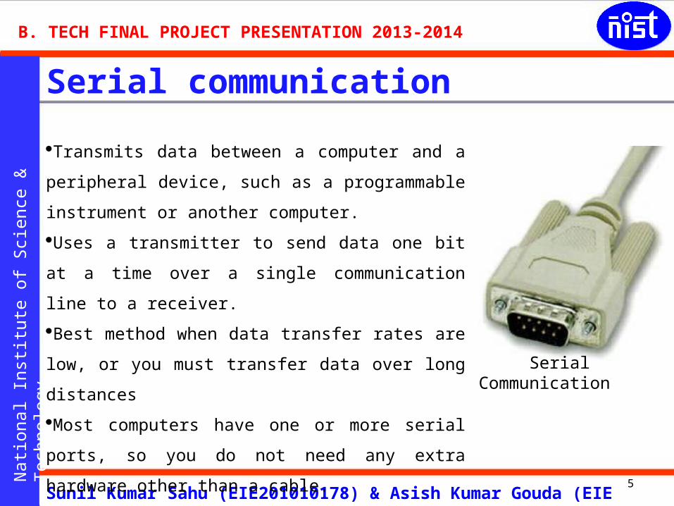
Serial communication
Transmits data between a computer and a peripheral
device, such as a programmable instrument or another
computer.
Uses a transmitter to send data one bit at a time over a
single communication line to a receiver.
Best method when data transfer rates are low, or you
must transfer data over long distances
Most computers have one or more serial ports, so you
do not need any extra hardware other than a cable.
Serial Communication

[6]
Nati
onal In
stit
ute
of
Sci
en
ce &
Tech
nolo
gy
Siddhartha B N & I Mukhopadhyay
B. TECH FINAL PROJECT PRESENTATION 2013-2014
Sunil Kumar Sahu (EIE201010178) & Asish Kumar Gouda (EIE 201018112)
6
RS-232 Standard
Limited to point-to-point connections between PC serial ports and devices. The RS
232 standard defines different voltage level corresponding to Logic 1 & Logic 0.
Logic 1 is defined as negative voltage & Logic 0 is defined as positive voltage.
Valid voltages are in range of plus or minus 3 to 15 Volts for Logic 0 & Logic 1.
correspondingly.

[7]
Nati
onal In
stit
ute
of
Sci
en
ce &
Tech
nolo
gy
Siddhartha B N & I Mukhopadhyay
B. TECH FINAL PROJECT PRESENTATION 2013-2014
Sunil Kumar Sahu (EIE201010178) & Asish Kumar Gouda (EIE 201018112)
7
The DB9 (originally DE-9) connector is an
analog 9-pin plug of the D-Sub miniature
connector family (D-Sub or Sub-D). The
DB9 connector is mainly used for serial
connections, allowing for the asynchronous
transmission of data as provided for
standard RS-232 (RS-232C).
DB 9 PIN CONNECTOR PIN DESCRIPTION:
[8]
Nati
onal In
stit
ute
of
Sci
en
ce &
Tech
nolo
gy
Siddhartha B N & I Mukhopadhyay
B. TECH FINAL PROJECT PRESENTATION 2013-2014
Sunil Kumar Sahu (EIE201010178) & Asish Kumar Gouda (EIE 201018112)
8
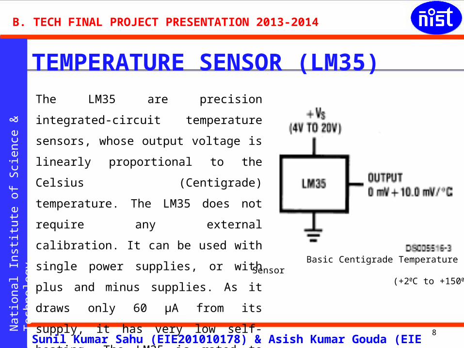
The LM35 are precision integrated-circuit
temperature sensors, whose output voltage
is linearly proportional to the Celsius
(Centigrade) temperature. The LM35 does
not require any external calibration. It can
be used with single power supplies, or with
plus and minus supplies. As it draws only
60 μA from its supply, it has very low self-
heating. The LM35 is rated to operate over
a −55° to +150°C temperature range.
TEMPERATURE SENSOR (LM35)
Basic Centigrade Temperature Sensor (+20C to +1500)

[9]
Nati
onal In
stit
ute
of
Sci
en
ce &
Tech
nolo
gy
Siddhartha B N & I Mukhopadhyay
B. TECH FINAL PROJECT PRESENTATION 2013-2014
Sunil Kumar Sahu (EIE201010178) & Asish Kumar Gouda (EIE 201018112)
9
MAX 232The MAX232 is an integrated circuit that converts signals from an RS-232 serial
port to signals suitable for use in TTL compatible digital logic circuits. The MAX232
is a dual driver/receiver. C3
C4DB9-connectorMicro-controller
[10]
Nati
onal In
stit
ute
of
Sci
en
ce &
Tech
nolo
gy
Siddhartha B N & I Mukhopadhyay
B. TECH FINAL PROJECT PRESENTATION 2013-2014
Sunil Kumar Sahu (EIE201010178) & Asish Kumar Gouda (EIE 201018112)
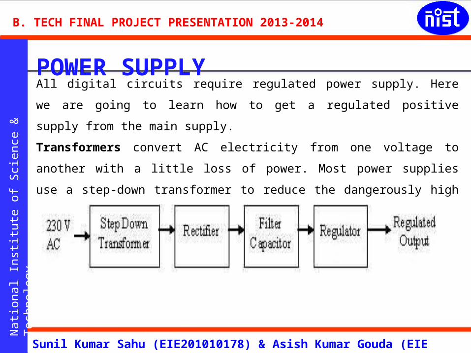
POWER SUPPLYAll digital circuits require regulated power supply. Here we are going to learn how
to get a regulated positive supply from the main supply.
Transformers convert AC electricity from one voltage to another with a little loss
of power. Most power supplies use a step-down transformer to reduce the
dangerously high voltage to a safer low voltage. Voltage regulator is a device
which converts varying input voltage into a constant regulated output voltage.
[11]
Nati
onal In
stit
ute
of
Sci
en
ce &
Tech
nolo
gy
Siddhartha B N & I Mukhopadhyay
B. TECH FINAL PROJECT PRESENTATION 2013-2014
Sunil Kumar Sahu (EIE201010178) & Asish Kumar Gouda (EIE 201018112)
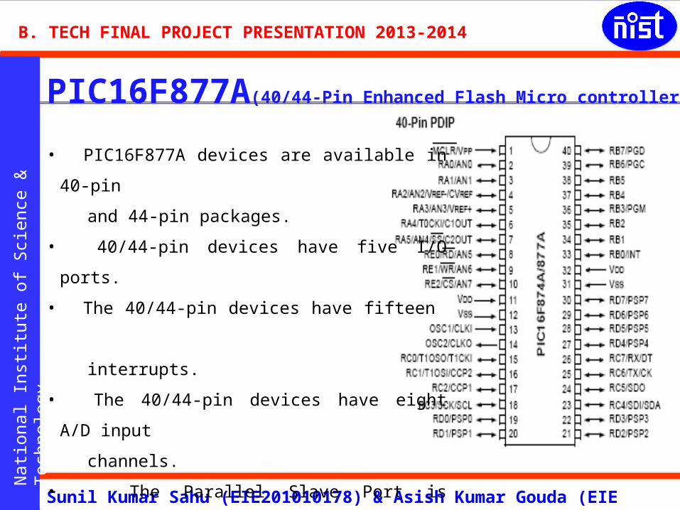
PIC16F877A(40/44-Pin Enhanced Flash Micro controllers)
• PIC16F877A devices are available in 40-pin
and 44-pin packages.
• 40/44-pin devices have five I/O ports.
• The 40/44-pin devices have fifteen
interrupts.
• The 40/44-pin devices have eight A/D input
channels.
• The Parallel Slave Port is implemented only
on the 40/44-pin devices.
[12]
Nati
onal In
stit
ute
of
Sci
en
ce &
Tech
nolo
gy
Siddhartha B N & I Mukhopadhyay
B. TECH FINAL PROJECT PRESENTATION 2013-2014
Sunil Kumar Sahu (EIE201010178) & Asish Kumar Gouda (EIE 201018112)
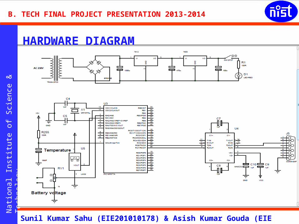
HARDWARE DIAGRAM
[13]
Nati
onal In
stit
ute
of
Sci
en
ce &
Tech
nolo
gy
Siddhartha B N & I Mukhopadhyay
B. TECH FINAL PROJECT PRESENTATION 2013-2014
Sunil Kumar Sahu (EIE201010178) & Asish Kumar Gouda (EIE 201018112)
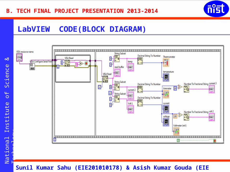
LabVIEW CODE(BLOCK DIAGRAM)
[14]
Nati
onal In
stit
ute
of
Sci
en
ce &
Tech
nolo
gy
Siddhartha B N & I Mukhopadhyay
B. TECH FINAL PROJECT PRESENTATION 2013-2014
Sunil Kumar Sahu (EIE201010178) & Asish Kumar Gouda (EIE 201018112)
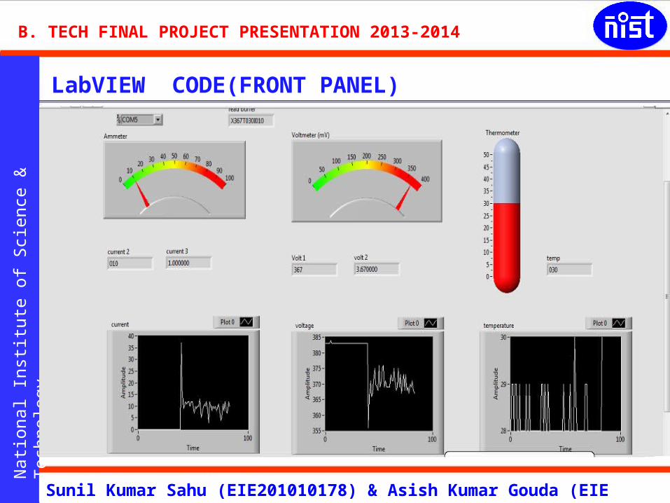
LabVIEW CODE(FRONT PANEL)

[15]
Nati
onal In
stit
ute
of
Sci
en
ce &
Tech
nolo
gy
Siddhartha B N & I Mukhopadhyay
B. TECH FINAL PROJECT PRESENTATION 2013-2014
Sunil Kumar Sahu (EIE201010178) & Asish Kumar Gouda (EIE 201018112)
CONCLUSION
15
1. A battery management system is essentially the “brain” of a battery pack;
it measures and reports crucial information for the operation of the battery
and also protects the battery from damage in a wide range of operating
conditions.
2. The most important function that a battery management system performs
is cell protection.
3. Lithium ion battery cells have critical design issues; if you overcharge
them you can damage them and cause overheating and even explosion,
so it's important to have a battery management system to provide
overvoltage protection .
[16]
Nati
onal In
stit
ute
of
Sci
en
ce &
Tech
nolo
gy
Siddhartha B N & I Mukhopadhyay
B. TECH FINAL PROJECT PRESENTATION 2013-2014
Sunil Kumar Sahu (EIE201010178) & Asish Kumar Gouda (EIE 201018112)
16
Related Documents

![MiCOKit-3165 Development Kit Hardware Manual€¦ · MiCOKit-3165 Development Kit Hardware Manual [Page 1] RM0003EN Version Record Date Version Update content 6-23-2016 V1.0 Initial](https://static.cupdf.com/doc/110x72/605a3e6971a634011846e8e3/micokit-3165-development-kit-hardware-micokit-3165-development-kit-hardware-manual.jpg)


