1 Department of Pediatric Dentistry and Orthodontics Department of Pediatric Dentistry and Orthodontics Department of Pediatric Dentistry and Orthodontics Department of Pediatric Dentistry and Orthodontics DIVISION OF PEDIATRIC DENTISTRY DIVISION OF PEDIATRIC DENTISTRY DIVISION OF PEDIATRIC DENTISTRY DIVISION OF PEDIATRIC DENTISTRY 312 POS PRE-CLINICAL MANUAL

Welcome message from author
This document is posted to help you gain knowledge. Please leave a comment to let me know what you think about it! Share it to your friends and learn new things together.
Transcript
1
Department of Pediatric Dentistry and OrthodonticsDepartment of Pediatric Dentistry and OrthodonticsDepartment of Pediatric Dentistry and OrthodonticsDepartment of Pediatric Dentistry and Orthodontics
DIVISION OF PEDIATRIC DENTISTRYDIVISION OF PEDIATRIC DENTISTRYDIVISION OF PEDIATRIC DENTISTRYDIVISION OF PEDIATRIC DENTISTRY
312 POS
PRE-CLINICAL MANUAL

2
TABLE OF CONTENTS
Pages
List of Session
Introduction ………….……………………………………………………………………….
Morphology of Primary Molars ………………………………………………………………..
Maxillary First Molars ………………………………………………………………..
Mandibular First Molars ……………………………………………………………….
Maxillary Second Molars …………….…………………………………………………
Mandibular Second Molars …………………………………………………………….
Glossary …………………………………………………………………………………………
Primary Versus Permanent Principles of Cavity Preparation ….…………………………………
Class I – Cavity Preparation …………………………………………………………….
Class I – Cavity Preparation Tooth No. 54 ……….................………………………….Class I – Cavity Preparation Tooth No. 84…………..................………………………..
Modified Class I – Cavity Preparation Tooth No. 55 OL ……………………………
Class II – Cavity Preparation Tooth No. 65 MO …………………………….........Class II – Cavity Preparation Tooth No. 85 MO ………………........…………….Class II – Cavity Preparation Tooth No. 75 DO ……………….................…………….
Forming and Placing a T-Band Matrix ………......................………………………….. Removing the T-Band Matrix …………………………………………………………..
Class III – Cavity Preparation –Conventional (Simple) Class III Tooth No. 52 D ……………..
Class III – Slot Preparation Tooth No. 61 M (Lingual Access) …………………………………
Modified Class III (Dovetail) Tooth No. 51 M (Lingual Access) ……………………………….
Full Crown Preparation of Incisors Tooth No. 62 ………………………………………….......
Celluloid (Strip) Crown Form Preparation ……………………………………………………..
Resin Crown Placement ………………………………………………………………………….
Stainless Steel Crown Preparation Tooth No. 75 ……………………………………………….
Formocresol Pulpotomy ………………………………………………………………………….
Application of Topical Fluoride Gel …………………………………………………………….
Application of Sealant to Occlusal Pits and Fissures ……………………………………………
1
3
3
3
4
4
5
9 10 12 13
10
14 17 20
23 25
26
27
28
29
30
31
32
35
39
40

3

4
INTRODUCTION
The primary goals of Pediatric Dentistry include the diagnosis and prevention of disease, the preservation of the
natural dentition and the restoration of health, function and esthetics of stomatognathic system.
The primary function of the laboratory is the development of psychomotor skills of dental students. The
psychomotor skills must be highly developed in order to provide quality care for children.
Due to the high degree of skill required, disappointments and frustrations may occur during the process of
learning and development. Some students, for example, will need to repeat various projects. However, the pre-
clinical laboratory is the place where mistakes can occur without damage to the patient, and where sills can be
developed to a high level of proficiency.
In order to maximize the benefits of each laboratory session, students will be expected to study this laboratory
manual in preparation for each project in advance.
Course Objectives:
Upon completion of this course the student should be able to:
• Describe morphological characteristics of primary dentition (1.3)
• Prepare cavities in primary teeth and place restorations effectively so as to restore anatomical landmarks
(1.3)
• Diagnose dental caries in primary dentition (2.1)
• Explain preventive measures against dental diseases in children. (2.1)
• Preserve the natural dentition and restore health, function, and esthetics of decayed primary dentition (1.3)
• Demonstrate manual dexterity required to provide quality dental care for children (5.1)
Attendance:
Attendance in the laboratory is required and promptness is expected. Unexcused absences in excess of school
policy will result in a grade of “F”. Student will be expected to remain at work in the laboratory for the entire
period.
Supplies:
Supplies will be dispensed only during laboratory hours.
Daily Projects:
A unit will be assigned to you in the laboratory by the course director and each project supervised by faculty
members. She/he will be available to help you with any problems you may have during the course of your
work. Follow the instructor’s suggestion for improving the project you are working on. Your instructor will
probably be your best learning resource.
Evaluation
1. Satisfactory completion of all projects - 20%
2. Neatness of cubicle - 5%
3. Quizzes - 5%
4. Midterm Examination - 10%
5. Final Examination - 10%

5
UPPER
LOWER

6
MORPHOLOGY OF PRIMARY MOLARS
Maxillary First Molars:
Fig. 1
These molars exhibit a trapezoidal coronal outline when viewed from the occlusal aspect. Their occlusal tables
are divided into a buccal and lingual half by deep central developmental groove which runs mesiodistally
connecting the mesial, central and distal fossae. They have four cusps: mesiolingual, mesiobuccal, distobuccal
and distolingual, in decreasing order of size and development. A three-cusped form sometimes occurs, when the
lingual developmental groove, and hence the distolingual cusp, is missing. The crown of these molars have a
pronounced bulge near the cervix on the buccal and lingual surfaces. This bulge is particularly well developed
on the mesiobuccal side and is sometimes referred to as the molar tubercle of Zuckerkandl. The crown
converges lingually from its wide cervical bulge to the narrow occlusal surface.
Three or four pulp horns exist corresponding to each cusp. The mesiobuccal pulp horn is the largest. The
mesiobuccal pulp horn is 0.8 – 1.83 mm below the cusp tip, the distobuccal is 1.3 – 2.11 mm while the lingual
pulp horns is 1.2 – 2.05 mm. There are three slender roots, two buccal and one palatal and unlike the permanent
molars they arise directly from the cervix and not from a common root trunk. These roots are the palatal,
mesiobuccal and distobuccal, in decreasing order of size and divergence. These divergent roots tend to converge
again at their apices giving them the appearance of a crane grab.
Mandibular First Molars:
Fig. 2
The coronal outline of these molars is irregularly quadrilateral with a longer mesiodistal diameter than
buccolingual. The tooth has four cusps, mesiolingual, mesiobuccakl, distobuccal and distolingual, in
descending order of size and development. The buccal cusps are lingually inclined, and they are separated only
by a shallow depression rather than a developmental groove as found in the other mandibular molars. The two
mesial cusps are joined by a prominent transverse ride of enamel called the “buccolingual crest”. This ridge
divides the occlusal table into a small mesial fossa and a longer one distally. The combined mesiodistal width
of the lingual cusps is less than that of the buccal surface exhibit a well-developed protuberance, which is a
feature of the primary first molars, and is referred to as the “molar tubercle of Zukerkandl”.

7
There are four pulp horns with one pulp horn beneath each cusp. Both the buccal and lingual mesial pulp horns
are 3.3 mm to the cusp tips, while the distal pulp horns are 3.5 mm to the cusp tips. There are two flattened
roots, with two root canals, a longer root mesially and a shorter one distally.
Maxillary Second Molars:
Fig. 3
These molars are an exact replica of the maxillary 1st permanent molars, but are smaller in size. They exhibit
rhomboidal occlusal outline with four distinct cusps: mesiolingual, mesiobuccal, distolingual and distobucal, in
decreasing order of size and development. In approximately 50-75% of population, a fifth cusp is found on the
lingual surface of the mesiolingual cusp and is known as the cusp of carabelli. The buccal cusps are separated
by a distinct lingual developmental groove which extends to the lingual surface. A prominent oblique ridge
connects the mesiolingual and distobuccal cusps. There are three pits occlusally: a deep distal pit, a central pit
and a shallow mesial pit. There may be four or five pulp horns corresponding to the cusp tips: the mesiobuccal
pulp horn is the largest followed by mesiolingual, the distobuccal and the distolingual in a descending order.
The mesiobuccal pulp horn is 4 mm below the cusp tip while the distobuccal pulp horn is 4.3 mm. There are
two buccal roots and one palatal each containing one-root canal. The palatal root is the largest followed by the
mesiobuccal and the distobuccal is the smallest.
Mandibular Second Molars: D
Fig. 4
These molars are similar to the lower permanent first molar in its general morphology. They exhibit a
comparatively regular rectangular outline from an occlusal aspect. They have five cusps, two lingual cusps of
equal sizes and three buccal cusps: distobuccal, mesiobuccal and distal in descending order of size and
development. There are three pits occlusally: a deep and well defined central pit, a mesial pit, and a rather
undefined distal pit. There are five pulp horns corresponding to the five cusps tips. The mesiobuccal pulp horn
is the largest extending to about 4.0 mm below the cusp tip while the distobuccal pulp horn is 4.3 mm. There
are two widely divergent roots, mesially and distally, both flattened in a mesiodistal direction. The mesial root
is longer rectangular in shape and contains one or two roots canals while the distal is slightly shorter and
contains one root canal.
8
GLOSSARY OF RESTORATIVE TERMINOLOGY APPROVED
BY AMERICAN ACADEMY OF PEDIATRIC DENTISTRY
AXIAL WALL : The inner perpendicular wall of a prepared cavity covering the proximal
portion of the pulp tissue.
CAVOSURFACE ANGLE: The angle formed by the cavity walls and the external surface of the tooth.
DOVETAIL : The interlocking occlusal extension of a prepared cavity.
ISTHMUS : The constricted passage connecting two larger portions of a prepared cavity,
the occlusal dovetail and the proximal box.
LINE ANGLE : The angle formed by the junction of two walls of a prepared cavity.
POINT ANGLE : The angle formed by the junction of three walls of a prepared cavity.
PROXIMAL BOX : The mesial or distal proximal extension of a prepared cavity.
PULPAL FLOOR : The inner horizontal floor of a prepared cavity covering the occlusal portion
of the pulp tissue.
PULPOTOMY : The surgical removal (amputation) of the entire pulp contents of the coronal
portion of a vital tooth to the entrance of the root canal(s) leaving the tissue
in the canal(s) intact.
RESISTNACE FORM : That form of the cavity which protects the filling material and the remaining
dental structure against fracture by the forces of mastication.
RESTORATION : The repairing, reforming or restoring of a tooth to its normal morphologic
size, shape and function.

9
PRIMARY VERSUS PERMANENT
PRINCIPLES OF CAVITY PREPARATION
CLASS I – CAVITY PREPARATION
Class I occlusal cavity preparations for incipient lesions in primary teeth are basically like those for permanent
teeth. Certain modifications are implemented and are dictated mainly by morphological and developmental
differences, such as:
1. Relative size of the teeth.
2. Thickness of enamel and dentin.
3. Size and location of the pulp.
4. Complexity of the occlusal surface.
Modification for Class I Cavity Preparations:
1. Less depth in pulpal direction, 1-1.25 mm (measured from the cavosurface margin), to avoid the
highly positioned pulp horns.
2. Rounded pulpal floor to prevent pulp exposure at the bucco and lingo-pulpal line angles.
Modifications for Class II Cavity Preparations:
1. The broad and flat contact area in primary molars mandate a wider extension of the proximal box to
attain a self-cleansing area.
2. Rounded (convex) axial wall to avoid pulpal exposure.
3. Axio-pulpal line angle is rounded to reduce stresses from mastication.
4. The bucco-and-lingo-gingival line angle is slightly rounded.
5. No bevel is needed gingivally since enamel rods of primary teeth incline occlusally in the cervical
third.
10
CLASS I: CAVITY PREPARATION TOOTH NO. 54
Instrumentation:
Mirror
Explorer
No. 330 F.G. carbide bur
No. 169L F.G. carbide bur
No. 4R F.G. carbide bur
Low and high speed hand pieces
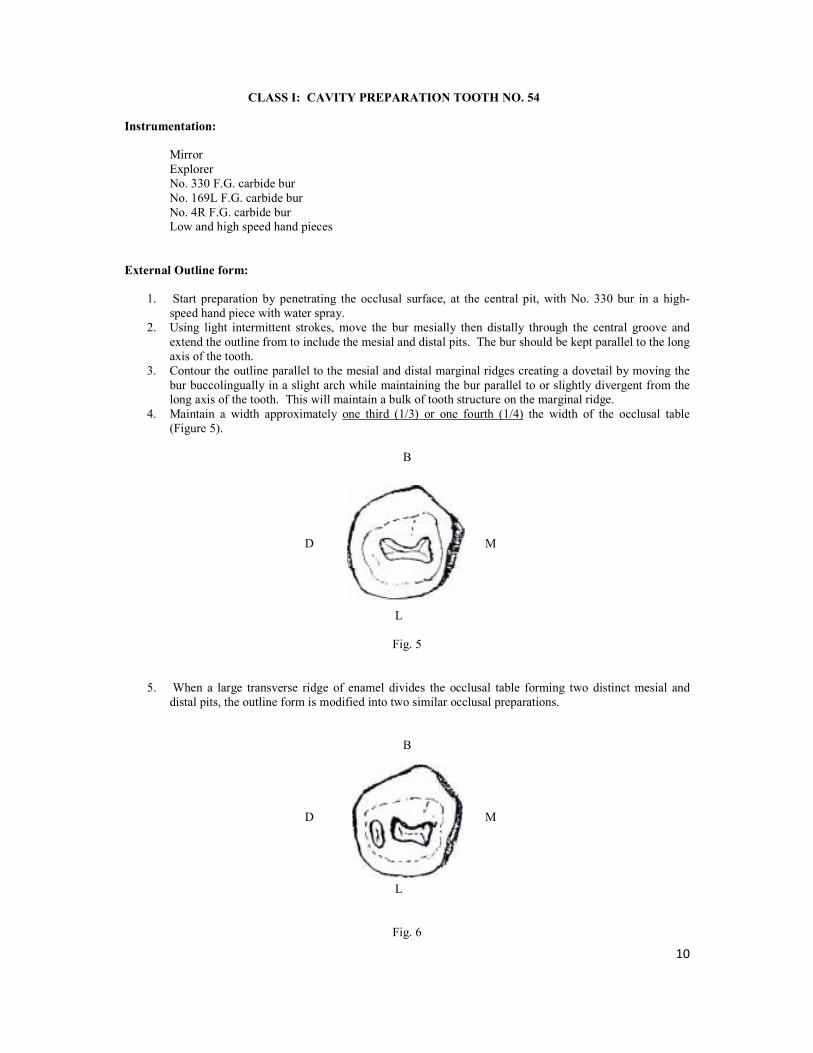
External Outline form:
1. Start preparation by penetrating the occlusal surface, at the central pit, with No. 330 bur in a high-
speed hand piece with water spray.
2. Using light intermittent strokes, move the bur mesially then distally through the central groove and
extend the outline from to include the mesial and distal pits. The bur should be kept parallel to the long
axis of the tooth.
3. Contour the outline parallel to the mesial and distal marginal ridges creating a dovetail by moving the
bur buccolingually in a slight arch while maintaining the bur parallel to or slightly divergent from the
long axis of the tooth. This will maintain a bulk of tooth structure on the marginal ridge.
4. Maintain a width approximately one third (1/3) or one fourth (1/4) the width of the occlusal table
(Figure 5).
B
D M
L
Fig. 5
5. When a large transverse ridge of enamel divides the occlusal table forming two distinct mesial and
distal pits, the outline form is modified into two similar occlusal preparations.
B
D M
L
Fig. 6

11
Internal Outline Form:
1. Establish a depth of 1-1.25 mm (measured from the cavosurface margin) throughout the preparation.
The No. 330 bur is a good depth marker.
2. Slightly round the pulpal floor through tilting the No. 330 bur slightly in a buccal and lingual
direction. This action will result in buccal and lingual walls that converge occlusally. This
convergence aids in retention of the restorative materials.
3. Through the previous action, all the internal line angles would be rounded. The round line angles are
easier areas to condense amalgam into, plus they reduce internal stress on the amalgam restoration.
4. Establish a sharp cavosurface angle (900) of the lateral wall using the No. 169L bur. (Care should be
taken so that the bur does not touch the pulpal floor). This sharp angle facilitates carving and polishing
and hence reduce the marginal failure (Figure 7).
5. In clinical situation, any caries left, at this stage, can be removed with spoon excavator or with a No. 4
round bur in slow speed hand piece.
Fig. 7
12
CLASS I: CAVITY PREPARATION TOOTH NO. 84
Instrumentation:
Mirror
Explorer
No. 330 F.G. carbide bur
No. 169L F.G carbide bur
No. 4R F.G. carbide bur
Low and high speed hand pieces
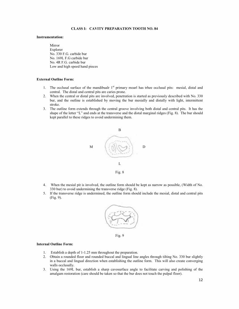
External Outline Form:
1. The occlusal surface of the mandibualr 1st primary moarl has trhee occlusal pits: mesial, distal and
central. The distal and central pits are caries prone.
2. When the central or distal pits are involved, penetration is started as previously described with No. 330
bur, and the outline is established by moving the bur mesially and distally with light, intermittent
stroke.
3. The outline form extends through the central groove involving both distal and central pits. It has the
shape of the letter “L” and ends at the transverse and the distal marginal ridges (Fig. 8). The bur should
kept parallel to these ridges to avoid undermining them.
B
M D
L
Fig. 8
4. When the mesial pit is involved, the outline form should be kept as narrow as possible, (Width of No.
330 bur) to avoid undermining the transverse ridge (Fig. 8).
5. If the transverse ridge is undermined, the outline form should include the mesial, distal and central pits
(Fig. 9).
Fig. 9
Internal Outline Form:
1. Establish a depth of 1-1.25 mm throughout the preparation.
2. Obtain a rounded floor and rounded buccal and lingual line angles through tilting No. 330 bur slightly
in a buccal and lingual direction when establishing the outline form. This will also create converging
walls occlusally.
3. Using the 169L bur, establish a sharp cavosurface angle to facilitate carving and polishing of the
amalgam restoration (care should be taken so that the bur does not touch the pulpal floor).

13
MODIFIED CLASS I – CAVITY PREPARATION TOOTH NO. 55 OL
Instrumentation:
Mirror
Explorer
Enamel Hatchet 13-14
Bin Angle Chisel 17-18
No. 330 F.G. carbide bur
No. 169L F.G. carbide bur
No. 4R F.G. carbide bur
Low and high speed hand pieces
External Outline Form:
1. When both the distal and lingual pits are involved with caries, a Class I cavity preparation on the distal
fossa should be extended lingually to involve the lingual groove and form a two-surface restoration
(Modified Class I).
2. Start preparation using No. 330 bur and establish the occlusal outline of the preparation that includes
the distal development groove.
3. The bur should be kept parallel to the long axis of the tooth as the cavity is extended in a lingual
direction.
4. The mesial and distal walls of the occlusal cavity should be parallel and upright or slightly divergent to
prevent the undermining of either the distal marginal ridge or the oblique ridge. The width of the
cavity should slightly exceed that of No. 330 bur.
5. Carry the No. 330 bur downward to establish the lingual modified step. The step has three walls, the
mesial and distal (slightly converging in occlusal direction), an axial wall and a gingival seat. The
width of the lingual step slightly exceeds that of No. 330 bur, its depth (pulpally) is about 1 mm while
its length depends upon the extend of caries (for practical purposes about the entire length of the
lingual fissure) (Figure 10).
Fig. 10
Internal Outline Form:
1. Establish a depth of 1.25 for the occlusal portion of the cavity and approximate 1 mm for the depth at
the gingival seat.
2. The pulpal floor should be rounded.
3. The axio-pulpal line angle is rounded by the bin angle chisel to reduce stresses.

14
CLASS II – CAVITY PREPARATION TOOTH NO. 65 MO
Instrumentation:
Mirror
Explorer
Enamel Hatchet 13-14
Bin Angle Chisel 17-18
No. 330 F.G. carbide bur
No. 169L F.G. carbide bur
No. 4R F.G. carbide bur
External Outline Form:
1. The preparation consists basically of an interproximal box and an occlusal step that join at the isthmus
(Fig. 11).
B
M D
L
Fig. 11
2. Start preparation by penetrating the occlusal surface, at the central pit, with the No. 330 bur in a high-
speed hand piece (held parallel to the long axis of the tooth) with water spray.
3. Using light intermittent strokes, move the bur in a slight arch buccolingually, parallel to the oblique
ridge to create a dovetail. Avoid undermining the ridge by maintaining the bur parallel to the tooth’s
long axis.
4. Extend the occlusal outline mesially through the central groove maintaining an isthmus width of
approximately one-third the width of the occlusal table. From the isthmus, slightly flare the outline as
you approach the marginal ridge (Figure 12).
� : � = 1:3
Fig. 12

15
5. Establish the proximal box by extending the occlusal outline through the mesial marginal ridge. Avoid
damaging the adjacent tooth by placing a short matrix strip into the embrasure or by wedging the teeth.
6. Extend the proximal box gingivally by moving the bur buccolingually in a pendulating motion. (Figure
13), while applying slight pressure, until the contact is broken (a tip of an explorer can be passed
between the two teeth). Maintain the bur parallel to the long axis of the tooth throughout the cavity
preparation.
Fig. 13
7. Contour the buccal and lingual walls of the proximal box to follow the outline of respective surfaces,
thus creating convergence of these walls in occlusal direction (Figure 14). This convergence will
enhance the retention of the restorative materials.
Fig. 14
8. Carry the buccal and lingual walls of the proximal bur to a self-cleansing area beyond the contact with
the adjacent teeth. The clearance should barely pass the tip of an explorer (Figure 15).
Fig. 15
9. The final refinement of the cavity walls can be established with the No. 330 bur held in low-speed hand
piece, or by using enamel hatchet and bin angle chisel.

16
Internal Outline Form:
A. The Occlusal Step:
1. Establish a depth of 1.25 mm (measured at the cavosurface margin).
2. Round the pulpal floor and the internal line angles through slightly tilting the No. 330 bur in a
buccal and lingual direction. This will establish the occlusal convergence of the buccal and lingual
walls necessary for retention.
3. Establish a sharp cavosurface angle (900) of the lateral walls using the No. 169L bur.
B. The Proximal Box:
1. The axial wall is rounded to conform to the proximal surface.
2. The axio-pulpal, bucco-gingival and lingo-gingival line angles are rounded.
3. The gingival floor is slightly concave (Figure 16) and is perpendicular to the long axis of the tooth.
Fig. 16
4. The depth of the gingival floor is approximately 1.25 mm in a pulpal direction.
5. No bevel is needed at the gingival margin, why?

17
CLASS II – CAVITY PREPARATION TOOTH NO. 85 MO
Instrumentation:
Mirror
Explorer
Enamel Hatchet 13-14
Bin Angle Chisel 17-18
No. 330 F.G. carbide bur
No. 169L F.G. carbide bur
No. 4R F.G. carbide bur
External Outline Form:
1. The occlusal cavity preparation outline is very similar to the outline for a permanent mandibular 1st
molar. The preparation consists basically of an interproximal box and an occlusal step that join at the
isthmus (Figure 17).
L
D M
B
Fig. 17
2. Start preparation by penetrating the occlusal surface at the central pit with the No. 330 bur in a high-
speed hand piece (held parallel to the long axis of the tooth) with water spray.
3. Using light intermittent strokes, move the bur distally through the central groove and include the
lingual and disto-buccal developmental grooves. The extension through the buccal and lingual grooves
should preserve at least 1.50 mm of sound tooth structure.
4. Include the distal pit into the outline form and as you approach the marginal ridge move the bur in a
slight arch buccolingually to create a dovetail (in the typodont, the grooves are not as prominent as in
the natural teeth). Avoid undermining the ridge by maintaining the bur parallel to the long axis of the
tooth.
5. Extend the occlusal outline mesially through the central groove and include the mesiobuccal
developmental groove. Maintain an isthmus width of approximately one-third the width of the occlusal
table. From the isthmus, flare the outline slightly as you approach the mesial marginal ridge.
6. Establish the proximal box by extending the occlusal outline through the mesial marginal ridge. Avoid
damaging the adjacent tooth by placing a short matrix strip into the embrasure or by wedging the teeth.
7. Extend the proximal box gingivally by moving the bur buccolingually in a pendulating motion (Figure
18), while applying slight pressure, until the contact is broken (a tip of an explorer can be passed
between the teeth). Maintain the bur parallel to the long axis of the tooth throughout the cavity
preparation.
18
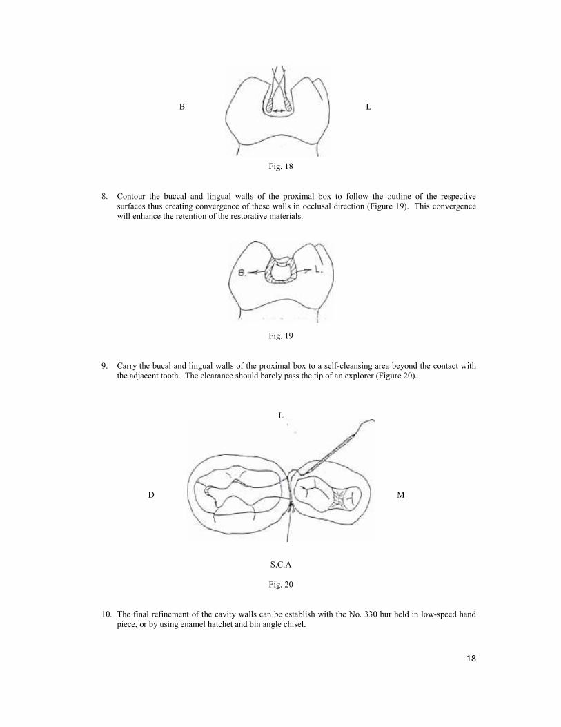
B L
Fig. 18
8. Contour the buccal and lingual walls of the proximal box to follow the outline of the respective
surfaces thus creating convergence of these walls in occlusal direction (Figure 19). This convergence
will enhance the retention of the restorative materials.
Fig. 19
9. Carry the bucal and lingual walls of the proximal box to a self-cleansing area beyond the contact with
the adjacent tooth. The clearance should barely pass the tip of an explorer (Figure 20).
L
D M
S.C.A
Fig. 20
10. The final refinement of the cavity walls can be establish with the No. 330 bur held in low-speed hand
piece, or by using enamel hatchet and bin angle chisel.

19
Internal Outline Form:
A. The Occlusal Step:
1. Establish a depth of 1.25 mm (measured at the cavosurface margin).
2. Round the pulpal floor and the internal line angles through slightly tilting the No. 330 bur in a
buccal and lingual direction. This will establish the occlusal convergence of the buccal and lingual
walls necessary for retention.
3. Establish a sharp cavosurface angle (900) of the lateral alls using the No. 169L bur.
B. The Proximal Box:
1. The axial wall is rounded to conform to the proximal surface.
2. The axio-pulpal, bucco-gingival, and lingo-gingival line angles are rounded.
3. The gingival floor is slightly concave (Figure 21) and is perpendicular to the long axis of the tooth.
Fig. 21
4. The depth of the gingival floor is approximately 1.25 mm in a pulpal direction.
5. No bevel is needed at the gingival margin, why?

20
CLASS II – CAVITY PREPARATION TOOTH NO. 75 DO
Instrumentation:
Mirror
Explorer
Enamel Hatchet 13-14
Bin Angle Chisel 17-18
No. 330 F.G. carbide bur
No. 169L F.G. carbide bur
No. 4R F.G. carbide bur
External Outline Form:
1. The cavity preparation consists basically of a proximal box and an occlusal step that join at the isthmus
(Figure 22).
L
M D
B
Fig. 22
2. Start preparation by penetrating the occlusal surface, at the central pit, with No. 330 bur in a high-speed
hand piece (held parallel to the long axis of the tooth) with water spray.
3. Using light intermittent strokes, move the bur mesially and distally to establish the occlusal step.
Leave enough bulk of tooth surface as you extend the preparation to include the lingual groove.
Maintain the bur parallel to the long axis of the tooth as you approach the transverse ridge to avoid
undermining it.
4. Establish an isthmus width approximately one-third the width of the occlusal table, then flare the
outline slightly as you approach the distal marginal ridge.
5. Establish the proximal box by extending the occlusal outline through the distal marginal ridge. Avoid
damaging the adjacent tooth by placing a short matrix strip into the embrasure or by wedging the teeth.
6. Extend the proximal box gingivally by moving the bur buccolingually in a pendulating motion (Figure
23), while applying slight pressure, until the contact is broken (a tip of an explorer can be passed
between the teeth). Maintain the bur parallel to the long axis of the tooth throughout the cavity
preparation.
B L
Fig. 23

21
7. Contour the buccal and lingual walls of the proximal box to follow the outline of the respective
surfaces, thus creating convergence of these walls in occlusal direction (Figure 24). This convergence
will enhance the retention of the restorative materials.
B L
Fig. 24
8. Carry the buccal and lingual walls of the proximal box to a self-cleansing area beyond the contact with
the adjacent tooth. The clearance should barely pass the tip of an explorer (Figure 25.)
L
M D
S.C.A
Fig. 25
9. The final refinement of the cavity walls can be established with No. 330 bur held in low-speed hand
piece. If needed, use the enamel hatchet to refine the buccal and lingual walls of the proximal box
while the gingival seat can be refined with the bin angle chisel.
Internal Outline Form:
A. The Occlusal Step:
1. Establish a depth of 1.25 mm (measured at the cavosurface margin).
2. Round the pulpal floor and the internal line angles through slightly tilting the No. 330 bur in a
buccal and lingual direction. This will establish the occlusal convergence of the buccal and lingual
walls necessary for retention.
3. Establish a sharp cavosurface angle (900) of the lateral walls using the No. 169L bur. (Care should
be taken so that the bur does not touch the pulpal floor).

22
B. The Proximal Box:
1. The axial wall is rounded to conform to the proximal surface.
2. The axio-pulpal, bucco-gingival and lingo-gingival line angles are rounded.
3. The gingival floor is slightly concave (Figure 26) and is perpendicular to the long axis of the tooth.
B L
Fig. 26
4. The width of the gingival floor is approximately 1.25 mm in a pulpal direction.
5. No bevel is needed at the gingival margin, why?

23
FORMING AND PLACING A T-BAND MATRIX
T-Band matrixes are formed from pre-cut metal strips of brass or stainless steel in the shape of long-tailed
“T’s” (Figure 27).
Wing
Tail
Fig. 27
They have the advantage of easy placement, contouring and removal. They are most suitable for the back-to-
back restorations frequently placed in primary molars.
Instrumentation:
T-Band matrix
Wooden Wedge
No. 110 plier (Howe plier)
Crown & Bridge Scissors
Spoon Excavator
Tweezer
Forming and Placing:
1. Using the Howe plier (or a pair of tweezers) band the wings of the T-Band upward (Figure 28).
Fig. 28

24
2. Curl the long end of the band (tail) under the bent wings forming a circle (Figure 29).
Fig. 29
3. Slip the long end of the band (tail) between the bent wings and fold the wings firmly over it forming a
sliding joint. The joint should be loose enough to permit matrix adjustment.
4. Pull the free-end and adjust the matrix band to a circle slightly less than the circumference of the tooth
to be restored.
5. Place the matrix on the tooth with the joint facing buccally and the free end mesially. Seat the matrix
with finger pressure, so that it extends 0.5 to 1.0 mm past the gingival cavosurface margin (Figure 30).
½ - 1 mm
Fig. 30
6. Stabilize the sliding joint with your fingers while pulling the free end of the band with your other hand
to tighten the band around the tooth.
Fig. 31

25
7. Fold the free-end distally over the sliding joint. Trim off the free-end leaving approximately 7 mm and
press it firmly against the joint,
8. Place a wedge lingually in the interproximal area under the gingival margin and press it firmly with the
tweezer handle. This will secure the matrix against the gingival cavosurface margin preventing
gingival overhang of the restoration. The wedging will also provide slight separation that will
compensate for the matrix thickness and will ensure tight contact when the wedge is removed.
Removing the T-Band Matrix:
1. Upon completion of the restorative procedure, remove the excess amalgam from the proximal area with
an explorer.
2. Secure the matrix in place with your fingers and open the joint using the spoon excavator (Figure 32).
Fig. 32
3. Support the matrix over the restored proximal area with your fingers while slipping the matrix from
around the other contact area (Figure 33).
Fig. 33
4. Cut the band close to the restoration buccally with crown and bridge scissor. Remove the wedge and
pull the matrix out lingually while pushing three free-end slightly against the adjacent tooth to prevent
damaging the contact area or the marginal ridge of the restoration (Figure 34).
Fig. 34

26
CLASS III – CAVITY PREPARATION
Class III – lesions are those affecting proximal surfaces of anterior teeth without involving the incisal edge.
Conventional (Simple) Class III – Tooth No. 52 D
Instrumentation:
Mirror
Explorer
No. ¼ and ½ Round F.G. Carbide Bur
No. 330 F.G. Carbide Bur
Low and High Speed Hand piece
External and Internal Outline Form:
1. Penetrate the center of the lesion with No. ½ round bur (mounted in a high-speed hand piece with water
spray) oriented perpendicular to the proximal surface and establish axial depth just into dentin (1 – 1.25
mm).
2. Establish the triangular shape, while extending the walls of the cavity just beyond the extent of caries
creating a smooth and continuous curve with no sharp angles (Figure 38).
Fig. 38
3. The extension of the cavity should preserve at least 1.5 mm incisally.
Internal Outline Form:
1. Create convergence of the labial, lingual and gingival walls towards the cavosurface margins to
produce mechanical retention of the composite (Figure 39).
Fig. 39
2. Pulpal floor of the cavity should be convex following the outline of the proximal surface of the tooth.
3. Use the spoon excavator to remove any caries left (in clinical situation).

27
CLASS III – SLOT PREPARATION TOOTH NO. 61 M (LINGUAL ACCESS)
This type of preparation is used for incipient Class III lesions and the access is gained either though lingual or
labial aspect depending upon caries and accessibility.
Instrumentation:
Mirror
Explorer
Spoon Excavator
No. 330 F.G. Carbide Bur
No. ¼ R F.G. Carbide Bur
Low and High Speed Hand piece
External Outline Form:
1. Penetrate the center of the lesion with No. 330 bur (mounted in a high-speed hand piece with water
spray) oriented perpendicular to the lingual (or labial) surface and establish axial depth (1 – 1.25 mm).
2. Move the bur inciso-gingivally to establish the axial wall while creating the proximal box with incisal
and gingival walls that converge lingually (Figure 40).
Fig. 40
Internal Outline Form:
1. Establish a convex labial wall that is parallel to the external tooth surface.
2. The labial wall should be extended just to break the contact with the adjacent tooth.
3. The gingival wall should also be extended to break the contact with the adjacent tooth.
4. The depth of the axial wall from the proximal surface should be approximately 1 – 1.25 mm.
5. At least 1.5 mm of sound tooth structure should be preserved incisally.
6. Create retentive grooves along the inciso-axial and gingivo-axial line angles using No. ¼ round bur
(Figure 41) (for composite resin).
Fig. 41

28
MOFIDIED CLASS III (DOVETAIL) TOOTH NO. 51 M (LINGUAL ACCESS)
This type of preparation is used for large Class III lesions where lingual or labial dovetail is added for retention
(when using composite resin).
Instrumentation:
Mirror
Explorer
Spoon Excavator
No. 330 F.G. Carbide Bur
No. ¼ R F.G. Carbide Bur
Low and High Speed Hand piece
External Outline Form:
1. Penetrate the center of the lesion with No. 330 bur (mounted) in a high speed hand piece with water
spray oriented perpendicular to the lingual surface and establish axial depth (1 – 1.25 mm).
2. Move the bur inciso-gingivally to establish the axial wall while creating the proximal box with incisal
and gingival walls that converge lingually (Figure 42).
Fig. 42
3. Establish a lingual dovetail by extending the box distally creating a 1 mm deep pulpal floor.
4. The dovetail should be confined to the mesial half of the lingual surface. Its incisal extension should
preserve at least 1 mm of sound tooth structure (Figure 43).
5. Place a short bevel (0.5 mm) at the cavosurface margin.
minimum 1 mm
D M
Fig. 43
Internal Outline Form:
1. Establish a convex labial wall that is parallel to the external tooth surface.
2. The labial wall should be extended just to break the contact with the adjacent tooth.
3. The box should also be extended to break the contact gingivally.
4. The depth of the axial wall from the proximal surface should be approximately 1 – 1.25 mm.
5. At least 1 mm of sound tooth structure should be preserved incisally.

29
FULL CROWN PREPARATION OF INCISORS TOOTH NO. 62
There are several methods of providing full coronal coverage to primary incisors:
- Acid-etched resin crowns
- Open-face stainless steel crowns
- Veneered steel crown
These all share the same tooth preparation.
Instrumentation:
Mirror
Explorer
Spoon Excavator (in clinical situation only)
No. 330 F.G. Carbide Bur
No. 169L Carbide Bur
Flame-shaped Diamond Point
No. 4 R Carbide Bur
Slow and High Speed Hand pieces
Tooth Preparation:
1. Reduce the incisal edge 1.5 mm, using a fine tapered diamond or a No. 169L carbide bur.
2. Reduce the interproximal surfaces 0.5 – 1.0 mm. This reduction should allow a crown or a crown form
to slip over the tooth. The interproximal walls should be parallel or slightly converging lingually.
There should be a featheredge finishing line at the gum margin.
Fig. 44
3. Reduce the facial surface 0.5 – 1.0 mm and the lingual surface 0.5 mm. Create a featheredge gingival
margin (Figure 45). Round all line angles.
Fig. 45
4. Remove decay if any, with a large round bur in the slow speed hand piece.

30
CELLULOID (STRIP) CROWN FORM PREPARATION
In cases of acid-etched resin crowns, a celluloid crown from is used.
Instrumentation:
Crown and Bridge Scissors
Explorer
Celluloid Crown Kit
Crown Form Preparation:
1. Before tooth preparation, select a primary incisor celluloid crown form with a mesio-distal width
approximately equal to the tooth to be restored.
2. Trim the selected crown form by cutting away excess material gingivally with crown and bridge
scissors, and trial fit the crown form. It should fit 1 mm below the gingival crest and should be of
comparable height to adjacent teeth.
3. After the celluloid crown is adequately trimmed, punch two small holes in the incisal edge with an
explorer to act as vent for the escape of trapped air as the crown is placed with resin onto the
preparation (Figure 46).
Fig. 46

31
RESIN CROWN PLACEMENT
Instrumentation:
Composite Resin Material
Explorer
Curved Scalpel Blade
Flame Carbide-Finishing Bur
Round and Pear-Shaped Finishing Bur
Abrasive Disks
Procedure:
1. Before tooth preparation, select the shade of composite resin. Place and ligate the rubber dam.
2. Place calcium hydroxide over the deepest areas of the preparation (in a clinical situation). Carefully
etch all of the remaining enamel for 60 seconds, utilizing acid gel. Rinse and dry the tooth thoroughly,
then apply a dentin-bonding agent to the entire tooth.
3. Fill the crown form approximately two thirds with a resin material, and seat onto the tooth. Excess
material should flow from the gingival margin and the vent holes. While holding the crown in place,
remove the gingival excess with an explorer.
4. Allow the material to polymerize. If using a light-cured material be certain to direct the light from both
the facial and lingual directions.
5. Remove the celluloid form using a curved scalpel blade to cut it. Then peel the form from the tooth.
6. Remove the rubber dam and evaluate the occlusion.
7. Little finishing should be required on the facial surface. A tapered finishing bur can be used to finish
the gingival margin should any irregularities be noted with a tactile examination with an explorer. A
round or pear-shaped finishing bur may be used for final contouring of the lingual surface. Abrasive
disks are used for final polishing of the areas of the crown that require contouring.

32
STAINLESS STEEL CROWN PREPARATION TOOTH NO. 75
Instrumentation:
Mirror
Explorer
Spoon Excavator
No. 330 F.G. Carbide Bur
No. 169 F.G Carbide Bur
Flame-shaped Diamond Point
No. 4 R Carbide Bur
Low and High Speed Hand piece
Tooth Preparation:
1. Evaluation of the pre-operative occlusion. Note the dental midline and the cusp-fossa relationship
bilaterally.
2. Reduce the occlusal surface with a No. 169L tapered fissure bur or a thin tapered diamond in the high-
speed hand piece. Starting from the marginal ridge, cut to a depth of 1 mm. Using the same bur,
uniformly reduce the remaining occlusal surface by 1.0 mm maintaining the cuspal inclines of the
crown (Figure 47).
B L
Fig. 47
3. Carry out proximal reduction with the same bur. Break contact with the adjacent teeth gingival and
bucco-lingually maintaining vertical walls with only a slight convergence in an occlusal direction. The
gingival margin should have a featheredge finish line. Care must be taken not to damage adjacent teeth
(Figure 48).
M D

33
4. Round all line angles using the side of the bur (Figure 49). The occluso-buccal and occluso-lingual line
angles are rounded by holding the bur at a 30-450 angle to the occlusal surface and sweeping it in a
mesio-distal direction. Buccal and lingual reduction (Figure 50) for the Unitek stainless steel crown
preparation is generally limited to this beveling and is confined to the occlusal one third of the crown.
The buccal and lingual proximal line angles are rounded by holding the bur parallel to the tooth’s long
axis and blending the surfaces together. All of the angles of the preparation should be rounded to
remove corners but not so much as to create a round preparation.
B
L
Fig. 49
Fig. 50
Crown Selection and Seating:
1. Selection of a crown begins as a trial-and-error procedure. The goals is to place the smallest crown that
can be seated on the tooth and to establish pre-existing proximal contact.
2. Try the selected crown onto the preparation by seating the lingual first and applying pressure in a
buccal direction so that the crown slides over the buccal surface into the gingival sulcus. Friction
should be felt as the crown slips over the buccal bulge (snaps on).
3. After seating a crown, establish a preliminary occlusal relationship by comparing adjacent marginal
ridge heights.
4. Crowns are manufactured longer than necessary for the average tooth, and hence may require some
trimming. A properly trimmed crown will extend approximately 1 mm into the gingival sulcus.
Before trimming place the crown onto the preparation and lightly mark the level of the gingival crest
on the crown with a sharp instrument such as a scaler or spoon excavator. Remove the crown and trim
it 1 mm below the mark with a crown and bridge scissors or with a heatless wheel on the straight hand
piece.

34
5. Contour and crimp the crown to form a tightly fitting crown. Contouring involves bending the gingival
one third of the crown’s margins inward. This is accomplished with a pair of ball and socket plier (No.
114 plier). Final close adaptation of the crown is achieved by crimping the cervical margin 1 mm
circumferentially with a special crimping plier (No. 800-417 plier) (Figure 51).
Fig. 51
6. Smoothen the margins with a heatless stone to create smooth flowing curves and to thin the margin of
the crown slightly. Rotation of the stone should be forward and at a 45 degree angles to the edge of the
crown. With a rubber wheel, remove surface scratches, it any, using light brushing strokes.
7. Evaluate occlusion.
Problems with Stainless Steel Crowns and their Causes:
1. If the crown does not seat to the same level as the adjacent teeth.
- The occlusal reduction may be inadequate.
- The crown may be too long.
- A gingival proximal ledge may exist.
- Contact may not have been broken.
2. If an extensive area of gingival blanching occurs around the crown.
- The crown may be too long.
- The crown may be grossly over contoured.
- The crown is wide gingivally (uncrimped).

35
FORMOCRESOL PULPOTOMY
Pulpotomy can be defined as the surgical removal (amputation) of the entire pulp contents of the coronal portion
of a vital tooth followed by medicament placement over intact radicular stumps to stimulate repair, fixation or
mummification of the remaining radicular pulp.
Instrumentation:
Mirror
Explorer
Spoon Excavator
Tweezer
Plastic Instrument
No. 330 F.G. Carbide Bur
No. 4 R F.G. Carbide Bur
Low and High Speed Hand pieces
Supplies:
Sterile Cotton Pellets
Buckley Formocresol ( strength)
Zinc Oxide and Eugenol
Introduction:
The pulp chamber in primary teeth occupies most of the crown, therefore the access to the pulp chamber must
be of adequate size to insure the removal of the entire coronal pulp tissues (Figure 52).
Fig. 52
36
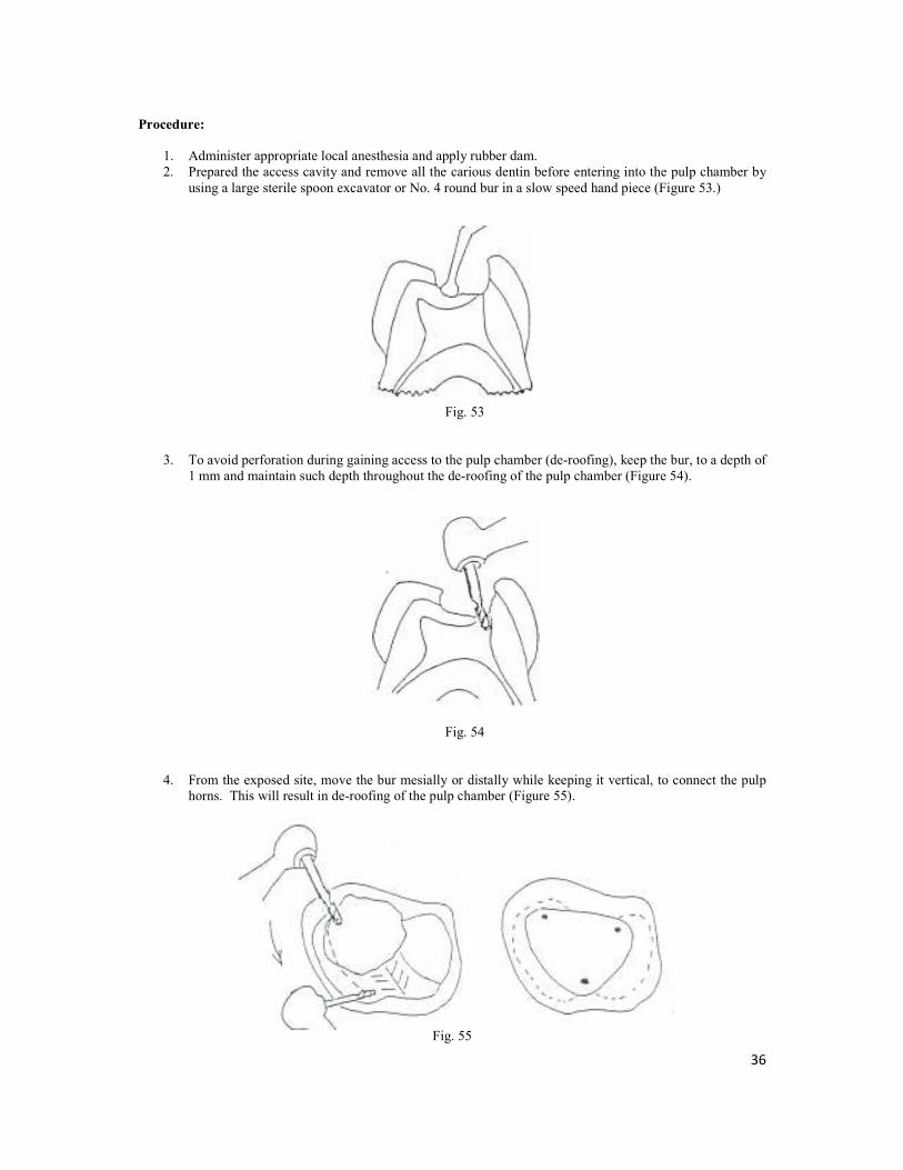
Procedure:
1. Administer appropriate local anesthesia and apply rubber dam.
2. Prepared the access cavity and remove all the carious dentin before entering into the pulp chamber by
using a large sterile spoon excavator or No. 4 round bur in a slow speed hand piece (Figure 53.)
Fig. 53
3. To avoid perforation during gaining access to the pulp chamber (de-roofing), keep the bur, to a depth of
1 mm and maintain such depth throughout the de-roofing of the pulp chamber (Figure 54).
Fig. 54
4. From the exposed site, move the bur mesially or distally while keeping it vertical, to connect the pulp
horns. This will result in de-roofing of the pulp chamber (Figure 55).
Fig. 55

37
5. Use a sterile excavator to excise the pulp tissues to the entrance of the root canals. The amputation of
the pulp tissues should be done in clean-cut strokes using a sharp spoon excavator to avoid pulling of
the remaining pulp tissues from the root canals (Figure 56).
Fig. 56
6. After complete removal of the coronal pulp tissues the hemorrhage should be minimal and hemostasis
could be achieved within 3-5 min by pressing sterile cotton pellets over the root canal orifices.
7. Following hemostatis, replace the dry pellets with others moistened with formocresol and squeeze out
excess formocresol before putting the pellets against the root canal orifices. Leave the formocresol in
place for 5 min.
8. Remove the cotton pellets, the pulp stump should appear blackish-brown. If bleeding persisted, check
for residual pulp tissues and re-apply formocresol for 2-3 min.
9. Fill the pulp chamber with a thick mixture of IRM and prepare the tooth to receive a stainless steel
crown as the pulpotomized tooth may become brittle (Figure 57).
Fig. 57

38
Problems with Pulpotomy, Causes and Solutions:
1. Failure to detect an orifice with evident bleeding.
Cause : Presence of dentin hanging over the orifice.
Solution : Stop the bleeding with cotton pellet and use a round bur to remove the
overhanging dentin above the bleeding site.
2. Bleeding does not stop following the amputation of pulp.
Cause 1 : Incomplete removal of the coronal pulp.
Solution : Irrigate with water or saline to see the tissue and excise it.
Cause 2 : Presence of inflammation in the radicular pulp.
Solution : Pulpectomy or extraction.
Cause 3 : Faulty technique resulting in perforation.
Solution : Extraction

39
APPLICATION OF TOPICAL FLUORIDE GEL
Instrumentation:
Disposable Trays of Appropriate Size (Small, Medium or Large)
Fluoride Gel
Saliva Ejector
Timekeeper
Procedure:
1. Explain the procedure and bring patient’s chair into an upright position to prevent the gel from going
down the patient’s throat.
2. Advise the patient not to swallow the F gel.
3. Choose the correct size of tray and load it with 2.5 – 5 ml of the gel.
4. Wash the teeth with water and dry with air using the air –water syringe.
5. Insert the trays in the patient’s mouth, the lower before the upper and immediately put the saliva
ejector. Tell patient to close the mouth on the trays.
6. Leave the trays in the mouth for the number of minutes indicated in the manufacturer’s instructions
(may be 4 minutes or 1 minute).
7. Never leave the patient alone in the clinic.
8. Remove the trays when the time is up.
9. Remove excess saliva and F gel in the mouth with the saliva ejector.
10. Advise the patient NOT to rinse, drink or eat for at least 30 minutes.
40
APPLICATION OF SEALANT TO OCCLUSAL PITS AND FISSURES
Instrumentation:
Sealant Material
Etching Agent (Liquid or Gel)
Application device supplied with the sealant kit by the manufacturer
Contra Angle Low Speed Hand piece
Bristle Brush or Rubber Cup
Saliva Ejector
Curing Light
Articulating Paper
Round white mounted stone (Latch type)
Procedure:
1. Isolate tooth or teeth with rubber dam in a quadrant. This is to avoid contamination by saliva.
2. Polish each tooth with bristle brush or rubber cup and water. Do not use pumice as this can block the
fissures from good etching. However, you may use the explorer to clear the fissures of debris.
3. Rinse each tooth thoroughly to remove debris and dry with air/water syringe.
4. Apply the etching liquid or gel to the occlusal pits and fissures and where applicable to the buccal pits
and lingual grooves according to the manufacturer’s instructions.
5. The etching agent is left on the tooth for the amount of time recommended by the manufacturers. This
may be 15, 30 or 60 seconds.
6. Rinse each tooth with the air-water syringe to remove all the etching material and dry with air (avoid
over drying of each tooth).
7. Look for a properly etched tooth surface which appears as dull and chalky.
8. Repeat the etching process if the enamel does not appear to be chalky.
9. Avoid saliva contamination of each tooth after the etching. If the tooth has been well isolated with the
rubber dam, then there is no problem.
Next:
10. Using the applicator in the sealant kit, apply the sealant to the etched pits and fissures.
11. Trace the fissures with an explorer to ensure that air bubbles disappear and the sealant actually
penetrates the fissures.
12. Apply the curing light for the correct exposure time as determined by the manufacturers. This may be
a duration of 15, 20 or 30 seconds.
13. Check the sealant with an explorer to be sure that the surface is smooth and hard. Check also for voids
or incomplete coverage of the occlusal pits and fissures.
14. Repeat the entire process in areas with voids or incomplete coverage.
15. After full curing of the sealant, rinse tooth surface with water and wipe the sealed surface with a moist
cotton pellet to remove any unpolymerized sealant material.
16. Check the occlusion with articulating paper. If sealant is too high, reduce it with a round stone in a
low-speed hand piece.
Related Documents