311762E Instructions - Parts List Xtreme Lowers High volume lowers for protective coatings. See page 3 for model information, see page 33 for maximum working pressure. Important Safety Instructions Read all warnings and instructions in this manual. Save these instructions. TI8630a Model L220C1 Lower without Filter Model L220C2 Lower with Built-in Filter TI8405a Patents: U.S. 6,925,926 U.S. 7,025,087 Taiwan 185733 Japan 4081437 Chinese ZL02812436.7 Other patents pending

Welcome message from author
This document is posted to help you gain knowledge. Please leave a comment to let me know what you think about it! Share it to your friends and learn new things together.
Transcript

311762E
Instructions - Parts List
Xtreme Lowers
High volume lowers for protective coatings.
See page 3 for model information, see page 33 for maximum working pressure.
Important Safety InstructionsRead all warnings and instructions in this manual. Save these instructions.
TI8630a
Model L220C1 Lower without Filter
Model L220C2 Lower with Built-in FilterTI8405a
Patents:U.S. 6,925,926U.S. 7,025,087Taiwan 185733Japan 4081437Chinese ZL02812436.7Other patents pending

Related Manuals
2 311762E
ContentsRelated Manuals . . . . . . . . . . . . . . . . . . . . 2Models . . . . . . . . . . . . . . . . . . . . . . . . . . . . 3Warnings . . . . . . . . . . . . . . . . . . . . . . . . . . 4Component Identification . . . . . . . . . . . . . 6Repair . . . . . . . . . . . . . . . . . . . . . . . . . . . . . 7
Disassembly . . . . . . . . . . . . . . . . . . . . . . 7Service Built-in Filter . . . . . . . . . . . . . . 13
Parts . . . . . . . . . . . . . . . . . . . . . . . . . . . . .14115cc, 145cc, 180cc, 250cc Lowers . . .1485cc, 220cc, 290cc Lowers . . . . . . . . .23
Kits . . . . . . . . . . . . . . . . . . . . . . . . . . . . . .30Dimensions . . . . . . . . . . . . . . . . . . . . . .31
Outlet Housing Mounting Hole Layout . .32Technical Data . . . . . . . . . . . . . . . . . . . . .33Graco Standard Warranty . . . . . . . . . . . .34Graco Information . . . . . . . . . . . . . . . . . .34
Related ManualsComponent Manuals in U.S. English:
The Xtreme Lowers manual is available in the following languages. See the following chart for specific languages and corresponding part numbers.
Manual Description
311164 Xtreme Packages Instructions and Parts
311238 NXT Air Motor Instructions and Parts
311239Air Control Modules for NXT Air Motors Instructions and Parts
Manual Language
311762 English
312451 Chinese
312452 Dutch
312453 Finnish
312454 French
312455 German
312456 Greek
312457 Italian
312458 Japanese
312459 Korean
312460 Portuguese
312461 Russian
312462 Spanish
312463 Swedish
312464 Turkish
Manual Language

Models
311762E 3
ModelsCheck the identification plate (ID) on your lower for the 6-digit part number of your lower. Use the following matrix to define the construction of your lower, based on the six digits. For example, Lower Part Number L180C1 represents the lower (L), output volume (180), carbon steel construction (C), and no filter with Xtreme Seal™ packing stack (1).
To order replacement parts, see Parts, starting on page 14.
★ Models with a 5.9 in. bolt pattern; see page 32.
For maximum fluid working pressures, see Technical Data section starting on page 33.
L 180 C 1
First Digit
Second, Third, and Fourth Digits Fifth Digit Sixth Digit
Lower Volume (cc) Material
Integrated Filter
Xtreme Seal™ Packings
Tuff Stack™ Packings
L(lower)
85★ C Carbon Steel 1 ✔
115★ 2 ✔ ✔
145 3 ✔
14A★ 4 ✔ ✔
180
18A★
220
22A★
250
290
29A★
ID TI8405a
Warnings
4 311762E
Warnings
The following warnings are for the setup, use, grounding, maintenance, and repair of this equip-ment. The exclamation point symbol alerts you to a general warning and the hazard symbol refers to procedure-specific risk. Refer back to these warnings. Additional, product-specific warnings may be found throughout the body of this manual where applicable.
WARNING
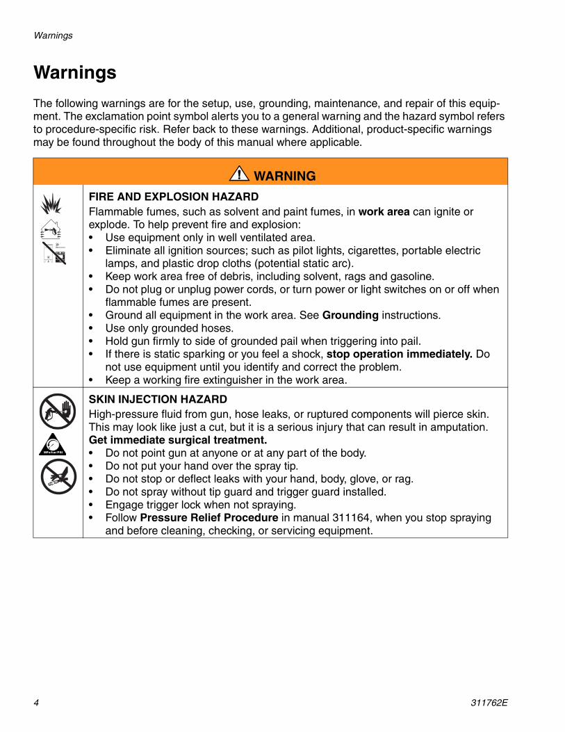
FIRE AND EXPLOSION HAZARD Flammable fumes, such as solvent and paint fumes, in work area can ignite or explode. To help prevent fire and explosion:• Use equipment only in well ventilated area.• Eliminate all ignition sources; such as pilot lights, cigarettes, portable electric
lamps, and plastic drop cloths (potential static arc). • Keep work area free of debris, including solvent, rags and gasoline.• Do not plug or unplug power cords, or turn power or light switches on or off when
flammable fumes are present.• Ground all equipment in the work area. See Grounding instructions.• Use only grounded hoses.• Hold gun firmly to side of grounded pail when triggering into pail.• If there is static sparking or you feel a shock, stop operation immediately. Do
not use equipment until you identify and correct the problem.• Keep a working fire extinguisher in the work area.
SKIN INJECTION HAZARD High-pressure fluid from gun, hose leaks, or ruptured components will pierce skin. This may look like just a cut, but it is a serious injury that can result in amputation. Get immediate surgical treatment.• Do not point gun at anyone or at any part of the body.• Do not put your hand over the spray tip.• Do not stop or deflect leaks with your hand, body, glove, or rag.• Do not spray without tip guard and trigger guard installed.• Engage trigger lock when not spraying.• Follow Pressure Relief Procedure in manual 311164, when you stop spraying
and before cleaning, checking, or servicing equipment.

Warnings
311762E 5
EQUIPMENT MISUSE HAZARD Misuse can cause death or serious injury.• Do not operate the unit when fatigued or under the influence of drugs or alcohol.• Do not exceed the maximum working pressure or temperature rating of the lowest
rated system component. See Technical Data in all equipment manuals.• Use fluids and solvents that are compatible with equipment wetted parts. See
Technical Data in all equipment manuals. Read fluid and solvent manufacturer’s warnings. For complete information about your material, request MSDS forms from distributor or retailer.
• Check equipment daily. Repair or replace worn or damaged parts immediately with genuine manufacturer’s replacement parts only.
• Do not alter or modify equipment.• Use equipment only for its intended purpose. Call your distributor for information.• Route hoses and cables away from traffic areas, sharp edges, moving parts, and
hot surfaces.• Do not kink or over bend hoses or use hoses to pull equipment.• Keep children and animals away from work area.• Comply with all applicable safety regulations.
MOVING PARTS HAZARD Moving parts can pinch or amputate fingers and other body parts.• Keep clear of moving parts.• Do not operate equipment with protective guards or covers removed.• Pressurized equipment can start without warning. Before checking, moving, or
servicing equipment, follow the Pressure Relief Procedure in manual 311164. Disconnect power or air supply.
TOXIC FLUID OR FUMES HAZARD Toxic fluids or fumes can cause serious injury or death if splashed in the eyes or on skin, inhaled, or swallowed.• Read MSDS’s to know the specific hazards of the fluids you are using.• Store hazardous fluid in approved containers, and dispose of it according to appli-
cable guidelines.• Always wear impervious gloves when spraying or cleaning equipment.
PERSONAL PROTECTIVE EQUIPMENT You must wear appropriate protective equipment when operating, servicing, or when in the operating area of the equipment to help protect you from serious injury, includ-ing eye injury, inhalation of toxic fumes, burns, and hearing loss. This equipment includes but is not limited to:• Protective eyewear • Clothing and respirator as recommended by the fluid and solvent manufacturer• Gloves• Hearing protection
WARNING
Component Identification
6 311762E
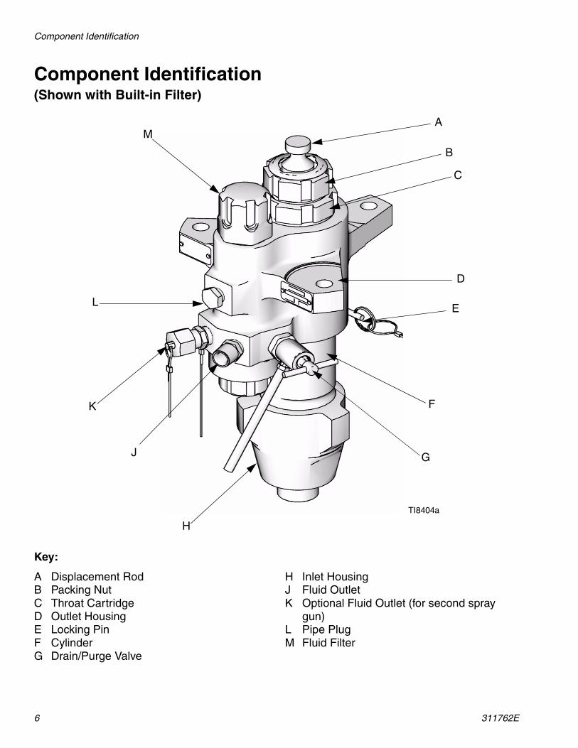
Component Identification(Shown with Built-in Filter)
Key:
A Displacement RodB Packing NutC Throat CartridgeD Outlet HousingE Locking PinF CylinderG Drain/Purge Valve
H Inlet HousingJ Fluid OutletK Optional Fluid Outlet (for second spray
gun)L Pipe PlugM Fluid Filter
A
B
C
D
E
F
G
H
J
K
L
M
TI8404a

Repair
311762E 7
Repair
Required Tools
• Set of adjustable wrenches• Torque wrench• Rubber mallet• Arbor press• Soft wooden block (approx. 1 square ft in
size)• Large vise with soft jaws• Thread lubricant• Petroleum jelly• Anti-seize lubricant 222955
DisassemblyLayout all removed parts in sequence to ease reassembly. Clean all parts with a compatible solvent and inspect them for wear or damage.
1. Relieve pressure. See your Xtreme Pack-ages manual (311164) for instructions.
2. Disconnect lower from motor as illustrated in your Xtreme Packages manual (311164). Or, if you have a cart mounted system, tip cart up to service lower on cart.
3. For lowers with built-in filters, loosen and remove both top filter cap (20) and bottom filter cap (26). See Service Built-in Filter, page 13.
4. Loosen and remove inlet housing (14) from lower cylinder (11).
5. Press inlet ball (16) out from bottom of inlet housing (14) (take care not to damage seat (18)) to remove entire inlet ball guide assembly. Remove inlet ball, bottom o-ring (27*), and seat. Then remove remaining o-rings from top and bottom grooves of inlet ball guide (15).
Repair kits are available to replace the throat (T) and piston (P) packings, and to replace the o-rings and cylinder seals. For best results, use all new parts in the kit. Kit parts are marked with an asterisk, for example (25*). These kits can also be used to convert the lower to different pack-ing materials. See the Packing Kits sec-tions.
TI8267a
20
26
TI8286a
11
14
TI8287a
}1727*
15
27*
14
16*
18

Repair
8 311762E
6. Stand lower upright in large vise. Using a rubber mallet, loosen, but do not remove packing nut (2).
7. Remove locking pin (10) from lower cylin-der (11).
8. Unscrew and lift outlet housing (8) straight up off cylinder. Be careful not to scratch displacement rod (1).
9. Remove cartridge assembly. Remove o-ring (27* or 29*) from bottom of outlet housing (8), and then unscrew packing nut (2) from packing cartridge (7). Remove female gland, male gland, and v-packings (T) from packing cartridge (7).
TI8274a
2
TI8269a
10
TI8309a
8
1
CAUTION
To reduce the possibility of costly damage to displacement rod (1) and lower cylinder (11), first place lower cylinder on a soft block of wood. Always use a rubber mallet or an arbor press to drive the displacement rod out of the lower cylinder. Never use a hammer to drive the rod out. Damage to the rod end will shorten pump life.
TI8467a
2
T
78
}27* or 29*
Female Gland
Male Gland
Repair
311762E 9
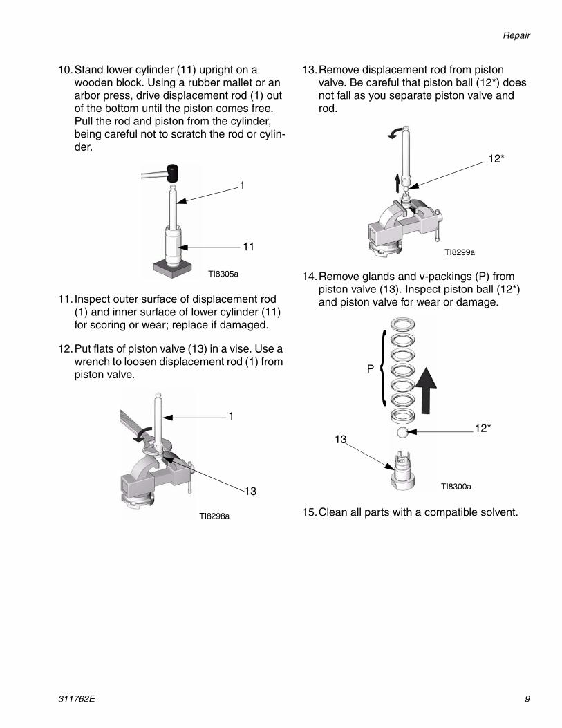
10.Stand lower cylinder (11) upright on a wooden block. Using a rubber mallet or an arbor press, drive displacement rod (1) out of the bottom until the piston comes free. Pull the rod and piston from the cylinder, being careful not to scratch the rod or cylin-der.
11. Inspect outer surface of displacement rod (1) and inner surface of lower cylinder (11) for scoring or wear; replace if damaged.
12.Put flats of piston valve (13) in a vise. Use a wrench to loosen displacement rod (1) from piston valve.
13.Remove displacement rod from piston valve. Be careful that piston ball (12*) does not fall as you separate piston valve and rod.
14.Remove glands and v-packings (P) from piston valve (13). Inspect piston ball (12*) and piston valve for wear or damage.
15.Clean all parts with a compatible solvent.
TI8305a
1
11
TI8298a
1
13
TI8299a
12*
TI8300a
13
{P
12*

Repair
10 311762E
Reassembly
1. Replace female gland on piston valve (13). Install the five v-packings (P) one at a time with lips facing up. Refer to the Packing Kits sections for the correct packing order for your lower. Install the male gland.
2. Ensure there are no burrs or debris on mat-ing threads of displacement rod (1) and pis-ton valve (13). Apply anti-seize lubricant to threads and mating surfaces of displace-ment rod and piston valve.
3. Place flats of piston valve in a vise. Place piston ball (12*) on piston valve.
4. Screw displacement rod (1) onto piston valve (13), and hand tight. Then torque to:
• 115-135 ft-lb (155-182 N•m) for 85, 115, and 145 lower sizes; or
• 190-210 ft-lb (258-285 N•m) for 220, 250, and 290 lower sizes.To convert the lower to a different packing
material, see the Packing Kits sections.
For best results, soak leather packings in oil before reassembly.
TI8461a
{P
13
Female Gland
Male Gland
Orient crowfoot of torque wrench at a 90° angle to ensure accurate torque values.
CAUTION
To reduce the possibility of costly damage to displacement rod (1) and lower cylinder (11), first place lower cylinder on a soft block of wood. Always use a rubber mallet or an arbor press to drive the displacement rod into the lower cylinder. Never use a hammer to drive the rod.
TI8462a
1
12*
13
Apply anti-seize lubricant to threads before torquing.
TI8303a
1
13

Repair
311762E 11
5. To reinstall displacement rod (1) into lower cylinder (11), first lubricate piston packings (P). Then, with piston end facing down, lower rod into cylinder. Start piston into cyl-inder as much as possible, then drive rod and piston the rest of the way into the cylin-der with an arbor press or rubber mallet.
6. Lubricate inside of packing cartridge (7), outside threads of packing nut (2), and throat packings (T). Install packing car-tridge into housing. Place male gland in packing cartridge. Install the five v-pack-ings one at a time with lips facing down. Refer to the Packing Kits sections for the correct packing order for your lower. Install female gland.Then, reassemble packing nut (2), but do not tighten.
7. Screw lower cylinder (11) onto outlet hous-ing (8) until it bottoms out. Use a wrench to tighten lower cylinder. Back off as little as possible until hole in housing lines up with flat on cylinder. Insert locking pin (10) into cylinder.
8. Install inlet seat (18), inlet ball (16), and one o-ring (27*) into inlet housing (14).
To convert lower to a different packing material, see Packing Kits sections.For best results, soak leather packings in oil before reassembly.
TI8305a
1
11 TI8467a
2
T
7
8
}
❄Blue o-ring for 220cc, 250cc, 290cc lowers.
27* or 29*❄
Female Gland
Male Gland
TI8278a
8
1011
TI8290a
27*
14
16
18

Repair
12 311762E
9. Lubricate and install o-rings (27*) in top and bottom grooves of inlet ball guide (15). Press inlet ball guide into inlet housing (14) and install shims (17).
10.Thread inlet housing (14) onto lower cylin-der (11). Torque to 140-150 ft-lb(189-203 N•m).
11.Using torque wrench, torque packing car-tridge (7) to outlet housing (8). Torque to 140-150 ft-lb (189-203 N•m).
12. Insert packings in correct orientation; see Parts, page 14. Install packing nut (2) and torque to 25-30 ft-lb (34-41 N•m).
13.For lowers with built-in filter, see Service Built-in Filter, page 13, if filter needs ser-vice. Then reinstall both top filter cap (20) and bottom filter cap (26).
14.Reconnect lower to air motor. See Xtreme Packages manual (311164).
Shims (three maximum) can be assembled either for short ball travel or long ball travel. See illustrations below for an example of each.
TI8290a
} 17*27*
15
27*
14
Shortest Ball Travel Longest Ball Travel
TI8745a TI8746a
◆ Factory set configuration for optimum pump change over.
❖ Shims can be configured to change ball travel length. Use longer ball travel length for higher viscosity fluids.
✠ Optional inlet ball spring kit available. Use to improve change over rate with longer ball travel configurations. See Kits, page 30, for more information.
◆ ❖ ✠
TI8279a
8
7
2 (Torque to 25-30 ft-lb)
(Torque to 140-150 ft-lb)
TI8281a
20
26

Repair
311762E 13
Service Built-in FilterSelect models have a built-in filter in the lower housing.
Disassembly
To remove and clean the built-in filter:
1. Use wrench to loosen and remove top filter cap (20).
2. Remove o-ring (22*), strainer (23), and fil-ter support (24).
3. Use wrench to loosen and remove bottom filter cap (26). Remove o-rings (22*, 25*).
4. Inspect o-rings (22*, 25*), strainer (23), and filter support (24). Replace if necessary.
5. Remove pipe plug (49), and use brush or drill to clean port as necessary.
Reassembly
To reassemble the built-in filter:
1. Install o-rings (22*, 25*) onto bottom filter cap (26). Then use wrench to reassemble and tighten bottom filter cap. Torque to 40-60 ft-lb (52-82 N•m).
2. Reassemble o-ring (22*) onto top filter cap (20). Install strainer (23), and filter support (24) in top filter cap. Then use wrench to install and tighten top filter cap. Torque to 40-60 ft-lb (52-82 N•m).
TI8292a
20
TI8293a
22*
2423
TI8463a
26
❄Ref. 25 is a black o-ring.
25*❄
22*
Lubricate all o-rings with petroleum jelly before installation.
TI8747a
TI8294a
26
25*❄
❄Ref. 25 is a black o-ring.
22*
TI8402a
TI8464a
20
24
22*23

Parts
14 311762E
Parts115cc, 145cc, 180cc, 250cc Lowers
TI8403a
{
{
}
14
18
16*
15
17
13
3*
12*
1
27*
11
9*
8
10
30
7
2
19*
20
21
23
24
8
10
40
41
42
26
38
49
3839
3* (Throat) See Repair Kits sections
❄ 29 is a blue o-ring for 250cc lowers only. 25 is a black o-ring.
25*❄
27*
27*
27*
27*
* Parts included in repair kits (purchase separately).See Repair Kits sections.
1
For 250cc sizes, torque to 190-210 ft-lb (258-N•m).
For 115, 145, and 180cc sizes, torque to 115-135 ft-lb (155-182 N•m).
Torque to 140-150 ft-lb (189-203 N•m).
Torque to 25-30 ft-lb (34-41 N•m).
Torque to 40-60 ft-lb (52-82 N•m).
Apply lubricant to threads before assembly.
2
4
4
49
3
1
2
1
2
3
4
(Piston) See Repair Kits sections
❄29 for 250cc lowers
22*
22*
5
5
5

Parts
311762E 15
115cc Lowers
Models L115C1, L115C2, L115C3, L115C4
▲ Replacement Danger and Warning labels, tags, and cards are available at no cost.
† For models L115C2 and L115C4 only.
* Parts included in repair kits (purchase sepa-rately). Part numbers listed are for bulk quantities. Individual quantities are included in repair kits. See 115cc Repair Kits, page 16.
Ref. Part Description Qty.1 24B820 ROD, displacement 12 15K029 NUT, packing 13* PACKINGS, stack 27 15F661 CARTRIDGE, packing 18 HOUSING, outlet
15F654 Standard; models L115C1, L115C3
1
15F659 With built-in filter; models L115C2, L115C4
1
9* 288067 O-RING, PTFE, top cylinder(pack of 10)
1
10 244826 PIN, self-locking 111 15F656 CYLINDER, lower 112* 288065 BALL, piston; 9/16 in. (14 mm)
diameter (pack of 3)1
13 24B817 VALVE, piston 114 15F667 HOUSING, inlet 115 15F664 GUIDE, ball, inlet 116* 244899 BALL, inlet; 1 in. (25 mm)
diameter (pack of 3)1
17 288064 SHIM, inlet, ball guide(pack of 9)
3
18 15F665 SEAT, 1 in. ball 119* 247393 PLUG, throat seal (pack of 10) 120† 15F859 CAP, filter, top 121† 171941 SPRING, compression 122*† 24B732 O-RING, filter; solvent resis-
tant (pack of 10)2
23† STRAINER, 60 mesh screen; see page 30 for more options
1
236496 pack of 2238446 pack of 25
24† 188420 SUPPORT, filter 125*† 24B733 O-RING, filter bottom; solvent
resistant (pack of 10)1
26† 197339 CAP, filter, bottom 127* 288068 O-RING; PTFE (pack of 10) 530▲ 172479 TAG, warning 138† 158491 FITTING, nipple 239† 244517 PLUG, packless, 0.5 in. 140† 245143 VALVE, pressure, dump 141† 116746 FITTING, barbed, plated 142† 116750 TUBE, nylon 149 PLUG, pipe
101754 Models L115C1, L115C3 1198292 Models L115C2, L115C4 1
Ref. Part Description Qty.

Parts
16 311762E
115cc Repair Kits
XtremeSeals™ Repair Kit
Kit 288058 for Models L115C1 and L115C2 Kit also includes items 9, 12, 16, 19, 22, 25, 27 (see 115cc parts list).
Tuff-Stack™ Repair Kit
Kit 288060 for Models L115C3 and L115C4 Kit also includes items 9, 12, 16, 19, 22, 25, 27 (see 115cc parts list).
Ref. Part Description Qty.3a 288074 GLAND, packing, male
(pack of 4)2
3b 288073 GLAND, packing, female (pack of 4)
2
3c 288076 V-PACKING; leather (pack of 10)
4
3d 288075 V-PACKING; Xtreme (pack of 10)
6
Throat Packings:Lips Face Down
Piston Packings:Lips Face Up
Lubricate packings; soak leather packings in oil for one hour before assembly.
3b
3c
3a
3d
3a
3c 3d
3b
Ref. Part Description Qty.3a 288074 GLAND, packing, male
(pack of 4)2
3b 288073 GLAND, packing, female (pack of 4)
2
3e 288066 V-PACKING; Tuff-Stack(pack of 10)
10
Throat Packings:Lips Face Down
Piston Packings:Lips Face Up
Lubricate Packings
}}3a
3e
3b 3a
3b
3e

Parts
311762E 17
145cc Lowers
Models L145C1, L145C2, L145C3, L145C4, L14AC1
▲ Replacement Danger and Warning labels, tags, and cards are available at no cost.
† For models L145C2 and L145C4 only.
* Parts included in repair kits (purchase sepa-rately). Part numbers listed are for bulk quantities. Individual quantities are included in repair kits. See 145cc Repair Kits, page 18.
Ref. Part Description Qty.1 24B821 ROD, displacement 12 15K030 NUT, packing 13* PACKINGS, stack 27 197325 CARTRIDGE, packing 18 HOUSING, outlet
197334 Standard; models L145C1, L145C3
1
197336 With built-in filter; models L145C2, L145C4
1
15J673 Standard; model L14AC1 19* 244892 O-RING, PTFE, top cylinder
(pack of 10)1
10 244826 PIN, self-locking 111 197315 CYLINDER, lower 112* 253029 BALL, piston; 9/16 in. (14 mm)
diameter (pack of 3)1
13 24B826 VALVE, piston 114 197303 HOUSING, inlet 115 197307 GUIDE, ball, inlet 116* 253031 BALL, inlet; 1.25 in. diameter
(pack of 3)1
17 244855 SHIM, inlet, ball guide(pack of 9)
3
18 196358 SEAT, 1 in. ball 119* 247394 PLUG, throat seal (pack of 10) 120† 197338 CAP, filter, top 121† 171941 SPRING, compression 1
22*† 24B732 O-RING, filter; solvent resis-tant (pack of 10)
2
23† STRAINER, 60 mesh screen; see page 30 for more options
1
224459 pack of 2238438 pack of 25
24† 186075 SUPPORT, filter 125*† 24B733 O-RING, filter bottom; solvent
resistant (pack of 10)1
26† 197339 CAP, filter, bottom 127* 244890 O-RING; PTFE (pack of 10) 530▲ 172479 TAG, warning 138† 158491 FITTING, nipple 239† 244517 PLUG, packless, 0.5 in. 140† 245143 VALVE, pressure, dump 141† 116746 FITTING, barbed, plated 142† 116750 TUBE, nylon 149 PLUG, pipe
101754 Models L145C1, L145C3 1198292 Models L145C2, L145C4 1
Ref. Part Description Qty.

Parts
18 311762E
145cc Repair Kits
XtremeSeals™ Repair Kit
Kit 244850 for Models L115C1, L145C2, and L14AC1
Kit also includes items 9, 12, 16, 19, 22, 25, 27 (see 145cc parts list).
Tuff-Stack™ Repair Kit
Kit 244900 for Models L145C3 and L145C4 Kit also includes items 9, 12, 16, 19, 22, 25, 27 (see 145cc parts list).
Ref. Part Description Qty.3a 244881 GLAND, packing, male
(pack of 4)2
3b 244875 GLAND, packing, female (pack of 4)
2
3c 244869 V-PACKING; leather (pack of 10)
4
3d 244863 V-PACKING; Xtreme (pack of 10)
6
Throat Packings:Lips Face Down
Piston Packings:Lips Face Up
3b
3c
3a
3d
3a
3c 3d
3b
Lubricate packings; soak leather packings in oil for one hour before assembly.
Ref. Part Description Qty.3a 244881 GLAND, packing, male
(pack of 4)2
3b 244875 GLAND, packing, female (pack of 4)
2
3e 244857 V-PACKING; Tuff-Stack(pack of 10)
10
Throat Packings:Lips Face Down
Piston Packings:Lips Face Up
Lubricate Packings
}}3a
3e
3b 3a
3b
3e

Parts
311762E 19
180cc Lowers
Models L180C1, L180C2, L180C3, L180C4, L18AC1
▲ Replacement Danger and Warning labels, tags, and cards are available at no cost.
† For models L180C2 and L180C4 only.
* Parts included in repair kits (purchase sepa-rately). Part numbers listed are for bulk quantities. Individual quantities are included in repair kits. See 180cc Repair Kits, page 20.
Ref. Part Description Qty.1 24B822 ROD, displacement 12 15K030 NUT, packing 13* PACKINGS, stack 27 197326 CARTRIDGE, packing 18 HOUSING, outlet
197334 Standard; models L180C1, L180C3
1
197336 With built-in filter; models L180C2, L180C4
1
15J673 Standard; model L18AC1 19* 244892 O-RING, PTFE, top cylinder
(pack of 10)1
10 244826 PIN, self-locking 111 197316 CYLINDER, lower 112* 253029 BALL, piston; 9/16 in. (14 mm)
diameter (pack of 3)1
13 24B827 VALVE, piston 114 197303 HOUSING, inlet 115 197307 GUIDE, ball, inlet 116* 245128 BALL, inlet; 1.25 in.diameter
(pack of 3)1
17 244855 SHIM, inlet, ball guide(pack of 9)
3
18 196358 SEAT, inlet 119* 247394 PLUG, throat seal (pack of 10) 120† 197338 CAP, filter, top 121† 171941 SPRING, compression 1
22*† 24B732 O-RING, filter; solvent resis-tant (pack of 10)
2
23† STRAINER, 60 mesh screen; see page 30 for more options
1
224459 pack of 2238438 pack of 25
24† 186075 SUPPORT, filter 125*† 24B733 O-RING, filter bottom; solvent
resistant (pack of 10)1
26† 197339 CAP, filter, bottom 127* 244890 O-RING, PTFE (pack of 10) 530▲ 172479 TAG, warning 138† 158491 FITTING, nipple 239† 244517 PLUG, packless, 0.5 in. 140† 245143 VALVE, pressure, dump 141† 116746 FITTING, barbed, plated 142† 116750 TUBE, nylon 149 PLUG, pipe
101754 Models L180C1, L180C3 1198292 Models L180C2, L180C4 1
Ref. Part Description Qty.

Parts
20 311762E
180cc Repair Kits
XtremeSeals™ Repair Kit
Kit 244851 for Models L180C1, L180C2, and L18AC1
Kit also includes items 9, 12, 16, 19, 22, 25, 27 (see 180cc parts list).
Tuff-Stack™ Repair Kit
Kit 244901 for Models L180C3 and L180C4 Kit also includes items 9, 12, 16, 19, 22, 25, 27 (see 180cc parts list).
Ref. Part Description Qty.3a 244882 GLAND, packing, male
(pack of 4)2
3b 244876 GLAND, packing, female (pack of 4)
2
3c 244870 V-PACKING; leather (pack of 10)
4
3d 244864 V-PACKING; Xtreme (pack of 10)
6
Throat Packings:Lips Face Down
Piston Packings:Lips Face Up
3b
3c
3a
3d
3a
3c 3d
3b
Lubricate packings; soak leather packings in oil for one hour before assembly.
Ref. Part Description Qty.3a 244882 GLAND, packing, male
(pack of 4)2
3b 244876 GLAND, packing, female (pack of 4)
2
3e 244858 V-PACKING; Tuff-Stack (pack of 10)
10
Throat Packings:Lips Face Down
Piston Packings:Lips Face Up
Lubricate Packings
}}3a
3e
3b 3a
3b
3e

Parts
311762E 21
250cc Lowers
Models L250C1, L250C2, L250C3, L250C4
▲ Replacement Danger and Warning labels, tags, and cards are available at no cost.
† For models L250C2 and L250C4 only.
* Parts included in repair kits (purchase sepa-rately). Part numbers listed are for bulk quantities. Individual quantities are included in repair kits. See 250cc Repair Kits, page 22.
Ref. Part Description Qty.1 24B824 ROD, displacement 12 15K031 NUT, packing 13* PACKINGS, stack 27 197328 CARTRIDGE, packing 18 HOUSING, outlet
197335 Standard; models L250C1, L250C3
1
197337 With built-in filter; models L250C2, L250C4
1
15H722 Standard, 5.9 in. bolt pattern; model L29AC1 only
1
9* 244893 O-RING, PTFE, top cylinder (pack of 10)
1
10 244826 PIN, self-locking 111 197318 CYLINDER, lower 112* 244898 BALL, piston; 7/8 in. (22 mm)
diameter (pack of 3)1
13 24B829 VALVE, piston 114 197304 HOUSING, inlet 115 197308 GUIDE, ball, inlet 116* 253030 BALL, inlet; 1.5 in.diameter
(pack of 3)1
17 244856 SHIM, inlet, ball guide(pack of 9)
3
18 197344 SEAT, inlet 119* 247395 PLUG, throat seal (pack of 10) 120† 197338 CAP, filter, top 121† 171941 SPRING, compression 122*† 24B732 O-RING, filter; solvent resis-
tant (pack of 10)2
23† STRAINER, 60 mesh screen; see page 30 for more options
1
224459 pack of 2238438 pack of 25
24† 186075 SUPPORT, filter 125*† 24B733 O-RING, filter, bottom; solvent
resistant (pack of 10)1
26† 197339 CAP, filter, bottom 127* 244894 O-RING; PTFE (pack of 10) 429 244891 O-RING, blue; PTFE
(pack of 10)1
30▲ 172479 TAG, warning 138† 158491 FITTING, nipple 239† 244517 PLUG, packless, 0.5 in. 140† 245143 VALVE, pressure, dump 141† 116746 FITTING, barbed, plated 142† 116750 TUBE, nylon 149 PLUG, pipe
101754 Models L250C1, L250C3 1198292 Models L250C2, L250C4 1
Ref. Part Description Qty.
Parts
22 311762E
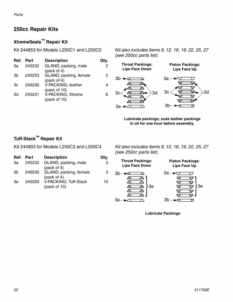
250cc Repair Kits
XtremeSeals™ Repair Kit
Kit 244853 for Models L250C1 and L250C2 Kit also includes items 9, 12, 16, 19, 22, 25, 27 (see 250cc parts list).
Tuff-Stack™ Repair Kit
Kit 244903 for Models L250C3 and L250C4 Kit also includes items 9, 12, 16, 19, 22, 25, 27 (see 250cc parts list).
Ref. Part Description Qty.3a 245232 GLAND, packing, male
(pack of 4)2
3b 245233 GLAND, packing, female (pack of 4)
2
3c 245230 V-PACKING; leather (pack of 10)
4
3d 245231 V-PACKING; Xtreme (pack of 10)
6
Throat Packings:Lips Face Down
Piston Packings:Lips Face Up
3b
3c
3a
3d
3a
3c 3d
3b
Lubricate packings; soak leather packings in oil for one hour before assembly.
Ref. Part Description Qty.3a 245232 GLAND, packing, male
(pack of 4)2
3b 246530 GLAND, packing, female (pack of 4)
2
3e 245229 V-PACKING; Tuff-Stack (pack of 10)
10
Throat Packings:Lips Face Down
Piston Packings:Lips Face Up
Lubricate Packings
}}3a
3e
3b 3a
3b
3e

Parts
311762E 23
85cc, 220cc, 290cc Lowers
TI8403a
{
{
}
14
18
16*
15
17
13
4*
12*
1
27*
11
9*
8
10
30
7
2
19*
20
21
23
24
8
10
40
41
42
26
38
49
3839
3* (Throat) See Repair Kits sections
❄ 29 is a blue o-ring. 25 is a black o-ring.
25*❄
29*❄
27*
27*
27*
* Parts included in repair kits (purchase separately).See Repair Kits sections.
1
For 220 and 290cc sizes, torque to 190-210 ft-lb (258-285 N•m).
For 85cc sizes, torque to 115-135 ft-lb (155-1N•m).
Torque to 140-150 ft-lb (189-203 N•m).
Torque to 25-30 ft-lb (34-41 N•m).
Torque to 40-60 ft-lb (52-82 N•m).
Apply lubricant to threads before assembly.
2
4
4
49
3
1
2
1
2
3
4
(Piston) See Repair Kits sections
27 for 85cc lowers
22*
22*
5
5
5

Parts
24 311762E
85cc Lowers
Models L085C1, L085C2, L085C3, L085C4
▲ Replacement Danger and Warning labels, tags, and cards are available at no cost.
† For models L085C2 and L085C4 only.
* Parts included in repair kits (purchase sepa-rately). Part numbers listed are for bulk quantities. Individual quantities are included in repair kits. See 85cc Repair Kits, page 25.
Ref. Part Description Qty.1 24B819 ROD, displacement 12 15K029 NUT, packing 13* PACKINGS, stack 14* PACKINGS, stack 17 15F660 CARTRIDGE, packing 18 HOUSING, outlet
15F654 Standard; models L085C1, L085C3
1
15F659 With built-in filter; models L085C2, L085C4
1
9* 288067 O-RING, top cylinder; PTFE (pack of 10)
1
10 244826 PIN, self-locking 111 15F682 CYLINDER, lower 112* 288065 BALL, piston; 9/16 in.
(14.3 mm) (pack of 3)1
13 24B818 VALVE, piston 114 15F667 HOUSING, inlet 115 15F664 GUIDE, ball, inlet 116* 244899 BALL, inlet; 1.0 in. (25.4 mm)
diameter (pack of 3)1
17 288064 SHIM, inlet, ball guide(pack of 9)
3
18 15F665 SEAT, inlet 119* 247393 PLUG, throat seal (pack of 10) 120† 15F859 CAP, filter, top 121† 171941 SPRING, compression 122*† 24B732 O-RING, filter; solvent resis-
tant (pack of 10)2
23† STRAINER, 60 mesh screen; see page 30 for more options
1
236496 pack of 2238446 pack of 25
24† 188420 SUPPORT, filter 125*† 24B733 O-RING, filter bottom; solvent
resistant (pack of 10)1
26† 197339 CAP, filter, bottom 127* 288068 O-RING; PTFE (pack of 10) 530▲ 172479 TAG, warning 138† 158491 FITTING, nipple 239† 244517 PLUG, packless, 0.5 in. 140† 245143 VALVE, pressure, dump 141† 116746 FITTING, barbed, plated 142† 116750 TUBE; nylon 149 PLUG, pipe
101754 Models L085C1, L085C3 1198292 Models L085C2, L085C4 1
Ref. Part Description Qty.

Parts
311762E 25
85cc Repair Kits
XtremeSeals™ Repair Kit
Kit 288054 for Models L085C1 and L085C2
Throat Packing Detail
Piston Packing Detail
Kit also includes items 9, 12, 16, 19, 22, 25, 27 (see 85cc parts list).
Tuff-Stack™ Repair Kit
Kit 288056 for Models L085C3 and L085C4
Throat Packing Detail
Piston Packing Detail
Kit also includes items 9, 12, 16, 19, 22, 25, 27 (see 85cc parts list).
Ref. Part Description Qty.3a 288070 GLAND, packing, male
(pack of 4)1
3b 288069 GLAND, packing, female (pack of 4)
1
3c 288078 V-PACKING; leather (pack of 10)
2
3d 288077 V-PACKING; Xtreme(pack of 10)
3
Ref. Part Description Qty.4a 288072 GLAND, packing, male
(pack of 4)1
4b 288071 GLAND, packing, female (pack of 4)
1
4c 288081 V-PACKING; leather (pack of 10)
2
4d 288080 V-PACKING; Xtreme (pack of 10)
3
Lubricate packings; soak leather packings in oil for one hour before assembly.
Throat Packings:Lips Face Down
Piston Packings:Lips Face Up
3b
3c
3a
3d
4a
4c 4d
4b
Ref. Part Description Qty.3a 288070 GLAND, packing, male
(pack of 4)1
3b 288069 GLAND, packing, female (pack of 4)
1
3e 288079 V-PACKING; Tuff-Stack (pack of 10)
5
Ref. Part Description Qty.4a 288072 GLAND, packing, male
(pack of 4)1
4b 288071 GLAND, packing, female (pack of 4)
1
4e 288082 V-PACKING; Tuff-Stack (pack of 10)
5
Throat Packings:Lips Face Down
Piston Packings:Lips Face Up
Lubricate Packings
}}3a
3e
3b 4a
4b
4e

Parts
26 311762E
220cc Lowers
Models L220C1, L220C2, L220C3, L220C4, L22AC1
▲ Replacement Danger and Warning labels, tags, and cards are available at no cost.
† For models L220C2 and L220C4 only.
* Parts included in repair kits (purchase sepa-rately). Part numbers listed are for bulk quantities. Individual quantities are included in repair kits. See 220cc Repair Kits, page 27.
Ref. Part Description Qty.1 24B823 ROD, displacement 12 15K031 NUT, packing 13* PACKINGS, stack 14* PACKINGS, stack 17 197327 CARTRIDGE, packing 18 HOUSING, outlet
197335 Standard; models L220C1, L220C3
1
197337 With built-in filter; models L220C2, L220C4
1
15H722 Standard, 5.9 in. bolt pattern; model L22AC1 only
1
9* 244893 O-RING, top cylinder; PTFE (pack of 10)
1
10 244826 PIN, self-locking 111 197317 CYLINDER, lower 112* 244898 BALL, piston; 7/8 in. (22 mm)
diameter (pack of 3)1
13 24B828 VALVE, piston 114 197304 HOUSING, inlet 115 197308 GUIDE, ball, inlet 116* 253030 BALL, inlet; 1.5 in. diameter
(pack of 3)1
17 244856 SHIM, inlet, ball guide(pack of 9)
3
18 197344 SEAT, inlet 119* 247395 PLUG, throat seal
(pack of 10)1
20† 197338 CAP, filter, top 121† 171941 SPRING, compression 1
22*† 24B732 O-RING, filter; solvent resis-tant (pack of 10)
2
23† STRAINER, 60 mesh screen; see page 30 for more options
1
224459 pack of 2238438 pack of 25
24† 186075 SUPPORT, filter 125*† 24B733 O-RING, filter bottom; solvent
resistant (pack of 10)1
26† 197339 CAP, filter, bottom 127* 244894 O-RING, PTFE (pack of 10) 429 244891 O-RING, blue; PTFE
(pack of 10)1
30▲ 172479 TAG, warning 138† 158491 FITTING, nipple 239† 244517 PLUG, packless, 0.5 in. 140† 245143 VALVE, pressure, dump 141† 116746 FITTING, barbed, plated 142† 116750 TUBE; nylon 149 PLUG, pipe
101754 Models L220C1, L220C3 1198292 Models L220C2, L220C4 1
Ref. Part Description Qty.

Parts
311762E 27
220cc Repair Kits
XtremeSeals™ Repair Kit
Kit 244852 for Models L220C1, L220C2, and L22AC1
Throat Packing Detail
Piston Packing Detail
Kit also includes items 9, 12, 16, 19, 22, 25, 27 (see 220cc parts list).
Tuff-Stack™ Repair Kit
Kit 244902 for Models L220C3 and L220C4
Throat Packing Detail
Piston Packing Detail
Kit also includes items 9, 12, 16, 19, 22, 25, 27 (see 220cc parts list).
Ref. Part Description Qty.3a 244883 GLAND, packing, male
(pack of 4)1
3b 244877 GLAND, packing, female (pack of 4)
1
3c 244871 V-PACKING; leather (pack of 10)
2
3d 244865 V-PACKING; Xtreme (pack of 10)
3
Ref. Part Description Qty.4a 244884 GLAND, packing, male
(pack of 4)1
4b 244878 GLAND, packing, female (pack of 4)
1
4c 244872 V-PACKING; leather (pack of 10)
2
4d 244866 V-PACKING; Xtreme (pack of 10)
3
Lubricate packings; soak leather packings in oil for one hour before assembly.
Throat Packings:Lips Face Down
Piston Packings:Lips Face Up
3b
3c
3a
3d
4a
4c 4d
4b
Ref. Part Description Qty.3a 244883 GLAND, packing, male
(pack of 4)1
3b 244877 GLAND, packing, female (pack of 4)
1
3e 244859 V-PACKING; Tuff-Stack(pack of 10)
5
Ref. Part Description Qty.4a 244884 GLAND, packing, male
(pack of 4)1
4b 244878 GLAND, packing, female (pack of 4)
1
4e 244860 V-PACKING; Tuff-Stack (pack of 10)
5
Throat Packings:Lips Face Down
Piston Packings:Lips Face Up
Lubricate Packings
}}3a
3e
3b 4a
4b
4e

Parts
28 311762E
290cc Lowers
Models L290C1, L290C2, L290C3, L290C4, L29AC1
▲ Replacement Danger and Warning labels, tags, and cards are available at no cost.
† For models L290C2 and L290C4 only.
* Parts included in repair kits (purchase sepa-rately). Part numbers listed are for bulk quantities. Individual quantities are included in repair kits. See 290cc Repair Kits, page 29.
Ref. Part Description Qty.1 24B825 ROD, displacement 12 15K031 NUT, packing 13* PACKINGS, stack 14* PACKINGS, stack 17 197327 CARTRIDGE, packing 18 HOUSING, outlet
197335 Standard, models L290C1, L290C3
1
197337 With built-in filter; models L290C2, L290C4
1
15H722 Standard, 5.9 in. bolt pattern, model L29AC1 only
9* 244893 O-RING, top cylinder; PTFE(pack of 10)
1
10 244826 PIN, self-locking 111 197319 CYLINDER, lower 112* 244899 BALL, piston; 7/8 in. (22 mm)
diameter (pack of 3)1
13 24B830 VALVE, piston 114 197304 HOUSING, inlet 115 197308 GUIDE, ball, inlet 116* 253030 BALL, inlet; 1.5 in. diameter
(pack of 3)1
17 244856 SHIM, inlet, ball guide(pack of 9)
3
18 197344 SEAT, inlet 119* 247395 PLUG, throat seal (pack of 10) 120† 197338 CAP, filter, top 121† 171941 SPRING, compression 1
22*† 24B732 O-RING, filter; solvent resis-tant (pack of 10)
2
23† STRAINER, 60 mesh screen; see page 30 for more options
1
224459 pack of 2238438 pack of 25
24† 186075 SUPPORT, filter 125*† 24B733 O-RING, filter bottom; solvent
resistant (pack of 10)1
26† 197339 CAP, filter, bottom 127* 244894 O-RING, PTFE (pack of 10) 429 244891 O-RING, blue; PTFE
(pack of 10)1
30▲ 172479 TAG, warning 138† 158491 FITTING, nipple 239† 244517 PLUG, packless, 0.5 in. 140† 245143 VALVE, pressure, dump 141† 116746 FITTING, barbed, plated 142† 116750 TUBE; nylon 149 PLUG, pipe
101754 Models L290C1, L290C3 1198292 Models L290C2, L290C4 1
Ref. Part Description Qty.

Parts
311762E 29
290cc Repair Kits
XtremeSeals™ Repair Kit
Kit 244854 for Models L290C1, L290C2, and L29AC1
Throat Packing Detail
Piston Packing Detail
Kit also includes items 9, 12, 16, 19, 22, 25, 27 (see 290cc parts list).
Tuff-Stack™ Repair Kit
Kit 244904 for Models L290C3 and L290C4
Throat Packing Detail
Piston Packing Detail
Kit also includes items 9, 12, 16, 19, 22, 25, 27 (see 290cc parts list).
Ref. Part Description Qty.3a 244885 GLAND, packing, male
(pack of 4)1
3b 244879 GLAND, packing, female (pack of 4)
1
3c 244873 V-PACKING; leather (pack of 10)
2
3d 244867 V-PACKING; Xtreme(pack of 10)
3
Ref. Part Description Qty.4a 244886 GLAND, packing, male
(pack of 4)1
4b 244880 GLAND, packing, female (pack of 4)
1
4c 244874 V-PACKING; leather (pack of 10)
2
4d 244868 V-PACKING; Xtreme(pack of 10)
3
Lubricate packings; soak leather packings in oil for one hour before assembly.
Throat Packings:Lips Face Down
Piston Packings:Lips Face Up
3b
3c
3a
3d
4a
4c 4d
4b
Ref. Part Description Qty.3a 244885 GLAND, packing, male
(pack of 4)1
3b 244879 GLAND, packing, female (pack of 4)
1
3e 244861 V-PACKING; Tuff-Stack(pack of 10)
5
Ref. Part Description Qty.4a 244886 GLAND, packing, male
(pack of 4)1
4b 244880 GLAND, packing, female (pack of 4)
1
4e 244862 V-PACKING; Tuff-Stack(pack of 10)
5
Throat Packings:Lips Face Down
Piston Packings:Lips Face Up
Lubricate Packings
}}3a
3e
3b 4a
4b
4e

Kits
30 311762E
Kits
Inlet Ball Spring Kits
Use to improve change over rates in longer ball configurations. Order kit that corresponds with your lower model.
Fluid Drain Valve Repair Kit 245145
Strainers (Ref. 23)
Kit Lower Models245190 145cc, 180cc sizes245191 220cc, 250cc, 290cc sizes
Ref. Description Qty.1 BALL, carbide 12 RING, retaining 13 O-RING, PTFE 24 SEAT, valve 15 GASKET 1
TI8406a
54
1
3
2
2 Pack 25 Pack
Lower Size 30 mesh 60 mesh 100 mesh 30 mesh 60 mesh 100 mesh
85cc
236495 236496 236497 238444 238446 238448115cc
145cc
224458 224459 224468 238436 238438 238440
180cc
220cc
250cc
290cc

Kits
311762E 31
Dimensions
Lower Dimensions
Lowers with Built-in Filters Lowers without Built-in Filters
TI8630aTI8405a
AA
Cb
BB
Ca
Lower
A(Height)in. (mm)
B(Inlet)
in. npt(m)
Ca(Outlet)in. npt(m)
Cb(Outlet)in. npt(f)
Weightlbs (kg)
Without Filter With Filter
85cc 17.0 (432) 1-1/4 2x1/2 1/2 28 (12.7) 36 (16.3)
115cc 17.0 (432) 1-1/4 2x1/2 1/2 28 (12.7) 36 (16.3)
145cc 17.0 (432) 1-1/4 2x1/2 3/4 38 (17.3) 48 (21.8)
14Acc 17.0 (432) 1-1/4 2x1/2 3/4 38 (17.3) 48 (21.8)
180cc 17.0 (432) 1-1/4 2x1/2 3/4 38 (17.3) 48 (21.8)
18Acc 17.0 (432) 1-1/4 2x1/2 3/4 38 (17.3) 48 (21.8)
220cc 17.0 (432) 1-1/4 2x1/2 1 42 (19.1) 52 (23.6)
22Acc 17.0 (432) 1-1/4 2x1/2 1 42 (19.1) 52 (23.6)
250cc 17.0 (432) 1-1/4 2x1/2 1 42 (19.1) 52 (23.6)
290cc 17.0 (432) 1-1/4 2x1/2 1 43 (19.5) 53 (24.1)
29Acc 17.0 (432) 1-1/4 2x1/2 1 43 (19.5) 53 (24.1)

Outlet Housing Mounting Hole Layout
32 311762E
Outlet Housing Mounting Hole Layout
TI8616a
TI8617a
5.9 in. (150 mm) Outlet Housing (example) Shown
8.0 in. (203 mm) Outlet Housing (example) Shown
5.9 in. (150 mm)
8.0 in. (203 mm)
Applies to 85, 115, 14A, 18A, 22A, and 29Acc Lowers
Applies to 145, 180, 220, 250, and 290cc Lowers
Technical Data
311762E 33
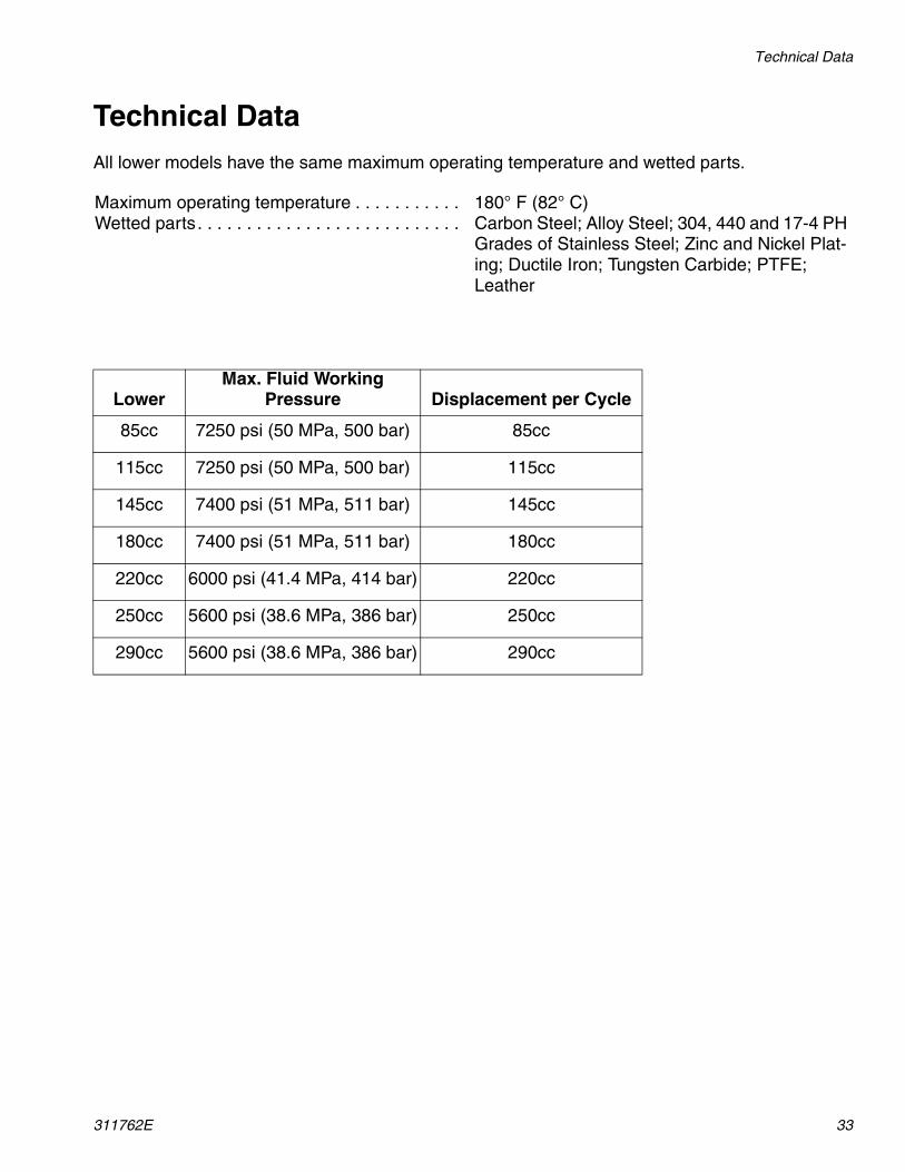
Technical DataAll lower models have the same maximum operating temperature and wetted parts.
Maximum operating temperature . . . . . . . . . . . 180° F (82° C)Wetted parts. . . . . . . . . . . . . . . . . . . . . . . . . . . Carbon Steel; Alloy Steel; 304, 440 and 17-4 PH
Grades of Stainless Steel; Zinc and Nickel Plat-ing; Ductile Iron; Tungsten Carbide; PTFE; Leather
LowerMax. Fluid Working
Pressure Displacement per Cycle
85cc 7250 psi (50 MPa, 500 bar) 85cc
115cc 7250 psi (50 MPa, 500 bar) 115cc
145cc 7400 psi (51 MPa, 511 bar) 145cc
180cc 7400 psi (51 MPa, 511 bar) 180cc
220cc 6000 psi (41.4 MPa, 414 bar) 220cc
250cc 5600 psi (38.6 MPa, 386 bar) 250cc
290cc 5600 psi (38.6 MPa, 386 bar) 290cc

All written and visual data contained in this document reflects the latest product information available at the time of publication. Graco reserves the right to make changes at any time without notice.
This manual contains English. MM 311762
Graco Headquarters: MinneapolisInternational Offices: Belgium, China, Japan, Korea
GRACO INC. P.O. BOX 1441 MINNEAPOLIS, MN 55440-1441Copyright 2006, Graco Inc. is registered to ISO 9001
www.graco.comRevised 4/2009
Graco Standard WarrantyGraco warrants all equipment referenced in this document which is manufactured by Graco and bearing its name to be free from defects in material and workmanship on the date of sale to the original purchaser for use. With the exception of any special, extended, or limited warranty published by Graco, Graco will, for a period of twelve months from the date of sale, repair or replace any part of the equipment determined by Graco to be defective. This warranty applies only when the equipment is installed, operated and maintained in accordance with Graco’s written recommendations.
This warranty does not cover, and Graco shall not be liable for general wear and tear, or any malfunction, damage or wear caused by faulty installation, misapplication, abrasion, corrosion, inadequate or improper maintenance, negligence, accident, tampering, or substitution of non-Graco component parts. Nor shall Graco be liable for malfunction, damage or wear caused by the incompatibility of Graco equipment with structures, accessories, equipment or materials not supplied by Graco, or the improper design, manufacture, installation, operation or maintenance of structures, accessories, equipment or materials not supplied by Graco.
This warranty is conditioned upon the prepaid return of the equipment claimed to be defective to an authorized Graco distributor for verification of the claimed defect. If the claimed defect is verified, Graco will repair or replace free of charge any defective parts. The equipment will be returned to the original purchaser transportation prepaid. If inspection of the equipment does not disclose any defect in material or workmanship, repairs will be made at a reasonable charge, which charges may include the costs of parts, labor, and transportation.
THIS WARRANTY IS EXCLUSIVE, AND IS IN LIEU OF ANY OTHER WARRANTIES, EXPRESS OR IMPLIED, INCLUDING BUT NOT LIMITED TO WARRANTY OF MERCHANTABILITY OR WARRANTY OF FITNESS FOR A PARTICULAR PURPOSE.
Graco’s sole obligation and buyer’s sole remedy for any breach of warranty shall be as set forth above. The buyer agrees that no other remedy (including, but not limited to, incidental or consequential damages for lost profits, lost sales, injury to person or property, or any other incidental or consequential loss) shall be available. Any action for breach of warranty must be brought within two (2) years of the date of sale.
GRACO MAKES NO WARRANTY, AND DISCLAIMS ALL IMPLIED WARRANTIES OF MERCHANTABILITY AND FITNESS FOR A PARTICULAR PURPOSE, IN CONNECTION WITH ACCESSORIES, EQUIPMENT, MATERIALS OR COMPONENTS SOLD BUT NOT MANUFACTURED BY GRACO. These items sold, but not manufactured by Graco (such as electric motors, switches, hose, etc.), are subject to the warranty, if any, of their manufacturer. Graco will provide purchaser with reasonable assistance in making any claim for breach of these warranties.
In no event will Graco be liable for indirect, incidental, special or consequential damages resulting from Graco supplying equipment hereunder, or the furnishing, performance, or use of any products or other goods sold hereto, whether due to a breach of contract, breach of warranty, the negligence of Graco, or otherwise.
FOR GRACO CANADA CUSTOMERSThe Parties acknowledge that they have required that the present document, as well as all documents, notices and legal proceedings entered into, given or instituted pursuant hereto or relating directly or indirectly hereto, be drawn up in English. Les parties reconnaissent avoir convenu que la rédaction du présente document sera en Anglais, ainsi que tous documents, avis et procédures judiciaires exécutés, donnés ou intentés, à la suite de ou en rapport, directement ou indirectement, avec les procédures concernées.
Graco Information TO PLACE AN ORDER, contact your Graco distributor or call to identify the nearest distributor.Phone: 612-623-6921 or Toll Free: 1-800-328-0211 Fax: 612-378-3505
For the latest information about Graco products, visit www.graco.com.
Related Documents