Copyright 2009 Carrier Corporation Form 30RAP-1APD The AquaSnap chiller is an effective all- in-one package that is easy to install and easy to own. AquaSnap chillers operate quietly and efficiently. Value- added features include: • Rotary scroll compression • HFC Puron ® refrigerant (R-410A) • Quiet AeroAcoustic™ fan system • Easy to use ComfortLink™ controls • Optional integrated hydronic pump package • Microchannel condenser coil technology • Accessory fluid storage tank • Optional digital scroll compressors Features/Benefits Carrier’s superior chiller design provides savings at initial purchase, at installa- tion, and for years afterward. Costs less right from the start Carrier’s AquaSnap chillers feature a compact, all-in-one package design that installs quickly and easily on the ground or the rooftop. The optional pump and hydronic components are already built in; this costs less than buy- ing and installing the components indi- vidually. The chiller’s fully integrated and pre-assembled hydronic system in- stalls in minutes. No other chiller in this class installs so easily and inexpen- sively. The preassembled and integrat- ed hydronic module utilizes top-quality components and pumps to ensure years of reliable operation. Use of the optional fluid storage tank reduces in- stallation costs and ensures sufficient fluid volume is available for close-cou- pled and process cooling applications. The AquaSnap unit’s high efficiency keeps costs down. AQUASNAP ® 30RAP010-060 Air-Cooled Chillers 10 to 60 Nominal Tons (35 to 210 Nominal kW) Advance Product Data a30-4827 a30-4826

Welcome message from author
This document is posted to help you gain knowledge. Please leave a comment to let me know what you think about it! Share it to your friends and learn new things together.
Transcript
Copyright 2009 Carrier Corporation Form 30RAP-1APD
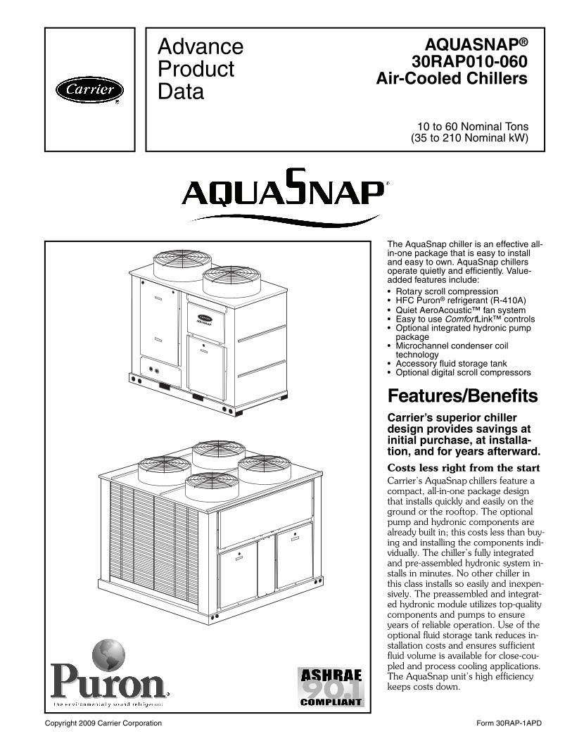
The AquaSnap chiller is an effective all-in-one package that is easy to install and easy to own. AquaSnap chillers operate quietly and efficiently. Value-added features include:• Rotary scroll compression• HFC Puron® refrigerant (R-410A)• Quiet AeroAcoustic™ fan system• Easy to use ComfortLink™ controls• Optional integrated hydronic pump
package• Microchannel condenser coil
technology• Accessory fluid storage tank• Optional digital scroll compressors
Features/BenefitsCarrier’s superior chiller design provides savings at initial purchase, at installa-tion, and for years afterward.Costs less right from the startCarrier’s AquaSnap chillers feature a compact, all-in-one package design that installs quickly and easily on the ground or the rooftop. The optional pump and hydronic components arealready built in; this costs less than buy-ing and installing the components indi-vidually. The chiller’s fully integrated and pre-assembled hydronic system in-stalls in minutes. No other chiller in this class installs so easily and inexpen-sively. The preassembled and integrat-ed hydronic module utilizes top-quality components and pumps to ensure years of reliable operation. Use of the optional fluid storage tank reduces in-stallation costs and ensures sufficient fluid volume is available for close-cou-pled and process cooling applications. The AquaSnap unit’s high efficiency keeps costs down.
AQUASNAP®
30RAP010-060Air-Cooled Chillers
10 to 60 Nominal Tons(35 to 210 Nominal kW)
AdvanceProductData
a30-4827
a30-4826

2
AquaSnap® chillers make noise in the marketplace, not the workplace.The AquaSnap chiller’s AeroAcous-tic™ fan produces up to half the sound level of propeller fans. Much of the noise reduction is in frequencies where noise is most annoying, which makes AquaSnap chillers ideal for sound-sensitive environments. When lower ambient temperatures allow part-load operation or during scheduled night-time operation, the units operate with fewer fans and become even quieter. AquaSnap chillers are quiet during the day and even quieter at night.
The savings will continue to mountBesides costing less to buy and install, AquaSnap chillers are also more af-fordable to operate. Carrier’s AquaSeries chillers are our most efficient air-cooled models. The AquaSnap chiller provides full-load EER (Energy Efficiency Ratio) up to 10.5 and IPLV (integrated part-load value) up to 15.3. AquaSnap chillers use ultra-quiet, high-efficiency rotary scroll compressors, operated in single (sizes 010 and 015) and tandem (sizes 018 to 060) per in-dependent circuit for greater efficiency at partial loads.Electronic expansion valve (EXV) allows for precise control through all operating ranges, resulting in higher efficiency and improved reliability.
Proven reliability that’s built inThousands of AquaSnap chillers arealready in service around the world. This field-proven design is backed by a12-month warranty that includes the hydronic system. The compressors are maintenance-free and protected by an auto-adaptive control that minimizes compressor wear. Unit sizes 035 and up have two independent refrigerant circuits. Year-round operation isstandard, from –20 F (–29 C) (withoptional cooler heater, low ambient control, and wind baffles) to 120 F(50 C).Rotary scroll compressors provide smooth, quiet and reliable operation.
All-in-one packageAquaSnap chillers provide the most comprehensive chilled water circuit available for any air-cooled chiller.Included is a brazed plate direct
expansion cooler that may be remote-mounted. The cooler is also completely drainable with factory-installed vents and drains.Electronic thermal-dispersion flow switch is included with the cool-er. The switch is factory installed and tested and contains no moving parts for high reliability.Optional integrated hydronics package is more than just a pump, it is an entire chilled water system,including:• Single/dual pumps up to 7.5 hp
and 120 ft head• Regular strainer• Cleanout strainer• Flow regulator• Freeze protection to –20 F (–29 C)
(with freeze protection option)• Heaters• Required piping• Pressure/temperature taps• Isolation valves for dual pump
systems• VFD compatibility
The factory-installed and tested hy-dronics package provides faster, sim-pler and less expensive installation.Digital scroll compressors are available as a factory installed option. These allow for incremental unloading with capacity modulation to better match building load when compared to standard scroll compressors.
Environmentally soundCarrier’s Puron® refrigerant (R-410A) enables you to make a responsible de-cision in the protection of the earth’s ozone layer. Puron refrigerant is an HFC refrigerant that does not contain chlorine that is damaging to the ozone layer. Puron refrigerant is unaffected by the Montreal Protocol. Puron refrig-erant is a safe, non-toxic*, efficient and environmentally sound refrigerant for the future.
Durable constructionThe 30RAP chillers have a structurally sound base that can be point-loaded, therefore, no perimeter base rail is re-quired. All 30RAP units have weather-ized cabinets constructed of heavy-duty galvanized steel with exterior panels painted with corrosion-resistant baked enamel. Inside and outside surfaces are protected to ensure long life and good appearance. The durable, galvanized steel, painted components exceed the
requirements of the 500-hour salt spray test per ASTM (American Soci-ety for Testing and Materials) B117.
ComfortLinkTM controls speak your languageThe ComfortLink controls communi-cate in plain English, making it as easy as possible to monitor and control each AquaSnap chiller while accurately maintaining fluid temperatures. The large scrolling marquee display acts as a window into the unit’s operation, providing easy-to-read information about chiller performance and over15 diagnostic functions. Carrier 30 Series chillers’ ComfortLink controls provide features such as chilled water temperature reset, demand limiting, compressor wear minimization and protection, temperature and pressure displays and diagnostic functions. These controls result in higher chiller reliability, simplified training and more productive service calls with corre-spondingly lower operational and maintenance costs.
Carrier’s exclusive accessory hand-held Navigator™ display provides con-venience and powerful information in the palm of your hand. The Navigator display helps technicians to quickly diagnose problems and even prevent them from occurring.
All AquaSnap units are ready to be used with the Carrier Comfort Network® (CCN) system.
AquaSnap units minimize the impact on your footprint, as well as your bottom lineThe integrated hydronics and the chilled fluid storage tank’s placement under the chiller minimize the foot-print, allowing easy installation almost anywhere.
Novation® heat exchanger technologyThe Novation heat exchanger design with microchannel (MCHX) condenser coil is a robust, cost effective alterna-tive to traditional coil design. These coils are offered coated or uncoated to match coil protection to site condi-tions. The Carrier Electronic Catalog (E-Cat) can be used to determine whether or not corrosion protection is recommended for particular applica-tions in coastal/marine environments. Following the input of the requested
Features/Benefits (cont)
* Under ASHRAE Standard 34-1992, R-410A isclassified as an A1 refrigerant.
3
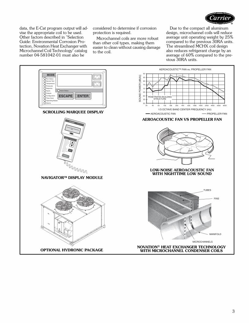
data, the E-Cat program output will ad-vise the appropriate coil to be used. Other factors described in "Selection Guide: Environmental Corrosion Pro-tection, Novation Heat Exchanger with Microchannel Coil Technology" catalog number 04-581042-01 must also be
considered to determine if corrosion protection is required. Microchannel coils are more robust than other coil types, making them easier to clean without causing damage to the coil.
Due to the compact all aluminum design, microchannel coils will reduce average unit operating weight by 25% compared to the previous 30RA units. The streamlined MCHX coil design also reduces refrigerant charge by an average of 60% compared to the pre-vious 30RA units.
Run Status
Service Test
Temperature
Pressures
Setpoints
Inputs
Outputs
Configuration
Time Clock
Operating Modes
Alarms
Alarm Status
ENTER
MODE
ESCAPE
PROPELLER FANAEROACOUSTIC FAN
1/3 OCTAVE BAND CENTER FREQUENCY (Hz)
SO
UN
D P
OW
ER
[dB
(A)]
AEROACOUSTIC™ FAN vs. PROPELLER FAN
PENETRATES BUILDINGSTRUCTURE
25 40 63 130 168 250 400 630 1080 1600 2400 4000 6300 8000
90
85
80
75
70
65
60
55
50
Run StatusService TestTemperaturesPressures
SetpointsInputs
OutputsConfigurationTime Clock
Operating ModesAlarms
ENTER
ESC
MODEAlarm Status
ComfortLink
SCROLLING MARQUEE DISPLAY
NAVIGATOR™ DISPLAY MODULE
OPTIONAL HYDRONIC PACKAGE
LOW-NOISE AEROACOUSTIC FANWITH NIGHTTIME LOW SOUND
AEROACOUSTIC FAN VS PROPELLER FAN
TUBES
FINS
MICROCHANNELS
MANIFOLD
NOVATION® HEAT EXCHANGER TECHNOLOGYWITH MICROCHANNEL CONDENSER COILS
a30-4860
4
Table of contentsPage
Features/Benefits . . . . . . . . . . . . . . . . . . . . . . . . . . . . . . . . . . . . . . . . . . .1-3Model Number Nomenclature . . . . . . . . . . . . . . . . . . . . . . . . . . . . . . . . . . . 4AHRI Capacity Ratings . . . . . . . . . . . . . . . . . . . . . . . . . . . . . . . . . . . . . . . . 5Physical Data . . . . . . . . . . . . . . . . . . . . . . . . . . . . . . . . . . . . . . . . . . . . . .6-8Options and Accessories . . . . . . . . . . . . . . . . . . . . . . . . . . . . . . . . . . . . .9,10Dimensions . . . . . . . . . . . . . . . . . . . . . . . . . . . . . . . . . . . . . . . . . . . . .11-13Selection Procedure . . . . . . . . . . . . . . . . . . . . . . . . . . . . . . . . . . . . . . . . . 14Performance Data . . . . . . . . . . . . . . . . . . . . . . . . . . . . . . . . . . . . . . . .14-17Typical Piping and Wiring . . . . . . . . . . . . . . . . . . . . . . . . . . . . . . . . . . .18-20Electrical Data . . . . . . . . . . . . . . . . . . . . . . . . . . . . . . . . . . . . . . . . . . .21-24Controls . . . . . . . . . . . . . . . . . . . . . . . . . . . . . . . . . . . . . . . . . . . . . . .25-27Typical Control Wiring Schematic . . . . . . . . . . . . . . . . . . . . . . . . . . . . . . . 28Application Data . . . . . . . . . . . . . . . . . . . . . . . . . . . . . . . . . . . . . . . . .29-34Guide Specifications . . . . . . . . . . . . . . . . . . . . . . . . . . . . . . . . . . . . . . .35-39
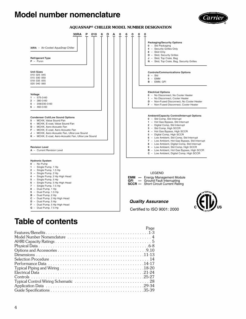
Model number nomenclature
P 0 0 030RA 0 66 D A010
30RA – Air-Cooled AquaSnap Chiller
Refrigerant TypeP – Puron
Revision LevelA – Current Revision Level
Unit Sizes010 025 045015 030 050018 035 055020 040 060
Voltage1 – 575-3-602 – 380-3-605 – 208/230-3-606 – 460-3-60
Condenser Coil/Low Sound Options5 – MCHX, Value Sound Fan6 – MCHX, E-coat, Value Sound FanD – MCHX, Aero-Acoustic FanF – MCHX, E-coat, Aero-Acoustic FanJ – MCHX, Aero-Acoustic Fan, Ultra-Low SoundK – MCHX, E-coat, Aero-Acoustic Fan, Ultra-Low Sound
Hydronic System0 – No Pump1 – Single Pump, 1 Hp2 – Single Pump, 1.5 Hp3 – Single Pump, 2 Hp4 – Single Pump, 2 Hp High Head5 – Single Pump, 5 Hp6 – Single Pump, 5 Hp High Head7 – Single Pump, 7.5 Hp8 – Dual Pump, 1 Hp9 – Dual Pump, 1.5 HpB – Dual Pump, 2 HpC – Dual Pump, 2 Hp High HeadD – Dual Pump, 5 HpF – Dual Pump, 5 Hp High HeadG – Dual Pump, 7.5 Hp
Ambient/Capacity Control/Interrupt Options0 – Std Comp, Std Interrupt1 – Hot Gas Bypass, Std Interrupt2 – Digital Comp, Std Interrupt3 – Std Comp, High SCCR4 – Hot Gas Bypass, High SCCR5 – Digital Comp, High SCCR6 – Low Ambient, Std Comp, Std Interrupt7 – Low Ambient, Hot Gas Bypass, Std Interrupt8 – Low Ambient, Digital Comp, Std Interrupt9 – Low Ambient, Std Comp, High SCCRB – Low Ambient, Hot Gas Bypass, High SCCRC – Low Ambient, Digital Comp, High SCCR
Electrical Options0 – No Disconnect, No Cooler Heater1 – No Disconnect, Cooler HeaterD – Non-Fused Disconnect, No Cooler HeaterF – Non-Fused Disconnect, Cooler Heater
Controls/Communications Options0 – Std5 – EMMB – EMM, GFI
Packaging/Security Options0 – Std Packaging4 – Security Grilles Only8 – Skid OnlyD – Skid, Security GrillesJ – Skid, Top Crate, BagN – Skid, Top Crate, Bag, Security Grilles
AQUASNAP® CHILLER MODEL NUMBER DESIGNATION
LEGENDEMM — Energy Management ModuleGFI — Ground Fault InterruptingSCCR — Short Circuit Current Rating
Quality Assurance
Certified to ISO 9001: 2000
a30-4828
5
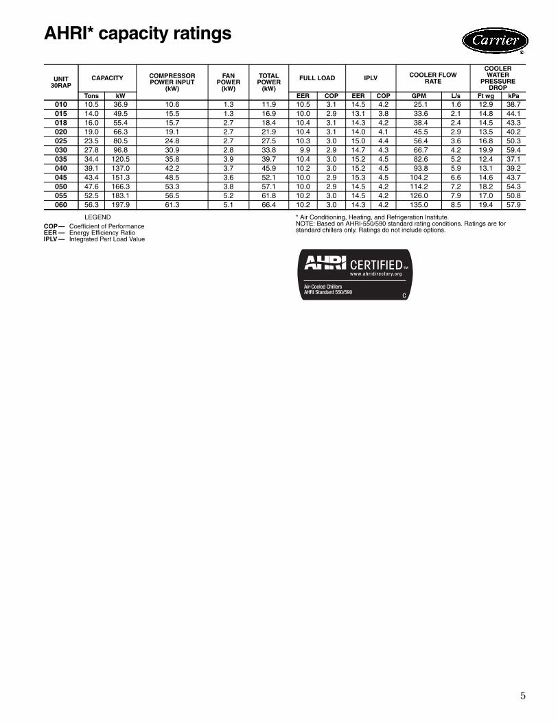
LEGEND * Air Conditioning, Heating, and Refrigeration Institute.NOTE: Based on AHRI-550/590 standard rating conditions. Ratings are forstandard chillers only. Ratings do not include options.
UNIT30RAP
CAPACITY COMPRESSORPOWER INPUT
(kW)
FAN POWER
(kW)
TOTALPOWER
(kW)
FULL LOAD IPLV COOLER FLOWRATE
COOLERWATER
PRESSUREDROP
Tons kW EER COP EER COP GPM L/s Ft wg kPa010 10.5 36.9 10.6 1.3 11.9 10.5 3.1 14.5 4.2 25.1 1.6 12.9 38.7015 14.0 49.5 15.5 1.3 16.9 10.0 2.9 13.1 3.8 33.6 2.1 14.8 44.1018 16.0 55.4 15.7 2.7 18.4 10.4 3.1 14.3 4.2 38.4 2.4 14.5 43.3020 19.0 66.3 19.1 2.7 21.9 10.4 3.1 14.0 4.1 45.5 2.9 13.5 40.2025 23.5 80.5 24.8 2.7 27.5 10.3 3.0 15.0 4.4 56.4 3.6 16.8 50.3030 27.8 96.8 30.9 2.8 33.8 9.9 2.9 14.7 4.3 66.7 4.2 19.9 59.4035 34.4 120.5 35.8 3.9 39.7 10.4 3.0 15.2 4.5 82.6 5.2 12.4 37.1040 39.1 137.0 42.2 3.7 45.9 10.2 3.0 15.2 4.5 93.8 5.9 13.1 39.2045 43.4 151.3 48.5 3.6 52.1 10.0 2.9 15.3 4.5 104.2 6.6 14.6 43.7050 47.6 166.3 53.3 3.8 57.1 10.0 2.9 14.5 4.2 114.2 7.2 18.2 54.3055 52.5 183.1 56.5 5.2 61.8 10.2 3.0 14.5 4.2 126.0 7.9 17.0 50.8060 56.3 197.9 61.3 5.1 66.4 10.2 3.0 14.3 4.2 135.0 8.5 19.4 57.9
COP— Coefficient of PerformanceEER — Energy Efficiency RatioIPLV — Integrated Part Load Value
AHRI* capacity ratings
6
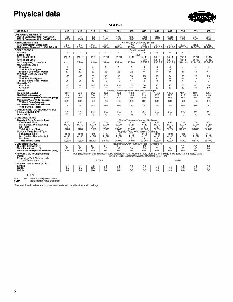
ENGLISH
LEGEND
*Flow switch and strainer are standard on all units, with or without hydronic package.
UNIT 30RAP 010 015 018 020 025 030 035 040 045 050 055 060
OPERATING WEIGHT (lb)MCHX Condenser Coil, No Pumps 704 718 1125 1133 1242 1283 2163 2185 2238 2263 2369 2375MCHX Condenser Coil, Dual Pumps 1029 1043 1450 1458 1567 1608 2850 2872 2925 2950 3056 3062
REFRIGERANT TYPE R-410A, EXV Controlled SystemTotal Refrigerant Charge (lb) 8.6 9.6 14.6 15.2 16.7 17.6 29.2 29.9 33.5 33.7 34.3 34.5Refrigerant Charge (lb) Ckt A/Ckt B 8.6/— 9.6/— 14.6/— 15.2/— 16.7/— 17.6/— 14.3/14.9 14.9/15.0 16.5/17.0 16.7/17.0 16.9/17.4 17.1/17.4
COMPRESSORS Scroll, HermeticQuantity 1 1 2 2 2 2 4 4 4 4 4 4Speed (Rpm) 3500(Qty, Tons) Ckt A (1) 11 (1) 15 (2) 9 (2) 10 (2) 13 (2) 15 (2) 10 (2) 10 (2) 11 (2) 13 (2) 13 (2) 15(Qty, Tons) Ckt B — — — — — — (2) 9 (2) 11 (2) 13 (2) 13 (2) 15 (2) 15Oil Charge (Pt) Ckt A/Ckt B 6.9/— 6.9/— 13.8/— 13.8/— 13.8/— 13.8/— 13.8/13.8 13.8/13.8 13.8/13.8 13.8/13.8 13.8/13.8 13.8/13.8No. Capacity Steps
Standard 1 1 2 2 2 2 4 4 4 4 4 4With Hot Gas Bypass — — 3 3 3 3 5 5 5 5 5 5
Digital Compressor Option 13 13 22 22 22 22 44 44 44 44 44 44Minimum Capacity Step (%)
Standard 100 100 50 50 50 50 23 23 24 25 23 25With Hot Gas Bypass — — 20 24 29 32 10 12 14 14 15 16
Digital Compressor Option 20 20 15 15 15 15 8 8 8 8 8 8 Capacity (%) Circuit A 100 100 100 100 100 100 54 47 47 50 46 50 Circuit B — — — — — — 46 53 53 50 54 50COOLER Brazed, Direct-Expansion Plate Heat Exchanger
Weight (lb) (empty) 22.4 27.5 31.8 40.3 46.3 80.6 99.4 117.9 125.3 137.5 160.4 160.4Net Fluid Volume (gal) 4.9 6.4 7.6 10.1 11.7 16.5 21.8 27.5 29.3 34.3 41.8 41.8Maximum Refrigerant Pressure (psig) 505 505 505 505 505 565 565 565 565 565 565 565Maximum Water-Side Pressure
Without Pump(s) (psig) 300 300 300 300 300 300 300 300 300 300 300 300
Maximum Water-Side PressureWith Pump(s) (psig) 150 150 150 150 150 150 150 150 150 150 150 150
COOLER WATER CONNECTIONS (in.)Inlet and Outlet, FPT 1 1/2 1 1/2 1 1/2 1 1/2 1 1/2 2 21/2 21/2 21/2 21/2 21/2 21/2Drain (NPT) 1/2 1/2 1/2 1/2 1/2 1/2 1/2 1/2 1/2 1/2 1/2 1/2
CONDENSER FANSStandard Aero-Acoustic Type Plastic Type, Axial, Vertical Discharge
Fan Speed (Rpm) 850 850 850 850 850 850 850 850 850 850 850 850No. Blades...Diameter (in.) 9...30 9...30 9...30 9...30 9...30 9...30 9...30 9...30 9...30 9...30 9...30 9...30No. Fans 1 1 2 2 2 2 3 3 3 3 4 4Total Airflow (Cfm) 9400 9400 17,500 17,500 19,400 19,400 29,600 29,500 29,300 30,500 38,800 38,800
Optional Value Sound Type Propeller Type, Axial, Vertical DischargeFan Speed (Rpm) 1140 1140 1140 1140 1140 1140 1140 1140 1140 1140 1140 1140No. Blades...Diameter (in.) 4...30 4...30 4...30 4...30 4...30 4...30 4...30 4...30 4...30 4...30 4...30 4...30No. Fans 1 1 2 2 2 2 3 3 3 3 4 4Total Airflow (Cfm) 12,600 12,600 23,400 23,400 26,000 26,000 39,800 39,600 39,300 41,000 52,100 52,100
CONDENSER COILS Novation® MCHX Aluminum Tube, Aluminum FinQuantity (Ckt A/Ckt B) 1/— 1/— 1/— 1/— 1/— 1/— 1/1 1/1 1/1 1/1 1/1 1/1Total Face Area (sq ft) 17 17 26 26 33 33 53 53 66 66 66 66
Maximum Refrigerant Pressure (psig) 656 656 656 656 656 656 656 656 656 656 656 656HYDRONIC MODULE (Optional)* Pump(s), Strainer with Blowdown Valve, Expansion Tank, Pressure Taps, Drain and Vent Plugs, Flow Switch, and Balance Valve
Pump Single or Dual, Centrifugal Monocell Pump(s), 3500 RpmExpansion Tank Volume (gal)
Total/Acceptance 5.0/2.9 10.0/5.5CHASSIS DIMENSIONS (ft - in.)
Length 5-7 5-7 7-5 7-5 7-5 7-5 7-5 7-5 7-5 7-5 7-5 7-5Width 3-5 3-5 3-5 3-5 3-5 3-5 7-9 7-9 7-9 7-9 7-9 7-9
Height 5-6 5-6 5-6 5-6 6-6 6-6 6-6 6-6 6-6 6-6 6-6 6-6
EXV — Electronic Expansion ValveMCHX — Microchannel Heat Exchanger
Physical data

7
SI
LEGEND
*Flow switch and strainer are standard on all units, with or without hydronic package.
UNIT 30RAP 010 015 018 020 025 030 035 040 045 050 055 060
OPERATING WEIGHT (kg)MCHX Condenser Coil, No Pump 319 326 510 514 564 582 981 991 1015 1026 1075 1077MCHX Condenser Coil, Dual Pump 467 473 658 661 711 729 1293 1303 1327 1338 1386 1389
REFRIGERANT TYPE R-410A, EXV Controlled SystemTotal Refrigerant Charge (kg) 3.9 4.4 6.6 7.1 7.6 8.0 13.4 13.6 15.6 15.7 16.0 16.1Refrigerant Charge (kg) Ckt A/Ckt B 3.9/— 4.4/— 6.6/— 7.1/— 7.6/— 8.0/— 6.8/6.7 6.8/6.8 7.8/7.8 7.8/7.8 7.9/8.1 8.1/8.1
COMPRESSORS Scroll, HermeticQuantity 1 1 2 2 2 2 4 4 4 4 4 4Speed (R/s) 58.3(Qty, kW) Ckt A (1) 38 (1) 53 (2) 32 (2) 35 (2) 46 (2) 53 (2) 35 (2) 35 (2) 38 (2) 46 (2) 46 (2) 53(Qty, kW) Ckt B — — — — — — (2) 32 (2) 38 (2) 46 (2) 46 (2) 53 (2) 53Oil Charge (L) Ckt A/Ckt B 3.3/— 3.3/— 6.5/— 6.5/— 6.5/— 6.5/— 6.5/6.5 6.5/6.5 6.5/6.5 6.5/6.5 6.5/6.5 6.5/6.5No. Capacity Steps
Standard 1 1 2 2 2 2 4 4 4 4 4 4With Hot Gas Bypass — — 3 3 3 3 5 5 5 5 5 5
Digital Compressor Option 13 13 22 22 22 22 44 44 44 44 44 44Minimum Capacity Step (%)
Standard 100 100 50 50 50 50 23 23 24 25 23 25With Hot Gas Bypass — — 20 24 29 32 10 12 14 14 15 16
Digital Compressor Option 20 20 15 15 15 15 8 8 8 8 8 8 Capacity (%) Circuit A 100 100 100 100 100 100 54 47 47 50 46 50 Circuit B — — — — — — 46 53 53 50 54 50COOLER Brazed, Direct-Expansion Plate Heat Exchanger
Weight (kg) (empty) 10.1 12.5 14.4 18.3 21.0 36.6 45.1 53.5 56.8 62.4 72.8 72.8Net Fluid Volume (L) 18.4 24.1 28.8 38.0 44.4 62.4 82.7 104.0 111.1 130.0 158.3 158.3Maximum Refrigerant Pressure (kPa) 3482 3482 3482 3482 3482 3896 3896 3896 3896 3896 3896 3896Maximum Water-Side Pressure
Without Pump(s) (kPa) 2068 2068 2068 2068 2068 2068 2068 2068 2068 2068 2068 2068
Maximum Water-Side PressureWith Pump(s) (kPa) 1034 1034 1034 1034 1034 1034 1034 1034 1034 1034 1034 1034
COOLER WATER CONNECTIONS (in.)Inlet and Outlet, FPT 1 1/2 1 1/2 1 1/2 1 1/2 1 1/2 2 21/2 21/2 21/2 21/2 21/2 21/2Drain (NPT) 1/2 1/2 1/2 1/2 1/2 1/2 1/2 1/2 1/2 1/2 1/2 1/2
CONDENSER FANSStandard Aero-Acoustic Type Plastic Type, Axial, Vertical Discharge
Fan Speed (R/s) 14.2 14.2 14.2 14.2 14.2 14.2 14.2 14.2 14.2 14.2 14.2 14.2No. Blades...Diameter (mm) 9...762 9...762 9...762 9...762 9...762 9...762 9...762 9...762 9...762 9...762 9...762 9...762No. Fans 1 1 2 2 2 2 3 3 3 3 4 4Total Airflow (L/s) 4400 4400 8300 8300 9200 9200 14,000 14,000 13,800 14,400 18,300 18,300
Optional Value Sound Type Propeller Type, Axial, Vertical DischargeFan Speed (R/s) 19.0 19.0 19.0 19.0 19.0 19.0 19.0 19.0 19.0 19.0 19.0 19.0No. Blades...Diameter (mm) 4...762 4...762 4...762 4...762 4...762 4...762 4...762 4...762 4...762 4...762 4...762 4...762No. Fans 1 1 2 2 2 2 3 3 3 3 4 4Total Airflow (L/s) 5900 5900 11,000 11,000 12,300 12,300 18,800 18,700 18,500 19,400 24,600 24,600
CONDENSER COILS Novation® MCHX Aluminum Tube, Aluminum FinQuantity (Ckt A/Ckt B) 1/— 1/— 1/— 1/— 1/— 1/— 1/1 1/1 1/1 1/1 1/1 1/1Total Face Area (sq m) 1.6 1.6 2.4 2.4 3.1 3.1 4.9 4.9 6.1 6.1 6.1 6.1
Maximum Refrigerant Pressure (kPa) 4523 4523 4523 4523 4523 4523 4523 4523 4523 4523 4523 4523HYDRONIC MODULE (Optional)* Pump(s), Strainer with Blowdown Valve, Expansion Tank, Pressure Taps, Drain and Vent Plugs, Flow Switch, and Balance Valve
Pump Single or Dual, Centrifugal Monocell Pump(s), 3500 RpmExpansion Tank Volume (L)
Total/Acceptance 18.9/11.0 37.9/20.8CHASSIS DIMENSIONS (mm)
Length 1702 1702 2261 2261 2261 2261 2261 2261 2261 2261 2261 2261Width 1041 1041 1041 1041 1041 1041 2362 2362 2362 2362 2362 2362
Height 1676 1676 1676 1676 1981 1981 1981 1981 1981 1981 1981 1981
EXV — Electronic Expansion ValveMCHX — Microchannel Heat Exchanger
8
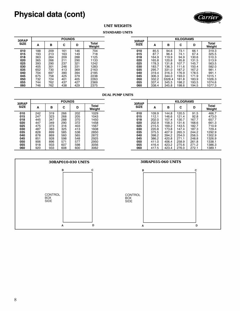
UNIT WEIGHTS
STANDARD UNITS
DUAL PUMP UNITS
30RAPSIZE
POUNDS30RAPSIZE
KILOGRAMS
A B C D TotalWeight A B C D Total
Weight010 188 209 161 146 704 010 85.5 94.6 73.1 66.1 319.3015 193 213 163 149 718 015 87.7 96.4 74.1 67.4 325.5018 363 264 209 288 1125 018 164.9 119.9 94.9 130.6 510.3020 365 266 211 290 1133 020 165.8 120.8 95.8 131.5 513.9025 393 290 237 321 1242 025 178.3 131.8 107.7 145.7 563.5030 405 301 246 331 1283 030 183.7 136.3 111.6 150.4 582.0035 652 730 413 369 2163 035 295.7 331.0 187.2 167.2 981.1040 704 697 390 394 2185 040 319.4 316.3 176.9 178.5 991.1045 675 758 425 379 2238 045 306.3 344.0 193.0 171.9 1015.1050 732 724 401 405 2263 050 332.2 3328.4 181.8 183.9 1026.3055 744 762 437 427 2369 055 337.4 345.5 198.2 193.5 1074.6060 746 762 438 429 2375 060 338.4 345.8 198.6 194.5 1077.3
30RAPSIZE
POUNDS30RAPSIZE
KILOGRAMS
A B C D TotalWeight A B C D Total
Weight010 242 319 266 202 1029 010 109.9 144.8 120.5 91.5 466.7015 247 323 268 205 1043 015 112.1 146.6 121.4 92.8 473.0018 445 347 288 370 1450 018 202.0 157.4 130.7 167.7 657.7020 447 349 290 372 1458 020 202.9 158.3 131.6 168.6 661.3025 475 373 316 403 1567 025 215.5 169.2 143.5 182.7 710.9030 487 383 325 413 1608 030 220.8 173.8 147.4 187.3 729.4035 828 899 585 538 2850 035 375.5 407.9 265.3 244.2 1292.9040 878 869 560 565 2872 040 398.2 394.2 254.0 256.5 1302.9045 851 928 598 548 2925 045 386.2 420.8 271.1 248.8 1326.9050 906 896 571 577 2950 050 411.0 406.4 258.9 261.8 1338.1055 918 933 607 598 3056 055 416.4 423.2 275.6 271.2 1386.3060 920 933 608 600 3062 060 417.5 423.4 276.0 272.1 1389.1
B
A
C
D
CONTROLBOXSIDE
B
A
C
D
CONTROLBOXSIDE
30RAP010-030 UNITS 30RAP035-060 UNITS
a30-4861
Physical data (cont)
Administrador
Rectángulo
9
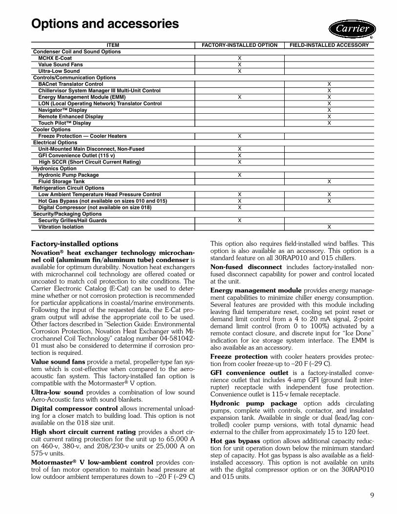
Factory-installed optionsNovation® heat exchanger technology microchan-nel coil (aluminum fin/aluminum tube) condenser isavailable for optimum durability. Novation heat exchangerswith microchannel coil technology are offered coated oruncoated to match coil protection to site conditions. TheCarrier Electronic Catalog (E-Cat) can be used to deter-mine whether or not corrosion protection is recommendedfor particular applications in coastal/marine environments.Following the input of the requested data, the E-Cat pro-gram output will advise the appropriate coil to be used.Other factors described in "Selection Guide: EnvironmentalCorrosion Protection, Novation Heat Exchanger with Mi-crochannel Coil Technology" catalog number 04-581042-01 must also be considered to determine if corrosion pro-tection is required.Value sound fans provide a metal, propeller-type fan sys-tem which is cost-effective when compared to the aero-acoustic fan system. This factory-installed fan option iscompatible with the Motormaster® V option.Ultra-low sound provides a combination of low soundAero-Acoustic fans with sound blankets.Digital compressor control allows incremental unload-ing for a closer match to building load. This option is notavailable on the 018 size unit.High short circuit current rating provides a short cir-cuit current rating protection for the unit up to 65,000 Aon 460-v, 380-v, and 208/230-v units or 25,000 A on575-v units. Motormaster® V low-ambient control provides con-trol of fan motor operation to maintain head pressure atlow outdoor ambient temperatures down to –20 F (–29 C)
This option also requires field-installed wind baffles. Thisoption is also available as an accessory. This option is astandard feature on all 30RAP010 and 015 chillers.Non-fused disconnect includes factory-installed non-fused disconnect capability for power and control locatedat the unit.Energy management module provides energy manage-ment capabilities to minimize chiller energy consumption.Several features are provided with this module includingleaving fluid temperature reset, cooling set point reset ordemand limit control from a 4 to 20 mA signal, 2-pointdemand limit control (from 0 to 100%) activated by aremote contact closure, and discrete input for “Ice Done”indication for ice storage system interface. The EMM isalso available as an accessory.Freeze protection with cooler heaters provides protec-tion from cooler freeze-up to –20 F (–29 C).GFI convenience outlet is a factory-installed conve-nience outlet that includes 4-amp GFI (ground fault inter-rupter) receptacle with independent fuse protection.Convenience outlet is 115-v female receptacle.Hydronic pump package option adds circulatingpumps, complete with controls, contactor, and insulatedexpansion tank. Available in single or dual (lead/lag con-trolled) cooler pump versions, with total dynamic headexternal to the chiller from approximately 15 to 120 feet.Hot gas bypass option allows additional capacity reduc-tion for unit operation down below the minimum standardstep of capacity. Hot gas bypass is also available as a field-installed accessory. This option is not available on unitswith the digital compressor option or on the 30RAP010and 015 units.
ITEM FACTORY-INSTALLED OPTION FIELD-INSTALLED ACCESSORYCondenser Coil and Sound Options
MCHX E-Coat XValue Sound Fans XUltra-Low Sound X
Controls/Communication OptionsBACnet Translator Control XChillervisor System Manager III Multi-Unit Control XEnergy Management Module (EMM) X XLON (Local Operating Network) Translator Control XNavigator™ Display XRemote Enhanced Display XTouch Pilot™ Display X
Cooler OptionsFreeze Protection — Cooler Heaters X
Electrical OptionsUnit-Mounted Main Disconnect, Non-Fused XGFI Convenience Outlet (115 v) X
High SCCR (Short Circuit Current Rating) XHydronics Option
Hydronic Pump Package XFluid Storage Tank X
Refrigeration Circuit OptionsLow Ambient Temperature Head Pressure Control X XHot Gas Bypass (not available on sizes 010 and 015) X XDigital Compressor (not available on size 018) X
Security/Packaging OptionsSecurity Grilles/Hail Guards XVibration Isolation X
Options and accessories
10
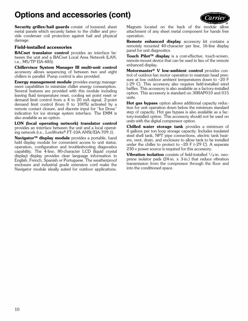
Security grilles/hail guards consist of louvered, sheetmetal panels which securely fasten to the chiller and pro-vide condenser coil protection against hail and physicaldamage.
Field-installed accessoriesBACnet translator control provides an interface be-tween the unit and a BACnet Local Area Network (LAN,i.e., MS/TP EIA-485).Chillervisor System Manager III multi-unit controlaccessory allows sequencing of between two and eightchillers in parallel. Pump control is also provided.Energy management module provides energy manage-ment capabilities to minimize chiller energy consumption.Several features are provided with this module includingleaving fluid temperature reset, cooling set point reset ordemand limit control from a 4 to 20 mA signal, 2-pointdemand limit control (from 0 to 100%) activated by aremote contact closure, and discrete input for “Ice Done”indication for ice storage system interface. The EMM isalso available as an option.LON (local operating network) translator controlprovides an interface between the unit and a local operat-ing network (i.e., LonWorks® FT-10A ANSI/EIA-709.1).Navigator™ display module provides a portable, handheld display module for convenient access to unit status,operation, configuration and troubleshooting diagnosticscapability. The 4-line, 80-character LCD (liquid crystaldisplay) display provides clear language information inEnglish, French, Spanish or Portuguese. The weatherproofenclosure and industrial grade extension cord make theNavigator module ideally suited for outdoor applications.
Magnets located on the back of the module allowattachment of any sheet metal component for hands freeoperation.Remote enhanced display accessory kit contains aremotely mounted 40-character per line, 16-line displaypanel for unit diagnostics.Touch Pilot™ display is a cost-effective, touch-screen,remote-mount device that can be used in lieu of the remoteenhanced display.Motormaster® V low-ambient control provides con-trol of outdoor-fan motor operation to maintain head pres-sure at low outdoor ambient temperatures down to –20 F(–29 C). This accessory also requires field-installed windbaffles. This accessory is also available as a factory-installedoption. This accessory is standard on 30RAP010 and 015units.Hot gas bypass option allows additional capacity reduc-tion for unit operation down below the minimum standardstep of capacity. Hot gas bypass is also available as a fac-tory-installed option. This accessory should not be used onunits with the digital compressor option.Chilled water storage tank provides a minimum of4 gallons per ton loop storage capacity. Includes insulatedsteel shell tank, NPT pipe connections, electric tank heat-ers, vent, drain, and enclosure to allow tank to be installedunder the chiller to protect to –20 F (–29 C). A separate230 v power source is required for this accessory.Vibration isolation consists of field-installed 1/4-in. neo-prene isolator pads (24-in. x 3-in.) that reduce vibrationtransmission from the compressor through the floor andinto the conditioned space.
Options and accessories (cont)
11
40.5
0 [1
028.
7]
FIE
LD P
OW
ER
EN
TRY
SE
E N
OTE
#2
7/8
22.4
[]
24.8
563
1.2
[]
4.61 11
7.1
[]
SE
E N
OTE
#3
TYP
.
1.00
25.4
[]
SE
E N
OTE
#3
TYP
.
1.00
25.4
[]
9.68
245.
9[
]
15.4
339
1.9
[]
9.52 24
1.8
[]
48 [1
219]
MIN
.
36 [9
14] M
IN.
72 [1
829]
MIN
.
36 [9
14] M
IN.
66.5
0 [1
689.
1]
RA
DIU
S20
[508
]C
ON
TRO
L B
OX
HIN
GE
D A
CC
ES
S
1.50
38.1
[]
1.50
38.1
[]Y
X
HS
EE
NO
TE #
5
UN
ITC
EN
TER
OF
GR
AV
ITY
UN
IT H
EIG
HT
VIC
TAU
LIC
CO
NN
EC
TIO
NS
XY
H (S
TAN
DA
RD
)H
(VA
LUE
SO
UN
D)
WA
TER
IN/O
UT
30R
AP
010
18.4
0 [4
67]
37.8
0 [9
60]
66.5
[168
9]61
.0 [1
549]
2"30
RA
P01
518
.35
[466
]37
.69
[957
]66
.5 [1
689]
61.0
[154
9]2"
RIG
HT
SID
EV
IEW
CO
NTR
OL
BO
XH
ING
ED
AC
CE
SS
NO
TES
:
1. D
O N
OT
CA
P O
R O
THE
RW
ISE
OB
STR
UC
T TH
E
LIQ
UID
LIN
E T
EM
PE
RA
TUR
E R
ELI
EF.
2.
7/8
[22.
4] P
ILO
T H
OLE
PR
OV
IDE
D F
OR
LO
CA
TIN
G F
IELD
PO
WE
R W
IRIN
G.
A
CTU
AL
HO
LE R
EQ
UIR
ED
DE
PE
ND
S O
N F
IELD
WIR
E S
IZIN
G.
3.
0.43
7 [1
1.10
] HO
LE U
SE
D F
OR
MO
UN
TIN
G U
NIT
.
4. U
NIT
MU
ST
HA
VE
CLE
AR
AN
CE
S A
S F
OLL
OW
S:
T
OP
- D
O N
OT
RE
STR
ICT.
C
OIL
SID
E -
72 [1
829]
FR
OM
SO
LID
SU
RFA
CE
.
PA
NE
L S
IDE
- 48
[121
9] P
ER
NE
C.
5. S
EE
TA
BLE
CO
LUM
N H
; DIM
EN
SIO
N F
OR
STA
ND
AR
D F
AN
OR
VA
LUE
S
OU
ND
FA
N O
PTI
ON
.
6. C
AR
RIE
R D
OE
S N
OT
RE
CO
MM
EN
D IN
STA
LLA
TIO
N IN
A P
IT.
7. U
NIT
CA
N B
E H
AN
DLE
D U
SIN
G T
HE
FO
RK
TR
UC
K L
IFT
PO
CK
ETS
.
8. W
ATE
R C
ON
NE
CTI
ON
S R
EC
ES
SE
D 2
-3/8
INC
HE
S IN
SID
E U
NIT
.
9. D
IME
NS
ION
S A
RE
IN IN
CH
ES
. DIM
EN
SIO
NS
IN [
] A
RE
IN M
ILLI
ME
TER
S
CO
MP
RE
SS
OR
AC
CE
SS
CO
ILA
RE
A
AIR
FLO
W
AIR
FLO
W
FRO
NT
VIE
W
PA
NE
L S
IDE
SE
E N
OTE
#4
CO
IL S
IDE
SE
E N
OTE
#4
SE
RV
ICE
AC
CE
SS
SE
RV
ICE
CLE
AR
AN
CE
BO
RD
ER
(NO
T TO
SC
ALE
)
TOP
VIE
W
CG
VA
LUE
SO
UN
D F
AN
OP
TIO
N(P
ICTO
RIA
LLY
)
FIE
LD C
ON
TRO
LW
IRIN
G C
ON
NE
CTI
ON
S
WA
TER
-IN
WA
TER
-OU
T
FOR
KTR
UC
KP
OC
KE
TS
a30-4562
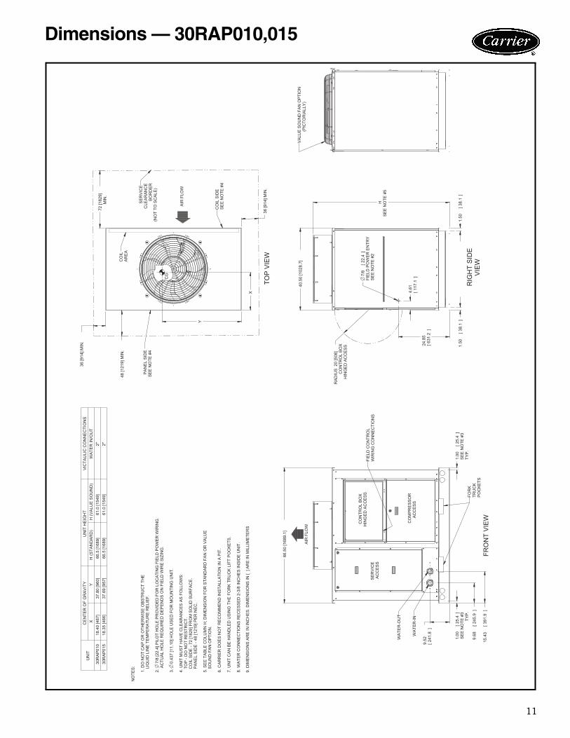
Dimensions — 30RAP010,015

12
RA
DIU
S20
[508
]C
ON
TRO
L B
OX
HIN
GE
D A
CC
ES
S
48 [1
219]
MIN
.
36 [9
14] M
IN.
36 [9
14] M
IN.
72 [1
829]
MIN
.
40.3
410
24.5
[]
FIE
LD P
OW
ER
EN
TRY
SE
E N
OTE
#2
7/8
22.4
[]
SE
E N
OTE
#3
TYP
.
1.00
25.4
[]
SE
E N
OTE
#3
TYP
.
1.00
25.4
[]
1.50
38.1
[]
1.50
38.1
[]
HS
EE
NO
TE #
5
15.3
138
8.9
[]
21.0
653
4.9
[]
88.2
5 [2
241.
6]
P
X
Y
4.21 10
6.9
[]
UN
ITS
TD. U
NIT
WT.
CE
NTE
R O
F G
RA
VIT
YU
NIT
HE
IGH
TP
OW
ER
EN
TRY
VIC
TAU
LIC
CO
NN
EC
TIO
NS
LBS
.K
G.
XY
H (S
TAN
DA
RD
)H
(VA
LUE
SO
UN
D)
PW
ATE
R IN
/OU
T30
RA
018
1150
522
18.3
7 [4
67]
38.7
7 [9
85]
66.5
[168
9]61
.0 [1
549]
24.9
[631
]2"
30R
A02
011
5852
518
.38
[467
]38
.79
[985
]66
.5 [1
689]
61.0
[154
9]24
.9 [6
31]
2"30
RA
025
1267
575
18.5
8 [4
72]
38.9
3 [9
89]
78.5
[199
4]73
.0 [1
854]
36.9
[936
]2"
30R
A03
013
0859
318
.59
[472
]38
.98
[990
]78
.5 [1
994]
73.0
[185
4]36
.9 [9
36]
2"
CO
NTR
OL
BO
XH
ING
ED
AC
CE
SS
AIR
FLO
W
AIR
FLO
W
FRO
NT
VIE
W
CO
MP
RE
SS
OR
AC
CE
SS
TOP
VIE
W
RIG
HT
VIE
W
SE
RV
ICE
CLE
AR
AN
CE
BO
RD
ER
(NO
T TO
SC
ALE
)
SE
RV
ICE
AC
CE
SS
CG
CO
ILA
RE
A
PA
NE
L S
IDE
SE
E N
OTE
#4
CO
IL S
IDE
SE
E N
OTE
#4
NO
TES
:
1. D
O N
OT
CA
P O
R O
THE
RW
ISE
OB
STR
UC
T TH
E
LIQ
UID
LIN
E T
EM
PE
RA
TUR
E R
ELI
EF.
2.
7/8
[22.
4] P
ILO
T H
OLE
PR
OV
IDE
D F
OR
LO
CA
TIN
G F
IELD
PO
WE
R W
IRIN
G.
A
CTU
AL
HO
LE R
EQ
UIR
ED
DE
PE
ND
S O
N F
IELD
WIR
E S
IZIN
G.
3.
0.43
7 [1
1.10
] HO
LE U
SE
D F
OR
MO
UN
TIN
G U
NIT
.
4. U
NIT
MU
ST
HA
VE
CLE
AR
AN
CE
S A
S F
OLL
OW
S:
T
OP
- D
O N
OT
RE
STR
ICT.
C
OIL
SID
E -
72 [1
829]
FR
OM
SO
LID
SU
RFA
CE
.
PA
NE
L S
IDE
- 48
[121
9] P
ER
NE
C.
5. S
EE
TA
BLE
CO
LUM
N H
; DIM
EN
SIO
N F
OR
STA
ND
AR
D F
AN
OR
VA
LUE
S
OU
ND
FA
N O
PTI
ON
.
6. C
AR
RIE
R D
OE
S N
OT
RE
CO
MM
EN
D IN
STA
LLA
TIO
N IN
A P
IT.
7. U
NIT
CA
N B
E H
AN
DLE
D U
SIN
G T
HE
FO
RK
TR
UC
K L
IFT
PO
CK
ETS
.
8. W
ATE
R C
ON
NE
CTI
ON
S R
EC
ES
SE
D 2
-3/8
INC
HE
S IN
SID
E U
NIT
.
9. D
IME
NS
ION
S A
RE
IN IN
CH
ES
. DIM
EN
SIO
NS
IN [
] A
RE
IN M
ILLI
ME
TER
S
VA
LUE
SO
UN
D F
AN
OP
TIO
N(P
ICTO
RIA
LLY
ON
LY)
WA
TER
-IN
WA
TER
-OU
T
FOR
KTR
UC
KP
OC
KE
TS
a30-4563
Dimensions — 30RAP018-030
13
RA
DIU
S20
[508
]C
ON
TRO
L B
OX
HIN
GE
D A
CC
ES
S
88.5
0 [2
247.
9]
1.50 38
.1[
]1.
50 38.1
[]
SE
E N
OTE
#3
TYP
.
1.00
25.4
[]
SE
E N
OTE
#3
TYP
.
1.00
25.4
[]
4.63 11
7.6
[]
27.9
871
0.7
[]
7/8
[22.
4]FI
ELD
PO
WE
R E
NTR
YS
EE
NO
TE #
2
44.0
011
17.6
[]
11.2
028
4.5
[]
31.7
480
6.2
[]
Y
X
HS
EE
NO
TE #
5
72 [1
829]
MIN
.
48 [1
219]
MIN
.
72 [1
829]
MIN
.
48 [1
219]
MIN
.
92.5
0 [2
349.
5]
UN
ITC
EN
TER
OF
GR
AV
ITY
UN
IT H
EIG
HT
VIC
TAU
LIC
CO
NN
EC
TIO
NS
XY
H (S
TAN
DA
RD
)H
(VA
LUE
SO
UN
D)
WA
TER
IN/O
UT
30R
AP
035
36.4
5 [9
26]
46.0
8 [1
170]
66.5
[168
9]61
.0 [1
549]
2-1/
2"30
RA
P04
036
.24
[921
]44
.03
[111
8]66
.5 [1
689]
61.0
[154
9]2-
1/2"
30R
AP
045
36.2
4 [9
21]
46.1
5 [1
172]
78.5
[199
4]73
.0 [1
854]
2-1/
2"30
RA
P05
036
.00
[914
]44
.00
[111
8]78
.5 [1
994]
73.0
[185
4]2-
1/2"
30R
AP
055
36.4
8 [9
27]
44.6
0 [1
133]
78.5
[199
4]73
.0 [1
854]
2-1/
2"30
RA
P06
036
.50
[927
]44
.56
[113
2]78
.5 [1
994]
73.0
[185
4]2-
1/2"
RE
AR
VIE
W
CO
NTR
OL
BO
XH
ING
ED
AC
CE
SS
CIR
CU
IT A
CO
MP
RE
SS
OR
AC
CE
SS
CO
ILA
RE
A
AIR
FLO
W
AIR
FLO
W
FRO
NT
VIE
W
CIR
CU
IT B
CO
MP
RE
SS
OR
AC
CE
SS
TOP
VIE
W
RIG
HT
VIE
W
CO
ILA
RE
A
SE
RV
ICE
CLE
AR
AN
CE
BO
RD
ER
(NO
T TO
SC
ALE
)
CG
NO
TES
:
1. D
O N
OT
CA
P O
R O
THE
RW
ISE
OB
STR
UC
T TH
E
LIQ
UID
LIN
E T
EM
PE
RA
TUR
E R
ELI
EF.
2.
7/8
[22.
4] P
ILO
T H
OLE
PR
OV
IDE
D F
OR
LO
CA
TIN
G F
IELD
PO
WE
R W
IRIN
G.
A
CTU
AL
HO
LE R
EQ
UIR
ED
DE
PE
ND
S O
N F
IELD
WIR
E S
IZIN
G.
3.
0.43
7 [1
1.10
] HO
LE U
SE
D F
OR
MO
UN
TIN
G U
NIT
.
4. U
NIT
MU
ST
HA
VE
CLE
AR
AN
CE
S A
S F
OLL
OW
S:
T
OP
- D
O N
OT
RE
STR
ICT.
C
OIL
SID
E -
72 [1
829]
FR
OM
SO
LID
SU
RFA
CE
.
PA
NE
L S
IDE
- 48
[121
9] P
ER
NE
C.
5. S
EE
TA
BLE
CO
LUM
N H
; DIM
EN
SIO
N F
OR
STA
ND
AR
D F
AN
OR
VA
LUE
S
OU
ND
FA
N O
PTI
ON
.
6. C
AR
RIE
R D
OE
S N
OT
RE
CO
MM
EN
D IN
STA
LLA
TIO
N IN
A P
IT.
7. U
NIT
CA
N B
E H
AN
DLE
D U
SIN
G T
HE
FO
RK
TR
UC
K L
IFT
PO
CK
ETS
(
MIN
IMU
M O
F 60
" FO
RK
LE
NG
TH).
8. W
ATE
R C
ON
NE
CTI
ON
S R
EC
ES
SE
D 4
-1/2
INC
HE
S IN
SID
E U
NIT
.
9. D
IME
NS
ION
S A
RE
IN IN
CH
ES
. DIM
EN
SIO
NS
IN [
] A
RE
IN M
ILLI
ME
TER
S
VA
LUE
SO
UN
D F
AN
OP
TIO
N(P
ICTO
RIA
LLY
ON
LY)
AIR
FLO
W
FIE
LDC
ON
TRO
LW
IRIN
GC
ON
NE
CTI
ON
S
FOR
KTR
UC
KP
OC
KE
TS
NO
TE: 3
OR
4 F
AN
S
PA
NE
L S
IDE
SE
E N
OTE
#4
CO
IL S
IDE
SE
E N
OTE
#4
PA
NE
L S
IDE
SE
E N
OTE
#4
CO
IL S
IDE
SE
E N
OTE
#4
WA
TER
-IN
WA
TER
-OU
T
a30-4564
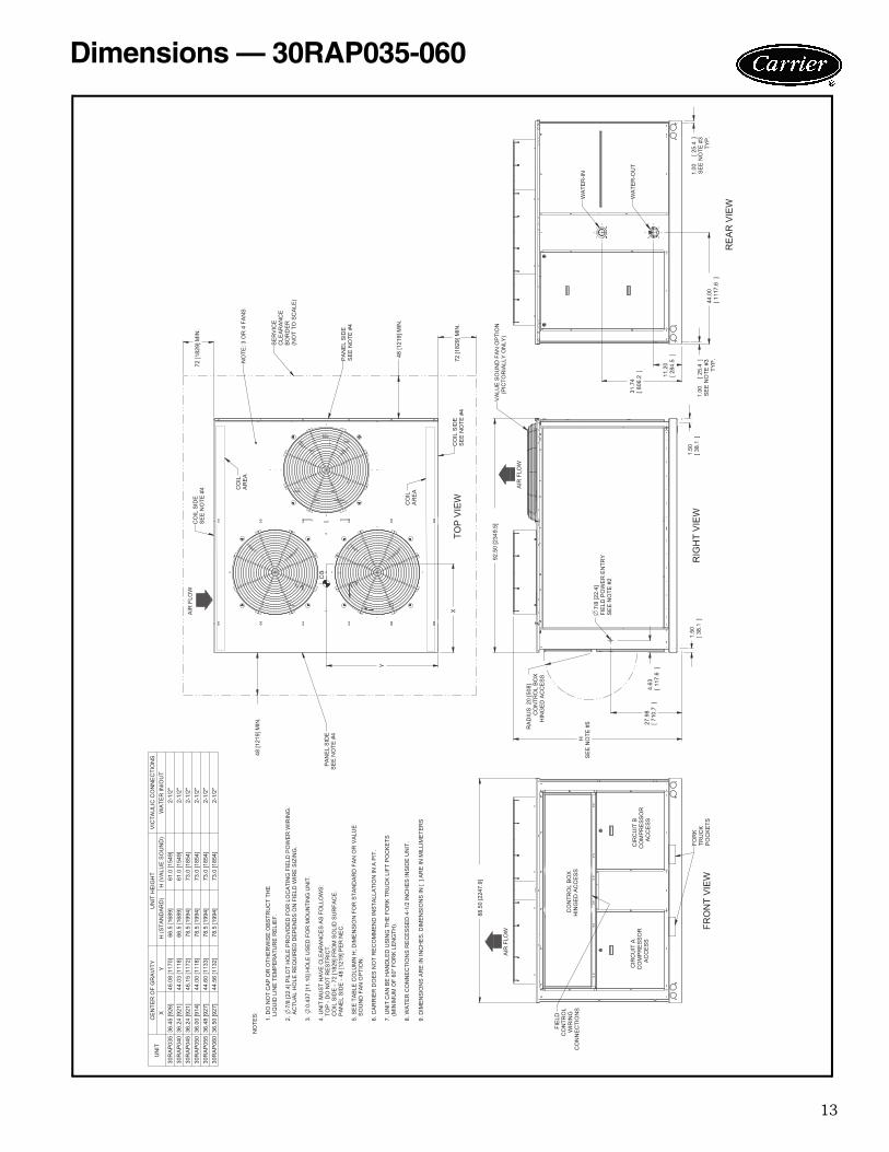
Dimensions — 30RAP035-060
14
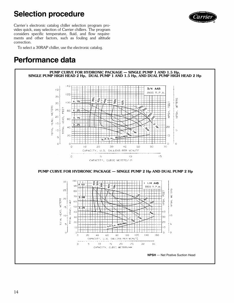
Carrier’s electronic catalog chiller selection program pro-vides quick, easy selection of Carrier chillers. The programconsiders specific temperature, fluid, and flow require-ments and other factors, such as fouling and altitudecorrection.
To select a 30RAP chiller, use the electronic catalog.
Performance data
PUMP CURVE FOR HYDRONIC PACKAGE — SINGLE PUMP 1 AND 1.5 Hp,SINGLE PUMP HIGH HEAD 2 Hp, DUAL PUMP 1 AND 1.5 Hp, AND DUAL PUMP HIGH HEAD 2 Hp
PUMP CURVE FOR HYDRONIC PACKAGE — SINGLE PUMP 2 Hp AND DUAL PUMP 2 Hp
NPSH — Net Postive Suction Head
Selection procedure

15
TO
TAL
HE
AD
INF
EE
T
TO
TAL
HE
AD
INM
ET
ER
S
NP
SH
INM
ET
ER
S
NP
SH
INF
EE
T
CAPACITY IN CUBIC METERS/HR
CAPACITY IN U.S. GALLONS PER MINUTE
11/ 4AC3500 R.P.M.
-
TO
TAL
HE
AD
INF
EE
T
TO
TAL
HE
AD
INM
ET
ER
S
CAPACITY IN CUBIC METERS/HR
CAPACITY IN U.S. GALLONS PER MINUTE
11/ 2AC3500 R.P.M.
NP
SH
INM
ET
ER
S
NP
SH
INF
EE
T
PUMP CURVE FOR HYDRONIC PACKAGE — SINGLE PUMP 5 Hp AND DUAL PUMP 5 Hp
NPSH — Net Postive Suction Head
PUMP CURVE FOR HYDRONIC PACKAGE — SINGLE PUMP HIGH HEAD 5 Hp AND DUAL PUMP HIGH HEAD 5 Hp
PUMP CURVE FOR HYDRONIC PACKAGE — SINGLE PUMP 7.5 Hp AND DUAL PUMP 7.5 Hp
a30-4865
a30-4866
Performance data (cont)

16
501 2 543
40
45
6
30
35
rop
(ft w
g)
20
25
ater
Pre
ssur
e D
10
15
Wa
0
5
0 10 20 30 40 50 60 70 80 90 1000 10 20 30 40 50 60 70 80 90 100GPM
20
25
30
35
40
45
50
ater
Pre
ssur
e D
rop
(ft w
g)
11
109
8
7
12
0
5
10
15
0 20 40 60 80 100 120 140 160
Wa
GPM
PRESSURE DROP, WITHOUT PUMP UNITS, 30RAP010-030 (English)
PRESSURE DROP, WITHOUT PUMP UNITS, 30RAP035-060 (English)
LEGEND1 — 30RAP010 3 — 30RAP018 5 — 30RAP025 7 — 30RAP035 9 — 30RAP045 11 — 30RAP0552 — 30RAP015 4 — 30RAP020 6 — 30RAP030 8 — 30RAP040 10 — 30RAP050 12 — 30RAP060
NOTES:1. Use the following formula to convert feet of water to psig:
ft of water (.4335) = psig2. Use the following formula to convert psig to feet of water:
psig (2.306) = ft of water
a30-4874
a30-4875
Performance data (cont)
17
1401 2 543 6
120
80
100
p (k
Pa)
60
80
er P
ress
ure
Dro
p
40
Wat
e
0
20
0 1 2 3 4 5 6 7 8 90 1 2 3 4 5 6 7 8 9Liters/Second
60
80
100
120
140
r Pre
ssur
e D
rop
(kPa
)
11
1098
7
12
0
20
40
0 1 2 3 4 5 6 7 8 9 10
Wat
er
Liters/Second
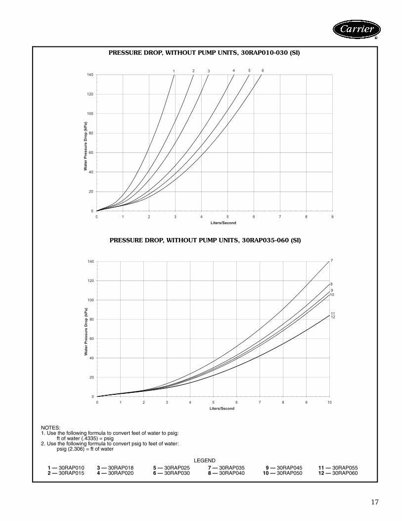
PRESSURE DROP, WITHOUT PUMP UNITS, 30RAP010-030 (SI)
PRESSURE DROP, WITHOUT PUMP UNITS, 30RAP035-060 (SI)
LEGEND1 — 30RAP010 3 — 30RAP018 5 — 30RAP025 7 — 30RAP035 9 — 30RAP045 11 — 30RAP0552 — 30RAP015 4 — 30RAP020 6 — 30RAP030 8 — 30RAP040 10 — 30RAP050 12 — 30RAP060
NOTES:1. Use the following formula to convert feet of water to psig:
ft of water (.4335) = psig2. Use the following formula to convert psig to feet of water:
psig (2.306) = ft of water
a30-4876
a30-4877

18
AIR FLOW FIELDPOWERSUPPLY
CONTROLWIRING
FLOW
GATEVALVE
VIBRATIONELIMINATOR
VALVEPRESSUREGAGE
SHUT OFFVALVES
HEAT TAPE INSULATION IS RECOMMENDED ON ALL EXPOSED PIPINGIF AMBIENT TEMPERATURE <32 F (0 C) AND NO ANTIFREEZE SOLUTION IS IN SYSTEM
TOEXPANSION
TANK
PUMP
AIR FLOW FIELDPOWERSUPPLY
CONTROLWIRING
FLOW
GATEVALVE
VIBRATIONELIMINATOR
NOTE 5HEAT TAPE INSULATION IS RECOMMENDED ON ALL EXPOSED PIPINGIF AMBIENT TEMPERATURE <32 F (0 C) AND NO ANTIFREEZE SOLUTION IS IN SYSTEM
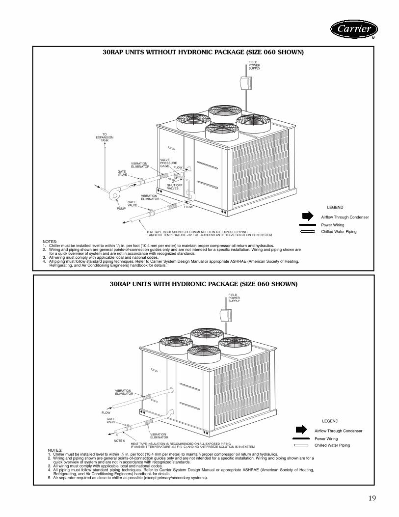
30RAP UNITS WITHOUT HYDRONIC PACKAGE (SIZE 030 SHOWN)
30RAP UNITS WITH HYDRONIC PACKAGE (SIZE 030 SHOWN)
NOTES:1. Chiller must be installed level to within 1/8 in. per foot (10.4 mm per meter) to maintain proper compressor oil return and hydraulics.2. Wiring and piping shown are general points-of-connection guides only and are not intended for a specific installation. Wiring and piping shown are
for a quick overview of system and are not in accordance with recognized standards.3. All wiring must comply with applicable local and national codes.4. All piping must follow standard piping techniques. Refer to Carrier System Design Manual or appropriate ASHRAE (American Society of Heating,
Refrigerating, and Air Conditioning Engineers) handbook for details.
LEGEND
Airflow Through Condenser
Power Wiring
Chilled Water Piping
LEGEND
Airflow Through Condenser
Power Wiring
Chilled Water Piping
NOTES:1. Chiller must be installed level to within 1/8 in. per foot (10.4 mm per meter) to maintain proper compressor oil return and hydraulics.2. Wiring and piping shown are general points-of-connection guides only and are not intended for a specific installation. Wiring and piping shown are for a
quick overview of system and are not in accordance with recognized standards.3. All wiring must comply with applicable local and national codes.4. All piping must follow standard piping techniques. Refer to Carrier System Design Manual or appropriate ASHRAE (American Society of Heating,
Refrigerating, and Air Conditioning Engineers) handbook for details.5. Air separator required as close to chiller as possible (except primary/secondary systems).
a30-4867
a30-4868
Typical piping and wiring
19
FLOWGATEVALVE
VIBRATIONELIMINATOR
TOEXPANSION
TANK
PUMP
HEAT TAPE INSULATION IS RECOMMENDED ON ALL EXPOSED PIPINGIF AMBIENT TEMPERATURE <32 F (0 C) AND NO ANTIFREEZE SOLUTION IS IN SYSTEM
FLOW
GATEVALVE
VIBRATIONELIMINATOR
VALVEPRESSUREGAGE
SHUT OFFVALVES
FIELDPOWERSUPPLY
GATEVALVE
VIBRATIONELIMINATOR
NOTE 5HEAT TAPE INSULATION IS RECOMMENDED ON ALL EXPOSED PIPINGIF AMBIENT TEMPERATURE <32 F (0 C) AND NO ANTIFREEZE SOLUTION IS IN SYSTEM
FLOW
VIBRATIONELIMINATOR
FIELDPOWERSUPPLY
30RAP UNITS WITHOUT HYDRONIC PACKAGE (SIZE 060 SHOWN)
30RAP UNITS WITH HYDRONIC PACKAGE (SIZE 060 SHOWN)
NOTES:1. Chiller must be installed level to within 1/8 in. per foot (10.4 mm per meter) to maintain proper compressor oil return and hydraulics.2. Wiring and piping shown are general points-of-connection guides only and are not intended for a specific installation. Wiring and piping shown are
for a quick overview of system and are not in accordance with recognized standards.3. All wiring must comply with applicable local and national codes.4. All piping must follow standard piping techniques. Refer to Carrier System Design Manual or appropriate ASHRAE (American Society of Heating,
Refrigerating, and Air Conditioning Engineers) handbook for details.
LEGEND
Airflow Through Condenser
Power Wiring
Chilled Water Piping
LEGEND
Airflow Through Condenser
Power Wiring
Chilled Water PipingNOTES:1. Chiller must be installed level to within 1/8 in. per foot (10.4 mm per meter) to maintain proper compressor oil return and hydraulics.2. Wiring and piping shown are general points-of-connection guides only and are not intended for a specific installation. Wiring and piping shown are for a
quick overview of system and are not in accordance with recognized standards.3. All wiring must comply with applicable local and national codes.4. All piping must follow standard piping techniques. Refer to Carrier System Design Manual or appropriate ASHRAE (American Society of Heating,
Refrigerating, and Air Conditioning Engineers) handbook for details.5. Air separator required as close to chiller as possible (except primary/secondary systems).
a30-4869
a30-4870

20
89
10
12 11
14
12 11
13
2
1
3
4
5 6
7
6
TYPICAL PIPING DIAGRAM ON 30RAP UNITS WITH HYDRONIC PACKAGE
LEGEND
1 — Strainer/Blow-Down Valve2 — Expansion Tank3 — Pump4 — Electric Heater5 — Air Vent Connection Port6 — Pressure/Temperature Access Port7 — Heat Exchanger
8 — Flow Switch9 — Balance Valve/Drain Plug
10 — Pressure Relief11 — Isolation Valves12 — Flex Connections13 — Pressure Reducing/Fill Valve14 — Air Separator and Vent
--- Factory Supplied
a30-4871
Typical piping and wiring (cont)

21
30RAP ELECTRICAL DATA
LEGEND
NOTES:1. Units are suitable for use on electrical systems where voltage supplied to the unit terminals
is not below or above the listed minimum and maximum limits. Maximum allowable phaseimbalance is: voltage, 2%; amps 10%.
2. All units/modules have single point primary power connection. (Each unit/module requiresits own power supply.) Main power must be supplied from a field-supplied disconnect.
3. Cooler heater is wired into the control circuit so it is always operable as long as the powersupply disconnect is on, even if any safety device is open.
4. Power draw control circuits include cooler heaters (where used).
UNIT30RAP
UNIT VOLTAGE POWERSUPPLY
QTYREQD.
NO HYDRONIC PACKAGESTANDARD AEROACOUSTIC™ FAN
NO HYDRONIC PACKAGEOPTIONAL VALUE SOUND FANS
V-Hz(3 Ph)
Supplied MCA MOCP ICF RecFuseSize
MCA MOCP ICF RecFuseSizeMin Max XL XL XL XL XL XL
010
208/230-60 187 253 1 66.1 110 251.0 80 66.7 110 251.6 80460-60 414 506 1 26.2 40 127.9 35 26.6 45 128.3 35575-60 518 633 1 20.8 35 102.4 25 21.0 35 102.6 25380-60 342 418 1 33.5 50 148.9 40 33.5 50 148.9 40
015
208/230-60 187 253 1 75.8 125 346.0 90 76.4 125 346.6 100460-60 414 506 1 36.5 60 181.9 45 36.9 60 182.3 45575-60 518 633 1 32.0 50 134.4 40 32.2 50 134.6 40380-60 342 418 1 46.4 80 199.9 60 46.4 80 199.9 60
018
208/230-60 187 253 1 87.2 110 270.4 100 88.4 110 271.6 100460-60 414 506 1 43.4 60 136.5 50 44.2 60 137.3 50575-60 518 633 1 34.9 45 98.2 40 35.3 45 98.6 40380-60 342 418 1 51.1 70 167.0 60 51.1 70 167.0 60
020
208/230-60 187 253 1 92.6 125 286.8 110 93.8 125 288.0 110460-60 414 506 1 46.1 60 148.7 60 46.9 60 149.5 60575-60 518 633 1 37.0 50 99.1 45 37.4 50 99.5 45380-60 342 418 1 61.2 80 176.5 70 61.2 80 176.5 70
025
208/230-60 187 253 1 127.4 175 363.3 150 128.6 175 364.5 150460-60 414 506 1 57.8 80 178.9 70 58.6 80 179.7 70575-60 518 633 1 49.8 60 133.7 60 50.0 60 134.1 60380-60 342 418 1 68.3 90 173.7 80 68.3 90 173.7 80
030
208/230-60 187 253 1 137.6 175 407.8 175 138.8 175 409.0 175460-60 414 506 1 66.3 90 211.7 80 67.1 90 212.5 80575-60 518 633 1 58.1 80 160.5 70 58.5 80 160.9 70380-60 342 418 1 84.3 110 237.8 100 84.3 110 237.8 100
035
208/230-60 187 253 1 165.4 200 341.6 175 167.2 200 341.6 200460-60 414 506 1 82.4 100 176.3 90 83.6 100 176.3 90575-60 518 633 1 66.1 80 121.0 70 66.7 80 121.0 80380-60 342 418 1 103.5 125 207.2 110 103.5 125 207.2 110
040
208/230-60 187 253 1 194.8 225 377.0 225 196.6 225 377.0 225460-60 414 506 1 86.2 100 180.1 100 87.4 100 180.1 100575-60 518 633 1 68.8 80 143.7 80 69.4 80 143.7 80380-60 342 418 1 112.5 125 216.1 125 112.5 125 216.1 125
045
208/230-60 187 253 1 229.6 250 450.7 250 231.4 250 450.7 250460-60 414 506 1 97.9 110 214.8 110 99.1 110 214.8 110575-60 518 633 1 81.4 100 163.5 90 82.0 100 163.5 90380-60 342 418 1 119.6 125 216.5 125 119.6 125 216.5 125
050
208/230-60 187 253 1 236.0 250 453.9 250 237.8 250 453.9 250460-60 414 506 1 106.9 125 219.3 125 108.1 125 219.3 125575-60 518 633 1 91.8 110 168.7 100 92.4 110 168.7 100380-60 342 418 1 126.0 150 219.7 150 126.0 150 219.7 150
055
208/230-60 187 253 1 252.2 300 502.9 300 254.6 300 502.9 300460-60 414 506 1 118.3 125 255.9 125 119.9 125 255.9 125575-60 518 633 1 102.7 125 199.3 110 103.5 125 199.3 110380-60 342 418 1 145.9 175 290.9 175 145.9 175 290.9 175
060
208/230-60 187 253 1 261.2 317 507.4 300 263.6 320 507.4 300460-60 414 506 1 125.9 150 259.7 150 127.5 150 259.7 150575-60 518 633 1 110.3 125 203.1 125 111.1 125 203.1 125380-60 342 418 1 160.1 175 298.0 175 160.1 175 298.0 175
ICF — Instantaneous Current Flow MOCP — Maximum Overcurrent ProtectionMCA — Minimum Circuit Amps XL — Across-the-Line Start
Electrical data

22
FAN ELECTRICAL DATA(Standard AeroAcoustic™ Fans)
LEGENDFLA — Full Load Amps
FAN ELECTRICAL DATA(Optional Value Sound Fans)
UNIT30RAP
UNIT VOLTAGEV-Hz (3 Ph)
STANDARD CONDENSER FANS
Quantity FLA(each)
010
208/230-60 1 6.0460-60 1 2.9575-60 1 2.4380-60 1 3.9
015
208/230-60 1 6.0460-60 1 2.9575-60 1 2.4380-60 1 3.9
018
208/230-60 2 6.0460-60 2 2.9575-60 2 2.4380-60 2 3.9
020
208/230-60 2 6.0460-60 2 2.9575-60 2 2.4380-60 2 3.9
025
208/230-60 2 6.0460-60 2 2.9575-60 2 2.4380-60 2 3.9
030
208/230-60 2 6.0460-60 2 2.9575-60 2 2.4380-60 2 3.9
035
208/230-60 3 6.0460-60 3 2.9575-60 3 2.4380-60 3 3.9
040
208/230-60 3 6.0460-60 3 2.9575-60 3 2.4380-60 3 3.9
045
208/230-60 3 6.0460-60 3 2.9575-60 3 2.4380-60 3 3.9
050
208/230-60 3 6.0460-60 3 2.9575-60 3 2.4380-60 3 3.9
055
208/230-60 4 6.0460-60 4 2.9575-60 4 2.4380-60 4 3.9
060
208/230-60 4 6.0460-60 4 2.9575-60 4 2.4380-60 4 3.9
UNIT30RAP
UNIT VOLTAGEV-Hz (3 Ph)
OPTIONAL CONDENSER FANS
Quantity FLA(each)
010
208/230-60 1 6.6460-60 1 3.3575-60 1 2.6380-60 1 3.9
015
208/230-60 1 6.6460-60 1 3.3575-60 1 2.6380-60 1 3.9
018
208/230-60 2 6.6460-60 2 3.3575-60 2 2.6380-60 2 3.9
020
208/230-60 2 6.6460-60 2 3.3575-60 2 2.6380-60 2 3.9
025
208/230-60 2 6.6460-60 2 3.3575-60 2 2.6380-60 2 3.9
030
208/230-60 2 6.6460-60 2 3.3575-60 2 2.6380-60 2 3.9
035
208/230-60 3 6.6460-60 3 3.3575-60 3 2.6380-60 3 3.9
040
208/230-60 3 6.6460-60 3 3.3575-60 3 2.6380-60 3 3.9
045
208/230-60 3 6.6460-60 3 3.3575-60 3 2.6380-60 3 3.9
050
208/230-60 3 6.6460-60 3 3.3575-60 3 2.6380-60 3 3.9
055
208/230-60 4 6.6460-60 4 3.3575-60 4 2.6380-60 4 3.9
060
208/230-60 4 6.6460-60 4 3.3575-60 4 2.6380-60 4 3.9
Electrical data (cont)

23
PUMP ELECTRICAL DATA
LEGEND
NOTES:1. Units are suitable for use on electrical systems where voltage supplied
to the unit terminals is not below or above the listed minimum and max-imum limits. Maximum allowable phase imbalance is: voltage, 2%;amps 10%.
2. All units/modules have single point primary power connection. (Eachunit/module requires its own power supply.) Main power must be sup-plied from a field-supplied disconnect.
3. The unit control circuit power transformer (24 v, single-phase for allvoltages) is factory supplied.
4. Cooler heaters are wired into the main power circuit so they are alwaysoperable as long as the disconnect is on, even if any safety device isopen, and the unit ON/OFF switch is in the OFF position.
5. Incoming wire size ranges are shown below:a. Size 010-030 terminal block no. 8 - no. 2/0 AWG (American
Wire Gage)b. Size 035-060 terminal block no. 6 - 350 kcmilc. 60 and 100 amp non-fused disconnect option no. 6 - no. 1 AWGd. 250 amp non-fused disconnect option no. 6 AWG - 350 kcmil
PUMPOPTION
PUMPSIZE
PUMPRPM
UNIT VOLTAGEV-Hz (3 Ph)
FLA(each)
LRA(each)
1, 8 1.0 HP
3500 208/230-60 N/A N/A3500 460-60 N/A N/A3500 575-60 N/A N/A3500 380-60 N/A N/A
2, 9 1.5 HP
3500 208/230-60 N/A N/A3500 460-60 N/A N/A3500 575-60 N/A N/A3500 380-60 N/A N/A
3, 4, B, C 2.0 HP
3500 208/230-60 N/A N/A3500 460-60 N/A N/A3500 575-60 N/A N/A3500 380-60 N/A N/A
5, 6, D, F 5.0 HP
3500 208/230-60 N/A N/A3500 460-60 N/A N/A3500 575-60 N/A N/A3500 380-60 N/A N/A
7, G 7.5 HP
3500 208/230-60 N/A N/A3500 460-60 N/A N/A3500 575-60 N/A N/A3500 380-60 N/A N/A
FLA — Full Load AmpsLRA — Locked Rotor AmpsN/A — Data not available at this time

24
COMPRESSOR ELECTRICAL DATA
LEGEND
* All data is per individual compressor.
UNIT30RAP
NUMBER OFCOMPRESSORS
PER CIRCUIT
UNIT VOLTAGEV-Hz (3 Ph)
CIRCUIT*CIRCUIT A CIRCUIT B
RLA LRA RLA LRA
010 1
208/230-60 48.1 245 — —460-60 18.6 125 — —575-60 14.7 100 — —380-60 23.7 145 — —
015 1
208/230-60 55.8 340 — —460-60 26.9 179 — —575-60 23.7 132 — —380-60 34.0 196 — —
018 2
208/230-60 33.4 225 — —460-60 16.7 114 — —575-60 13.4 80 — —380-60 19.2 140 — —
020 2
208/230-60 35.8 239 — —460-60 17.9 125 — —575-60 14.3 80 — —380-60 23.7 145 — —
025 2
208/230-60 51.3 300 — —460-60 23.1 150 — —575-60 19.9 109 — —380-60 26.9 139 — —
030 2
208/230-60 55.8 340 — —460-60 26.9 179 — —575-60 23.7 132 — —380-60 34.0 196 — —
035 2
208/230-60 35.8 239 33.4 225460-60 17.9 125 16.7 114575-60 14.3 80 13.4 80380-60 23.7 145 19.2 140
040 2
208/230-60 35.8 239 48.1 245460-60 17.9 125 18.6 125575-60 14.3 80 14.7 100380-60 23.7 145 23.7 145
045 2
208/230-60 48.1 245 51.3 300460-60 18.6 125 23.1 150575-60 14.7 100 19.9 109380-60 23.7 145 26.9 139
050 2
208/230-60 51.3 300 51.3 300460-60 23.1 150 23.1 150575-60 19.9 109 19.9 109380-60 26.9 139 26.9 139
055 2
208/230-60 51.3 300 55.8 340460-60 23.1 150 26.9 179575-60 19.9 109 23.7 132380-60 26.9 139 34.0 196
060 2
208/230-60 55.8 340 55.8 340460-60 26.9 179 26.9 179575-60 23.7 132 23.7 132380-60 34.0 196 34.0 196
LRA — Locked Rotor AmpsRLA — Rated Load Amps
Electrical data (cont)

25
Microprocessor — The ComfortLink™ microprocessorcontrols overall unit operation. Its central executive routinecontrols a number of processes simultaneously. Theseinclude internal timers, reading inputs, analog to digitalconversions, fan control, display control, diagnostic con-trol, output relay control, demand limit, capacity control,head pressure control, and temperature reset. Some pro-cesses are updated almost continuously, others every 2 to3 seconds, and some every 30 seconds. The microproces-sor routine is started by switching the Emergency ON-OFFswitch to ON position. Pump control of external pumps(where so configured) or optional internal pump, willenergize the cooler pump to the internal (or CCN) timeschedule (or input occupied signal from external system).
Where dual pumps are utilized, only one pump will beused at a time. The control will start the pump with theleast number of operating hours. When the unit receives acall for cooling (based on a deviation from chilled water setpoint), the unit stages up in capacity to maintain the coolerfluid set point. The first compressor starts 1 to 3 minutesafter the call for cooling. The ComfortLink microproces-sor controls the capacity of the chiller by cycling compres-sors at a rate to satisfy actual dynamic load conditions. Thecontrol maintains leaving-fluid temperature set pointshown on the scrolling marquee display board throughintelligent cycling of compressors. Accuracy depends onloop volume, loop flow rate, load, outdoor-air temperature,number of stages, and particular stage being cycled off. Noadjustment for cooling range or cooler flow rate isrequired, because the control automatically compensatesfor cooling range by measuring both return-fluid tempera-ture and leaving-fluid temperature. This is referred to asleaving-fluid temperature control with return-fluid tempera-ture compensation.
The basic logic for determining when to add or remove astage is a time band integration of deviation from set pointplus rate of change of leaving-fluid temperature. Whenleaving-fluid temperature is close to set point and slowlymoving closer, logic prevents addition of another stage.
If 1° F per minute (0.6° C per minute) pulldown controlhas been selected (adjustable setting), no additional steps ofcapacity are added as long as difference between leaving-fluid temperature and set point is greater than 4° F (2.2° C)and rate of change in leaving-fluid temperature is greaterthan the selected pulldown control rate. If it has been lessthan 90 seconds since the last capacity change, compres-sors will continue to run unless a safety device trips. Thisprevents rapid cycling and also helps return oil during shorton periods.Sensors — Thermistors are used for temperature-sensinginputs to microprocessor. Additional thermistor sensorsmay be used as remote temperature sensors for optionalLCWT (leaving chilled fluid temperature) reset.• Cooler leaving chilled fluid temperature• Cooler entering fluid (return) temperature• Outside air temperature• Compressor suction temperature
Two refrigerant pressure transducers are used in eachcircuit for sensing suction and discharge pressure. The
microprocessor uses these inputs to control capacity, theelectronic expansion valve, and fan cycling.• Saturated condensing temperature• Cooler saturation temperature
Control sequenceOff cycle — If ambient temperature is below 36 F (2 C),cooler heaters (if equipped) are also energized.Start-up — After control circuit switches on, the prestartprocess takes place, then microprocessor checks itself,starts pump (if configured) and waits for temperature tostabilize. The controlled pulldown feature limits compres-sor loading on start-up to reduce demand on start-up andunnecessary compressor usage. The microprocessor limitssupply-fluid temperature decrease (start-up only) to 1° F(0.6° C) per minute.Capacity control — On first call for cooling, micropro-cessor starts initial compressor and fan stage on leadcircuit.
As additional cooling is required, additional compressorsare energized.
Speed at which capacity is added or reduced is con-trolled by temperature deviation from set point and rate oftemperature change of chilled fluid.
The Main Base Board (MBB) responds to temperature ofsupply chilled water to cycle the compressor(s) and to con-trol compressor unloading and loading to match coolingload requirements.
Hot gas bypass valve is energized by the MBB. Valveallows hot gas to pass directly into the cooler circuit on thefinal step of unloading, maintaining constant suction pres-sure and permitting the unit to operate at lower loads withless compressor cycling.
On units equipped with the digital compressor option,the control will intigrate the modulation of the digital com-pressor into the capacity routine to match cooling loadrequirements. The digital compressor will modulate in 13steps for sizes 010 and 015, 22 steps (11 per compressor)for sizes 020-030, and 44 steps (11 per compressor) forsizes 035-060.The digital scroll option provides better capacity control byincrementally modulating capacity effectively, increasingthe number of compression stages compared to chillersthat are not equipped with this option. The digital scrollcompressor is not a variable speed device, it modulates thecapacity output by allowing the scroll sets to separate dur-ing operation, alternating between full capacity and zerocapacity. Utilizing a fixed timeframe ratio, the percentageof time that the scroll set is engaged is the percentagecapacity of that compressor.There are 2 major advantages of this type of capacity con-trol. First, there is closer capacity control operation with allthe available capacity steps compared to the on/off cyclingcontrol of conventional scrolls. Second, there is much lesswear factor on digital scrolls compared to standard scrollcompressors because the digital scrolls are not subject to asmany of the shutdown/restart cycles as conventionalscrolls. Digital scrolls, rather than shutting off, tend toremain on as they vary to deliver the correct capacity step.
Controls
26
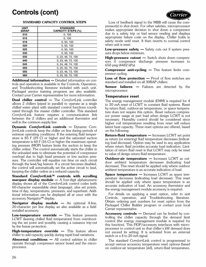
STANDARD CAPACITY CONTROL STEPS
Additional information — Detailed information on con-trols and operation is available in the Controls, Operation,and Troubleshooting literature included with each unit.Packaged service training programs are also available.Contact your Carrier representative for more information.Dual chiller control — The ComfortLink controllerallows 2 chillers (piped in parallel) to operate as a singlechilled water plant with standard control functions coordi-nated through the master chiller controller. This standardComfortLink feature requires a communication linkbetween the 2 chillers and an additional thermistor andwell in the common supply line.Dynamic ComfortLink controls — Dynamic Com-fortLinkcontrols keep the chiller on line during periods ofextreme operating conditions. If the entering fluid temper-ature is 85 F (29 C) or higher and the saturated suctiontemperature is 60 F (16 C) or higher the maximum operat-ing pressure (MOP) feature limits the suction to keep thechiller online. The control automatically starts the chiller inthe unloaded state to eliminate the potential of compressoroverload due to high head pressure or low suction pres-sure. The controller will equalize run time on each circuitthrough the lead/lag feature. If a circuit becomes disabled,the control will automatically set the active circuit to lead,keeping the chiller online at a reduced capacity.Standard ComfortLink™ controls with scrollingmarquee display module — A four-digit alphanumericdisplay shows all of the ComfortLink control codes (with60-character expandable clear language), plus set points,time of day, temperatures, pressures, and superheat. Addi-tional information can be displayed all at once with theaccessory Navigator™ display.Navigator display module — An optional 4-line,20-character per line display an also available as a field-installed accessory.Low-temperature override — This feature preventsLCWT (leaving chilled fluid temperature) from overshoot-ing the set point and possibly causing a nuisance trip-outby the freeze protection.High-temperature override — This feature allowschiller to add capacity quickly during rapid load variations.Abnormal conditions — All control safeties in chilleroperate through compressor sensor board and the micro-processor.
Loss of feedback signal to the MBB will cause the com-pressor(s) to shut down. For other safeties, microprocessormakes appropriate decision to shut down a compressordue to a safety trip or bad sensor reading and displaysappropriate failure code on the display. Chiller holds insafety mode until reset. It then reverts to normal controlwhen unit is reset.Low-pressure safety — Safety cuts out if system pres-sure drops below minimum.High-pressure cutout — Switch shuts down compres-sors if compressor discharge pressure increases to650 psig (4482 kPa).Compressor anti-cycling — This feature limits com-pressor cycling.Loss of flow protection — Proof of flow switches arestandard and installed on all 30RAP chillers.Sensor failures — Failures are detected by themicroprocessor.
Temperature resetThe energy management module (EMM) is required for 4to 20 mA reset of LCWT in constant fluid systems. Resetby return fluid, outdoor-air temperature, or space tempera-ture does not require this option. Reset reduces compres-sor power usage at part load when design LCWT is notnecessary. Humidity control should be considered sincehigher coil temperatures resulting from reset will reducelatent heat capacity. Three reset options are offered, basedon the following:Return-fluid temperature — Increases LCWT set pointas return (or entering) fluid temperature decreases (indicat-ing load decrease). Option may be used in any applicationwhere return fluid provides accurate load indication. Limi-tation of return fluid reset is that LCWT may only be resetto value of design return fluid temperature.Outdoor-air temperature — Increases LCWT as out-door ambient temperature decreases (indicating loaddecrease). This reset should be applied only where outdoorambient temperature is an accurate indication of load.Space temperature — Increases LCWT as space tem-perature decreases (indicating load decrease). This resetshould be applied only where space temperature is anaccurate indication of load. An accessory thermistor andthe energy management module accessory is required.
For details on applying a reset option, refer to unitControls, operation, and Troubleshooting literature.Obtain ordering part numbers for reset option from thePackaged Chiller Builder program or contact your localCarrier representative.Accessory controls — Demand can be limited by con-trolling the chiller capacity through the demand limitcontrol (the energy management module is required forthis function). This FIOP/accessory interfaces with micro-processor to control unit so that chiller’s kW demand doesnot exceed its setting. It is activated from an externalswitch or a 4 to 20 mA signal.
The standard ComfortLink control is programmed toaccept various accessory temperature reset options (basedon outdoor-air temperature [std], return-fluid temperature,
UNIT30RAP
STANDARDCAPACITY STEPS (%)
010 0, 100015 0, 100018 0, 50, 100020 0, 50, 100025 0, 50, 100030 0, 50, 100035 0, 23, 46, 73, 100040 0, 23, 46, 73, 100045 0, 24, 48, 74, 100050 0, 25, 50, 75, 100055 0, 23, 46, 73, 100060 0, 25, 50, 75, 100
Controls (cont)

27
or space temperature), that reset the LCWT. An accessorythermistor for space temperature reset is required. Theenergy management module (EMM) is only required fortemperature reset that is initiated by a 4 to 20 mA signal.Demand limit — If applied, the demand limit functionlimits the total power draw of unit to selected point by con-trolling number of operational compressors during periodsof peak electrical demand.
The energy management module is required for either 2-stage or 4 to 20 mA demand limit.Electronic expansion valve (EXV) — The EXV con-trols refrigerant flow to the cooler for different operatingconditions by moving an orifice to increase or decrease theflow area through the valve based on microprocessorinput. The orifice is positioned by a stepper motor and ismonitored every 3 seconds. The EXV maintains approxi-mately 9° F (5° C) refrigerant superheat entering thecompressor.Diagnostics — The microprocessor may be put througha service test (see Controls, Operation, and Troubleshoot-ing literature). Service test confirms microprocessor isfunctional, informs observer through display the conditionof each sensor and switch in chiller, and allows observer tocheck for proper operation of fans and compressors.Default settings — To facilitate quick start-ups, 30RAPchillers with ComfortLink controls are pre-configured witha default setting that assumes stand-alone operation sup-plying 44 F (6.7 C) chilled water.
Configuration settings will be based on any optionsor accessories included with the unit at the time ofmanufacturing.
Date and time are set to U.S.A. Eastern Time zone andwill need reconfiguring based on location and local timezone. If operation based on occupancy scheduling isdesired, this will also need to be set during installation.Ice duty — ComfortLink controls have the capability ofreduced leaving fluid temperature operation for thermalstorage, or ice duty. The optional energy managementmodule includes input contacts for the “ice done” signalgenerated by the thermal storage control system. The iceduty feature may be configured to start on an externalinput command or by the ComfortLink standard internalscheduling function. Ice duty may be used in combinationwith any other standard features offered by the energymanagement module and ComfortLink controls.
The production of ice, which is stored for peak coolingdemands, can significantly decrease energy costs. The unitproduces ice (normally at night) by supplying ice storagetanks with low temperature cooling fluid. The chiller takesadvantage of reduced ambient conditions at night for ice-making mode, so the capacity suffers a lower penalty forthe low leaving fluid temperatures.
At peak cooling demands the chiller and the stored icemay share the cooling load to reduce operating costs. Thethermal storage system may potentially reduce the size ofthe chiller plant required to meet demand loads.
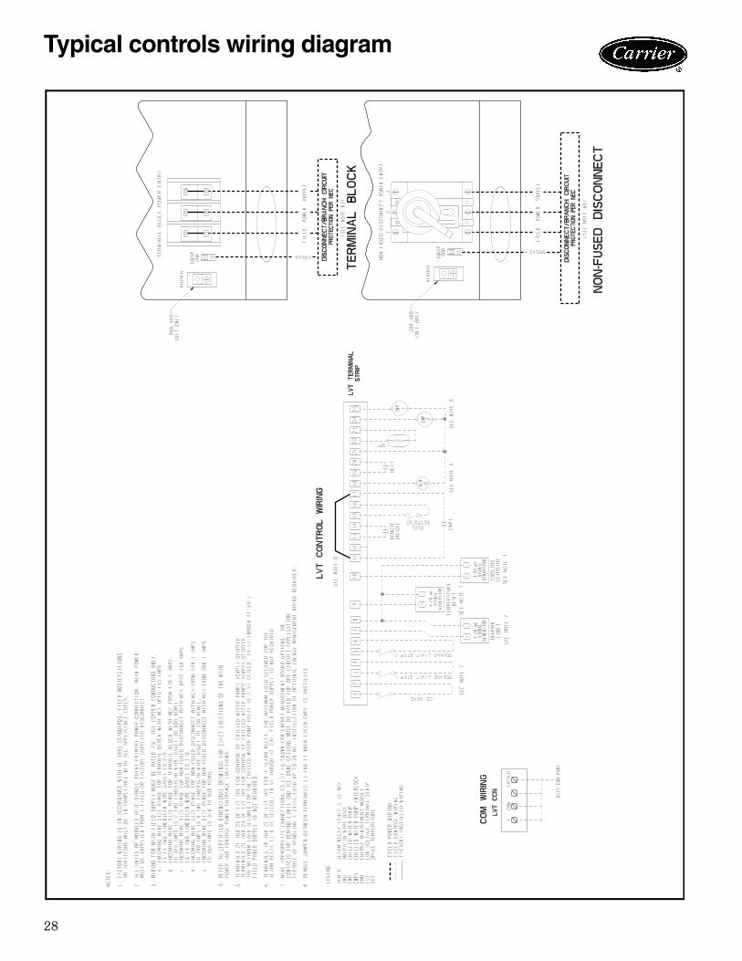
28
a30-4872
Typical controls wiring diagram
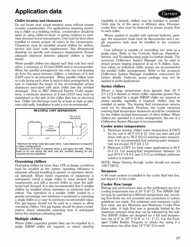
29
Chiller location and clearancesDo not locate near sound sensitive areas without properacoustic consideration. For applications requiring mount-ing a chiller on a building rooftop, consideration should begiven to using rubber-in-shear or spring isolators to mini-mize structure-borne transmission. Unit must be level wheninstalled to ensure proper oil return to the compressors.Clearances must be provided around chillers for airflow,service and local code requirements. See dimensionaldrawings for specific unit clearance requirements. Ensureadequate clearance between adjacent chillers is main-tained.When parallel chillers are aligned such that coils face eachother, a minimum of 10 feet (3048 mm) is recommended.When the parallel arrangement has only one coil drawingair from the space between chillers, a minimum of 6 feet(1829 mm) is recommended. When parallel chillers haveno coils facing each other (a back-to-back arrangement), besure to maintain the larger of the recommended serviceclearances associated with each chiller (see the certifieddrawings). Due to NEC (National Electric Code) regula-tions, a minimum clearance of 4 feet (1219 mm) must bemaintained on the side of the chiller than has an electricalbox. Chiller fan discharge must be at least as high as adja-cent solid walls. Installation in pits is not recommended.
Oversizing chillersOversizing chillers by more than 15% at design conditionsmust be avoided as the system operating efficiency isadversely affected (resulting in greater or excessive electri-cal demand). When future expansion of equipment isanticipated, install a single chiller to meet present loadrequirements and add a second chiller to meet the addi-tional load demand. It is also recommended that 2 smallerchillers be installed where operation at minimum load iscritical. The operation of a smaller chiller loaded to agreater percentage over minimum is preferred to operatinga single chiller at or near its minimum recommended value.Hot gas bypass should not be used as a means to allowoversizing chillers. Hot gas bypass should be given consid-eration where substantial operating time is anticipatedbelow the minimum unloading step.
Multiple chillersWhere chiller capacities greater than can be supplied by asingle 30RAP chiller are required, or where stand-by
capability is desired, chillers may be installed in parallel.Units may be of the same or different sizes. However,cooler flow rates must be balanced to ensure proper flowto each chiller.
Where applied in parallel with optional hydronic pack-age, the expansion tanks must be disconnected and a sin-gle expansion tank must be installed in the commonheader.
Unit software is capable of controlling two units as asingle plant. Refer to the Controls, Start-up, Operation,Service, and Troubleshooting guide for further details. Theaccessory Chillervisor System Manager can be used toensure proper staging sequence of up to 8 chillers. Isola-tion valves on individual chiller pumps are recommendedfor parallel chiller arrangements. Refer to the accessoryChillervisor System Manager installation instructions forfurther details. Hydronic pump package may not beapplied in series applications.
Series chillers Where a large temperature drop (greater than 20 F[11.1 C]) is desired or where chiller capacities greater thancan be supplied by a single 30RAP chiller are required orwhere standby capability is required, chillers may beinstalled in series. The leaving fluid temperature sensorsneed not be relocated. However, the cooler minimumentering fluid temperature limitations should be consideredfor the chillers located downstream of other chillers. Whenchillers are operated in a series arrangement, the use of aChillervisor System Manager is recommended.
Cooler water temperature1. Maximum leaving chilled water temperature (LCWT)
for the unit is 60 F (15.6 C). Unit can start and pulldown with up to 95 F (35 C) entering-water tempera-ture. It is recommended that entering-water tempera-ture not exceed 70 F (21.1 C).
2. Minimum LCWT for fresh water applications is 40 F(3.3 C). For leaving-fluid temperatures between 15and 39.9 F (–9.4 C and 3.3 C) an inhibited antifreezesolution is required.
NOTE: Water flowing through cooler should not exceed100 F (38 C).
StrainersA 40 mesh strainer is installed in the cooler fluid inlet line,just ahead of to the cooler.
Cooler flow/rangeRatings and performance data in this publication are for acooling temperature rise of 10° F (6° C). The 30RAP chill-ers may be operated at a different temperature rise, provid-ing flow limits are not exceeded and corrections to systemguidelines are made. For minimum and maximum coolerflow rates, see the Minimum and Maximum Cooler FlowRates table. A high flow rate is generally limited by themaximum pressure drop that can be tolerated by the unit.The 30RAP chillers are designed for a full load tempera-ture rise of 5° to 20° F (2.8° to 11. 1° C). Use the Pack-aged Chiller Builder Program to obtain the rating if atemperature rise other than 10° F (6° C) is used.
10 ft(3 m)
MINIMUM*
6 ft (1.8 m)MINIMUM†
MULTIPLE UNIT SEPARATION
* Minimum for when coils face each other. Less clearance is requiredin other configurations.† Clearance of 6 feet is required when a coil faces the wall. Whenthere is no coil facing the wall, see the certified drawing for therequired service clearance.
a30-4873
Application data
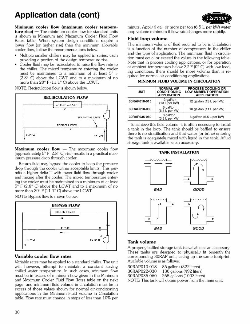
30
Minimum cooler flow (maximum cooler tempera-ture rise) — The minimum cooler flow for standard unitsis shown in Minimum and Maximum Cooler Fluid FlowRates table. When system design conditions require alower flow (or higher rise) than the minimum allowablecooler flow, follow the recommendations below.• Multiple smaller chillers may be applied in series, each
providing a portion of the design temperature rise.• Cooler fluid may be recirculated to raise the flow rate to
the chiller. The mixed temperature entering the coolermust be maintained to a minimum of at least 5° F(2.8° C) above the LCWT and to a maximum of nomore than 20° F (11.1° C) above the LCWT.
NOTE: Recirculation flow is shown below.
Maximum cooler flow — The maximum cooler flow(approximately 5° F [2.8° C] rise) results in a practical max-imum pressure drop through cooler.
Return fluid may bypass the cooler to keep the pressuredrop through the cooler within acceptable limits. This per-mits a higher delta T with lower fluid flow through coolerand mixing after the cooler. The mixed temperature enter-ing the cooler must be maintained to a minimum of at least5° F (2.8° C) above the LCWT and to a maximum of nomore than 20° F (11.1° C) above the LCWT.NOTE: Bypass flow is shown below.
Variable cooler flow ratesVariable rates may be applied to a standard chiller. The unitwill, however, attempt to maintain a constant leavingchilled water temperature. In such cases, minimum flowmust be in excess of minimum flow given in the Minimumand Maximum Cooler Fluid Flow Rates table on the nextpage, and minimum fluid volume in circulation must be inexcess of those values shown for normal air-conditioningapplications in the Minimum Fluid Volume in Circulationtable. Flow rate must change in steps of less than 10% per
minute. Apply 6 gal. or more per ton (6.5 L per kW) waterloop volume minimum if flow rate changes more rapidly.
Fluid loop volumeThe minimum volume of fluid required to be in circulationis a function of the number of compressors in the chillerand the type of application. The minimum fluid in circula-tion must equal or exceed the values in the following table.Note that in process cooling applications, or for operationat ambient temperatures below 32 F (0° C) with low load-ing conditions, there should be more volume than is re-quired for normal air-conditioning applications.
MINIMUM FLUID VOLUME IN CIRCULATION
To achieve this fluid volume, it is often necessary to installa tank in the loop. The tank should be baffled to ensurethere is no stratification and that water (or brine) enteringthe tank is adequately mixed with liquid in the tank. Afluidstorage tank is available as an accessory.
Tank volumeA properly baffled storage tank is available as an accessory.These tanks are designed to physically fit beneath thecorresponding 30RAP unit, taking up the same footprint.Available volume is as follows:30RAP010-018 85 gallons (322 liters)30RAP022-030 130 gallons (492 liters)30RAP035-060 265 gallons (1003 liters)NOTE: This tank will obtain power from the main unit.
RECIRCULATION FLOW
a30-4042
BYPASS FLOW
a30-533
UNITNORMAL AIR
CONDITIONINGAPPLICATION
PROCESS COOLING ORLOW AMBIENT OPERATION
APPLICATION
30RAP010-015 12 gal/ton(13 L per kW) 12 gal/ton (13 L per kW)
30RAP018-030 6 gal/ton(6.5 L per kW) 10 gal/ton (11 L per kW)
30RAP035-060 3 gal/ton(3.3 L per kW) 6 gal/ton (6.5 L per kW)
BAD
BAD
GOOD
GOOD
TANK INSTALLATION
Application data (cont)

31
MINIMUM AND MAXIMUM COOLER FLOW RATES
Cooler fouling factorThe fouling factor used to calculate tabulated ratings is0.00010 ft2 hr °F/Btu (0.000018 m2 °C/W). As foul-ing factor is increased, unit capacity decreases and com-pressor power increases. Use the NACO (North AmericanCommercial Operation) Packaged Chiller Builder for cor-rections to published ratings.
Cooler and hydronic system freeze protectionFreeze protection for down to –20 F (–28.9 C) for thecooler and hydronic package is available as a factory-installed option. Since power is sometimes lost for extend-ed periods during winter storms, freeze protection provid-ed by heater tapes will be effective only if a back-up powersupply can be assured for the unit’s control circuit, heaterand cooler pump. If not protected with an antifreeze solu-tion, draining the cooler and outdoor piping is recom-mended if the system will not be used during freezingweather conditions.
Two conditions that must be considered when determin-ing antifreeze concentration are leaving water set pointand ambient freeze conditions. Both of these parameterscan help determine the recommended concentration level.Higher concentration must be used to adequately protectthe machine.NOTE: Use only antifreeze solutions approved for heat ex-changer duty.
For applications in which the leaving water temperatureset point is less than 40 F (4.4 C), a suitable inhibited anti-freeze solution must be used. The solution concentrationmust be sufficient to protect the chilled water loop to afreeze protection (first crystals) concentration of at least15° F (8.3º C) below the leaving water temperature setpoint.
If the chiller refrigerant or fluid lines are in an area whereambient conditions fall below 34 F (1º C), it is required thatan antifreeze solution be added to protect the unit and fluidpiping to a temperature of 15º F (8.3º C) below the lowestanticipated ambient temperature.
Select concentration based on either burst or freeze pro-tection as dictated by the application. If the chiller does notoperate during the winter, nor is a start-up expected, aburst protection concentration is recommended. This
concentration may not be high enough to pump the fluidthrough the unit. Burst protection is typically a lower con-centration that will provide better performance from themachine. If the chiller does operate during winter, a freezeprotection concentration is recommended. This concentra-tion will be high enough to keep the fluid in a conditionthat it can be pumped at low ambient conditions.
Consult glycol fluid manufacturers for burst protectionrecommendations and fluid specifications.
High ambient temperature operationHigh outdoor ambient chiller start-up and operation is pos-sible for standard 30RAP chillers at ambient temperaturesup to 120 F (50 C) at nominal voltage. The unit will addi-tionally be able to stay running at reduced capacity up to125 F (52 C).
Low ambient temperature operationUnits will operate down to –20 F (–29 C) on size 010 and015 units, 45 F (7 C) on size 018-030 units, and 32 F(0° C) on size 035-060 units as standard.
Operation to –20 F (–29 C) for size 018-060 unitsrequires optional Motormaster® V condenser head pres-sure control (included as standard on size 010 and 015units) as well as wind baffles and hot gas bypass or digitalcompressor option. Inhibited propylene glycol or othersuitable corrosion-resistant anti-freeze solution must befield supplied and installed in all units for unit operationbelow 32 F (0° C). Solution must be added to fluid loop toprotect loop down to 15° F (8° C) below minimum operat-ing ambient temperature. Concentration should be basedon expected minimum temperature and either “Burst” or“Freeze” protection levels. At least 6 gal. per ton (6.5 Lper kW) of fluid volume is the recommended minimum fora moderate system load.NOTE: In order for a chiller to operate at –20 F (–29 C)ambient temperature, the minimum load on the chillermust be above the minimum step of unloading.
30RAPSIZE
MINIMUM COOLER FLOW RATE (gpm)
MAXIMUM COOLER FLOW RATE (gpm)
MINIMUM COOLER FLOW RATE (l/s)
MAXIMUM COOLER FLOW RATE (l/s)
010 13 50 0.8 3.2015 17 66 1.1 4.2018 20 78 1.3 4.9020 23 91 1.5 5.7025 28 112 1.8 7.1030 33 133 2.1 8.4035 41 164 2.6 10.3040 47 186 3.0 11.7045 53 209 3.3 13.2050 57 228 3.6 14.4055 63 251 4.0 15.8060 68 270 4.3 17.0
IMPORTANT: Glycol anti-freeze solutions are highlyrecommended since heater tapes provide no protec-tion in the event of a power failure.
32
NOTE: As an alternative to requiring a glycol solution, thecooler may be remotely located. Burying refrigerant lines isnever permitted.
Altitude correction factorsCorrection factors must be applied to standard ratingsat altitudes above 2000 ft (610 m). Use the NACO Pack-aged Chiller Builder to determine the altitude effect onpeformance.
Water system overview (closed loop systems only)The 30RAP chillers are designed for use with closed sys-tems, meaning that there is no more than one water-airinterface in the water loop. Cooling tower loops, for exam-ple, have two water-air interfaces (sump and nozzles) andwould thus be classified as open, whereas a correctlydesigned chilled water loop with the only water-air inter-face being in the expansion tank is closed. Since closedand open water systems behave very differently, the follow-ing assumes that the chilled water loop is closed. A systeminstalled incorrectly such that air is not handled properly —pipe leaks, vent leaks, air in pipes, etc. — may behave asan open system and thus have unsatisfactory operation.Pump seal wear can also cause leaks that cause poor sys-tem operation. Proper closed system design and installation proceduresshould be followed closely. The system must be con-structed with pressure tight components and thoroughlytested for installation leaks. Factory-supplied hydronic sys-tems are available with single or dual (for back-up) pumps.The factory-installed system includes all of the componentswithin the dashed lines shown in the figure on page 18. Installation of water systems should follow sound engi-neering practice as well as applicable local and industrystandards. Improperly designed or installed systems maycause unsatisfactory operation and/or system failure. Con-sult a water treatment specialist or appropriate literaturefor information regarding filtration, water treatment, andcontrol devices. A typical installation with components thatmight be installed with the hydronic package of the 30RAPunit is shown on pages 16 and 17. It is recommended that isolation (shutoff) valves be placedexterior to the unit to allow removal and service of theentire pump assembly, if necessary. Also, if the unit is iso-lated with valves, a properly sized pressure relief valveshould be installed in the piping between the unit and thevalves, following all applicable state and local codes.
Water system cleaningProper water system cleaning is of vital importance. Exces-sive particulates in the water system can cause excessive
pump seal wear, reduce or stop flow, and cause damage ofother components. Water quality should be maintainedwithin the limits indicated in the Water Quality Characteris-tics and Limitations Table.
1. Install a temporary bypass around the chiller to avoidcirculating dirty water and particulates into the pumppackage and chiller during the flush. Use a temporarycirculating pump during the cleaning process. Also,be sure that there is capability to fully drain the sys-tem after cleaning.
2. Be sure to use a cleaning agent that is compatiblewith all system materials. Be especially careful if thesystem contains any galvanized or aluminum compo-nents. Both detergent-dispersant and alkaline-disper-sant cleaning agents are available.
3. It is a good idea to fill the system through a watermeter. This provides a reference point for the futurefor loop volume readings, but it also establishes thecorrect quantity of cleaner needed in order to get therequired concentration.
4. Use a feeder/transfer pump to mix the solution andfill the system. Circulate the cleaning system for thelength of time recommended by the cleaning agentmanufacturer.a. After cleaning, drain the cleaning fluid and flush
the system with fresh water.b. A slight amount of cleaning residue in the system
can help keep the desired, slightly alkaline, waterpH of 8 to 9. Avoid a pH greater than 10, sincethis will adversely affect pump seal components.
c. A side stream filter is recommended during thecleaning process. Filter side flow rate should beenough to filter the entire water volume every 3 to4 hours. Change filters as often as necessary dur-ing the cleaning process.
d. Remove temporary bypass when cleaning iscomplete.
A strainer with a blow-down valve is standard on all 30RAunits, both with and without hydronic packages. The blow-down valve allows removal of particulates caught in thestrainer without complete removal of the screen. A femaleNPT connection is provided on the valve, allowing hoseconnection for drainage outside the unit. The ComfortLink™ controls provided have a built-in fea-ture to remind building owners or operators to clean thestrainer by discharging the blow-down valve at a pre-settime interval. Properly installed and cleaned systems willrarely need the strainer cleaned after the initial fill. Thistime interval is user-configurable.
Application data (cont)
33
WATER QUALITY CHARACTERISTICSAND LIMITATIONS
*Sulfides in the water quickly oxidize when exposed to air, requiring that noagitation occur as the sample is taken. Unless tested immediately at thesite, the sample will require stabilization with a few drops of one Molarzinc acetate solution, allowing accurate sulfide determination up to 24hours after sampling. A low pH and high alkalinity cause system prob-lems, even when both values are within the ranges shown. The term pHrefers to the acidity, basicity, or neutrality of the water supply. Below 7.0,the water is considered to be acidic. Above 7.0, water is considered to bebasic. Neutral water contains a pH of 7.0.
†Dissolved carbon dioxide can either be calculated from the pH and totalalkalinity values, shown below, or measured on the site using a test kit.Dissolved Carbon Dioxide, PPM = TA x 2[(6.3-pH)/0.3] where TA = Total Alka-linity, PPM as CaCO3.
Condenser coil protection (Enviro-Shield™)Refer to the environmental selection guides for more infor-mation. If the standard Novation® (microchannel) coil doesnot meet the corrosion requirements for a given applica-tion, an e-coated Novation coil option is available. For spe-cific geographical recommendations, please refer to theNACO Packaged Chiller Builder program.E-coated Novation® coils have an extremely flexibleand durable epoxy coating uniformly applied to all coil sur-faces. Unlike brittle phenolic dip and bake coatings, e-coatprovides superior protection with unmatched flexibility,edge coverage, metal adhesion, thermal performance andmost importantly, corrosion resistance. E-coated coilsprovide this protection since all coil surfaces are complete-ly encapsulated from environmental contamination.
Electrical/utility interestsEnergy management — Use of energy managementpractices can significantly reduce operating costs, espe-cially during off-peak modes of operation. Demand limitingand temperature reset are 2 techniques for accomplishingefficient energy management. See Demand Limiting (alsocalled load shedding) section on this page for furtherdetails.
Demand limiting (load shedding)When a utility’s demand for electricity exceeds a certainlevel, loads are shed to keep electricity demand below aprescribed maximum level. Typically, this happens on hotdays when air conditioning is most needed. The energymanagement module (EMM) can be added to accomplishthis reduction. Demand may be limited on unit by resetting
fluid temperature, or by unloading the chiller to a givenpredetermined percentage of the load. Demand limit mayalso be driven by an external 4 to 20 mA signal. These fea-tures require a signal from an intelligent central control. Donot cycle demand limiter for less than 10 minutes on and5 minutes off. Duty cycling cycles electrical loads at regularintervals regardless of need. This reduces the electricaloperating costs of building by “fooling” demand indicatingdevices. Duty cycling of compressors or fans is not recom-mended since motor winding and bearing life will sufferfrom constant cycling.
Remote on-off controlRemote on-off control may be applied by hard-wired con-nection (see Controls and Troubleshooting literature) or byconnection to a Carrier Comfort Network® (CCN) system.
Optional hydronic system selectionSelect pump gpm from resulting chiller selection and totalpressure loss in the system plus the chiller internal pressureloss.NOTE: Maximum gpm (L/s), pressure and pump hp mustnot exceed maximum on pump curve.
Pump flow can be reduced by using the factory-suppliedtriple-duty valve up to 10%. Beyond that, impellertrimming is recommended to reduce energy consumption.Follow local codes or ASHRAE 90.1 recommendations.Contact your Carrier representative for specific amount oftrim required.
Expansion tank supplied will allow loop expansion dueto ambient fluctuations for loop volumes of up to the valuesin the table below. If loop volume exceeds the maximumloop volume, a larger expansion tank must be fieldsupplied.
The supplied expansion tanks have the following specifi-cations: 30RAP010-030 — 5.0 total gal., 2.4 gal. accep-tance volume, 30RAP035-060 — 10.0 total gal., 5.5 gal.acceptance volume.
MAXIMUM LOOP VOLUME
LEGEND
Maximum loop volume is based on typical system pres-sure of 12 psig (83 kPa) and 30 psig (207 kPa) of mini-mum and maximum pressures, and 100 F (37.8 C) meantemperature.
Parallel chillers with hydronic packages require thatpump inlets be equalized to prevent pump cavitation.Pump expansion tanks must be removed and located
WATER CHARACTERISTIC QUALITY LIMITATIONAlkalinity (HCO3-) 70 – 300 ppm
Sulfate (SO42-) Less than 70 ppm
HCO3-/SO42- Greater than 1.0Electrical Conductivity 10 – 500S/cmpH 7.5 – 9.0Ammonium (NH3) Less than 2 ppmChorides (Cl-) Less than 300 ppmFree chlorine (Cl2) Less than 1 ppm
Hydrogen Sulfide (H2S)* Less than 0.05 ppm
Free (aggressive) CarbonDioxide (CO2)†
Less than 5 ppm
Total Hardness (dH) 4.0 – 8.5Nitrate (NO3) Less than 100 ppm
Iron (Fe) Less than 0.2 ppmAluminum (Al) Less than 0.2 ppmManganese (Mn) Less than 0.1 ppm
CONCENTRATION30RAP010-030 30RAP035-060
GAL. L GAL. LPURE WATER 310 1173 725 2744
10% EG 180 681 425 160920% EG 175 662 410 155230% EG 155 587 370 140140% EG 150 568 350 132510% PG 175 662 410 155220% PG 150 568 350 132530% PG 128 485 300 113640% PG 118 447 275 1041
EG — Ethlyene GlycolPG — Propylene Glycol
34
together in the common pump suction header. All materi-als needed for expansion tank relocation are field supplied.Appropriate measures must be taken for freeze protection.
Air separationFor proper system operation, it is essential that waterloops be installed with proper means to manage air in thesystem. This is typically done by the installing contractor.Free air in the system can cause noise, reduce terminal out-put, stop flow, or even cause pump failure due to pumpcavitation. For closed systems, equipment should be pro-vided to eliminate all air from the system. The amount of air that water can hold in solution dependson the pressure and temperature of the water/air mixture.Air is less soluble at higher temperatures and at lower pres-sures. Therefore, separation can best be done at the pointof highest water temperature and lowest pressure. Typical-ly, this point would be on the suction side of the pump asthe water is returning from the system or terminals. Gener-ally speaking, this is the best place to install an air separa-tor, if possible.
1. Install automatic air vents at all high points in the sys-tem. (If the 30RAP unit is located at the high point ofthe system, a vent can be installed on the piping
entering the heat exchanger on the ¼-in. NPT femaleport.)
2. Install an air separator in the water loop, at the placewhere the water is at higher temperatures and lowerpressures — usually in the chilled water return piping.On a primary-secondary system, the highest tempera-ture water is normally in the secondary loop, close tothe decoupler. Preference should be given to thatpoint on the system. In-line or centrifugal air separa-tors are readily available in the field.
It may not be possible to install air separators at the placeof lowest pressure and highest temperature. In such cases,preference should be given to the points of highesttemperature. It is important that pipe be sized correctly sothat free air can be moved to the point of separation. Gen-erally, a water velocity of at least 2 ft per second (0.6 mper second) will keep free air entrained and prevent it fromforming air pockets. Automatic vents should be installed at all physically elevat-ed points in the system so that air can be eliminated duringsystem operation. Provision should also be made for man-ual venting during the water loop fill. It is important thatthe automatic vents be located in accessible locations formaintenance purposes, and that they be located wherethey can be prevented from freezing.
CH
ILLE
R 1
CH
ILLE
R 2
ZO
NE
1
ZO
NE
2
ZO
NE
3
DISTRIBUTIONPUMP
EXPANSIONTANK(S)
AIR ELIMINATORWITH VENT
MAKEUP/FILL SYSTEM
DUAL CHILLERLVG SENSOR
T
COLD WATER
TYPICAL MULTIPLE CHILLER CONFIGURATION WITH AIR ELIMINATOR AND EXPANSION TANK LOCATION
a30-3652
Application data (cont)
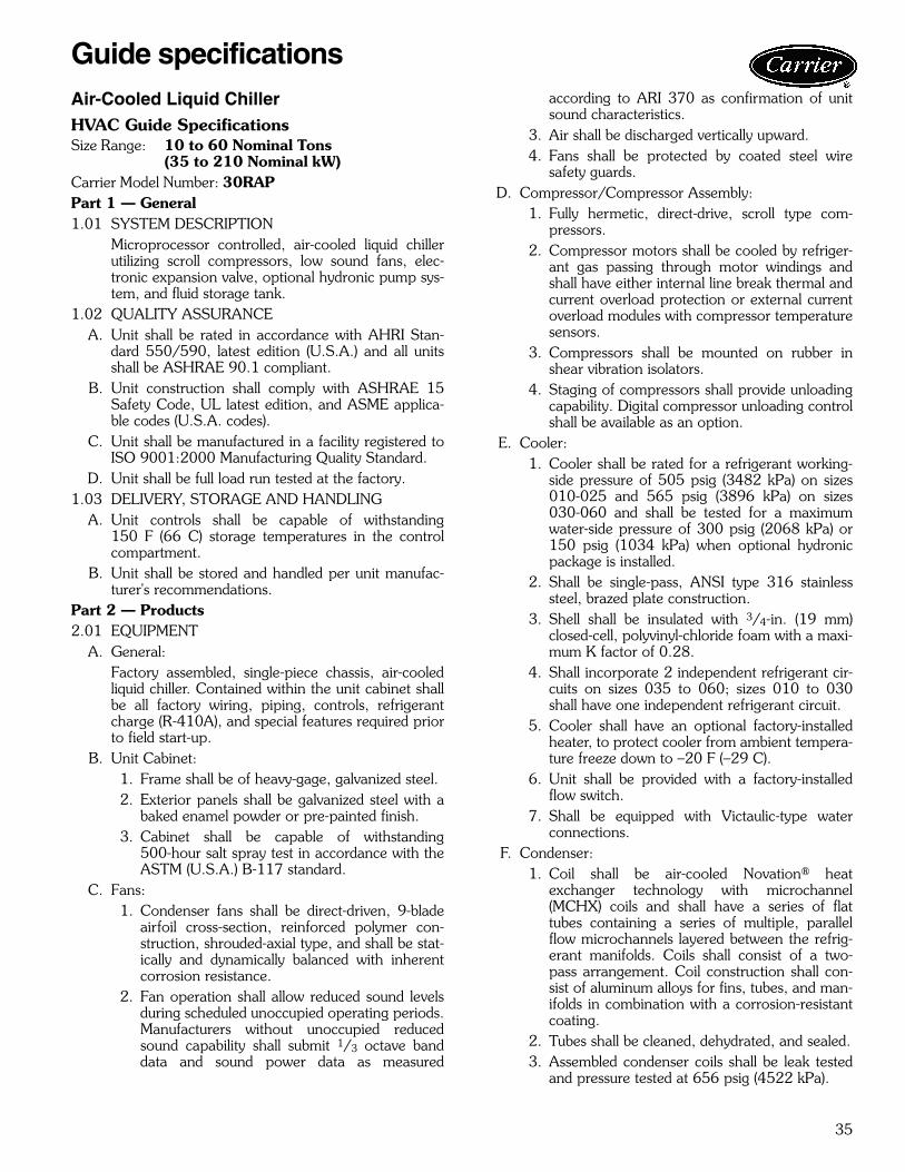
35
Air-Cooled Liquid ChillerHVAC Guide SpecificationsSize Range: 10 to 60 Nominal Tons
(35 to 210 Nominal kW)Carrier Model Number: 30RAPPart 1 — General1.01 SYSTEM DESCRIPTION
Microprocessor controlled, air-cooled liquid chillerutilizing scroll compressors, low sound fans, elec-tronic expansion valve, optional hydronic pump sys-tem, and fluid storage tank.
1.02 QUALITY ASSURANCEA. Unit shall be rated in accordance with AHRI Stan-
dard 550/590, latest edition (U.S.A.) and all unitsshall be ASHRAE 90.1 compliant.
B. Unit construction shall comply with ASHRAE 15Safety Code, UL latest edition, and ASME applica-ble codes (U.S.A. codes).
C. Unit shall be manufactured in a facility registered toISO 9001:2000 Manufacturing Quality Standard.
D. Unit shall be full load run tested at the factory.1.03 DELIVERY, STORAGE AND HANDLING
A. Unit controls shall be capable of withstanding150 F (66 C) storage temperatures in the controlcompartment.
B. Unit shall be stored and handled per unit manufac-turer's recommendations.
Part 2 — Products2.01 EQUIPMENT
A. General:Factory assembled, single-piece chassis, air-cooledliquid chiller. Contained within the unit cabinet shallbe all factory wiring, piping, controls, refrigerantcharge (R-410A), and special features required priorto field start-up.
B. Unit Cabinet:1. Frame shall be of heavy-gage, galvanized steel.2. Exterior panels shall be galvanized steel with a
baked enamel powder or pre-painted finish.3. Cabinet shall be capable of withstanding
500-hour salt spray test in accordance with theASTM (U.S.A.) B-117 standard.
C. Fans:1. Condenser fans shall be direct-driven, 9-blade
airfoil cross-section, reinforced polymer con-struction, shrouded-axial type, and shall be stat-ically and dynamically balanced with inherentcorrosion resistance.
2. Fan operation shall allow reduced sound levelsduring scheduled unoccupied operating periods.Manufacturers without unoccupied reducedsound capability shall submit 1/3 octave banddata and sound power data as measured
according to ARI 370 as confirmation of unitsound characteristics.
3. Air shall be discharged vertically upward.4. Fans shall be protected by coated steel wire
safety guards.D. Compressor/Compressor Assembly:
1. Fully hermetic, direct-drive, scroll type com-pressors.
2. Compressor motors shall be cooled by refriger-ant gas passing through motor windings andshall have either internal line break thermal andcurrent overload protection or external currentoverload modules with compressor temperaturesensors.
3. Compressors shall be mounted on rubber inshear vibration isolators.
4. Staging of compressors shall provide unloadingcapability. Digital compressor unloading controlshall be available as an option.
E. Cooler:1. Cooler shall be rated for a refrigerant working-
side pressure of 505 psig (3482 kPa) on sizes010-025 and 565 psig (3896 kPa) on sizes030-060 and shall be tested for a maximumwater-side pressure of 300 psig (2068 kPa) or150 psig (1034 kPa) when optional hydronicpackage is installed.
2. Shall be single-pass, ANSI type 316 stainlesssteel, brazed plate construction.
3. Shell shall be insulated with 3/4-in. (19 mm)closed-cell, polyvinyl-chloride foam with a maxi-mum K factor of 0.28.
4. Shall incorporate 2 independent refrigerant cir-cuits on sizes 035 to 060; sizes 010 to 030shall have one independent refrigerant circuit.
5. Cooler shall have an optional factory-installedheater, to protect cooler from ambient tempera-ture freeze down to –20 F (–29 C).
6. Unit shall be provided with a factory-installedflow switch.
7. Shall be equipped with Victaulic-type waterconnections.
F. Condenser:1. Coil shall be air-cooled Novation® heat
exchanger technology with microchannel(MCHX) coils and shall have a series of flattubes containing a series of multiple, parallelflow microchannels layered between the refrig-erant manifolds. Coils shall consist of a two-pass arrangement. Coil construction shall con-sist of aluminum alloys for fins, tubes, and man-ifolds in combination with a corrosion-resistantcoating.
2. Tubes shall be cleaned, dehydrated, and sealed.3. Assembled condenser coils shall be leak tested
and pressure tested at 656 psig (4522 kPa).
Guide specifications

36
G. Refrigeration Components:Refrigerant circuit components shall include filterdrier, moisture indicating sight glass, electronicexpansion device, and complete operating charge ofboth refrigerant R-410A and compressor oil.
H. Controls, Safeties, and Diagnostics:1. Unit controls shall include the following mini-
mum components:a. Microprocessor with non-volatile memory.
Battery backup system shall not be accepted.b. Single terminal block for power and
controls.c. Control transformer to serve all controllers,
relays, and control components.d. ON/OFF control switch.e. Replaceable solid-state controllers.f. Pressure sensors shall be installed to mea-
sure suction and discharge pressure for eachcircuit. Thermistors shall be installed to mea-sure cooler entering and leaving fluid tem-peratures, outdoor ambient temperature,and suction temperature. Provision for fieldinstallation of accessory sensor to measurecompressor return gas temperature.
2. Unit controls shall include the followingfunctions:a. Automatic circuit lead/lag for dual circuit
chillers.b. Hermetic scroll compressors are mainte-
nance free and protected by an auto-adaptivecontrol that minimizes compressor wear.
c. Capacity control based on leaving chilledfluid temperature and compensated by rateof change of return-fluid temperature withtemperature set point accuracy to 0.1° F(0.06° C).
d. Limiting the chilled fluid temperature pull-down rate at start-up to an adjustable rangeof 0.2° F to 2° F (0.11° C to 1.1° C) perminute to prevent excessive demand spikesat start-up.
e. Seven-day time schedule.f. Leaving chilled fluid temperature reset from
return fluid and outside air temperature.g. Chilled water pump start/stop control and
primary/standby sequencing to ensure equalpump run time.
h. Dual chiller control for parallel chiller appli-cations without addition of hardwaremodules and control panels (additionalthermistors and wells are required).
i. Timed maintenance scheduling to signalmaintenance activities for pumps, condensercoil cleanings, strainer maintenance anduser-defined maintenance activities.
j. Boiler enable signal to initiate system heat-ing mode.
k. Low ambient protection to energize coolerand hydronic system heaters.
l. Periodic pump start to ensure pump sealsare properly maintained during off-seasonperiods.
m. Single step demand limit control activated byremote contact closure.
n. Nighttime sound mode to reduce the soundof the machine by a user-defined schedule.
3. Diagnostics:a. The control panel shall include, as standard,
a scrolling marquee display capable of indi-cating the safety lockout condition bydisplaying a code for which an explanationmay be scrolled at the display.
b. Information included for display shall be:1) Compressor lockout.2) Loss of charge.3) Low fluid flow.4) Cooler freeze protection.5) Cooler set point.6) Chilled water reset parameters.7) Thermistor and transducer malfunction.8) Entering and leaving-fluid temperature.9) Compressor suction temperature.
10) Evaporator and condenser pressure.11) System refrigerant temperatures.12) Chiller run hours.13) Compressor run hours.14) Compressor number of starts.15) Low superheat.16) Time of day:
a) Display module, in conjunction withthe microprocessor, must also becapable of displaying the output(results) of a service test. Service testshall verify operation of everyswitch, thermistor, fan, and com-pressor before chiller is started.
b) Diagnostics shall include the abilityto review a list of the 20 most recentalarms with clear language descrip-tions of the alarm event. Display ofalarm codes without the ability forclear language descriptions shall beprohibited.
c) An alarm history buffer shall allowthe user to store no less than 20alarm events with clear languagedescriptions, time and date stampevent entry.
d) The chiller controller shall includemultiple connection ports for com-municating with the local equipmentnetwork, the Carrier Comfort Net-work® (CCN) system and access to
Guide specifications (cont)

37
chiller control functions from anypoint on the chiller.
e) The control system shall allow soft-ware upgrade without the need fornew hardware modules.
4. Safeties:a. Unit shall be equipped with thermistors and
all necessary components in conjunctionwith the control system to provide the unitwith the following protections:1) Loss of refrigerant charge.2) Reverse rotation.3) Low chilled fluid temperature.4) Thermal overload.5) High pressure.6) Electrical overload.7) Loss of phase.
b. Factory pump motors shall have externalovercurrent protection.
I. Operating Characteristics:1. Unit shall be capable of operating down to
–20 F (–29 C) on size 010 and 015 units, 45 F(7 C) on size 018-030 units, and 32 F (0° C) onsize 035-060 units as standard.
2. Unit shall be capable of starting and running atoutdoor ambient temperatures up to 120 F(50 C) for all sizes. Unit shall additionally beable to stay online when running with a 125 F(52 C) ambient temperature.
3. Unit shall be capable of starting up with 95 F(35 C) entering fluid temperature to the cooler.
J. Motors:Condenser-fan motors shall be totally enclosedsingle-speed, 3-phase type with permanently lubri-cated bearings and Class F insulation (except Motor-master® V control motors which shall be open typeand shall have Class B insulation).
K. Electrical Requirements:1. Unit/module primary electrical power supply
shall enter the unit at a single location.2. Unit shall operate on 3-phase power at the volt-
age shown in the equipment schedule.3. Control points shall be accessed through termi-
nal block.4. Unit shall be shipped with factory control and
power wiring installed.L. Chilled Water Circuit:
1. Chilled water circuit shall be rated for 300 psig(2068 kPa). Units with optional pump packageare rated for 150 psig (1034 kPa) workingpressure.
2. Solid-state flow monitor with integral relay shallbe factory installed and wired.
3. Brass body strainer with 40 mesh screen andball type blow down.
4. Optional hydronic package:a. Field pipe connections shall be copper Vict-
ualic type.b. Optional single or primary/stand-by opera-
tion pump systems. Dual pump systems shallhave a pump discharge check valve.
c. Pumps shall be single stage design, capableof being serviced without disturbing pipingconnections.1) Pump casing shall be of class 30 cast
iron.2) The impeller shall be of cast bronze,
closed type, dynamically balanced,keyed to the shaft and secured by lock-ing cap screw.
3) The hydronic kit will be provided witha flush line connection to ensure lubrica-tion at the seal face and allow forpositive venting of the seal chamber.
4) Pump shall be rated for 150 psig(1034 kPa) working pressure.
5) The pump case shall have gage tappingsat the suction and discharge nozzles andinclude drain ports.
6) Motors shall totally enclosed 3-phasetype with grease lubricated ball bearings.
7) Each pump shall be factory tested perHydraulic Institute Standards.
8) Pump motors shall be VFD (variable fre-quency drive) compatible.
d. Fluid expansion tank shall be factoryinstalled within the chiller cabinet insulates,pre-charged and rated for a maximum work-ing pressure of 150 psig (1034 kPa).
e. Water pressure taps (2) shall be factoryinstalled across the cooler and rated for150 psig (1034 kPa).
f. Balancing valve shall be factory installed toset flow gage ports shall be factory installedand rated for 300 psig (2068 kPa).
g. Hydronic assembly shall have factorysupplied electric freeze protection to –20 F(–29 C) when optional heaters are used.
h. Piping shall be type-L seamless coppertubing.
M. Special Features:Certain standard features are not applicablewhen the features designated by * are specified. Forassistance in amending the specifications, contactyour Carrier representative.
* 1. Low-Ambient Operation:Unit shall be capable of operating down to–20 F (–29 C) with the addition of the field orfactory-installed solid-state Motormaster® Vcontrol with condenser coil temperature sensor.In addition, adequate field-supplied antifreezewith suitable corrosion inhibitor protection shallbe field-installed in the evaporator circuit.
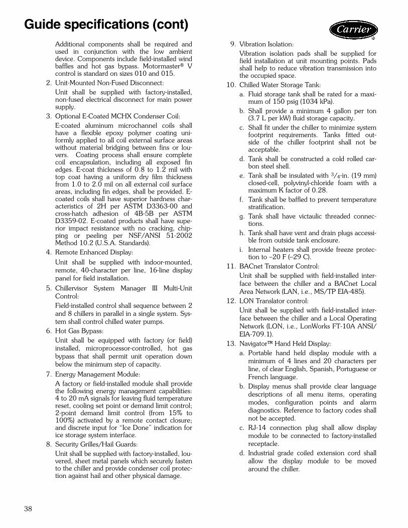
38
Additional components shall be required andused in conjunction with the low ambientdevice. Components include field-installed windbaffles and hot gas bypass. Motormaster® Vcontrol is standard on sizes 010 and 015.
2. Unit-Mounted Non-Fused Disconnect:Unit shall be supplied with factory-installed,non-fused electrical disconnect for main powersupply.
3. Optional E-Coated MCHX Condenser Coil:E-coated aluminum microchannel coils shallhave a flexible epoxy polymer coating uni-formly applied to all coil external surface areaswithout material bridging between fins or lou-vers. Coating process shall ensure completecoil encapsulation, including all exposed finedges. E-coat thickness of 0.8 to 1.2 mil withtop coat having a uniform dry film thicknessfrom 1.0 to 2.0 mil on all external coil surfaceareas, including fin edges, shall be provided. E-coated coils shall have superior hardness char-acteristics of 2H per ASTM D3363-00 andcross-hatch adhesion of 4B-5B per ASTMD3359-02. E-coated products shall have supe-rior impact resistance with no cracking, chip-ping or peeling per NSF/ANSI 51-2002Method 10.2 (U.S.A. Standards).
4. Remote Enhanced Display:Unit shall be supplied with indoor-mounted,remote, 40-character per line, 16-line displaypanel for field installation.
5. Chillervisor System Manager III Multi-UnitControl:Field-installed control shall sequence between 2and 8 chillers in parallel in a single system. Sys-tem shall control chilled water pumps.
6. Hot Gas Bypass:Unit shall be equipped with factory (or field)installed, microprocessor-controlled, hot gasbypass that shall permit unit operation downbelow the minimum step of capacity.
7. Energy Management Module:A factory or field-installed module shall providethe following energy management capabilities:4 to 20 mA signals for leaving fluid temperaturereset, cooling set point or demand limit control;2-point demand limit control (from 15% to100%) activated by a remote contact closure;and discrete input for “Ice Done” indication forice storage system interface.
8. Security Grilles/Hail Guards:Unit shall be supplied with factory-installed, lou-vered, sheet metal panels which securely fastento the chiller and provide condenser coil protec-tion against hail and other physical damage.
9. Vibration Isolation:Vibration isolation pads shall be supplied forfield installation at unit mounting points. Padsshall help to reduce vibration transmission intothe occupied space.
10. Chilled Water Storage Tank:a. Fluid storage tank shall be rated for a maxi-
mum of 150 psig (1034 kPa).b. Shall provide a minimum 4 gallon per ton
(3.7 L per kW) fluid storage capacity.c. Shall fit under the chiller to minimize system
footprint requirements. Tanks fitted out-side of the chiller footprint shall not beacceptable.
d. Tank shall be constructed a cold rolled car-bon steel shell.
e. Tank shall be insulated with 3/4-in. (19 mm)closed-cell, polyvinyl-chloride foam with amaximum K factor of 0.28.
f. Tank shall be baffled to prevent temperaturestratification.
g. Tank shall have victaulic threaded connec-tions.
h. Tank shall have vent and drain plugs accessi-ble from outside tank enclosure.
i. Internal heaters shall provide freeze protec-tion to –20 F (–29 C).
11. BACnet Translator Control:Unit shall be supplied with field-installed inter-face between the chiller and a BACnet LocalArea Network (LAN, i.e., MS/TP EIA-485).
12. LON Translator control:Unit shall be supplied with field-installed inter-face between the chiller and a Local OperatingNetwork (LON, i.e., LonWorks FT-10A ANSI/EIA-709.1).
13. Navigator™ Hand Held Display:a. Portable hand held display module with a
minimum of 4 lines and 20 characters perline, of clear English, Spanish, Portuguese orFrench language.
b. Display menus shall provide clear languagedescriptions of all menu items, operatingmodes, configuration points and alarmdiagnostics. Reference to factory codes shallnot be accepted.
c. RJ-14 connection plug shall allow displaymodule to be connected to factory-installedreceptacle.
d. Industrial grade coiled extension cord shallallow the display module to be movedaround the chiller.
Guide specifications (cont)

39
e. Magnets shall hold the display module toany sheet metal panel to allow hands-freeoperation.
f. Display module shall have NEMA 4xhousing suitable for use in outdoor environ-ments.
g. Display shall have back light and contrastadjustment for easy viewing in brightsunlight or night conditions.
h. Raised surface buttons with positive tactileresponse.
14. Touch Pilot™ Display:Unit shall be supplied with a remote mounttouch screen display for network attachment tothe chiller.
15. GFI Convenience Outlet:Shall be factory installed to provide the chillerwith a 4 amp GFI receptacle. The receptacleshall have independent fuse protection. Theconvenience outlet is a 115-v female recepta-cle.
16. Freeze Protection Cooler Heaters:Cooler heaters shall provide protection fromcooler freeze-up to –20 F (–29 C).
17. Value Sound Fans:Shall provide propeller-type fans for applica-tions that are not highly sound-sensitive.
18. Ultra-Low Sound:Shall provide an acoustic enclosure aroundeach compressor in conjunction with low-soundaero-acoustic fans to provide significant chillersound reduction.
19. High SCCR (Short Circuit Current Rating):The optional high SCCR (short circuit currentrating) device shall allow the chiller to tolerate a65 kA (208/230, 380 and 460-v units) or25 kA (575-v units) short circuit current for abrief period of time while protecting down-stream components. The high SCCR optionshall provide a higher level of protection thanthe standard unit.
20. Digital Compressor Option:Shall provide a factory-installed digital compres-sor to provide incremental steps for tighter tem-perature control (not available on size 018units).

Manufacturer reserves the right to discontinue, or change at any time, specifications or designs without notice and without incurring obligations.Pg 40 Catalog No. 04-52300018-01 Printed in U.S.A. Form 30RAP-1APD
Replaces: NewBook 9Section 9b
Carrier Corporation • Syracuse, New York 13221 9-09
Related Documents