Instructions-Parts List STAINLESS STEEL 2-Gallon Pressure Tanks 308370W EN Industrial grade pressure tanks used to supply, agitate, and pressurize finishing liquids. For professional use only. Maximum Air Inlet Pressure 100 psi (0.7 MPa, 7 bar) Maximum Air Inlet Pressure: 100 psi (0.7 MPa, 7 bar) Maximum Working Fluid Pressure Low-Pressure Regulated Tank 15 psi (0.1 MPa, 1 bar) (for HVLP or low-pressure, fine-adjustment applications) High-Pressure Regulated Tank 100 psi (0.7 MPa, 7 bar) See page 2 for model information, including approvals. Important Safety Instructions Read all warnings and instructions in this manual. Save these instructions. Low-Pressure Tank Low-Pressure Tank with Agitator High-Pressure Tank High-Pressure Tank with Agitator 3092a 3094b 3096 ASME

Welcome message from author
This document is posted to help you gain knowledge. Please leave a comment to let me know what you think about it! Share it to your friends and learn new things together.
Transcript

Instructions-Parts List
STAINLESS STEEL
2-Gallon Pressure Tanks308370W
EN
Industrial grade pressure tanks used to supply, agitate, and pressurize finishing liquids. For professional use only. Maximum Air Inlet Pressure 100 psi (0.7 MPa, 7 bar)
Maximum Air Inlet Pressure: 100 psi (0.7 MPa, 7 bar)Maximum Working Fluid Pressure
Low-Pressure Regulated Tank 15 psi (0.1 MPa, 1 bar)(for HVLP or low-pressure, fine-adjustment applications)
High-Pressure Regulated Tank 100 psi (0.7 MPa, 7 bar)
See page 2 for model information, including approvals.
Important Safety InstructionsRead all warnings and instructions in this manual. Save these instructions.
Low-Pressure Tank
Low-Pressure Tankwith Agitator
High-Pressure Tank
High-Pressure Tankwith Agitator
3092a
3094b
3096
ASME

Table of Contents
2 308370W
Table of ContentsTable of Contents . . . . . . . . . . . . . . . . . . . . . . . . . . 2Models . . . . . . . . . . . . . . . . . . . . . . . . . . . . . . . . . . . 2Warnings . . . . . . . . . . . . . . . . . . . . . . . . . . . . . . . . . 3Typical System . . . . . . . . . . . . . . . . . . . . . . . . . . . . 5Installation . . . . . . . . . . . . . . . . . . . . . . . . . . . . . . . . 6
Pressure Relief Procedure . . . . . . . . . . . . . . . . . 6Grounding . . . . . . . . . . . . . . . . . . . . . . . . . . . . . 6Connecting Hoses . . . . . . . . . . . . . . . . . . . . . . . 6Recommended Hose Sizes (general purpose) . . 7Installing An Agitator . . . . . . . . . . . . . . . . . . . . . 7
Operation . . . . . . . . . . . . . . . . . . . . . . . . . . . . . . . . . 8Preparing the Fluid . . . . . . . . . . . . . . . . . . . . . . . 8Filling the Tank . . . . . . . . . . . . . . . . . . . . . . . . . . 8Operating the Pressure Tank . . . . . . . . . . . . . . . 8Safety Relief Valve . . . . . . . . . . . . . . . . . . . . . . . 8
Maintenance . . . . . . . . . . . . . . . . . . . . . . . . . . . . . . . 9Cleaning the Tank . . . . . . . . . . . . . . . . . . . . . . . 9Maintaining Air Regulator . . . . . . . . . . . . . . . . . . 9Maintaining the Agitator Air Motor . . . . . . . . . . . 9
Parts . . . . . . . . . . . . . . . . . . . . . . . . . . . . . . . . . . . . 11Agitator . . . . . . . . . . . . . . . . . . . . . . . . . . . . . . . 11Low-Pressure Stainless Steel Tank . . . . . . . . . . 13Low Pressure Stainless Steel Tank with Agitator 15High-Pressure Stainless Steel Tank . . . . . . . . . 17High Pressure Stainless Steel Tank with Agitator 19
Accessories . . . . . . . . . . . . . . . . . . . . . . . . . . . . . . 21Dimensions . . . . . . . . . . . . . . . . . . . . . . . . . . . . . . . 22Technical Specifications . . . . . . . . . . . . . . . . . . . . 23California Proposition 65 . . . . . . . . . . . . . . . . . . . 23Graco Standard Warranty . . . . . . . . . . . . . . . . . . . 24
Models
All pressure tanks listed are CE approved to the Pressure Equipment Directive (Category II). Items marked * also are
approved to
Pressure Tank Regulation Series B Pressure Tank Series B Pressure Tank with Agitator Series B
Low Pressure 236155 236156*
HIgh Pressure 236157 236158*
2575 II 1/2 G T6ITS03ATEX11251

Warnings
308370W 3
WarningsThe following warnings are for the setup, use, grounding, maintenance, and repair of this equipment. The exclama-tion point symbol alerts you to a general warning and the hazard symbols refer to procedure-specific risks. When these symbols appear in the body of this manual or on warning labels, refer back to these Warnings. Product-specific hazard symbols and warnings not covered in this section may appear throughout the body of this manual where applicable.
WARNINGWARNINGWARNINGWARNINGEQUIPMENT MISUSE HAZARDMisuse can cause death or serious injury.• Do not operate the unit when fatigued or under the influence of drugs or alcohol.• Do not exceed the maximum working pressure or temperature rating of the lowest rated system com-
ponent. See Technical Specifications in all equipment manuals.• Use fluids and solvents that are compatible with equipment wetted parts. See ‡ in all equipment man-
uals. Read fluid and solvent manufacturer’s warnings. For complete information about your material, request MSDS from distributor or retailer.
• Do not leave the work area while equipment is energized or under pressure.• Turn off all equipment and follow the Pressure Relief Procedure when equipment is not in use.• Check equipment daily. Repair or replace worn or damaged parts immediately with genuine manufac-
turer’s replacement parts only.• Do not alter or modify equipment. Alterations or modifications may void agency approvals and create
safety hazards.• Make sure all equipment is rated and approved for the environment in which you are using it.• Use equipment only for its intended purpose. Call your distributor for information.• Route hoses and cables away from traffic areas, sharp edges, moving parts, and hot surfaces.• Do not kink or over bend hoses or use hoses to pull equipment.• Keep children and animals away from work area.• Comply with all applicable safety regulations.
FIRE AND EXPLOSION HAZARD Flammable fumes, such as solvent and paint fumes, in work area can ignite or explode. To help prevent fire and explosion:• Use equipment only in well ventilated area.• Eliminate all ignition sources; such as pilot lights, cigarettes, portable electric lamps, and plastic drop
cloths (potential static arc). • Keep work area free of debris, including solvent, rags and gasoline.• Do not plug or unplug power cords, or turn power or light switches on or off when flammable fumes are
present.• Ground all equipment in the work area. See Grounding instructions.• Use only grounded hoses.• Hold gun firmly to side of grounded pail when triggering into pail. Do not use pail liners unless they are
antistatic or conductive.• Stop operation immediately if static sparking occurs or you feel a shock. Do not use equipment until
you identify and correct the problem.• Keep a working fire extinguisher in the work area.

Warnings
4 308370W
MOVING PARTS HAZARDMoving parts can pinch, cut or amputate fingers and other body parts.• Keep clear of moving parts.• Do not operate equipment with protective guards or covers removed.• Pressurized equipment can start without warning. Before checking, moving, or servicing equipment,
follow the Pressure Relief Procedure and disconnect all power sources.
TOXIC FLUID OR FUMES HAZARDToxic fluids or fumes can cause serious injury or death if splashed in the eyes or on skin, inhaled, or swal-lowed.• Read MSDSs to know the specific hazards of the fluids you are using.• Store hazardous fluid in approved containers, and dispose of it according to applicable guidelines.
WARNINGWARNINGWARNINGWARNING

Typical System
308370W 5
Typical SystemReference numbers and letters in parentheses in the text refer to references in the illustrations and the parts draw-ings.
See page 21 for Accessories that are available from Graco. Be sure that all accessories are properly sized to with-stand the pressures in the system.
FIG. 1
5
H
A
15
C
G
D
F
B
K
J
E
113
A Air supply hoseB Main air supplyC Ground clamp & wire (Required)D Atomizing air hoseE Fluid hoseF Air spray gunG Air regulator & filter:
1/4-18 npt outlets (2) 1/2-14 npt inlet
H Agitator air hoseJ Tank air regulatorK Fluid outlet ball valve; 3/8-18 npsm(m)x3/8-18 npt(m)5 Pipe plug12 Safety valve15 Air inlet ball valve; 1/4-18 npt(m)113 Needle valve
12

Installation
6 308370W
Installation
Pressure Relief Procedure
1. Shut off the air supply to the tank by closing the air inlet valve (15). Refer to FIG. 2.
2. Open the drain cock fitting (7) by turning it counter-clockwise. Refer to FIG. 3.
3. Wait until there is no air escaping through the drain cock fitting before removing the cover or opening the fill port.
4. Leave the drain cock fitting (7) open until you have reinstalled the cover or fill port.
NOTE: Torque c-clamps to 8-10 ft-lbs, approximately 1/2 to 1 turn past hand tight.
Grounding Check your local code for detailed grounding instruc-tions for your area and type of equipment. Be sure to ground thepressure tank by connecting one end of a 12 awg (1.5 mm2) minimum ground wire to the pressure tank and the other end of the wire to a true earth ground.
Connecting Hoses See FIG. 2 Connect an air supply hose to the 1/4 npt(m) air inlet valve (15) and your air supply. Install an air regu-lator and filter (G) upstream from the air inlet valve to remove dirt and moisture from your air supply. See Accessories on page 21. Connect a fluid hose (E) between the 3/8 npsm(m) outlet valve (K) and the fluid inlet of your spray gun.
To add a second air regulator to control air to a spray gun, see Accessories on page 21 for Gun Air Regulator Kit. The second air regulator installs in place of pipe plug (5). See FIG. 3.
Always maintain a minimum of 1 in. clearance between rotating agitator parts and container to prevent sparks from contact.
The pressure tanks remain pressurized until pressure is manually relieved. To reduce the risk of serious injury from pressurized fluid or accidental spray from the gun, always follow this procedure to relieve pressure in the tank at the following times:
• Before you check or service any part of the spray system
• Before you loosen or remove the pressure tank cover or fill port
• Whenever you stop spraying
FIG. 2
E
FIG. 3
265
7
20
17
11
4
14
3091a

Installation
308370W 7
Recommended Hose Sizes (general purpose)
Installing An Agitator 1. Follow the Pressure Relief Procedure on page 5.
2. Remove the cover (26) from the tank. Remove the hex jam nut (14) from bottom of the cover. Remove the o-ring (20), adapter plug (17), and handle (4). Keep the hex jam nut (14). See FIG. 3.
3. Fit the gasket (217) under the coupling housing (112), and place the motor shaft (111) through cover’s center hole. Screw the hex jam nut (14) onto the coupling housing, and torque it to 50 ft-lb (68 N-m). See FIG. 4.
4. Position the shaft coupling (218) over the motor shaft (111), and tighten the top setscrew into shaft. Insert the shaft (220) into the shaft coupling, and tighten the lower setscrew into the shaft. Thread on the nut (221), mixer blade (222), washer (223), and nut (224). See FIG. 4.
5. Connect the elbow (105) to the manifold (10) in place of plug. Connect the agitator hose (114) to the elbow (105). See FIG. 4.
Fluid AirFor runs of: Use: For runs of: Use:0 to 35 ft (0 to 11 m)
3/8” ID 0 to 50 ft (0 to 15 m)
5/16” ID
35 to 100 ft (11 to 30 m)
1/2” ID 50 to 100 ft (15 to 30 m)
3/8” ID
100 to 200 ft (30 to 61 m)
3/4” ID 100 ft+ (30 m+)
1/2” ID
This is a pressurized tank. Always follow the Pressure Relief Procedure on page 5 before opening the tank cover or fill port. This reduces the risk of serious injury, including splashing in the eyes or on the skin, or injury from moving parts. These injuries can result if the tank pressure is not fully relieved.
FIG. 4
10
220
224223
222
221
105
113
114
112
111
217218
14
3093b
Operation
8 308370W
Operation
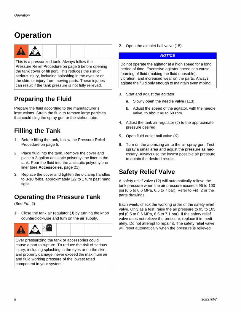
Preparing the Fluid Prepare the fluid according to the manufacturer’s instructions. Strain the fluid to remove large particles that could clog the spray gun or the siphon tube.
Filling the Tank 1. Before filling the tank, follow the Pressure Relief
Procedure on page 5.
2. Place fluid into the tank. Remove the cover and place a 2-gallon antistatic polyethylene liner in the tank. Pour the fluid into the antistatic polyethylene liner (see Accessories, page 21).
3. Replace the cover and tighten the c-clamp handles to 8-10 ft-lbs, approximately 1/2 to 1 turn past hand tight.
Operating the Pressure Tank (See FIG. 2)
1. Close the tank air regulator (J) by turning the knob counterclockwise and turn on the air supply.
2. Open the air inlet ball valve (15).
3. Start and adjust the agitator:
a. Slowly open the needle valve (113).
b. Adjust the speed of the agitator, with the needle valve, to about 40 to 60 rpm.
4. Adjust the tank air regulator (J) to the approximate pressure desired.
5. Open fluid outlet ball valve (K).
6. Turn on the atomizing air to the air spray gun. Test spray a small area and adjust the pressure as nec-essary. Always use the lowest possible air pressure to obtain the desired results.
Safety Relief Valve A safety relief valve (12) will automatically relieve the tank pressure when the air pressure exceeds 95 to 100 psi (0.5 to 0.6 MPa, 6.5 to 7 bar). Refer to FIG. 2 or the parts drawings.
Each week, check the working order of the safety relief valve. Only as a test, raise the air pressure to 95 to 105 psi (0.5 to 0.6 MPa, 6.5 to 7.1 bar). If the safety relief valve does not relieve the pressure, replace it immedi-ately. Do not attempt to repair it. The safety relief valve will reset automatically when the pressure is relieved.
This is a pressurized tank. Always follow the Pressure Relief Procedure on page 5 before opening the tank cover or fill port. This reduces the risk of serious injury, including splashing in the eyes or on the skin, or injury from moving parts. These injuries can result if the tank pressure is not fully relieved.
Over pressurizing the tank or accessories could cause a part to rupture. To reduce the risk of serious injury, including splashing in the eyes or on the skin, and property damage, never exceed the maximum air and fluid working pressure of the lowest rated component in your system.
NOTICE
Do not operate the agitator at a high speed for a long period of time. Excessive agitator speed can cause foaming of fluid (making the fluid unusable), vibration, and increased wear on the parts. Always agitate the fluid only enough to maintain even mixing.

Maintenance
308370W 9
Maintenance
Cleaning the Tank 1. First follow the Pressure Relief Procedure on page
5.
2. Follow the procedure below to force the fluid back through the hose and into the tank:
a. Loosen the spray gun air cap retaining ring about two turns.
b. Hold a rag over the air cap, and trigger the gun for a few seconds until the fluid is forced back into the tank.
3. Remove the tank cover.
4. Empty the fluid from the tank and pour a suitable amount of solvent into it.
5. Replace the tank cover and tighten the c-clamps to 8-10 ft-lbs, approximately 1/2 to 1 turn past hand tight.
6. Close the drain cock fitting (7).
7. Turn on the air supply.
8. Hold a metal part of the gun against a grounded metal container, and trigger the gun into the con-tainer until clean solvent comes from the gun.
9. Remove the solvent from the system and wipe the inside of the tank and the rest of the equipment clean with a solvent-dampened rag.
Maintaining Air Regulator See separate instruction manual 307204 for care and maintenance of air regulator.
Maintaining the Agitator Air Motor (See FIG. 5)
Lubricate agitator motor as follows whenever it will be shut down for more than 8 hours: Remove the air motor cap, and apply 15 to 20 drops of oil in the oiler. Replace the cap, and run agitator for about 1/2 minute.
This is a pressurized tank. Always follow the Pressure Relief Procedure on page 5 before opening the tank cover or fill port. This reduces the risk of serious injury, including splashing in the eyes or on the skin, or injury from moving parts. These injuries can result if the tank pressure is not fully relieved.
NOTICE
Be sure that the solvent you use is compatible with the fluid being sprayed. Read Equipment Misuse Hazard on page 3.
FIG. 5
111
3099a
103
110
113
104
107
112
109108

Maintenance
10 308370W
If air motor doesn’t run smoothly and easily, flush it out by removing the muffler (110) and filling the muffler cav-ity with kerosene. Screw muffler back in. Soak for about 10 minutes, then run agitator slowly until all kerosene is blown out. Repeat process if motor still doesn’t run smoothly.
If air motor still doesn’t operate properly, contact an authorized Graco service representative. Do not attempt to service it yourself.
If air leaks around the motor shaft (111) due to wear, the shaft may be inverted. Loosen the setscrews (107) around the top of the coupler housing (112) and remove the motor (104). Push the motor shaft up through the bottom of the housing. Loosen the bottom setscrew of the flexible coupling (103) and remove the motor shaft. Turn the motor shaft around, reposition the flexible cou-pling and tighten setscrew. Fit the seal (109) and bear-ing (108) into housing, then push the shaft and coupling through the housing. Reposition housing onto motor and tighten screws. See Agitator Parts Drawing on page 11.
To reduce risk of serious bodily injury, including splash-ing kerosene in the eyes or on skin, keep face and body away from exhaust while flushing.

Parts
308370W 11
Parts
AgitatorModel 236859
103
3099a
102
114
110106
105
111
113
104
115
116
101
107
112
108
109
217
218
219
220
221
222
223
224
100
200

Parts
12 308370W
Agitator - Parts ListRef. No. Part No. Description Qty.
100 236097 MOTOR, assy, agitator; 2-gal. 1101 100133 WASHER, lock; 3/8 2102 100575 SCREW, cap, hex, hd;
3/8-16 unc-2a2
103 100828 COUPLING, flexible 1104 101140 MOTOR, rotary, air 1105 112307 ELBOW, street, 90°
1/8-27 npt(f) x 1/4-18 npt(m)1
106 104391 BEARING, sleeve, plain 1107 102387 SETSCREW, hex hd socket
10-32 unf-3a3
108 105286 SEAL, shaft, spring-loaded 1109 105285 BEARING, flange 1110 156969 MUFFLER, 1/4 npt(m) 1111 188883 SHAFT, motor; 2-gal. 1112 188882 HOUSING, coupling; 2-gal. 1
113 206264 VALVE, needle 1114 164724 HOSE, cpld; 1/8 npt(m) l
swivel one end; 1/4 ID; 10 in (242 mm) long
1
115 175074 HANDLE 1116 176184 GRIP, handle 1200 236860 KIT, accessory, 2-gal. 1217 196309 GASKET, LDPE foam 1218 185460 COUPLING, shaft; 1219 110272 SETSCREW, socket,
hd cup pt; 1/4 npt x 3/81
220 188892 SHAFT, 2-gal.; 3/8-16 unc-2a 1221 112309 NUT, hex, jam; sst 1222 110275 BLADE, mixer; polypropylene 1223 110273 WASHER, lock 1224 110271 NUT, hex, cap; 3/8-16 npt 1
Ref. No. Part No. Description Qty.

Parts
308370W 13
Low-Pressure Stainless Steel TankModel 236155
3091a27
24
35*
16
30
26
6
2521
3
32
28
14
23
13
20
17
11
4
2
29a
29
9
31
1
15
7
18
10 3
34
512
Tank assembly includes tank (24), gasket (25), cover (26), and plug (27).
*Torque to 8-10 ft-lbs

Parts
14 308370W
Low-Pressure Stainless Steel Tank - Parts ListRef. No. Part No. Description Qty.
1 110476 ADAPTER, union, straight swivel; 3/8 npt(m) to 1/4 npsm(f)
2
2 176184 GRIP, handle 13 100840 ELBOW, street; 1/4-18 npt(m x f) 24 175075 HANDLE 15 104813 PLUG, pipe; 3/8-18 npt 16 112306 PLUG, pipe; 3/8-18 npt; sst 17 101759 FITTING, drain cock 19 112307 ELBOW, street, 90°
1/8-27 npt(f) x 1/8-27 npt(m)1
10 189016 MANIFOLD, air inlet; 3/8-18 npt;1/4-18 npt
1
11 102300 NUT, jam, hex; 9/16-18 112 103347 VALVE, safety; 1/4-18 npt(m);
100 psi (0.7 MPa, 7 bar)1
13 110756 ELBOW, street, 90°3/8 npt x 3/8 npt; sst
1
14 188784 NUT, jam, hex; 1-1/2-12-unf-2b; 115 208390 VALVE, ball; 1/4-18 npt(m);
See 307068 for parts .1
16 156849 NIPPLE, pipe; 3/8-18 npt 117 188881 PLUG, tapped; 118 100030 BUSHING;
1/8-27 npt(f) x 1/4-18 npt(m) 1
20 165053 O-RING, packing; PTFE 121 185531 TUBE, siphon; sst 122 175078 LABEL, Warning (not shown) 123 236439 VALVE, ball; sst;
3/8-18 npsm(m) x 3/8-18 npt(m),See 307068 for parts .
1
24 236086 TANK; 2-gal. size; sst, 125 117572 GASKET; Santoprene® 1
26 COVER, tank; sst 127 PLUG, bottom; 3/4-14 npt 128 110444 GAUGE, pressure, air 0 to 15 psi
(0 to 0.1 MPa, 0 to 1 bar)1
29 111501 REGULATOR; 0 to 15 psi(0 to 0.1 MPa, 0 to 1 bar)
1
29a PLUG, 1/8-27 npt 130 110475 TEE, street; 1/8 npt 131 164724 HOSE, coupled; 400 wpr; 1/8-27
npt(m)1
32 151519 NIPPLE, reducing; 1/4-1/8 npt 134 100139 PLUG, pipe, headless; 1/8-27 npt 235† T-HANDLE 436‡ LINER, antistatic, polyethylene;
(not shown)1
Keep these spare parts on hand to reduce down time
† A C-clamp replacement Kit is available. It includes the T-handle, C-clamp, pin, and cotter pin. Order part no. 111380.
‡ To purchase a box of antistatic polyethylene lin-ers, see Accessories on page 21.
NOTE: The 307 numbers in the descriptions refer to separate instruction manuals.
Ref. No. Part No. Description Qty.

Parts
308370W 15
Low Pressure Stainless Steel Tank with Agitator Model 236156
3093b29
26
37*
27
6
28
21
14
39
25
13
33a
33
9
35
32
36
17
3
15
512
3
16
10
1834
Tank assembly includes tank (26), gasket (27), cover (28), and plug (29).
See page 11 for agitator parts
*Torque to 8-10 ft-lbs

Parts
16 308370W
Low Pressure Stainless Steel Tank with Agitator - Parts ListRef. No. Part No. Description Qty.
1 110476 ADAPTER, union, straight swivel; 3/8 npt(m) to 1/4 npsm(f)
1
3 100840 ELBOW, street; 1/4-18 npt(m x f) 25 104813 PLUG, pipe; 3/8-18 npt 16 112306 PLUG, pipe; 3/8-18 npt; sst 17 101759 FITTING, drain cock 19 112307 ELBOW, street, 90°
1/8-27 npt(f) x 1/8-27 npt(m)1
10 189016 MANIFOLD, air inlet; 3/8-18 npt;1/4-18 npt
1
12 103347 VALVE, safety; 1/4-18 npt(m);100 psi (0.7 MPa, 7 bar)
1
13 110756 ELBOW, street, 90°3/8 npt x 3/8 npt; sst
1
14 188784 NUT, jam, hex; 1-1/2-12-unf-2b; 115 208390 VALVE, ball; 1/4-18 npt(m);
See 307068 for parts .1
16 156849 NIPPLE, pipe; 3/8-18 npt 118 100030 BUSHING;
1/8-27 npt(f) x 1/4-18 npt(m) 1
21 185531 TUBE, siphon; sst 123 175078 LABEL, Warning (Not Shown) 125 236439 VALVE, ball; sst;
3/8-18 npsm(m)x3/8-18 npt(m),See 307068 for parts
1
26 236086 TANK; 2-gal. size; sst 127 117572 GASKET, Santoprene® 1
28 COVER, tank; sst 129 PLUG, bottom 3/4-14 npt 132 110444 GAUGE, pressure, air; 0 to 15 psi
(0 to 0.1 MPa, 0 to 1 bar)1
33 111501 REGULATOR; 0 to 15 psi(0 to 0.1 MPa, 0 to 1 bar)
1
33a PLUG, 1/8-27 npt 134 110475 TEE, street; 1/8 npt 135 164724 HOSE, coupled; 400 wpr; 1/8-27
npt(m)1
36 151519 NIPPLE, reducing; 1/4-1/8 npt 137† T-HANDLE 438‡ LINER, antistatic, polyethylene;
(not shown)1
39 222011 CLAMP, grounding 1
Keep these spare parts on hand to reduce down time
† A C-clamp replacement Kit is available. It includes the T-handle, C-clamp, pin, and cotter pin. Order part no. 111380.
‡ To purchase a box of antistatic polyethylene lin-ers, see Accessories on page 21.
NOTE: The 307 numbers in the descriptions refer to separate instruction manuals.
Ref. No. Part No. Description Qty.

Parts
308370W 17
High-Pressure Stainless Steel TankModel 236157
27
Tank assembly includes tank (24), gasket (25), cover (26), and plug (27).
24
36*
25
6
26
21
14
23
13
20
17
11
4
2
28
32
1
7
3
3
12
16
5
35
15
10
1830
31
9
29
33
*Torque to 8-10 ft-lbs

Parts
18 308370W
High-Pressure Stainless Steel Tank - Parts ListRef. No. Part No. Description Qty.
1 155665 UNION, adapter;3/8 npt(m) to 3/8 npsm(f)
1
2 176184 GRIP, handle 13 100840 ELBOW, street; 1/4-18 npt(m x f) 24 175075 HANDLE 15 104813 PLUG, pipe; 3/8-18 npt 16 112306 PLUG, pipe; 3/8-18 npt; sst 17 101759 FITTING, drain cock 19 112538 ELBOW, street, 90°
1/8-27 npt(f) x 1/4-18 npt(m)1
10 189016 MANIFOLD, air inlet; 3/8-18 npt;1/4-18 npt
1
11 102300 NUT, jam, hex; 9/16-18 112 103347 VALVE, safety; 1/4-18 npt(m);
100 psi (0.7 MPa, 7 bar)1
13 110756 ELBOW, street, 90°3/8 npt x 3/8 npt; sst
1
14 188784 NUT, jam, hex; 1-1/2-12-unf-2b; 115 208390 VALVE, ball; 1/4-18 npt(m);
See 307068 for parts .1
16 156849 NIPPLE, pipe; 3/8-18 npt 117 188881 PLUG, tapped; 118 100030 BUSHING;
1/8-27 npt(f) x 1/4-18 npt(m) 1
20 165053 O-RING, packing; PTFE 121 185531 TUBE, siphon; sst 122 175078 LABEL, Warning (Not Shown) 123 236439 VALVE, ball; sst;
3/8-18 npsm(m)x3/8-18 npt(m),See 307068 for parts
1
24 236086 TANK; 2-gal. size; sst 125 117572 GASKET, Santoprene® 1
26 COVER, tank; sst 127 PLUG, bottom 3/4-14 npt 128 160430 GAUGE, pressure, air;
0 to 100 psi(0 to 0.7 MPa, 0 to 7bar)
1
29 104267 REGULATOR; 2 to 125 psi(0.01 to 0.8 MPa, 0.1 to 9 bar)
1
30 110475 TEE, street; 1/8 npt 131 164724 HOSE, coupled; 400 wpr; 1/8-27
npt(m)1
32 159239 NIPPLE, pipe reducing; 1/2-3/8 npt
1
33 100361 PLUG, pipe, headless;1/2-14 npt(f)
1
35 100139 PLUG, pipe, headless; 1/8-27 npt 136† T-HANDLE 437‡ LINER, antistatic, polyethylene;
(not shown)1
Keep these spare parts on hand to reduce down time
† A C-clamp replacement Kit is available. It includes the T-handle, C-clamp, pin, and cotter pin. Order part no. 111380.
‡ To purchase a box of antistatic polyethylene lin-ers, see Accessories on page 21.
NOTE: The 307 numbers in the descriptions refer to separate instruction manuals.
Ref. No. Part No. Description Qty.

Parts
308370W 19
High Pressure Stainless Steel Tank with AgitatorModel 236158
29
Tank assembly includes tank (26), gasket (27), cover (28), and plug (29).
26
38*27
6
28
22
14
25
13
33
36
1
7
3
3
12
16
5
15
10
1834
35
9
32
37
40
See page 11 for agitator parts
*Torque to 8-10 ft-lbs

Parts
20 308370W
High Pressure Stainless Steel Tank with Agitator - Parts List
Ref. No. Part No. Description Qty.
1 155665 UNION, adapter;3/8 npt(m) to 3/8 npsm(f)
1
3 100840 ELBOW, street; 1/4-18 npt(m x f) 25 104813 PLUG, pipe; 3/8-18 npt 16 112306 PLUG, pipe; 3/8-18 npt; sst 17 101759 FITTING, drain cock 19 112538 ELBOW, street, 90°
1/8-27 npt(f) x 1/4-18 npt(m)1
10 189016 MANIFOLD, air inlet; 3/8-18 npt;1/4-18 npt
1
12 103347 VALVE, safety; 1/4-18 npt(m);100 psi (0.7 MPa, 7 bar)
1
13 110756 ELBOW, street, 90°3/8 npt x 3/8 npt; sst
1
14 188784 NUT, jam, hex; 1-1/2-12-unf-2b; 115 208390 VALVE, ball; 1/4-18 npt(m);
See 307068 for parts .1
16 156849 NIPPLE, pipe; 3/8-18 npt 118 100030 BUSHING;
1/8-27 npt(f) x 1/4-18 npt(m) 1
20 175078 LABEL, Warning (Not Shown) 122 185531 TUBE, siphon; sst 125 236439 VALVE, ball; sst;
3/8-18 npsm(m)x3/8-18 npt(m),See 307068 for parts
1
26 236086 TANK; 2-gal. size; sst 127 117572 GASKET, Santoprene® 1
28 COVER, tank; sst 1
29 PLUG, bottom 3/4-14 npt 132 104267 REGULATOR; 2 to 125 psi
(0.01 to 0.8 MPa, 0.1 to 9 bar)1
33 160430 GAUGE, pressure, air; 0 to 100 psi(0 to 0.7 MPa, 0 to 7bar)
1
34 110475 TEE, street; 2x1/8-27 npt (f) 135 164724 HOSE, coupled; 400 wpr;
1/8-27 npt(m)1
36 159239 NIPPLE, pipe reducing; 1/2-3/8 npt
1
37 100361 PLUG, pipe, headless;1/2-14 npt(f)
1
38† T-HANDLE 439‡ LINER, antistatic, polyethylene;
(not shown)1
40 222011 CLAMP, grounding 1
Keep these spare parts on hand to reduce down time
† A C-clamp replacement Kit is available. It includes the T-handle, C-clamp, pin, and cotter pin. Order part no. 111380.
‡ To purchase a box of antistatic polyethylene lin-ers, see Accessories on page 21.
NOTE: The 307 numbers in the descriptions refer to separate instruction manuals.
Ref. No. Part No. Description Qty.

Accessories
308370W 21
AccessoriesGun Regulator Kit 235042100 psi (0.7 MPa, 7 bar) Working Pressure
Kit to add a second air regulator, used to supply atomiz-ing air to a spray gun from the pressure pot.
Strainer 202271300 psi (2.1 MPa, 21 bar) Maximum Working Pressure
Install at the tank air inlet to remove dirt and moisture from the air supply, or at the tank fluid outlet to remove particles from the paint which could clog the spray gun nozzle.
Buna-N Air Supply Hose 200 psi (1.4 MPa, 14 bar) Maximum Working Pressure
5/16” ID; cpld 1/4 npsm(f) swivel 210866 15 ft (4.6 m) long 210867 25 ft (7.6 m) long
Low-Pressure Regulator Conversion Kit 235041 15 psi (0.1 MPa, 1 bar) Working Pressure. 0 to 15 psi (0 to 0.1 MPa, 0 to 1 bar) regulated pressure range
To convert to a low-pressure regulator assembly.
High-Pressure Regulator Conversion Kit 236680 100 psi (0.7 MPa, 7 bar) Working Pressure. 0 to 100 psi (0 to 0.7 MPa, 0 to 7 bar) regulated pressure range
Stainless Steel Mixer Blade186522 304 stainless steel
Nylon Fluid Supply Hose 300 psi (2.1 MPa, 21 bar) Maximum Working Pressure
3/8” ID; cpld 3/8 npsm(fbe) swivel; neoprene cover 205160 15 ft (4.6 m) long 205142 25 ft (7.6 m) long 205143 50 ft (15.2 m) long
Bottom Outlet Kit 236676 For bottom outlet fluid feeding.
C-clamp Replacement Kit 111381 For replacing C-clamp assembly. *Parts included with kit
Antistatic Polyethylene Tank Liners 15D058Liners fit inside the tank. For ease of cleanup and main-tenance. Quantity of 20 per box.
Air Regulator and Filter 202660 100 psi (0.7 MPa, 7 bar) Maximum Working Pressure
For air regulation and filtration.
PTFE Coated Gasket 117575 Optional replacement for standard 117572 gasket.
T-clamp*
Cotter Pin*
C-clamp*
Bracket Pin*
1/2 npr(f) inlet & 1/4 npt(m) outlets

Dimensions
22 308370W
Dimensions
3094a
3190a
25.4” (645 mm)
tank shown
Without agitator
10.438”
without cover
9.25”
26.0” (660 mm)With agitator
(265 mm)
14.5” (368 mm)
(235 mm)
13.125” (333 mm)

Technical Specifications
308370W 23
Technical Specifications
California Proposition 65
US MetricRelief valve setting 100 psi 0.7 MPa, 7 barAgitator Motor 1/2 HP, 3000 RPMWetted parts 304 & 316 stainless steel, Polypropylene, Santoprene
Maximum working pressureLow pressure regulated tank 15 psi 0.1 MPa, 1 barHigh pressure regulated tank 100 psi 0.7 MPa, 7 barInlet/Outlet SizesAir inlet size 1/4-18 npt (m)Fluid outlet size 3/8-18npsm (R3/8-19) compound threadBottom outlet size 3/4-14 npt (f)WeightWithout agitator 30.25 lb 13.7 kgWith agitator 38.25 lb 17.4 kgNoise (dBa)Sound power level 92 dBa @ 100 psi (0.7 MPa, 7 bar)Sound pressure level 82 dBa @ 100 psi (0.7 MPa, 7 bar)NotesSound power level and sound pressure level measured per ISO 9614-2.
Santoprene® is a registered trademark of the Monsanto Co.
CALIFORNIA RESIDENTS
WARNING: Cancer and reproductive harm – www.P65warnings.ca.gov.

All written and visual data contained in this document reflects the latest product information available at the time of publication. Graco reserves the right to make changes at any time without notice.
Original instructions. This manual contains English. MM308370
Graco Headquarters: MinneapolisInternational Offices: Belgium, China, Japan, Korea
GRACO INC. AND SUBSIDIARIES • P.O. BOX 1441 • MINNEAPOLIS MN 55440-1441 • USA
Copyright 1994, Graco Inc. All Graco manufacturing locations are registered to ISO 9001.www.graco.com
Revision W, December 2020
Graco Standard WarrantyGraco warrants all equipment referenced in this document which is manufactured by Graco and bearing its name to be free from defects in material and workmanship on the date of sale to the original purchaser for use. With the exception of any special, extended, or limited warranty published by Graco, Graco will, for a period of twelve months from the date of sale, repair or replace any part of the equipment determined by Graco to be defective. This warranty applies only when the equipment is installed, operated and maintained in accordance with Graco’s written recommendations.
This warranty does not cover, and Graco shall not be liable for general wear and tear, or any malfunction, damage or wear caused by faulty installation, misapplication, abrasion, corrosion, inadequate or improper maintenance, negligence, accident, tampering, or substitution of non-Graco component parts. Nor shall Graco be liable for malfunction, damage or wear caused by the incompatibility of Graco equipment with structures, accessories, equipment or materials not supplied by Graco, or the improper design, manufacture, installation, operation or maintenance of structures, accessories, equipment or materials not supplied by Graco.
This warranty is conditioned upon the prepaid return of the equipment claimed to be defective to an authorized Graco distributor for verification of the claimed defect. If the claimed defect is verified, Graco will repair or replace free of charge any defective parts. The equipment will be returned to the original purchaser transportation prepaid. If inspection of the equipment does not disclose any defect in material or workmanship, repairs will be made at a reasonable charge, which charges may include the costs of parts, labor, and transportation.
THIS WARRANTY IS EXCLUSIVE, AND IS IN LIEU OF ANY OTHER WARRANTIES, EXPRESS OR IMPLIED, INCLUDING BUT NOT LIMITED TO WARRANTY OF MERCHANTABILITY OR WARRANTY OF FITNESS FOR A PARTICULAR PURPOSE.
Graco’s sole obligation and buyer’s sole remedy for any breach of warranty shall be as set forth above. The buyer agrees that no other remedy (including, but not limited to, incidental or consequential damages for lost profits, lost sales, injury to person or property, or any other incidental or consequential loss) shall be available. Any action for breach of warranty must be brought within two (2) years of the date of sale.
GRACO MAKES NO WARRANTY, AND DISCLAIMS ALL IMPLIED WARRANTIES OF MERCHANTABILITY AND FITNESS FOR A PARTICULAR PURPOSE, IN CONNECTION WITH ACCESSORIES, EQUIPMENT, MATERIALS OR COMPONENTS SOLD BUT NOT MANUFACTURED BY GRACO. These items sold, but not manufactured by Graco (such as electric motors, switches, hose, etc.), are subject to the warranty, if any, of their manufacturer. Graco will provide purchaser with reasonable assistance in making any claim for breach of these warranties.
In no event will Graco be liable for indirect, incidental, special or consequential damages resulting from Graco supplying equipment hereunder, or the furnishing, performance, or use of any products or other goods sold hereto, whether due to a breach of contract, breach of warranty, the negligence of Graco, or otherwise.
FOR GRACO CANADA CUSTOMERSThe Parties acknowledge that they have required that the present document, as well as all documents, notices and legal proceedings entered into, given or instituted pursuant hereto or relating directly or indirectly hereto, be drawn up in English. Les parties reconnaissent avoir convenu que la rédaction du présente document sera en Anglais, ainsi que tous documents, avis et procédures judiciaires exécutés, donnés ou intentés, à la suite de ou en rapport, directement ou indirectement, avec les procédures concernées.
Graco InformationFor the latest information about Graco products, visit www.graco.com.
For patent information, see www.graco.com/patents.
TO PLACE AN ORDER, contact your Graco distributor or call to identify the nearest distributor.Phone: 612-623-6921 or Toll Free: 1-800-328-0211 Fax: 612-378-3505
Related Documents