Data Bulletin 3000DB0902 05/2009 LaVergne, TN, USA Sepam™ ZSI Application Note Class Number 3000 © 2009 Schneider Electric All Rights Reserved What is ZSI? Zone Selective Interlocking (ZSI) is a communication-based protection scheme built into the firmware of the SEPAM MV protective relays. The basic idea involves a downstream breaker sending a blocking signal to an upstream breaker. The blocking signal blocks a high(er) speed tripping element. All devices within the ZSI system have backup elements which are independent of the high speed scheme. The normal result of a ZSI system for through faults is the high speed elements are blocked and standard time overcurrent elements are ready to provide backup protection. If the fault is internal to the ZSI zone, a high speed (typically 100-200ms) trip will occur. Refer to Figure 1 and Figure 2 below. Communication is done via inputs and outputs on the SEPAM relay at control power voltage (typically 125Vdc or 110Vac), and not by low millivolt signals susceptible to noise. The inputs and outputs represent almost no burden, blocking signal distances of ½ mile show very little voltage drop (with 125Vdc control power). ZSI in its simplest form (Figures 1 and 2) provides the basic idea of the scheme, however this idea can be expanded to use multiple feeders (Figure 3), multiple mains and a tie breaker (Figures 5 and 5a), and a complex ring bus arrangement (Figure 6). The purpose of this paper is to provide a thorough understanding of the ZSI scheme so an engineer can design, wire and program the SEPAM relays (with SFT2841 software). Figure 1: Fault Downstream of F1 Figure 2: Fault Upstream of F1

Welcome message from author
This document is posted to help you gain knowledge. Please leave a comment to let me know what you think about it! Share it to your friends and learn new things together.
Transcript

Data Bulletin3000DB0902
05/2009LaVergne, TN, USA
Sepam™ ZSI Application Note
Class Number 3000
© 2009 Schneider Electric All Rights Reserved
What is ZSI? Zone Selective Interlocking (ZSI) is a communication-based protection scheme built into the firmware of the SEPAM MV protective relays. The basic idea involves a downstream breaker sending a blocking signal to an upstream breaker. The blocking signal blocks a high(er) speed tripping element.
All devices within the ZSI system have backup elements which are independent of the high speed scheme. The normal result of a ZSI system for through faults is the high speed elements are blocked and standard time overcurrent elements are ready to provide backup protection. If the fault is internal to the ZSI zone, a high speed (typically 100-200ms) trip will occur. Refer to Figure 1 and Figure 2 below.
Communication is done via inputs and outputs on the SEPAM relay at control power voltage (typically 125Vdc or 110Vac), and not by low millivolt signals susceptible to noise. The inputs and outputs represent almost no burden, blocking signal distances of ½ mile show very little voltage drop (with 125Vdc control power).
ZSI in its simplest form (Figures 1 and 2) provides the basic idea of the scheme, however this idea can be expanded to use multiple feeders (Figure 3), multiple mains and a tie breaker (Figures 5 and 5a), and a complex ring bus arrangement (Figure 6).
The purpose of this paper is to provide a thorough understanding of the ZSI scheme so an engineer can design, wire and program the SEPAM relays (with SFT2841 software).
Figure 1: Fault Downstream of F1 Figure 2: Fault Upstream of F1

Sepam™ ZSI Application Note 3000DB090205/2009
© 2009 Schneider Electric All Rights Reserved2
Why use ZSI? The primary use of ZSI is the ability to trip faster than the normal overcurrent (ANSI 50/51 elements) coordinating interval. The result of tripping faster is significant reduction of arc flash energy. This reduction is at the expense of a couple of control wires per circuit; however it is NOT at the expense of coordination.
Below is a table that indicates the AF energy for 5kA, 10kA, 20kA, 30kA and 50kA bolted three phase faults at voltage levels of 4160V and 13.8kV.
Table 1: Arc Flash Results for a 100ms ZSI system
Table 2: Arc Flash Results for a 200ms ZSI system
Most 4160V systems have bolted three phase fault currents less than 20-30kA. From the table the incident energies are 4.2 and 6.5 cal/cm2, both of these results in Cat 2 PPE.
A 10MVA base rated, 6% impedance transformer has an infinite bus let through of 23,131A at 4160V. A 25MVA base rated, 6% impedance transformer has an infinite bus let through of 17,432A at 13.8kV. Most industrial applications have 5kV buses that are fed from transformers smaller than 10MVA and 15kV buses smaller than 25MVA. The conclusion is that for most industrial applications, the ZSI will limit the AF energies to CAT 2 or below.
If AF reduction is the main desire in a normal system design, the conventional bus differential relay (87B) will typically have an AF category of
Bus NamekH represents
bolted 3PHfault current
ProtectiveDeviceName
BuskV
BusBoltedFault(kA)
Prot Dev
BoltedFault
Prot Dev ArcingFault(kA)
Trip/DelayTime(sec.)
BreakerOpening
Time(sec.)
GroundEquipType
Gap(mm)
Arc FlashBoundary
(in)
WorkingDistance
(in)
IncidentEnergy
(cal/cm2)
RequiredProtective
FR Clothing
4160V_5kA ZSI_0.1_5kA 4.16 5 5 4.91 0.1 0.083 Yes SWG 104 29 36 0.96 Category 0
4160V_10kA ZSI_0.1_10kA 4.16 10 10 9.71 0.1 0.083 Yes SWG 104 62 36 2 Category 1
4160V_20kA ZSI_0.1_20kA 4.16 20 20 19.18 0.1 0.083 Yes SWG 104 131 36 4.2 Category 2
4160V_30kA ZSI_0.1_30kA 4.16 30 30 28.58 0.1 0.083 Yes SWG 104 204 36 6.5 Category 2
4160V_50kA ZSI_0.1_50kA 4.16 50 50 47.21 0.1 0.083 Yes SWG 104 357 36 11 Category 3
13800V_5kA ZSI 0.1_5kA 13.8 5 5 4.91 0.1 0.083 Yes SWG 153 33 36 1.1 Category 0
13800V_10kA ZSI 0.1_10kA 13.8 10 10 9.71 0.1 0.083 Yes SWG 153 70 36 2.3 Category 1
13800V_20kA ZSI 0.1_20kA 13.8 20 20 19.18 0.1 0.083 Yes SWG 153 149 36 4.8 Category 2
13800V_30kA ZSI 0.1_30kA 13.8 30 30 28.58 0.1 0.083 Yes SWG 153 232 36 7.3 Category 2
13800V_50kA ZSI 0.1_50kA 13.8 49.99 49.99 47.21 0.1 0.083 Yes SWG 153 405 36 13 Category 3
Bus NameProtective
DeviceName
BuskV
BusBoltedFault(kA)
Prot Dev BoltedFault(kA)
Prot Dev ArcingFault(kA)
Trip/DelayTime(sec.)
BreakerOpening
Time(sec.)
GroundEquipType
Gap(mm)
Arc FlashBoundary
(in)
WorkingDistance
(in)
IncidentEnergy
(cal/cm2)
RequiredProtective
FR ClothingCategory
A_4160V_5kA ZSI_0.2_5kA 4.16 5 5 4.91 0.2 0.083 Yes SWG 104 45 36 1.5 Category 1
B_4160V_10kA ZSI_0.2_10kA 4.16 10 10 9.71 0.2 0.083 Yes SWG 104 96 36 3.1 Category 1
C_4160V_20kA ZSI_0.2_20kA 4.16 20 20 19.18 0.2 0.083 Yes SWG 104 205 36 6.5 Category 2
D_4160V_30kA ZSI_0.2_30kA 4.16 30 30 28.58 0.2 0.083 Yes SWG 104 320 36 10 Category 3
E_4160V_50kA ZSI_0.2_50kA 4.16 50 50 47.21 0.2 0.083 Yes SWG 104 558 36 17 Category 3
F_13800V_5kA ZSI 0.2 5kA 13.80 5 5 4.91 0.2 0.083 Yes SWG 153 51 36 1.7 Category 1
G_13800V_10kA ZSI 0.2 10kA 13.80 10 10 9.71 0.2 0.083 Yes SWG 153 109 36 3.5 Category 1
H_13800V_20kA ZSI 0.2 20kA 13.80 20 20 19.18 0.2 0.083 Yes SWG 153 233 36 7.4 Category 2
I_13800V_30kA ZSI 0.2 30kA 13.80 30 30 28.58 0.2 0.083 Yes SWG 153 363 36 11 Category 3
J_13800V_50kA ZSI 0.2 50kA 13.80 49.99 49.99 47.21 0.2 0.083 Yes SWG 153 634 36 19 Category 3

3000DB0902 Sepam™ ZSI Application Note05/2009
© 2009 Schneider Electric All Rights Reserved 3
zero. The differential requires dedicated ct’s all sized the same. In this respect the 87B and the ZSI do not “compete”. However, if the fault currents are limited to values that are below a desired AF category, or if there is an existing lineup of switchgear that requires AF reduction, the ZSI becomes a very cost-effective solution.
The ZSI scheme can be cascaded, without the need for coordination. One “zone” may include the main bus of a switchgear lineup, another zone may include a feeder breaker that has a conductor run of 2000 feet. Each of these zones can have ZSI time delays of 100-200ms. If a fault does occur in the 2000 foot run of cable, the feeder that feeds the fault would block the main ZSI from tripping high speed, the feeder would not receive a blocking signal from the breaker that the conductor terminates into, and therefore would trip high speed.
Where is ZSI used? Square D Company began developing low voltage (LV -480 volt) ZSI technology in 1986, and began using ZSI extensively in 480 volt substations in 1988. At that time the term “Arc Flash” was virtually unknown, and the electrical phenomena that dominated the trade magazines was the effects of harmonic distortion on the power system.
The application of the 480 volt ZSI is almost identical to the MV design. Most people believe the MV design is easier to troubleshoot. This stems from the inherent information available in modern day digital relays versus the low-voltage trip units where virtually none exist.
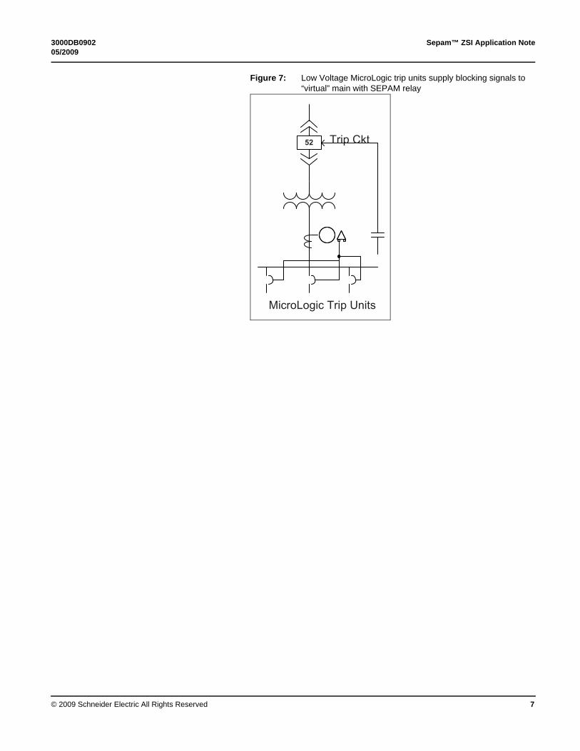
The most recent application of ZSI is between LV trip units and MV relays. Refer to Figure 7. A complete technical paper written by Van Wagner is also included in the Appendix.
ZSI is used in the following MV applications:
• Only within an MV lineup of switchgear (provides high-speed trip for bus fault). Refer to Figures 3, 5 and 5a.
• Between separated radial MV lineups of switchgear (provides high-speed trip for conductor fault). This scheme trips one breaker and removes service to all loads downstream of a tripped breaker. Refer to Figure 4.
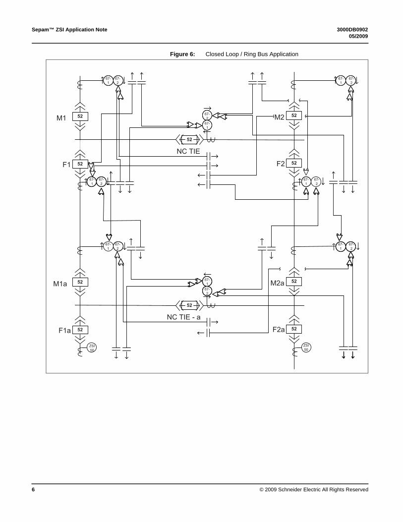
• Between separated looped MV lineups of switchgear (provides high-speed trip for conductor fault). This scheme trips two breakers to clear fault, but maintains service to other loads. Refer to Figure 6.
• LV trip units to “virtual” 480V device (MV Relay) (provides AF improvement by tripping MV feeder breaker). Refer to Figure 7.

Sepam™ ZSI Application Note 3000DB090205/2009
© 2009 Schneider Electric All Rights Reserved4
Figure 3: MV application of ZSI within the lineup
Figure 4: Radial ZSI Application for high speed line protection
52
52

3000DB0902 Sepam™ ZSI Application Note05/2009
© 2009 Schneider Electric All Rights Reserved 5
Figure 5: MV application of ZSI M-T-M
Figure 5a: Alternate MV application of ZSI M-T-M (Non-relayed Tie)
Sepam™ ZSI Application Note 3000DB090205/2009
© 2009 Schneider Electric All Rights Reserved6
Figure 6: Closed Loop / Ring Bus Application
3000DB0902 Sepam™ ZSI Application Note05/2009
© 2009 Schneider Electric All Rights Reserved 7
Figure 7: Low Voltage MicroLogic trip units supply blocking signals to “virtual” main with SEPAM relay

Sepam™ ZSI Application Note 3000DB090205/2009
© 2009 Schneider Electric All Rights Reserved8
MV Applications
Application 1 – Simple Main / Feeder ZSI Figure shows the control diagram for the main breaker shown in Figure 3, a single main with two feeders. The main breaker receives two contacts, O3 from the SEPAM relay connected to Fdr 1 and O3 from the SEPAM relay connected to Fdr 2. If either one of these contacts close, then I13 (the input on the SEPAM relay connected to the main breaker) would activate blocking of the high speed ZSI scheme and the main would not trip the ZSI element.
Figure 8: Main Bkr Control Diagram for a single main and two feeder system in Figure 3..
Figure 9 shows the SFT2841 Program Logic settings for the Main and Figure 9a shows the SFT2841 protection settings for the feeders.

3000DB0902 Sepam™ ZSI Application Note05/2009
© 2009 Schneider Electric All Rights Reserved 9
Figure 9: SFT2841 Program Logic Settings for Main
Figure 9a: SFT2841 Program Logic Settings for Feeders (also see Figure 11a) which only require an output assignment, in this case O3.
Figure 10 shows the SFT2841 protection settings for the Main and Figure 10a shows the SFT2841 protection settings for the feeders.
I11 accepts the 52b contact
I12 accepts the 52a contact
I13 accepts the blocking contacts from feeders

Sepam™ ZSI Application Note 3000DB090205/2009
© 2009 Schneider Electric All Rights Reserved10
Figure 10: SFT2841 protection settings for the Main (only Elements 1 and 3 are need for both ZSI and the backup Time-based 51 setting).
Figure 10a: SFT2841 protection settings for the Feeders
Keep in mind that the last relay in the ZSI scheme blocks ONLY. The tripping for this position in the ZSI scheme is performed by the standard 50/51 elements.
Figure 11: SFT2841 Control Matrix for the Main

3000DB0902 Sepam™ ZSI Application Note05/2009
© 2009 Schneider Electric All Rights Reserved 11
Figure 11a: SFT2841 Control Matrix for the Feeders
Recommended outputs for ZSI:
Series 20/40 – O3 and O12 (if needed)
Series 80 – O102 (Block Direction 1), O103 (Block Direction 2)
These recommended output assignments are made to avoid a conflict with other frequently used assignments. Worth mentioning is the “remote close via communication”, this function is pre-programmed in the Series 20/40 as O11, in the Series 80 it is O3. This is believed to be an ever increasing application because it allows circuit breakers to be closed without an operator standing in front of the switchgear. Presently there is a demand for the Square D Field Services designed remote open/close and racking device.
Recommended inputs for ZSI:
Series 20/40 – I13 (Direction 1 – Series 20 only has 1 direction)
Series 40 – I21 (Direction 2)
Series 80 – I104 (Direction 1), I105 (Direction 2)
NOTE: A further discussion on the meaning of “direction” is included in the application of the closed ring.
General Procedure:
1. Wire I/O
2. Configure Program Logic page
3. Configure Control Matrix
4. Configure Protection Tab which includes
a. ZSI settings
b. Phase Over current settings
c. Ground Over Current settings

Sepam™ ZSI Application Note 3000DB090205/2009
© 2009 Schneider Electric All Rights Reserved12
The ZSI scheme requires specific settings for the main and feeders. It is common for application engineers to set the ZSI (phase) pickup setting per Table 3 below:
Table 3: ZSI “Common” Pickup Settings for Blocking to Occur
*Min. PU assumes that the short circuit contribution from motors is less than the pickup value. If there is a system that has a significant motor contribution in the ZSI zone, perform the following steps:
Increase the time delay of the scheme to 200ms.
Use directional 67 element (pointing in the forward direction) to block only if the fault is downstream of the feeder. The motor contribution would be in the reverse direction.
Within a given scheme, all relays typically have the same pickup. The ground fault ZSI pickups are commonly set to 50-87% of the phase settings for a solidly grounded system. The common time delays are 100ms. As mentioned above, there may be instances where motor contribution at one level of the ZSI may cause the time delay to be 200ms and the time delays near the utility to be 100ms (the SEPAM instruction book shows this example).
Protection for most industrial feeder breakers typically allow for a ANSI 50 function (instantaneous). In the example above, the ZSI blocking is set up to 2.4kA and the feeder breakers also trip at 2.4kA. The feeder 50 setting is typically set to1.7 x maximum inrush. So if there is a fault downstream of the feeder of 3000A, the feeder would send a blocking signal to the main and simultaneously trip the feeder. Once the trip signal is sent to the feeder, the blocking signal is released 200 ms later. If the feeder breaker did not clear the fault (i.e. failed to operate), the main would immediately trip to clear the fault. Therefore the ZSI scheme has a built-in breaker failure protection.
If a feeder feeds multiple transformers and an ANSI 50 element is not used, the downstream 3000A fault would be allowed to flow until the feeder 51 element cleared (if a downstream transformer primary fuse did not clear the fault). If this were the case, the feeder would send and maintain the blocking signal and the main would not trip on the high speed element. The feeder 51 element would eventually trip (based on its setting).
Application 2 – Main-Tie-Main The normal Main-Tie-Main (M-T-M) is very common to Application 1 covered in detail above. In the M-T-M, the feeders have a second output contact to block the TIE (O12 refer to Figure 12). All settings for the feeder are the same. The TIE and Main settings in the M-T-M are just like the Main in Application 1. TIE is slightly different in that it blocks both Mains (O12 blocks M1 and O3 blocks M2); the ZSI pickup and time delay settings are the same as the Main.
Switchgear Main Bus Min. PU* Max PU
1200A 2.4-3.6kA ½ maximum three phase fault current.
2000A 4-6kA ½ maximum three phase fault current.
3000A 6-9kA ½ maximum three phase fault current.

3000DB0902 Sepam™ ZSI Application Note05/2009
© 2009 Schneider Electric All Rights Reserved 13
Figure 12: M-T-M ZSI with I/O labeled for SEPAM Series 20/40 with I/O assignments.
In Figure 12 assume the TIE is closed and M2 is Open.
Table 4: SC1, SC2 & SC3 Block and Trip Summary
Note that in “SC1 and SC2” the TIE breaker sends a blocking signal to M2 but in these cases this breaker is already open. If the N.O. TIE is closed then either M1 or M2 must be open. With this scheme, there is no need to write Boolean logic. Blocking both mains works well for this situation. If the TIE is NC, then this configuration would be considered a “closed loop” which is covered in the next application example.
Short Circuit Event CB Blocked / Blocked By / Output Contact Trip
SC1 TIE / F4 / O12 and M1 / TIE / O12 F4
SC2 M1 / TIE / O12 TIE
SC3 NONE M1

Sepam™ ZSI Application Note 3000DB090205/2009
© 2009 Schneider Electric All Rights Reserved14
Application 3 – Closed Loop System Refer to Figure 6 and Figure 13.
Figure 13: Closed Loop ZSI with I/O assignments
The closed loop system is a system that has multiple sources that are normally tied together. This could be the case with a facility that has two separate utility feeds (most common), or a system that has one utility feed and one or more generators (common in paper mills).
The benefits of this scheme are commonly used in the “critical power” area. This scheme requires a more thorough knowledge of all the power system disciplines. Special care is required when multiple sources are tied together to make certain the switchgear interrupting ratings are adequate and that reverse current relays (ANSI 67 and 67N) elements are properly applied and tested. This scheme also requires a higher level of safety training for operators and technicians. When a circuit breaker is opened in the loop, it is more likely than not that the line and load side of the breaker is still hot.
The basis of the closed loop ZSI is that within the portion of the system that is closed, each relay has two 67 elements; one looking in the forward direction and one looking in the reverse (Figure 13). The 67 Element 1 (67-1) is typically pointing in the reverse direction. The convention for choosing the direction for the relays in the system is somewhat arbitrary. Following a
3000DB0902 Sepam™ ZSI Application Note05/2009
© 2009 Schneider Electric All Rights Reserved 15
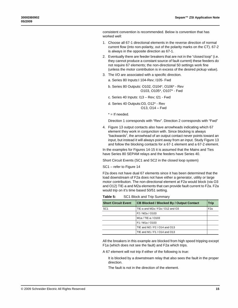
consistent convention is recommended. Below is convention that has worked well:
1. Choose all 67-1 directional elements in the reverse direction of normal current flow (into non-polarity, out of the polarity marks on the CT). 67-2 is always in the opposite direction as 67-1.
2. Eventually there are feeder breakers that are not in the “closed loop” (i.e. they cannot produce a constant source of fault current) these feeders do not require 67 elements; the non-directional 50 settings work fine (unless the motor contribution is in excess of the desired pickup value).
3. The I/O are associated with a specific direction.
a. Series 80 Inputs:I 104-Rev; I105- Fwd
b. Series 80 Outputs: O102, O104*, O106* - RevO103, O105*, O107* - Fwd
c. Series 40 Inputs: I13 – Rev; I21 - Fwd
d. Series 40 Outputs:O3, O12* - RevO13, O14 – Fwd
* = If needed.
Direction 1 corresponds with “Rev”. Direction 2 corresponds with “Fwd”
4. Figure 13 output contacts also have arrowheads indicating which 67 element they work in conjunction with. Since blocking is always “backwards”, the arrowhead of an output contact never points toward an input, but instead it will always point away from an input. Study Figure 13 and follow the blocking contacts for a 67-1 element and a 67-2 element.
In the examples for Figures 14-15 it is assumed that the Mains and Ties have Series 80 SEPAM relays and the feeders have Series 40.
Short Circuit Events (SC1 and SC2 in the closed loop system)
SC1 – refer to Figure 14
F2a does not have dual 67 elements since it has been determined that the load downstream of F2a does not have either a generator, utility or large motor contribution. The non-directional element at F2a would block (via O3 and O12) TIE-a and M2a elements that can provide fault current to F2a. F2a would trip on it’s time based 50/51 setting.
Table 5: SC1 Block and Trip Summary
All the breakers in this example are blocked from high speed tripping except F1a (which does not see the fault) and F2a which trips.
A 67 element will not trip if either of the following is true:
It is blocked by a downstream relay that also sees the fault in the proper direction.
The fault is not in the direction of the element.
Short Circuit Event CB Blocked / Blocked By / Output Contact Trip
SC1 TIE-a and M2a / F2a / O12 and O3 F2a
F2 / M2a / O103
M1a / TIE-a / O103
F1 / M1a / O103
TIE and M2 / F2 / O14 and O13
TIE and M1 / F1 / O14 and O13

Sepam™ ZSI Application Note 3000DB090205/2009
© 2009 Schneider Electric All Rights Reserved16
Figure 14: Fault Example SC1
SC-2 Refer to Figure 15.
When a fault is detected by a directional element, the ZSI blocks backwards to the source breakers that can provide fault current in that direction. For fault SC2 the 67-2 element at F1 senses current in “its” direction and closes the two output contacts that match the forward direction, in this case O13 and O14. These two contacts block the forward flowing element in M1 from tripping (67-2) and the TIE element 67-1. The 67-1 in M1 or 67-2 in the TIE does not see fault current in “their” direction. The TIE 67-1 element also blocks backwards which includes M2 67-2 and F2 67-1.

3000DB0902 Sepam™ ZSI Application Note05/2009
© 2009 Schneider Electric All Rights Reserved 17
Since the fault current coming in from M2 can split, some going through the TIE and some going through F2, M2a, TIE-a, M1a to fault, this loop must also be blocked. See the table below for complete blocking sequence.
Table 6: SC2 Block and Trip Summary
So the faulted line segment between breakers F1 and M1a is cleared quickly by the ZSI scheme and the rest of the load continues to operate. Note that some breakers are blocked more than once; the TIE is blocked by F1 and F2. The F2 block is in a direction that the TIE 67-2 element which is not picked up, so nothing occurs. Faults downstream of F2 could cause current to flow across the TIE in the 67-2 direction so this blocking is necessary.
Short Circuit Event CB Blocked / Blocked By / Output Contact Trip (Element)
SC2 M1 and TIE / F1/ O13 and O14
F1 does not receive blocking from M1a and Trips F1 (67-2)
M2 and F2 / TIE / O102 and O104
TIE and M2 / F2 / O14 and O13
F2 / M2a / O103
M1a does not receive blocking from F1 and Trips M1a (67-1)
M2a / TIE-a / O102

Sepam™ ZSI Application Note 3000DB090205/2009
© 2009 Schneider Electric All Rights Reserved18
Figure 15: Fault Scenario SC2

3000DB0902 Sepam™ ZSI Application Note05/2009
© 2009 Schneider Electric All Rights Reserved 19
SEPAM SFT2841 Settings for Closed Loop ZSI Figure 16: Closed Loop ZSI Main and Tie 51 Settings
In the closed loop system, the 67 elements (see Figure 17) perform the blocking and tripping functions, therefore only the backup time based 51 settings are needed.
Figure 17: Closed Loop ZSI Main and Tie 67 setting example.
Figure 18: Closed Loop ZSI Control Matrix – Logic/Outputs
Figure 19: Closed Loop ZSI Control Matrix – Protection/Outputs
A subtle but important point is that the blocking assignments are made in the Logic/Output section of the control matrix, not the Protection/Outputs page (refer to Figures 18 and 19). The gray outputs are the outputs controlled by the “Circuit Breaker Control” (ON) setting.

Sepam™ ZSI Application Note 3000DB090205/2009
© 2009 Schneider Electric All Rights Reserved20
Figure 20: Series 40 Feeder in the Closed Loop ZSI - 51
The feeders in the closed loop have the same setting philosophy, the 67 elements block and trip and the 51 element is for backup (see Figures 20 and 21).
Figure 21: Series 40 Feeder in the Closed Loop ZSI – 67

3000DB0902 Sepam™ ZSI Application Note05/2009
© 2009 Schneider Electric All Rights Reserved 21
Control Diagram Figure 22: Control Diagram with “external” block sending and receiving
What is unique to this scheme in comparison to the M-T-M scheme is that care must be taken so that the two different lineups of switchgear do not tie DC power (typically 125Vdc) sources together.
The convention used by the Square D Company switchgear plant in Smyrna, TN is to power the dry output contacts with the DC voltage from the “input” location. With this convention, the dry contacts are whetted at the location of the inputs. Refer to Figure 22.
125VDCSOURCE
A
PTD1
POWERSUPPLY
N(-)A2
PTD2
I13
I11 I12
RTO13
RTO14
BLOCKING SIGNALBREAKER 52-M1
BLOCKING SIGNALBREAKER 52-T
A10
A11
RTO1
RTO2
RTO3
RTO4
L5
L6
RTN15
RTN21
RTN16
53
54
12
13
RTN22
0GRD
A1L(+)
SDL52/b
SDL52/d
21
22
60
BLOCKING SIGNALFROM T3-N-01 5069PO#24383883-007
MAIN BREAKER
RTD5
RTD6
M1
M2
M4
M5
DL5CMES114S4D
DL5CMES114S4D
DL5CS40
G 10
ZSI BLOCKINGRECEPTION 1
DL5CMES114S4D
M7
M8
56
DL5CMES114012
DL5CS4D03
DL5CMES114S4
B

Sepam™ ZSI Application Note 3000DB0902Data Bulletin 05/2009
Electrical equipment should be installed, operated, serviced, and maintained only by qualified personnel. No responsibility is assumed by Schneider Electric for any consequences arising out of the use of this material.
Schneider Electric USAStreet AddressCity, State Zip Country1-888-SquareD (1-888-778-2733)www.schneider-electric.us
Square D® is a trademark or registered trademark of Schneider Electric. Other trademarks used herein are the property of their respective owners.
© 2009 Schneider Electric All Rights Reserved22
Related Documents