ANALYSIS OF MOMENT RESISTING FRAME & LATERAL LOAD DISTRIBUTION LATERAL LOAD DISTRIBUTION OF FRAME BUILDING: • In a two dimensional moment resisting frame each joint can have at the most three degrees of freedom (displacement in horizontal and vertical directions and rotation). • To tal number of degree of freedom is 3Nj where Nj is the number of joints in the frame. • In practice, beams carr ver small a!ial force and undergo negligible a!ial deformation. This means horizontal displacement at all joints located at the beam level s same. • In most buildings uptown moderate height, the a!ial deformation of columns is negligible. • Numbers of degrees of freedom are reduced to one rotation and one horizontal displacement. • "s the rotati onal inertia associ ated with the r otational degree of freedom is insigni ficant, it is further possible to reduce, through static condensation, the number of degrees to one per store for carring out dnamic analsis. • In similar wa, each joint of three dimensional frames can have at most si! degrees of freedom. • #inall , there are three degrees of freedom per floor. • #ree vibration analsis of the building can thus be carried out b solving (3N$3N) %igen value problem, where N is the number of stores in the building. • &nce natural fre'uenc and more shape is nown it is possible to obtain the ma!imum seismic force to be applied at each store level due to given earth'uae ground motion. LAT ERAL LOAD ANALYSIS OF MOMENT RESISTING FRAME: • &nce the design lateral loads are nown on the twodimensional frames, one could analze the frame for the member forces. • &ne could carr out an accurate computer analsis or an appro!imate analsis as per re'uirement. • "ppro!imate anals is is usuall per formed at preli minar design stage and to assess the computer analsis. • Tw o commonl used methods* A. Portal frame method: Frame* +ortal frames are fre'uentl used over the entrance of a bridge and as a main stiffness element in building design in order to transfer horizontal forces applied at the top of the frame to the

Welcome message from author
This document is posted to help you gain knowledge. Please leave a comment to let me know what you think about it! Share it to your friends and learn new things together.
Transcript
7/21/2019 30 - Analysis of Moment Resisting Frame and Lateral Load
http://slidepdf.com/reader/full/30-analysis-of-moment-resisting-frame-and-lateral-load 1/8
7/21/2019 30 - Analysis of Moment Resisting Frame and Lateral Load
http://slidepdf.com/reader/full/30-analysis-of-moment-resisting-frame-and-lateral-load 2/8
foundation. &n bridges, these frames resist the forces caused b wind, earth'uae, and
unbalanced traffic loading on the bridge dec. +ortals can be pin supported, fi!ed supported, or
supported b partial fi!it. The appro!imate analsis of each case will now be discussed for a
simple threemember portal.
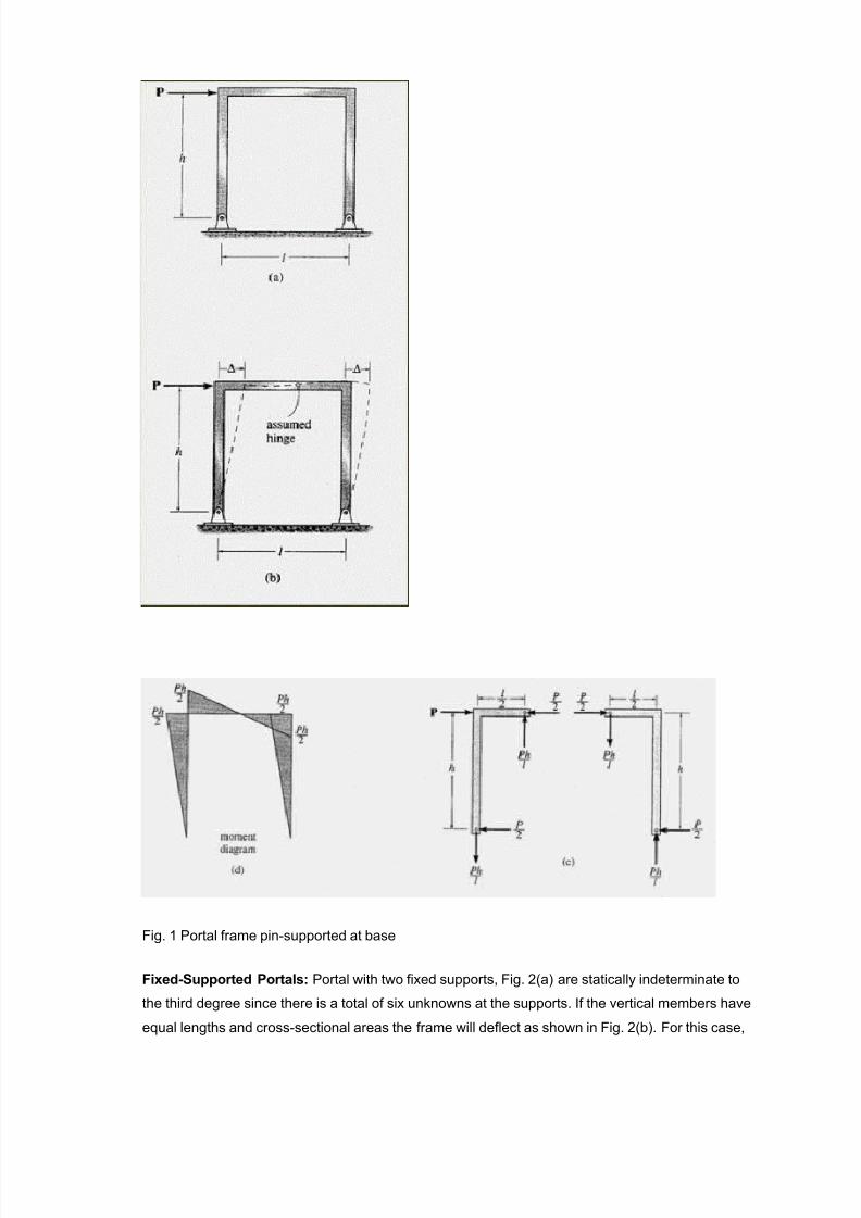
P!"#S$%%orted Portal* " tpical pinsupported portal frame is shown in #ig. (a). -ince four
unnowns e!ist at the supports but onl three e'uilibrium e'uations are available for solution, this
structure is staticall indeterminate to the first degree. onse'uentl, onl one assumption must be
made to reduce the frame to one that is staticall determinate.
The elastic deflection of the portal is shown in #ig. (b). This diagram indicates that a point of
inflection, that is, where the moment changes from positive bending to negative bending, is located
appro!imatel at the girder/s midpoint. -ince the moment in the girder is zero at this point, we can
assume a hinge e!ists there and then proceed to determine the reactions at the supports using
statics. If this is done, it is found that the horizontal reactions (shear) at the base of each column
are e'ual and the other reactions are those indicated in #ig. (c). #urthermore the moment
diagrams, for this frame, are indicted in #ig. (d).
7/21/2019 30 - Analysis of Moment Resisting Frame and Lateral Load
http://slidepdf.com/reader/full/30-analysis-of-moment-resisting-frame-and-lateral-load 3/8
#ig. +ortal frame pinsupported at base
F!ed#S$%%orted Portal: +ortal with two fi!ed supports, #ig. 0(a) are staticall indeterminate to
the third degree since there is a total of si! unnowns at the supports. If the vertical members have
e'ual lengths and crosssectional areas the frame will deflect as shown in #ig. 0(b). #or this case,

7/21/2019 30 - Analysis of Moment Resisting Frame and Lateral Load
http://slidepdf.com/reader/full/30-analysis-of-moment-resisting-frame-and-lateral-load 4/8
we will assume points of inflection occur at the midpoints of all three members, and therefore
hinges are placed at these points. The reactions and moment diagrams for each member can
therefore be determined b dismembering the frame at the hinges and appling the e'uations of
e'uilibrium to each of the four parts. The results are shown in #ig. 0(c). Note that, as in the case of
the pinconnected portal, the horizontal reactions (shear) at the base of each column are e'ual. The
moment diagram for this frame is indicted in #ig. 0(d).
#ig. 0 "nalsis of portal frames 1 #i!ed at base
Part!all' F!ed (at the Bottom) Portal: -ince it is both difficult and costl to construct a perfectl
fi!ed support or foundation for a portal frame, it is a conservative and somewhat realistic estimate
to assume a slight rotation to occur at the supports, as shown in #ig. 3(a). "s a result, the points of
inflection on the columns lie somewhere between the case of having a pinsupported portal (as
shown in #ig. (a)), where the 2inflection points are at the supports (base of columns), and that of a
fi!edsupported portal (as shown in #ig. 0(a)), where the inflection points lie at the center of the

7/21/2019 30 - Analysis of Moment Resisting Frame and Lateral Load
http://slidepdf.com/reader/full/30-analysis-of-moment-resisting-frame-and-lateral-load 5/8
columns. 4an engineers arbitraril define the location at h53 (#ig. 3(b)), and therefore place hinges
at these points, and also at the center of the girder.
#ig. 3 +ortal frame partiall fi!ed at base
Tr$ed Frame* 6hen a portal is used to span large distances, a truss ma be used in place of
the horizontal girder. -uch a structure is used on large bridges and as transverse bents for large
auditoriums and mill buildings. " tpical e!ample is shown in #ig. 7(a). In all cases, the suspended
truss is assumed to be pin connected at its points of attachment to the columns. #urthermore, the
truss eeps the columns straight within the region of attachment when the portals are subjected tothe sideswa 8, #ig. 7(b). onse'uentl, we can analze trussed portals using the same
assumptions as those used for simple portal frames. #or pinsupported columns, assume the
horizontal reactions (shear) are e'ual, as in #ig. (c). #or fi!edsupported columns, assume the
horizontal reactions are e'ual and an inflection point (or hinge) occurs on each column, measured
midwa between the base of the column and the lowest point of truss member connection to the
column. -ee #ig. 0(c) and #ig. 7(b).

7/21/2019 30 - Analysis of Moment Resisting Frame and Lateral Load
http://slidepdf.com/reader/full/30-analysis-of-moment-resisting-frame-and-lateral-load 6/8
#ig. 7 Trussed frame fi!ed at base
9ateral loads on :uilding #rames* +ortal #rame 4ethod
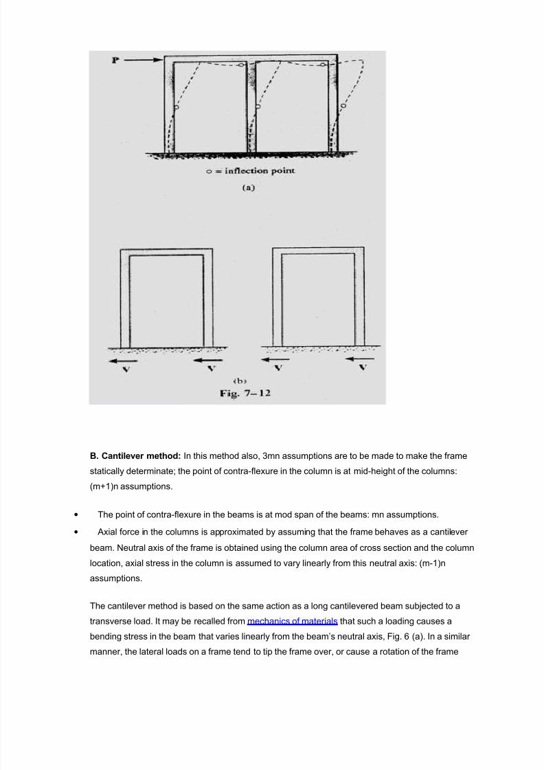
The action of lateral loads on portal frames and found that for a frame fi!ed supported at its base,
points of inflection occur at appro!imatel the center of each girder and column and the columns
carr e'ual shear loads, #ig. 0. " building bent deflects in the same wa as a portal frame, #ig.; (a),
and therefore it would be appropriate to assume inflection points occur at the center of the columns
and girders. If we consider each bent of the frame to be composed of a series of portals, #ig. ; (b),
then as a further assumption, the interior columns would represent the effect of two portal columns
and would therefore carr twice the shear < as the two e!terior columns.
onsider the 08 frame with mbase and nstores. The degree of indeterminac of the frame is
3mn. To analze the frame, 3mn assumptions are made=
• The point of contrafle!ure in the column is at midheight of the columns* (m>)n assumptions.
• The point of contrafle!ure in the beams is at the mid span of the beams* mn assumptions.
• "!ial force in the internal columns is zero (m>)n assumptions.
• 6ith the above assumptions, the frame becomes staticall determinate and member forces are
obtained simpl b considering e'uilibrium.
7/21/2019 30 - Analysis of Moment Resisting Frame and Lateral Load
http://slidepdf.com/reader/full/30-analysis-of-moment-resisting-frame-and-lateral-load 7/8
B. *a"t!le+er method: In this method also, 3mn assumptions are to be made to mae the frame
staticall determinate= the point of contrafle!ure in the column is at midheight of the columns*
(m>)n assumptions.
• The point of contrafle!ure in the beams is at mod span of the beams* mn assumptions.
• "!ial force in the columns is appro!imated b assuming that the frame behaves as a cantilever
beam. Neutral a!is of the frame is obtained using the column area of cross section and the column
location, a!ial stress in the column is assumed to var linearl from this neutral a!is* (m)n
assumptions.
The cantilever method is based on the same action as a long cantilevered beam subjected to a
transverse load. It ma be recalled from mechanics of materials that such a loading causes a
bending stress in the beam that varies linearl from the beam/s neutral a!is, #ig. ? (a). In a similar
manner, the lateral loads on a frame tend to tip the frame over, or cause a rotation of the frame

7/21/2019 30 - Analysis of Moment Resisting Frame and Lateral Load
http://slidepdf.com/reader/full/30-analysis-of-moment-resisting-frame-and-lateral-load 8/8
about a 2neutral a!is ling in a horizontal plane that passes through the columns at each floor level.
To counteract this tipping, the a!ial forces (or stress) in the columns will be tensile on one side of
the neutral a!is and compressive on the other side as in #ig below. 9ie the cantilevered beam, it
therefore seems reasonable to assume this a!ial stress has a linear variation from the centroid of
the column areas or neutral a!is. The cantilever method is therefore appropriate it the frame is tall
and slender, or has columns with different crosssection areas.
Related Documents