Ease of integration - valve size matches pipe size, resulting in reduced installation time and installation costs to suit installation Low pressure drop - compared to other valve types Small physical size Hand wheel allows manual adjustment of valve up and maintenance Charge air cooling Secondary cooling systems Fuel and lube oil preheating Co-generation Engine jacket water Waste heat boilers Product coolers Product heaters Product condensers GG valve GG valve G valve compared with a typical equivalent Model G, Version G and Accessories DS-GG-Temp-Control-Valve-0615-rev10 3-Way Temperature Control Valve

Welcome message from author
This document is posted to help you gain knowledge. Please leave a comment to let me know what you think about it! Share it to your friends and learn new things together.
Transcript

��������� ��Ease of integration - valve size matches pipe size, resulting in reduced installation time and installation costs
�� �������������� ���������������������� to suit installation
��Low pressure drop - compared to other valve types
��Small physical size
��Hand wheel allows manual adjustment of valve ������������������������������ ������������ up and maintenance
��� �������� �� ��� ������� ������� �������������������������������
��Charge air cooling
��Secondary cooling systems
��Fuel and lube oil preheating
��Co-generation
��Engine jacket water
���������� ������� ��������� ����� ���������� ���
��Waste heat boilers
��Product coolers
��Product heaters
��Product condensers
����� �� GG valve
������ �� GG valve
�����!��������
�������
G valve compared with a typical equivalent ������������������������
Model G, Version G and Accessories
DS-GG-Temp-Control-Valve-0615-rev10 ���"���"���
3-Way Temperature Control Valve

page 2 DS-GG-Temp-Control-Valve-0615-rev10
3-Way Temperature Control Valve - Model G, Version G
Contents#!��! ���"""""""""""""""""""""""""""""""""""""""""""""""""""""�$
%��� �� ��� �""""""""""""""""""""""""""""""""""""""""""""""�$�
&���������""""""""""""""""""""""""""""""""""""""""""""""�'
#!��! ����( V��!��)���� """"""""""""""""""""""""""""�*
� ������������� ����������������������������������������������
� �������!���������� �����������������������������������"
� #�������$���������������������������������������������������%
+ ��� ���""""""""""""""""""""""""""""""""""""""""""""""""��,$ #!��! ����(������ ��%��� ���"""""""""""""""""""�,-
������� ���� �����"""""""""""""""""""""""""""""""""�,*
#!��! ����(������� ��%��� ���""""""""""""""�,*
.�����#�����"""""""""""""""""""""""""""""""""""""""""""""�,/
%����� ��"""""""""""""""""""""""""""""""""""""""""""""""�,0
� &'(�)����������*+".(/�*+"4(/���7�8"9*.�����.*
� : ;����&<�.++�<�����������������*+�+�������.*
� �����������7���=�������*+":)�������������������.%
� >�������&���������)���������*+�8?��������������.%
� >�������&���������)���������*+�8)��������������4+
� &���������'��������)�����������@*+�������������4+

page 3 DS-GG-Temp-Control-Valve-0615-rev10
3-Way Temperature Control Valve - Model G, Version G
AMOT G valves are 3-way control valves consisting of a heavy duty rotary valve and either a quarter turn electric or pneumatic ����������<B�����������������B��B�������of accuracy and repeatability for accurate temperature control and are equally accurate ������������������������������������I���J�I���������
The heavy duty rotor design provides tight temperature control without high maintenance ��K����������<B��=��������������������B������������������������������N���������Q����������Q����������� ���������/����������J��������=�����������K����������(������
for high vibration service, the AMOT G valves ����K����������R��=���������7�K�������������B���������������#������������������=��������to reciprocating machinery, such as diesel ������/�I��B������������������������<B��B���=�duty actuators are specially reinforced to provide �������������������
The standard valves are suitable for a variety ���J�����B���I����/�I����U��=���/����I����/����������������B=������������!����������=�materials are available for services involving =��B�����������������������/������$��I��������������������������������
Applications
Overview
1������% �������������1�����The intercooler is used to cool high temperature �������B�����������
'���B���������������B��@�#���������������B��J�I�of cooling water through an intercooler, increasing ��������=/���B����������������������B������������������=������������������K���������
+ !�� ���%��� �� ��Jacket water cooling in diverting applications regulates the outlet coolant water temperature ��������������������������<B�����������B���sends water to a cooler or bypass loop, accurately �������������B���������������
The temperature is normally measured at the �������������B��B����������
2 � ���%��� �� ��Lubricating oil temperature control is normally ����������������������������������������������B�������������������������B��B���������<B��temperature is normally measured as close as �����������B�������������
�����8�DS-GG-Temp-Control-Valve-0615-rev10
3-Way Temperature Control Valve - Model G, Version G
����� ��&����
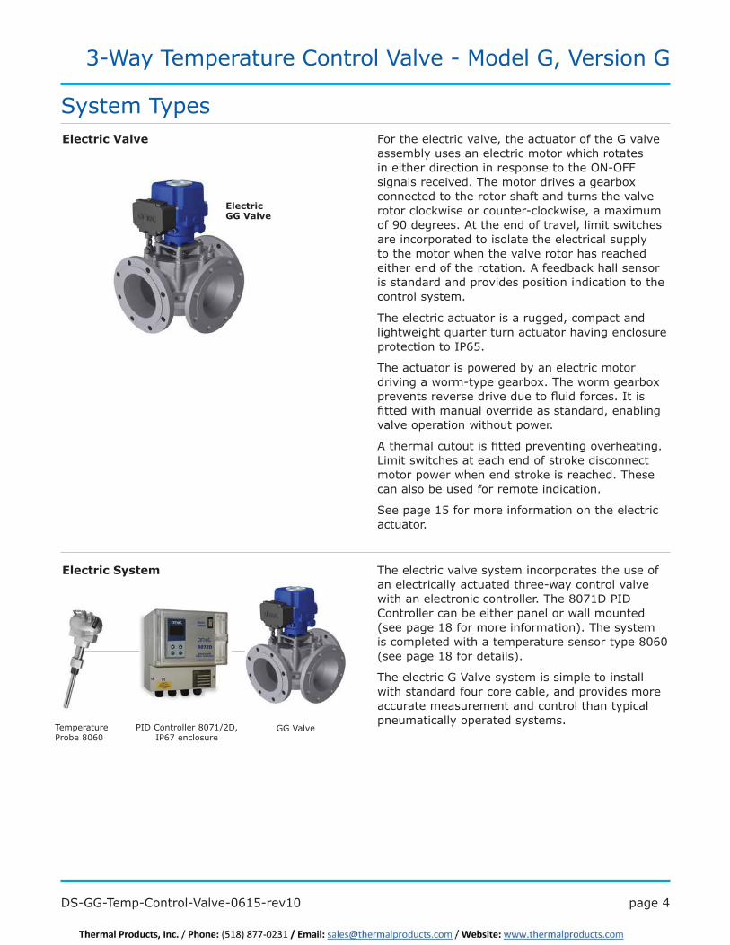
The electric actuator is a rugged, compact and lightweight quarter turn actuator having enclosure ��������������'&�9��
The actuator is powered by an electric motor ���������I��� �=������������<B��I��������������������������������������J����������'���������I��B�����������������������/��������������������������I��B������I����
?��B�����������������������������������B��������Limit switches at each end of stroke disconnect ��������I���IB���������Y��������B���<B�����������������������������������������
See page 15 for more information on the electric ���������
GG Valve&'(�)����������*+".U4(/�'&�"���������
For the electric valve, the actuator of the G valve assembly uses an electric motor which rotates in either direction in response to the ON-OFF ���������������<B�����������������������connected to the rotor shaft and turns the valve rotor clockwise or counter-clockwise, a maximum ���%+��������?���B��������������/�������I���B��are incorporated to isolate the electrical supply to the motor when the valve rotor has reached ���B����������B������������?�������Y�B���������is standard and provides position indication to the ��������=����
����� ��3��!�
The electric valve system incorporates the use of an electrically actuated three-way control valve I��B���������������������������<B��*+".(�&'(�Controller can be either panel or wall mounted ���������.*������������������������<B��=����is completed with a temperature sensor type 8060 ���������.*��������������
The electric G Valve system is simple to install with standard four core cable, and provides more accurate measurement and control than typical ������������=���������=����
Temperature Probe 8060
System Types
����� �� GG Valve
page 5 DS-GG-Temp-Control-Valve-0615-rev10
3-Way Temperature Control Valve - Model G, Version G
������4������ ��&��� The electro-pneumatic valve system combines both electric and pneumatic technology, consisting of a pneumatically actuated three-way control valve with an electro-pneumatic converter, type *+�8?�����������.%�����������������
The probe sends a resistance signal to the ���������������������/�IB��B��������������8����4+�?�������������'U&������������B������������B������������������������
The electro-pneumatic system combines the features and functionality of the AMOT electronic ��������=����I��B��B������ �����������������������������������=���������������
GG ValveElectro-Pneumatic Converter
*+�8?
Temperature Controller
*+".(
Temperature Probe 8060
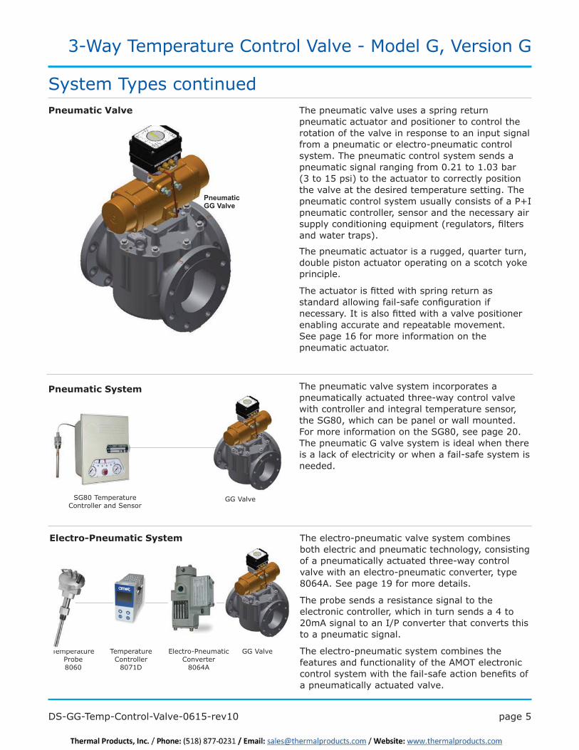
������ ��3��!� The pneumatic valve uses a spring return pneumatic actuator and positioner to control the rotation of the valve in response to an input signal from a pneumatic or electro-pneumatic control =�����<B��������������������=��������������������������������������+�4.����.�+:�����(3 to 15 psi) to the actuator to correctly position �B������������B���������������������������<B��pneumatic control system usually consists of a P+I pneumatic controller, sensor and the necessary air ����=��������������K������������������/����������I�����������
������ ��&��� The pneumatic valve system incorporates a pneumatically actuated three-way control valve with controller and integral temperature sensor, �B���@*+/�IB��B�����������������I��������������������������������������B���@*+/���������4+��The pneumatic G valve system is ideal when there is a lack of electricity or when a fail-safe system is �����
The pneumatic actuator is a rugged, quarter turn, double piston actuator operating on a scotch yoke �����������
<B������������������I��B��������������������������I�������� ��������������������������=��'�������������I��B���������������������������������������������������������������See page 16 for more information on the �������������������
SG80 Temperature Controller and Sensor
System Types continued
Pneumatic GG Valve
GG Valve

page 6 DS-GG-Temp-Control-Valve-0615-rev10
3-Way Temperature Control Valve - Model G, Version G
�������������������� "4+�3UB�� :/."+�`������� ����������I��B�B��B���J�I������������B����@>�{@&({<���{)������{#�����
& 5�N� &�������6�� . ���6��
80mm - 250mm (3” - 10”) 80mm - 200mm (2” - 8”) ����49+�����.+|��B��B�J�I�������������(���B����@>�{@&({<���{)������{#����
)�������� ��� Ductile iron High performance iron, for fresh water, lubricating oils
&�������� ���� Flourocarbon (Viton, FKM)
�������� >~�.+%4/�?��>�����'�����������
2�� ���� ������� !��!���������� .+����� �.89������
2�� �������������� 100°C (212°F) �(�6� ���
3 ��� ���� >������B����K������������R��=��7�������<=���?���������=���/� � <����������������~������./�4++4/�#���������<���4�� �������B����������������������N
���7�����������
+ �������� %������� �� 8����9
5 - 25 Hz �U �.���� �U �.����
25 - 100 Hz �U �9�+���8%��U2) �U �8�+���:%��U2)
100 - 300 Hz �U �.�+���%�*.��U2��%+�minute
No requirement
Overview of Valve Body����(������������������Lightweight and compact
��)���������������� �����I����J��������=����installation
� Low pressure drop - enables savings on either valve or pump size
� High accuracy providing better temperature control
3��!��)���
�����"�DS-GG-Temp-Control-Valve-0615-rev10
3-Way Temperature Control Valve - Model G, Version G
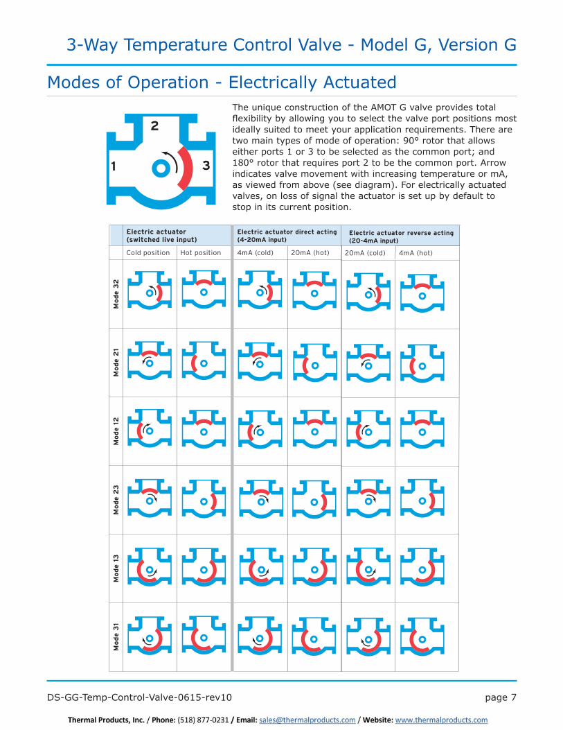
The unique construction of the AMOT G valve provides total J��������=��=�����I����=�������������B������������������������������=��������������=������������������K����������<B���������I��������=����������������������N�%+���������B�������I����B��������.����:�����������������B�������������Q����.*+���������B�����K����������4��������B���������������?���I�indicates valve movement with increasing temperature or mA, �����I�����������������������������������������=���������valves, on loss of signal the actuator is set up by default to ��������������������������
Electric actuator (switched live input)
Electric actuator direct acting(4-20mA input)
Electric actuator reverse acting(20-4mA input)
Cold position Hot position 4mA (cold) 20mA (hot) 20mA (cold) 4mA (hot)
23
ed
oM
12
ed
oM
21 e
do
M3
2 e
do
M31
ed
oM
13
ed
oM
3
2
1
Modes of Operation - Electrically Actuated
page 8 DS-GG-Temp-Control-Valve-0615-rev10
3-Way Temperature Control Valve - Model G, Version G
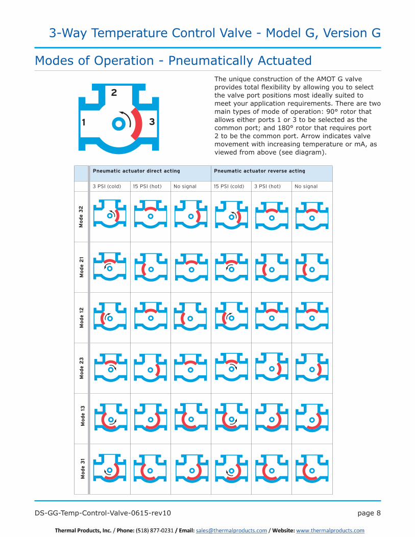
The unique construction of the AMOT G valve �������������J��������=��=�����I����=������������the valve port positions most ideally suited to �����=������������������K����������<B���������I��������=����������������������N�%+���������B���allows either ports 1 or 3 to be selected as the �����������Q����.*+���������B�����K����������4��������B���������������?���I���������������movement with increasing temperature or mA, as ���I�������������������������
Pneumatic actuator direct acting Pneumatic actuator reverse acting
3 PSI (cold) 15 PSI (hot) No signal 15 PSI (cold) 3 PSI (hot) No signal
23
ed
oM
12
ed
oM
21 e
do
M3
2 e
do
M31
ed
oM
13
ed
oM
3
2
1
Modes of Operation - Pneumatically Actuated

�����%�DS-GG-Temp-Control-Valve-0615-rev10
3-Way Temperature Control Valve - Model G, Version G
�� �� �� �� �� ������ � �
� *+��:�� 9+��4�� "� .8� 4+� 4��� � � ::� � � :%�� �� 8�� �� �� 94�
� .++��8�� *+��:�� .%� :9� 9.� �"�� � � *:� � � %%�� �� ..9�� �� .:.��
� .9+����� .++��8�� 4%� 98�� "%�� .+8�� ����� .4%�� ���� .98�� �� ."%�� �� 4+8�
� 4++��*�� .9+����� ��� .44�� ."*�� 4:9�� � � 4%.�� � � :8"�� �� 8+:����� �� 89%��
� � 4++��*�� ..*� 4.*� :.*� 8.*� � � 9."� � � �."� �� "."�� �� *."
250 (10)
300 (12) 250 (10)
� :9+��.8�� :++��.4�� �
� 8++��.��� :9+��.8�� �
� 89+��.*�� 8++��.���
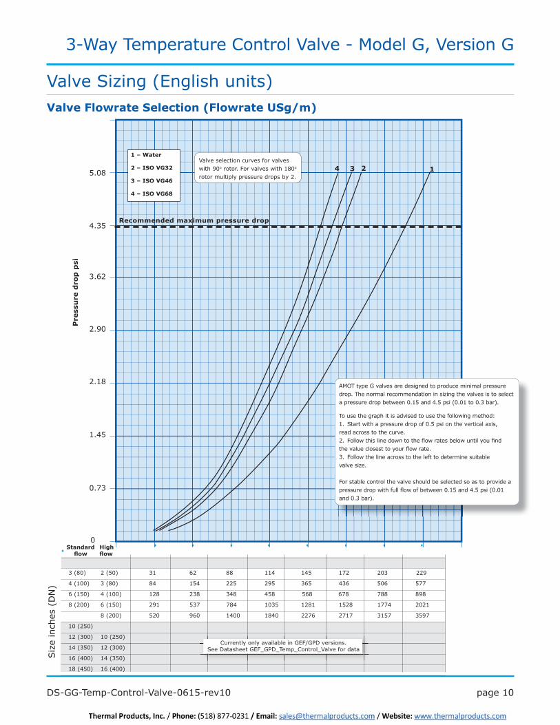
Valve Sizing (Metric units)
:�������������� ���������������
,' $ 2
,�<�=���
>�<�?&#�3@$>
$�<�?&#�3@'*
'�<�?&#�3@*0
Valve selection curves for valves I��B�%+o������������������I��B�.*+o �������������=�������������=�4�
AMOT type G valves are designed to produce minimal pressure �����<B���������������������������$�����B�����������������������������������I����+�+.����+�:������+�.9���� 8�9�����
<������B������B������������������B�������I�������B�N .�� ������I��B�����������������+�+9������� �� �B��������������/��������������B�������� 4�� �����I��B��������I������B��J�I����������I�� �� ������=�������B�����������������=����J�I������ :�� �����I��B����������������B������������������� � ���������������$��� For stable control the valve should be selected so as to provide �������������I��B������J�I�������I����+�+.����+�:����� �+�.9����8�9������
&������� ���. �� ����6��� ���6��
Siz
e D
N (
inch
es)
3��!����������&���� ���A���������3B��C
)�������=����=��������������@>�U@&(��������� ����(���B����@>�{@&({<���{)������{#������������
0
+�+9
+�.+
+�.9
+�4+
+�49
+�:+
+�:9
+�8+
���
�
����
���
����
page 10 DS-GG-Temp-Control-Valve-0615-rev10
3-Way Temperature Control Valve - Model G, Version G
�� �� �� �� �� �� �� ���
�
� :��*+��� 4��9+�� :.� � �4�� � �**� � � ..8�� � .89� � ."4� � 4+:��������������44%
� 8��.++�� :��*+�� *8� � .98� � �449�� � 4%9�� � :�9� � 8:�� � 9+�� 9""
� ���.9+�� 8��.++�� .4*� � 4:*� � �:8*����� � 89*�� ����9�*� ���"*��� "**� *%*
� *��4++�� ���.9+�� 4%.� ������ 9:"�� � �"*8�� � .+:9�� � .4*.�� � .94*�� .""8����� 4+4.
� � *��4++�� 94+� � %�+� � �.8++� � .*8+� � 44"�� � 4"."� :.9"� :9%"
10 (250)
12 (300) 10 (250)
� .8��:9+�� .4��:++�� �
� .���8++�� .8��:9+�
� .*��89+�� .���8++��
Valve Sizing (English units)3��!����������&���� ���A��������D&�B�C
&������� . �� ����6��� 6��
Siz
e in
ches
(D
N)
���
�
����
���
��
:�������������� ���������������
,' $ 2
,�<�=���
>�<�?&#�3@$>
$�<�?&#�3@'*
'�<�?&#�3@*0
9�+*
8�:9
:��4
4�%+
4�.*
.�89
+�":
0
AMOT type G valves are designed to produce minimal pressure �����<B���������������������������$�����B������������������� ����������������I����+�.9����8�9�����+�+.����+�:������
<������B������B������������������B�������I�������B�N .�� ������I��B���������������� +�9��� on the vertical axis, �������������B�������� 4�� �����I��B��������I������B��J�I����������I�������=���������B�����������������=����J�I������ :�� �����I��B����������������B���������������������������� ��������$��� For stable control the valve should be selected so as to provide a �����������I��B������J�I�������I����+�.9����8�9�����+�+.� ���+�:�������
)�������=����=��������������@>�U@&(��������� ����(���B����@>�{@&({<���{)������{#������������
Valve selection curves for valves I��B�%+o������������������I��B�.*+o �������������=�������������=�4�

page 11 DS-GG-Temp-Control-Valve-0615-rev10
3-Way Temperature Control Valve - Model G, Version G
�����B�����������������������������������J����B���I����/��B�������I��������������������N
#�����=N������B��������=�����B��J������IB��B��B����������������������<B��������=����������=������������������Y���;B����'�!���������/�the grade number is also the viscosity eg ISO #@8����8���������Y�����8+�)��.+8����
#�����=�����������N��=�������B�����������������B�����I/��B��J�I�������������������������������������������B���<B��������������������������������the graph should then be multiplied by the original J�I������������IB��B������B�������������B���������������$�������������
��� ���� �
Oil �&
SAE 5W ��*
SAE 10W 32
SAE 20 8�
SAE 20W 68
SAE 30 100
�?>�8+ 150
SAE 50 220
@����� �
Oil �&
�?>�"9; 22
SAE 80W 8�
SAE 85W 100
�?>�%+ 150
�?>�.8+ 8�+
&%��# ��3 �� ��
Some approximate viscosities (cSt) of SAE oils at 8+�)��.+8��������B�I������I/��������������������������������������B������
3 �� ��1����� ���1��!��A�!C
3 �� ��A1�� �E�C
Valve Sizing
����������
������B������B�����IN� .++����������������������������+��*
+��*���J�I�����������������������J�I�������������������)��
Some approximate viscosities (cSt) of �?>��������8+�)��..+��������B�I��below, based on leading oil manufacturers �����B������
3 �� ��1����� ��
1��
���
��
����
��

page 12 DS-GG-Temp-Control-Valve-0615-rev10
3-Way Temperature Control Valve - Model G, Version G
The G valve is designed to produce ��������������������<B���������recommendation when determining the size of an AMOT G valve is a ��������������I����+�+.����+�:������.�9����8�9���������� Kv and )��������������������������%+������������������=��
3��!���������
Size DN A �C
&��������6��
0I A$C
,II A'C
,-I A*C
>II A0C
>-I A,IC
$II A,>C
$-I A,'C
'II A,*C
'-I A,0C
. ���6��
-I A>C
0I A$C
,II A'C
,-I A*C
>II A0C
>-I A,IC
$II�A,>C
$-I A,'C
'II A,*C
Kv 82 4+" 323 "4% .4%�
Cv %� 484 :"* 851 1513
�����B������������I����������������������)�N
Valve Sizing3��!��& 5 ���1������ ��
�������+���
<B��?�!<�@�#����������������B��B�������������When used in a reasonably balanced pressure system there will be some small amounts of ���Y�������I����������<B�������������������leakage will vary with the pressure difference
3��!��)���������������I�����B���������)������?�!<���������B���information if the application is sensitive to leakage rates or if high pressure differences are ��Y��=�����������
)�������=����=��������������@>�U@&(��������� ����(���B����@>�{@&({<���{)������{#������������
There are two other ways that this formula can be used to ����B��J�I����`��������U�������������������������� ���������&�'N
<B����������������������������B�����������������N
DpSGKv = Q
Q = Flow (m3UB�
Dp = Pressure drop (bar)
�@�����������������=����J��
�����#�����J�I�����������
<B����������������������������B��)��������������N
DpSGCv = Q
�������I��`��������U����
Dp = Pressure drop (psi)
�@�����������������=����J��
)����#�����J�I�����������
There are two other ways that this formula can be used to ����B��J�I�����3UB��������������������������������N
SGDpQ = Kv
KvQDp = SG
SGDpQ = Cv Cv
QDp = SG 22
������B��J�I����������������������������'������������B��J�I�������������������������B������3UB�����I�������������������������.���������I��B��������������������B�����������.������)�����B�����������������������'������������B��J�I���������`��@��������������������������I��������������������������+����B���B����I��B��������������������B�����������.������������+�*�9�)��U�)����.�.9�����

page 13 DS-GG-Temp-Control-Valve-0615-rev10
3-Way Temperature Control Valve - Model G, Version G
Dimensions
&��������,'� (���� ��� ��
����� ������%������� ��2������#!��� ��
������ ������%������� ��2������#!��� ��
������ ������ %�����

�����.8�DS-GG-Temp-Control-Valve-0615-rev10
3-Way Temperature Control Valve - Model G, Version G
Dimensions continued
NB A B C D E R S T U V W X Y Z R* S* T* U* V* W X Y Z
03GGS 207 200 107 03GGS
03GGH 227 200 127 03GGH
04GGS 242 229 128 04GGS
04GGH 281 224 169 04GGH
06GGS 312 285 169 06GGS
06GGH 346 285 191 100 06GGH
08GGS 371 343 191 08GGS
08GGH 418 340 253 08GGH
10GGS 455 406 253 10GGS
10GGH 521 405 292 10GGH
12GGS 533 292 12GGS
12GGH 631 346 12GGH
NB A B C D E R S T U V W X Y Z R* S* T* U* V* W X Y Z
03GGS 8.2 7.9 4.2 03GGS
03GGH 8.9 7.9 5.0 03GGH
04GGS 9.5 9.0 5.0 04GGS
04GGH 11.1 8.8 6.7 04GGH
06GGS 12.3 11.2 6.7 06GGS
06GGH 13.6 11.2 7.5 3.94 06GGH
08GGS 14.6 13.5 7.5 08GGS
08GGH 16.5 13.4 10.0 08GGH
10GGS 10.0 20.4 10.2 17.9 16.0 10.0 10GGS
10GGH 20.5 15.9 11.5 10GGH
12GGS 12.0 23.6 11.8 21.0 19.0 11.5 12GGS
12GGH 24.8 19.0 13.6 12GGH
4.53 2.09
14.29 18.78 5.87 2.09
2.13 10.24 2.99 5.59 5.79
4.456.10 7.87 1.77 3.11 11.69 14.25
9.29 11.73 15.75 6.14 5.202.76 11.42 3.23 6.30 6.18
2.56
7.68
5.51 2.68
8.70
157 236 298 400
260 76 142 147
113155 200
8.0 17.7 8.9
250
300
520
600
260
300
3.0 11.0 5.5
Valve Type
4.0 11.8 5.9
6.0 14.6 7.3
Valve Type
Valve TypeValve Body Electrically Actuated
483
65
221
195
140 68
54
70 290 82 160
Valve Body
45 79 297
Valve Type
95 123 100 52 52 245 192
Pneumatically ActuatedElectrically Actuated
80 280 140
200
150
100
225450
185370
150300
7.56 3.74 2.09
Pneumatically Actuated
362 115 53
53149477363132156
95 53
3.74 4.84 3.94 2.05 2.05 9.65
��7�����������=�����������������������I��B����������������������
����B�����������������������B������������������������B��������B������������������������������������������������������K����
+ ��� ��� ����
+ ��� ��� �� ����

page 15 DS-GG-Temp-Control-Valve-0615-rev10
3-Way Temperature Control Valve - Model G, Version G
����(�����������������Self-locking with minimum backlash in the
transmission - prevents valve movement ������J�I
��Auxiliary limit switches for user connection
������������������������������ �������can be operated in event of power failure
� Two torque switches - provide protection in event of actuator overloading
Overview of Electric Actuation
������������������ 115V ��.+�����4:+#���.+�� 9+U�+�$��������B��
8 � �� ���� <I������U������&(<� 49+#�?)/�.+?
2���������������� �� Fitted as standard
%���������� ��� 110° max Quarter turn
�� ������� Contactless half effect
1���������� 4����49���.�9� '&�*������������
2����� ������ Two adjustable screws
2�������!��� �� Fitted as standard
2��� �� Steel, aluminum alloy, aluminum bronze, polycarbonate
����������� �� Dry powder polyester
=���������(���������� '&�"/�~>�?�8�����
%�� ������������� 4+�)�����*9�)� � 8�������.*9���
%�� ������ � �� %+��7���������� ���������
%� 4������� ��������� "� �.+;
3 ��� ����� ���� 5 - 100 Hz 5g
100 - 300 Hz 1g
���(��������� � +���������>IL1� &��E�� ���A��C� 2�����������A%C
&�������� . ���6��� � � -I�.5� *I�.5 >>I3� ,,I3
50 )�������=����=��������������@>�U@&(�������������(���B����@>�{@&({<���{)������{#������������
*+� �4++� *+� �4++� � �9�� 49� 4.� +�**� .�"��
49+� �89+� 49+� �8++� � )�������=����=��������������@>�U@&(�������������(���B����@>�{@&({<���{)������{#������������
����� ��%�����

page 16 DS-GG-Temp-Control-Valve-0615-rev10
3-Way Temperature Control Valve - Model G, Version G
<B��?�!<���������U���������������������������������������������=�������8 4+�?���������demand input signal, and uses this to operate ������������������I���B�������������B��������� The microprocessor based unit uses the signal from the contactless position sensor to accurately position the actuator, taking into account motor ����������������������������B���� The positioner is split into two parts, housed in the ��������������<B����������I��������/����IB��B�all high voltage circuits are fully encapsulated to I��B����B��B����������/��������������������<B�����������I�������=�������������
`��������������������IN
��<B���������������������������8 4+�?/���� + 4+�?/�+ 9#/�+ .+#����4 .+#��=�I���B��� �� 8 4+�?�������/�IB��B�B�I���������������� �������/�������������������������������B���� ������������������
��?�I���B�����I�������=������������������ � which end of stroke corresponds with a � 8�?������
��The action on sensor fail can be selected � ������������������B����B��8�?�����B��4+�?� � �������/�������������=������������������
��The deadband can be increased to aid � ������������I��B����=�������������
��When necessary, such as after maintenance, the actuator can be recalibrated at the touch �� �������������
Electronic Positioner
Overview of Pneumatic Actuation
����(�����������������A rugged quarter turn, double piston, rack
and pinion pneumatic actuator with spring ����������������������������������
��)������������������� ���
������������.�� ��� )���������������/����������������I�������&��=����B�������������B�
&������������� �����*����� �%+����..9����
& ������������ +�4.����.�+:����� �:����.9�����
������������� ��� G .U8�� �.U8�~&<�
2�������!��� �� Optional
������ ��%�����
There are three LEDs on the terminal box on the side of the actuator, providing clear visual indication ������������������<I�������������������I�����������������������������
������� ���� ����
�����."�DS-GG-Temp-Control-Valve-0615-rev10
3-Way Temperature Control Valve - Model G, Version G
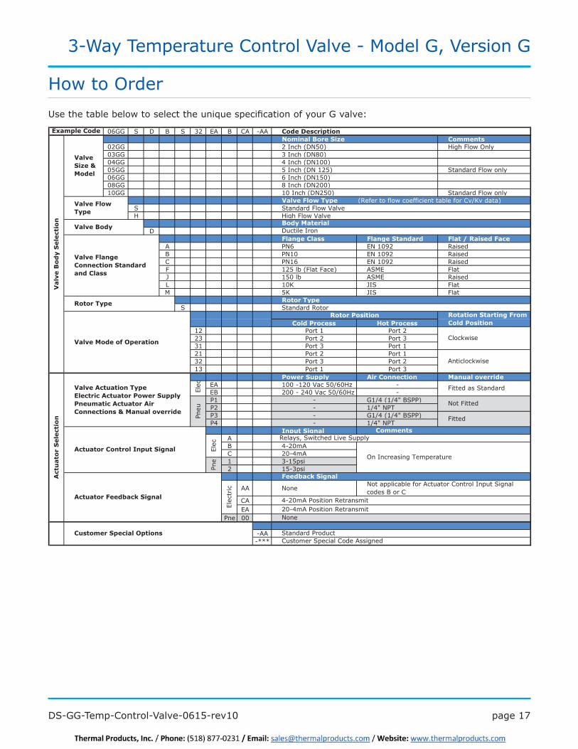
06GG S D B S 32 EA B CA -AA 1����+��� � ����� ����)����& 5� 1�����
02GG 2 Inch (DN50) High Flow Only03GG 3 Inch (DN80)+8@@ 8�'��B��(~.++�05GG 5 Inch (DN 125) Standard Flow only06GG 6 Inch (DN150)08GG 8 Inch (DN200)10GG 10 Inch (DN250) Standard Flow only
3��!����������� �7�����������I�����������������������)�U�������S Standard Flow ValveH High Flow Valve
D�������1�� �������&������ ����B�:� �������
A PN6 >~�.+%4 7���B PN10 >~�.+%4 7���C PN16 >~�.+%4 7���F 125 lb (Flat Face) ASME Flat J 150 lb ASME 7���L 10K JIS FlatM 5K JIS Flat
:��������S �������7����
1��������� .�������12 Port 1 Port 223 Port 2 Port 331 Port 3 Port 121 Port 2 Port 132 Port 3 Port 213 Port 1 Port 3
������&����� % ��1����� �� 2�������!��� ��EA .++� .4+�#���9+U�+�$ -EB 4++� �48+�#���9+U�+�$ -P1 - @.U8��.U8����&&�P2 - .U8��~&<P3 - @.U8��.U8����&&�&8 - .U8��~&<
?����& ����AB 8 4+�?C 4+ 8�?1 3-15psi2 15-3psi
AA None
CAEA
Pne 00
-AA-***
Ductile Iron
Clockwise
Anticlockwise
3��!�������Type
)����2��� ��
:������ �� :�� ���&�� ��������1������ ���
3��
!��)
����
&��
��
��
:��������
3��!���������1����� ���&�����������1��
3��!��)���
Valve Size & 2����
3��!��2�����(�#���� ��
%�
��
���
&��
��
��
��������1���
8 4+�?�&�������7��������
On Increasing Temperature
1�����
Elec
Pne
%������1������?����& ����
Elec
tric
���7���=/��I���B��R���������=
Not Fitted
Fitted
Elec
Pneu
3��!��%��� ���������������������������������� ��%������������&������������� ��%������% ��1����� ���P�2�������!��� ��
Fitted as Standard
1������&��� ���#� ��
�������E�& ����
None
%�������������E�& ����
Customer Special Code AssignedStandard Product
4+ 8�?�&�������7��������
Not applicable for Actuator Control Input Signal codes B or C
How to Order`���B������������I�����������B�����K������������������=����@������N

page 18 DS-GG-Temp-Control-Valve-0615-rev10
3-Way Temperature Control Valve - Model G, Version G
�?+�3��!��1���������0I/,B0I/>+����� &�� ��&���:�����'/-0,8II,
����(�����������������Fully programmable PID-based control
�����I���=�=����������������
��̀ �������������Q�7<(�/��B����������/����������8 4+�?��������������������=-���������J��������=
��Can be operated in manual mode - easy maintenance and set up
Accessories
&�� ��&�� Relay
'/-0,8II,
�?+�1�������� 0I/>+
�?+�1�������� 0I/,+
����(������ �(���� ���������������������������������+�����Q0I/,Q>Q+Q'/0-,"��(
$4= �����,II������������&�����4�0I*I����(�����������������:�I����7<(� ����������������������
measurement
� Excellent long term stability
��Good linearity
��Can use standard 3-core cable�����������&����
0I*I
����(������ �(���� �������������������� �����������+�����Q0I*IQ���Q����"��(

�����.%�DS-GG-Temp-Control-Valve-0615-rev10
3-Way Temperature Control Valve - Model G, Version G
&�� ��&���:�����2������4�0I/$1
Accessories
:�����2�����
�0I/$1�
<B��*+":)�����=��������������������I���������������=�I��B�������������������'&�"�����������<B��*+":)������������������I��B��B��*+".(�controller logic outputs to drive voltages for the �����������=���������@����������������������N�$��� crossing switching, relay and logic level inputs and '&�"����������
?���(����� ��0I/,+���������� ?���(����� ��%1� ���� ����
��� ����%��� �� ��
8�� ������
,,IB>'I�3��
%1� ���
,,IB>'I�3��
����(�����������������'&�"���������
�� ?��������������������I����7��=���8"9*.R++.
��Good linearity
��Can use standard 3-core cable
����(������ �(���� �������������������� �����������+�����Q0I/$1Q&&:"��(
������4������ ��1��!�����4�0I*'%
������4������ ��1��!�����4�0I*'%
����(����������������� ���B�������������������� �R��=�8@
��Suitable for longer pipe runs
��Fully adjustable for optimised system operation
��?<>��B�$���������������������� ����(������ �(���� �������������������� �����������+�����Q0I*'%Q1Q����Q����Q���!����"��(
G ValveElectro-Pneumatic Converter
*+�8?
Temperature Controller
*+".(
Temperature Probe 8060
��� ����%��� �� ��

page 20 DS-GG-Temp-Control-Valve-0615-rev10
3-Way Temperature Control Valve - Model G, Version G
������ ��?�� �����1���������4�&@0I
Accessories
������ ��?�� �����1�������� &@0I
����(�����������������Complete stand alone controller, no other
control components required - reduced system cost
��Easily removable components - low maintenance
��Good dynamic response - gives optimum engine performance
��Compatible with every type of pneumatic ������ �J������
����(������ �(���� �������������������� �����������+�����Q&@0IQ����Q?��Q 1��������"��(
��� ����%��� �� ��
SG80 Temperature Controller and Sensor
G Valve
������4������ ��1��!�����4�0I*'1
������4������ ��1��!�����4�0I*'1
����(������ �(���� �������������������� �����������+�����Q0I*'%Q1Q����Q����Q���!����"��(
��� ����%��� �� ��
������4������ �����
G valveElectro-pneumatic converter
*+�8)
Temperature controller
*+".(
Temperature probe 8060
����(�����������������Accepts high supply pressure - avoids use
of additional regulator
��Factory set for ease of installation
��R�I��������������������*+�8?
��?<>��B�$����������������������
Related Documents


