3/1 Contents 3 - TeSys protection components: motor circuit-breakers TeSys GV thermal-magnetic motor circuit-breakers Selection guide ............................................. page 3/2 Presentation............................................... page 3/6 Characteristics ............................................. page 3/8 References .............................................. page 3/46 Dimensions, mounting ...................................... page 3/66 Schemes ................................................ page 3/76 TeSys GV magnetic motor circuit-breakers Selection guide ............................................. page 3/4 Characteristics ............................................ page 3/14 References .............................................. page 3/52 Dimensions, mounting ...................................... page 3/78 Schemes ................................................ page 3/83 TeSys GB2 thermal-magnetic circuit breakers for the protection of control circuits, solenoid valves and transformers Selection guide ............................................ page 3/84 Presentation.............................................. page 3/86 Characteristics ............................................ page 3/87 References .............................................. page 3/90 Dimensions .............................................. page 3/91 Schemes ................................................ page 3/91 b b b b b b b b b b b b b b 1 2 3 4 5 6 7 8 9 10

Welcome message from author
This document is posted to help you gain knowledge. Please leave a comment to let me know what you think about it! Share it to your friends and learn new things together.
Transcript
3/1
Contents 3 - TeSys protection components:motor circuit-breakers
TeSys GV thermal-magnetic motor circuit-breakersSelection guide . . . . . . . . . . . . . . . . . . . . . . . . . . . . . . . . . . . . . . . . . . . . . page 3/2
Presentation. . . . . . . . . . . . . . . . . . . . . . . . . . . . . . . . . . . . . . . . . . . . . . . page 3/6
Characteristics . . . . . . . . . . . . . . . . . . . . . . . . . . . . . . . . . . . . . . . . . . . . . page 3/8
References . . . . . . . . . . . . . . . . . . . . . . . . . . . . . . . . . . . . . . . . . . . . . . page 3/46
Dimensions, mounting . . . . . . . . . . . . . . . . . . . . . . . . . . . . . . . . . . . . . . page 3/66
Schemes . . . . . . . . . . . . . . . . . . . . . . . . . . . . . . . . . . . . . . . . . . . . . . . . page 3/76
TeSys GV magnetic motor circuit-breakersSelection guide . . . . . . . . . . . . . . . . . . . . . . . . . . . . . . . . . . . . . . . . . . . . . page 3/4
Characteristics . . . . . . . . . . . . . . . . . . . . . . . . . . . . . . . . . . . . . . . . . . . . page 3/14
References . . . . . . . . . . . . . . . . . . . . . . . . . . . . . . . . . . . . . . . . . . . . . . page 3/52
Dimensions, mounting . . . . . . . . . . . . . . . . . . . . . . . . . . . . . . . . . . . . . . page 3/78
Schemes . . . . . . . . . . . . . . . . . . . . . . . . . . . . . . . . . . . . . . . . . . . . . . . . page 3/83
TeSys GB2 thermal-magnetic circuit breakers for the protection of control circuits, solenoid valves and transformersSelection guide . . . . . . . . . . . . . . . . . . . . . . . . . . . . . . . . . . . . . . . . . . . . page 3/84
Presentation. . . . . . . . . . . . . . . . . . . . . . . . . . . . . . . . . . . . . . . . . . . . . . page 3/86
Characteristics . . . . . . . . . . . . . . . . . . . . . . . . . . . . . . . . . . . . . . . . . . . . page 3/87
References . . . . . . . . . . . . . . . . . . . . . . . . . . . . . . . . . . . . . . . . . . . . . . page 3/90
Dimensions . . . . . . . . . . . . . . . . . . . . . . . . . . . . . . . . . . . . . . . . . . . . . . page 3/91
Schemes . . . . . . . . . . . . . . . . . . . . . . . . . . . . . . . . . . . . . . . . . . . . . . . . page 3/91
b
b
b
b
b
b
b
b
b
b
b
b
b
b
1
2
3
4
5
6
7
8
9
10
3/2
Selection guide
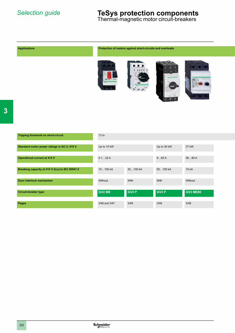
Applications Protection of motors against short-circuits and overloads
Tripping threshold on short-circuit 13 In
Standard motor power ratings in AC-3, 415 V Up to 15 kW Up to 30 kW 37 kW
Operational current at 415 V 0.1…32 A 9…65 A 56…80 A
Breaking capacity at 415 V (Icu) to IEC 60947-2 10…100 kA 35…100 kA 50…100 kA 15 kA
Door interlock mechanism Without With With Without
Circuit-breaker type GV2 ME GV2 P GV3 P GV3 ME80
Pages 3/46 and 3/47 3/48 3/48 3/48
TeSys protection componentsThermal-magnetic motor circuit-breakers
1
2
3
4
5
6
7
8
9
10
3/3
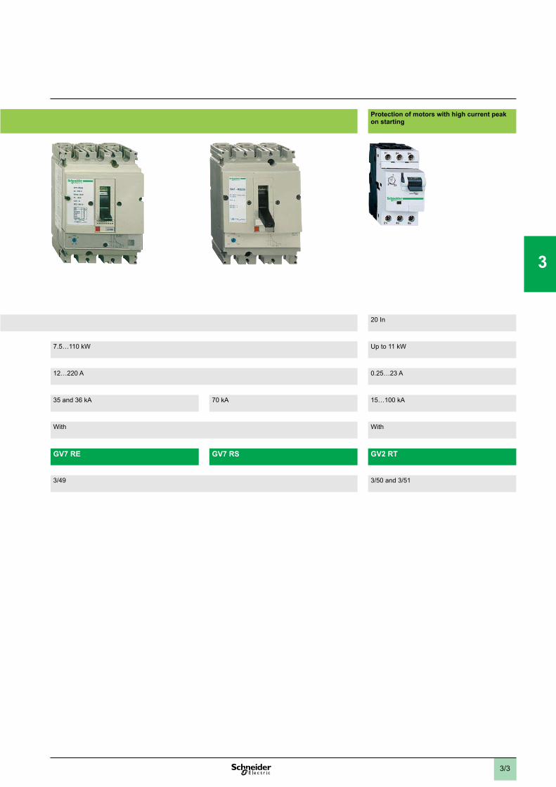
Protection of motors with high current peak on starting
20 In
7.5…110 kW Up to 11 kW
12…220 A 0.25…23 A
35 and 36 kA 70 kA 15…100 kA
With With
GV7 RE GV7 RS GV2 RT
3/49 3/50 and 3/51
1
2
3
4
5
6
7
8
9
10
3/4
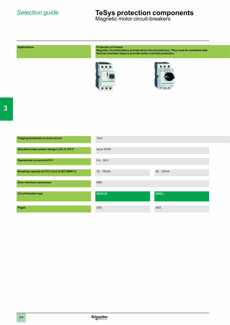
Applications Protection of motorsMagnetic circuit-breakers provide short-circuit protection. They must be combined with thermal overload relays to provide motor overload protection.
Tripping threshold on short-circuit 13 In
Standard motor power ratings in AC-3, 415 V Up to 15 kW
Operational current at 415 V 0.4…32 A
Breaking capacity at 415 V (Icu) to IEC 60947-2 10…100 kA 35…100 kA
Door interlock mechanism With
Circuit-breaker type GV2 LE GV2 L
Pages 3/52 3/53
Selection guide TeSys protection componentsMagnetic motor circuit-breakers
1
2
3
4
5
6
7
8
9
10
3/5
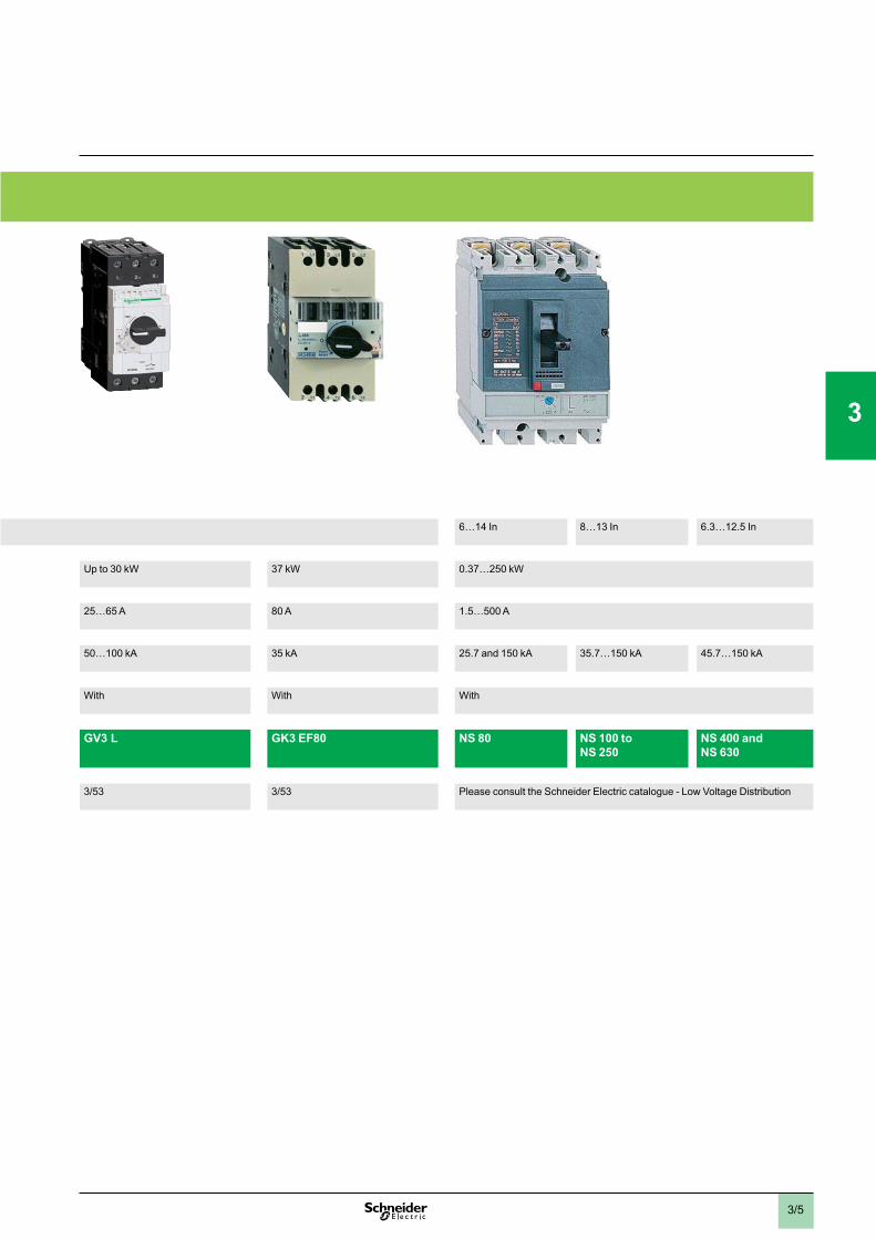
6…14 In 8…13 In 6.3…12.5 In
Up to 30 kW 37 kW 0.37…250 kW
25…65 A 80 A 1.5…500 A
50…100 kA 35 kA 25.7 and 150 kA 35.7…150 kA 45.7…150 kA
With With With
GV3 L GK3 EF80 NS 80 NS 100 to NS 250
NS 400 and NS 630
3/53 3/53 Please consult the Schneider Electric catalogue - Low Voltage Distribution
1
2
3
4
5
6
7
8
9
10
3/6
Presentation
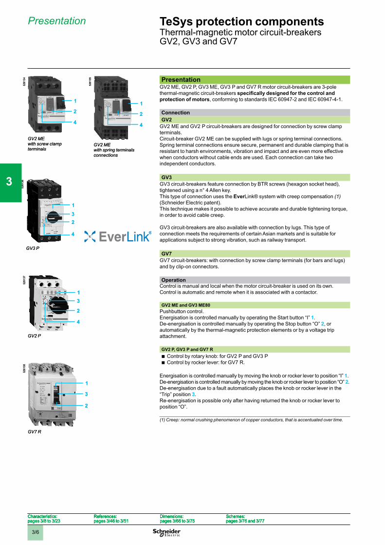
PresentationGV2 ME, GV2 P, GV3 ME, GV3 P and GV7 R motor circuit-breakers are 3-polethermal-magnetic circuit-breakersprotection of motors, conforming to standards IEC 60947-2 and IEC 60947-4-1. ConnectionGV2
GV2 ME and GV2 P circuit-breakers are designed for connection by screw clampterminals.Circuit-breaker GV2 ME can be supplied with lugs or spring terminal connections.Spring terminal connections ensure secure, permanent and durable clamping that isresistant to harsh environments, vibration and impact and are even more effectivewhen conductors without cable ends are used. Each connection can take twoindependent conductors.
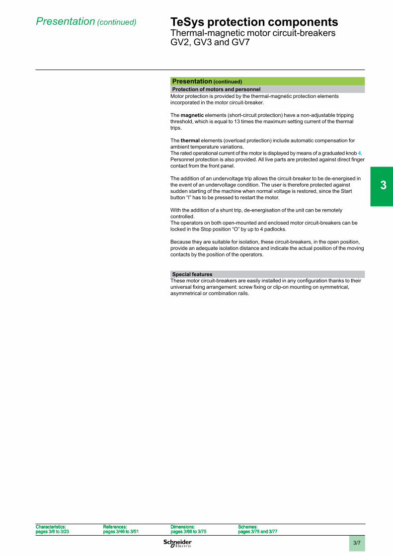
GV3GV3 circuit-breakers feature connection by BTR screws (hexagon socket head),tightened using a n° 4 Allen key.This type of connection uses the EverLink® system with creep compensation (1)(Schneider Electric patent).This technique makes it possible to achieve accurate and durable tightening torque,in order to avoid cable creep.
GV3 circuit-breakers are also available with connection by lugs. This type ofconnection meets the requirements of certain Asian markets and is suitable forapplications subject to strong vibration, such as railway transport.
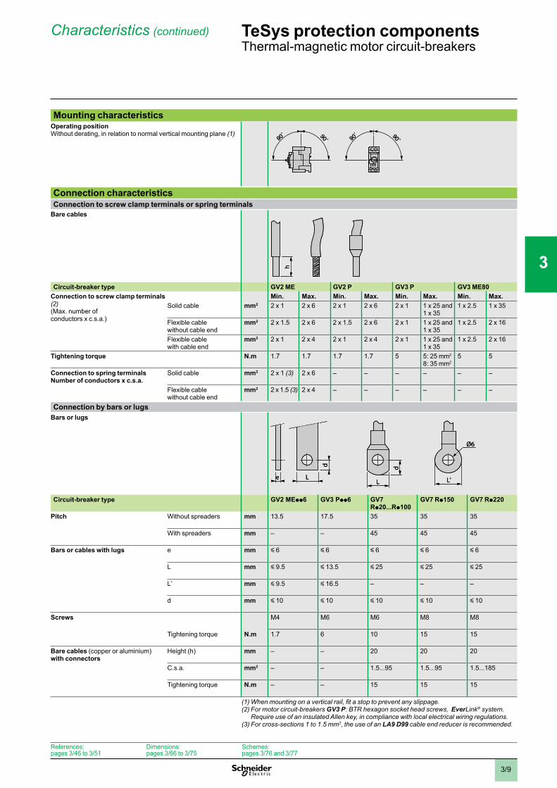
GV7GV7 circuit-breakers: with connection by screw clamp terminals (for bars and lugs)and by clip-on connectors. Operation
Control is manual and local when the motor circuit-breaker is used on its own.Control is automatic and remote when it is associated with a contactor. GV2 ME and GV3 ME80
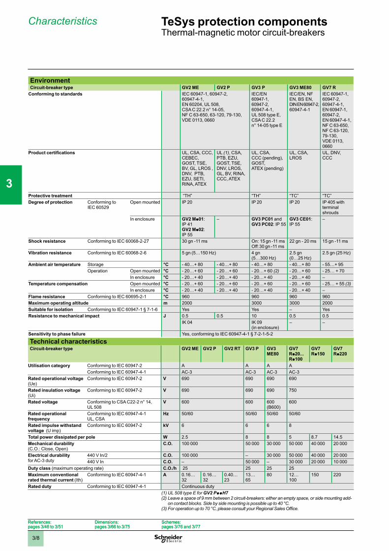
Pushbutton control.Energisation is controlled manually by operating the Start button “I” 1.De-energisation is controlled manually by operating the Stop button “O” 2, orautomatically by the thermal-magnetic protection elements or by a voltage tripattachment. GV2 P, GV3 P and GV7 R
Control by rotary knob: for GV2 P and GV3 PControl by rocker lever: for GV7 R.
bb
Energisation is controlled manually by moving the knob or rocker lever to position “I” 1.De-energisation is controlled manually by moving the knob or rocker lever to position “O” 2.De-energisation due to a fault automatically places the knob or rocker lever in the“Trip” position 3.Re-energisation is possible only after having returned the knob or rocker lever toposition “O”.
(1) Creep: normal crushing phenomenon of copper conductors, that is accentuated over time.
GV2 MEwith screw clamp terminals
5261
34
1
2
4
GV2 MEwith screw clamp terminals
5261
34
1
2
4
GV2 MEwith spring terminals connections
5261
35
1
2
4
GV2 MEwith spring terminals connections
5261
35
1
2
4
GV2 P
5261
37
13
4
2
GV2 P
5261
37
13
4
2
GV3 P
5261
36
132
4
GV3 P
5261
36
132
4
GV7 R
5261
38
1
3
2
GV7 R
5261
38
1
3
2
Characteristics:pages 3/8 to 3/23
References:pages 3/46 to 3/51
Dimensions:pages 3/66 to 3/75
Schemes:pages 3/76 and 3/77
Characteristics:pages 3/8 to 3/23
References:pages 3/46 to 3/51
Dimensions:pages 3/66 to 3/75
Schemes:pages 3/76 and 3/77
Characteristics:pages 3/8 to 3/23
References:pages 3/46 to 3/51
Dimensions:pages 3/66 to 3/75
Schemes:pages 3/76 and 3/77
Characteristics:pages 3/8 to 3/23
References:pages 3/46 to 3/51
Dimensions:pages 3/66 to 3/75
Schemes:pages 3/76 and 3/77
TeSys protection componentsThermal-magnetic motor circuit-breakersGV2, GV3 and GV7
1
2
3
4
5
6
7
8
9
10
3/7
Presentation (continued)
Presentation (continued)Protection of motors and personnel
Motor protection is provided by the thermal-magnetic protection elementsincorporated in the motor circuit-breaker.
The magnetic elements (short-circuit protection) have a non-adjustable trippingthreshold, which is equal to 13 times the maximum setting current of the thermaltrips.
The thermal elements (overload protection) include automatic compensation forambient temperature variations.The rated operational current of the motor is displayed by means of a graduated knob 4.
contact from the front panel.
The addition of an undervoltage trip allows the circuit-breaker to be de-energised inthe event of an undervoltage condition. The user is therefore protected againstsudden starting of the machine when normal voltage is restored, since the Startbutton “I” has to be pressed to restart the motor.
With the addition of a shunt trip, de-energisation of the unit can be remotelycontrolled.The operators on both open-mounted and enclosed motor circuit-breakers can belocked in the Stop position “O” by up to 4 padlocks.
Because they are suitable for isolation, these circuit-breakers, in the open position,provide an adequate isolation distance and indicate the actual position of the movingcontacts by the position of the operators.
Special features
asymmetrical or combination rails.
Characteristics:pages 3/8 to 3/23
References:pages 3/46 to 3/51
Dimensions:pages 3/66 to 3/75
Schemes:pages 3/76 and 3/77
Characteristics:pages 3/8 to 3/23
References:pages 3/46 to 3/51
Dimensions:pages 3/66 to 3/75
Schemes:pages 3/76 and 3/77
Characteristics:pages 3/8 to 3/23
References:pages 3/46 to 3/51
Dimensions:pages 3/66 to 3/75
Schemes:pages 3/76 and 3/77
Characteristics:pages 3/8 to 3/23
References:pages 3/46 to 3/51
Dimensions:pages 3/66 to 3/75
Schemes:pages 3/76 and 3/77
TeSys protection componentsThermal-magnetic motor circuit-breakersGV2, GV3 and GV7
1
2
3
4
5
6
7
8
9
10
3/8
Characteristics
EnvironmentCircuit-breaker type GV2 ME GV2 P GV3 P GV3 ME80 GV7 R
Conforming to standards IEC 60947-1, 60947-2,60947-4-1,EN 60204, UL 508,CSA C 22.2 n° 14-05,NF C 63-650, 63-120, 79-130,VDE 0113, 0660
IEC/EN60947-1,60947-2,60947-4-1,UL 508 type E,CSA C 22.2n° 14-05 type E
IEC/EN, NFEN, BS EN,DINEN60947-2,60947-4-1
IEC 60947-1,60947-2,60947-4-1,EN 60947-1,60947-2,EN 60947-4-1,NF C 63-650,NF C 63-120,79-130,VDE 0113,0660
UL, CSA, CCC,CEBEC,GOST, TSE,BV, GL, LROS ,DNV, PTB,EZU, SETI,RINA, ATEX
UL (1), CSA, PTB, EZU,GOST, TSE,DNV, LROS,GL, BV, RINA,CCC, ATEX
UL, CSA,CCC (pending),GOST,ATEX (pending)
UL, CSA, LROS
UL, DNV, CCC
Protective treatment “TH” “TH” “TC” “TC”Degree of protection Conforming to
IEC 60529Open mounted IP 20 IP 20 IP 20 IP 405 with
terminalshrouds
In enclosure GV2 Mp01:IP 41GV2 Mp02:IP 55
– GV3 PC01 andGV3 PC02: IP 55
GV3 CE01:IP 55
–
Shock resistance Conforming to IEC 60068-2-27 30 gn -11 ms On: 15 gn -11 msOff:30 gn -11 ms
22 gn - 20 ms 15 gn -11 ms
Vibration resistance Conforming to IEC 60068-2-6 5 gn (5…150 Hz) 4 gn(5…300 Hz)
2.5 gn(0…25 Hz)
2.5 gn (25 Hz)
Ambient air temperature Storage °C - 40…+ 80 - 40…+ 80 - 40…+ 80 - 40…+ 80 - 55…+ 95Operation Open mounted °C - 20…+ 60 - 20…+ 60 - 20…+ 60 (2) - 20…+ 60 - 25… + 70
In enclosure °C - 20…+ 40 - 20…+ 40 - 20…+ 40 - 20…+ 40 –Temperature compensation Open mounted °C - 20…+ 60 - 20…+ 60 - 20…+ 60 - 20…+ 60 - 25… + 55 (3)
In enclosure °C - 20…+ 40 - 20…+ 40 - 20…+ 40 - 20…+ 40 –Flame resistance Conforming to IEC 60695-2-1 °C 960 960 960 960Maximum operating altitude m 2000 3000 3000 2000Suitable for isolation Conforming to IEC 60947-1 § 7-1-6 Yes Yes – YesResistance to mechanical impact J 0.5 0.5 10 0.5 0.5
IK 04 IK 09(in enclosure)
– –
Sensitivity to phase failure Yes, conforming to IEC 60947-4-1 § 7-2-1-5-2
Technical characteristicsCircuit-breaker type GV2 ME GV2 P GV2 RT GV3 P GV3
ME80GV7Rp20... Rp100
GV7Rp150
GV7Rp220
Utilisation category Conforming to IEC 60947-2 A A A AConforming to IEC 60947-4-1 AC-3 AC-3 AC-3 AC-3
Rated operational voltage(Ue)
Conforming to IEC 60947-2 V 690 690 690 690
Rated insulation voltage (Ui)
Conforming to IEC 60947-2 V 690 690 690 750
Rated voltage Conforming to CSA C22-2 n° 14,UL 508
V 600 600 600(B600)
600
Rated operational frequency
Conforming to IEC 60947-4-1UL, CSA
Hz 50/60 50/60 50/60 50/60
Rated impulse withstand voltage (U imp)
Conforming to IEC 60947-2 kV 6 6 6 8
Total power dissipated per pole W 2.5 8 8 5 8.7 14.5Mechanical durability(C.O.: Close, Open)
C.O. 100 000 50 000 30 000 50 000 40 000 20 000
Electrical durabilityfor AC-3 duty
440 V In/2 C.O. 100 000 – 30 000 50 000 40 000 20 000440 V In C.O. – 50 000 – 30 000 20 000 10 000
Duty class (maximum operating rate) C.O./h 25 25 25 25Maximum conventional rated thermal current (Ith)
Conforming to IEC 60947-4-1 A 0.16…32
0.16…32
0.40…23
13…65
80 12…100
150 220
Rated duty Conforming to IEC 60947-4-1 Continuous duty(1) UL 508 type E for GV2 PppH7(2) Leave a space of 9 mm between 2 circuit-breakers: either an empty space, or side mounting add-
on contact blocks. Side by side mounting is possible up to 40 °C.
TeSys protection componentsThermal-magnetic motor circuit-breakers
References:pages 3/46 to 3/51
Dimensions:pages 3/66 to 3/75
Schemes:pages 3/76 and 3/77
References:pages 3/46 to 3/51
Dimensions:pages 3/66 to 3/75
Schemes:pages 3/76 and 3/77
1
2
3
4
5
6
7
8
9
10
3/9
Characteristics (continued)
Mounting characteristicsOperating positionWithout derating, in relation to normal vertical mounting plane (1)
Connection characteristicsConnection to screw clamp terminals or spring terminals
Bare cables
Circuit-breaker type GV2 ME GV2 P GV3 P GV3 ME80Connection to screw clamp terminals (2)(Max. number ofconductors x c.s.a.)
Min. Max. Min. Max. Min. Max. Min. Max.Solid cable mm2 2 x 1 2 x 6 2 x 1 2 x 6 2 x 1 1 x 25 and
1 x 351 x 2.5 1 x 35
Flexible cablewithout cable end
mm2 2 x 1.5 2 x 6 2 x 1.5 2 x 6 2 x 1 1 x 25 and1 x 35
1 x 2.5 2 x 16
Flexible cablewith cable end
mm2 2 x 1 2 x 4 2 x 1 2 x 4 2 x 1 1 x 25 and1 x 35
1 x 2.5 2 x 16
Tightening torque N.m 1.7 1.7 1.7 1.7 5 5: 25 mm2
8: 35 mm25 5
Connection to spring terminalsNumber of conductors x c.s.a.
Solid cable mm2 2 x 1 (3) 2 x 6 – – – – – –
Flexible cablewithout cable end
mm2 2 x 1.5 (3) 2 x 4 – – – – – –
Connection by bars or lugsBars or lugs
Circuit-breaker type GV2 MEpp6 GV3 Ppp6 GV7Rp20...Rp100
GV7 Rp150 GV7 Rp220
Pitch Without spreaders mm 13.5 17.5 35 35 35
With spreaders mm – – 45 45 45
Bars or cables with lugs e mm y 6 y 6 y 6 y 6 y 6
L mm y 9.5 y 13.5 y 25 y 25 y 25
L’ mm y 9.5 y 16.5 – – –
d mm y 10 y 10 y 10 y 10 y 10
Screws M4 M6 M6 M8 M8
Tightening torque N.m 1.7 6 10 15 15
Bare cables (copper or aluminium)with connectors
Height (h) mm – – 20 20 20
C.s.a. mm2 – – 1.5...95 1.5...95 1.5...185
Tightening torque N.m – – 15 15 15
(2) For motor circuit-breakers GV3 P: BTR hexagon socket head screws, EverLink® system.Require use of an insulated Allen key, in compliance with local electrical wiring regulations.
(3) For cross-sections 1 to 1.5 mm2, the use of an LA9 D99 cable end reducer is recommended.
90˚ 90˚90
˚ 90˚ 90˚ 90˚90
˚ 90˚
hh
e
d
L
d
L L'
Ø6
e
d
L
d
L L'
Ø6
TeSys protection componentsThermal-magnetic motor circuit-breakers
References:pages 3/46 to 3/51
Dimensions:pages 3/66 to 3/75
Schemes:pages 3/76 and 3/77
1
2
3
4
5
6
7
8
9
10
3/10
Characteristics
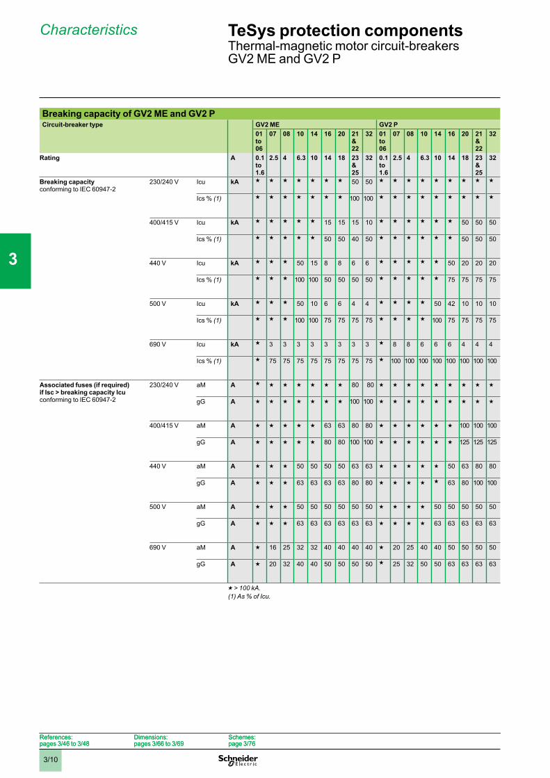
Breaking capacity of GV2 ME and GV2 PCircuit-breaker type GV2 ME GV2 P
01to06
07 08 10 14 16 20 21&22
32 01to06
07 08 10 14 16 20 21&22
32
Rating A 0.1to1.6
2.5 4 6.3 10 14 18 23&25
32 0.1to1.6
2.5 4 6.3 10 14 18 23&25
32
Breaking capacityconforming to IEC 60947-2
230/240 V Icu kA g g g g g g g 50 50 g g g g g g g g g
Ics % (1) g g g g g g g 100 100 g g g g g g g g g
400/415 V Icu kA g g g g g 15 15 15 10 g g g g g g 50 50 50
Ics % (1) g g g g g 50 50 40 50 g g g g g g 50 50 50
440 V Icu kA g g g 50 15 8 8 6 6 g g g g g 50 20 20 20
Ics % (1) g g g 100 100 50 50 50 50 g g g g g 75 75 75 75
500 V Icu kA g g g 50 10 6 6 4 4 g g g g 50 42 10 10 10
Ics % (1) g g g 100 100 75 75 75 75 g g g g 100 75 75 75 75
690 V Icu kA g 3 3 3 3 3 3 3 3 g 8 8 6 6 6 4 4 4
Ics % (1) g 75 75 75 75 75 75 75 75 g 100 100 100 100 100 100 100 100
Associated fuses (if required) if Isc > breaking capacity Icu conforming to IEC 60947-2
230/240 V aM A g g g g g g g 80 80 g g g g g g g g g
gG A g g g g g g g 100 100 g g g g g g g g g
400/415 V aM A g g g g g 63 63 80 80 g g g g g g 100 100 100
gG A g g g g g 80 80 100 100 g g g g g g 125 125 125
440 V aM A g g g 50 50 50 50 63 63 g g g g g 50 63 80 80
gG A g g g 63 63 63 63 80 80 g g g g g 63 80 100 100
500 V aM A g g g 50 50 50 50 50 50 g g g g 50 50 50 50 50
gG A g g g 63 63 63 63 63 63 g g g g 63 63 63 63 63
690 V aM A g 16 25 32 32 40 40 40 40 g 20 25 40 40 50 50 50 50
gG A g 20 32 40 40 50 50 50 50 g 25 32 50 50 63 63 63 63
g > 100 kA.(1) As % of Icu.
TeSys protection componentsThermal-magnetic motor circuit-breakersGV2 ME and GV2 P
References:pages 3/46 to 3/48
Dimensions:pages 3/66 to 3/69
Schemes:page 3/76
References:pages 3/46 to 3/48
Dimensions:pages 3/66 to 3/69
Schemes:page 3/76
1
2
3
4
5
6
7
8
9
10
3/11
Characteristics (continued)
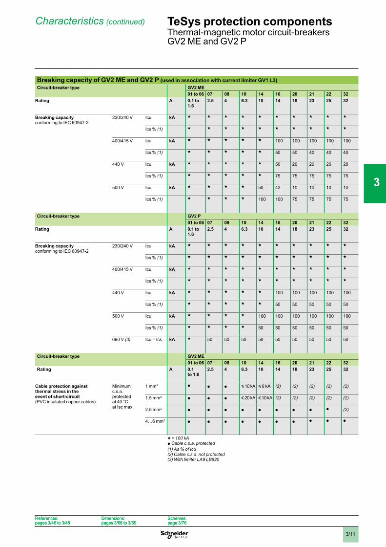
Breaking capacity of GV2 ME and GV2 P (used in association with current limiter GV1 L3)Circuit-breaker type GV2 ME
01 to 06 07 08 10 14 16 20 21 22 32Rating A 0.1 to
1.62.5 4 6.3 10 14 18 23 25 32
Breaking capacityconforming to IEC 60947-2
230/240 V Icu kA g g g g g g g g g g
Ics % (1) g g g g g g g g g g
400/415 V Icu kA g g g g g 100 100 100 100 100
Ics % (1) g g g g g 50 50 40 40 40
440 V Icu kA g g g g g 50 20 20 20 20
Ics % (1) g g g g g 75 75 75 75 75
500 V Icu kA g g g g 50 42 10 10 10 10
Ics % (1) g g g g 100 100 75 75 75 75
Circuit-breaker type GV2 P01 to 06 07 08 10 14 16 20 21 22 32
Rating A 0.1 to 1.6
2.5 4 6.3 10 14 18 23 25 32
Breaking capacityconforming to IEC 60947-2
230/240 V Icu kA g g g g g g g g g g
Ics % (1) g g g g g g g g g g
400/415 V Icu kA g g g g g g g g g g
Ics % (1) g g g g g g g g g g
440 V Icu kA g g g g g 100 100 100 100 100
Ics % (1) g g g g g 50 50 50 50 50
500 V Icu kA g g g g 100 100 100 100 100 100
Ics % (1) g g g g 50 50 50 50 50 50
690 V (3) Icu = Ics kA g 50 50 50 50 50 50 50 50 50
Circuit-breaker type GV2 ME01 to 06 07 08 10 14 16 20 21 22 32
Rating A 0.1to 1.6
2.5 4 6.3 10 14 18 23 25 32
Cable protection against thermal stress in the event of short-circuit(PVC insulated copper cables)
Minimumc.s.a.protectedat 40 °Cat Isc max.
1 mm2 p p p y10 kA y 6 kA (2) (2) (2) (2) (2)
1.5 mm2 p p p y20 kA y10 kA (2) (2) (2) (2) (2)
2.5 mm2 p p p p p p p p p (2)
4…6 mm2 p p p p p p p p p p
g > 100 kAp Cable c.s.a. protected(1) As % of Icu(2) Cable c.s.a. not protected(3) With limiter LA9 LB920
TeSys protection componentsThermal-magnetic motor circuit-breakersGV2 ME and GV2 P
References:pages 3/46 to 3/48
Dimensions:pages 3/66 to 3/69
Schemes:page 3/76
References:pages 3/46 to 3/48
Dimensions:pages 3/66 to 3/69
Schemes:page 3/76
1
2
3
4
5
6
7
8
9
10
3/12
Characteristics
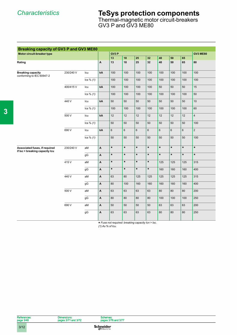
Breaking capacity of GV3 P and GV3 ME80Motor circuit-breaker type GV3 P GV3 ME80
13 18 25 32 40 50 65Rating A 13 18 25 32 40 50 65 80
Breaking capacityconforming to IEC 60947-2
230/240 V Icu kA 100 100 100 100 100 100 100 100
Ics % (1) 100 100 100 100 100 100 100 100
400/415 V Icu kA 100 100 100 100 50 50 50 15
Ics % (1) 100 100 100 100 100 100 100 50
440 V Icu kA 50 50 50 50 50 50 50 10
Ics % (1) 100 100 100 100 100 100 100 60
500 V Icu kA 12 12 12 12 12 12 12 4
Ics % (1) 50 50 50 50 50 50 50 100
690 V Icu kA 6 6 6 6 6 6 6 2
Ics % (1) 50 50 50 50 50 50 50 100
Associated fuses, if required if lsc > breaking capacity Icu
230/240 V aM A g g g g g g g g
gG A g g g g g g g g
415 V aM A g g g g 125 125 125 315
gG A g g g g 160 160 160 400
440 V aM A 63 80 125 125 125 125 125 315
gG A 80 100 160 160 160 160 160 400
500 V aM A 63 63 63 63 80 80 80 200
gG A 80 80 80 80 100 100 100 250
690 V aM A 50 50 50 50 63 63 63 200
gG A 63 63 63 63 80 80 80 250
g Fuse not required: breaking capacity Icn > Isc.(1) As % of Icu.
TeSys protection componentsThermal-magnetic motor circuit-breakersGV3 P and GV3 ME80
References:page 3/48
Dimensions:pages 3/71 and 3/72
Schemes:pages 3/76 and 3/77
References:page 3/48
Dimensions:pages 3/71 and 3/72
Schemes:pages 3/76 and 3/77
1
2
3
4
5
6
7
8
9
10
3/13
Characteristics
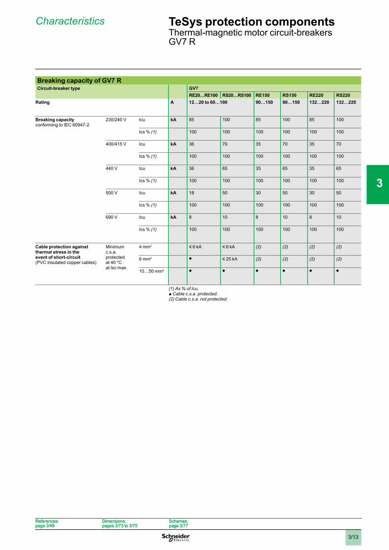
Breaking capacity of GV7 RCircuit-breaker type GV7
RE20…RE100 RS20…RS100 RE150 RS150 RE220 RS220Rating A 12…20 to 60…100 90…150 90…150 132…220 132…220
Breaking capacityconforming to IEC 60947-2
230/240 V lcu kA 85 100 85 100 85 100
Ics % (1) 100 100 100 100 100 100
400/415 V Icu kA 36 70 35 70 35 70
Ics % (1) 100 100 100 100 100 100
440 V Icu kA 36 65 35 65 35 65
Ics % (1) 100 100 100 100 100 100
500 V Icu kA 18 50 30 50 30 50
Ics % (1) 100 100 100 100 100 100
690 V Icu kA 8 10 8 10 8 10
Ics % (1) 100 100 100 100 100 100
Cable protection against thermal stress in the event of short-circuit(PVC insulated copper cables)
Minimumc.s.a.protectedat 40 °Cat Isc max.
4 mm2 y 6 kA y 6 kA (2) (2) (2) (2)
6 mm2 p y 25 kA (2) (2) (2) (2)
10…50 mm2 p p p p p p
(1) As % of Icu.p Cable c.s.a. protected.(2) Cable c.s.a. not protected.
TeSys protection componentsThermal-magnetic motor circuit-breakersGV7 R
References:page 3/49
Dimensions:pages 3/73 to 3/75
Schemes:page 3/77
References:page 3/49
Dimensions:pages 3/73 to 3/75
Schemes:page 3/77
1
2
3
4
5
6
7
8
9
10
3/14
Characteristics
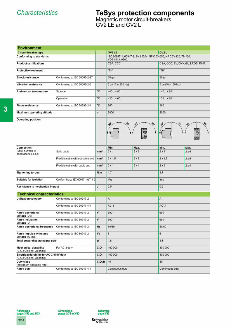
EnvironmentCircuit-breaker type GV2 LE GV2 L
Conforming to standards IEC 60947-1, 60947-2, EN 60204, NF C 63-650, NF C63-120, 79-130,VDE 0113, 0660.CSA, CCC CSA, CCC, BV, DNV, GL, LROS, RINA
Protective treatment “TH” “TH”
Shock resistance Conforming to IEC 60068-2-27 30 gn 30 gn
Vibration resistance Conforming to IEC 60068-2-6 5 gn (5 to 150 Hz) 5 gn (5 to 150 Hz)
Ambient air temperature Storage °C - 40…+ 80 - 40…+ 80
Operation °C - 20…+ 60 - 20…+ 60
Flame resistance Conforming to IEC 60695-2-1 °C 960 960
Maximum operating altitude m 2000 2000
Operating position
Connection(Max. number ofconductors x c.s.a)
Min. Max. Min. Max.Solid cable mm2 2 x 1 2 x 6 2 x 1 2 x 6
Flexible cable without cable end mm2 2 x 1.5 2 x 6 2 x 1.5 2 x 6
Flexible cable with cable end mm2 2 x 1 2 x 4 2 x 1 2 x 4
Tightening torque N.m 1.7 1.7
Suitable for isolation Conforming to IEC 60947-1 § 7-1-6 Yes Yes
Resistance to mechanical impact J 0.5 0.5
Technical characteristicsUtilisation category Conforming to IEC 60947-2 A A
Conforming to IEC 60947-4-1 AC-3 AC-3
Rated operational voltage (Ue)
Conforming to IEC 60947-2 V 690 690
Rated insulation voltage (Ui)
Conforming to IEC 60947-2 V 690 690
Rated operational frequency Conforming to IEC 60947-2 Hz 50/60 50/60
Rated impulse withstand voltage (U imp)
Conforming to IEC 60947-2 kV 6 6
Total power dissipated per pole W 1.8 1.8
Mechanical durability(C.O.: Closing, Opening)
For AC-3 duty C.O. 100 000 100 000
Electrical durability for AC-3/415V duty(C.O.: Closing, Opening)
C.O. 100 000 100 000
Duty class(maximum operating rate)
C.O./h 40 40
Rated duty Conforming to IEC 60947-4-1 Continuous duty Continuous duty
References:pages 3/52 and 3/53
Dimensions:pages 3/78 to 3/80
Schemes:page 3/83
References:pages 3/52 and 3/53
Dimensions:pages 3/78 to 3/80
Schemes:page 3/83
References:pages 3/52 and 3/53
Dimensions:pages 3/78 to 3/80
Schemes:page 3/83
References:pages 3/52 and 3/53
Dimensions:pages 3/78 to 3/80
Schemes:page 3/83
TeSys protection componentsMagnetic motor circuit-breakersGV2 LE and GV2 L
1
2
3
4
5
6
7
8
9
10
3/15
Characteristics (continued)
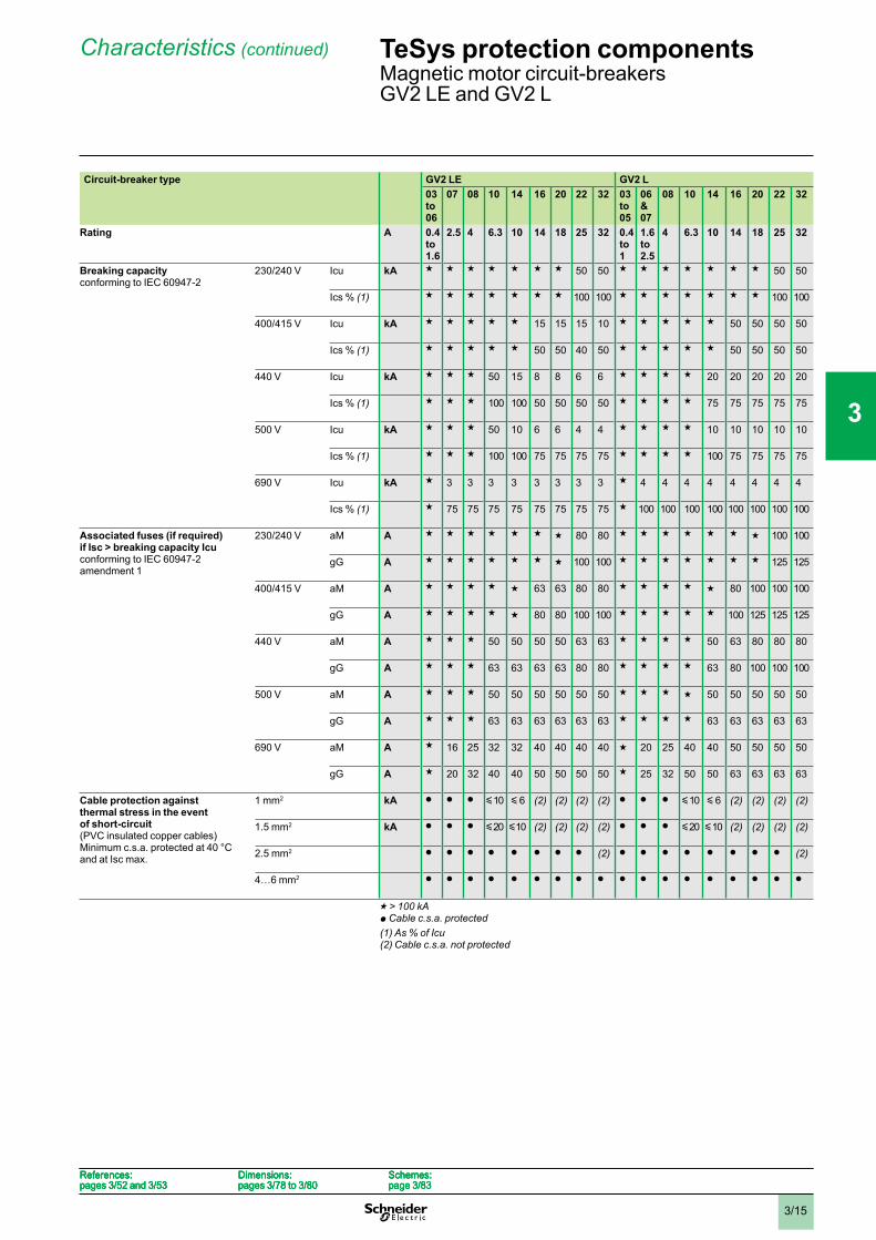
Circuit-breaker type GV2 LE GV2 L03to06
07 08 10 14 16 20 22 32 03to05
06&07
08 10 14 16 20 22 32
Rating A 0.4to1.6
2.5 4 6.3 10 14 18 25 32 0.4to1
1.6to2.5
4 6.3 10 14 18 25 32
Breaking capacityconforming to IEC 60947-2
230/240 V Icu kA g g g g g g g 50 50 g g g g g g g 50 50
Ics % (1) g g g g g g g 100 100 g g g g g g g 100 100
400/415 V Icu kA g g g g g 15 15 15 10 g g g g g 50 50 50 50
Ics % (1) g g g g g 50 50 40 50 g g g g g 50 50 50 50
440 V Icu kA g g g 50 15 8 8 6 6 g g g g 20 20 20 20 20
Ics % (1) g g g 100 100 50 50 50 50 g g g g 75 75 75 75 75
500 V Icu kA g g g 50 10 6 6 4 4 g g g g 10 10 10 10 10
Ics % (1) g g g 100 100 75 75 75 75 g g g g 100 75 75 75 75
690 V Icu kA g 3 3 3 3 3 3 3 3 g 4 4 4 4 4 4 4 4
Ics % (1) g 75 75 75 75 75 75 75 75 g 100 100 100 100 100 100 100 100
Associated fuses (if required)if Isc > breaking capacity Icu conforming to IEC 60947-2amendment 1
230/240 V aM A g g g g g g g 80 80 g g g g g g g 100 100
gG A g g g g g g g 100 100 g g g g g g g 125 125
400/415 V aM A g g g g g 63 63 80 80 g g g g g 80 100 100 100
gG A g g g g g 80 80 100 100 g g g g g 100 125 125 125
440 V aM A g g g 50 50 50 50 63 63 g g g g 50 63 80 80 80
gG A g g g 63 63 63 63 80 80 g g g g 63 80 100 100 100
500 V aM A g g g 50 50 50 50 50 50 g g g g 50 50 50 50 50
gG A g g g 63 63 63 63 63 63 g g g g 63 63 63 63 63
690 V aM A g 16 25 32 32 40 40 40 40 g 20 25 40 40 50 50 50 50
gG A g 20 32 40 40 50 50 50 50 g 25 32 50 50 63 63 63 63
Cable protection against thermal stress in the event of short-circuit(PVC insulated copper cables)Minimum c.s.a. protected at 40 °Cand at Isc max.
1 mm2 kA p p p y10 y 6 (2) (2) (2) (2) p p p y10 y 6 (2) (2) (2) (2)
1.5 mm2 kA p p p y20 y10 (2) (2) (2) (2) p p p y20 y10 (2) (2) (2) (2)
2.5 mm2 p p p p p p p p (2) p p p p p p p p (2)
4…6 mm2 p p p p p p p p p p p p p p p p p p
g > 100 kAp Cable c.s.a. protected(1) As % of Icu(2) Cable c.s.a. not protected
References:pages 3/52 and 3/53
Dimensions:pages 3/78 to 3/80
Schemes:page 3/83
References:pages 3/52 and 3/53
Dimensions:pages 3/78 to 3/80
Schemes:page 3/83
References:pages 3/52 and 3/53
Dimensions:pages 3/78 to 3/80
Schemes:page 3/83
References:pages 3/52 and 3/53
Dimensions:pages 3/78 to 3/80
Schemes:page 3/83
TeSys protection componentsMagnetic motor circuit-breakersGV2 LE and GV2 L
1
2
3
4
5
6
7
8
9
10
3/16
Characteristics
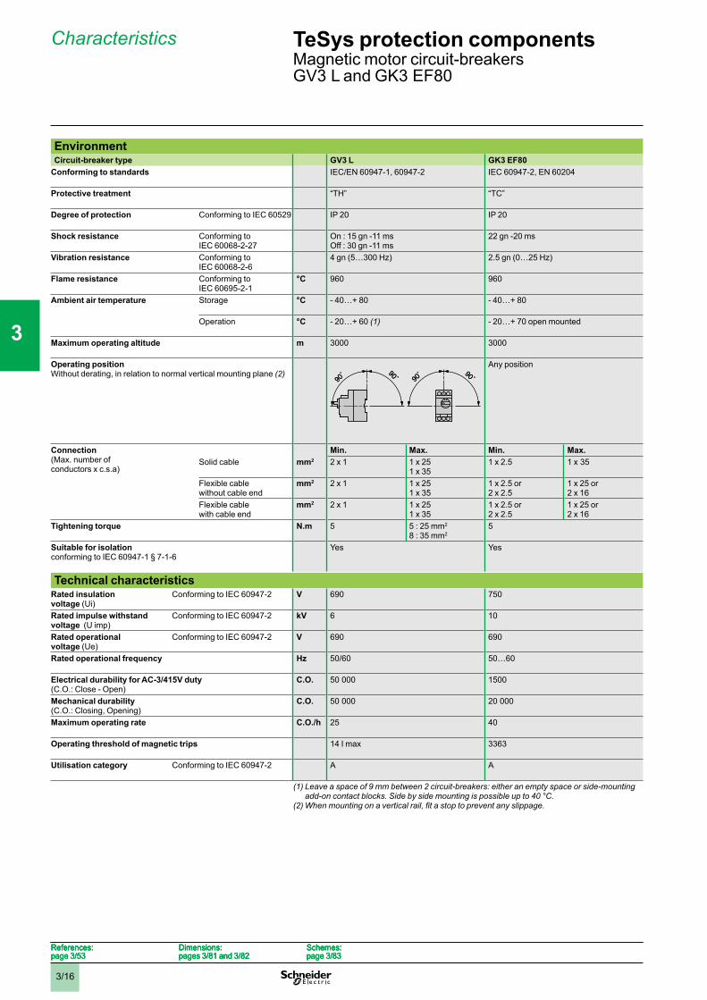
EnvironmentCircuit-breaker type GV3 L GK3 EF80
Conforming to standards IEC/EN 60947-1, 60947-2 IEC 60947-2, EN 60204
Protective treatment “TH” “TC”
Degree of protection Conforming to IEC 60529 IP 20 IP 20
Shock resistance Conforming toIEC 60068-2-27
On : 15 gn -11 msOff : 30 gn -11 ms
22 gn -20 ms
Vibration resistance Conforming toIEC 60068-2-6
4 gn (5…300 Hz) 2.5 gn (0…25 Hz)
Flame resistance Conforming toIEC 60695-2-1
°C 960 960
Ambient air temperature Storage °C - 40…+ 80 - 40…+ 80
Operation °C - 20…+ 60 (1) - 20…+ 70 open mounted
Maximum operating altitude m 3000 3000
Operating positionWithout derating, in relation to normal vertical mounting plane (2)
Any position
Connection(Max. number ofconductors x c.s.a)
Min. Max. Min. Max.Solid cable mm2 2 x 1 1 x 25
1 x 351 x 2.5 1 x 35
Flexible cablewithout cable end
mm2 2 x 1 1 x 251 x 35
1 x 2.5 or2 x 2.5
1 x 25 or2 x 16
Flexible cablewith cable end
mm2 2 x 1 1 x 251 x 35
1 x 2.5 or2 x 2.5
1 x 25 or2 x 16
Tightening torque N.m 5 5 : 25 mm2
8 : 35 mm25
Suitable for isolationconforming to IEC 60947-1 § 7-1-6
Yes Yes
Technical characteristicsRated insulationvoltage (Ui)
Conforming to IEC 60947-2 V 690 750
Rated impulse withstand voltage (U imp)
Conforming to IEC 60947-2 kV 6 10
Rated operationalvoltage (Ue)
Conforming to IEC 60947-2 V 690 690
Rated operational frequency Hz 50/60 50…60
Electrical durability for AC-3/415V duty(C.O.: Close - Open)
C.O. 50 000 1500
Mechanical durability(C.O.: Closing, Opening)
C.O. 50 000 20 000
Maximum operating rate C.O./h 25 40
Operating threshold of magnetic trips 14 I max 3363
Utilisation category Conforming to IEC 60947-2 A A
(1) Leave a space of 9 mm between 2 circuit-breakers: either an empty space or side-mounting add-on contact blocks. Side by side mounting is possible up to 40 °C.
References:page 3/53
Dimensions:pages 3/81 and 3/82
Schemes:page 3/83
References:page 3/53
Dimensions:pages 3/81 and 3/82
Schemes:page 3/83
References:page 3/53
Dimensions:pages 3/81 and 3/82
Schemes:page 3/83
References:page 3/53
Dimensions:pages 3/81 and 3/82
Schemes:page 3/83
TeSys protection componentsMagnetic motor circuit-breakersGV3 L and GK3 EF80
1
2
3
4
5
6
7
8
9
10
3/17
Characteristics (continued)
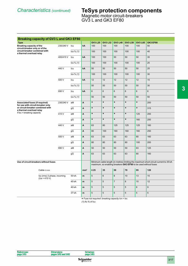
Breaking capacity of GV3 L and GK3 EF80Type GV3 L25 GV3 L32 GV3 L40 GV3 L50 GV3 L65 GK3 EF80
Breaking capacity of the circuit-breaker only or of the circuit-breaker combined with a thermal overload relay
230/240 V Icu kA 100 100 100 100 100 50
Ics % (1) 100 100 100 100 100 40
400/415 V Icu kA 100 100 50 50 50 35
Ics % (1) 100 100 100 100 100 25
440 V Icu kA 50 50 50 50 50 25
Ics % (1) 100 100 100 100 100 30
500 V Icu kA 12 12 12 12 12 15
Ics % (1) 50 50 50 50 50 30
690 V Icu kA 6 6 6 6 6 6
Ics % (1) 50 50 50 50 50 50
Associated fuses (if required) for use with circuit-breaker only or circuit-breaker combined with a thermal overload relayif lsc > breaking capacity
230/240 V aM A g g g g g 200
gG A g g g g g 315
415 V aM A g g g g 125 200
gG A g g g g 160 250
440 V aM A 63 80 125 125 125 160
gG A 80 100 160 160 160 250
500 V aM A 63 63 63 63 80 160
gG A 80 80 80 80 100 200
690 V aM A 50 50 50 50 63 125
gG A 63 63 63 63 80 160
Use of circuit-breakers without fuses Minimum cable length (in metres) limiting the maximum short-circuit current to 35 kAmaximum, so enabling breakers GK3 EF80 to be used without fuses
Cable c.s.a. mm2 y 25 35 50 70 95 120
Isc (rms) 3-phase, incoming(Ue = 415 V)
50 kA m 5 6 8 10 13 15
45 kA m 5 5 7 8 10 12
40 kA m 5 5 5 5 8 9
37 kA m 5 5 5 5 5 5
g Fuse not required: breaking capacity Icn > Isc.(1) As % of Icu
References:page 3/53
Dimensions:pages 3/82 and 3/82
Schemes:page 3/83
References:page 3/53
Dimensions:pages 3/82 and 3/82
Schemes:page 3/83
References:page 3/53
Dimensions:pages 3/82 and 3/82
Schemes:page 3/83
References:page 3/53
Dimensions:pages 3/82 and 3/82
Schemes:page 3/83
TeSys protection componentsMagnetic motor circuit-breakersGV3 L and GK3 EF80
1
2
3
4
5
6
7
8
9
10
3/18
Characteristics
0 1
FF
FO
O
O
F
F
F
F
O
F
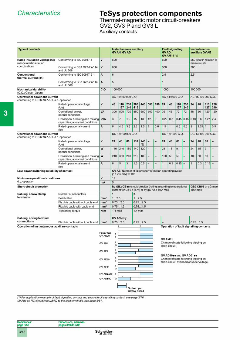
Type of contacts Instantaneous auxiliaryGV AN, GV AD
Fault signalling GV AD,GV AM11 (1)
Instantaneousauxiliary GV AE
Rated insulation voltage (Ui)(associated insulationcoordination)
Conforming to IEC 60947-1 V 690 690 250 (690 in relation tomain circuit)
Conforming to CSA C22-2 n° 14and UL 508
V 600 300 300
Conventionalthermal current (Ith)
Conforming to IEC 60947-5-1 A 6 2.5 2.5
Conforming to CSA C22-2 n° 14and UL 508
A 5 1 1
Mechanical durability(C.O.: Close - Open)
C.O. 100 000 1000 100 000
Operational power and currentconforming to IEC 60947-5-1. a.c. operation
AC-15/100 000 C.O. AC-14/1000 C.O. AC-15/100 000 C.O.
Rated operational voltage(Ue)
V 48 110 127
230240
380415
440 500 690 24 48 110 127
230240
24 48 110 127
230240
Operational power,normal conditions
VA 300 500 720 850 650 500 400 36 48 72 72 48 60 120 120
Occasional breaking and makingcapacities, abnormal conditions
kVA 3 7 13 15 13 12 9 0.22 0.3 0.45 0.45 0.48 0.6 1.27 2.4
Rated operational current(Ie)
A 6 4.5 3.3 2.2 1.5 1 0.6 1.5 1 0.5 0.3 2 1.25 1 0.5
Operational power and currentconforming to IEC 60947-5-1. d.c. operation
DC-13/100 000 C.O. DC-13/1000 C.O. DC-13/100 000 C.O.
Rated operational voltage(Ue)
V 24 48 60 110 240(2)
– – 24 48 60 – 24 48 60 –
Operational power,normal conditions
W 140 240 180 140 120 – – 24 15 9 – 24 15 9 –
Occasional breaking and makingcapacities, abnormal conditions
W 240 360 240 210 180 – – 100 50 50 – 100 50 50 –
Rated operational current(Ie)
A 6 5 3 1.3 0.5 – – 1 0.3 0.15 – 1 0.3 0.15 –
Low power switching reliability of contact GV AE: Number of failures for “n” million operating cycles(17 V-5 mA): = 10-6
Minimum operational conditionsd.c. operation
V 17mA 5
Short-circuit protection By GB2 CBpp circuit-breaker (rating according to operationalcurrent for Ue y 415 V) or by gG fuse 10 A max
GB2 CB06 or gG fuse10 A max
Cabling, screw clamp terminals
Number of conductors 1 2Solid cable mm2 1…2.5 1…2.5Flexible cable without cable end mm2 0.75…2.5 0.75…2.5Flexible cable with cable end mm2 0.75…1.5 0.75…1.5Tightening torque N.m 1.4 max 1.4 max
Cabling, spring terminal connections
GV AN onlyFlexible cable without cable end mm2 0.75…2.5 0.75…2.5 – 0.75…1.5
Operation of instantaneous auxiliary contacts Operation of fault signalling contacts
GV AM11Change of state following tripping onshort-circuit.
GV AD10pp and GV AD01ppChange of state following tripping onshort-circuit, overload or undervoltage.
(1) For application example of fault signalling contact and short-circuit signalling contact, see page 3/76.(2) Add an RC circuit type LA4 D to the load terminals, see page 5/81.
Power pole
Contact openContact closed
Power pole
Contact openContact closed
References:page 3/55
Dimensions, schemes:pages 3/66 to 3/83
References:page 3/55
Dimensions, schemes:pages 3/66 to 3/83
References:page 3/55
Dimensions, schemes:pages 3/66 to 3/83
References:page 3/55
Dimensions, schemes:pages 3/66 to 3/83
TeSys protection componentsThermal-magnetic motor circuit-breakersGV2, GV3 P and GV3 LAuxiliary contacts
1
2
3
4
5
6
7
8
9
10
3/19
Characteristics
0 1
OF
FF
FF
O
FF
F
FF
GV3 A01, A07
GV3 A02
GV3 A03
GV3 A05
GV3 A06
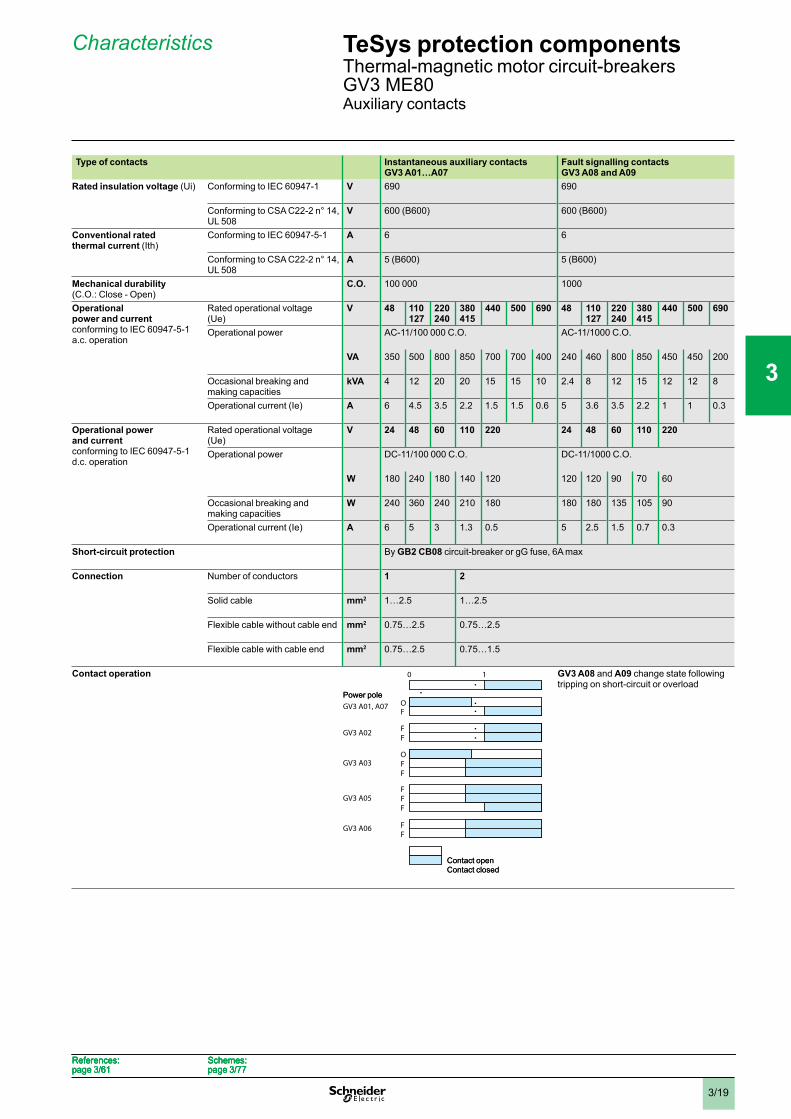
Type of contacts Instantaneous auxiliary contactsGV3 A01…A07
Fault signalling contacts GV3 A08 and A09
Rated insulation voltage (Ui) Conforming to IEC 60947-1 V 690 690
Conforming to CSA C22-2 n° 14,UL 508
V 600 (B600) 600 (B600)
Conventional rated thermal current (Ith)
Conforming to IEC 60947-5-1 A 6 6
Conforming to CSA C22-2 n° 14,UL 508
A 5 (B600) 5 (B600)
Mechanical durability(C.O.: Close - Open)
C.O. 100 000 1000
Operationalpower and currentconforming to IEC 60947-5-1a.c. operation
Rated operational voltage(Ue)
V 48 110 127
220240
380415
440 500 690 48 110 127
220240
380415
440 500 690
Operational power AC-11/100 000 C.O. AC-11/1000 C.O.
VA 350 500 800 850 700 700 400 240 460 800 850 450 450 200
Occasional breaking andmaking capacities
kVA 4 12 20 20 15 15 10 2.4 8 12 15 12 12 8
Operational current (Ie) A 6 4.5 3.5 2.2 1.5 1.5 0.6 5 3.6 3.5 2.2 1 1 0.3
Operational power and currentconforming to IEC 60947-5-1d.c. operation
Rated operational voltage(Ue)
V 24 48 60 110 220 24 48 60 110 220
Operational power DC-11/100 000 C.O. DC-11/1000 C.O.
W 180 240 180 140 120 120 120 90 70 60
Occasional breaking andmaking capacities
W 240 360 240 210 180 180 180 135 105 90
Operational current (Ie) A 6 5 3 1.3 0.5 5 2.5 1.5 0.7 0.3
Short-circuit protection By GB2 CB08 circuit-breaker or gG fuse, 6A max
Connection Number of conductors 1 2
Solid cable mm2 1…2.5 1…2.5
Flexible cable without cable end mm2 0.75…2.5 0.75…2.5
Flexible cable with cable end mm2 0.75…2.5 0.75…1.5
Contact operation GV3 A08 and A09 change state followingtripping on short-circuit or overload
Power pole
Contact openContact closed
Power pole
Contact openContact closed
References:page 3/61
Schemes:page 3/77
References:page 3/61
Schemes:page 3/77
References:page 3/61
Schemes:page 3/77
References:page 3/61
Schemes:page 3/77
TeSys protection componentsThermal-magnetic motor circuit-breakersGV3 ME80Auxiliary contacts
1
2
3
4
5
6
7
8
9
10
3/20
Characteristics
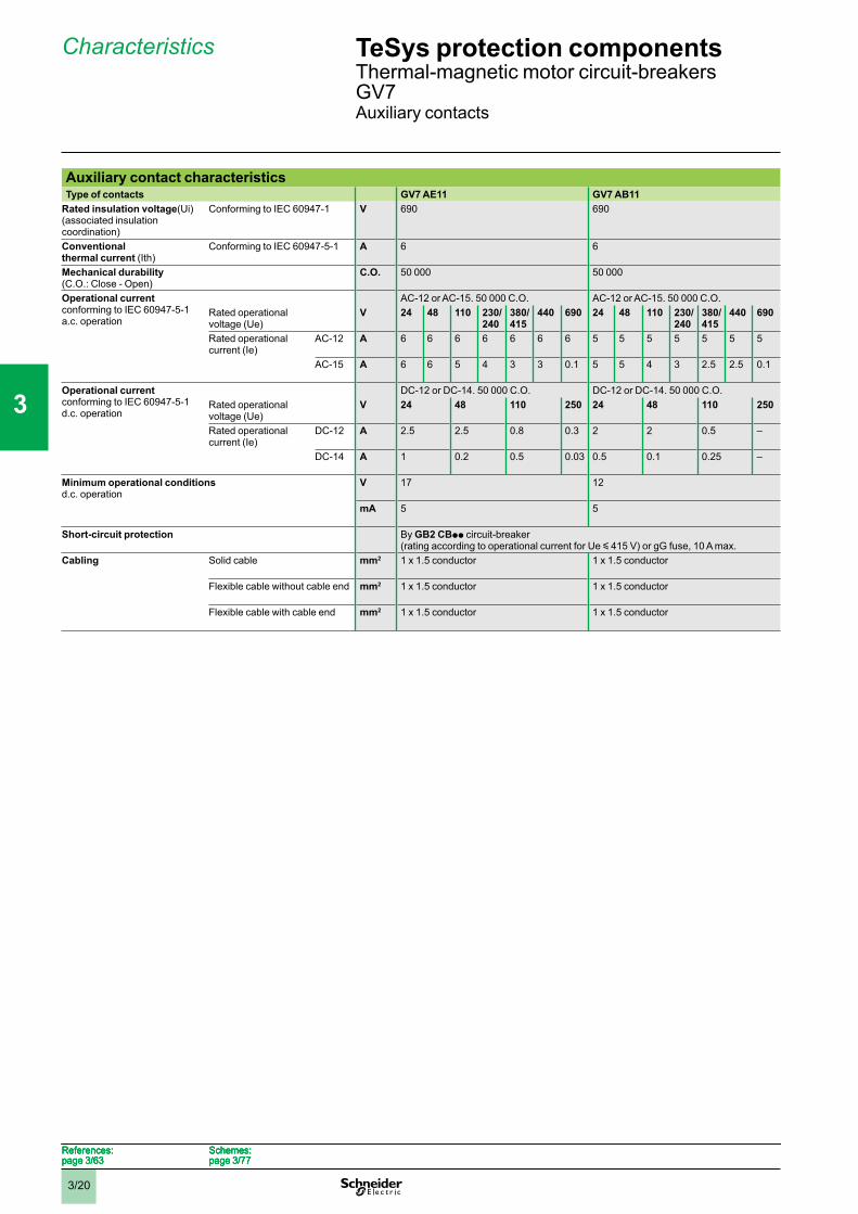
Auxiliary contact characteristicsType of contacts GV7 AE11 GV7 AB11
Rated insulation voltage(Ui)(associated insulationcoordination)
Conforming to IEC 60947-1 V 690 690
Conventionalthermal current (Ith)
Conforming to IEC 60947-5-1 A 6 6
Mechanical durability(C.O.: Close - Open)
C.O. 50 000 50 000
Operational currentconforming to IEC 60947-5-1a.c. operation
AC-12 or AC-15. 50 000 C.O. AC-12 or AC-15. 50 000 C.O.Rated operationalvoltage (Ue)
V 24 48 110 230/240
380/415
440 690 24 48 110 230/240
380/415
440 690
Rated operationalcurrent (Ie)
AC-12 A 6 6 6 6 6 6 6 5 5 5 5 5 5 5
AC-15 A 6 6 5 4 3 3 0.1 5 5 4 3 2.5 2.5 0.1
Operational currentconforming to IEC 60947-5-1d.c. operation
DC-12 or DC-14. 50 000 C.O. DC-12 or DC-14. 50 000 C.O.Rated operationalvoltage (Ue)
V 24 48 110 250 24 48 110 250
Rated operationalcurrent (Ie)
DC-12 A 2.5 2.5 0.8 0.3 2 2 0.5 –
DC-14 A 1 0.2 0.5 0.03 0.5 0.1 0.25 –
Minimum operational conditionsd.c. operation
V 17 12
mA 5 5
Short-circuit protection By GB2 CBpp circuit-breaker(rating according to operational current for Ue y 415 V) or gG fuse, 10 A max.
Cabling Solid cable mm2 1 x 1.5 conductor 1 x 1.5 conductor
Flexible cable without cable end mm2 1 x 1.5 conductor 1 x 1.5 conductor
Flexible cable with cable end mm2 1 x 1.5 conductor 1 x 1.5 conductor
References:page 3/63
Schemes:page 3/77
References:page 3/63
Schemes:page 3/77
References:page 3/63
Schemes:page 3/77
References:page 3/63
Schemes:page 3/77
TeSys protection componentsThermal-magnetic motor circuit-breakersGV7Auxiliary contacts
1
2
3
4
5
6
7
8
9
10
3/21
Characteristics
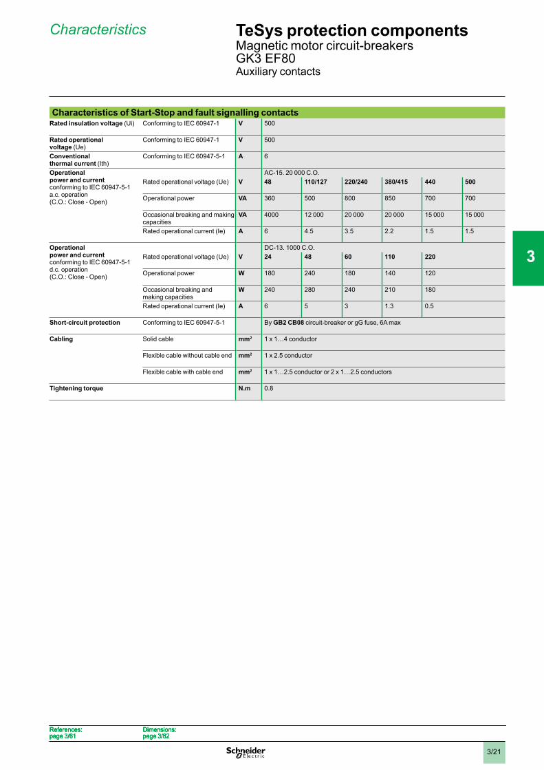
Characteristics of Start-Stop and fault signalling contactsRated insulation voltage (Ui) Conforming to IEC 60947-1 V 500
Rated operational voltage (Ue)
Conforming to IEC 60947-1 V 500
Conventionalthermal current (Ith)
Conforming to IEC 60947-5-1 A 6
Operationalpower and currentconforming to IEC 60947-5-1a.c. operation(C.O.: Close - Open)
AC-15. 20 000 C.O.Rated operational voltage (Ue) V 48 110/127 220/240 380/415 440 500
Operational power VA 360 500 800 850 700 700
Occasional breaking and makingcapacities
VA 4000 12 000 20 000 20 000 15 000 15 000
Rated operational current (Ie) A 6 4.5 3.5 2.2 1.5 1.5
Operationalpower and currentconforming to IEC 60947-5-1d.c. operation(C.O.: Close - Open)
DC-13. 1000 C.O.Rated operational voltage (Ue) V 24 48 60 110 220
Operational power W 180 240 180 140 120
Occasional breaking andmaking capacities
W 240 280 240 210 180
Rated operational current (Ie) A 6 5 3 1.3 0.5
Short-circuit protection Conforming to IEC 60947-5-1 By GB2 CB08 circuit-breaker or gG fuse, 6A max
Cabling Solid cable mm2 1 x 1…4 conductor
Flexible cable without cable end mm2 1 x 2.5 conductor
Flexible cable with cable end mm2 1 x 1…2.5 conductor or 2 x 1…2.5 conductors
Tightening torque N.m 0.8
References:page 3/61
Dimensions:page 3/82
References:page 3/61
Dimensions:page 3/82
References:page 3/61
Dimensions:page 3/82
References:page 3/61
Dimensions:page 3/82
TeSys protection componentsMagnetic motor circuit-breakersGK3 EF80Auxiliary contacts
1
2
3
4
5
6
7
8
9
10
3/22
Characteristics
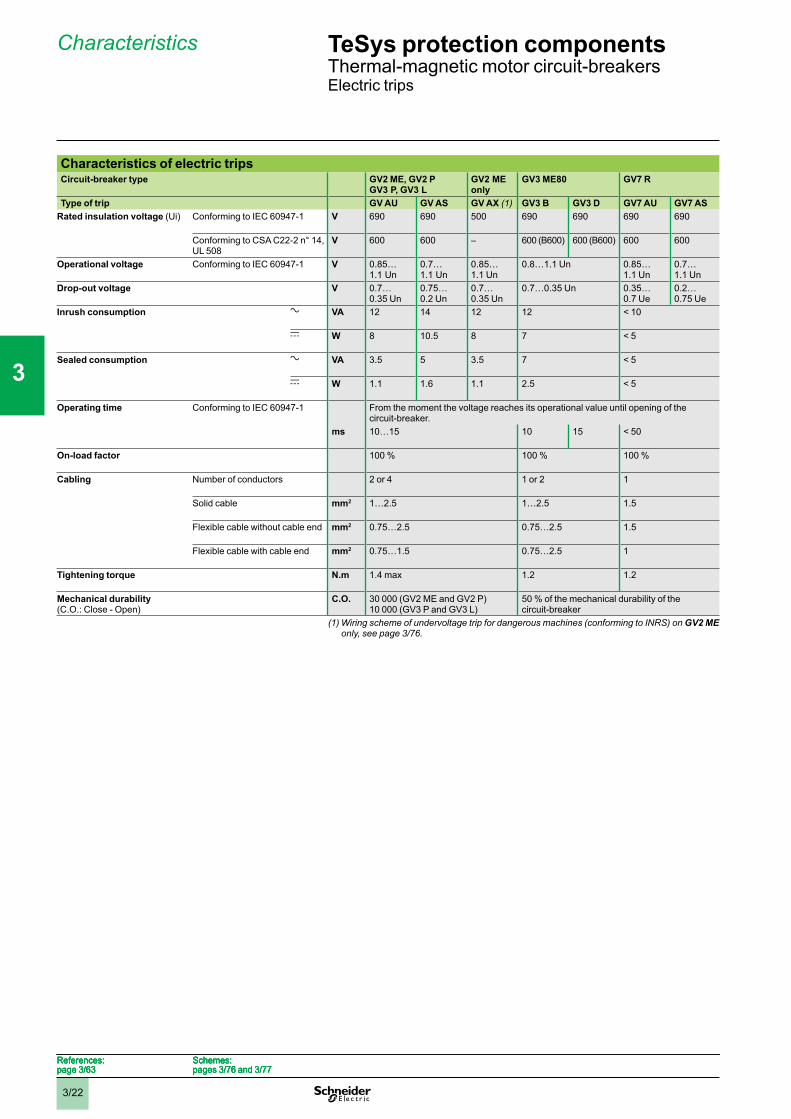
Characteristics of electric tripsCircuit-breaker type GV2 ME, GV2 P
GV3 P, GV3 LGV2 MEonly
GV3 ME80 GV7 R
Type of trip GV AU GV AS GV AX (1) GV3 B GV3 D GV7 AU GV7 ASRated insulation voltage (Ui) Conforming to IEC 60947-1 V 690 690 500 690 690 690 690
Conforming to CSA C22-2 n° 14,UL 508
V 600 600 – 600 (B600) 600 (B600) 600 600
Operational voltage Conforming to IEC 60947-1 V 0.85…1.1 Un
0.7…1.1 Un
0.85…1.1 Un
0.8…1.1 Un 0.85…1.1 Un
0.7…1.1 Un
Drop-out voltage V 0.7…0.35 Un
0.75…0.2 Un
0.7…0.35 Un
0.7…0.35 Un 0.35…0.7 Ue
0.2…0.75 Ue
Inrush consumption a VA 12 14 12 12 < 10
c W 8 10.5 8 7 < 5
Sealed consumption a VA 3.5 5 3.5 7 < 5
c W 1.1 1.6 1.1 2.5 < 5
Operating time Conforming to IEC 60947-1 From the moment the voltage reaches its operational value until opening of thecircuit-breaker.
ms 10…15 10 15 < 50
On-load factor 100 % 100 % 100 %
Cabling Number of conductors 2 or 4 1 or 2 1
Solid cable mm2 1…2.5 1…2.5 1.5
Flexible cable without cable end mm2 0.75…2.5 0.75…2.5 1.5
Flexible cable with cable end mm2 0.75…1.5 0.75…2.5 1
Tightening torque N.m 1.4 max 1.2 1.2
Mechanical durability(C.O.: Close - Open)
C.O. 30 000 (GV2 ME and GV2 P)10 000 (GV3 P and GV3 L)
50 % of the mechanical durability of thecircuit-breaker
(1) Wiring scheme of undervoltage trip for dangerous machines (conforming to INRS) on GV2 MEonly, see page 3/76.
References:page 3/63
Schemes:pages 3/76 and 3/77
References:page 3/63
Schemes:pages 3/76 and 3/77
References:page 3/63
Schemes:pages 3/76 and 3/77
References:page 3/63
Schemes:pages 3/76 and 3/77
TeSys protection componentsThermal-magnetic motor circuit-breakersElectric trips
1
2
3
4
5
6
7
8
9
10
3/23
Characteristics
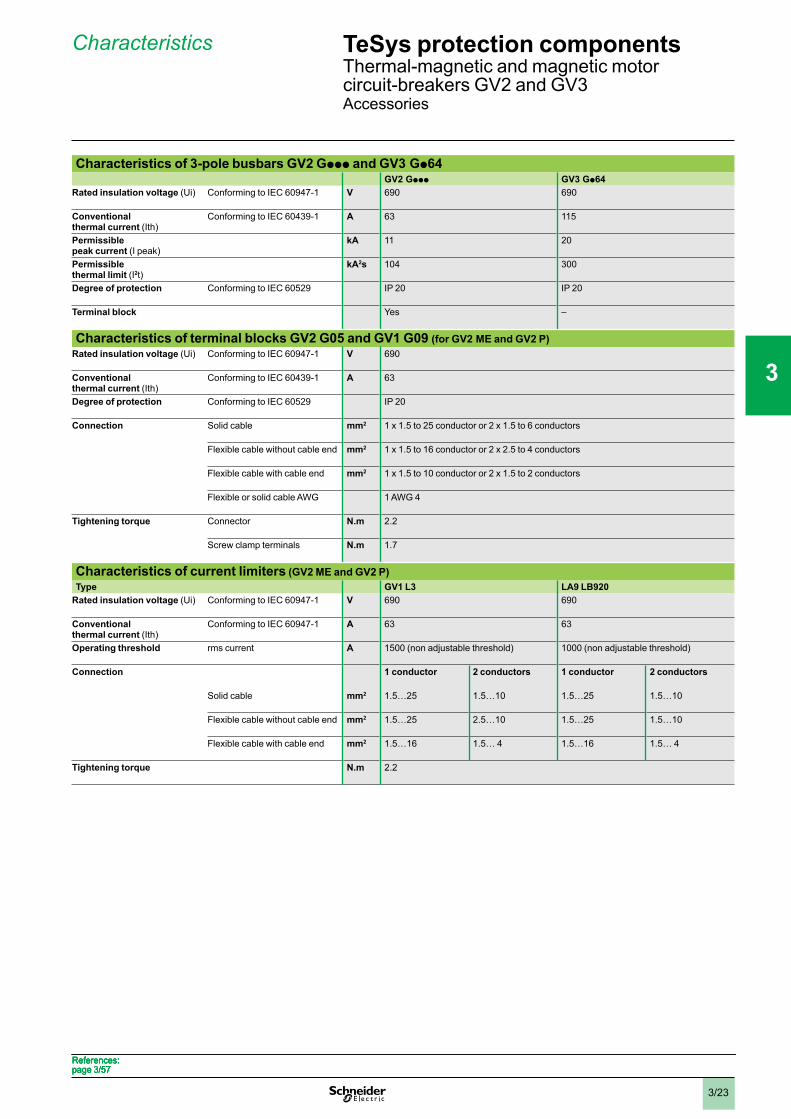
Characteristics of 3-pole busbars GV2 Gppp and GV3 Gp64GV2 Gppp GV3 Gp64
Rated insulation voltage (Ui) Conforming to IEC 60947-1 V 690 690
Conventionalthermal current (Ith)
Conforming to IEC 60439-1 A 63 115
Permissiblepeak current (I peak)
kA 11 20
Permissiblethermal limit (I2t)
kA2s 104 300
Degree of protection Conforming to IEC 60529 IP 20 IP 20
Terminal block Yes –
Characteristics of terminal blocks GV2 G05 and GV1 G09 (for GV2 ME and GV2 P)Rated insulation voltage (Ui) Conforming to IEC 60947-1 V 690
Conventionalthermal current (Ith)
Conforming to IEC 60439-1 A 63
Degree of protection Conforming to IEC 60529 IP 20
Connection Solid cable mm2 1 x 1.5 to 25 conductor or 2 x 1.5 to 6 conductors
Flexible cable without cable end mm2 1 x 1.5 to 16 conductor or 2 x 2.5 to 4 conductors
Flexible cable with cable end mm2 1 x 1.5 to 10 conductor or 2 x 1.5 to 2 conductors
Flexible or solid cable AWG 1 AWG 4
Tightening torque Connector N.m 2.2
Screw clamp terminals N.m 1.7
Characteristics of current limiters (GV2 ME and GV2 P)Type GV1 L3 LA9 LB920
Rated insulation voltage (Ui) Conforming to IEC 60947-1 V 690 690
Conventionalthermal current (Ith)
Conforming to IEC 60947-1 A 63 63
Operating threshold rms current A 1500 (non adjustable threshold) 1000 (non adjustable threshold)
Connection 1 conductor 2 conductors 1 conductor 2 conductors
Solid cable mm2 1.5…25 1.5…10 1.5…25 1.5…10
Flexible cable without cable end mm2 1.5…25 2.5…10 1.5…25 1.5…10
Flexible cable with cable end mm2 1.5…16 1.5… 4 1.5…16 1.5… 4
Tightening torque N.m 2.2
References:page 3/57References:page 3/57References:page 3/57References:page 3/57
TeSys protection componentsThermal-magnetic and magnetic motorcircuit-breakers GV2 and GV3Accessories
1
2
3
4
5
6
7
8
9
10
3/24
Curves
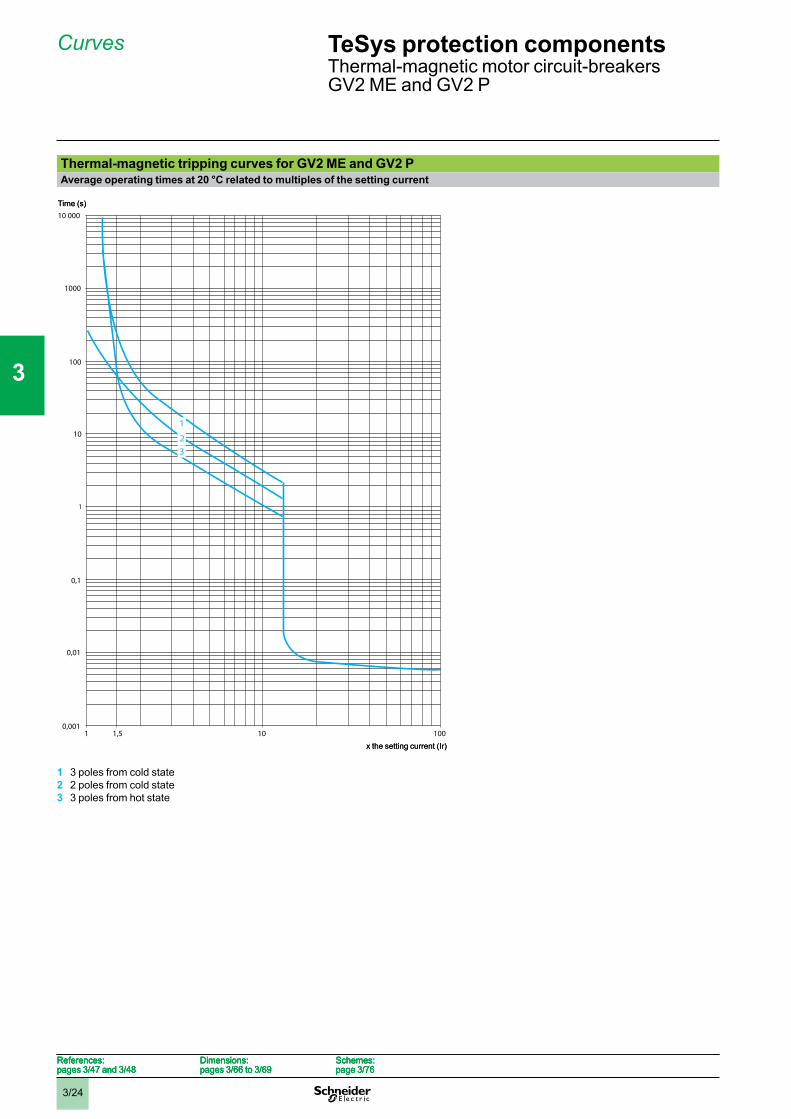
Thermal-magnetic tripping curves for GV2 ME and GV2 PAverage operating times at 20 °C related to multiples of the setting current
1 3 poles from cold state2 2 poles from cold state3 3 poles from hot state
0,001
0,1
1
10
100
0,01
1 1,5 10 100
1000
10 000
32
1
Time (s)
x the setting current (Ir)
0,001
0,1
1
10
100
0,01
1 1,5 10 100
1000
10 000
32
1
Time (s)
x the setting current (Ir)
References:pages 3/47 and 3/48
Dimensions:pages 3/66 to 3/69
Schemes:page 3/76
References:pages 3/47 and 3/48
Dimensions:pages 3/66 to 3/69
Schemes:page 3/76
References:pages 3/47 and 3/48
Dimensions:pages 3/66 to 3/69
Schemes:page 3/76
References:pages 3/47 and 3/48
Dimensions:pages 3/66 to 3/69
Schemes:page 3/76
TeSys protection componentsThermal-magnetic motor circuit-breakersGV2 ME and GV2 P
1
2
3
4
5
6
7
8
9
10
3/25
Curves (continued)
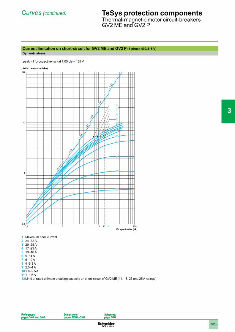
Current limitation on short-circuit for GV2 ME and GV2 P (3-phase 400/415 V)Dynamic stress
I peak = f (prospective Isc) at 1.05 Ue = 435 V
1 Maximum peak current2 24 -32 A3 20 -25 A4 17 -23 A5 13 -18 A6 9 -14 A7 6 -10 A8 4 -6.3 A9 2.5 -4 A101.6 -2.5 A11 1 -1.6 A12Limit of rated ultimate breaking capacity on short-circuit of GV2 ME (14, 18, 23 and 25 A ratings)
1
6
5
4
3
7
8
9
10
11
2
100
10
1
0,10,1 1 10 100
cos
= 0.
95
= 0.9
= 0.8
= 0.7
= 0.5
= 0.3
= 0.25
15 (12)
Limited peak current (kA)
Prospective Isc (kA)
1
6
5
4
3
7
8
9
10
11
2
100
10
1
0,10,1 1 10 100
cos
= 0.
95
= 0.9
= 0.8
= 0.7
= 0.5
= 0.3
= 0.25
15 (12)
Limited peak current (kA)
Prospective Isc (kA)
References:pages 3/47 and 3/48
Dimensions:pages 3/66 to 3/69
Schemes:page 3/76
References:pages 3/47 and 3/48
Dimensions:pages 3/66 to 3/69
Schemes:page 3/76
References:pages 3/47 and 3/48
Dimensions:pages 3/66 to 3/69
Schemes:page 3/76
References:pages 3/47 and 3/48
Dimensions:pages 3/66 to 3/69
Schemes:page 3/76
TeSys protection componentsThermal-magnetic motor circuit-breakersGV2 ME and GV2 P
1
2
3
4
5
6
7
8
9
10
3/26
Curves (continued)
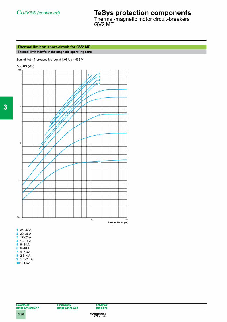
Thermal limit on short-circuit for GV2 METhermal limit in kA2s in the magnetic operating zone
Sum of I2dt = f (prospective Isc) at 1.05 Ue = 435 V
1 24 -32 A2 20 -25 A3 17 -23 A4 13 -18 A5 9 -14 A6 6 -10 A7 4 -6.3 A8 2.5 -4 A9 1.6 -2.5 A101 -1.6 A
100
10
1
0,1
0,010,1 1 10 100
345
6
7
8
9
10
21
Sum of I2dt (kA2s)
Prospective Isc (kA)
100
10
1
0,1
0,010,1 1 10 100
345
6
7
8
9
10
21
Sum of I2dt (kA2s)
Prospective Isc (kA)
References:pages 3/46 and 3/47
Dimensions:pages 3/66 to 3/69
Schemes:page 3/76
References:pages 3/46 and 3/47
Dimensions:pages 3/66 to 3/69
Schemes:page 3/76
References:pages 3/46 and 3/47
Dimensions:pages 3/66 to 3/69
Schemes:page 3/76
References:pages 3/46 and 3/47
Dimensions:pages 3/66 to 3/69
Schemes:page 3/76
TeSys protection componentsThermal-magnetic motor circuit-breakersGV2 ME
1
2
3
4
5
6
7
8
9
10
3/27
Curves (continued)
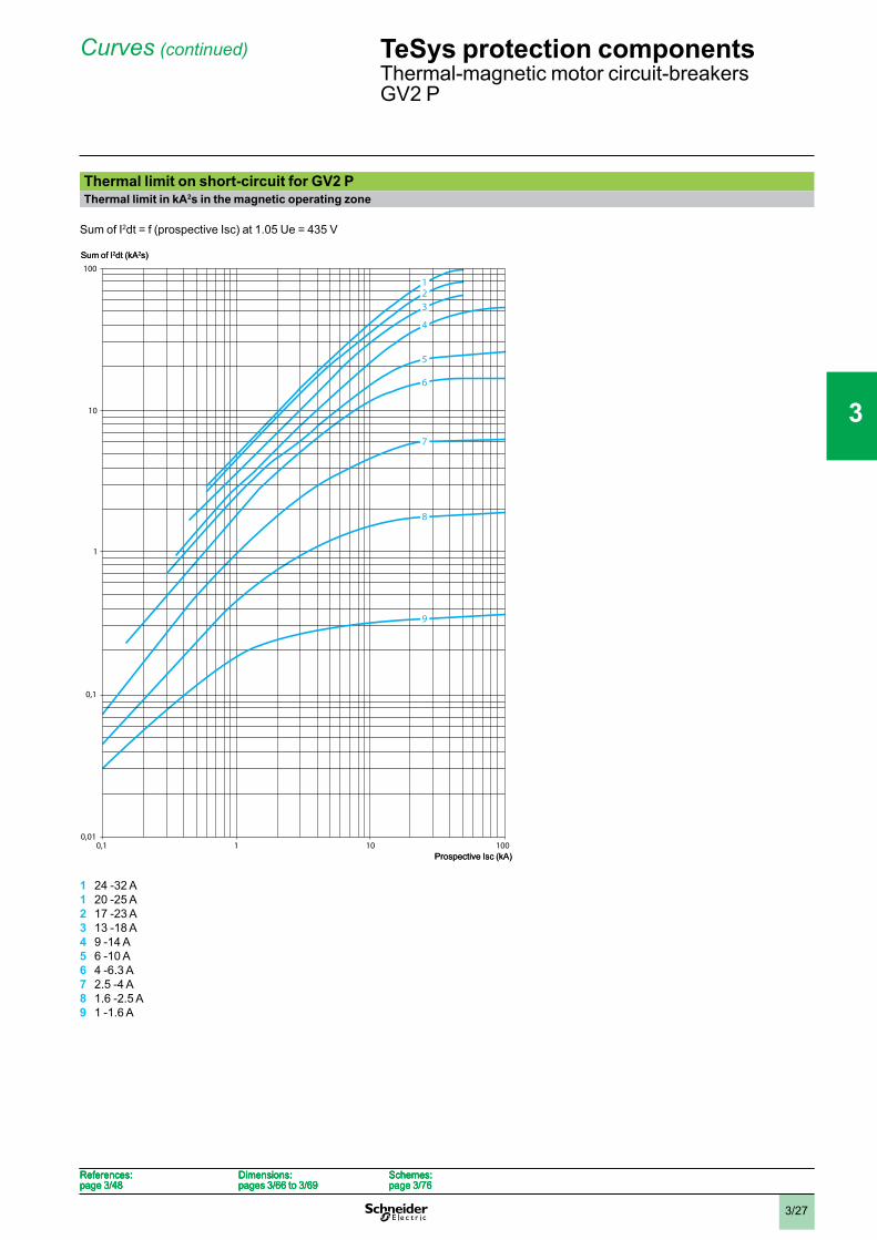
Thermal limit on short-circuit for GV2 PThermal limit in kA2s in the magnetic operating zone
Sum of I2dt = f (prospective Isc) at 1.05 Ue = 435 V
1 24 -32 A1 20 -25 A2 17 -23 A3 13 -18 A4 9 -14 A5 6 -10 A6 4 -6.3 A7 2.5 -4 A8 1.6 -2.5 A9 1 -1.6 A
100
10
1
0,1
0,010,1 1 10 100
123
4
5
6
7
8
9
Sum of I2dt (kA2s)
Prospective Isc (kA)
100
10
1
0,1
0,010,1 1 10 100
123
4
5
6
7
8
9
Sum of I2dt (kA2s)
Prospective Isc (kA)
References:page 3/48
Dimensions:pages 3/66 to 3/69
Schemes:page 3/76
References:page 3/48
Dimensions:pages 3/66 to 3/69
Schemes:page 3/76
References:page 3/48
Dimensions:pages 3/66 to 3/69
Schemes:page 3/76
References:page 3/48
Dimensions:pages 3/66 to 3/69
Schemes:page 3/76
TeSys protection componentsThermal-magnetic motor circuit-breakersGV2 P
1
2
3
4
5
6
7
8
9
10
3/28
Curves
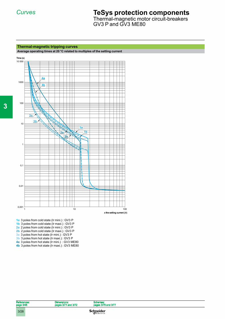
Thermal-magnetic tripping curvesAverage operating times at 20 °C related to multiples of the setting current
1a 3 poles from cold state (Ir mini.) : GV3 P1b 3 poles from cold state (Ir maxi.) : GV3 P2a 2 poles from cold state (Ir mini.) : GV3 P2b 2 poles from cold state (Ir maxi.) : GV3 P3a 3 poles from hot state (Ir mini.) : GV3 P3b 3 poles from hot state (Ir maxi.) : GV3 P4a 3 poles from hot state (Ir mini.) : GV3 ME804b 3 poles from hot state (Ir maxi.) : GV3 ME80
0,001
0,1
1
10
100
0,01
1 10 100
1000
10 000
1a1b2a
2b
3a
3b
4a
4b
Time (s)
x the setting current (Ir)
0,001
0,1
1
10
100
0,01
1 10 100
1000
10 000
1a1b2a
2b
3a
3b
4a
4b
Time (s)
x the setting current (Ir)
References:page 3/48
Dimensions:pages 3/71 and 3/72
Schemes:pages 3/76 and 3/77
References:page 3/48
Dimensions:pages 3/71 and 3/72
Schemes:pages 3/76 and 3/77
References:page 3/48
Dimensions:pages 3/71 and 3/72
Schemes:pages 3/76 and 3/77
References:page 3/48
Dimensions:pages 3/71 and 3/72
Schemes:pages 3/76 and 3/77
TeSys protection componentsThermal-magnetic motor circuit-breakersGV3 P and GV3 ME80
1
2
3
4
5
6
7
8
9
10
3/29
Curves (continued)
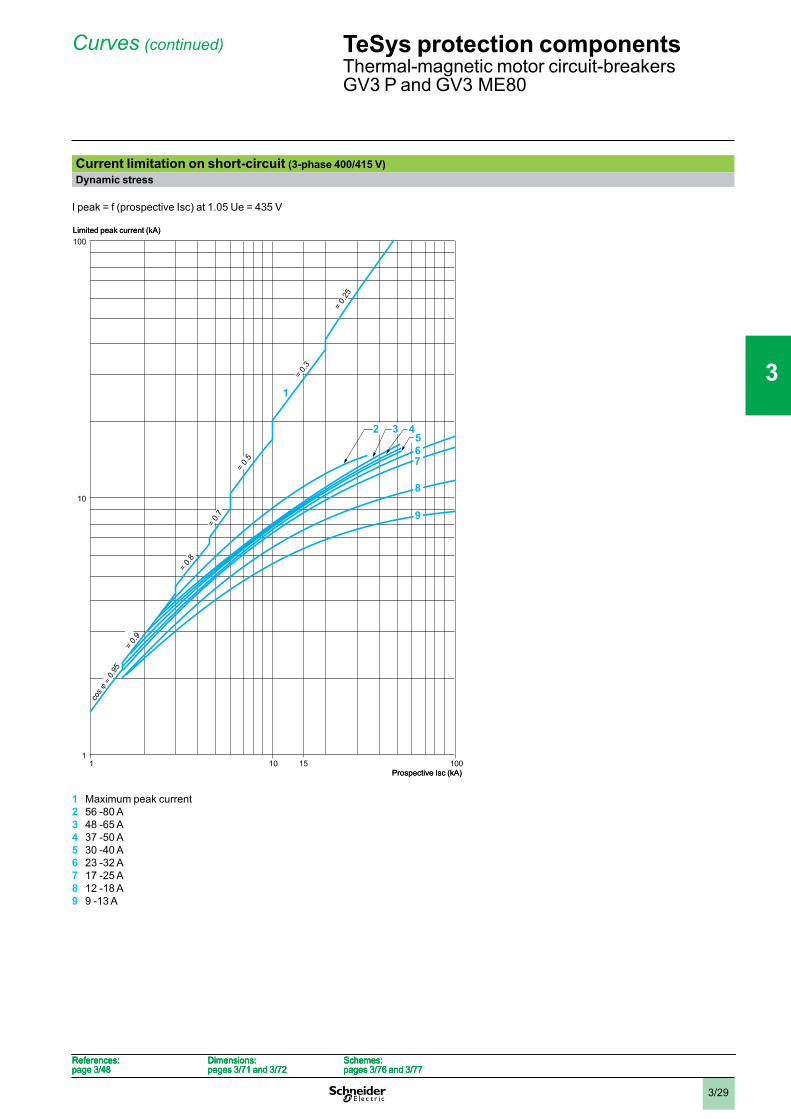
Current limitation on short-circuit (3-phase 400/415 V)Dynamic stress
I peak = f (prospective Isc) at 1.05 Ue = 435 V
1 Maximum peak current2 56 -80 A3 48 -65 A4 37 -50 A5 30 -40 A6 23 -32 A7 17 -25 A8 12 -18 A9 9 -13 A
1 10 15 100
100
10
1
76
8
9
= 0.9
= 0.8
= 0.
7
=0.5
= 0.3
= 0.
25
5
1
32 4
Limited peak current (kA)
Prospective Isc (kA)1 10 15 100
100
10
1
76
8
9
= 0.9
= 0.8
= 0.
7
=0.5
= 0.3
= 0.
25
5
1
32 4
Limited peak current (kA)
Prospective Isc (kA)
References:page 3/48
Dimensions:pages 3/71 and 3/72
Schemes:pages 3/76 and 3/77
References:page 3/48
Dimensions:pages 3/71 and 3/72
Schemes:pages 3/76 and 3/77
References:page 3/48
Dimensions:pages 3/71 and 3/72
Schemes:pages 3/76 and 3/77
References:page 3/48
Dimensions:pages 3/71 and 3/72
Schemes:pages 3/76 and 3/77
TeSys protection componentsThermal-magnetic motor circuit-breakersGV3 P and GV3 ME80
1
2
3
4
5
6
7
8
9
10
3/30
Curves (continued)
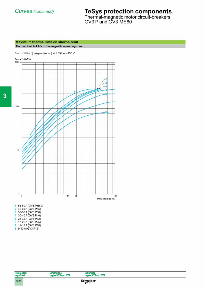
Maximum thermal limit on short-circuitThermal limit in kA2s in the magnetic operating zone
Sum of I2dt = f (prospective Isc) at 1.05 Ue = 435 V
1 56-80 A (GV3 ME80)2 48-65 A (GV3 P65)3 37-50 A (GV3 P50)4 30-40 A (GV3 P40)5 23-32 A (GV3 P32)6 17-25 A (GV3 P25)7 12-18 A (GV3 P18)8 9-13 A (GV3 P13)
100
1000
10
11 10 15 100
1
432
8
7
65
Sum of I2dt (kA2s)
Prospective Isc (kA)
100
1000
10
11 10 15 100
1
432
8
7
65
Sum of I2dt (kA2s)
Prospective Isc (kA)
References:page 3/48
Dimensions:pages 3/71 and 3/72
Schemes:pages 3/76 and 3/77
References:page 3/48
Dimensions:pages 3/71 and 3/72
Schemes:pages 3/76 and 3/77
References:page 3/48
Dimensions:pages 3/71 and 3/72
Schemes:pages 3/76 and 3/77
References:page 3/48
Dimensions:pages 3/71 and 3/72
Schemes:pages 3/76 and 3/77
TeSys protection componentsThermal-magnetic motor circuit-breakersGV3 P and GV3 ME80
1
2
3
4
5
6
7
8
9
10
3/31
Curves
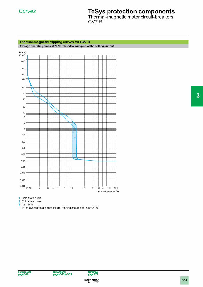
Thermal-magnetic tripping curves for GV7 RAverage operating times at 20 °C related to multiples of the setting current
1 Cold state curve2 Cold state curve3 12…14 Ir
In the event of total phase failure, tripping occurs after 4 s ± 20 %
0,001
0,002
0,1
0,01
0,005
0,05
1
0,5
0,02
0,2
2
5
10
20
50
100
200
500
1000
2000
5000
10 000
102 3 4 7 10020 30 405 50 701
3
1
1,12
2
Time (s)
x the setting current (Ir)
0,001
0,002
0,1
0,01
0,005
0,05
1
0,5
0,02
0,2
2
5
10
20
50
100
200
500
1000
2000
5000
10 000
102 3 4 7 10020 30 405 50 701
3
1
1,12
2
Time (s)
x the setting current (Ir)
References:page 3/49
Dimensions:pages 3/73 to 3/75
Schemes:page 3/77
References:page 3/49
Dimensions:pages 3/73 to 3/75
Schemes:page 3/77
References:page 3/49
Dimensions:pages 3/73 to 3/75
Schemes:page 3/77
References:page 3/49
Dimensions:pages 3/73 to 3/75
Schemes:page 3/77
TeSys protection componentsThermal-magnetic motor circuit-breakersGV7 R
1
2
3
4
5
6
7
8
9
10
3/32
Curves (continued)
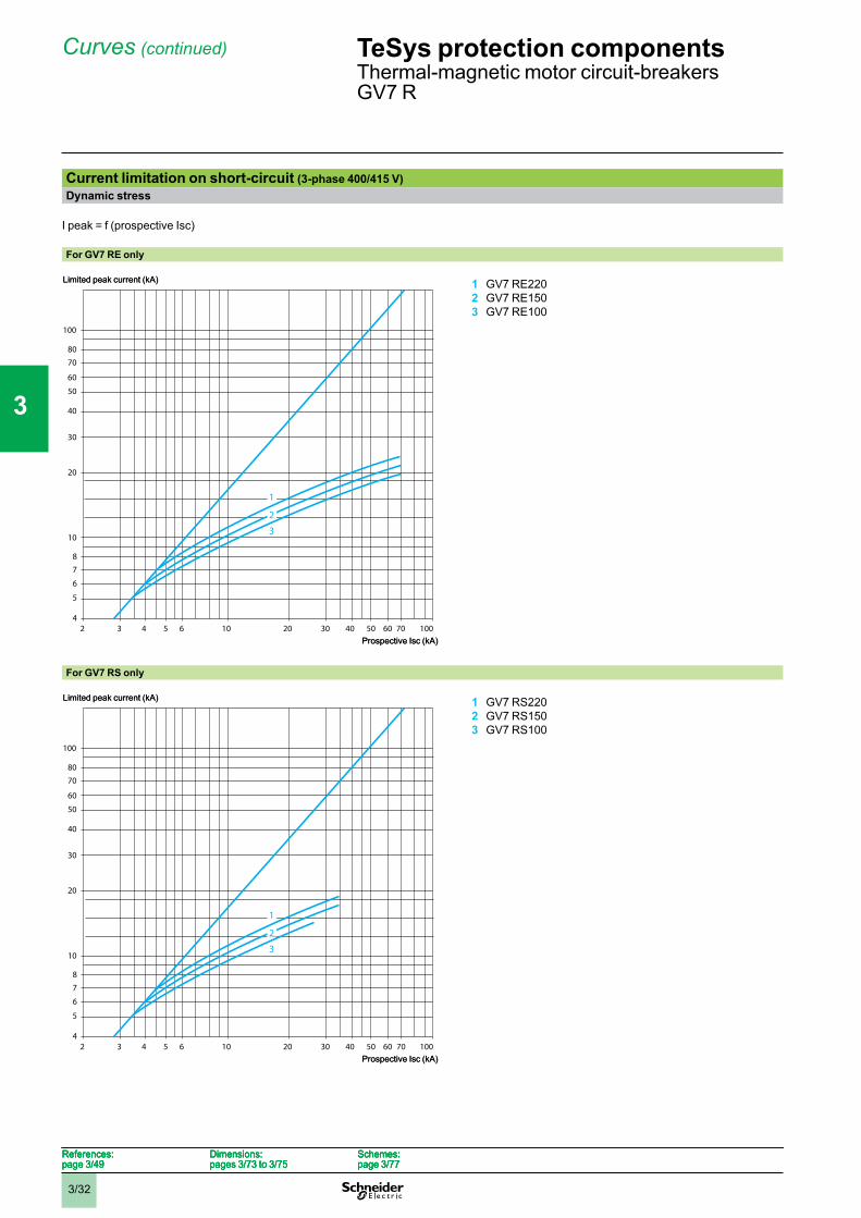
Current limitation on short-circuit (3-phase 400/415 V)Dynamic stress
I peak = f (prospective Isc)
For GV7 RE only
1 GV7 RE2202 GV7 RE1503 GV7 RE100
For GV7 RS only
1 GV7 RS2202 GV7 RS1503 GV7 RS100
4102
5
7
60
20
10
50
100
30
3 4 6 10020 30 40 60
40
70
5 50
6
8
80
1
2
3
70
Limited peak current (kA)
Prospective Isc (kA)
4102
5
7
60
20
10
50
100
30
3 4 6 10020 30 40 60
40
70
5 50
6
8
80
1
2
3
70
Limited peak current (kA)
Prospective Isc (kA)
4102
5
7
60
20
10
50
100
30
3 4 6 10020 30 40 60
40
70
5 50
1
2
3
6
8
80
70
Limited peak current (kA)
Prospective Isc (kA)
4102
5
7
60
20
10
50
100
30
3 4 6 10020 30 40 60
40
70
5 50
1
2
3
6
8
80
70
Limited peak current (kA)
Prospective Isc (kA)
References:page 3/49
Dimensions:pages 3/73 to 3/75
Schemes:page 3/77
References:page 3/49
Dimensions:pages 3/73 to 3/75
Schemes:page 3/77
References:page 3/49
Dimensions:pages 3/73 to 3/75
Schemes:page 3/77
References:page 3/49
Dimensions:pages 3/73 to 3/75
Schemes:page 3/77
TeSys protection componentsThermal-magnetic motor circuit-breakersGV7 R
1
2
3
4
5
6
7
8
9
10
3/33
Curves (continued)
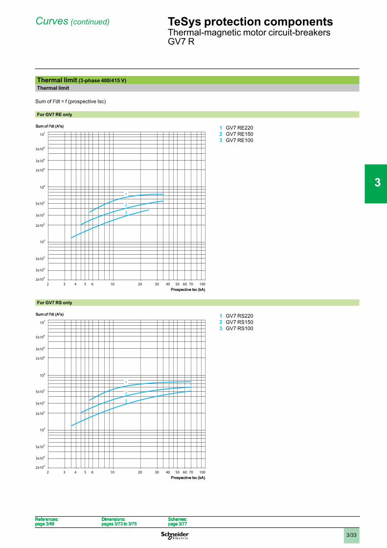
Thermal limit (3-phase 400/415 V)Thermal limit
Sum of I2dt = f (prospective Isc)
For GV7 RE only
1 GV7 RE2202 GV7 RE1503 GV7 RE100
For GV7 RS only
1 GV7 RS2202 GV7 RS1503 GV7 RS100
2x10⁴
102
3x10⁴
5x10⁴
2x10⁶
2x10⁵
105
106
107
5x10⁶
3x10⁵
3 4 6 10020 30 40 60
5x10⁵
3x10⁶
5 50 70
1
2
3
Sum of I2dt (A2s)
Prospective Isc (kA)
2x10⁴
102
3x10⁴
5x10⁴
2x10⁶
2x10⁵
105
106
107
5x10⁶
3x10⁵
3 4 6 10020 30 40 60
5x10⁵
3x10⁶
5 50 70
1
2
3
Sum of I2dt (A2s)
Prospective Isc (kA)
2x10⁴
102
3x10⁴
5x10⁴
2x10⁶
2x10⁵
105
106
107
5x10⁶
3x10⁵
3 4 6 10020 30 40 60
5x10⁵
3x10⁶
5 50 70
1
2
3
Sum of I2dt (A2s)
Prospective Isc (kA)
2x10⁴
102
3x10⁴
5x10⁴
2x10⁶
2x10⁵
105
106
107
5x10⁶
3x10⁵
3 4 6 10020 30 40 60
5x10⁵
3x10⁶
5 50 70
1
2
3
Sum of I2dt (A2s)
Prospective Isc (kA)
References:page 3/49
Dimensions:pages 3/73 to 3/75
Schemes:page 3/77
References:page 3/49
Dimensions:pages 3/73 to 3/75
Schemes:page 3/77
References:page 3/49
Dimensions:pages 3/73 to 3/75
Schemes:page 3/77
References:page 3/49
Dimensions:pages 3/73 to 3/75
Schemes:page 3/77
TeSys protection componentsThermal-magnetic motor circuit-breakersGV7 R
1
2
3
4
5
6
7
8
9
10

3/34
Curves (continued)
Current limitation on short-circuit (3-phase 690 V)Dynamic stress
I peak = f (prospective Isc)
For GV7 RE only
1 GV7 RE2202 GV7 RE150 and GV7 RE100
For GV7 RS only
1 GV7 RS2202 GV7 RS150 and GV7 RS100
4102
5
6
30
10
8
20
50
40
3 4 6 205
12
7
9
Limited peak current (kA)
Prospective Isc (kA)
4102
5
6
30
10
8
20
50
40
3 4 6 205
12
7
9
Limited peak current (kA)
Prospective Isc (kA)
4102
5
6
30
10
8
20
50
40
3 4 6 205
12
7
Limited peak current (kA)
Prospective Isc (kA)
4102
5
6
30
10
8
20
50
40
3 4 6 205
12
7
Limited peak current (kA)
Prospective Isc (kA)
References:page 3/49
Dimensions:pages 3/73 to 3/75
Schemes:page 3/77
References:page 3/49
Dimensions:pages 3/73 to 3/75
Schemes:page 3/77
References:page 3/49
Dimensions:pages 3/73 to 3/75
Schemes:page 3/77
References:page 3/49
Dimensions:pages 3/73 to 3/75
Schemes:page 3/77
TeSys protection componentsThermal-magnetic motor circuit-breakersGV7 R
1
2
3
4
5
6
7
8
9
10
3/35
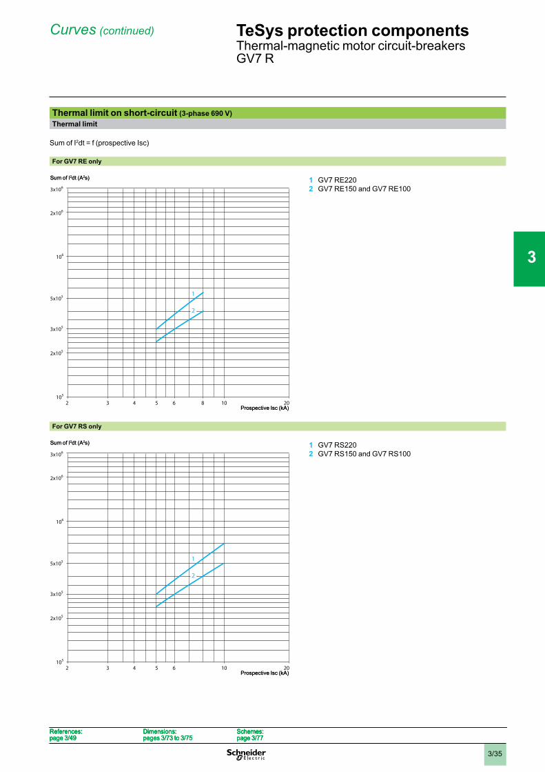
Curves (continued)
Thermal limit on short-circuit (3-phase 690 V)Thermal limit
Sum of I2dt = f (prospective Isc)
For GV7 RE only
1 GV7 RE2202 GV7 RE150 and GV7 RE100
For GV7 RS only
1 GV7 RS2202 GV7 RS150 and GV7 RS100
102 3 4 6 205
2x10⁶
2x10⁵
105
106
3x10⁵
5x10⁵
3x10⁶
1
2
8
Sum of I2dt (A2s)
Prospective Isc (kA)102 3 4 6 205
2x10⁶
2x10⁵
105
106
3x10⁵
5x10⁵
3x10⁶
1
2
8
Sum of I2dt (A2s)
Prospective Isc (kA)
102 3 4 6 205
2x10⁶
2x10⁵
105
106
3x10⁵
5x10⁵
3x10⁶
1
2
Sum of I2dt (A2s)
Prospective Isc (kA)102 3 4 6 205
2x10⁶
2x10⁵
105
106
3x10⁵
5x10⁵
3x10⁶
1
2
Sum of I2dt (A2s)
Prospective Isc (kA)
References:page 3/49
Dimensions:pages 3/73 to 3/75
Schemes:page 3/77
References:page 3/49
Dimensions:pages 3/73 to 3/75
Schemes:page 3/77
References:page 3/49
Dimensions:pages 3/73 to 3/75
Schemes:page 3/77
References:page 3/49
Dimensions:pages 3/73 to 3/75
Schemes:page 3/77
TeSys protection componentsThermal-magnetic motor circuit-breakersGV7 R
1
2
3
4
5
6
7
8
9
10
3/36
Curves
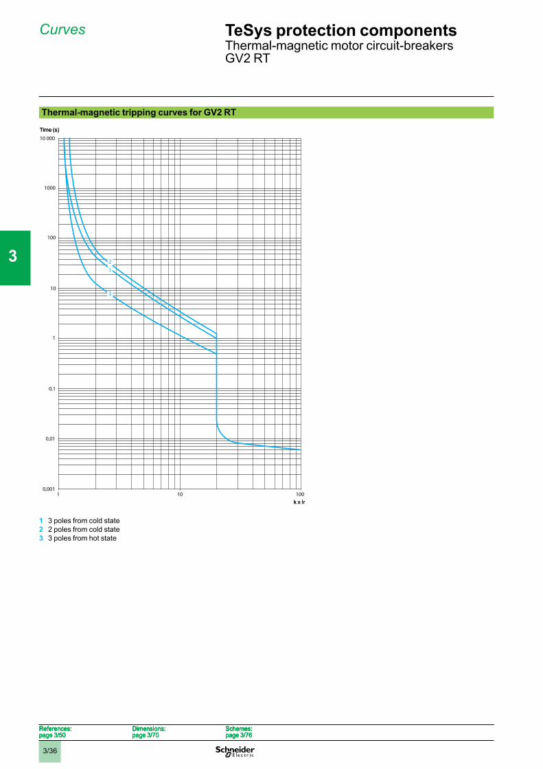
Thermal-magnetic tripping curves for GV2 RT
1 3 poles from cold state2 2 poles from cold state3 3 poles from hot state
10
10 000
1
0,1
0,0011 10 100
1000
100
0,01
21
3
Time (s)
k x Ir
10
10 000
1
0,1
0,0011 10 100
1000
100
0,01
21
3
Time (s)
k x Ir
References:page 3/50
Dimensions:page 3/70
Schemes:page 3/76
References:page 3/50
Dimensions:page 3/70
Schemes:page 3/76
References:page 3/50
Dimensions:page 3/70
Schemes:page 3/76
References:page 3/50
Dimensions:page 3/70
Schemes:page 3/76
TeSys protection componentsThermal-magnetic motor circuit-breakersGV2 RT
1
2
3
4
5
6
7
8
9
10
3/37
Curves
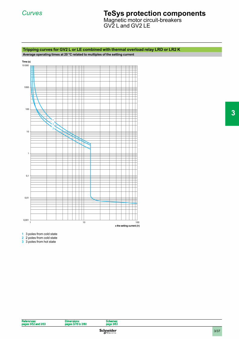
Tripping curves for GV2 L or LE combined with thermal overload relay LRD or LR2 KAverage operating times at 20 °C related to multiples of the setting current
1 3 poles from cold state2 2 poles from cold state3 3 poles from hot state
10
10 000
1
0,1
0,0011 10 100
1000
100
0,01
32
1
Time (s)
x the setting current (Ir)
10
10 000
1
0,1
0,0011 10 100
1000
100
0,01
32
1
Time (s)
x the setting current (Ir)
References:pages 3/52 and 3/53
Dimensions:pages 3/78 to 3/80
Schemes:page 3/83
References:pages 3/52 and 3/53
Dimensions:pages 3/78 to 3/80
Schemes:page 3/83
References:pages 3/52 and 3/53
Dimensions:pages 3/78 to 3/80
Schemes:page 3/83
References:pages 3/52 and 3/53
Dimensions:pages 3/78 to 3/80
Schemes:page 3/83
TeSys protection componentsMagnetic motor circuit-breakersGV2 L and GV2 LE
1
2
3
4
5
6
7
8
9
10
3/38
Curves (continued)
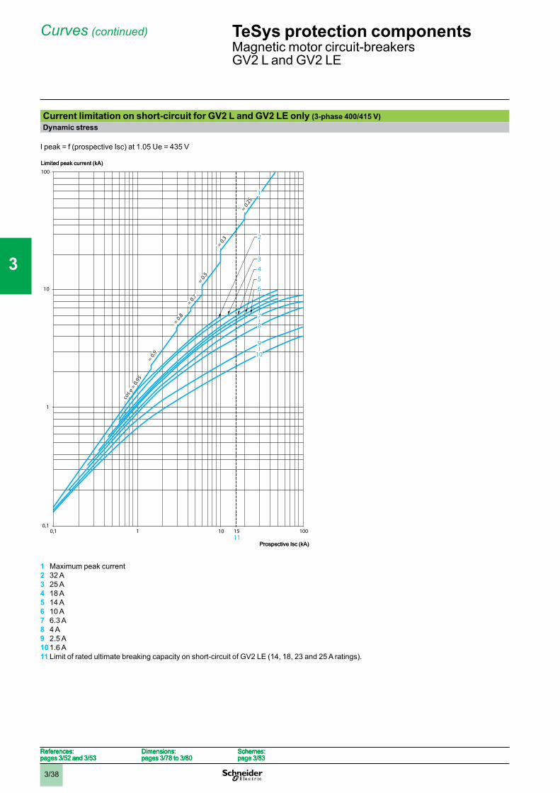
Current limitation on short-circuit for GV2 L and GV2 LE only (3-phase 400/415 V)Dynamic stress
I peak = f (prospective Isc) at 1.05 Ue = 435 V
1 Maximum peak current2 32 A3 25 A4 18 A5 14 A6 10 A7 6.3 A8 4 A9 2.5 A101.6 A11 Limit of rated ultimate breaking capacity on short-circuit of GV2 LE (14, 18, 23 and 25 A ratings).
100
10
1
0,10,1 1 100
1
543
8
9
10
7
6
cos
= 0.
95
= 0.9
= 0.8
= 0.7
= 0.5
= 0.3
= 0.25
151011
2
Limited peak current (kA)
Prospective Isc (kA)
100
10
1
0,10,1 1 100
1
543
8
9
10
7
6
cos
= 0.
95
= 0.9
= 0.8
= 0.7
= 0.5
= 0.3
= 0.25
151011
2
Limited peak current (kA)
Prospective Isc (kA)
References:pages 3/52 and 3/53
Dimensions:pages 3/78 to 3/80
Schemes:page 3/83
References:pages 3/52 and 3/53
Dimensions:pages 3/78 to 3/80
Schemes:page 3/83
References:pages 3/52 and 3/53
Dimensions:pages 3/78 to 3/80
Schemes:page 3/83
References:pages 3/52 and 3/53
Dimensions:pages 3/78 to 3/80
Schemes:page 3/83
TeSys protection componentsMagnetic motor circuit-breakersGV2 L and GV2 LE
1
2
3
4
5
6
7
8
9
10
3/39
Curves (continued)
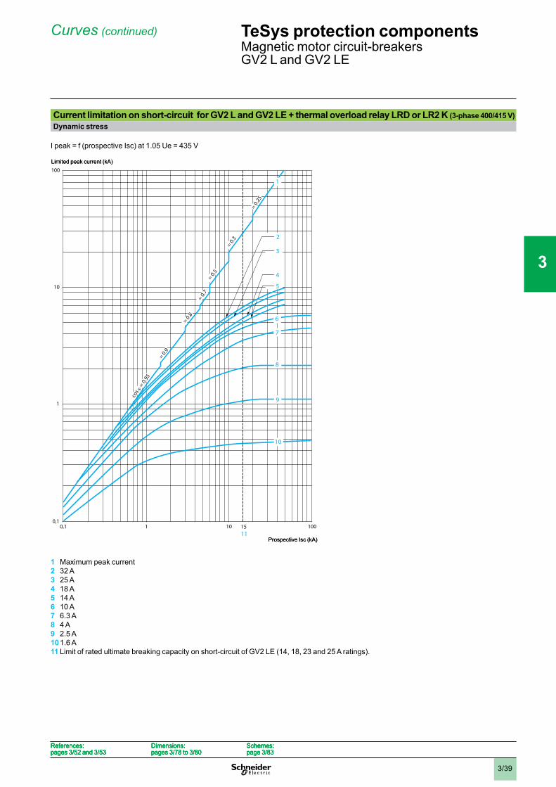
Current limitation on short-circuit for GV2 L and GV2 LE + thermal overload relay LRD or LR2 K (3-phase 400/415 V)Dynamic stress
I peak = f (prospective Isc) at 1.05 Ue = 435 V
1 Maximum peak current2 32 A3 25 A4 18 A5 14 A6 10 A7 6.3 A8 4 A9 2.5 A101.6 A11 Limit of rated ultimate breaking capacity on short-circuit of GV2 LE (14, 18, 23 and 25 A ratings).
100
10
1
0,10,1 1 10 100
cos
= 0.
95
= 0.9
= 0.8
= 0.7
= 0.5
= 0.3
= 0.25
1511
1
2
3
4
5
6
7
8
9
10
Limited peak current (kA)
Prospective Isc (kA)
100
10
1
0,10,1 1 10 100
cos
= 0.
95
= 0.9
= 0.8
= 0.7
= 0.5
= 0.3
= 0.25
1511
1
2
3
4
5
6
7
8
9
10
Limited peak current (kA)
Prospective Isc (kA)
References:pages 3/52 and 3/53
Dimensions:pages 3/78 to 3/80
Schemes:page 3/83
References:pages 3/52 and 3/53
Dimensions:pages 3/78 to 3/80
Schemes:page 3/83
References:pages 3/52 and 3/53
Dimensions:pages 3/78 to 3/80
Schemes:page 3/83
References:pages 3/52 and 3/53
Dimensions:pages 3/78 to 3/80
Schemes:page 3/83
TeSys protection componentsMagnetic motor circuit-breakersGV2 L and GV2 LE
1
2
3
4
5
6
7
8
9
10
3/40
Curves (continued)
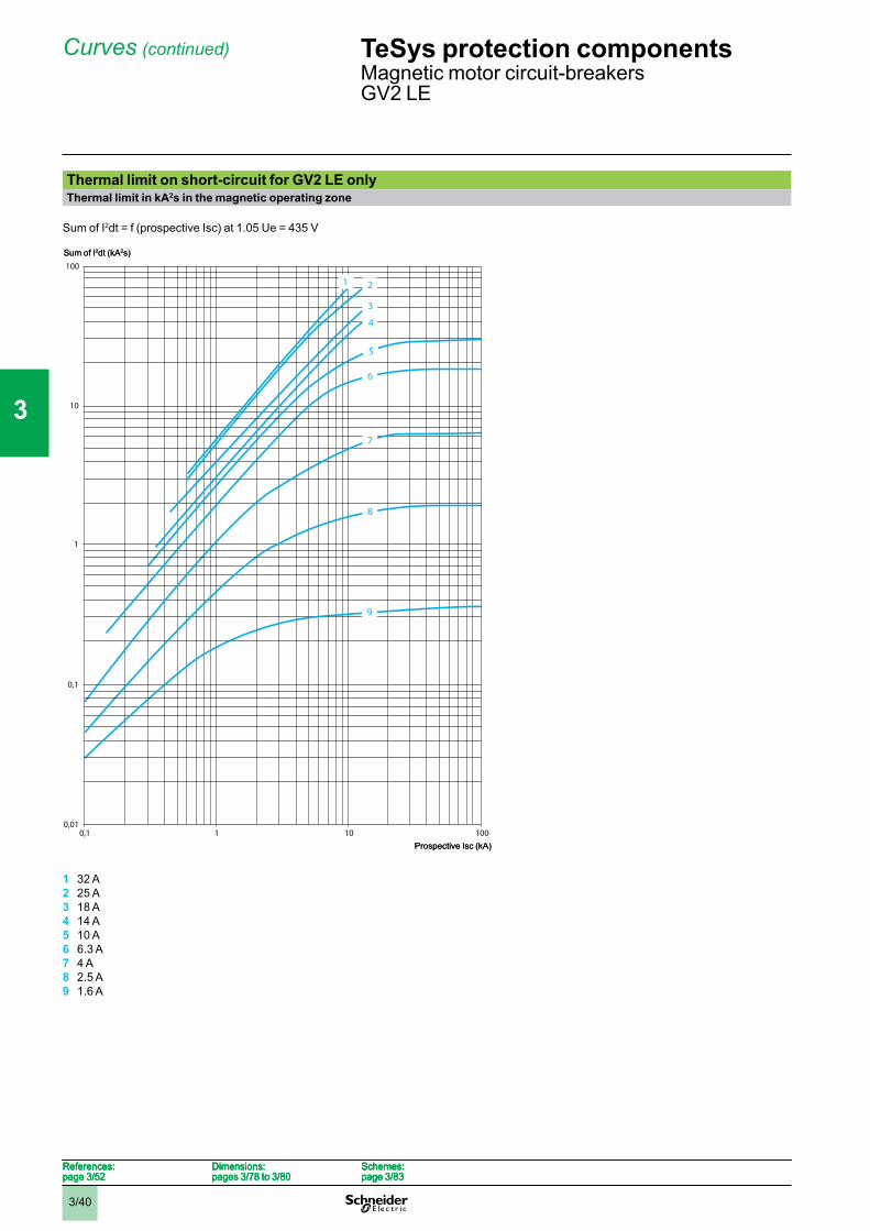
Thermal limit on short-circuit for GV2 LE onlyThermal limit in kA2s in the magnetic operating zone
Sum of I2dt = f (prospective Isc) at 1.05 Ue = 435 V
1 32 A2 25 A3 18 A4 14 A5 10 A6 6.3 A7 4 A8 2.5 A9 1.6 A
100
10
1
0,1
0,010,1 1 10 100
1 2
3
4
5
6
7
8
9
Sum of I2dt (kA2s)
Prospective Isc (kA)
100
10
1
0,1
0,010,1 1 10 100
1 2
3
4
5
6
7
8
9
Sum of I2dt (kA2s)
Prospective Isc (kA)
References:page 3/52
Dimensions:pages 3/78 to 3/80
Schemes:page 3/83
References:page 3/52
Dimensions:pages 3/78 to 3/80
Schemes:page 3/83
References:page 3/52
Dimensions:pages 3/78 to 3/80
Schemes:page 3/83
References:page 3/52
Dimensions:pages 3/78 to 3/80
Schemes:page 3/83
TeSys protection componentsMagnetic motor circuit-breakersGV2 LE
1
2
3
4
5
6
7
8
9
10

3/41
Curves (continued)
Thermal limit on short-circuit for GV2 L onlyThermal limit in kA2s in the magnetic operating zone
Sum of I2dt = f (prospective Isc) at 1.05 Ue = 435 V
1 25 A and 32 A2 18 A3 14 A4 10 A5 6.3 A6 4 A7 2.5 A8 1.6 A
100
10
1
0,1
0,010,1 1 10 100
1234
5
6
8
7
Sum of I2dt (kA2s)
Prospective Isc (kA)
100
10
1
0,1
0,010,1 1 10 100
1234
5
6
8
7
Sum of I2dt (kA2s)
Prospective Isc (kA)
References:page 3/53
Dimensions:pages 3/78 to 3/80
Schemes:page 3/83
References:page 3/53
Dimensions:pages 3/78 to 3/80
Schemes:page 3/83
References:page 3/53
Dimensions:pages 3/78 to 3/80
Schemes:page 3/83
References:page 3/53
Dimensions:pages 3/78 to 3/80
Schemes:page 3/83
TeSys protection componentsMagnetic motor circuit-breakersGV2 L
1
2
3
4
5
6
7
8
9
10
3/42
Curves (continued)
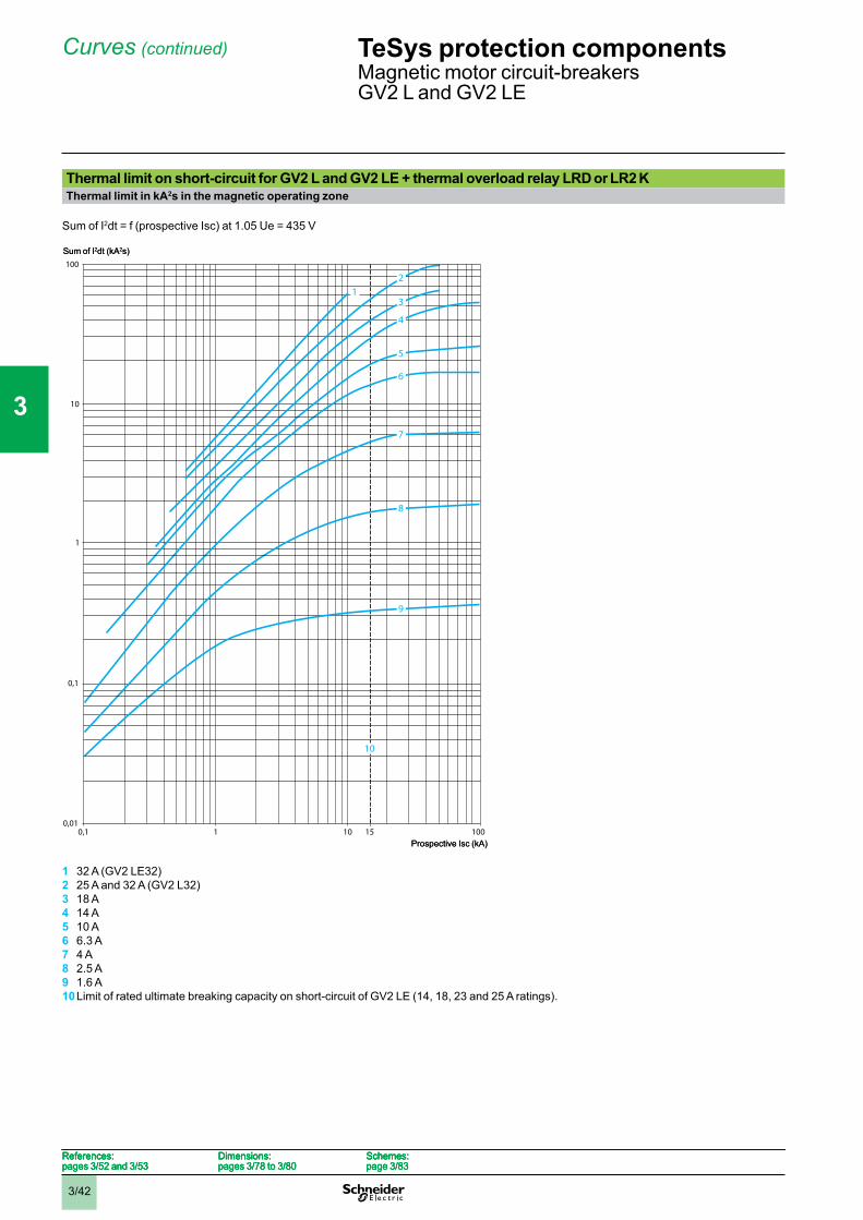
Thermal limit on short-circuit for GV2 L and GV2 LE + thermal overload relay LRD or LR2 KThermal limit in kA2s in the magnetic operating zone
Sum of I2dt = f (prospective Isc) at 1.05 Ue = 435 V
1 32 A (GV2 LE32)2 25 A and 32 A (GV2 L32)3 18 A4 14 A5 10 A6 6.3 A7 4 A8 2.5 A9 1.6 A10Limit of rated ultimate breaking capacity on short-circuit of GV2 LE (14, 18, 23 and 25 A ratings).
100
10
1
0,1
0,010,1 1 10 100
2
3
4
5
6
7
8
9
15
1
10
Sum of I2dt (kA2s)
Prospective Isc (kA)
100
10
1
0,1
0,010,1 1 10 100
2
3
4
5
6
7
8
9
15
1
10
Sum of I2dt (kA2s)
Prospective Isc (kA)
References:pages 3/52 and 3/53
Dimensions:pages 3/78 to 3/80
Schemes:page 3/83
References:pages 3/52 and 3/53
Dimensions:pages 3/78 to 3/80
Schemes:page 3/83
References:pages 3/52 and 3/53
Dimensions:pages 3/78 to 3/80
Schemes:page 3/83
References:pages 3/52 and 3/53
Dimensions:pages 3/78 to 3/80
Schemes:page 3/83
TeSys protection componentsMagnetic motor circuit-breakersGV2 L and GV2 LE
1
2
3
4
5
6
7
8
9
10
3/43
Curves
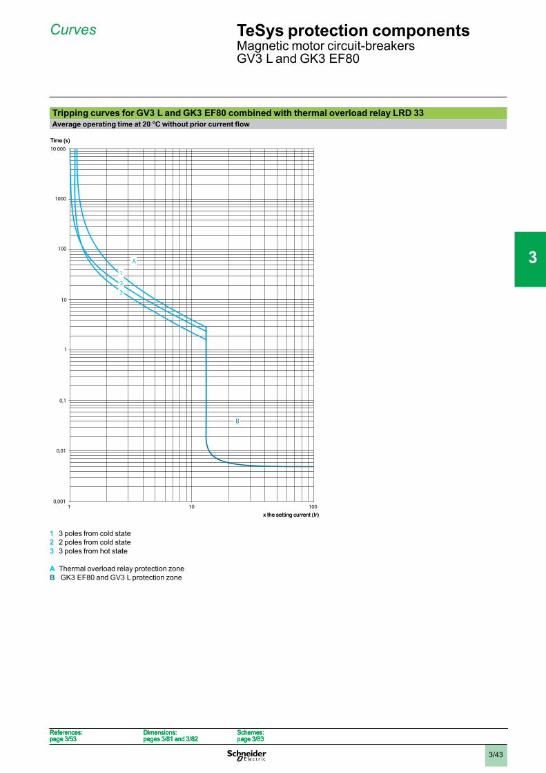
Tripping curves for GV3 L and GK3 EF80 combined with thermal overload relay LRD 33
1 3 poles from cold state2 2 poles from cold state3 3 poles from hot state
A Thermal overload relay protection zoneB GK3 EF80 and GV3 L protection zone
10
10 000
1
0,1
0,0011 10 100
1000
100
0,01
32
1
B
A
Time (s)
x the setting current (Ir)
10
10 000
1
0,1
0,0011 10 100
1000
100
0,01
32
1
B
A
Time (s)
x the setting current (Ir)
References:page 3/53
Dimensions:pages 3/81 and 3/82
Schemes:page 3/83
References:page 3/53
Dimensions:pages 3/81 and 3/82
Schemes:page 3/83
References:page 3/53
Dimensions:pages 3/81 and 3/82
Schemes:page 3/83
References:page 3/53
Dimensions:pages 3/81 and 3/82
Schemes:page 3/83
TeSys protection componentsMagnetic motor circuit-breakersGV3 L and GK3 EF80
1
2
3
4
5
6
7
8
9
10
3/44
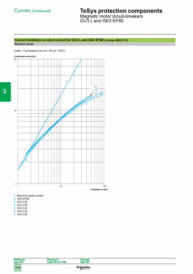
Curves (continued)
Current limitation on short-circuit for GV3 L and GK3 EF80 (3-phase 400/415 V)Dynamic stress
I peak = f (prospective Isc) at 1.05 Ue = 435 V
1 Maximum peak current2 GK3 EF803 GV3 L654 GV3 L505 GV3 L406 GV3 L327 GV3 L25
11 10 100
10
50
2
1
543
76
Limited peak current (kA)
Prospective Isc (kA)
11 10 100
10
50
2
1
543
76
Limited peak current (kA)
Prospective Isc (kA)
References:page 3/53
Dimensions:pages 3/81 and 3/82
Schemes:page 3/83
References:page 3/53
Dimensions:pages 3/81 and 3/82
Schemes:page 3/83
References:page 3/53
Dimensions:pages 3/81 and 3/82
Schemes:page 3/83
References:page 3/53
Dimensions:pages 3/81 and 3/82
Schemes:page 3/83
TeSys protection componentsMagnetic motor circuit-breakersGV3 L and GK3 EF80
1
2
3
4
5
6
7
8
9
10
3/45
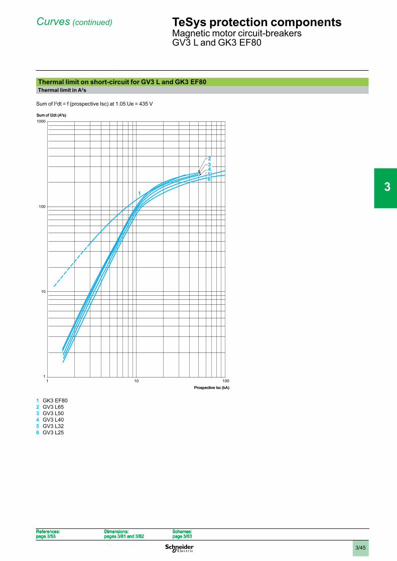
Curves (continued)
Thermal limit on short-circuit for GV3 L and GK3 EF80Thermal limit in A2s
Sum of I2dt = f (prospective Isc) at 1.05 Ue = 435 V
1 GK3 EF802 GV3 L653 GV3 L504 GV3 L405 GV3 L326 GV3 L25
10
11 10 100
100
1000
1
432
56
Sum of I2dt (A2s)
Prospective Isc (kA)
10
11 10 100
100
1000
1
432
56
Sum of I2dt (A2s)
Prospective Isc (kA)
References:page 3/53
Dimensions:pages 3/81 and 3/82
Schemes:page 3/83
References:page 3/53
Dimensions:pages 3/81 and 3/82
Schemes:page 3/83
References:page 3/53
Dimensions:pages 3/81 and 3/82
Schemes:page 3/83
References:page 3/53
Dimensions:pages 3/81 and 3/82
Schemes:page 3/83
TeSys protection componentsMagnetic motor circuit-breakersGV3 L and GK3 EF80
1
2
3
4
5
6
7
8
9
10
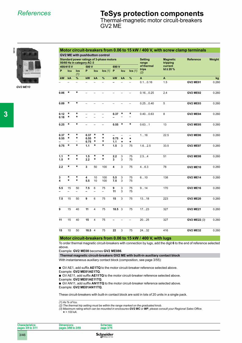
3/46
TeSys protection componentsThermal-magnetic motor circuit-breakersGV2 ME
References
Motor circuit-breakers from 0.06 to 15 kW / 400 V, with screw clamp terminalsGV2 ME with pushbutton controlStandard power ratings of 3-phase motors 50/60 Hz in category AC-3
Settingrangeof thermal trips(2)
MagnetictrippingcurrentId ± 20 %
Reference Weight
400/415 V 500 V 690 VP Icu Ics
(1)P Icu Ics (1) P Icu Ics (1)
kW kA % kW kA % kW kA % A A kg– – – – – – – – – 0.1…0.16 1.5 GV2 ME01 0.260
0.06 g g – – – – – – 0.16…0.25 2.4 GV2 ME02 0.260
0.09 g g – – – – – – 0.25…0.40 5 GV2 ME03 0.260
0.120.18
gg
gg
––
––
––
0.37–
g–
g–
0.40…0.63 8 GV2 ME04 0.260
0.25 g g – – – 0.55 g g 0.63…1 13 GV2 ME05 0.260
0.370.55–
gg–
gg–
0.370.550.75
ggg
ggg
–0.751.1
–gg
–gg
1…16 22.5 GV2 ME06 0.260
0.75 g g 1.1 g g 1.5 3 75 1.6…2.5 33.5 GV2 ME07 0.260
1.11.5
gg
gg
1.52.2
gg
gg
2.23
33
7575
2.5…4 51 GV2 ME08 0.260
2.2 g g 3 50 100 4 3 75 4…6.3 78 GV2 ME10 0.260
34
gg
gg
45.5
1010
100100
5.57.5
33
7575
6…10 138 GV2 ME14 0.260
5.5–
15–
50–
7.5–
6–
75–
911
33
7575
9…14 170 GV2 ME16 0.260
7.5 15 50 9 6 75 15 3 75 13…18 223 GV2 ME20 0.260
9 15 40 11 4 75 18.5 3 75 17…23 327 GV2 ME21 0.260
11 15 40 15 4 75 – – – 20…25 327 GV2 ME22 (3) 0.260
15 10 50 18.5 4 75 22 3 75 24…32 416 GV2 ME32 0.260
Motor circuit-breakers from 0.06 to 15 kW / 400 V, with lugsTo order thermal magnetic circuit-breakers with connection by lugs, add the digit 6 to the end of reference selectedabove.Example: GV2 ME08 becomes GV2 ME086.Thermal magnetic circuit-breakers GV2 ME with built-in auxiliary contact block
With instantaneous auxiliary contact block (composition, see page 3/55):
AE1TQ to the motor circuit-breaker reference selected above.Example: GV2 ME01AE1TQ.
AE11TQ to the motor circuit-breaker reference selected above.Example: GV2 ME01AE11TQ.
AN11TQ to the motor circuit-breaker reference selected above.Example: GV2 ME01AN11TQ.
These circuit-breakers with built-in contact block are sold in lots of 20 units in a single pack.
b
b
b
(1) As % of Icu.(2) The thermal trip setting must be within the range marked on the graduated knob.(3) Maximum rating which can be mounted in enclosures GV2 MC or MP
g > 100 kA.
GV2 ME10
5261
34
GV2 ME10
5261
34
Characteristics:pages 3/8 to 3/11
Dimensions:pages 3/66 to 3/69
Schemes:page 3/76
Characteristics:pages 3/8 to 3/11
Dimensions:pages 3/66 to 3/69
Schemes:page 3/76
1
2
3
4
5
6
7
8
9
10
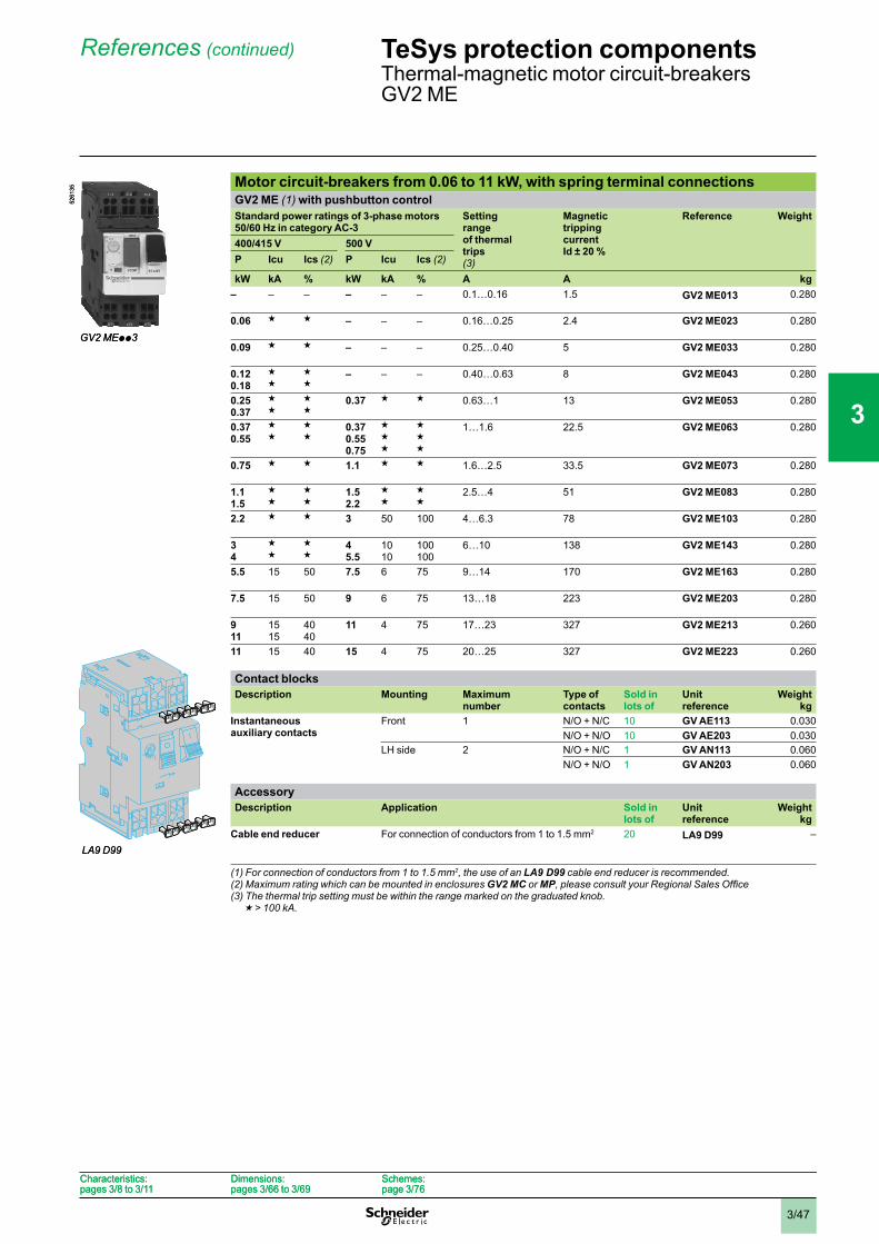
3/47
TeSys protection components Thermal-magnetic motor circuit-breakersGV2 ME
References (continued)
Motor circuit-breakers from 0.06 to 11 kW, with spring terminal connectionsGV2 ME (1) with pushbutton controlStandard power ratings of 3-phase motors 50/60 Hz in category AC-3
Settingrangeof thermal trips(3)
MagnetictrippingcurrentId ± 20 %
Reference Weight
400/415 V 500 VP Icu Ics (2) P Icu Ics (2)
kW kA % kW kA % A A kg– – – – – – 0.1…0.16 1.5 GV2 ME013 0.280
0.06 g g – – – 0.16…0.25 2.4 GV2 ME023 0.280
0.09 g g – – – 0.25…0.40 5 GV2 ME033 0.280
0.120.18
gg
gg
– – – 0.40…0.63 8 GV2 ME043 0.280
0.250.37
gg
gg
0.37 g g 0.63…1 13 GV2 ME053 0.280
0.370.55
gg
gg
0.370.550.75
ggg
ggg
1…1.6 22.5 GV2 ME063 0.280
0.75 g g 1.1 g g 1.6…2.5 33.5 GV2 ME073 0.280
1.11.5
gg
gg
1.52.2
gg
gg
2.5…4 51 GV2 ME083 0.280
2.2 g g 3 50 100 4…6.3 78 GV2 ME103 0.280
34
gg
gg
45.5
1010
100100
6…10 138 GV2 ME143 0.280
5.5 15 50 7.5 6 75 9…14 170 GV2 ME163 0.280
7.5 15 50 9 6 75 13…18 223 GV2 ME203 0.280
911
1515
4040
11 4 75 17…23 327 GV2 ME213 0.260
11 15 40 15 4 75 20…25 327 GV2 ME223 0.260
Contact blocksDescription Mounting Maximum
numberType of contacts
Sold in lots of
Unitreference
Weightkg
Instantaneousauxiliary contacts
Front 1 N/O + N/C 10 GV AE113 0.030N/O + N/O 10 GV AE203 0.030
LH side 2 N/O + N/C 1 GV AN113 0.060N/O + N/O 1 GV AN203 0.060
AccessoryDescription Application Sold in
lots ofUnitreference
Weight kg
Cable end reducer For connection of conductors from 1 to 1.5 mm2 20 LA9 D99 –
(1) For connection of conductors from 1 to 1.5 mm2, the use of an LA9 D99 cable end reducer is recommended.(2) Maximum rating which can be mounted in enclosures GV2 MC or MP(3) The thermal trip setting must be within the range marked on the graduated knob.
g > 100 kA.
GV2 MEpp3
5261
35
GV2 MEpp3
5261
35
LA9 D99LA9 D99
Characteristics:pages 3/8 to 3/11
Dimensions:pages 3/66 to 3/69
Schemes:page 3/76
Characteristics:pages 3/8 to 3/11
Dimensions:pages 3/66 to 3/69
Schemes:page 3/76
1
2
3
4
5
6
7
8
9
10
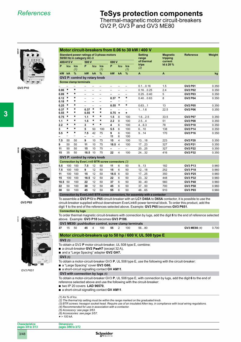
3/48
References
Motor circuit-breakers from 0.06 to 30 kW / 400 VStandard power ratings of 3-phase motors50/60 Hz in category AC-3
Settingrangeof thermal trips(2)
MagnetictrippingcurrentId ± 20 %
Reference Weight
400/415 V 500 V 690 VP Icu Ics
(1)P Icu Ics
(1)P Icu Ics
(1)kW kA % kW kA % kW kA % A A kgGV2 P: control by rotary knobScrew clamp terminals
– – – – – – – – – 0.1…0.16 1.5 GV2 P01 0.3500.06 g g – – – – – – 0.16…0.25 2.4 GV2 P02 0.3500.09 g g – – – – – – 0.25…0.40 5 GV2 P03 0.3500.120.18
gg
gg
––
––
––
0.37–
g–
g–
0.40…0.63 8 GV2 P04 0.350
0.25 g g – – – 0.55 g g 0.63…1 13 GV2 P05 0.3500.370.55
gg
gg
0.370.55
gg
gg
–0.75
–g
–g
1…1.6 22.5 GV2 P06 0.350
0.75 g g 1.1 g g 1.5 8 100 1.6…2.5 33.5 GV2 P07 0.3501.1 g g 1.5 g g 2.2 8 100 2.5…4 51 GV2 P08 0.3502.2 g g 3 g g 4 6 100 4…6.3 78 GV2 P10 0.3503 g g 5 50 100 5.5 6 100 6…10 138 GV2 P14 0.3505.5–
g–
g–
7.5–
42–
75–
911
66
100100
9…14 170 GV2 P16 0.350
7.5 50 50 9 10 75 15 4 100 13…18 223 GV2 P20 0.3509 50 50 11 10 75 18.5 4 100 17…23 327 GV2 P21 0.35011 50 50 15 10 75 – – – 20…25 327 GV2 P22 0.35015 35 50 18.5 10 75 22 4 100 24…32 416 GV2 P32 0.350
GV3 P: control by rotary knobConnection by EverLink® BTR screw connectors (3)
5.5 100 100 7.5 12 50 11 6 50 9…13 182 GV3 P13 0.9607.5 100 100 9 12 50 15 6 50 12…18 252 GV3 P18 0.96011 100 100 15 12 50 18.5 6 50 17…25 350 GV3 P25 0.96015 100 100 18.5 12 50 22 6 50 23…32 448 GV3 P32 0.96018.5 50 100 22 12 50 37 6 50 30…40 560 GV3 P40 0.96022 50 100 30 12 50 45 6 50 37…50 700 GV3 P50 0.96030 50 100 45 12 50 55 6 50 48…65 910 GV3 P65 0.960Connection by EverLink® BTR screw connectors, for assembly with a contactor
To assemble a GV3 P13 to P65 circuit-breaker with an LC1 D40A to D65A contactor, it is possible to use thecircuit-breaker supplied without downstream EverLink® power terminal block. To order this product, add thedigit 1 to the end of the references selected above. Example: GV3 P65 becomes GV3 P651.Connection by lugs
To order thermal magnetic circuit-breakers with connection by lugs, add the digit 6 to the end of reference selectedabove. Example: GV3 P18 becomes GV3 P186.GV3 ME80: pushbutton control, screw clamp terminals
37 15 50 45 4 100 55 2 100 56…80 GV3 ME80 (4) 0.700
Motor circuit-breakers up to 50 hp / 600 V, UL 508 type EGV2 (5)
To obtain a GV2 P motor circuit-breaker, UL 508 type E, combine:a circuit-breaker GV2 PppH7 (except 32 A),and a “Large Spacing” adapter GV2 GH7.
bbGV3 (6)
To obtain a motor-circuit-breaker GV3 P, UL 508 type E, use the following with the circuit-breaker:a “Large Spacing” cover GV3 G66,a short-circuit signalling contact GV AM11.
bbGV3 with connection by lugs (6)
To obtain a motor-circuit-breaker GV3 P, UL 508 type E, with connection by lugs, add the digit 6 to the end ofreference selected above and use the following with the circuit-breaker:
two IP 20 covers LAD 96570,a short-circuit signalling contact GV AM11.
bb
(1) As % of Icu.(2) The thermal trip setting must be within the range marked on the graduated knob.(3) BTR screws: hexagon socket head. Require use of an insulated Allen key, in compliance with local wiring regulations.(4) Recommended for use in association with a contactor.(5) Accessory: see page 3/63.(6) Accessories: see page 3/57.g > 100 kA.
GV2 P10
5261
37
GV2 P10
5261
37
GV3 P65
5261
39
GV3 P65
5261
39TeSys protection componentsThermal-magnetic motor circuit-breakersGV2 P, GV3 P and GV3 ME80
GV3 P651
5261
40
Characteristics:pages 3/8 to 3/13
Dimensions:pages 3/66 to 3/72
Characteristics:pages 3/8 to 3/13
Dimensions:pages 3/66 to 3/72
1
2
3
4
5
6
7
8
9
10
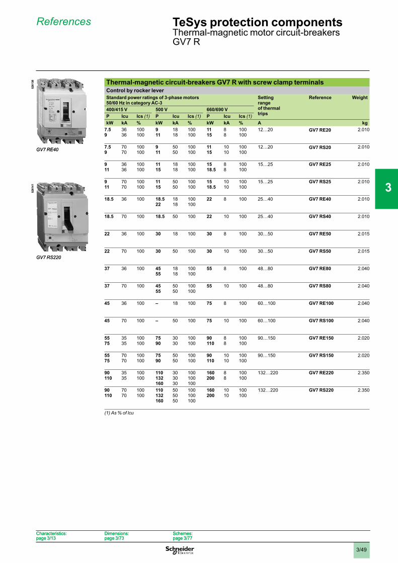
3/49
References
Thermal-magnetic circuit-breakers GV7 R with screw clamp terminalsControl by rocker leverStandard power ratings of 3-phase motors 50/60 Hz in category AC-3
Settingrangeof thermal trips
Reference Weight
400/415 V 500 V 660/690 VP Icu Ics (1) P Icu Ics (1) P Icu Ics (1)kW kA % kW kA % kW kA % A kg
7.59
3636
100100
911
1818
100100
1115
88
100100
12…20 GV7 RE20 2.010
7.59
7070
100100
911
5050
100100
1115
1010
100100
12…20 GV7 RS20 2.010
911
3636
100100
1115
1818
100100
1518.5
88
100100
15…25 GV7 RE25 2.010
911
7070
100100
1115
5050
100100
1518.5
1010
100100
15…25 GV7 RS25 2.010
18.5 36 100 18.522
1818
100100
22 8 100 25…40 GV7 RE40 2.010
18.5 70 100 18.5 50 100 22 10 100 25…40 GV7 RS40 2.010
22 36 100 30 18 100 30 8 100 30…50 GV7 RE50 2.015
22 70 100 30 50 100 30 10 100 30…50 GV7 RS50 2.015
37 36 100 4555
1818
100100
55 8 100 48…80 GV7 RE80 2.040
37 70 100 4555
5050
100100
55 10 100 48…80 GV7 RS80 2.040
45 36 100 – 18 100 75 8 100 60…100 GV7 RE100 2.040
45 70 100 – 50 100 75 10 100 60…100 GV7 RS100 2.040
5575
3535
100100
7590
3030
100100
90110
88
100100
90…150 GV7 RE150 2.020
5575
7070
100100
7590
5050
100100
90110
1010
100100
90…150 GV7 RS150 2.020
90110
3535
100100
110132160
303030
100100100
160200
88
100100
132…220 GV7 RE220 2.350
90110
7070
100100
110132160
505050
100100100
160200
1010
100100
132…220 GV7 RS220 2.350
(1) As % of lcu
GV7 RE40
5261
38
GV7 RE40
5261
38
GV7 RS220
5261
41
GV7 RS220
5261
41
TeSys protection components Thermal-magnetic motor circuit-breakersGV7 R
Characteristics:page 3/13
Dimensions:page 3/73
Schemes:page 3/77
Characteristics:page 3/13
Dimensions:page 3/73
Schemes:page 3/77
1
2
3
4
5
6
7
8
9
10
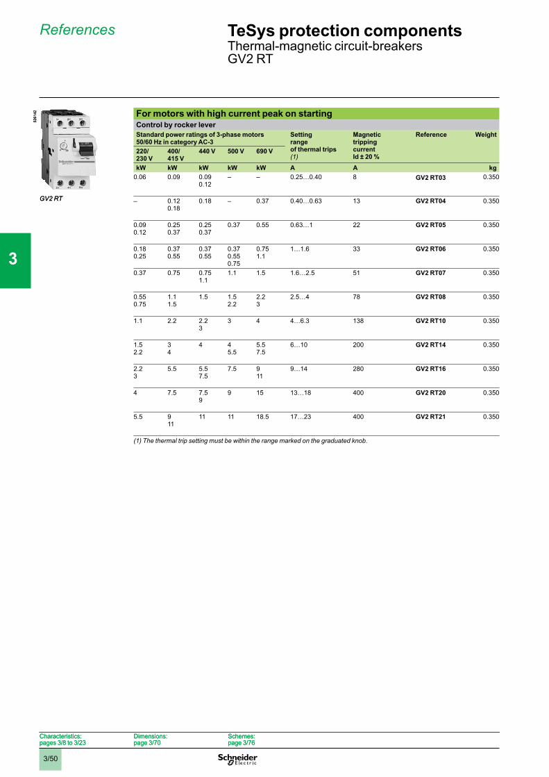
3/50
References
For motors with high current peak on startingControl by rocker leverStandard power ratings of 3-phase motors 50/60 Hz in category AC-3
Settingrangeof thermal trips(1)
MagnetictrippingcurrentId ± 20 %
Reference Weight
220/230 V
400/415 V
440 V 500 V 690 V
kW kW kW kW kW A A kg0.06 0.09 0.09
0.12– – 0.25…0.40 8 GV2 RT03 0.350
– 0.120.18
0.18 – 0.37 0.40…0.63 13 GV2 RT04 0.350
0.090.12
0.250.37
0.250.37
0.37 0.55 0.63…1 22 GV2 RT05 0.350
0.180.25
0.370.55
0.370.55
0.370.550.75
0.751.1
1…1.6 33 GV2 RT06 0.350
0.37 0.75 0.751.1
1.1 1.5 1.6…2.5 51 GV2 RT07 0.350
0.550.75
1.11.5
1.5 1.52.2
2.23
2.5…4 78 GV2 RT08 0.350
1.1 2.2 2.23
3 4 4…6.3 138 GV2 RT10 0.350
1.52.2
34
4 45.5
5.57.5
6…10 200 GV2 RT14 0.350
2.23
5.5 5.57.5
7.5 911
9…14 280 GV2 RT16 0.350
4 7.5 7.59
9 15 13…18 400 GV2 RT20 0.350
5.5 911
11 11 18.5 17…23 400 GV2 RT21 0.350
(1) The thermal trip setting must be within the range marked on the graduated knob.
GV2 RT
5261
42
GV2 RT
5261
42TeSys protection components Thermal-magnetic circuit-breakersGV2 RT
Characteristics:pages 3/8 to 3/23
Dimensions:page 3/70
Schemes:page 3/76
Characteristics:pages 3/8 to 3/23
Dimensions:page 3/70
Schemes:page 3/76
1
2
3
4
5
6
7
8
9
10
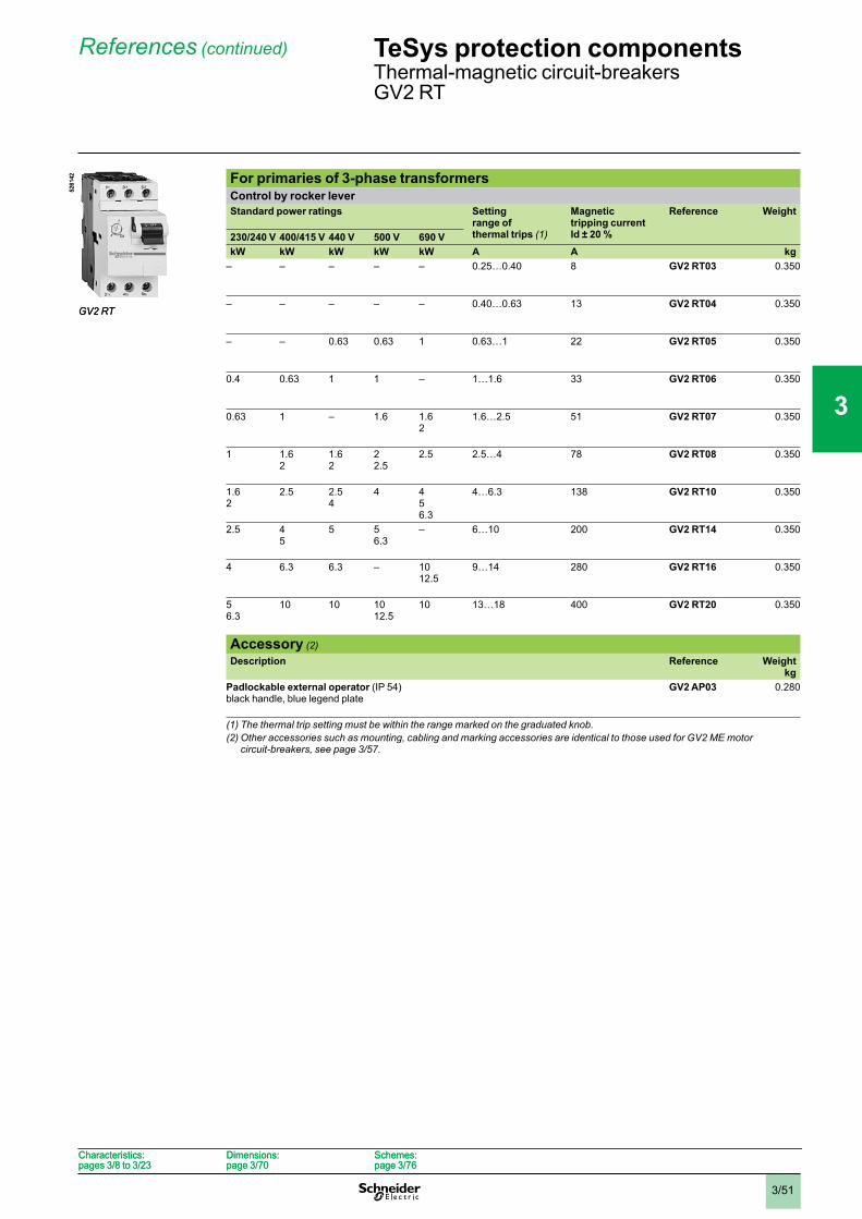
3/51
References (continued)
For primaries of 3-phase transformersControl by rocker leverStandard power ratings Setting
range of thermal trips (1)
Magnetictripping currentId ± 20 %
Reference Weight
230/240 V 400/415 V 440 V 500 V 690 VkW kW kW kW kW A A kg
– – – – – 0.25…0.40 8 GV2 RT03 0.350
– – – – – 0.40…0.63 13 GV2 RT04 0.350
– – 0.63 0.63 1 0.63…1 22 GV2 RT05 0.350
0.4 0.63 1 1 – 1…1.6 33 GV2 RT06 0.350
0.63 1 – 1.6 1.62
1.6…2.5 51 GV2 RT07 0.350
1 1.62
1.62
22.5
2.5 2.5…4 78 GV2 RT08 0.350
1.62
2.5 2.54
4 456.3
4…6.3 138 GV2 RT10 0.350
2.5 45
5 56.3
– 6…10 200 GV2 RT14 0.350
4 6.3 6.3 – 1012.5
9…14 280 GV2 RT16 0.350
56.3
10 10 1012.5
10 13…18 400 GV2 RT20 0.350
Accessory (2)Description Reference Weight
kgPadlockable external operator (IP 54)black handle, blue legend plate
GV2 AP03 0.280
(1) The thermal trip setting must be within the range marked on the graduated knob.(2) Other accessories such as mounting, cabling and marking accessories are identical to those used for GV2 ME motor
circuit-breakers, see page 3/57.
GV2 RT
5261
42
GV2 RT
5261
42
TeSys protection components Thermal-magnetic circuit-breakersGV2 RT
Characteristics:pages 3/8 to 3/23
Dimensions:page 3/70
Schemes:page 3/76
Characteristics:pages 3/8 to 3/23
Dimensions:page 3/70
Schemes:page 3/76
1
2
3
4
5
6
7
8
9
10
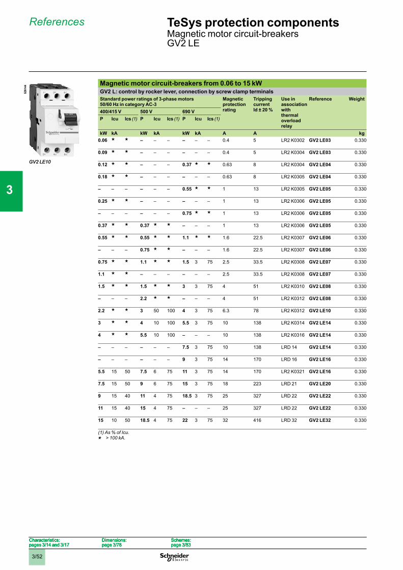
3/52
References
Magnetic motor circuit-breakers from 0.06 to 15 kWGV2 L: control by rocker lever, connection by screw clamp terminalsStandard power ratings of 3-phase motors50/60 Hz in category AC-3
Magneticprotectionrating
Tripping currentId ± 20 %
Use in associationwiththermaloverloadrelay
Reference Weight
400/415 V 500 V 690 VP Icu Ics (1) P Icu Ics (1) P Icu Ics (1)
kW kA kW kA kW kA A A kg0.06 g g – – – – – – 0.4 5 LR2 K0302 GV2 LE03 0.330
0.09 g g – – – – – – 0.4 5 LR2 K0304 GV2 LE03 0.330
0.12 g g – – – 0.37 g g 0.63 8 LR2 K0304 GV2 LE04 0.330
0.18 g g – – – – – – 0.63 8 LR2 K0305 GV2 LE04 0.330
– – – – – – 0.55 g g 1 13 LR2 K0305 GV2 LE05 0.330
0.25 g g – – – – – – 1 13 LR2 K0306 GV2 LE05 0.330
– – – – – – 0.75 g g 1 13 LR2 K0306 GV2 LE05 0.330
0.37 g g 0.37 g g – – – 1 13 LR2 K0306 GV2 LE05 0.330
0.55 g g 0.55 g g 1.1 g g 1.6 22.5 LR2 K0307 GV2 LE06 0.330
– – – 0.75 g g – – – 1.6 22.5 LR2 K0307 GV2 LE06 0.330
0.75 g g 1.1 g g 1.5 3 75 2.5 33.5 LR2 K0308 GV2 LE07 0.330
1.1 g g – – – – – – 2.5 33.5 LR2 K0308 GV2 LE07 0.330
1.5 g g 1.5 g g 3 3 75 4 51 LR2 K0310 GV2 LE08 0.330
– – – 2.2 g g – – – 4 51 LR2 K0312 GV2 LE08 0.330
2.2 g g 3 50 100 4 3 75 6.3 78 LR2 K0312 GV2 LE10 0.330
3 g g 4 10 100 5.5 3 75 10 138 LR2 K0314 GV2 LE14 0.330
4 g g 5.5 10 100 – – – 10 138 LR2 K0316 GV2 LE14 0.330
– – – – – – 7.5 3 75 10 138 LRD 14 GV2 LE14 0.330
– – – – – – 9 3 75 14 170 LRD 16 GV2 LE16 0.330
5.5 15 50 7.5 6 75 11 3 75 14 170 LR2 K0321 GV2 LE16 0.330
7.5 15 50 9 6 75 15 3 75 18 223 LRD 21 GV2 LE20 0.330
9 15 40 11 4 75 18.5 3 75 25 327 LRD 22 GV2 LE22 0.330
11 15 40 15 4 75 – – – 25 327 LRD 22 GV2 LE22 0.330
15 10 50 18.5 4 75 22 3 75 32 416 LRD 32 GV2 LE32 0.330
(1) As % of Icu.g > 100 kA.
GV2 LE10
5261
44
GV2 LE10
5261
44
Characteristics:pages 3/14 and 3/17
Dimensions:page 3/78
Schemes:page 3/83
Characteristics:pages 3/14 and 3/17
Dimensions:page 3/78
Schemes:page 3/83
Characteristics:pages 3/14 and 3/17
Dimensions:page 3/78
Schemes:page 3/83
Characteristics:pages 3/14 and 3/17
Dimensions:page 3/78
Schemes:page 3/83
TeSys protection componentsMagnetic motor circuit-breakersGV2 LE
1
2
3
4
5
6
7
8
9
10
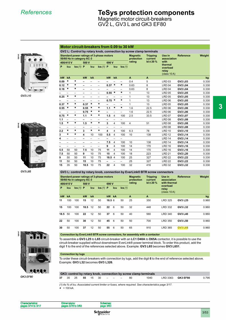
3/53
References
Motor circuit-breakers from 0.09 to 30 kWGV2 L: Control by rotary knob, connection by screw clamp terminalsStandard power ratings of 3-phase motors50/60 Hz in category AC-3
Magneticprotectionrating
Tripping currentId ± 20 %
Use in associationwiththermaloverloadrelay(class 10 A)
Reference Weight
400/415 V 500 V 690 VP Icu Ics (1) P Icu Ics (1) P Icu Ics (1)
kW kA kW kA kW kA A A kg0.09 g g – – – – – – 0.4 5 LRD 03 GV2 L03 0.3300.12 g g – – – 0.37 g g 0.63 8 LRD 04 GV2 L04 0.3300.18 g g – – – – – – 0.63 8 LRD 04 GV2 L04 0.330– – – – – – 0.55 g g 1 13 LRD 05 GV2 L05 0.3300.25 g g – – – – – – 1 13 LRD 05 GV2 L05 0.330– – – – – – 0.75 g g 1 13 LRD 06 GV2 L05 0.3300.37 g g 0.37 g g – – – 1 13 LRD 05 GV2 L05 0.3300.55 g g 0.55 g g 1.1 g g 1.6 22.5 LRD 06 GV2 L06 0.330– – – 0.75 g g – – – 1.6 22.5 LRD 06 GV2 L06 0.3300.75 g g 1.1 g g 1.5 4 100 2.5 33.5 LRD 07 GV2 L07 0.3301.1 – – – – – – – – LRD 08 GV2 L08 0.3301.5 g g 1.5 g g 3 4 100 4 51 LRD 08 GV2 L08 0.330– – – – – – – – – LRD 08 GV2 L08 0.3302.2 g g 3 g g 4 4 100 6.3 78 LRD 10 GV2 L10 0.3303 g g 4 10 100 5.5 4 100 10 138 LRD 12 GV2 L14 0.3304 – – – – – – – – LRD 14 GV2 L14 0.330– – – – – – 7.5 4 100 10 138 LRD 14 GV2 L14 0.330– – – – – – 9 4 100 14 170 LRD 16 GV2 L16 0.3305.5 50 50 7.5 10 75 11 4 100 14 170 LRD 16 GV2 L16 0.3307.5 50 50 9 10 75 15 4 100 18 223 LRD 21 GV2 L20 0.3309 50 50 11 10 75 18.5 4 100 25 327 LRD 22 GV2 L22 0.33011 50 50 15 10 75 – – – 25 327 LRD 22 GV2 L22 0.33015 35 50 18.5 10 75 22 4 100 32 416 LRD 32 GV2 L32 0.330
GV3 L: control by rotary knob, connection by EverLink® BTR screw connectorsStandard power ratings of 3-phase motors50/60 Hz in category AC-3
Magneticprotectionrating
Tripping currentId ± 20 %
Use in associationwith thermal overloadrelay(class 10 A)
Reference Weight
400/415 V 500 V 690 VP Icu Ics (1) P Icu Ics (1) P Icu Ics (1)
kW kA kW kA kW kA A A kg11 100 100 15 12 50 18.5 6 50 25 350 LRD 325 GV3 L25 0.960
15 100 100 18.5 12 50 22 6 50 32 448 LRD 332 GV3 L32 0.960
18.5 50 100 22 12 50 37 6 50 40 560 LRD 340 GV3 L40 0.960
22 50 100 30 12 50 45 6 50 50 700 LRD 350 GV3 L50 0.960
30 50 100 37 12 50 55 6 50 65 910 LRD 365 GV3 L65 0.960
Connection by EverLink® BTR screw connectors, for assembly with a contactor
To assemble a GV3 L25 to L65 circuit-breaker with an LC1 D40A to D65A contactor, it is possible to use thecircuit-breaker supplied without downstream EverLink® power terminal block. To order this product, add thedigit 1 to the end of the references selected above. Example: GV3 L65 becomes GV3 L651.
Connection by lugsTo order these circuit-breakers with connection by lugs, add the digit 6 to the end of reference selected above.Example: GV3 L32 becomes GV3 L326.
GK3: control by rotary knob, connection by screw clamp terminals37 35 25 55 15 30 – – – 80 1040 LRD 3363 GK3 EF80 0.795
(1) As % of Icu. Associated current limiter or fuses, where required. See characteristics page 3/17.g > 100 kA.
GV2 L10
5261
45
GV2 L10
5261
45
GV3 L65
5261
46
GV3 L65
5261
46
GK3 EF80
5261
47
GK3 EF80
5261
47
Characteristics:pages 3/14 to 3/17
Dimensions:pages 3/78 to 3/83
Schemes:page 3/83
Characteristics:pages 3/14 to 3/17
Dimensions:pages 3/78 to 3/83
Schemes:page 3/83
Characteristics:pages 3/14 to 3/17
Dimensions:pages 3/78 to 3/83
Schemes:page 3/83
Characteristics:pages 3/14 to 3/17
Dimensions:pages 3/78 to 3/83
Schemes:page 3/83
TeSys protection componentsMagnetic motor circuit-breakersGV2 L, GV3 L and GK3 EF80
1
2
3
4
5
6
7
8
9
10
SESA47545
강조
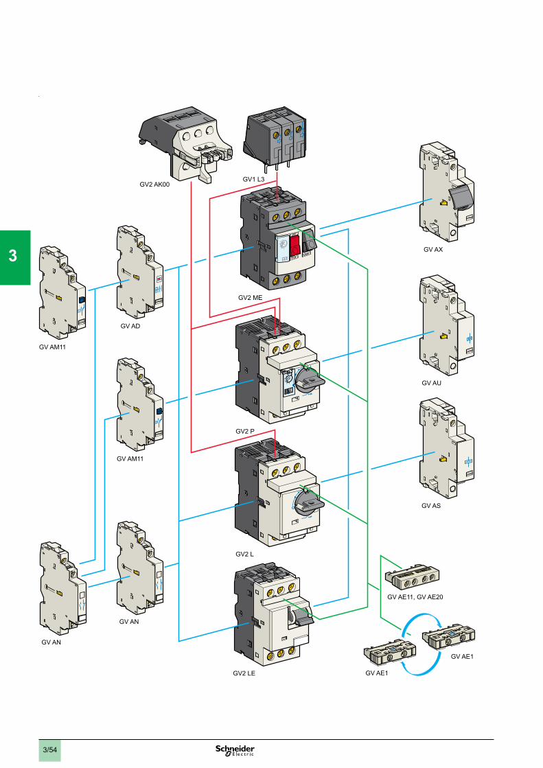
3/54
GV2 AK00GV1 L3
GV AD
GV AM11
GV AM11
GV AN
GV AN
GV2 P
GV2 ME
GV AX
GV AU
GV AS
GV AE1
GV AE1
GV AE11, GV AE20
GV2 L
GV2 LE
Pg 2
1
2
3
4
5
6
7
8
9
10
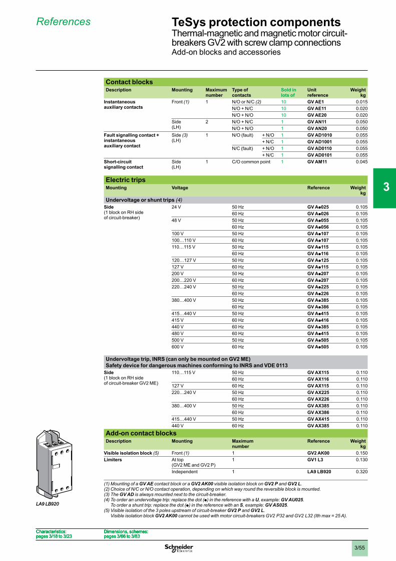
3/55
Contact blocksDescription Mounting Maximum
numberType of contacts
Sold in lots of
Unitreference
Weightkg
Instantaneousauxiliary contacts
Front (1) 1 N/O or N/C (2) 10 GV AE1 0.015N/O + N/C 10 GV AE11 0.020N/O + N/O 10 GV AE20 0.020
Side(LH)
2 N/O + N/C 1 GV AN11 0.050N/O + N/O 1 GV AN20 0.050
Fault signalling contact + instantaneousauxiliary contact
Side (3)(LH)
1 N/O (fault) + N/O 1 GV AD1010 0.055+ N/C 1 GV AD1001 0.055
N/C (fault) + N/O 1 GV AD0110 0.055+ N/C 1 GV AD0101 0.055
Short-circuitsignalling contact
Side(LH)
1 C/O common point 1 GV AM11 0.045
Electric tripsMounting Voltage Reference Weight
kgUndervoltage or shunt trips (4)
Side(1 block on RH sideof circuit-breaker)
24 V 50 Hz GV Ap025 0.10560 Hz GV Ap026 0.105
48 V 50 Hz GV Ap055 0.10560 Hz GV Ap056 0.105
100 V 50 Hz GV Ap107 0.105100…110 V 60 Hz GV Ap107 0.105110…115 V 50 Hz GV Ap115 0.105
60 Hz GV Ap116 0.105120…127 V 50 Hz GV Ap125 0.105127 V 60 Hz GV Ap115 0.105200 V 50 Hz GV Ap207 0.105200…220 V 60 Hz GV Ap207 0.105220…240 V 50 Hz GV Ap225 0.105
60 Hz GV Ap226 0.105380…400 V 50 Hz GV Ap385 0.105
60 Hz GV Ap386 0.105415…440 V 50 Hz GV Ap415 0.105415 V 60 Hz GV Ap416 0.105440 V 60 Hz GV Ap385 0.105480 V 60 Hz GV Ap415 0.105500 V 50 Hz GV Ap505 0.105600 V 60 Hz GV Ap505 0.105
Undervoltage trip, INRS (can only be mounted on GV2 ME)Safety device for dangerous machines conforming to INRS and VDE 0113
Side(1 block on RH sideof circuit-breaker GV2 ME)
110…115 V 50 Hz GV AX115 0.11060 Hz GV AX116 0.110
127 V 60 Hz GV AX115 0.110220…240 V 50 Hz GV AX225 0.110
60 Hz GV AX226 0.110380…400 V 50 Hz GV AX385 0.110
60 Hz GV AX386 0.110415…440 V 50 Hz GV AX415 0.110440 V 60 Hz GV AX385 0.110
Add-on contact blocksDescription Mounting Maximum
numberReference Weight
kgVisible isolation block (5) Front (1) 1 GV2 AK00 0.150Limiters At top
(GV2 ME and GV2 P)1 GV1 L3 0.130
Independent 1 LA9 LB920 0.320
(1) Mounting of a GV AE contact block or a GV2 AK00 visible isolation block on GV2 P and GV2 L.(2) Choice of N/C or N/O contact operation, depending on which way round the reversible block is mounted.(3) The GV AD is always mounted next to the circuit-breaker.(4) To order an undervoltage trip: replace the dot (p) in the reference with a U, example: GV AU025.
To order a shunt trip: replace the dot (p) in the reference with an S, example: GV AS025.(5) Visible isolation of the 3 poles upstream of circuit-breaker GV2 P and GV2 L.
Visible isolation block GV2 AK00 cannot be used with motor circuit-breakers GV2 P32 and GV2 L32 (Ith max = 25 A).
LA9 LB920LA9 LB920
Characteristics:pages 3/18 to 3/23
Dimensions, schemes:pages 3/66 to 3/83
Characteristics:pages 3/18 to 3/23
Dimensions, schemes:pages 3/66 to 3/83
Characteristics:pages 3/18 to 3/23
Dimensions, schemes:pages 3/66 to 3/83
Characteristics:pages 3/18 to 3/23
Dimensions, schemes:pages 3/66 to 3/83
References TeSys protection componentsThermal-magnetic and magnetic motor circuit-breakers GV2 with screw clamp connectionsAdd-on blocks and accessories
1
2
3
4
5
6
7
8
9
10
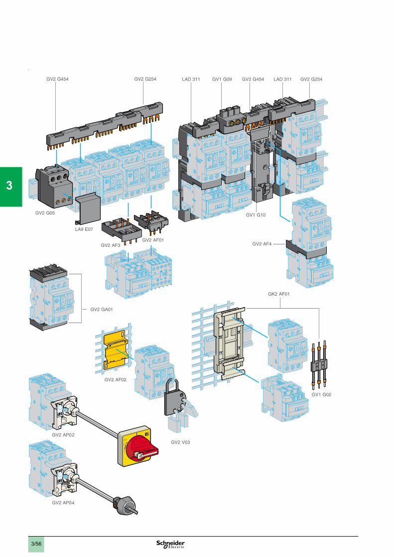
3/56
O
TRIP.
RESET
1
2
3
4
5
6
7
8
9
10
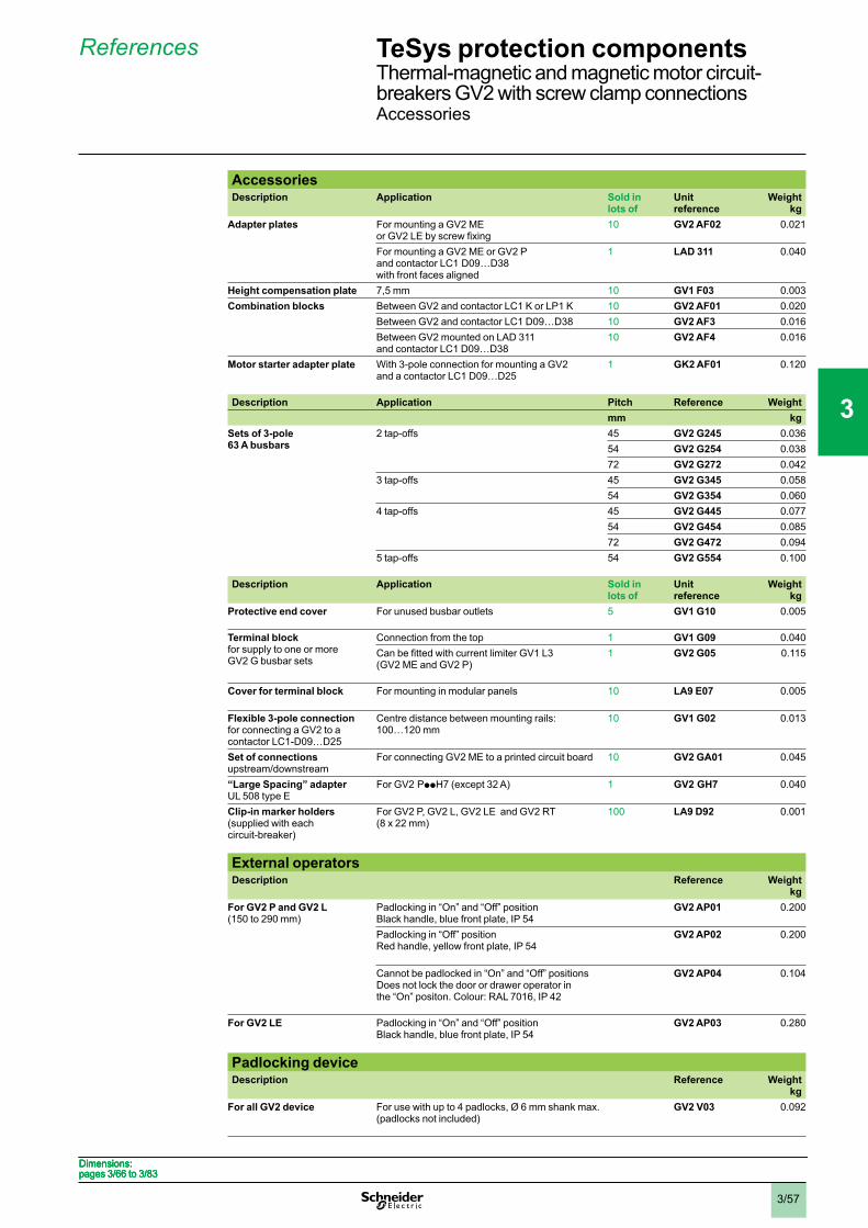
3/57
AccessoriesDescription Application Sold in
lots of Unitreference
Weightkg
Adapter plates For mounting a GV2 ME 10 GV2 AF02 0.021
For mounting a GV2 ME or GV2 Pand contactor LC1 D09…D38with front faces aligned
1 LAD 311 0.040
Height compensation plate 7,5 mm 10 GV1 F03 0.003Combination blocks Between GV2 and contactor LC1 K or LP1 K 10 GV2 AF01 0.020
Between GV2 and contactor LC1 D09…D38 10 GV2 AF3 0.016Between GV2 mounted on LAD 311and contactor LC1 D09…D38
10 GV2 AF4 0.016
Motor starter adapter plate With 3-pole connection for mounting a GV2and a contactor LC1 D09…D25
1 GK2 AF01 0.120
Description Application Pitch Reference Weightmm kg
Sets of 3-pole 63 A busbars
2 tap-offs 45 GV2 G245 0.03654 GV2 G254 0.03872 GV2 G272 0.042
3 tap-offs 45 GV2 G345 0.05854 GV2 G354 0.060
4 tap-offs 45 GV2 G445 0.07754 GV2 G454 0.08572 GV2 G472 0.094
5 tap-offs 54 GV2 G554 0.100
Description Application Sold in lots of
Unitreference
Weightkg
Protective end cover For unused busbar outlets 5 GV1 G10 0.005
Terminal block for supply to one or moreGV2 G busbar sets
Connection from the top 1 GV1 G09 0.040
(GV2 ME and GV2 P)1 GV2 G05 0.115
Cover for terminal block For mounting in modular panels 10 LA9 E07 0.005
Flexible 3-pole connection for connecting a GV2 to acontactor LC1-D09…D25
Centre distance between mounting rails:100…120 mm
10 GV1 G02 0.013
Set of connections upstream/downstream
For connecting GV2 ME to a printed circuit board 10 GV2 GA01 0.045
“Large Spacing” adapterUL 508 type E
For GV2 PppH7 (except 32 A) 1 GV2 GH7 0.040
Clip-in marker holders (supplied with eachcircuit-breaker)
For GV2 P, GV2 L, GV2 LE and GV2 RT(8 x 22 mm)
100 LA9 D92 0.001
External operatorsDescription Reference Weight
kgFor GV2 P and GV2 L(150 to 290 mm)
Padlocking in “On” and “Off” positionBlack handle, blue front plate, IP 54
GV2 AP01 0.200
Padlocking in “Off” positionRed handle, yellow front plate, IP 54
GV2 AP02 0.200
Cannot be padlocked in “On” and “Off” positionsDoes not lock the door or drawer operator inthe “On” positon. Colour: RAL 7016, IP 42
GV2 AP04 0.104
For GV2 LE Padlocking in “On” and “Off” positionBlack handle, blue front plate, IP 54
GV2 AP03 0.280
Padlocking deviceDescription Reference Weight
kgFor all GV2 device For use with up to 4 padlocks, Ø 6 mm shank max.
(padlocks not included)GV2 V03 0.092
Dimensions:pages 3/66 to 3/83Dimensions:pages 3/66 to 3/83Dimensions:pages 3/66 to 3/83Dimensions:pages 3/66 to 3/83
References TeSys protection componentsThermal-magnetic and magnetic motor circuit-breakers GV2 with screw clamp connectionsAccessories
1
2
3
4
5
6
7
8
9
10
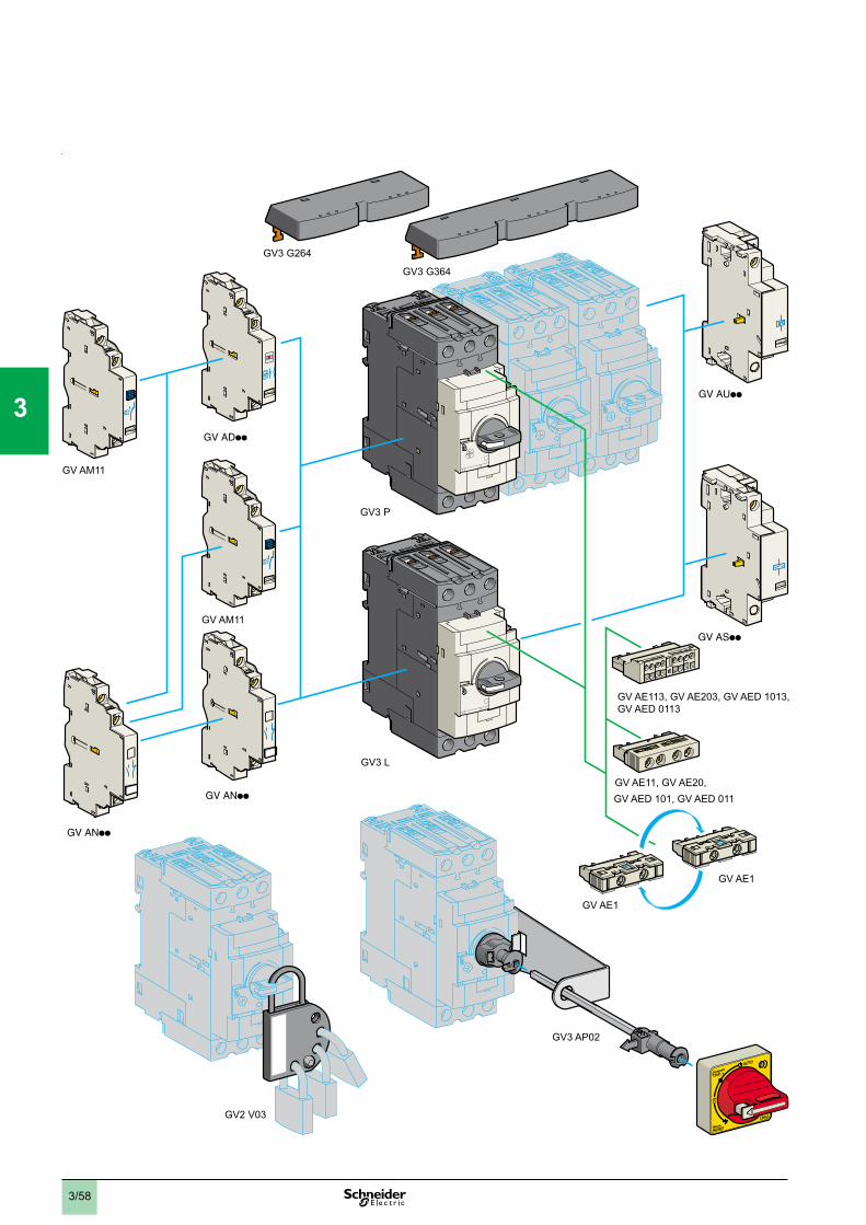
3/58
GV AM11
GV AM11
GV AE1
GV AE1
GV AE11, GV AE20,
GV3 L
GV3 P
GV3 G364
GV AE113, GV AE203, GV AED 1013, GV AED 0113
GV AED 101, GV AED 011
GV2 V03
GV3 G264
GV3 AP02
1
2
3
4
5
6
7
8
9
10
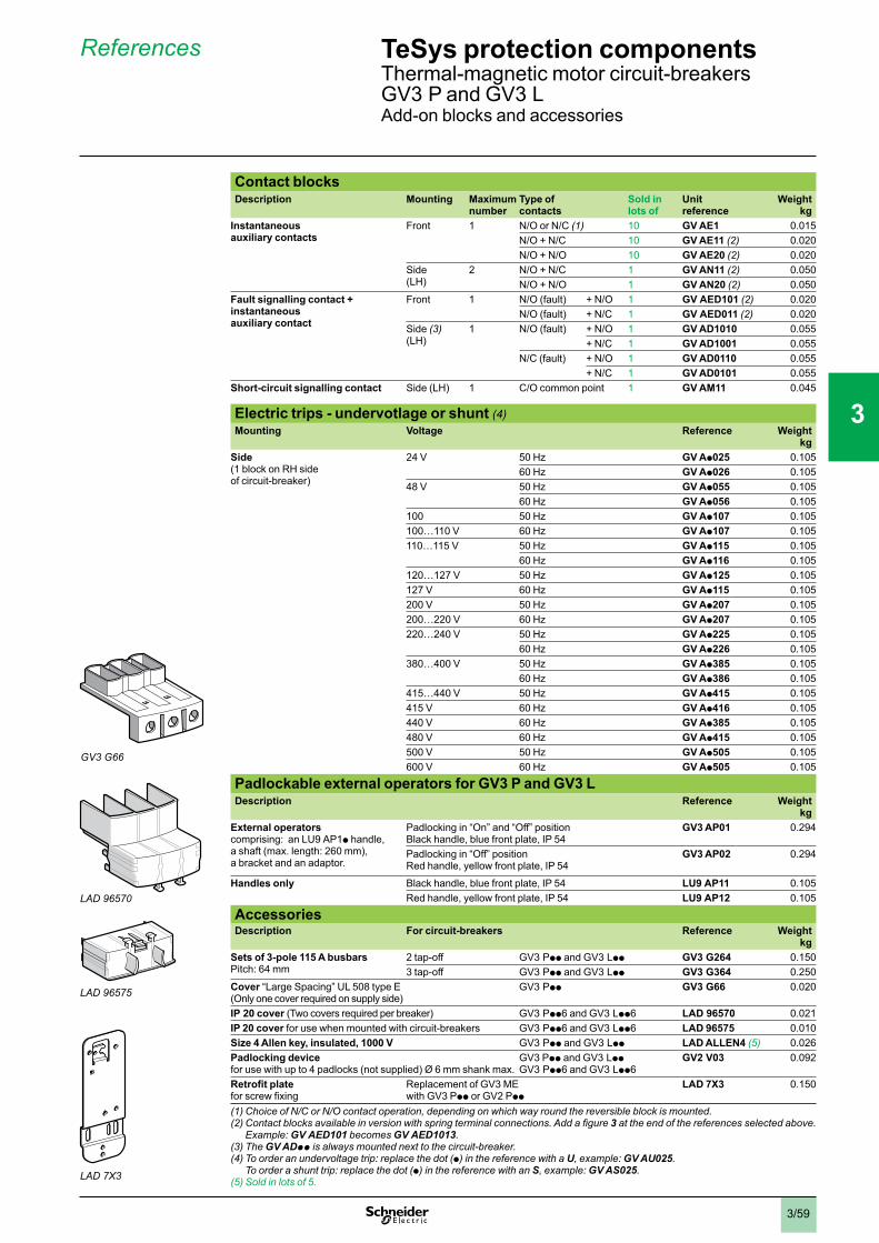
3/59
Contact blocksDescription Mounting Maximum
numberType of contacts
Sold in lots of
Unitreference
Weightkg
Instantaneousauxiliary contacts
Front 1 N/O or N/C (1) 10 GV AE1 0.015N/O + N/C 10 GV AE11 (2) 0.020N/O + N/O 10 GV AE20 (2) 0.020
Side(LH)
2 N/O + N/C 1 GV AN11 (2) 0.050N/O + N/O 1 GV AN20 (2) 0.050
Fault signalling contact + instantaneousauxiliary contact
Front 1 N/O (fault) + N/O 1 GV AED101 (2) 0.020N/O (fault) + N/C 1 GV AED011 (2) 0.020
Side (3)(LH)
1 N/O (fault) + N/O 1 GV AD1010 0.055+ N/C 1 GV AD1001 0.055
N/C (fault) + N/O 1 GV AD0110 0.055+ N/C 1 GV AD0101 0.055
Short-circuit signalling contact Side (LH) 1 C/O common point 1 GV AM11 0.045
Electric trips - undervotlage or shunt (4)Mounting Voltage Reference Weight
kgSide(1 block on RH sideof circuit-breaker)
24 V 50 Hz GV Ap025 0.10560 Hz GV Ap026 0.105
48 V 50 Hz GV Ap055 0.10560 Hz GV Ap056 0.105
100 50 Hz GV Ap107 0.105100…110 V 60 Hz GV Ap107 0.105110…115 V 50 Hz GV Ap115 0.105
60 Hz GV Ap116 0.105120…127 V 50 Hz GV Ap125 0.105127 V 60 Hz GV Ap115 0.105200 V 50 Hz GV Ap207 0.105200…220 V 60 Hz GV Ap207 0.105220…240 V 50 Hz GV Ap225 0.105
60 Hz GV Ap226 0.105380…400 V 50 Hz GV Ap385 0.105
60 Hz GV Ap386 0.105415…440 V 50 Hz GV Ap415 0.105415 V 60 Hz GV Ap416 0.105440 V 60 Hz GV Ap385 0.105480 V 60 Hz GV Ap415 0.105500 V 50 Hz GV Ap505 0.105600 V 60 Hz GV Ap505 0.105
Padlockable external operators for GV3 P and GV3 LDescription Reference Weight
kgExternal operatorscomprising: an LU9 AP1p handle,a shaft (max. length: 260 mm),a bracket and an adaptor.
Padlocking in “On” and “Off” positionBlack handle, blue front plate, IP 54
GV3 AP01 0.294
Padlocking in “Off” positionRed handle, yellow front plate, IP 54
GV3 AP02 0.294
Handles only Black handle, blue front plate, IP 54 LU9 AP11 0.105Red handle, yellow front plate, IP 54 LU9 AP12 0.105
AccessoriesDescription For circuit-breakers Reference Weight
kgSets of 3-pole 115 A busbarsPitch: 64 mm
2 tap-off GV3 Ppp and GV3 Lpp GV3 G264 0.1503 tap-off GV3 Ppp and GV3 Lpp GV3 G364 0.250
Cover “Large Spacing” UL 508 type E(Only one cover required on supply side)
GV3 Ppp GV3 G66 0.020
IP 20 cover (Two covers required per breaker) GV3 Ppp6 and GV3 Lpp6 LAD 96570 0.021IP 20 cover for use when mounted with circuit-breakers GV3 Ppp6 and GV3 Lpp6 LAD 96575 0.010Size 4 Allen key, insulated, 1000 V GV3 Ppp and GV3 Lpp LAD ALLEN4 (5) 0.026Padlocking devicefor use with up to 4 padlocks (not supplied) Ø 6 mm shank max.
GV3 Ppp and GV3 LppGV3 Ppp6 and GV3 Lpp6
GV2 V03 0.092
Replacement of GV3 MEwith GV3 Ppp or GV2 Ppp
LAD 7X3 0.150
(1) Choice of N/C or N/O contact operation, depending on which way round the reversible block is mounted.3 at the end of the references selected above.
Example: GV AED101 becomes GV AED1013.(3) The GV ADpp is always mounted next to the circuit-breaker.(4) To order an undervoltage trip: replace the dot (p) in the reference with a U, example: GV AU025.
To order a shunt trip: replace the dot (p) in the reference with an S, example: GV AS025.(5) Sold in lots of 5.
References TeSys protection componentsThermal-magnetic motor circuit-breakers GV3 P and GV3 LAdd-on blocks and accessories
GV3 G66
LAD 96570
LAD 96575
LAD 7X3
1
2
3
4
5
6
7
8
9
10
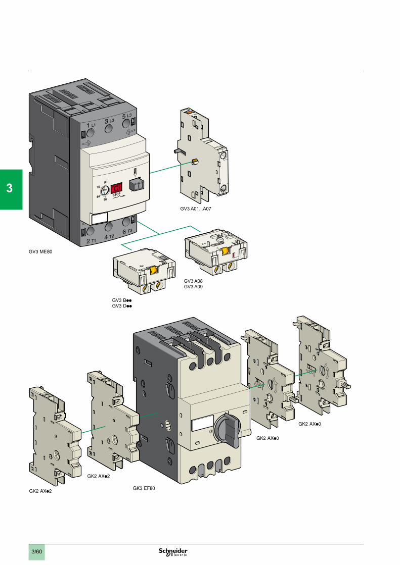
3/60
GV3 A08GV3 A09
GV3 A01...A07
1
2
3
4
5
6
7
8
9
10
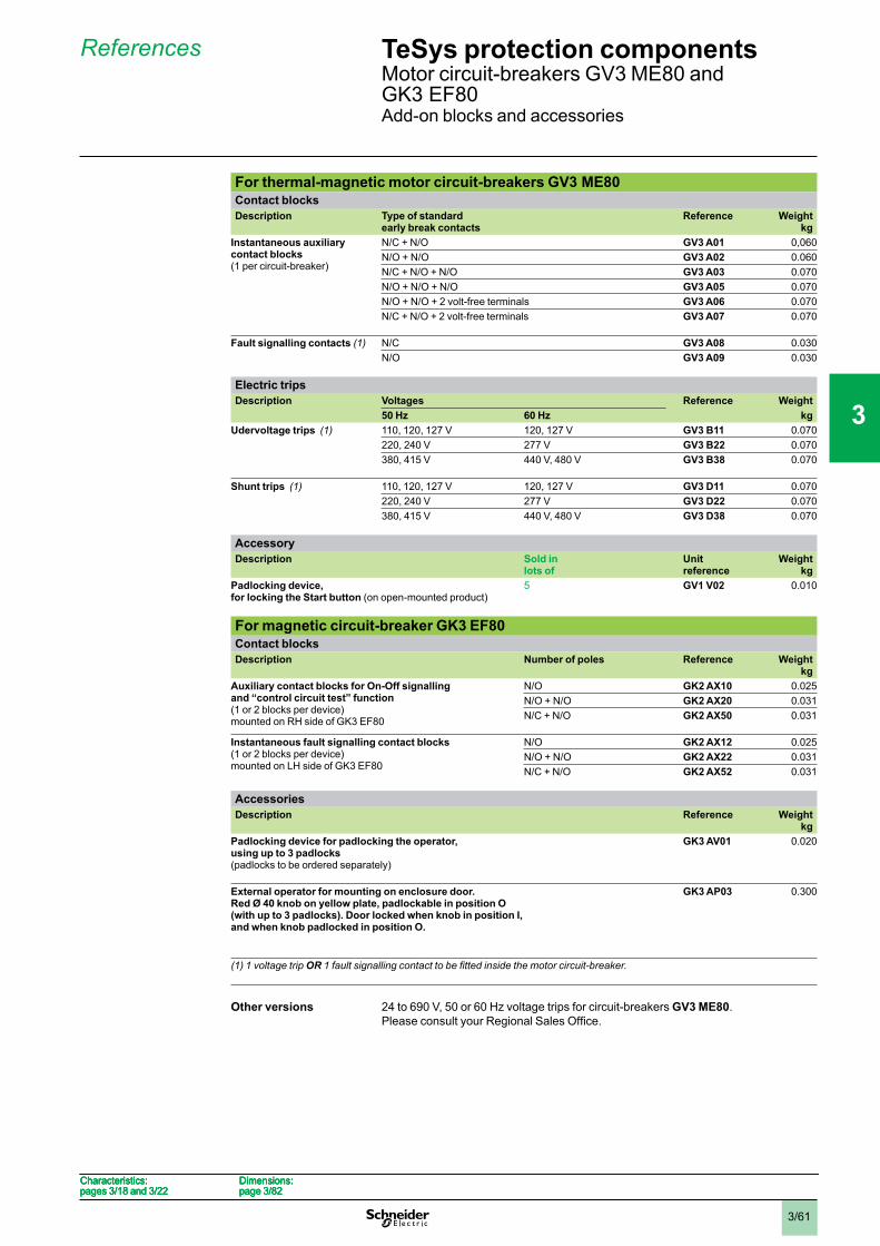
3/61
For thermal-magnetic motor circuit-breakers GV3 ME80Contact blocksDescription Type of standard
early break contactsReference Weight
kgInstantaneous auxiliary contact blocks(1 per circuit-breaker)
N/C + N/O GV3 A01 0,060N/O + N/O GV3 A02 0.060N/C + N/O + N/O GV3 A03 0.070N/O + N/O + N/O GV3 A05 0.070N/O + N/O + 2 volt-free terminals GV3 A06 0.070N/C + N/O + 2 volt-free terminals GV3 A07 0.070
Fault signalling contacts (1) N/C GV3 A08 0.030N/O GV3 A09 0.030
Electric tripsDescription Voltages Reference Weight
50 Hz 60 Hz kgUdervoltage trips (1) 110, 120, 127 V 120, 127 V GV3 B11 0.070
220, 240 V 277 V GV3 B22 0.070380, 415 V 440 V, 480 V GV3 B38 0.070
Shunt trips (1) 110, 120, 127 V 120, 127 V GV3 D11 0.070220, 240 V 277 V GV3 D22 0.070380, 415 V 440 V, 480 V GV3 D38 0.070
AccessoryDescription Sold in
lots ofUnitreference
Weightkg
Padlocking device, for locking the Start button (on open-mounted product)
5 GV1 V02 0.010
For magnetic circuit-breaker GK3 EF80Contact blocksDescription Number of poles Reference Weight
kgAuxiliary contact blocks for On-Off signalling and “control circuit test” function (1 or 2 blocks per device)mounted on RH side of GK3 EF80
N/O GK2 AX10 0.025N/O + N/O GK2 AX20 0.031N/C + N/O GK2 AX50 0.031
Instantaneous fault signalling contact blocks (1 or 2 blocks per device)mounted on LH side of GK3 EF80
N/O GK2 AX12 0.025N/O + N/O GK2 AX22 0.031N/C + N/O GK2 AX52 0.031
AccessoriesDescription Reference Weight
kgPadlocking device for padlocking the operator, using up to 3 padlocks(padlocks to be ordered separately)
GK3 AV01 0.020
External operator for mounting on enclosure door.Red Ø 40 knob on yellow plate, padlockable in position O (with up to 3 padlocks). Door locked when knob in position I, and when knob padlocked in position O.
GK3 AP03 0.300
(1) 1 voltage trip OR
Other versions 24 to 690 V, 50 or 60 Hz voltage trips for circuit-breakers GV3 ME80.
Characteristics:pages 3/18 and 3/22
Dimensions:page 3/82
Characteristics:pages 3/18 and 3/22
Dimensions:page 3/82
Characteristics:pages 3/18 and 3/22
Dimensions:page 3/82
Characteristics:pages 3/18 and 3/22
Dimensions:page 3/82
References TeSys protection componentsMotor circuit-breakers GV3 ME80 andGK3 EF80Add-on blocks and accessories
1
2
3
4
5
6
7
8
9
10
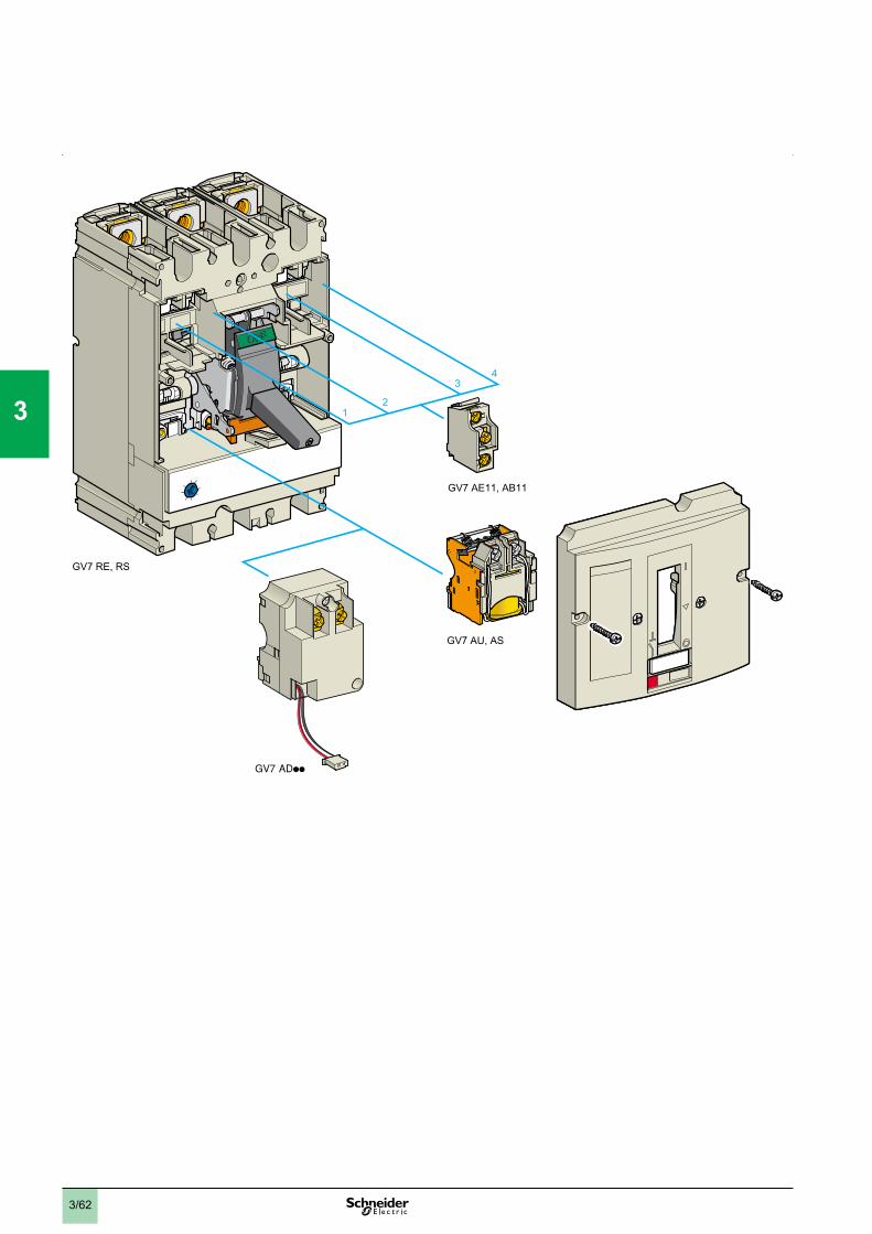
3/62
GV7 RE, RS
GV7 AE11, AB11
GV7 AU, AS
12
34
1
2
3
4
5
6
7
8
9
10
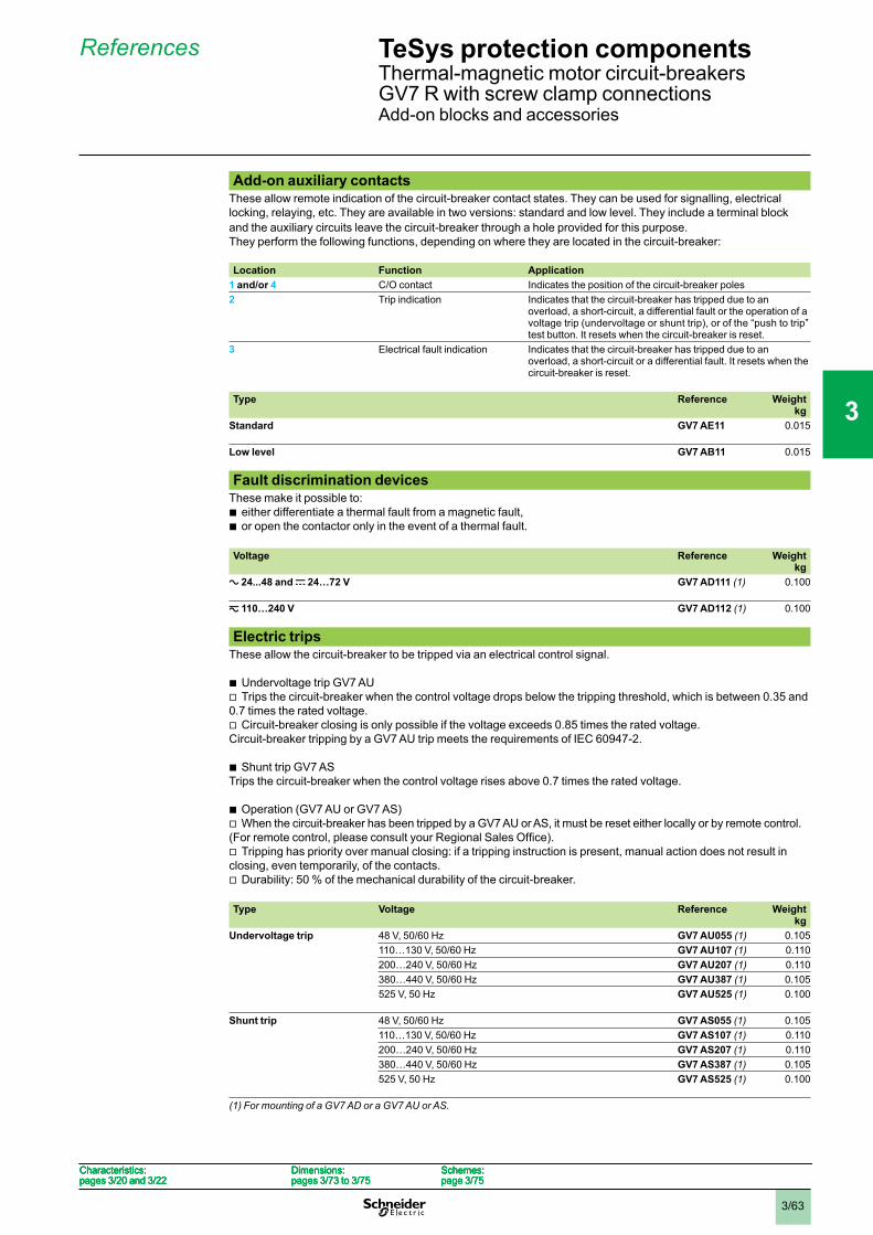
3/63
Add-on auxiliary contactsThese allow remote indication of the circuit-breaker contact states. They can be used for signalling, electricallocking, relaying, etc. They are available in two versions: standard and low level. They include a terminal blockand the auxiliary circuits leave the circuit-breaker through a hole provided for this purpose.They perform the following functions, depending on where they are located in the circuit-breaker:
Location Function Application1 and/or 4 C/O contact Indicates the position of the circuit-breaker poles2 Trip indication Indicates that the circuit-breaker has tripped due to an
overload, a short-circuit, a differential fault or the operation of avoltage trip (undervoltage or shunt trip), or of the “push to trip”test button. It resets when the circuit-breaker is reset.
3 Electrical fault indication Indicates that the circuit-breaker has tripped due to anoverload, a short-circuit or a differential fault. It resets when thecircuit-breaker is reset.
Type Reference Weightkg
Standard GV7 AE11 0.015
Low level GV7 AB11 0.015
Fault discrimination devicesThese make it possible to:
either differentiate a thermal fault from a magnetic fault,or open the contactor only in the event of a thermal fault.
bb
Voltage Reference Weightkg
a 24...48 and c 24…72 V GV7 AD111 (1) 0.100
z 110…240 V GV7 AD112 (1) 0.100
Electric tripsThese allow the circuit-breaker to be tripped via an electrical control signal.
Undervoltage trip GV7 AUTrips the circuit-breaker when the control voltage drops below the tripping threshold, which is between 0.35 and
0.7 times the rated voltage.Circuit-breaker closing is only possible if the voltage exceeds 0.85 times the rated voltage.
Circuit-breaker tripping by a GV7 AU trip meets the requirements of IEC 60947-2.
Shunt trip GV7 ASTrips the circuit-breaker when the control voltage rises above 0.7 times the rated voltage.
Operation (GV7 AU or GV7 AS)When the circuit-breaker has been tripped by a GV7 AU or AS, it must be reset either locally or by remote control.
Tripping has priority over manual closing: if a tripping instruction is present, manual action does not result inclosing, even temporarily, of the contacts.
Durability: 50 % of the mechanical durability of the circuit-breaker.
bv
v
b
bv
v
v
Type Voltage Reference Weightkg
Undervoltage trip 48 V, 50/60 Hz GV7 AU055 (1) 0.105110…130 V, 50/60 Hz GV7 AU107 (1) 0.110200…240 V, 50/60 Hz GV7 AU207 (1) 0.110380…440 V, 50/60 Hz GV7 AU387 (1) 0.105525 V, 50 Hz GV7 AU525 (1) 0.100
Shunt trip 48 V, 50/60 Hz GV7 AS055 (1) 0.105110…130 V, 50/60 Hz GV7 AS107 (1) 0.110200…240 V, 50/60 Hz GV7 AS207 (1) 0.110380…440 V, 50/60 Hz GV7 AS387 (1) 0.105525 V, 50 Hz GV7 AS525 (1) 0.100
(1) For mounting of a GV7 AD or a GV7 AU or AS.
Characteristics:pages 3/20 and 3/22
Dimensions:pages 3/73 to 3/75
Schemes:page 3/75
Characteristics:pages 3/20 and 3/22
Dimensions:pages 3/73 to 3/75
Schemes:page 3/75
Characteristics:pages 3/20 and 3/22
Dimensions:pages 3/73 to 3/75
Schemes:page 3/75
Characteristics:pages 3/20 and 3/22
Dimensions:pages 3/73 to 3/75
Schemes:page 3/75
References TeSys protection componentsThermal-magnetic motor circuit-breakersGV7 R with screw clamp connectionsAdd-on blocks and accessories
1
2
3
4
5
6
7
8
9
10
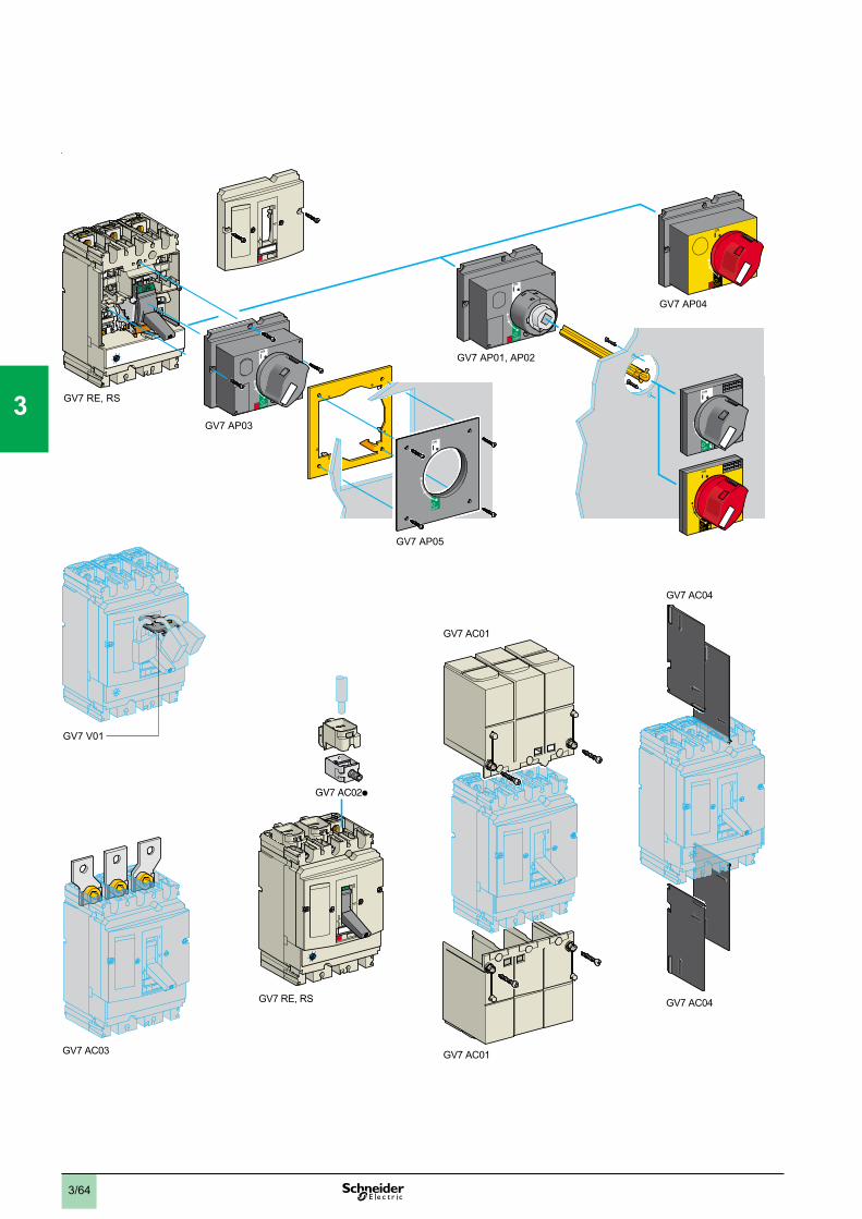
3/64
ON
OFFO
ON
OFFO
ON
OFFO
OFFO
ON
ON
OFFO
GV7 RE, RS
GV7 AP03
OFFO
ON
GV7 AP04
GV7 AP01, AP02
GV7 V01
GV7 AP05
GV7 RE, RS
GV7 AC01
GV7 AC03 GV7 AC01
GV7 AC04
GV7 AC04
1
2
3
4
5
6
7
8
9
10
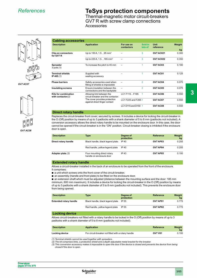
3/65
Cabling accessoriesDescription Application For use on
contactorsSold in lots of
Unitreference
Weight
kgClip-on connectors for GV7 R
Up to 150 A, 1.5…95 mm2 – 3 GV7 AC021 0.300
Up to 220 A, 1.5…185 mm2 – 3 GV7 AC022 0.350
Spreader3-pole (1)
To increase the pitch to 45 mm – 1 GV7 AC03 0.180
Terminal shields IP 405 (1)
Supplied withsealing accessory
– 1 GV7 AC01 0.125
Phase barriers Safety accessories used when – 2 GV7 AC04 0.075
Insulating screens Ensure insulation between theconnections and the backplate
– 2 GV7 AC05 0.075
Kits for combination with contactor(2)
Allowing link between thecircuit-breaker and the contactor.The cover provides protection
LC1 F115…F185 1 GV7 AC06 0.550
LC1 F225 and F265 1 GV7 AC07 0.550
LC1 D115 and D150 1 GV7 AC08 0.550
Direct rotary handleReplaces the circuit-breaker front cover; secured by screws. It includes a device for locking the circuit-breaker inthe O (Off) position by means of up to 3 padlocks with a shank diameter of 5 to 8 mm (padlocks not included). Aconversion accessory allows the direct rotary handle to be mounted on the enclosure door. In this case, the doorcannot be opened if the circuit-breaker is in the “ON” position. Circuit-breaker closing is inhibited if the enclosuredoor is open.
Description Type Degree of protection
Reference Weightkg
Direct rotary handle Black handle, black legend plate IP 40 GV7 AP03 0.205
Red handle, yellow legend plate IP 40 GV7 AP04 0.205
Adapter plate (3) Four mounting direct rotaryhandle on enclosure door
IP 43 GV7 AP05 0.100
Extended rotary handleAllows a circuit-breaker installed in the back of an enclosure to be operated from the front of the enclosure.It comprises:
a unit which screws onto the front cover of the circuit-breaker,
an extension shaft which must be adjusted (distance between the mounting surface and the door: 185 mmminimum, 600 mm maximum). It includes a device for locking the circuit-breaker in the O (Off) position by meansof up to 3 padlocks with a shank diameter of 5 to 8 mm (padlocks not included). This prevents the enclosure doorfrom being opened.
bbb
Description Type Degree of protection
Reference Weightkg
Extended rotary handle Black handle, black legend plate IP 55 GV7 AP01 0.775
Red handle, yellow legend plate IP 55 GV7 AP02 0.775
Locking device
padlocks with a shank diameter of 5 to 8 mm (padlocks not included).
Description Application Reference Weightkg
Locking device GV7 V01 0.100
(1) Terminal shields cannot be used together with spreaders.(2) The kit comprises links, a protective shield and a depth adjustable metal bracket for the breaker.(3) This conversion accessory makes it impossible to open the door if the device is closed and prevents the device from being
closed if the door is open.
+
+
GV7 AC07
+
+
GV7 AC07
+
GV7 AC08
+
GV7 AC08
Dimensions:pages 3/73 to 3/75Dimensions:pages 3/73 to 3/75Dimensions:pages 3/73 to 3/75Dimensions:pages 3/73 to 3/75
References TeSys protection componentsThermal-magnetic motor circuit-breakersGV7 R with screw clamp connectionsAccessories
1
2
3
4
5
6
7
8
9
10
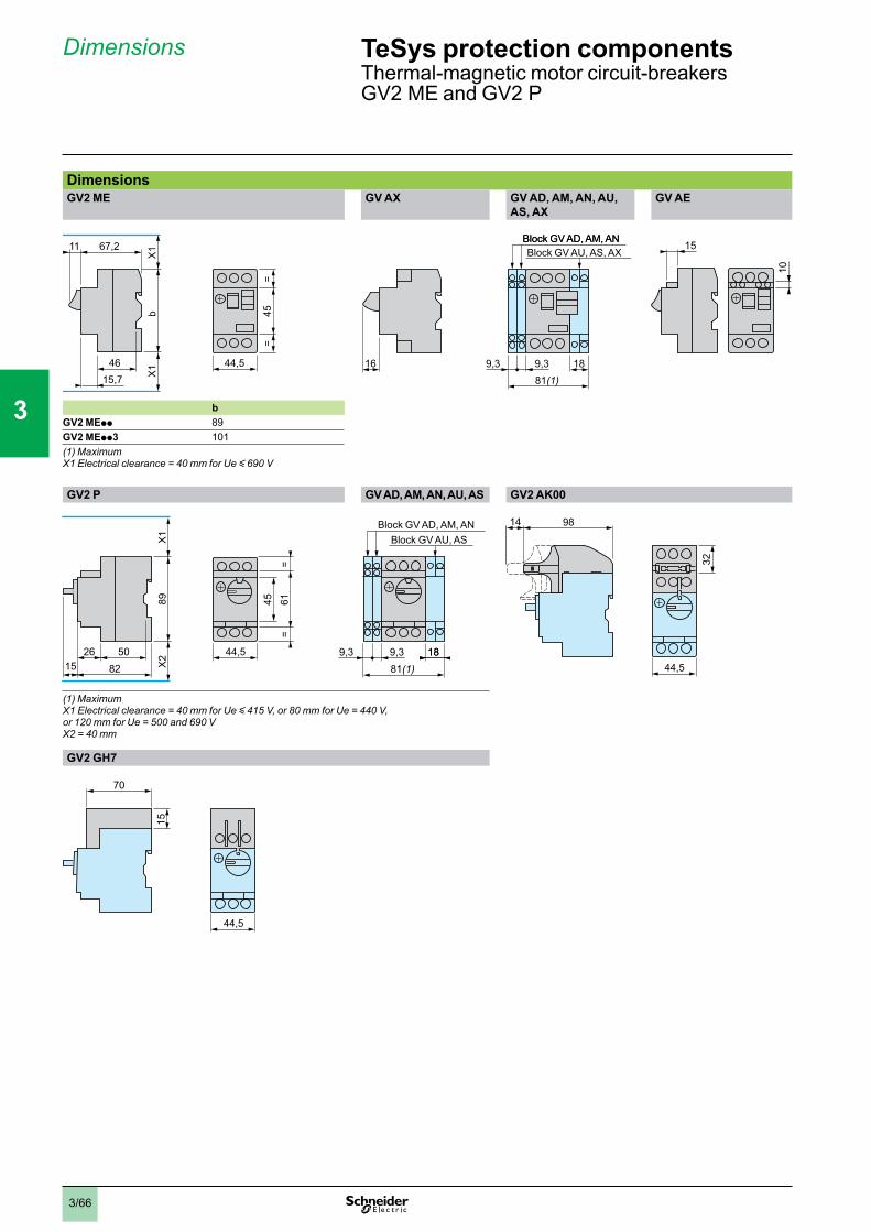
3/66
Dimensions
DimensionsGV2 ME GV AX GV AD, AM, AN, AU,
AS, AXGV AE
bGV2 MEpp 89GV2 MEpp3 101(1) MaximumX1 Electrical clearance = 40 mm for Ue y 690 V
GV2 P GV AD, AM, AN, AU, AS GV2 AK00
(1) MaximumX1 Electrical clearance = 40 mm for Ue y 415 V, or 80 mm for Ue = 440 V, or 120 mm for Ue = 500 and 690 VX2 = 40 mm
GV2 GH7
70
44,5
15b
67,2
X1
4615,7 X
1
11
45=
=
44,5
b
67,2
X1
4615,7 X
1
11
45=
=
44,5 16 9,3 9,381(1)
18
Block GV AD, AM, ANBlock GV AU, AS, AX
16 9,3 9,381(1)
18
Block GV AD, AM, ANBlock GV AU, AS, AX
15
10
15
10
44,5 9,3 9,381(1)
1818
89
82
X1
5026
X2
15
6145=
=
Block GV AD, AM, ANBlock GV AU, AS
44,5 9,3 9,381(1)
1818
89
82
X1
5026
X2
15
6145=
=
Block GV AD, AM, ANBlock GV AU, AS
9814
44,5
32
9814
44,5
32
TeSys protection componentsThermal-magnetic motor circuit-breakersGV2 ME and GV2 P
1
2
3
4
5
6
7
8
9
10
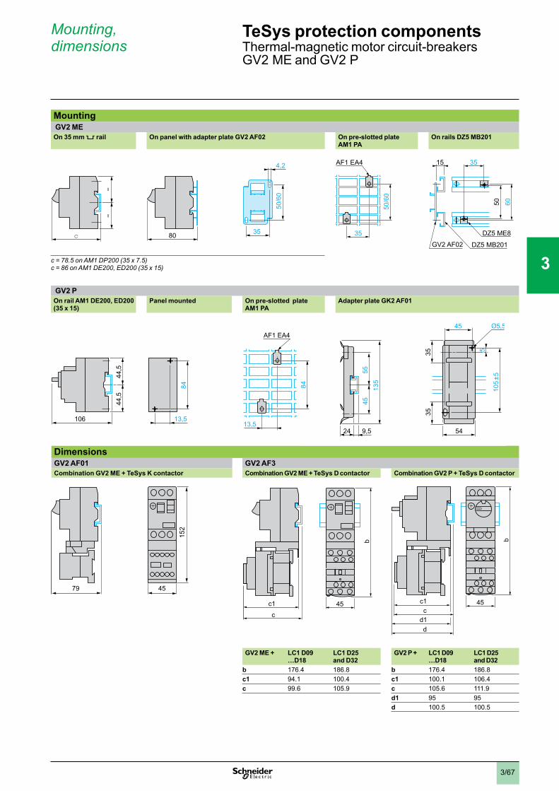
3/67
Mounting GV2 MEOn 35 mm 5 rail On panel with adapter plate GV2 AF02 On pre-slotted plate
AM1 PAOn rails DZ5 MB201
c = 78.5 on AM1 DP200 (35 x 7.5)c = 86 on AM1 DE200, ED200 (35 x 15)
GV2 POn rail AM1 DE200, ED200 (35 x 15)
Panel mounted On pre-slotted plate AM1 PA
Adapter plate GK2 AF01
DimensionsGV2 AF01 GV2 AF3Combination GV2 ME + TeSys K contactor Combination GV2 ME + TeSys D contactor Combination GV2 P + TeSys D contactor
GV2 ME + LC1 D09…D18
LC1 D25 and D32
GV2 P + LC1 D09…D18
LC1 D25 and D32
b 176.4 186.8 b 176.4 186.8c1 94.1 100.4 c1 100.1 106.4c 99.6 105.9 c 105.6 111.9
d1 95 95d 100.5 100.5
80c
==
50/6
0
4,2
3580c
==
50/6
0
4,2
35
AF1 EA4
35
50/6
0
35
6050
15
DZ5 MB201GV2 AF02
DZ5 ME8
AF1 EA4
35
50/6
0
35
6050
15
DZ5 MB201GV2 AF02
DZ5 ME8
13,5
84
44,5
44,5
106
45
3554
105
±5
35 5
AF1 EA4
84
13,524
5545
135
9,5
13,5
84
44,5
44,5
106
45
3554
105
±5
35 5
AF1 EA4
84
13,524
5545
135
9,5
79 45
152
79 45
152
c1
c45
b
c1
c45
b
45
b
c1c
dd1
45
b
c1c
dd1
TeSys protection componentsThermal-magnetic motor circuit-breakersGV2 ME and GV2 P
Mounting,dimensions
1
2
3
4
5
6
7
8
9
10
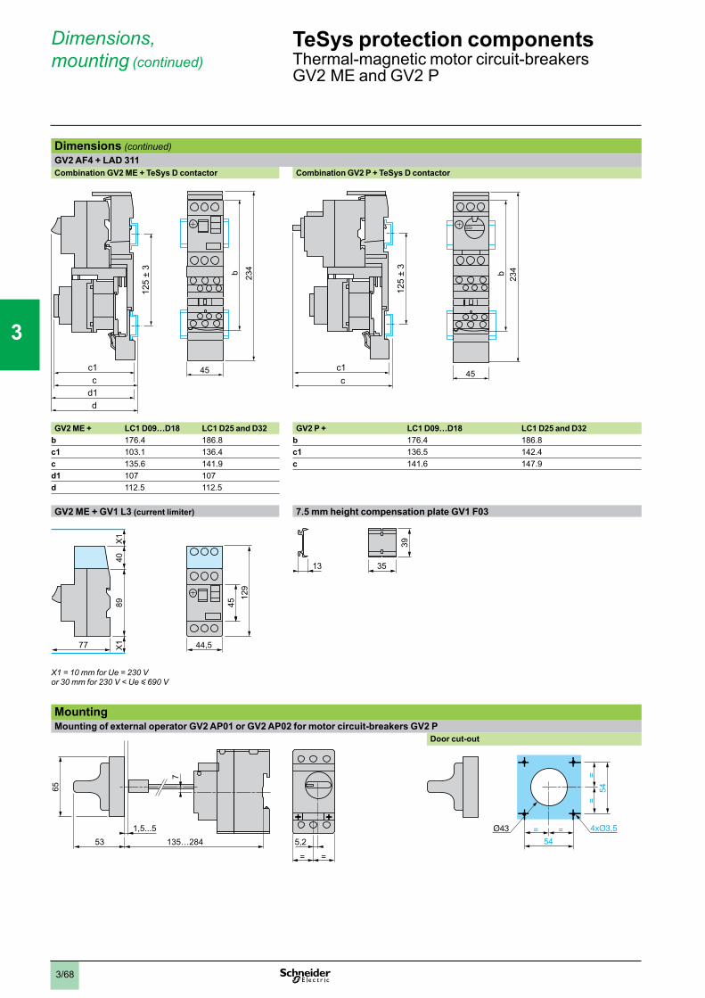
3/68
Dimensions,mounting (continued)
Dimensions (continued)GV2 AF4 + LAD 311Combination GV2 ME + TeSys D contactor Combination GV2 P + TeSys D contactor
GV2 ME + LC1 D09…D18 LC1 D25 and D32 GV2 P + LC1 D09…D18 LC1 D25 and D32b 176.4 186.8 b 176.4 186.8c1 103.1 136.4 c1 136.5 142.4c 135.6 141.9 c 141.6 147.9d1 107 107d 112.5 112.5
GV2 ME + GV1 L3 (current limiter) 7.5 mm height compensation plate GV1 F03
4512
9
44,5
89
77
X1X1
40
X1 = 10 mm for Ue = 230 V or 30 mm for 230 V < Ue y 690 V
39
3513
MountingMounting of external operator GV2 AP01 or GV2 AP02 for motor circuit-breakers GV2 P
1,5...5
7
53 135…284
65
5,2
= =
Door cut-out
=54
=
==
54
45
b 234
1
c1c
d1d
125
± 3
45
b 234
1
c1c
d1d
125
± 3
45
b 234
1
c1c
125
± 3
45
b 234
1
c1c
125
± 3
TeSys protection componentsThermal-magnetic motor circuit-breakersGV2 ME and GV2 P
1
2
3
4
5
6
7
8
9
10
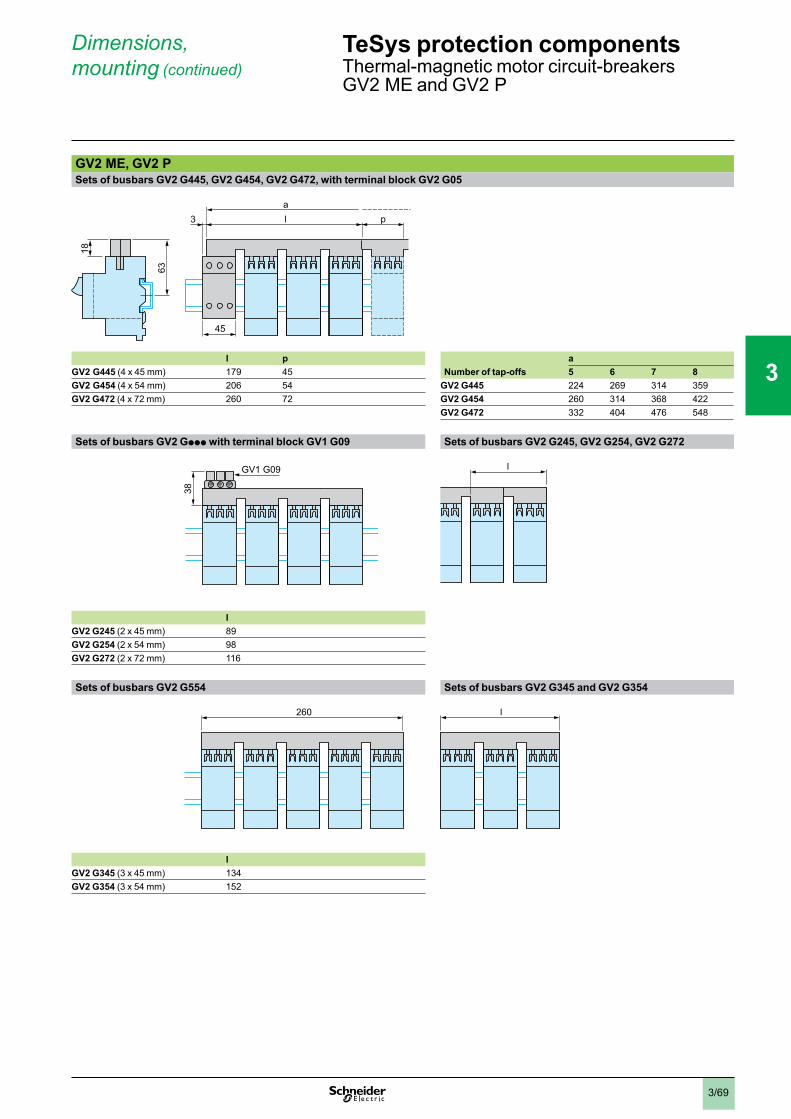
3/69
Dimensions,mounting (continued)
GV2 ME, GV2 PSets of busbars GV2 G445, GV2 G454, GV2 G472, with terminal block GV2 G05
63
l3a
18
p
45
l p aGV2 G445 (4 x 45 mm) 179 45 Number of tap-offs 5 6 7 8GV2 G454 (4 x 54 mm) 206 54 GV2 G445 224 269 314 359GV2 G472 (4 x 72 mm) 260 72 GV2 G454 260 314 368 422
GV2 G472 332 404 476 548
Sets of busbars GV2 Gppp with terminal block GV1 G09 Sets of busbars GV2 G245, GV2 G254, GV2 G272
GV1 G09
38
lGV2 G245 (2 x 45 mm) 89GV2 G254 (2 x 54 mm) 98GV2 G272 (2 x 72 mm) 116
Sets of busbars GV2 G554 Sets of busbars GV2 G345 and GV2 G354
260
lGV2 G345 (3 x 45 mm) 134GV2 G354 (3 x 54 mm) 152
ll
ll
TeSys protection componentsThermal-magnetic motor circuit-breakersGV2 ME and GV2 P
1
2
3
4
5
6
7
8
9
10
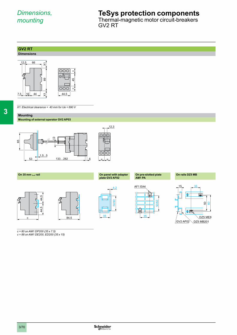
3/70
GV2 RTDimensions
X1: Electrical clearance = 40 mm for Ue < 690 V
MountingMounting of external operator GV2 AP03
1,5...5
13
53 133…282
65
6 = =
12,3
On 35 mm 7 rail On panel with adapter plate GV2 AF02
On pre-slotted plateAM1 PA
On rails DZ5 MB
c = 80 on AM1 DP200 (35 x 7.5)c = 88 on AM1 DE200, ED200 (35 x 15)
89
66
X1
44167,5 X1
12,5
45=
=
44,5
89
66
X1
44167,5 X1
12,5
45=
=
44,5
c
44,5
44,5
84,5c
44,5
44,5
84,5
50/6
0
4,2
35
50/6
0
4,2
35
AF1 EA4
35
50/6
0
AF1 EA4
35
50/6
0
35
6050
15
DZ5 MB201GV2 AF02DZ5 ME8
35
6050
15
DZ5 MB201GV2 AF02DZ5 ME8
TeSys protection componentsThermal-magnetic motor circuit-breakersGV2 RT
Dimensions,mounting
1
2
3
4
5
6
7
8
9
10
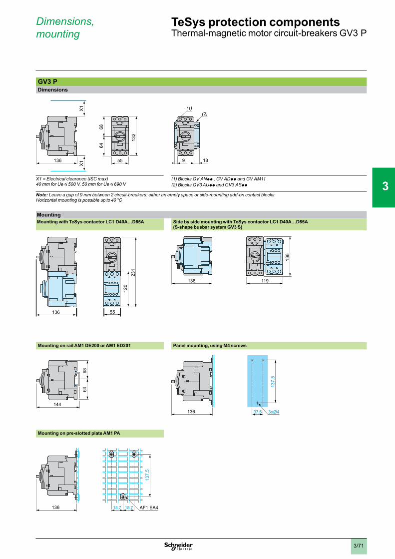
3/71
Dimensions,mounting
GV3 PDimensions
X1 = Electrical clearance (ISC max)40 mm for Ue y 500 V, 50 mm for Ue y 690 V
(1) Blocks GV ANpp , GV ADpp and GV AM11(2) Blocks GV3 AUpp and GV3 ASpp
Note: Leave a gap of 9 mm between 2 circuit-breakers: either an empty space or side-mounting add-on contact blocks.Horizontal mounting is possible up to 40 °C
MountingMounting with TeSys contactor LC1 D40A…D65A Side by side mounting with TeSys contactor LC1 D40A…D65A
(S-shape busbar system GV3 S)
231
120
136 55
136 11913
8
Mounting on rail AM1 DE200 or AM1 ED201 Panel mounting, using M4 screws
6864
144136 3xØ4
137,
5
37,5
Mounting on pre-slotted plate AM1 PA
136 18,7 18,7
137,
5
AF1 EA4
136
X1
X1
132
6864
55136
X1
X1
132
6864
55 9 18
(2)(1)
9 18
(2)(1)
TeSys protection componentsThermal-magnetic motor circuit-breakers GV3 P
1
2
3
4
5
6
7
8
9
10
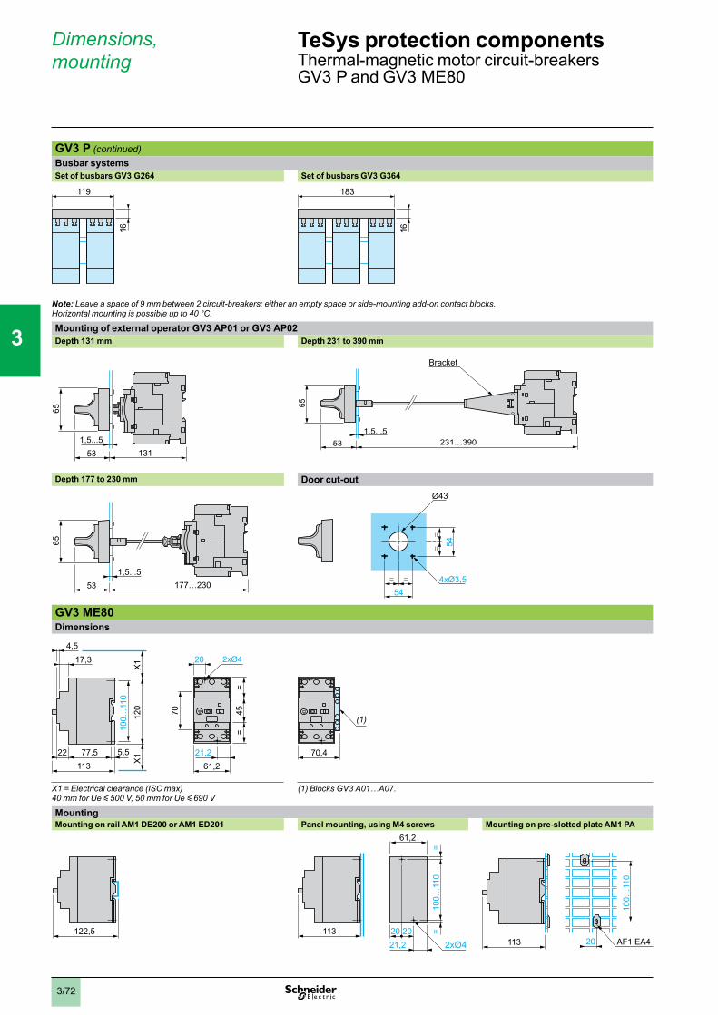
3/72
GV3 P (continued)Busbar systemsSet of busbars GV3 G264 Set of busbars GV3 G364
119
16
183
16
Note: Leave a space of 9 mm between 2 circuit-breakers: either an empty space or side-mounting add-on contact blocks. Horizontal mounting is possible up to 40 °C.
Mounting of external operator GV3 AP01 or GV3 AP02Depth 131 mm Depth 231 to 390 mm
13153
65
1,5...5 231…39053
65
1,5...5
Bracket
Depth 177 to 230 mm Door cut-out
177…23053
65
1,5...5
54= =
==
54
4xØ3,5
Ø43
GV3 ME80Dimensions
17,3
22 77,5113
100…
110
120
5,5
X1
X1
45=
=
70
61,221,2
204,5
70,4
(1)
X1 = Electrical clearance (ISC max)40 mm for Ue y 500 V, 50 mm for Ue y 690 V
(1) Blocks GV3 A01…A07.
MountingMounting on rail AM1 DE200 or AM1 ED201 Panel mounting, using M4 screws Mounting on pre-slotted plate AM1 PA
122,5 113 ==
61,2
21,22020
100…
110
20113 AF1 EA4
100…
110
Dimensions,mounting
TeSys protection componentsThermal-magnetic motor circuit-breakersGV3 P and GV3 ME80
1
2
3
4
5
6
7
8
9
10
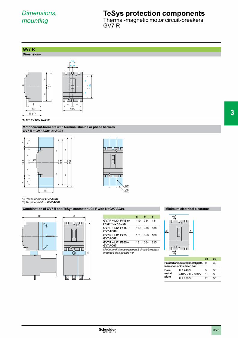
3/73
GV7 RDimensions
(1) 126 for GV7 Rp220.
Motor circuit-breakers with terminal shields or phase barriersGV7 R + GV7 AC01 or AC04
(2) Phase barriers: GV7 AC04(3) Terminal shields: GV7 AC01
Combination of GV7 R and TeSys contactor LC1 F with kit GV7 AC0p Minimum electrical clearance
a b cGV7 R + LC1 F115 or F150 + GV7 AC06
119 334 181
GV7 R + LC1 F185 + GV7 AC06
119 338 188
GV7 R + LC1 F225 + GV7 AC07
131 358 188
GV7 R + LC1 F265 + GV7 AC07
131 364 215
Minimum distance between 2 circuit-breakers mounted side by side = 0
x1 x2Painted or insulated metal plate, insulation or insulated bar
0 30
Baremetalplate
U y 440 V 5 35440 V < U < 600 V 10 35U u 600 V 20 35
8186
111 (1)
=16
1=
=
=12
5=
105
= =35
=8186
111 (1)
=16
1=
=
=12
5=
105
= =35
=
ac
b
ac
b
x1x1
x2x2
x1x1
x2x2
Dimensions,mounting
TeSys protection componentsThermal-magnetic motor circuit-breakersGV7 R
1
2
3
4
5
6
7
8
9
10
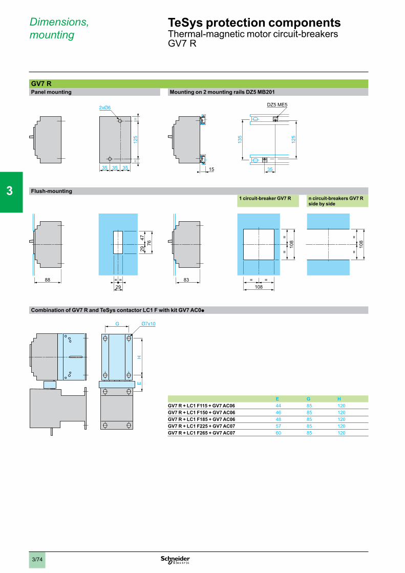
3/74
Dimensions,mounting
GV7 RPanel mounting Mounting on 2 mounting rails DZ5 MB201
Flush-mounting1 circuit-breaker GV7 R n circuit-breakers GV7 R
side by side
Combination of GV7 R and TeSys contactor LC1 F with kit GV7 AC0p
E G HGV7 R + LC1 F115 + GV7 AC06 44 85 120GV7 R + LC1 F150 + GV7 AC06 46 85 120GV7 R + LC1 F185 + GV7 AC06 48 85 120GV7 R + LC1 F225 + GV7 AC07 57 85 120GV7 R + LC1 F265 + GV7 AC07 60 85 120
35
=12
5
35 35
=
35
=12
5
35 35
=
135
35
125
DZ5 ME5
15
135
35
125
DZ5 ME5
15
=
29
=29
4776
88 83=
=10
8
= =108
==
108
=
29
=29
4776
88 83=
=10
8
= =108
==
108
G
EH
G
EH
TeSys protection componentsThermal-magnetic motor circuit-breakersGV7 R
1
2
3
4
5
6
7
8
9
10
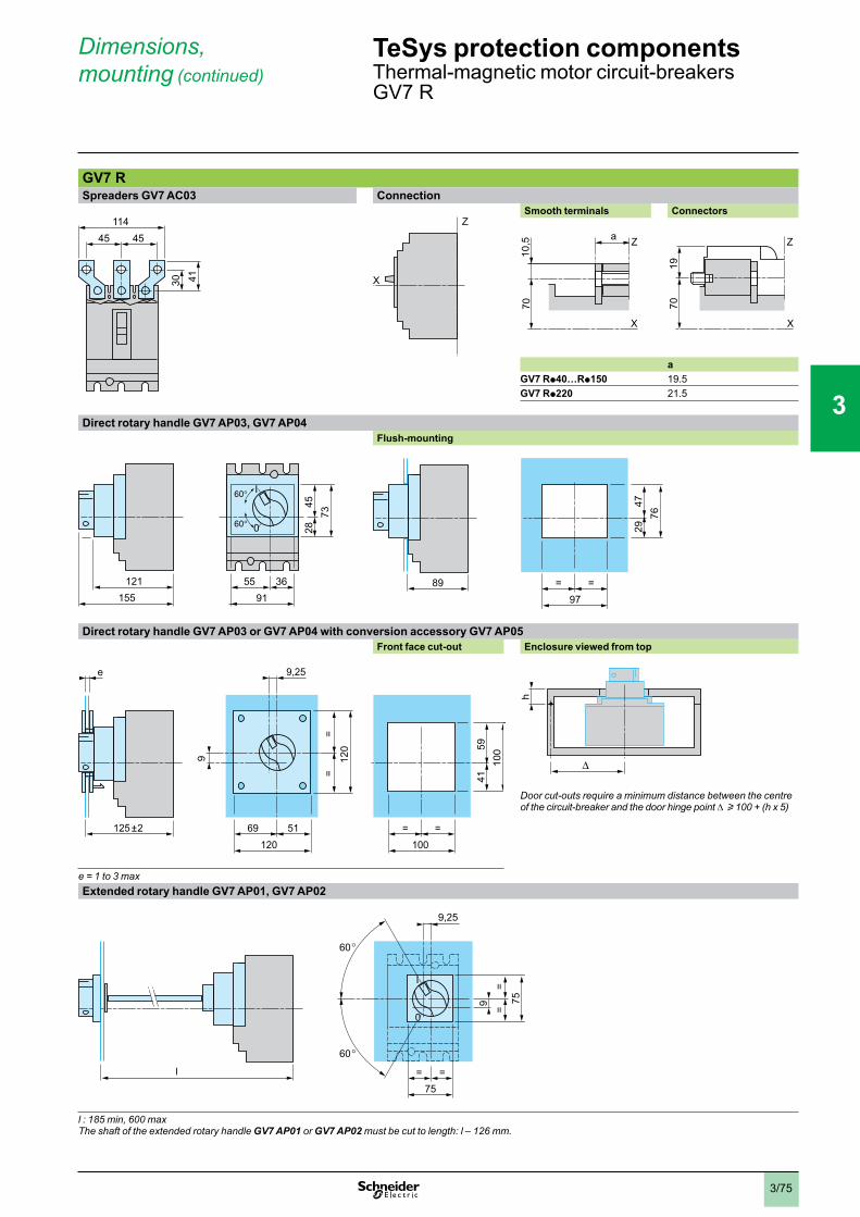
3/75
Dimensions,mounting (continued)
GV7 RSpreaders GV7 AC03 Connection Smooth terminals Connectors
aGV7 Rp40…Rp150 19.5GV7 Rp220 21.5
Direct rotary handle GV7 AP03, GV7 AP04Flush-mounting
Direct rotary handle GV7 AP03 or GV7 AP04 with conversion accessory GV7 AP05Front face cut-out Enclosure viewed from top
Door cut-outs require a minimum distance between the centre of the circuit-breaker and the door hinge point u 100 + (h x 5)
e = 1 to 3 maxExtended rotary handle GV7 AP01, GV7 AP02
l : 185 min, 600 maxThe shaft of the extended rotary handle GV7 AP01 or GV7 AP02 must be cut to length: l – 126 mm.
45 45114
30 41
45 45114
30 41
Z
X
Z
X
X
7010
,5 Z
70
Z
X
19
a
X
7010
,5 Z
70
Z
X
19
a
7345
28
155121
0
I
5591
36
7345
28
155121
0
I
5591
36 =
29
=97
4776
89 =
29
=97
4776
89
=
41
=100
5910
0
69
=
51120
=12
0
125 ±2
e
9
9,25
=
41
=100
5910
0
69
=
51120
=12
0
125 ±2
e
9
9,25
hh
75=
60
60
0
I
=
75=
=
l
9
9,25
75=
60
60
0
I
=
75=
=
l
9
9,25
TeSys protection componentsThermal-magnetic motor circuit-breakersGV7 R
1
2
3
4
5
6
7
8
9
10
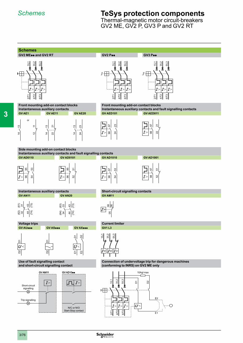
3/76
TeSys protection componentsThermal-magnetic motor circuit-breakersGV2 ME, GV2 P, GV3 P and GV2 RT
Schemes
SchemesGV2 MEpp and GV2 RT GV2 Ppp GV3 Ppp
Front mounting add-on contact blocksInstantaneous auxiliary contacts
Front mounting add-on contact blocksInstantaneous auxiliary contacts and fault signalling contacts
GV AE1 GV AE11 GV AE20 GV AED101 GV AED011
Side mounting add-on contact blocksInstantaneous auxiliary contacts and fault signalling contactsGV AD0110 GV AD0101 GV AD1010 GV AD1001
Instantaneous auxiliary contacts Short-circuit signalling contactsGV AN11 GV AN20 GV AM11
Voltage trips Current limiterGV AUppp GV ASppp GV AXppp GV1 L3
Use of fault signalling contact and short-circuit signalling contact
Connection of undervoltage trip for dangerous machines (conforming to INRS) on GV2 ME only
2/T1
4/T2
6/T3
1/L1
3/L2
5/L3
2/T1
4/T2
6/T3
1/L1
3/L2
5/L3
2/T1
4/T2
6/T3
1/L1
3/L2
5/L3
2/T1
4/T2
6/T3
1/L1
3/L2
5/L3
2/T1
4/T2
6/T3
1/L1
3/L2
5/L3
2/T1
4/T2
6/T3
1/L1
3/L2
5/L3
1314 12
11
or
1314 12
11
or
1314 22
211314 22
21 1314
2324
1314
2324
9798
2324
9798
2324
9798
2122
9798
2122
535496
95 535496
95
5251
9695
5251
9695 97
98
5354
9798
5354
9798
5152
9798
5152
(62) 32
(61) 31 43 (73)
44 (74)
(62) 32
(61) 31 43 (73)
44 (74)
(64) 34
(63) 33 43 (73)
44 (74)
(64) 34
(63) 33 43 (73)
44 (74) 05
060805
0608
D1
D2
D1
D2
D1
D2
D1
D2
D1
D2
E1 E2
D1
D2
E1 E2
1/L1
3/L2
5/L3
1/L1
3/L2
5/L3
GV AD10ppGV AM11
Short-circuitsignalling
Trip signalling
N/C or N/OStart-Stop contact
GV AD10ppGV AM11
Short-circuitsignalling
Trip signalling
N/C or N/OStart-Stop contact
2/T1
4/T2
6/T3
1/L1
3/L2
5/L3
D1
D2
E2
E1
10Agl max
2/T1
4/T2
6/T3
1/L1
3/L2
5/L3
D1
D2
E2
E1
10Agl max
1
2
3
4
5
6
7
8
9
10
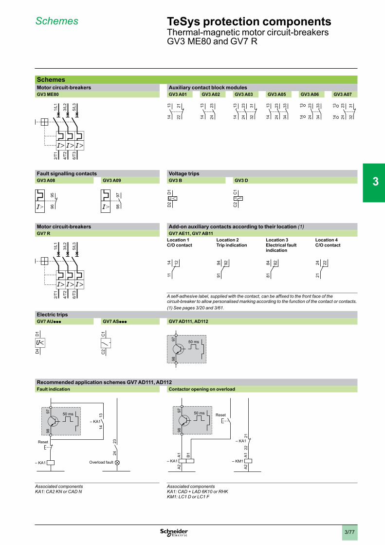
3/77
Schemes TeSys protection componentsThermal-magnetic motor circuit-breakersGV3 ME80 and GV7 R
SchemesMotor circuit-breakers Auxiliary contact block modulesGV3 ME80 GV3 A01 GV3 A02 GV3 A03 GV3 A05 GV3 A06 GV3 A07
Fault signalling contacts Voltage tripsGV3 A08 GV3 A09 GV3 B GV3 D
Motor circuit-breakers Add-on auxiliary contacts according to their location (1)GV7 R GV7 AE11, GV7 AB11 Location 1
C/O contactLocation 2Trip indication
Location 3Electrical fault indication
Location 4 C/O contact
circuit-breaker to allow personalised marking according to the function of the contact or contacts.(1) See pages 3/20 and 3/61.
Electric tripsGV7 AUppp GV7 ASppp GV7 AD111, AD112
Recommended application schemes GV7 AD111, AD112Fault indication Contactor opening on overload
Associated componentsKA1: CA2 KN or CAD N
Associated componentsKA1: CAD + LAD 6K10 or RHKKM1: LC1 D or LC1 F
2/T1
4/T2
6/T3
1/L1
3/L2
5/L3
2/T1
4/T2
6/T3
1/L1
3/L2
5/L3 13
14 222113
14 2221 13
14
2324
1314
2324
1314
2324 32
311314
2324 32
31 1314
2324
3334
1314
2324
3334
1314
2324
3334
1314
2324
3334
2324 32
311314
2324 32
311314
9695
9695 97
9897
98
D1
D2
U
D1
D2
U
C1
C2
C1
C2
2/T1
4/T2
6/T3
1/L1
3/L2
5/L3
2/T1
4/T2
6/T3
1/L1
3/L2
5/L3
1114 12
1114 12
9194 92
9194 92
8184 82
8184 82
2124 22
2124 22
D1
D4
D1
D4
C1
C2
C1
C2
9897 50 ms
9897 50 ms
9897 50 ms
– KA1
2324
1314
– KA1
Reset
Overload fault
9897 50 ms
– KA1
2324
1314
– KA1
Reset
Overload fault
9897 50 ms
– KM1– KA1
A1
A2
A1
A2
B1
– KA1
2122
Reset
9897 50 ms
– KM1– KA1
A1
A2
A1
A2
B1
– KA1
2122
Reset
1
2
3
4
5
6
7
8
9
10

3/78
Dimensions,mounting
GV2 LDimensions GV AD, AM, AN, AU, AS GV2 AK00
X1 Electrical clearance = 40 mm for Ue y 415 V, or 80 mm for Ue = 440 V, or 120 mm for Ue = 500 and 690 V.X2 = 40 mm.
(1) Maximum
Mounting Adapter plate GK2 AF01On rail AM1 DE200, AM1 ED200 (35 x 15)
Panel mounted On pre-slotted mounting plate AM1 PA
7.5 mm height compensation plate GV1 F03
GV2 LEDimensions GV AD, AM, AN, AU, AS GV AE
X1 Electrical clearance = 40 mm for Ue y 690 V. (1) MaximumMountingOn 35 mm 7 rail On panel with adapter plate GV2 AF02 On pre-slotted plate AM1 PA On rails DZ5 MB201
c = 80 on AM1 DP200(35 x 7.5) and 88 on AM1 DE200, ED200 (35 x15)
44,5 9,3 9,381 (1)
1818
89
82
X1
5026
X2
15
6145=
=
Block GV AD, AM, ANBlock GV AU, AS
44,5 9,3 9,381 (1)
1818
89
82
X1
5026
X2
15
6145=
=
Block GV AD, AM, ANBlock GV AU, AS
9814
44,5
32
9814
44,5
32
13,5
84
44,5
44,5
106
45
35
54
105±
5
35
Ø5,5
5
AF1 EA4
84
13,5 24
5545
135
9,513,5
84
44,5
44,5
106
45
35
54
105±
5
35
Ø5,5
5
AF1 EA4
84
13,5 24
5545
135
9,5
39
3513
39
3513
44
89
167,56612,5
X1
X1 44,5
45=
=
44
89
167,56612,5
X1
X1 44,5
45=
=
9,3 9,3 1881 (1)
Block GV AD, AM, ANBlock GV AU, AS
9,3 9,3 1881 (1)
Block GV AD, AM, ANBlock GV AU, AS 15
10
15
10
c
44,5
44,5
c
44,5
44,5
84,54,235
50/6
0
84,54,235
50/6
0
AF1 EA4
35
50/6
0
AF1 EA4
35
50/6
0
15 35
50 60
DZ5 MB201GV2 AF02DZ5 ME8
15 35
50 60
DZ5 MB201GV2 AF02DZ5 ME8
TeSys protection componentsMagnetic motor circuit-breakersGV2 L and GV2 LE
1
2
3
4
5
6
7
8
9
10
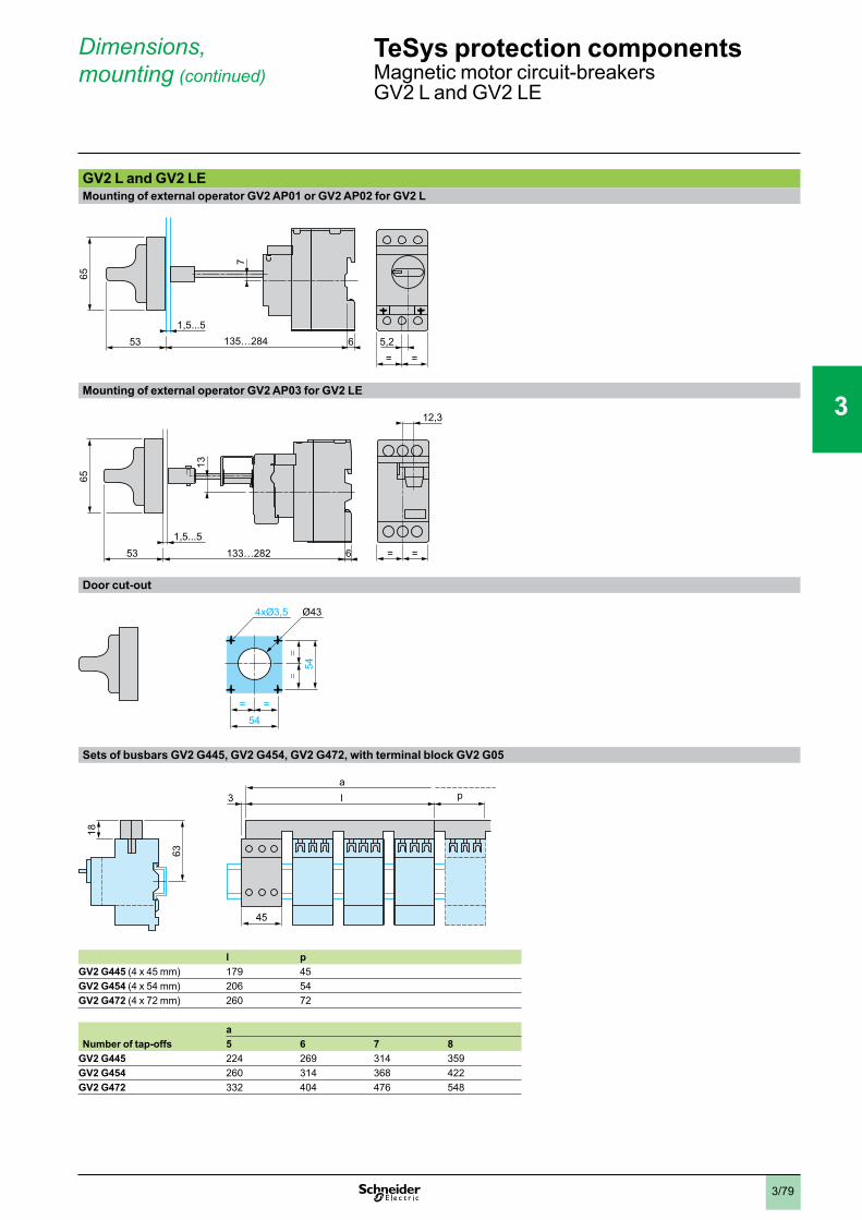
3/79
Dimensions,mounting (continued)
GV2 L and GV2 LEMounting of external operator GV2 AP01 or GV2 AP02 for GV2 L
Mounting of external operator GV2 AP03 for GV2 LE
Door cut-out
Sets of busbars GV2 G445, GV2 G454, GV2 G472, with terminal block GV2 G05
l pGV2 G445 (4 x 45 mm) 179 45GV2 G454 (4 x 54 mm) 206 54GV2 G472 (4 x 72 mm) 260 72
aNumber of tap-offs 5 6 7 8
GV2 G445 224 269 314 359GV2 G454 260 314 368 422GV2 G472 332 404 476 548
5,2= =
1,5...5
7
53 6135…284
65
5,2= =
1,5...5
7
53 6135…284
65
1,5...5
13
53 133…282
65
6 = =
12,3
1,5...5
13
53 133…282
65
6 = =
12,3
54= =
==
54
4xØ3,5 Ø43
54= =
==
54
4xØ3,5 Ø43
63
l3a
18
p
45
63
l3a
18
p
45
TeSys protection components0
Magnetic motor circuit-breakersGV2 L and GV2 LE
1
2
3
4
5
6
7
8
9
10
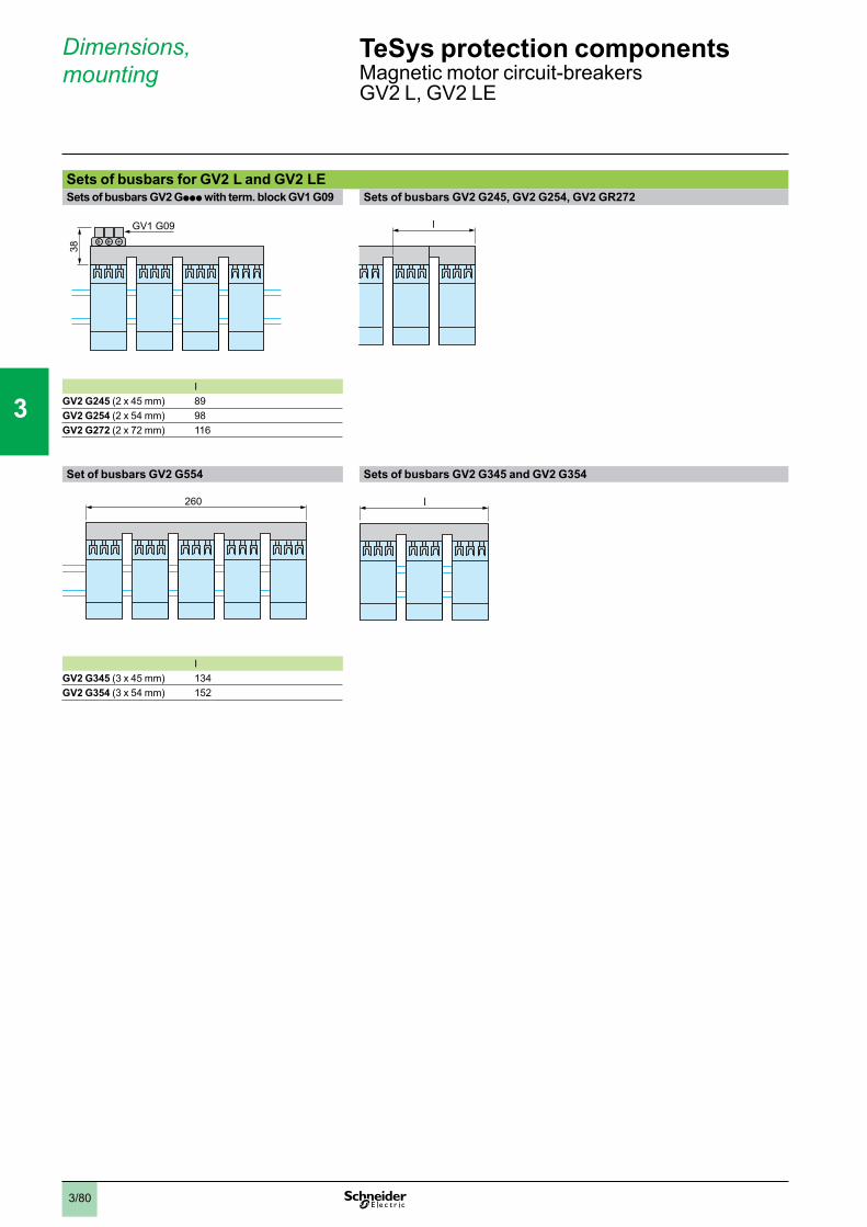
3/80
Dimensions,mounting
Sets of busbars for GV2 L and GV2 LESets of busbars GV2 Gppp with term. block GV1 G09 Sets of busbars GV2 G245, GV2 G254, GV2 GR272
IGV2 G245 (2 x 45 mm) 89GV2 G254 (2 x 54 mm) 98GV2 G272 (2 x 72 mm) 116
Set of busbars GV2 G554 Sets of busbars GV2 G345 and GV2 G354
IGV2 G345 (3 x 45 mm) 134GV2 G354 (3 x 54 mm) 152
ll
260260 ll
TeSys protection componentsMagnetic motor circuit-breakersGV2 L, GV2 LE
GV1 G09
38
1
2
3
4
5
6
7
8
9
10
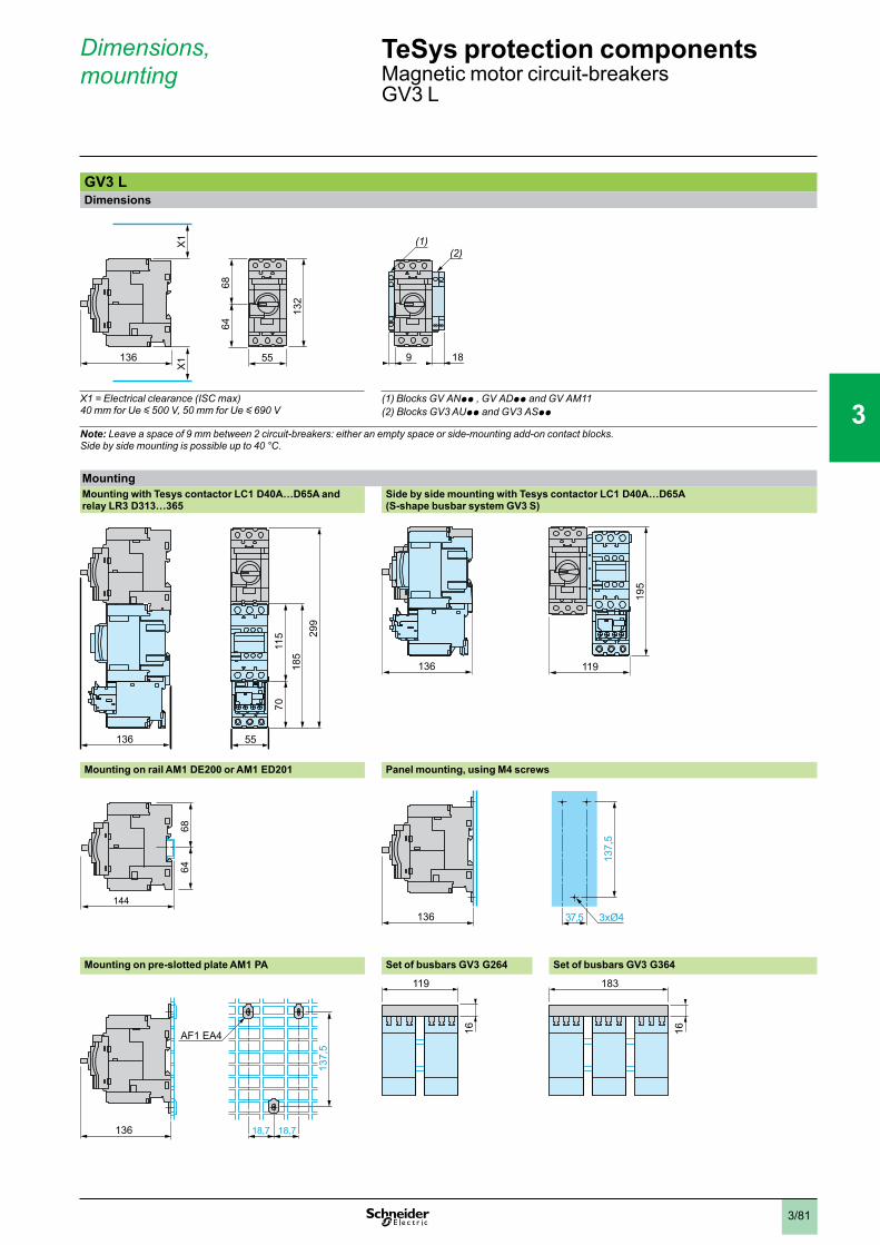
3/81
GV3 LDimensions
X1 = Electrical clearance (ISC max) 40 mm for Ue y 500 V, 50 mm for Ue y 690 V
(1) Blocks GV ANpp , GV ADpp and GV AM11(2) Blocks GV3 AUpp and GV3 ASpp
Note: Leave a space of 9 mm between 2 circuit-breakers: either an empty space or side-mounting add-on contact blocks.Side by side mounting is possible up to 40 °C.
MountingMounting with Tesys contactor LC1 D40A…D65A and relay LR3 D313…365
Side by side mounting with Tesys contactor LC1 D40A…D65A(S-shape busbar system GV3 S)
185
299
7011
5
136 55
136 119
195
Mounting on rail AM1 DE200 or AM1 ED201 Panel mounting, using M4 screws
144
6864
136 3xØ4
137,
5
37,5
Mounting on pre-slotted plate AM1 PA Set of busbars GV3 G264 Set of busbars GV3 G364
136 18,7 18,7
137,
5
AF1 EA4
119
16
183
16
136
X1
X1
132
6864
55136
X1
X1
132
6864
55 9 18
(2)(1)
9 18
(2)(1)
Dimensions,mounting
TeSys protection componentsMagnetic motor circuit-breakersGV3 L
1
2
3
4
5
6
7
8
9
10
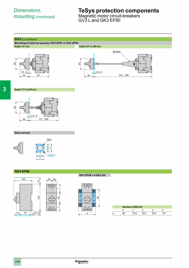
3/82
Dimensions,mounting (continued)
TeSys protection componentsMagnetic motor circuit-breakersGV3 L and GK3 EF80
GV3 L (continued)Mounting of external operator GV3 AP01 or GV3 AP02Depth 131 mm Depth 231 to 390 mm
13153
65
1,5...5231…39053
65
1,5...5
Bracket
Depth 177 to 230 mm
177…23053
65
1,5...5
Door cut-out
54= =
==
54
4xØ3,5
Ø43
GK3 EF80GK3 EF80 + 4 GK2 AX
70 4,515
120
X1
X1
105 38 28
45=
=
a
80
Number of GK2 AX0 1 2 3 4
a 66 74.8 83.5 92.5 101
1
2
3
4
5
6
7
8
9
10
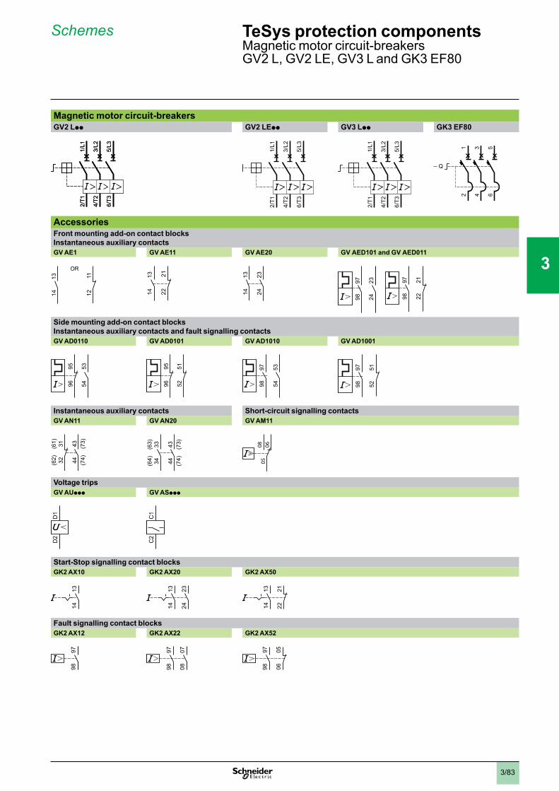
3/83
Schemes TeSys protection components0
Magnetic motor circuit-breakersGV2 L, GV2 LE, GV3 L and GK3 EF80
Magnetic motor circuit-breakersGV2 Lpp GV2 LEpp GV3 Lpp GK3 EF80
AccessoriesFront mounting add-on contact blocksInstantaneous auxiliary contactsGV AE1 GV AE11 GV AE20 GV AED101 and GV AED011
Side mounting add-on contact blocksInstantaneous auxiliary contacts and fault signalling contactsGV AD0110 GV AD0101 GV AD1010 GV AD1001
Instantaneous auxiliary contacts Short-circuit signalling contactsGV AN11 GV AN20 GV AM11
Voltage tripsGV AUppp GV ASppp
Start-Stop signalling contact blocksGK2 AX10 GK2 AX20 GK2 AX50
Fault signalling contact blocksGK2 AX12 GK2 AX22 GK2 AX52
2/T1
4/T2
6/T3
1/L1
3/L2
5/L3
2/T1
4/T2
6/T3
1/L1
3/L2
5/L3
2/T1
4/T2
6/T3
1/L1
3/L2
5/L3
2/T1
4/T2
6/T3
1/L1
3/L2
5/L3
2/T1
4/T2
6/T3
1/L1
3/L2
5/L3
2/T1
4/T2
6/T3
1/L1
3/L2
5/L3
1314 12
11
OR
1314 12
11
OR
1314 22
211314 22
21 1314
2324
1314
2324
9798
2324
9798
2122
9798
2324
9798
2122
535496
95 535496
95
5251
9695
5251
9695 97
98
5354
9798
5354
9798
5152
9798
5152
(62) 32
(61) 31 43 (73)
44 (74)
(62) 32
(61) 31 43 (73)
44 (74)
(64) 34
(63) 33 43 (73)
44 (74)
(64) 34
(63) 33 43 (73)
44 (74) 05
060805
0608
D1
D2
D1
D2
C1
C2
C1
C2
1314
1314
1314
2324
1314
2324 22
211314 22
211314
9798
9798
9798
0708
9798
0708
9798 06
059798 06
05
1
2
3
4
5
6
7
8
9
10
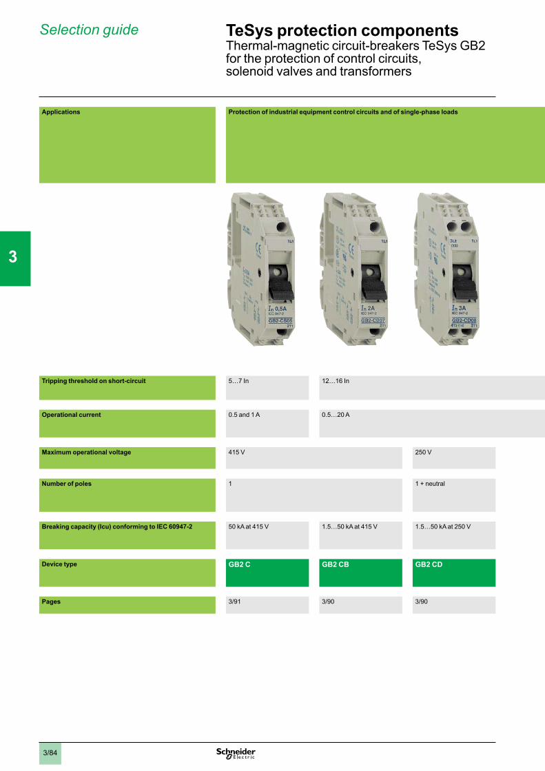
3/84
Applications Protection of industrial equipment control circuits and of single-phase loads
Tripping threshold on short-circuit 5…7 In 12…16 In
Operational current 0.5 and 1 A 0.5…20 A
Maximum operational voltage 415 V 250 V
Number of poles 1 1 + neutral
Breaking capacity (Icu) conforming to IEC 60947-2 50 kA at 415 V 1.5…50 kA at 415 V 1.5…50 kA at 250 V
Device type GB2 C GB2 CB GB2 CD
Pages 3/91 3/90 3/90
TeSys protection componentsThermal-magnetic circuit-breakers TeSys GB2for the protection of control circuits,solenoid valves and transformers
Selection guide
1
2
3
4
5
6
7
8
9
10
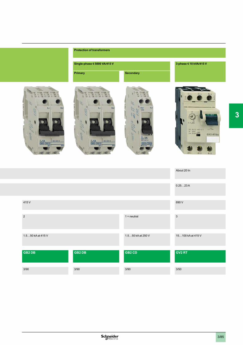
3/85
Protection of transformers
Single-phase y 5000 VA/415 V 3-phase y 10 kVA/415 V
Primary Secondary
About 20 In
0.25…23 A
415 V 690 V
2 1 + neutral 3
1.5…50 kA at 415 V 1.5…50 kA at 250 V 15…100 kA at 415 V
GB2 DB GB2 DB GB2 CD GV2 RT
3/90 3/90 3/90 3/50
1
2
3
4
5
6
7
8
9
10
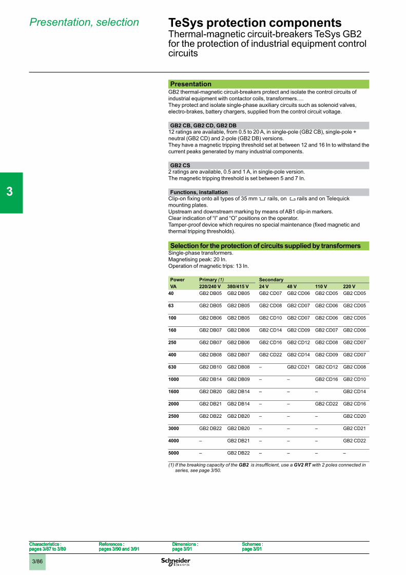
3/86
PresentationGB2 thermal-magnetic circuit-breakers protect and isolate the control circuits ofindustrial equipment with contactor coils, transformers.…They protect and isolate single-phase auxiliary circuits such as solenoid valves,electro-brakes, battery chargers, supplied from the control circuit voltage. GB2 CB, GB2 CD, GB2 DB
12 ratings are available, from 0.5 to 20 A, in single-pole (GB2 CB), single-pole +neutral (GB2 CD) and 2-pole (GB2 DB) versions.They have a magnetic tripping threshold set at between 12 and 16 In to withstand thecurrent peaks generated by many industrial components. GB2 CS
2 ratings are available, 0.5 and 1 A, in single-pole version.The magnetic tripping threshold is set between 5 and 7 In. Functions, installation
5 rails, on 4 rails and on Telequickmounting plates.Upstream and downstream marking by means of AB1 clip-in markers.Clear indication of “I” and “O” positions on the operator.
thermal tripping thresholds). Selection for the protection of circuits supplied by transformers
Single-phase transformers.Magnetising peak: 20 In.Operation of magnetic trips: 13 In. Power Primary (1) SecondaryVA 220/240 V 380/415 V 24 V 48 V 110 V 220 V
40 GB2 DB05 GB2 DB05 GB2 CD07 GB2 CD06 GB2 CD05 GB2 CD05
63 GB2 DB05 GB2 DB05 GB2 CD08 GB2 CD07 GB2 CD06 GB2 CD05
100 GB2 DB06 GB2 DB05 GB2 CD10 GB2 CD07 GB2 CD06 GB2 CD05
160 GB2 DB07 GB2 DB06 GB2 CD14 GB2 CD09 GB2 CD07 GB2 CD06
250 GB2 DB07 GB2 DB06 GB2 CD16 GB2 CD12 GB2 CD08 GB2 CD07
400 GB2 DB08 GB2 DB07 GB2 CD22 GB2 CD14 GB2 CD09 GB2 CD07
630 GB2 DB10 GB2 DB08 – GB2 CD21 GB2 CD12 GB2 CD08
1000 GB2 DB14 GB2 DB09 – – GB2 CD16 GB2 CD10
1600 GB2 DB20 GB2 DB14 – – – GB2 CD14
2000 GB2 DB21 GB2 DB14 – – GB2 CD22 GB2 CD16
2500 GB2 DB22 GB2 DB20 – – – GB2 CD20
3000 GB2 DB22 GB2 DB20 – – – GB2 CD21
4000 – GB2 DB21 – – – GB2 CD22
5000 – GB2 DB22 – – – –
(1) If the breaking capacity of the GB2 GV2 RT with 2 poles connected in series, see page 3/50.
Characteristics :pages 3/87 to 3/89
References :pages 3/90 and 3/91
Dimensions :page 3/91
Schemes :page 3/91
Characteristics :pages 3/87 to 3/89
References :pages 3/90 and 3/91
Dimensions :page 3/91
Schemes :page 3/91
Characteristics :pages 3/87 to 3/89
References :pages 3/90 and 3/91
Dimensions :page 3/91
Schemes :page 3/91
Characteristics :pages 3/87 to 3/89
References :pages 3/90 and 3/91
Dimensions :page 3/91
Schemes :page 3/91
TeSys protection componentsThermal-magnetic circuit-breakers TeSys GB2for the protection of industrial equipment controlcircuits
Presentation, selection
1
2
3
4
5
6
7
8
9
10
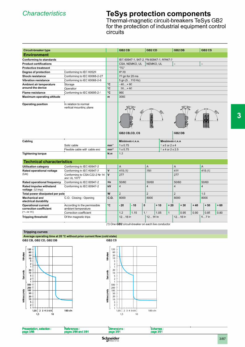
3/87
Circuit-breaker type GB2 CB GB2 CD GB2 DB GB2 CS
EnvironmentConforming to standards IEC 60947-1, 947-2, EN 60947-1, 60947-2
CSA, NEMKO, UL NEMKO, UL – –Protective treatment “TC”Degree of protection Conforming to IEC 60529 IP 20Shock resistance Conforming to IEC 60068-2-27 22 gn for 20 msVibration resistance Conforming to IEC 60068-2-6 5 gn (5…110 Hz)Ambient air temperature around the device
Storage °C - 40…+ 80Operation °C - 20…+ 60
Flame resistance Conforming to IEC 60695-2-1 °C 960Maximum operating altitude m 3000
Operating position In relation to normalvertical mounting plane
GB2 CB,CD, CS GB2 DB
Cabling Minimum c.s.a. Maximum c.s.a.Solid cable mm2 1 x 0.75 1 x 6 or 2 x 4Flexible cable with cable end mm2 1 x 0.75 1 x 4 or 2 x 2.5
Tightening torque N.m 1.2
Technical characteristicsUtilisation category Conforming to IEC 60947-2 A A A ARated operational voltage (Ue)
Conforming to IEC 60947-2 V 415 (1) 250 415 415 (1)Conforming to CSA C22-2 Nr 14and UL 1077
V 277 – 277 –
Rated operational frequency Conforming to IEC 60947-2 Hz 50/60 50/60 50/60 50/60Rated impulse withstand voltage (U imp)
Conforming to IEC 60947-2 kV 4 4 4 4
Total power dissipated per pole W 2 2 2 1.9Mechanical andelectrical durability
C.O.: Closing - Opening C.O. 8000 8000 8000 8000
Operational current
(a or c)
According to the permissibleambient temperature
°C - 20 - 10 0 + 10 + 20 + 30 + 40 + 50 + 60
1.2 1.15 1.1 1.05 1 0.95 0.90 0.85 0.80Tripping threshold Of the magnetic trips 12…16 In 12…16 In 12…16 In 5…7 In
(1) One GB2 circuit-breaker on each live conductor.2
Tripping curves
GB2 CB, GB2 CD, GB2 DB GB2 CS
1,051,5
2 3 4 5 6 810
1
52
2010
10050
1
52
2010
1
52
2010
60120
500200
100 x In1,051,5
2 3 4 5 6 810
1
52
2010
10050
1
52
2010
1
52
2010
60120
500200
100 x In1,051,5
2 3 4 5 6 810
1
52
2010
10050
1
52
2010
1
52
2010
60120
500200
100 x In1,051,5
2 3 4 5 6 810
1
52
2010
10050
1
52
2010
1
52
2010
60120
500200
100 x In
Mill
isec
onds
Mill
isec
onds
Sec
onds
Sec
onds
Min
utes
Min
utes
1,051,5
2 3 4 5 6 810
1
52
2010
10050
1
52
2010
1
52
2010
60120
500200
100 x In1,051,5
2 3 4 5 6 810
1
52
2010
10050
1
52
2010
1
52
2010
60120
500200
100 x In
Mill
isec
onds
Mill
isec
onds
Sec
onds
Sec
onds
Min
utes
Min
utes
Presentation, selection :page 3/86
References :pages 3/90 and 3/91
Dimensions :page 3/91
Schemes :page 3/91
Presentation, selection :page 3/86
References :pages 3/90 and 3/91
Dimensions :page 3/91
Schemes :page 3/91
Presentation, selection :page 3/86
References :pages 3/90 and 3/91
Dimensions :page 3/91
Schemes :page 3/91
Presentation, selection :page 3/86
References :pages 3/90 and 3/91
Dimensions :page 3/91
Schemes :page 3/91
TeSys protection componentsThermal-magnetic circuit-breakers TeSys GB2for the protection of industrial equipment controlcircuits
Characteristics
1
2
3
4
5
6
7
8
9
10
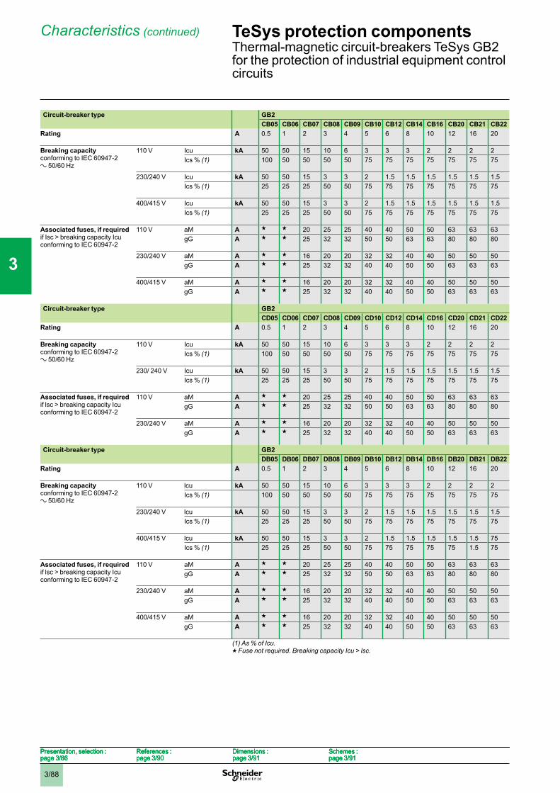
3/88
Circuit-breaker type GB2CB05 CB06 CB07 CB08 CB09 CB10 CB12 CB14 CB16 CB20 CB21 CB22
Rating A 0.5 1 2 3 4 5 6 8 10 12 16 20
Breaking capacityconforming to IEC 60947-2a 50/60 Hz
110 V Icu kA 50 50 15 10 6 3 3 3 2 2 2 2Ics % (1) 100 50 50 50 50 75 75 75 75 75 75 75
230/240 V Icu kA 50 50 15 3 3 2 1.5 1.5 1.5 1.5 1.5 1.5Ics % (1) 25 25 25 50 50 75 75 75 75 75 75 75
400/415 V Icu kA 50 50 15 3 3 2 1.5 1.5 1.5 1.5 1.5 1.5Ics % (1) 25 25 25 50 50 75 75 75 75 75 75 75
Associated fuses, if requiredif Isc > breaking capacity Icuconforming to IEC 60947-2
110 V aM A g g 20 25 25 40 40 50 50 63 63 63gG A g g 25 32 32 50 50 63 63 80 80 80
230/240 V aM A g g 16 20 20 32 32 40 40 50 50 50gG A g g 25 32 32 40 40 50 50 63 63 63
400/415 V aM A g g 16 20 20 32 32 40 40 50 50 50gG A g g 25 32 32 40 40 50 50 63 63 63
Circuit-breaker type GB2CD05 CD06 CD07 CD08 CD09 CD10 CD12 CD14 CD16 CD20 CD21 CD22
Rating A 0.5 1 2 3 4 5 6 8 10 12 16 20
Breaking capacityconforming to IEC 60947-2a 50/60 Hz
110 V Icu kA 50 50 15 10 6 3 3 3 2 2 2 2Ics % (1) 100 50 50 50 50 75 75 75 75 75 75 75
230/ 240 V Icu kA 50 50 15 3 3 2 1.5 1.5 1.5 1.5 1.5 1.5Ics % (1) 25 25 25 50 50 75 75 75 75 75 75 75
Associated fuses, if requiredif lsc > breaking capacity Icuconforming to IEC 60947-2
110 V aM A g g 20 25 25 40 40 50 50 63 63 63gG A g g 25 32 32 50 50 63 63 80 80 80
230/240 V aM A g g 16 20 20 32 32 40 40 50 50 50gG A g g 25 32 32 40 40 50 50 63 63 63
Circuit-breaker type GB2DB05 DB06 DB07 DB08 DB09 DB10 DB12 DB14 DB16 DB20 DB21 DB22
Rating A 0.5 1 2 3 4 5 6 8 10 12 16 20
Breaking capacityconforming to IEC 60947-2a 50/60 Hz
110 V lcu kA 50 50 15 10 6 3 3 3 2 2 2 2Ics % (1) 100 50 50 50 50 75 75 75 75 75 75 75
230/240 V lcu kA 50 50 15 3 3 2 1.5 1.5 1.5 1.5 1.5 1.5Ics % (1) 25 25 25 50 50 75 75 75 75 75 75 75
400/415 V lcu kA 50 50 15 3 3 2 1.5 1.5 1.5 1.5 1.5 75Ics % (1) 25 25 25 50 50 75 75 75 75 75 1.5 75
Associated fuses, if requiredif lsc > breaking capacity Icuconforming to IEC 60947-2
110 V aM A g g 20 25 25 40 40 50 50 63 63 63gG A g g 25 32 32 50 50 63 63 80 80 80
230/240 V aM A g g 16 20 20 32 32 40 40 50 50 50gG A g g 25 32 32 40 40 50 50 63 63 63
400/415 V aM A g g 16 20 20 32 32 40 40 50 50 50gG A g g 25 32 32 40 40 50 50 63 63 63
(1) As % of Icu.g Fuse not required. Breaking capacity Icu > lsc.
Presentation, selection :page 3/86
References :page 3/90
Dimensions :page 3/91
Schemes :page 3/91
Presentation, selection :page 3/86
References :page 3/90
Dimensions :page 3/91
Schemes :page 3/91
Presentation, selection :page 3/86
References :page 3/90
Dimensions :page 3/91
Schemes :page 3/91
Presentation, selection :page 3/86
References :page 3/90
Dimensions :page 3/91
Schemes :page 3/91
TeSys protection componentsThermal-magnetic circuit-breakers TeSys GB2for the protection of industrial equipment controlcircuits
Characteristics (continued)
1
2
3
4
5
6
7
8
9
10
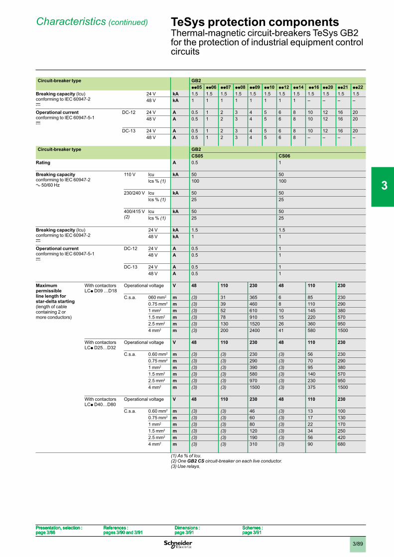
3/89
Circuit-breaker type GB2pp05 pp06 pp07 pp08 pp09 pp10 pp12 pp14 pp16 pp20 pp21 pp22
Breaking capacity (lcu)conforming to IEC 60947-2c
24 V kA 1.5 1.5 1.5 1.5 1.5 1.5 1.5 1.5 1.5 1.5 1.5 1.548 V kA 1 1 1 1 1 1 1 1 – – – –
Operational currentconforming to IEC 60947-5-1c
DC-12 24 V A 0.5 1 2 3 4 5 6 8 10 12 16 2048 V A 0.5 1 2 3 4 5 6 8 10 12 16 20
DC-13 24 V A 0.5 1 2 3 4 5 6 8 10 12 16 2048 V A 0.5 1 2 3 4 5 6 8 – – – –
Circuit-breaker type GB2CS05 CS06
Rating A 0.5 1
Breaking capacityconforming to IEC 60947-2a 50/60 Hz
110 V lcu kA 50 50lcs % (1) 100 100
230/240 V lcu kA 50 50lcs % (1) 25 25
400/415 V(2)
lcu kA 50 50lcs % (1) 25 25
Breaking capacity (lcu) conforming to IEC 60947-2c
24 V kA 1.5 1.548 V kA 1 1
Operational currentconforming to IEC 60947-5-1c
DC-12 24 V A 0.5 148 V A 0.5 1
DC-13 24 V A 0.5 148 V A 0.5 1
Maximumpermissibleline length for star-delta starting (length of cablecontaining 2 ormore conductors)
With contactorsLCp D09 …D18
Operational voltage V 48 110 230 48 110 230
C.s.a. 060 mm2 m (3) 31 365 6 85 2300.75 mm2 m (3) 39 460 8 110 2901 mm2 m (3) 52 610 10 145 3801.5 mm2 m (3) 78 910 15 220 5702.5 mm2 m (3) 130 1520 26 360 9504 mm2 m (3) 200 2400 41 580 1500
With contactorsLCp D25…D32
Operational voltage V 48 110 230 48 110 230
C.s.a. 0.60 mm2 m (3) (3) 230 (3) 56 2300.75 mm2 m (3) (3) 290 (3) 70 2901 mm2 m (3) (3) 390 (3) 95 3801.5 mm2 m (3) (3) 580 (3) 140 5702.5 mm2 m (3) (3) 970 (3) 230 9504 mm2 m (3) (3) 1500 (3) 375 1500
With contactorsLCp D40…D80
Operational voltage V 48 110 230 48 110 230
C.s.a. 0.60 mm2 m (3) (3) 46 (3) 13 1000.75 mm2 m (3) (3) 60 (3) 17 1301 mm2 m (3) (3) 80 (3) 22 1701.5 mm2 m (3) (3) 120 (3) 34 2502.5 mm2 m (3) (3) 190 (3) 56 4204 mm2 m (3) (3) 310 (3) 90 680
(1) As % of Icu.(2) One GB2 CS circuit-breaker on each live conductor.(3) Use relays.
Presentation, selection :page 3/86
References :pages 3/90 and 3/91
Dimensions :page 3/91
Schemes :page 3/91
Presentation, selection :page 3/86
References :pages 3/90 and 3/91
Dimensions :page 3/91
Schemes :page 3/91
Presentation, selection :page 3/86
References :pages 3/90 and 3/91
Dimensions :page 3/91
Schemes :page 3/91
Presentation, selection :page 3/86
References :pages 3/90 and 3/91
Dimensions :page 3/91
Schemes :page 3/91
TeSys protection componentsThermal-magnetic circuit-breakers TeSys GB2for the protection of industrial equipment controlcircuits
Characteristics (continued)
1
2
3
4
5
6
7
8
9
10
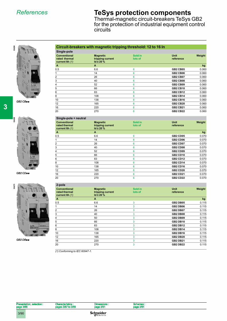
3/90
Circuit-breakers with magnetic tripping threshold: 12 to 16 InSingle-poleConventionalrated thermal current Ith (1)
Magnetictripping currentId ± 20 %
Sold in lots of
Unitreference
Weight
A A kg0.5 6.6 6 GB2 CB05 0.0601 14 6 GB2 CB06 0.0602 26 6 GB2 CB07 0.0603 40 6 GB2 CB08 0.0604 52 6 GB2 CB09 0.0605 66 6 GB2 CB10 0.0606 83 6 GB2 CB12 0.0608 108 6 GB2 CB14 0.06010 138 6 GB2 CB16 0.06012 165 6 GB2 CB20 0.06016 220 6 GB2 CB21 0.06020 270 6 GB2 CB22 0.060
Single-pole + neutralConventionalrated thermal current Ith (1)
Magnetictripping current Id ± 20 %
Sold in lots of
Unitreference
Weight
A A kg0.5 6.6 6 GB2 CD05 0.0701 14 6 GB2 CD06 0.0702 26 6 GB2 CD07 0.0703 40 6 GB2 CD08 0.0704 52 6 GB2 CD09 0.0705 66 6 GB2 CD10 0.0706 83 6 GB2 CD12 0.0708 108 6 GB2 CD14 0.07010 138 6 GB2 CD16 0.07012 165 6 GB2 CD20 0.07016 220 6 GB2 CD21 0.07020 270 6 GB2 CD22 0.070
2-poleConventionalrated thermal current Ith (1)
Magnetictripping currentId ± 20 %
Sold in lots of
Unitreference
Weight
A A kg0.5 6.6 3 GB2 DB05 0.1151 14 3 GB2 DB06 0.1152 26 3 GB2 DB07 0.1153 40 3 GB2 DB08 0.1154 50 3 GB2 DB09 0.1155 66 3 GB2 DB10 0.1156 83 3 GB2 DB12 0.1158 108 3 GB2 DB14 0.11510 138 3 GB2 DB16 0.11512 165 3 GB2 DB20 0.11516 220 3 GB2 DB21 0.11520 270 3 GB2 DB22 0.115
(1) Conforming to IEC 60947-1.
5342
68
GB2 CBpp
5342
68
GB2 CBpp
5342
69
GB2 CDpp
5342
69
GB2 CDpp
5342
70
GB2 DBpp
5342
70
GB2 DBpp
Presentation, selection :page 3/86
Characteristics :pages 3/87 to 3/89
Dimensions :page 3/91
Schemes :page 3/91
Presentation, selection :page 3/86
Characteristics :pages 3/87 to 3/89
Dimensions :page 3/91
Schemes :page 3/91
Presentation, selection :page 3/86
Characteristics :pages 3/87 to 3/89
Dimensions :page 3/91
Schemes :page 3/91
Presentation, selection :page 3/86
Characteristics :pages 3/87 to 3/89
Dimensions :page 3/91
Schemes :page 3/91
TeSys protection componentsThermal-magnetic circuit-breakers TeSys GB2for the protection of industrial equipment controlcircuits
References
1
2
3
4
5
6
7
8
9
10
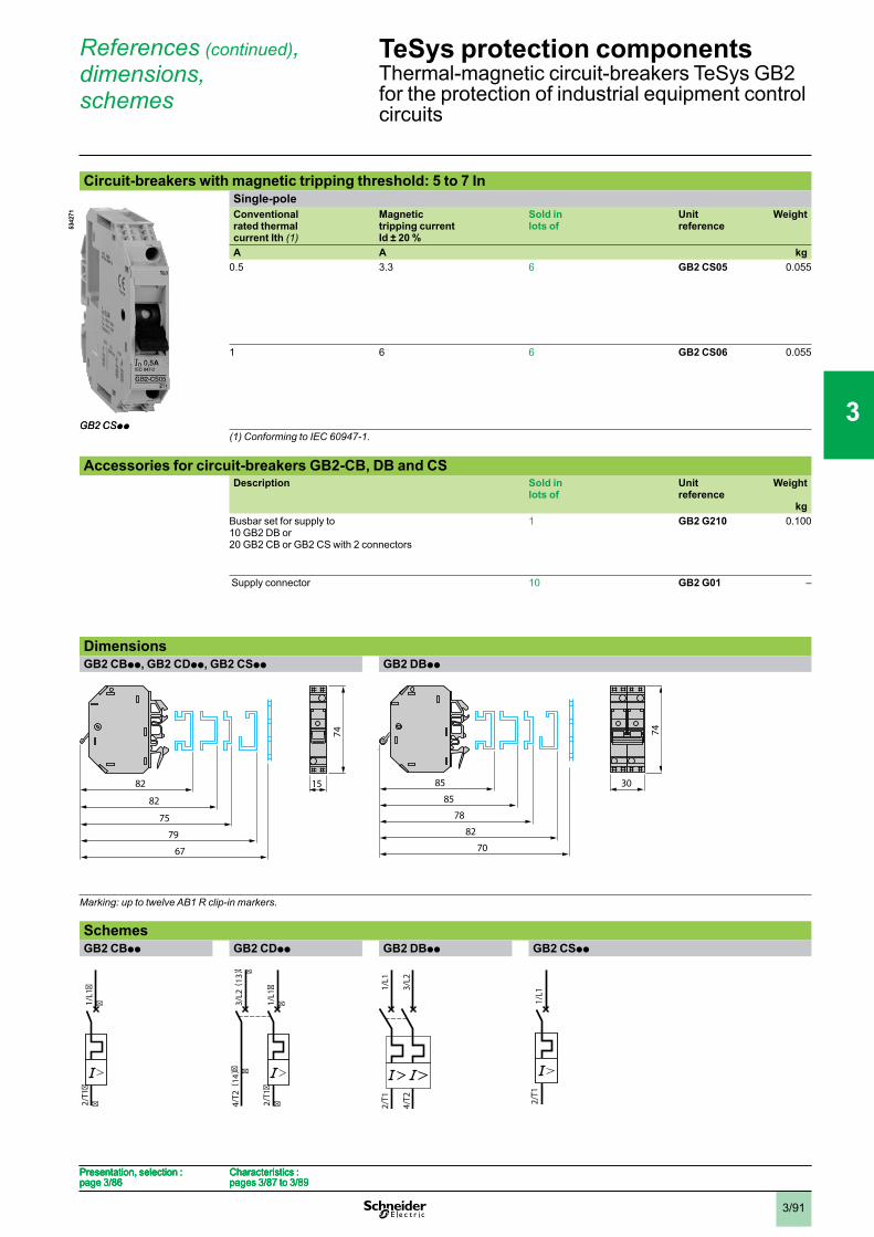
3/91
Circuit-breakers with magnetic tripping threshold: 5 to 7 InSingle-poleConventionalrated thermal current Ith (1)
Magnetictripping currentId ± 20 %
Sold in lots of
Unitreference
Weight
A A kg0.5 3.3 6 GB2 CS05 0.055
1 6 6 GB2 CS06 0.055
(1) Conforming to IEC 60947-1.
Accessories for circuit-breakers GB2-CB, DB and CSDescription Sold in
lots ofUnitreference
Weight
kgBusbar set for supply to10 GB2 DB or20 GB2 CB or GB2 CS with 2 connectors
1 GB2 G210 0.100
Supply connector 10 GB2 G01 –
DimensionsGB2 CBpp, GB2 CDpp, GB2 CSpp GB2 DBpp
Marking: up to twelve AB1 R clip-in markers.
SchemesGB2 CBpp GB2 CDpp GB2 DBpp GB2 CSpp
5342
71
GB2 CSpp
5342
71
GB2 CSpp
74
1582
82
75
79
67
74
1582
82
75
79
67
30
74
85
85
78
82
70
30
74
85
85
78
82
70
2/T1
��
1/L1
��
2/T1
��
1/L1
��
2/T1
��
1/L1
��3/
L2( 1
3)� �
4/T
2 ( 1
4)� �
2/T1
��
1/L1
��3/
L2( 1
3)� �
4/T
2 ( 1
4)� �
1/L1
3/L2
2/T1
4/T2
1/L1
3/L2
2/T1
4/T2 2/
T11/
L12/
T11/
L1
Presentation, selection :page 3/86
Characteristics :pages 3/87 to 3/89
Presentation, selection :page 3/86
Characteristics :pages 3/87 to 3/89
Presentation, selection :page 3/86
Characteristics :pages 3/87 to 3/89
Presentation, selection :page 3/86
Characteristics :pages 3/87 to 3/89
TeSys protection componentsThermal-magnetic circuit-breakers TeSys GB2for the protection of industrial equipment controlcircuits
References (continued),dimensions,schemes
1
2
3
4
5
6
7
8
9
10
Related Documents