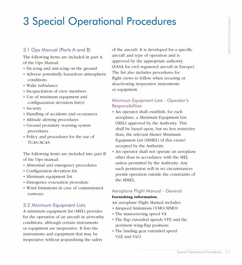
Special Operational Procedures 3-1 OPERATIONAL PROCEDURES 3.1 Ops Manual (Parts A and B) The following items are included in part A of the Ops Manual: • De-icing and anti-icing on the ground • Adverse potentially hazardous atmospheric conditions • Wake turbulance • Incapacitation of crew members • Use of minimum equipment and configuaration deviation list(s) • Security • Handling of accidents and occurances • Altitude alerting procedures • Ground proximity warning system procedures • Policy and procedures for the use of TCAS/ACAS. The following items are included into part B of the Ops manual: • Abnormal and emergency procedures • Configuration deviation list • Minimum equipment list • Emergence evacuation procedure • Wind limitations in case of contaminated runways. 3.2 Minimum Equipment Lists A minimum equipment list (MEL) provides for the operation of an aircraft in airworthy conditions, although certain instruments or equipment are inoperative. It lists the instruments and equipment that may be inoperative without jeopardising the safety of the aircraft. It is developed for a specific aircraft and type of operation and is approved by the appropriate authority (EASA for civil registered aircraft in Europe). The list also includes procedures for flight crews to follow when securing or deactivating inoperative instruments or equipment. Minimum Equipment Lists - Operator’s Responsibilities • An operator shall establish, for each aeroplane, a Minimum Equipment List (MEL) approved by the Authority. This shall be based upon, but no less restrictive than, the relevant Master Minimum Equipment List (MMEL) (i f this exists) accepted by the Authority. • An operator shall not operate an aeroplane other than in accordance with the MEL unless permitted by the Authority. Any such permission will in no circumstances permit operation outside the constraints of the MMEL. Aeroplane Flight Manual - General Furnishing information. An aeroplane Flight Manual includes: • Airspeed limitations (VMO/MMO) • The manoeuvring speed VA • The flap extended speeds VFE and the pertinent wing-flap positions • The landing gear extended speed VLE and VLO 3 Special Operational Procedures

Welcome message from author
This document is posted to help you gain knowledge. Please leave a comment to let me know what you think about it! Share it to your friends and learn new things together.
Transcript
Special Operational Procedures 3-1
OPER
ATION
AL PRO
CED
URES
3.1 Ops Manual (Parts A and B)The following items are included in part A of the Ops Manual:• De-icing and anti-icing on the ground• Adverse potentially hazardous atmospheric
conditions• Wake turbulance• Incapacitation of crew members• Use of minimum equipment and
configuaration deviation list(s)• Security• Handling of accidents and occurances• Altitude alerting procedures• Ground proximity warning system
procedures• Policy and procedures for the use of
TCAS/ACAS.
The following items are included into part B of the Ops manual:• Abnormal and emergency procedures• Configuration deviation list• Minimum equipment list• Emergence evacuation procedure• Wind limitations in case of contaminated
runways.
3.2 Minimum Equipment ListsA minimum equipment list (MEL) provides for the operation of an aircraft in airworthy conditions, although certain instruments or equipment are inoperative. It lists the instruments and equipment that may be inoperative without jeopardising the safety
of the aircraft. It is developed for a specific aircraft and type of operation and is approved by the appropriate authority (EASA for civil registered aircraft in Europe).The list also includes procedures for flight crews to follow when securing or deactivating inoperative instruments or equipment.
Minimum Equipment Lists - Operator’s Responsibilities• An operator shall establish, for each
aeroplane, a Minimum Equipment List (MEL) approved by the Authority. This shall be based upon, but no less restrictive than, the relevant Master Minimum Equipment List (MMEL) (if this exists) accepted by the Authority.
• An operator shall not operate an aeroplane other than in accordance with the MEL unless permitted by the Authority. Any such permission will in no circumstances permit operation outside the constraints of the MMEL.
Aeroplane Flight Manual - GeneralFurnishing information.
An aeroplane Flight Manual includes:• Airspeed limitations (VMO/MMO)• The manoeuvring speed VA• The flap extended speeds VFE and the
pertinent wing-flap positions• The landing gear extended speed
VLE and VLO
3 Special Operational Procedures
3-2 Special Operational Procedures
OPER
ATION
AL PRO
CED
URES
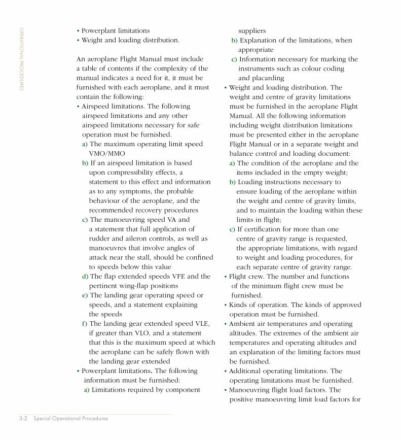
• Powerplant limitations• Weight and loading distribution.
An aeroplane Flight Manual must include a table of contents if the complexity of the manual indicates a need for it, it must be furnished with each aeroplane, and it must contain the following:• Airspeed limitations. The following
airspeed limitations and any other airspeed limitations necessary for safe operation must be furnished.
a) The maximum operating limit speed VMO/MMO
b) If an airspeed limitation is based upon compressibility effects, a statement to this effect and information as to any symptoms, the probable behaviour of the aeroplane, and the recommended recovery procedures
c) The manoeuvring speed VA and a statement that full application of rudder and aileron controls, as well as manoeuvres that involve angles of attack near the stall, should be confined to speeds below this value
d) The flap extended speeds VFE and the pertinent wing-flap positions
e) The landing gear operating speed or speeds, and a statement explaining the speeds
f) The landing gear extended speed VLE, if greater than VLO, and a statement that this is the maximum speed at which the aeroplane can be safely flown with the landing gear extended
• Powerplant limitations. The following information must be furnished:
a) Limitations required by component
suppliers b) Explanation of the limitations, when
appropriate c) Information necessary for marking the
instruments such as colour coding and placarding
• Weight and loading distribution. The weight and centre of gravity limitations must be furnished in the aeroplane Flight Manual. All the following information including weight distribution limitations must be presented either in the aeroplane Flight Manual or in a separate weight and balance control and loading document:
a) The condition of the aeroplane and the items included in the empty weight;
b) Loading instructions necessary to ensure loading of the aeroplane within the weight and centre of gravity limits, and to maintain the loading within these limits in flight;
c) If certification for more than one centre of gravity range is requested, the appropriate limitations, with regard to weight and loading procedures, for each separate centre of gravity range.
• Flight crew. The number and functions of the minimum flight crew must be furnished.
• Kinds of operation. The kinds of approved operation must be furnished.
• Ambient air temperatures and operating altitudes. The extremes of the ambient air temperatures and operating altitudes and an explanation of the limiting factors must be furnished.
• Additional operating limitations. The operating limitations must be furnished.
• Manoeuvring flight load factors. The positive manoeuvring limit load factors for
Special Operational Procedures 3-3
OPER
ATION
AL PRO
CED
URES
which the structure is proven, described in terms of accelerations, must be furnished.
• Systems and equipment limitations must be furnished.
• A limitation on the maximum depth of runway contaminants for take-off operation must be furnished.
• Other information that is necessary for safe operation because of design, operating, or handling characteristics.
• Emergency procedures which are concerned with foreseeable but unusual situations in which immediate and precise action by the crew, as detailed in the recommended procedures, may be expected substantially to reduce the risk of catastrophe.
• Malfunctions. Other procedures peculiar to the particular type or model en-countered in connection with routine operations including malfunction cases and failure conditions, involving the use of special systems and/or the alternative use of regular systems not considered as emergency procedures.
• The buffet onset envelopes must be furnished. The buffet onset envelopes presented may reflect the centre of gravity at which the aeroplane is normally loaded during cruise if corrections for the effect of different centre of gravity locations are furnished.
• Zero fuel indication. Information must be furnished which indicates that when the fuel quantity indicator reads ‘zero’ in level flight, any fuel remaining in the fuel tank cannot be used safely in flight.
• Information on the total quantity of usable fuel for each fuel tank must be furnished.
Performance information computed under the applicable provisions of this JAR-25 for the weights, altitudes, temperatures, wind components, and runway gradients, as applicable, within the operational limits of the aeroplane. It must contain the condition of power, configuration, speeds and the procedures for handling the aeroplane and any system having a significant effect on performance upon which the performance graphs are based must be stated in each case.
The following gross performance information (determined by extrapolation and computed for the range of weights between the maximum landing weight and maximum take-off weight) must be provided:• Climb in the landing configuration• Climb in the approach configuration• Landing distance• Procedures related to limitations and
information required by this paragraph must be stated in the form of guidance material including any relevant limitation or information
• An explanation of significant or unusual flight or ground handling characteristics of the aeroplane
• Corrections to indicated values of airspeed, altitude and outside air temperature.
• An explanation of operational landing runway length factors included in the presentation of the landing distance, if appropriate
• Any limitation, procedure, or other information established as a condition of compliance with the National Noise Regulations.

3-4 Special Operational Procedures
OPER
ATION
AL PRO
CED
URES
3.3 Aeroplane De-Icing and Anti-IcingAircraft can experience icing conditions and effects both on the ground and in the air. Ice will form on the airframe if:• There is liquid water;• Ambient temperature below 0°C; and/or• Airframe temperature below 0°C.
Icing can affect the aerodynamic surfaces, flying controls, powerplant and aircraft performance - both aerodynamically and by the penalty due to the extra weight of ice adhering to the airframe. It is necessary to remove any ice accumulated on the airframe before flight or, if icing conditions are encountered in flight, as soon as possible after icing effects are experienced.
Take-off is prohibited when frost, ice or snow is adhering to any critical surface of the aircraft. This is referred to as “The Clean Aircraft Concept”. The Clean Aircraft Concept is essential to the maintenance of flight safety.
Dangers of Aircraft Icing• Increase in weight;• Loss of lift, deformation of aerodynamic
characteristics. Icing creates aerodynamic penalties because of its irregular shape and rough surface, which disrupts the flow of air passing over the airfoils. For a given speed and angle of attack, wing lift can be reduced by as much as 30 percent and drag increased by up to 40 percent;
• The stall speed of an ice covered aircraft may be 20 to 30 percent higher than normal;
• Loss of power, carburettor icing;
• Loss of control, icing on control surface hinges;
• Loss of thrust, propeller icing;• Loss of vision, windscreen freezing;•. Loss of communication, icing of aerials;• Pitot tube icing;• Unbalance of aircraft, unbalance of
propellers,• Ice on critical surfaces and on the airframe
may also break away during take-off and be ingested into engines, possibly damaging fan and compressor blades.
It is necessary to remove any ice accumulated on the airframe before flight or, if icing conditions are encountered in flight, as soon as possible after icing effects are experienced.
Before detailing the requirements for operations in icing conditions it is important to clarify the terminology that will be used.
De-icing. De-icing refers to the removal of ice that has already formed.
Anti-icing. Anti-icing is the treatment employed, or the use of equipment to prevent the initial formation of ice.
Airframe icing. Airframe icing is the accumulation of ice on the airframe and control surfaces.
Engine icing. Engine icing refers to the build up of ice in the vicinity of the engines that will have the effect of reducing or disrupting the flow of air through the engine leading to a reduction in engine performance. The type of engine icing depends on the type of
Special Operational Procedures 3-5
OPER
ATION
AL PRO
CED
URES
powerplant as, for example, piston engines aircraft can suffer from carburettor icing whereas turbine powered aircraft can suffer compressor surge and/or stall as a result of ice forming on the engine intake lip.
Holdover Time. Is the estimated time for which an anti-icing fluid will prevent the formation of frost or ice and the accumulation of snow on the protected surfaces of an aircraft, under specified weather conditions.
Ice and Other Contaminants • An operator shall establish procedures to
be followed when ground de-icing and anti-icing and related inspections of the aeroplane(s) are necessary.
• A commander shall not commence take-off unless the external surfaces are clear of any deposit which might adversely affect the performance and/or controllability of the aeroplane except as permitted in the Aeroplane Flight Manual.
• A commander shall not commence a flight under known or expected icing conditions unless the aeroplane is certificated and equipped to cope with such conditions.
Ice and other Contaminants - Flight Procedures • An operator shall establish procedures
for flights in expected or actual icing conditions.
• A commander shall not commence a flight nor intentionally fly into expected or actual icing conditions unless the aeroplane is certificated and equipped to cope with such conditions.
Equipment for Operations in Icing Conditions • An operator shall not operate an aeroplane
in expected or actual icing conditions unless it is certificated and equipped to operate in icing conditions.
• An operator shall not operate an aeroplane in expected or actual icing conditions at night unless it is equipped with a means to illuminate or detect the formation of ice. Any illumination that is used must be of a type that will not cause glare or reflection that would handicap crew members in the performance of their duties. In any event, all ice must be removed from the airframe prior to flight.
Ground De-icing of AircraftDe-icing of aircraft prior to flight can be carried out using several methods:• De-icing fluids either by spray application
or by “taxiing through”;• Warming of the airframe by hot air
blowers;• Manually sweeping the surfaces where
frost and light ice have accumulated.
De-icing and anti-icing on the ground can be carried out as either a one-step (de-icing only) or two-step (de-icing and anti-icing) process, and fluids can be applied either cold or hot. Knowledge of the prevailing weather condition, OAT and the type of contaminant must be available in order to provide appropriate protection. In the event that the aeroplane does not depart within the holdover time treatment must be repeated as required.
3-6 Special Operational Procedures
OPER
ATION
AL PRO
CED
URES
For aerodynamic reasons, the deicing and anti-icing procedures are conducted in a symmetrical fashion.
CommunicationIt is important that flight crew have an accurate picture of what de-icing/anti-icing measures have been taken by ground crew prior to their arrival at the aeroplane. In order to achieve this an Anti-icing code is used to enable the flight crew to assess the holdover time. The code must contain:• Type of fluid used;• Percentage of fluid to water (dilution);• Local time that application commenced.
All procedures for operations in icing conditions are specified in the Operations Manual.
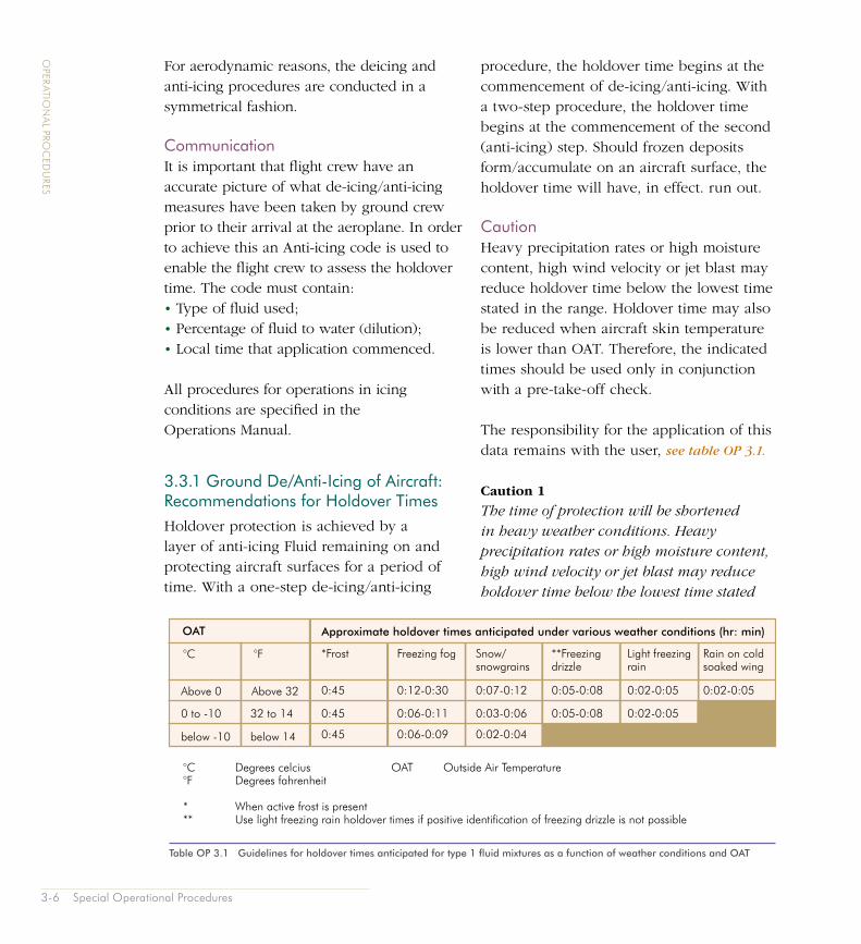
3.3.1 Ground De/Anti-Icing of Aircraft: Recommendations for Holdover TimesHoldover protection is achieved by a layer of anti-icing Fluid remaining on and protecting aircraft surfaces for a period of time. With a one-step de-icing/anti-icing
procedure, the holdover time begins at the commencement of de-icing/anti-icing. With a two-step procedure, the holdover time begins at the commencement of the second (anti-icing) step. Should frozen deposits form/accumulate on an aircraft surface, the holdover time will have, in effect. run out.
CautionHeavy precipitation rates or high moisture content, high wind velocity or jet blast may reduce holdover time below the lowest time stated in the range. Holdover time may also be reduced when aircraft skin temperature is lower than OAT. Therefore, the indicated times should be used only in conjunction with a pre-take-off check.
The responsibility for the application of this data remains with the user, see table OP 3.1.
Caution 1
The time of protection will be shortened in heavy weather conditions. Heavy precipitation rates or high moisture content, high wind velocity or jet blast may reduce holdover time below the lowest time stated
Table OP 3.1 Guidelines for holdover times anticipated for type 1 fluid mixtures as a function of weather conditions and OAT
OAT Approximate holdover times anticipated under various weather conditions (hr: min)
below -10
Above 0 Above 32
0 to -10
below 14
32 to 14 0:45
*Frost
0:45
0:45
Freezing fog
0:03-0:06
Snow/snowgrains
0:07-0:12
0:02-0:04
0:06-0:11
0:12-0:30
0:06-0:09
0:05-0:08
**Freezing drizzle
0:05-0:08
0:02-0:05
Light freezing rain
0:02-0:05
Rain on cold soaked wing
0:02-0:05
°C
°C Degrees celcius OAT Outside Air Temperature°F Degrees fahrenheit
* When active frost is present** Use light freezing rain holdover times if positive identification of freezing drizzle is not possible
°F

Special Operational Procedures 3-7
OPER
ATION
AL PRO
CED
URES
in the range. Holdover time may also be reduced when the aircraft skin temperature is lower than that of the OAT. Therefore, the indicated times should be used only in conjunction with a pre-take off check.
Caution 2
Fluids used during ground de-icing/anti-icing are not intended for and do not provide ice protection during flight.
Caution 3
No Holdover Time guidelines have been established for snow pellets, ice pellets, hail, moderate freezing rain and heavy freezing rain.
Holdover time is only a guideline because other variables can reduce or enhance the effectiveness of the fluid. These include high winds, jet blast, wet snow, heavy precipitation, aircraft skin temperature lower than outside air temperature, and direct sunlight.
Operators should include de- and anti-icing processes in their Quality Audit Programme to satisfy themselves that the service provided by contracted organisations is acceptable. The same applies for operators who have their own in-house de-ice/anti-ice services. The AEA booklet contains an example audit proforma. checklist and report.
If de-icing is completed off stand, it may not always be practicable to complete the Technical Log to include the de-icing activity When de-icing is carried out after the Technical Log has been completed, and the tear-out copy has been removed, the
operator would be expected to implement a procedure for de-icing operatives to advise the flight crew of the process, and to ensure that all the detail: and associated codes of the de-icing activity will be recorded. It should be noted that some aircraft types will still require a physics inspection upon completion of de-icing.
It is the operator’s responsibility to ensure that de-icing/anti-icing fluids used are acceptable to the aircraft manufacturer, by type and proprietary brand names.
A number of de-icing fluids only have a two year shelf-life, yet shelf-life expiry dates are not in all cases marked on fluid containers. Should they not be found on fluid containers, they may be recorded on the fluid delivery notes.
Aircraft De-Icing/Anti-Icing FluidsA number of different types of de-icing/anti-icing fluids are available, most of which fall into three type classifications:• ISO Type I Fluid (Unthickened)
This fluid has a high glycol content and low viscosity in its concentrated form. De-icing performance of the fluid is good. However, due to low viscosity, it provides only limited anti-icing protection during freezing precipitation. It is used predominantly for removing frozen deposits from aircraft surfaces, either as the first step in a two-step operation or where precipitation has stopped. With this type of fluid no additional protection is provided by increasing the concentration of the fluid in the fluid/water mix. Type I fluids are not coloured.
3-8 Special Operational Procedures
OPER
ATION
AL PRO
CED
URES
• ISO Type II Fluid (Thickened)
This fluid generally has a lower glycol content in its concentrate form than Type I fluid due to the inclusion of a pseudo plastic thickening agent. This effectively means that when applied to the surface of an aircraft the viscosity is high, thus allowing the fluid to remain on and protect against freezing precipitation for a period of time. However, the increasing effect of the airflow over the wing during the take-off roll will effectively ‘shear’ the fluid, reducing its viscosity and allowing it to readily flow off the critical surfaces. With this type of fluid the holdover time can be extended by increasing the concentration of fluid in the fluid/water mix. Type II fluids are usually straw coloured.
• ISO Type IV Fluid (Thickened)
This fluid is similar in both composition and operation to Type II fluids. However, through the use of advanced thickening systems, it is able to provide longer holdover time than Type II fluids when used in concentrated form. As with Type II fluids the holdover time can be extended by increasing the concentration of fluid in the fluid/water mix. Type IV fluids are usually coloured green.
• Other Fluid Types
Other fluids are now available on the market, which do not fall into any of the foregoing type classifications. These include fluids designated as II +. Whilst the CAA will not preclude the use of advanced fluids, Operators are advised to exercise caution when considering such fluids. In principle, verification of fluid manufacturers’ data should be considered,
and resulting holdover times implemented in Operators’ documentation.
CommunicationsBefore the aircraft is to be treated with the flight crew on board, the ground crew should confirm with the former, the type of fluid to be used, the extent of treatment and any aircraft type-specific procedures to be used.
The operator’s procedure should include an anti-icing code which indicates the process which has been applied to the aircraft. The code provides flight crew with the minimum details necessary to assess holdover time and confirms that the aircraft is clear of ice.
The Technical LogAn entry must be made in the aircraft technical log to record the process, even in the case of an interrupted or failed application.
Pre-Take-Off CheckThe commander should continually monitor the environmental situation after the performed de/anti-icing treatment. Prior to takeoff the commander should assess whether the applied holdover time is still appropriate and, to the extent possible, inspect the aircraft and especially any surfaces that have been de-iced to ensure that they remain free of contamination.

Special Operational Procedures 3-9
OPER
ATION
AL PRO
CED
URES
3.4 Contaminated RunwaysOperations from runways contaminated with snow, slush or water are extremely hazardous. Before dealing with the detailed procedures that need to be implemented when operating in such conditions it is necessary to first define what counts as a contaminated runway.
Terminology Contaminated runway. A runway is considered to be contaminated when more than 25% of the runway surface area (whether in isolated areas or not) within the required length and width being used is covered by the following:• Surface water more than 3 mm (0.125
in) deep, or by slush, or loose snow, equivalent to more than 3 mm (0.125 in) of water;
• Snow which has been compressed into a solid mass which resists further compression and will hold together or break into lumps if picked up (compacted snow); or
• Ice, including wet ice.
Damp runway. A runway is considered damp when the surface is not dry, but when the moisture on it does not give it a shiny appearance.
• Dry runway. A dry runway is one which is neither wet nor contaminated, and includes those paved runways which have been specially prepared with grooves or porous pavement and maintained to retain ‘effectively dry’ braking action even when moisture is present.
• Wet runway. A runway is considered wet when the runway surface is covered with water, or equivalent, less than specified in ‘Damp runway’ or when there is sufficient moisture on the runway surface to cause it to appear reflective, but without significant areas of standing water.
Contaminant DepthsIn the event that operations from contaminated runways are essential, take-off should not be attempted if the following contaminant depths are exceeded:• Water, slush or wet snow - 15 mm;• Dry snow - 60 mm;• Very dry snow - 80 mm.
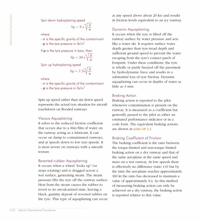
Hydroplaning (Aquaplaning)During the take-off roll on a runway contaminated with standing water (or equivalent) a “bow wave” may form so that the aeroplane may not be able to channel the water away from the tyres sufficiently to prevent a film of water from interposing between the tyre and the runway. When this occurs the wheels may stop rotating leading to scalding of the tyres, braking action is severely reduced, and the aeroplane may lose directional control. This situation is known as hydroplaning or aquaplaning. The speed at which this occurs depends on two features - the specific gravity of the contaminant and the tyre pressure linked by the formula:
3-10 Special Operational Procedures
OPER
ATION
AL PRO
CED
URES
pσ
Vp = 9 x
pσ
Vp = 7.7x
pσ
Vp = 34 x
Spin down hydroplaning speed
where- σ is the specific gravity of the contaminant- p is the tyre pressure in lb/in
If p is the tyre pressure in bars, than
Spin up hydroplaning speed
where- σ is the specific gravity of the contaminant- p is the tyre pressure in lb/in
2
2
Spin up speed rather than sin down speed represents the actual tyre situation for aircraft touchdown on flooded runways.
Viscous AquaplaningIt refers to the reduced friction coefficient that occurs due to a thin film of water on the runway acting as a lubricant. It can occur on damp to contaminated runways, and at speeds down to low taxi speeds. It is most severe on runways with a smooth texture.
Reverted-rubber AquaplaningIt occurs when a wheel “locks up” (or stops rotating) and is dragged across a wet surface, generating steam. The steam pressure lifts the tyre off the runway surface. Heat from the steam causes the rubber to revert to its unvulcanised state, leaving a black, gummy deposit of reverted rubber on the tyre. This type of aquaplaning can occur
at any speed above about 20 kts and results in friction levels equivalent to an icy runway.
Dynamic AquaplaningIt occurs when the tyre is lifted off the runway surface by water pressure and acts like a water ski. It requires surface water depth greater than tyre-tread depth and sufficient ground speed to prevent the water escaping from the tyre’s contact patch of footprint. Under these conditions, the tyre is wholly or partly buoyed off the pavement by hydrodynamic force and results in a substantial loss of tyre friction. Dynamic aquaplaning can occur in depths of water as little as 3 mm.
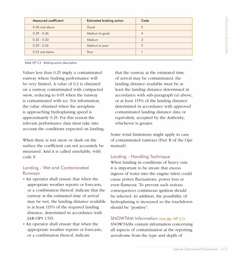
Braking ActionBraking action is reported to the pilot whenever contamination is present on the runway. It is measured as a coefficient but generally passed to the pilot as either an estimated performance indicator or in a code form. The equivalent braking actions are shown in table OP 3.2.
Braking Coefficient of FrictionThe braking coefficient is the ratio between the torque-limited and non-torque limited braking action on a dry runway and that of the same aeroplane at the same speed and mass on a wet runway. At low speeds there is effectively no difference (ratio 1.0) but by the time the aeroplane reaches approximately 160 kt the ratio has decreased to maintain a value of approximately 0.4. As this method of measuring braking action can only be achieved on a dry runway, the braking action is reported relative to this value.
Special Operational Procedures 3-11
OPER
ATION
AL PRO
CED
URES
Values less than 0.25 imply a contaminated runway where braking performance will be very limited. A value of 0.2 is obtained on a runway contaminated with compacted snow, reducing to 0.05 when the runway is contaminated with ice. For information, the value obtained when the aeroplane is approaching hydroplaning speed is approximately 0.25. For this reason the relevant performance data must take into account the conditions expected on landing.
When there is wet snow or slush on the surface the coefficient can not accurately be measured. And it is called unreliable, with code 9.
Landing - Wet and Contaminated Runways• An operator shall ensure that when the
appropriate weather reports or forecasts, or a combination thereof, indicate that the runway at the estimated time of arrival may be wet, the landing distance available is at least 115% of the required landing distance, determined in accordance with JAR-OPS 1.515.
• An operator shall ensure that when the appropriate weather reports or forecasts, or a combination thereof, indicate
that the runway at the estimated time of arrival may be contaminated, the landing distance available must be at least the landing distance determined in accordance with sub-paragraph (a) above, or at least 115% of the landing distance determined in accordance with approved contaminated landing distance data or equivalent, accepted by the Authority, whichever is greater.
Some wind limitations might apply in case of contaminated runways (Part B of the Ops manual).
Landing - Handling TechniqueWhen landing in conditions of heavy rain it is important to be aware that excess ingress of water into the engine inlets could cause power fluctuations, power loss or even flameout. To prevent such serious consequences continuous ignition should be selected. In addition, the possibility of hydroplaning is increased so the touchdown should be “positive”.
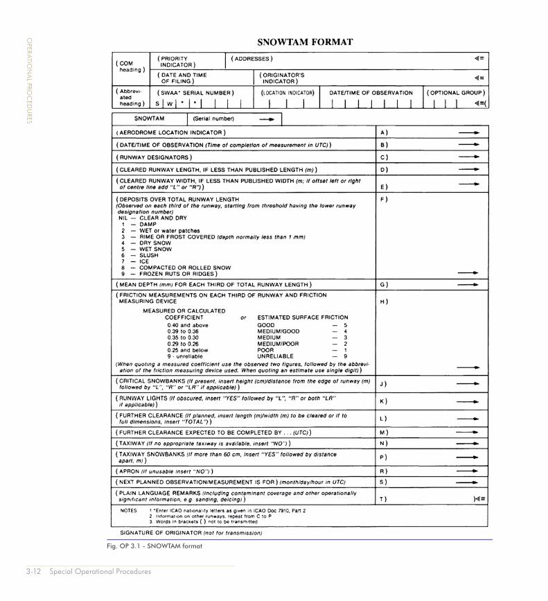
SNOWTAM Information (see fig. OP 3.1)
SNOWTAMs contain information concerning all aspects of contamination at the reporting aerodrome from the type and depth of
Table OP 3.2 Braking action description
Measured coefficient Estimated braking action Code
0.35 - 0.30
0.40 and above
0.39 - 0.36
0.29 - 0.26
0.25 and below
Medium
Good
Medium to good
Medium to poor
Poor
5
4
3
2
1
3-12 Special Operational Procedures
OPER
ATION
AL PRO
CED
URES
Fig. OP 3.1 - SNOWTAM format
Related Documents