3. Installation 3 • 1 EPDM Installation The information provided within this chapter may assist the contractor to install the Firestone EPDM Systems in accordance with Firestone’s requirements. It may also help him and the designer to inspect the completed installation. For a more practical use, we collected the information in a chronological order. Each phase of the installation is illustrated with one or more 3-dimensional drawings. The reader may consult the 2-dimensional illustrations in chapter 5 when additional information is required. This chapter contains the following sections: 1 Membrane Installation .................................................. p. 3. 3 2 Splicing ............................................................. p. 3. 14 3 Base Tie-in ........................................................... p. 3. 32 4 Wall Flashing ......................................................... p. 3. 38 5 Corners ............................................................. p. 3. 44 6 Pipe Penetrations ...................................................... p. 3. 51 7 Drains and Scuppers.................................................... p. 3. 58 8 Expansion Joints ....................................................... p. 3. 62 9 Roof Edges........................................................... p. 3. 64 10 Wall Terminations ...................................................... p. 3. 67 11 Membrane Repair ..................................................... p. 3. 71 12 Miscellaneous......................................................... p. 3. 73 3 Installation

Welcome message from author
This document is posted to help you gain knowledge. Please leave a comment to let me know what you think about it! Share it to your friends and learn new things together.
Transcript
3. In
stalla
tion
3 • 1EPDM Installation
The information provided within this chapter may assist the contractor to install the Firestone EPDM
Systems in accordance with Firestone’s requirements. It may also help him and the designer to inspect
the completed installation. For a more practical use, we collected the information in a chronological
order. Each phase of the installation is illustrated with one or more 3-dimensional drawings. The reader
may consult the 2-dimensional illustrations in chapter 5 when additional information is required.
This chapter contains the following sections:
1 Membrane Installation . . . . . . . . . . . . . . . . . . . . . . . . . . . . . . . . . . . . . . . . . . . . . . . . . . p. 3. 3
2 Splicing . . . . . . . . . . . . . . . . . . . . . . . . . . . . . . . . . . . . . . . . . . . . . . . . . . . . . . . . . . . . . p. 3. 14
3 Base Tie-in . . . . . . . . . . . . . . . . . . . . . . . . . . . . . . . . . . . . . . . . . . . . . . . . . . . . . . . . . . . p. 3. 32
4 Wall Flashing . . . . . . . . . . . . . . . . . . . . . . . . . . . . . . . . . . . . . . . . . . . . . . . . . . . . . . . . . p. 3. 38
5 Corners . . . . . . . . . . . . . . . . . . . . . . . . . . . . . . . . . . . . . . . . . . . . . . . . . . . . . . . . . . . . . p. 3. 44
6 Pipe Penetrations . . . . . . . . . . . . . . . . . . . . . . . . . . . . . . . . . . . . . . . . . . . . . . . . . . . . . . p. 3. 51
7 Drains and Scuppers. . . . . . . . . . . . . . . . . . . . . . . . . . . . . . . . . . . . . . . . . . . . . . . . . . . . p. 3. 58
8 Expansion Joints. . . . . . . . . . . . . . . . . . . . . . . . . . . . . . . . . . . . . . . . . . . . . . . . . . . . . . . p. 3. 62
9 Roof Edges. . . . . . . . . . . . . . . . . . . . . . . . . . . . . . . . . . . . . . . . . . . . . . . . . . . . . . . . . . . p. 3. 64
10 Wall Terminations. . . . . . . . . . . . . . . . . . . . . . . . . . . . . . . . . . . . . . . . . . . . . . . . . . . . . . p. 3. 67
11 Membrane Repair . . . . . . . . . . . . . . . . . . . . . . . . . . . . . . . . . . . . . . . . . . . . . . . . . . . . . p. 3. 71
12 Miscellaneous. . . . . . . . . . . . . . . . . . . . . . . . . . . . . . . . . . . . . . . . . . . . . . . . . . . . . . . . . p. 3. 73
3 Installation

3.
Inst
all
ati
on
3 • 2EPDM Installation
3. In
stalla
tion
3 • 3EPDM Installation
3.1 Membrane Installation
3.1.1 Membrane Installation - General
Firestone recommends for each system the following panel widths.
System Panel width (m)
Ballasted-Inverted 3.05 - 6.10 - 7.62 - 9.15 - 12.20 - 15.25
Fully Adhered 3.05 - 5.08 - 6.10
R.M.A. 5.08 - 6.10 - 9.15
M.A.S. 6.10 - 7.62 - 9.15 - 12.20
B.I.S. 2.28 - 3.05
However, cold weather can affect the workability of the membrane. Specifically, the low talc coating
and tight, firm packaging of the membrane may extend the time required for the membrane to relax
during winter months.
For Fully Adhered systems, fold lines remaining in the membrane during cold weather installation will
make smooth bonding to the substrate difficult. Firestone therefore recommends to utilize standard
3.05 m or 5.08 m wide fold-free panels.
R.M.A. systems also can be affected by cold weather, when using large panels that must be unfolded.
Firestone recommends for cold weather applications the use of fold-free (up to 5.08 m wide) or one-
fold panels (up to 9.15 m wide).
Prior to the installation of the roofing membrane, the contractor must check if the roof substrate
complies with Firestone’s design instructions. Any defects in the substrate need to be corrected and
the final surface has to be prepared to meet the requirements previously outlined. It is important that
the substrate is free of any sharp objects and/or products that may damage the membrane. Wipe the
substrate and install a protection fleece when required.
Place the EPDM roll as close as possible to its final position. It is easier to locate the roll in this position
than to have to reposition the EPDM panels after they have been unrolled. The direction for unrolling
the sheet is marked on the wrapper.
Inspect the wrapper and EPDM roll for damage before and during the installation. All membranes shall
be unrolled, unfolded and positioned over the roof substrate without stretching. The panels can be
moved sideways over the substrate by floating and allowing air underneath. Prior to any attachment,
cutting or splicing, each panel shall be allowed to relax a minimum of 30 minutes. Bigger panels (12.20
– 15.25 m wide) or cold weather application require more time (45 min.) for relaxation. Cut a cross-
shaped opening above every drain to evacuate excess of ponding water, in case of sudden rainfall.
3.
Inst
all
ati
on
3 • 4EPDM Installation
The EPDM panels shall be installed in a fashion so that field and flashing splices are installed to shed
water. Straight cuts are very important for a neat and easy application. Firestone recommends to use
scissors, markers and chalklines to achieve this. Do not use cutters.
Allow ample material for splicing with the overlap of adjoining sheets determined by the type of seam
and tie-ins. The tie-in material will be determined by the applicable detail. Provide an extra 150 mm of
membrane at roof edges and wall terminations to facilitate final positioning.
Temporary ballasting during installation may be required to keep the membrane in place until it is secu-
red to the substrate. Suggested temporary ballasting includes sand bags and other non-abrasive mate-
rials such as rubber tires, etc. Never leave the project without temporary ballasting the loose laid sheets.
3.1.2 Membrane Installation With Ballast
Applicability
This technique is applicable for ballasted and inverted systems.
Installation Instructions
Position adjoining sheets with a minimum overlap of 100 mm and allow to relax. Cover loosely laid
roofing sections as soon as possible with:
Gravel, in the form of round, smooth, river washed aggregate without broken pieces of adequate
size (nominal 16-32 mm). Make sure that the roofing membrane is completely covered. A ballast of
minimum 50 kg/m2 is required. However this may not always provide complete membrane coverage
or meet local requirements.
Graduated, crushed gravel. This type of ballast contains broken pieces and may damage the
EPDM membrane during installation. Firestone therefore recommends installing a geotextile
(min. 200 gr/m2) between ballast and membrane.
Concrete pavers, with smooth trowel finish. Consult local regulations and/or paver supplier
guidelines for maximum spacing between the pavers. Install a protection fleece or additional layer
of EPDM membrane directly beneath the concrete pavers.
Other types of ballast may be used (poured concrete, etc.) for other types of applications (parking
decks, etc.) but require a specific study. Consult local standards for type, adequate size, and
minimum weight of ballast and consult Firestone’s Technical Department for appropriate detailing.
In case of re-roofing, existing gravel may be re-used on the new roofing system provided it is of
adequate size and weight. It is recommended to install a geotextile (min. 200 gr/m2) between the
EPDM membrane and the recovered gravel.
Do not stock pile ballast on the roof deck. Spread the ballast over the EPDM membrane as specified,
using soft tools (rubber-tyre buggies, squeegees, etc.), avoid direct contact with the membrane when
projected. Spread the ballast around details by hand/foot so as to not damage the freshly installed
detail. Any ballast that is displaced by a walkway pad, should be distributed around the pad so as to
maintain the specified average coverage rate.
On roofs with a flat edge, the installation of rubber walkway pads within 3 m of the roof edge is not
allowed. Use concrete pavers.
3. In
stalla
tion
3 • 5EPDM Installation
For Inverted Systems, install the extruded polystyrene insulation directly over the EPDM membrane. The
insulation boards shall be installed within 6 mm of all projections. Do not bond the insulation boards
to the membrane or to each other. Unroll a protection mat over the insulation overlapping at side laps
a minimum of 100 mm and at end laps a minimum of 150 mm. The mat shall extend up at all vertical
penetrations 10 mm above the ballast.
3.1.3 Membrane Installation With Bonding Adhesive
Applicability
This technique is applicable for Fully Adhered systems and as an alternative to mechanical attachment
in the perimeter zones of the mechanically attached systems: R.M.A., M.A.S. and B.I.S.
Installation Instructions
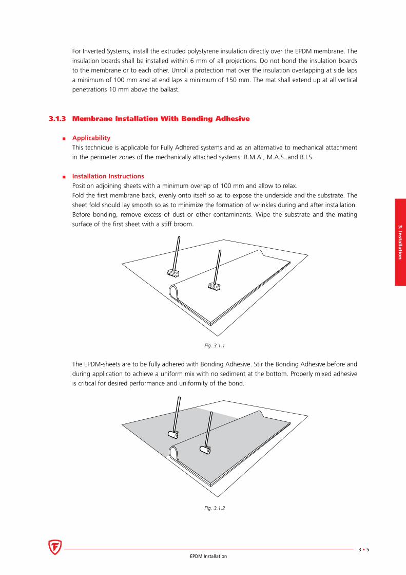
Position adjoining sheets with a minimum overlap of 100 mm and allow to relax.
Fold the first membrane back, evenly onto itself so as to expose the underside and the substrate. The
sheet fold should lay smooth so as to minimize the formation of wrinkles during and after installation.
Before bonding, remove excess of dust or other contaminants. Wipe the substrate and the mating
surface of the first sheet with a stiff broom.
Fig. 3.1.1
The EPDM-sheets are to be fully adhered with Bonding Adhesive. Stir the Bonding Adhesive before and
during application to achieve a uniform mix with no sediment at the bottom. Properly mixed adhesive
is critical for desired performance and uniformity of the bond.
Fig. 3.1.2

3.
Inst
all
ati
on
3 • 6EPDM Installation
The Bonding Adhesive must be roller applied in a thin even coat on both mating surfaces. Firestone
recommends a two-man operation to facilitate equal drying times. Avoid globs or puddles of adhesive
during application. An excess of adhesive will prolong the drying time and reduce production. The use
of Superspreader equipment can speed up production and increase coverage due to a better distribu-
tion of the adhesive. When applying the adhesive manually, use large solvent resistant rollers (200 to
250 mm wide) with short hairs to apply the adhesive evenly. Care must be taken not to apply Bonding
Adhesive over an area that is to be cleaned later and spliced to another sheet or QuickSeam Reinforced
Fastening Perimeter Strip. Use a chalkline to mark the splicing area that has to remain clean.
See Technical Data sheet for information about recommended coverage rates.
Wait until the adhesive is tacky. Drying time will differ with various climatic conditions and coverage
rate. Never use a hot air dryer to accelerate this process. Touch the surface with a clean, dry finger to
check the adhesive for dryness. As you are touching the adhesive, push straight down to check the mass
of adhesive under its surface for stringing.
2
1
Fig. 3.1.3
Push forward on the adhesive at an angle to ensure that it is dry throughout its thickness. If either
motion exposes wet or stringy adhesive when the finger is lifted then it is not ready for mating.
As the first sheet is flashing off, lay out the adjoining sheets and allow them to relax.
Bond the membrane, starting at the fold. Roll the previously coated portion of the sheet into the coated
substrate, slowly and evenly to minimize wrinkles.
Fig. 3.1.4
3. In
stalla
tion
3 • 7EPDM Installation
Compress the bonded half to the substrate with a stiff brush to ensure proper contact. Extra compres-
sion will strengthen the bond. Repeat the bonding procedure to complete the bonding of the sheet.
Take special precautions when the outside temperature is below 10°C. Certain combinations of tempe-
rature and humidity may cause condensation on the surface of the Bonding Adhesive. If this condition
occurs, do not mate the surfaces. Wait until the ambient air conditions no longer cause condensation,
dry the surface with clean, dry rags, apply a thin additional layer of adhesive and proceed.
As an alternative to the contact adhesion application method, outlined above, Water Based Bonding
Adhesive may also be mated while still wet directly over plywood or OSB substrates only. Apply Water
Based Bonding Adhesive over plywood or OSB with a solvent resistant paint roller, taking care to com-
pletely cover the plywood or OSB substrate evenly to avoid globs and puddles of adhesive. The EPDM
membrane shall be mated as soon as possible after the bonding adhesive is applied by rolling the
membrane in place over the plywood or OSB. To ensure proper adhesion, compress the bonded portion
of the sheet to the substrate with a stiff push broom. The optional Wet Mating Method is only appli-
cable when membrane is not exposed to any wind stresses for 48 hours and not exposed to freezing
temperatures for minimum 48 hours. See Technical Data Sheet for information about recommended
coverage rates.
3.1.4 Membrane Installation - System R.M.A.
Applicability
This technique is applicable for mechanically anchored system R.M.A..
Installation Instructions
The QuickSeam R.M.A. strips are mechanically attached to the substrate using batten strips or approved
plates and fasteners. The EPDM membrane is then adhered to these strips using conventional seaming
techniques.
Consult the wind design calculation and QuickSeam R.M.A. strip layout for information about the
position of the R.M.A. strips and the size of local wind zones (zones of high wind pressure, such as
perimeter, ridge, base of roof step, base of penthouse, etc.).
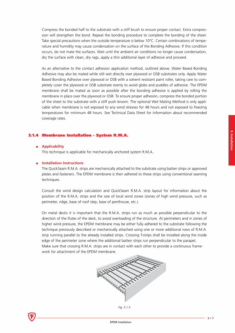
On metal decks it is important that the R.M.A. strips run as much as possible perpendicular to the
direction of the flutes of the deck, to avoid overloading of the structure. At perimeters and in zones of
higher wind pressure, the EPDM membrane may be either fully adhered to the substrate following the
technique previously described or mechanically attached using one or more additional rows of R.M.A.
strip running parallel to the already installed strips. Crossing T-strips shall be installed along the inside
edge of the perimeter zone where the additional batten strips run perpendicular to the parapet.
Make sure that crossing R.M.A. strips are in contact with each other to provide a continuous frame-
work for attachment of the EPDM membrane.
Fig. 3.1.5
3.
Inst
all
ati
on
3 • 8EPDM Installation
Install the QuickSeam R.M.A. strips as required using approved plates and fasteners or batten strips and
fasteners. When using plates, automatic fastening equipment can provide for a time-saving installation. For
more information on the installation of batten strips, consult the section on the M.A.S. system hereafter.
Prior to seaming the EPDM membrane to the R.M.A. strips, make sure that the EPDM panels lay
smoothly and without any wrinkles. The EPDM membrane will be adhered to the QuickSeam R.M.A.
strips as outlined in the following chapter.
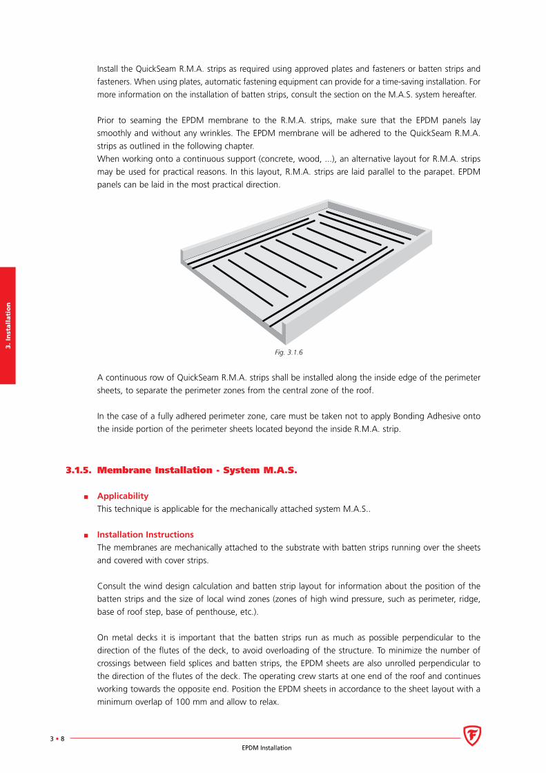
When working onto a continuous support (concrete, wood, ...), an alternative layout for R.M.A. strips
may be used for practical reasons. In this layout, R.M.A. strips are laid parallel to the parapet. EPDM
panels can be laid in the most practical direction.
Fig. 3.1.6
A continuous row of QuickSeam R.M.A. strips shall be installed along the inside edge of the perimeter
sheets, to separate the perimeter zones from the central zone of the roof.
In the case of a fully adhered perimeter zone, care must be taken not to apply Bonding Adhesive onto
the inside portion of the perimeter sheets located beyond the inside R.M.A. strip.
3.1.5. Membrane Installation - System M.A.S.
Applicability
This technique is applicable for the mechanically attached system M.A.S..
Installation Instructions
The membranes are mechanically attached to the substrate with batten strips running over the sheets
and covered with cover strips.
Consult the wind design calculation and batten strip layout for information about the position of the
batten strips and the size of local wind zones (zones of high wind pressure, such as perimeter, ridge,
base of roof step, base of penthouse, etc.).
On metal decks it is important that the batten strips run as much as possible perpendicular to the
direction of the flutes of the deck, to avoid overloading of the structure. To minimize the number of
crossings between field splices and batten strips, the EPDM sheets are also unrolled perpendicular to
the direction of the flutes of the deck. The operating crew starts at one end of the roof and continues
working towards the opposite end. Position the EPDM sheets in accordance to the sheet layout with a
minimum overlap of 100 mm and allow to relax.
3. In
stalla
tion
3 • 9EPDM Installation
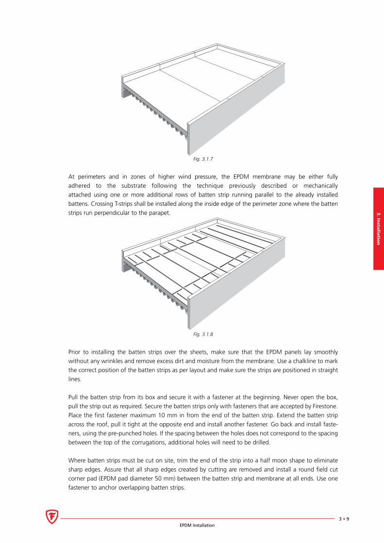
Fig. 3.1.7
At perimeters and in zones of higher wind pressure, the EPDM membrane may be either fully
adhered to the substrate following the technique previously described or mechanically
attached using one or more additional rows of batten strip running parallel to the already installed
battens. Crossing T-strips shall be installed along the inside edge of the perimeter zone where the batten
strips run perpendicular to the parapet.
Fig. 3.1.8
Prior to installing the batten strips over the sheets, make sure that the EPDM panels lay smoothly
without any wrinkles and remove excess dirt and moisture from the membrane. Use a chalkline to mark
the correct position of the batten strips as per layout and make sure the strips are positioned in straight
lines.
Pull the batten strip from its box and secure it with a fastener at the beginning. Never open the box,
pull the strip out as required. Secure the batten strips only with fasteners that are accepted by Firestone.
Place the first fastener maximum 10 mm in from the end of the batten strip. Extend the batten strip
across the roof, pull it tight at the opposite end and install another fastener. Go back and install faste-
ners, using the pre-punched holes. If the spacing between the holes does not correspond to the spacing
between the top of the corrugations, additional holes will need to be drilled.
Where batten strips must be cut on site, trim the end of the strip into a half moon shape to eliminate
sharp edges. Assure that all sharp edges created by cutting are removed and install a round field cut
corner pad (EPDM pad diameter 50 mm) between the batten strip and membrane at all ends. Use one
fastener to anchor overlapping batten strips.
3.
Inst
all
ati
on
3 • 10EPDM Installation
The fastener must be properly engaged in the deck. Use caution not to overdrive fasteners, as this will
cause buckling of the batten strip between the fasteners and reduce the pull-out value of the fastener.
If the strip kinks, loosen the screw slightly. An electric screw gun with an automatic clutch control or
an automatic installation tool is recommended. Once the tools have been set, all fastener installation
will be consistent.
Crossing strips should not overlap. Stop the strips at 250 mm away from each other so that cover strips
can be installed without overlapping.
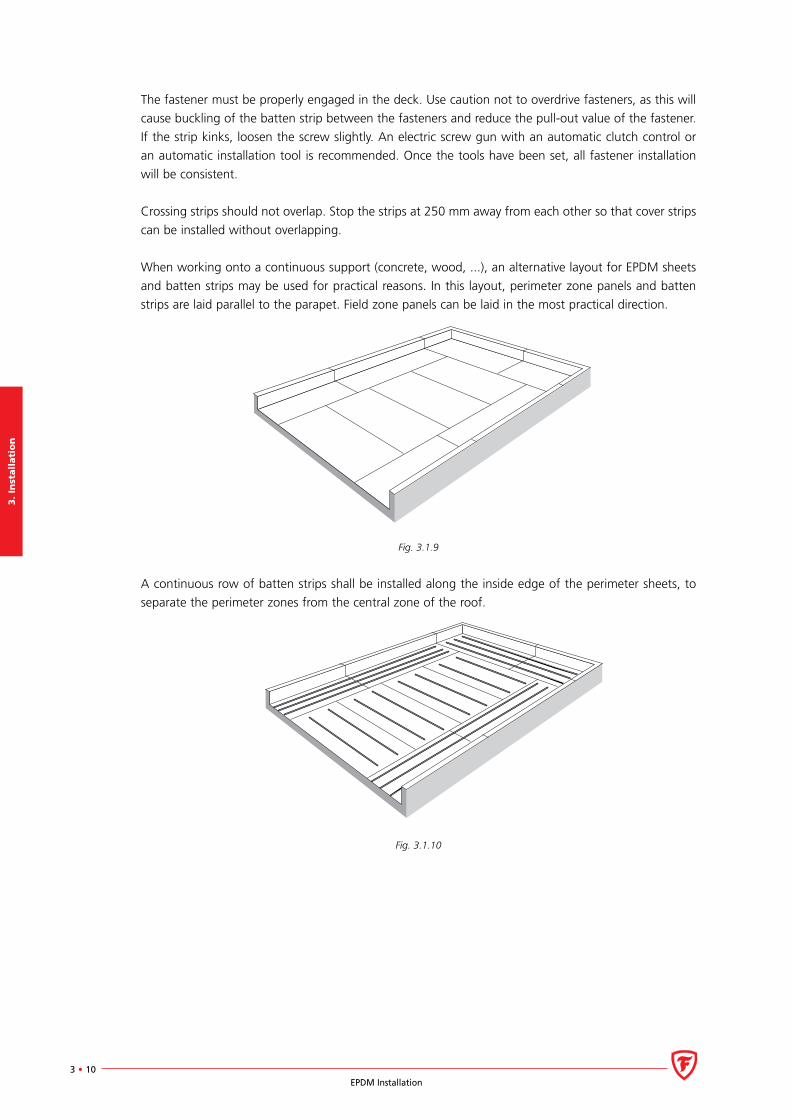
When working onto a continuous support (concrete, wood, ...), an alternative layout for EPDM sheets
and batten strips may be used for practical reasons. In this layout, perimeter zone panels and batten
strips are laid parallel to the parapet. Field zone panels can be laid in the most practical direction.
Fig. 3.1.9
A continuous row of batten strips shall be installed along the inside edge of the perimeter sheets, to
separate the perimeter zones from the central zone of the roof.
Fig. 3.1.10
3. In
stalla
tion
3 • 11EPDM Installation
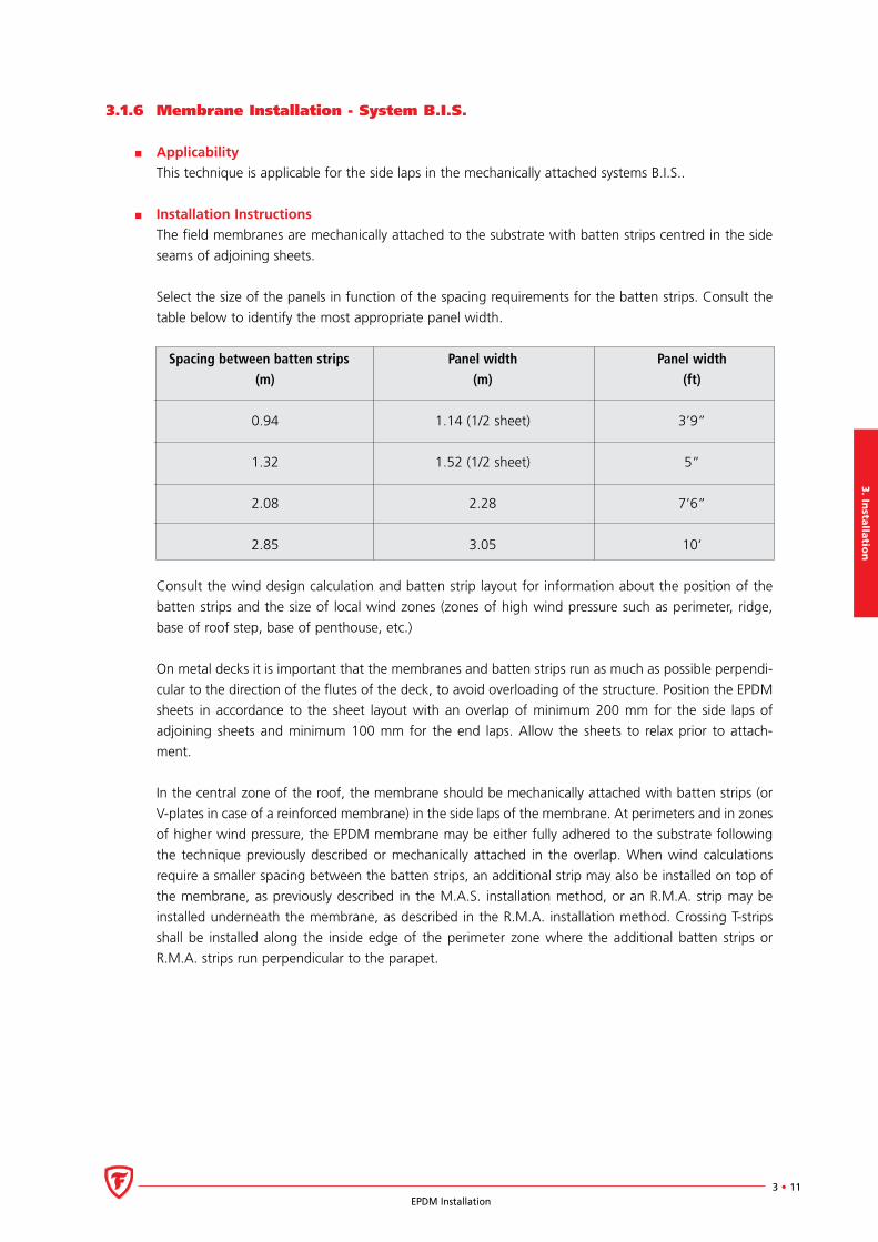
3.1.6 Membrane Installation - System B.I.S.
Applicability
This technique is applicable for the side laps in the mechanically attached systems B.I.S..
Installation Instructions
The field membranes are mechanically attached to the substrate with batten strips centred in the side
seams of adjoining sheets.
Select the size of the panels in function of the spacing requirements for the batten strips. Consult the
table below to identify the most appropriate panel width.
Spacing between batten strips Panel width Panel width (m) (m) (ft)
0.94 1.14 (1/2 sheet) 3’9”
1.32 1.52 (1/2 sheet) 5”
2.08 2.28 7’6”
2.85 3.05 10’
Consult the wind design calculation and batten strip layout for information about the position of the
batten strips and the size of local wind zones (zones of high wind pressure such as perimeter, ridge,
base of roof step, base of penthouse, etc.)
On metal decks it is important that the membranes and batten strips run as much as possible perpendi-
cular to the direction of the flutes of the deck, to avoid overloading of the structure. Position the EPDM
sheets in accordance to the sheet layout with an overlap of minimum 200 mm for the side laps of
adjoining sheets and minimum 100 mm for the end laps. Allow the sheets to relax prior to attach-
ment.
In the central zone of the roof, the membrane should be mechanically attached with batten strips (or
V-plates in case of a reinforced membrane) in the side laps of the membrane. At perimeters and in zones
of higher wind pressure, the EPDM membrane may be either fully adhered to the substrate following
the technique previously described or mechanically attached in the overlap. When wind calculations
require a smaller spacing between the batten strips, an additional strip may also be installed on top of
the membrane, as previously described in the M.A.S. installation method, or an R.M.A. strip may be
installed underneath the membrane, as described in the R.M.A. installation method. Crossing T-strips
shall be installed along the inside edge of the perimeter zone where the additional batten strips or
R.M.A. strips run perpendicular to the parapet.
3.
Inst
all
ati
on
3 • 12EPDM Installation
Fig. 3.1.11
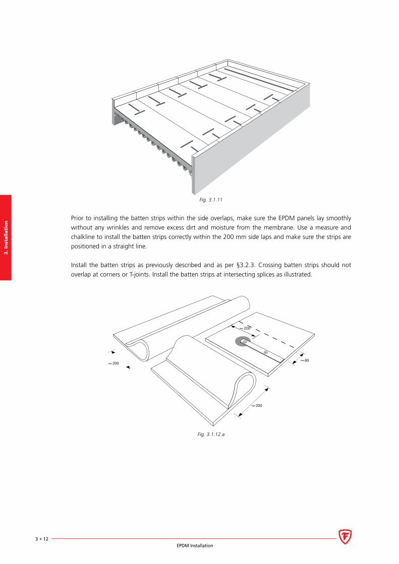
Prior to installing the batten strips within the side overlaps, make sure the EPDM panels lay smoothly
without any wrinkles and remove excess dirt and moisture from the membrane. Use a measure and
chalkline to install the batten strips correctly within the 200 mm side laps and make sure the strips are
positioned in a straight line.
Install the batten strips as previously described and as per §3.2.3. Crossing batten strips should not
overlap at corners or T-joints. Install the batten strips at intersecting splices as illustrated.
200
200
200
80
Fig. 3.1.12.a
3. In
stalla
tion
3 • 13EPDM Installation
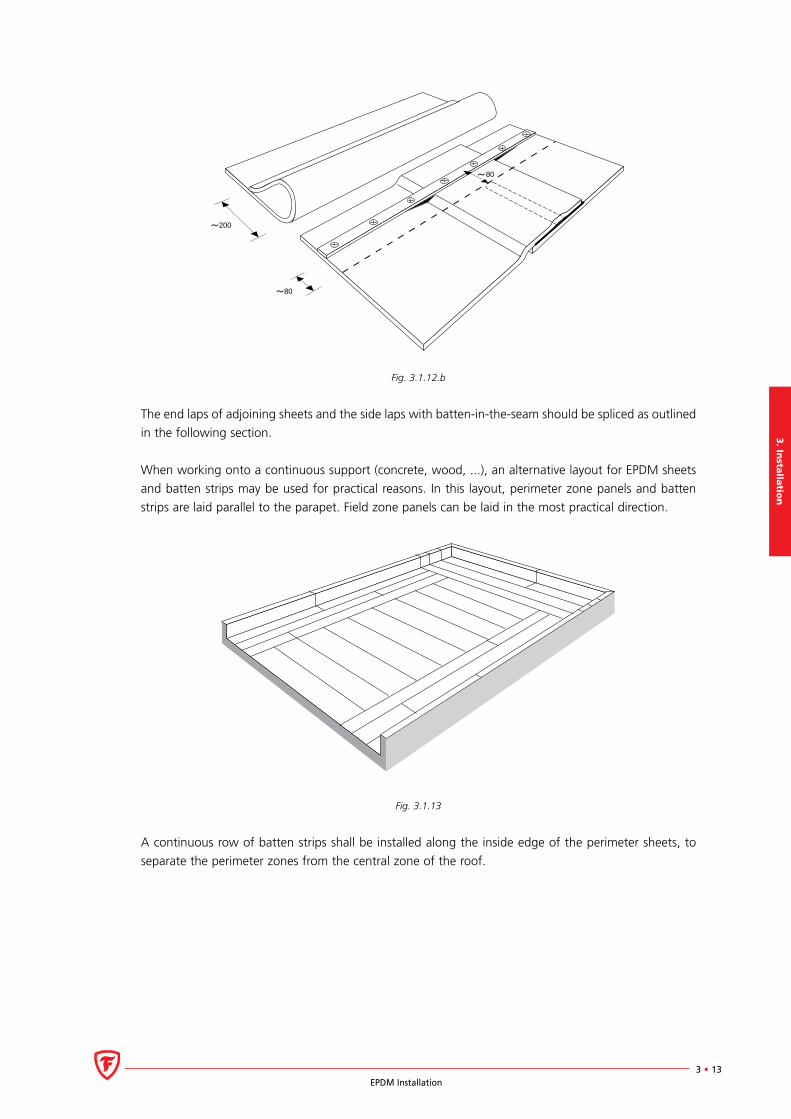
200
80
80
Fig. 3.1.12.b
The end laps of adjoining sheets and the side laps with batten-in-the-seam should be spliced as outlined
in the following section.
When working onto a continuous support (concrete, wood, ...), an alternative layout for EPDM sheets
and batten strips may be used for practical reasons. In this layout, perimeter zone panels and batten
strips are laid parallel to the parapet. Field zone panels can be laid in the most practical direction.
Fig. 3.1.13
A continuous row of batten strips shall be installed along the inside edge of the perimeter sheets, to
separate the perimeter zones from the central zone of the roof.
3.
Inst
all
ati
on
3 • 14EPDM Installation
3.2 Splicing
3.2.1 Splicing General
There are two types of seams in the Firestone EPDM roofing systems:
Factory seams: when splicing is performed during the production of the EPDM sheet prior to vulca-
nisation. The material of the seam is homogeneous and 100 % cured. This results in large, seamless
EPDM panels, so as to minimize the number of field splices.
Field seams: when splicing is performed on site with a self-adhering Splice Tape.
In this section particular attention is given to the Firestone EPDM field seams and the related splicing
operations in the different Firestone EPDM systems.
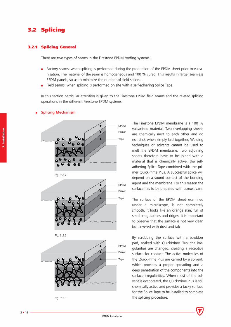
Splicing Mechanism
The Firestone EPDM membrane is a 100 %
vulcanised material. Two overlapping sheets
are chemically inert to each other and do
not stick when simply laid together. Welding
techniques or solvents cannot be used to
melt the EPDM membrane. Two adjoining
sheets therefore have to be joined with a
material that is chemically active, the self-
adhering Splice Tape combined with the pri-
mer QuickPrime Plus. A successful splice will
depend on a sound contact of the bonding
agent and the membrane. For this reason the
surface has to be prepared with utmost care.
The surface of the EPDM sheet examined
under a microscope, is not completely
smooth, it looks like an orange skin, full of
small irregularities and ridges. It is important
to observe that the surface is not very clean
but covered with dust and talc.
By scrubbing the surface with a scrubber
pad, soaked with QuickPrime Plus, the irre-
gularities are changed, creating a receptive
surface for contact. The active molecules of
the QuickPrime Plus are carried by a solvent,
which provides a proper spreading and a
deep penetration of the components into the
surface irregularities. When most of the sol-
vent is evaporated, the QuickPrime Plus is still
chemically active and provides a tacky surface
for the Splice Tape to be installed to complete
the splicing procedure.
EPDM
Primer
Tape
EPDM
Primer
Tape
EPDM
Primer
Tape
Fig. 3.2.3
Fig. 3.2.2
Fig. 3.2.1
3. In
stalla
tion
3 • 15EPDM Installation
In addition to the adhesion mechanism (attraction between adhesive and surface molecules) the
irregularities of the membrane surface are mechanically interlocked by the components of the
QuickPrime Plus. Both mechanisms create high-resistance molecular links. It will take 7 to 28 days for
the QuickPrime Plus to lose its remaining solvent and therefore complete the curing process.
Experience to date has demonstrated that the EPDM field splicing technique using Splice Tape and
QuickPrime Plus is very “roofer friendly”. This installation method satisfies the normal day-to-day
variations such as climatic conditions, different applicators and job conditions. The QuickScrubber kit,
QuickScrubber Plus Stand-up Tool and QuickTaper make the application of the primer and tape easy,
clean, quick and reliable.
The application techniques for the QuickPrime Plus, as described in the seaming procedures are also
applicable to the system details where other QuickSeam products are used, i.e. application of QuickSeam
FormFlash, QuickSeam Batten Cover Strip, QuickSeam R.M.A. Strip, base tie-in with QuickSeam
Reinforced Perimeter Fastening strip, flashing of metal edge profiles with QuickSeam Flashing, flashing
of pipe penetrations with QuickSeam Pipe boot, flashing of drains with QuickSeam SA Flashing, etc..
All splicing surfaces must be free of dirt, moisture and any other contaminants before the installation
of QuickSeam Products. When necessary, pre-clean with the cleaning agent Splice Wash prior to the
application of QuickPrime Plus.
Notes:
As an alternative to regular seaming and flashing procedures using QuickSeam products in combina-
tion with QuickPrime Plus, contact adhesives (Splice Adhesive) could also be used. It should be noted
however that adhesive seams are more critical than QuickSeam solutions. When applying the Splice
Adhesive option, the membrane should be cleaned using Splice Wash. Other cleaning products, such
as unleaded gasoline are not recommended. They may be contaminated with traces of products that
may react adversely with EPDM and fail to activate the surface in the same manner.
All seaming products (QuickSeam Splice Tape, QuickPrime Plus, sealants, ...) have product limitations.
Follow the technical specifications outlined in the Technical Information Sheets to ensure correct
application. Store all Firestone materials in their original sealed pails or unopened packages and
rotate perishable materials so that they are used prior to the end of their shelf life.
Firestone recommends storing primers and sealants at room temperature between 15°C and 25°C.
If exposed to lower temperatures, restore to room temperature during 3 to 4 hours prior to use.
Splicing activities may continue in cold weather provided adhesive, QuickPrime Plus and sealants are
at room temperature prior to application and are used within a 4-hour period after being taken to
the roof. Stir primer thoroughly before and during use. This is a critical step that assures that the
material performs properly; do not alter the products by adding solvents.
Attention must be paid to primer in warm weather conditions. Extreme warm weather may dry out
the solvents quickly. This can be avoided by protecting the pails against hot temperatures by instal-
ling an insulation board between can and membrane on hot summer days and sheltering cans from
direct sunlight. Any questions about the condition of a product should be discussed with Firestone
Building Products’ Technical Department. Please note the production date of the product.
Some types of insulation materials such as extruded and expanded polystyrene should not come
into contact with QuickPrime Plus. It is recommended to install a 500 mm wide strip of polyethylene
underneath the membrane in the splicing area, to protect these insulation materials.
3.
Inst
all
ati
on
3 • 16EPDM Installation
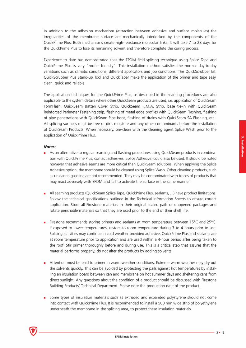
3.2.2 Splicing With 76 mm (3”) Splice Tape
76
Fig. 3.2.4
Applicability
Firestone’s 76 mm (3”) Splice Tape is designed for field splices in all systems as indicated in the table
below.
System Application
Ballasted, Inverted, Adhered All seams
R.M.A., M.A.S. All seams
B.I.S. End laps only (152 mm Tape for side laps)
All systems Laps EPDM flashings
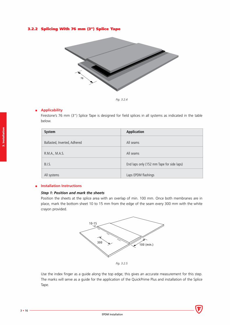
Installation Instructions
Step 1: Position and mark the sheets
Position the sheets at the splice area with an overlap of min. 100 mm. Once both membranes are in
place, mark the bottom sheet 10 to 15 mm from the edge of the seam every 300 mm with the white
crayon provided.
300
10-15
100 (min.)
Fig. 3.2.5
Use the index finger as a guide along the top edge; this gives an accurate measurement for this step.
The marks will serve as a guide for the application of the QuickPrime Plus and installation of the Splice
Tape.
3. In
stalla
tion
3 • 17EPDM Installation
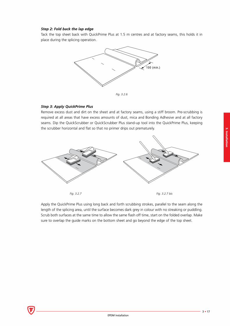
Step 2: Fold back the lap edge
Tack the top sheet back with QuickPrime Plus at 1.5 m centres and at factory seams, this holds it in
place during the splicing operation.
100 (min.)
Fig. 3.2.6
Step 3: Apply QuickPrime Plus
Remove excess dust and dirt on the sheet and at factory seams, using a stiff broom. Pre-scrubbing is
required at all areas that have excess amounts of dust, mica and Bonding Adhesive and at all factory
seams. Dip the QuickScrubber or QuickScrubber Plus stand-up tool into the QuickPrime Plus, keeping
the scrubber horizontal and flat so that no primer drips out prematurely.
Fig. 3.2.7 Fig. 3.2.7 bis
Apply the QuickPrime Plus using long back and forth scrubbing strokes, parallel to the seam along the
length of the splicing area, until the surface becomes dark grey in colour with no streaking or puddling.
Scrub both surfaces at the same time to allow the same flash off time, start on the folded overlap. Make
sure to overlap the guide marks on the bottom sheet and go beyond the edge of the top sheet.
3.
Inst
all
ati
on
3 • 18EPDM Installation
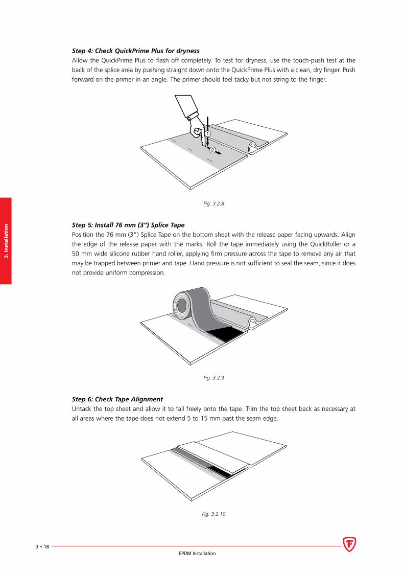
Step 4: Check QuickPrime Plus for dryness
Allow the QuickPrime Plus to flash off completely. To test for dryness, use the touch-push test at the
back of the splice area by pushing straight down onto the QuickPrime Plus with a clean, dry finger. Push
forward on the primer in an angle. The primer should feel tacky but not string to the finger.
2
1
Fig. 3.2.8
Step 5: Install 76 mm (3”) Splice Tape
Position the 76 mm (3”) Splice Tape on the bottom sheet with the release paper facing upwards. Align
the edge of the release paper with the marks. Roll the tape immediately using the QuickRoller or a
50 mm wide silicone rubber hand roller, applying firm pressure across the tape to remove any air that
may be trapped between primer and tape. Hand pressure is not sufficient to seal the seam, since it does
not provide uniform compression.
Fig. 3.2.9
Step 6: Check Tape Alignment
Untack the top sheet and allow it to fall freely onto the tape. Trim the top sheet back as necessary at
all areas where the tape does not extend 5 to 15 mm past the seam edge.
Fig. 3.2.10
3. In
stalla
tion
3 • 19EPDM Installation
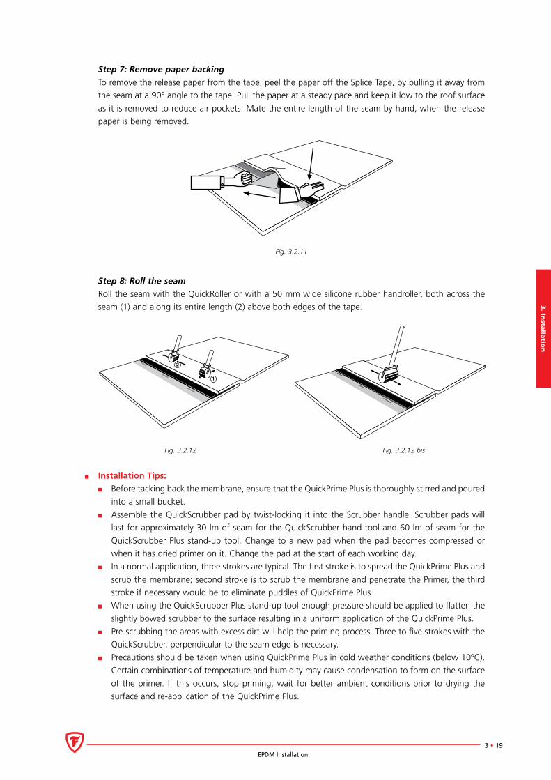
Step 7: Remove paper backing
To remove the release paper from the tape, peel the paper off the Splice Tape, by pulling it away from
the seam at a 90° angle to the tape. Pull the paper at a steady pace and keep it low to the roof surface
as it is removed to reduce air pockets. Mate the entire length of the seam by hand, when the release
paper is being removed.
Fig. 3.2.11
Step 8: Roll the seam
Roll the seam with the QuickRoller or with a 50 mm wide silicone rubber handroller, both across the
seam (1) and along its entire length (2) above both edges of the tape.
Fig. 3.2.12 Fig. 3.2.12 bis
Installation Tips:
Before tacking back the membrane, ensure that the QuickPrime Plus is thoroughly stirred and poured
into a small bucket.
Assemble the QuickScrubber pad by twist-locking it into the Scrubber handle. Scrubber pads will
last for approximately 30 lm of seam for the QuickScrubber hand tool and 60 lm of seam for the
QuickScrubber Plus stand-up tool. Change to a new pad when the pad becomes compressed or
when it has dried primer on it. Change the pad at the start of each working day.
In a normal application, three strokes are typical. The first stroke is to spread the QuickPrime Plus and
scrub the membrane; second stroke is to scrub the membrane and penetrate the Primer, the third
stroke if necessary would be to eliminate puddles of QuickPrime Plus.
When using the QuickScrubber Plus stand-up tool enough pressure should be applied to flatten the
slightly bowed scrubber to the surface resulting in a uniform application of the QuickPrime Plus.
Pre-scrubbing the areas with excess dirt will help the priming process. Three to five strokes with the
QuickScrubber, perpendicular to the seam edge is necessary.
Precautions should be taken when using QuickPrime Plus in cold weather conditions (below 10ºC).
Certain combinations of temperature and humidity may cause condensation to form on the surface
of the primer. If this occurs, stop priming, wait for better ambient conditions prior to drying the
surface and re-application of the QuickPrime Plus.
3.
Inst
all
ati
on
3 • 20EPDM Installation
Complete a test splice to determine the risks for condensation. Never use heat guns or torches to
accelerate the drying process of QuickPrime Plus. In normal conditions QuickPrime Plus will flash off
in 5 to 10 minutes, quicker in hot weather.
In hot weather Firestone recommends to apply QuickPrime Plus first onto the bottom sheet, to check
for dryness and to install the tape. After the tape has been rolled, apply QuickPrime Plus to the top
sheet, check for dryness, untack the top sheet and allow it to fall freely onto the tape. Then follow
instructions step 6 through 8 to complete the seam.
During the positioning of the tape on the bottom sheet, misalignment may occur. Stop the opera-
tion, cut the Splice Tape, make an overlap of minimum 25 mm with the end of the installed tape
and continue the alignment with the markings. Cutting the tape should be done with the tape
sandwiched between 2 pieces of release paper for a clean cut.
Any fishmouth that occurs during installation of the tape should be cut away and repaired with a
piece of QuickSeam FormFlash/Flashing, covering the perimeters of the cut by minimum 75 mm in all
directions.
After closing the seam, it is important to observe a continuous mark of primer beyond the fold line
of the top sheet.
When using the QuickRoller make sure to roll the seam along its length in a back and forth motion;
50 to 75 cm at a time until the seam is completely rolled.
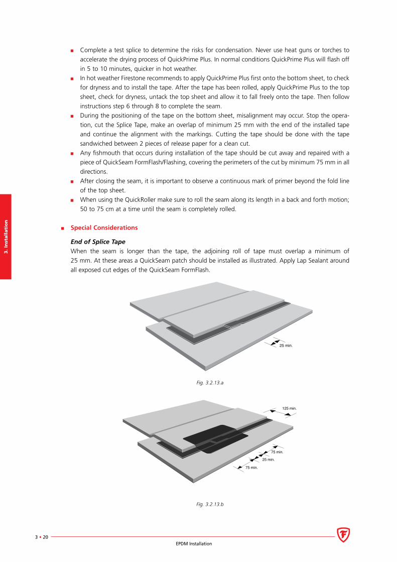
Special Considerations
End of Splice Tape
When the seam is longer than the tape, the adjoining roll of tape must overlap a minimum of
25 mm. At these areas a QuickSeam patch should be installed as illustrated. Apply Lap Sealant around
all exposed cut edges of the QuickSeam FormFlash.
25 min.
Fig. 3.2.13.a
75 min.
125 min.
75 min.
25 min.
Fig. 3.2.13.b
3. In
stalla
tion
3 • 21EPDM Installation
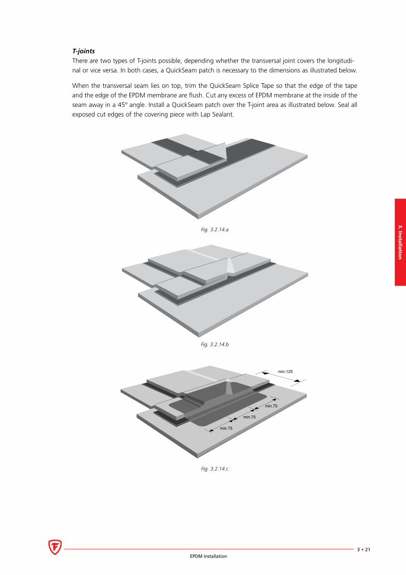
T-joints
There are two types of T-joints possible, depending whether the transversal joint covers the longitudi-
nal or vice versa. In both cases, a QuickSeam patch is necessary to the dimensions as illustrated below.
When the transversal seam lies on top, trim the QuickSeam Splice Tape so that the edge of the tape
and the edge of the EPDM membrane are flush. Cut any excess of EPDM membrane at the inside of the
seam away in a 45º angle. Install a QuickSeam patch over the T-joint area as illustrated below. Seal all
exposed cut edges of the covering piece with Lap Sealant.
Fig. 3.2.14.a
Fig. 3.2.14.b
min.75
min.75
min.125
min.75
Fig. 3.2.14.c
3.
Inst
all
ati
on
3 • 22EPDM Installation
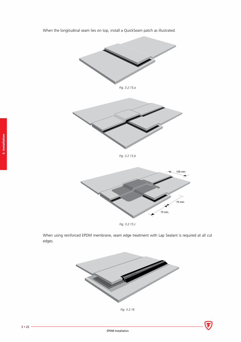
When the longitudinal seam lies on top, install a QuickSeam patch as illustrated.
Fig. 3.2.15.a
Fig. 3.2.15.b
125 min.
75 min.
75 min.
Fig. 3.2.15.c
When using reinforced EPDM membrane, seam edge treatment with Lap Sealant is required at all cut
edges.
Fig. 3.2.16
3. In
stalla
tion
3 • 23EPDM Installation
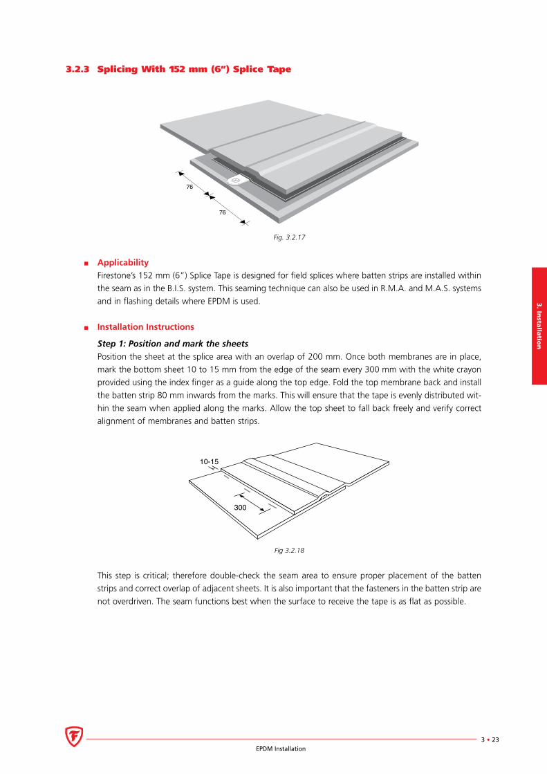
3.2.3 Splicing With 152 mm (6”) Splice Tape
76
76
Fig. 3.2.17
Applicability
Firestone’s 152 mm (6”) Splice Tape is designed for field splices where batten strips are installed within
the seam as in the B.I.S. system. This seaming technique can also be used in R.M.A. and M.A.S. systems
and in flashing details where EPDM is used.
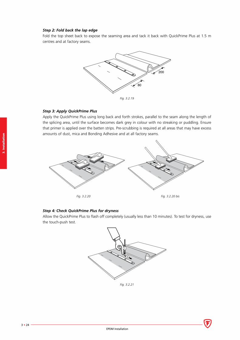
Installation Instructions
Step 1: Position and mark the sheets
Position the sheet at the splice area with an overlap of 200 mm. Once both membranes are in place,
mark the bottom sheet 10 to 15 mm from the edge of the seam every 300 mm with the white crayon
provided using the index finger as a guide along the top edge. Fold the top membrane back and install
the batten strip 80 mm inwards from the marks. This will ensure that the tape is evenly distributed wit-
hin the seam when applied along the marks. Allow the top sheet to fall back freely and verify correct
alignment of membranes and batten strips.
300
10-15
Fig 3.2.18
This step is critical; therefore double-check the seam area to ensure proper placement of the batten
strips and correct overlap of adjacent sheets. It is also important that the fasteners in the batten strip are
not overdriven. The seam functions best when the surface to receive the tape is as flat as possible.
3.
Inst
all
ati
on
3 • 24EPDM Installation
Step 2: Fold back the lap edge
Fold the top sheet back to expose the seaming area and tack it back with QuickPrime Plus at 1.5 m
centres and at factory seams.
80
200
Fig. 3.2.19
Step 3: Apply QuickPrime Plus
Apply the QuickPrime Plus using long back and forth strokes, parallel to the seam along the length of
the splicing area, until the surface becomes dark grey in colour with no streaking or puddling. Ensure
that primer is applied over the batten strips. Pre-scrubbing is required at all areas that may have excess
amounts of dust, mica and Bonding Adhesive and at all factory seams.
Fig. 3.2.20 Fig. 3.2.20 bis
Step 4: Check QuickPrime Plus for dryness
Allow the QuickPrime Plus to flash off completely (usually less than 10 minutes). To test for dryness, use
the touch-push test.
2
1
Fig. 3.2.21
3. In
stalla
tion
3 • 25EPDM Installation
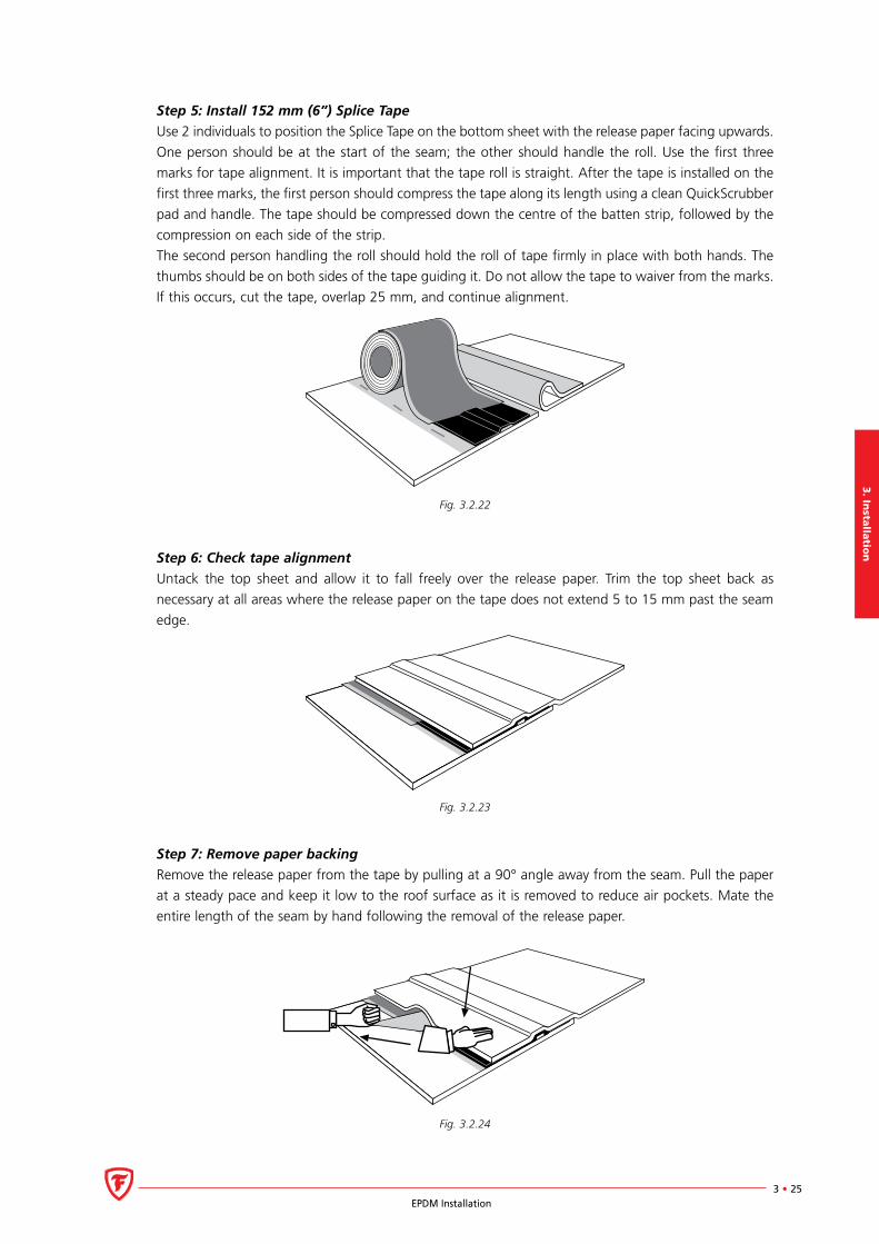
Step 5: Install 152 mm (6”) Splice Tape
Use 2 individuals to position the Splice Tape on the bottom sheet with the release paper facing upwards.
One person should be at the start of the seam; the other should handle the roll. Use the first three
marks for tape alignment. It is important that the tape roll is straight. After the tape is installed on the
first three marks, the first person should compress the tape along its length using a clean QuickScrubber
pad and handle. The tape should be compressed down the centre of the batten strip, followed by the
compression on each side of the strip.
The second person handling the roll should hold the roll of tape firmly in place with both hands. The
thumbs should be on both sides of the tape guiding it. Do not allow the tape to waiver from the marks.
If this occurs, cut the tape, overlap 25 mm, and continue alignment.
Fig. 3.2.22
Step 6: Check tape alignment
Untack the top sheet and allow it to fall freely over the release paper. Trim the top sheet back as
necessary at all areas where the release paper on the tape does not extend 5 to 15 mm past the seam
edge.
Fig. 3.2.23
Step 7: Remove paper backing
Remove the release paper from the tape by pulling at a 90° angle away from the seam. Pull the paper
at a steady pace and keep it low to the roof surface as it is removed to reduce air pockets. Mate the
entire length of the seam by hand following the removal of the release paper.
Fig. 3.2.24
3.
Inst
all
ati
on
3 • 26EPDM Installation
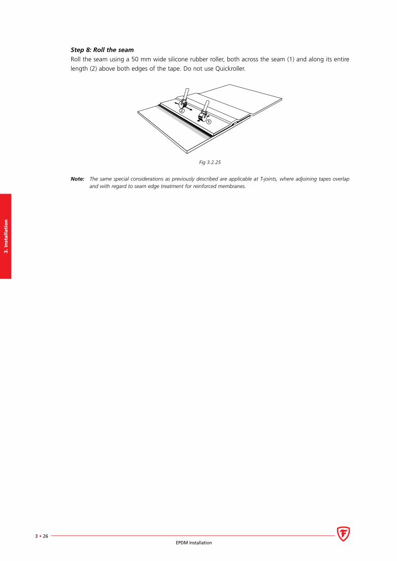
Step 8: Roll the seam
Roll the seam using a 50 mm wide silicone rubber roller, both across the seam (1) and along its entire
length (2) above both edges of the tape. Do not use Quickroller.
Fig 3.2.25
Note: The same special considerations as previously described are applicable at T-joints, where adjoining tapes overlap and with regard to seam edge treatment for reinforced membranes.
3. In
stalla
tion
3 • 27EPDM Installation
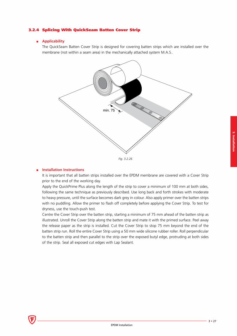
3.2.4 Splicing With QuickSeam Batten Cover Strip
Applicability
The QuickSeam Batten Cover Strip is designed for covering batten strips which are installed over the
membrane (not within a seam area) in the mechanically attached system M.A.S..
min. 75
Fig. 3.2.26
Installation Instructions
It is important that all batten strips installed over the EPDM membrane are covered with a Cover Strip
prior to the end of the working day.
Apply the QuickPrime Plus along the length of the strip to cover a minimum of 100 mm at both sides,
following the same technique as previously described. Use long back and forth strokes with moderate
to heavy pressure, until the surface becomes dark grey in colour. Also apply primer over the batten strips
with no puddling. Allow the primer to flash off completely before applying the Cover Strip. To test for
dryness, use the touch-push test.
Centre the Cover Strip over the batten strip, starting a minimum of 75 mm ahead of the batten strip as
illustrated. Unroll the Cover Strip along the batten strip and mate it with the primed surface. Peel away
the release paper as the strip is installed. Cut the Cover Strip to stop 75 mm beyond the end of the
batten strip run. Roll the entire Cover Strip using a 50 mm wide silicone rubber roller. Roll perpendicular
to the batten strip and then parallel to the strip over the exposed butyl edge, protruding at both sides
of the strip. Seal all exposed cut edges with Lap Sealant.
3.
Inst
all
ati
on
3 • 28EPDM Installation
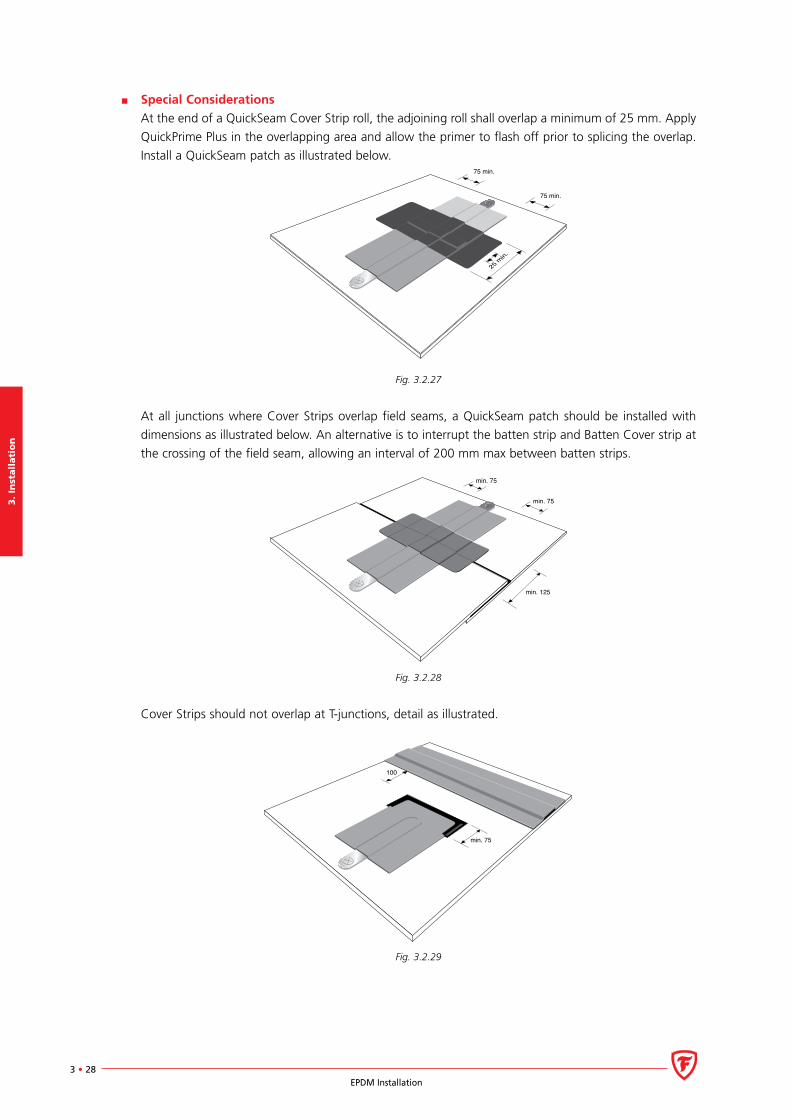
Special Considerations
At the end of a QuickSeam Cover Strip roll, the adjoining roll shall overlap a minimum of 25 mm. Apply
QuickPrime Plus in the overlapping area and allow the primer to flash off prior to splicing the overlap.
Install a QuickSeam patch as illustrated below.
�������
�������
����
���
Fig. 3.2.27
At all junctions where Cover Strips overlap field seams, a QuickSeam patch should be installed with
dimensions as illustrated below. An alternative is to interrupt the batten strip and Batten Cover strip at
the crossing of the field seam, allowing an interval of 200 mm max between batten strips.
min. 125
min. 75
min. 75
Fig. 3.2.28
Cover Strips should not overlap at T-junctions, detail as illustrated.
min. 75
100
Fig. 3.2.29
3. In
stalla
tion
3 • 29EPDM Installation
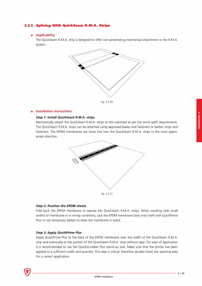
3.2.5 Splicing With QuickSeam R.M.A. Strips
Applicability
The QuickSeam R.M.A. strip is designed to offer non-penetrating mechanical attachment in the R.M.A.
system.
Fig. 3.2.30
Installation Instructions
Step 1: Install QuickSeam R.M.A. strips
Mechanically attach the QuickSeam R.M.A. strips to the substrate as per the wind uplift requirements.
The QuickSeam R.M.A. strips can be attached using approved plates and fasteners or batten strips and
fasteners. The EPDM membranes are loose laid over the QuickSeam R.M.A. strips in the most appro-
priate direction.
76
76100
Fig. 3.2.31
Step 2: Position the EPDM sheets
Fold back the EPDM membrane to expose the QuickSeam R.M.A. strips. When working with small
widths of membrane or in windy conditions, tack the EPDM membrane back onto itself with QuickPrime
Plus or use temporary ballast to keep the membrane in place.
Step 3: Apply QuickPrime Plus
Apply QuickPrime Plus to the back of the EPDM membrane over the width of the QuickSeam R.M.A.
strip and eventually to the portion of the QuickSeam R.M.A. strip without tape. For ease of application
it is recommended to use the QuickScrubber Plus stand-up tool. Make sure that the primer has been
applied to a sufficient width and quantity. This step is critical; therefore double-check the seaming area
for a correct application.
3.
Inst
all
ati
on
3 • 30EPDM Installation
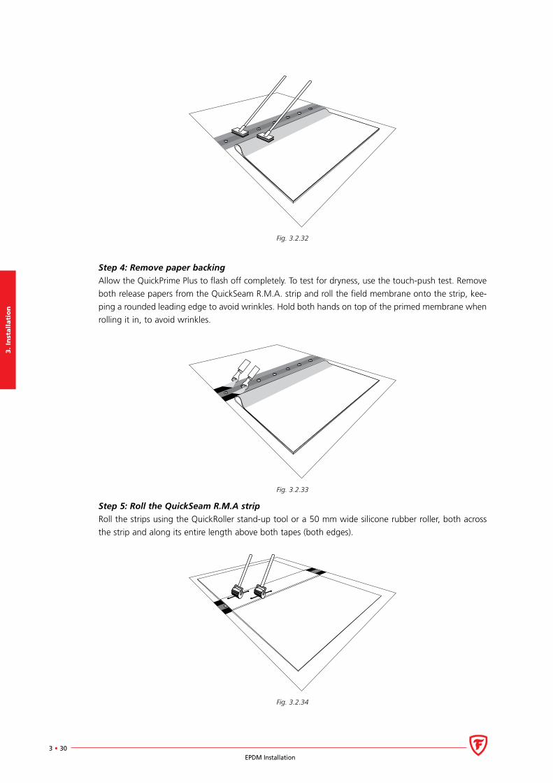
Fig. 3.2.32
Step 4: Remove paper backing
Allow the QuickPrime Plus to flash off completely. To test for dryness, use the touch-push test. Remove
both release papers from the QuickSeam R.M.A. strip and roll the field membrane onto the strip, kee-
ping a rounded leading edge to avoid wrinkles. Hold both hands on top of the primed membrane when
rolling it in, to avoid wrinkles.
Fig. 3.2.33
Step 5: Roll the QuickSeam R.M.A strip
Roll the strips using the QuickRoller stand-up tool or a 50 mm wide silicone rubber roller, both across
the strip and along its entire length above both tapes (both edges).
Fig. 3.2.34
3. In
stalla
tion
3 • 31EPDM Installation
3.2.6 Splicing With Splice Adhesive
Applicability
Experience has learned that QuickSeam details are far more reliable, quick and cost-effective than
Splice Adhesive details. Therefore the QuickSeam solution should always be the method of choice for
any seaming or detailing application. If for some specific reason a QuickSeam solution is not available,
Splice Adhesive alternatives could be used to splice together EPDM with EPDM or regular FormFlash
with EPDM at details if the following installation instructions have been met.
Installation Instructions
EPDM to EPDM and/or FormFlash to EPDM overlaps should always have a minimum width of
100 mm of adhesive seam.
Remove excess of dust, dirt and other contaminants from the EPDM membrane by brooming or
wiping. If necessary, scrub the splice area with soapy water and rinse with clean water.
Use clean cotton rags to clean the mating surfaces thoroughly with Splice Wash in a circular motion
forward; allow to dry. Adequate cleaning has been achieved when the surface is dark grey in colour
and no streaking is evident. Cotton rags must be replaced with clean ones as they become dirty.
FormFlash material is clean and not dusted and does not need to be pre-cleaned.
Apply the Splice Adhesive using a 100 mm wide by 12 mm thick solvent resistant brush in an even,
smooth coat. Use long back and forth strokes, so that brush marks bleed out, leaving a smooth,
glossy adhesive surface. Apply the Splice Adhesive to both mating surfaces at about the same time
to allow approximately equal flash off times. Avoid puddling and do not overwork the adhesive. Use
of paint rollers is not allowed as application rates are uncertain. Where other seams (field or factory)
cross a field seam, use one short back stroke perpendicular to the seam to leave extra adhesive at
the step off.
Allow the adhesive to flash off completely, use the touch-push test to check: touch the adhesive
surface in the middle of the seam with a clean, dry finger. If no adhesive “strings up” or transfers
to the finger, the adhesive is ready for the push test. Push sideways on the adhesive. The adhesive
film should not move. The adhesive can skin over giving the false impression that it is dry. The base
may still be wet, allowing the surface to slide.
Close the seam by mating both coated surfaces. Roll the assembled seam with a 50 mm wide sili-
cone rubber roller using positive pressure. Roll toward the outer edge of the seam, then along its
entire length above the edge. The pressure will strengthen the seam.
Wait a minimum of 4 hours before sealing the exposed edge with Lap Sealant, to enable the solvents
of the adhesive to flash off. If Lap Sealant is applied too soon, the additional solvents of the sealant
may swell the sheet putting additional stresses on the freshly installed seam. The edge of the seam
should be sealed either before the end of the working day, if inclement weather is threatening or
within 24 hours. Clean the edge of the seam where the Lap Sealant is to be applied and apply a
25 mm bead of Lap Sealant, centred above the edge of the seam (coverage rate 6 lm per tube).
Feather the Lap Sealant over the edge using the tool provided or install the Lap Sealant directly using
the preformed nozzle.
Notes:
Every detail in the following chapters specified with QuickSeam FormFlash or QuickSeam Flashing
materials can be alternatively executed using regular FormFlash and Splice Adhesive provided the
above mentioned instructions are followed and the minimum overlap for adhesive seams of 100 mm
is respected.
Regular FormFlash should obligatory be applied using Splice Adhesive. QuickPrime Plus is not suf-
ficient.
3.
Inst
all
ati
on
3 • 32EPDM Installation
3.3 Base Tie-in
3.3.1 Base Tie-in General
In order to account for structural movement of the substrate, stresses inherent in the handling and
production of elastomeric sheets and thermal variations, the EPDM membrane should be mechanically
attached at all locations where the membrane ends or passes through an angle change greater than
15%, such as roof edges, curbs, interior walls, around roof penetrations, etc.
If the securement is inadequate to resist these stresses, the membrane may tear or pull away from the
termination and allow water to enter the building.
For situations where the installation of a base tie-in detail is required but not feasible, consult Firestone’s
Technical Department for advice.
There are two methods of membrane securement at the base tie-in, either the installation of a
QuickSeam Reinforced Perimeter Fastening Strip with batten strips or seam plates beneath the field
membrane or the installation of batten strips directly over the field membrane.
For the following reasons, Firestone recommends the use of a QuickSeam Reinforced Perimeter
Fastening Strip wherever possible:
Reduced installation costs: the Q.S.R.P. Fastening Strip allows for an economical installation, elimi-
nating the increased labour required when interrupting the field membrane.
Fewer roof seams: the system is a non-penetrating method of roof membrane attachment. Field
seams at perimeter walls and roof curbs can be eliminated.
More adapted to inclement weather conditions: perimeter walls and roof curbs can be temporarily
protected against moisture prior to splicing. The roof is watertight at upstands the first day.
The Firestone QuickSeam Reinforced Perimeter Fastening Strip needs to be installed with appropriate
fasteners at maximum centres of 300 mm.
Firestone recommends the use of metal batten strips. Point attached fastening systems can be used as
an alternative in combination with the QuickSeam Reinforced Perimeter fastening strip. When fixing
directly over non-reinforced EPDM membrane, the use of a batten strip is always required. Point atta-
ched fastening systems can not be used in this situation.
Fasteners should be installed so that the fastener heads are flush to the batten or plate. When battens
are cut, the cut end must be rounded to remove burrs and sharp edges.
Some types of insulation materials such as extruded and expanded polystyrene should not come into
contact with the solvents of QuickPrime Plus. It is recommended to extend the vapour control layer 300
mm at the edge of the roof and cover the insulation prior to installation of the base tie-in detail, in order
to protect the insulation materials.
Refer to the details at the end of this document or consult Firestone’s Technical Department for base
tie-in details to adjoining roofing systems.

3. In
stalla
tion
3 • 33EPDM Installation
3.3.2 Base Tie-in With QuickSeam Reinforced Perimeter Fastening Strip
Applicability
The QuickSeam Reinforced Perimeter Fastening Strip is designed to be used in all systems to attach the
field membrane at straight parapets, roof curbs and interior walls. It is the standard detail for perimeter
base tie-ins. The strip should not be used as a mechanically attached perimeter picture frame or as
the separating batten between the adhered perimeter and the central area in mechanically attached
systems.
Installation Instructions
The QuickSeam Reinforced Perimeter Fastening Strip is unrolled along the wall upstand and is either
attached to the flat roof substrate or against the wall. The selection for vertical or horizontal attachment
is related to the ease of application (nature of the substrate, thickness of insulation). A vertical attach-
ment into the upstand is recommended whenever possible. Note that in the following illustrations, the
batten strip on top of the QuickSeam Reinforced Perimeter Fastening Strip can be replaced by plates.
Horizontal attachment of Perimeter Fastening Strip
Position the strip as close as possible in the angle change, making sure that it lays flat without any
wrinkles. The tape with release paper is wound on the outside of the roll. The tape portion of the strip
shall be placed so that the tape side is the farthest from the wall upstand. Allow a maximum gap of
10 mm between the strip and the wall.
300 (max.)
30 (max.)
Fig. 3.3.1
Install the batten strip as illustrated, over the portion of the strip without tape. Avoid buckling and
position the batten and fasteners approx. 30 mm from the edge of the strip. Do not cover any part of
the release paper with the batten strip.
3.
Inst
all
ati
on
3 • 34EPDM Installation
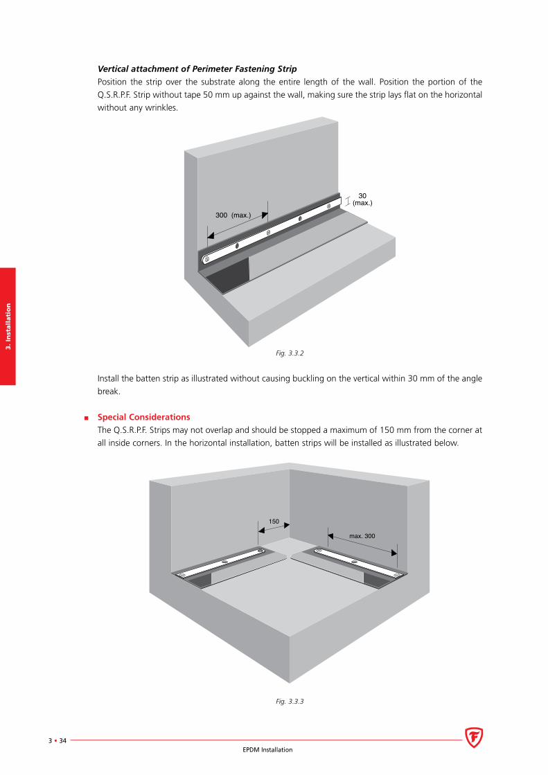
Vertical attachment of Perimeter Fastening Strip
Position the strip over the substrate along the entire length of the wall. Position the portion of the
Q.S.R.P.F. Strip without tape 50 mm up against the wall, making sure the strip lays flat on the horizontal
without any wrinkles.
300 (max.)
30(max.)
Fig. 3.3.2
Install the batten strip as illustrated without causing buckling on the vertical within 30 mm of the angle
break.
Special Considerations
The Q.S.R.P.F. Strips may not overlap and should be stopped a maximum of 150 mm from the corner at
all inside corners. In the horizontal installation, batten strips will be installed as illustrated below.
150
max. 300
Fig. 3.3.3
3. In
stalla
tion
3 • 35EPDM Installation
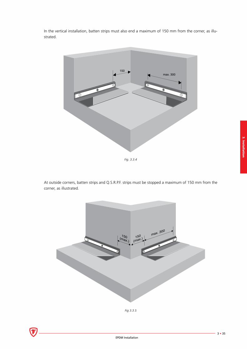
In the vertical installation, batten strips must also end a maximum of 150 mm from the corner, as illu-
strated.
150max. 300
Fig. 3.3.4
At outside corners, batten strips and Q.S.R.P.F. strips must be stopped a maximum of 150 mm from the
corner, as illustrated.
150(max.)150
(max.)max. 300
Fig 3.3.5
3.
Inst
all
ati
on
3 • 36EPDM Installation
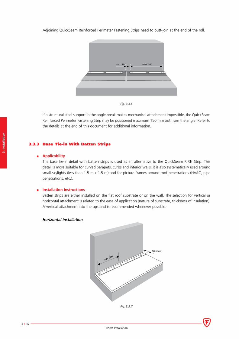
Adjoining QuickSeam Reinforced Perimeter Fastening Strips need to butt-join at the end of the roll.
max. 10 max. 300
Fig. 3.3.6
If a structural steel support in the angle break makes mechanical attachment impossible, the QuickSeam
Reinforced Perimeter Fastening Strip may be positioned maximum 150 mm out from the angle. Refer to
the details at the end of this document for additional information.
3.3.3 Base Tie-in With Batten Strips
Applicability
The base tie-in detail with batten strips is used as an alternative to the QuickSeam R.P.F. Strip. This
detail is more suitable for curved parapets, curbs and interior walls; it is also systematically used around
small skylights (less than 1.5 m x 1.5 m) and for picture frames around roof penetrations (HVAC, pipe
penetrations, etc.).
Installation Instructions
Batten strips are either installed on the flat roof substrate or on the wall. The selection for vertical or
horizontal attachment is related to the ease of application (nature of substrate, thickness of insulation).
A vertical attachment into the upstand is recommended whenever possible.
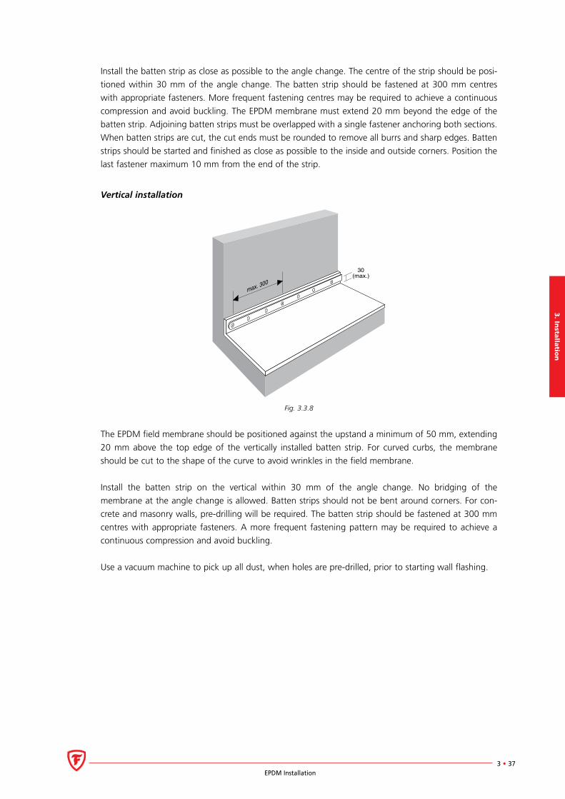
Horizontal installation
30 (max.)
max. 300
Fig. 3.3.7
3. In
stalla
tion
3 • 37EPDM Installation
Install the batten strip as close as possible to the angle change. The centre of the strip should be posi-
tioned within 30 mm of the angle change. The batten strip should be fastened at 300 mm centres
with appropriate fasteners. More frequent fastening centres may be required to achieve a continuous
compression and avoid buckling. The EPDM membrane must extend 20 mm beyond the edge of the
batten strip. Adjoining batten strips must be overlapped with a single fastener anchoring both sections.
When batten strips are cut, the cut ends must be rounded to remove all burrs and sharp edges. Batten
strips should be started and finished as close as possible to the inside and outside corners. Position the
last fastener maximum 10 mm from the end of the strip.
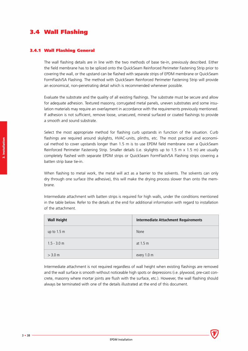
Vertical installation
30(max.)
max. 300
Fig. 3.3.8
The EPDM field membrane should be positioned against the upstand a minimum of 50 mm, extending
20 mm above the top edge of the vertically installed batten strip. For curved curbs, the membrane
should be cut to the shape of the curve to avoid wrinkles in the field membrane.
Install the batten strip on the vertical within 30 mm of the angle change. No bridging of the
membrane at the angle change is allowed. Batten strips should not be bent around corners. For con-
crete and masonry walls, pre-drilling will be required. The batten strip should be fastened at 300 mm
centres with appropriate fasteners. A more frequent fastening pattern may be required to achieve a
continuous compression and avoid buckling.
Use a vacuum machine to pick up all dust, when holes are pre-drilled, prior to starting wall flashing.
3.
Inst
all
ati
on
3 • 38EPDM Installation
3.4 Wall Flashing
3.4.1 Wall Flashing General
The wall flashing details are in line with the two methods of base tie-in, previously described. Either
the field membrane has to be spliced onto the QuickSeam Reinforced Perimeter Fastening Strip prior to
covering the wall, or the upstand can be flashed with separate strips of EPDM membrane or QuickSeam
FormFlash/SA Flashing. The method with QuickSeam Reinforced Perimeter Fastening Strip will provide
an economical, non-penetrating detail which is recommended whenever possible.
Evaluate the substrate and the quality of all existing flashings. The substrate must be secure and allow
for adequate adhesion. Textured masonry, corrugated metal panels, uneven substrates and some insu-
lation materials may require an overlayment in accordance with the requirements previously mentioned.
If adhesion is not sufficient, remove loose, unsecured, mineral surfaced or coated flashings to provide
a smooth and sound substrate.
Select the most appropriate method for flashing curb upstands in function of the situation. Curb
flashings are required around skylights, HVAC-units, plinths, etc. The most practical and economi-
cal method to cover upstands longer than 1.5 m is to use EPDM field membrane over a QuickSeam
Reinforced Perimeter Fastening Strip. Smaller details (i.e. skylights up to 1.5 m x 1.5 m) are usually
completely flashed with separate EPDM strips or QuickSeam FormFlash/SA Flashing strips covering a
batten strip base tie-in.
When flashing to metal work, the metal will act as a barrier to the solvents. The solvents can only
dry through one surface (the adhesive), this will make the drying process slower than onto the mem-
brane.
Intermediate attachment with batten strips is required for high walls, under the conditions mentioned
in the table below. Refer to the details at the end for additional information with regard to installation
of the attachment.
Wall Height Intermediate Attachment Requirements
up to 1.5 m None
1.5 - 3.0 m at 1.5 m
> 3.0 m every 1.0 m
Intermediate attachment is not required regardless of wall height when existing flashings are removed
and the wall surface is smooth without noticeable high spots or depressions (i.e. plywood, pre-cast con-
crete, masonry where mortar joints are flush with the surface, etc.). However, the wall flashing should
always be terminated with one of the details illustrated at the end of this document.
3. In
stalla
tion
3 • 39EPDM Installation
3.4.2 Flashing Over QuickSeam Reinforced Perimeter Fastening Strip
Applicability
This installation method is used at all locations where a QuickSeam Reinforced Perimeter Fastening Strip
is installed.
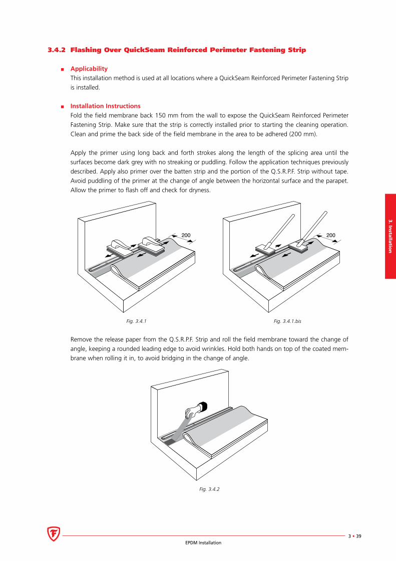
Installation Instructions
Fold the field membrane back 150 mm from the wall to expose the QuickSeam Reinforced Perimeter
Fastening Strip. Make sure that the strip is correctly installed prior to starting the cleaning operation.
Clean and prime the back side of the field membrane in the area to be adhered (200 mm).
Apply the primer using long back and forth strokes along the length of the splicing area until the
surfaces become dark grey with no streaking or puddling. Follow the application techniques previously
described. Apply also primer over the batten strip and the portion of the Q.S.R.P.F. Strip without tape.
Avoid puddling of the primer at the change of angle between the horizontal surface and the parapet.
Allow the primer to flash off and check for dryness.
200 200
Fig. 3.4.1 Fig. 3.4.1.bis
Remove the release paper from the Q.S.R.P.F. Strip and roll the field membrane toward the change of
angle, keeping a rounded leading edge to avoid wrinkles. Hold both hands on top of the coated mem-
brane when rolling it in, to avoid bridging in the change of angle.
Fig. 3.4.2
3.
Inst
all
ati
on
3 • 40EPDM Installation
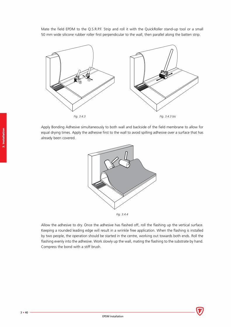
Mate the field EPDM to the Q.S.R.P.F. Strip and roll it with the QuickRoller stand-up tool or a small
50 mm wide silicone rubber roller first perpendicular to the wall, then parallel along the batten strip.
Fig. 3.4.3 Fig. 3.4.3 bis
Apply Bonding Adhesive simultaneously to both wall and backside of the field membrane to allow for
equal drying times. Apply the adhesive first to the wall to avoid spilling adhesive over a surface that has
already been covered.
Fig. 3.4.4
Allow the adhesive to dry. Once the adhesive has flashed off, roll the flashing up the vertical surface.
Keeping a rounded leading edge will result in a wrinkle free application. When the flashing is installed
by two people, the operation should be started in the centre, working out towards both ends. Roll the
flashing evenly into the adhesive. Work slowly up the wall, mating the flashing to the substrate by hand.
Compress the bond with a stiff brush.
3. In
stalla
tion
3 • 41EPDM Installation
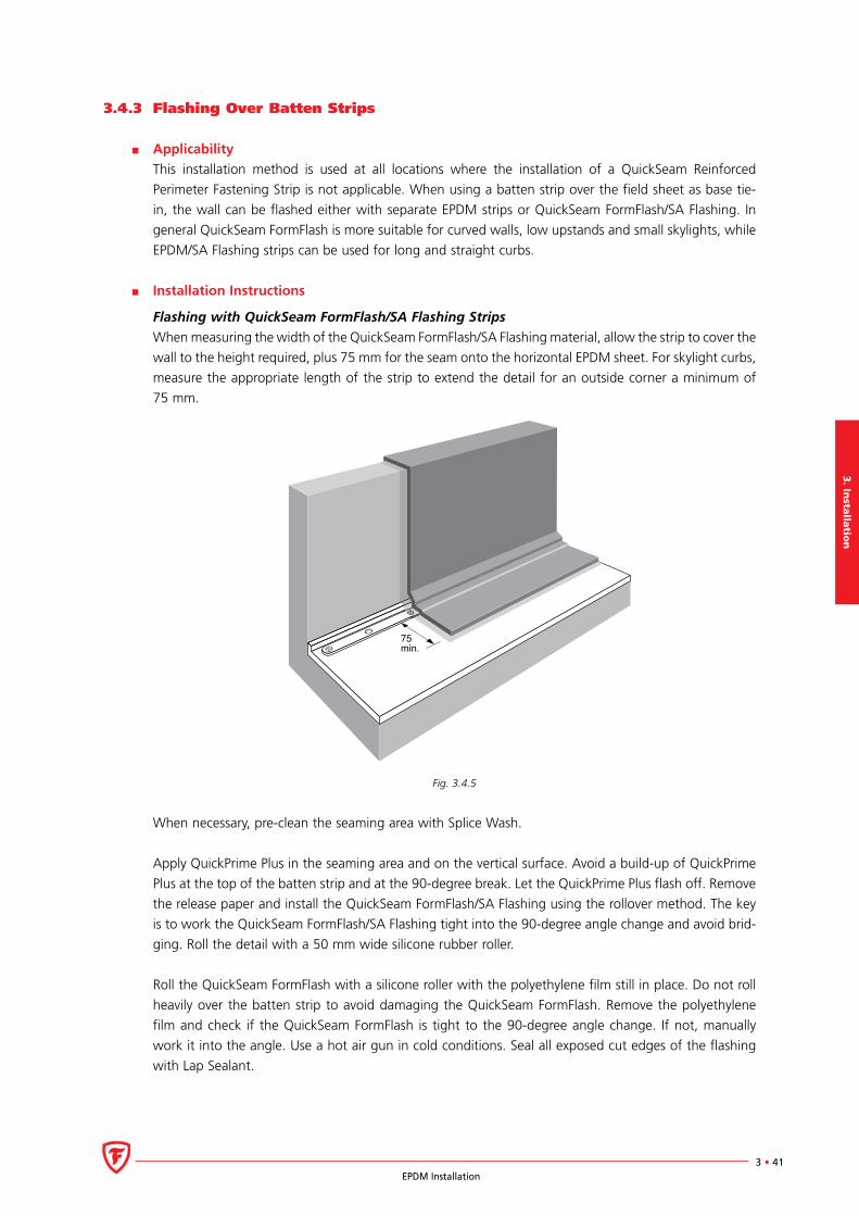
3.4.3 Flashing Over Batten Strips
Applicability
This installation method is used at all locations where the installation of a QuickSeam Reinforced
Perimeter Fastening Strip is not applicable. When using a batten strip over the field sheet as base tie-
in, the wall can be flashed either with separate EPDM strips or QuickSeam FormFlash/SA Flashing. In
general QuickSeam FormFlash is more suitable for curved walls, low upstands and small skylights, while
EPDM/SA Flashing strips can be used for long and straight curbs.
Installation Instructions
Flashing with QuickSeam FormFlash/SA Flashing Strips
When measuring the width of the QuickSeam FormFlash/SA Flashing material, allow the strip to cover the
wall to the height required, plus 75 mm for the seam onto the horizontal EPDM sheet. For skylight curbs,
measure the appropriate length of the strip to extend the detail for an outside corner a minimum of
75 mm.
75min.
Fig. 3.4.5
When necessary, pre-clean the seaming area with Splice Wash.
Apply QuickPrime Plus in the seaming area and on the vertical surface. Avoid a build-up of QuickPrime
Plus at the top of the batten strip and at the 90-degree break. Let the QuickPrime Plus flash off. Remove
the release paper and install the QuickSeam FormFlash/SA Flashing using the rollover method. The key
is to work the QuickSeam FormFlash/SA Flashing tight into the 90-degree angle change and avoid brid-
ging. Roll the detail with a 50 mm wide silicone rubber roller.
Roll the QuickSeam FormFlash with a silicone roller with the polyethylene film still in place. Do not roll
heavily over the batten strip to avoid damaging the QuickSeam FormFlash. Remove the polyethylene
film and check if the QuickSeam FormFlash is tight to the 90-degree angle change. If not, manually
work it into the angle. Use a hot air gun in cold conditions. Seal all exposed cut edges of the flashing
with Lap Sealant.

3.
Inst
all
ati
on
3 • 42EPDM Installation
Flashing with EPDM Membrane Strips
76
Fig. 3.4.6
When measuring the width of the EPDM material, allow the EPDM strip to cover the wall to the height
required, plus 100 mm for the seam onto the horizontal EPDM sheet. The longest pieces practical can
be used to flash high walls to the specified height. Selecting the correct cut for EPDM strips is a time
saver. Factory seams should preferably run parallel to the flashing seam. This will serve as a stabilizer of
the flashing to avoid wrinkles.
Position the EPDM strip 150 mm from the angle break along the wall to be flashed. Clean and prime
the field membrane and the EPDM strip in the splice area over a width of 150 mm with QuickPrime Plus.
Avoid a build-up of primer over the batten strip and at the 90-degree angle break. Allow the QuickPrime
Plus to dry completely. For larger upstands it might be more appropriate to apply the QuickPrime Plus
to the EPDM flashing piece only after the strip has been adhered to the wall.
Install a 76 mm (3”) wide Splice Tape on the field membrane. Position the tape as close as possible to
the angle brake on the horizontal surface. The tape may not cover the batten strip or turn up against
the vertical upstand.
Apply Bonding Adhesive to the remaining area of the EPDM strip and to the wall. Roll the EPDM flashing
into the wall, keeping a rounded leading edge. Mate the flashing by hand and broom with a stiff brush.
Trim the horizontal overlap of the flashing EPDM strip so that 10 mm of the release paper is exposed.
Remove the release paper from the tape and mate the EPDM strip to the tape. Roll the horizontal base
of the EPDM strip with a silicone roller, first perpendicular to the direction of the seam and then along
its entire length.
3. In
stalla
tion
3 • 43EPDM Installation
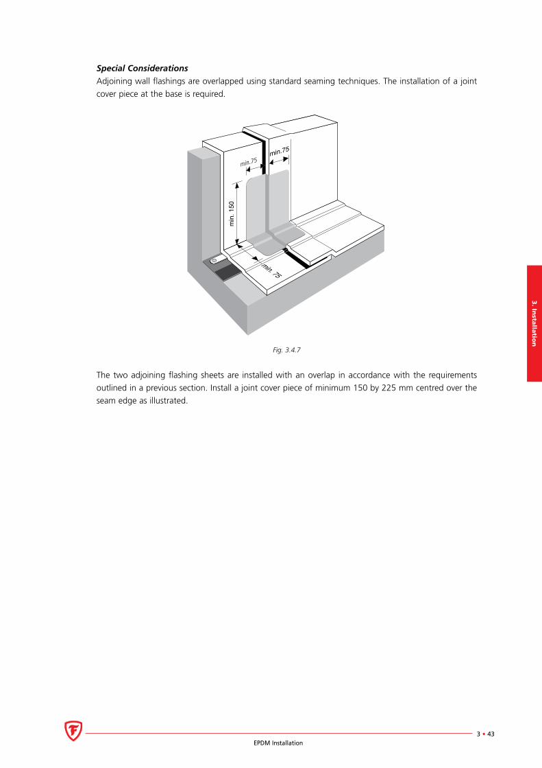
Special Considerations
Adjoining wall flashings are overlapped using standard seaming techniques. The installation of a joint
cover piece at the base is required.
min. 75
min
. 150
min.75
min.75
Fig. 3.4.7
The two adjoining flashing sheets are installed with an overlap in accordance with the requirements
outlined in a previous section. Install a joint cover piece of minimum 150 by 225 mm centred over the
seam edge as illustrated.

3.
Inst
all
ati
on
3 • 44EPDM Installation
3.5 Corners
3.5.1 Inside Corner
Folded Inside Corner
Applicability
At inside corners, the EPDM membrane can be folded into a pig-ear and adhered to the upstand as
illustrated below. This offers a non-penetrating, watertight detail that can be applied on any roof. Note
however that this detail becomes more difficult to execute and less esthetic on higher upstands.
Installation Instructions
The wall flashing is fully adhered to the upstand with the techniques previously described. Work the
EPDM membrane tightly into the angle change and continue up against the upstand.
Fig 3.5.1
Continue the flashing up against the other wall, allowing the membrane to form an internal pig-ear as
illustrated. Close the pig-ear and work from the base to remove all entrapped air.
Fig. 3.5.2
3. In
stalla
tion
3 • 45EPDM Installation
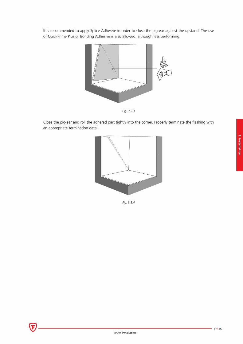
It is recommended to apply Splice Adhesive in order to close the pig-ear against the upstand. The use
of QuickPrime Plus or Bonding Adhesive is also allowed, although less performing.
Fig. 3.5.3
Close the pig-ear and roll the adhered part tightly into the corner. Properly terminate the flashing with
an appropriate termination detail.
Fig. 3.5.4

3.
Inst
all
ati
on
3 • 46EPDM Installation
Inside Corner using 229 mm (9”) QuickSeam FormFlash
Applicability
When flashing higher upstands, the EPDM membrane is cut at the corners so that a vertical seam can
be made at the angle change. The vertical seam is completed with 76 mm (3”) QuickSeam Splice Tape
in accordance with general seaming techniques.
An alternative is to cut the membrane completely away to create a butt joint. In this case, the flashing
techniques remain the same, only the length of the first flashing piece needs to be sufficient to cover
the base overlap with the EPDM membrane (100 mm), the parapet height, plus 100 mm over the top
of the parapet.
Installation Instructions
The inside corner details is a two step process using two identical pieces of QuickSeam FormFlash to
cover the pinhole in the corner. Apply QuickPrime Plus on the membrane, to an area covering 150 mm
out from the pinhole on the horizontal and 250 mm on the vertical surface.
150150
250
Fig. 3.5.5
Both pieces of QuickSeam FormFlash are 229 mm wide and 300 mm long. Make sure to round all cor-
ners of the cut QuickSeam FormFlash pieces. Allow the QuickPrime Plus to flash off completely before
mating the QuickSeam FormFlash.
Fold the first QuickSeam FormFlash piece back onto itself lengthwise, making sure the fold is approxi-
mately 10 mm offset from the center of the piece. Fold back a square base on the smaller half and
remove the release paper.
Position the folded base on the horizontal surface, 10 mm out from the upstand, as illustrated. Work
the flashing piece tightly into the angle change and continue up against the upstand opposite to the
vertical seam.
Fig. 3.5.6 Fig. 3.5.7
3. In
stalla
tion
3 • 47EPDM Installation
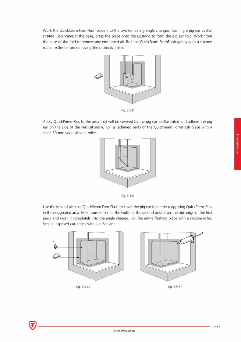
Work the QuickSeam FormFlash piece into the two remaining angle changes, forming a pig ear as illu-
strated. Beginning at the base, press the piece onto the upstand to form the pig ear fold. Work from
the base of the fold to remove any entrapped air. Roll the QuickSeam FormFlash gently with a silicone
rubber roller before removing the protective film.
Fig. 3.5.8
Apply QuickPrime Plus to the area that will be covered by the pig ear as illustrated and adhere the pig
ear on the side of the vertical seam. Roll all adhered parts of the QuickSeam FormFlash piece with a
small 50 mm wide silicone roller.
Fig. 3.5.9
Use the second piece of QuickSeam FormFlash to cover the pig ear fold after reapplying QuickPrime Plus
in the designated area. Make sure to center the width of the second piece over the side edge of the first
piece and work it completely into the angle change. Roll the entire flashing piece with a silicone roller.
Seal all exposed cut edges with Lap Sealant.
Fig. 3.5.10 Fig. 3.5.11
3.
Inst
all
ati
on
3 • 48EPDM Installation
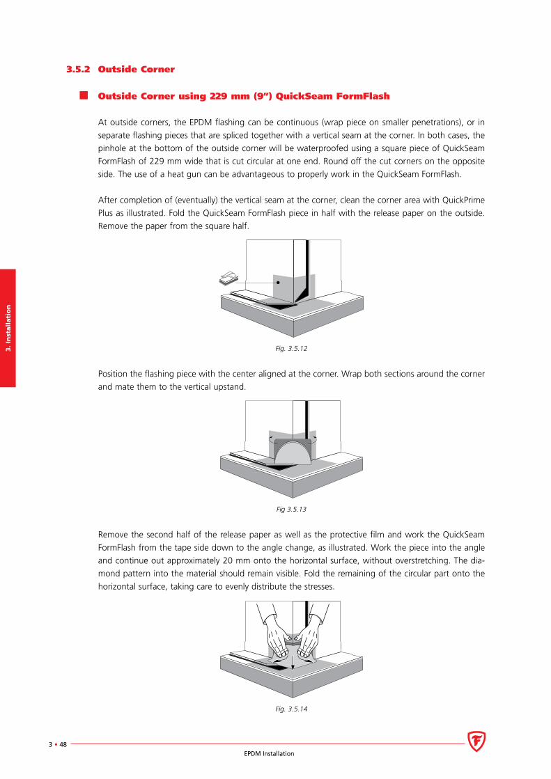
3.5.2 Outside Corner
Outside Corner using 229 mm (9”) QuickSeam FormFlash
At outside corners, the EPDM flashing can be continuous (wrap piece on smaller penetrations), or in
separate flashing pieces that are spliced together with a vertical seam at the corner. In both cases, the
pinhole at the bottom of the outside corner will be waterproofed using a square piece of QuickSeam
FormFlash of 229 mm wide that is cut circular at one end. Round off the cut corners on the opposite
side. The use of a heat gun can be advantageous to properly work in the QuickSeam FormFlash.
After completion of (eventually) the vertical seam at the corner, clean the corner area with QuickPrime
Plus as illustrated. Fold the QuickSeam FormFlash piece in half with the release paper on the outside.
Remove the paper from the square half.
Fig. 3.5.12
Position the flashing piece with the center aligned at the corner. Wrap both sections around the corner
and mate them to the vertical upstand.
Fig 3.5.13
Remove the second half of the release paper as well as the protective film and work the QuickSeam
FormFlash from the tape side down to the angle change, as illustrated. Work the piece into the angle
and continue out approximately 20 mm onto the horizontal surface, without overstretching. The dia-
mond pattern into the material should remain visible. Fold the remaining of the circular part onto the
horizontal surface, taking care to evenly distribute the stresses.
Fig. 3.5.14
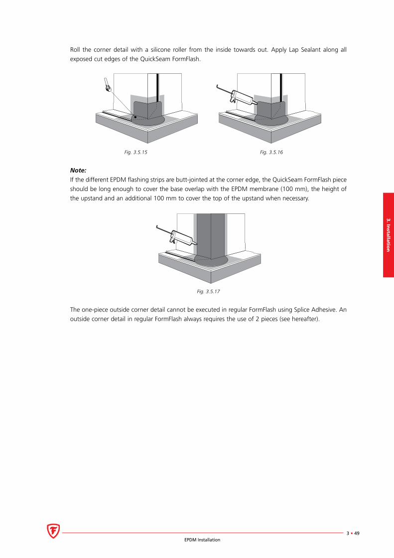
3. In
stalla
tion
3 • 49EPDM Installation
Roll the corner detail with a silicone roller from the inside towards out. Apply Lap Sealant along all
exposed cut edges of the QuickSeam FormFlash.
Fig. 3.5.15 Fig. 3.5.16
Note:
If the different EPDM flashing strips are butt-jointed at the corner edge, the QuickSeam FormFlash piece
should be long enough to cover the base overlap with the EPDM membrane (100 mm), the height of
the upstand and an additional 100 mm to cover the top of the upstand when necessary.
Fig. 3.5.17
The one-piece outside corner detail cannot be executed in regular FormFlash using Splice Adhesive. An
outside corner detail in regular FormFlash always requires the use of 2 pieces (see hereafter).

3.
Inst
all
ati
on
3 • 50EPDM Installation
Alternative Outside Corner Detail
When dressing small roof penetrations (skylights, HVAC units,...), it can be more practical and/or cost-
effective to flash in the upstands completely with QuickSeam FormFlash instead of using EPDM flashing
strips. In this case, the outside corner detail is a two-step process.
Apply QuickPrime Plus to the EPDM membrane and upstand as illustrated.
Fig. 3.5.18 Fig. 3.5.19
Allow the QuickPrime Plus to flash off completely before mating the QuickSeam FormFlash. Install
the first flashing piece with a base overlap of 75 mm and exceeding the corner by 75 mm. Work
the QuickSeam FormFlash into the angle before mating it to the vertical surface. Roll the QuickSeam
FormFlash gently with a 50 mm wide silicone rubber roller while it is still protected by the protective
film. Remove the protective film and work the corner tightly into the 90° angle. In order to complete the
corner wrap, it is recommended to trim off half of the strips of FormFlash exceeding the corner. Apply
heat if necessary. Avoid overheating and overstretching of the QuickSeam FormFlash.
Fig. 3.5.20
Repeat this procedure, starting from the other side to provide an overlap of at least 75 mm at the corner.
Apply QuickPrime Plus on the area to be overlapped, complete the corner detail and seal all exposed cut
edges of the QuickSeam FormFlash with Lap Sealant.
3. In
stalla
tion
3 • 51EPDM Installation
3.6 Pipe Penetrations
3.6.1 Penetrations General
This section provides information with regard to detailing around circular and odd shaped roof pene-
trations.
All penetrations passing through the membrane should be flashed using one of the following techni-
ques:
QuickSeam Pipe Boot or Conduit Flashing.
Field fabricated pipe flashing.
Penetration Pocket.
For re-roofing applications, all existing flashings should be stripped off (i.e. lead , existing roofing mem-
branes, mastic, etc.) prior to installation of the new detail. The flashing seal must be made directly to
the penetration.
All pipes must be anchored to the deck, as loose pipes move and may damage the flashing.
All rubber components should be protected from direct contact with steam or heat sources when the
in-service temperature of the penetration is in excess of 82ºC. In such cases the flashing can be instal-
led directly to an intermediate insulated cool sleeve. Pipe boots and QuickSeam FormFlash require the
installation of a rain collar at the sleeve/pipe junction.
In mechanically attached systems a batten layout is required around each pipe penetration. Refer to the
details at the end of this document for additional information.
All metal edges used at pipe penetrations must have rounded corners.
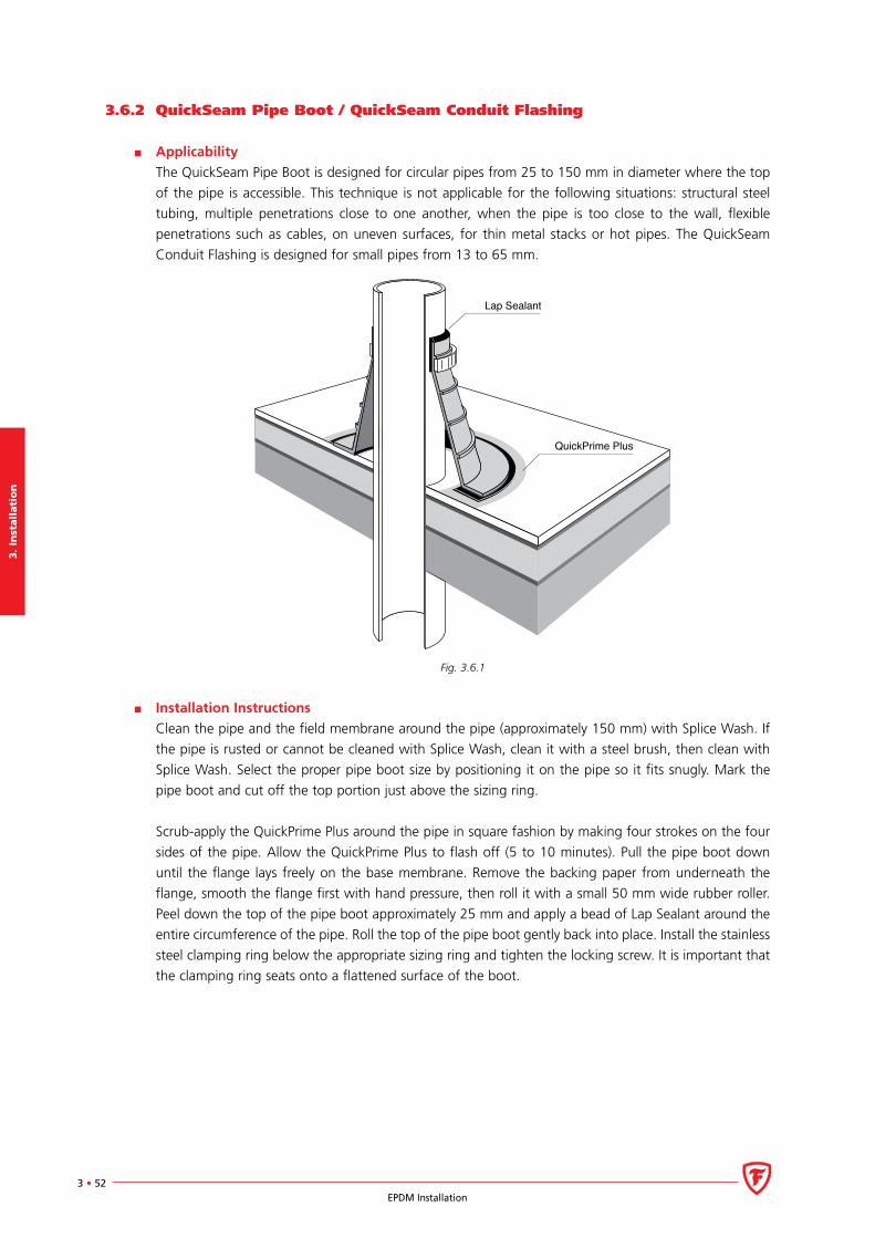
3.
Inst
all
ati
on
3 • 52EPDM Installation
3.6.2 QuickSeam Pipe Boot / QuickSeam Conduit Flashing
Applicability
The QuickSeam Pipe Boot is designed for circular pipes from 25 to 150 mm in diameter where the top
of the pipe is accessible. This technique is not applicable for the following situations: structural steel
tubing, multiple penetrations close to one another, when the pipe is too close to the wall, flexible
penetrations such as cables, on uneven surfaces, for thin metal stacks or hot pipes. The QuickSeam
Conduit Flashing is designed for small pipes from 13 to 65 mm.
Lap Sealant
QuickPrime Plus
Fig. 3.6.1
Installation Instructions
Clean the pipe and the field membrane around the pipe (approximately 150 mm) with Splice Wash. If
the pipe is rusted or cannot be cleaned with Splice Wash, clean it with a steel brush, then clean with
Splice Wash. Select the proper pipe boot size by positioning it on the pipe so it fits snugly. Mark the
pipe boot and cut off the top portion just above the sizing ring.
Scrub-apply the QuickPrime Plus around the pipe in square fashion by making four strokes on the four
sides of the pipe. Allow the QuickPrime Plus to flash off (5 to 10 minutes). Pull the pipe boot down
until the flange lays freely on the base membrane. Remove the backing paper from underneath the
flange, smooth the flange first with hand pressure, then roll it with a small 50 mm wide rubber roller.
Peel down the top of the pipe boot approximately 25 mm and apply a bead of Lap Sealant around the
entire circumference of the pipe. Roll the top of the pipe boot gently back into place. Install the stainless
steel clamping ring below the appropriate sizing ring and tighten the locking screw. It is important that
the clamping ring seats onto a flattened surface of the boot.
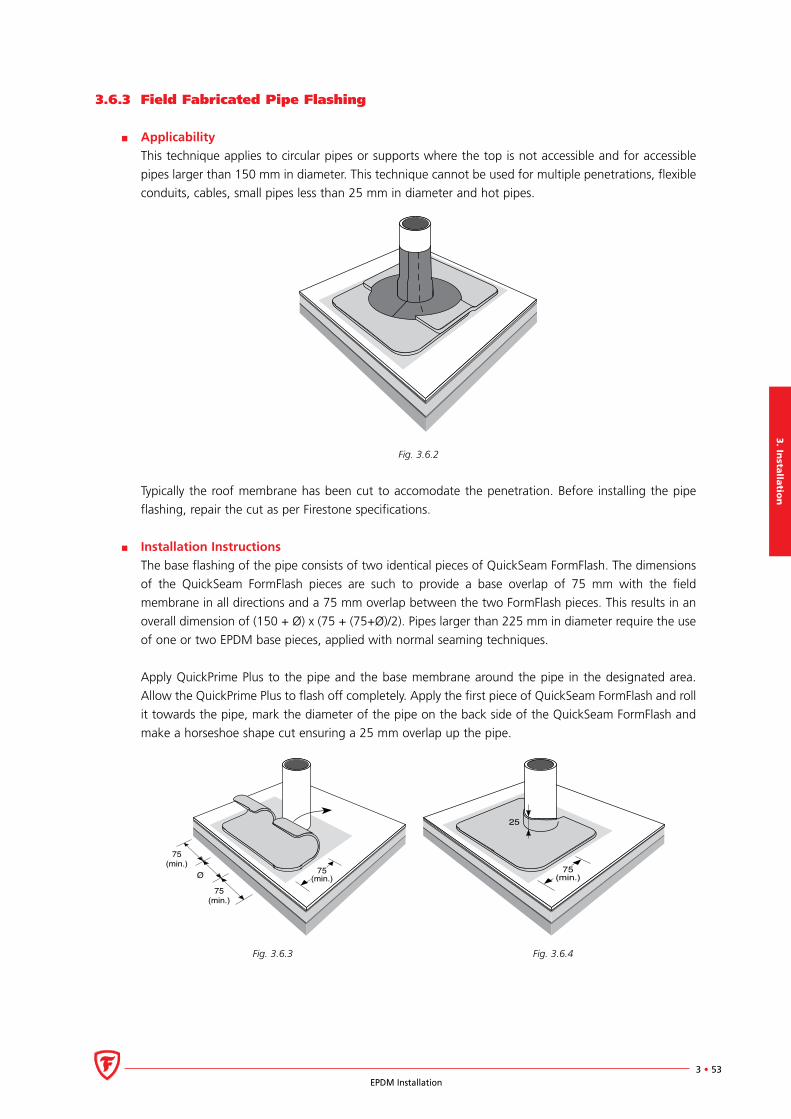
3. In
stalla
tion
3 • 53EPDM Installation
3.6.3 Field Fabricated Pipe Flashing
Applicability
This technique applies to circular pipes or supports where the top is not accessible and for accessible
pipes larger than 150 mm in diameter. This technique cannot be used for multiple penetrations, flexible
conduits, cables, small pipes less than 25 mm in diameter and hot pipes.
Fig. 3.6.2
Typically the roof membrane has been cut to accomodate the penetration. Before installing the pipe
flashing, repair the cut as per Firestone specifications.
Installation Instructions
The base flashing of the pipe consists of two identical pieces of QuickSeam FormFlash. The dimensions
of the QuickSeam FormFlash pieces are such to provide a base overlap of 75 mm with the field
membrane in all directions and a 75 mm overlap between the two FormFlash pieces. This results in an
overall dimension of (150 + Ø) x (75 + (75+Ø)/2). Pipes larger than 225 mm in diameter require the use
of one or two EPDM base pieces, applied with normal seaming techniques.
Apply QuickPrime Plus to the pipe and the base membrane around the pipe in the designated area.
Allow the QuickPrime Plus to flash off completely. Apply the first piece of QuickSeam FormFlash and roll
it towards the pipe, mark the diameter of the pipe on the back side of the QuickSeam FormFlash and
make a horseshoe shape cut ensuring a 25 mm overlap up the pipe.
75(min.)
75(min.)
75(min.)Ø
25
75(min.)
Fig. 3.6.3 Fig. 3.6.4
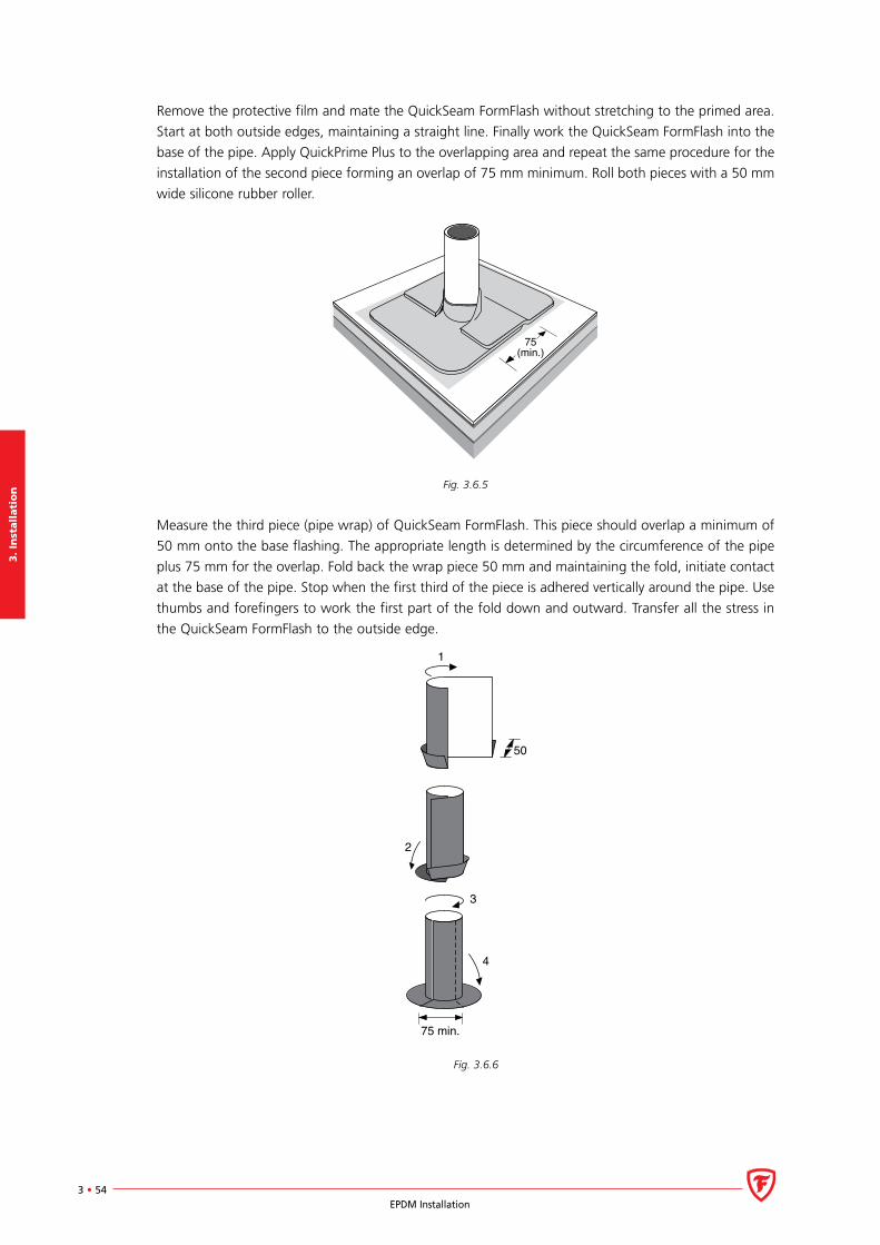
3.
Inst
all
ati
on
3 • 54EPDM Installation
Remove the protective film and mate the QuickSeam FormFlash without stretching to the primed area.
Start at both outside edges, maintaining a straight line. Finally work the QuickSeam FormFlash into the
base of the pipe. Apply QuickPrime Plus to the overlapping area and repeat the same procedure for the
installation of the second piece forming an overlap of 75 mm minimum. Roll both pieces with a 50 mm
wide silicone rubber roller.
75(min.)
Fig. 3.6.5
Measure the third piece (pipe wrap) of QuickSeam FormFlash. This piece should overlap a minimum of
50 mm onto the base flashing. The appropriate length is determined by the circumference of the pipe
plus 75 mm for the overlap. Fold back the wrap piece 50 mm and maintaining the fold, initiate contact
at the base of the pipe. Stop when the first third of the piece is adhered vertically around the pipe. Use
thumbs and forefingers to work the first part of the fold down and outward. Transfer all the stress in
the QuickSeam FormFlash to the outside edge.
75 min.
50
1
2
3
4
Fig. 3.6.6
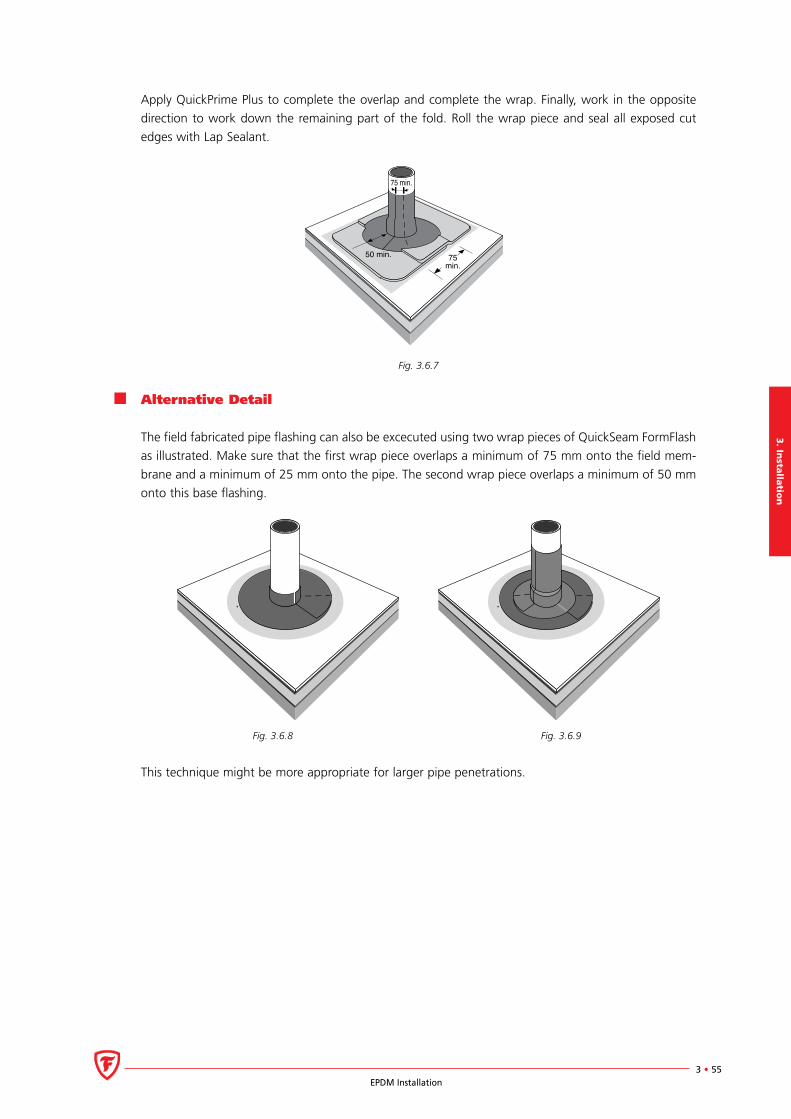
3. In
stalla
tion
3 • 55EPDM Installation
Apply QuickPrime Plus to complete the overlap and complete the wrap. Finally, work in the opposite
direction to work down the remaining part of the fold. Roll the wrap piece and seal all exposed cut
edges with Lap Sealant.
Fig. 3.6.7
Alternative Detail
The field fabricated pipe flashing can also be excecuted using two wrap pieces of QuickSeam FormFlash
as illustrated. Make sure that the first wrap piece overlaps a minimum of 75 mm onto the field mem-
brane and a minimum of 25 mm onto the pipe. The second wrap piece overlaps a minimum of 50 mm
onto this base flashing.
Fig. 3.6.8 Fig. 3.6.9
This technique might be more appropriate for larger pipe penetrations.
75min.
75 min.
50 min.
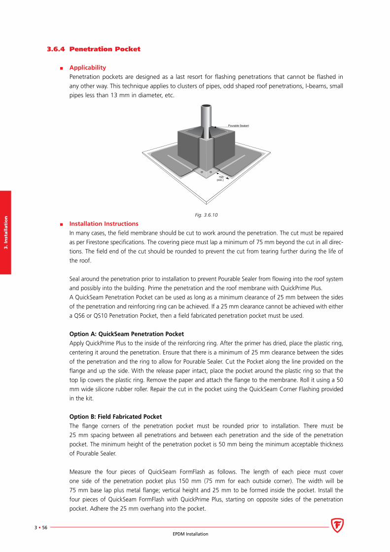
3.
Inst
all
ati
on
3 • 56EPDM Installation
3.6.4 Penetration Pocket
Applicability
Penetration pockets are designed as a last resort for flashing penetrations that cannot be flashed in
any other way. This technique applies to clusters of pipes, odd shaped roof penetrations, I-beams, small
pipes less than 13 mm in diameter, etc.
Pourable Sealant
75�(min.)
Fig. 3.6.10
Installation Instructions
In many cases, the field membrane should be cut to work around the penetration. The cut must be repaired
as per Firestone specifications. The covering piece must lap a minimum of 75 mm beyond the cut in all direc-
tions. The field end of the cut should be rounded to prevent the cut from tearing further during the life of
the roof.
Seal around the penetration prior to installation to prevent Pourable Sealer from flowing into the roof system
and possibly into the building. Prime the penetration and the roof membrane with QuickPrime Plus.
A QuickSeam Penetration Pocket can be used as long as a minimum clearance of 25 mm between the sides
of the penetration and reinforcing ring can be achieved. If a 25 mm clearance cannot be achieved with either
a QS6 or QS10 Penetration Pocket, then a field fabricated penetration pocket must be used.
Option A: QuickSeam Penetration Pocket
Apply QuickPrime Plus to the inside of the reinforcing ring. After the primer has dried, place the plastic ring,
centering it around the penetration. Ensure that there is a minimum of 25 mm clearance between the sides
of the penetration and the ring to allow for Pourable Sealer. Cut the Pocket along the line provided on the
flange and up the side. With the release paper intact, place the pocket around the plastic ring so that the
top lip covers the plastic ring. Remove the paper and attach the flange to the membrane. Roll it using a 50
mm wide silicone rubber roller. Repair the cut in the pocket using the QuickSeam Corner Flashing provided
in the kit.
Option B: Field Fabricated Pocket
The flange corners of the penetration pocket must be rounded prior to installation. There must be
25 mm spacing between all penetrations and between each penetration and the side of the penetration
pocket. The minimum height of the penetration pocket is 50 mm being the minimum acceptable thickness
of Pourable Sealer.
Measure the four pieces of QuickSeam FormFlash as follows. The length of each piece must cover
one side of the penetration pocket plus 150 mm (75 mm for each outside corner). The width will be
75 mm base lap plus metal flange; vertical height and 25 mm to be formed inside the pocket. Install the
four pieces of QuickSeam FormFlash with QuickPrime Plus, starting on opposite sides of the penetration
pocket. Adhere the 25 mm overhang into the pocket.

3. In
stalla
tion
3 • 57EPDM Installation
Refer to the Product Information Sheet for information with regard to storage, mixing and preparation of the
Pourable Sealer material. Use a stick to force the sealant between all penetrations while pouring it into the
penetration pocket. Make sure that the sealant is worked between the pipes. Crown the penetration pocket
by cresting the sealant in the centre and tapering it to the sides. Cool storage temperatures (below 15°C)
may result in a difficult application. Seal all exposed cut edges of the QuickSeam FormFlash with Lap Sealant.
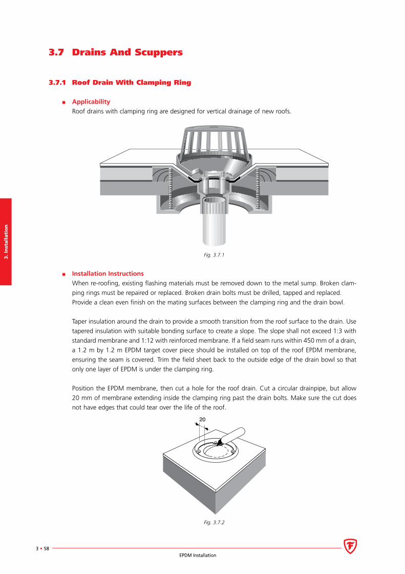
3.
Inst
all
ati
on
3 • 58EPDM Installation
3.7 Drains And Scuppers
3.7.1 Roof Drain With Clamping Ring
Applicability
Roof drains with clamping ring are designed for vertical drainage of new roofs.
Fig. 3.7.1
Installation Instructions
When re-roofing, existing flashing materials must be removed down to the metal sump. Broken clam-
ping rings must be repaired or replaced. Broken drain bolts must be drilled, tapped and replaced.
Provide a clean even finish on the mating surfaces between the clamping ring and the drain bowl.
Taper insulation around the drain to provide a smooth transition from the roof surface to the drain. Use
tapered insulation with suitable bonding surface to create a slope. The slope shall not exceed 1:3 with
standard membrane and 1:12 with reinforced membrane. If a field seam runs within 450 mm of a drain,
a 1.2 m by 1.2 m EPDM target cover piece should be installed on top of the roof EPDM membrane,
ensuring the seam is covered. Trim the field sheet back to the outside edge of the drain bowl so that
only one layer of EPDM is under the clamping ring.
Position the EPDM membrane, then cut a hole for the roof drain. Cut a circular drainpipe, but allow
20 mm of membrane extending inside the clamping ring past the drain bolts. Make sure the cut does
not have edges that could tear over the life of the roof.
20
Fig. 3.7.2
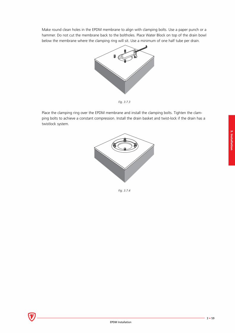
3. In
stalla
tion
3 • 59EPDM Installation
Make round clean holes in the EPDM membrane to align with clamping bolts. Use a paper punch or a
hammer. Do not cut the membrane back to the boltholes. Place Water Block on top of the drain bowl
below the membrane where the clamping ring will sit. Use a minimum of one half tube per drain.
Fig. 3.7.3
Place the clamping ring over the EPDM membrane and install the clamping bolts. Tighten the clam-
ping bolts to achieve a constant compression. Install the drain basket and twist-lock if the drain has a
twistlock system.
Fig. 3.7.4
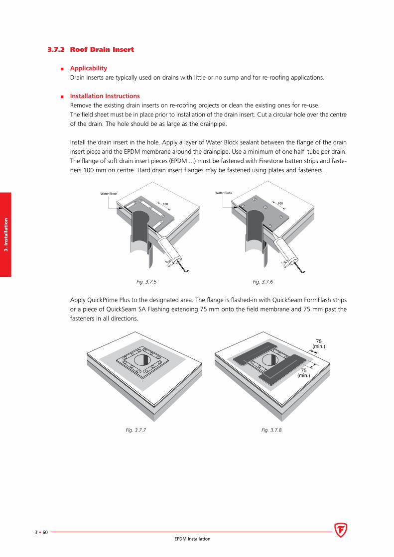
3.
Inst
all
ati
on
3 • 60EPDM Installation
3.7.2 Roof Drain Insert
Applicability
Drain inserts are typically used on drains with little or no sump and for re-roofing applications.
Installation Instructions
Remove the existing drain inserts on re-roofing projects or clean the existing ones for re-use.
The field sheet must be in place prior to installation of the drain insert. Cut a circular hole over the centre
of the drain. The hole should be as large as the drainpipe.
Install the drain insert in the hole. Apply a layer of Water Block sealant between the flange of the drain
insert piece and the EPDM membrane around the drainpipe. Use a minimum of one half tube per drain.
The flange of soft drain insert pieces (EPDM ...) must be fastened with Firestone batten strips and faste-
ners 100 mm on centre. Hard drain insert flanges may be fastened using plates and fasteners.
Water Block
100
Water Block
100
Fig. 3.7.5 Fig. 3.7.6
Apply QuickPrime Plus to the designated area. The flange is flashed-in with QuickSeam FormFlash strips
or a piece of QuickSeam SA Flashing extending 75 mm onto the field membrane and 75 mm past the
fasteners in all directions.
75(min.)
75(min.)
Fig. 3.7.7 Fig. 3.7.8
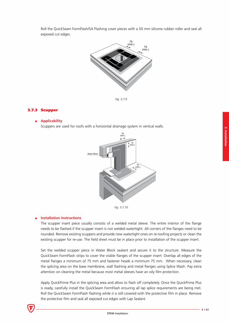
3. In
stalla
tion
3 • 61EPDM Installation
Roll the QuickSeam FormFlash/SA Flashing cover pieces with a 50 mm silicone rubber roller and seal all
exposed cut edges.
75(min.)
75(min.)
Fig. 3.7.9
3.7.3 Scupper
Applicability
Scuppers are used for roofs with a horizontal drainage system in vertical walls.
Water Block
75(min.)
75(min.)
75(min.)
Fig. 3.7.10
Installation Instructions
The scupper insert piece usually consists of a welded metal sleeve. The entire interior of the flange
needs to be flashed if the scupper insert is not welded watertight. All corners of the flanges need to be
rounded. Remove existing scuppers and provide new watertight ones on re-roofing projects or clean the
existing scupper for re-use. The field sheet must be in place prior to installation of the scupper insert.
Set the welded scupper piece in Water Block sealant and secure it to the structure. Measure the
QuickSeam FormFlash strips to cover the visible flanges of the scupper insert. Overlap all edges of the
metal flanges a minimum of 75 mm and fastener heads a minimum 75 mm. When necessary, clean
the splicing area on the base membrane, wall flashing and metal flanges using Splice Wash. Pay extra
attention on cleaning the metal because most metal sleeves have an oily film protection.
Apply QuickPrime Plus in the splicing area and allow to flash off completely. Once the QuickPrime Plus
is ready, carefully install the QuickSeam FormFlash ensuring all lap splice requirements are being met.
Roll the QuickSeam FormFlash flashing while it is still covered with the protective film in place. Remove
the protective film and seal all exposed cut edges with Lap Sealant.
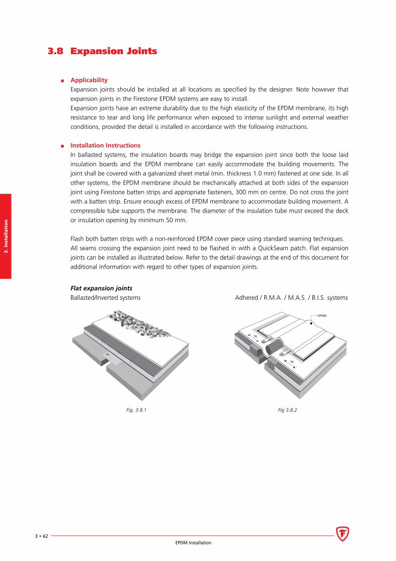
3.
Inst
all
ati
on
3 • 62EPDM Installation
3.8 Expansion Joints
Applicability
Expansion joints should be installed at all locations as specified by the designer. Note however that
expansion joints in the Firestone EPDM systems are easy to install.
Expansion joints have an extreme durability due to the high elasticity of the EPDM membrane, its high
resistance to tear and long life performance when exposed to intense sunlight and external weather
conditions, provided the detail is installed in accordance with the following instructions.
Installation Instructions
In ballasted systems, the insulation boards may bridge the expansion joint since both the loose laid
insulation boards and the EPDM membrane can easily accommodate the building movements. The
joint shall be covered with a galvanized sheet metal (min. thickness 1.0 mm) fastened at one side. In all
other systems, the EPDM membrane should be mechanically attached at both sides of the expansion
joint using Firestone batten strips and appropriate fasteners, 300 mm on centre. Do not cross the joint
with a batten strip. Ensure enough excess of EPDM membrane to accommodate building movement. A
compressible tube supports the membrane. The diameter of the insulation tube must exceed the deck
or insulation opening by minimum 50 mm.
Flash both batten strips with a non-reinforced EPDM cover piece using standard seaming techniques.
All seams crossing the expansion joint need to be flashed in with a QuickSeam patch. Flat expansion
joints can be installed as illustrated below. Refer to the detail drawings at the end of this document for
additional information with regard to other types of expansion joints.
Flat expansion joints
Ballasted/Inverted systems Adhered / R.M.A. / M.A.S. / B.I.S. systems
76
76
EPDM
Fig. 3.8.1 Fig 3.8.2
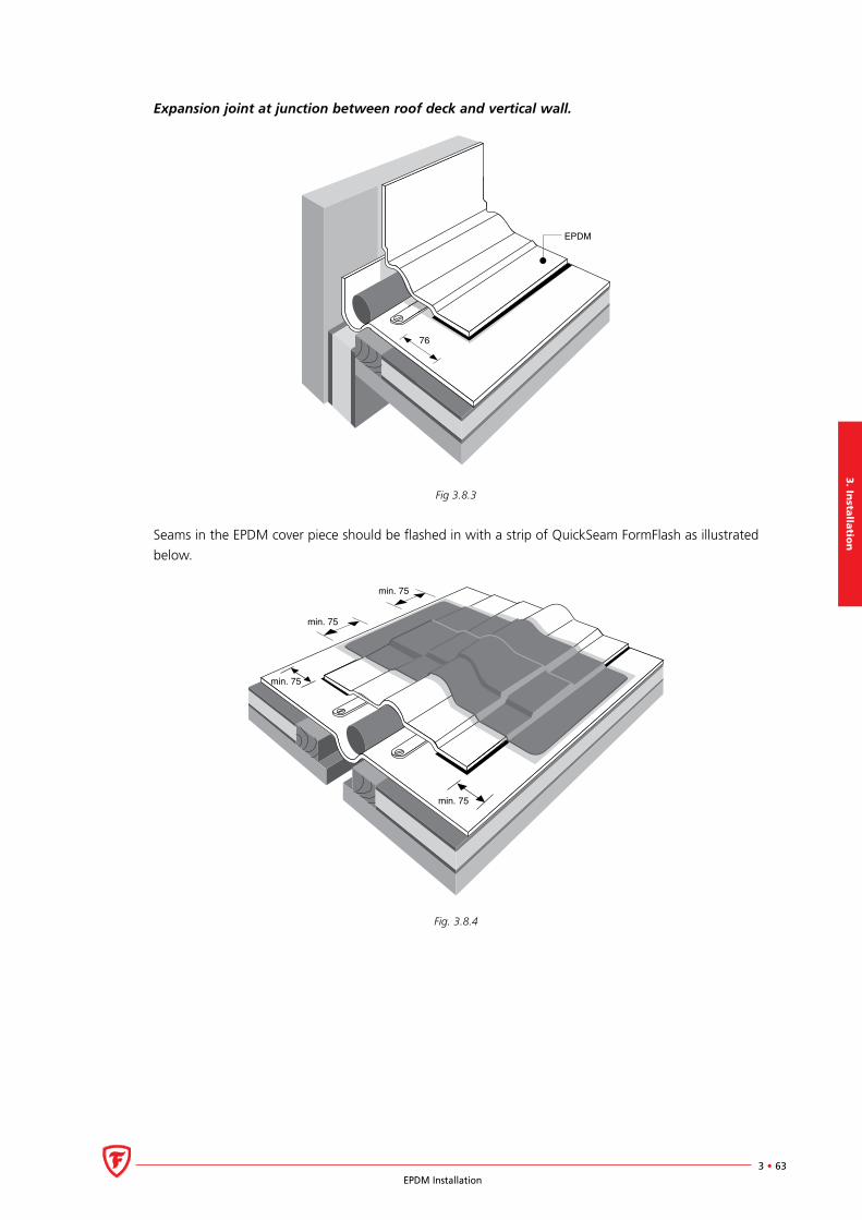
3. In
stalla
tion
3 • 63EPDM Installation
Expansion joint at junction between roof deck and vertical wall.
76
EPDM
Fig 3.8.3
Seams in the EPDM cover piece should be flashed in with a strip of QuickSeam FormFlash as illustrated
below.
min. 75
min. 75
min. 75
min. 75
Fig. 3.8.4
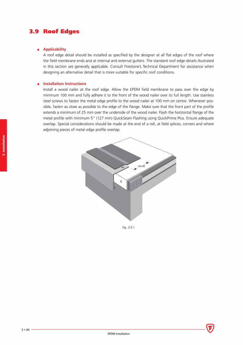
3.
Inst
all
ati
on
3 • 64EPDM Installation
3.9 Roof Edges
Applicability
A roof edge detail should be installed as specified by the designer at all flat edges of the roof where
the field membrane ends and at internal and external gutters. The standard roof edge details illustrated
in this section are generally applicable. Consult Firestone’s Technical Department for assistance when
designing an alternative detail that is more suitable for specific roof conditions.
Installation Instructions
Install a wood nailer at the roof edge. Allow the EPDM field membrane to pass over the edge by
minimum 100 mm and fully adhere it to the front of the wood nailer over its full length. Use stainless
steel screws to fasten the metal edge profile to the wood nailer at 100 mm on centre. Whenever pos-
sible, fasten as close as possible to the edge of the flange. Make sure that the front part of the profile
extends a minimum of 25 mm over the underside of the wood nailer. Flash the horizontal flange of the
metal profile with minimum 5” (127 mm) QuickSeam Flashing using QuickPrime Plus. Ensure adequate
overlap. Special considerations should be made at the end of a roll, at field splices, corners and where
adjoining pieces of metal edge profile overlap.
min.50
Fig. 3.9.1
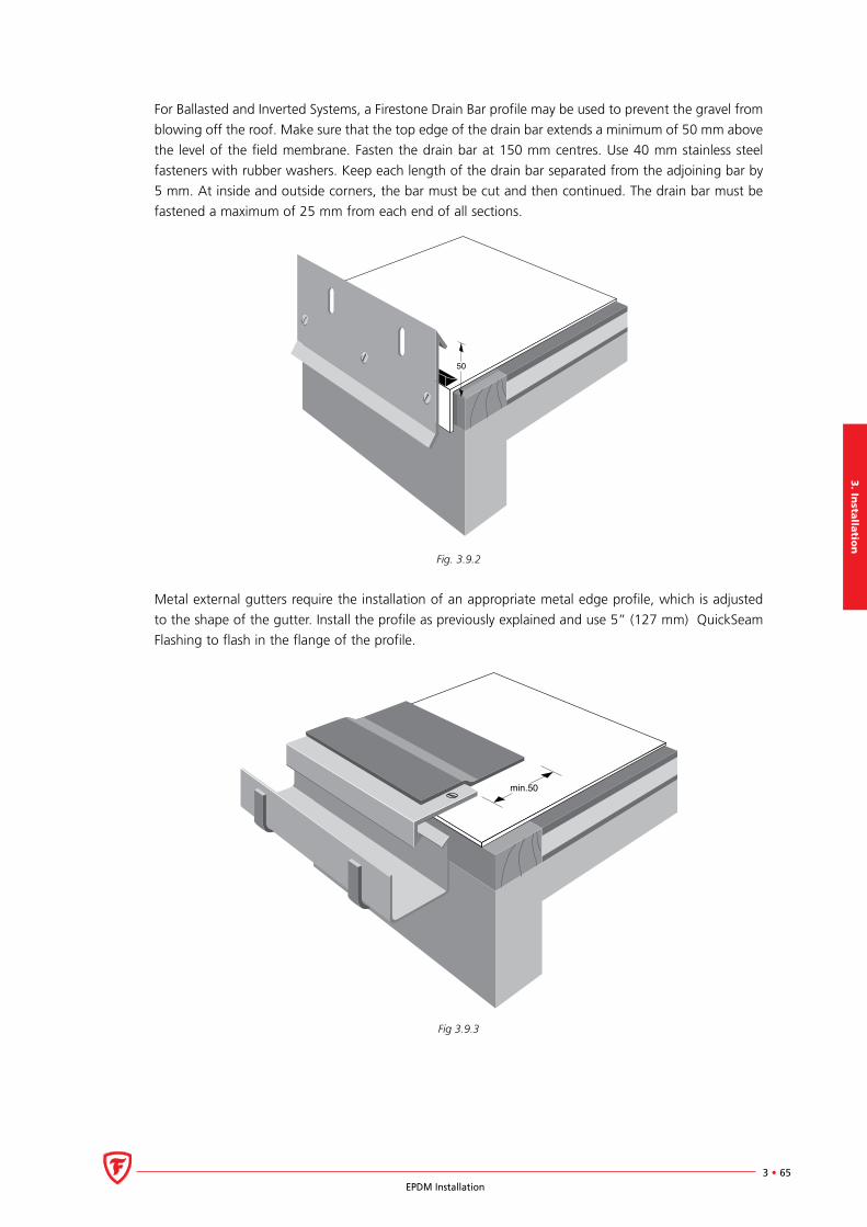
3. In
stalla
tion
3 • 65EPDM Installation
For Ballasted and Inverted Systems, a Firestone Drain Bar profile may be used to prevent the gravel from
blowing off the roof. Make sure that the top edge of the drain bar extends a minimum of 50 mm above
the level of the field membrane. Fasten the drain bar at 150 mm centres. Use 40 mm stainless steel
fasteners with rubber washers. Keep each length of the drain bar separated from the adjoining bar by
5 mm. At inside and outside corners, the bar must be cut and then continued. The drain bar must be
fastened a maximum of 25 mm from each end of all sections.
50
Fig. 3.9.2
Metal external gutters require the installation of an appropriate metal edge profile, which is adjusted
to the shape of the gutter. Install the profile as previously explained and use 5” (127 mm) QuickSeam
Flashing to flash in the flange of the profile.
min.50
Fig 3.9.3
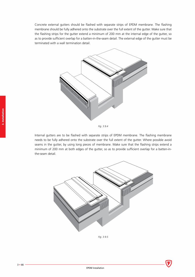
3.
Inst
all
ati
on
3 • 66EPDM Installation
Concrete external gutters should be flashed with separate strips of EPDM membrane. The flashing
membrane should be fully adhered onto the substrate over the full extent of the gutter. Make sure that
the flashing strips for the gutter extend a minimum of 200 mm at the internal edge of the gutter, so
as to provide sufficient overlap for a batten-in-the-seam detail. The external edge of the gutter must be
terminated with a wall termination detail.
Fig. 3.9.4
Internal gutters are to be flashed with separate strips of EPDM membrane. The flashing membrane
needs to be fully adhered onto the substrate over the full extent of the gutter. Where possible avoid
seams in the gutter, by using long pieces of membrane. Make sure that the flashing strips extend a
minimum of 200 mm at both edges of the gutter, so as to provide sufficient overlap for a batten-in-
the-seam detail.
Fig. 3.9.5
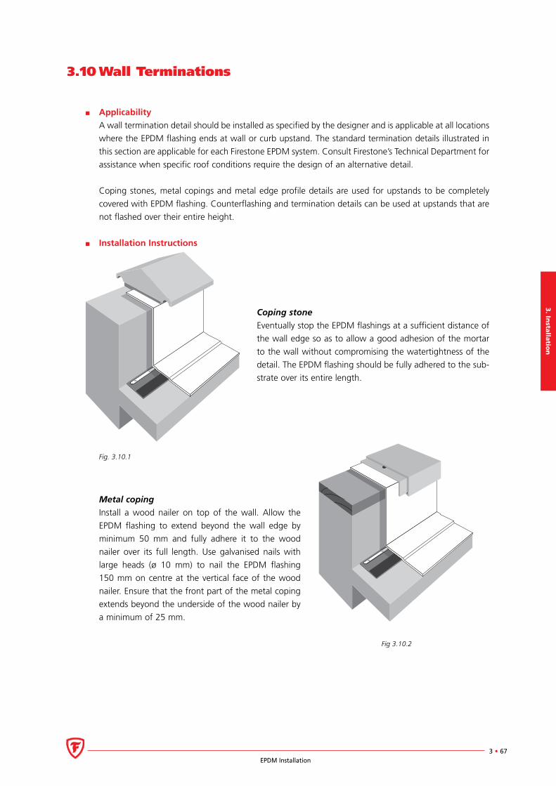
3. In
stalla
tion
3 • 67EPDM Installation
3.10 Wall Terminations
Applicability
A wall termination detail should be installed as specified by the designer and is applicable at all locations
where the EPDM flashing ends at wall or curb upstand. The standard termination details illustrated in
this section are applicable for each Firestone EPDM system. Consult Firestone’s Technical Department for
assistance when specific roof conditions require the design of an alternative detail.
Coping stones, metal copings and metal edge profile details are used for upstands to be completely
covered with EPDM flashing. Counterflashing and termination details can be used at upstands that are
not flashed over their entire height.
Installation Instructions
Coping stone
Eventually stop the EPDM flashings at a sufficient distance of
the wall edge so as to allow a good adhesion of the mortar
to the wall without compromising the watertightness of the
detail. The EPDM flashing should be fully adhered to the sub-
strate over its entire length.
Fig. 3.10.1
Metal coping
Install a wood nailer on top of the wall. Allow the
EPDM flashing to extend beyond the wall edge by
minimum 50 mm and fully adhere it to the wood
nailer over its full length. Use galvanised nails with
large heads (ø 10 mm) to nail the EPDM flashing
150 mm on centre at the vertical face of the wood
nailer. Ensure that the front part of the metal coping
extends beyond the underside of the wood nailer by
a minimum of 25 mm.
Fig 3.10.2
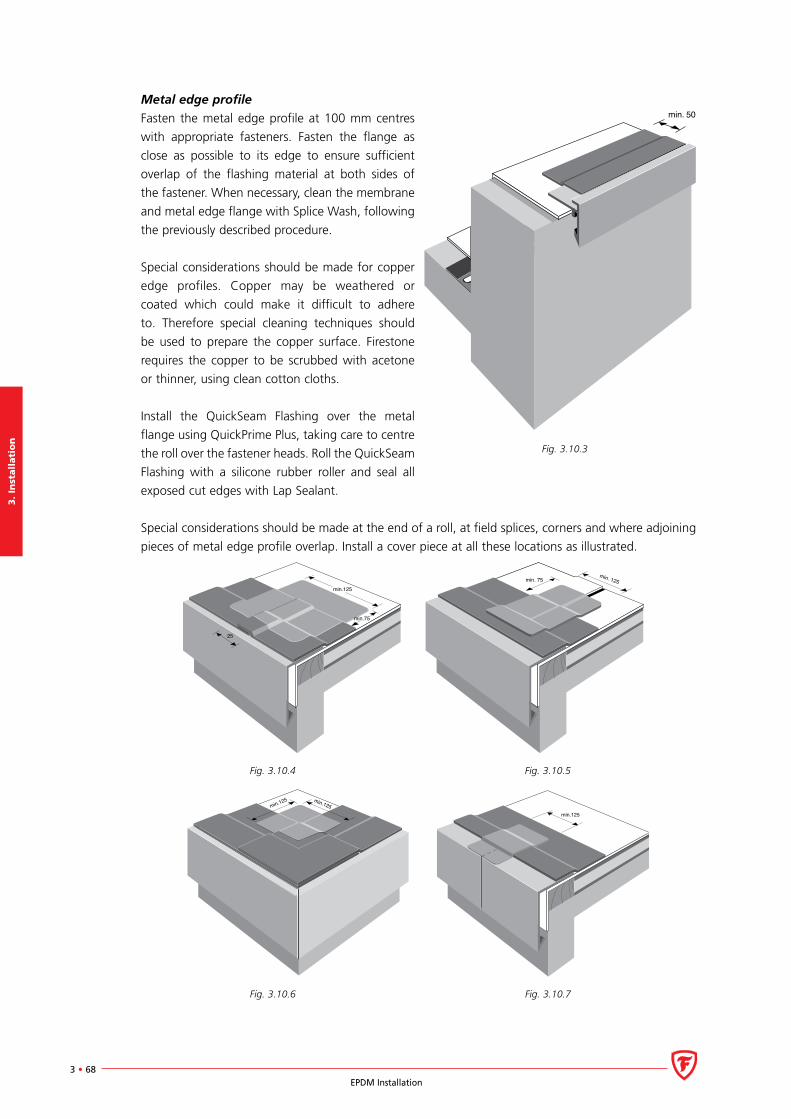
3.
Inst
all
ati
on
3 • 68EPDM Installation
Metal edge profile
Fasten the metal edge profile at 100 mm centres
with appropriate fasteners. Fasten the flange as
close as possible to its edge to ensure sufficient
overlap of the flashing material at both sides of
the fastener. When necessary, clean the membrane
and metal edge flange with Splice Wash, following
the previously described procedure.
Special considerations should be made for copper
edge profiles. Copper may be weathered or
coated which could make it difficult to adhere
to. Therefore special cleaning techniques should
be used to prepare the copper surface. Firestone
requires the copper to be scrubbed with acetone
or thinner, using clean cotton cloths.
Install the QuickSeam Flashing over the metal
flange using QuickPrime Plus, taking care to centre
the roll over the fastener heads. Roll the QuickSeam
Flashing with a silicone rubber roller and seal all
exposed cut edges with Lap Sealant.
Special considerations should be made at the end of a roll, at field splices, corners and where adjoining
pieces of metal edge profile overlap. Install a cover piece at all these locations as illustrated.
min.125
25
min.75
min. 75min. 125
Fig. 3.10.4 Fig. 3.10.5
min.125min.125
min.125
Fig. 3.10.6 Fig. 3.10.7
min. 50
Fig. 3.10.3

3. In
stalla
tion
3 • 69EPDM Installation
The monotrim metal profile edge does not require the above-described flashing method.
Fig. 3.10.8
Termination Bar
The required height for the EPDM flashing should be determined by local regulations. For situations
where this condition cannot be satisfied, Firestone requires that the flashing height exceeds the poten-
tial water level of a blocked drain. Suitable substrates for a Termination Bar are concrete, smooth bricks,
blocks or masonry. A termination bar may never be mounted to a wooden substrate.
Keep a minimum space of 5 mm between two adjoining bars. The termination bar must be installed
directly to the wall surface, not to existing flashings, sheet metal, etc. Pre-drill holes into the brick,
masonry or concrete and not into the soft mortar joint. A Termination Bar must be cut at inside and
outside corners. Do not bend the bar around the corners. Prior to installation of the Termination Bar,
pull back the topside of the membrane flashing 20 mm and apply a bead of Water Block between the
membrane and the wall.
Install the Termination Bar with an acceptable hammer plug system at 200 mm o.c.. A continuous
compression is required and may need additional fastening. Each Termination Bar must be fastened a
maximum of 25 mm from the end.
Apply a bead of Lap Sealant on the topside of the bar. At all locations where base flashings end, install
the Termination Bar vertically. Apply Lap Sealant to both sides of the bar.
Fig. 3.10.9
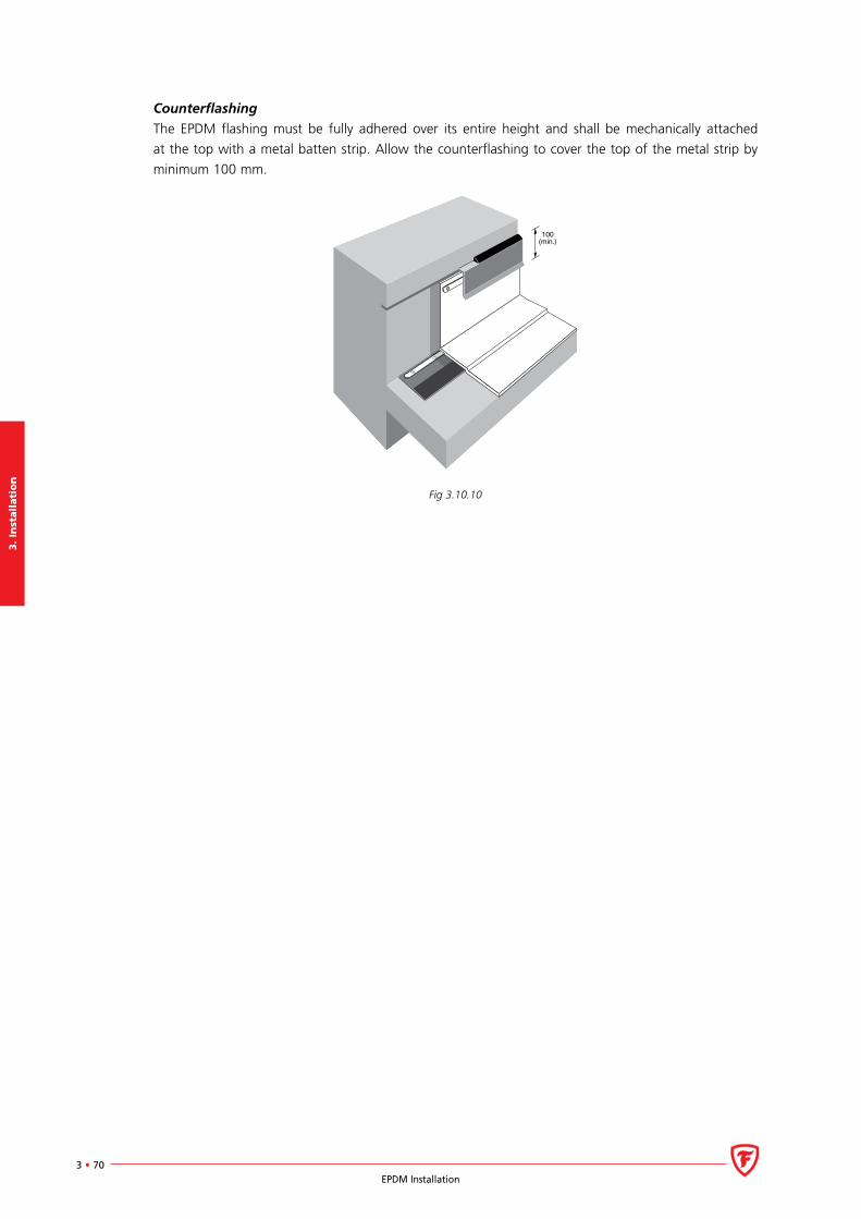
3.
Inst
all
ati
on
3 • 70EPDM Installation
Counterflashing
The EPDM flashing must be fully adhered over its entire height and shall be mechanically attached
at the top with a metal batten strip. Allow the counterflashing to cover the top of the metal strip by
minimum 100 mm.
100(min.)
Fig 3.10.10
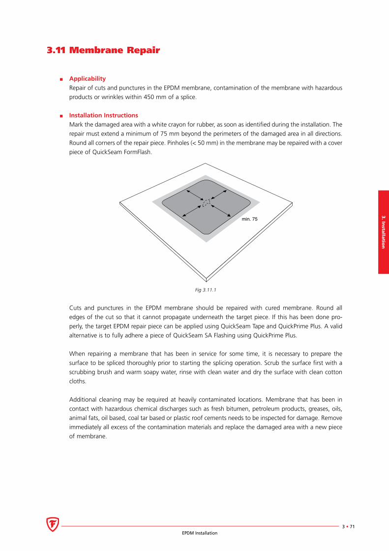
3. In
stalla
tion
3 • 71EPDM Installation
3.11 Membrane Repair
Applicability
Repair of cuts and punctures in the EPDM membrane, contamination of the membrane with hazardous
products or wrinkles within 450 mm of a splice.
Installation Instructions
Mark the damaged area with a white crayon for rubber, as soon as identified during the installation. The
repair must extend a minimum of 75 mm beyond the perimeters of the damaged area in all directions.
Round all corners of the repair piece. Pinholes (< 50 mm) in the membrane may be repaired with a cover
piece of QuickSeam FormFlash.
min. 75
Fig 3.11.1
Cuts and punctures in the EPDM membrane should be repaired with cured membrane. Round all
edges of the cut so that it cannot propagate underneath the target piece. If this has been done pro-
perly, the target EPDM repair piece can be applied using QuickSeam Tape and QuickPrime Plus. A valid
alternative is to fully adhere a piece of QuickSeam SA Flashing using QuickPrime Plus.
When repairing a membrane that has been in service for some time, it is necessary to prepare the
surface to be spliced thoroughly prior to starting the splicing operation. Scrub the surface first with a
scrubbing brush and warm soapy water, rinse with clean water and dry the surface with clean cotton
cloths.
Additional cleaning may be required at heavily contaminated locations. Membrane that has been in
contact with hazardous chemical discharges such as fresh bitumen, petroleum products, greases, oils,
animal fats, oil based, coal tar based or plastic roof cements needs to be inspected for damage. Remove
immediately all excess of the contamination materials and replace the damaged area with a new piece
of membrane.

3.
Inst
all
ati
on
3 • 72EPDM Installation
Wrinkles running toward or in a splice or within 450 mm of a splice must be cut out and repaired with
a covering piece of cured EPDM membrane without factory seams. Provide a splice that extends a mini-
mum of 75 mm beyond the perimeter of the cut in all directions. Use scissors to cut the wrinkles away,
laying them flat on the membrane. Adhere the loose parts of the membrane with QuickPrime Plus and
use small silicone rubber roller to roll the edges flat. Clean the area around the cut and repair with a
patch of cured membrane.
min. 100
EPDM
Fig. 3.11.2
3. In
stalla
tion
3 • 73EPDM Installation
3.12 Miscellaneous
In this section information is provided with regard to the following items:
Roof walkways.
Coating the EPDM membrane.
Temporary closure.
Lightning rod attachments.
Roof Walkways
Firestone QuickSeam EPDM Walkway Pads: lay out the pads so that the flat surface is in contact with the
completed EPDM membrane. Install each pad with a minimum spacing of 25 mm and a maximum of
150 mm to allow for cross drainage. If the installation of a Walkway Pad is over a field fabricated seam
or within 75 mm of a splice edge, cover the seam using QuickSeam FormFlash/Flashing. The QuickSeam
FormFlash/Flashing covering piece should extend a minimum of 150 mm beyond the Walkway Pad on
either side.
Prepare the mating surface of the EPDM membrane with QuickPrime Plus. Pre-cleaning with Splice Wash
may be required. Allow it to flash off. Ensure that the priming allows the strips beneath the pad to be
installed parallel to the slope of the roof. Remove the release paper from the strips, turn the Walkway
Pad over and place onto the EPDM membrane. Walk on the pad to press it into place. For loose laid
concrete pavers: place a layer of protection mat or an additional layer of EPDM membrane underneath
the pavers to isolate them from the roofing membrane. The protection layer must extend a minimum
of 50 mm beyond the paver.
Coating the EPDM membrane
Firestone EPDM systems do not require any additional protection with paint. If a coating is specified for
other reasons, make sure that all repairs are completed prior to its application. Allow the field mem-
brane and flashings to weather for approximately two weeks prior to application of the paint. Clean all
membrane surfaces prior to application of the coating using a pressure washer and clean warm water.
Refer to product information sheet of the Acrylic Top PC-100 coating for application instructions.
Temporary closure
Temporary closures can prevent moisture from damaging the completed section of the new installation.
Flashings, Terminations and temporary closures must be completed to provide a watertight condition at
the end of each working day.
Mark the free edge of the uncompleted section on the substrate. Fold the membrane back a minimum
of 200 mm. Use a chalkline to mark a straight line on the substrate 100 mm within the first marks. Apply
a bead of Water Block or Lap Sealant over the chalkline at a rate of 3 lin.m./tube. Let the membrane fall
freely into the mastic and install some temporary ballast to put the seam under continuous compression.
The next working day, use a chalkline to trim a portion of 200 mm at the end of the membrane.
Lightning rod attachment
Refer to the illustrations at the end of this document for additional information.

3.
Inst
all
ati
on
3 • 74EPDM Installation
Related Documents


