Hydraulic Power (pumps) Chapter (2)

Welcome message from author
This document is posted to help you gain knowledge. Please leave a comment to let me know what you think about it! Share it to your friends and learn new things together.
Transcript

Hydraulic Power (pumps)
Chapter (2)
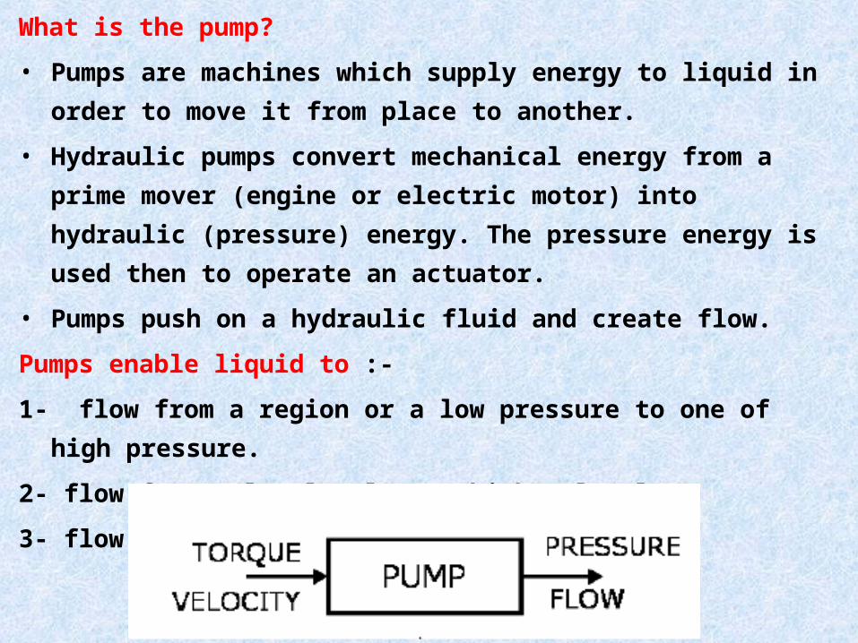
What is the pump?
• Pumps are machines which supply energy to liquid in order to move it
from place to another.
• Hydraulic pumps convert mechanical energy from a prime mover
(engine or electric motor) into hydraulic (pressure) energy. The pressure
energy is used then to operate an actuator.
• Pumps push on a hydraulic fluid and create flow.
Pumps enable liquid to :-
1- flow from a region or a low pressure to one of high pressure.
2- flow from a low level to a higher level.
3- flow at a faster rate.

Hydraulic Pumps
Non–Positive Displacement Pumps
Positive Displacement Pumps

An example of this pump is the centrifugal pump (impeller) and axial
pump (propeller). These pumps characterized by:
1- smooth continuous flow.
2- the output flow reduced as the circuit resistance increased.
3- it is not self priming, due to the clearance space between the
impeller and the housing
4- it is typically used in low pressure high volume flow applications.
5- due to the output flow changes with external resistance so they are
rarely used in hydraulic systems.
1- non positive displacement pumps (hydrodynamic)


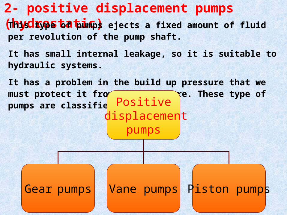
2- positive displacement pumps (hydrostatic)This type of pumps ejects a fixed amount of fluid per revolution of the pump shaft.
It has small internal leakage, so it is suitable to hydraulic systems.
It has a problem in the build up pressure that we must protect it from over pressure. These type of pumps are classified to:
Positivedisplacement
pumps
Gear pumps Vane pumps Piston pumps

1- high pressure capability ( up to 10000 psi.).
2- capable to over comes the pressure resulting from mechanical
loads and resistance to flow due to friction.
3- smaller size.
4- higher volumetric efficiency.
5- small changes in efficiency
6- can operate over a wide range of pressure requirement and
speed range.
Positive displacement pumps have the following advantage over the non positive displacement pumps.

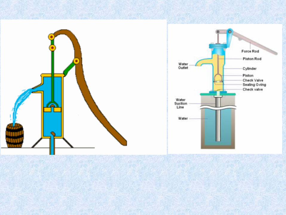
Reciprocating pumpsThese types of pump operate by using a reciprocating piston .
The liquid enters a pumping chamber via an inlet valve and is
pushed out via a outlet valve by the action of the piston or diaphragm.
Reciprocating pumps are generally very efficient and are suitable for
very high heads at low flows.


This type of pump is self priming as it can draw liquid from a level
below the suction flange even if the suction pipe is not evacuated.


SuctionDischarge

Pump Parameters
1- Displacement Volume (VD)
It is the volume of liquid suction by the pump per revolution
revmLDVD32
4
D = Diameter (Bore)
L = Stroke

2- Theoretical Volume Flow Rate (Qth)
It is the volume flow rate of liquid suction by the pump per second
smNVQ PDth3
3- Theoretical Power Consumption PowerInput lTheoretica thQP
Pump theacross Difference Pressure
inletexit PPP
P
Where
4- Theoretical Torque (Tth)
2
Power lTheoretica Dth
VPT
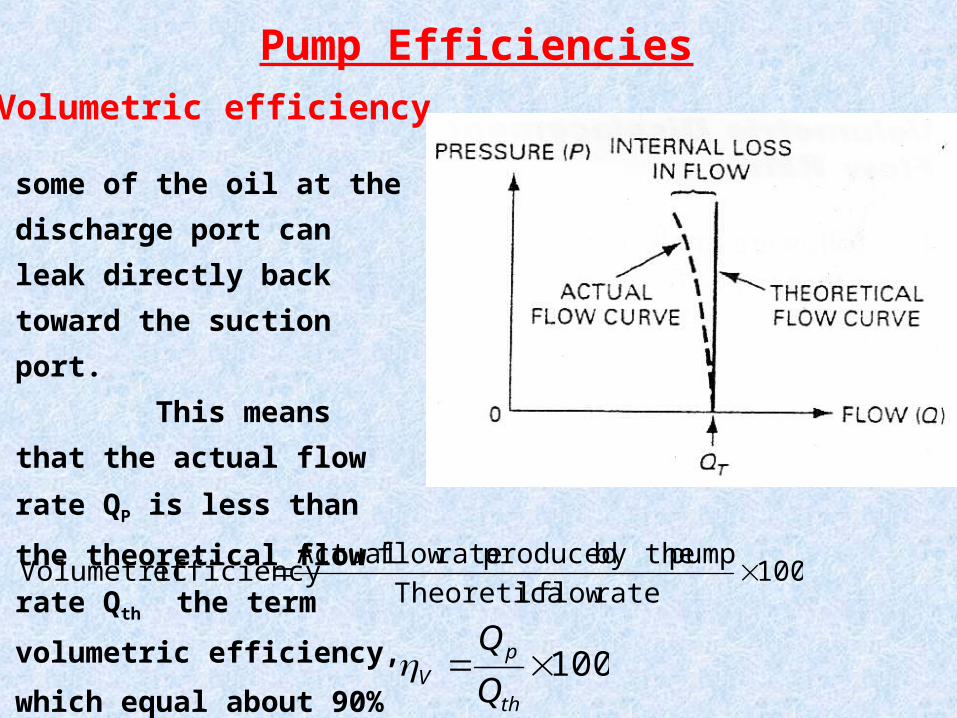
Pump Efficiencies
1- Volumetric efficiency
100rate flow lTheoretica
pump by the produced rate flow Actualefficiency Volumetric
some of the oil at the discharge
port can leak directly back
toward the suction port.
This means that the
actual flow rate QP is less than
the theoretical flow rate Qth
the term volumetric efficiency,
which equal about 90%
100th
pV Q
Q

100Pump todelivered Torque Actual
pump theoperate torequired Torque lTheoreticam
100A
thm T
T
This indicates the amount of energy losses that occur in pumps,
not taking into account the leakages. These losses include:
• Friction in bearing and other moving parts and
• Energy losses due to fluid turbulence.
is given by the equation,
2- Mechanical efficiency

pump todeliveredPower Actual
pump todeliveredPower lTheoreticaefficiency Overall
If both volumetric and mechanical efficiencies are known, the overall
efficiency can be computed as follows
The actual power delivered to a pump from a prime mover through
a rotating shaft is known as Brake power and the actual power
delivered by a pump to a fluid is known as hydraulic power.
3- Overall Efficiency
vm 0efficiency Overall

4- Leakage Flow Rate (QL)
PDVL
thVL
thVthL
PumpthL
NVQ
QQQ
QQQ
1
1

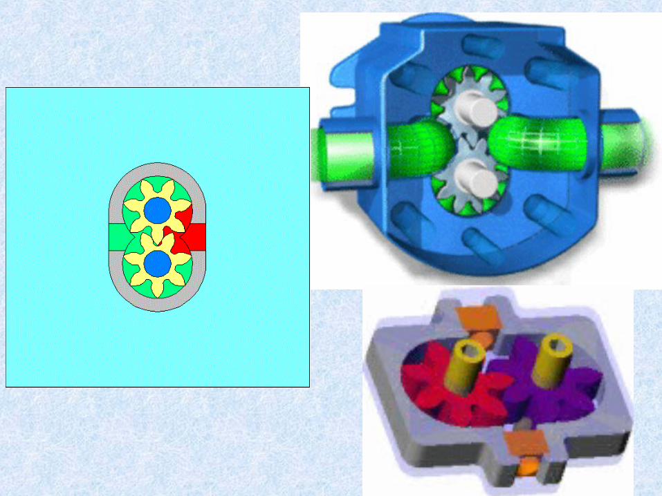
A- Gear pumps1- External gear pump
The operation of the external gear pump is based on the carrying of fluid
between the teeth of the meshing gears and the pump housing. One of the
gears is connected to the drive shaft and the second gear is driven by the
meshing of the driven gear.


The operation of the pump is illustrated as following as shown in the figure.
1- vacuum is carried in the inlet port of the pump which connected to the tank.
2- oil is carried around housing in champers formed between tooth and housing.
3- then it is forced out from the output port of the pump as tooth go back into mesh.

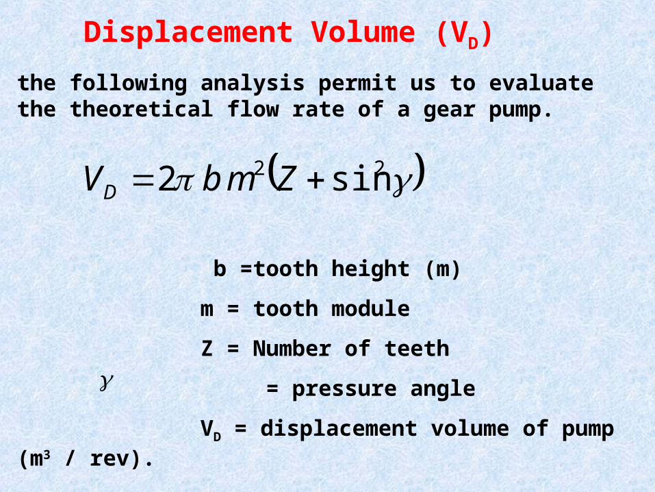
the following analysis permit us to evaluate the theoretical flow rate of a gear pump.
b =tooth height (m)
m = tooth module
Z = Number of teeth
= pressure angle
VD = displacement volume of pump (m3 / rev).
Displacement Volume (VD)
22 sin 2 ZmbVD

Typical displacements to 250 cm3/r
Typical pressures to 250 bar
Fixed displacement only
Good speed range, limited indirect
drive capability, simple multiple
assemblies
Generally noisy
Good contamination sensitivity
Poor serviceability
Compact, low weight
Low cost.
Typical displacements to 250 cm3/r
Typical pressures to 250 bar
Fixed displacement only
Good speed range, limited indirect
drive capability, simple multiple
assemblies
Generally noisy
Good contamination sensitivity
Poor serviceability
Compact, low weight
Low cost.
EXTERNAL GEAR PUMP CHARACTERISTICSEXTERNAL GEAR PUMP CHARACTERISTICS

Disadvantages (Problems) of External gear pump
1- Heating, which comes from,
A- leakage of oil
B- air in oil
C- very high pressure
2- High noise, which comes from,
A- Leakage of oil from small hollow
B- vibration
3- Decrease in pressure, which comes from,
Internal leakage between input and output when the pressure increase. This is due to the clearance between teeth and body increased or the teeth between the two meshing gears.

Advantage of increasing number of teeth
1- can over come higher pressure.
2- can work on higher pressure.
3- lower noise.
4- better continuity flow.
5- discharge does not increase.

1
3
4
25
6
المضخة -1 جسم
قائد -2 ترس
منقاد -3 ترس
سحب -4 فتحة
طرد -5 فتحة
هاللي -6 فراغ
2-Internal gear pump


Internal gear pump consists of
1- an internal gear ,
2- a regular spur gear,
3- crescent shaped seal
4- external housing.

The internal gear uses two rotating gears which un-mesh at the
suction side of the pump to create voids which allow atmospheric
pressure to force fluid into the pump. The spaces between the gear
teeth transport the fluid on either side of a crescent to the discharge
side, and then the gears re-mesh to discharge the fluid. Viking's
internal gear design has an outer drive gear (rotor- shown in orange)
which turns the inner, driven ear

1. Liquid enters the suction port between the rotor (exterior gear) and idler (small interior gear) teeth. 2. Liquid travels through the pump between the teeth of the gears. The crescent shape divides the liquid and acts as a seal between the suction and discharge ports.3. The pump head is now nearly flooded, just prior to forcing the liquid out of the discharge port. Intermeshing gears of the idler and rotor form locked pockets for the liquid which assures volume control.4. Rotor and idler teeth mesh completely to form a seal from the discharge and suction ports. This seal forces the liquid out of the discharge port.


The advantage of internal gear pump is that, it has a small size also it has low pressure , so it used on piston pump as a lubricated unit to it.
the following analysis permit us to evaluate the volume displacement of a gear pump.
b =tooth height (m)
m = tooth module
Z = Number of teeth
h =gear width (m)
VD = displacement volume of pump(m3 / rev).
ZhbmVD
Displacement Volume (VD)

Typical displacements to 250 cm3/r
Typical pressures to 250 bar
Fixed displacement only
Good speed range
Simple multiple assemblies
Low noise
Good contamination sensitivity
Poor serviceability
Good fluid compatibility.
Typical displacements to 250 cm3/r
Typical pressures to 250 bar
Fixed displacement only
Good speed range
Simple multiple assemblies
Low noise
Good contamination sensitivity
Poor serviceability
Good fluid compatibility.
Internal Gear Pump CharacteristicsInternal Gear Pump Characteristics

1- Only two moving parts.
2- Ideal for high-viscosity liquids.
3- Constant and even discharge regardless of pressure conditions.
4- Operates well in either direction.
5- Can be made to operate with one direction of flow with either rotation.
6- Single adjustable end clearance.
7- Easy to maintain.
8- Flexible design offers application customization.
Advantages
Disadvantages
1- Usually requires moderate speeds.
2- Medium pressure limitations.
3- One bearing runs in the product pumped.
4- Overhung load on shaft bearing.

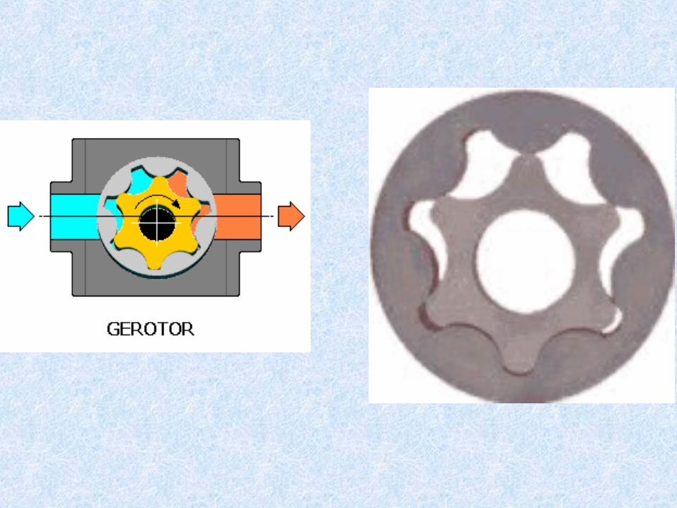
The gerotor pump operates very much like the crescent shape gear
pump. the inner gear rotate to around the outer gear caring oil
between the teeth then at the
small area it begin to push the
oil at the outlet port.
The inner gear has one
teeth less than the outer gear.
3- Ring Gear pump (Gerotor Pump)

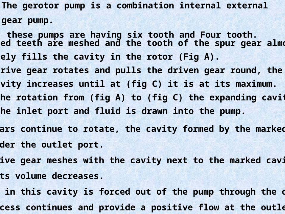
The gerotor pump is a combination internal external gear pump.
these pumps are having six tooth and Four tooth.
1- Two marked teeth are meshed and the tooth of the spur gear almost
completely fills the cavity in the rotor (Fig A).
2- As the drive gear rotates and pulls the driven gear round, the volume of
the cavity increases until at (fig C) it is at its maximum.
3- During the rotation from (fig A) to (fig C) the expanding cavity is
under the inlet port and fluid is drawn into the pump.
4- As the gears continue to rotate, the cavity formed by the marked teeth
moves under the outlet port.
5- As the drive gear meshes with the cavity next to the marked cavity in the
rotor, its volume decreases.
6- The fluid in this cavity is forced out of the pump through the outlet port.
this process continues and provide a positive flow at the outlet.


the following analysis permit us to evaluate the volume displacement of a gear pump.
Z = Number of rotor teeth
b =gear width (m)
VD = displacement volume of pump(m3 / rev).
minmax AAbZVD
Displacement Volume (VD)

Advantages
1- High speed
2- High pressure
3- No overhung bearing loads
4- Relatively quiet operation
5- Design accommodates wide variety of materials
1- Four bushings in liquid area
2- No solids allowed
3- Fixed End Clearances
Disadvantages·

This type of pump operate in a similar way of external gear pump
but both lobes are driven externally so that they do not actually
contact each other, so they are quieter than other types of gear
pumps. Due to the less space
of contact surface of the insider
lobe, the output will have greater
amount of pulsation also the
volumetric displacement is greater
than any type of gear pumps.
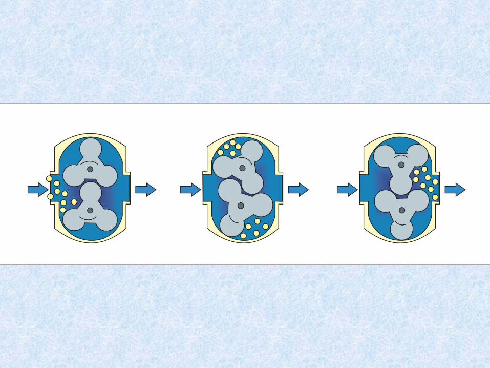
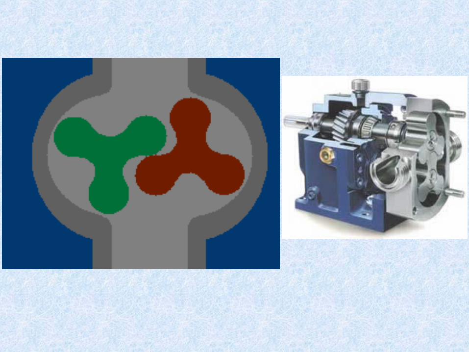
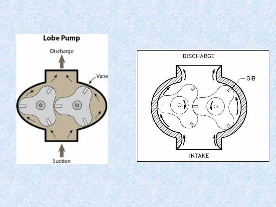
4- lobe pump


1. As the lobes come out of mesh, they create expanding volume on
the inlet side of the pump. Liquid flows into the cavity and is
trapped by the lobes as they rotate.
2. Liquid travels around the interior of the casing in the pockets
between the lobes and the casing -- it does not pass between the lobes.
3. Finally, the meshing of the lobes forces liquid through the outlet
port under pressure.


Advantages
Disadvantages
1- Pass medium solids
2- No metal-to-metal contact
3- Superior CIP/SIP capabilities
4- Long term dry run (with lubrication to seals)
5- Non-pulsating discharge
1- Requires timing gears
2- Requires two seals
3- Reduced lift with thin liquids
Related Documents