International Journal of Civil Engineering and Technology (IJCIET), ISSN 0976 – 6308 (Print), ISSN 0976 – 6316(Online), Volume 6, Issue 5, May (2015), pp. 10-22 © IAEME 10 FINITE ELEMENT COMPUTATION OF THE BEHAVIORAL MODEL OF MAT FOUNDATION Oustasse Abdoulaye Sall 1* , Makhaly Ba 1 , Mapathé Ndiaye 1 , Meissa Fall 1 , Yves Berthaud 2 , Ibrahima Mbaye 3 , Mathioro Fall 1 1 Département de Génie Civil, UFR SI-Université de Thiès, Thiès, Sénégal 2 UFR Ingénierie, Université Pierre et Marie Curie, Paris, France 3 Département de Mathématiques, UFR SET-Université de Thiès, Thiès, Sénégal ABSTRACT In this work the influence of soil mechanical properties on the displacements of mat foundation is studied. It was introduced the soil-structure interaction that is modeled by two parameters, the modulus of subgrade vertical reaction (k) and the modulus of subgrade horizontal reaction (2T). These two parameters are dependent on the geometrical and mechanical characteristics of the system. It appears from this study that the modulus of vertical subgrade reaction is not an intrinsic characteristic but depends on the parameters of the soil and the concrete (E s ν s , E b and ν b ) and the dimensions of the plate (so dependent on the superstructure). It is clear from this analysis that the foundation soil parameters are more influential than those of the plate. Keywords: Mat foundation, Soil-structure interaction, Mechanical properties, Finite Element Computation. 1. INTRODUCTION Developments in civil engineering constructions and especially disorders observed in the supporting structures of civil engineering works pushed the designers to better take into account soil- structure interaction in the process of calculating the foundation structures. Thus, several authors have worked on the modulus of subgrade reaction that is an important parameter in consideration of the soil-structure interface. This work is a contribution to the finite element analysis of foundation slab resting on elastic soil. The behavioral model is established, as well as all elementary matrices of the model and the matrix assembly. For solving the finite element model, the numerical solver FreeFem © will be used. INTERNATIONAL JOURNAL OF CIVIL ENGINEERING AND TECHNOLOGY (IJCIET) ISSN 0976 – 6308 (Print) ISSN 0976 – 6316(Online) Volume 6, Issue 5, May (2015), pp. 10-22 © IAEME: www.iaeme.com/Ijciet.asp Journal Impact Factor (2015): 9.1215 (Calculated by GISI) www.jifactor.com IJCIET ©IAEME

Welcome message from author
This document is posted to help you gain knowledge. Please leave a comment to let me know what you think about it! Share it to your friends and learn new things together.
Transcript
International Journal of Civil Engineering and Technology (IJCIET), ISSN 0976 – 6308 (Print), ISSN 0976 – 6316(Online), Volume 6, Issue 5, May (2015), pp. 10-22 © IAEME
10
FINITE ELEMENT COMPUTATION OF THE
BEHAVIORAL MODEL OF MAT FOUNDATION
Oustasse Abdoulaye Sall1*
, Makhaly Ba1, Mapathé Ndiaye
1, Meissa Fall
1,
Yves Berthaud2, Ibrahima Mbaye
3, Mathioro Fall
1
1Département de Génie Civil, UFR SI-Université de Thiès, Thiès, Sénégal
2UFR Ingénierie, Université Pierre et Marie Curie, Paris, France
3Département de Mathématiques, UFR SET-Université de Thiès, Thiès, Sénégal
ABSTRACT
In this work the influence of soil mechanical properties on the displacements of mat
foundation is studied. It was introduced the soil-structure interaction that is modeled by two
parameters, the modulus of subgrade vertical reaction (k) and the modulus of subgrade horizontal
reaction (2T). These two parameters are dependent on the geometrical and mechanical characteristics
of the system. It appears from this study that the modulus of vertical subgrade reaction is not an
intrinsic characteristic but depends on the parameters of the soil and the concrete (Es νs, Eb and νb)
and the dimensions of the plate (so dependent on the superstructure). It is clear from this analysis
that the foundation soil parameters are more influential than those of the plate.
Keywords: Mat foundation, Soil-structure interaction, Mechanical properties, Finite Element
Computation.
1. INTRODUCTION
Developments in civil engineering constructions and especially disorders observed in the
supporting structures of civil engineering works pushed the designers to better take into account soil-
structure interaction in the process of calculating the foundation structures. Thus, several authors
have worked on the modulus of subgrade reaction that is an important parameter in consideration of
the soil-structure interface.
This work is a contribution to the finite element analysis of foundation slab resting on elastic
soil. The behavioral model is established, as well as all elementary matrices of the model and the
matrix assembly. For solving the finite element model, the numerical solver FreeFem©
will be used.
INTERNATIONAL JOURNAL OF CIVIL ENGINEERING AND
TECHNOLOGY (IJCIET)
ISSN 0976 – 6308 (Print)
ISSN 0976 – 6316(Online)
Volume 6, Issue 5, May (2015), pp. 10-22
© IAEME: www.iaeme.com/Ijciet.asp
Journal Impact Factor (2015): 9.1215 (Calculated by GISI)
www.jifactor.com
IJCIET
©IAEME
International Journal of Civil Engineering and Technology (IJCIET), ISSN 0976 – 6308 (Print), ISSN 0976 – 6316(Online), Volume 6, Issue 5, May (2015), pp. 10-22 © IAEME
11
In the following, after solving the fundamental equation, the influence of different parameters
(Es νs, Eb, νb and e) on the behavioral model of the foundation will be highlighted.
2. PRESENTATION OF THE CALCULATION MODEL
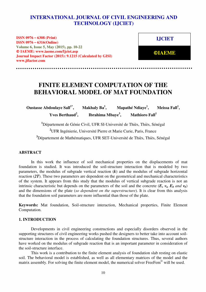
For analysis of raft foundations, the soil is considered as a springs assembly (with elastic
modulus k) infinitely close to each other and connected by an elastic membrane (horizontal modulus
of reaction = 2T) (Figure 1).
Figure 1 A schematisation of the problem
The theory of plate accounting for the soil-structure interaction (biparametric model) leads to
mat foundation behavioral law (equation 1):
� ������� + 2 ���
��� + ����� � − 2 ���
�� + ��� � + �� = ���, �� (1)
Where D is the flexural rigidity of the plate and is given by:
� = ������������ (2)
With:
Eb : elastic modulus of the material constituting the plate,
e: the thickness of the plate;
νb : Poisson's ratio of the plate;
k : is the modulus of subgrade reaction.
w : is the deflection
The parameter k has been studied by several authors. All authors coming after Biot (1935)
tend to give higher values to the soil reaction modulus based on input parameters (Sall, 2015). As the
goal is to better understand the deformations, in this research (for more security), it would be better
to use in the calculations the reaction modulus equation proposed by Biot (1935). In this equation,
the displacements of plate points increase if the soil modulus of reaction increases. This equation is
expressed as follow:
International Journal of Civil Engineering and Technology (IJCIET), ISSN 0976 – 6308 (Print), ISSN 0976 – 6316(Online), Volume 6, Issue 5, May (2015), pp. 10-22 © IAEME
12
� = �, !�"��� #�"$�
�%&
(3)
Equation 3 has been improved by Vesic (1963), as follow:
� = �,'!�"��� � �"$�
�������%��,��(
(4)
where:
Es is the modulus of subgrade,
νs is the Poisson's ratio of the subgrade;
B is the width of the foundation;
Eb is the Young modulus of the concrete foundation;
I is the moment of inertia of the cross section of the concrete.
T is the horizontal elastic modulus of subgrade reaction. Vlasov (1949) proposes the following
relation:
= �")����"���*�"����"�� + ,�-
� ./ (5)
To a relatively deep layer of soil where the normal stress may vary with depth, it is possible
to use, for the function Φ (z), the non-linear continuous variable defined by equation 5a. Φ(z) is a
function which describes the variation of the displacement w(x, y) along the z axis, such that:
,�0� = 1 34. ,�5� = 0
Selvadurai (1979) suggests two expressions of Φ (z), respectively:
,�/� = �1 − 6-� (6a)
,�7� = 89:;<�-�6�=>?
89:;�=@> � (6b)
H: thickness of the soil layer (depth of the rigid substratum).
3. STUDY OF THE PARAMETER K
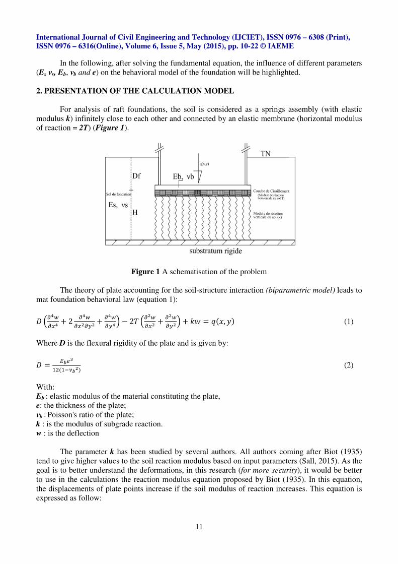
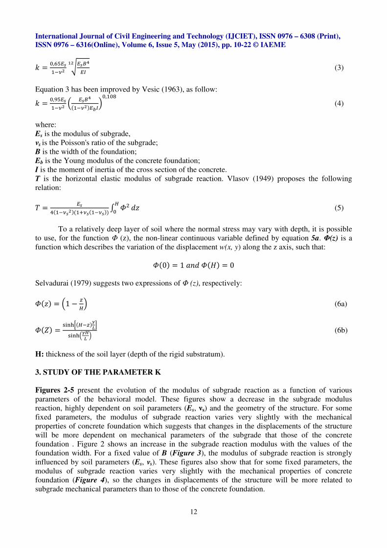
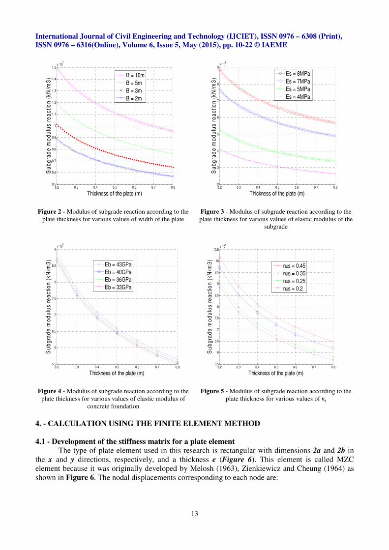
Figures 2-5 present the evolution of the modulus of subgrade reaction as a function of various
parameters of the behavioral model. These figures show a decrease in the subgrade modulus
reaction, highly dependent on soil parameters (Es, νs) and the geometry of the structure. For some
fixed parameters, the modulus of subgrade reaction varies very slightly with the mechanical
properties of concrete foundation which suggests that changes in the displacements of the structure
will be more dependent on mechanical parameters of the subgrade that those of the concrete
foundation . Figure 2 shows an increase in the subgrade reaction modulus with the values of the
foundation width. For a fixed value of B (Figure 3), the modulus of subgrade reaction is strongly
influenced by soil parameters (Es, νs). These figures also show that for some fixed parameters, the
modulus of subgrade reaction varies very slightly with the mechanical properties of concrete
foundation (Figure 4), so the changes in displacements of the structure will be more related to
subgrade mechanical parameters than to those of the concrete foundation.
International Journal of Civil Engineering and Technology (IJCIET), ISSN 0976 – 6308 (Print), ISSN 0976 – 6316(Online), Volume 6, Issue 5, May (2015), pp. 10-22 © IAEME
13
Figure 2 - Modulus of subgrade reaction according to the
plate thickness for various values of width of the plate
Figure 3 - Modulus of subgrade reaction according to the
plate thickness for various values of elastic modulus of the
subgrade
Figure 4 - Modulus of subgrade reaction according to the
plate thickness for various values of elastic modulus of
concrete foundation
Figure 5 - Modulus of subgrade reaction according to the
plate thickness for various values of νs
4. - CALCULATION USING THE FINITE ELEMENT METHOD
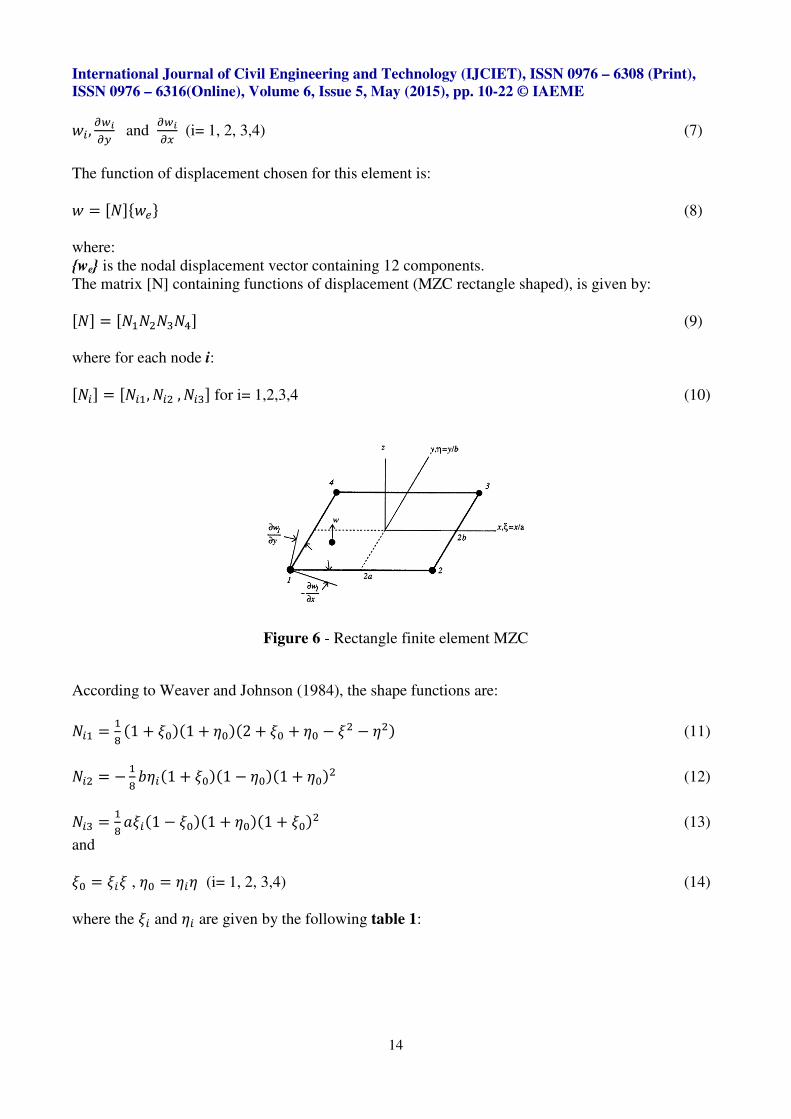
4.1 - Development of the stiffness matrix for a plate element The type of plate element used in this research is rectangular with dimensions 2a and 2b in
the x and y directions, respectively, and a thickness e (Figure 6). This element is called MZC
element because it was originally developed by Melosh (1963), Zienkiewicz and Cheung (1964) as
shown in Figure 6. The nodal displacements corresponding to each node are:
0.2 0.3 0.4 0.5 0.6 0.7 0.80.5
0.6
0.7
0.8
0.9
1
1.1
1.2
1.3
1.4
1.5x 10
7
Thickness of the plate (m)
Su
bg
rad
e m
od
ulu
s r
ea
cti
on
(k
N/m
3)
B = 10m
B = 5m
B = 3m
B = 2m
0.2 0.3 0.4 0.5 0.6 0.7 0.82
3
4
5
6
7
8
9x 10
6
Thickness of the plate (m)
Su
bg
rad
e m
od
ulu
s r
ea
cti
on
(k
N/m
3)
Es = 8MPa
Es = 7MPa
Es = 5MPa
Es = 4MPa
0.2 0.3 0.4 0.5 0.6 0.7 0.85.5
6
6.5
7
7.5
8
8.5
9x 10
6
Thickness of the plate (m)
Su
bg
rad
e m
od
ulu
s r
ea
cti
on
(k
N/m
3)
Eb = 43GPa
Eb = 40GPa
Eb = 36GPa
Eb = 33GPa
0.2 0.3 0.4 0.5 0.6 0.7 0.85.5
6
6.5
7
7.5
8
8.5
9
9.5
10
10.5x 10
6
Thickness of the plate (m)
Su
bg
rad
e m
od
ulu
s r
ea
cti
on
(k
N/m
3)
nus = 0.45
nus = 0.35
nus = 0.25
nus = 0.2
International Journal of Civil Engineering and Technology (IJCIET), ISSN 0976 – 6308 (Print), ISSN 0976 – 6316(Online), Volume 6, Issue 5, May (2015), pp. 10-22 © IAEME
14
�A, ��B� and
��B�� (i= 1, 2, 3,4) (7)
The function of displacement chosen for this element is:
� = CDEF��G (8)
where:
{we} is the nodal displacement vector containing 12 components.
The matrix [N] containing functions of displacement (MZC rectangle shaped), is given by:
CDE = CD�D�DHD)E (9)
where for each node i:
CDAE = CDA�, DA� , DAHE for i= 1,2,3,4 (10)
Figure 6 - Rectangle finite element MZC
According to Weaver and Johnson (1984), the shape functions are:
DA� = �( �1 + I���1 + J���2 + I� + J� − I� − J�� (11)
DA� = − �( KJA�1 + I���1 − J���1 + J��� (12)
DAH = �( 3IA�1 − I���1 + J���1 + I��� (13)
and
I� = IAI , J� = JAJ (i= 1, 2, 3,4) (14)
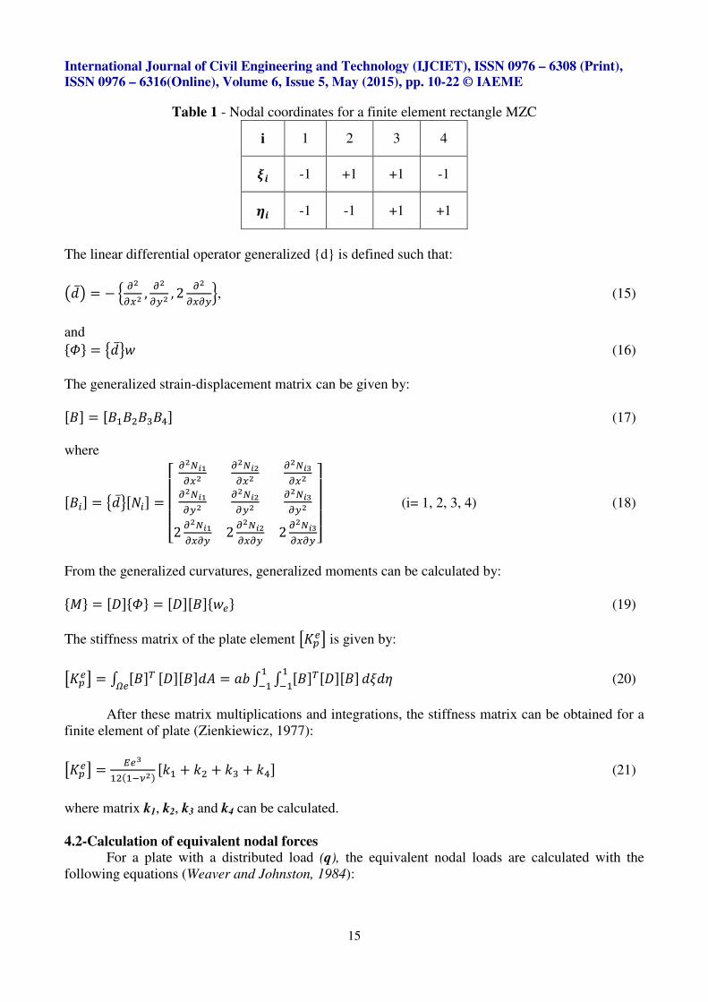
where the IA and JA are given by the following table 1:
International Journal of Civil Engineering and Technology (IJCIET), ISSN 0976 – 6308 (Print), ISSN 0976 – 6316(Online), Volume 6, Issue 5, May (2015), pp. 10-22 © IAEME
15
Table 1 - Nodal coordinates for a finite element rectangle MZC
i 1 2 3 4
LM -1 +1 +1 -1
NM -1 -1 +1 +1
The linear differential operator generalized {d} is defined such that:
O.Q = − R ��� , �
� , 2 ����S, (15)
and
F,G = T.U� (16)
The generalized strain-displacement matrix can be given by:
CVE = CV�V�VHV)E (17)
where
CVAE = T.UCDAE =WXXXY �ZB&
���ZB
���ZB�
���ZB&
��ZB
��ZB�
�
2 �ZB&��� 2 �ZB
��� 2 �ZB���� [\
\\] (i= 1, 2, 3, 4) (18)
From the generalized curvatures, generalized moments can be calculated by:
F^G = C�EF,G = C�ECVEF��G (19)
The stiffness matrix of the plate element _ a�b is given by:
_ a�b = + CVEcd� C�ECVE.e = 3K + + CVEcC�ECVE���
��� .I.J (20)
After these matrix multiplications and integrations, the stiffness matrix can be obtained for a
finite element of plate (Zienkiewicz, 1977):
_ a�b = ���������� C�� + �� + �H + �)E (21)
where matrix k1, k2, k3 and k4 can be calculated.
4.2-Calculation of equivalent nodal forces For a plate with a distributed load (q), the equivalent nodal loads are calculated with the
following equations (Weaver and Johnston, 1984):
International Journal of Civil Engineering and Technology (IJCIET), ISSN 0976 – 6308 (Print), ISSN 0976 – 6316(Online), Volume 6, Issue 5, May (2015), pp. 10-22 © IAEME
16
fA = + DAc�.ed (22)
Where
fA = 3K + + DAc�.I.J���
��� (23)
After development, the load vector for an element of plate can be obtained by:
4.3 - Determination of matrix modeling soil-structure interaction It is shown that the stiffness matrix [Ke] and the vector load {fe} of a finite element of a
Kirchhoff plate can be obtained by deriving the potential energy of the internal and external forces
acting on the plate. The rigidity of the sub-floor should be extracted from the soil deformation
energy. For clarity, the total strain energy in the plate element and the subgrade are expressed from
the work of Turhan (1992):
g� = �� + <��
�� , ��� , 2 ��
���?cdh � <��
�� , ��� , 2 ��
���? .e + �� + C���, ��Ecdh �C���, ��E.e +
�� + <��
�� , ���?c
dh 2i <���� , ��
�? .e (24)
where/
je is the area of a plate element, and all other terms have been previously defined.
The first part of the above equation shows the conventional stiffness matrix of the
plateC�k�E, differentiation of the second integral over settings (nodal displacements) returns a
matrixC�l�E, which represents the effect of axial stress in the soil. And the last term gives a matrix
C�m�E which represents the effect of shearing in the soil. Thus, the total strain energy of a plate
element can be written in the form:
g� = �� F��Gc�C�k�E + C�l�E + C�m�E�F��G (25)
Thus, the stiffness matrix for an element of the plate-soil foundation system is:
C��E = C�k�E + C�l�E + C�m�E (26)
4.3.1-Vertical bending stiffness matrixCnnoE The total strain energy in the soil in the vertical direction is:
�gl�� = �� + C���, ��Ecdh �C���, ��E.e (27)
For each column of soil under the plate element, the first stiffness matrix,CnnoE, is calculated
by minimizing the total energy (Uk)e by a ratio to each component of the displacement vector {wi}:
C�l�EAp = ��qr�h��B��s
(28)
Using the dimensionless coordinates (ξ, η) and combining (27) and (28) yields:
International Journal of Civil Engineering and Technology (IJCIET), ISSN 0976 – 6308 (Print), ISSN 0976 – 6316(Online), Volume 6, Issue 5, May (2015), pp. 10-22 © IAEME
17
C�l�EAp = �� �3K �
��B��s + + ��.I.J���
��� (29)
Displacements at any point coordinates (ξ, η) of the plate are constituted by the same form of
functions used in assessing the stiffness matrix of a plate element. Referring to the above equations
and substituting the shape functions of the plate member in the expression of w, give the following
stiffness matrix (12×12) to take account of the axial stress on the soil:
C�l�E = �3K + + CDEcCDE.I.J���
��� (30)
This matrix was developed by Chilton and Wekezer (1990), but all coefficients are false.
Using their coefficients, the finite element model does not provide movement when the rigid plate is
uniformly charged. Recognizing this problem, the authors have reassessed all the coefficients of the
matrix CnnoE, and the corrected coefficients gives exactly constant q/k on the move during the
simulation of a Winkler (1932) model for a distributed uniformly charged plate. The matrix is
partitioned into four square matrices (6×6):
C�l�E = �3K t �l� �l�u�v. �lHx (31)
4.3.2 - Stiffness matrix due to shear deformationsnyo The total strain energy in the shear effect is:
�gm�� = �� + <��
�� , ���?c
dh 2i <���� , ��
�? .e (32)
By minimizing this function of the deformation energy in relation to all the components of
the displacement vector of the plate, there are given the second matrix rigidity of the foundation
which is expressed as:
C�m�EAp = ��qz�h��B��s
(33)
Combining equations (31) and (32) and using the natural coordinates, it can be obtained the
following equation:
C�m�EAp = �� �2i�3K �
��B��s + + ∇�∇���.I.J���
��� (34)
where the displacement function, w, is as defined above.
Substituting the expression of w in equation (34) and performing the integrations and
differentiations, give the second matrix rigidity of the foundation, which is still a 12×12 matrix:
C�m�EAp = 2i3K + + | �} <�Z
�~ ?c <�Z�~ ? + �
� <�Z��?c <�Z
��?� .I.J���
��� (35)
C�m�E = 2i3K t �m� �m�u�v. �mHx (36)
International Journal of Civil Engineering and Technology (IJCIET), ISSN 0976 – 6308 (Print), ISSN 0976 – 6316(Online), Volume 6, Issue 5, May (2015), pp. 10-22 © IAEME
18
5. - DETERMINING OF THE COEFFICIENTS OF THE OVERALL MATRIX OF THE
SYSTEM
Using the standard procedure in the method of finite elements for the assembly of the
elements, the global stiffness matrix is represented in the form of a half band matrix. The global
stiffness matrix for the whole system is symbolically represented by capital letters, such as:
C`E = ∑ O_�ab + C�lE + C�mEQZh��� (37)
C`E = _ ab + C lE + C mE (38)
where Ne is the total number of finite elements of plate.
The final equation to solve is given by:
C`EF�G = F�G (39)
where [K] is the global stiffness matrix of the system, {W} the displacement vector and {F} is the
vector load applied to the system. For solving the finite element model, the numerical solver
FreeFem ++ is used.
6. PRESENTATION AND DISCUSSION OF RESULTS
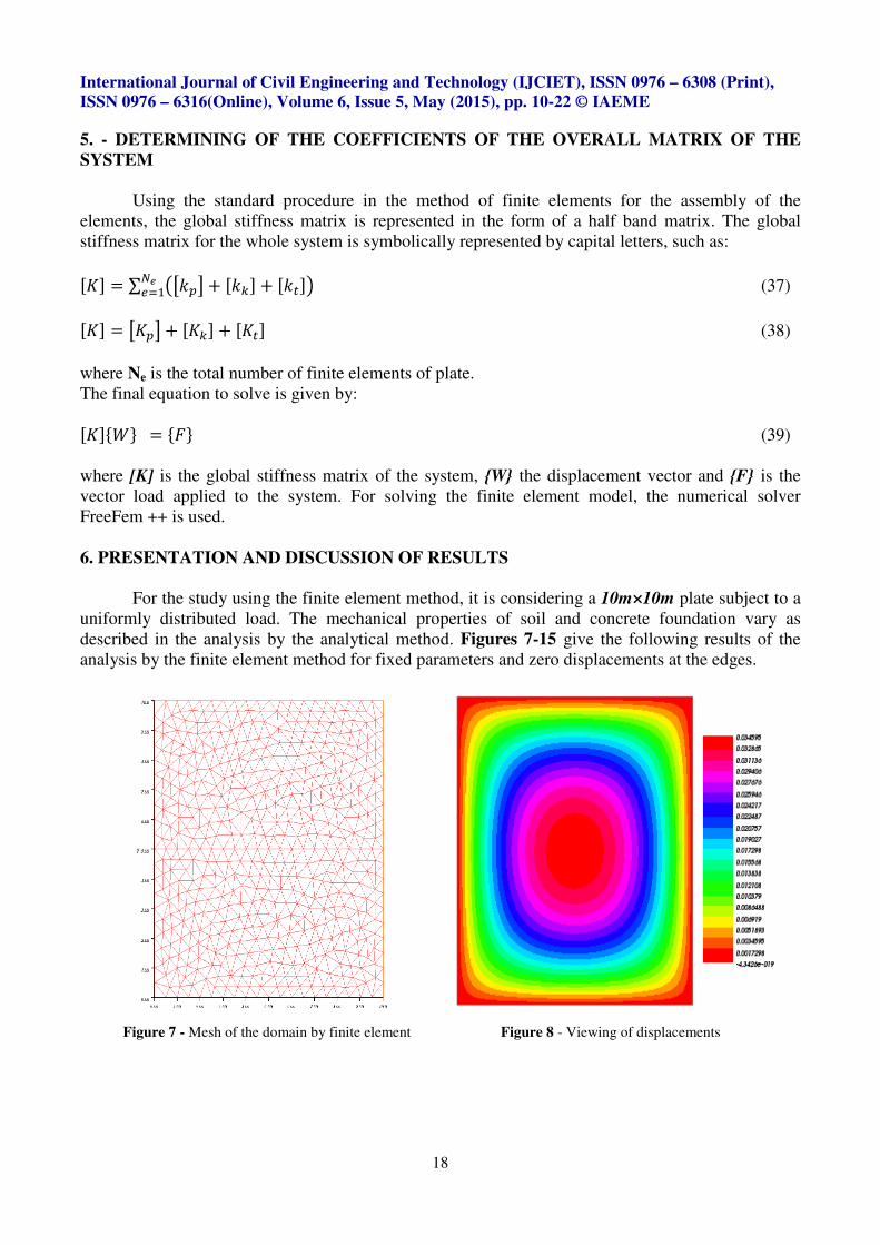
For the study using the finite element method, it is considering a 10m×10m plate subject to a
uniformly distributed load. The mechanical properties of soil and concrete foundation vary as
described in the analysis by the analytical method. Figures 7-15 give the following results of the
analysis by the finite element method for fixed parameters and zero displacements at the edges.
Figure 7 - Mesh of the domain by finite element
Figure 8 - Viewing of displacements
International Journal of Civil Engineering and Technology (IJCIET), ISSN 0976 – 6308 (Print), ISSN 0976 – 6316(Online), Volume 6, Issue 5, May (2015), pp. 10-22 © IAEME
19
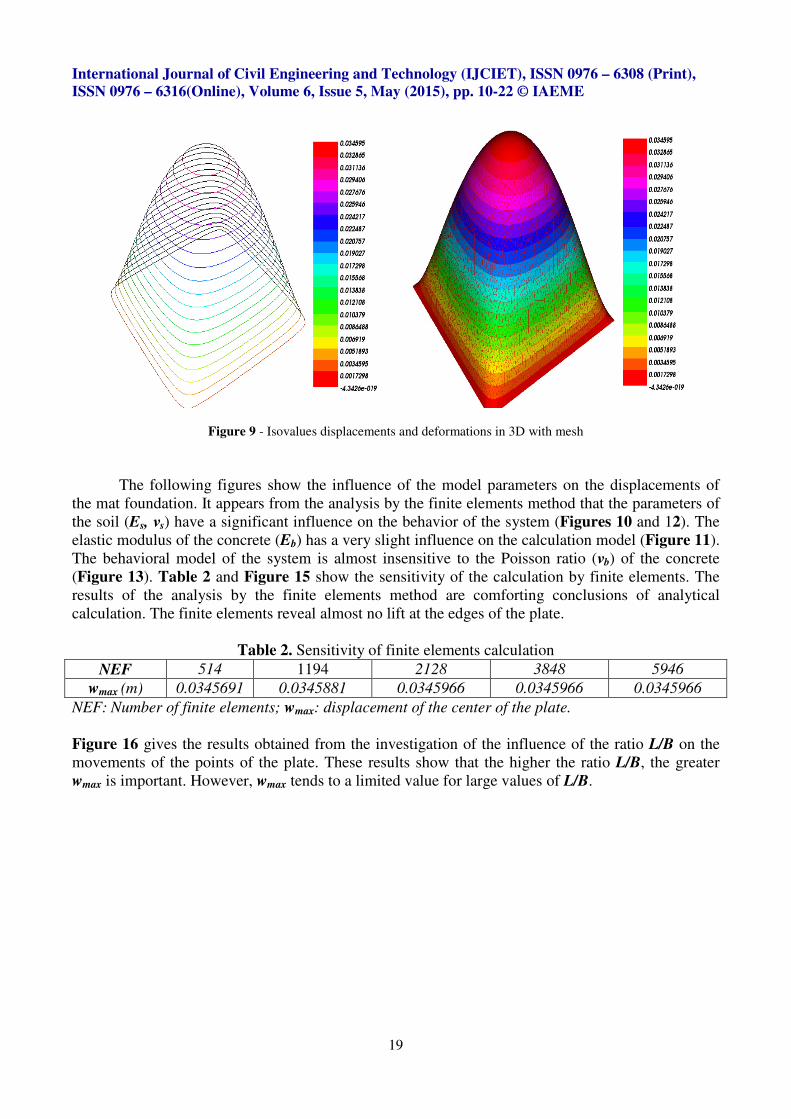
Figure 9 - Isovalues displacements and deformations in 3D with mesh
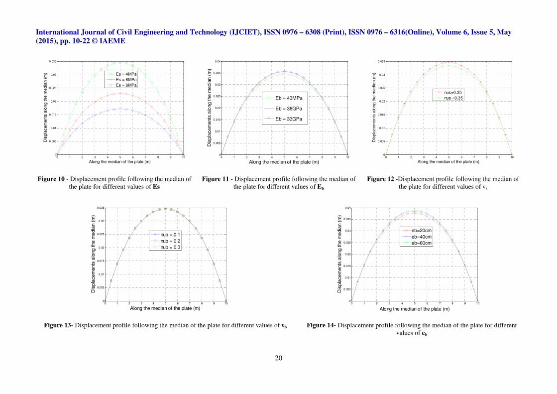
The following figures show the influence of the model parameters on the displacements of
the mat foundation. It appears from the analysis by the finite elements method that the parameters of
the soil (Es, νs) have a significant influence on the behavior of the system (Figures 10 and 12). The
elastic modulus of the concrete (Eb) has a very slight influence on the calculation model (Figure 11).
The behavioral model of the system is almost insensitive to the Poisson ratio (νb) of the concrete
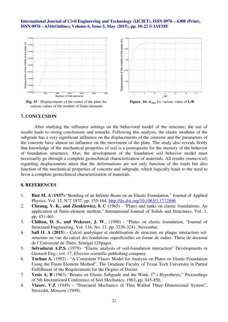
(Figure 13). Table 2 and Figure 15 show the sensitivity of the calculation by finite elements. The
results of the analysis by the finite elements method are comforting conclusions of analytical
calculation. The finite elements reveal almost no lift at the edges of the plate.
Table 2. Sensitivity of finite elements calculation
NEF 514 1194 2128 3848 5946
wmax (m) 0.0345691 0.0345881 0.0345966 0.0345966 0.0345966
NEF: Number of finite elements; wmax: displacement of the center of the plate.
Figure 16 gives the results obtained from the investigation of the influence of the ratio L/B on the
movements of the points of the plate. These results show that the higher the ratio L/B, the greater
wmax is important. However, wmax tends to a limited value for large values of L/B.
International Journal of Civil Engineering and Technology (IJCIET), ISSN 0976 – 6308 (Print), ISSN 0976 – 6316(Online), Volume 6, Issue 5, May (2015), pp. 10-22 © IAEME
20
Figure 10 - Displacement profile following the median of
the plate for different values of Es
Figure 11 - Displacement profile following the median of
the plate for different values of Eb
Figure 12 -Displacement profile following the median of
the plate for different values of νs
Figure 13- Displacement profile following the median of the plate for different values of νb
Figure 14- Displacement profile following the median of the plate for different
values of eb
0 1 2 3 4 5 6 7 8 9 100
0.005
0.01
0.015
0.02
0.025
0.03
0.035
Along the median of the plate (m)
Dis
pla
ce
me
nts
alo
ng
th
e m
ed
ian
(m
)
Es = 4MPa
Es = 6MPa
Es = 8MPa
0 1 2 3 4 5 6 7 8 9 100
0.005
0.01
0.015
0.02
0.025
0.03
0.035
0.04
Along the median of the plate (m)
Dis
pla
cem
ents
alo
ng the m
edia
n (
m)
Eb = 43MPa
Eb = 38GPa
Eb = 33GPa
0 1 2 3 4 5 6 7 8 9 100
0.005
0.01
0.015
0.02
0.025
0.03
0.035
Along the median of the plate (m)
Dis
pla
ce
me
nts
alo
ng
th
e m
ed
ian
(m
)
nus=0.25
nus =0.35
0 1 2 3 4 5 6 7 8 9 100
0.005
0.01
0.015
0.02
0.025
0.03
0.035
Along the median of the plate (m)
Dis
pla
cem
ents
alo
ng the m
edia
n (
m)
nub = 0.1
nub = 0.2
nub = 0.3
0 1 2 3 4 5 6 7 8 9 100
0.005
0.01
0.015
0.02
0.025
0.03
0.035
0.04
Along the median of the plate (m)
Dis
pla
cem
ents
alo
ng the m
edia
n (
m)
eb=20cm
eb=40cm
eb=60cm
International Journal of Civil Engineering and Technology (IJCIET), ISSN 0976 – 6308 (Print), ISSN 0976 – 6316(Online), Volume 6, Issue 5, May (2015), pp. 10-22 © IAEME
21
Fig. 15 - Displacements of the center of the plate for
various values of the number of finite elements
Figure. 16- wmax for various value of L/B
7. CONCLUSION
After studying the influence settings on the behavioral model of the structure, the use of
results leads to strong conclusions and remarks. Following this analysis, the elastic modulus of the
subgrade has a very significant influence on the displacements of the concrete and the parameters of
the concrete have almost no influence on the movement of the plate. The study also reveals firstly
that knowledge of the mechanical properties of soil is a prerequisite for the mastery of the behavior
of foundation structures. Also, the development of the foundation soil behavior model must
necessarily go through a complete geotechnical characterization of materials. All results (numerical)
regarding displacements attest that the deformations are not only function of the loads but also
function of the mechanical properties of concrete and subgrade, which logically leads to the need to
favor a complete geotechnical characterization of materials.
8. REFERENCES
1. Biot M. A (1937)-“Bending of an Infinite Beam on an Elastic Foundation,” Journal of Applied
Physics, Vol. 12, N°2 1937, pp. 155-164. http://dx.doi.org/10.1063/1.1712886
2. Cheung, Y. K., and Zienkiewicz, 0. C (1965) - "Plates and tanks on elastic foundations: An
application of finite-element method," International Journal of Solids and Structures, Vol. 1,
pp. 451-461.
3. Chilton, D. S., and Wekezer, J. W., (1990) - "Plates on elastic foundation, "Journal of
Structural Engineering, Vol. 116, No. 11, pp. 3236-3241, November.
4. Sall O. A (2015) - Calcul analytique et modélisation de structure en plaque interaction sol-
structure en vue du calcul des fondations superficielles en forme de radier- Thèse de doctorat
de l’Université de Thiès, Sénégal 125pages.
5. Selvadurai A.P.S. (1979)- “Elastic analysis of soil-foundation interaction” Developments in
Geotech Eng., vol. 17, Elsevier scientific publishing company.
6. Turhan A. (1992) - “A Consistent Vlasov Model for Analysis on Plates on Elastic Foundation
Using the Finite Element Method”. The Graduate Faculty of Texas Tech University in Partial
Fulfillment of the Requirements for the Degree of Doctor.
7. Vesic A. B (1963) “Beams on Elastic Subgrade and the Wink- ler
’s Hypothesis,” Proceedings
of 5th International Conference of Soil Mechanics, 1963, pp. 845-850.
8. Vlasov, V.Z (1949) - “Structural Mechanics of Thin Walled Three Dimensional System”,
Stroizdat, Moscow (1949).
0 1000 2000 3000 4000 5000 60000.0346
0.0346
0.0346
0.0346
0.0346
0.0346
0.0346
0.0346
0.0346
Number of finite elements
Dis
pla
ce
me
nt o
f th
e m
idd
le o
f th
e p
late
(m
)
2 4 6 8 10 12 14
0.04
0.045
0.05
0.055
0.06
L/B
Dis
pla
cem
en
t of
the
mid
dle
of th
e p
late
(m
)
International Journal of Civil Engineering and Technology (IJCIET), ISSN 0976 – 6308 (Print), ISSN 0976 – 6316(Online), Volume 6, Issue 5, May (2015), pp. 10-22 © IAEME
22
9. Vlazov V. Z and Leontiev U. N (1966) - “Beams, Plates and Shells on Elastic Foundations,”
Israel Program for Scientific Translations, Jerusalem, 1966.
10. Winkler E (1867) –“Die lehhre von der eiastizitat und Festigkeit”. Dominicus, Prague.
11. Weawer W. and Johnston, P. R., (1984) ‘‘Finite Element for Structural Analysis’’, Prentice-
HaU, Inc., Englewood Cliffs, NJ. 12. Zienkiewicz, O. C. (1977) ‘‘the Finite Element Method”, 3rd ed., McGraw-HiULtd., London,
1977.
Related Documents