3-1 Samsung Electronics Necessary Tools 3. Disassembly and Reassembly Item Remark +Screw Driver Monkey Spanner –Screw Driver Nipper Electric Motion Driver L-Wrench For “disassembly and assembly” DVM PLUS III indoor unit, please refer to the products with the same structures. Only those products that are not specified elsewhere are described here. Reference product groups for DVM PLUS III indoor unit Classification DVM PLUS III Indoor Unit Moder Basic Model Slim 1 way cassette AVXCSH Series AIXCSH 2 way cassette AVXC2H Series AVXC2H071EA 4 way cassette AVXC4H Series AIXC4H mini 4 way cassette AVXCMH Series AVXCMHEA SLIM DUCT AVXDSH Series EHEAV/EHEZMC MSP DUCT AVXDUH Series DHEAMC SUPER DUCT AVXDUH Series DCGTSA CEILING AVXTFH Series FHEAMC Console AVXTJH Series JHEAV1 RAC(Montblanc) AVXWBH Series MHFBEA RAC(Neo-Forte) AVXWNH Series MHFNEA RAC(Vivace) AVXWVH Series MHFVEA

Welcome message from author
This document is posted to help you gain knowledge. Please leave a comment to let me know what you think about it! Share it to your friends and learn new things together.
Transcript
3-1 Samsung Electronics
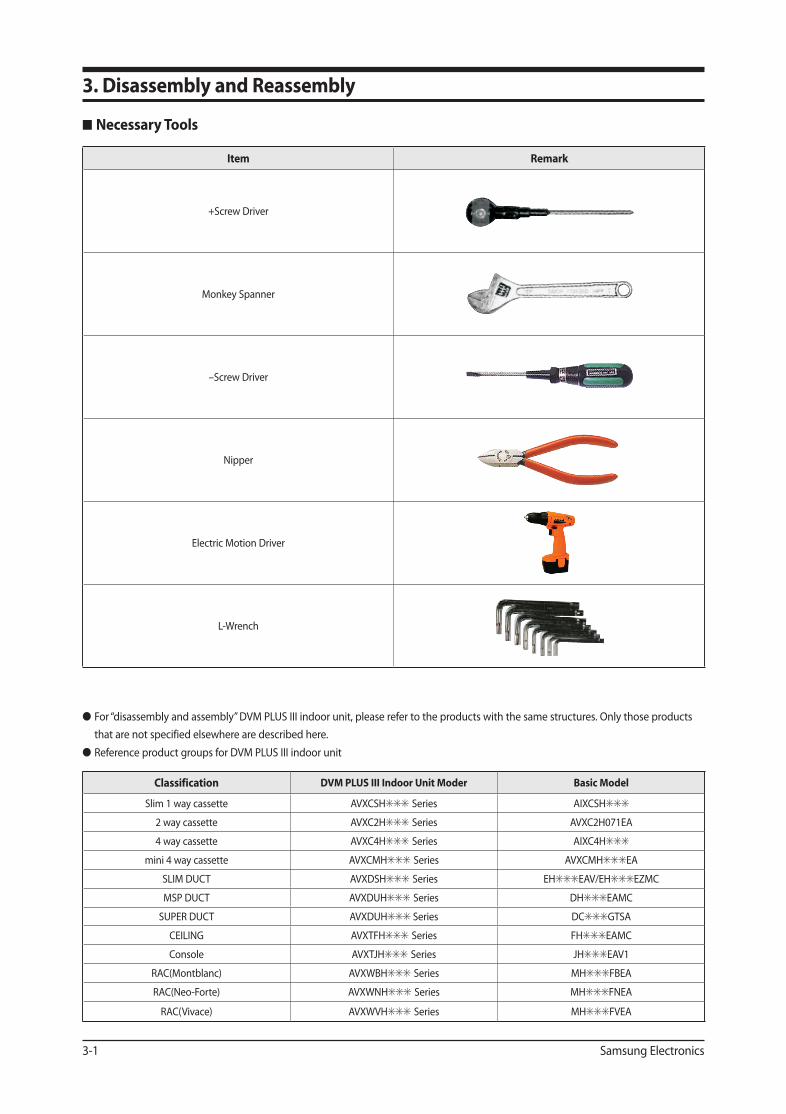
Necessary Tools
3. Disassembly and Reassembly
Item Remark
+Screw Driver
Monkey Spanner
–Screw Driver
Nipper
Electric Motion Driver
L-Wrench
For “disassembly and assembly” DVM PLUS III indoor unit, please refer to the products with the same structures. Only those products that are not specified elsewhere are described here.
Reference product groups for DVM PLUS III indoor unit
Classification DVM PLUS III Indoor Unit Moder Basic Model
Slim 1 way cassette AVXCSHSeries AIXCSH
2 way cassette AVXC2HSeries AVXC2H071EA
4 way cassette AVXC4HSeries AIXC4H
mini 4 way cassette AVXCMHSeries AVXCMHEA
SLIM DUCT AVXDSHSeries EHEAV/EHEZMC
MSP DUCT AVXDUHSeries DHEAMC
SUPER DUCT AVXDUH Series DCGTSA
CEILING AVXTFHSeries FHEAMC
Console AVXTJHSeries JHEAV1
RAC(Montblanc) AVXWBHSeries MHFBEA
RAC(Neo-Forte) AVXWNHSeries MHFNEA
RAC(Vivace) AVXWVHSeries MHFVEA
AVXCSH022_29550A(5)_1~3.indd 1 2009-11-06 ソタタ・11:36:22
Samsung Electronics 3-2
No Parts Procedure Remark
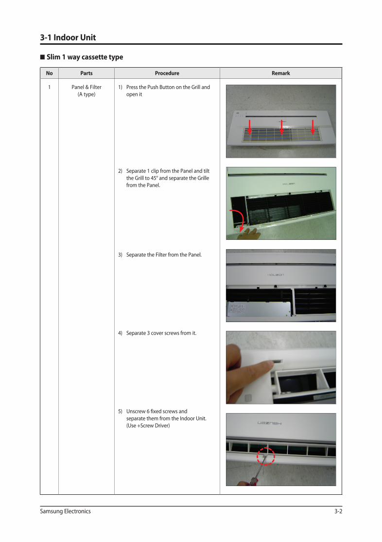
1 Panel & Filter(A type)
1) Press the Push Button on the Grill and open it
2) Separate 1 clip from the Panel and tilt the Grill to 45° and separate the Grille from the Panel.
3) Separate the Filter from the Panel.
4) Separate 3 cover screws from it.
5) Unscrew 6 fixed screws and separate them from the Indoor Unit. (Use +Screw Driver)
3-1 Indoor Unit
Slim 1 way cassette type
AVXCSH022_29550A(5)_1~3.indd 2 2009-11-06 ソタタ・11:36:22
Disassembly and Reassembly
3-3 Samsung Electronics
No Parts Procedure Remark
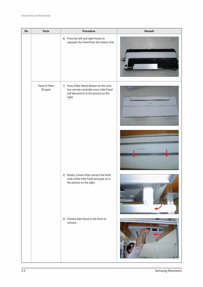
6) Press the left and right Hooks to separate the Panel from the Indoor Unit.
Panel & Filter(B type)
1) Press [Filter Reset] Button on the wire-less remote controller once. Inlet Panel will descend as in the picture on the right.
2) Rotate 2 levers that connect the both ends of the Inlet Panel and gear as in the picture on the right.
3) Pull the Inlet Panel to the front to remove.
AVXCSH022_29550A(5)_1~3.indd 3 2009-11-06 ソタタ・11:36:22
Disassembly and Reassembly
Samsung Electronics 3-4
No Parts Procedure Remark
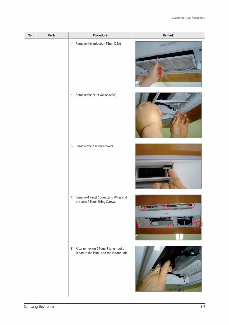
4) Remove the induction Filter. (2EA)
5) Remove the Filter Guide. (2EA)
6) Remove the 3 screws covers.
7) Remove 4 Panel Connecting Wires and unscrew 7 Panel fixing Screws.
8) After removing 2 Panel Fixing hooks, separate the Panel and the Indoor unit.
AVXCSH022_29550A(5)_1~3.indd 4 2009-11-06 ソタタ・11:36:23
Disassembly and Reassembly
3-5 Samsung Electronics
No Parts Procedure Remark
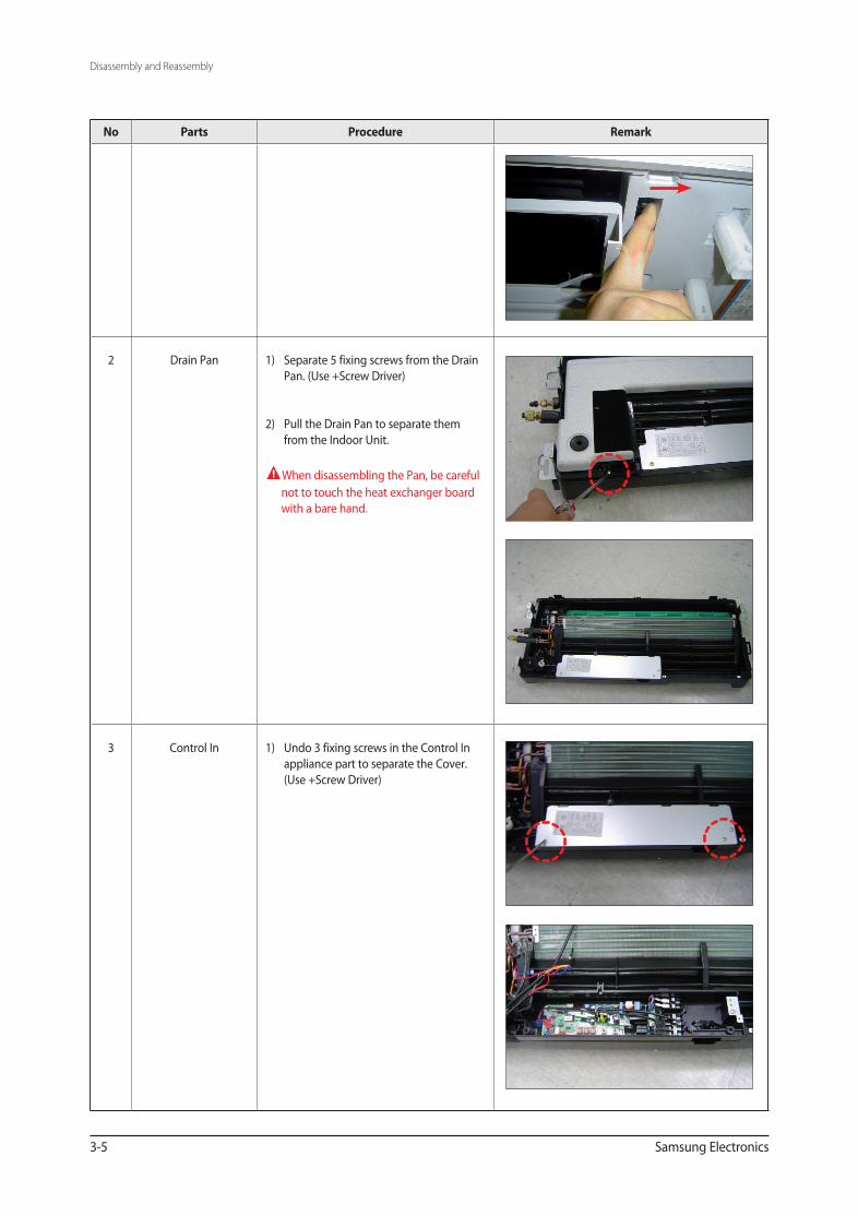
2 Drain Pan 1) Separate 5 fixing screws from the Drain Pan. (Use +Screw Driver)
2) Pull the Drain Pan to separate them from the Indoor Unit.
When disassembling the Pan, be careful not to touch the heat exchanger board with a bare hand.
3 Control In 1) Undo 3 fixing screws in the Control In appliance part to separate the Cover. (Use +Screw Driver)
AVXCSH022_29550A(5)_1~3.indd 5 2009-11-06 ソタタ・11:36:23
Disassembly and Reassembly
Samsung Electronics 3-6
No Parts Procedure Remark
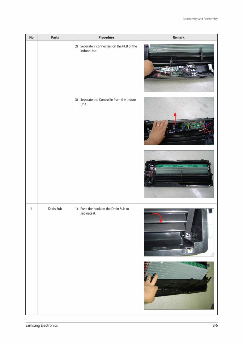
2) Separate 8 connecters on the PCB of the Indoor Unit.
3) Separate the Control In from the Indoor Unit.
4 Drain Sub 1) Push the hook on the Drain Sub to separate it.
AVXCSH022_29550A(5)_1~3.indd 6 2009-11-06 ソタタ・11:36:23
Disassembly and Reassembly
3-7 Samsung Electronics
No Parts Procedure Remark
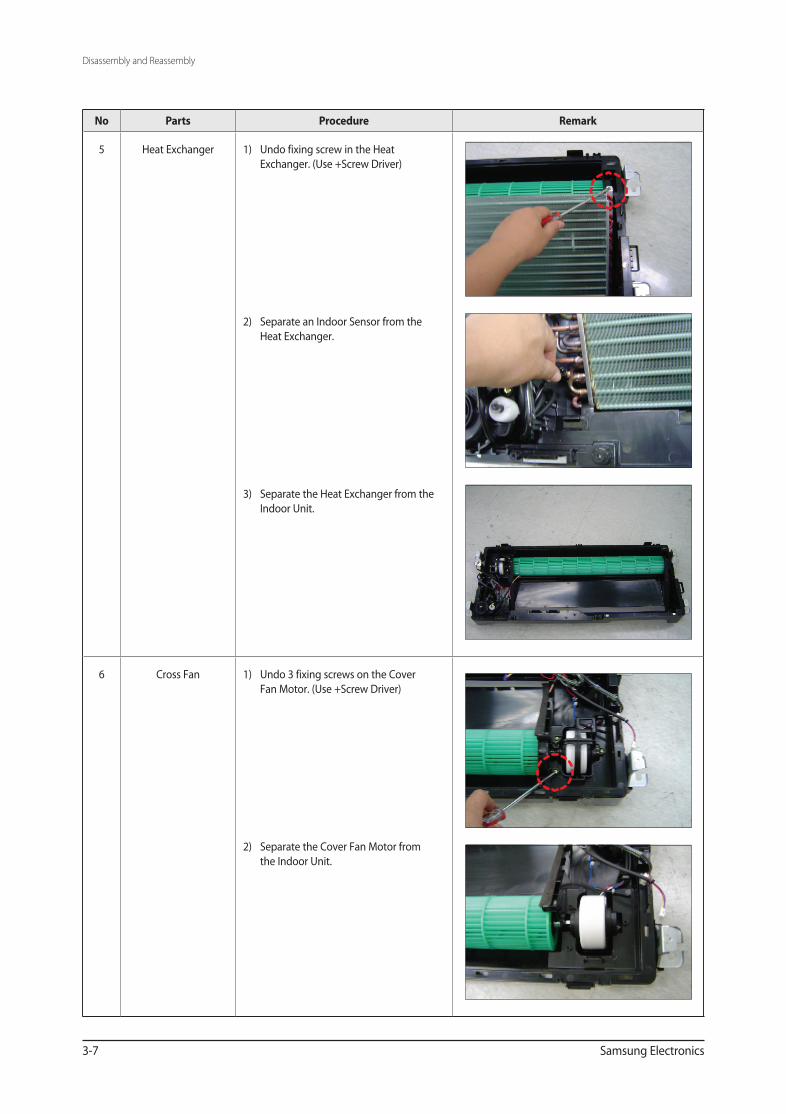
5 Heat Exchanger 1) Undo fixing screw in the Heat Exchanger. (Use +Screw Driver)
2) Separate an Indoor Sensor from the Heat Exchanger.
3) Separate the Heat Exchanger from the Indoor Unit.
6 Cross Fan 1) Undo 3 fixing screws on the Cover Fan Motor. (Use +Screw Driver)
2) Separate the Cover Fan Motor from the Indoor Unit.
AVXCSH022_29550A(5)_1~3.indd 7 2009-11-06 ソタタ・11:36:23
Disassembly and Reassembly
Samsung Electronics 3-8
No Parts Procedure Remark
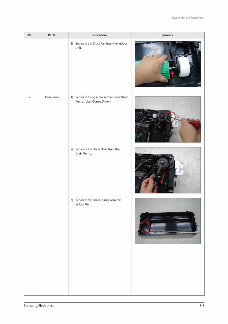
3) Separate the Cross Fan from the Indoor Unit.
7 Drain Pump 1) Separate fixing screw in the Cover Drain Pump. (Use +Screw Driver)
2) Separate the Drain Hose from the Drain Pump.
3) Separate the Drain Pump from the Indoor Unit.
AVXCSH022_29550A(5)_1~3.indd 8 2009-11-06 ソタタ・11:36:24
3-9 Samsung Electronics
No Parts Procedure Remark
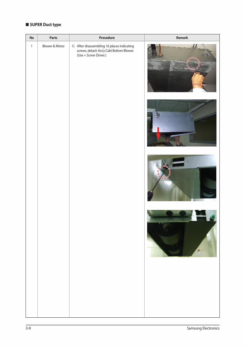
1 Blower & Motor 1) After disassembling 16 places indicating screws, detach Ass'y Cabi Bottom Blower. (Use + Screw Driver.)
SUPER Duct type
AVXCSH022_29550A(5)_1~3.indd 9 2009-11-06 ソタタ・11:36:24
Disassembly and Reassembly
Samsung Electronics 3-10
No Parts Procedure Remark
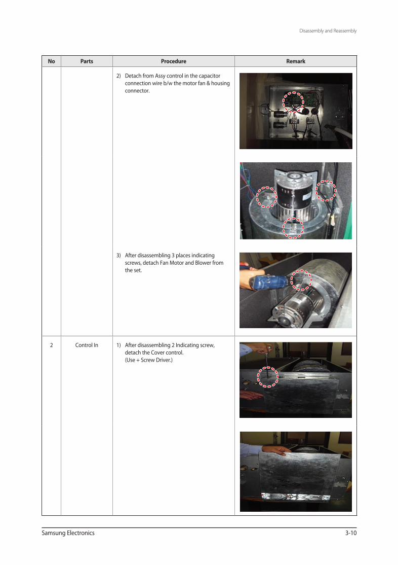
2) Detach from Assy control in the capacitor connection wire b/w the motor fan & housing connector.
3) After disassembling 3 places indicating screws, detach Fan Motor and Blower from the set.
2 Control In 1) After disassembling 2 Indicating screw, detach the Cover control. (Use + Screw Driver.)
AVXCSH022_29550A(5)_1~3.indd 10 2009-11-06 ソタタ・11:36:25
Disassembly and Reassembly
3-11 Samsung Electronics
No Parts Procedure Remark
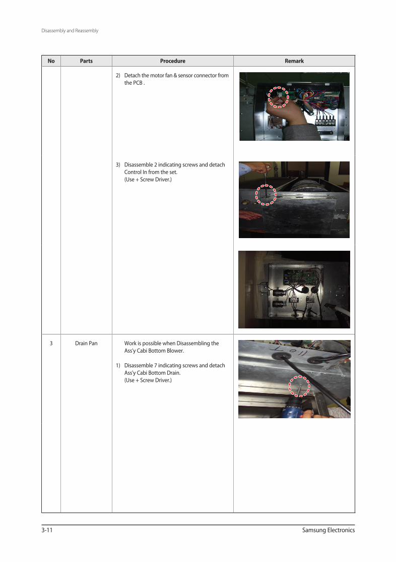
2) Detach the motor fan & sensor connector from the PCB .
3) Disassemble 2 indicating screws and detach Control In from the set. (Use + Screw Driver.)
3 Drain Pan Work is possible when Disassembling the Ass'y Cabi Bottom Blower. 1) Disassemble 7 indicating screws and detach Ass'y Cabi Bottom Drain. (Use + Screw Driver.)
AVXCSH022_29550A(5)_1~3.indd 11 2009-11-06 ソタタ・11:36:25
Disassembly and Reassembly
Samsung Electronics 3-12
No Parts Procedure Remark
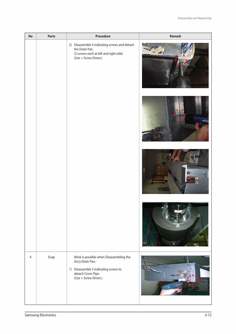
2) Disassemble 4 indicating screws and detach the Drain Pan. (2 screws each at left and right side) (Use + Screw Driver.)
4 Evap Work is possible when Disassembling the Ass'y Drain Pan.
1) Disassemble 5 indicating screws to detach Cover Pipe. (Use + Screw Driver.)
AVXCSH022_29550A(5)_1~3.indd 12 2009-11-06 ソタタ・11:36:25
Disassembly and Reassembly
3-13 Samsung Electronics
No Parts Procedure Remark
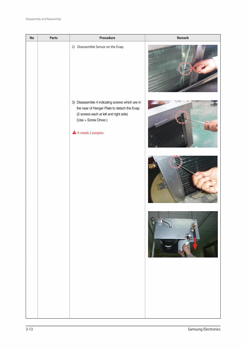
2) Disassemble Sensor on the Evap.
3) Disassemble 4 indicating screws which are in
the near of Hanger Plate to detach the Evap.
(2 screws each at left and right side)
(Use + Screw Driver.)
It needs 2 peoples.
AVXCSH022_29550A(5)_1~3.indd 13 2009-11-06 ソタタ・11:36:26
Samsung Electronics 3-14
No Parts Procedure Remark
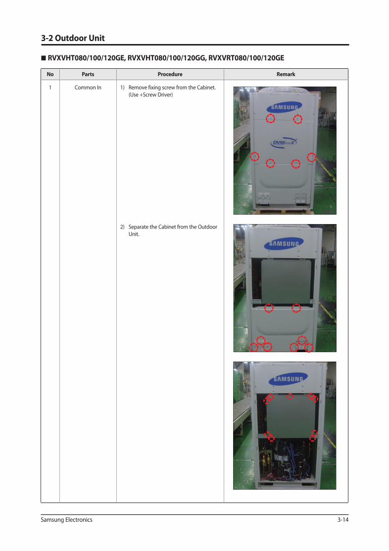
1 Common In 1) Remove fixing screw from the Cabinet. (Use +Screw Driver)
2) Separate the Cabinet from the Outdoor Unit.
3-2 Outdoor Unit
RVXVHT080/100/120GE, RVXVHT080/100/120GG, RVXVRT080/100/120GE
AVXCSH022_29550A(5)_1~3.indd 14 2009-11-06 ソタタ・11:36:26
3-15 Samsung Electronics
No Parts Procedure Remark
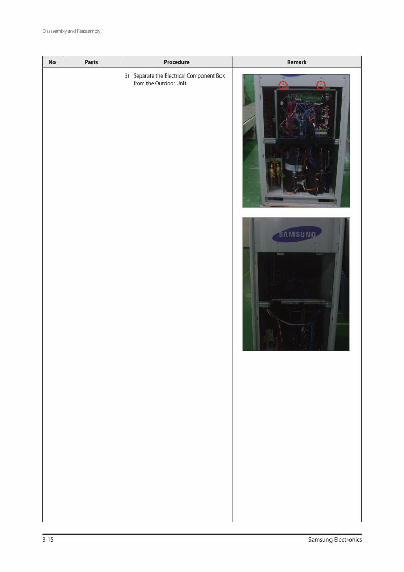
3) Separate the Electrical Component Box from the Outdoor Unit.
Disassembly and Reassembly
AVXCSH022_29550A(5)_1~3.indd 15 2009-11-06 ソタタ・11:36:26
Samsung Electronics 3-16
No Parts Procedure Remark
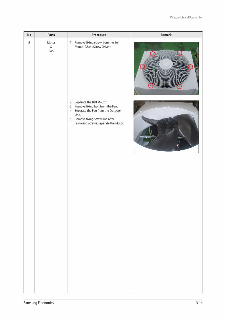
2 Motor&
Fan
1) Remove fixing screw from the Bell Mouth. (Use +Screw Driver)
2) Separate the Bell Mouth.3) Remove fixing bolt from the Fan.4) Separate the Fan from the Outdoor
Unit.5) Remove fixing screw and after
removing screws, separate the Motor.
Disassembly and Reassembly
AVXCSH022_29550A(5)_1~3.indd 16 2009-11-06 ソタタ・11:36:26
Disassembly and Reassembly
3-17 Samsung Electronics
RVXVHT140/160GE, RVXVHT140/160GG, RVXVRT140/160GE
No Parts Procedure Remark
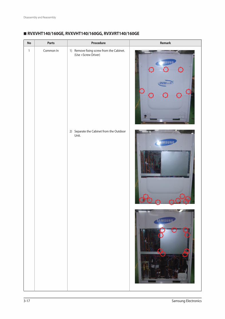
1 Common In 1) Remove fixing screw from the Cabinet. (Use +Screw Driver)
2) Separate the Cabinet from the Outdoor Unit.
AVXCSH022_29550A(5)_1~3.indd 17 2009-11-06 ソタタ・11:36:27
Disassembly and Reassembly
Samsung Electronics 3-18
No Parts Procedure Remark
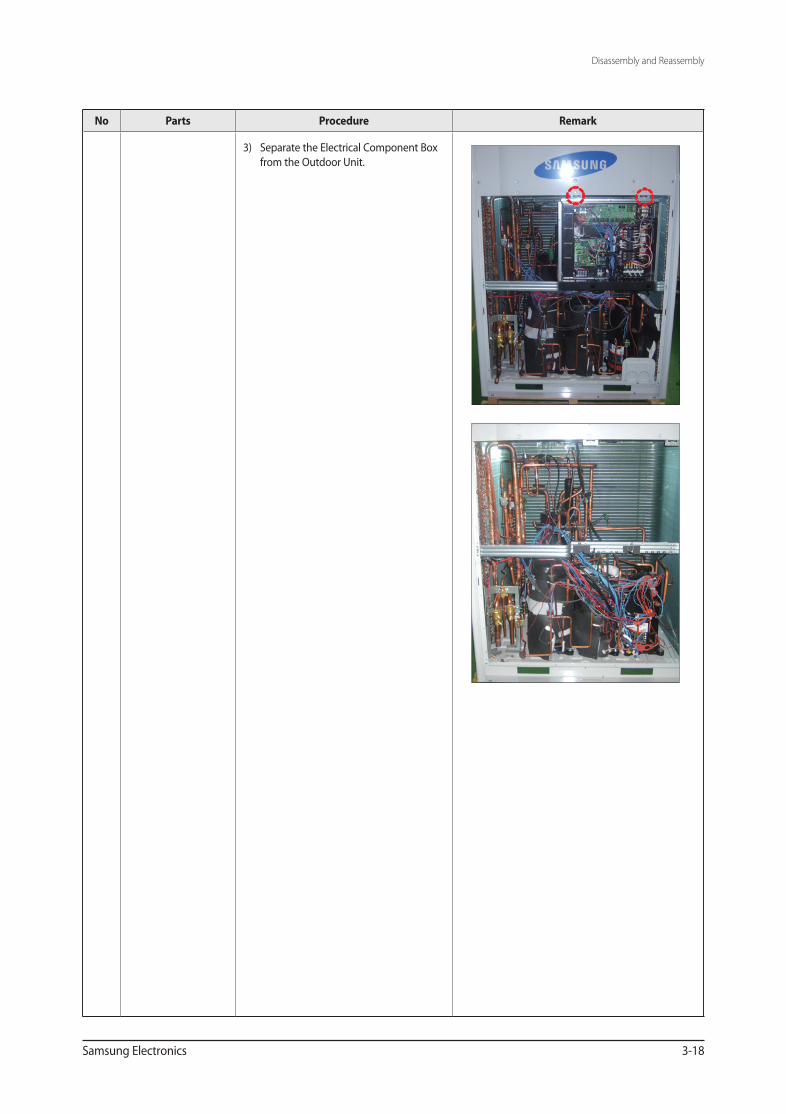
3) Separate the Electrical Component Box from the Outdoor Unit.
AVXCSH022_29550A(5)_1~3.indd 18 2009-11-06 ソタタ・11:36:27
Disassembly and Reassembly
3-19 Samsung Electronics
No Parts Procedure Remark
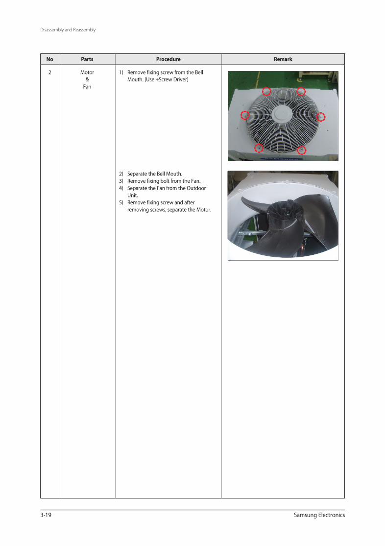
2 Motor&
Fan
1) Remove fixing screw from the Bell Mouth. (Use +Screw Driver)
2) Separate the Bell Mouth.3) Remove fixing bolt from the Fan.4) Separate the Fan from the Outdoor
Unit.5) Remove fixing screw and after
removing screws, separate the Motor.
AVXCSH022_29550A(5)_1~3.indd 19 2009-11-06 ソタタ・11:36:27
Related Documents