WBI-PRINT 5 WBI GmbH, Henricistr. 50, 52072 Aachen, Germany www.wbionline.de - 67- 3. Crown heading with open invert 3.1 Glockenberg Tunnel near Koblenz, Germany 3.1.1 Introduction In the course of the improvement of the federal highway 42 (B 42) between Bendorf and Lahnstein, Germany, the Glockenberg Tunnel was constructed on the side of the Rhine river opposite to the city of Koblenz. This tunnel enables a non-intersecting access from the B 42 to the Pfaffendorf Rhine bridge. The southern portal of the tunnel lies in the direct extension of the Pfaffendorf Bridge. For each direc- tion, the tunnel includes one driving lane, one stopping lane and an emergency sidewalk. In the mountain, the tunnel axis performs a 180° turn with a radius of ca. 50 m and then branches out into two single-lane tunnel tubes. One of these tubes accesses the B 42 in the direction of Bendorf, while the other one enables exiting the B 42 coming from Lahnstein into the direction of Koblenz (Fig. 3.1). Fig. 3.1: Glockenberg Tunnel, site plan with analysis cross- sections

Welcome message from author
This document is posted to help you gain knowledge. Please leave a comment to let me know what you think about it! Share it to your friends and learn new things together.
Transcript

WBI-PRINT 5 WBI GmbH, Henricistr. 50, 52072 Aachen, Germany www.wbionline.de
- 67 -
3. Crown heading with open invert
3.1 Glockenberg Tunnel near Koblenz, Germany
3.1.1 Introduction
In the course of the improvement of the federal highway 42 (B 42)between Bendorf and Lahnstein, Germany, the Glockenberg Tunnel wasconstructed on the side of the Rhine river opposite to the city ofKoblenz.
This tunnel enables a non-intersecting access from the B 42 to thePfaffendorf Rhine bridge. The southern portal of the tunnel liesin the direct extension of the Pfaffendorf Bridge. For each direc-tion, the tunnel includes one driving lane, one stopping lane andan emergency sidewalk. In the mountain, the tunnel axis performs a180° turn with a radius of ca. 50 m and then branches out into twosingle-lane tunnel tubes. One of these tubes accesses the B 42 inthe direction of Bendorf, while the other one enables exiting theB 42 coming from Lahnstein into the direction of Koblenz (Fig.3.1).
Fig. 3.1: Glockenberg Tunnel, site plan with analysis cross-sections
WBI-PRINT 5 WBI GmbH, Henricistr. 50, 52072 Aachen, Germany www.wbionline.de
- 68 -
3.1.2 Structure
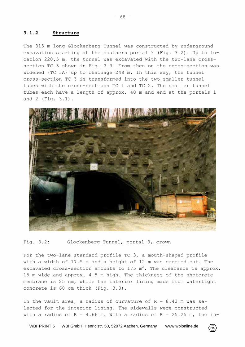
The 315 m long Glockenberg Tunnel was constructed by undergroundexcavation starting at the southern portal 3 (Fig. 3.2). Up to lo-cation 220.5 m, the tunnel was excavated with the two-lane cross-section TC 3 shown in Fig. 3.3. From then on the cross-section waswidened (TC 3A) up to chainage 248 m. In this way, the tunnelcross-section TC 3 is transformed into the two smaller tunneltubes with the cross-sections TC 1 and TC 2. The smaller tunneltubes each have a length of approx. 40 m and end at the portals 1and 2 (Fig. 3.1).
Fig. 3.2: Glockenberg Tunnel, portal 3, crown
For the two-lane standard profile TC 3, a mouth-shaped profilewith a width of 17.5 m and a height of 12 m was carried out. Theexcavated cross-section amounts to 175 m2. The clearance is approx.15 m wide and approx. 4.5 m high. The thickness of the shotcretemembrane is 25 cm, while the interior lining made from watertightconcrete is 60 cm thick (Fig. 3.3).
In the vault area, a radius of curvature of R = 8.43 m was se-lected for the interior lining. The sidewalls were constructedwith a radius of R = 4.66 m. With a radius of R = 25.25 m, the in-

WBI-PRINT 5 WBI GmbH, Henricistr. 50, 52072 Aachen, Germany www.wbionline.de
- 69 -
vert was only slightly rounded out. For the transition from thesidewalls to the invert, a radius of R = 2.66 m was selected (Fig.3.3).
Fig. 3.3: Glockenberg Tunnel, tunnel cross-section TC 3
Fig. 3.4 shows the vertical section through the tunnel axis in thearea of tunnel cross-sections TC3 and TC3A as a development. Themaximum overburden height amounts to approx. 50 m.

WBI-PRINT 5 WBI GmbH, Henricistr. 50, 52072 Aachen, Germany www.wbionline.de
- 70 -
Fig. 3.4: Glockenberg Tunnel, vertical section through thetunnel axis, development

WBI-PRINT 5 WBI GmbH, Henricistr. 50, 52072 Aachen, Germany www.wbionline.de
- 71 -
3.1.3 Ground and groundwater conditions
The ground along the alignment of the Glockenberg tunnel was ex-plored using core drillings and test pits. One borehole wasequipped as an observation well (Fig. 3.4).
According to the exploration, an up to 9 m thick soil layer con-sisting of talus material, residual detritus, loess and loess loamis underlain by an alternating sequence of slate and fine- to me-dium-grained sandstones belonging stratigraphically to the LowerDevonian of the Emsian stage (Fig. 3.4).
In the course of the Variscan orogenesis phase, the originallyhorizontal strata series were narrowed in NW-SE direction and bentto folds of different sizes. Within the large-scale folding struc-ture, the alternating sequence of ribboned or flaser-like, locallysecondarily silicated slates with sandstone banks up to severalmeters thick is in parts specially folded and sheared.
The sandstones are mostly quartzitically, locally also calcare-ously and ferrugineously cemented. Quartz and calcite veins milli-meters to centimeters thick often occur in the rock zones rich insand.
According to the results of the petrographic microscopy and X-raydiffractometry investigations, quartz, feldspar, mica and carbon-ates are the main rock-forming components.
The tunnel area is characterized by a distinct tectonic deforma-tion in the form of a "special folding". Shallow as well as steepdipping of the strata to the northwest and southeast, respec-tively, occurs here with changes taking place over very short dis-tances.
The rock is fractured by bedding-parallel discontinuities, the fo-liation and joints. As a result of the folding structure, the ori-entation of the discontinuities varies within the tunnel area.Fig. 3.5 shows the mean discontinuity orientations measured onoriented drill cores.

WBI-PRINT 5 WBI GmbH, Henricistr. 50, 52072 Aachen, Germany www.wbionline.de
- 72 -
Fig. 3.5: Glockenberg Tunnel, site plan showing the orienta-tion of the discontinuities and the location of theexpected fault zones
As far as it can be assessed from the surface exposures, the bed-ding-parallel discontinuities must be assumed completely sepa-rated. Due to the exceeding of the shear strength on the bedding-parallel discontinuities as a result of shear during folding,triturated material and slickenside lineations locally exist onthese planes. The same applies to quartz and calcite segregationswhich deposited in the cracks that developed due to dilatancy dur-ing the folding process.
Judging from surface exposures in the surroundings of the tunnel,the extension and the spacing of the foliation discontinuities de-pend distinctly on the appearance of the intact rock. In the caseof greater thickness of the banks and mostly in the clayey rock

WBI-PRINT 5 WBI GmbH, Henricistr. 50, 52072 Aachen, Germany www.wbionline.de
- 73 -
zones, individual completely separated foliation parallel discon-tinuities exist. Locally also slickenside lineations and tritu-rated material were found on the foliation parallel discontinui-ties, indicating tectonic loading.
The joints contain many more rock bridges than the bedding- andfoliation parallel discontinuities. Their degree of separation iscorrespondingly smaller.
In some core drillings, locally an increased core fragmentation, amore frequent appearance of slickensides parallel to the beddingor to the foliation, numerous quartz and calcite veins as well asrather strongly disintegrated rock zones were encountered. Thisled to the assumption that a fault zone striking in NE-SW direc-tion in the area of tunnel cross-section TC 3 may be present (Fig.3.5). Another fault zone was assumed in the area of tunnel cross-section TC 2 on the basis of the exploration results (Fig. 3.5).
Beneath the soil cover, which was encountered down to a depth of 9m below ground surface during the exploration as mentioned above,the rock has only slightly been altered by weathering processes.An exception are more strongly fragmented rock zones, e. g. faultzones, in which weathering has clearly progressed.
To investigate the hydrological conditions, the groundwater levelin the observation well OW (see Fig. 3.4) was measured and perme-ability tests were carried out at different depths in the bore-holes.
The observation well was set up in the area in which the highestgroundwater level was expected due to the location on the slope.The measurements showed that the groundwater is encountered hereapprox. 1 m above the tunnel roof (see Fig. 3.4).
3.1.4 Excavation classes
Because of the size of the excavated cross-section of approx.175 m2 (see Fig. 3.3), it was necessary to carry out excavation andsupport separately for crown, bench and invert (Fig. 3.6).

WBI-PRINT 5 WBI GmbH, Henricistr. 50, 52072 Aachen, Germany www.wbionline.de
- 74 -
Fig. 3.6: Excavation classes 4, 5 and 6A for tunnel cross-section TC 3 (final design)
As already mentioned, a uniform orientation of the discontinuitiescould not be assumed. In addition, due to the circular tunnel

WBI-PRINT 5 WBI GmbH, Henricistr. 50, 52072 Aachen, Germany www.wbionline.de
- 75 -
alignment, the orientation of the discontinuities relative to thetunnel axis changed continuously with the heading. Further, faultzones locally had to be expected (see Fig. 3.5). Therefore fre-quently varying rock conditions were assumed for the tender designand the final design. Correspondingly, the excavation classes 4,5, 6A and 7A were specified in the final design in accordance withthe recommendations of the working group "Tunneling" of the GermanGeotechnical Society (DGGT, 1995: Table 1).
A crown heading with an open invert was planned. The excavationclass as well as the trailing distances of the bench excavationand the closing of the invert lining (E and F in Fig. 3.6) were tobe selected in the course of the crown heading on the basis of theresults of mapping and monitoring during construction (see Chapter3.1.6). In this context special emphasis was placed on the resultsof the stability analyses (see Chapter 3.1.5) and of the geotech-nical mapping.
The excavation methods, round lengths and support measures speci-fied for the excavation classes 4, 5 and 6A for tunnel cross-section TC 3 in the final design are listed in Fig. 3.6. The exca-vation class 7A including advance support and support of the tun-nel face was not carried out during construction.
Heading was planned by smooth blasting and/or mechanical excava-tion by a tunnel excavator and hydraulic chisel.
The unsupported round length during crown heading was selected as2.0 m for excavation class 4 and 1.5 m for excavation classes 5and 6A. In excavation class 6A an advance support of the crownwith 4 to 5 m long mortar spiles was planned for every secondround. Excavation class 5 included a sealing of the temporarycrown face with shotcrete (Fig. 3.6).
For the shotcrete membrane, shotcrete of grade B25 with a thick-ness of 25 cm and two layers of reinforcing mats Q295 were speci-fied. In the crown area, a systematic anchoring with 7 SN-anchors(excavation classes 4 and 5) resp. 9 SN-anchors (excavation class6A) per round was planned. In each round a lattice girder was tobe installed in the crown area (Fig. 3.6).
Due to reasons of construction management, a continuous crownheading was aimed for. If a trailing bench and invert should be-

WBI-PRINT 5 WBI GmbH, Henricistr. 50, 52072 Aachen, Germany www.wbionline.de
- 76 -
come necessary for stability reasons, the maximum trailing dis-tance E resp. F should amount to two tunnel diameters D (Fig.3.6).
Unsupported round lengths for bench and invert of 4 m for excava-tion class 4 and 3 m for excavation classes 5 and 6A were planned.In the bench area, a systematic anchoring with 12 anchors (excava-tion classes 4 and 6A) resp. 10 anchors (excavation class 5) perround was specified. In each round one lattice girder was to beextended to the bench invert (Fig. 3.6).
The anchors were designed to be 4 to 6 m long in the crown as wellas in the bench for all excavation classes (Fig. 3.6). If faultzones had to be crossed, locally longer anchors were planned to beinstalled.
3.1.5 Stability analyses
In order to investigate the stability and to dimension the shot-crete membrane, two-dimensional FE-analyses were carried out usingthe program system FEST03 (Wittke, 2000). Fig. 3.1 shows theanalysis cross-sections AC 1, AC 2 and AC 3 investigated for thetunnel cross-section TC 3.
Because of the varying orientations of the discontinuities in thetunnel area and the changing direction of the tunnel axis due tothe circular plan of the tunnel, four idealized structural modelswere established. All of them assume that the discontinuitiesstrike parallel to the tunnel axis. They are thus on the conserva-tive side with respect to the stability and the support measuresensuing from the analyses (see Fig. 3.5 and 3.7). Further, the dipangles of the discontinuities were varied over wide ranges (Fig.3.7).
In model A, the bedding (B) and the foliation (F) are assumed dip-ping each at 45° perpendicular to the tunnel axis in opposite di-rections. In addition, a vertical joint set (J) striking parallelto the tunnel is taken into account. In model B the foliation isassumed dipping at 30° while the bedding dips at 60° in the oppo-site direction. Here as well an additional vertical joint set ex-ists. Model C includes a vertical bedding striking parallel to thetunnel and a horizontal foliation. Instead of the vertical beddingplanes, vertical joints are assumed in model D.

WBI-PRINT 5 WBI GmbH, Henricistr. 50, 52072 Aachen, Germany www.wbionline.de
- 77 -
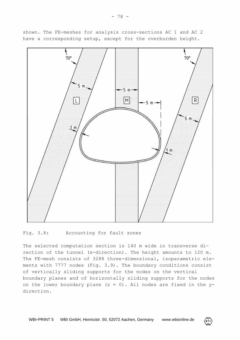
Aside from these different structural models, cases with a faultzone located in the area of the tunnel were investigated as well.Fig. 3.8 shows the assumed locations of these fault zones. Posi-tion L assumes a 5 m thick fault zone dipping at 70° close to theleft side of the tunnel. With position M a vertical, 5 m thickfault zone running through the tunnel cross-section is taken intoaccount. Position R assumes a 5 m thick fault zone dipping at 70°close to the right side of the tunnel.
Fig. 3.7: Considered structural models: a) Model A; b) modelB; c) model C; d) model D
In Fig. 3.9 and 3.10 the pseudo three-dimensional FE-mesh (slicewith thickness of 1 m) used for analysis cross-section AC 3 is
WBI-PRINT 5 WBI GmbH, Henricistr. 50, 52072 Aachen, Germany www.wbionline.de
- 78 -
shown. The FE-meshes for analysis cross-sections AC 1 and AC 2have a corresponding setup, except for the overburden height.
Fig. 3.8: Accounting for fault zones
The selected computation section is 140 m wide in transverse di-rection of the tunnel (x-direction). The height amounts to 120 m.The FE-mesh consists of 3288 three-dimensional, isoparametric ele-ments with 7777 nodes (Fig. 3.9). The boundary conditions consistof vertically sliding supports for the nodes on the verticalboundary planes and of horizontally sliding supports for the nodeson the lower boundary plane (z = 0). All nodes are fixed in the y-direction.

WBI-PRINT 5 WBI GmbH, Henricistr. 50, 52072 Aachen, Germany www.wbionline.de
- 79 -
Fig. 3.9: Analysis cross-section AC 3, FE-mesh, boundary con-ditions, ground profile and parameters (referencecase)
The setup of the ground layers is the same for all analysis cross-sections. The rock mass is encountered below a 5 m thick surfacesoil layer. In some analyses a fault zone in one of the positionsshown in Fig. 3.8 is modeled discretely.
The parameters assumed in the stability analyses for the soil andthe fault zone correspond to the specifications established during

WBI-PRINT 5 WBI GmbH, Henricistr. 50, 52072 Aachen, Germany www.wbionline.de
- 80 -
the tender design. The rock mechanical parameters were specifiedin accordance with the parties concerned.
Fig. 3.10: Analysis cross-section AC 3, FE-mesh, detail
For the reference case, Young's modulus of the rock mass was as-sumed conservatively as E = 1000 MN/m2. In comparative analyses avalue of 1500 MN/m2 was specified. Poisson's ratio was assumed as0.33 (Fig. 3.9).
The angles of friction on the bedding-parallel and foliation par-allel discontinuities were assumed as ϕb = ϕf = 24°. For the fric-tion angle on the joints a value of ϕj = 24° was selected (Fig.3.9).

WBI-PRINT 5 WBI GmbH, Henricistr. 50, 52072 Aachen, Germany www.wbionline.de
- 81 -
For the bedding parallel discontinuities no cohesion was assumedin all cases. The same applies to the foliation parallel disconti-nuities for the reference case (Fig. 3.9). In comparative analysesa cohesion of cf = 100 kN/m2 resp. cf = 200 kN/m2 was specified. Thecohesion on the joints was selected as cj = 150 kN/m2 in the refer-ence case (Fig. 3.9). In the comparative analyses it was assumedas cj = 200 kN/m2 and cj = 300 kN/m2, respectively.
The transfer of tensile stresses perpendicular to the discontinui-ties was excluded in all analysis cases.
A value of 15000 MN/m2 was specified as statically effectiveYoung's modulus of the shotcrete. This value is to include thehardening during the application of the load (see Chapter 2.1.5).As mentioned before, the thickness of the shotcrete membrane wasselected as t = 25 cm (Fig. 3.10, see also Fig. 3.3 and 3.6).
The analyses were based on elastic-viscoplastic stress-strain be-havior (Wittke, 2000) of the ground and elastic stress-strain be-havior of the shotcrete membrane.
According to the findings of the exploration, locally a ground wa-ter table lying above the tunnel roof had to be expected. With thedrainage during tunnel excavation, the ground water table is low-ered to the level of the tunnel invert. There was no water pres-sure therefore to be considered in the stability analyses for theshotcrete membrane.
Fig. 3.11 shows a schematic representation of the computationsteps for the simulation of the construction stages "crown excava-tion" and "bench excavation" and the excavation of the full cross-section.
The first computation step includes the computation of the stateof stress and deformation resulting from the dead weight of theground (in-situ state).
In the computation steps preceding the simulation of the individ-ual partial excavations (computation steps 2, 4 and 6), a preced-ing stress relief is accounted for in the respective cross-sectionarea to be excavated (Wittke, 2000).

WBI-PRINT 5 WBI GmbH, Henricistr. 50, 52072 Aachen, Germany www.wbionline.de
- 82 -
Fig. 3.11: Analysis cross-section AC 3, computation steps
WBI-PRINT 5 WBI GmbH, Henricistr. 50, 52072 Aachen, Germany www.wbionline.de
- 83 -
To this end, Young's modulus in this area is reduced to the valueEred = av · E where E denotes Young's modulus of the ground andav < 1.0 is the so-called stress-relief factor. The precedingstress relief enables an approximate representation of the defor-mations and stress redistributions occurring in the rock precedingthe tunnel excavation and the installation of the support. Due tothe preceding stress relief, the shotcrete membrane installed inthe following computation step is subjected to a smaller loadingcompared to a simultaneous simulation of excavation and installa-tion of the shotcrete support without the intermediate step of thepreceding stress relief. The stress relief factor is specified onthe basis of experience gained from measurements on completedstructures and comparisons with the results of three-dimensionalanalyses. In the present case, the preceding stress relief factorwas chosen as av = 0.5 (Fig. 3.11).
In addition to the installation of the shotcrete membrane, the in-stallation of the SN-anchors in crown and bench for excavationclass 6A (see Fig. 3.6) is simulated in computation steps 2 (crownexcavation and support) and 4 (bench excavation and support). Theanchors are modeled by 4 m long truss elements (Wittke, 2000; Fig.3.11).
In the following, the results of stability analyses for analysiscross-section AC 3 (see Fig. 3.1, 3.9 and 3.10) are shown exem-plarily.
Analysis cross-section AC 3 is located in the area of the maximumoverburden of approx. 50 m (Fig. 3.9). In this area the occurringdiscontinuity orientations can be captured approximately withstructural models B and C (see Fig. 3.7).
The construction stage after the bench excavation (5th computationstep) proves to be critical with respect to the stability of thetunnel, if structural model B and the parameters given in Fig. 3.9are assumed. If the anchors are not taken into account, the dis-placements do not converge in the course of the viscoplastic it-erative calculation in the 5th computation step, i. e. the stabi-lity of the tunnel cannot be proven by the analysis for this con-struction stage. Even if the anchors are taken into account, con-siderable viscoplastic displacements still result in this computa-tion step, especially at the left bench lining toe. These dis-placements converge, however, in the course of the viscoplastic

WBI-PRINT 5 WBI GmbH, Henricistr. 50, 52072 Aachen, Germany www.wbionline.de
- 84 -
iterative calculation. Fig. 3.12 and 3.13 show the principal nor-mal stresses, the areas where the shear strength on the disconti-nuities is exceeded and the displacements of the excavation pro-file computed for the bench excavation with the anchors taken intoaccount. The computed roof subsidence amounts to approx. 40 mm,the maximum heave of the invert to approx. 65 mm (Fig. 3.13).
Fig. 3.12: Analysis cross-section AC 3 (structural model B),principal normal stresses and exceeding of strength,bench excavation (5th computation step)
If structural model C is assumed, the stability of the tunnel canbe proven in the analysis for all construction stages even if thesystematic anchoring is not taken into account. Also, if a greater

WBI-PRINT 5 WBI GmbH, Henricistr. 50, 52072 Aachen, Germany www.wbionline.de
- 85 -
shear strength is assumed on the discontinuities, the computeddisplacements become considerably smaller.
Fig. 3.13: Analysis cross-section AC 3 (structural model B),displacements, bench excavation (5th – 1st computa-tion step)
Fig. 3.14 shows the bending moments and normal thrust in the shot-crete membrane calculated for the 5th computation step. For asafety factor of 1.35, the design results in a statically requiredreinforcement of up to 4.0 cm2/m. If the lattice girders are takeninto account, this reinforcement is covered by the planned rein-forcement (see Fig. 3.6).
Fig. 3.14: Analysis cross-section AC 3 (structural model B),stress resultants in the shotcrete membrane, benchexcavation (5th computation step)
In Fig. 3.15 the tensile anchor forces computed for the truss ele-ments for the 7th computation step are shown. They reach a maximumvalue of approx. 130 kN.

WBI-PRINT 5 WBI GmbH, Henricistr. 50, 52072 Aachen, Germany www.wbionline.de
- 86 -
Fig. 3.15: Analysis cross-section AC 3 (structural model B),tensile anchor forces, 7th computation step
The admissable anchor force of the installed anchors adm FA resultsfrom comparing the anchor force divided by the cross sectionalarea As with the tension yield point of the anchor steel βs takinginto account a factor of safety of η = 1.75. SN-anchors made fromBSt 500S (βs = 500 N/mm2) with a diameter of 25 mm were selected(see Fig. 3.6). This leads to the admissable anchor force:
kN140A1
Fadm SSA =⋅β⋅η
= (3.1)
This value is not exceeded in the analysis (see Fig. 3.15).
With the computation of the anchor forces it must be taken intoaccount that the placement of the anchors is simulated simultane-ously with the excavation and the installation of the shotcretemembrane (see Fig. 3.11). Thus the anchor loads are overestimatedin the analyses, since in reality the anchors are placed after theinstallation of the shotcrete membrane. To neutralize this effect,a Young's modulus smaller than the one of steel was assumed forthe anchors in the analyses.

WBI-PRINT 5 WBI GmbH, Henricistr. 50, 52072 Aachen, Germany www.wbionline.de
- 87 -
Fig. 3.16: Analysis cross-section AC 3 (structural model B),fault zone to the left of the tunnel, principal nor-mal stresses and exceeding of strength, bench exca-vation (5th computation step)
Due to the uncertainties involved with this approach regarding thecomputed anchor forces and stress resultants of the shotcrete mem-brane, a comparative analysis was carried out, in which the shearresistance of the anchors was converted into an equivalent cohe-sion on the discontinuities. This cohesion was assumed within theanchored area (see Chapter 2.3.2). The results of this analysisconfirmed the reinforcement determined before and thus indirectlyalso the computed anchor forces.

WBI-PRINT 5 WBI GmbH, Henricistr. 50, 52072 Aachen, Germany www.wbionline.de
- 88 -
Fig. 3.16 to 3.19 show the results of an analysis based on the pa-rameters given in Fig. 3.9 and 3.10, structural model B and in ad-dition a 5 m thick fault zone dipping at 70° close to the leftside of the tunnel (see Fig. 3.8, position L). For these unfavor-able assumptions the stability of the construction stage after thebench excavation (5th computation step, see Fig. 3.11) can only beproved in the analysis, if in the area of the left half of thetunnel 10 to 15 m long IBO-bolts (see Chapter 2.3.1) reaching be-hind the fault zone into the undisturbed rock mass are simulatedby truss elements.
The principal normal stresses, the exceeding of strength and thedisplacements computed for this case for the 5th computation stepare shown in Fig. 3.16 and 3.17. If the long anchors are simu-lated, the displacements of the excavation profile are of the samemagnitude as for the corresponding case without a fault zone (seeFig. 3.13 and 3.17).
Fig. 3.17: Analysis cross-section AC 3 (structural model B),fault zone to the left of the tunnel, displacements,bench excavation (5th – 1st computation step)

WBI-PRINT 5 WBI GmbH, Henricistr. 50, 52072 Aachen, Germany www.wbionline.de
- 89 -
Fig. 3.18: Analysis cross-section AC 3 (structural model B),fault zone to the left of the tunnel, stress resul-tants of the shotcrete membrane, bench excavation(5th computation step)
Fig. 3.18 shows the bending moments and normal thrust in the shot-crete membrane determined for the 5th computation step. Compared tothe corresponding case without a fault zone, greater maximum bend-ing moments and smaller maximum normal thrusts occur in the shot-crete (see Fig. 3.14 and 3.18). For a safety factor of 1.35, thedesign results in a statically required reinforcement of up to6.2 cm2/m. If the lattice girders are taken into account, this re-inforcement is covered by the planned reinforcement as well.
Fig. 3.19: Analysis cross-section AC 3 (structural model B),fault zone to the left of the tunnel, tensile anchorforces, 7th computation step

WBI-PRINT 5 WBI GmbH, Henricistr. 50, 52072 Aachen, Germany www.wbionline.de
- 90 -
In Fig. 3.19 the tensile anchor forces computed for the truss ele-ments in the 7th computation step are given. Only the anchors run-ning through the fault zone are loaded. The maximum computed an-chor force amounts to 150 kN, which is only slightly more than theadmissible anchor load according to (3.1) of the planned IBO-rods(∅ 25 mm) of 140 kN.
3.1.6 Crown heading and monitoring results
Geotechnical mappings of the crown face were carried out in regu-lar intervals during the heading. Special emphasis was placed onrecording the properties, extent and orientation of the disconti-nuities (Fig. 3.20). No fault zones were encountered in the tunnelcross-section.
Further, in the area of tunnel cross-section TC 3 ca. 20 measuringcross-sections with gage bolts were installed to monitor the dis-placements caused by the heading. In tunnel cross-sections TC 1and TC 2 further measuring cross-sections were installed.
As already mentioned, the excavation classes were determined onthe basis of the results of the stability analyses as well as themappings and the displacement measurements. Fig. 3.21 shows exem-plarily the maximum roof subsidence measured during crown headingin the area of tunnel cross-sections TC 3 and TC 3A. With the ex-ception of one measurement in the portal area (δR = 16 mm), themeasured values range from 1 to 7 mm.
In the area of the three analysis cross-sections AC 1, AC 2 and AC3, the measured roof subsidence can be compared with the resultsof the stability analyses. With this comparison it must be takeninto account, however, that the displacements that occurred in themeasuring cross-sections already before the zero reading cannot bemeasured. Since the elastic part of the displacements mostly oc-curred before the zero reading, the measured roof subsidence δR canapproximately be compared with the viscoplastic part of the dis-placements computed for the roof vp
Rδ . It becomes apparent that inthe area of analysis cross-sections AC 2 and AC 3 the measureddisplacements are smaller than the viscoplastic parts of the dis-placements computed with no cohesion assumed on the foliation-parallel discontinuities (cf = 0, see Fig. 3.9).

WBI-PRINT 5 WBI GmbH, Henricistr. 50, 52072 Aachen, Germany www.wbionline.de
- 91 -
Fig. 3.20: Crown face, chainage 216.1 m, excavation class 5:a) Photograph; b) mapping

WBI-PRINT 5 WBI GmbH, Henricistr. 50, 52072 Aachen, Germany www.wbionline.de
- 92 -
Fig. 3.21: Crown heading, comparison of measured and computedroof subsidence, tunnel cross-sections TC 3 and TC3A

WBI-PRINT 5 WBI GmbH, Henricistr. 50, 52072 Aachen, Germany www.wbionline.de
- 93 -
If a value of cf = 100 kN/m2 is chosen for the cohesion on the fo-liation parallel discontinuities, the measured roof subsidencecorresponds to the computed viscoplastic part of the displace-ments. For analysis cross-section AC 1, cf = 0 yields good agree-ment of the measured roof subsidence with the computed viscoplas-tic part of the displacements (Fig. 3.21).
The results of the geotechnical mapping of the tunnel face and thedisplacements measured during the crown heading allowed in consid-eration of the results of the stability analyses the tunnel to bedriven with excavation classes 4, 5 and 6A (see Fig. 3.6). Excava-tion class 7A was not carried out. Further, it was possible to ex-cavate the crown over the entire tunnel length without simultane-ously trailing bench.
3.1.7 Conclusions
The Glockenberg Tunnel is located in an alternating sequence ofslates and sandstones characterized by a tectonic deformation dueto a "special folding". The strength and deformability of the rockmass is predominantly determined by the discontinuities (beddingparallel discontinuities, foliation parallel discontinuities andjoints). As a consequence of the folding structure, the orienta-tion of the discontinuities is not uniform. In addition, thestrike directions of the discontinuities with respect to the tun-nel axis vary due to the almost circular tunnel alignment. Faultzones had to be expected locally as well.
Therefore, different structural models had to be assumed for thestability analyses. The comparison of the displacements measuredduring tunneling with the values computed for the different casesallowed to optimize the support measures and to apply economicalexcavation classes. It became apparent that the analyses repre-sented an essential contribution to an economical construction ofthis tunnel.

WBI-PRINT 5 WBI GmbH, Henricistr. 50, 52072 Aachen, Germany www.wbionline.de
- 94 -
3.2 Gäubahn Tunnel in Stuttgart, Germany
3.2.1 Introduction
The Gäubahn Tunnel is part of the new construction of the federalhighway B 14 between the Schattenring intersection and the Süd-heimer Square providing a northern bypass of the city district ofVaihingen in Stuttgart, Germany. It undercrosses a railway line(Gäubahn) and buildings adjacent to the Rudolf-Sophien institu-tion. During the heading underneath the railway track railwaytraffic had to be maintained. Specific tunnel support measureswere therefore planned for this section.
3.2.2 Structure
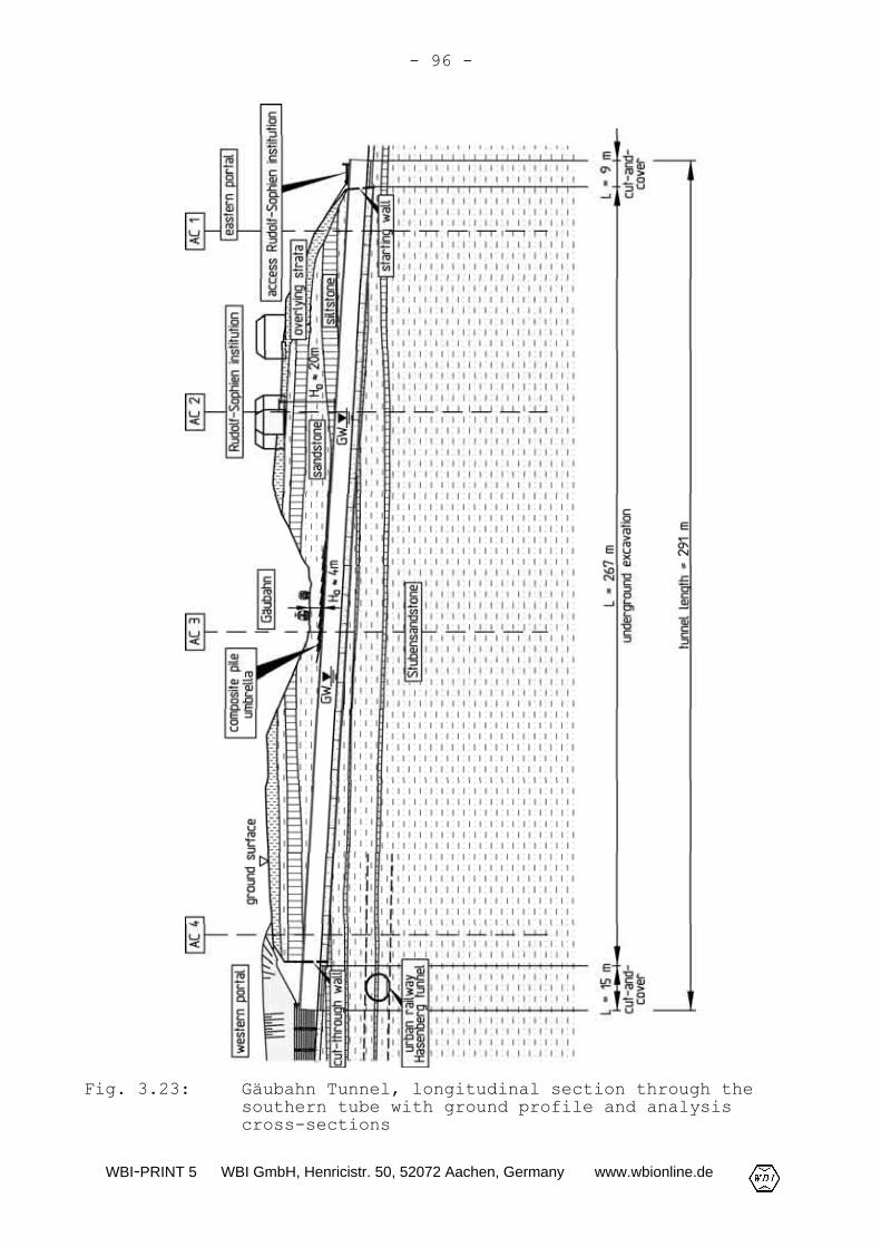
The Gäubahn Tunnel consists of two parallel ca. 300 m long tunneltubes with two lanes each (Fig. 3.22). Approx. 270 m of each tun-nel tube were driven by underground construction ascending fromthe eastern portal. The precuts in the portal areas were con-structed by the cut-and-cover method (Fig. 3.22 and 3.23).
The maximum overburden amounts to approx. 20 m. In the area of theundercrossing of the Gäubahn an overburden of approx. 4 m exists(Fig. 3.23).
Fig. 3.24 shows the 11.5 m wide and 8.85 m high standard profileof a tunnel tube. The excavated cross-section amounts to approx.93 m2. The shotcrete membrane has a concrete grade of B25 and athickness of 25 to 30 cm. The interior lining consists of water-tight grade B35 concrete with a thickness of 45 cm.
The roof and the invert are shallowly rounded with radii of curva-ture of R = 8.15 m and R = 10.45 m, respectively. At the sidewallsthe radius of curvature amounts to R = 5.45 m. The transitionsfrom the sidewalls to the roof and to the invert, respectively,were designed with comparatively small radii of R = 3.06 m andR = 2.65 m, respectively (Fig. 3.24).
The two tunnel tubes were constructed by advancing crown headingwith trailing bench and invert excavation. The cross-section iscorrespondingly divided into crown and bench/invert (Fig. 3.24).

WBI-PRINT 5 WBI GmbH, Henricistr. 50, 52072 Aachen, Germany www.wbionline.de
- 95 -
Fig. 3.22: Gäubahn Tunnel, site plan
WBI-PRINT 5 WBI GmbH, Henricistr. 50, 52072 Aachen, Germany www.wbionline.de
- 96 -
Fig. 3.23: Gäubahn Tunnel, longitudinal section through thesouthern tube with ground profile and analysiscross-sections

WBI-PRINT 5 WBI GmbH, Henricistr. 50, 52072 Aachen, Germany www.wbionline.de
- 97 -
Fig. 3.24: Gäubahn Tunnel, standard profile
Fig. 3.25 is an aerial photograph of the eastern precut with thebuildings of the Rudolf-Sophien institution after the excavationand support of both tunnel tubes. The picture shows the open-cutarch sections (cut-and-cover construction) in the transition fromunderground excavation to the portal blocks not yet built in therepresented construction phase.

WBI-PRINT 5 WBI GmbH, Henricistr. 50, 52072 Aachen, Germany www.wbionline.de
- 98 -
Fig. 3.25: Gäubahn Tunnel, eastern precut and Rudolf-Sophieninstitution
3.2.3 Ground and groundwater conditions
Below the ground surface a few meters thick overlying strata arepresent (Fig. 3.23). They consist mostly of rock weathered intosand and silt, respectively, and partially relocated.
The rock mass underneath belongs stratigraphically to the Stuben-sandstone formation consisting of a sequence of sandstones andsiltstones. The sandstone and siltstone layers are up to severalmeters thick. Locally, however, also narrowly spaced alternatingsequences occur (Fig. 3.23).
The sandstones as well as the siltstones are divided into banks bybedding planes. The thickness of these banks ranges between fewcentimeters and 1 to 2 m. The bedding planes are approximatelyhorizontal.
The joints are generally steeply dipping and deviate only littlefrom the direction perpendicular to the bedding (here: the verti-cal direction). In general they extend over many meters horizon-

WBI-PRINT 5 WBI GmbH, Henricistr. 50, 52072 Aachen, Germany www.wbionline.de
- 99 -
tally. At least in some areas the joints are slightly opened ac-cording to the exploration results.
In the siltstone layers slickensides were found as well in addi-tion to the bedding planes and joints. These slickensides are ran-domly oriented and have mostly smooth surfaces.
In the middle tunnel section two boreholes were equipped as obser-vation wells. According to their readings, the groundwater tablewas located at the level of the two tunnel cross-sections (Fig.3.23). In two observation wells located close to the tunnel por-tals no groundwater was encountered.
3.2.4 Excavation classes
The excavation of the two tunnel tubes was planned mostly as anadvancing crown heading with open invert and trailing bench andinvert excavation following excavation class 4A.
The excavation sequence, excavation method, round lengths and sup-port measures for excavation classes 4A-1, 4A-2 and 4A-3 (seeDGGT, 1995: Table 1) are given in Fig. 3.26. These excavationclasses differ with regard to in the unsupported round length, thelattice girder spacing and the number of anchors per round. Theshotcrete membrane is reinforced inside and outside with steelfabric mats Q295. If necessary, the tunnel face was planned to besealed with plain shotcrete. The trailing distance of bench (D)and invert (E) was to be determined depending on the monitoringresults and the geotechnical conditions encountered during theheading as well as depending on the results of the stabilityanalyses.
The tunnel was excavated using a tunnel excavator and, in some ar-eas, also by smooth blasting. Measurements carried out on build-ings showed that the vibration velocities remained far under thereference values for the admissible structural vibrations given inDIN 4150, part 3 (DIN 4150-3, 1999).

WBI-PRINT 5 WBI GmbH, Henricistr. 50, 52072 Aachen, Germany www.wbionline.de
- 100 -
Fig. 3.26: Standard heading, excavation classes 4A-1, 4A-2 and4A-3

WBI-PRINT 5 WBI GmbH, Henricistr. 50, 52072 Aachen, Germany www.wbionline.de
- 101 -
Fig. 3.27: Undercrossing of the Gäubahn, excavation classes6A-K and 7A-K: a) Cross-section; b) longitudinalsection (detail)
WBI-PRINT 5 WBI GmbH, Henricistr. 50, 52072 Aachen, Germany www.wbionline.de
- 102 -
In the area of the undercrossing of the Gäubahn a crown headingwith closed temporary invert with the excavation classes 6A-K and7A-K, respectively, was planned (see DGGT, 1995: Table 1) in orderto limit the tunneling-induced subsidence (Fig. 3.27). These exca-vation classes include an advancing support using so-called com-posite pile umbrellas. These consist of 8 m long piles with a di-ameter of 40 mm which were grouted in 116 mm boreholes using ce-ment based suspension and are slightly inclined against the hori-zontal in the longitudinal section (Fig. 3.23 and 3.27). In eachround one layer of composite piles (composite pile umbrella) wasconstructed. If required, spiles were planned to be installed inaddition. In excavation class 7A-K, the tunnel face was in addi-tion to be rounded out and supported with shotcrete (Fig. 3.27b).
3.2.5 Stability analyses for the design of the shotcretesupport
For the design of the shotcrete membrane, two-dimensional analyseswith the program system FEST03 (Wittke, 2000) were carried out.
The investigation comprised the analysis cross-sections AC 1 to AC4 shown in Fig. 3.23. Fig. 3.28 shows exemplarily the FE-mesh, theboundary conditions, the ground profile and the parameters usedfor analysis cross-section AC 2. Analysis cross-section AC 2 islocated in the area of the undercrossing of the buildings adjacentto the Rudolf-Sophien institution. The overburden in this areaamounts to approx. 20 m (see Fig. 3.23).
The 52 m wide, 66 m high and 1 m thick computation section in theform of a slice is discretized by an FE-mesh with 2703 iso-parametric elements and 13956 nodes. To simplify matters, only onetunnel tube is modeled. The plane of symmetry lies in the middleof the rock pillar between the two tunnel tubes. Thus the simulta-neous excavation of both tunnel tubes is simulated in the analy-ses. In reality, the crown excavation of one tunnel tube precedesthe other one. The simulation of a simultaneous heading of bothtubes however is on the safe side with regard to the loading ofthe rock mass and the stability of the openings. For the nodes ofthe vertical boundary planes vertically movable supports are in-troduced as boundary conditions, whereas for the nodes on thelower boundary plane (z = 0) horizontally movable supports arespecified (Fig. 3.28). All nodes are fixed in the y-direction.

WBI-PRINT 5 WBI GmbH, Henricistr. 50, 52072 Aachen, Germany www.wbionline.de
- 103 -
Fig. 3.28: Analysis cross-section AC 2, FE-mesh, boundary con-ditions, ground profile and parameters
Four sandstone and siltstone horizons each of the alternating se-quence of the Stubensandstone formation were modeled. The posi-tioning of the siltstone horizon in the roof area is to be as-sessed unfavorable with respect to the stability of the tunnel,
WBI-PRINT 5 WBI GmbH, Henricistr. 50, 52072 Aachen, Germany www.wbionline.de
- 104 -
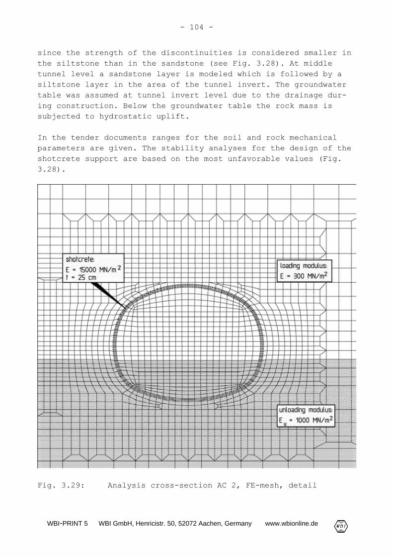
since the strength of the discontinuities is considered smaller inthe siltstone than in the sandstone (see Fig. 3.28). At middletunnel level a sandstone layer is modeled which is followed by asiltstone layer in the area of the tunnel invert. The groundwatertable was assumed at tunnel invert level due to the drainage dur-ing construction. Below the groundwater table the rock mass issubjected to hydrostatic uplift.
In the tender documents ranges for the soil and rock mechanicalparameters are given. The stability analyses for the design of theshotcrete support are based on the most unfavorable values (Fig.3.28).
Fig. 3.29: Analysis cross-section AC 2, FE-mesh, detail

WBI-PRINT 5 WBI GmbH, Henricistr. 50, 52072 Aachen, Germany www.wbionline.de
- 105 -
The intact rock strength of the sand- and siltstones was assumedinfinitely high as a simplification. The rock matrix was assignedelastic stress-deformation behavior. This simplification is justi-fied, because the strength on the discontinuities is markedlysmaller than the intact rock strength. Two discontinuity sets weretaken into account in the analyses. The horizontal bedding and avertical joint set striking parallel to the tunnel axis with anunfavorable effect on tunnel stability.
At and underneath the tunnel invert, the rock mass is unloadedduring the tunnel excavation. Previous experience has shown thatthe modulus relevant for the unloading of the rock mass is higherthan the loading modulus assumed as E = 300 MN/m2. Correspondingly,the elements in and underneath the invert area were assigned anunloading modulus of EU = 1000 MN/m2 (see Fig. 3.29).
The statically effective Young's modulus of the shotcrete wasspecified as 15000 MN/m2 taking into account the hardening duringthe application of the load (Fig. 3.29).
The excavation and support of the tunnel were simulated in fivecomputation steps (Fig. 3.30). The first computation step com-prises the determination of the state of stress and deformationresulting from the dead weight of the ground (in-situ state). Withcomputation steps 2 and 3 the crown excavation and its support us-ing shotcrete are simulated. To this end, Young's modulus of theelements in the crown was reduced in the 2nd computation step tothe value Ered = av · E with av = 0.5. av is the so-called stressrelief factor already mentioned in Chapter 3.1 (Wittke, 2000). Theexcavation and support of the crown follow in the 3rd computationstep. In the 4th and 5th computation steps the excavation and sup-port of the remaining cross-section are simulated correspondingly.
Fig. 3.31 shows the displacements due to the crown excavation (3rd
– 1st computation step) calculated for the excavation contour andthe ground surface. The roof subsidence amounts to approx. 18 mm,the invert heave is approx. 8 mm and the maximum subsidence at theground surface results to approx. 11 mm.

WBI-PRINT 5 WBI GmbH, Henricistr. 50, 52072 Aachen, Germany www.wbionline.de
- 106 -
Fig. 3.30: Analysis cross-section AC 2, computation steps

WBI-PRINT 5 WBI GmbH, Henricistr. 50, 52072 Aachen, Germany www.wbionline.de
- 107 -
Fig. 3.31: Analysis cross-section AC 2, displacements, crownexcavation (3rd – 1st computation step)
The computed bending moments and normal thrust in the shotcretemembrane are shown for the 3rd computation step in Fig. 3.32. Thedesign of the shotcrete support for this construction stage yieldsthat no reinforcement is required with respect to bending and nor-mal thrust for a factor of safety of 1.35. Steel fabric mats Q295were placed inside and outside as a minimum reinforcement (seeFig. 3.26).

WBI-PRINT 5 WBI GmbH, Henricistr. 50, 52072 Aachen, Germany www.wbionline.de
- 108 -
After the bench and invert excavation in the 5th computation stepthe displacements increase only slightly. For this constructionstage as well, no reinforcement is statically required for a fac-tor of safety of 1.35.
Fig. 3.32: Analysis cross-section AC 2, stress resultants inthe shotcrete membrane, crown heading (3rd computa-tion step)
3.2.6 Crown heading and monitoring results
To monitor the stability and to verify the results of the stabil-ity analyses the heading was accompanied by a geotechnical moni-toring program.
The following measurements were carried out:
- Leveling and trigonometric measurements on the ground sur-face,
- leveling on structures,
- leveling on sleepers of the Gäubahn,
- trigonometric measurements on overhead wire poles,
- combined extensometer and inclinometer measurements in thearea of the undercrossing of the Gäubahn and at the westernportal,
- leveling and convergency measurements in both tunnel tubes.
WBI-PRINT 5 WBI GmbH, Henricistr. 50, 52072 Aachen, Germany www.wbionline.de
- 109 -
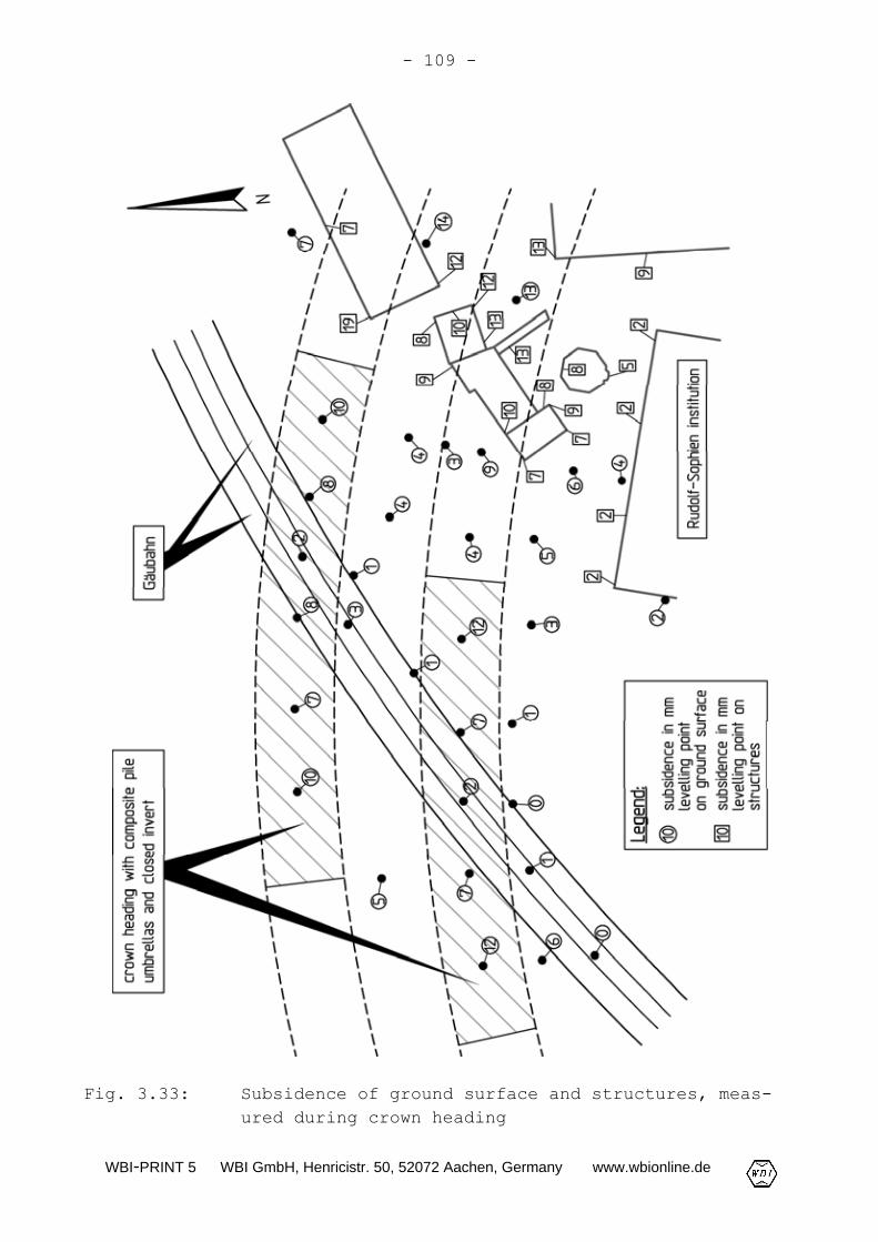
Fig. 3.33: Subsidence of ground surface and structures, meas-ured during crown heading

WBI-PRINT 5 WBI GmbH, Henricistr. 50, 52072 Aachen, Germany www.wbionline.de
- 110 -
In both tunnel tubes the crown heading was far ahead of the benchand invert excavation. Fig. 3.33 shows exemplarily the ground sur-face subsidence due to the crown heading in the area of the under-crossing of the Gäubahn and the buildings adjacent to the Rudolf-Sophien institution. In the area of the undercrossing of thebuildings adjacent to the Rudolf-Sophien institution the crownheading was carried out with an open invert and small roundlengths of 0.8 to 1.2 m following excavation class 4A-1 (see Fig.3.26). The subsidence measured here ranges from 7 to 19 mm. In thearea of the undercrossing of the Gäubahn the heading was changedover to a crown heading with closed invert under the protection ofan advancing support using composite piles and spiles (see Fig.3.27). The subsidence could thus be limited to 2 to 8 mm. Thissmall subsidence did at no point affect the railway traffic.
The measured ground surface subsidences are in good agreement withthe ones determined in the stability analyses. In the area of theundercrossing of the buildings adjacent to the Rudolf-Sophien in-stitution (analysis cross-section AC 2) a maximum surface subsi-dence of 11 mm was computed (see Fig. 3.31). The maximum surfacesubsidence computed for the undercrossing of the Gäubahn (analysiscross-section AC 3, see Fig. 3.23) amounts to 7 mm.
3.2.7 Conclusions
With a crown heading with open invert and small round lengths (ex-cavation class 4A-1, see Fig. 3.26) it was possible to achievesmall surface subsidence < 2 cm during tunneling in the alternat-ing sequence of sandstone and siltstone horizons of the Stuben-sandstone formation in the region of Stuttgart.
In order to avoid affecting the railway traffic during the under-crossing of the Gäubahn it was necessary in this area to limit thesubsidence to even smaller values. This was achieved mainly bysupporting the curved temporary crown invert with shotcrete. Forsafety reasons an additional advancing support with compositepiles was carried out. With a very small surface subsidence rang-ing from 2 to 8 mm it was possible to maintain the railway trafficwithout any interference.
In areas where the rock mass could not be excavated by a tunnelexcavator smooth blasting was carried out. It was possible toprove by measurements that the vibration velocities fell well be-

WBI-PRINT 5 WBI GmbH, Henricistr. 50, 52072 Aachen, Germany www.wbionline.de
- 111 -
low the reference values for the allowable structural vibrationsgiven in DIN 4150, Part 3 (DIN 4150-3, 1999).
The results of the geotechnical monitoring during construction arein good agreement with the surface subsidence computed in the sta-bility analyses. It could thus be shown that FE-analyses are agood basis for estimating the subsidence due to tunneling, if theparameters are assessed appropriate and the excavation and the in-stallation of the support are simulated realistically.
3.3 Hellenberg Tunnel, Germany
3.3.1 Introduction
The alignment of the new railway line Cologne-Rhine/Main runsthrough the Rhine schist mountains (Rheinisches Schiefergebirge)in NW-SE direction tightly bundled with the freeway (Autobahn) A3.Coming from Cologne, it crosses in particular the Siebengebirge,Westerwald and Taunus mountains. The alignment comprises more than30 tunnels with a total length of approx. 47 km. The HellenbergTunnel is one of six tunnels driven in the Taunus mountains andlies to the south of Idstein.
3.3.2 Structure
The new railway line Cologne-Rhine/Main of German Rail (DeutscheBahn AG) undercrosses the Hellenberg mountain in a 552 m long tun-nel. The maximum overburden of the tunnel amounts to approx. 19 m.
The tunnel sections in the portal areas were constructed by thecut-and-cover method. The central tunnel segment with a length ofapprox. 470 m was driven by underground construction ascendingfrom southeast to northwest (Fig. 3.34).
A mouth-shaped profile with an excavated width of 15.4 m and aheight of 12.3 m was constructed for the double-tracked HellenbergTunnel (Fig. 3.35). This is the standard profile for double-Tracked tunnels of the new railway line Cologne-Rhine/Main. Theexcavated cross-section amounts to approx. 150 m2 (Fig. 3.35).

WBI-PRINT 5 WBI GmbH, Henricistr. 50, 52072 Aachen, Germany www.wbionline.de
- 112 -
Fig. 3.34: Hellenberg Tunnel, site plan

WBI-PRINT 5 WBI GmbH, Henricistr. 50, 52072 Aachen, Germany www.wbionline.de
- 113 -
Fig. 3.35: New railway line Cologne-Rhine/Main, standard pro-file
In the vault area the radius of curvature of the shotcrete mem-brane amounts to R = 7.32 m. The invert is rounded with a radiusof R = 16.5 m. For the transition area from the sidewalls to the

WBI-PRINT 5 WBI GmbH, Henricistr. 50, 52072 Aachen, Germany www.wbionline.de
- 114 -
invert radii of R = 4.38 m and R = 2.5 m, respectively, were se-lected (Fig. 3.35).
Fig. 3.36 shows the southern portal at the start of undergroundexcavation of the Hellenberg Tunnel.
Fig. 3.36: Hellenberg Tunnel, southern portal
3.3.3 Ground and groundwater conditions
The ground along the alignment of the Hellenberg Tunnel was ex-plored by test pits and core drillings. The boreholes wereequipped as observation wells (Fig. 3.34 and 3.37).
The Quaternary talus material, which is loamified in the upper re-gion, extends to a depth of approx. 2 m. In the portal areas it isencountered down to a maximum depth of 5 m.
Below the Quaternary cover Devonian rocks follow composed in thearea of the Hellenberg Tunnel of phyllitic slate with sandstoneand quartzite intercalations and embedded conglomerate lenses.These layers are referred to as Variegated Schist.
WBI-PRINT 5 WBI GmbH, Henricistr. 50, 52072 Aachen, Germany www.wbionline.de
- 115 -
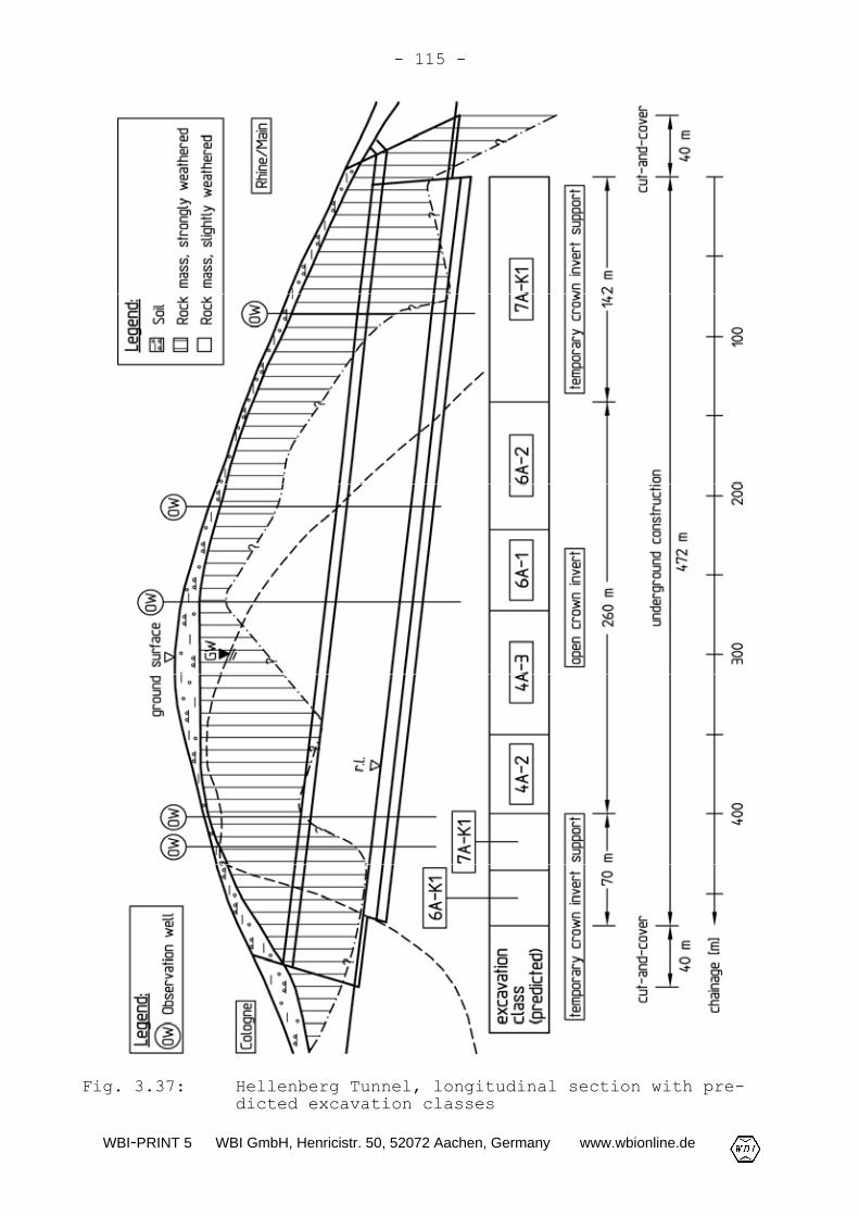
Fig. 3.37: Hellenberg Tunnel, longitudinal section with pre-dicted excavation classes

WBI-PRINT 5 WBI GmbH, Henricistr. 50, 52072 Aachen, Germany www.wbionline.de
- 116 -
The rock mass in the area of the Hellenberg Tunnel is character-ized by a deep-reaching weathering extending to a depth of some35 m. Unweathered rock mass is thus only encountered below thetunnel's invert.
In the course of the exploration the drill cores and the test pitswere geotechnically mapped. Further, television probing and labo-ratory and in-situ tests were carried out.
From the northern tunnel portal the groundwater table rises to12 m above the tunnel roof. In the following, it drops towards thesouthern tunnel portal to below the tunnel's invert. The groundwa-ter table mapped in the tunnel's longitudinal section (Fig. 3.37)is based on the highest groundwater levels measured in the bore-holes equipped as observation wells.
3.3.4 Excavation classes
Because of the size of the excavation profile it was necessary tosubdivide excavation and support into crown, bench and invert(Fig. 3.35). An advancing crown excavation was carried out.
A prediction of the distribution of the excavation classes basedon the results of the exploration and of stability analyses and onexperience is shown in Fig. 3.37. According to the drilling re-sults, the strongly weathered rock extends in the portal areas toabout the tunnel's invert. Accordingly, excavation classed with atemporary crown invert support were planned here (6A-K1 and 7A-K1,see DGGT, 1995: Table 1). In the central tunnel section it was ex-pected that the crown heading can be carried out with an open in-vert. In parts excavation classes without advance support measures(4A-2 and 4A-3, see DGGT, 1995: Table 1) were predicted. For othersections it was assumed that the heading requires advance support(excavation classes 6A-1 and 6A-2, see DGGT, 1995: Table 1).
The excavation methods, round lengths and support measures plannedfor excavation classes 6A-1 and 6A-2 are shown in Fig. 3.38 and3.39.
It was planned to carry out the excavation mainly by tunnel exca-vators and hydraulic chisels. In areas in which the tunnel was lo-cated in slightly weathered and slightly jointed rock, local loos-ening blasting was planned.

WBI-PRINT 5 WBI GmbH, Henricistr. 50, 52072 Aachen, Germany www.wbionline.de
- 117 -
Fig. 3.38: Excavation classes 6A-1 and 6A-2
The unsupported round lengths during the crown excavation werespecified in excavation class 6A-1 as 0.80 to 1.20 m and in exca-vation class 6A-2 as 1.21 to 1.60 m (Fig. 3.38 and 3.39). In bothexcavation classes an advance support of the crown with 3 to 4 mlong mortar spiles was provided for (Fig. 3.38 and 3.39). Shot-crete of grade B25 was selected for the shotcrete membrane at athickness of 25 cm and reinforced inside and outside by steel fab-ric mats Q221 (Fig. 3.38 and 3.39). In the sidewall area a system-atic anchoring with at least twelve 4 m long SN-anchors per tunnelmeter was planned (Fig. 3.38 and 3.39).

WBI-PRINT 5 WBI GmbH, Henricistr. 50, 52072 Aachen, Germany www.wbionline.de
- 118 -
Fig. 3.39: Support for excavation classes 6A-1 and 6A-2:a) Cross-section; b) longitudinal section
WBI-PRINT 5 WBI GmbH, Henricistr. 50, 52072 Aachen, Germany www.wbionline.de
- 119 -
A possible installation of anchors in the roof area ought to bedecided on site. For each round one steel set (lattice girder) wasto be installed in the crown area (Fig. 3.38 and 3.39).
The trailing distance of the bench (section D in Fig. 3.38) andthe closing of the invert (section E in Fig. 3.38) was to bespecified depending on the results of monitoring during heading,the encountered geotechnical conditions and the results of thestability analyses.
The unsupported round lengths were specified in excavation class6A-1 for the bench and the invert as 1.60 to 2.40 m and ≤ 3.60 m,respectively. In excavation class 6A-2 the corresponding roundlengths amounted to 2.41 to 3.20 m and ≤ 4.80 m, respectively(Fig. 3.38).
To improve the stability, the shotcrete membrane was to be widenedto t = 60 cm in the area of the crown and bench support feet ifnecessary. It is shown calculational in Wittke et al. (1986), Wit-tke (1990) and Wittke (1998), however, that the stability of acrown heading with open invert can only slightly be improved bythese kind of measures.
3.3.5 Crown heading
The excavation classes were finally specified during the crownheading on the basis of the results of stability analyses, ofcrown face mappings (see Chapter 3.3.6) and of the monitoring re-sults.
The crown was excavated over the entire tunnel length without atrailing bench excavation (unlimited length of section D in Fig.3.38). In the area of the southern portal a crown heading with atemporary support of the invert was carried out over a length ofapprox. 80 m (excavation class 7A-K1, Fig. 3.40). At the northernportal a temporary support of the invert was only constructed inthe beginning of excavation (excavation class 6A-K1, Fig. 3.40).
In the remaining area a crown heading with open invert was carriedout (excavation classes 6A-1 and 6A-2, Fig. 3.40).

WBI-PRINT 5 WBI GmbH, Henricistr. 50, 52072 Aachen, Germany www.wbionline.de
- 120 -
Fig. 3.40: Hellenberg Tunnel, longitudinal section and excava-tion classes, as carried out

WBI-PRINT 5 WBI GmbH, Henricistr. 50, 52072 Aachen, Germany www.wbionline.de
- 121 -
3.3.6 Results of the crown face mapping
The evaluation of the crown face mapping resulted in a modifiedelevation of the boundary between strongly and slightly weatheredrock as compared to the exploration results (Fig. 3.37 and 3.40).Nevertheless, the predicted distribution of excavation classesagreed well with the construction (Fig. 3.37 and 3.40).
During the tunnel face mapping the appearance, the extent and theorientation of the discontinuities were determined as well.
Fig. 3.41 shows as an example the crown face mapping at chainage345.4 m. The strike and dip angles of the discontinuities weremeasured using a geological compass (see Chapter 2.5.1). For rea-sons of clarity of the representation only some of the measureddiscontinuity orientations are mapped in Fig. 3.41.
Fig. 3.41: Crown face mapping, chainage 345.4 m

WBI-PRINT 5 WBI GmbH, Henricistr. 50, 52072 Aachen, Germany www.wbionline.de
- 122 -
In Fig. 3.42 all discontinuity orientations measured from chainage300 to 350 m are shown in a polar diagram (see Chapter 2.5.1). Ac-cordingly the discontinuities can mainly be assigned to threesets.
Fig. 3.42: Measured discontinuity orientations, chainage 300 to350 m, polar diagram
The bedding planes and foliation discontinuities display the NE-SWstrike typical for the Rhine schist mountains and dip at a moder-ate steep to steep angle (50 to 80°) towards northwestern direc-tions. Two joint sets J1 and J2 further exist dipping mostlysteeply (60 to 90°) and striking parallel to the tunnel axis (Fig.3.42).
Fig. 3.43 shows the bench at the southern portal. The photographgives an impression of the strongly weathered rock in this areaand of the discontinuity fabric.

WBI-PRINT 5 WBI GmbH, Henricistr. 50, 52072 Aachen, Germany www.wbionline.de
- 123 -
Fig. 3.43: Bench at the southern portal
3.3.7 Stability analyses for the bench excavation
Within the tunnel sections driven according to excavation classes6A-1 and 6A-2 an advancing crown excavation with open invert andtrailing bench and invert excavation was planned (Fig. 3.38). Theevaluation of the mapping carried out during the crown heading re-vealed, however, that the steep joints J1 and J2 striking parallelto acute-angled to the tunnel axis (see Fig. 3.42) appear fre-quently in some areas and have a large extent. Before the start ofthe bench excavation the stability of the tunnel in this construc-tion stage was therefore investigated in FE-analyses with the pro-gram system FEST03 (Wittke, 2000). On the basis of the results ofthese analyses the length of the section E between bench and in-vert excavation (see Fig. 3.38) was to be specified.
Fig. 3.44 shows the computation section, the FE-mesh, the groundprofile and the parameters taken as a basis for the stabilityanalyses (Wittke et al., 1999). The tunnel cross-section is lo-cated in the strongly to slightly weathered Variegated Schist. Theoverburden is 18 m high. Below the tunnel's invert the rock is un-weathered.

WBI-PRINT 5 WBI GmbH, Henricistr. 50, 52072 Aachen, Germany www.wbionline.de
- 124 -
Fig. 3.44: Computation section, FE-mesh, ground profile and pa-rameters
As mentioned above, the foliation or bedding, respectively,strikes approx. perpendicularly to the tunnel axis and dipssteeply (see Fig. 3.42). Since discontinuities of this orientationhardly influence the load transfer in transverse tunnel direction,the foliation/bedding was not taken into account in the analyses.The shear strength of the joints J1 and J2, which are relevant forthe stability, was, however, accounted for. The shear strength wasfurthermore varied because of the different appearance of thesediscontinuities. Three cases were investigated, in which the fric-tion angles on the joints ϕJ were assumed as 20°, 22.5° and 25° andthe cohesion as cJ = 0. The anchoring of the rock provided for inall excavation classes was not taken into account in the analysesas a conservative assumption.
The heading of the tunnel was simulated in four computation steps(Fig. 3.45). In the 1st computation step the in-situ state ofstress and deformation resulting from the dead weight of the rockmass was computed. After that, the excavation of the crown (2nd

WBI-PRINT 5 WBI GmbH, Henricistr. 50, 52072 Aachen, Germany www.wbionline.de
- 125 -
computation step) and the bench (3rd computation step) was simu-lated, each time with simultaneous installation of the shotcretemembrane. In the 4th computation step the invert was excavated andsupported using shotcrete.
Fig. 3.45: Computation steps

WBI-PRINT 5 WBI GmbH, Henricistr. 50, 52072 Aachen, Germany www.wbionline.de
- 126 -
A thickness of t = 25 cm (see Fig. 3.35) and a Young's modulus ofE = 15,000 MN/m2 were specified for the shotcrete membrane.
Fig. 3.46 shows the development of the displacements computed forthe bench support feet in the course of the viscoplastic iterativeanalysis in the 3rd computation step.
Fig. 3.46: Viscoplastic displacements depending on the shearstrength of the joint sets J1 and J2, 3rd computa-tion step
For the case ϕJ = 25° the stability of the construction stage dueto the bench excavation can be proven in the analysis. The hori-zontal and vertical displacements computed at the bench supportfeet converge in the course of the viscoplastic iterative analysis(see Fig. 3.46). The horizontal and vertical components of theviscoplastic displacements of the bench support feet amount to
vpHδ = 15.6 mm and vp
Vδ = 9.2 mm.
With decreasing friction angle ϕJ markedly larger viscoplastic dis-placements are computed (see Fig. 3.46). In the case ϕJ = 20° thedisplacements do not converge in the analysis (see Fig. 3.46). The

WBI-PRINT 5 WBI GmbH, Henricistr. 50, 52072 Aachen, Germany www.wbionline.de
- 127 -
stability of the construction stage as a result of the bench exca-vation can thus not be proven by the analysis for this case.
Summarizing it may be stated that the stability of the tunnel dur-ing bench excavation depends to a large degree on the friction an-gle ϕJ on the joints.
On the basis of the results of the stability analyses it wasagreed upon for those sections in which the crown was excavatedwithout invert support to set no limit for the length of the sec-tion E between bench excavation and the support of the invert (seeFig. 3.38). With the bench mapping during heading, however, greatimportance was attached to recording the appearance and extent ofthe joints. Whenever strongly jointed rock was encountered duringbench excavation, the anchoring of the sidewalls was intensified.
3.3.8 Construction and monitoring results
Fig. 3.47 shows the sequence of the heading. Following the crownheading (1), the bench was excavated up to chainage approx. 80 mat a round length of 2.0 m. The invert trailed with a round lengthof 3.6 m and was supported after each round (2). In this area thestrongly weathered rock mass extends into the tunnel cross-section(Fig. 3.47), and a crown invert support was installed.
After that, the bench was excavated from chainage 80 m to 462 mwith a round length of 2.4 m (3 in Fig. 3.47). As mentioned, theanchoring was locally intensified because of the heavy jointing ofthe rock mass.
In the northern portal area the bench was excavated again with im-mediately trailing invert over a short tunnel section (4 in Fig.3.47). The round lengths were the same as in the southern portalarea.
Finally, the invert was excavated backward and supported withround lengths of 3.6 m (5 in Fig. 3.47).
The heading was accompanied by a geotechnical monitoring programincluding surface leveling, extensometer and inclinometer measure-ments from the ground surface and leveling and convergency meas-urements in the tunnel.

WBI-PRINT 5 WBI GmbH, Henricistr. 50, 52072 Aachen, Germany www.wbionline.de
- 128 -
Fig. 3.47: Excavation, heading sequence

WBI-PRINT 5 WBI GmbH, Henricistr. 50, 52072 Aachen, Germany www.wbionline.de
- 129 -
Fig. 3.48: Measured vertical displacements at the bench supportfeet

WBI-PRINT 5 WBI GmbH, Henricistr. 50, 52072 Aachen, Germany www.wbionline.de
- 130 -
Fig. 3.48 shows exemplarily the maximum subsidence at the benchsupport feet measured after bench excavation. Since the elasticpart of the displacements had mostly occurred already before thezero reading, it could not be recorded by the measurements. Themeasurement results were therefore compared to the computed visco-plastic displacement parts shown in Fig. 3.46. It becomes apparentthat the measured displacements are smaller than the viscoplasticvertical displacements computed assuming a friction angle ofϕJ = 25° (approx. 10 mm). It thus turns out that the constructionstage following the bench excavation was stable as predicted.
3.3.9 Conclusions
Crown headings are carried out in excavation classes with andwithout invert support, depending on the rock conditions. Sincethe different excavation classes vary strongly in cost, great im-portance is attached to the appropriate specification. The exampleof the Hellenberg Tunnel shows how the excavation classes can bespecified safely on the basis of the results of stability analy-ses, mapping during construction and monitoring. It becomes appar-ent that proofs of stability according to the FE-method can con-tribute essentially towards the prediction of and decision on theexcavation classes.
Related Documents