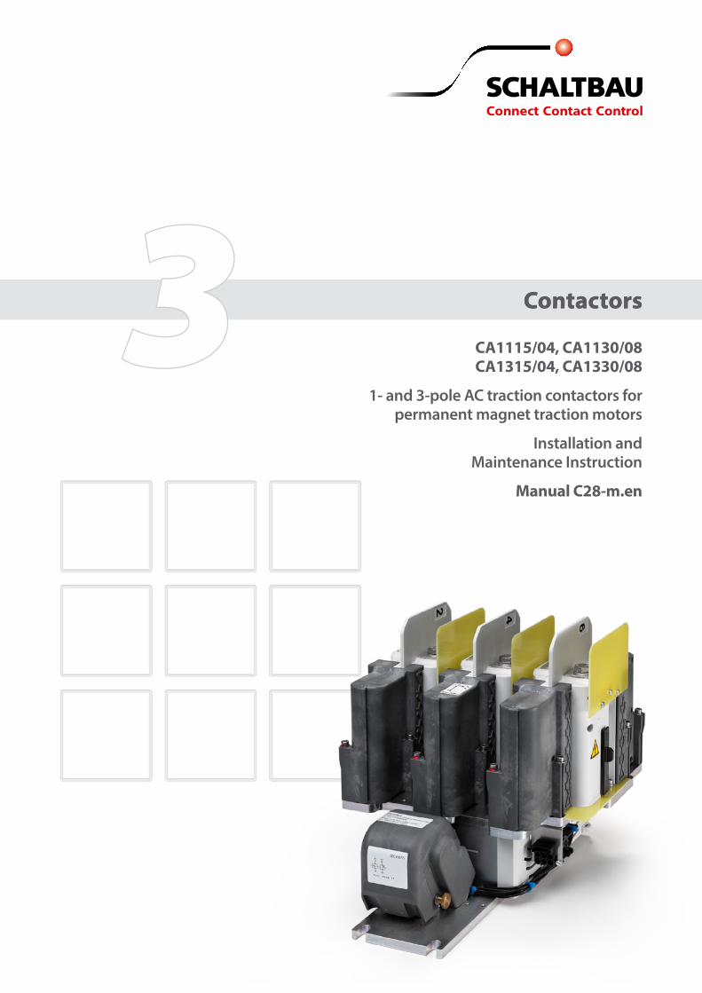
3 3 Contactors CA1115/04, CA1130/08 CA1315/04, CA1330/08 1- and 3-pole AC traction contactors for permanent magnet traction motors Installation and Maintenance Instruction Manual C28-m.en Contactors

Welcome message from author
This document is posted to help you gain knowledge. Please leave a comment to let me know what you think about it! Share it to your friends and learn new things together.
Transcript
33 Contactors
CA1115/04, CA1130/08 CA1315/04, CA1330/08
1- and 3-pole AC traction contactors for permanent magnet traction motors
Installation and Maintenance Instruction
Manual C28-m.en
Contactors
2 2021-03-09 / V1.0
Contactors CA Series – Installation and Maintenance Instructions
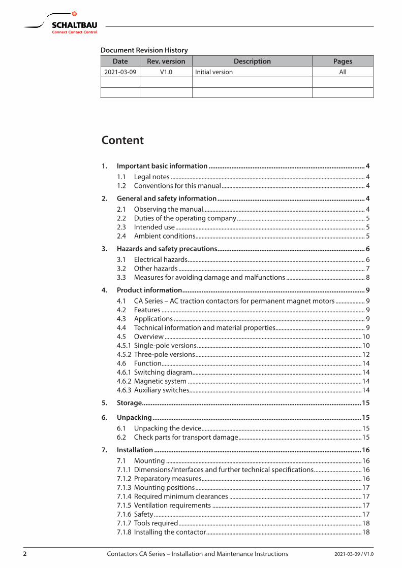
Document Revision HistoryDate Rev. version Description Pages
2021-03-09 V1.0 Initial version All
Content
1. Important basic information ......................................................................................... 41.1 Legal notes .............................................................................................................................. 41.2 Conventions for this manual ............................................................................................. 4
2. General and safety information .................................................................................... 42.1 Observing the manual......................................................................................................... 42.2 Duties of the operating company ................................................................................... 52.3 Intended use ........................................................................................................................... 52.4 Ambient conditions.............................................................................................................. 5
3. Hazards and safety precautions .................................................................................... 63.1 Electrical hazards ................................................................................................................... 63.2 Other hazards ......................................................................................................................... 73.3 Measures for avoiding damage and malfunctions ................................................... 8
4. Product information ........................................................................................................ 94.1 CA Series – AC traction contactors for permanent magnet motors ................... 94.2 Features .................................................................................................................................... 94.3 Applications ............................................................................................................................ 94.4 Technical information and material properties .......................................................... 94.5 Overview ................................................................................................................................104.5.1 Single-pole versions ...........................................................................................................104.5.2 Three-pole versions ............................................................................................................124.6 Function ..................................................................................................................................144.6.1 Switching diagram ..............................................................................................................144.6.2 Magnetic system .................................................................................................................144.6.3 Auxiliary switches................................................................................................................14
5. Storage.............................................................................................................................15
6. Unpacking .......................................................................................................................156.1 Unpacking the device ........................................................................................................156.2 Check parts for transport damage ................................................................................15
7. Installation ......................................................................................................................167.1 Mounting ...............................................................................................................................167.1.1 Dimensions/interfaces and further technical specifications ...............................167.1.2 Preparatory measures ........................................................................................................167.1.3 Mounting positions ............................................................................................................177.1.4 Required minimum clearances ......................................................................................177.1.5 Ventilation requirements .................................................................................................177.1.6 Safety .......................................................................................................................................177.1.7 Tools required .......................................................................................................................187.1.8 Installing the contactor .....................................................................................................18
32021-03-09 / V1.0 Contactors CA Series – Installation and Maintenance Instructions
7.2 Electrical connection .........................................................................................................197.2.1 Electrical data and other technical specifications ...................................................197.2.2 Preparatory measures ........................................................................................................197.2.3 Safety .......................................................................................................................................207.2.4 Tools required .......................................................................................................................207.2.5 Connecting the auxiliary switches ................................................................................217.2.6 Connecting the coil terminals ........................................................................................237.2.7 Bundle and fix the control wires ....................................................................................247.2.8 Connecting the main contacts .......................................................................................24
Connecting the main contacts using cables .............................................................24Connecting the main contacts using busbars ..........................................................25
7.3 Connecting the earth terminal ......................................................................................267.4 Checks .....................................................................................................................................27
8. Maintenance ...................................................................................................................288.1 Safety .......................................................................................................................................288.2 Preventive maintenance ...................................................................................................288.2.1 Intervals for regular tests/checks ..................................................................................288.2.2 Regular tests/checks ..........................................................................................................298.3 Corrective maintenance ...................................................................................................328.3.1 Replacing the arcing chambers .....................................................................................32
Spare parts required ..........................................................................................................32Tools required .......................................................................................................................32Preconditions ........................................................................................................................32Disassemble the arcing chambers ................................................................................32Installing the arcing chambers .......................................................................................33
8.3.2 Checking the main contacts ...........................................................................................33Tools required .......................................................................................................................33Preconditions ........................................................................................................................33Checking the main contacts for wear ..........................................................................33
8.3.3 Replacing the main contacts ..........................................................................................34Spare parts required ..........................................................................................................34Tools/Auxiliaries required .................................................................................................34Preconditions ........................................................................................................................34Disassemble the switching unit .....................................................................................34Disassemble the contact bridge ....................................................................................36Installing the contact bridge ...........................................................................................37Installing the switching unit ...........................................................................................39Check the contact bridge carrier ...................................................................................40Final installation steps .......................................................................................................40
8.3.4 Replacing the auxiliary switches ...................................................................................41Spare parts required ..........................................................................................................41Tools required .......................................................................................................................41Preconditions ........................................................................................................................41Disassemble the auxiliary switch assembly ...............................................................41Replace the auxiliary switch sub-assembly S870 or S970 ....................................42Replace the S826 auxiliary switches .............................................................................42Adjust the auxiliary switch assembly ...........................................................................42Install the auxiliary switch assembly ............................................................................43
8.4 Checks .....................................................................................................................................44
9. Spare parts ......................................................................................................................45
10. Technical data .................................................................................................................46
11. Disposal ...........................................................................................................................46
4 2021-03-09 / V1.0
Important basic information
Contactors CA Series – Installation and Maintenance Instructions
1. Important basic information
1.1 Legal notesWithout prior written consent of SCHALTBAU GmbH, this manual is not allowed to be electronically or me-chanically reproduced – as a whole or in parts – be dis-tributed, changed, transmitted, translated into another language or used in any other way.SCHALTBAU GmbH cannot be held liable for damage caused by non- or only partial observation of the manual.
1.2 Conventions for this manualThis manual describes the installation and maintenance of the contactors.Cross references are presented in bold italics.To highlight particularly important safety instructions and other information, the following symbols are used in this manual:
DANGERIndicates a directly threatening dangerous situation. Death or severe injuries will result if it is not prevented.
WARNINGIndicates a possibly dangerous situation. Death or severe injuries may result if it is not prevented.
CAUTIONIndicates a possibly dangerous situation. Medium or minor injuries may result if it is not prevented.
ATTENTIONIndicates a possibly detrimental situation. If it is not prevented, assemblies, the system or property in its surroundings could be damaged.
Indicates technical features and methods to simplify working or indicates informa-tion of particular importance.
This manual refers to 1-pole and 3-pole contactors of the CA series: - 1-pole: CA 1115/04, CA 1130/08 - 3-pole: CA 1315/04, CA 1330/08
This manual describes only stock items of the above mentioned contactor types. If you need a special vari-ant feel free to contact us.
2. General and safety informationThe contactors dealt with in this document are intend-ed for use with electrical systems for special applica-tions. They are designed and tested in compliance with generally accepted codes of practice. However, improp-er use, operation, handling, maintenance of or tamper-ing with electric equipment can cause serious or fatal injury to the user or others, and the appliance or other property can be damaged. Consequently, the opera-tion, maintenance and installation instructions for the contactors must be strictly followed.If anything is not clear, clarification must be sought with any queries stating the device type and the serial number. Only authorised and trained personnel are allowed to plan and carry out all mechanical and electrical instal-lations, transport, commissioning, as well as mainte-nance and repair work.This applies to the observation of the general installa-tion and safety regulations for electrical systems as well as the proper use of tools approved for this purpose. Electrical equipment requires protection from moisture and dust during installation, operation and storage.
2.1 Observing the manual
X All personnel must read and understand the in-structions in this manual and adhere to them when working with the device.
X Always adhere strictly to all safety instructions!
52021-03-09 / V1.0 Contactors CA Series – Installation and Maintenance Instructions
General and safety information
2.2 Duties of the operating company X Observe all applicable national regulations, all safety,
accident prevention and environmental protection regulations as well as the recognised technical rules for safe and correct working.
X Regularly check all fitted protection and safety equip-ment for correct function.
X Work on electrical equipment must only be carried out by a qualified electrician or by instructed persons under the supervision and control of a qualified elec-trician in accordance with electrical regulations.
X A specialist is someone who, on the basis of his technical training, knowledge and experience as well as knowledge of the relevant regulations, is able to assess the work assigned to him and recog-nize possible hazards.
X Work on the contactors must only be carried out by personnel who meet the requirements set out in this manual.
X Personnel must be clearly informed about who is responsible for the maintenance of the contactors.
X Always perform complete checks after any instal-lation work and/or after any other conversions, al-terations or maintenance, in accordance with the following standards: - EN/IEC 60077-2 - EN/IEC 60947-4-1
2.3 Intended use
X The contactors have been designed and tested ac-cording to national and international standards. Due to their unique features they can also be used in a wide range of industrial applications.
X The contactors must only be used under operat-ing conditions according to the technical specifi-cations and the instructions in this manual.
X None of the conditions of use, such as voltages, currents or ambient conditions, defined in the corresponding technical data sheets or in our C28 catalogue may be overridden. The catalogue is available under: https://www.schaltbau.com/en/media-library/
X The contactors may only be used when all protec-tive devices are present, have been correctly in-stalled and are fully operational.
X Contactors may not be used without other safety precautions in potentially explosive atmospheres and/or in aggressive media.
X To ensure the requirements of basic insulation, the base plate of the contactor must be earthed in a shock and vibration resistant way.
X Coil suppression for reducing surges when the coil is switched off is optimally attuned to the contac-tor‘s switching behaviour. The existing opening characteristic must not be negatively influenced by parallel connection with an external diode.
X Operation without a properly mounted arc cham-ber is not permitted.
X Do not use the contactor without protective cov-ers (for coil terminals and auxiliary switches).
X The contactor has unprotected live parts and car-ries labels that warn of the hazard. This warnings must be observed and the labels must not be re-moved in any way.
X The prescribed clearances to other live parts or earth and other parts must be observed as well as the safety regulations of the applicable standards.
X Switching at close to the maximum breaking ca-pacity may require increased minimum clearanc-es! Do not hesitate to ask our advice in respect of any dimensioning.
X Improper handling of the contactors, e.g. impacts on the floor, may result in breakage, cracks or de-formation. Always handle the device with care.
X Only use the contactors for the specified applica-tion and only with original parts. Any other usage of or tampering with the contactors is considered contrary to their intended use. No liability is as-sumed for damages and accidents caused due to non-compliance with the instructions in this man-ual or improper use of the contactors.
2.4 Ambient conditions
ATTENTIONThe contactors have been designed for specific am-bient conditions.
X Only operate the contactors in ambient condi-tions, such as temperature ranges, degree of soiling, etc., as defined in the corresponding data sheets and in our C28 catalogue. The cata-logue is available under: https://www.schaltbau.com/en/media-library/
6 2021-03-09 / V1.0
Hazards and safety precautions
Contactors CA Series – Installation and Maintenance Instructions
3. Hazards and safety precautions
3.1 Electrical hazards
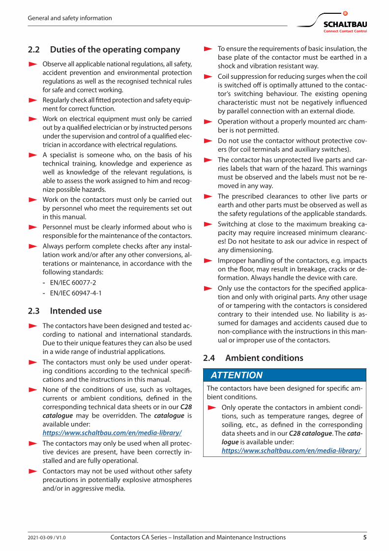
DANGERThe contactors are used for high voltage switching. Contact with live electrical parts can result in serious injuries or even death! Live parts are all metal parts belonging directly to one of the circuits or wires connecting to them. All other visible metal parts and wiring may also be live if a fault exists.Before starting any work on the contactors, always comply with the following safety rules:
X Disconnect on all sides X Secure to prevent switching back on X Clearly identify the working area X Check that a voltage-free state exists X Earth and short circuit; this includes discharging any capacitors in the main circuit X Besides the main power circuits, also disconnect additional and auxiliary circuits X Cover or insulate adjacent live parts X The presence of a voltage-free state can only be clearly identified by a qualified electrician. X When the work has been concluded, follow the procedure in reverse.
DANGERThe contactors are equipped with two protective caps for the coil terminal and auxiliary switches.The protective caps are parts of the insulation system. Operation of the contactors without the pro-tective caps may result in serious injuries or even death!
X Never operate the contactors without the two protective caps. X When removing the protective caps during installation or maintenance works, make sure that
the protective caps are re-installed before the contactors are put into service.
DANGERThe contactors are equipped with a protective earth terminal. Without earth connection, metal parts and wires may be energized in the case of a failure. Risk of serious injuries or even death!
X Make sure that the contactors are connected to earth. X Make sure that the wire gauge of the earthing cables complies with the specific short circuit
conditions.
DANGERIn the case of a failure of the equipment;
X don‘t use it anymore X immediately contact the manufacturer..
72021-03-09 / V1.0 Contactors CA Series – Installation and Maintenance Instructions
Hazards and safety precautions
DANGERInterventions in the equipment may cause serious impairments to the safety of men and construc-tions. They are not permissible and lead to an exclusion of liability and warranty.
DANGERAll checks and the replacement of components or groups of components may only be carried out by qualified personnel according to the instructions of Schaltbau. All spare parts must be parts de-livered by or released by Schaltbau.
3.2 Other hazards
WARNINGContactors must only be used for the purposes specified in the specifications and data sheets. Incor-rect use can cause accidents and severe personal injury.
X The manufacturer will not be responsible for accidents arising from improper use of the product.
WARNINGThe contactor is heavy. Risk of injury and damage to the device.
X Take care when handling the contactor. X Two or more persons are required to unpack, transport and install the contactor. X When carrying the contactor always hold it on the base plate.
CAUTIONDuring continuous operation the contactors may become hot. Risk of burns!
X Before beginning any checks or maintenance on the contactors ensure that the heated com-ponents have cooled down.
CAUTIONThe contactors contain sharp-edged parts. Risk of injuries!
X Use appropriate tools for installation and maintenance work on the contactors. X Wear safety gloves when handling sharp-edged components.
8 2021-03-09 / V1.0
Hazards and safety precautions
Contactors CA Series – Installation and Maintenance Instructions
3.3 Measures for avoiding damage and malfunctions
ATTENTIONAggressive liquids may damage the contactors.
X Ensure the contactors do not come into contact with aggressive liquids.
ATTENTIONImproper handling of the contactors, e.g. dropping on the floor, can result in breaks, cracks and deformation.
X Ensure the contactors are always handled correctly. X Do not throw the contactors on the floor. X At regular intervals perform a visual check of the contactors for possible damage. X Immediately replace any damaged parts.
ATTENTIONDepending on the product type, contactors can contain permanent magnets. Such magnets can attract ferro-magnetic parts resulting in damage to the contactors.
X Ensure that the contactors are installed in a location where it is not possible for them to attract any ferro-magnetic parts.
ATTENTIONDepending on the product type, contactors can contain permanent magnets. These permanent magnets can destroy the data on the magnetic strips of credit or similar cards.
X Keep credit or similar cards away from the contactors.
ATTENTIONDuring switching off, strong electromagnetic fields are generated in the vicinity of the contactors. These may influence other components close to the contactors.
X Make sure that the contactors are installed in a location where no other components are affected.
ATTENTIONIn the case of damage, wear and/or soiling of the contactors - in the form of a partial break, sharp edges and discoloured surfaces - the functional reliability of the contactors is no longer ensured.
X Visually inspect the contactors regularly to detect wear and soiling. X Replace damaged parts immediately. X Immediately remove any soiling without leaving any residues. X Immediately replace any parts with persistent soiling.
ATTENTIONDetent-edged rings and detent-edged washers have a limited life time. After screws secured with detent-edged rings or detent-edged washers have been undone three times, the rings or washers must be replaced by new ones.
X Record the frequency of undoing of the screws in the work log. X Replace detent-edged rings or detent-edged washers with new ones after the screws have been undone
three times.
92021-03-09 / V1.0 Contactors CA Series – Installation and Maintenance Instructions
Product information
4. Product information
4.1 CA Series – AC traction contactors for permanent magnet motors
With the CA contactor series Schaltbau is introducing an innovative contactor concept to the market. It en-sures the reliable disconnection of the motors from the traction inverter of electric multiple units. Disconnect-ing the motors becomes necessary in the event of a short-circuit in the output circuit of the inverter in order to prevent the drive from being blocked.The outstanding feature of this new contactor series is the controlling of modern traction motors with fre-quencies up to 400 Hz!Due to its technical features, its compact design, its high switching functionality and reliability, the CA Se-ries contactor offers flexibility and versatility found in no other contactor. The product family comprises a number of various design versions catering to a wide range of uses.
4.2 Features
X Innovative design: compact, rugged, reliable X High short-circuit breaking capacity for frequen-
cies up to 400 Hz X Double-break contacts X 1-pole or 3-pole versions X Easy maintenance:
- Easy inspection and replacement of contacts - Easy replacement of arc chute
X Drive with coil tolerance according to railway standard
X Insulation coordination: - Functional insulation of main circuit - Basic insulation between main circuit and pro-
tective earth - Reinforced insulation between main circuit and
control circuit /auxiliary circuit
4.3 ApplicationsCA Series contactors are designed for load-free switch-ing of traction motors of electric multiple units. In the event of a system fault, e.g. a short circuit in the traction inverter, the traction motors are instantly and reliably switched off, irrespective of the operating situation of the motor.
4.4 Technical information and material properties
For technical information and material properties, refer to the corresponding data sheets and to our C28 cata-logue. The catalogue is available under: https://www.schaltbau.com/en/media-library/
10 2021-03-09 / V1.0
Product information
Contactors CA Series – Installation and Maintenance Instructions
4.5 Overview
4.5.1 Single-pole versions
I
D
E12 - 15 Nm
F
G
16 - 20 Nm
H
C
B
A
G
J
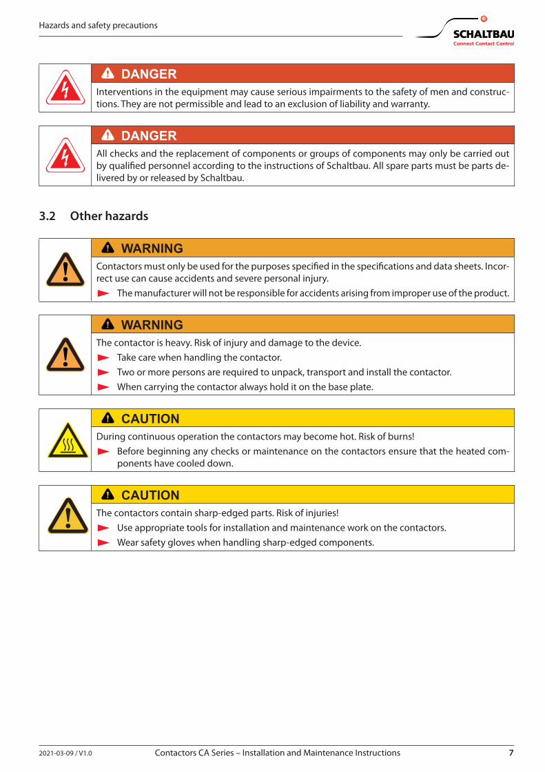
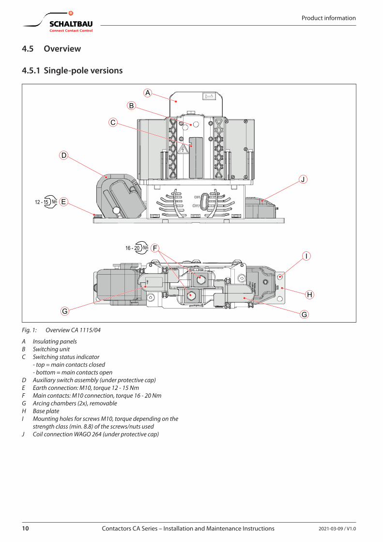
Fig. 1: Overview CA 1115/04
A Insulating panelsB Switching unitC Switching status indicator - top = main contacts closed - bottom = main contacts openD Auxiliary switch assembly (under protective cap)E Earth connection: M10, torque 12 - 15 NmF Main contacts: M10 connection, torque 16 - 20 NmG Arcing chambers (2x), removableH Base plateI Mounting holes for screws M10, torque depending on the
strength class (min. 8.8) of the screws/nuts usedJ Coil connection WAGO 264 (under protective cap)
112021-03-09 / V1.0 Contactors CA Series – Installation and Maintenance Instructions
Product information
I
J
H
D
E12 - 15 Nm
F
G
16 - 20 Nm
G
C
B
A
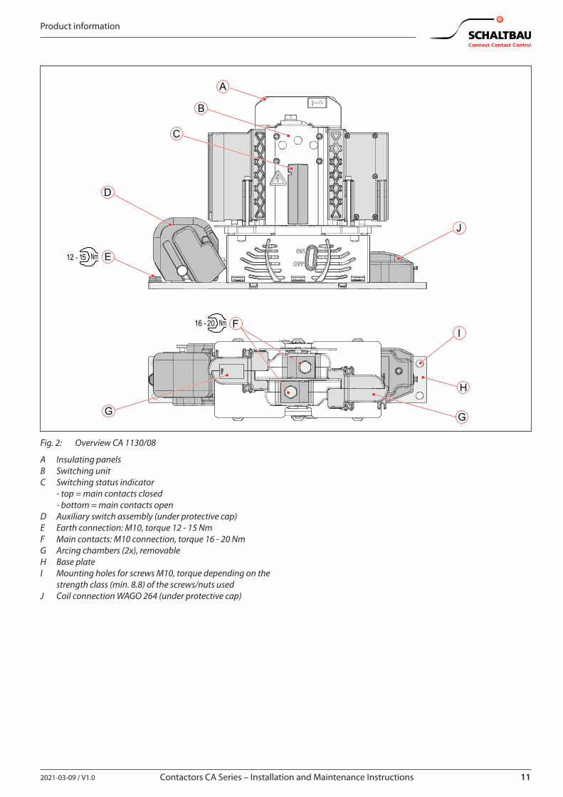
Fig. 2: Overview CA 1130/08
A Insulating panelsB Switching unitC Switching status indicator - top = main contacts closed - bottom = main contacts openD Auxiliary switch assembly (under protective cap)E Earth connection: M10, torque 12 - 15 NmF Main contacts: M10 connection, torque 16 - 20 NmG Arcing chambers (2x), removableH Base plateI Mounting holes for screws M10, torque depending on the
strength class (min. 8.8) of the screws/nuts usedJ Coil connection WAGO 264 (under protective cap)
12 2021-03-09 / V1.0
Product information
Contactors CA Series – Installation and Maintenance Instructions
4.5.2 Three-pole versions
I
H
D
E 12 - 15 Nm
F
G
I
16 - 20 Nm
G
K
C B
A
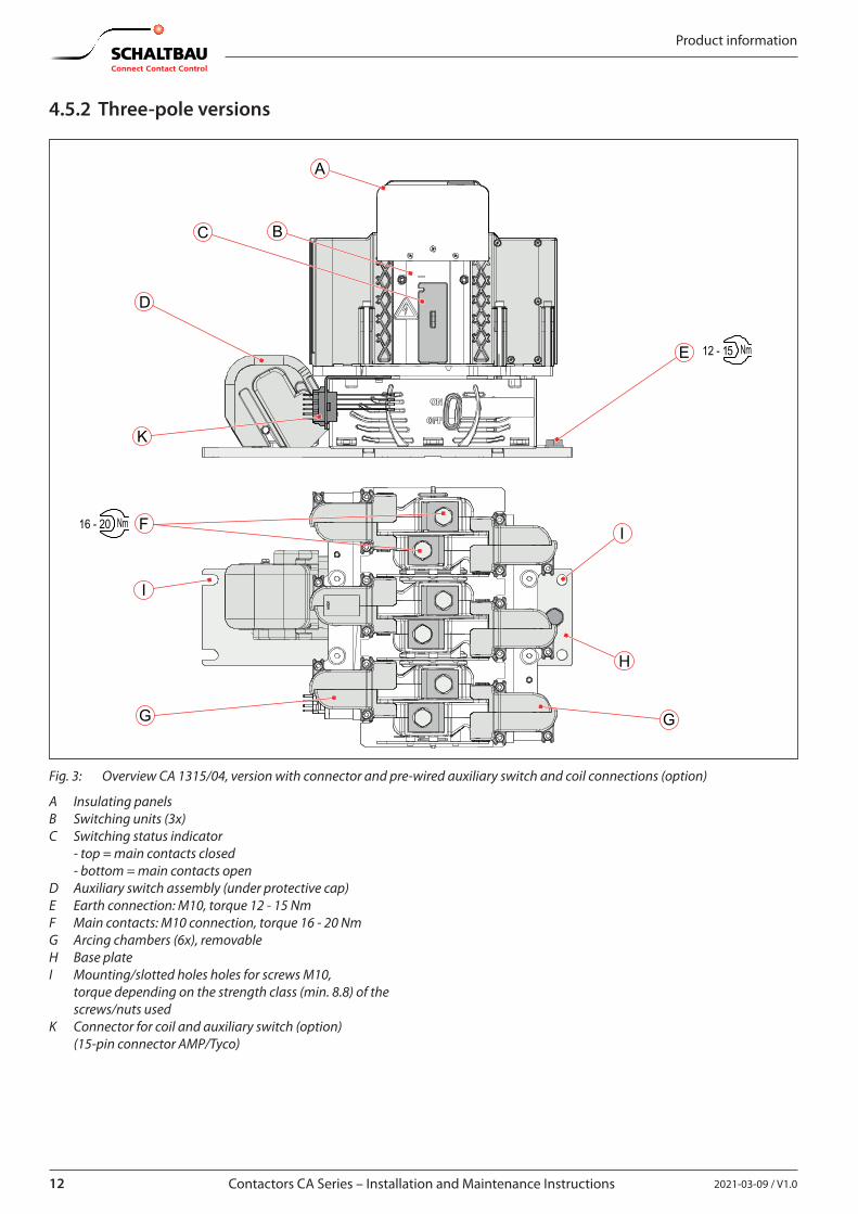
Fig. 3: Overview CA 1315/04, version with connector and pre-wired auxiliary switch and coil connections (option)
A Insulating panelsB Switching units (3x)C Switching status indicator - top = main contacts closed - bottom = main contacts openD Auxiliary switch assembly (under protective cap)E Earth connection: M10, torque 12 - 15 NmF Main contacts: M10 connection, torque 16 - 20 NmG Arcing chambers (6x), removableH Base plateI Mounting/slotted holes holes for screws M10,
torque depending on the strength class (min. 8.8) of the screws/nuts used
K Connector for coil and auxiliary switch (option) (15-pin connector AMP/Tyco)
132021-03-09 / V1.0 Contactors CA Series – Installation and Maintenance Instructions
Product information
I
H
D
E12 - 15 Nm
F
G
16 - 20 Nm
G
B
A
C
J
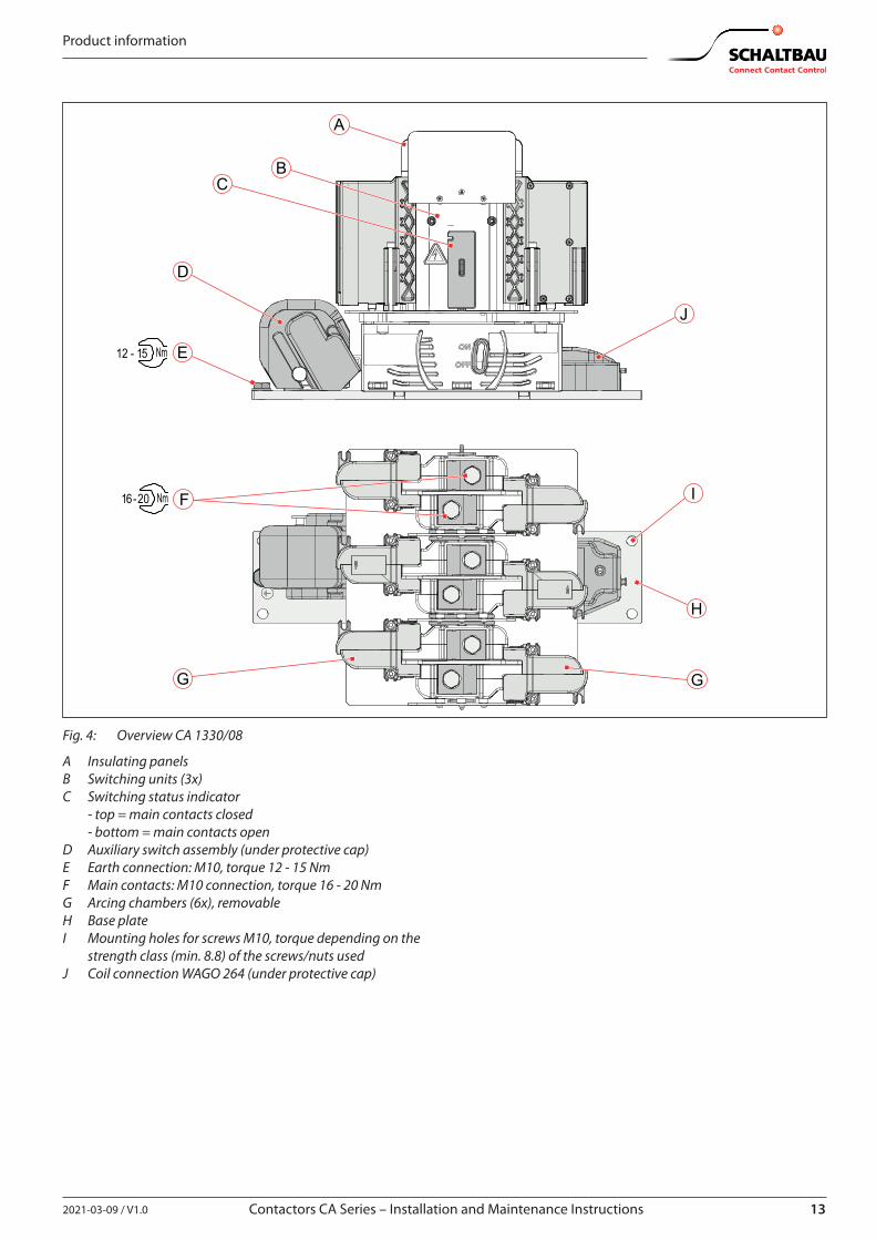
Fig. 4: Overview CA 1330/08
A Insulating panelsB Switching units (3x)C Switching status indicator - top = main contacts closed - bottom = main contacts openD Auxiliary switch assembly (under protective cap)E Earth connection: M10, torque 12 - 15 NmF Main contacts: M10 connection, torque 16 - 20 NmG Arcing chambers (6x), removableH Base plateI Mounting holes for screws M10, torque depending on the
strength class (min. 8.8) of the screws/nuts usedJ Coil connection WAGO 264 (under protective cap)
14 2021-03-09 / V1.0
Product information
Contactors CA Series – Installation and Maintenance Instructions
4.6 Function
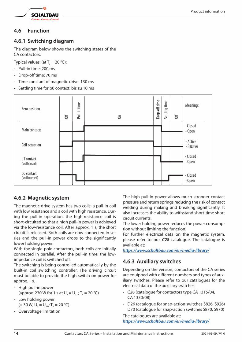
4.6.1 Switching diagramThe diagram below shows the switching states of the CA contactors.
Typical values: (at Ta = 20 °C): - Pull-in time: 200 ms - Drop-off time: 70 ms - Time constant of magnetic drive: 130 ms - Settling time for b0 contact: bis zu 10 ms
Zero position
O� Pull-
in tim
e
On Drop
-o�
time
Settl
ing ti
me
O�
Meaning:
Main contacts
Coil actuation
a1 contact(well closed)
b0 contact (well opened)
- Closed
- Open
- Closed- Open
- Closed- Open
- Active - Passive
4.6.2 Magnetic systemThe magnetic drive system has two coils: a pull-in coil with low resistance and a coil with high resistance. Dur-ing the pull-in operation, the high-resistance coil is short-circuited so that a high pull-in power is achieved via the low-resistance coil. After approx. 1 s, the short circuit is released. Both coils are now connected in se-ries and the pull-in power drops to the significantly lower holding power.With the single-pole contactors, both coils are initially connected in parallel. After the pull-in time, the low-impedance coil is switched off. The switching is being controlled automatically by the built-in coil switching controller. The driving circuit must be able to provide the high switch-on power for approx. 1 s. - High pull-in power
(approx. 230 W for 1 s at Us = Us n; Ta = 20 °C) - Low holding power
(< 30 W; Us = Us n; Ta = 20 °C) - Overvoltage limitation
The high pull-in power allows much stronger contact pressure and return springs reducing the risk of contact welding during making and breaking significantly. It also increases the ability to withstand short-time short circuit currents.The lower holding power reduces the power consump-tion without limiting the function.For further electrical data on the magnetic system, please refer to our C28 catalogue. The catalogue is available at:https://www.schaltbau.com/en/media-library/
4.6.3 Auxiliary switchesDepending on the version, contactors of the CA series are equipped with different numbers and types of aux-iliary switches. Please refer to our catalogues for the electrical data of the auxiliary switches: - C28 (catalogue for contactors type CA 1315/04,
CA 1330/08) - D26 (catalogue for snap-action switches S826, S926)
D70 (catalogue for snap-action switches S870, S970) The catalogues are available at: https://www.schaltbau.com/en/media-library/
152021-03-09 / V1.0 Contactors CA Series – Installation and Maintenance Instructions
Storage
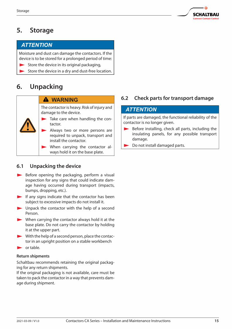
5. Storage
ATTENTIONMoisture and dust can damage the contactors. If the device is to be stored for a prolonged period of time:
X Store the device in its original packaging, X Store the device in a dry and dust-free location.
6. Unpacking
WARNINGThe contactor is heavy. Risk of injury and damage to the device.
X Take care when handling the con-tactor.
X Always two or more persons are required to unpack, transport and install the contactor.
X When carrying the contactor al-ways hold it on the base plate.
6.1 Unpacking the device
X Before opening the packaging, perform a visual inspection for any signs that could indicate dam-age having occurred during transport (impacts, bumps, dropping, etc.).
X If any signs indicate that the contactor has been subject to excessive impacts do not install it.
X Unpack the contactor with the help of a second Person.
X When carrying the contactor always hold it at the base plate. Do not carry the contactor by holding it at the upper part.
X With the help of a second person, place the contac-tor in an upright position on a stable workbench
X or table.
Return shipmentsSchaltbau recommends retaining the original packag-ing for any return shipments.If the original packaging is not available, care must be taken to pack the contactor in a way that prevents dam-age during shipment.
6.2 Check parts for transport damage
ATTENTIONIf parts are damaged, the functional reliability of the contactor is no longer given.
X Before installing, check all parts, including the insulating panels, for any possible transport damage.
X Do not install damaged parts.
16 2021-03-09 / V1.0
Installation
Contactors CA Series – Installation and Maintenance Instructions
7. Installation
7.1 Mounting
7.1.1 Dimensions/interfaces and further technical specifications
The dimensions and other technical specifications are given in the respective data sheets or can be found in our C28 catalogue. The catalogue is available under: https://www.schaltbau.com/en/media-library/
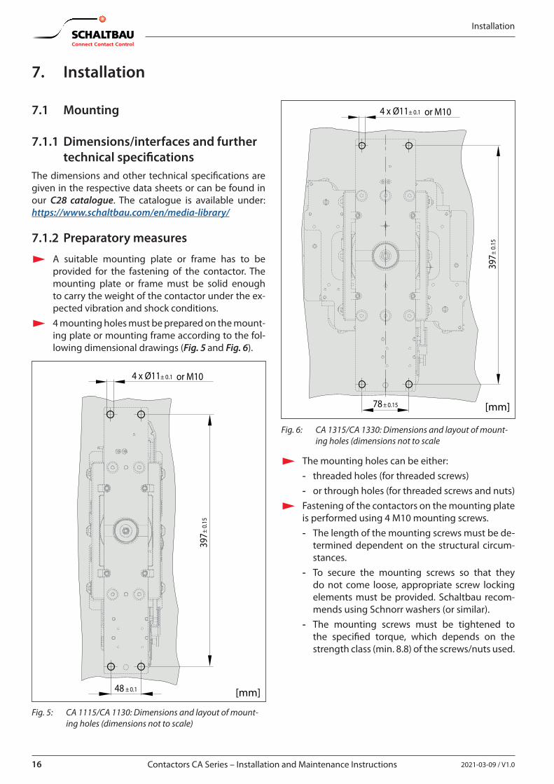
7.1.2 Preparatory measures
X A suitable mounting plate or frame has to be provided for the fastening of the contactor. The mounting plate or frame must be solid enough to carry the weight of the contactor under the ex-pected vibration and shock conditions.
X 4 mounting holes must be prepared on the mount-ing plate or mounting frame according to the fol-lowing dimensional drawings (Fig. 5 and Fig. 6).
[mm]
4 x or M10Ø11± 0.1
48 ± 0.1
397±
0.15
Fig. 5: CA 1115/CA 1130: Dimensions and layout of mount-ing holes (dimensions not to scale)
[mm]
4 x or M10Ø11± 0.1
397±
0.15
78 ± 0.15
Fig. 6: CA 1315/CA 1330: Dimensions and layout of mount-ing holes (dimensions not to scale
X The mounting holes can be either: - threaded holes (for threaded screws) - or through holes (for threaded screws and nuts)
X Fastening of the contactors on the mounting plate is performed using 4 M10 mounting screws. - The length of the mounting screws must be de-
termined dependent on the structural circum-stances.
- To secure the mounting screws so that they do not come loose, appropriate screw locking elements must be provided. Schaltbau recom-mends using Schnorr washers (or similar).
- The mounting screws must be tightened to the specified torque, which depends on the strength class (min. 8.8) of the screws/nuts used.
172021-03-09 / V1.0 Contactors CA Series – Installation and Maintenance Instructions
Installation
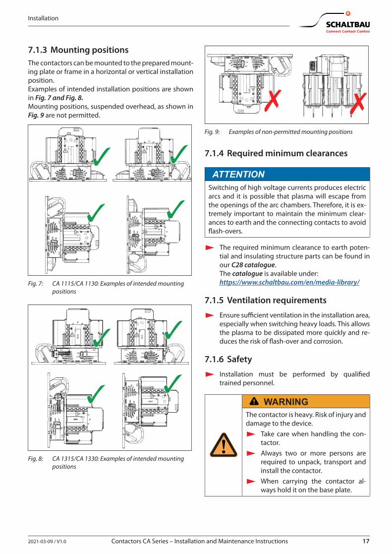
7.1.3 Mounting positionsThe contactors can be mounted to the prepared mount-ing plate or frame in a horizontal or vertical installation position.Examples of intended installation positions are shown in Fig. 7 and Fig. 8. Mounting positions, suspended overhead, as shown in Fig. 9 are not permitted.
Fig. 7: CA 1115/CA 1130: Examples of intended mounting positions
Fig. 8: CA 1315/CA 1330: Examples of intended mounting positions
Fig. 9: Examples of non-permitted mounting positions
7.1.4 Required minimum clearances
ATTENTIONSwitching of high voltage currents produces electric arcs and it is possible that plasma will escape from the openings of the arc chambers. Therefore, it is ex-tremely important to maintain the minimum clear-ances to earth and the connecting contacts to avoid flash-overs.
X The required minimum clearance to earth poten-tial and insulating structure parts can be found in our C28 catalogue. The catalogue is available under: https://www.schaltbau.com/en/media-library/
7.1.5 Ventilation requirements
X Ensure sufficient ventilation in the installation area, especially when switching heavy loads. This allows the plasma to be dissipated more quickly and re-duces the risk of flash-over and corrosion.
7.1.6 Safety
X Installation must be performed by qualified trained personnel.
WARNINGThe contactor is heavy. Risk of injury and damage to the device.
X Take care when handling the con-tactor.
X Always two or more persons are required to unpack, transport and install the contactor.
X When carrying the contactor al-ways hold it on the base plate.
18 2021-03-09 / V1.0
Installation
Contactors CA Series – Installation and Maintenance Instructions
ATTENTIONWhen installing, ensure that no dirt can get into the contactor as a result of surrounding building activities.
ATTENTIONDetent-edged rings and detent-edged washers have a limited life time. After screws secured with detent-edged rings or detent-edged washers have been undone three times, the rings or washers must be replaced by new ones.
X Record the frequency of undoing of the screws in the work log.
X Replace detent-edged rings or detent-edged washers with new ones after the screws have been undone three times.
7.1.7 Tools required
- Socket spanner set, hexagon nuts - Open-ended spanner set - Torque spanner
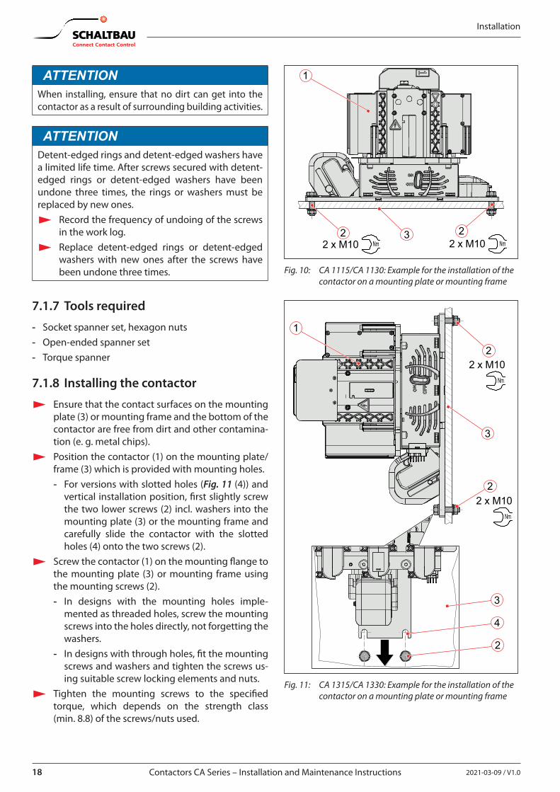
7.1.8 Installing the contactor
X Ensure that the contact surfaces on the mounting plate (3) or mounting frame and the bottom of the contactor are free from dirt and other contamina-tion (e. g. metal chips).
X Position the contactor (1) on the mounting plate/frame (3) which is provided with mounting holes. - For versions with slotted holes (Fig. 11 (4)) and
vertical installation position, first slightly screw the two lower screws (2) incl. washers into the mounting plate (3) or the mounting frame and carefully slide the contactor with the slotted holes (4) onto the two screws (2).
X Screw the contactor (1) on the mounting flange to the mounting plate (3) or mounting frame using the mounting screws (2). - In designs with the mounting holes imple-
mented as threaded holes, screw the mounting screws into the holes directly, not forgetting the washers.
- In designs with through holes, fit the mounting screws and washers and tighten the screws us-ing suitable screw locking elements and nuts.
X Tighten the mounting screws to the specified torque, which depends on the strength class (min. 8.8) of the screws/nuts used.
32
1
Nm2 x M102
Nm2 x M10
Fig. 10: CA 1115/CA 1130: Example for the installation of the contactor on a mounting plate or mounting frame
3
2
1
Nm
2 x M10
2
Nm
2 x M10
3
2
4
Fig. 11: CA 1315/CA 1330: Example for the installation of the contactor on a mounting plate or mounting frame
192021-03-09 / V1.0 Contactors CA Series – Installation and Maintenance Instructions
Installation
7.2 Electrical connection
7.2.1 Electrical data and other technical specifications
For the power consumption of the coil drive system and electrical data of the auxiliary switches as well as other technical specifications, refer to the respective data sheets and to our C28 catalogue. The catalogue is available under:https://www.schaltbau.com/en/media-library/
7.2.2 Preparatory measures
X The minimum clearances to live and earthed parts are given in the corresponding data sheets or in our C28 catalogue and must be adhered to. The catalogue is available under:https://www.schaltbau.com/en/media-library/
X Switching of high voltage currents produces elec-tric arcs and it is possible that plasma will escape from the openings of the arcing chambers. There-fore, it is extremely important to maintain the min-imum clearances to live and earthed parts to avoid flashovers. These minimum clearances have been tested and specified in relation to the switching capacity of the contactors.
X For switching heavy loads allow a minimum time of 20 s between two switchings. Allow a recovery time of at least 10 min after 3 heavy load switch-ings in succession.
X The earth connecting cable must be fitted with an appropriate ring terminal (for M10 terminal screw).
X Undersized conductor cross-sections for the earth connection may produce a safety hazard.
X The minimum conductor cross-sections for the main terminal connection and the earth connec-tion must be observed.
X If connecting cables are used for the main power circuit, they must be selected taking into consid-eration the insulation class and the ambient con-ditions.
X If connecting cables are used for the main power circuit, they must be fitted with appropriate ring terminals (for M10 terminal screws).
X To secure the main terminal screws so that they do not come loose, appropriate screw locking ele-ments must be provided. Schaltbau recommends using Schnorr washers (or similar).
X The main terminal screws must be tightened to a torque of 16 - 20 Nm.
For pre-wired versions with connection plug/socket:
X An appropriately assembled external connector must be prepared for connecting the control wires (auxiliary switch and coil connections) to the exist-ing plug at the contactor.
For non-pre-wired versions without connection plug/socket:
X Depending on the version, the auxiliary switches are either provided with flat plug or screw termi-nals (M3). In the case of flat plug terminals, the control wires must be equipped with corresponding flat recep-tacles (6.3 x 0.8 mm):
X The maximum permissible cross-section for the auxiliary switch control wires is 1 mm2 / AWG 18 stranded wire.
X The control wires for the coil connection are con-nected with cage clamp terminals and must be stripped accordingly for this purpose (if necessary, fit with appropriate wire end sleeves).
20 2021-03-09 / V1.0
Installation
Contactors CA Series – Installation and Maintenance Instructions
7.2.3 Safety
DANGERThe contactors are used for high voltage switching. Contact with live electrical parts can result in serious injuries or even death! Live parts are all metal parts belonging directly to one of the circuits or wires connecting to them. All other visible metal parts and wiring may also be live if a fault exists.Before starting any work on the contactors, always comply with the following safety rules:
X Disconnect on all sides X Secure to prevent switching back on X Clearly identify the working area X Check that a voltage-free state exists X Earth and short circuit; this includes discharging any capacitors in the main circuit X Beside the main power circuits, also disconnect additional and auxiliary circuits X Cover or insulate adjacent live parts X The presence of a voltage-free state can only be clearly identified by a qualified electrician. X When the work has been concluded, follow the procedure in reverse.
ATTENTIONDetent-edged rings and detent-edged washers have a limited life time. After screws secured with detent-edged rings or detent-edged washers have been undone three times, the rings or washers must be replaced by new ones.
X Record the frequency of undoing of the screws in the work log. X Replace detent-edged rings or detent-edged washers with new ones after the screws have been undone
three times.
7.2.4 Tools required
- Set of slotted screwdrivers - Torque spanner - Continuity tester - Cable ties
212021-03-09 / V1.0 Contactors CA Series – Installation and Maintenance Instructions
Installation
7.2.5 Connecting the auxiliary switchesDepending on the type and design of the contactor and the auxiliary switches used, the auxiliary switches are connected - either with a factory-pre-assembled plug-in connector - or with screw terminals - or with flat tap terminals
DANGERThe protective cap covering the auxiliary switches is part of the insulation system. Operation of the contactors without the protective cap may result in serious inju-ries or even death!
X Never operate the contactors with-out the protective cap.
X When removing the protective cap during installation or maintenance works, make sure that the protec-tive cap is re-installed before the contactors are put into service.
ATTENTIONMake sure that according to the insulation coordina-tion there is sufficient clearance between the wires of the control voltage and the main connections.
ATTENTION X The maximum permissible conductor cross-
section of the auxiliary contact control wires is 1 mm2 / AWG 18 stranded wire.
X Bending of the connection terminals on the auxiliary switches is not permitted!
X Move and route the control wires and recepta-cles only in the direction of plugging.
X Mechanically secure the control wires to mini-mise feedback effects of forces caused by the wires (e. g. shock, vibrations) acting on the terminals.
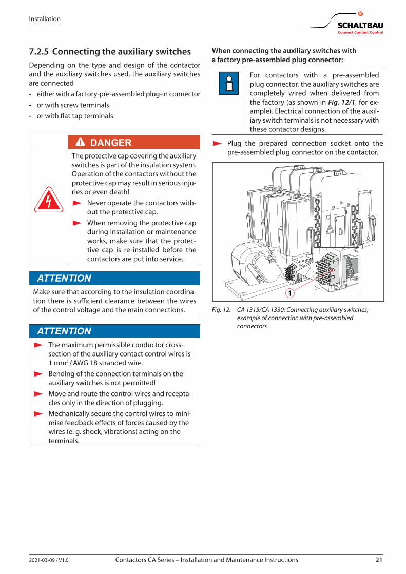
When connecting the auxiliary switches with a factory pre-assembled plug connector:
For contactors with a pre-assembled plug connector, the auxiliary switches are completely wired when delivered from the factory (as shown in Fig. 12/1, for ex-ample). Electrical connection of the auxil-iary switch terminals is not necessary with these contactor designs.
X Plug the prepared connection socket onto the pre-assembled plug connector on the contactor.
1
Fig. 12: CA 1315/CA 1330: Connecting auxiliary switches, example of connection with pre-assembled connectors
22 2021-03-09 / V1.0
Installation
Contactors CA Series – Installation and Maintenance Instructions
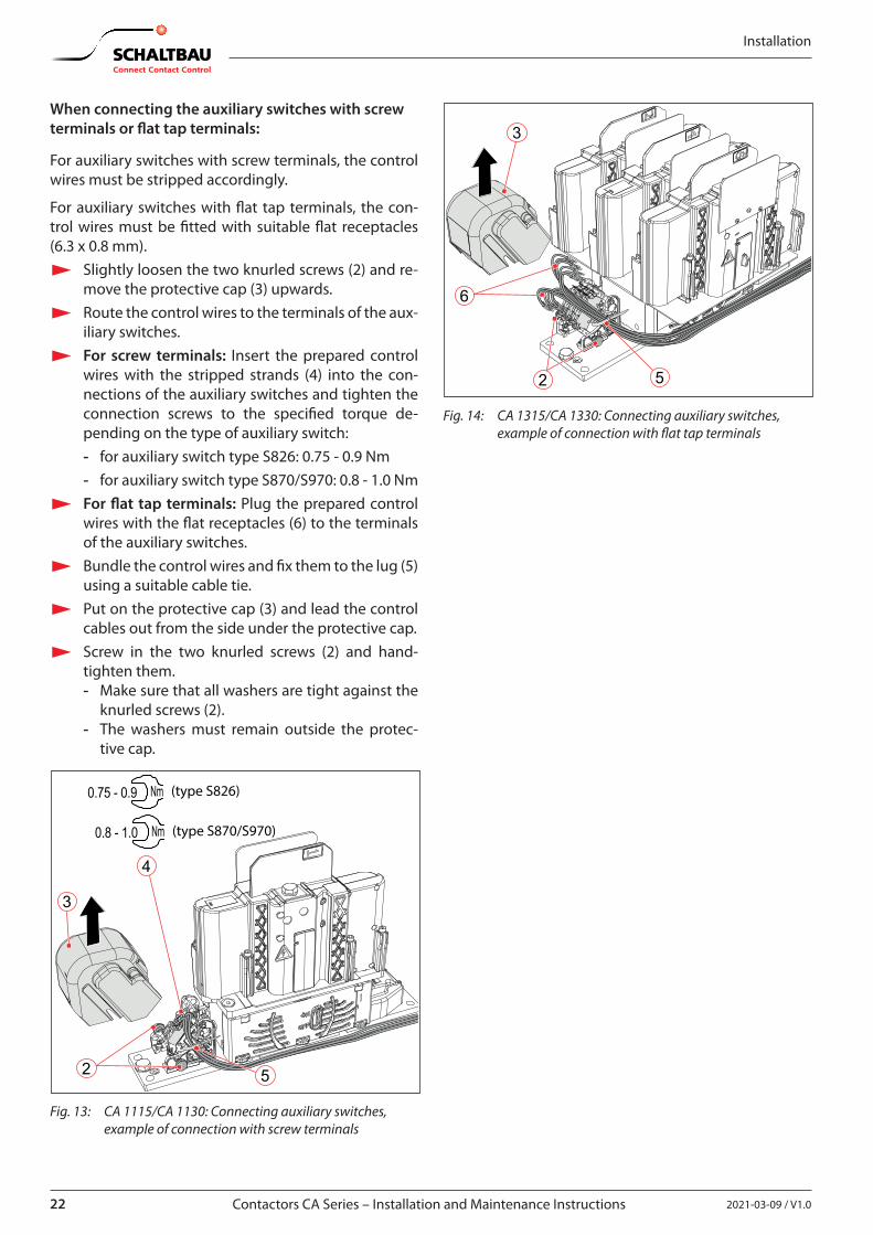
When connecting the auxiliary switches with screw terminals or flat tap terminals:
For auxiliary switches with screw terminals, the control wires must be stripped accordingly.
For auxiliary switches with flat tap terminals, the con-trol wires must be fitted with suitable flat receptacles (6.3 x 0.8 mm).
X Slightly loosen the two knurled screws (2) and re-move the protective cap (3) upwards.
X Route the control wires to the terminals of the aux-iliary switches.
X For screw terminals: Insert the prepared control wires with the stripped strands (4) into the con-nections of the auxiliary switches and tighten the connection screws to the specified torque de-pending on the type of auxiliary switch: - for auxiliary switch type S826: 0.75 - 0.9 Nm - for auxiliary switch type S870/S970: 0.8 - 1.0 Nm
X For flat tap terminals: Plug the prepared control wires with the flat receptacles (6) to the terminals of the auxiliary switches.
X Bundle the control wires and fix them to the lug (5) using a suitable cable tie.
X Put on the protective cap (3) and lead the control cables out from the side under the protective cap.
X Screw in the two knurled screws (2) and hand-tighten them. - Make sure that all washers are tight against the
knurled screws (2). - The washers must remain outside the protec-
tive cap.
4
3
2 5
0.75 - 0.9 Nm (type S826)
0.8 - 1.0 Nm (type S870/S970)
Fig. 13: CA 1115/CA 1130: Connecting auxiliary switches, example of connection with screw terminals
2
3
6
5
Fig. 14: CA 1315/CA 1330: Connecting auxiliary switches, example of connection with flat tap terminals
232021-03-09 / V1.0 Contactors CA Series – Installation and Maintenance Instructions
Installation
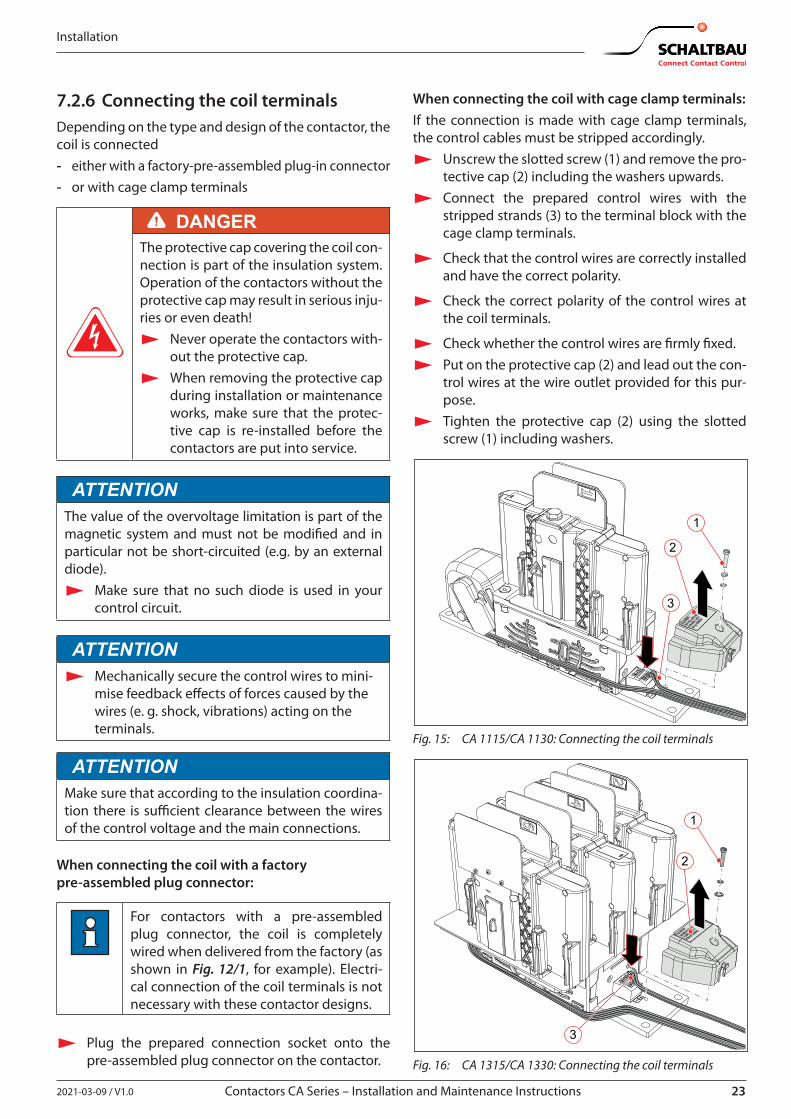
7.2.6 Connecting the coil terminalsDepending on the type and design of the contactor, the coil is connected - either with a factory-pre-assembled plug-in connector - or with cage clamp terminals
DANGERThe protective cap covering the coil con-nection is part of the insulation system. Operation of the contactors without the protective cap may result in serious inju-ries or even death!
X Never operate the contactors with-out the protective cap.
X When removing the protective cap during installation or maintenance works, make sure that the protec-tive cap is re-installed before the contactors are put into service.
ATTENTIONThe value of the overvoltage limitation is part of the magnetic system and must not be modified and in particular not be short-circuited (e.g. by an external diode).
X Make sure that no such diode is used in your control circuit.
ATTENTION X Mechanically secure the control wires to mini-
mise feedback effects of forces caused by the wires (e. g. shock, vibrations) acting on the terminals.
ATTENTIONMake sure that according to the insulation coordina-tion there is sufficient clearance between the wires of the control voltage and the main connections.
When connecting the coil with a factory pre-assembled plug connector:
For contactors with a pre-assembled plug connector, the coil is completely wired when delivered from the factory (as shown in Fig. 12/1, for example). Electri-cal connection of the coil terminals is not necessary with these contactor designs.
X Plug the prepared connection socket onto the pre-assembled plug connector on the contactor.
When connecting the coil with cage clamp terminals:If the connection is made with cage clamp terminals, the control cables must be stripped accordingly.
X Unscrew the slotted screw (1) and remove the pro-tective cap (2) including the washers upwards.
X Connect the prepared control wires with the stripped strands (3) to the terminal block with the cage clamp terminals.
X Check that the control wires are correctly installed and have the correct polarity.
X Check the correct polarity of the control wires at the coil terminals.
X Check whether the control wires are firmly fixed. X Put on the protective cap (2) and lead out the con-
trol wires at the wire outlet provided for this pur-pose.
X Tighten the protective cap (2) using the slotted screw (1) including washers.
3
1
2
Fig. 15: CA 1115/CA 1130: Connecting the coil terminals
3
1
2
Fig. 16: CA 1315/CA 1330: Connecting the coil terminals
24 2021-03-09 / V1.0
Installation
Contactors CA Series – Installation and Maintenance Instructions
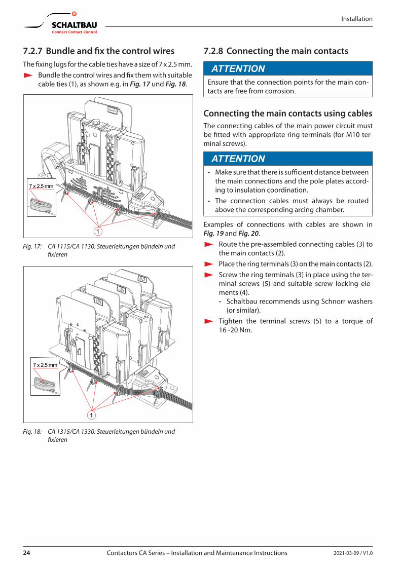
7.2.7 Bundle and fix the control wiresThe fixing lugs for the cable ties have a size of 7 x 2.5 mm.
X Bundle the control wires and fix them with suitable cable ties (1), as shown e.g. in Fig. 17 und Fig. 18.
7 x 2.5 mm
1
Fig. 17: CA 1115/CA 1130: Steuerleitungen bündeln und fixieren
7 x 2.5 mm
1
Fig. 18: CA 1315/CA 1330: Steuerleitungen bündeln und fixieren
7.2.8 Connecting the main contacts
ATTENTIONEnsure that the connection points for the main con-tacts are free from corrosion.
Connecting the main contacts using cablesThe connecting cables of the main power circuit must be fitted with appropriate ring terminals (for M10 ter-minal screws).
ATTENTION - Make sure that there is sufficient distance between
the main connections and the pole plates accord-ing to insulation coordination.
- The connection cables must always be routed above the corresponding arcing chamber.
Examples of connections with cables are shown in Fig. 19 and Fig. 20.
X Route the pre-assembled connecting cables (3) to the main contacts (2).
X Place the ring terminals (3) on the main contacts (2). X Screw the ring terminals (3) in place using the ter-
minal screws (5) and suitable screw locking ele-ments (4). - Schaltbau recommends using Schnorr washers
(or similar). X Tighten the terminal screws (5) to a torque of
16 -20 Nm.
252021-03-09 / V1.0 Contactors CA Series – Installation and Maintenance Instructions
Installation
16 - 20 Nm
23
4
5
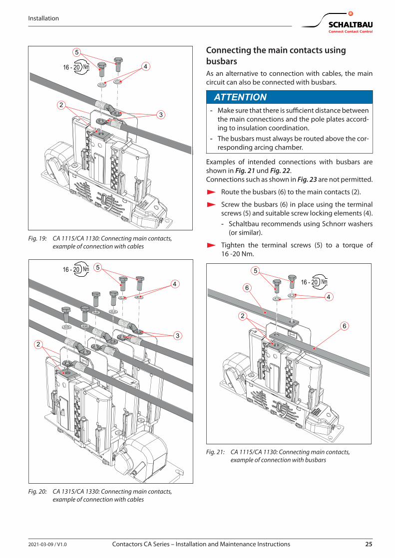
Fig. 19: CA 1115/CA 1130: Connecting main contacts, example of connection with cables
16 - 20 Nm
23
4
5
Fig. 20: CA 1315/CA 1330: Connecting main contacts, example of connection with cables
Connecting the main contacts using busbarsAs an alternative to connection with cables, the main circuit can also be connected with busbars.
ATTENTION - Make sure that there is sufficient distance between
the main connections and the pole plates accord-ing to insulation coordination.
- The busbars must always be routed above the cor-responding arcing chamber.
Examples of intended connections with busbars are shown in Fig. 21 und Fig. 22.Connections such as shown in Fig. 23 are not permitted.
X Route the busbars (6) to the main contacts (2).
X Screw the busbars (6) in place using the terminal screws (5) and suitable screw locking elements (4). - Schaltbau recommends using Schnorr washers
(or similar).
X Tighten the terminal screws (5) to a torque of 16 -20 Nm.
16 - 20 Nm
26
5
46
Fig. 21: CA 1115/CA 1130: Connecting main contacts, example of connection with busbars
26 2021-03-09 / V1.0
Installation
Contactors CA Series – Installation and Maintenance Instructions
16 - 20 Nm
2
4
5
6
6
2
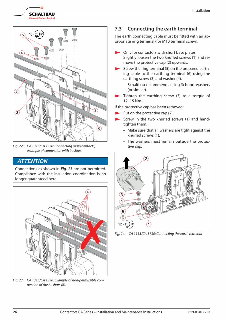
Fig. 22: CA 1315/CA 1330: Connecting main contacts, example of connection with busbars
ATTENTIONConnections as shown in Fig. 23 are not permitted. Compliance with the insulation coordination is no longer guaranteed here.
6
Fig. 23: CA 1315/CA 1330: Example of non-permissible con-nection of the busbars (6).
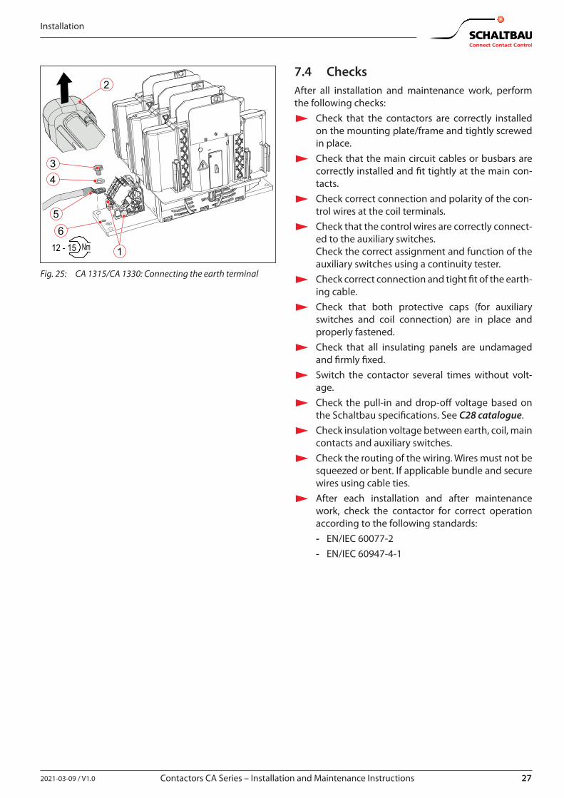
7.3 Connecting the earth terminalThe earth connecting cable must be fitted with an ap-propriate ring terminal (for M10 terminal screw).
X Only for contactors with short base plates: Slightly loosen the two knurled screws (1) and re-move the protective cap (2) upwards.
X Screw the ring terminal (5) on the prepared earth-ing cable to the earthing terminal (6) using the earthing screw (3) and washer (4). - Schaltbau recommends using Schnorr washers
(or similar). X Tighten the earthing screw (3) to a torque of
12 -15 Nm.If the protective cap has been removed:
X Put on the protective cap (2). X Screw in the two knurled screws (1) and hand-
tighten them. - Make sure that all washers are tight against the
knurled screws (1). - The washers must remain outside the protec-
tive cap.
12 - 15 Nm
2
34
56
1
Fig. 24: CA 1115/CA 1130: Connecting the earth terminal
272021-03-09 / V1.0 Contactors CA Series – Installation and Maintenance Instructions
Installation
12 - 15 Nm
2
34
56
1
Fig. 25: CA 1315/CA 1330: Connecting the earth terminal
7.4 ChecksAfter all installation and maintenance work, perform the following checks:
X Check that the contactors are correctly installed on the mounting plate/frame and tightly screwed in place.
X Check that the main circuit cables or busbars are correctly installed and fit tightly at the main con-tacts.
X Check correct connection and polarity of the con-trol wires at the coil terminals.
X Check that the control wires are correctly connect-ed to the auxiliary switches.Check the correct assignment and function of the auxiliary switches using a continuity tester.
X Check correct connection and tight fit of the earth-ing cable.
X Check that both protective caps (for auxiliary switches and coil connection) are in place and properly fastened.
X Check that all insulating panels are undamaged and firmly fixed.
X Switch the contactor several times without volt-age.
X Check the pull-in and drop-off voltage based on the Schaltbau specifications. See C28 catalogue.
X Check insulation voltage between earth, coil, main contacts and auxiliary switches.
X Check the routing of the wiring. Wires must not be squeezed or bent. If applicable bundle and secure wires using cable ties.
X After each installation and after maintenance work, check the contactor for correct operation according to the following standards: - EN/IEC 60077-2 - EN/IEC 60947-4-1
28 2021-03-09 / V1.0
Maintenance
Contactors CA Series – Installation and Maintenance Instructions
8. MaintenanceNote the expert knowledge which is essential for carry-ing out maintenance work, which is referred to in chap-ter “2. General and safety information”.
8.1 Safety
DANGERThe contactors are used for high voltage switching. Contact with live electrical parts can result in serious injuries or even death! Live parts are all metal parts belonging directly to one of the circuits or wires connecting to them. All other visible metal parts and wiring may also be live if a fault exists.Before starting any work on the contactors, always comply with the following safety rules:
X Disconnect on all sides X Secure to prevent switching back on X Clearly identify the working area X Check that a voltage-free state exists X Earth and short circuit; this includes discharging any capacitors in the main circuit X Beside the main power circuits, also disconnect additional and auxiliary circuits X Cover or insulate adjacent live parts X The presence of a voltage-free state can only be clearly identified by a qualified electrician. X When the work has been concluded, follow the procedure in reverse.
8.2 Preventive maintenanceContactors of the CA series are maintenance-free with-in the rated mechanical life time. The electrical life time depends on the number of switching cycles under heavy load conditions and may vary for different ap-plications. In normal use, this corresponds to a decade-long operating period.
8.2.1 Intervals for regular tests/checksTo ensure the correct function and a prolonged opera-tional life span of the contactors, the following checks and maintenance must be regularly performed.
Test/check Interval
External visual inspection of the contactor
X 1x per year
Check of the main contacts X 1x to 2x per year
Check of the auxiliary switches X Every 2 years
If the contactors are operated in a particularly dirty environment, the visual checks should be performed at shorter intervals. Dirt can impair the clearance and creepage distances, which can result in a shorter ser-vice life or to a malfunction..Unscheduled checks are only required if there have been a significant number of switching operations un-der short-circuit conditions.
DANGERIf damage to the contactor, cables or busbars is visible, the safety of the con-tactor is no longer guaranteed.Immediately submit any damaged con-tactors or components for maintenance.
292021-03-09 / V1.0 Contactors CA Series – Installation and Maintenance Instructions
Maintenance
ATTENTIONDetent-edged rings and detent-edged washers have a limited life time. After screws secured with detent-edged rings or detent-edged washers have been undone three times, the rings or washers must be replaced by new ones.
X Record the frequency of undoing of the screws in the work log.
X Replace detent-edged rings or detent-edged washers with new ones after the screws have been undone three times.
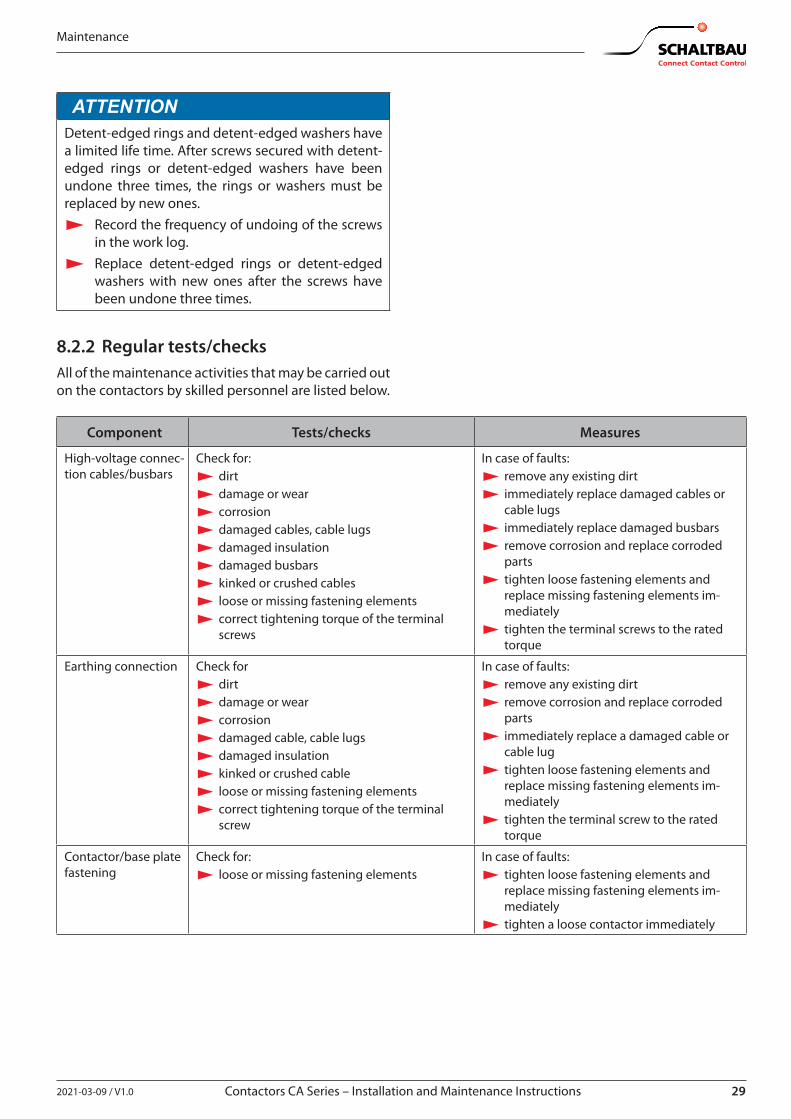
8.2.2 Regular tests/checksAll of the maintenance activities that may be carried out on the contactors by skilled personnel are listed below.
Component Tests/checks Measures
High-voltage connec-tion cables/busbars
Check for: X dirt X damage or wear X corrosion X damaged cables, cable lugs X damaged insulation X damaged busbars X kinked or crushed cables X loose or missing fastening elements X correct tightening torque of the terminal screws
In case of faults: X remove any existing dirt X immediately replace damaged cables or cable lugs X immediately replace damaged busbars X remove corrosion and replace corroded parts X tighten loose fastening elements and replace missing fastening elements im-mediately X tighten the terminal screws to the rated torque
Earthing connection Check for X dirt X damage or wear X corrosion X damaged cable, cable lugs X damaged insulation X kinked or crushed cable X loose or missing fastening elements X correct tightening torque of the terminal screw
In case of faults: X remove any existing dirt X remove corrosion and replace corroded parts X immediately replace a damaged cable or cable lug X tighten loose fastening elements and replace missing fastening elements im-mediately X tighten the terminal screw to the rated torque
Contactor/base plate fastening
Check for: X loose or missing fastening elements
In case of faults: X tighten loose fastening elements and replace missing fastening elements im-mediately X tighten a loose contactor immediately
30 2021-03-09 / V1.0
Maintenance
Contactors CA Series – Installation and Maintenance Instructions
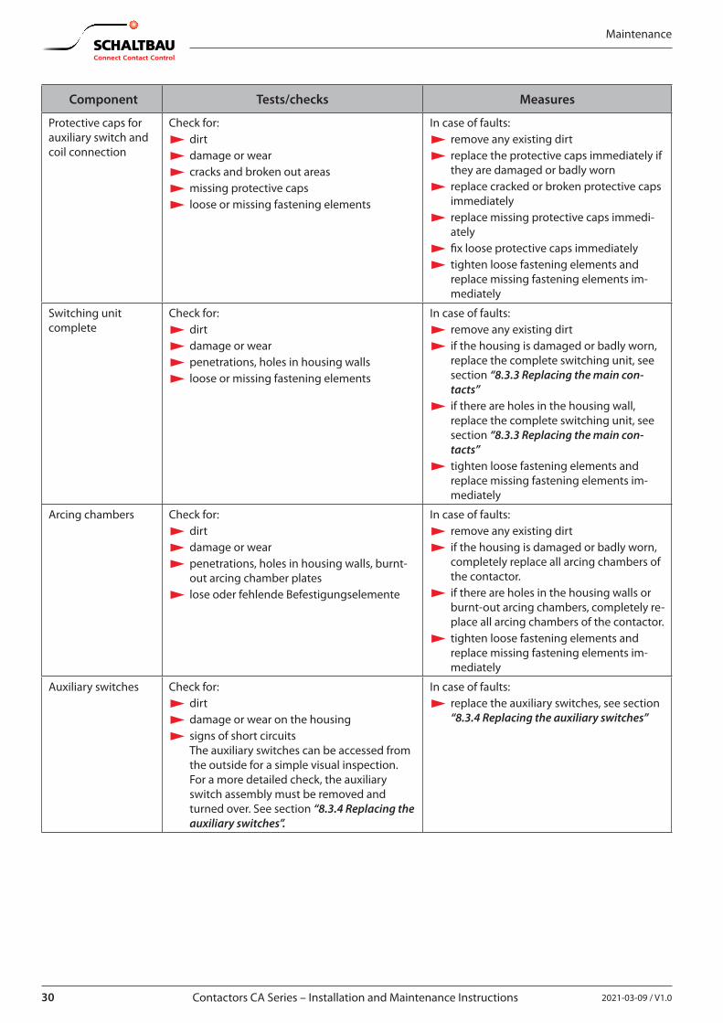
Component Tests/checks Measures
Protective caps for auxiliary switch and coil connection
Check for: X dirt X damage or wear X cracks and broken out areas X missing protective caps X loose or missing fastening elements
In case of faults: X remove any existing dirt X replace the protective caps immediately if they are damaged or badly worn X replace cracked or broken protective caps immediately X replace missing protective caps immedi-ately X fix loose protective caps immediately X tighten loose fastening elements and replace missing fastening elements im-mediately
Switching unit complete
Check for: X dirt X damage or wear X penetrations, holes in housing walls X loose or missing fastening elements
In case of faults: X remove any existing dirt X if the housing is damaged or badly worn, replace the complete switching unit, see section “8.3.3 Replacing the main con-tacts” X if there are holes in the housing wall, replace the complete switching unit, see section “8.3.3 Replacing the main con-tacts” X tighten loose fastening elements and replace missing fastening elements im-mediately
Arcing chambers Check for: X dirt X damage or wear X penetrations, holes in housing walls, burnt-out arcing chamber plates X lose oder fehlende Befestigungselemente
In case of faults: X remove any existing dirt X if the housing is damaged or badly worn, completely replace all arcing chambers of the contactor. X if there are holes in the housing walls or burnt-out arcing chambers, completely re-place all arcing chambers of the contactor. X tighten loose fastening elements and replace missing fastening elements im-mediately
Auxiliary switches Check for: X dirt X damage or wear on the housing X signs of short circuitsThe auxiliary switches can be accessed from the outside for a simple visual inspection.For a more detailed check, the auxiliary switch assembly must be removed and turned over. See section “8.3.4 Replacing the auxiliary switches”.
In case of faults: X replace the auxiliary switches, see section “8.3.4 Replacing the auxiliary switches”
312021-03-09 / V1.0 Contactors CA Series – Installation and Maintenance Instructions
Maintenance
Component Tests/checks Measures
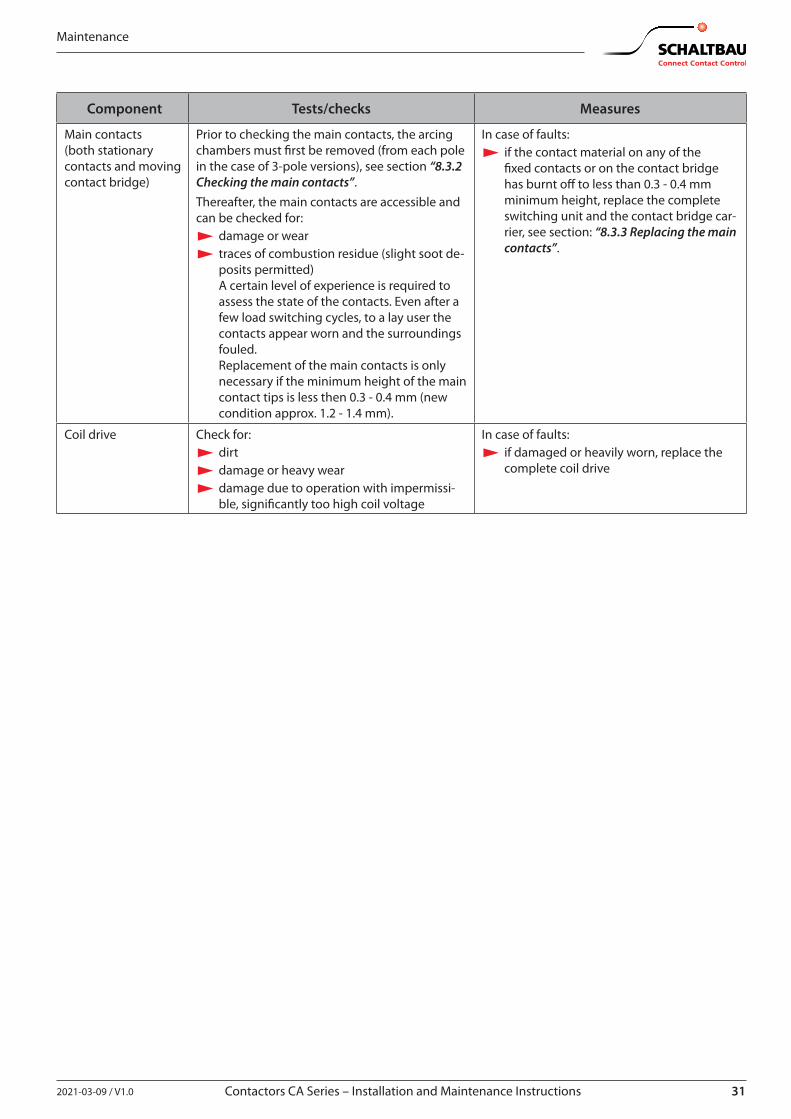
Main contacts(both stationary contacts and moving contact bridge)
Prior to checking the main contacts, the arcing chambers must first be removed (from each pole in the case of 3-pole versions), see section “8.3.2 Checking the main contacts”.Thereafter, the main contacts are accessible and can be checked for:
X damage or wear X traces of combustion residue (slight soot de-posits permitted)A certain level of experience is required to assess the state of the contacts. Even after a few load switching cycles, to a lay user the contacts appear worn and the surroundings fouled. Replacement of the main contacts is only necessary if the minimum height of the main contact tips is less then 0.3 - 0.4 mm (new condition approx. 1.2 - 1.4 mm).
In case of faults: X if the contact material on any of the fixed contacts or on the contact bridge has burnt off to less than 0.3 - 0.4 mm minimum height, replace the complete switching unit and the contact bridge car-rier, see section: “8.3.3 Replacing the main contacts”.
Coil drive Check for: X dirt X damage or heavy wear X damage due to operation with impermissi-ble, significantly too high coil voltage
In case of faults: X if damaged or heavily worn, replace the complete coil drive
32 2021-03-09 / V1.0
Maintenance
Contactors CA Series – Installation and Maintenance Instructions
8.3 Corrective maintenanceThe contactors are largely maintenance-free. Therefore there is no general requirement to replace parts during its service life.However, if an excessive number of emergency switch-ings, or damage has occurred during operation, Schalt-bau offers original spare parts.
WARNINGThe use of unsuitable parts can lead to accidents and serious personal injury due to malfunctions.
X Only use original spare parts! X Do not combine individual parts
from different contactors!
8.3.1 Replacing the arcing chambersArcing chambers only need to be replaced if they are damaged or the arcing plates are burnt out (only oc-curs with very many load switchings under short-circuit conditions).Always replace all arcing chambers completely: - for 1-pole versions all 2 arcing chambers - for 3-pole versions all 6 arcing chambers
Spare parts required - Arcing chamber complete, with arcing plates (2 units
per pole), see chapter “9. Spare parts”.
Tools required - Set of hexagon socket spanners - Torque spanner
Preconditions - The main contact connections (cables or busbars)
are removed, see section “7.2.8 Connecting the main contacts”.
Disassemble the arcing chambers
DANGERBefore beginning any work on the con-tactors, make sure that
X there is no voltage present, X all safety regulations are fully ob-
served. X Be sure to observe section
“8.1 Safety”.
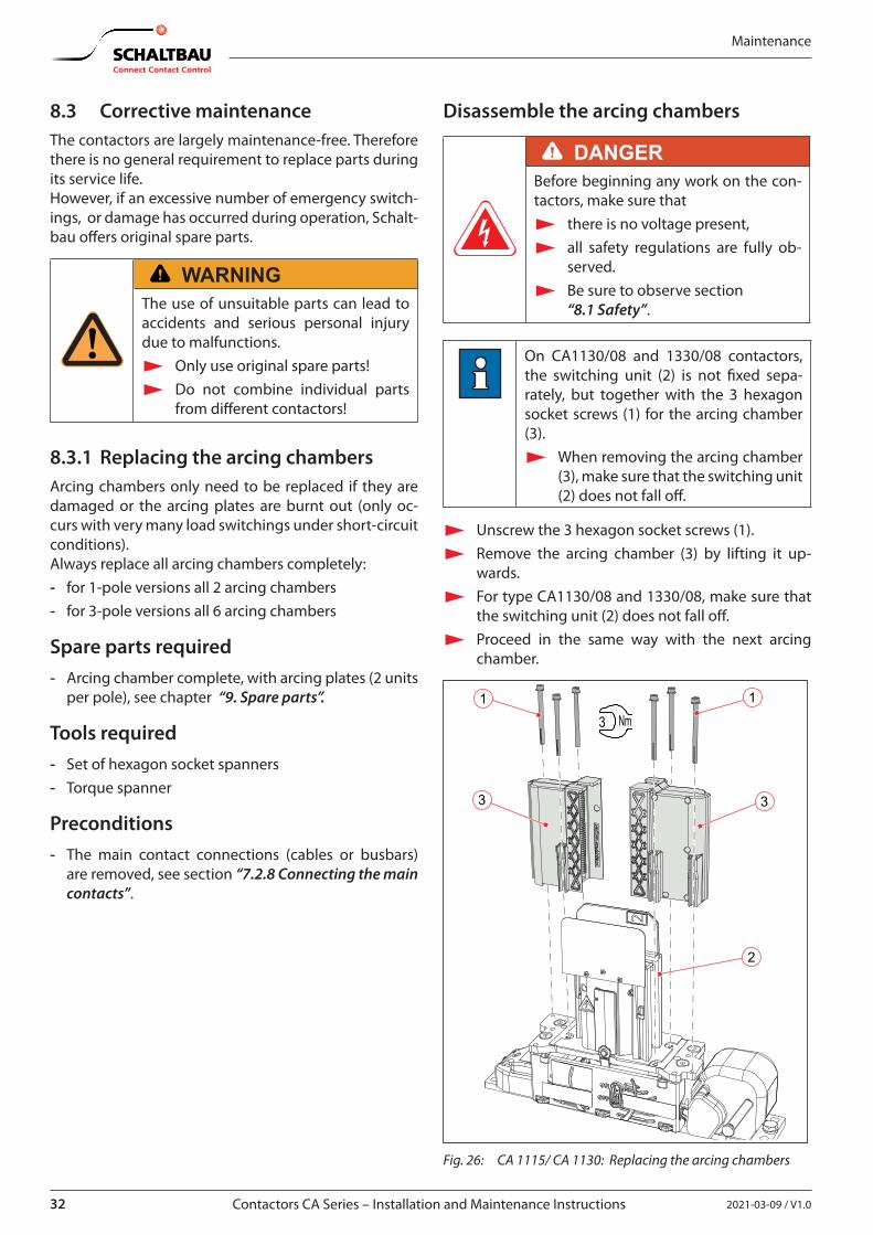
On CA1130/08 and 1330/08 contactors, the switching unit (2) is not fixed sepa-rately, but together with the 3 hexagon socket screws (1) for the arcing chamber (3).
X When removing the arcing chamber (3), make sure that the switching unit (2) does not fall off.
X Unscrew the 3 hexagon socket screws (1). X Remove the arcing chamber (3) by lifting it up-
wards. X For type CA1130/08 and 1330/08, make sure that
the switching unit (2) does not fall off. X Proceed in the same way with the next arcing
chamber.
3
1 1
3
3 Nm
2
Fig. 26: CA 1115/ CA 1130: Replacing the arcing chambers
332021-03-09 / V1.0 Contactors CA Series – Installation and Maintenance Instructions
Maintenance
31
3
1
1
13
3
3 Nm
2
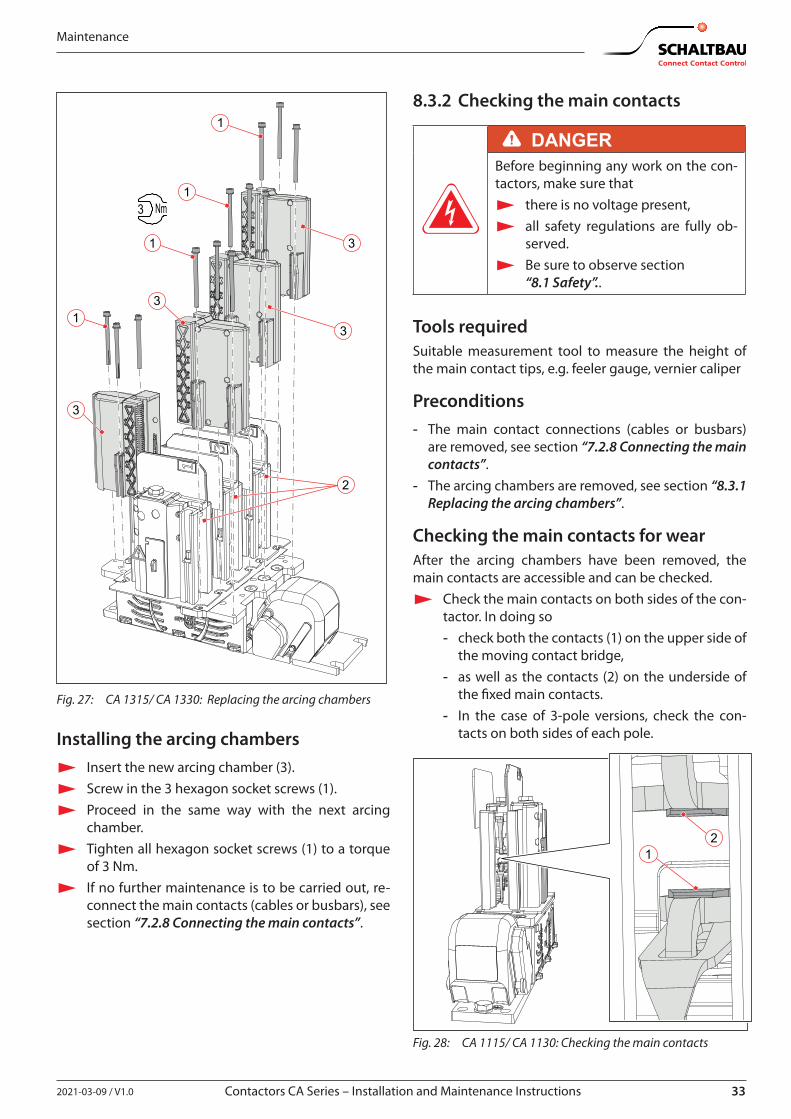
Fig. 27: CA 1315/ CA 1330: Replacing the arcing chambers
Installing the arcing chambers X Insert the new arcing chamber (3). X Screw in the 3 hexagon socket screws (1). X Proceed in the same way with the next arcing
chamber. X Tighten all hexagon socket screws (1) to a torque
of 3 Nm. X If no further maintenance is to be carried out, re-
connect the main contacts (cables or busbars), see section “7.2.8 Connecting the main contacts”.
8.3.2 Checking the main contacts
DANGERBefore beginning any work on the con-tactors, make sure that
X there is no voltage present, X all safety regulations are fully ob-
served. X Be sure to observe section
“8.1 Safety”..
Tools requiredSuitable measurement tool to measure the height of the main contact tips, e.g. feeler gauge, vernier caliper
Preconditions - The main contact connections (cables or busbars)
are removed, see section “7.2.8 Connecting the main contacts”.
- The arcing chambers are removed, see section “8.3.1 Replacing the arcing chambers”.
Checking the main contacts for wearAfter the arcing chambers have been removed, the main contacts are accessible and can be checked.
X Check the main contacts on both sides of the con-tactor. In doing so - check both the contacts (1) on the upper side of
the moving contact bridge, - as well as the contacts (2) on the underside of
the fixed main contacts. - In the case of 3-pole versions, check the con-
tacts on both sides of each pole.
21
Fig. 28: CA 1115/ CA 1130: Checking the main contacts
34 2021-03-09 / V1.0
Maintenance
Contactors CA Series – Installation and Maintenance Instructions
21
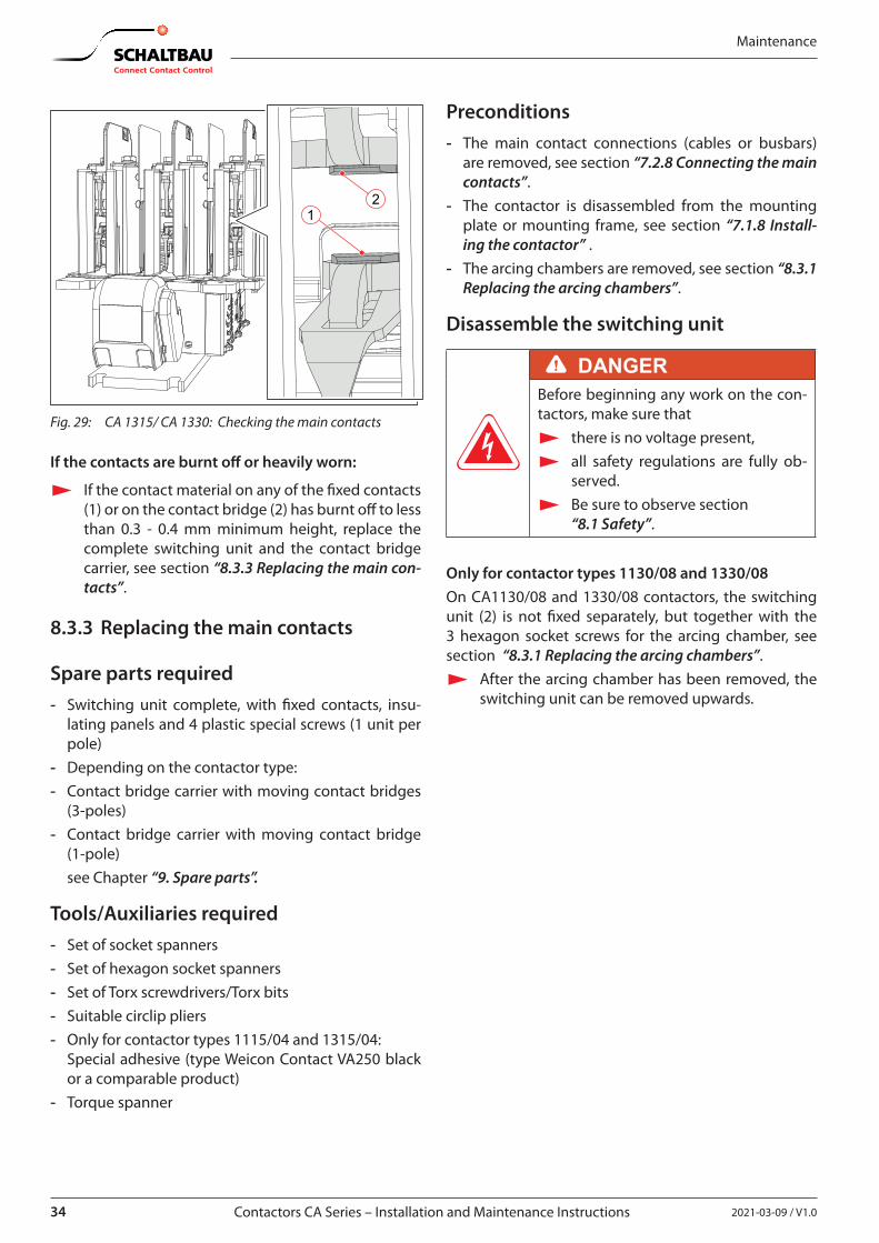
Fig. 29: CA 1315/ CA 1330: Checking the main contacts
If the contacts are burnt off or heavily worn:
X If the contact material on any of the fixed contacts (1) or on the contact bridge (2) has burnt off to less than 0.3 - 0.4 mm minimum height, replace the complete switching unit and the contact bridge carrier, see section “8.3.3 Replacing the main con-tacts”.
8.3.3 Replacing the main contacts
Spare parts required - Switching unit complete, with fixed contacts, insu-
lating panels and 4 plastic special screws (1 unit per pole)
- Depending on the contactor type: - Contact bridge carrier with moving contact bridges
(3-poles) - Contact bridge carrier with moving contact bridge
(1-pole)see Chapter “9. Spare parts”.
Tools/Auxiliaries required - Set of socket spanners - Set of hexagon socket spanners - Set of Torx screwdrivers/Torx bits - Suitable circlip pliers - Only for contactor types 1115/04 and 1315/04:
Special adhesive (type Weicon Contact VA250 black or a comparable product)
- Torque spanner
Preconditions - The main contact connections (cables or busbars)
are removed, see section “7.2.8 Connecting the main contacts”.
- The contactor is disassembled from the mounting plate or mounting frame, see section “7.1.8 Install-ing the contactor” .
- The arcing chambers are removed, see section “8.3.1 Replacing the arcing chambers”.
Disassemble the switching unit
DANGERBefore beginning any work on the con-tactors, make sure that
X there is no voltage present, X all safety regulations are fully ob-
served. X Be sure to observe section
“8.1 Safety”.
Only for contactor types 1130/08 and 1330/08On CA1130/08 and 1330/08 contactors, the switching unit (2) is not fixed separately, but together with the 3 hexagon socket screws for the arcing chamber, see section “8.3.1 Replacing the arcing chambers”.
X After the arcing chamber has been removed, the switching unit can be removed upwards.
352021-03-09 / V1.0 Contactors CA Series – Installation and Maintenance Instructions
Maintenance
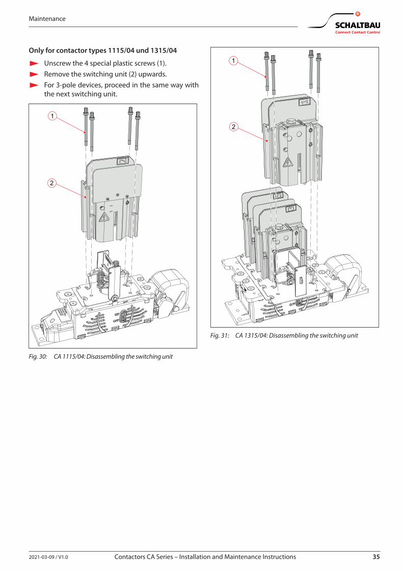
Only for contactor types 1115/04 und 1315/04
X Unscrew the 4 special plastic screws (1). X Remove the switching unit (2) upwards. X For 3-pole devices, proceed in the same way with
the next switching unit.
1
2
Fig. 30: CA 1115/04: Disassembling the switching unit
2
1
Fig. 31: CA 1315/04: Disassembling the switching unit
36 2021-03-09 / V1.0
Maintenance
Contactors CA Series – Installation and Maintenance Instructions
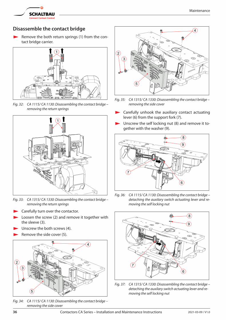
Disassemble the contact bridge X Remove the both return springs (1) from the con-
tact bridge carrier.
1
Fig. 32: CA 1115/ CA 1130: Disassembling the contact bridge – removing the return springs
1
Fig. 33: CA 1315/ CA 1330: Disassembling the contact bridge – removing the return springs
X Carefully turn over the contactor. X Loosen the screw (2) and remove it together with
the sleeve (3). X Unscrew the both screws (4). X Remove the side cover (5).
4
23
5
Fig. 34: CA 1115/ CA 1130: Disassembling the contact bridge – removing the side cover
4
23
5
Fig. 35: CA 1315/ CA 1330: Disassembling the contact bridge – removing the side cover
X Carefully unhook the auxiliary contact actuating lever (6) from the support fork (7).
X Unscrew the self locking nut (8) and remove it to-gether with the washer (9).
8
6
9
7
Fig. 36: CA 1115/ CA 1130: Disassembling the contact bridge – detaching the auxilary switch actuating lever and re-moving the self locking nut
8
6
9
7
Fig. 37: CA 1315/ CA 1330: Disassembling the contact bridge – detaching the auxilary switch actuating lever and re-moving the self locking nut
372021-03-09 / V1.0 Contactors CA Series – Installation and Maintenance Instructions
Maintenance
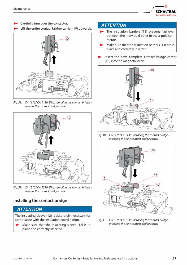
X Carefully turn over the contactor. X Lift the entire contact bridge carrier (10) upwards.
10
Fig. 38: CA 1115/ CA 1130: Disassembling the contact bridge – remove the contact bridge carrier
10
Fig. 39: CA 1315/ CA 1330: Disassembling the contact bridge – remove the contact bridge carrier
Installing the contact bridge
ATTENTIONThe insulating sleeve (12) is absolutely necessary for compliance with the insulation coordination.
X Make sure that the insulating sleeve (12) is in place and correctly inserted.
ATTENTION X The insulation barriers (13) prevent flashover
between the individual poles in the 3-pole con-tactors.
X Make sure that the insulation barriers (13) are in place and correctly inserted.
X Insert the new, complete contact bridge carrier (10) into the magnetic drive.
10
12
Fig. 40: CA 1115/ CA 1130: Installing the contact bridge – inserting the new contact bridge carrier
10
12
1313
Fig. 41: CA 1315/ CA 1330: Installing the contact bridge – inserting the new contact bridge carrier
38 2021-03-09 / V1.0
Maintenance
Contactors CA Series – Installation and Maintenance Instructions
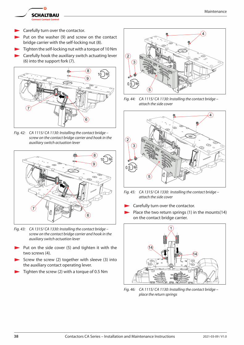
X Carefully turn over the contactor. X Put on the washer (9) and screw on the contact
bridge carrier with the self-locking nut (8). X Tighten the self-locking nut with a torque of 10 Nm X Carefully hook the auxiliary switch actuating lever
(6) into the support fork (7).
8
6
9
7
10 Nm
Fig. 42: CA 1115/ CA 1130: Installing the contact bridge – screw on the contact bridge carrier and hook in the auxiliary switch actuation lever
8
6
9
7
10 Nm
Fig. 43: CA 1315/ CA 1330: Installing the contact bridge – screw on the contact bridge carrier and hook in the auxiliary switch actuation lever
X Put on the side cover (5) and tighten it with the two screws (4).
X Screw the screw (2) together with sleeve (3) into the auxiliary contact operating lever.
X Tighten the screw (2) with a torque of 0.5 Nm
4
23
50.5 Nm
Fig. 44: CA 1115/ CA 1130: Installing the contact bridge – attach the side cover
4
23
5
0.5 Nm
Fig. 45: CA 1315/ CA 1330: Installing the contact bridge – attach the side cover
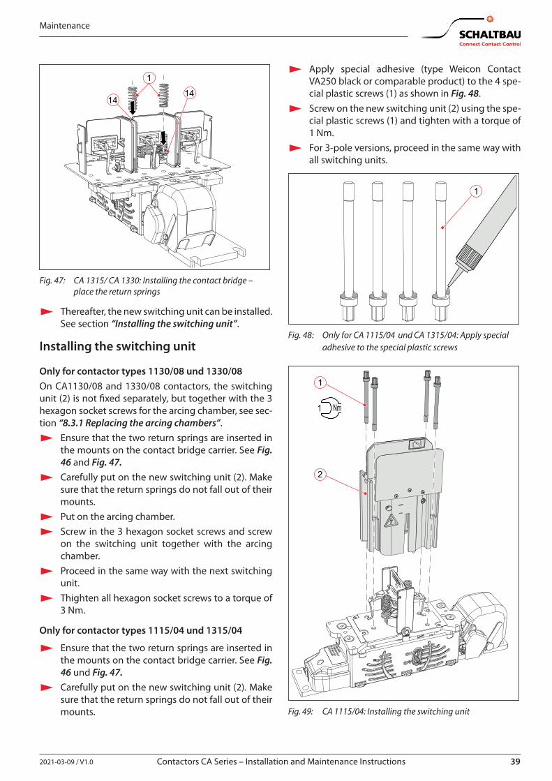
X Carefully turn over the contactor. X Place the two return springs (1) in the mounts(14)
on the contact bridge carrier.
1
1414
Fig. 46: CA 1115/ CA 1130: Installing the contact bridge – place the return springs
392021-03-09 / V1.0 Contactors CA Series – Installation and Maintenance Instructions
Maintenance
1
1414
Fig. 47: CA 1315/ CA 1330: Installing the contact bridge – place the return springs
X Thereafter, the new switching unit can be installed. See section “Installing the switching unit”.
Installing the switching unit
Only for contactor types 1130/08 und 1330/08On CA1130/08 and 1330/08 contactors, the switching unit (2) is not fixed separately, but together with the 3 hexagon socket screws for the arcing chamber, see sec-tion “8.3.1 Replacing the arcing chambers”.
X Ensure that the two return springs are inserted in the mounts on the contact bridge carrier. See Fig. 46 and Fig. 47.
X Carefully put on the new switching unit (2). Make sure that the return springs do not fall out of their mounts.
X Put on the arcing chamber. X Screw in the 3 hexagon socket screws and screw
on the switching unit together with the arcing chamber.
X Proceed in the same way with the next switching unit.
X Thighten all hexagon socket screws to a torque of 3 Nm.
Only for contactor types 1115/04 und 1315/04
X Ensure that the two return springs are inserted in the mounts on the contact bridge carrier. See Fig. 46 und Fig. 47.
X Carefully put on the new switching unit (2). Make sure that the return springs do not fall out of their mounts.
X Apply special adhesive (type Weicon Contact VA250 black or comparable product) to the 4 spe-cial plastic screws (1) as shown in Fig. 48.
X Screw on the new switching unit (2) using the spe-cial plastic screws (1) and tighten with a torque of 1 Nm.
X For 3-pole versions, proceed in the same way with all switching units.
1
Fig. 48: Only for CA 1115/04 und CA 1315/04: Apply special adhesive to the special plastic screws
1
2
1 Nm
Fig. 49: CA 1115/04: Installing the switching unit
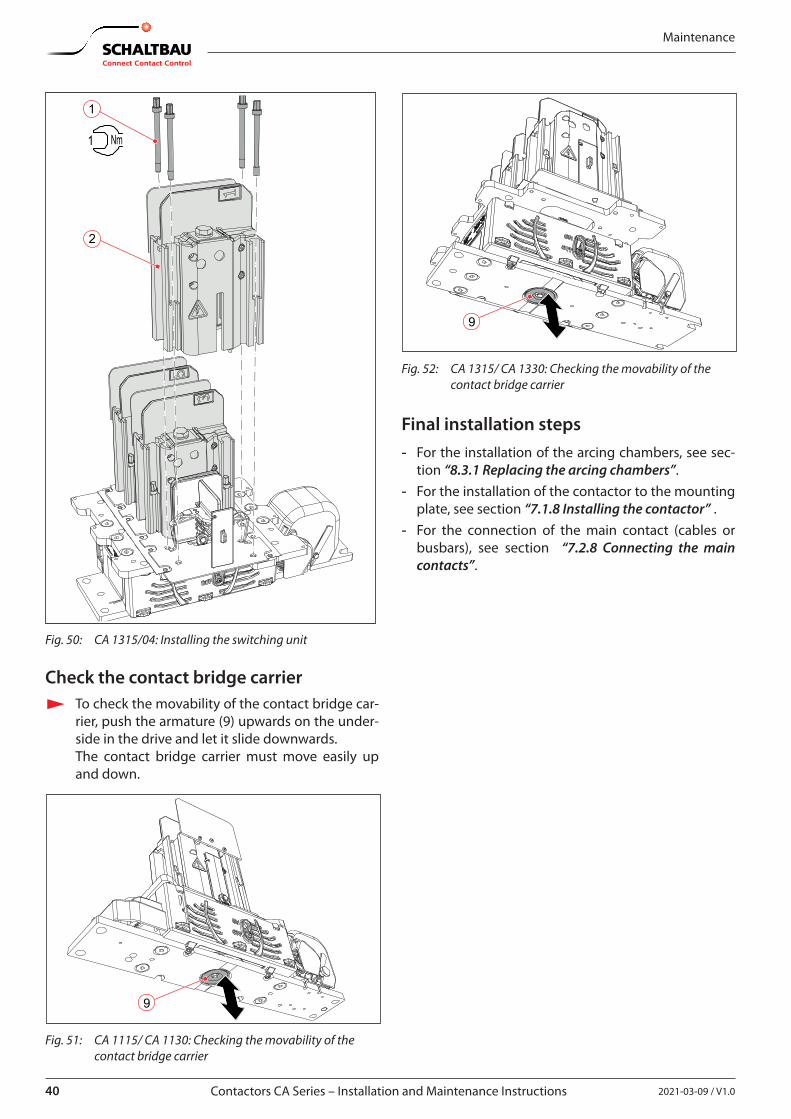
40 2021-03-09 / V1.0
Maintenance
Contactors CA Series – Installation and Maintenance Instructions
1
1 Nm
2
Fig. 50: CA 1315/04: Installing the switching unit
Check the contact bridge carrier X To check the movability of the contact bridge car-
rier, push the armature (9) upwards on the under-side in the drive and let it slide downwards.The contact bridge carrier must move easily up and down.
9
Fig. 51: CA 1115/ CA 1130: Checking the movability of the contact bridge carrier
9
Fig. 52: CA 1315/ CA 1330: Checking the movability of the contact bridge carrier
Final installation steps - For the installation of the arcing chambers, see sec-
tion “8.3.1 Replacing the arcing chambers”. - For the installation of the contactor to the mounting
plate, see section “7.1.8 Installing the contactor” . - For the connection of the main contact (cables or
busbars), see section “7.2.8 Connecting the main contacts”.
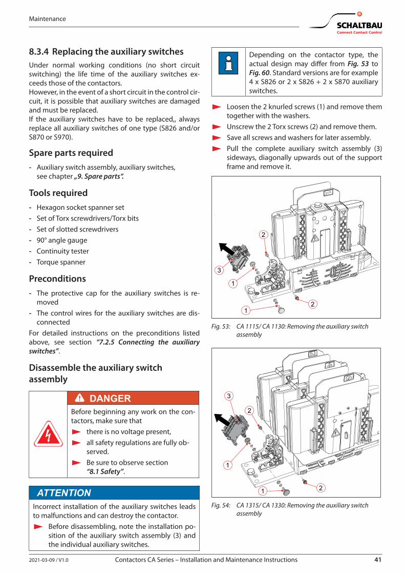
412021-03-09 / V1.0 Contactors CA Series – Installation and Maintenance Instructions
Maintenance
8.3.4 Replacing the auxiliary switchesUnder normal working conditions (no short circuit switching) the life time of the auxiliary switches ex-ceeds those of the contactors.However, in the event of a short circuit in the control cir-cuit, it is possible that auxiliary switches are damaged and must be replaced.If the auxiliary switches have to be replaced,, always replace all auxiliary switches of one type (S826 and/or S870 or S970).
Spare parts required - Auxiliary switch assembly, auxiliary switches,
see chapter „9. Spare parts“.
Tools required - Hexagon socket spanner set - Set of Torx screwdrivers/Torx bits - Set of slotted screwdrivers - 90° angle gauge - Continuity tester - Torque spanner
Preconditions - The protective cap for the auxiliary switches is re-
moved - The control wires for the auxiliary switches are dis-
connectedFor detailed instructions on the preconditions listed above, see section “7.2.5 Connecting the auxiliary switches”.
Disassemble the auxiliary switch assembly
DANGERBefore beginning any work on the con-tactors, make sure that
X there is no voltage present, X all safety regulations are fully ob-
served. X Be sure to observe section
“8.1 Safety”.
ATTENTIONIncorrect installation of the auxiliary switches leads to malfunctions and can destroy the contactor.
X Before disassembling, note the installation po-sition of the auxiliary switch assembly (3) and the individual auxiliary switches.
Depending on the contactor type, the actual design may differ from Fig. 53 to Fig. 60. Standard versions are for example 4 x S826 or 2 x S826 + 2 x S870 auxiliary switches.
X Loosen the 2 knurled screws (1) and remove them together with the washers.
X Unscrew the 2 Torx screws (2) and remove them. X Save all screws and washers for later assembly. X Pull the complete auxiliary switch assembly (3)
sideways, diagonally upwards out of the support frame and remove it.
21
1
2
3
Fig. 53: CA 1115/ CA 1130: Removing the auxiliary switch assembly
21
1
2
3
Fig. 54: CA 1315/ CA 1330: Removing the auxiliary switch assembly
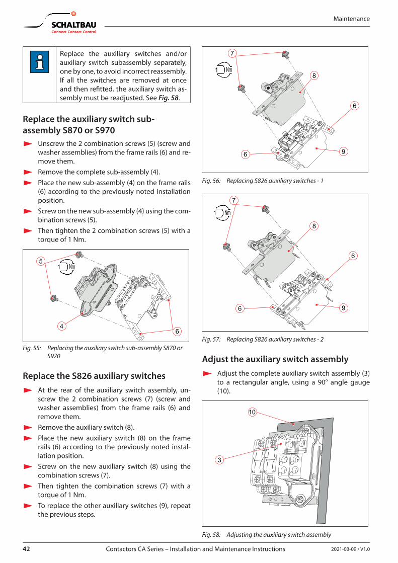
42 2021-03-09 / V1.0
Maintenance
Contactors CA Series – Installation and Maintenance Instructions
Replace the auxiliary switches and/or auxiliary switch subassembly separately, one by one, to avoid incorrect reassembly. If all the switches are removed at once and then refitted, the auxiliary switch as-sembly must be readjusted. See Fig. 58.
Replace the auxiliary switch sub-assembly S870 or S970
X Unscrew the 2 combination screws (5) (screw and washer assemblies) from the frame rails (6) and re-move them.
X Remove the complete sub-assembly (4). X Place the new sub-assembly (4) on the frame rails
(6) according to the previously noted installation position.
X Screw on the new sub-assembly (4) using the com-bination screws (5).
X Then tighten the 2 combination screws (5) with a torque of 1 Nm.
5
46
1 Nm
Fig. 55: Replacing the auxiliary switch sub-assembly S870 or S970
Replace the S826 auxiliary switches X At the rear of the auxiliary switch assembly, un-
screw the 2 combination screws (7) (screw and washer assemblies) from the frame rails (6) and remove them.
X Remove the auxiliary switch (8). X Place the new auxiliary switch (8) on the frame
rails (6) according to the previously noted instal-lation position.
X Screw on the new auxiliary switch (8) using the combination screws (7).
X Then tighten the combination screws (7) with a torque of 1 Nm.
X To replace the other auxiliary switches (9), repeat the previous steps.
7
6
6
8
9
1 Nm
Fig. 56: Replacing S826 auxiliary switches - 1
6
6
8
9
7
1 Nm
Fig. 57: Replacing S826 auxiliary switches - 2
Adjust the auxiliary switch assembly X Adjust the complete auxiliary switch assembly (3)
to a rectangular angle, using a 90° angle gauge (10).
3
10
Fig. 58: Adjusting the auxiliary switch assembly
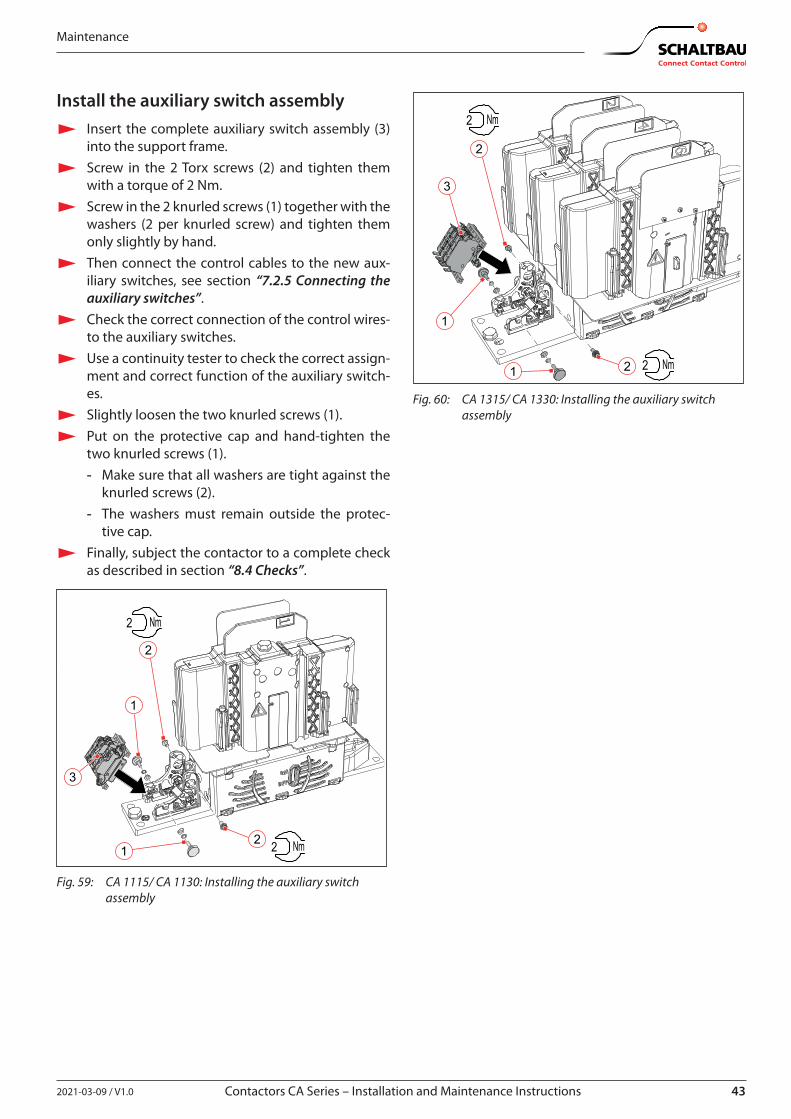
432021-03-09 / V1.0 Contactors CA Series – Installation and Maintenance Instructions
Maintenance
Install the auxiliary switch assembly X Insert the complete auxiliary switch assembly (3)
into the support frame. X Screw in the 2 Torx screws (2) and tighten them
with a torque of 2 Nm. X Screw in the 2 knurled screws (1) together with the
washers (2 per knurled screw) and tighten them only slightly by hand.
X Then connect the control cables to the new aux-iliary switches, see section “7.2.5 Connecting the auxiliary switches”.
X Check the correct connection of the control wires-to the auxiliary switches.
X Use a continuity tester to check the correct assign-ment and correct function of the auxiliary switch-es.
X Slightly loosen the two knurled screws (1). X Put on the protective cap and hand-tighten the
two knurled screws (1). - Make sure that all washers are tight against the
knurled screws (2). - The washers must remain outside the protec-
tive cap. X Finally, subject the contactor to a complete check
as described in section “8.4 Checks”.
21
1
2
3
2 Nm
2 Nm
Fig. 59: CA 1115/ CA 1130: Installing the auxiliary switch assembly
21
1
2
3
2 Nm
2 Nm
Fig. 60: CA 1315/ CA 1330: Installing the auxiliary switch assembly
44 2021-03-09 / V1.0
Maintenance
Contactors CA Series – Installation and Maintenance Instructions
8.4 ChecksAfter all installation and maintenance work, perform the following checks:
X Check that the contactors are correctly installed on the mounting plate/frame and tightly screwed in place.
X Check that the main circuit cables or busbars are correctly installed and fit tightly at the main con-tacts.
X Check correct connection and polarity of the con-trol wires at the coil terminals.
X Check that the control wires are correctly connect-ed to the auxiliary switches.Check the correct assignment and function of the auxiliary switches using a continuity tester.
X Check correct connection and tight fit of the earth-ing cable.
X Check that both protective caps (for auxiliary switches and coil connection) are in place and properly fastened.
X Check that all insulating panels are undamaged and firmly fixed.
X Switch the contactor several times without volt-age.
X Check the pull-in and drop-off voltage based on the Schaltbau specifications. See C28 catalogue.
X Check insulation voltage between earth, coil, main contacts and auxiliary switches.
X Check the routing of the wiring. Wires must not be squeezed or bent. If applicable bundle and secure wires using cable ties.
X After each installation and after maintenance work, check the contactor for correct operation according to the following standards: - EN/IEC 60077-2 - EN/IEC 60947-4-1
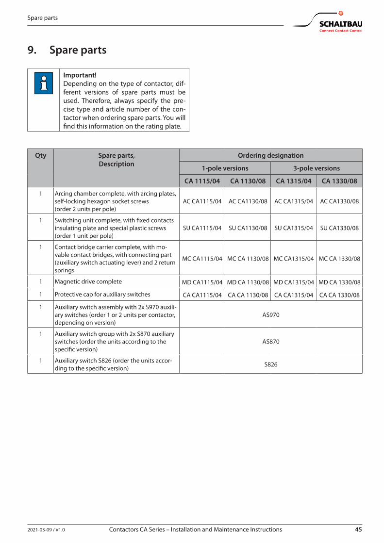
452021-03-09 / V1.0 Contactors CA Series – Installation and Maintenance Instructions
Spare parts
9. Spare parts
Important!Depending on the type of contactor, dif-ferent versions of spare parts must be used. Therefore, always specify the pre-cise type and article number of the con-tactor when ordering spare parts. You will find this information on the rating plate.
Qty Spare parts,Description
Ordering designation
1-pole versions 3-pole versions
CA 1115/04 CA 1130/08 CA 1315/04 CA 1330/08
1 Arcing chamber complete, with arcing plates, self-locking hexagon socket screws (order 2 units per pole)
AC CA1115/04 AC CA1130/08 AC CA1315/04 AC CA1330/08
1 Switching unit complete, with fixed contacts insulating plate and special plastic screws (order 1 unit per pole)
SU CA1115/04 SU CA1130/08 SU CA1315/04 SU CA1330/08
1 Contact bridge carrier complete, with mo-vable contact bridges, with connecting part (auxiliary switch actuating lever) and 2 return springs
MC CA1115/04 MC CA 1130/08 MC CA1315/04 MC CA 1330/08
1 Magnetic drive complete MD CA1115/04 MD CA 1130/08 MD CA1315/04 MD CA 1330/08
1 Protective cap for auxiliary switches CA CA1115/04 CA CA 1130/08 CA CA1315/04 CA CA 1330/08
1 Auxiliary switch assembly with 2x S970 auxili-ary switches (order 1 or 2 units per contactor, depending on version)
AS970
1 Auxiliary switch group with 2x S870 auxiliary switches (order the units according to the specific version)
AS870
1 Auxiliary switch S826 (order the units accor-ding to the specific version) S826
46 2021-03-09 / V1.0
Technical data
Contactors CA Series – Installation and Maintenance Instructions
10. Technical dataTechnical data and information on material properties for the CA series contactors can be found in our C28 catalogue.Schaltbau products are subject to continual improve-ment. Therefore, the product information in catalogues, data sheets, etc. may change at any time. Therefore, only the latest version of a catalogue is valid at any time – downloads available under:https://www.schaltbau.com/en/media-library/
11. DisposalThis product is designed for exclusive professional use by commercial companies. The owner is responsible for ensuring an environmentally sound disposal of this product at the end of its working life.This product or parts of it may not be disposed with other household wastes.To prevent possible harm to the environment or hu-man health from uncontrolled waste disposal, please separate this product or parts of it from other types of wastes and recycle it responsibly to promote the sus-tainable reuse of material resources.Please observe all local regulations and recommen-dations for the disposal, recycling or environmentally friendly processing of the parts and materials that have been used or replaced during installation, operation, and maintenance tasks.At the end of the product’s useful life ensure environ-mentally sound disposal of the product according to the legal regulations and requirements for electrical and electronic waste equipment in your country.
472021-03-09 / V1.0
Notes
Contactors CA Series – Installation and Maintenance Instructions
Notes
Schaltbau GmbHFor detailed information on our products and services visit our website – or give us a call!
Schaltbau GmbH Hollerithstrasse 5 81829 Munich Germany
Phone +49 89 9 30 05-0 Fax +49 89 9 30 05-350 Internet www.schaltbau.com e-Mail [email protected]
Connectors ■ Connectors manufactured to industry standards
■ Connectors to suit the special requirements of communications engineering (MIL connectors)
■ Charging connectors for battery-powered machines and systems
■ Connectors for railway engineering, including UIC connectors
■ Special connectors to suit customer requirements
Snap-action switches ■ Snap-action switches with positive opening operation
■ Snap-action switches with self-cleaning contacts
■ Snap-action switch made of robust polyetherimide (PEI)
■ Snap-action switch with two galvanically isolated contact bridges
■ Special switches to suit customer requirements
Contactors Emergency disconnect switches
■ Single and multi-pole DC contactors
■ High-voltage AC/DC contactors
■ Contactors for battery powered vehicles and power supplies
■ Contactors for railway applications
■ Terminal bolts and fuse holders
■ DC emergency disconnect switches
■ Special contactors to suit customer requirements
Electrics for rolling stock ■ Equipment for driver's cab
■ Equipment for passenger use
■ High-voltage switchgear
■ High-voltage heaters
■ High-voltage roof equipment
■ Equipment for electric brakes
■ Design and engineering of train electrics to customer requirements
with compliments:
The production facilities of Schaltbau GmbH have been IRIS
certified since 2008.
Certified to DIN EN ISO 14001 since 2002. For the most
recent certificate visit our website.
Certified to DIN EN ISO 9001 since 1994. For the most
recent certificate visit our website.
Electrical Components and Systems for Railway Engineering and Industrial Applications
Printed in Germany
We reserve the right to make technical alterations without prior notice.
For updated product information visit www.schaltbau-gmbh.com..
Related Documents