3. Artificial Lift System

Welcome message from author
This document is posted to help you gain knowledge. Please leave a comment to let me know what you think about it! Share it to your friends and learn new things together.
Transcript
3. Artificial Lift System
Introduction Why is Artificial Lift Needed?
• Well quit• Fluid Column no longer reaches the surface• Production declines with depletion of reservoir energy
• Water cut increases• Maximize production from naturally flowing wells
Note that this is different from gas injection for pressure maintenance• Injection of gas or water into reservoir to maintain reservoir pressure
• Improve recovery
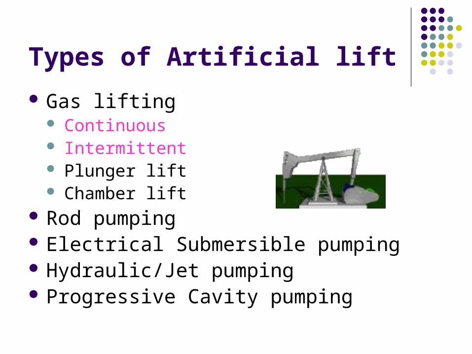
Types of Artificial lift Gas lifting
Continuous Intermittent Plunger lift Chamber lift
Rod pumping Electrical Submersible pumping Hydraulic/Jet pumping Progressive Cavity pumping
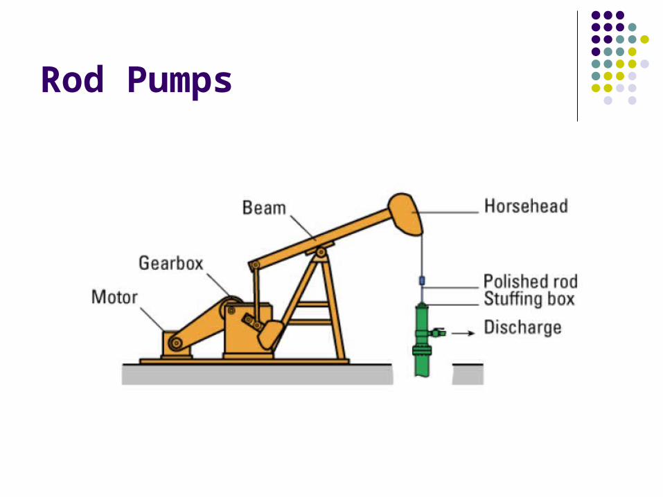
Rod Pumps
Beam Pumping/Sucker Rod Pumps (Rod Lift) This type of artificial lift utilizes a positive displacement pump that is inserted or set in the tubing near the bottom of the well. The pump plunger is connected to surface by a long rod string, called sucker rods, and operated by a beam unit at surface. Each upstroke of the beam unit lifts the oil above the pump’s plunger
Beam Pumping/Sucker Rod Pumps Advantages High system efficiency Optimization controls available Economical to repair and service Positive displacement/strong drawdown Upgraded materials can reduce corrosion concerns
Flexibility -- adjust production through stroke length and speed
High salvage value for surface unit and downhole equipment
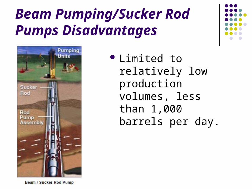
Beam Pumping/Sucker Rod Pumps Disadvantages
Limited to relatively low production volumes, less than 1,000 barrels per day.
Progressing Cavity Pumps (PCP Pumps)
Progressing Cavity Pumping (PCP) Systems consist of :- surface drive- drive string - downhole PC pump. The PC pump is comprised of a single helical-shaped rotor that turns inside a double helical elastomer-lined stator. The stator is attached to the production tubing string and remains stationary during pumping.
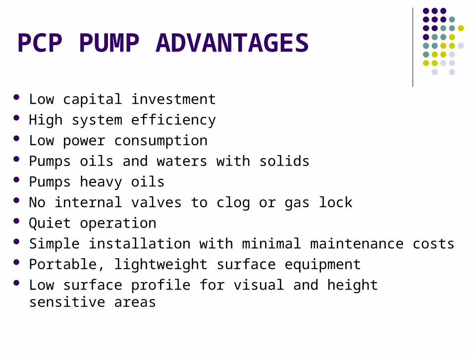
PCP PUMP ADVANTAGES Low capital investment High system efficiency Low power consumption Pumps oils and waters with solids Pumps heavy oils No internal valves to clog or gas lock Quiet operation Simple installation with minimal maintenance costs Portable, lightweight surface equipment Low surface profile for visual and height sensitive areas
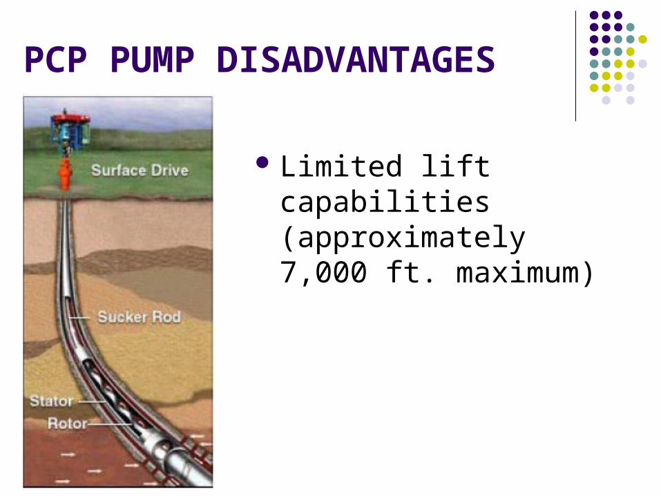
PCP PUMP DISADVANTAGES
Limited lift capabilities (approximately 7,000 ft. maximum)
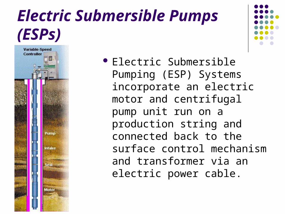
Electric Submersible Pumps (ESPs)
Electric Submersible Pumping (ESP) Systems incorporate an electric motor and centrifugal pump unit run on a production string and connected back to the surface control mechanism and transformer via an electric power cable.
ESP ADVANTAGES High volume and depth capacity High efficiency over 1,000 BPD Low maintenance Minimal surface equipment requirements High resistance to corrosive downhole environments
Use in deviated wells and vertical wells with doglegs
Adaptable to wells with 4 1/2" casing or largerESP DISADVANTAGES
Poor ability to pump sand
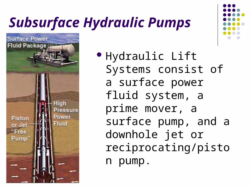
Subsurface Hydraulic Pumps
Hydraulic Lift Systems consist of a surface power fluid system, a prime mover, a surface pump, and a downhole jet or reciprocating/piston pump.
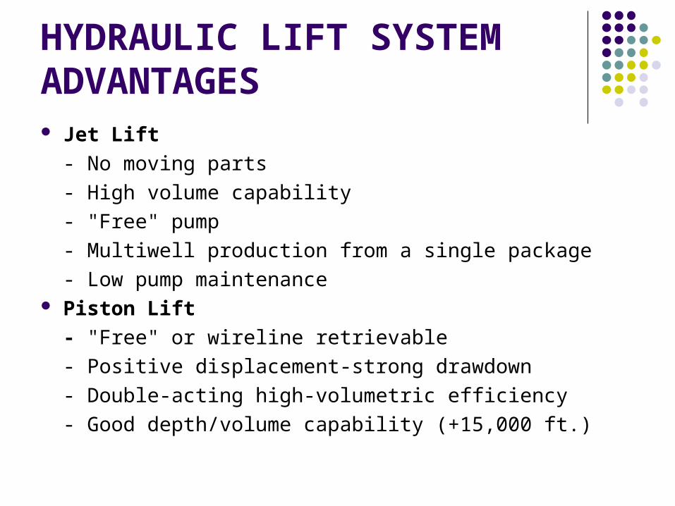
HYDRAULIC LIFT SYSTEM ADVANTAGES Jet Lift- No moving parts- High volume capability- "Free" pump- Multiwell production from a single package- Low pump maintenance
Piston Lift- "Free" or wireline retrievable- Positive displacement-strong drawdown- Double-acting high-volumetric efficiency- Good depth/volume capability (+15,000 ft.)
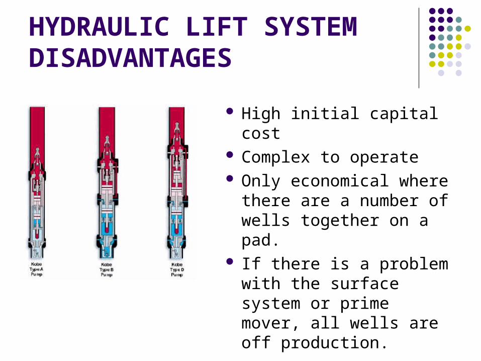
HYDRAULIC LIFT SYSTEM DISADVANTAGES
High initial capital cost
Complex to operate Only economical where there are a number of wells together on a pad.
If there is a problem with the surface system or prime mover, all wells are off production.
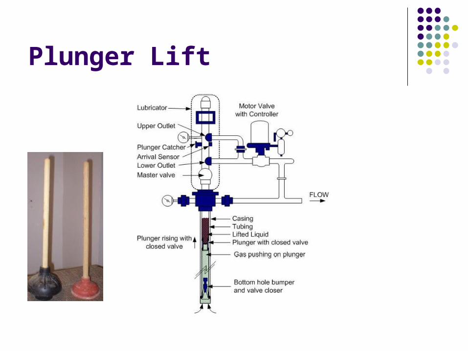
Plunger Lift
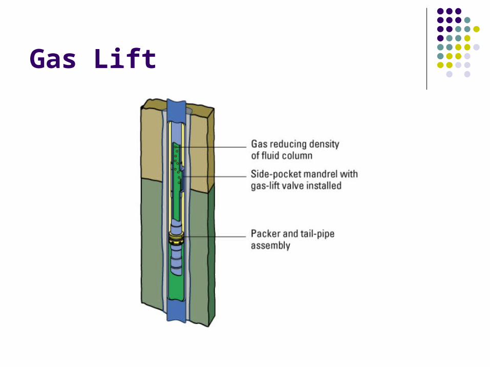
Gas Lift
Gas lift Principles The injected gas aerates the fluid column and reduce the density of the fluid
As the gas moves up the tubing, it expands providing the scrubbing action to bring the fluid column to surface
With the density of the column reduced, less reservoir pressure is required to push the liquid to surface.
In other words the hydrostatic back pressure to the reservoir is reduced and the reservoir pressure can overcome this reduced pressure and initiates the well to flow.
To recap we use gas lift … To enable the well that will not flow naturally to produce
To increase production rates in natural flowing wells
To kick off wells that will later flow naturally
To remove or unload fluids from gas wells.
Advantages of Gas lift Initial down hole equipment costs lower Low operational and maintenance cost Simplified well completions Can best handle sand / gas / deviated wells
Flexibility, can handle high rates and high gas oil ratio wells
Intervention relatively less expensive Can be use offshore, small foot print needed at the well head
Electrical power not needed at well head
Disadvantages of Gas lift Must have a source of gas Imported gas from other fields may result in start up problems
Possible high installation cost Top sides modifications to existing platforms Compressor installation Limited by available reservoir pressure and bottom hole flowing pressure
Significant effort required to operate effectively
Quite inefficient Much of the industry expertise has been (is been) lost
Gas lifting Method - Continuous Continuous flow is similar to natural flow and is achieved
by controlling the injection of gas into the fluid column to cause aeration from the point of injection
Advantages: Take full advantage of the gas energy available in the
reservoir. Higher production volume Equipment can be centralized Valves can either be wireline or tubing retrieved
Disadvantages: Must have a continuous source of gas. Rates to be above 150 bpd for efficient lifting. Bottom hole producing pressure increases both with depths
and volume
Gas lifting Method - Intermittent
Intermittent flow is by injecting gas of sufficient volume and pressure into tubing beneath a fluid column to lift liquid to the surface, this usually require high gas rate to reduce the liquid fallback. The liquid to surface is in slug or piston form.
Advantages: Can obtain lower producing bottom hole pressure than continuous
flow and at low rates. Suitable for well with production below 150 bpd (low P.I wells) Can remedy wax deposition in tubing for waxy crud
Disadvantages: Limited in volume. Causes surge on surface equipment. Equipment must be design to handle the surge. Cause interruption to other flowing wells in the production
system Possible sand production for unconsolidated sands
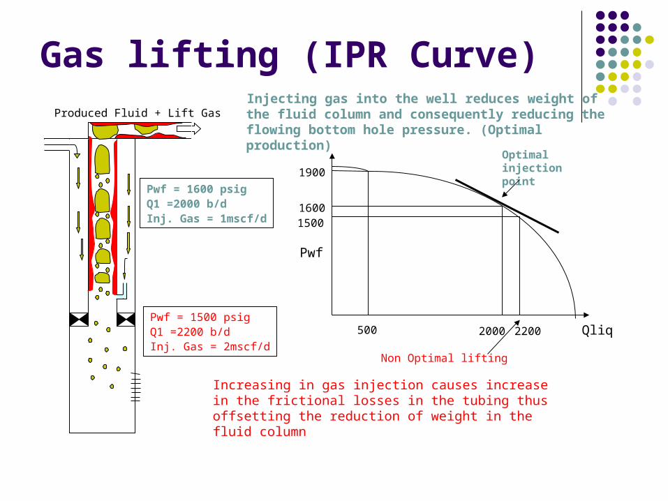
Injecting gas into the well reduces weight of the fluid column and consequently reducing the flowing bottom hole pressure. (Optimal production)
Increasing in gas injection causes increase in the frictional losses in the tubing thus offsetting the reduction of weight in the fluid column
Pwf
Qliq500
1900
1600
2000 2200
Optimal injection point
Non Optimal lifting
1500
Pwf = 1600 psigQ1 =2000 b/dInj. Gas = 1mscf/d
Pwf = 1500 psigQ1 =2200 b/dInj. Gas = 2mscf/d
Produced Fluid + Lift Gas
Gas lifting (IPR Curve)
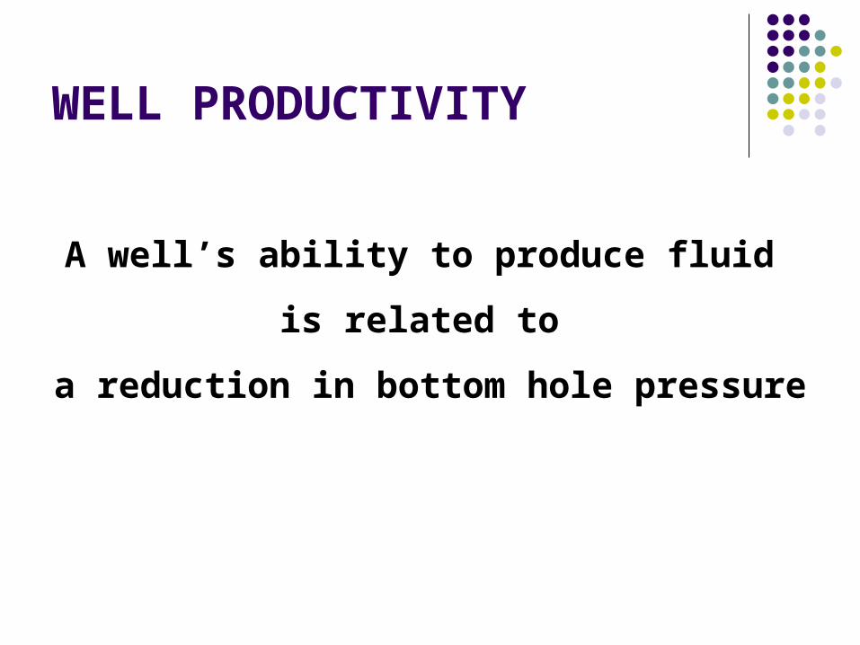
A well’s ability to produce fluid is related to
a reduction in bottom hole pressure
WELL PRODUCTIVITY
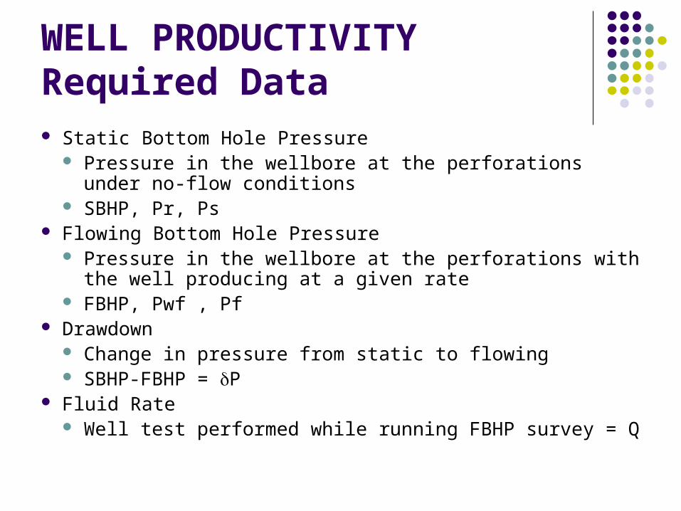
WELL PRODUCTIVITYRequired Data Static Bottom Hole Pressure
Pressure in the wellbore at the perforations under no-flow conditions
SBHP, Pr, Ps Flowing Bottom Hole Pressure
Pressure in the wellbore at the perforations with the well producing at a given rate
FBHP, Pwf , Pf Drawdown
Change in pressure from static to flowing SBHP-FBHP = P
Fluid Rate Well test performed while running FBHP survey = Q
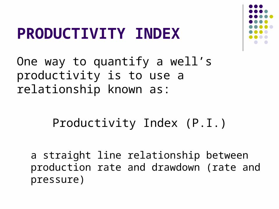
PRODUCTIVITY INDEXOne way to quantify a well’s productivity is to use a relationship known as:
Productivity Index (P.I.)
a straight line relationship between production rate and drawdown (rate and pressure)
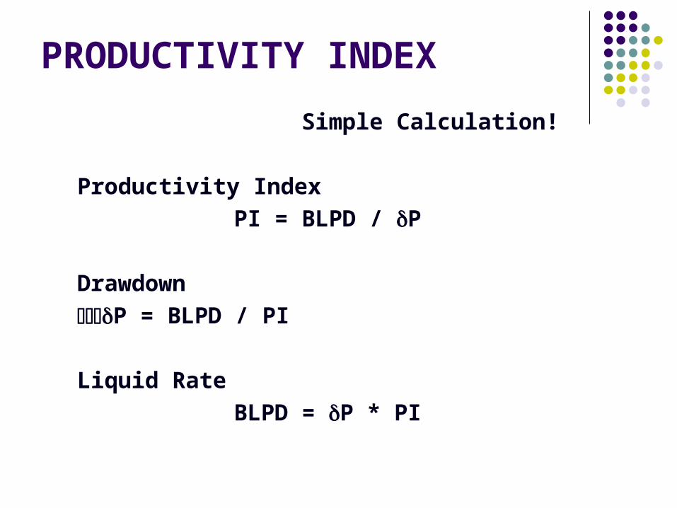
Simple Calculation!
Productivity IndexPI = BLPD / P
DrawdownP = BLPD / PI
Liquid RateBLPD = P * PI
PRODUCTIVITY INDEX
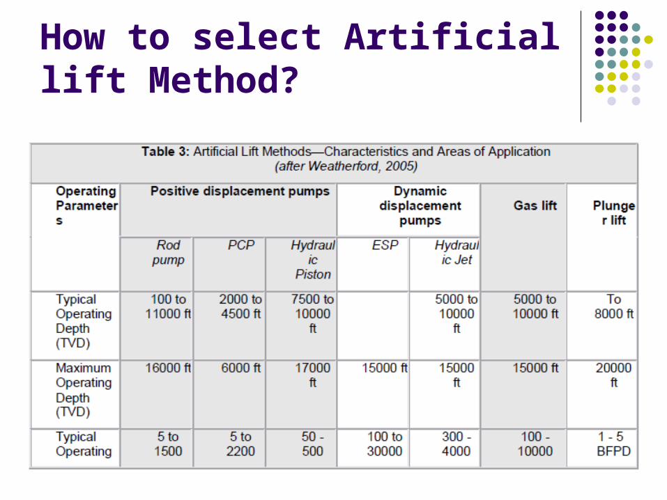
How to select Artificial lift Method?
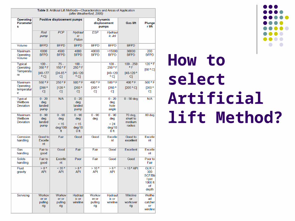
How to select Artificial lift Method?
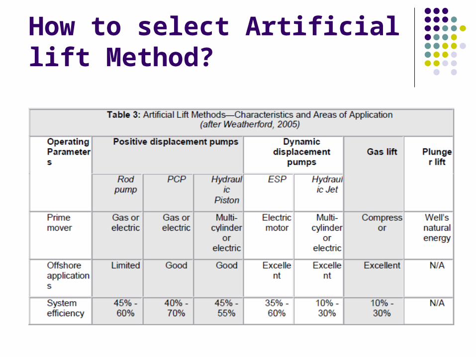
How to select Artificial lift Method?
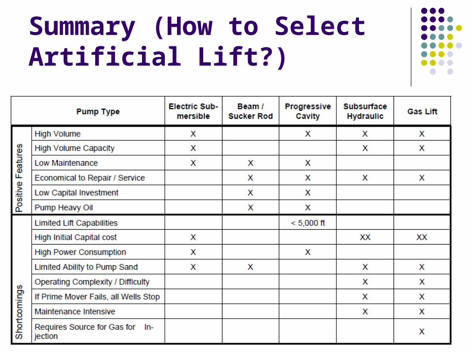
Summary (How to Select Artificial Lift?)
Economics of Artificial Lift
The features, benefits and limitations of one artificial lift method are relative to those of the other methods under consideration. Each method should be evaluated from the standpoint of comparative economics. Brown (1980) lists six critical bases of comparison:
Initial capital cost Monthly operating expense Equipment life Number of wells to be lifted Surplus equipment availability Expected producing life of well(s)
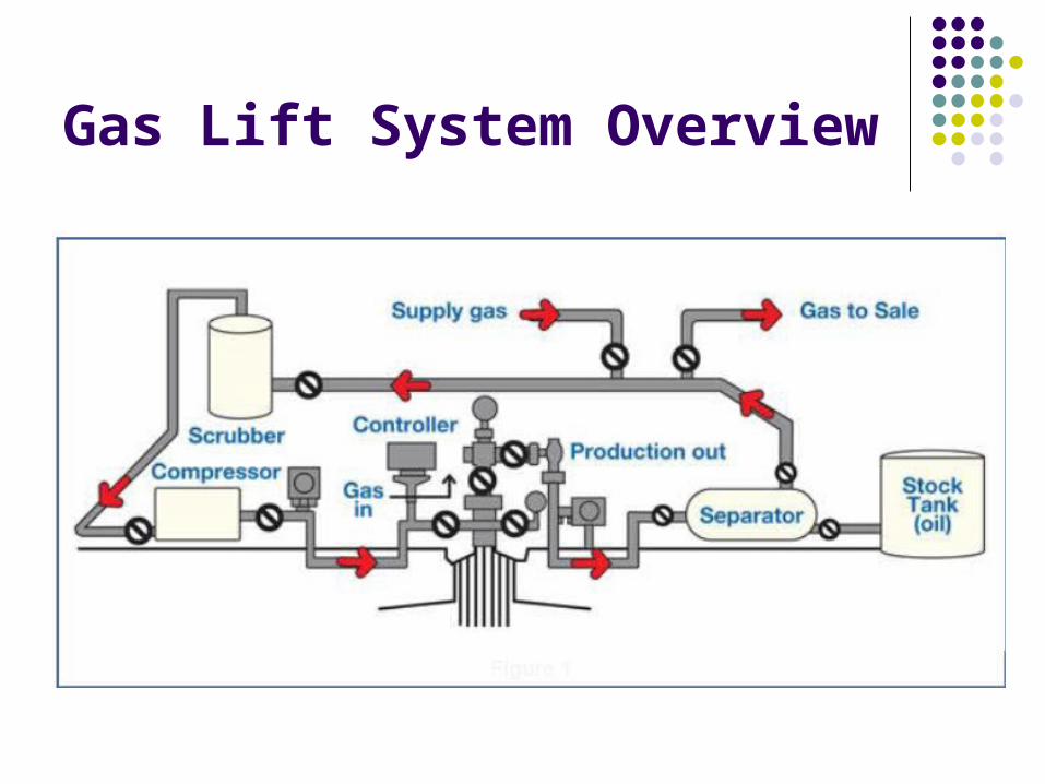
Gas Lift System Overview
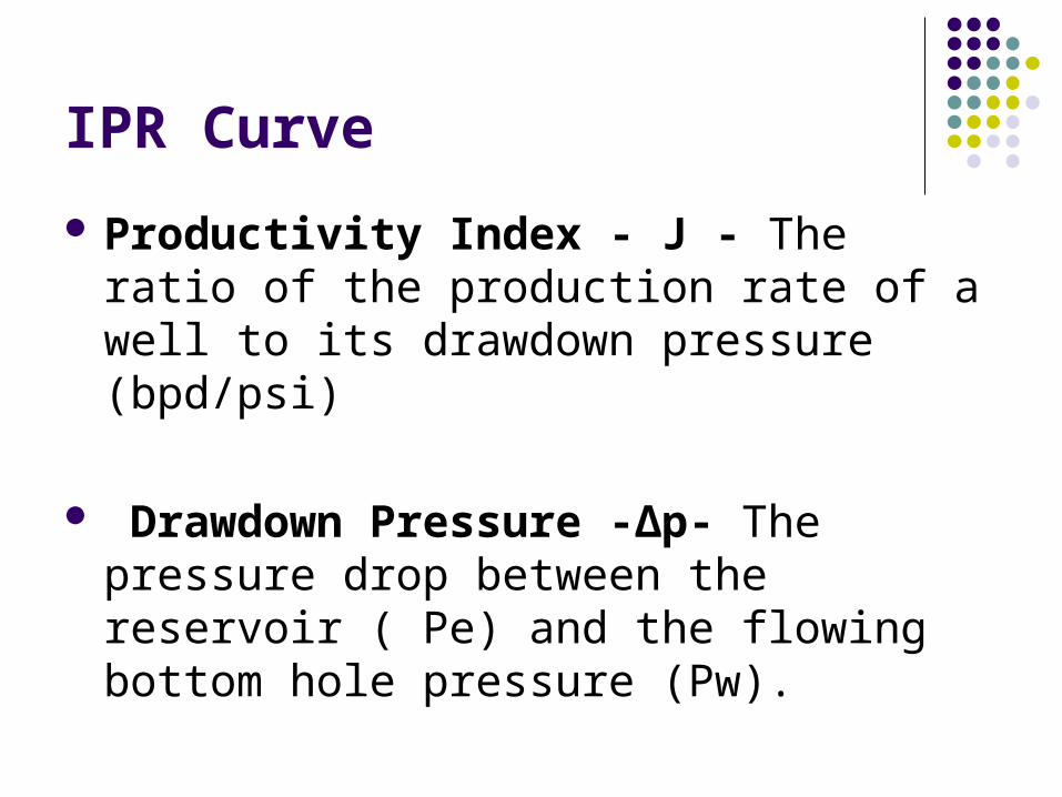
IPR Curve Productivity Index - J - The ratio of the production rate of a well to its drawdown pressure (bpd/psi)
Drawdown Pressure -Δp- The pressure drop between the reservoir ( Pe) and the flowing bottom hole pressure (Pw).
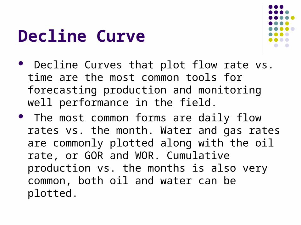
Decline Curve Decline Curves that plot flow rate vs. time are the most common tools for forecasting production and monitoring well performance in the field.
The most common forms are daily flow rates vs. the month. Water and gas rates are commonly plotted along with the oil rate, or GOR and WOR. Cumulative production vs. the months is also very common, both oil and water can be plotted.
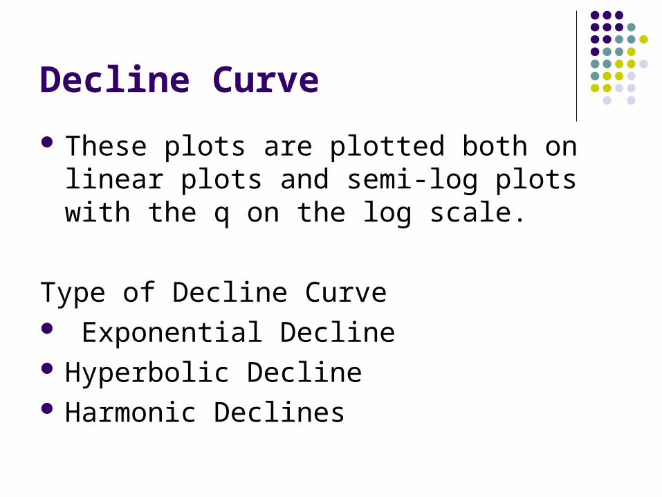
Decline Curve These plots are plotted both on linear plots and semi-log plots with the q on the log scale.
Type of Decline Curve Exponential Decline Hyperbolic Decline Harmonic Declines
Productivity Index
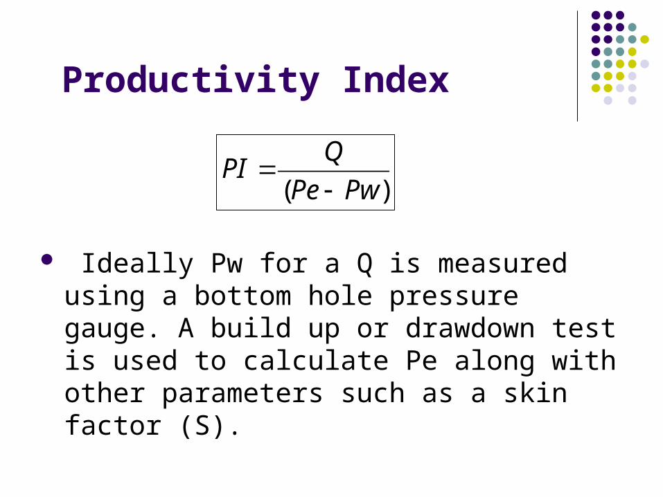
Ideally Pw for a Q is measured using a bottom hole pressure gauge. A build up or drawdown test is used to calculate Pe along with other parameters such as a skin factor (S).
)( PwPeQPI
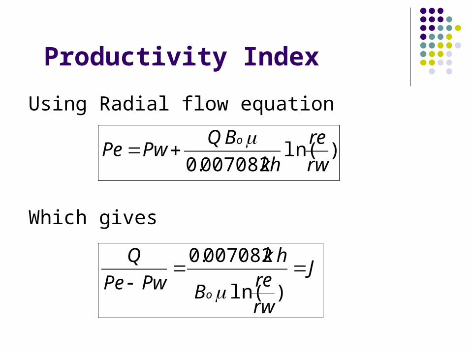
Productivity IndexUsing Radial flow equation
Which gives
)ln(007082.0 rwre
hkBQPwPe o
J
rwreB
hkPwPe
Q
o
)ln(
007082.0

END
Related Documents