THDC INDIA LIMITED (A Joint Venture of Govt. of India & Govt. of U.P.) 2X660 MW KHURJA STPP TECHNICAL SPECIFICATION FOR ELEVATOR SPECIFICATION NO.: PE-TS-475-502-A001 BHARAT HEAVY ELECTRICALS LIMITED (A Govt. of India Undertaking) POWER SECTOR PROJECT ENGINEERING MANAGEMENT NOIDA, U.P INDIA 1 288648/2021/PS-PEM-MAX 3

Welcome message from author
This document is posted to help you gain knowledge. Please leave a comment to let me know what you think about it! Share it to your friends and learn new things together.
Transcript

THDC INDIA LIMITED (A Joint Venture of Govt. of India & Govt. of U.P.)
2X660 MW KHURJA STPP
TECHNICAL SPECIFICATION FOR
ELEVATOR
SPECIFICATION NO.: PE-TS-475-502-A001
BHARAT HEAVY ELECTRICALS LIMITED(A Govt. of India Undertaking)
POWER SECTORPROJECT ENGINEERING MANAGEMENT
NOIDA, U.PINDIA
1
288648/2021/PS-PEM-MAX3

2X660 MW KHURJA STPP
ELEVATOR
INDEX
SPECIFICATION No: PE-TS-475-502-A001 SECTION REV. 00 APR 2021 SHEET : 1 OF 1
INDEX
SECTIONS
TITLE Page No.
I SPECIFIC TECHNICAL REQUIREMENT 4
IA
SPECIFIC TECHNICAL REQUIREMENT (MECHANICAL) 5
INTENT OF SPECIFICATIONS/ SCOPE OF ENQUIRY 6-8
SCOPE OF SUPPLY & SERVICES 9-18
CUSTOMER SPECIFICATON FOR ELEVATOR 19-25
GENERAL TECHNICAL REQUIREMENT 26-125
FUNCTIONAL / PERFORMANCE / DEMONSTRATION GUARANTEE (AS APPLICABLE)
126-127
QUALITY ASSURANCE 128-132
PAINTING SPECIFICATION 133-138
ANNEXURE-I- LIST OF MAKES 139-141
ANNEXURE-II- MANDATORY SPARE LIST 142-144
ANNEXURE-III- LIST OF TOOLS & TACKLES 145-146
ANNEXURE-IV- DRAWING / DOCUMENT SUBMISSION SCHEDULE 147
ANNEXURE-V- MAIN DRAWING LIST WITH SCHEDULE OF SUBMISSION
148
ANNEXURE-VI- FORMAT FOR OPERATION AND MAINTENANCE MANUAL
149-151
ANNEXURE-VII- SITE STORAGE AND PRESERVATION. 152-166
ANNEXURE-VIII- PACKING PROCEDURE 167-183 ANNEXURE-IX- CIVIL INPUT 184-186
IB
SPECIFIC TECHNICAL REQUIREMENT (ELECTRICAL) 187-188 ELECTRICAL SCOPE BETWEEN BHEL AND VENDOR 189 MOTOR DATASHEET A 190-191 MOTOR DATASHEET C 192-193 CUSTOMER SPECIFICATION FOR ELECTRICAL PART
� ELEVATOR-(ELECTRICALS) � MOTORS � LT POWER CABLES � LT CONTROL CABLES � CABLING EARTHING LIGHTNING AND PROTECTION � LT SWITCHGEAR & LT BUSDUCT
194 195-197 198-207 208-214 215-221 222-246 247-256
STANDARD MANUFACTURING QUALITY PLAN FOR MOTORS (UPTO 55 KW)
257-259
CABLE SCHEDULE FORMAT 260
IC DATA SHEET-A 261-264
2
288648/2021/PS-PEM-MAX4

2X660 MW KHURJA STPP
ELEVATOR
INDEX
SPECIFICATION No: PE-TS-475-502-A001 SECTION REV. 00 APR 2021 SHEET : 2 OF 1
II STANDARD TECHNICAL SPECIFICATION REQUIREMENT 265-270 IIA STANDARD TECHNICAL SPECIFICATION REQUIREMENT
(ELECTRICAL) � TECHNICAL SPECIFICATION FOR VVVF DRIVE FOR
ELEVATOR III LIST OF DOCUMENTS TO BE SUBMITTED WITH BID 272
PRE BID CLARIFICATION SCHEDULE 273 COMPLIANCE CUM CONFIRMATION CERTIFICATE 274-275 ELECTRICAL LOAD LIST 276
3
288648/2021/PS-PEM-MAX5
2X660 MW KHURJA STPP
TECHNICAL SPECIFICATION FOR ELEVATOR
SPECIFIC TECHNICAL REQUIREMENT
SPECIFICATION No: PE-TS-475-502-A001 SECTION I REV. 00 APR 2021
SECTION - I
SPECIFIC TECHNICAL REQUIREMENT
4
288648/2021/PS-PEM-MAX6
2X660 MW KHURJA STPP
TECHNICAL SPECIFICATION FOR ELEVATOR
SPECIFIC TECHNICAL REQUIREMENT -MECHANICAL
SPECIFICATION No: PE-TS-475-502-A001 VOL IIB SECTION IA REV. 00 APR 2021
SECTION – IA
SPECIFIC TECHNICAL REQUIREMENT-MECHANICAL
5
288648/2021/PS-PEM-MAX7

2X660 MW KHURJA STPP
TECHNICAL SPECIFICATION FOR ELEVATOR
SPECIFIC TECHNICAL REQUIREMENT
SPECIFICATION No: PE-TS-475-502-A001 VOL IIB SECTION IA REV. 00 APR 2021
SCOPE OF ENQUIRY /
INTENT OF SPECIFICATION
6
288648/2021/PS-PEM-MAX8

2X660 MW KHURJA STPP
TECHNICAL SPECIFICATION FOR ELEVATOR
SPECIFIC TECHNICAL REQUIREMENT
SPECIFICATION No: PE-TS-475-502-A001 VOL IIB SECTION IA REV. 00 APR 2021
SCOPE OF ENQUIRY / INTENT OF SPECIFICATION 1.1 This specification includes, but not limited to design, engineering, material selection,
manufacturing and assembly, inspection, testing at manufacturer's works, packing, forwarding and transportation to site, unloading, storage & handling at site, erection & commissioning, carrying out trial run and acceptance / functional guarantee test at site & final painting of passenger elevator for 2X660 MW KHURJA STPP, U.P STATE and necessary accessories including supply of mandatory spares, erection and commissioning spares, special maintenance tools and tackles etc.
1.2 The contractor shall be responsible for providing all material, equipment & services, which are
required to fulfil the intent of ensuring operability, maintainability, reliability and complete safety of the complete work covered under this specification, irrespective of whether it has been specifically listed herein or not. Omission of specific reference to any component / accessory necessary for proper performance of the equipment shall not relieve the responsibility of providing such facilities to complete the supply, erection and commissioning of the Elevators and its accessories.
1.3 It is not the intent to specify herein all the details of design and manufacture. However, the
equipment shall conform in all respects to high standards of design, engineering and workmanship and shall be capable of performing the required duties in a manner acceptable to purchaser who will interpret the meaning of drawings and specifications and shall be entitled to reject any work or material which in his judgement is not in full accordance herewith.
1.4 The extent of supply under the contract includes all items shown in the drawings,
notwithstanding the fact that such items may have been omitted from the specification or schedules. Similarly, the extent of supply also includes all items mentioned in the specification and /or schedules, notwithstanding the fact that such items may have been omitted in the drawing.
1.5 The general term and conditions, instructions to tenderer and other attachment referred to
elsewhere are made part of the tender specification. The equipment materials and works covered by this specification is subject to compliance to all attachments referred to in the specification. The bidder shall be responsible for and governed by all requirements stipulated herein.
1.6 While all efforts have been made to make the specification requirement complete &
unambiguous, it shall be bidders’ responsibility to ask for missing information, ensure completeness of specification, to bring out any contradictory / conflicting requirement in different sections of the specification and within a section itself to the notice of BHEL and to seek any clarification on specification requirement in the format enclosed under Vol-III of the specification. In absence of any such clarifications, in case of any contradictory requirement, the more stringent requirement as per interpretation of Purchaser/Customer shall prevail and shall be complied by the bidder without any commercial implication on account of the same. Further in case of any missing information in the specification not brought out by the prospective bidders as part of pre-bid clarification, the same shall be furnished by Purchaser/ Customer as and when brought to their notice either by the bidder or by purchaser/ customer themselves. However, such requirements shall be binding on the successful bidder without any commercial & delivery implication.
1.7 The bidder’s offer shall not carry any sections like clarification, interpretations and /or
assumptions. 1.8 Deviations, if any, should be very clearly brought out clause by clause in the enclosed
schedule; otherwise, it will be presumed that the vendor's offer is strictly in line with NIT specification.
7
288648/2021/PS-PEM-MAX9

2X660 MW KHURJA STPP
TECHNICAL SPECIFICATION FOR ELEVATOR
SPECIFIC TECHNICAL REQUIREMENT
SPECIFICATION No: PE-TS-475-502-A001 VOL IIB SECTION IA REV. 00 APR 2021
1.9 In case all above requirements are not complied with, the offer may be considered as
incomplete and would become liable for rejection. 1.10 Unless specified otherwise, all through the specification, the word contractor shall have same
meaning as successful bidder /vendor and Customer/ Purchaser/Employer will mean BHEL and /or customer including their consultant as interpreted by BHEL in the relevant context.
1.11 The standard quality plan is included in this specification to enable the bidder to understand
the extent of inspection and testing requirements to execute this job. The successful bidder
has to follow the quality plan as minimum requirement during manufacturing and testing.
1.12 Site Visit before submission of offer.
Bidders shall make Site visit in order to familiarize themselves with existing condition of site before submitting the bid in order to make their offer complete. During detail engineering also, the successful bidder shall be responsible for the correctness of details wrt existing facility at site. Customer approval on any drawing having details of existing facility shall not be cited by the successful bidder a valid reason for any shortcoming in the work by them. BHEL shall also not entertain any cost implication for any lack of input data with regard to site during detail engineering.
1.13 Compliance cum confirmation certificate is to be accepted by bidder without any modification.
1.14 Other requirements
Successful bidder shall furnish detailed erection manual for each of the equipment supplied under this contract at least 3 months before the scheduled erection of the concerned equipment / component or along with supply of concerned equipment / component whichever is earlier. Document approval by customer under Approval category or information category shall not absolve the vendor of their contractual obligations of completing the work as per specification requirement. Any deviation from specified requirement shall be reported by the vendor in writing and require written approval. Unless any change in specified requirement has been brought out by the vendor during detail engineering in writing while submitting the document to customer for approval, approved document (with implicit deviation) will not be cited as a reason for not following the specification requirement. In case vendor submits revised drawing after approval of the corresponding drawing, any delay in approval of revised drawing shall be to vendor’s account and shall not be used as a reason for extension in contract completion.
8
288648/2021/PS-PEM-MAX10

2X660 MW KHURJA STPP
TECHNICAL SPECIFICATION FOR ELEVATOR
SPECIFIC TECHNICAL REQUIREMENT -MECHANICAL
SPECIFICATION No: PE-TS-475-502-A001 SECTION IA REV. 00 APR 2021
SCOPE OF SUPPLY & SERVICES, EXCLUSION AND
TERMINAL POINTS.
9
288648/2021/PS-PEM-MAX11

2X660 MW KHURJA STPP
TECHNICAL SPECIFICATION FOR ELEVATOR
SPECIFIC TECHNICAL REQUIREMENT -MECHANICAL
SPECIFICATION No: PE-TS-475-502-A001 SECTION IA REV. 00 APR 2021
1.0 Introduction Passenger elevator shall be provided for access to various operating floors / platforms in TG
building and Service building for 2X660 MW KHURJA STPP to facilitate movement of operating and maintenance personnel.
2.0 Scope of equipment supply and services 2.0.1 Design, Engineering, Manufacture, Inspection & Testing at manufacturer's works or at their
sub-vendor's works, Painting at manufacturer's or at their sub-vendor's works, duly packed for transportation to site, delivery to site, storage and handling at site, Erection & Commissioning, carrying out trial run and Acceptance / functional tests at site & final painting of Passenger Elevators for 2 X 660 MW khurja STPP as listed below: -
Sl. no
Building No. of elevators
Capacity No. of landings Total rise
Type Speed
1 TG building 1 No. 884 Kg Four including Ground. (0.0 m, 8.5 m, 17.0 m, and last landing at 25.5 m,
25.5 M Conventional (passenger elevator)
1 M/s
2 Service Building
2 Nos. 884 Kg Five including Ground. (0.0 m, 4.5 m, 9 m, 13.5 m, and last landing at 18 m,
18 M Conventional (passenger elevator)
1 M/s
2.0.2 Elevator shall include but shall not be limited to the following: - 1) Elevator car with SS 304, 1.5 mm (min) thick sheet of hair line finish for TG and Service
building. 2) Guide rails for car and counterweights. 3) Counterweight. 4) DCEM brakes. 5) Spring buffer for car and counterweight. 6) Driving arrangement including motor, gear box, sheaves etc. 7) All electrical equipment including power cable, control cable, controller panel, safety devices
including push buttons, limit switches, safety switches, indicators etc. 8) Isolating switch / MCBs. 9) Car doors, car ceiling and hoist way doors of SS 304, 1.5 MM (min) thick sheet of hair line
finish. 10) Car operating panel, digital control, car position indicator at all floors, luminous hall buttons,
auto door operating mechanism, alarm bell, car light & car fan. 11) Intercom connection through EPABX or PA which shall be finalized during contract stage.
10
288648/2021/PS-PEM-MAX12

2X660 MW KHURJA STPP
TECHNICAL SPECIFICATION FOR ELEVATOR
SPECIFIC TECHNICAL REQUIREMENT -MECHANICAL
SPECIFICATION No: PE-TS-475-502-A001 SECTION IA REV. 00 APR 2021
12) Ropes for hoisting. 13) Circuit breaker, switch fuse unit etc. in machine room for terminating the power supply cable
(power supply cable provided by purchaser up to machine room level), other power/control and trailing cabling and equipment earthling.
14) Ladder in pits. 15) Emergency light with rechargeable battery. 16) All fixing materials require fixing rails, brackets, equipment including nuts and bolts. 17) Fascia plates (750 mm minimum) & sill angels. 18) Full length infra-red Curtain safety feature in door along with pressure limiter as an extra
mechanical safety. 19) ELCB if required as per statutory requirement. 20) Any other equipment required to meet the requirement of local statuary and regulatory body
and prevailing lift etc. 21) Car lighting, LED light fittings for illumination level of 100 lux on car floor. 22) Elevator shaft, pit cable conduit fixtures, switches 3 pin or as required by bidder during
erection / maintenance purpose at every 3 m. 23) Mirror for the car rear panel. 24) Floor announcement cum music system to be provided. 25) Maintenance tools and tackles along with un-priced list with the offer. 26) Three (3) sided SS- mirror finish hand railing at suitable height. 27) Minor civil work including grouting as well as foundation bolt grouting as required during
installation of elevator. 28) Scaffolding for erection. 29) Automatic rescue device with battery drive - Modern advanced electronic drive system of
rescuing passenger trapped in an elevator shall be provided. 30) Emergency safety devices - The lift shall be provided with safety device attached to the lift car
frame and sustaining the lift car up at governor tripping speed with full rated load in car. 31) All steel embedment for fixing landing doors / indicators etc. to the elevator well shaft and
fascia plate shall be supplied by the bidder 32) Guide rails complete with supporting brackets for the car and counter weights. 33) Elevator drive machines complete with electric motor, reduction gear unit, suspension ropes,
buffers for the cars and the counter weights and other drives and control mechanism. All foundation anchor bolts, sleeves, anchoring steels and any item required to complete the job satisfactorily shall be provided by the bidder. The bidder shall also provide for the grouting of anchor bolts, sleeves, anchoring steel etc. and other anchorages.
11
288648/2021/PS-PEM-MAX13

2X660 MW KHURJA STPP
TECHNICAL SPECIFICATION FOR ELEVATOR
SPECIFIC TECHNICAL REQUIREMENT -MECHANICAL
SPECIFICATION No: PE-TS-475-502-A001 SECTION IA REV. 00 APR 2021
34) Any other steel works as well as all other accessories / components not specified in the technical specification but necessary for making the elevator complete.
35) All minor building works including the supply of steel items, associated with installations of
equipments in the machine room hoist way, hoist way door, frames and elevator pit, shall form part of bidder’s scope of supply, BHEL / customer will provide the elevator well complete with foundation and brick walls around the lift well together with overhead machine room. The machine room will be provided with RCC floor slab with necessary pockets for anchor bolts and slots.
36) Dummy landing/s, as required in case travel between two consecutive landings is more than
10 m, shall be considered by bidder in his offer. 37) Any other requirement stipulated by state statuary body and prevailing local lift act
requirement shall also to be included by bidder in their scope. 38) Bidder shall use latest IS 14665 (all parts) for outline dimensions of elevator & shaft,
installation, operation, maintenance & inspection and testing and for elevator components design.
39) Mandatory Spares:
A complete unused and new set of Mandatory Spare parts shall be supplied. The items supplied shall be of the best quality and specially protected against rusting in tropical climate. The minimum requirement of mandatory spare parts is listed in Annexure –II Section-C, volume II-B of this specification.
NOTES: 1) Flooring for all elevators shall be vitrified ceramic tiles of mat finish as indicated in the Data
sheet. 2) Functional Guarantee test shall be carried out at site for over speed test and over load test,
travel and hoist speed checks as per latest IS. 3) Car, landing door and car ceiling shall be of SS-304 sheet with thickness (min) 1.5 mm. 4) Min dimensions as specified in applicable IS 14665 (all five parts) shall be considered /
provided for lift shaft / pit / car / M/c Room. Safety requirement shall be as per latest IS 14665 (Relevant part). Bidder to refer the layout attached in the specification for different buildings.
5) Elevators pit shall be bare pit (i.e. pit without any RCC block / pedestal for buffer for CAR &
CWT). Accordingly, MS structure & buffer required for elevator resting shall be provided by bidders.
6) All Equipment’s / facilities needed for erection & commissioning shall be in bidder’s scope. 7) Bidder to note that all LT Power cables (Fixed power and control cables etc), Trailing cable
and instrument / signal cable for elevator shall be as per electrical specification. Trailing cable shall be FRLS type (with strain bearing member).
8) Make of various bought out items & QAP shall subject to approval of BHEL / Customer during
detail engineering stage without any commercial implication at contract stage. 9) Bidder shall supply erection and commissioning spares as required during E&C stage without
any commercial implication.
12
288648/2021/PS-PEM-MAX14

2X660 MW KHURJA STPP
TECHNICAL SPECIFICATION FOR ELEVATOR
SPECIFIC TECHNICAL REQUIREMENT -MECHANICAL
SPECIFICATION No: PE-TS-475-502-A001 SECTION IA REV. 00 APR 2021
10) Car frame and structure (guide brackets, supports, MS structure for buffer for CAR & CWT
etc) shall be painted with epoxy based paint for all elevators. 11) Protection class for motor shall be IP 54 and main control panel shall be min IP 54 and
elevator control shall be VVVF type. Push buttons, Car operating Panel, Landing Operating Panel, Landing door motor and other equipment shall be IP-54.
12) Factor of safety for rope shall be 12 (min). 13) All Landing door shall be fire rated for at min 2 hour or as per latest IS / as per the state
statutory requirement whichever is more stringent. 14) Motor shall be S4 / S5 duty with insulation class F & temp rise limited to class B. 15) Bidder shall submit the following documents (min) for BHEL/customer approval during detail
engineering stage: - a) General arrangement of Elevator b) Technical data sheet of elevator c) Technical data sheet of motor along with power, control and trailing cable details d) Wiring schematic diagram e) MQP for elevator along with test procedure of various components. 16) Bidder shall comply to the quality requirements as enclosed with specification. Quality plan
shall be submitted by the successful bidder for approval during detail engineering. 17) Bidder shall confirm that supply, installation and commissioning of elevator shall be
completed within project schedule as indicated elsewhere from placement of intent / letter of intent.
18) Bidder shall be responsible for obtaining all necessary approval from statutory and regulatory
body and lift inspector. However, purchaser will furnish required information time to time basis, if required.
19) Elevator shall be provided with AC VVVF type drive control system.
Bidder shall furnish the following documents only during tender stage as a part of technical bid. Any other technical documents furnished by bidder shall not be considered as the part of offer:-
1) Signed and stamped copy of electrical load list for each elevator 2) Signed and stamped copy of Deviation schedule (if any). 3) Signed and stamped copy of Compliance cum confirmation sheet. Note: In case bidder fails to furnish any document specified above, bidder’s offer shall
be treated as incomplete and shall liable to be rejected. 3.0 SCOPE OF SERVICES Scope of services will broadly include the followings:-
1) Complete erection, testing and commissioning including all testing and commissioning materials, consumables and other tools and tackles required for erection of complete elevator package.
13
288648/2021/PS-PEM-MAX15

2X660 MW KHURJA STPP
TECHNICAL SPECIFICATION FOR ELEVATOR
SPECIFIC TECHNICAL REQUIREMENT -MECHANICAL
SPECIFICATION No: PE-TS-475-502-A001 SECTION IA REV. 00 APR 2021
2) Painting of all equipments / items within the battery limit.
3) Unloading, storage, handling and transportation at site for all items of elevator.
4) Minor civil and structural works shall be carried out by the bidder if required at site for which no additional commercial implication shall be entertained by BHEL.
5) Necessary consumables and instrumentation as required for inspection and testing at works as well as at site including pre-commissioning activities, if any, shall be arranged by the successful bidder at their own cost.
6) Functional testing of complete elevator package.
7) Preparation of civil input drawings including elevator pit, shaft, machine room etc.
8) Preparation of all necessary drawings / data sheets / documents / calculations as required for obtaining necessary local administration permits / approval from statutory authority and make arrangements for inspection and tests required thereby for necessary approval on behalf of the customer. Fees as required for obtaining approval from statutory bodies shall also be included in the scope of work of the bidder.
9) Any other service as required for making the installation complete in all respect and satisfactory erection and commissioning of the system.
10) Relevant requirements as per GCC, ECC & SCC.
11) Split Air conditioner of min 2 Ton capacity in the machine room which includes fans, air filter and accessories to prevent dust ingress in the machine room. However, successful bidder shall furnish the heat load calculation and capacity of air conditioner after considering all actual heat loads of elevator machine room during detail engineering stage for selection of final capacity of air conditioner.
12) 1/2 Kg CO2/suitable type Fire extinguisher in bidder scope. Fixing arrangement shall be
provided in Car accordingly.
4.0 Exclusion
1) Complete civil works for hoist way, machine room, pit complete with the side enclosure (brick / RCC), interconnecting platform (if any) and monorail beam.
2) Electric hoist with travelling trolley of 3T capacity to facilitate handling of equipment in the
machine room. 3) Power supply cable (AC 415 V, 3 Ph, 50 Hz) up to machine room level. Further cabling (all
cables including power, control and instrumentation as per tender specification) shall be provided by the bidder.
4) Electrical exclusion as per separate scope sheet attached in the specification. 5.0 Operation Elevator shall have provision to meet followings operational requirements: - a) Selective simplex / duplex collective, automatic operation with or without attendant through
illuminated push button station located inside the lift car. b) Door operating shall be automatic door operation and electronic door protection system for
opening / closing of car and landing doors.
14
288648/2021/PS-PEM-MAX16

2X660 MW KHURJA STPP
TECHNICAL SPECIFICATION FOR ELEVATOR
SPECIFIC TECHNICAL REQUIREMENT -MECHANICAL
SPECIFICATION No: PE-TS-475-502-A001 SECTION IA REV. 00 APR 2021
c) Bidder shall provide car operating panel with luminous buttons, car position indication in car
(both visual and audio) combined with direction arrows, overload warning indicator, battery operated alarm bell and emergency light and fan and hands free speaker telephone set with suitable battery, charger and controls.
d) Bidder shall provide emergency indicator to indicate the location of elevator in case of
elevator being stuck up between the floors through automatic flashers/ display (both audio and visual as out of service).
e) Two (2) push buttons, one for upward movement and the other for downward movement at
each intermediate landing and one (1) push button at each terminal landing shall be provided in order to call the car. Digital hall position indicator at all floors, tell lights at all floors shall also be provided by the bidder.
f) All fixtures shall be in stainless steel face plates. g) Push buttons shall be fixed in the car for holding the door open for any length of time
required. h) All other safety / protection / operation interlocks as required by IS – 14665 (all parts) latest
edition. 6.0 Electric Motor The driving motors shall conform to IS 325 and suitable for variable voltage variable
frequency (VVVF) application. All motors shall be squirrel cage induction type, suitable for operation at 415 V (+/- 10% variation), 3 Phase, 3 wire, 50 Hz (+3% to -5% variation) supply. Motors shall be provided with class F insulation & temp rise limited to class 130 (B).
7.0 Controls The control shall be variable voltage and variable frequency type and shall provide smooth
and constant acceleration and retardation under all conditions of operation. Suitable control panels shall be provided in the machine room. The lift will be automatically stopped by upper and lower terminal switches. The elevators will have an emergency stop switch, limit switches and other safety devices according to statutory rule.
8.0 Cables and wirings The circular trailing cables shall be either in accordance with IS 4289 Part-I (elastomer
insulated) or IS 4289 Part-II (PVC insulated). The flat type trailing cable s if offered shall be in accordance with IEC 60227-6. The voltage grade shall be 1100 V.
All wiring / cabling between the equipments in the lift machine room and that between the
machine room and equipment in the lift well and at the landing shall be wired in HDP conduits / galvanised steel conduits to be supplied by the bidder. Alternatively, armoured cables may be used. However, bidder shall refer detailed specification of cables / wirings in the specification- Electrical portion.
9.0 Earthing The elevator structures and all electrical equipments, including metal conduits shall be
effectively earthed with the earth conductors provided in the machine room as per IS 3043. 10.0 DESIGN CRITERIA
15
288648/2021/PS-PEM-MAX17

2X660 MW KHURJA STPP
TECHNICAL SPECIFICATION FOR ELEVATOR
SPECIFIC TECHNICAL REQUIREMENT -MECHANICAL
SPECIFICATION No: PE-TS-475-502-A001 SECTION IA REV. 00 APR 2021
The design criteria and equipment specification will be as follows: i) The rated speed will be 1.0 m/sec. Proper allowance will be made for impact and wear and
the factor of safety for rope shall not be less than twelve (12) or as per IS 14665 (all parts). The suspension wire rope will confirm to IS-14665 or approved equivalent international standard.
ii) The lift will be providing with automatic travelling device which will take care of overrun and
under run of the car and rope stretch that the car floor is within 6.0 mm from the landing level at the floors while in operation.
iii) The lift will be equipped with upper and lower terminal switches arranged to stop the car
automatically within the limit of the top car clearance and bottom run-by, from the any normal operating speed.
iv) The elevator car shall be provided with SS-304 sheet fabricated, hair line finished to approved
shade (including landing doors of the car). Vitrified ceramic tile of matt finish flooring as indicated in the data sheet - A, concealed fan and indirect lighting, emergency lighting, intercom, car position and travel direction indicator.
v) As the elevator is to provide service in a power station, it is necessary for the equipment to be
specially coated (painted). This will include application of anticorrosive paint as applicable. The electrical equipment will have enclosures meeting degree of protection as covered under electrical specification.
vi) The elevator as a whole will comply with relevant Indian Standard i.e. 14665 or approved
international standard. The outline dimensions of electric lift shall meet the requirements of IS 14665 (latest edition).
vii) The elevator shall be provided with AC VVVF type drive control system. viii) Doors are automatic, center opening with emergency key opening at all landings, horizontal
sliding type for car as well as for hoist way. Trap door for each elevator in machine room shall be provided by civil contractor as per IS-14665 (latest edition).
11.0 Other Technical Requirements 1) Characteristic curves of all motors shall be furnished by the bidder during detail engineering
stage for approval showing torque, speed, current and voltage. 2) Electrical requirements shall be as per requirements enclosed elsewhere in the specification. 3) Complete elevator installation shall be in accordance with the requirements of concerned
approving authority. 4) In case of any contradictory requirement amongst the various clauses within the specification
and clarifications not having been sought by the bidders, the most stringent requirement as per interpretation of BHEL’s engineer shall be final and binding on the bidder for which BHEL will not entertain any commercial implication.
5) Data sheets of various items shall be prepared by the bidder and shall be submitted to BHEL /
customer / consultant for approval after placement of order and any changes required by BHEL / customer / consultant for the same shall be incorporated and adhered by the bidder without any commercial implications.
16
288648/2021/PS-PEM-MAX18

2X660 MW KHURJA STPP
TECHNICAL SPECIFICATION FOR ELEVATOR
SPECIFIC TECHNICAL REQUIREMENT -MECHANICAL
SPECIFICATION No: PE-TS-475-502-A001 SECTION IA REV. 00 APR 2021
6) GA drawing indicating design data, material of construction etc. shall be prepared by the bidder during detail engineering stage based on specification / contractual requirement and there should be no commercial implication on account of finalization of the drawings and documents.
7) O & M manual shall be furnished to BHEL / customer / consultant for approval during detailed
engineering stage. 8) Field quality plan / quality assurance plan / check list shall be prepared by the bidder for each
item of elevator and shall be submitted to BHEL / customer / consultant for approval after placement of order and any changes required by BHEL / customer / consultant for the same shall be incorporated and adhered by the bidder without any commercial implications.
9) All possible efforts shall be made by the bidder to get the approval of drawings and
documents from BHEL / customer / consultant at the earliest and the documents prepared / generated by them or their sub-vendors shall be checked by their competent authority before submission to BHEL.
10) Revision made by the bidder in any drawings and documents shall be highlighted by
indicating the no. of revisions in a triangle without fail so that the minimum time is required by BHEL to review the drawings and documents.
11) Bidder to note that all the drawings shall be prepared in Auto Cad - 2010 version and required
number of hardcopies and soft copies shall be furnished to BHEL during detailed engineering stage. Exact requirement of number of hard copies and soft copies of all drawings and documents as required by BHEL / customer / consultant shall be informed to the successful bidder during detail engineering stage and bidder to furnish the same for which no additional cost shall be entertained.
12) 21 days’ time is required by BHEL to offer their comments on the drawings and documents
being submitted by the bidder (during detailed engineering stage in the event of L.O.I being placed) from the date of receipt.
13) Civil works will be provided by BHEL / customer. Hence, bidder has to furnish the civil inputs
in time. Bidder has to carry out the rectification in the civil works in the event of any changes in the civil input data furnished by them or delay in submission of input data by them. Bidder to furnish the civil foundation drawing along with the loading data for approval during detailed engineering stage showing / indicating the followings:-
a) Scope of work by BHEL and bidder shall be indicated with different legend or in the form of
note. b) Recommended locations of earthing pads. c) Civil loads along with detailed calculation of loading d) Details of pockets / cut outs as required for anchor bolts. 14) Bidder to depute competent designer (s) at BHEL’s office during detailed engineering stage to
discuss drawings and other technical documents as and when required by BHEL. However, minimum seven (7) days’ notice shall be served for the same.
15) All the drawings which are required to be furnished to BHEL during detailed engineering stage
shall include technical parameters, details of paints, BOQ / BOM etc in tabular form indicating all components including bought out items and their quantity, material of construction indicating its applicable code / standard, weight, make etc.
17
288648/2021/PS-PEM-MAX19

2X660 MW KHURJA STPP
TECHNICAL SPECIFICATION FOR ELEVATOR
SPECIFIC TECHNICAL REQUIREMENT -MECHANICAL
SPECIFICATION No: PE-TS-475-502-A001 SECTION IA REV. 00 APR 2021
16) All drawings and documents including general arrangement drawing, data sheet, calculation
etc. shall be furnished to BHEL during detailed engineering stage and shall include / indicate the following details for clarity w.r.t. inspection, construction, erection and maintenance etc.: -
a) All drawings and documents shall bear BHEL’s title block and drawing / document number.
However, BHEL’s drawing / document numbering scheme shall be furnished to the successful bidder after the placement of L.O.I.
b) All drawings and documents shall indicate the list of all reference drawings including general
arrangement. c) All drawings shall include / show plan, elevation, side view, cross - section, skin section, blow
- up view, all major self manufactured and bought out items shall be labeled and included in BOQ / BOM in tabular form.
d) Specification / schedule of painting shall be made as a part of general arrangement drawing
of each item indicating at least three (3) makes. 17) Bidder to assess the capability of their sub-vendors in terms of preparation of drawings,
calculations, documents, quality assurance, supply of material etc. as per project schedule before placing the order on them. No deviations shall be entertained.
18) Bidder to furnish prices and unit price of each item of proposed system as per BHEL’s price
format only along with the final price bid. 19) Bidder shall check that specifications of all the items are available in the NIT specification.
However, in the event of absence of specification for any item, bidder will approach BHEL to furnish the specification of missing items and new specification will be adhered by the bidder for which no commercial implication shall be entertained by BHEL.
20) Bar chart, list of drawings and documents including data sheet, manual calculation, quality
plan, field quality plan, PG test procedure, list of sub – vendors (mechanical, C & I and erection and commissioning), technical specification and material of construction, painting specification / schedule, dispatch schedule etc. of various items as required by BHEL / customer / consultant shall be submitted to BHEL / customer / consultant during detail engineering stage for approval and the approved drawings / documents shall be adhered by the bidder without any commercial implication.
21) List of commissioning spares and tools and tackles in terms of numbers shall be furnished by
the bidder along with the offer. 22) “Technical deviations” shall be clearly indicated in bidder’s offer in prescribed format only. 23) All drawings shall be prepared as per BHEL's title block and bear BHEL's drawing No. and
customer / consultant’s drawing no; which will be forwarded to the successful bidder during detail engineering stage.
18
288648/2021/PS-PEM-MAX20

2X660 MW KHURJA STPP
TECHNICAL SPECIFICATION FOR ELEVATOR
SPECIFIC TECHNICAL REQUIREMENT -MECHANICAL
SPECIFICATION No: PE-TS-475-502-A001 SECTION IA REV. 00 APR 2021
CUSTOMER SPECIFICATION FOR ELEVATOR
19
288648/2021/PS-PEM-MAX21

KHURJA SUPER THERMAL POWER PROJECT (2X660 MW)
TURBINE GENERATOR AND ASSOCIATED PACKAGES BID DOC. NO.: THDC/RKSH/CC-9915-371
SEPARATOR
SUB–SECTION – A-8
SERVICE ELEVATORS, OTHER CRANES & HOISTS INCLUDING TEMPORARY
ELEVATOR FOR TG HALL
20
288648/2021/PS-PEM-MAX22
CLAUSE NO.TECHNICAL REQUIREMENTS
KHURJA SUPER THERMAL POWER PROJECT (2X660 MW)
TURBINE GENERATOR AND ASSOCIATED PACKAGES
TECHNICAL SPECIFICATION SECTION VI, PART-B
BID DOC. NO.: THDC/RKSH/CC-9915-371
SUB-SECTION A - 8SERVICE ELEVATORS
PAGE1 OF 6
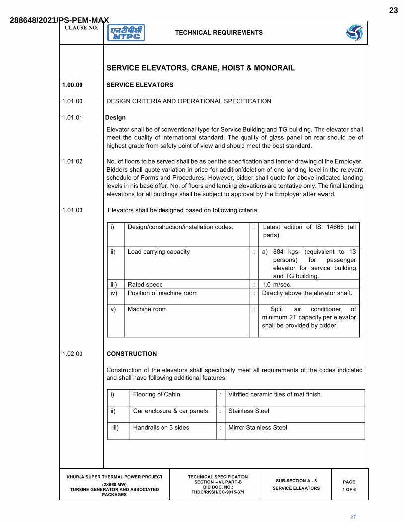
SERVICE ELEVATORS, CRANE, HOIST & MONORAIL
1.00.00 SERVICE ELEVATORS
1.01.00 DESIGN CRITERIA AND OPERATIONAL SPECIFICATION
1.01.01 Design
Elevator shall be of conventional type for Service Building and TG building. The elevator shall
meet the quality of international standard. The quality of glass panel on rear should be of
highest grade from safety point of view and should meet the best standard.
1.01.02 No. of floors to be served shall be as per the specification and tender drawing of the Employer.
Bidders shall quote variation in price for addition/deletion of one landing level in the relevant
schedule of Forms and Procedures. However, bidder shall quote for above indicated landing
levels in his base offer. No. of floors and landing elevations are tentative only. The final landing
elevations for all buildings shall be subject to approval by the Employer after award.
1.01.03 Elevators shall be designed based on following criteria:
i) Design/construction/installation codes. : Latest edition of IS: 14665 (all
parts)
ii) Load carrying capacity : a) 884 kgs. (equivalent to 13
persons) for passenger
elevator for service building
and TG building.
iii) Rated speed : 1.0 m/sec.
iv) Position of machine room : Directly above the elevator shaft.
v) Machine room : Window air conditioner of
minimum 2T capacity per elevator
shall be provided by bidder.
1.02.00 CONSTRUCTION
Construction of the elevators shall specifically meet all requirements of the codes indicated
and shall have following additional features:
i) Flooring of Cabin : Vitrified ceramic tiles of mat finish.
ii) Car enclosure & car panels : Stainless Steel
iii) Handrails on 3 sides : Mirror Stainless Steel
21
Split
288648/2021/PS-PEM-MAX23

CLAUSE NO.TECHNICAL REQUIREMENTS
KHURJA SUPER THERMAL POWER PROJECT (2X660 MW)
TURBINE GENERATOR AND ASSOCIATED PACKAGES
TECHNICAL SPECIFICATION SECTION VI, PART-B
BID DOC. NO.: THDC/RKSH/CC-9915-371
SUB-SECTION A - 8SERVICE ELEVATORS
PAGE2 OF 6
iv) False ceiling : Powder painted
v) Car opening & Hoist way
opening
: Protected by central opening sliding Stainless
Steel door
vi) CABIN ACCESSORIES : The following accessories shall be provided :
a) Recessed fluorescent light fittings on car
floor.
b) Car control station
c) Emergency stop switch.
d) 5/15A, 3 pin plug socket with switch on top
of lift car.
e) Switches with Braille characters.
1. AUTOMATIC RESCUE DEVICE (ARD) - (BATTERY DRIVE):
2. EMERGENCY SAFETY DEVICES :
The lift shall be provided with safety Device attached to the lift car frame and placed
beneath the car. The safety device shall be capable of stopping and sustaining the lift
car up at governor tripping speed with full rated load in car.
3. Elevator shall have Floor announcement system & Braille switches
1.02.01 All steel embedment for fixing landing doors/indicators etc. to the Elevator well shaft and fascia
plate shall be supplied by the Bidder.
1.02.02 Guide rails complete with supporting brackets for the car and counter weights. Bidder to take
care of granite tiles (approx 80 kg) to be provided for cabin flooring in selecting counter weights.
1.02.03 Elevator drive machines complete with electric motor, reduction gear unit, suspension ropes,
buffers for the cars and the counter weights and other drive and control mechanism. All
foundation anchor bolts, sleeves, anchoring steel and any item required to complete the job
satisfactorily shall be provided by the bidder. The bidder shall also provide for the grouting of
anchor bolts, sleeves, anchoring steel, etc. and other anchorages
1.02.04 Any other steel works as well as all other accessories/components not specified in the
specification but necessary for making the Elevator complete.
22
Safety device in form of limit switches are placed below the lift car to stop and sustain the lift car. Further, safety governors are also installed on sides of car which come in operation during free fall of elevator or when speeds are higher than trip-ping speeds. During above mentioned situations safety governor gradually hold the guiderail and bring the elevator to complete rest.
(if the material of construction of false ceiling is other than SS 304.)
LED
288648/2021/PS-PEM-MAX24

CLAUSE NO.TECHNICAL REQUIREMENTS
KHURJA SUPER THERMAL POWER PROJECT (2X660 MW)
TURBINE GENERATOR AND ASSOCIATED PACKAGES
TECHNICAL SPECIFICATION SECTION VI, PART-B
BID DOC. NO.: THDC/RKSH/CC-9915-371
SUB-SECTION A - 8SERVICE ELEVATORS
PAGE3 OF 6
1.02.05 All building work including the supply of steel items, associated with installation of equipment
in the machine room hoist way, hoist way door, frames and Elevator pit, shall form part of
bidders scope of service, Bidder shall also provide the Elevator-well complete with foundation
and brick walls around the lit-well together with overhead machine room. The machine room
will be provided with R.C.C. floor slab with necessary pockets for anchor bolts and slots.
1.03.00 OPERATION
1.03.01 Elevator shall have provisions to meet following operational requirements :
a) Selective Duplex collective, automatic operation with or without attendant through
illuminated push button station located inside the lift car.
b) Door operating shall be automatic door operation and electronic door protection
system for opening/closing of car and landing doors.
c) Bidder shall provide car operating panel with luminous buttons, car position indication
in car (both visual and audio) combined with direction arrows, overload warning
indicator, battery operated alarm bell and emergency light and fan & hands free
speaker telephone set with suitable battery, charger & controls.
d) Bidder shall provide emergency indicator to indicate the location of elevator in case of
elevator being stuck up between the floors through automatic flashers (both audio &
visual)
e) Bidder shall provide electronic door detector (Infra red curtain type).
f) Two push buttons, one for upward movement and the other for downward movement
at each intermediate landing and one push button at each terminal landing shall be
provided in order to call the car. Digital hall position indicator at all floors, tell lights at
all floors shall also be provided by the bidder.
g) For facilitating the movement of visually & hearing impaired persons, hall lantern and car arrival chimes shall be provided.
h) All fixtures shall be in stainless steel face plates.
i) Push buttons shall be fixed in the car for holding the doors open for any length of the
time required.
j) All other safety/protection/operation interlocks as required by IS:14665 (latest edition).
23
288648/2021/PS-PEM-MAX25

CLAUSE NO.TECHNICAL REQUIREMENTS
KHURJA SUPER THERMAL POWER PROJECT (2X660 MW)
TURBINE GENERATOR AND ASSOCIATED PACKAGES
TECHNICAL SPECIFICATION SECTION VI, PART-B
BID DOC. NO.: THDC/RKSH/CC-9915-371
SUB-SECTION A - 8SERVICE ELEVATORS
PAGE4 OF 6
1.04.00 Elevator Electricals:
1.04.01 Electric motor:
The driving motors shall conform to I.S 325 and suitable for the Variable Voltage Variable Frequency (VVVF) application. All motors shall be squirrel cage induction type, suitable for operation at 415V (+/- 10% variation) , 3 phase, 3 wire, 50HZ (+3% to -5% variation) supply. Motors shall be provided with thermal class 130 (B) or better insulation.
1.04.02 Controls:
The controls shall be Variable Voltage and Variable frequency type and shall provide smooth
and constant acceleration and retardation under all conditions of operation. Suitable control
panel shall be provided in the machine room.
1.04.03 Cables and wiring:
All the cables except trailing cables shall be as per IS:1554-1 or IS-7098-I. the PVC outer
sheath of these cables shall be flame retardant, low smoke (FRLS) type with the following
FRLS properties.
a) Oxygen index of min. 29 (as per IS:10810 Part-58)
b) Acid gas emission of max. 20% (as per IEC-754-I).
c) Smoke density rating shall not be more than 60% (as per ASTMD-2843).
The circular trailing cables shall be either in accordance with IS 4289 Part-I (Elastomer
insulated) or IS-4289 Part-II (PVC insulated). The flat type trailing cables if offered shall be in
accordance with IEC-60227-6.
All wiring / cabling between the equipments in the lift machine room and that between the
machine room and equipments in the lift well and at the landings shall be wired in HDP
conduits/ galvanized steel conduits to be supplied by the contractor. Alternatively armored
cables may be used.
1.04.04 Earthing:
The elevator structures and all Electrical equipment, including metal conduits shall be
effectively earthed with the earth conductors provided in the machine room as per IS: 3043.
24
288648/2021/PS-PEM-MAX26
CLAUSE NO.TECHNICAL REQUIREMENTS
KHURJA SUPER THERMAL POWER PROJECT (2X660 MW)
TURBINE GENERATOR AND ASSOCIATED PACKAGES
TECHNICAL SPECIFICATION SECTION VI, PART-B
BID DOC. NO.: THDC/RKSH/CC-9915-371
SUB-SECTION A - 8SERVICE ELEVATORS
PAGE5 OF 6
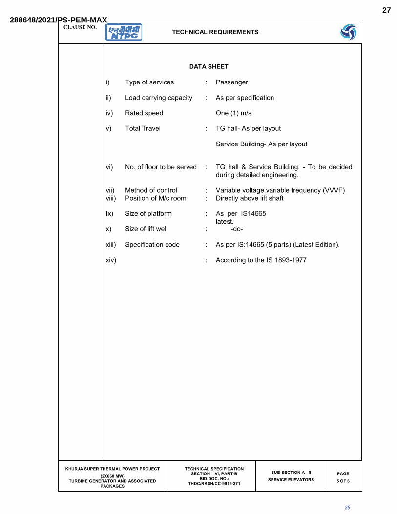
DATA SHEET
i) Type of services : Passenger
ii) Load carrying capacity : As per specification
iv) Rated speed One (1) m/s
v) Total Travel : TG hall- As per layout
Service Building- As per layout
vi) No. of floor to be served : TG hall & Service Building: - To be decided during detailed engineering.
vii) Method of control : Variable voltage variable frequency (VVVF)viii) Position of M/c room : Directly above lift shaft
Ix) Size of platform :latest.
x) Size of lift well : -do-
xiii) Specification code : As per IS:14665 (5 parts) (Latest Edition).
xiv) : According to the IS 1893-1977
25
288648/2021/PS-PEM-MAX27

2X660 MW KHURJA STPP
TECHNICAL SPECIFICATION FOR ELEVATOR
SPECIFIC TECHNICAL REQUIREMENT -MECHANICAL
SPECIFICATION No: PE-TS-475-502-A001 SECTION IA REV. 00 APR 2021
GENERAL TECHNICAL REQUIREMENT
26
(AS PER APPLICABILITY OF SCOPE DEFINED IN SECTION IA)
288648/2021/PS-PEM-MAX28

KHURJA SUPER THERMAL POWER PROJECT (2X660 MW)
TURBINE GENERATOR AND ASSOCIATED PACKAGES BID DOC. NO.: THDC/RKSH/CC-9915-371
SEPARATOR
PART – C
GENERAL TECHNICAL REQUIREMENT (GTR)
27
288648/2021/PS-PEM-MAX29

CLAUSE NO. GENERAL TECHNICAL REQUIREMENTS
KHURJA SUPER THERMAL POWER PROJECT (2X660 MW)
TURBINE GENERATOR AND ASSOCIATED PACKAGES
TECHNICAL SPECIFICATIONSECTION – VI, PART-B
BID DOC. NO.: THDC/RKSH/CC-9915-371CONTENTS
PAGE1 OF 1
PART - C
CONTENTS
Clause No. Description1.00.00 Introduction
2.00.00 Brand Name
3.00.00 Base Offer & Alternate Proposals
4.00.00 Completeness of Facilities
5.00.00 Codes & Standards
6.00.00 Equipment Functional Guarantee
7.00.00 Design of Facilities/ Maintenance & Availability Considerations
8.00.00 Documents, Data and Drawings to be furnished by Contractor
9.00.00 Quality Assurance Programme
10.00.00 Pre-commissioning and Commissioning Facilities
11.00.00 Guarantee Tests
12.00.00 Taking over
13.00.00 Training Of Employer's Personnel
14.00.00 Safety Aspects During Construction And Erection
15.00.00 Noise Level
16.00.00 Packaging and Transportation
17.00.00 Electrical Enclosure
18.00.00 Instrumentation and Control
19.00.00 Electrical Noise Control
20.00.00 Instrument Air System
21.00.00 Tapping Points for Measurements
22.00.00 System Documentation
23.00.00 Maintenance Manuals of Electronic Modules
Annexure - IAnnexure - IIAnnexure - IIIAnnexure - IVAnnexure - V
28
288648/2021/PS-PEM-MAX30
CLAUSE NO.
GENERAL TECHNICAL REQUIREMENTS
KHURJA SUPER THERMAL POWER PROJECT (2X660 MW)
TURBINE GENERATOR AND ASSOCIATED PACKAGES
TECHNICAL SPECIFICATIONSECTION – VI, PART-C
BID DOC. NO.: THDC/RKSH/CC-9915-371
GENRAL TECHNICAL REQUIREMENTS (GTR)
PAGE1 OF 89
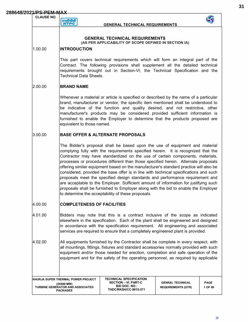
GENERAL TECHNICAL REQUIREMENTS
1.00.00 INTRODUCTION
This part covers technical requirements which will form an integral part of the
Contract. The following provisions shall supplement all the detailed technical
requirements brought out in Section-VI, the Technical Specification and the
Technical Data Sheets.
2.00.00 BRAND NAME
Whenever a material or article is specified or described by the name of a particular
brand, manufacturer or vendor, the specific item mentioned shall be understood to
be indicative of the function and quality desired, and not restrictive, other
manufacturer's products may be considered provided sufficient information is
furnished to enable the Employer to determine that the products proposed are
equivalent to those named.
3.00.00 BASE OFFER & ALTERNATE PROPOSALS
The Bidder's proposal shall be based upon the use of equipment and material
complying fully with the requirements specified herein. It is recognized that the
Contractor may have standardized on the use of certain components, materials,
processes or procedures different than those specified herein. Alternate proposals
offering similar equipment based on the manufacturer's standard practice will also be
considered, provided the base offer is in line with technical specifications and such
proposals meet the specified design standards and performance requirement and
are acceptable to the Employer. Sufficient amount of information for justifying such
proposals shall be furnished to Employer along with the bid to enable the Employer
to determine the acceptability of these proposals.
4.00.00 COMPLETENESS OF FACILITIES
4.01.00 Bidders may note that this is a contract inclusive of the scope as indicated
elsewhere in the specification. Each of the plant shall be engineered and designed
in accordance with the specification requirement. All engineering and associated
services are required to ensure that a completely engineered plant is provided.
4.02.00 All equipments furnished by the Contractor shall be complete in every respect, with
all mountings, fittings, fixtures and standard accessories normally provided with such
equipment and/or those needed for erection, completion and safe operation of the
equipment and for the safety of the operating personnel, as required by applicable
29
(AS PER APPLICABILITY OF SCOPE DEFINED IN SECTION IA)
288648/2021/PS-PEM-MAX31

CLAUSE NO.
GENERAL TECHNICAL REQUIREMENTS
KHURJA SUPER THERMAL POWER PROJECT (2X660 MW)
TURBINE GENERATOR AND ASSOCIATED PACKAGES
TECHNICAL SPECIFICATIONSECTION – VI, PART-C
BID DOC. NO.: THDC/RKSH/CC-9915-371
GENRAL TECHNICAL REQUIREMENTS (GTR)
PAGE2 OF 89
codes, though they may not have been specifically detailed in the respective
specifications, unless included in the list of exclusions.
All same standard components/ parts of same equipment provided, shall be
interchangeable with one another.
4.03.00 For the C&I systems, the Contractor shall be required to provide regular information
about future upgrades and migration paths to the Employer.
5.00.00 CODES & STANDARDS
5.01.00 In addition to the codes and standards specifically mentioned in the relevant
technical specifications for the equipment / plant / system, all equipment parts,
systems and works covered under this specification shall comply with all currently
applicable statutory regulations and safety codes of the Republic of India, as well as
of the locality where they will be installed, including the following:
(a.) Indian electricity act
(b.) Indian electricity rules
(c.) Indian Explosives Act
(d.) Indian Factories Act and State Factories Act
(e) Indian Boiler Regulations (IBR)
(f.) Regulations of the Central Pollution Control Board, India
(g.) Regulations of the Ministry of Environment & Forest (MoEF), Government of
India
(h) Pollution Control Regulations of Department of Environment, Government of
India
(i.) State Pollution Control Board.
(j.) Rules for Electrical installation by Tariff Advisory Committee (TAC).
(k.) Building and other construction workers (Regulation of Employment and
Conditions of services) Act, 1996
30
288648/2021/PS-PEM-MAX32

CLAUSE NO.
GENERAL TECHNICAL REQUIREMENTS
KHURJA SUPER THERMAL POWER PROJECT (2X660 MW)
TURBINE GENERATOR AND ASSOCIATED PACKAGES
TECHNICAL SPECIFICATIONSECTION – VI, PART-C
BID DOC. NO.: THDC/RKSH/CC-9915-371
GENRAL TECHNICAL REQUIREMENTS (GTR)
PAGE3 OF 89
(l.) Building and other construction workers (Regulation of Employment and
Conditions of services) Central Rules, 1998
(m.) Explosive Rules, 1983
(n.) Petroleum Act, 1984
(o.) Petroleum Rules, 1976,
(p.) Gas Cylinder Rules, 1981
(q.) Static and Mobile Pressure Vessels (Unified) Rules, 1981
(r.) Workmen's Compensation Act, 1923
(s.) Workmen's Compensation Rules, 1924
(t.) NTPC Safety Rules for Construction and Erection
(u.) NTPC Safety Policy
(v.) Any other statutory codes / standards / regulations, as may be applicable.
5.02.00 Unless covered otherwise in the specifications, the latest editions (as applicable as
on date of bid opening), of the codes and standards given below shall also apply:
(a) Bureau of Indian Standards (BIS)
(b.) Japanese Industrial Standards (JIS)
(c.) American National Standards Institute (ANSI)
(d.) American Society of Testing and Materials (ASTM)
(e.) American Society of Mechanical Engineers (ASME)
(f.) American Petroleum Institute (API)
(g.) Standards of the Hydraulic Institute, U.S.A.
(h.) International Organisation for Standardization (ISO)
(i.) Tubular Exchanger Manufacturer's Association (TEMA)
31
288648/2021/PS-PEM-MAX33

CLAUSE NO.
GENERAL TECHNICAL REQUIREMENTS
KHURJA SUPER THERMAL POWER PROJECT (2X660 MW)
TURBINE GENERATOR AND ASSOCIATED PACKAGES
TECHNICAL SPECIFICATIONSECTION – VI, PART-C
BID DOC. NO.: THDC/RKSH/CC-9915-371
GENRAL TECHNICAL REQUIREMENTS (GTR)
PAGE4 OF 89
(j.) American Welding Society (AWS)
(k.) National Electrical Manufacturers Association (NEMA)
(l.) National Fire Protection Association (NFPA)
(m.) International Electro-Technical Commission (IEC)/European Norm (EN)
(n.) Expansion Joint Manufacturers Association (EJMA)
(o.) Heat Exchange Institute (HEI)
p) IEEE standard
q) JEC standard
5.03.00 Other International/ National standards such as DIN, VDI, BS, GOST etc. shall also
be accepted for only material codes and manufacturing standards, subject to the
Employer's approval, for which the Bidder shall furnish, adequate information to
justify that these standards are equivalent or superior to the standards mentioned
above. In all such cases the Bidder shall furnish specifically the variations and
deviations from the standards mentioned else where in the specification together
with the complete word to word translation of the standard that is normally not
published in English.
5.04.00 As regards highly standardized equipments such as Steam Turbine and Generator,
National /International standards such as JIS, DIN, VDI, ISO, SEL, SEW, VDE, IEC
& VGB shall also be considered as far as applicable for Design, Manufacturing and
Testing of the respective equipment. However, for those of the above equipment not
covered by these National / International standards, established and proven
standards of manufacturers shall also be considered.
5.05.00 In the event of any conflict between the codes and standards referred to in the
above clauses and the requirement of this specification, the requirement of
Technical Specification shall govern.
5.06.00 Two (2) English language copies of all-national and international codes and/or
standards used in the design of the plant, equipment, and structural works shall be
provided by the Contractor to the Employer within two calendar months from the
date of the Notification of Award.
5.07.00 In case of any change in codes, standards & regulations between the date of bid
opening and the date when vendors proceed with fabrication, the Employer shall
32
288648/2021/PS-PEM-MAX34

CLAUSE NO.
GENERAL TECHNICAL REQUIREMENTS
KHURJA SUPER THERMAL POWER PROJECT (2X660 MW)
TURBINE GENERATOR AND ASSOCIATED PACKAGES
TECHNICAL SPECIFICATIONSECTION – VI, PART-C
BID DOC. NO.: THDC/RKSH/CC-9915-371
GENRAL TECHNICAL REQUIREMENTS (GTR)
PAGE5 OF 89
have the option to incorporate the changed requirements or to retain the original
standard. It shall be the responsibility of the Contractor to bring to the notice of the
Employer such changes and advise Employer of the resulting effect.
6.00.00 EQUIPMENT FUNCTIONAL GUARANTEE
6.01.00 The functional guarantees of the equipment under the scope of the Contract is given
in Section-VI Part - A & B of technical specification .These guarantees shall
supplement the general functional guarantee provisions covered under General
Conditions of Contract.
6.02.00 Liquidated damages for shortfall in meeting functional guarantee(s) during the
performance and guarantee tests shall be assessed and recovered from the
Contractor as specified elsewhere in this specification.
7.00.00 DESIGN OF FACILITIES/ MAINTENANCE & AVAILABILITY CONSIDERATIONS
7.01.00 Design of Facilities
All the design procedures, systems and components proposed shall have already
been adequately developed and shall have demonstrated good reliability under
similar conditions elsewhere.
The Contractor shall be responsible for the selection and design of appropriate
equipments to provide the best co-ordinated performance of the entire system. The
basic requirements are detailed out in various clauses of the Technical
Specifications. The design of various components, assemblies and subassemblies
shall be done so that it facilitates easy field assembly and dismantling. All the
rotating components shall be so selected that the natural frequency of the complete
unit is not critical or close to the operating range of the unit.
7.02.00 Maintenance and Availability Considerations
Equipment/works offered shall be designed for high availability, low maintenance
and ease of maintenance. The Bidder shall specifically state the design features
incorporated to achieve high degree of reliability/ availability and ease of
maintenance. The Bidder shall also furnish details of availability records in the
reference plants stated in his experience list.
Bidder shall state in his offer the various maintenance intervals, spare parts and
man-hour requirement during such operation. The intervals for each type of
maintenance namely inspection of the turbine and equipments, inspection of the
33
288648/2021/PS-PEM-MAX35

CLAUSE NO.
GENERAL TECHNICAL REQUIREMENTS
KHURJA SUPER THERMAL POWER PROJECT (2X660 MW)
TURBINE GENERATOR AND ASSOCIATED PACKAGES
TECHNICAL SPECIFICATIONSECTION – VI, PART-C
BID DOC. NO.: THDC/RKSH/CC-9915-371
GENRAL TECHNICAL REQUIREMENTS (GTR)
PAGE6 OF 89
steam path and the minor and major overhauls shall be specified in terms of running
hours, clearly defining the spare parts and manhour requirement for each stage.
Lifting devices i.e. hoists and chain pulley jacks, etc. shall be provided by the
contractor for handling of any equipment or any of its part having weight in excess of
500 Kgs during erection and maintenance activities.
Lifting devices like lifting tackles, slings, etc. to be connected to hook of the hoist /
crane shall be provided by the contractor for lifting the equipment and accessories
covered under the specification.
8.00.00 DOCUMENTS, DATA AND DRAWINGS TO BE FURNISHED BY CONTRACTOR
8.01.00 Bidders may note that this is a contract inclusive of the scope as indicated
elsewhere in the specification. Each of the plant and equipment shall be fully
integrated, engineered and designed to perform in accordance with the technical
specification. All engineering and technical services required to ensure a completely
engineered plant shall be provided in respect of mechanical, electrical, control &
instrumentation, civil & structural works as per the scope.
Each main and auxiliary equipment/item of the plant including instruments shall be
assigned a unique tag number. The assignment of tag numbers shall be in
accordance with KKS system. In all drawings/documents/data sheet etc. KKS tag
number of the equipment/item/instrument etc. shall be indicated.
The Contractor shall furnish engineering data/drawings. in accordance with the
schedule of information as specified in Technical Specification and Technical data
sheet.
8.02.00 The number of copies/prints/CD-ROMs/manuals to be furnished for various types of
documents is given in Annexure-I to this Part-C, Section-VI of the Technical
Specification.
8.03.00 The documentation that shall be provided by the Contractor is indicated in thvarious
sections of specification. This documentation shall include but not be limited to the
following :
8.03.01
(a.) BASIC ENGINEERING DOCUMENTATION
34
288648/2021/PS-PEM-MAX36

CLAUSE NO.
GENERAL TECHNICAL REQUIREMENTS
KHURJA SUPER THERMAL POWER PROJECT (2X660 MW)
TURBINE GENERATOR AND ASSOCIATED PACKAGES
TECHNICAL SPECIFICATIONSECTION – VI, PART-C
BID DOC. NO.: THDC/RKSH/CC-9915-371
GENRAL TECHNICAL REQUIREMENTS (GTR)
PAGE7 OF 89
Prior to commencement of the detailed engineering work, the Contractor
shall furnish a Plant Definition Manual within 12 weeks from the date of the
Notification of Award. This manual shall contain the following as a minimum:
i. System description of all the mechanical, electrical, control &
instrumentation & civil systems.
ii. Technology scan for each system / sub-system & equipment.
iii. Selection of appropriate technology / schemes for various systems/
subsystems including techno-economic studies between various
options.
iv. Optimization studies including thermal cycle optimization.
v. Sizing criteria of all the systems, sub-systems including various piping
systems/ equipments/ structures/ equipment foundations alongwith all
calculations justifying and identifying the sizing and the design
margins.
vi. Schemes and Process & Instrumentation diagrams for the various
systems/ sub-system with functional write-ups.
vii. Operation Philosophy and the control philosophy of the equipments /
system covered under the scope.
viii. General Layout plan of the power station incorporating all facilities in
Contractor's as well as those in the Employer's scope. This drawing
shall also be furnished in the form of CD-ROMs to the Employer for
engineering of areas not included in bidder's scope.
ix. Basic layouts and cross sections of the TG building (various floor
elevations), and other areas included in the scope of thebidder.
x. Documentation in respect of Quality Assurance System as listed out
elsewhere in this specification.
The successful bidder shall furnish within three (3) weeks from the date of
Notification of Award, a list of contents of the Plant Definition Manual
(PDMs) including techno-economic studies, which shall then be
mutually discussed & finalised with the Employer.
35
288648/2021/PS-PEM-MAX37
CLAUSE NO.
GENERAL TECHNICAL REQUIREMENTS
KHURJA SUPER THERMAL POWER PROJECT (2X660 MW)
TURBINE GENERATOR AND ASSOCIATED PACKAGES
TECHNICAL SPECIFICATIONSECTION – VI, PART-C
BID DOC. NO.: THDC/RKSH/CC-9915-371
GENRAL TECHNICAL REQUIREMENTS (GTR)
PAGE8 OF 89
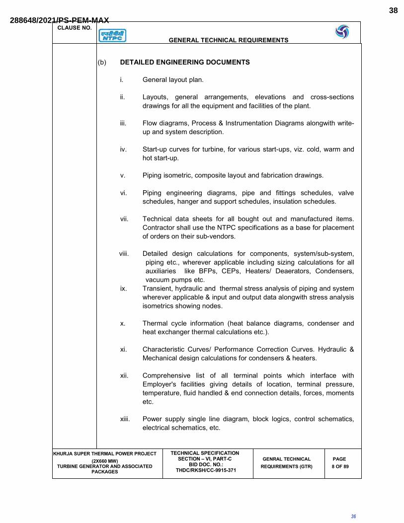
(b) DETAILED ENGINEERING DOCUMENTS
i. General layout plan.
ii. Layouts, general arrangements, elevations and cross-sections
drawings for all the equipment and facilities of the plant.
iii. Flow diagrams, Process & Instrumentation Diagrams alongwith write-
up and system description.
iv. Start-up curves for turbine, for various start-ups, viz. cold, warm and
hot start-up.
v. Piping isometric, composite layout and fabrication drawings.
vi. Piping engineering diagrams, pipe and fittings schedules, valve
schedules, hanger and support schedules, insulation schedules.
vii. Technical data sheets for all bought out and manufactured items.
Contractor shall use the NTPC specifications as a base for placement
of orders on their sub-vendors.
viii. Detailed design calculations for components, system/sub-system,
piping etc., wherever applicable including sizing calculations for all
auxiliaries like BFPs, CEPs, Heaters/ Deaerators, Condensers,
vacuum pumps etc.
ix. Transient, hydraulic and thermal stress analysis of piping and system
wherever applicable & input and output data alongwith stress analysis
isometrics showing nodes.
x. Thermal cycle information (heat balance diagrams, condenser and
heat exchanger thermal calculations etc.).
xi. Characteristic Curves/ Performance Correction Curves. Hydraulic &
Mechanical design calculations for condensers & heaters.
xii. Comprehensive list of all terminal points which interface with
Employer's facilities giving details of location, terminal pressure,
temperature, fluid handled & end connection details, forces, moments
etc.
xiii. Power supply single line diagram, block logics, control schematics,
electrical schematics, etc.
36
288648/2021/PS-PEM-MAX38

CLAUSE NO.
GENERAL TECHNICAL REQUIREMENTS
KHURJA SUPER THERMAL POWER PROJECT (2X660 MW)
TURBINE GENERATOR AND ASSOCIATED PACKAGES
TECHNICAL SPECIFICATIONSECTION – VI, PART-C
BID DOC. NO.: THDC/RKSH/CC-9915-371
GENRAL TECHNICAL REQUIREMENTS (GTR)
PAGE9 OF 89
xiv. Protection system diagrams and relay settings.
xv. Interconnection diagrams.
xvi. Cable routing plan.
xvii. Instrument schedule, measuring point list, I/O list, Interconnection &
wiring diagram, functional write-ups, installation drawings for field
mounted instruments, logic diagrams, control schematics, wiring and
tubing diagrams of panels and enclosures etc. Drawings for open
loop and close loop controls (both hardware and software). Motor list
and valve schedule including type of actuator etc.
xviii. Alarm and annunciation list / Sequence of Event (SOE) list and
alarms & trip set points.
xix. Sequence and protection interlock schemes.
xx. Type test reports and power system stability study report.
xxi. Control system configuration diagrams.
xxii. Detailed DDCMIS system manuals
xxiii. Detailed flow chart for digital control system.
xxiv. Mimic diagram layout, Assignment for other application engg.
xxv. Civil & Structural works drawings and documents for all structures,
facilities, foundations, underground and overground works and super-
structural works as included in the scope of the Bidder.
xxvi. Model study reports wherever applicable.
xxvii. Functional & guarantee test procedures and test reports.
xxviii. Documentation in respect of Quality Assurance System as listed out
elsewhere in this specification.
xxix. Documentation in respect of commissioning as listed out elsewhere in
this specification.
37
288648/2021/PS-PEM-MAX39

CLAUSE NO.
GENERAL TECHNICAL REQUIREMENTS
KHURJA SUPER THERMAL POWER PROJECT (2X660 MW)
TURBINE GENERATOR AND ASSOCIATED PACKAGES
TECHNICAL SPECIFICATIONSECTION – VI, PART-C
BID DOC. NO.: THDC/RKSH/CC-9915-371
GENRAL TECHNICAL REQUIREMENTS (GTR)
PAGE10 OF 89
The Contractor while submitting the above documents / drawings for
approval / reference as the case may be, shall mark on each copy of
submission the reference letter alongwith the date vide which the
submissions are made.
8.03.02 INSTRUCTION MANUALS
The Contractor shall submit to the Employer, draft instruction manuals for all the
equipments covered under the Contract by the end of one year from the date of his
acceptance of the Letter of Award.The Instruction manuals shall contain full details
required for erection, commissioning, operation and maintenance of each
equipment. The manual shall be specifically compiled for this project. After
finalization and approval of the Employer the Instruction Manuals shall be submitted
as indicated in Annexure-I. The Contract shall not be considered to be completed for
purposes of taking over until the final Instructions manuals have been supplied to the
Employer. The Instruction Manuals shall comprise of the following.
(a.) Erection Manuals
The erection manuals shall be submitted atleast three (3) months prior to the
commencement of erection activities of particular equipment/system. The
erection manual should contain the following as a minimum.
a) Erection strategy.
b) Sequence of erection.
c) Erection instructions.
d) Critical checks and permissible deviation/tolerances.
e) List of tool, tackles, heavy equipments like cranes, dozers, etc.
f) Bill of Materials
g) Procedure for erection .
h) General safety procedures to followed during erection/installation.
i) Procedure for initial checking after erection.
j) Procedure for testing and acceptance norms.
38
288648/2021/PS-PEM-MAX40

CLAUSE NO.
GENERAL TECHNICAL REQUIREMENTS
KHURJA SUPER THERMAL POWER PROJECT (2X660 MW)
TURBINE GENERATOR AND ASSOCIATED PACKAGES
TECHNICAL SPECIFICATIONSECTION – VI, PART-C
BID DOC. NO.: THDC/RKSH/CC-9915-371
GENRAL TECHNICAL REQUIREMENTS (GTR)
PAGE11 OF 89
k) Procedure / Check list for pre-commissioning activities.
l) Procedure / Check list for commissioning of the system.
m) Safety precautions to be followed in electrical supply distribution
during erection
(b.) Operation & Maintenance Manuals
a) The manual shall be a two rim PVC bound stiff sided binder able to
withstand constant usage or where a thicker type is required it shall
have locking steel pins, the size of the manual shall not be larger than
international size A3. The cover shall be printed with the Project
Name, Services covered and Volume / Book number Each section of
the manual shall be divided by a stiff divider of the same size as the
holder. The dividers shall clearly state the section number and title.
All written instructions within the manual not provided by the
manufacturers shall be typewritten with a margin on the left hand
side.
b) The arrangement and contents of O & M manuals shall be as follows :
1) Chapter 1 - Plant Description : To contain the following
sections specific to the
equipment/system
supplied
(a) Description of operating principle of equipment / system with
schematic drawing / layouts.
(b) Functional description of associated accessories / controls. Control
interlock protection write up.
(c) Integrated operation of the equipment alongwith the intended system.
(The is to be given by the supplier of the Main equipment by taking
into account the operating instruction given by the associated
suppliers).
(d) Exploded view of the main equipment, associated accessories and
auxiliaries with description. Schematic drawing of the equipment
alongwith its accessories and auxiliaries.
39
288648/2021/PS-PEM-MAX41
CLAUSE NO.
GENERAL TECHNICAL REQUIREMENTS
KHURJA SUPER THERMAL POWER PROJECT (2X660 MW)
TURBINE GENERATOR AND ASSOCIATED PACKAGES
TECHNICAL SPECIFICATIONSECTION – VI, PART-C
BID DOC. NO.: THDC/RKSH/CC-9915-371
GENRAL TECHNICAL REQUIREMENTS (GTR)
PAGE12 OF 89
(e) Design data against which the plant performance will be compared.
(f) Master list of equipments, Technical specification of the equipment/
system and approved data sheets.
(g) Identification system adopted for the various components, (it will be of
a simple process linked tagging system).
(h) Master list of drawings (as built drawing - Drawings to be enclosed in
a separate volume).
2) Chapter 2.0 - Plant Operation: To contain the following sections specific to the
equipment supplied
(a) Protection logics provided for the equipment alongwith brief
philosophy behind the logic, Drawings etc.
(b) Limiting values of all protection settings.
(c) Various settings of annunciation/interlocks provided.
(d) Startup and shut down procedure for equipment alongwith the
associated systems in step mode.
(e) Do's and Don'ts related to operation of the equipment.
(f) Safety precautions to be take during normal operation. Emergency
instruction on total power failure condition/lubrication failure/any other
conditions.
(g) Parameters to be monitored with normal value and limiting values.
(h) Equipment isolating procedures.
(i) Trouble shooting with causes and remedial measures.
(j) Routine testing procedure to ascertain healthiness of the safety
devices alongwith schedule of testing.
(k) Routine Operational Checks, Recommended Logs and Records
(l) Change over schedule if more than one auxiliary for the same
purpose is given.
40
288648/2021/PS-PEM-MAX42

CLAUSE NO.
GENERAL TECHNICAL REQUIREMENTS
KHURJA SUPER THERMAL POWER PROJECT (2X660 MW)
TURBINE GENERATOR AND ASSOCIATED PACKAGES
TECHNICAL SPECIFICATIONSECTION – VI, PART-C
BID DOC. NO.: THDC/RKSH/CC-9915-371
GENRAL TECHNICAL REQUIREMENTS (GTR)
PAGE13 OF 89
(m) Preservation procedure on long shut down.
(n) System/plant commissioning procedure.
3) Chapter 3.0 - Plant Maintenance- To contain the following sections specific to
the equipment supplied.
(a) Exploded view of each of the equipments. Drawings alongwith bill of
materials including name, code no. & population.
(b) Exploded view of the spare parts and critical components with
dimensional drawings (In case of Electronic cards, the circuit diagram
to be given) and spare parts catalogue for each equipment.
(c) List of Special T/ P required for Overhauling /Trouble shooting
including special testing equipment required for calibration etc.
(d) Stepwise dismantling and assembly procedure clearly specifying the
tools to be used, checks to be made, records to be maintained etc.
Clearance to be maintained etc.
(e) Preventive Maintenance schedules linked with running
hours/calendar period alongwith checks to be carried out.
(f) Overhauling schedules linked with running hours/calendar period
alongwith checks to be done.
(g) Long term maintenance schedules
(h) Consumables list alongwith the estimated quantity required during
normal running and during maintenance like Preventive Maintenance
and Overhauling.
(i) List of lubricants with their Indian equivalent, Lubrication Schedule
including charts showing lubrication checking, testing and
replacement procedure to be carried daily, weekly, monthly & at
longer intervals to ensure trouble free operation and quantity required
for complete replacement..
(j) Tolerance for fitment of various components.
(k) Details of sub vendors with their part no. in case of bought out items.
41
288648/2021/PS-PEM-MAX43

CLAUSE NO.
GENERAL TECHNICAL REQUIREMENTS
KHURJA SUPER THERMAL POWER PROJECT (2X660 MW)
TURBINE GENERATOR AND ASSOCIATED PACKAGES
TECHNICAL SPECIFICATIONSECTION – VI, PART-C
BID DOC. NO.: THDC/RKSH/CC-9915-371
GENRAL TECHNICAL REQUIREMENTS (GTR)
PAGE14 OF 89
(l) List of spare parts with their Part No, total population, life expediency
& their interchangeability with already supplied spares to NTPC.
(m) List of mandatory and recommended spare list along with
manufacturing drawings, material specification & quality plan for fast
moving consumable spares.
(n) Lead time required for ordering of spares from the equipment
supplier, instructions for storage and preservation of spares.
(o) General information on the equipment such as modification carried
out in the equipment from its inception, equipment population in the
country / foreign country and list of utilities where similar equipments
have been supplied.
8.03.03 After finalization and approval of the Employer, the O & M Manuals shall be
submitted as indicated in Annexure-VI. The Contract shall not be considered to be
completed for purposes of taking over until the final Instructions manuals (both
erection and O & M manuals have been supplied to the Employer.
If after the commissioning and initial operation of the plant, the instruction manuals
(Erection and /or O &M manuals) require modifications/additions/ changes, the same
shall be incorporated and the updated final instruction manuals shall be submitted by
the Contractor to the Employer for records and number of copies shall be as
mentioned in Annexure-VI.
8.03.03 PLANT HANDBOOK AND PROJECT COMPLETION REPORT
(a.) PLANT HANDBOOK
The Contractor shall submit to the Employer a preliminary plant hand book
preferably in A-4 size sheets which shall contain the design and performance data of
various plants, equipments and systems covering the complete project including
1. Design and performance data.
2. Process & Instrumentation diagrams.
3. Single line diagrams.
42
288648/2021/PS-PEM-MAX44

CLAUSE NO.
GENERAL TECHNICAL REQUIREMENTS
KHURJA SUPER THERMAL POWER PROJECT (2X660 MW)
TURBINE GENERATOR AND ASSOCIATED PACKAGES
TECHNICAL SPECIFICATIONSECTION – VI, PART-C
BID DOC. NO.: THDC/RKSH/CC-9915-371
GENRAL TECHNICAL REQUIREMENTS (GTR)
PAGE15 OF 89
4. Sequence & Protection Interlock Schemes.
5. Alarm and trip values.
6. Performance Curves.
7. General layout plan and layout of main plant building and auxiliary
buildings
8. Important Do's & Don't's
The plant handbook shall be submitted within twelve (12) months from the date of
award of contract. After the incorporation of Employer's comments, the final plant
handbook complete in all respects shall be submitted three (3) months before start-
up and commissioning activities.
(b.) Project Completion Report
The Contractor shall submit a Project Completion Report at the time of handing over
the plant.
8.03.04 DRAWINGS
(a.) All documents submitted by the Contractor for Employer's review shall be in
electronic form (soft copies) along with the desired number of hard copies as
per Annexure-I of Part-C. The soft copies shall be uploaded by the vendors
in c-folder, a web based system of NTPC ERP, for which a username and
password will be alloted to the new vendor by NTPC.
Similarly, the vendor can download the drawings / documents, approved /
commented by NTPC , through above site.
The soft copies of identified drawings / documents shall be in pdf format,
whereas the attachements / reply to the submitted document(s) can be in
.doc, .xls, .pdf, .dwg or .std formats.
(b.) Final copies of the approved drawings alongwith requisite number of hard
copies shall be submitted as per Annexure-I of Part-C.
(c.) Contractor shall prepare the model of all the facilities located in TG building
(including all facilities), and any other facility located in TG building area in an
integrated & intelligent 3D software solution using rule-based, data centric 3D
Design software with equipment drawings, data sheets, intelligent P&ID
correlated with intelligent 3D Model, BOQ, schematics and logic diagrams
43
288648/2021/PS-PEM-MAX45

CLAUSE NO.
GENERAL TECHNICAL REQUIREMENTS
KHURJA SUPER THERMAL POWER PROJECT (2X660 MW)
TURBINE GENERATOR AND ASSOCIATED PACKAGES
TECHNICAL SPECIFICATIONSECTION – VI, PART-C
BID DOC. NO.: THDC/RKSH/CC-9915-371
GENRAL TECHNICAL REQUIREMENTS (GTR)
PAGE16 OF 89
etc. attached to the respective equipment / systems in the aforesaid 3D
model. All piping layouts, equipment layouts, floor plans, ducting layout (A/C,Ventilation etc.), General Arrangement drawings of major buildings, structural arrangement drawings and RCC layout drawings shall necessarily be extracted from the aforesaid 3D model and submitted for employer’s review along with the 3D review model to enable NTPC to review and approve these drawings.
Contractor shall prepare and provide 3D design review model (network ready, which shall include visual interference check, walk-through animation, video simulation for major equipment placement and removal, visual effect, photo realism etc.), which is extracted from intelligent 3D model and shall make a presentation of the same every 3 months from LOA to enable NTPC to review the progress of engineering or as and when required by employer..After the completion of engineering of facilities covered under this package,the corresponding complete 3D review model shall be handed over to the employer for its reference.
(d.) All documents/text information shall be in latest version of MS Office/ MS
Excel/ PDF Format as applicable.
(e.) All drawings submitted by the Contractor including those submitted at the
time of bid shall be in sufficient detail indicating the type, size, arrangement,
weight of each component for packing and shipment, the external
connection, fixing arrangement required, the dimensions required for
installation and interconnections with other equipments and materials,
clearance and spaces required between various portions of equipment and
any other information specifically requested in the drawing schedules.
(f.) Each drawing submitted by the Contractor (including those of subvendors)
shall bear a title block at the right hand bottom corner with clear mention of
the name of the Employer, the system designation, the specifications title,
the specification number, the name of the Project, drawing number and
revisions. If standard catalogue pages are submitted the applicable items
shall be indicated therein. All titles, notings, markings and writings on the
drawing shall be in English. All the dimensions should be in metric units.
(g.) The drawings submitted by the Contractor (or their subvendors) shall bear
Employer's drawing number in addition to contractor's (their sub-vendor's)
own drawing number. Employer's drawing numbering system shall be made
available to the successful bidder so as to enable him to assign Employer's
drawing numbers to the drawings to be submitted by him during the course of
execution of the Contract.
44
288648/2021/PS-PEM-MAX46
CLAUSE NO.
GENERAL TECHNICAL REQUIREMENTS
KHURJA SUPER THERMAL POWER PROJECT (2X660 MW)
TURBINE GENERATOR AND ASSOCIATED PACKAGES
TECHNICAL SPECIFICATIONSECTION – VI, PART-C
BID DOC. NO.: THDC/RKSH/CC-9915-371
GENRAL TECHNICAL REQUIREMENTS (GTR)
PAGE17 OF 89
Similarly, all the drawings/ documents submitted by the Contractor during
detailed engineering stage shall be marked "FOR APPROVAL" or "FOR
INFORMATION" prior to submission.
Further, space shall be identified on each drawing for approval stamp and
electronic signature.
(j.) The furnishing of detailed engineering data and drawings by the Contractor
shall be in accordance with the time schedule for the project. The review of
these documents/ data/ drawings by the Employer will cover only general
conformance of the data/ drawings/ documents to the specifications and
contract, interfaces with the equipments provided by others and external
connections & dimensions which might affect plant layout. The review by the
Employer should not be construed to be a thorough review of all dimensions,
quantities and details of the equipments, materials, any devices or items
indicated or the accuracy of the information submitted. The review and/ or
approval by the Employer / Project Manager shall not relieve the Contractor
of any of his responsibilities and liabilities under this contract.
(k.) After the approval of the drawings, further work by the Contractor shall be in
strict accordance with these approved drawings and no deviation shall be
permitted without the written approval of the Employer.
(l.) All manufacturing, fabrication and execution of work in connection with the
equipment / system, prior to the approval of the drawings, shall be at the
Contractor's risk. The Contractor is expected not to make any changes in the
design of the equipment /system, once they are approved by the Employer.
However, if some changes are necessitated in the design of the
equipment/system at a later date, the Contractor may do so, but such
changes shall promptly be brought to the notice of the Employer indicating
the reasons for the change and get the revised drawing approved again in
strict conformance to the provisions of the Technical Specification.
(m.) Drawings shall include all installations and detailed piping layout drawings.
Layout drawings for all piping of 65 mm and larger diameter shall be
submitted for review/ approval of Employer prior to erection. Small diameter
pipes shall however be routed as per site conditions in consultation with site
authority / representative of Employer based on requirements of such piping
indicated in approved / finalized Flow Scheme / Process & Instrumentation
Diagrams and/or the requirements cropping up for draining & venting of
larger diameter piping or otherwise after their erection as per actual physical
condition for the entire scope of work of this package.
45
288648/2021/PS-PEM-MAX47

CLAUSE NO.
GENERAL TECHNICAL REQUIREMENTS
KHURJA SUPER THERMAL POWER PROJECT (2X660 MW)
TURBINE GENERATOR AND ASSOCIATED PACKAGES
TECHNICAL SPECIFICATIONSECTION – VI, PART-C
BID DOC. NO.: THDC/RKSH/CC-9915-371
GENRAL TECHNICAL REQUIREMENTS (GTR)
PAGE18 OF 89
(n.) Assessing & anticipating the requirement and supply of all piping and
equipment shall be done by the contractor well in advance so as not to
hinder the progress of piping & equipment erection, subsequent system
charging and its effective draining & venting arrangement as per site
suitability.
(o.) As Built Drawings
After final acceptance of individual equipment / system by the Employer, the
Contractor will update all original drawings and documents for the equipment
/ system to "as built" conditions and submit number of coppies as per
Annexure-I.
(p.) Drawings must be checked by the Contractor in terms of its completeness,
data adequacy and relevance with respect to Engineering schedule prior to
submission to the Employer. In case drawings are found to be submitted
without proper checking by the Contractor, the same shall not be reviewed
and returned to the Contractor for re-submission. The contractor shall make
a visit to site to see the existing facilities and understand the layout
completely and collect all necessary data / drawings at site which are needed
as an input to the engineering. The contractor shall do the complete
engineering including interfacing and integration of all his equipment,
systems & facilities within his scope of work as well as interface engineering
& integration of systems, facilities, equipment & works under Employer's
scope and submit all necessary drawings/ documents for the same.
(q.) The Contractor shall submit adequate prints of drawing / data / document for
Employer's review and approval. The Employer shall review the drawings
and return soft copy to the Contractor authorizing either to proceed with
manufacture or fabrication, or marked to show changes desired. When
changes are required, drawings shall be re-submitted promptly, with
revisions clearly marked, for final review. Any delays arising out of the failure
of the Contractor to submit/rectify and resubmit in time shall not be accepted
as a reason for delay in the contract schedule.
(r.) All engineering data submitted by the Contractor after final process including
review and approval by the Project Manager/ Employer shall form part of the
contract documents and the entire works covered under these specification
shall be performed in strict conformity with technical specifications unless
otherwise expressly requested by the Project Manager in writing.
8.03.05 e-Learning Package:
46
288648/2021/PS-PEM-MAX48

CLAUSE NO.
GENERAL TECHNICAL REQUIREMENTS
KHURJA SUPER THERMAL POWER PROJECT (2X660 MW)
TURBINE GENERATOR AND ASSOCIATED PACKAGES
TECHNICAL SPECIFICATIONSECTION – VI, PART-C
BID DOC. NO.: THDC/RKSH/CC-9915-371
GENRAL TECHNICAL REQUIREMENTS (GTR)
PAGE19 OF 89
e-learning packages shall be supplied for the equipment / system for the following Steam Turbine Generator & auxiliaries along with associated electrical and C&I system.
8.03.05.01 Steam Turbine Generator & AuxiliariesSteam Turbine including stop valves, control valves, overload valves and cross overpiping. Steam Turbine Auxiliary Systems including Quick Closing and Ordinary NRVs, Turbine gland sealing system, Lubricating oil system and its purification system, Centralised oil storage and its purification system, Control fluid and its purification system, governing and protection system, exhaust hood spray cooling system, drainage and vent system, turbine preservation system, HP/LP Bypass system.
Generator and Auxiliary System including Generator, complete hydrogen cooling, carbon dioxide and nitrogen gas systems as applicable, complete seal oil system, complete water cooling system where applicable and complete excitation system.
Condensing Plant including Condenser, Condenser air evacuation system andCondenser on load tube cleaning system as applicable.
Drip Pump along with all accessories as applicable, Condensate Extraction Pumps along with all accessories, Deaerator level Control Station, Feed Water Heating Plant including Drain Cooler, low pressure heaters, deaerator and feed storage tank, high pressure heaters and associated accessories, Boiler Feed Pumps along with all accessories, Drive Turbine for Boiler Feed Pump along with all accessories, Feed regulating station, Make up system to Condenser, Gland Steam Condenser Recirculation System, Turbine Hall EOT Cranes and EOT Crane for Boiler Feed Pump as applicable.
8.03.05.02 These packages shall be installed on the Learning Management Server (LMS) of Power Management Institute (PMI) , NTPC located at Noida . The Engineer- In-Charge (EIC) for the e-learning modules shall be from PMI.
1. The objective of the e-Learning package consisting of courses for erection,commissioning, operation and maintenance of equipment / system as specified above is to facilitate the employees to have first hand information /requirement with respect to above activities for the supplied equipment /system.
2. The bidder shall submit e-learning courses each for erection, commissioning,operation and maintenance of each of the equipment / system supplied as above.
a. The erection course(s) should include instructions on pre-checks,prerequisites, erection strategy, erection procedure etc.
b. The commissioning course(s) should include instructions on recommissioning,commissioning, initial operation etc.
c. The operation course(s) should include instructions on the permissive, interlocks, physical check ups, start up , shutdown and protections etc.
d. The maintenance course(s) should include instructions on predictive,preventive, breakdown and overhauling.
Depth of coverage of above courses shall be as specified for “Instruction Manuals” in above clauses. A literature on caution / safety while handling equipment / system for the above modules shall follow the description of the said equipment /system.
These packages shall be installed on the Learning Management Server (LMS) of Power Management Institute (PMI) , NTPC located at Noida . The Engineer- In-Charge (EIC) for the e-learning modules shall be from PMI.
47
288648/2021/PS-PEM-MAX49

CLAUSE NO.
GENERAL TECHNICAL REQUIREMENTS
KHURJA SUPER THERMAL POWER PROJECT (2X660 MW)
TURBINE GENERATOR AND ASSOCIATED PACKAGES
TECHNICAL SPECIFICATIONSECTION – VI, PART-C
BID DOC. NO.: THDC/RKSH/CC-9915-371
GENRAL TECHNICAL REQUIREMENTS (GTR)
PAGE20 OF 89
3. The e-Learning packages on equipment / system shall be installed by the vendor and shall be successfully test run in the presence of EIC or representative before acceptance by NTPC. The vendor will also give the master copy in form of Flash Drive/CD/DVD. The respective module for erection & commissioning shall be delivered and successfully test run at least three months before the scheduled start of the corresponding activity at site.
The respective module for operation & maintenance shall be delivered andsuccessfully test run at least three months before scheduled first synchronization of first unit.
4. e-Learning course broad requirements:
a. The courses shall be web based and mobile based Application type.
It shall run on all possible versions of web browser like Internet Explorer, Google Chrome, Firefox etc. on Laptop/Desktop and shall be Smartphone/Tablet/Mobile responsive. The Mobile responsive courses shall run on Android, Windows Mobile, Blackberry, iOS etc.
b. The courses shall support liquid/fluid page layout so that the entire screen gets adjusted to PC, Laptop, Smartphone/Mobile, Tablet and any other display devices.
c. Course content text shall be in English language and be associated with a voiceover in English language with Indian accent.
d. Courses shall be SCORM (Sharable Content Object Reference Model) compliant, version 1.2 which is compatible with LMS at PMI.
e. Each course shall have every physical and functional detail of theequipment / system supplied.
f. Each of the e-Learning course shall be based on multiple web pages and mobile pages with multiple modules.
g. There shall be option for self-assessment test after every course. In case the user doesn’t opt for self assessment test the user shall be able to go to the next course. There shall be no restriction in no. of times for repeating the assessments. All correct answers along with the answers marked by the users shall be displayed at the end of test/quiz.
h. If Java and Flash, as applicable are not available in the system to run the package, then there shall be a prompt message for updation of the same.
i. Each course shall have a self-running interactive content with navigation buttons containing forward, backward, pause, bookmark and menu options in the course window.
48
288648/2021/PS-PEM-MAX50

CLAUSE NO.
GENERAL TECHNICAL REQUIREMENTS
KHURJA SUPER THERMAL POWER PROJECT (2X660 MW)
TURBINE GENERATOR AND ASSOCIATED PACKAGES
TECHNICAL SPECIFICATIONSECTION – VI, PART-C
BID DOC. NO.: THDC/RKSH/CC-9915-371
GENRAL TECHNICAL REQUIREMENTS (GTR)
PAGE21 OF 89
j. The course shall contain chapter titled 'Introduction/overview' thatexplains the purpose of the course.
k. The course content shall contain descriptive text shall be factual, specific, terse, clearly worded, and simply illustrative, so that the user can understand it.
l. The system shall provide the user with the ability to select the information with a Cursor.
m. The course menu should contain table of content linked to concernedpages. The user shall be given the capability to access all of the functions available on the system through a menu system. This shall consist of active buttons, which shall control a hierarchy of pull down/pop up menus. Menu shall appear quickly and exist only while a selection is being made. The user shall be given the capability to position the cursor or pointer on the menu item and use pointer device such as mouse to activate the function.
n. Every course shall contain the 3D design/drawing/exploded view/3600
turn around view of the equipment/system, textual description of theequipment/system and its functionality with video (as applicable),animation and audio.
o. The users shall be able to control audio sound level associated with the courses.
p. Drawings / text in the courses shall be scalable (Zoom In/ Out).’
q. The user shall have the capability to record a bookmark to markdisplayed information for later recall, whenever he accesses the samecourse next time.
Notes:1. e-learning Package of an equipment / system shall include e-learning courses
for each of erection, commissioning, operation and maintenance of that equipment / system.
2. e-learning courses on erection, commissioning, operation and maintenance of an equipment / system shall include e-learning lessons/chapters/modules (as required) for erection, commissioning, operation and maintenance respectively of that equipment / system.
3. The vendor shall get the approval of one sample course from EIC beforeproceeding for further courses.
8.04.00 Engineering Co-ordination Procedure
49
288648/2021/PS-PEM-MAX51

CLAUSE NO.
GENERAL TECHNICAL REQUIREMENTS
KHURJA SUPER THERMAL POWER PROJECT (2X660 MW)
TURBINE GENERATOR AND ASSOCIATED PACKAGES
TECHNICAL SPECIFICATIONSECTION – VI, PART-C
BID DOC. NO.: THDC/RKSH/CC-9915-371
GENRAL TECHNICAL REQUIREMENTS (GTR)
PAGE 22 OF 89
8.04.01 The following principal coordinators will be identified by respective organizations at
time of award of contract:
NTPC Engineering Coordinator (NTPC EC) :
Name :
Designation :
Address :
a) Postal :
b) Telegraphic / e-Mail :
c) FAX : TELEPHONE :
Contractor’s/ Vendor’s Engineering Coordinator (VENDOR EC):
Name :
Designation :
Address :
a) Postal :
b) Telegraphic / e-Mail :
c) FAX : TELEPHONE :
8.04.02 All engineering correspondence shall be in the name of above coordinators on
behalf of the respective organizations.
8.04.03 Contractor’s/Vendor’s Drawing Submission and Approval Procedure:
a) All data/information furnished by Vendor in the form of drawings/
documents/catalogues or in any other form for NTPC’s information/ interface
and or review and approval are referred by the general term “drawings”.
b) Not used
NTPC Engineering Coordinator (NTPC EC) :
NTPC’s
50
288648/2021/PS-PEM-MAX52

CLAUSE NO.
GENERAL TECHNICAL REQUIREMENTS
KHURJA SUPER THERMAL POWER PROJECT (2X660 MW)
TURBINE GENERATOR AND ASSOCIATED PACKAGES
TECHNICAL SPECIFICATIONSECTION – VI, PART-C
BID DOC. NO.: THDC/RKSH/CC-9915-371
GENRAL TECHNICAL REQUIREMENTS (GTR)
PAGE 23 OF 89
c) All drawings (including those of subvendor’s) shall bear at the right hand
bottom corner the ‘title plate’ with all relevant information duly filled in. The
Contractor shall furnish this format to his subvendor along with his purchase
order for subvendor’s compliance.
d) Not used
e) The contractor shall make a visit to site to see the existing facilities and
understand the layout completely and collect all necessary data / drawings at
site which are needed as an input to the engineering. The contractor shall do
the complete engineering including interfacing and integration of all his
equipment, systems & facilities within his scope of work as well as interface
engineering & integration of systems, facilities, equipment & works under
Employer’s scope and submit all necessary drawings/ documents for the
same.
f) Drawings must be checked by the Contractor in terms of its completeness, data adequacy and relevance with respect to engineering schedule prior to submission to the Employer. In case drawings are found to be submitted without proper endorsement for checking by the Contractor, the same shall not be reviewed and returned to the Contractor for re-submission.
g) The Contractor shall submit adequate prints of drawing / data / document for
Employer’s review and approval. The drawings submitted by the
Contractor/vendor shall be reviewed by NTPC and their comments shall be
forwarded within three (3) weeks of receipt of drawings. Upon review of each
drawing, depending on the correctness and completeness of the drawing, the
same will be categorized and approval accorded in one of the following
categories :
CATEGORY- I : Approved
CATEGORY- II Approved, subject to incorporation of comments/
modification as noted. Resubmit revised drawing
incorporating the comments.
CATEGORY –III Not approved. Resubmit revised drawings for approval
after incorporating comments/ modification as noted.
CATEGORY -IV For information and records.
NTPC
51
288648/2021/PS-PEM-MAX53

CLAUSE NO.
GENERAL TECHNICAL REQUIREMENTS
KHURJA SUPER THERMAL POWER PROJECT (2X660 MW)
TURBINE GENERATOR AND ASSOCIATED PACKAGES
TECHNICAL SPECIFICATIONSECTION – VI, PART-C
BID DOC. NO.: THDC/RKSH/CC-9915-371
GENRAL TECHNICAL REQUIREMENTS (GTR)
PAGE24 OF 89
h) Contractor shall resubmit the drawings approved under Category II, III & IVR
within three (3) weeks of receipt of comments on the drawings, incorporating
all comments. Every revision of the drawing shall bear a revision index
wherein such revisions shall be highlighted in the form of description or
marked up in the drawing identifying the same with relevant revision Number
enclosed in a triangle (eg. 1, 2, 3 etc). Contractor shall not make any
changes in the portions of the drawing other than those commented. If
changes are required to be made in the portions already approved, the
Contractor shall resubmit the drawing identifying the changes for Employer’s
review and approval. Drawings resubmitted shall show clearly the portions where the same are revised marking the relevant revision numbers and Employer shall review only such revised portion of documents.
i) In case, the Contractor/ Vendor does not agree with any specific comment,
he shall furnish the explanation for the same to NTPC for consideration. In all
such cases the Contractor shall necessarily enclose explanations along with
the revised drawing (taking care of balance comments) to avoid any delay
and/or duplication in review work.
j) It is responsibility of the Contractor/ Vendor to get all the drawings approved
in the Category I & IV (as the case may be) and complete engineering
activities within the agreed schedule. Any delay arising out of submission and
modification of drawings shall not alter the contract completion schedule.
k) If Contractor/ Vendor fails to resubmit the drawings as per the schedule,
construction work at site will not be held up and work will be carried out on
the basis of comments furnished on previous issues of the drawing.
l) These comments will be taken care by the contractor while submitting the
revised drawing.
The contractor shall use a single transmittal for drawings. Submission. This
shall include transmittal numbers and date, number of copies being sent,
names of the agencies to whom copies being sent, drawing number and
titles, remarks or special notes if any etc.
8.05.00 ENGINEERING PROGRESS AND EXCEPTION REPORT
8.05.01 The Contractor shall submit every month an Engineering progress and Exception
Report giving the status of each engineering information including
52
288648/2021/PS-PEM-MAX54

CLAUSE NO.
GENERAL TECHNICAL REQUIREMENTS
KHURJA SUPER THERMAL POWER PROJECT (2X660 MW)
TURBINE GENERATOR AND ASSOCIATED PACKAGES
TECHNICAL SPECIFICATIONSECTION – VI, PART-C
BID DOC. NO.: THDC/RKSH/CC-9915-371
GENRAL TECHNICAL REQUIREMENTS (GTR)
PAGE25 OF 89
(a.) A list of drawings/engineering information which remains unapproved for
more than four (4) weeks after the date of first submission.
(b.) Drawings which were not submitted as per agreed schedule.
8.05.02 The draft format for this report shall be furnished to the Employer within four (4)
weeks of the award of the contract, which shall then be discussed and finalised with
the Employer.
8.06.00 TECHNICAL CO-ORDINATION MEETING
8.06.01 The Contractor shall be called upon to organise and attend monthly Design/
Technical Co-ordination Meetings (TCMs) with the Employer/Employer's
representatives and other Contractors of the Employer during the period of contract.
The Contractor shall attend such meetings at his own cost at NEW DELHI / NOIDA
or at mutually agreed venue as and when required and fully co-operate with such
persons and agencies involved during the discussions.
8.06.02 The Contractor should note that Time is the essence of the contract. In order to
expedite the early completion of engineering activities, the Contractor shall submit all
drawings as per the agreed Engineering Information Submission Schedule.The
drawings submitted by the Contractor will be reviewed by the Employer as far as
practicable within three (3) weeks from the date of receipt of the drawing .The
comments of the Employer shall then be discussed across the table during the
above Technical Co-ordination Meeting (s) wherein best efforts shall be made by
both sides to ensure the approval of the drawing.
8.06.03 The Contractor shall ensure availability of the concerned experts / consultants/
personnel who are empowered to take necessary decisions during these meetings.
The Contractor shall be equipped with necessary tools and facilities so that the
drawings/documents can be resubmitted after incorporating necessary changes and
approved during the meeting itself.
8.06.04 Should any drawing remain unapproved for more than six (6) weeks after it's first
submission, this shall be brought out in the monthly Engineering Progress and
Exception Report with reasons thereof.
8.06.05 Any delays arising out of failure by the Contractor to incorporate Employer's
comments and resubmit the same during the TCM shall be considered as a default
and in no case shall entitle the Contractor to alter the Contract completion date.
8.07.00 DESIGN IMPROVEMENTS
53
288648/2021/PS-PEM-MAX55

CLAUSE NO.
GENERAL TECHNICAL REQUIREMENTS
KHURJA SUPER THERMAL POWER PROJECT (2X660 MW)
TURBINE GENERATOR AND ASSOCIATED PACKAGES
TECHNICAL SPECIFICATIONSECTION – VI, PART-C
BID DOC. NO.: THDC/RKSH/CC-9915-371
GENRAL TECHNICAL REQUIREMENTS (GTR)
PAGE26 OF 89
The Employer or the Contractor may propose changes in the specification of the
equipment or quality thereof and if the parties agree upon any such changes the
specification shall be modified accordingly.
If any such agreed upon change is such that it affects the price and schedule of
completion, the parties shall agree in writing as to the extent of any changing the
price and/or schedule of completion before the Contractor proceeds with the change.
Following such agreement, the provision thereof, shall be deemed to have been
amended accordingly.
8.07.01 Testing of major design features:
The major design features of the system shall be conducted by the Contractor at the
Contractor’s works or any other place mutually agreed within six months from the
date of LOA. These are the system function tests, which have a major impact on the
detailed system design & finalization of important engineering documents like
configuration, functional grouping, BOM etc., but do not require a fully engineered
system for conductance. Bidder shall identify these features & include detailed test
procedures in the bid, which shall be finalized during discussions with the bidder
before award. The developments and any augmentation of standard features
undertaken by the Bidder to fulfill the various specification requirements, shall be
also be tested during these major design tests. This shall include but not be limited
to the following.
a) System accuracy tests of DDCMIS for the various type of inputs identified in
Part-B.
b) Loop reaction time for sample loops/ logics.
c) N/A.
d) Server changeover.
e) Various response times, having serious implication on operation & maintenance
philosophy.
f) Duty cycle of controller/ HMIPIS with simulated load, representative of the final
engineered load.
g) Unified HMI for DDCMIS as indicated in IIC-01, Scope of supply & services
chapter of Part-A, Section-VI.
The results of the above tests, after its acceptance by the Employer, shall be properly documented and submitted to Employer. If any of the envisaged tests have
54
288648/2021/PS-PEM-MAX56

CLAUSE NO.
GENERAL TECHNICAL REQUIREMENTS
KHURJA SUPER THERMAL POWER PROJECT (2X660 MW)
TURBINE GENERATOR AND ASSOCIATED PACKAGES
TECHNICAL SPECIFICATIONSECTION – VI, PART-C
BID DOC. NO.: THDC/RKSH/CC-9915-371
GENRAL TECHNICAL REQUIREMENTS (GTR)
PAGE27 OF 89
been carried out by Bidder in a previous NTPC project, then the same need not be specifically conducted by the Bidder for this project, provided it is clearly established by the Bidder & accepted by the Employer that there is no difference between the system offered for this project & the previous NTPC project w.r.t. the test. However, even in such a case, test report of the previous project shall be submitted by the Bidder as a part of MDFT (Major Design Feature Test) report.
8.07.02 Demonstration of Application Engineering
A) The Contractor shall prepare and submit typical implemented scheme in their
system (Control system & HMI) on sample basis. The typical cases to be covered
shall include but not be limited to the following.
(i) Logics/Loops:
a) Drive logics implementation for each type of binary drive along with its
display in HMI.
b) Sequence implementation along with its display in HMI.
c) Single non-cascade controller implementation.
d) Cascade loop implementation.
e) Master slave implementation with different slave combination.
f) Temperature & pressure compensation for flow signals & pressure
compensation for level signals as applicable.
(ii) HMI Functions:
a) LVS Annunciation.
b) Graphics.
c) HSR
d) Logs/Reports.
e) N/A.
B) The above typical cases shall be finalized with the Employer through Technical
Co-ordination meetings.
After review and finalization of the typical cases, the implementation of each logic &
control loop shall be carried out by the Contractor. After implementation of these
55
288648/2021/PS-PEM-MAX57

CLAUSE NO.
GENERAL TECHNICAL REQUIREMENTS
KHURJA SUPER THERMAL POWER PROJECT (2X660 MW)
TURBINE GENERATOR AND ASSOCIATED PACKAGES
TECHNICAL SPECIFICATIONSECTION – VI, PART-C
BID DOC. NO.: THDC/RKSH/CC-9915-371
GENRAL TECHNICAL REQUIREMENTS (GTR)
PAGE28 OF 89
logics & loops, the Contractor shall test each logic/loop and record the observations
in a format to be provided by the Employer and demonstrate to Employer at
Employer premises during engineering finalization. Any modifications as a result of
the demonstration shall be done and documented as part of the test report along
with the final scheme. Similarly, HMI functions shall also be demonstrated by the
Contractor at Employer premises & the results shall be documented as part of test
report.
C) During the integrated testing at the Contractor’s works, only sample checks shall
be done by the Employer for the items covered in above application engineering
demonstration.
8.08.00 EQUIPMENT BASES
A cast iron or welded steel base plate shall be provided for all rotating equipment
which is to be installed on a concrete base, unless otherwise specifically agreed to
by the Employer. Each base plate which support the unit and its drive assembly,
shall be of a neat design with pads for anchoring the units, shall have a raised lip all
around, and shall have threaded drain connections.
8.09.00 PROTECTIVE GUARDS
Suitable guards shall be provided for protection of personnel on all exposed rotating
and/or moving machine parts. All such guards shall be designed for easy installation
and removal for maintenance purpose.
8.10.00 LUBRICANTS, SERVO FLUIDS AND CHEMICALS
8.10.01 All the first fill and one year’s topping requirements of consumables such asgreases, oil, lubricants, servo fluids / control fluids, gases (excluding H2, CO2 and N2 for Generator) and essential chemicals etc. which will be required to put the equipment covered under the scope of specifications, into successful commissioning / initial operation and to establish completion of facilities shall be supplied by the Contractor. Suitable standard lubricants as available in India are desired. Efforts should be made to limit the variety of lubricants to minimum.
Bidder scope shall also include supply of H2 , CO 2 and N2 as applicable for the Generator till successful commisioning of the Generator.
Bidder shall also supply a quantity not less than 10% of the full charge of each
variety of lubricants, servo fluids, gases, chemicals etc ( as detailed above) which is
expected to be utilised during the first year of operation. This additional quantity shall
be supplied in separate Containers.
56
288648/2021/PS-PEM-MAX58
CLAUSE NO.
GENERAL TECHNICAL REQUIREMENTS
KHURJA SUPER THERMAL POWER PROJECT (2X660 MW)
TURBINE GENERATOR AND ASSOCIATED PACKAGES
TECHNICAL SPECIFICATIONSECTION – VI, PART-C
BID DOC. NO.: THDC/RKSH/CC-9915-371
GENRAL TECHNICAL REQUIREMENTS (GTR)
PAGE29 OF 89
8.10.02 As far as possible lubricants marketed by the Indian Oil Corporation shall be used.
The variety of lubricants shall be kept to a minimum possible.
Detailed specifications for the lubricating oil, grease, gases, servo fluids, control
fluids, chemicals etc. required for the complete plant covered herein shall be
furnished. On completion of erection, a complete list of bearings/ equipment giving
their location and identification marks shall be furnished to the Employer alongwith
lubrication requirements.
8.11.00 Lubrication
8.11.01 Equipment shall be lubricated by systems designed for continuous operation.
Lubricant level indicators shall be furnished and marked to indicate proper levels
under both standstill and operating conditions.
8.12.00 Material of Construction
8.12.01 All materials used for the construction of the equipment shall be new and shall be in
accordance with the requirements of this specification. Materials utilised for various
components shall be those which have established themselves for use in such
applications.
8.13.00 RATING PLATES, NAME PLATES & LABELS
8.13.01 Each main and auxiliary item of plant including instruments shall have permanently
attached to it in a conspicuous position, a rating plate of non-corrosive material upon
which shall be engraved manufacturer's name, equipment, type or serial number
together with details of the ratings, service conditions under which the item of plant
in question has been designed to operate, and such diagram plates as may be
required by the Employer.
8.13.02 Each item of plant shall be provided with nameplate or label designating the service
of the particular equipment. The inscriptions shall be approved by the Employer or
as detailed in appropriate section of the technical specifications.
8.13.03 Such nameplates or labels shall be of white nonhygroscopic material with engraved
black lettering or alternately, in the case of indoor circuit breakers, starters, etc. of
transparent plastic material with suitably coloured lettering engraved on the back.
The name plates shall be suitably fixed on both front and rear sides.
8.13.04 Items of plant such as valves, which are subject to handling, shall be provided with
an engraved chromium plated nameplate or label with engraving filled with enamel.
57
288648/2021/PS-PEM-MAX59

CLAUSE NO.
GENERAL TECHNICAL REQUIREMENTS
KHURJA SUPER THERMAL POWER PROJECT (2X660 MW)
TURBINE GENERATOR AND ASSOCIATED PACKAGES
TECHNICAL SPECIFICATIONSECTION – VI, PART-C
BID DOC. NO.: THDC/RKSH/CC-9915-371
GENRAL TECHNICAL REQUIREMENTS (GTR)
PAGE30 OF 89
The name plates for valves shall be marked in accordance with MSS standard SP-
25 and ANSI B 16.34 as a minimum.
8.13.05 Hanger/ support numbers shall be marked on all pipe supports, anchors, hangers,
snubbers and restraint assemblies. Each constant and variable spring support shall
also have stamped upon it the designed hot and cold load which it is intended to
support. Suitable scale shall also be provided to indicate load on support/hanger.
8.13.06 Valves, steam traps and strainers shall be identified by Employer's tag number of a
metal tap permanently attached to non pressure parts such as the yoke by a
stainless steel wire. The direction of flow shall also be marked on the body.
8.13.07 Safety and relief valves shall be provided with the following :
(a.) Manufacturer's identification.
(b.) Nominal inlet and outlet sizes in mm.
(c.) Set pressure in Kg/cm² (abs).
(d.) Blowdown and accumulation as percentage of set pressure.
(e.) Certified capacity in Kg of saturated steam per hour or in case of liquid
certified capacity in litres of water per minute.
8.13.08 All such plates, instruction plates, etc. shall be bilingual with Hindi inscription first,
followed by English. Alternatively, two separate plates one with Hindi and the other
with English inscriptions may be provided.
8.13.09 All segregated phases of conductors or bus ducts, indoor or outdoor, shall be
provided with coloured phase plates to clearly identify the phase of the system
8.14.00 TOOLS AND TACKLES
The Contractor shall supply with the equipment one complete set of all special tools
and tackles and other instruments required for the erection, assembly, disassembly
and proper maintenance of the plant and equipment and systems (including
software). These special tools will also include special material handling equipment,
jigs and fixtures for maintenance and calibration / readjustment, checking and
measurement aids etc. A list of such tools and tackles shall be submitted by the
Bidder alongwith the offer.
58
288648/2021/PS-PEM-MAX60

CLAUSE NO.
GENERAL TECHNICAL REQUIREMENTS
KHURJA SUPER THERMAL POWER PROJECT (2X660 MW)
TURBINE GENERATOR AND ASSOCIATED PACKAGES
TECHNICAL SPECIFICATIONSECTION – VI, PART-C
BID DOC. NO.: THDC/RKSH/CC-9915-371
GENRAL TECHNICAL REQUIREMENTS (GTR)
PAGE31 OF 89
The price of each tool / tackle shall be deemed to have been included in the total bid
price. These tools and tackles shall be separately packed and sent to site. The
Contractor shall also ensure that these tools and tackles are not used by him during
erection, commissioning and initial operation. For this period the Contractor should
bring his own tools and tackles. All the tools and tackles shall be of reputed make
acceptable to the Employer.
8.15.00 WELDING
8.15.01 If the manufacturer has special requirements relating to the welding procedures for
welds at the terminals of the equipments to be performed by others the requirements
shall be submitted to the Employer in advance of commencement of erection work.
8.16.00 COLOUR CODE FOR ALL EQUIPMENTS/ PIPINGS/ PIPE SERVICES
8.16.01 All equipment/ piping/ pipe services are to be painted by the Contractor in
accordance with Employer's standard colour coding scheme, which will be furnished
to the Contractor during detailed engineering stage.
8.17.00 PROTECTION AND PRESERVATIVE SHOP COATING
8.18.00 PROTECTION
All coated surfaces shall be protected against abrasion, impact, discoloration and
any other damages. All exposed threaded portions shall be suitably protected with
either metallic or a nonmetallic protection device. All ends of all valves and pipings
and conduit equipment connections shall be properly sealed with suitable devices to
protect them from damage. The parts which are likely to get rusted, due to exposure
to weather, should also be properly treated and protected in a suitable manner. All
primers/paints/coatings shall take into account the hot humid, corrosive & alkaline,
subsoil or overground environment as the case may be. The requirements for
painting specification shall be complied with as detailed out in Part-A & B of the
Technical Specification.
8.19.00 PRESERVATIVE SHOP COATING
All exposed metallic surfaces subject to corrosion shall be protected by shop
application of suitable coatings. All surfaces which will not be easily accessible after
the shop assembly, shall be treated beforehand and protected for the life of the
equipment. All surfaces shall be thoroughly cleaned of all mill scales, oxides and
other coatings and prepared in the shop. The surfaces that are to be finish-painted
59
288648/2021/PS-PEM-MAX61

CLAUSE NO.
GENERAL TECHNICAL REQUIREMENTS
KHURJA SUPER THERMAL POWER PROJECT (2X660 MW)
TURBINE GENERATOR AND ASSOCIATED PACKAGES
TECHNICAL SPECIFICATIONSECTION – VI, PART-C
BID DOC. NO.: THDC/RKSH/CC-9915-371
GENRAL TECHNICAL REQUIREMENTS (GTR)
PAGE32 OF 89
after installation or require corrosion protection until installation, shall be shop
painted as per the requirement covered in the relevant part of the Technical
Specification.
Transformers and other electrical equipments if included shall be shop finished with
one or more coats of primer and two coats of high grade resistance enamel. The
finished colors shall be as per manufacturer's standards, to be selected and
specified by the Employer at a later date.
8.19.01 Shop primer for all steel surfaces which will be exposed to operating temperature
below 95 degrees Celsius shall be selected by the Contractor after obtaining specific
approval of the Employer regarding the quality of primer proposed to be applied.
Special high temperature primer shall be used on surfaces exposed to temperature
higher than 95 degrees Celsius and such primer shall also be subject to the approval
of the Employer.
8.19.02 All other steel surfaces which are not to be painted shall be coated with suitable rust
preventive compound subject to the approval of the Employer.
8.19.03 All piping shall be cleaned after shop assembly by shot blasting or other means
approved by the Employer. Lube oil piping or carbon steel shall be pickled.
8.19.04 Painting for Civil structures shall be done as specified under technical requirements
on civil works in relevant part of this specifications.
9.00.00 QUALITY ASSURANCE PROGRAMME
9.01.00 The Contractor shall adopt suitable quality assurance programme to ensure that the
equipment and services under the scope of contract whether manufactured or
performed within the Contractor's works or at his sub-contractor's premises or at the
Employer's site or at any other place of work are in accordance with the
specifications. Such programmes shall be outlined by the Contractor and shall be
finally accepted by the Employer/authorised representative after discussions before
the award of the contract. The QA programme shall be generally in line with ISO-
9001.A quality assurance programme of the contractor shall generally cover the
following:
(a.) His organisation structure for the management and implementation of the
proposed quality assurance programme
(b.) Quality System Manual
(c.) Design Control System
60
288648/2021/PS-PEM-MAX62

CLAUSE NO.
GENERAL TECHNICAL REQUIREMENTS
KHURJA SUPER THERMAL POWER PROJECT (2X660 MW)
TURBINE GENERATOR AND ASSOCIATED PACKAGES
TECHNICAL SPECIFICATIONSECTION – VI, PART-C
BID DOC. NO.: THDC/RKSH/CC-9915-371
GENRAL TECHNICAL REQUIREMENTS (GTR)
PAGE33 OF 89
(d.) Documentation and Data Control System
(e.) Qualification data for bidder's key personnel.
(f.) The procedure for purchase of materials, parts, components and selection of
sub-contractor's services including vendor analysis, source inspection,
incoming raw-material inspection, verification of materials purchased etc.
(g.) System for shop manufacturing and site erection controls including process,
fabrication and assembly.
(h.) Control of non-conforming items and system for corrective actions and
resolution of deviations.
(i.) Inspection and test procedure both for manufacture and field activities.
(j.) Control of calibration and testing of measuring testing equipment.
(k.) System for Quality Audits.
(l.) System for identification and appraisal of inspection status.
(m.) System for authorising release of manufactured product to the Employer.
(n.) System for handling, storage and delivery.
(o.) System for maintenance of records, and
(p.) Quality plans for manufacturing and field activities detailing out the specific
quality control procedure adopted for controlling the quality characteristics
relevant to each item of equipment/component.
9.02.00 GENERAL REQUIREMENTS - QUALITY ASSURANCE
9.02.01 All materials, components and equipment covered under this specification shall be
procured, manufactured, erected, commissioned and tested at all the stages, as per
a comprehensive Quality Assurance Programme. An indicative programme of
inspection/tests to be carried out by the contractor for some of the major items is
given in the respective technical specification which shall be finalised giving due
consideration to the manufacturer's standard and proven practices being followed.
This is, however, not intended to form a comprehensive programme as it is the
contractor's responsibility to draw up and implement such programme duly approved
by the Employer. The detailed Quality Plans for manufacturing and field activities
61
288648/2021/PS-PEM-MAX63

CLAUSE NO.
GENERAL TECHNICAL REQUIREMENTS
KHURJA SUPER THERMAL POWER PROJECT (2X660 MW)
TURBINE GENERATOR AND ASSOCIATED PACKAGES
TECHNICAL SPECIFICATIONSECTION – VI, PART-C
BID DOC. NO.: THDC/RKSH/CC-9915-371
GENRAL TECHNICAL REQUIREMENTS (GTR)
PAGE34 OF 89
shall be drawn up by the Bidder and will be submitted to Employer for approval.
Schedule of finalisation of such quality plans will be finalised before award. Monthly
progress reports on MQP/FQP submission/approval shall be furnished on enclosed
format No. QS-01-QAI-P-02/F1.
9.02.02 Manufacturing Quality Plan will detail out for all the components and equipment,
various tests/inspection, to be carried out as per the requirements of this
specification and standards mentioned therein and quality practices and procedures
followed by Contractor's/ Sub-contractor's/ sub-supplier's Quality Control
Organisation, the relevant reference documents and standards, acceptance norms,
inspection documents raised etc., during all stages of materials procurement,
manufacture, assembly and final testing/performance testing. The Quality Plan shall
be submitted on electronic media through c-folders, a web based system of NTPC
ERP in addition to hard copy, for review and approval. After approval the same shall
be submitted in compiled form on CD-ROM.
9.02.03 Field Quality Plans will detail out for all the equipment, the quality practices and
procedures etc. to be followed by the Contractor's "Site Quality Control
Organisation", during various stages of site activities starting from receipt of
materials/equipment at site.
9.02.04 The Bidder shall also furnish copies of the reference documents/plant
standards/acceptance norms/tests and inspection procedure etc., as referred in
Quality Plans along with Quality Plans. These Quality Plans and reference
documents/standards etc. will be subject to Employer's approval without which
manufacturer shall not proceed. These approved documents shall form a part of the
contract. In these approved Quality Plans, Employer shall identify customer hold
points (CHP), i.e. test/checks which shall be carried out in presence of the
Employer's Project Manager or his authorised representative and beyond which the
work will not proceed without consent of Employer in writing. All deviations to this
specification, approved quality plans and applicable standards must be documented
and referred to Employer along with technical justification for approval and
dispositioning.
9.02.05 No material shall be despatched from the manufacturer's works before the same is
accepted, subsequent to predespatch final inspection including verification of
records of all previous tests/inspections by Employer's Project Manager/Authorised
representative and duly authorised for despatch by issuance of Material Despatch
Clearance Certificate (MDCC).
9.02.06 All material used for equipment manufacture including casting and forging etc. shall
be of tested quality as per relevant codes/standards. Details of results of the tests
conducted to determine the mechanical properties; chemical analysis and details of
62
288648/2021/PS-PEM-MAX64

CLAUSE NO.
GENERAL TECHNICAL REQUIREMENTS
KHURJA SUPER THERMAL POWER PROJECT (2X660 MW)
TURBINE GENERATOR AND ASSOCIATED PACKAGES
TECHNICAL SPECIFICATIONSECTION – VI, PART-C
BID DOC. NO.: THDC/RKSH/CC-9915-371
GENRAL TECHNICAL REQUIREMENTS (GTR)
PAGE35 OF 89
heat treatment procedure recommended and actually followed shall be recorded on
certificates and time temperature chart. Tests shall be carried out as per applicable
material standards and/or agreed details.
9.02.07 The contractor shall submit to the Employer Field Welding Schedule for field welding
activities in the enclosed format No.: QS-01-QAI-P-02/F2. The field welding
schedule shall be submitted to the Employer along with all supporting documents,
like welding procedures, heat treatment procedures, NDT procedures etc. at least
ninety days before schedule start of erection work at site.
9.02.08 All welding and brazing shall be carried out as per procedure drawn and qualified in
accordance with requirements of ASME Section IX/BS-4870 or other International
equivalent standard acceptable to the Employer.
All welding/brazing procedures shall be submitted to the Employer or its authorised
representative for approval prior to carrying out the welding/brazing.
9.02.09 All brazers, welders and welding operators employed on any part of the contract
either in Contractor's/sub-contractor's works or at site or elsewhere shall be qualified
as per ASME Section-IX or BS-4871 or other equivalent International Standards
acceptable to the Employer.
9.02.10 Welding procedure qualification & Welder qualification test results shall be furnished
to the Employer for approval. However, where required by the Employer, tests shall
be conducted in presence of Employer/authorised representative.
9.02.11 For all IBR pressure parts and high pressure piping welding, the latest applicable
requirements of the IBR (Indian Boiler Regulations) shall also be essentially
complied with. However, for other piping system ASME B31.1 or other relevant
code as applicable shall be followed. Similarly, any other statutory requirements for
the equipment/systems shall also be complied with. On all back-gauged welds
MPI/LPI shall be carried before seal welding.
9.02.12 Unless otherwise proven and specifically agreed with the Employer, welding of
dissimilar materials and high alloy materials shall be carried out at shop only.
9.02.13 No welding shall be carried out on cast iron components for repair.
9.02.14 All the heat treatment results shall be recorded on time temperature charts and
verified with recommended regimes.
9.02.15 All non-destructive examination shall be performed in accordance with written
procedures as per International Standards, The NDT operator shall be qualified as
per SNT-TC-IA (of the American Society of non-destructive examination) / EN /
63
288648/2021/PS-PEM-MAX65

CLAUSE NO.
GENERAL TECHNICAL REQUIREMENTS
KHURJA SUPER THERMAL POWER PROJECT (2X660 MW)
TURBINE GENERATOR AND ASSOCIATED PACKAGES
TECHNICAL SPECIFICATIONSECTION – VI, PART-C
BID DOC. NO.: THDC/RKSH/CC-9915-371
GENRAL TECHNICAL REQUIREMENTS (GTR)
PAGE36 OF 89
Equivalent. NDT shall be recorded in a report, which includes details of methods
and equipment used, result/evaluation, job data and identification of personnel
employed and details of co-relation of the test report with the job.
All plates of thickness above 40mm & all bar stock/Forging above 40mm dia shall be
ultrasonically tested. For pressure parts, plate of thickness equal to or above 25mm
shall be ultrasonically tested.
9.02.16 The Contractor shall list out all major items/ equipment/ components to be
manufactured in house as well as procured from sub-contractors (BOI). All the sub-
contractor proposed by the Contractor for procurement of major bought out items
including castings, forging, semi-finished and finished components/equipment etc.,
list of which shall be drawn up by the Contractor and finalised with the Employer,
shall be subject to Employer's approval. The contractor's proposal shall include
vendor's facilities established at the respective works, the process capability,
process stabilization, QC systems followed, experience list, etc. along with his own
technical evaluation for identified sub-contractors enclosed and shall be submitted to
the Employer for approval within the period agreed at the time of pre-awards
discussion and identified in "DR" category prior to any procurement. Monthly
progress reports on sub-contractor detail submission / approval shall be furnished on
enclosed on format no. QS-01-QAI-P-02/F1. Such vendor approval shall not relieve
the contractor from any obligation, duty or responsibility under the contract.
9.02.17 For components/equipment procured by the contractors for the purpose of the
contract, after obtaining the written approval of the Employer, the contractor's
purchase specifications and inquiries shall call for quality plans to be submitted by
the suppliers. The quality plans called for from the sub-contractor shall set out,
during the various stages of manufacture and installation, the quality practices and
procedures followed by the vendor's quality control organisation, the relevant
reference documents/standards used, acceptance level, inspection of
documentation raised, etc. Such quality plans of the successful vendors shall be
finalised with the Employer and such approved Quality Plans shall form a part of the
purchase order/contract between the Contractor and sub-contractor. With in three
weeks of the release of the purchase orders /contracts for such bought out items
/components, a copy of the same without price details but together with the detailed
purchase specifications, quality plans and delivery conditions shall be furnished to
the Employer on the monthly basis by the Contractor along with a report of the
Purchase Order placed so far for the contract.
9.02.18 Employer reserves the right to carry out quality audit and quality surveillance of the
systems and procedures of the Contractor's or their sub-contractor's quality
management and control activities. The contractor shall provide all necessary
assistance to enable the Employer carry out such audit and surveillance.
64
288648/2021/PS-PEM-MAX66

CLAUSE NO.
GENERAL TECHNICAL REQUIREMENTS
KHURJA SUPER THERMAL POWER PROJECT (2X660 MW)
TURBINE GENERATOR AND ASSOCIATED PACKAGES
TECHNICAL SPECIFICATIONSECTION – VI, PART-C
BID DOC. NO.: THDC/RKSH/CC-9915-371
GENRAL TECHNICAL REQUIREMENTS (GTR)
PAGE37 OF 89
9.02.19 The contractor shall carry out an inspection and testing programme during
manufacture in his work and that of his sub-contractor's and at site to ensure the
mechanical accuracy of components, compliance with drawings, conformance to
functional and performance requirements, identity and acceptability of all materials
parts and equipment. Contractor shall carry out all tests/inspection required to
establish that the items/equipment conform to requirements of the specification and
the relevant codes/standards specified in the specification, in addition to carrying out
tests as per the approved quality plan.
9.02.20 Quality audit/surveillance/approval of the results of the tests and inspection will not,
however, prejudice the right of the Employer to reject the equipment if it does not
comply with the specification when erected or does not give complete satisfaction in
service and the above shall in no way limit the liabilities and responsibilities of the
Contractor in ensuring complete conformance of the materials/equipment supplied to
relevant specification, standard, data sheets, drawings, etc.
9.02.21 For all spares and replacement items, the quality requirements as agreed for the
main equipment supply shall be applicable.
9.02.22 Repair/rectification procedures to be adopted to make the job acceptable shall be
subject to the approval of the Employer/ authorised representative.
9.02.23 Environmental Stress Screening
All solid state electronic system / equipment / sub assembly shall be free from infant
mortile components. For establishing the compliance to this requirement, the
contractor / sub - contractor should meet the following.
1) The Contractor / Sub - contractor shall furnish the established procedure
being followed for eliminating infant mortile components. The procedure
followed by the Contractor / Sub - contractor should be substantiated along
with the statistical figures to validate the procedure being followed. The
necessary details as required under this clause shall be furnished at the
stage of QP finalization.
OR
In case the Contractor / Sub - contractor do not have any established
procedure to eliminate infant mortile components then two or 10% which ever
is less, most densely populated Panels shall be tested for Elevated
Temperature Cycle Test as per the following procedure.
65
288648/2021/PS-PEM-MAX67
CLAUSE NO.
GENERAL TECHNICAL REQUIREMENTS
KHURJA SUPER THERMAL POWER PROJECT (2X660 MW)
TURBINE GENERATOR AND ASSOCIATED PACKAGES
TECHNICAL SPECIFICATIONSECTION – VI, PART-C
BID DOC. NO.: THDC/RKSH/CC-9915-371
GENRAL TECHNICAL REQUIREMENTS (GTR)
PAGE38 OF 89
Elevated Temperature Test Cycle
During the elevated temperature test which shall be for 48 hours, the ambient
temperature shall be maintained at 50° C. The equipment shall be
interconnected with devices and kept under energized conditions so as to
repeatedly perform all operations it is expected to perform in actual service
with load on various components being equal to those which will be
experienced in actual service.
During the elevated temperature test the cubicle doors shall be closed (or
shall be in the position same as they are supposed to be in the field) and
inside temperature in the zone of highest heat dissipating components /
modules shall be monitored. The temperature rise inside the cubicle should
not exceed 10° C above the ambient temperature at 50° C.
In case of any failure during the test cycle, the further course of action should
be mutually discussed for demonstrating the intent of the above requirement.
2) Burn in Test Cycle
The test shall be conducted on all the panels fully assembled and wired
including the panels having undergone the above mentioned elevated
temperature test.
The period of Burn in Test Cycle shall be 120 hrs and process shall be
similar to the elevated temperature test as above except that the temperature
shall be reduced to the ambient temperature prevalent at that time.
During the above tests, the process I/O and other load on the system shall
be simulated by simulated inputs and in the case of control systems; the
process which is to be controlled shall also be simulated. Testing of
individual components or modules shall not be acceptable.
During the Burn in Test the cubicle doors shall be closed (or shall be in the
position same as they are supposed to be in the field) and inside temperature
in the zone of highest heat dissipating components / modules shall be
monitored. The temperature rise inside the cubicle should not exceed 10° C
above the ambient temperature.
The Contractor / Sub-contractor shall carry out routine test on 100% item at
contractor / sub-contractor's works. The quantum of check / test for routine &
acceptance test by employer shall be generally as per criteria / sampling plan
defined in referred standards. Wherever standards have not been mentioned
66
288648/2021/PS-PEM-MAX68

CLAUSE NO.
GENERAL TECHNICAL REQUIREMENTS
KHURJA SUPER THERMAL POWER PROJECT (2X660 MW)
TURBINE GENERATOR AND ASSOCIATED PACKAGES
TECHNICAL SPECIFICATIONSECTION – VI, PART-C
BID DOC. NO.: THDC/RKSH/CC-9915-371
GENRAL TECHNICAL REQUIREMENTS (GTR)
PAGE39 OF 89
quantum of check / test for routine / acceptance test shall be as agreed
during detailed engineering stage.
9.03.00 QA DOCUMENTATION PACKAGE
The Contractor shall be required to submit the QA Documentation in two hard copies
and two CD ROMs, as identified in respective quality plan with tick ( ) mark.
9.03.01 Each QA Documentation shall have a project specific Cover Sheet bearing name &
identification number of equipment and including an index of its contents with page
control on each document.
The QA Documentation file shall be progressively completed by the Supplier's sub-
supplier to allow regular reviews by all parties during the manufacturing.
The final quality document will be compiled and issued at the final assembly place of
equipment before despatch. However CD-Rom may be issued not later than three
weeks.
9.03.02 Typical contents of QA Documentation is as below:-
(a.) Quality Plan
(b.) Material mill test reports on components as specified by the specification and
approved Quality Plans.
(c.) Manufacturer / works test reports/results for testing required as per
applicable codes and standard referred in the specification and approved
Quality Plans.
(d.) Non-destructive examination results /reports including radiography
interpretation reports. Sketches/drawings used for indicating the method of
traceability of the radiographs to the location on the equipment.
(e.) Heat Treatment Certificate/Record (Time- temperature Chart)
(f.) All the accepted Non-conformance Reports (Major/Minor) / deviation,
including complete technical details / repair procedure).
(g.) CHP / Inspection reports duly signed by the Inspector of the Employer and
Contractor for the agreed Customer Hold Points.
(h.) Certificate of Conformance (COC) wherever applicable.
67
288648/2021/PS-PEM-MAX69

CLAUSE NO.
GENERAL TECHNICAL REQUIREMENTS
KHURJA SUPER THERMAL POWER PROJECT (2X660 MW)
TURBINE GENERATOR AND ASSOCIATED PACKAGES
TECHNICAL SPECIFICATIONSECTION – VI, PART-C
BID DOC. NO.: THDC/RKSH/CC-9915-371
GENRAL TECHNICAL REQUIREMENTS (GTR)
PAGE40 OF 89
(i.) MDCC
9.03.03 NOT USED.
9.03.04 NOT USED.
9.03.05 Similarly, the contractor shall be required to submit two sets (two hard copies and
two CD ROMs), containing QA Documentation pertaining to field activities as per
Approved Field Quality Plans and other agreed manuals/ procedures, prior to
commissioning of individual system.
9.03.06 Before despatch / commissioning of any equipment, the Supplier shall make sure
that the corresponding quality document or in the case of protracted phased
deliveries, the applicable section of the quality document file is completed. The
supplier will then notify the Inspector regarding the readiness of the quality
document (or applicable section) for review.
(a.) If the result of the review carried out by the Inspector is satisfactory, the
Inspector shall stamp the quality document (or applicable section) for
release.
(b.) If the quality document is unsatisfactory, the Supplier shall endeavor to
correct the incompleteness, thus allowing to finalize the quality document (or
applicable section) by time compatible with the requirements as per contract
documents. When it is done, the quality document (or applicable section) is
stamped by the Inspector.
(c.) If a decision is made for despatch, whereas all outstanding actions cannot be
readily cleared for the release of the quality document by that time, the
supplier shall immediately, upon shipment of the equipment, send a copy of
the quality document Review Status signed by the Supplier Representative to
the Inspector and notify of the committed date for the completion of all
outstanding actions & submission. The Inspector shall stamp the quality
document for applicable section when it is effectively completed. The
submission of QA documentation package shall not be later than 3 weeks
after the despatch of equipment.
9.03.07 TRANSMISSION OF QA DOCUMENTATION
On release of QA Documentation by Inspector, one set of quality document shall be
forwarded to Corporate Quality Assurance Department and other set to respective
Project Site of Employer.
68
288648/2021/PS-PEM-MAX70

CLAUSE NO.
GENERAL TECHNICAL REQUIREMENTS
KHURJA SUPER THERMAL POWER PROJECT (2X660 MW)
TURBINE GENERATOR AND ASSOCIATED PACKAGES
TECHNICAL SPECIFICATIONSECTION – VI, PART-C
BID DOC. NO.: THDC/RKSH/CC-9915-371
GENRAL TECHNICAL REQUIREMENTS (GTR)
PAGE41 OF 89
For the particular case of phased/part derivatives of equipment, the complete quality
document of that particular equipment to the Employer shall be issued not later than
3 weeks after the date of the last delivery of equipment.
9.04.00 Project Manager's Supervision
9.04.01 To eliminate delays and avoid disputes and litigation, it is agreed between the
parties to the Contract that all matters and questions shall be referred to the Project
Manager and without prejudice to the provisions of 'Arbitration' clause in Section
GCC of Vol.I, the Contractor shall proceed to comply with the Project Manager's
decision.
9.04.02 The work shall be performed under the supervision of the Project Manager. The
scope of the duties of the Project Manager pursuant to the Contract, will include but
not be limited to the following:
(a.) Interpretation of all the terms and conditions of these documents and
specifications:
(b.) Review and interpretation of all the Contractor's drawing, engineering data,
etc:
(c.) Witness or his authorised representative to witness tests and trials either at
the manufacturer's works or at site, or at any place where work is performed
under the contract :
(d.) Inspect, accept or reject any equipment, material and work under the
contract:
(e.) Issue certificate of acceptance and/or progressive payment and final
payment certificates
(f.) Review and suggest modifications and improvement in completion schedules
from time to time, and
(g.) Supervise Quality Assurance Programme implementation at all stages of the
works.
9.05.00 INSPECTION, TESTING AND INSPECTION CERTIFICATES
9.05.01 The word 'Inspector' shall mean the Project Manager and/or his authorised
representative and/or an outside inspection agency acting on behalf of the Employer
69
288648/2021/PS-PEM-MAX71

CLAUSE NO.
GENERAL TECHNICAL REQUIREMENTS
KHURJA SUPER THERMAL POWER PROJECT (2X660 MW)
TURBINE GENERATOR AND ASSOCIATED PACKAGES
TECHNICAL SPECIFICATIONSECTION – VI, PART-C
BID DOC. NO.: THDC/RKSH/CC-9915-371
GENRAL TECHNICAL REQUIREMENTS (GTR)
PAGE42 OF 89
to inspect and examine the materials and workmanship of the works during its
manufacture or erection.
9.05.02 The Project Manager or his duly authorised representative and/or an outside
inspection agency acting on behalf of the Employer shall have access at all
reasonable times to inspect and examine the materials and workmanship of the
works during its manufacture or erection and if part of the works is being
manufactured or assembled on other premises or works, the Contractor shall obtain
for the Project Manager and for his duly authorised representative permission to
inspect as if the works were manufactured or assembled on the Contractor's own
premises or works.
9.05.03 The Contractor shall give the Project Manager/Inspector ten (10) working days
written notice of any material being ready for testing. Such tests shall be to the
Contractor's account except for the expenses of the Inspector's. The Project
Manager/Inspector, unless the witnessing of the tests is virtually waived and
confirmed in writing, will attend such tests within ten (10) working days of the date on
which the equipment is noticed as being ready for test/inspection failing which the
contractor may proceed with test which shall be deemed to have been made in the
inspector's presence and he shall forthwith forward to the inspector duly certified
copies of test reports in two (2) copies.
9.05.04 The Project Manager or Inspector shall within ten (10) working days from the date of
inspection as defined herein give notice in writing to the Contractor, or any objection
to any drawings and all or any equipment and workmanship which is in his opinion
not in accordance with the contract. The Contractor shall give due consideration to
such objections and shall either make modifications that may be necessary to meet
the said objections or shall inform in writing to the Project Manager/Inspector giving
reasons therein, that no modifications are necessary to comply with the contract.
9.05.05 When the factory tests have been completed at the Contractor's or sub-contractor's
works, the Project Manager /Inspector shall issue a certificate to this effect ten (10)
working days after completion of tests but if the tests are not witnessed by the
Project Manager /Inspectors, the certificate shall be issued within ten (10) working
days of the receipt of the Contractor's test certificate by the Project Manager
/Inspector. Project Manager /Inspector to issue such a certificate shall not prevent
the Contractor from proceeding with the works. The completion of these tests or the
issue of the certificates shall not bind the Employer to accept the equipment should
it, on further tests after erection be found not to comply with the contract.
9.05.06 In all cases where the contract provides for tests whether at the premises or works
of the Contractor or any sub-contractor, the Contractor, except where otherwise
specified shall provide free of charge such items as labour, material, electricity, fuel,
70
288648/2021/PS-PEM-MAX72

CLAUSE NO.
GENERAL TECHNICAL REQUIREMENTS
KHURJA SUPER THERMAL POWER PROJECT (2X660 MW)
TURBINE GENERATOR AND ASSOCIATED PACKAGES
TECHNICAL SPECIFICATIONSECTION – VI, PART-C
BID DOC. NO.: THDC/RKSH/CC-9915-371
GENRAL TECHNICAL REQUIREMENTS (GTR)
PAGE43 OF 89
water, stores, apparatus and instruments as may be reasonably demanded by the
Project Manager /Inspector or his authorised representatives to carry out effectively
such tests on the equipment in accordance with the Contractor and shall give
facilities to the Project Manager/Inspector or to his authorised representative to
accomplish testing.
9.05.07 The inspection by Project Manager / Inspector and issue of Inspection Certificate
thereon shall in no way limit the liabilities and responsibilities of the Contractor in
respect of the agreed Quality Assurance Programme forming a part of the contract.
9.05.08 To facilitate advance planning of inspection in addition to giving inspection notice as
specified at clause no 9.05.03- of this chapter, the Contractor shall furnish quarterly
inspection programme indicating schedule dates of inspection at Customer Hold
Point and final inspection stages. Updated quarterly inspection plans will be made
for each three consecutive months and shall be furnished before beginning of each
calendar month.
9.05.09 All inspection, measuring and test equipment used by contractor shall be calibrated
periodically depending on its use and criticality of the test/measurement to be done.
The Contractor shall maintain all the relevant records of periodic calibration and
instrument identification, and shall produce the same for inspection by NTPC.
Wherever asked specifically, the contractor shall re-calibrate the measuring/test
equipment in the presence of Project Manager / Inspector.
9.06.00 ASSOCIATED DOCUMENT FOR QUALITY ASSURANCE PROGRAMME:
9.06.01 List of items requiring Quality Plan & Sub-supplier approval.
Format No. QS-01-QAI-P-01/F3-R0
9.06.02 Status of Quality Plan and Sub-supplier approval
Format No. QS-01-QAI-P-02/F1-R0
9.06.03 Field Welding Schedule Format No.: QS-01-QAI-P-02/F2-R0
9.06.04 Manufacturing Quality Plan Format No.: QS-01-QAI-P-09/F1-R0
9.06.05 Field Quality Plan Format No.: QS-01-QAI-P-09/F2-R0
The above formats are enclosed as Annexure-III to VII
10.00.00 PRE-COMMISSIONING AND COMMISSIONING FACILITIES
(a.) As soon as the facilities or part thereof has been completed operationally and
structurally and before start-up, each item of the equipment and systems
71
288648/2021/PS-PEM-MAX73

CLAUSE NO.
GENERAL TECHNICAL REQUIREMENTS
KHURJA SUPER THERMAL POWER PROJECT (2X660 MW)
TURBINE GENERATOR AND ASSOCIATED PACKAGES
TECHNICAL SPECIFICATIONSECTION – VI, PART-C
BID DOC. NO.: THDC/RKSH/CC-9915-371
GENRAL TECHNICAL REQUIREMENTS (GTR)
PAGE44 OF 89
forming part of facilities shall be thoroughly cleaned and then inspected
jointly by the Employer and the Contractor for correctness of and
completeness of facility or part thereof and acceptability for initial pre-
commissioning tests, commissioning and start-up at Site. The list of pre-
commissioning tests to be performed shall be as mutually agreed and
included in the Contractor's quality assurance programme as well as those
included in Part-D, Section-VI and elsewhere in the Technical Specifications.
(b.) The Contractor's pre-commissioning/ commissioning/start-up engineers,
specially identified as far as possible, shall be responsible for carrying out all
the pre-commissioning tests at Site. On completion of inspection, checking
and after the pre-commissioning tests are satisfactorily over, the
commissioning of the complete facilities shall be commenced during which
period the complete facilities, equipments shall be operated integral with sub-
systems and supporting equipment as a complete plant.
(c.) All piping system shall be flushed, steam blown, air blown as required and
cleanliness demonstrated using acceptable industry standards. Procedures
to accomplish this work shall be submitted for approval to the Employer six
months prior to the respective implementations. The Employer will approve
final verification of cleanliness.
(d.) The time consumed in the inspection and checking of the units shall be
considered as a part of the erection and installation period.
(e.) The check outs during the pre - commissioning period should be
programmed to follow the construction completion schedule. Each
equipment/system, as it is completed in construction and turned over to
Employer's commissioning (start-up) Engineer(s), should be checked out and
cleaned. The checking and inspection of individual systems should then
follow a prescribed schedule to be agreed by the Employer.
(f.) The Contractor during initial operation and performance testing shall conduct
vibration testing to determine the 'base line' of performance of all plant
rotating equipment. These tests shall be conducted when the equipment is
running at the base load, peak load as well as lowest sustained operating
condition as far as practicable.
(g.) Contractor shall furnish the commissioning organization chart for review &
acceptance of employer at least eighteen months prior to the schedule date
of synchronization of 1st unit. The chart should contain:
(1.) Biodata including experience of the Commissioning Engineers.
72
288648/2021/PS-PEM-MAX74

CLAUSE NO.
GENERAL TECHNICAL REQUIREMENTS
KHURJA SUPER THERMAL POWER PROJECT (2X660 MW)
TURBINE GENERATOR AND ASSOCIATED PACKAGES
TECHNICAL SPECIFICATIONSECTION – VI, PART-C
BID DOC. NO.: THDC/RKSH/CC-9915-371
GENRAL TECHNICAL REQUIREMENTS (GTR)
PAGE45 OF 89
(2.) Role and responsibilities of the Commissioning Organisation
members.
(3.) Expected duration of posting of the above Commissioning Engineers
at site.
10.02.00 Initial Operation
a) On completion of all pre-commissioning activities / tests and as a part of
commissioning the complete facilities shall be put on 'Initial Operation' during
which period all necessary adjustments shall be made while operating over
the full load range enabling the facilities to be made ready for the Guarantee
Tests.
b) The 'Initial Operation' of the complete facility as an integral unit shall be
conducted for 720 continuous hours. During the period of initial operation of
720 hours, the unit shall operate continuously at full rated load for a period
not less than 72 hours.
The Initial Operation shall be considered successful, provided that each item/
part of the facility can operate continuously at the specified operating
characteristics, for the period of Initial Operation with all operating
parameters within the specified limits and at or near the predicted
performance of the equipment/ facility.
The Contractor shall intimate the Employer about the commencement of
initial operation and shall furnish adequate notice to the Employer in this
respect.
c) Any loss of generation due to constraints attributable to the Employer shall
be construed as Deemed Generation.
In the event of test interruptions as a result of Force Majeure or Employer-
Caused-Delay during Initial Operation test, where.
(i) The total cumulative interrupted time during the test is more than
twenty-four (24) hours.
(ii) The total number of interruptions during the test is more than four
(4).
The test shall not be deemed a successful Initial Operation Test.
73
288648/2021/PS-PEM-MAX75

CLAUSE NO.
GENERAL TECHNICAL REQUIREMENTS
KHURJA SUPER THERMAL POWER PROJECT (2X660 MW)
TURBINE GENERATOR AND ASSOCIATED PACKAGES
TECHNICAL SPECIFICATIONSECTION – VI, PART-C
BID DOC. NO.: THDC/RKSH/CC-9915-371
GENRAL TECHNICAL REQUIREMENTS (GTR)
PAGE46 OF 89
The interrupted test resulting from Force Majeure or Employer-Caused-Delay
shall be extended by an amount of time equal to the cumulative length of the
interruptions, including time to return to steady-state operation; the test data
for the period of interruptions shall be excluded from analysis; and the test
data that were collected both before and after the interruptions shall be
included in the analysis.
d) An Initial Operation report comprising of observations and recordings of
various parameters to be measured in respect of the above Initial Operation
shall be prepared by the Contractor. This report, besides recording the
details of the various observations during initial operation shall also include
the dates of start and finish of the Initial Operation and shall be signed by the
representatives of both the parties. The report shall have sheets, recording
all the details of interruptions occurred, adjustments made and any minor
repairs done during the Initial Operation. Based on the observations,
necessary modifications/repairs to the plant shall be carried out by the
Contractor to the full satisfaction of the Employer to enable the latter to
accord permission to carry out the Guarantee tests on the facilities. However,
minor defects which do not endanger the safe operation of the equipment,
shall not be considered as reasons for with holding the aforesaid permission.
(g) Grid Restriction
Any loss in generation in terms of power (KW) or energy (KWH) during Initial
operation Test due to grid restrictions shall be treated as deemed generation.
however, the total cumulative deemed generation shall not exceed 5% of the
total generation during the test period failing which the test shall be extended
to limit the deemed generation to 5% of the total generation.
11.00.00 GUARANTEE TESTS
a) The final test as to prove the Functional Guarantees shall be conducted at
Site by the Contractor in presence of the Employer. The contractor's
Commissioning, Start-up Engineer shall make the unit ready to conduct such
test before start of initial operation. Such test shall be conducted along with
Initial Operations.
b) These tests shall be binding on both the parties of the Contract to determine
compliance of the equipment with the functional guarantee.
c) For performance/ demonstration tests instrumentations, accuracy class shall
be as per specified test codes. The numbers and location of the instruments
shall be as per the specified test codes. In addition the values of parameters
74
288648/2021/PS-PEM-MAX76

CLAUSE NO.
GENERAL TECHNICAL REQUIREMENTS
KHURJA SUPER THERMAL POWER PROJECT (2X660 MW)
TURBINE GENERATOR AND ASSOCIATED PACKAGES
TECHNICAL SPECIFICATIONSECTION – VI, PART-C
BID DOC. NO.:THDC/RKSH/CC-9915-371
GENRAL TECHNICAL REQUIREMENTS (GTR)
PAGE47 OF 89
shall be logged from the information system provided under Employer's
Distributed Digital Control Monitoring and Information system. Test will be
conducted at specified load points.
d) Any special equipment, tools and tackles required for the successful
completion of the Guarantee Tests shall be provided by the Contractor, free
of cost.
e) The Guarantee tests and specific tests to be conducted on equipments have
been brought out in detail elsewhere in the specification.
12.00.00 TAKING OVER
Upon successful completion of Initial Operations and all the tests conducted to the
Employer's satisfaction, the Employer shall issue to the Contractor a Taking over
Certificate as a proof of the final acceptance of the equipment. Such certificate shall
not unreasonably be with held nor will the Employer delay the issuance thereof, on
account of minor omissions or defects which do not affect the commercial operation
and/or cause any serious risk to the equipment. Such certificate shall not relieve the
Contractor of any of his obligations which otherwise survive, by the terms and
conditions of the Contract after issuance of such certificate.
13.00.00 TRAINING OF EMPLOYER'S PERSONNEL
13.01.00 The scope of service under training of Employer's engineers shall include a training
module in the areas of Operation & Maintenance.
Such training should cover the following areas as a minimum in order to enable
these personnel to individually take the responsibility of operating and maintaining
the power station in a manner acceptable to the Employer:
(a.) Training for TG and related equipments.
(b.) TG related C&I system like turbine supervisory system (TSS) etc.
(c.) DDCMIS as detailed in Part-B
(d.) Training for Electric Power Supply systems
(e.) Training for power cycle piping / critical piping
13.02.00 The scope of services under training shall also necessarily include training of
Employer's Engineering personnel covering entire scope for the package This shall
75
288648/2021/PS-PEM-MAX77
CLAUSE NO.
GENERAL TECHNICAL REQUIREMENTS
KHURJA SUPER THERMAL POWER PROJECT (2X660 MW)
TURBINE GENERATOR AND ASSOCIATED PACKAGES
TECHNICAL SPECIFICATIONSECTION – VI, PART-C
BID DOC. NO.: THDC/RKSH/CC-9915-371
GENRAL TECHNICAL REQUIREMENTS (GTR)
PAGE48 OF 89
cover all disciplines viz, Mechanical, Electrical, C&I, & QA etcand shall include all
the related areas like Design familiarization, training on product design features and
product design softwares of major equipment and systems, engineering,
manufacturing, erection, commissioning, training on operating features of
equipment, quality assurance and testing, plant visits and visits to manufacturer's
works, exposure to various kinds of problems which may be encountered in
fabrication, manufacturing, erection, welding etc.
13.03.00 Contractor shall also arrange for training of Employer's personnel in respect of fire
detection and protection systems and other Balance of Plant equipments.
13.04.00 Exact details, extent of training and the training schedule shall be finalised based on
the Bidder's proposal within two (2) months from placement of award.
13.05.00 In all the above cases, the lodging and boarding of the Employer's personnel shall
be at the cost of Bidder. The Bidder shall make all necessary arrangements towards
the same.
13.06.00 Take off prices (product wise) should be indicated by the Bidder in the Bid Proposal
Sheets. Employer reserves the right to include or exclude these item(s) during
placement of Award.
Note:
1. For training purposes, one (1) man month implies 30 working days (excluding all
intervening holidays) per person.
2. The total man months in each area shall be divided into suitable number of modules
which shall be discussed and finalized during post award stage.
3. Duration of each module shall not be less than 10 (ten) working days out of which 20
% shall be for plant/manufacturers’ works visits and 80% shall be class room training.
4. A) Location of class room training for engineering shall be at Design/Engineering
office.
B) Class room training for erection/O&M shall be at location of Manufacturers’ works.
TRAINING REQUIRED IN MAN MONTH
AreaEngineering (Man months)
Erection (Man months)
O&M(Man months)
76
288648/2021/PS-PEM-MAX78

CLAUSE NO.
GENERAL TECHNICAL REQUIREMENTS
KHURJA SUPER THERMAL POWER PROJECT (2X660 MW)
TURBINE GENERATOR AND ASSOCIATED PACKAGES
TECHNICAL SPECIFICATIONSECTION – VI, PART-C
BID DOC. NO.: THDC/RKSH/CC-9915-371
GENRAL TECHNICAL REQUIREMENTS (GTR)
PAGE49 OF 89
Steam Turbine Generator and itsAuxiliaries including electricals
6.5
9.0 23
Station C&I (Control and Instrumentation)
3.5 5.5 10
Total
Area Topics MANDAYS Condensate Polishing Plant (CPU)
System/Product Design- Basic design features including Pre-filters- Theory & principle of operation- Latest technological trends in CPU & Pre-
filters and design aspects & Selection criteria.
Plant Visit- Operational feedback- O&M history / problems related to CPU plant
Visit to Manufacturer’s Work
-Manufacturing process of pre-filters and major equipment
-Testing facilities
Operation & Maintenance of Plant-Trouble shooting and fault analysis
-Familiarization of special maintenance techniques
-Special tool and tackles familiarization
3
14.00.00 SAFETY ASPECTS DURING CONSTRUCTION AND ERECTION
In addition to the requirements given in Erection Conditions of Contract (ECC) the
following shall also cover:
(a.) Working platforms should be fenced and shall have means of access.
77
288648/2021/PS-PEM-MAX79

CLAUSE NO.
GENERAL TECHNICAL REQUIREMENTS
KHURJA SUPER THERMAL POWER PROJECT (2X660 MW)
TURBINE GENERATOR AND ASSOCIATED PACKAGES
TECHNICAL SPECIFICATIONSECTION – VI, PART-C
BID DOC. NO.: THDC/RKSH/CC-9915-371
GENRAL TECHNICAL REQUIREMENTS (GTR)
PAGE50 OF 89
(b.) Ladders in accordance with Employer's safety rules for construction and
erection shall be used. Rungs shall not be welded on columns. All the stairs
shall be provided with handrails immediately after its erection.
15.00.00 NOISE LEVEL
The equivalent 'A' weighted sound pressure level measured at a height of 1.5 m
above floor level in elevation and at a distance of one (1) metre horizontally from the
nearest surface of any equipment / machine, furnished and installed under these
specifications, expressed in decibels to a reference of 0.0002 microbar, shall not
exceed 85 dBA except for
(a.) Safety valves and associated vent pipes for which it shall not exceed 105
dBA-115 dBA.
(b.) Regulating drain valves in which case it shall be limited to 90 dBA-115dBA.
(c.) TG unit in which case it shall not exceed 90 dBA.
(d.) For HP-LP bypass valves and other intermittantly operating control valves,
the noise level shall be within the limit of 90 dBA.
(e) For BFP motor, the noise level shall be within the limit of 90 dBA
16.00.00 PACKAGING AND TRANSPORTATION
All the equipments shall be suitably protected, coated, covered or boxed and crated
to prevent damage or deterioration during transit, handling and storage at Site till the
time of erection. While packing all the materials, the limitation from the point of view
of the sizes of railway wagons available in India should be taken account of. The
Contractor shall be responsible for any loss or damage during transportation,
handling and storage due to improper packing. The Contractor shall ascertain the
availability of Railway wagon sizes from the Indian Railways or any other agency
concerned in India well before effecting despatch of equipment. Before despatch it
shall be ensured that complete processing and manufacturing of the components is
carried out at shop, only restricted by transport limitation, in order to ensure that site
works like grinding, welding, cutting & preassembly to bare minimum. The
Employer's Inspector shall have right to insist for completion of works in shops
before despatch of materials for transportation.
17.00.00 ELECTRICAL ENCLOSURE
78
288648/2021/PS-PEM-MAX80

CLAUSE NO.
GENERAL TECHNICAL REQUIREMENTS
KHURJA SUPER THERMAL POWER PROJECT (2X660 MW)
TURBINE GENERATOR AND ASSOCIATED PACKAGES
TECHNICAL SPECIFICATIONSECTION – VI, PART-C
BID DOC. NO.: THDC/RKSH/CC-9915-371
GENRAL TECHNICAL REQUIREMENTS (GTR)
PAGE51 OF 89
All electrical equipments and devices, including insulation, heating and ventilation
devices shall be designed for ambient temperature and a maximum relative humidity
as specified elsewhere in the specification,
18.00.00 INSTRUMENTATION AND CONTROL
All instrumentation and control systems/ equipment/ devices/ components, furnished
under this contract shall be in accordance with the requirements stated herein,
unless otherwise specified in the detailed specifications.
18.01.00 All instrument scales and charts shall be calibrated and printed in metric units and
shall have linear graduation. The ranges shall be selected to have the normal
reading at 75% of full scale.
All scales and charts shall be calibrated and printed in Metric Units as follows:
a) Temperature - Degree centigrade (deg C)
b) Pressure - Kilograms per square centimetre (Kg/cm2). Pressure
instrument shall have the unit suffixed with 'a' to
indicate absolute pressure. If nothing is there, that will
mean that the indicated pressure is gauge pressure.
c) Draught - Millimetres of water column (mm wc).
d) Vacuum - Millimeters of mercury column (mm Hg) or water
column (mm Wcl).
e) Flow (Gas) - Tonnes/ hour
f) Flow (Steam) - Tonnes/ hour
g) Flow (Liquid) - Tonnes / hour
h) Flow base - 760 mm Hg. 15 deg.C
i) Density - Grams per cubic centimetre.
18.02.00 All instruments and control devices provided on panels shall be of miniaturized
design, suitable for modular flush mounting on panels with front draw out facility
and flexible plug-in connection at rear.
79
288648/2021/PS-PEM-MAX81

CLAUSE NO.
GENERAL TECHNICAL REQUIREMENTS
KHURJA SUPER THERMAL POWER PROJECT (2X660 MW)
TURBINE GENERATOR AND ASSOCIATED PACKAGES
TECHNICAL SPECIFICATIONSECTION – VI, PART-C
BID DOC. NO.: THDC/RKSH/CC-9915-371
GENRAL TECHNICAL REQUIREMENTS (GTR)
PAGE52 OF 89
18.03.00 NOT USED.
19.00.00 ELECTRICAL NOISE CONTROL
The equipment furnished by the Contractor shall incorporate necessary techniques
to eliminate measurement and control problems caused by electrical noise. Areas in
Contractor's equipment which are vulnerable to electrical noise shall be hardened to
eliminate possible problems. Any additional equipment, services required for
effectively eliminating the noise problems shall be included in the proposal.
20.00.00 INSTRUMENT AIR SYSTEM
The instrument air supply system as supplied by the Contractor for various
pneumatic control & instrumentation devices like pneumatic actuators, power
cylinders, E/P converters, piping / tubing etc. shall be as per the details furnished
elsewhere.
Each pneumatic instrument shall have an individual air shut - off valve. The pressure
regulating valve shall be equipped with an internal filter, a 50 mm pressure gauge
and a built-in filter housing blow down valve.
21.00.00 TAPPING POINTS FOR MEASUREMENTS
Tapping points shall include probes, wherever applicable, for analytical
measurements and sampling.
For direct temperature measurement of all working media, one stub with internal
threading of approved pattern shall be provided along with suitable plug and washer.
The Contractor will be intimated about thread standard to be adopted.
The following shall be provided on equipment by the Contractor. The standard which
is to be adopted, will be intimated to the Contractor.
(a.) Temperature test pockets with stub and thermowell
(b.) Pressure test pockets
22.00.00 SYSTEM DOCUMENTATION
The Bidder shall provide drawings, system overview & description, hardware/
software details, technical literature, functional & hardware schemes, bill of material,
parts list, interconnection diagrams, data sheets, erection/ installation/
80
288648/2021/PS-PEM-MAX82
CLAUSE NO.
GENERAL TECHNICAL REQUIREMENTS
KHURJA SUPER THERMAL POWER PROJECT (2X660 MW)
TURBINE GENERATOR AND ASSOCIATED PACKAGES
TECHNICAL SPECIFICATIONSECTION – VI, PART-C
BID DOC. NO.: THDC/RKSH/CC-9915-371
GENRAL TECHNICAL REQUIREMENTS (GTR)
PAGE53 OF 89
commissioning procedures, instruction/ operating manuals, etc. for each of the C& I
system / sub-systems/ equipment supplied under this package. The documentation
shall include complete details of the C&I systems/ sub-systems/ equipment to enable
review by Employer during detailed engineering stage and to provide information to
plant personnel for operation & Maintenance (including quick diagnostics & trouble
shooting) of these C&I systems/ sub-systems/ equipment at site. The minimum
documentation requirements for C&I systems shall be as stipulated under C&I
"Techncial Data Sheets" Part of specifications. In addition to this, system
documentation for DDCMIS shall include as a minimum to that specified elsewhere
in the Technical Specification.
The exact format, submission schedule and contents of various documents shall be
as finalised during detailed engineering stage.
22.01.00 Bill of material (instrument list) for all C&I equipment/ devices shall be furnished by
the bidder in standard formats as approved by the Employer.
23.00.00 MAINTENANCE MANUALS OF ELECTRONIC MODULES
The Contractor shall have to furnish two (2) sets of all maintenance manual of each
and every electronic card/module as employed on the various systems and
equipment including peripherals etc., offered by him. The Contractor will also have to
furnish the data regarding the expected failure rate of various modules and other
system components. Further, the contractor shall furnish a set of operating manuals
which should include block diagrams, make, model/type, details wiring and external
connection drawings etc as required to do the testing and maintenance of the
electronic modules.
81
288648/2021/PS-PEM-MAX83

CLAUSE NO.
GENERAL TECHNICAL REQUIREMENTS
KHURJA SUPER THERMAL POWER PROJECT (2X660 MW)
TURBINE GENERATOR AND ASSOCIATED PACKAGES
TECHNICAL SPECIFICATIONSECTION – VI, PART-C
BID DOC. NO.: THDC/RKSH/CC-9915-371
GENRAL TECHNICAL REQUIREMENTS (GTR)
PAGE54 OF 89
ANNEXURE-I
---------------------------------------------------------------------------------------------------------------------------------------
S.NO. DESCRIPTION OF DOCUMENTS NO OF PRINTS NO. OF CD-ROMs
---------------------------------------------------------------------------------------------------------------------------------------
1. PLANT DEFINITION MANUAL- 2 sets 4 CD-ROMs
2. Drawings "FOR APPROVAL"
i) Layout drawings / P&IDs 6 2 CD - ROMs
ii) Other drawings 2 2 CD - ROMs
3. Drawings "FOR INFORMATION" 2 2 CD - ROMs
4. Drawings "FINAL DRAWING" 15 4 CD-ROMs
5. Drawings "AS BUILT " 15 4 CD-ROMs
6 DATASHEETS, DESIGN
CALCULATIONS, PURCHASE
SPECIFICATIONS, etc. and
Other type of documents
i) For Approval 2 2 CD - ROMs
ii) FINAL 15 4 CD-ROMs -
iii) Analysis reports of equip- 2 2 CD - ROMs
ments/ piping/ structures
components/ systems
employing software
packages as detailed
in the specifications
7. Erection manual "1st Submission" 4 Sets 2 CD - ROMs
8 Erection manual "FINAL" 4 Sets 4 CD ROMs
9 Operation & Maintenance 4 2 CD - ROMs
manual "1st submission"
82
288648/2021/PS-PEM-MAX84

CLAUSE NO.
GENERAL TECHNICAL REQUIREMENTS
KHURJA SUPER THERMAL POWER PROJECT (2X660 MW)
TURBINE GENERATOR AND ASSOCIATED PACKAGES
TECHNICAL SPECIFICATIONSECTION – VI, PART-C
BID DOC. NO.: THDC/RKSH/CC-9915-371
GENRAL TECHNICAL REQUIREMENTS (GTR)
PAGE55 OF 89
---------------------------------------------------------------------------------------------------------------------------------------
S.NO. DESCRIPTION OF DOCUMENTS NO OF PRINTS NO. OF CD-ROMs
---------------------------------------------------------------------------------------------------------------------------------------
10 Operation & Maintenance 4 Sets 4 CD-ROMs
manual "FINAL"
11 Plant Hand Book "1st Submission" 4 Sets 2 CD ROMs
12 Plant Hand Book "FINAL" 4 Sets 4 CD ROMs
13 Commissioning and Performance 4 Sets 2 CD-ROMs
Procedure manual "1st Submission"
14 Commissioning and Performance
Procedure manual "FINAL" 4 Sets 4 CD ROMs
15 Performance and Functional 4 Sets 4 CD ROMs
GURANTEES TEST REPORT
16 Project completion report 15 4 CD ROMs
17 QA programme including Organi- 1 1 CD ROM
sation for implement-ation and
QA systemmanual (with revision-
servicing)
18 Vendor details in respect of pro- 1 1 CD ROM
posed vendors including contractor's
evaluation report.
19 Manufacturing QPs, Field QPs,
Field welding schedules and their
reference documents like test
procedures, WPS, PQR etc.
(i) For review/comment 2 2 CD-ROMs
(ii) For final approval 2 2 CD ROMs
83
288648/2021/PS-PEM-MAX85

CLAUSE NO.
GENERAL TECHNICAL REQUIREMENTS
KHURJA SUPER THERMAL POWER PROJECT (2X660 MW)
TURBINE GENERATOR AND ASSOCIATED PACKAGES
TECHNICAL SPECIFICATIONSECTION – VI, PART-C
BID DOC. NO.: THDC/RKSH/CC-9915-371
GENRAL TECHNICAL REQUIREMENTS (GTR)
PAGE56 OF 89
---------------------------------------------------------------------------------------------------------------------------------------
S.NO. DESCRIPTION OF DOCUMENTS NO OF PRINTS NO. OF CD-ROMs
---------------------------------------------------------------------------------------------------------------------------------------
20 Welding Manual, HeatTreatment
Manuals, Storage & preservation
manuals
1st Submission 4 Sets 2 CD ROMs sets
Final 4 sets 4 CD ROMs
21 QA Documentation Packagefor
items / equipmentmanufactured
and and despatched to site 2 sets 4 CD ROMs
22 QA Documentation Package for
field activities on equipment /
systems at site 2 sets 4 CD ROMS---------------------------------------------------------------------------------------------------------------------------------------
84
288648/2021/PS-PEM-MAX86

CLAUSE NO.
GENERAL TECHNICAL REQUIREMENTS
KHURJA SUPER THERMAL POWER PROJECT (2X660 MW)
TURBINE GENERATOR AND ASSOCIATED PACKAGES
TECHNICAL SPECIFICATIONSECTION – VI, PART-C
BID DOC. NO.: THDC/RKSH/CC-9915-371
GENRAL TECHNICAL REQUIREMENTS (GTR)
PAGE57 OF 89
85
288648/2021/PS-PEM-MAX87

CLAUSE NO.
GENERAL TECHNICAL REQUIREMENTS
KHURJA SUPER THERMAL POWER PROJECT (2X660 MW)
TURBINE GENERATOR AND ASSOCIATED PACKAGES
TECHNICAL SPECIFICATIONSECTION – VI, PART-C
BID DOC. NO.: THDC/RKSH/CC-9915-371
GENRAL TECHNICAL REQUIREMENTS (GTR)
PAGE58 OF 89
ANNEXURE-IILIST OF CODES AND STANDARDS
Indian Title International andStandards Internationally
recognised standards
IS:277 Galvanised steel sheets
(plain or corrugated)
IS:655 Specification for metal
air duct
IS:800 Code of practice for BS 449:1969
use of structural BS 5950
steel in general ASA A57, 1-1952
building construction
IS:807 Code of practice for Draft Revision of
design, manufacture, A.S. NO. CS.2
erection and testing SAA Crane and
(Structural portion) Hoist code
of cranes and hoists Doc:No. BU/4 Rev
6588 (Issued by
Standards Associa-
tion of Australia).
DIN 120:1936 (Sheet 1)
DIN 120:1936 (Sheet 2)
327 part-I, 1951
BS 466 part-II, 1960
BS 644:1960
BS 1757:1951
BS 2573:part-I:1960
IS:875 Code of practice for National Building
design loads (other than code of Canada
earthquake) for buildings (1953)-Part-IV
and structures
Leading standards Design section 4.1
(issued by Canadian
Standard)
DIN-1055-1955
(Issued by ASA)
86
288648/2021/PS-PEM-MAX88
CLAUSE NO.
GENERAL TECHNICAL REQUIREMENTS
KHURJA SUPER THERMAL POWER PROJECT (2X660 MW)
TURBINE GENERATOR AND ASSOCIATED PACKAGES
TECHNICAL SPECIFICATIONSECTION – VI, PART-C
BID DOC. NO.: THDC/RKSH/CC-9915-371
GENRAL TECHNICAL REQUIREMENTS (GTR)
PAGE59 OF 89
IS:1239 Mild steel tubes (ISO/R 65-1957)
Part-I (ISO/R-64-1958)
(ISO/R-65-1958)
(BS 1387 : 1957)
IS:1239 Mild steel tubulars and BS 1387 : 1967
Part-II other wrought steel pipe BS 1387 :1967
fittings BS 1740 :1965
IS:2825 Code for unfired vessels
IS:1520 Horizontal centrifugal
pumps for clear cold
and fresh water
IS:1600 Code for practice for
performance of constant
speed IC Engines for
general purpose
IS:1601 Specification for perform-
ance of constant speed
IC Engines for general
Purpose
IS:1893 Criteria for earthquake
resistant design of
structures
IS1978-1971 Line Pipe API Standards 5L
April 1969.
IS:2254-1970 Dimensions of vertical IEC Pub 72-1 part I
shaft motor for pumps NEMA Pub MG 1
1954
IS:2266 Steel wire ropes for BS :302 : 1968
general engineering
purposes
IS:2312 Propellant type
Ventilation fans
87
288648/2021/PS-PEM-MAX89

CLAUSE NO.
GENERAL TECHNICAL REQUIREMENTS
KHURJA SUPER THERMAL POWER PROJECT (2X660 MW)
TURBINE GENERATOR AND ASSOCIATED PACKAGES
TECHNICAL SPECIFICATIONSECTION – VI, PART-C
BID DOC. NO.: THDC/RKSH/CC-9915-371
GENRAL TECHNICAL REQUIREMENTS (GTR)
PAGE60 OF 89
IS:2365 Steel wire suspension BS : 1957
ropes for lifts and
hoists
IS:3346 Method for the determin- DIN 52612 (Deutscher
ation of thermal Normenausschuss)
conductivity of thermal ASTM C 163-1964
insulation materials (American Society of
(two slab guarded Testing and
hot plate method) materials)
ASTM C 167-1974
ASTM C 177-1963
IS:3354 Outline dimensions for
electric lifts.
IS:3401 Silica gel
IS:3588 Specification for electrical
axial flow fans
IS:3589 Electrically welded steel pipes
for water, gas and sewage
(200mm to 2000 mm Nominal
Diametre)
IS:3677 Unbonded rock and slag
wool for thermal
insulation
IS:3815 Point hook with shank BS 482 - 1968
for general engineering Doc.:67/3 1284
purposes (Revision of BS 2903)
(Issued BS)
IS:3895 Specification for monocry-
stallines semiconductor
rectifier cells and stacks
IS:3963 Roof extractor unit
IS:3975 Mild steel wires, strips
and tapes for armouring
cables
88
288648/2021/PS-PEM-MAX90

CLAUSE NO.
GENERAL TECHNICAL REQUIREMENTS
KHURJA SUPER THERMAL POWER PROJECT (2X660 MW)
TURBINE GENERATOR AND ASSOCIATED PACKAGES
TECHNICAL SPECIFICATIONSECTION – VI, PART-C
BID DOC. NO.: THDC/RKSH/CC-9915-371
GENRAL TECHNICAL REQUIREMENTS (GTR)
PAGE61 OF 89
IS:4503 Shell and tube type heat
Exchanger
IS:4540 Specification for monory-
stallines rectifire assembly
equipment
IS:4671 Expanded polystyrene for
thermal insulation purpose
IS:4736 Hot dip zinc coating on
steel tubes
IS:4894 Centrifugal fans
IS:5456 Code of practice for testing
of positive displacement type
air compressors and exhauster
(For Test Tolerance Only)
IS:5749 Forged ramshorn hooks Entwurf DIN 15402
Blett 1
Entwurf DIN 15402
BS 3017-1958
IS:6392 Steel pipe flanges BS 4504 : 1969
IS:6524 Code of practice for
Part-I design of tower cranes
Static and rail mounted BS 2799 : 1956
IS:7098 Cross linked Polyethylene Standard No. 1 to
insulated PVC sheathed IPCEA (USA) Pub.
cables No. 5-66-524
IS:7373 Specification for wrought
aluminium and aluminium
sheet and strips
IS:7938 Air receivers for compressed
air installation
89
288648/2021/PS-PEM-MAX91
CLAUSE NO.
GENERAL TECHNICAL REQUIREMENTS
KHURJA SUPER THERMAL POWER PROJECT (2X660 MW)
TURBINE GENERATOR AND ASSOCIATED PACKAGES
TECHNICAL SPECIFICATIONSECTION – VI, PART-C
BID DOC. NO.: THDC/RKSH/CC-9915-371
GENRAL TECHNICAL REQUIREMENTS (GTR)
PAGE62 OF 89
ISO:1217 Displacement compressor-Acceplance test
ASHRAE-33 Methods of testing for rating of forced circulation air cooling
and air heating coils.
ASHRAE-52-76 Air cleaning device used in general ventilation for removing
particle matter.
ASHRAE-22-72 Method of testing for rating of water cooled refrigerant
condensers.
ASHRAE 23-67 Methods of testing for rating of positive displacement
refrigerant compressors.
ARI-450-6 Standard for water cooled refrigerant condensers.
ARI-550 Standard for centrifugal water chilling packages.
ARI-410 Standard for forced circulation air cooling and air heating coils
ARI-430/435 Central station AHU/Application of Central Station AHU
BS:848 Fans
(Part-1,2)
BS:400 Low carbon steel cylinders for the storage & transport of
permanent gases.
BS:401 Low carbon steel cylinders for the storage & transport of
liquified gases.
CTI Code Acceptance test code for Water Cooling Tower.
ACT-105
ANSI-31.5 Refrigerant piping
ASME-PTC- Atmospheric Water Cooling Equipment
23-1958
AMCA A-21C Test Code for air moving devices
API:618 Reciprocating Compressor for general refinary services.
HYDRAULIC INSTITUTE STANDARDS.
90
288648/2021/PS-PEM-MAX92

CLAUSE NO.
GENERAL TECHNICAL REQUIREMENTS
KHURJA SUPER THERMAL POWER PROJECT (2X660 MW)
TURBINE GENERATOR AND ASSOCIATED PACKAGES
TECHNICAL SPECIFICATIONSECTION – VI, PART-C
BID DOC. NO.: THDC/RKSH/CC-9915-371
GENRAL TECHNICAL REQUIREMENTS (GTR)
PAGE63 OF 89
HYDRANT SYSTEM MANUALS OF TAC.
TAC MANUALS OF SPRAY SYSTEM
NFPA USA/ NSC UK/ UL USA/ FM USA STANDARDS.
INDIAN EXPLOSIVES ACT.
INDIAN FACTORIES ACT.
STANDARD OF TUBULAR EXCHANGER MANUFACTURER'S ASSOCIATION.
CODE AND STANDARD FOR CIVIL WORKS
Some of the applicable Standards, Codes and references are as follows:
Excavation & Filling
IS: 2720 (Part-II, IV TO VIII, XIV, XXI, XXIII, XXIV, XXVII TO XXIX, XL) Methods of
test for soils-determination for water content etc.
IS: 4701 Code of practice for earth work on canals.
IS: 9758 Guide lines for Dewatering during construction.
IS: 10379 Code of practice for field control of moisture and compaction of
soils for embankment and sub-grade.
Properties, Storage and Handling of Common Building Materials
IS: 269 Specification for ordinary Portland cement, 33 grade.
IS: 383 Specification for coarse and fine aggregates from natural sources
for concrete.
IS: 432 Specification for mild steel and (Parts 1&2) medium tensile steel
bars and hard-drawn steel wires for concrete reinforcement.
IS: 455 Specification for Portland slag cement.
IS: 702 Specification for Industrial bitumen.
IS: 712 Specification for building limes.
91
288648/2021/PS-PEM-MAX93
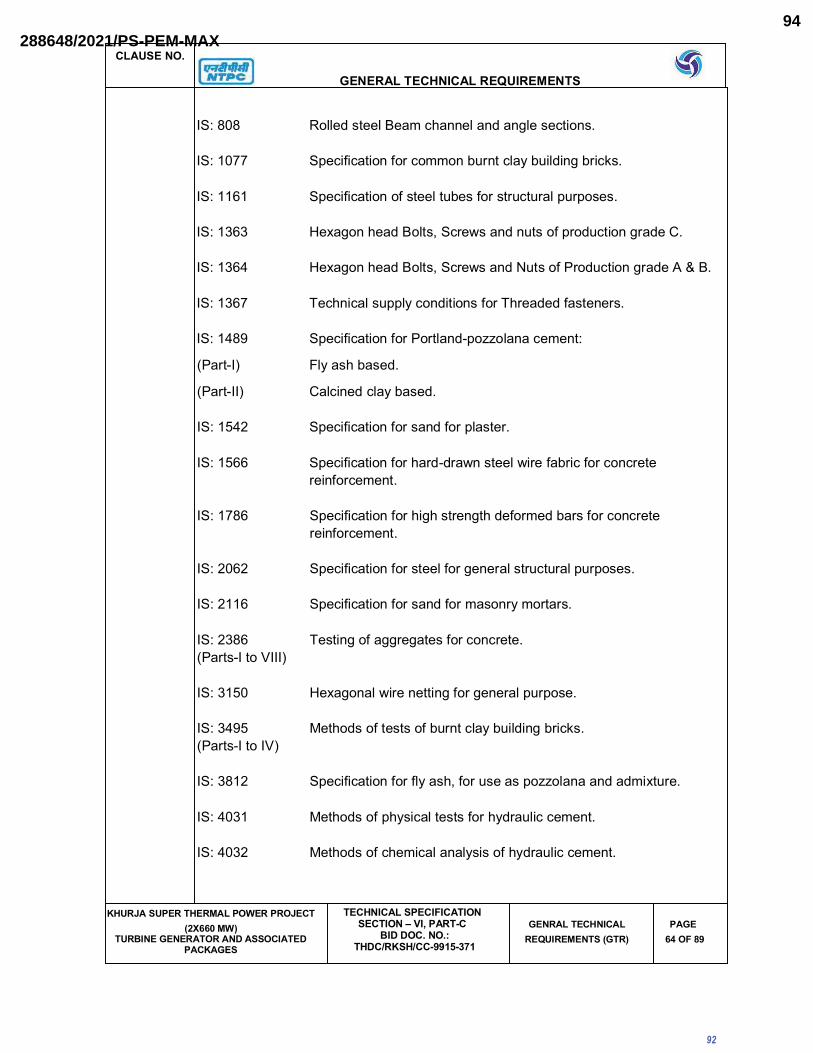
CLAUSE NO.
GENERAL TECHNICAL REQUIREMENTS
KHURJA SUPER THERMAL POWER PROJECT (2X660 MW)
TURBINE GENERATOR AND ASSOCIATED PACKAGES
TECHNICAL SPECIFICATIONSECTION – VI, PART-C
BID DOC. NO.: THDC/RKSH/CC-9915-371
GENRAL TECHNICAL REQUIREMENTS (GTR)
PAGE64 OF 89
IS: 808 Rolled steel Beam channel and angle sections.
IS: 1077 Specification for common burnt clay building bricks.
IS: 1161 Specification of steel tubes for structural purposes.
IS: 1363 Hexagon head Bolts, Screws and nuts of production grade C.
IS: 1364 Hexagon head Bolts, Screws and Nuts of Production grade A & B.
IS: 1367 Technical supply conditions for Threaded fasteners.
IS: 1489 Specification for Portland-pozzolana cement:
(Part-I) Fly ash based.
(Part-II) Calcined clay based.
IS: 1542 Specification for sand for plaster.
IS: 1566 Specification for hard-drawn steel wire fabric for concrete
reinforcement.
IS: 1786 Specification for high strength deformed bars for concrete
reinforcement.
IS: 2062 Specification for steel for general structural purposes.
IS: 2116 Specification for sand for masonry mortars.
IS: 2386 Testing of aggregates for concrete.
(Parts-I to VIII)
IS: 3150 Hexagonal wire netting for general purpose.
IS: 3495 Methods of tests of burnt clay building bricks.
(Parts-I to IV)
IS: 3812 Specification for fly ash, for use as pozzolana and admixture.
IS: 4031 Methods of physical tests for hydraulic cement.
IS: 4032 Methods of chemical analysis of hydraulic cement.
92
288648/2021/PS-PEM-MAX94

CLAUSE NO.
GENERAL TECHNICAL REQUIREMENTS
KHURJA SUPER THERMAL POWER PROJECT (2X660 MW)
TURBINE GENERATOR AND ASSOCIATED PACKAGES
TECHNICAL SPECIFICATIONSECTION – VI, PART-C
BID DOC. NO.: THDC/RKSH/CC-9915-371
GENRAL TECHNICAL REQUIREMENTS (GTR)
PAGE65 OF 89
IS: 4082 Recommendations on stacking and storage of construction
materials at site.
IS: 8112 Specification for 43 grade ordinary portland cement.
IS: 8500 Medium and high strength structural steel.
IS: 12269 53 grade ordinary portland cement.
IS: 12894 Specification for Fly ash lime bricks.
Cast-In-Situ Concrete and Allied Works
IS: 280 Specification for mild steel wire for general engineering purposes.
IS: 456 Code of practice for plain and reinforced concrete.
IS: 457 Code of practice for general construction of plain & reinforced
concrete for dams & other massive structures.
IS: 516 Method of test for strength of concrete.
IS: 650 Specification for standard sand for testing of cement.
IS: 1199 Methods of sampling and analysis of concrete.
IS: 1791 General requirements for batch type concrete mixers.
IS: 1838 Specification for preformed fillers for expansion joints in
(Part-I) concrete pavements and structures (non-extruding and resilient
type).
IS: 2204 Code of practice for construction of reinforced concrete shell roof.
IS: 2210 Criteria for the design of reinforced concrete shell structures and
folded plates.
IS: 2438 Specification for roller pan mixer.
IS: 2502 Code of practice for bending and fixing of bars for concrete
reinforcement.
IS: 2505 General requirements for concrete vibrators, immersion type.
93
288648/2021/PS-PEM-MAX95

CLAUSE NO.
GENERAL TECHNICAL REQUIREMENTS
KHURJA SUPER THERMAL POWER PROJECT (2X660 MW)
TURBINE GENERATOR AND ASSOCIATED PACKAGES
TECHNICAL SPECIFICATIONSECTION – VI, PART-C
BID DOC. NO.: THDC/RKSH/CC-9915-371
GENRAL TECHNICAL REQUIREMENTS (GTR)
PAGE66 OF 89
IS: 2506 General requirements for concrete vibrators, screed board type.
IS: 2514 Specification for concrete vibrating tables.
IS: 2645 Specification for Integral cement water proofing compounds.
IS: 2722 Specification for portable swing weigh batches for concrete.
(single and double bucket type)
IS: 2750 Specification for Steel scaffolding.
IS: 2751 Code of practice for welding of mild steel plain and deformed bars
for reinforced concrete construction.
IS: 3025 Methods of sampling and test waste water.
IS: 3366 Specification for Pan vibrators.
IS: 3370 Code of practice for concrete structures for the storage of
(Part I to IV) liquids.
IS: 3414 Code of practice for design and installation of joints in buildings.
IS: 3550 Methods of test for routine control for water used in industry.
IS: 3558 Code of practice for use of immersion vibrators for consolidating
concrete.
IS: 4014 Code of practice for steel tubular scaffolding.
(Parts I & II)
IS: 4326 Code of practice for earthquake resistant design and construction
of buildings.
IS: 4461 Code of practice for joints in surface hydro-electric power stations.
IS: 4656 Specification for form vibrators for concrete.
IS: 4925 Specification for batching and mixing plant.
IS: 4990 Specification for plywood for concrete shuttering work.
94
288648/2021/PS-PEM-MAX96
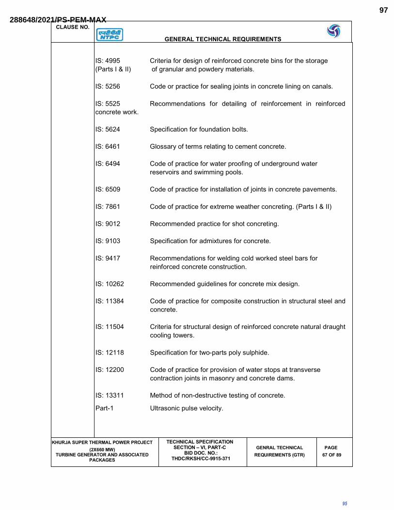
CLAUSE NO.
GENERAL TECHNICAL REQUIREMENTS
KHURJA SUPER THERMAL POWER PROJECT (2X660 MW)
TURBINE GENERATOR AND ASSOCIATED PACKAGES
TECHNICAL SPECIFICATIONSECTION – VI, PART-C
BID DOC. NO.: THDC/RKSH/CC-9915-371
GENRAL TECHNICAL REQUIREMENTS (GTR)
PAGE67 OF 89
IS: 4995 Criteria for design of reinforced concrete bins for the storage
(Parts I & II) of granular and powdery materials.
IS: 5256 Code or practice for sealing joints in concrete lining on canals.
IS: 5525 Recommendations for detailing of reinforcement in reinforced
concrete work.
IS: 5624 Specification for foundation bolts.
IS: 6461 Glossary of terms relating to cement concrete.
IS: 6494 Code of practice for water proofing of underground water
reservoirs and swimming pools.
IS: 6509 Code of practice for installation of joints in concrete pavements.
IS: 7861 Code of practice for extreme weather concreting. (Parts I & II)
IS: 9012 Recommended practice for shot concreting.
IS: 9103 Specification for admixtures for concrete.
IS: 9417 Recommendations for welding cold worked steel bars for
reinforced concrete construction.
IS: 10262 Recommended guidelines for concrete mix design.
IS: 11384 Code of practice for composite construction in structural steel and
concrete.
IS: 11504 Criteria for structural design of reinforced concrete natural draught
cooling towers.
IS: 12118 Specification for two-parts poly sulphide.
IS: 12200 Code of practice for provision of water stops at transverse
contraction joints in masonry and concrete dams.
IS: 13311 Method of non-destructive testing of concrete.
Part-1 Ultrasonic pulse velocity.
95
288648/2021/PS-PEM-MAX97

CLAUSE NO.
GENERAL TECHNICAL REQUIREMENTS
KHURJA SUPER THERMAL POWER PROJECT (2X660 MW)
TURBINE GENERATOR AND ASSOCIATED PACKAGES
TECHNICAL SPECIFICATIONSECTION – VI, PART-C
BID DOC. NO.: THDC/RKSH/CC-9915-371
GENRAL TECHNICAL REQUIREMENTS (GTR)
PAGE68 OF 89
Part-2 Rebound hammer.
SP:23 Handbook of concrete mixes
SP: 24 Explanatory Handbook on IS: 456-1978
SP: 34 Handbook on concrete reinforcement and detailing.
Precast Concrete Works
SP: 7(PartVI/ National Building Code- Structural design of
prefabrication and Sec.7) systems building.
IS: 10297 Code of practice for design and construction of floors and roofs
using precast reinforced/prestressed concrete ribbed or cored
slab units.
IS: 10505 Code of practice for construction of floors and roofs using pre-cast
reinforced concrete units.
Masonary and Allied Works
IS: 1905 Code of Practice for Structural Safety of Buildings-Masonry walls.
IS: 2212 Code of Practice for Brickwork.
IS: 2250 Code of Practice for Preparation and use of Masonry Mortar.
SP: 20 Explanatory hand book on masonry code.
Sheeting Works
IS:277 Galvanised steel sheets (plain or corrugated).
IS: 459 Unreinforced corrugated and semi-corrugated asbestos cement
sheets.
IS: 513 Cold-rolled carbon steel sheets.
IS: 730 Specification for fixing accessories for corrugated sheet
roofing.
96
288648/2021/PS-PEM-MAX98

CLAUSE NO.
GENERAL TECHNICAL REQUIREMENTS
KHURJA SUPER THERMAL POWER PROJECT (2X660 MW)
TURBINE GENERATOR AND ASSOCIATED PACKAGES
TECHNICAL SPECIFICATIONSECTION – VI, PART-C
BID DOC. NO.: THDC/RKSH/CC-9915-371
GENRAL TECHNICAL REQUIREMENTS (GTR)
PAGE69 OF 89
IS: 1626 Specification for Asbestos cement building pipes and pipe
fittings, gutters and gutter fittings and roofing fittings.
IS: 2527 Code of practice for fixing rain water gutters and down pipe for
roof drainage.
IS: 3007 Code of practice for laying of asbestos cement sheets.
IS: 5913 Methods of test for asbestos cement products.
IS: 7178 Technical supply conditions for tapping screw.
IS: 8183 Bonded mineral wool.
IS: 8869 Washers for corrugated sheet roofing.
IS: 12093 Code of practice for laying and fixing of sloped roof covering using
plain and corrugated galvanised steel sheets.
IS: 12866 Plastic translucent sheets made from thermosetting polyster resin
(glass fibre reinforced).
IS: 14246 Specification for continuously pre-painted galvanised steel sheets
and coils.
Fabrication and Erection of Structural Steel Work
IS: 2016 Specification for plain washers.
IS: 814 Specification for covered Electrodes for Metal Arc Welding for
weld steel.
IS: 1852 Specification for Rolling and Cutting Tolerances for Hot rolled
steel products.
IS: 3502 Specifications for chequered plate.
IS: 6911 Specification for stainless steel plate, sheet and strip.
IS: 3757 Specification for high strength structural bolts
IS: 6623 Specification for high strength structural nuts.
97
288648/2021/PS-PEM-MAX99

CLAUSE NO.
GENERAL TECHNICAL REQUIREMENTS
KHURJA SUPER THERMAL POWER PROJECT (2X660 MW)
TURBINE GENERATOR AND ASSOCIATED PACKAGES
TECHNICAL SPECIFICATIONSECTION – VI, PART-C
BID DOC. NO.: THDC/RKSH/CC-9915-371
GENRAL TECHNICAL REQUIREMENTS (GTR)
PAGE70 OF 89
IS: 6649 High Tensile friction grip washers.
IS: 800 Code of practice for use of structural steel in general building
construction.
IS: 816 Code of practice for use of Metal Arc Welding for General
Construction.
IS: 4000 Code of practice for assembly of structural joints using high
tensile friction grip fasteners.
IS: 9595 Code of procedure of Manual Metal Arc Welding of Mild Steel.
IS: 817 Code of practice for Training and Testing of Metal Arc Welders.
IS: 1811 Qualifying tests for Metal Arc Welders (engaged in welding
structures other than pipes).
IS: 9178 Criteria for Design of steel bins for storage of Bulk Materials.
IS: 9006 Recommended Practice for Welding of Clad Steel.
IS: 7215 Tolerances for fabrication steel structures.
IS: 12843 Tolerance for erection of structural steel.
IS: 4353 Recommendations for submerged arc welding of mild steel and
low alloy steels.
SP: 6 ISI Hand book for structural Engineers.
(Part 1 to 7)
IS: 1608 Method of Tensile Testing of Steel products other than sheets,
strip, wire and tube.
IS: 1599 Method of Bend Tests for Steel products other than sheet, strip,
wire and tube
IS : 228 Methods of chemical Analysis of pig iron, cast iron and plain
carbon and low alloy steel.
IS : 2595 Code of Practice for Radio graphic testing.
98
288648/2021/PS-PEM-MAX100

CLAUSE NO.
GENERAL TECHNICAL REQUIREMENTS
KHURJA SUPER THERMAL POWER PROJECT (2X660 MW)
TURBINE GENERATOR AND ASSOCIATED PACKAGES
TECHNICAL SPECIFICATIONSECTION – VI, PART-C
BID DOC. NO.: THDC/RKSH/CC-9915-371
GENRAL TECHNICAL REQUIREMENTS (GTR)
PAGE71 OF 89
IS : 1182 Recommended practice for Radiographic Examination of fusion
welded butt joints in steel plates.
IS : 3664 Code of practice for Ultra sonic Testing by pulse echo method.
IS : 3613 Acceptance tests for wire flux combination for submerged Arc
Welding.
IS : 3658 Code of practice for Liquid penetrant Flaw Detection.
IS : 5334 Code of practice for Magnetic Particle Flaw Detection of Welds.
Plastering and Allied Works
IS : 1635 Code of practice for field slaking of Building lime and preparation
of putty.
IS : 1661 Application of cement and cement lime plaster finishes.
IS : 2333 Plaster-of-paris.
IS : 2402 Code of practice for external rendered finishes.
IS : 2547 Gypsum building plaster.
IS : 3150 Hexagonal wire netting for general purpose.
Acid and Alkali Resistant Lining
IS : 158 Ready mixed paint, brushing, bituminous, black, lead free, acid,
alkali & heat resisting.
IS : 412 Specification for expanded metal steel sheets for general
purpose.
IS : 4441 Code of practice for use of silicate type chemical resistant
mortars.
IS : 4443 Code of practice for use of resin type chemical resistant
mortars.
IS : 4456 Method of test for chemical resistant tiles.
(Part I & II)
99
288648/2021/PS-PEM-MAX101

CLAUSE NO.
GENERAL TECHNICAL REQUIREMENTS
KHURJA SUPER THERMAL POWER PROJECT (2X660 MW)
TURBINE GENERATOR AND ASSOCIATED PACKAGES
TECHNICAL SPECIFICATIONSECTION – VI, PART-C
BID DOC. NO.: THDC/RKSH/CC-9915-371
GENRAL TECHNICAL REQUIREMENTS (GTR)
PAGE72 OF 89
IS : 4457 Specification for ceramic unglazed vitreous acid resistant tiles.
IS : 4832 Specification for chemical resistant mortars.
Part I Silicate type
Part II Resin type
Part III Sulphur type
IS : 4860 Specification for acid resistant bricks.
IS : 9510 Specification for bitumasitc, Acid resisting grade.
Water Supply, Drainage and Sanitation
IS : 458 Specification for concrete pipes.
IS : 554 Dimensions for pipe threads, where pressure tight joints are made
on thread.
IS : 651 Specification for salt glazed stoneware pipes.
IS : 774 Flushing cisterns for water closets and urinals.
IS : 775 Cast iron brackets and supports for wash basins and sinks.
IS : 778 Copper alloy gate, globe and check valves for water works
purposes.
IS : 781 Cast copper alloy screw down bib taps and stop valves for water
services.
IS : 782 Caulking lead.
IS : 783 Code of practice for laying of concrete pipes.
IS : 1172 Basic requirements for water supply, drainage and sanitation.
IS : 1230 Cast iron rain water pipes and fittings.
IS : 1239 Mild steel tubes, tubulars and other wrought steel fittings.
100
288648/2021/PS-PEM-MAX102

CLAUSE NO.
GENERAL TECHNICAL REQUIREMENTS
KHURJA SUPER THERMAL POWER PROJECT (2X660 MW)
TURBINE GENERATOR AND ASSOCIATED PACKAGES
TECHNICAL SPECIFICATIONSECTION – VI, PART-C
BID DOC. NO.: THDC/RKSH/CC-9915-371
GENRAL TECHNICAL REQUIREMENTS (GTR)
PAGE73 OF 89
IS : 1536 Centrifugally cast (Spun) iron pressure pipes for water, gas and
sewage.
IS : 1537 Vertically cast iron pressure pipes for water, gas and sewage.
IS : 1538 Cast iron fittings for pressure pipe for water, gas and sewage.
IS : 1703 Ball valves (horizontal plunger type) including float for water
supply purposes.
IS : 1726 Cast iron manhole covers and frames.
IS : 1729 Sand cast iron spigot and socket, soil, water and ventilating pipes,
fittings and accessories.
IS : 1742 Code of practice for building drainage.
IS : 1795 Pillar taps for water supply purposes.
IS : 1879 Malleable cast iron pipe fittings.
IS : 2064 Code of practice for selection, installation and maintenance of
sanitary appliances.
IS : 2065 Code of practice for water supply in building.
IS : 2326 Automatic flushing cisterns for urinals.
IS : 2470 Code of practice for installation of septic tanks.
(Part-I & II)
IS : 2501 Copper tubes for general engineering purposes.
IS : 2548 Plastic seat and cover for water-closets.
IS : 2556 Vitreous sanitary appliances (vitreous china).
(Part 1 to 15)
IS : 2963 Non-ferrous waste fittings for wash basins and sinks.
IS : 3114 Code of practice for laying of cast iron pipes.
101
288648/2021/PS-PEM-MAX103

CLAUSE NO.
GENERAL TECHNICAL REQUIREMENTS
KHURJA SUPER THERMAL POWER PROJECT (2X660 MW)
TURBINE GENERATOR AND ASSOCIATED PACKAGES
TECHNICAL SPECIFICATIONSECTION – VI, PART-C
BID DOC. NO.: THDC/RKSH/CC-9915-371
GENRAL TECHNICAL REQUIREMENTS (GTR)
PAGE74 OF 89
IS : 3311 Waste plug and its accessories for sinks and wash basins.
IS : 3438 Silvered glass mirrors for general purposes.
IS : 3486 Cast iron spigot and socket drain pipes.
IS : 3589 Electrically welded steel pipes for water, gas and sewage
(200mm to 2000mm nominal diameter).
IS : 3989 Centrifugally cast (Spun) iron spigot and socket soil, waste and
ventilating pipes, fittings and accessories.
IS : 4111 Code of practice for ancillary structure in sewerage system.
(Part I to IV)
IS : 4127 Code of practice for laying of glazed stone-ware pipes.
IS : 4764 Tolerance limits for sewage effluents discharged into inland-
surface waters.
IS : 4827 Electro plated coating of nickel and chromium on copper and
copper alloys.
IS : 5329 Code of practice for sanitary pipe work above ground for
buildings.
IS : 5382 Rubber sealing rings for gas mains, water mains and sewers.
IS : 5822 Code of practice for laying of welded steel pipes for water
supply.
IS : 5961 Cast iron grating for drainage purpose.
IS : 7740 Code of practice for road gullies.
IS : 8931 Cast copper alloy fancy bib taps and stop valves for water
services.
IS : 8934 Cast copper alloy fancy pillar taps for water services.
IS : 9762 Polyethylene floats for ball valves.
102
288648/2021/PS-PEM-MAX104

CLAUSE NO.
GENERAL TECHNICAL REQUIREMENTS
KHURJA SUPER THERMAL POWER PROJECT (2X660 MW)
TURBINE GENERATOR AND ASSOCIATED PACKAGES
TECHNICAL SPECIFICATIONSECTION – VI, PART-C
BID DOC. NO.: THDC/RKSH/CC-9915-371
GENRAL TECHNICAL REQUIREMENTS (GTR)
PAGE75 OF 89
IS : 10446 Glossary of terms for water supply and sanitation.
IS : 10592 Industrial emergency showers, eye and face fountains and
combination units.
IS : 12592 Specification for precast concrete manhole covers and frames.
IS : 12701 Rotational moulded polyethylene water storage tanks.
SP: 35 Hand book on water supply and drainage.
- Manual on Sewerage and sewage treatment (Published by CPH &
EEO) As updated.
Doors, Windows and Allied Works
IS : 204 Tower Bolts
Part-I Ferrous metals.
Part-II Nonferrous metals.
IS : 208 Door Handles.
IS : 281 Mild steel sliding door bolts for use with padlocks.
IS : 362 Parliament Hinges.
IS : 420 Specification for putty, for use on metal frames.
IS : 1003 Specification for timber panelled and glazed shutters-
Part-I door (Part-I) shutters.
IS : 1038 Steel doors, windows and ventilators.
IS : 1081 Code of practice for fixing and glazing of metal (steel and
aluminium) doors, windows and ventilators.
IS : 1341 Steel butt hinges.
IS : 1361 Steel windows for industrial buildings.
IS : 1823 Floor door stoppers.
103
288648/2021/PS-PEM-MAX105

CLAUSE NO.
GENERAL TECHNICAL REQUIREMENTS
KHURJA SUPER THERMAL POWER PROJECT (2X660 MW)
TURBINE GENERATOR AND ASSOCIATED PACKAGES
TECHNICAL SPECIFICATIONSECTION – VI, PART-C
BID DOC. NO.: THDC/RKSH/CC-9915-371
GENRAL TECHNICAL REQUIREMENTS (GTR)
PAGE76 OF 89
IS : 1868 Anodic coatings on Aluminium and its alloys.
IS : 2202 Specification for wooden flush door shutters (solid core type);
(Part-II) particle board face panels and hard board face panels
IS:2209 Mortice locks (vertical type).
IS:2553 Safety glass
IS:2835 Flat transparent sheet glass.
IS:3548 Code of practice for glazing in buildings.
IS:3564 Door closers (Hydraulically regulated).
IS : 3614 Fire check doors; plate, metal covered and rolling type.
IS:4351 Steel door frames.
IS:5187 Flush bolts.
IS:5437 Wired and figured glass
IS:6248 Metal rolling shutters and rolling grills.
IS:6315 Floor springs (hydraulically regulated) for heavy doors.
IS:7196 Hold fasts.
IS:7452 Hot rolled steel sections for doors, windows and ventilators.
IS:10019 Mild steel stays and fasteners.
IS:10451 Steel sliding shutters (top hung type).
IS:10521 Collapsible gates.
Roof Water Proofing and AlliedWorks
IS:1203 Methods of testing tar and bitumen.
104
288648/2021/PS-PEM-MAX106

CLAUSE NO.
GENERAL TECHNICAL REQUIREMENTS
KHURJA SUPER THERMAL POWER PROJECT (2X660 MW)
TURBINE GENERATOR AND ASSOCIATED PACKAGES
TECHNICAL SPECIFICATIONSECTION – VI, PART-C
BID DOC. NO.: THDC/RKSH/CC-9915-371
GENRAL TECHNICAL REQUIREMENTS (GTR)
PAGE77 OF 89
IS:1322 Specification for bitumen felts for water proofing and damp
proofing.
IS:1346 Code of practice for water proofing of roofs with bitumen felts.
IS:1580 Specification for bituminous compound for water proofing and
caulking purposes.
IS:3067 Code of practice for general design details and preparatory work
for damp proofing and water proofing of buildings.
IS:3384 Specification for bitumen primer for use in water proofing and
damp proofing.
Floor Finishes and Allied Works
IS:1237 Specification for cement concrete flooring tiles.
IS:1443 Code of practice for laying and finishing of cement concrete
flooring tiles.
IS:2114 Code of practice for laying in-situ terrazzo floor finish.
IS:2571 Code of practice for laying in-situ cement concrete flooring.
IS:3462 Specification for unbacked flexible PVC flooring.
IS:4971 Recommendations for selection of industrial floor finishes.
IS:5318 Code of practice for laying of flexible PVC sheet and tile
flooring.
IS:8042 Specification for white portland cement.
IS:13801 Specification for chequered cement concrete flooring tiles.
Painting and Allied Works
IS:162 Specification for fire resisting silicate type, brushing, for use on
wood, colour as required.
IS:1477 Code of practice for painting of ferrous metals in buildings.
Part-I Pretreatment.
105
288648/2021/PS-PEM-MAX107

CLAUSE NO.
GENERAL TECHNICAL REQUIREMENTS
KHURJA SUPER THERMAL POWER PROJECT (2X660 MW)
TURBINE GENERATOR AND ASSOCIATED PACKAGES
TECHNICAL SPECIFICATIONSECTION – VI, PART-C
BID DOC. NO.: THDC/RKSH/CC-9915-371
GENRAL TECHNICAL REQUIREMENTS (GTR)
PAGE78 OF 89
Part-II Painting.
IS:1650 Specification for colours for building and decorative finishes.
IS:2074 Specification for red oxide-zinc chrome, priming, ready mixed
paint air drying.
IS:2338 Code of practice for finishing of wood and wood based
materials.
Part-I Operations and workmanship
Part-II Schedules
IS:2395 Code of practice for painting concrete, masonry and plaster
surfaces.
Part-I Operations and workmanship.
Part-II Schedule.
IS:2524 Code of practice for painting of nonferrous metals in buildings.
Part-I Pretreatment.
Part-II Painting.
IS:2932 Specification of synthetic enamel paint, exterior, under-coating
and finishing.
IS:2933 Specification enamel paint, under coating and finishing.
IS:4759 Code of practice for hot dip zinc coating on structural steel and
other allied products.
IS:5410 Specification for cement paint
IS:5411 Specification for plastic emulsion paint-for exterior use
(Part-I)
IS:6278 Code of practices for white washing and colour washing.
IS:10403 Glossary of terms relating to building finishes.
Piling and Foundation
IS:1080 Code of practice for design and construction of simple spread
foundations.
106
288648/2021/PS-PEM-MAX108

CLAUSE NO.
GENERAL TECHNICAL REQUIREMENTS
KHURJA SUPER THERMAL POWER PROJECT (2X660 MW)
TURBINE GENERATOR AND ASSOCIATED PACKAGES
TECHNICAL SPECIFICATIONSECTION – VI, PART-C
BID DOC. NO.: THDC/RKSH/CC-9915-371
GENRAL TECHNICAL REQUIREMENTS (GTR)
PAGE79 OF 89
IS:1904 Code of practice for design and construction of foundations in
Soils; General Requirements.
IS:2911 Code of practice for designs and construction of Pile
foundations (Relevant Parts).
IS:2950 Code of practice for designs and construction of Raft
(Part-I) foundation.
IS:2974 Code of practice for design and construction of machine
(Part-I TO V) foundations.
IS:6403 Code of practice for determination of Allowable Bearing
pressure on Shallow foundation.
IS:8009 Code of practice for calculation of settlement of foundation
subjected to symmetrical vertical loads.
Part-I Shallow foundations.
Part-II Deep foundations.
IS:12070 Code of practice for design and construction of shallow
foundations on rocks.
DIN:4024 Flexible supporting structures for machines with rotating
machines.
VDI:2056 Criteria for assessing mechanical vibrations of machines.
VDI:2060 Criteria for assessing rotating imbalances in machines.
Stop Log and Trash Rack
IS:4622 Recommendations for fixed - wheel gates structural design.
IS:5620 Recommendations for structural design criteria for low head slide
gates.
IS:11388 Recommendations for design of trash rack for intakes.
IS:11855 General requirements for rubber seals for hydraulic gates.
Roads
IRC:5 Standard specifications and Code of practice for road bridges,
section-I general Features of Design.
IRC:14 Recommended practice of 2cm thick bitumen and tar carpets.
IRC:16 Specification for priming of base course with bituminous
primers.
107
288648/2021/PS-PEM-MAX109

CLAUSE NO.
GENERAL TECHNICAL REQUIREMENTS
KHURJA SUPER THERMAL POWER PROJECT (2X660 MW)
TURBINE GENERATOR AND ASSOCIATED PACKAGES
TECHNICAL SPECIFICATIONSECTION – VI, PART-C
BID DOC. NO.: THDC/RKSH/CC-9915-371
GENRAL TECHNICAL REQUIREMENTS (GTR)
PAGE80 OF 89
IRC:19 Standard specifications and code of practice for water bound
macadam.
IRC:21 Standard specifications and Code of practice for road bridges,
section-III - Cement concrete (plain and reinforced).
IRC:34 Recommendations for road construction in waterlogged areas.
IRC:36 Recommended practice for the construction of earth
embankments for road works.
IRC:37 Guidelines for the Design of flexible pavements.
IRC:56 Recommended practice for treatment of embankment slopes for
erosion control.
IRC:73 Geometric design standards for rural (non-urban) highways.
IRC:86 Geometric Design standards for urban roads in plains.
IRC:SP:13 Guidelines for the design of small bridges & culverts.
IRC - Public- Ministry of Surface Transport (Roads Wing), Specifications
ation for road and bridge works.
IS:73 Specification for paving bitumen
Loadings
IS:875 Code of practice for design loads other than earthquake) for
(Pt. I to V) buildings and structures.
IS:1893 Criteria for earthquake resistant design of structures.
IS:4091 Code of Practice for design and construction of foundation for
transmission line towers & poles.
IRC:6 Standard specifications & code of practice for road bridges,
Section-II Loads and stresses.
M.O.T. Deptt. of railways Bridge Rules.
Safety
IS:3696 Safety code for scaffolds and ladders.
(Part I & II)
IS:3764 Safety code for excavation work.
IS:4081 Safety code for blasting and related drilling operations.
IS:4130 Safety code for demolition of buildings.
108
288648/2021/PS-PEM-MAX110

CLAUSE NO.
GENERAL TECHNICAL REQUIREMENTS
KHURJA SUPER THERMAL POWER PROJECT (2X660 MW)
TURBINE GENERATOR AND ASSOCIATED PACKAGES
TECHNICAL SPECIFICATIONSECTION – VI, PART-C
BID DOC. NO.: THDC/RKSH/CC-9915-371
GENRAL TECHNICAL REQUIREMENTS (GTR)
PAGE81 OF 89
IS:5121 Safety code for piling and other deep foundations.
IS:5916 Safety code for construction involving use of hot bituminous
materials.
IS:7205 Safety code for erection on structural steelwork.
IS:7293 Safety code for working with construction machinery.
IS:7969 Safety code for handling and storage of building materials
IS:11769 Guidelines for safe use of products containing asbestos.
- Indian Explosives Act. 1940 as updated.
Architectural design of buildings
SP:7 National Building Code of India
SP:41 Hand book on functional requirements of buildings (other than
industrial buildings)
Miscellaneous
IS:802 Code of practice for use of structural steel in
(Relevant parts) overhead transmission line towers.
IS:803 Code of practice for design, fabrication and erection of vertical
mild steel cylindrically welded in storage tanks.
IS:10430 Creteria for design of lined canals and liner for selection of type of
lining.
IS:11592 Code of practice for selection and design of belt conveyors.
IS:12867 PVC handrails covers.
CIRIA Design and construction of buried thin-wall pipes.
Publication
REFERENCE CODES AND STANDARDS FOR CONTROL AND INSTRUMENTATION
The design, manufacture, inspection, testing & installation of all equipment and
system covered under this specification shall conform to the latest editions of codes
and standards mentioned below and all other applicable VDE, IEEE, ANSI, ASME,
NEC, NEMA, ISA AND Indian Standards and their equivalents.
109
288648/2021/PS-PEM-MAX111

CLAUSE NO.
GENERAL TECHNICAL REQUIREMENTS
KHURJA SUPER THERMAL POWER PROJECT (2X660 MW)
TURBINE GENERATOR AND ASSOCIATED PACKAGES
TECHNICAL SPECIFICATIONSECTION – VI, PART-C
BID DOC. NO.: THDC/RKSH/CC-9915-371
GENRAL TECHNICAL REQUIREMENTS (GTR)
PAGE82 OF 89
Temperature Measurements
1. Instrument and apparatus for temperature measurement - ASME PTC 19.3
(1974).
2. Temperature measurement - Thermocouples ANSI MC 96.1 - 1982.
3. Temperature measuremnet by electrical Resistance thermometers - IS:2806.
4. Thermometer - element - Platinum resistance - IS:2848.
Pressure Measurements
1. a) Instruments and apparatus for pressure measurement - ASME PTC
19.2 (1964).
b) Electonic transmitters BS:6447.
2. Bourdon tube pressure and vacuum gauges - IS:3624 - 1966.
3. Process operated switch devices (Pr. Switch) BS-6134.
Flow Measurements
Instruments and apparatus for flow measurements - ASME PTC 19.5 (1972) Interim
supplement, Part-II.
Measurement of fluid flow in closed conduits - BS-1042.
Electronic Measuring Instrument & Control Hardware/ Software
1. Automatic null balancing electrical measuring instruments - ANSI C 39.4
(Rev. 1973): IS:9319.
2. Safety requirements for electrical and electronic measuring and controling
instrument - ANSI C 39.5 - 1974.
3. Compatability of analog signals for electronic industrial process instruments -
ISA - S 50.1 (1982) ANSI MC 12.1 - 1975.
4. Dynamic response testing of process control instrumentation ISA - S 26
(1968).
5. Surge Withstand Capability (SWC) tests - ANSI C 37.90 a/IEEE-472 or
suitable class of IEC-255-4 equivalent to ANSI C37.90a/IEEE-472.
6. Printed circuit boards - IPC TM - 650, IEC 326 C.
110
288648/2021/PS-PEM-MAX112

CLAUSE NO.
GENERAL TECHNICAL REQUIREMENTS
KHURJA SUPER THERMAL POWER PROJECT (2X660 MW)
TURBINE GENERATOR AND ASSOCIATED PACKAGES
TECHNICAL SPECIFICATIONSECTION – VI, PART-C
BID DOC. NO.: THDC/RKSH/CC-9915-371
GENRAL TECHNICAL REQUIREMENTS (GTR)
PAGE83 OF 89
7. General requirement and tests for printed wiring boards - IS 7405 (Part-I)
1973.
8. Edge socket connectors - IEC 130-11.
9. Requirements and methods of testing of wire wrap terminations DIN 41611
Part-2.
10. Dimensions of attachment plugs & receptacles - ANSI C 73 - 1973
(Supplement ANSI C 73 a - 1980).
11. Direct acting electrical indicating instrument - IS:1248 - 1968 (R).
12. Standard Digital Interface for Programmable Instrumentation - IEEE-488.2 -
1990.
13. Information Processing Systems - Local Area Networks - Part 2 : Logical Link
Control - IEEE-802.2 - 1989.
14. Standard for Local Area Networks : Carrier Sense Multiple Access with
Collision Detection - IEEE-802.3 - 1985.
15. Supplements A, B, C and E to Carrier Sense Multiple Access with Collision
Detection - IEEE-802.3 - 1988.
16. Standard for Local Area Networks : Token - Passing Bus Access Method -
IEEE-802.4 - 1985.
17. Standard for Local Area Networks : Token - Ring Access Method and
Physical Layer Specification - IEEE-802.5 - 1985.
18. IEEE Guide to Software Requirements Specifications - IEEE-830 - 1984.
19. Hardware Testing of Digital Process Computers - ISA RP55.1 - 1983.
20. Electromagnetic Susceptibility of Process Control Instrumentation - SAMA
PMC 33.1 - 1978.
21. Interface Between the Data Terminal Equipment and Data Circuit -
Terminating Equipment Employing Serial Binary Data Interchange - EIA-232-
D-1987.
22. Electromagnetic Compatibility for Industrial Process Measurement and
Control Equipment, Part 3 : Radiated Electromagnetic Field Requirements -
IEC 801-3-1984.
Instrument Switches and Contact
111
288648/2021/PS-PEM-MAX113

CLAUSE NO.
GENERAL TECHNICAL REQUIREMENTS
KHURJA SUPER THERMAL POWER PROJECT (2X660 MW)
TURBINE GENERATOR AND ASSOCIATED PACKAGES
TECHNICAL SPECIFICATIONSECTION – VI, PART-C
BID DOC. NO.: THDC/RKSH/CC-9915-371
GENRAL TECHNICAL REQUIREMENTS (GTR)
PAGE84 OF 89
1. Contact rating - AC services NEMA ICS 2 - 1978 (with revision through May
1983), Part - 2-125, A6000.
2. Contact rating - DC services NEMA ICS 2-1978 Part-2 125, N600.
Enclosures
1. Type of Enclosures - NEMA ICS Part - 6 - 1978 (with Rev. 1 4/80) through
110.22 (Type 4 to 13).
2. Racks, panels and associated equipment - EIA : RS - 310 C- 1983 (ANSI C
83.9 - 1972).
3. Protection class for Enclosures, cabinets, control panels & desks - IS:2147 -
1962.
Apparatus, enclosures and installation practices in hazardous area
1. Classification of hazardous area - NFPA 70 - 1984, Article 500.
2. Electrical Instruments in hazardous dust location - ISA - 512.11, 1973.
3. Instrinsically safe apparatus - NFPA 493 1978.
4. Purged and pressurised enclosure for electrical equipment in hazardous
location - NFPA 496-1982.
5. Enclosures for Industrial Controls and Systems - NEMA IS 1.1 - 1977.
Sampling System
1. Stainless steel material of tubing and valves for sampling system - ASTMA
296-82, Grade 7 P 316.
2. Submerged helical coil heat exchangers for sample coolers ASTM D11 92-
1977.
3. Water and steam in power cycle - ASME PTC 19.11.
4. Standard methods of sampling system - ASTM D 1066-99.
Annunciators
1. Specifications and guides for the use of general purpose annunciators - ISA
S 19.1, 1979.
2. Surge withstand capability tests - ANSI C 37.90a - 1989/IEEE-472 or suitable
class of IEC 255-4 equivalent to ANSI C37.90a 1989/IEEE-472
112
288648/2021/PS-PEM-MAX114

CLAUSE NO.
GENERAL TECHNICAL REQUIREMENTS
KHURJA SUPER THERMAL POWER PROJECT (2X660 MW)
TURBINE GENERATOR AND ASSOCIATED PACKAGES
TECHNICAL SPECIFICATIONSECTION – VI, PART-C
BID DOC. NO.: THDC/RKSH/CC-9915-371
GENRAL TECHNICAL REQUIREMENTS (GTR)
PAGE85 OF 89
3. Damp heat cycling test - IS:2106
4. Specification for Electromagnetic Susceptibility - SAMA DMC 33, 1/78
Protections
1. Relays and relay system associated with electric power apparatus. ANSI C
37.90, 1 - 1989.
2. General requirements & tests for switching devices for control and auxiliary
circuits including contactor relays - IS:6875 (Part-I) - 1973.
3. Turbine water damage prevention - ASME TDP-1-1980.
4. Boiler safety interlocks - NFPA Section 85 B - 1984, 85 C - 1991.
UPS System
1. Practices and requirements for semi-conductor power rectifiers - ANSI C
34.2, 1973.
2. Relays and relays system associated with electrical power apparatus - ANSI
C 3.90 - 1983.
3. Surge withstand capability test - ANSI C 37.90 1 -1989.
4. Performance testing of UPS - IEC 146.
5. Stationary cells & Batteries Lead Acid type (with tubular positive plates)
specification IS-1651-1991.
6. Recommended practice for sizing large lead storage batteries for generating
stations & sub-stations - IEEE-485-1985.
7. Printed Circuit Board - IPC TM 650, IEC 326C.
8. General Requirements & tests for printed wiring boards, IS:7405 (Part-I)
1973.
Control Valves
1. Control valve sizing - Compressible & Incompressible fluids - ISA S 75.01-
1985.
2. Face to face dimensions of control valves - ANSI B 16.00 - 1973.
113
288648/2021/PS-PEM-MAX115

CLAUSE NO.
GENERAL TECHNICAL REQUIREMENTS
KHURJA SUPER THERMAL POWER PROJECT (2X660 MW)
TURBINE GENERATOR AND ASSOCIATED PACKAGES
TECHNICAL SPECIFICATIONSECTION – VI, PART-C
BID DOC. NO.: THDC/RKSH/CC-9915-371
GENRAL TECHNICAL REQUIREMENTS (GTR)
PAGE86 OF 89
3. ISA Hand Book of Control Valves - (ISBN : B: 1047-087664-234-2).
4. Codes for pressure piping - ANSI B 31.1
5. Control Valve leak class - ISA RP 39.6
Process Connection & Piping
1. Codes for pressure piping "power piping" - ANSI B 31.1.
2. Seamless carbon steel pipe ASTM - A - 106.
3. Forged & Rolled Alloy steel pipe flanges, forged fittings and valves and parts
- ASTM - A - 182.
4. Material for socket welded fittings - ASTM - A - 105.
5. Seamless ferritic alloy steep pipe - ASTM - A - 335.
6. Pipe fittings of wrought carbon steel and alloy steel - ASTM - A - 234.
7. Composition bronze of ounce metal castings - ASTM - B - 62.
8. Seamless Copper tube, bright annealed - ASTM - B - 168.
9. Seamless copper tube - ASTM - B - 75.
10. Dimension of fittings - ANSI - B - 16.11.
11. Valves flanged and butt welding ends - ANSI - B - 16.34.
Instrument Tubing
1. Seamless carbon steel pipe - ASTM - A 106.
2. Material of socketweld fittings - ASTM - A105.
3. Dimensions of fittings - ANSI - B - 16.11.
4. Code for pressure piping, welding, hydrostatic testing - ANSI B 31.1.
Cables
1. Thermocouples extension wires/cables - ANSI MC 96.1 - 1992.
2. Requirements for copper conductor-Wiring cables for telecommunications &
information processing system - VDE:0815.
114
288648/2021/PS-PEM-MAX116

CLAUSE NO.
GENERAL TECHNICAL REQUIREMENTS
KHURJA SUPER THERMAL POWER PROJECT (2X660 MW)
TURBINE GENERATOR AND ASSOCIATED PACKAGES
TECHNICAL SPECIFICATIONSECTION – VI, PART-C
BID DOC. NO.: THDC/RKSH/CC-9915-371
GENRAL TECHNICAL REQUIREMENTS (GTR)
PAGE87 OF 89
3. Colour coding of single or multi-pair cables - ICEA - S - 61-402 (third edition)
NEMA WCS - 1979 with revisions thorugh 2/83.
4. Insulation & Sheathing compounds for cables : VDE 0207 (Part-4, 5 & 6).
5. Guide design and installation of cable systems in power generating stations (
insulation, jacket materials) - IEEE Std. 422-1977.
6. Rules for Testing insulated cables and flexible cables : VVDE - 0472
7. Requirements of vertical flame propagation test - IEEE 383 - 1974 (R 1980)
8. Standard specification for tinned soft or annealed copper wire for electrical
purpose - ASTM B-33-81.
9. Oxygen index and temperature index test - ASTM D - 2863.
10. Smoke density measurement test - ASTMD - 2843.
11. Acid gas generation test - IEC - 754 - 1.
12. Swedish Chimney test - SEN - 4241475 (F3).
13. Teflon (FEP) insulation & sheath test - ASTMD - 2116.
14. Thermocouple compensating cables - Testing requirements & sampling plan
IS:8784.
15. PVC insulated electric cables for working voltage upto and including 1100 V -
IS:1554 (Part-I).
Cable Trays, Conduits
1. Guide for design and installation of cable systems in power generating
staiton (Cable trays, support systems, conduits) - IEEE Std. 422, 1977,
NEMA VE-1 1979, NFPA 70-1984.
2. -do- Test Standards. NEMA VE-1-1979.
3. Zinc coating "hot dip" on assembled products for galvanising of carbon steel
cable trays - ASTMA - 386-78.
Public Address System
1. Specifications for lod speakers - IS:7741 (Part-I, II and III)
2. Code of safety requirement for electric mains operated audio amplifiers -
IS:1301
115
288648/2021/PS-PEM-MAX117

CLAUSE NO.
GENERAL TECHNICAL REQUIREMENTS
KHURJA SUPER THERMAL POWER PROJECT (2X660 MW)
TURBINE GENERATOR AND ASSOCIATED PACKAGES
TECHNICAL SPECIFICATIONSECTION – VI, PART-C
BID DOC. NO.: THDC/RKSH/CC-9915-371
GENRAL TECHNICAL REQUIREMENTS (GTR)
PAGE88 OF 89
3. Specification for Public Address Amplifiers - IS:10426.
4. Code of practice for outdoor installation of PA system - IS:1982.
5. Code of practice for installation for indoor amplifying and sound distribution
system - IS:1881.
6. Basic environmental testing procedures for electronic and electrical items -
IS:9000.
7. Characteristics and methods of measurements for sound system equipment -
IS:9302
8. Code of practice of electrical wiring installations (System voltage not
exceeding 650 volts) - IS:732
9. Rigid steel conduits for electric wiring - IS:9537 (Part-I and II)
10. Fittings for rigid steel conduits for electrical wiring - IS:2667
11. Degree of protection provided by enclosure for low voltage switchgear and
control gear - IS:2147.
Vibration Monitoring System
1. API 670 - 1994
2. BS : 4675 Part-2
116
288648/2021/PS-PEM-MAX118

117
288648/2021/PS-PEM-MAX119

118
288648/2021/PS-PEM-MAX120
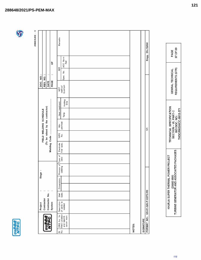
119
288648/2021/PS-PEM-MAX121

120
288648/2021/PS-PEM-MAX122

121
288648/2021/PS-PEM-MAX123

CLAUSE NO.MANDATORY SPARES
KHURJA SUPER THERMAL POWER PROJECT (2X660 MW)
TURBINE GENERATOR AND ASSOCIATED PACKAGES
TECHNICAL SPECIFICATIONSECTION-VI, PART-A
BID DOC NO.: THDC/RKSH/CC-9915-371
MANDATORY SPARESPAGE
1 OF 59
1.00.00 SPARES
The Bidder shall include in his scope of supply all the necessary Mandatory spares,
start up and commissioning spares and recommended spares and indicate these in
the relevant schedules of the Bid Form and Price Schedules. The general
requirements pertaining to the supply of these spares is given below:-
1.01.00 MANDATORY SPARES
(a) The list of mandatory spares considered essential by the Employer is
indicated in this chapter. The bidder shall indicate the prices for each and
every item (except for items not applicable to the bidders design) in the
'Schedule of mandatory Spares' whether or not he considers it necessary for
the Employer to have such spares. If the bidder fails to comply with the
above or fails to quote the price of any spare item, the cost of such spares
shall be deemed to be included in the contract price. The bidder shall furnish
the population per unit of each item in the Bid Forms and Price Schedules.
Whenever the quantity is mentioned in "sets" the bidder has to give the item
details and prices of each item.
(b) The Employer reserves the right to buy any or all the mandatory spares
parts.
(c) The prices of mandatory spares indicated by the Bidder in the Bid Proposal
sheets shall be used for bid evaluation purposes.
(d) All mandatory spares shall be delivered at site at least two months before
scheduled date of initial operation of the first unit. However, spares shall not
be dispatched before dispatch of corresponding main equipments.
(e) Wherever quantity is specified both as a percentage and a value, the Bidder
has to supply the higher quantity until and unless specified otherwise.
1.02.00 RECOMMENDED SPARES
(a) In addition to the spare parts mentioned above, the contractor shall also
provide a list of recommended spares for 3 years of normal operation of the
plant and indicate the list and total prices in relevant schedule of the Bid
Form and Price Schedules. This list shall take into consideration the
mandatory spares specified in this Section-VI, Part-A and should be
independent of the list of the mandatory spares. The Employer reserves the
right to buy any or all of the recommended spares. The recommended
spares shall be delivered at project site at least two months before the
122
Price Schedules
288648/2021/PS-PEM-MAX124

CLAUSE NO.MANDATORY SPARES
KHURJA SUPER THERMAL POWER PROJECT (2X660 MW)
TURBINE GENERATOR AND ASSOCIATED PACKAGES
TECHNICAL SPECIFICATIONSECTION-VI, PART-A
BID DOC NO.: THDC/RKSH/CC-9915-371
MANDATORY SPARESPAGE
2 OF 59
scheduled date of initial operation of first unit. However, the spares shall not
be dispatched before the dispatch of the main equipment.
(b) Price of recommended spars will not be used for evaluation of the bids. The
price of these spars will remain valid upto 6 months after placement of
Notification of Award for the main equipment. However, the Contractor shall
be liable to provide necessary justification for the quoted prices for these
spares as desired by the Employer.
1.03.00 START-UP & COMMISSIONING SPARES
Start-up and commissioning spares are those spares which may be required during
the start-up and commissioning of the equipment/system. All spares used till the
plant is handed over to the employer shall come under this category. The Contractor
shall provide for an adequate stock of such start up and commissioning spares to be
brought by him to the site for the plant erection and commissioning. They must be
available at site before the equipments are energized. The unused spares, if any,
should be removed from there only after the issue of Taking Over certificate. All
start up spares which remain unused at the time shall remain the property of the
Contractor.
1.04.00 The Bidder shall include in his scope of supply all the necessary Mandatory spares,
start up and commissioning spares and recommended spares and indicate these in
the relevant schedules of the Bid Form and Price Schedules. The general
requirements pertaining to the supply of these spars is given below.
2.00.00 The Contractor shall indicate the service expectancy period for the spares parts
(both mandatory and recommended) under normal operating conditions before
replacement is necessary.
3.00.00 All spares supplied under this contract shall be strictly inter changeable with the
parts for which they are intended for replacements. The spares shall be treated and
packed for long storage under the climatic conditions prevailing at the site e.g. small
items shall be packed in sealed transparent plastic with desecrator packs as
necessary.
4.00.00 All the spares (both recommended and mandatory) shall be manufactured alongwith
the main equipment components as a continuous operation as per same
specification and quality plan.
5.00.00 The contractor will provide Employer with cross-sectional drawings, catalogues,
assembly drawings and other relevant documents so as to enable the Employer to
identify and finalise order for recommended spares.
123
288648/2021/PS-PEM-MAX125

CLAUSE NO.MANDATORY SPARES
KHURJA SUPER THERMAL POWER PROJECT (2X660 MW)
TURBINE GENERATOR AND ASSOCIATED PACKAGES
TECHNICAL SPECIFICATIONSECTION-VI, PART-A
BID DOC NO.: THDC/RKSH/CC-9915-371
MANDATORY SPARESPAGE
3 OF 59
6.00.00 Each spares part shall be clearly marked or labelled on the outside of the packing
with its description. When more than one spares part is packed in a single case, a
general description of the content shall be shown on the outside of such case and a
detailed list enclosed. All cases, containers and other packages must be suitably
marked and numbered for the purposes of identification.
7.00.00 All cases, containers or other packages are to be opened for such examination as
may be considered necessary by the Employer.
8.00.00 The contractor will provide the Employer with all the addresses and particulars of his
sub suppliers while placing the order on vendors for items/components/equipments
covered under the contract and will further ensure with his vendors that the
Employer, if so desires, will have the right to place order for spares directly on them
on mutually agreed terms based on offers of such vendors.
9.00.00 The Contractor shall warrant that all spares supplied will be new and in accordance
with the contract Documents and will be free from defects in design, material and
workmanship.
10.00.00 In addition to the recommended spares listed by the contractor, if the employer
further identifies certain particular items of spares, the contractor shall submit the
prices and delivery quotation for such spares within 30 days of receipt of such
request with a validity period of 6 months for consideration by the Employer and
placement of order for additional spares if the Employer so desires.
11.00.00 The Contractor shall guarantee the long term availability of spares to the Employer
for the full life of the equipment covered under the contract. The Contractor shall
guarantee that before going out of production of spares parts of the equipment
covered under the Contract, he shall give the Employer atleast 2 years advance
notice so that the latter may order his bulk requirement of spares, if he so desires.
The same provision will also be applicable to sub-contractors. Further, in case of
discontinuance of manufacture of any spares by the Contractor and/or his sub
contractors, Contractor will provide the Employers, two years in advance, with full
manufacturing drawings, material specifications and technical information including
information on alternative equivalent makes required by the Employer for the
purpose of manufacture/procurement of such items.
12.00.00 Material Codification
The bidder to provide datasheets/ assembly drawings of the manufacturer/ any other
relevant document showing Bill of Material(s), Make, Model Number, Part Number
etc. through which mandatory spares to be supplied can be uniquely identified. This
would facilitate the Employer to assign a unique code to each of the mandatory
spare as brought out in GCC. The bidder shall extend all necessary assistance in
this regard.
124
288648/2021/PS-PEM-MAX126

CLAUSE NO.MANDATORY SPARES
KHURJA SUPER THERMAL POWER PROJECT (2X660 MW)
TURBINE GENERATOR AND ASSOCIATED PACKAGES
TECHNICAL SPECIFICATIONSECTION-VI, PART-A
BID DOC NO.: THDC/RKSH/CC-9915-371
MANDATORY SPARESPAGE
4 OF 59
13.00 In case spares indicated in the list are not applicable to the particular design offered
by the bidder, the bidder should offer spares applicable to offered design with
quantities generally in line with the approach followed in the lists of mandatory
spares.
14.00 Interchangeability and Packings:
All spares supplied under this contract shall be strictly interchangeable with
parts for which they are intended for replacements. These spares should
include all mounted accessories like components, boards, add or items,
fitting, connectors etc. and be complete in all respects so that the
replacement of the main items by these spares does not require any
additional item. The vendors must conform the pair to pair compatibility of
each electrical spares modules with the modules should be supplied in the
original package. All electronic modules should be preset and/or
preprogrammed for ready use at site. Alternatively, suitable instruction sheet
indicating the details of required PCB jumper position, BCD which is setting,
EPROM/PROM listing etc should be packed along with each module. Also a
caution mark sign should be put on all such module which needs pre
setting/pre programming before putting them in to service. The spare shall be
treated and properly packed for long term storage
15.0 Identification:
Each spare shall be clearly marked and labeled on the outside of the packing with its
description. When more than one spare part is packed in single case, a general
description of the contents shall be shown on the outside of such case and a
detailed list enclosed. All cases, containers and other packages must be suitably
marked and numbered for the purpose of identification.
16.0 Wherever the quantity is given only in percentage, the spare quantity shall be distributed into various ranges/size/rating/type (as the case may be) in the same proportion of the main population. The percentage shall be taken for the full population of the plant, unless otherwise mentioned. For the quantities coming less than 1, shall be treated as 1 only.
17.0 If the same spare(s) is appearing at two different places, spare has to be considered
at only one place, in order to avoid any duplicity.
125
288648/2021/PS-PEM-MAX127

2X660 MW KHURJA STPP
TECHNICAL SPECIFICATION FOR ELEVATOR
SPECIFIC TECHNICAL REQUIREMENT -MECHANICAL
SPECIFICATION No: PE-TS-475-502-A001 SECTION IA REV. 00 APR 2021
FUNCTIONAL/PERFORMANCE / DEMONSTRATION GUARANTEE
126
288648/2021/PS-PEM-MAX128

2X660 MW KHURJA STPP
TECHNICAL SPECIFICATION FOR ELEVATOR
SPECIFIC TECHNICAL REQUIREMENT -MECHANICAL
SPECIFICATION No: PE-TS-475-502-A001 SECTION IA REV. 00 APR 2021
TRIAL OPERATION, COMMISSIONING, PERFOMANCE/ DEMONSTRATION GUARANTEE TESTS:
Demonstration / Functional guarantee tests of elevator shall be carried out at site as follows
A. Rated capacity of the elevator.
B. Travel and hoist Speed of the elevator.
C. Accurate positioning of the elevator.
D. Over Load test as per IS:14665 (Latest edition)
127
288648/2021/PS-PEM-MAX129

MANUFACTURING QUALITY PLAN PACKAGE:FOR=M/S vendor ITEM: ELEVATOR
JOB NO:1 2 3 4 5 6 7 8 9 10 11
REMARKSD VE M B
A. Boughtout Items :1 Raw materials, Round A: Chemical Major Analysis Sample IS/BS : 970 IS/BS : 970 O.S.L/ T.C V V V
Hexagon & Structurals. CompositionType : EN-8/EN-8D to EN-9,B B: Mechanical Major Hardness Sample IS/BS : 970 IS/BS : 970 QA REG. V V Vand En-24 Properties
C: Dimensional Major Measurement 100% DRG. DRG. D.I.R/Q.C.R V w V Checks
2 Raw material Rounds, Crack Detection Major Ultrasonic testing 100% ASTM-388 ASTM -388 QA/FMT/03 V W V
En-8, EN-9, EN-24
3 Casting : A: Chemical Major Analysis Sample IS-vendor DRG AS PER DRG. S.T.C √ V V V
a. C.I. Graded Castings Composition
B: Mechanical Major Hardness on Sample vendor-DRG vendor-DRG S.T.C √ V V V
Properties traction sheave IS : 210 IS : 210
C: Dimensional Major Measurement Sample vendor-DRG vendor-DRG QA/FMT/02 - W -
Checks
D: Blow Holes Major Visual 100% — - QA/REG - W -4 Suppliers Item :
a. Manufactured Items Dimensional Check Major Measurement 100% vendor/DRG. vendor/DRG. D.I.R - W -
b. Moldings Rubber Items A: Dimensional Major Measurement 100% vendor-DRG. vendor/DRG. QA/FMT/02 - W - ( ABSORBER ) Checks
B: Hardness Major Compression Test Sample vendor-DRG. vendor-DRG. QA/FMT/02 - W -
c. Springs (Buffer) A: Dimensional Major Measurement 100% vendor-DRG. vendor-DRG. QA/FMT/02 - W - CheckB: Spring Constant compression. Major Compression Sample vendor-DRG. vendor-DRG. S.T.C √ V V V
d. Guide Rail. A.Chemical Test. Major Analysis Sample vendor- DRG vendor -DRG S. T.C √ V V VB. Dimension check. Major Measurement Sample vendor-DRG. vendor-DRG. QA/FMT/02 V W V
e. Wire rope A: Dimensional Major Measurement of Sample IS/2365 IS/2365 QA/FMT/02 - W -
Check O.D/ Const. & &
B: Mechanical Properties. Major Measurement Correlate S.T.C IS : 2266 IS : 2266 S.T.C √ V V V
QUALITY ASSURANCE PLAN
ACCEPTANCE NORMS
FORMATE OF RECORDTYPE OF CHECKCOMPONENT& OPERATIONSr.
No. CLASSCHARATERISTICS
PROJECT: 2X660 MW KHURJA STPP Q.P/FQP. NO & REV:
QUANTUM OF CHECK
REFERENCE DOCUMENT
BHEL REF. NO.:
*V= Verification as appropriat. *M= Manufacturer/Sub contractor. *W=Witness , *VE= Manufacturer/ sub contractor Vendor. *S.T.C= Supplier Test Certificate, *B =BHEL/Nominated inspection agency. *O.S.L = Out Side Lab, *D.I.R=Daily inspection register. *R.Q.C = Rvendoript Quality Control (vendor) . *P =Perform. *Q.C.R = Qua;ity Control Register (vendor) . *T.C. = Test Certificate, *D.I.R = Daily inspection register. * D = Documents. *U.E.R. =Ultra Sonic Examinitation Record .
MANUFACTURER SEAL AND SIGN
CONTRACTOR SIGN AND SEAL .
DATE:PAGE: 1of 4
AGENCY
NAME & SIGN OF APPROVING AUTHORITY & SEAL
128
288648/2021/PS-PEM-MAX130
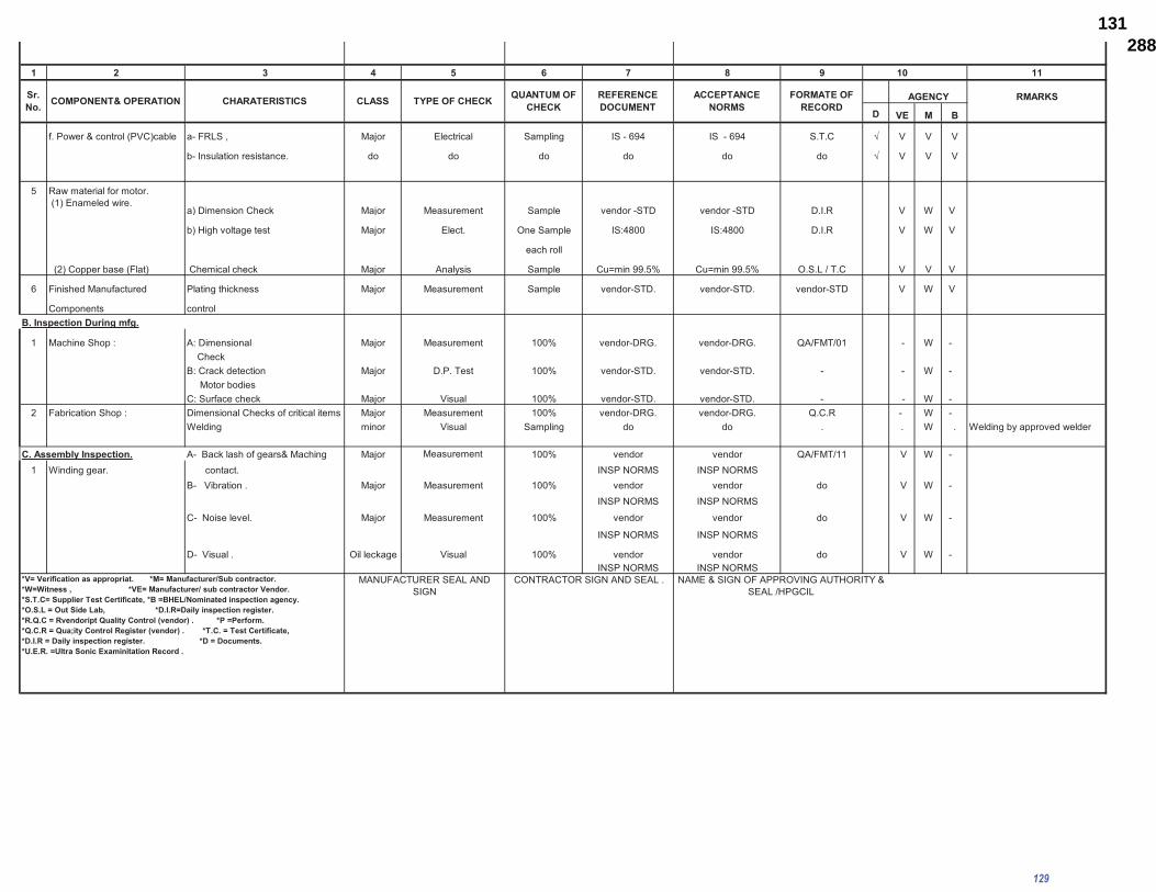
1 2 3 4 5 6 7 8 9 10 11
RMARKS
D VE M B
f. Power & control (PVC)cable a- FRLS , Major Electrical Sampling IS - 694 IS - 694 S.T.C √ V V V
b- Insulation resistance. do do do do do do √ V V V
5 Raw material for motor. (1) Enameled wire.
a) Dimension Check Major Measurement Sample vendor -STD vendor -STD D.I.R V W V
b) High voltage test Major Elect. One Sample IS:4800 IS:4800 D.I.R V W V
each roll
(2) Copper base (Flat) Chemical check Major Analysis Sample Cu=min 99.5% Cu=min 99.5% O.S.L / T.C V V V
6 Finished Manufactured Plating thickness Major Measurement Sample vendor-STD. vendor-STD. vendor-STD V W V
Components controlB. Inspection During mfg.
1 Machine Shop : A: Dimensional Major Measurement 100% vendor-DRG. vendor-DRG. QA/FMT/01 - W - CheckB: Crack detection Major D.P. Test 100% vendor-STD. vendor-STD. - - W - Motor bodiesC: Surface check Major Visual 100% vendor-STD. vendor-STD. - - W -
2 Fabrication Shop : Dimensional Checks of critical items Major Measurement 100% vendor-DRG. vendor-DRG. Q.C.R - W -Welding minor Visual Sampling do do . . W . Welding by approved welder
C. Assembly Inspection. A- Back lash of gears& Maching Major Measurement 100% vendor vendor QA/FMT/11 V W -1 Winding gear. contact. INSP NORMS INSP NORMS
B- Vibration . Major Measurement 100% vendor vendor do V W -INSP NORMS INSP NORMS
C- Noise level. Major Measurement 100% vendor vendor do V W -
INSP NORMS INSP NORMS
D- Visual . Oil leckage Visual 100% vendor vendor do V W -INSP NORMS INSP NORMS
*V= Verification as appropriat. *M= Manufacturer/Sub contractor. *W=Witness , *VE= Manufacturer/ sub contractor Vendor. *S.T.C= Supplier Test Certificate, *B =BHEL/Nominated inspection agency. *O.S.L = Out Side Lab, *D.I.R=Daily inspection register. *R.Q.C = Rvendoript Quality Control (vendor) . *P =Perform. *Q.C.R = Qua;ity Control Register (vendor) . *T.C. = Test Certificate, *D.I.R = Daily inspection register. *D = Documents. *U.E.R. =Ultra Sonic Examinitation Record .
Sr. No. COMPONENT& OPERATION CHARATERISTICS CLASS TYPE OF CHECK ACCEPTANCE
NORMSQUANTUM OF
CHECKREFERENCE DOCUMENT
FORMATE OF RECORD
AGENCY
CONTRACTOR SIGN AND SEAL . NAME & SIGN OF APPROVING AUTHORITY & SEAL /HPGCIL
MANUFACTURER SEAL AND SIGN
129
288648/2021/PS-PEM-MAX131

1 2 3 4 5 6 7 8 9 10 11
REMARKS
D VE M B
2 Motor Assembly : A-Winding Insulation test. Major High Volt. Test 100% I S :325-96 I S :325-96 D.I.R V W V
1.5 KV for 5 SEC 1.5 KV for 5 SEC. QA/FMT/13
B-Insulation Resistance Major Measurement 100% > 10 mega ohms > 10 mega ohms Test report V W V
C-Motor testing for elect. Pmt. Major Elect. 100% IS : 325 IS : 325 Test report V W V
D-Vibration measurement & noise lev Major Measurement 100% vendor - Norms vendor -Norms Test report V W .
3 Speed Governor Tripping speed Major Function Check 100% I S : 9878 I S : 9878 T.C V W V
Assembly : Easy Run test LCH -112 LCH - 112 IN Pant.
4 Controller Assembly / 1. Visual Inspection Major Visual 100% vendor Norms vendor Norms T.C V W V
VVVF Unit. 2. Electrical Checks (Routine Test). do Electrical 100% do do do V W V3. Functional Checks do Function 100% do do do V W V4. Pretreatment in seven tank for Major Measurement + Visual Sampling do do vendor - FMT. V W Vsheet & paint thickness.
Sr. No. COMPONENT& OPERATION CHARATERISTICS CLASS TYPE OF CHECK
MANUFACTURER SEAL AND SIGN
CONTRACTOR SIGN AND SEAL.
AGENCY
*V= Verification as appropriat. *M= Manufacturer/Sub contractor. *W=Witness , *VE= Manufacturer/ sub contractor Vendor. *S.T.C= Supplier Test Certificate, *B =BHEL/Nominated inspection agency. *O.S.L = Out Side Lab, *D.I.R=Daily inspection register. *R.Q.C = Rvendoript Quality Control (vendor) . *P =Perform. *Q.C.R = Qua;ity Control Register (vendor) . *T.C. = Test Certificate, *D.I.R = Daily inspection register. *D = Documents. *U.E.R. =Ultra Sonic Examinitation Record .
ACCEPTANCE NORMS
FORMATE OF RECORD
NAME & SIGN OF APPROVING AUTHIRITY & SEAL.
QUANTUM OF CHECK
REFERENCE DOCUMENT
130
288648/2021/PS-PEM-MAX132
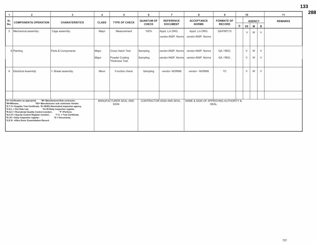
1 2 3 4 5 6 7 8 9 10 11
REMARKS
D VE M B
5 Mechanical assembly : Cage assembly . Major Measurement 100% Appd. L/o DRG. Appd. L/o DRG. QA/FMT/15 V W Vvendor-INSP. Norms vendor-INSP. Norms
6 Painting Parts & Components Major Cross Hatch Test Sampling vendor-INSP. Norms vendor-INSP. Norms QA / REG. V W V
Major Powder Coating Sampling vendor-INSP. Norms vendor-INSP. Norms QA / REG. V W VThickness Test
6 Electrical Assembly 1- Break assembly . Minor Function check Sampling vendor- NORMS vendor - NORMS TC V W V
AGENCYFORMATE OF RECORD
NAME & SIGN OF APPROVING AUTHORITY & SEAL
REFERENCE DOCUMENTCLASS TYPE OF CHECK
CONTRACTOR SIGN AND SEAL.*V= Verification as appropriat. *M= Manufacturer/Sub contractor. *W=Witness , *VE= Manufacturer/ sub contractor Vendor. *S.T.C= Supplier Test Certificate, *B =BHEL/Nominated inspection agency. *O.S.L = Out Side Lab, *D.I.R=Daily inspection register. *R.Q.C = Rvendoript Quality Control (vendor) . *P =Perform. *Q.C.R = Qua;ity Control Register (vendor) . *T.C. = Test Certificate, *D.I.R = Daily inspection register. *D = Documents. *U.E.R. =Ultra Sonic Examinitation Record .
MANUFACTURER SEAL AND SIGN
Sr. No. COMPONENT& OPERATION ACCEPTANCE
NORMSCHARATERISTICS QUANTUM OF CHECK
131
288648/2021/PS-PEM-MAX133

CLAUSE NO.
QUALITY ASSURANCE
KHURJA SUPER THERMAL POWER PROJECT (2X660 MW)
TURBINE GENERATOR AND ASSOCIATED PACKAGES
TECHNICAL SPECIFICATION SECTION-VI, PART-B
BID DOC NO. : THDC/RKSH/CC-9915-371
SUB-SECTION-E-20 ELEVATORS
PAGE 1 OF 1
ELECTRICAL PORTION OF PASSENGER / SERVICE ELEVATORS AND LIFTS
Items Description
Genera
l physic
al In
spection /
Dim
en
sio
ns
Functional/ O
pera
tional T
est
Burn
in T
est on o
n e
lectr
onic
card
s
Pre
-tre
atm
en
t in
se
ve
n t
an
k f
or
sheet ste
el , P
ain
ting
Pain
shade, th
ickness &
adhesio
n
All
Routine tests
as p
er
rele
va
nt
sta
nd
ard
Electrical Motor IS 325 / IS 4722 Y Y Y
PLC (IEC 1131) Y Y Y Y
VVVF Panel Y Y Y Y Y Y
Note :1) This is an indicative list of tests/checks. The manufacture is to furnish a
detailed Quality Plan indicating the practices & Procedure followed alongwith relevant supporting documents during QP finalisation.
2) Make of all major Bought Out Items will be subject to NTPC approval.
132
288648/2021/PS-PEM-MAX134

2X660 MW KHURJA STPP
TECHNICAL SPECIFICATION FOR ELEVATOR
SPECIFIC TECHNICAL REQUIREMENT -MECHANICAL
SPECIFICATION No: PE-TS-475-502-A001 SECTION IA REV. 00 APR 2021
PAINTING SPECIFICATION
133
288648/2021/PS-PEM-MAX135

CLAUSE NO.TECHNICAL REQUIREMENTS
KHURJA SUPER THERMAL POWER PROJECT (2X660 MW)
TURBINE GENERATOR AND ASSOCIATED PACKAGES
TECHNICAL SPECIFICATIONSSECTION VI, PART-B
BID DOC NO.: THDC/RKSH/CC-9915-371
SUB-SECTION - A-7SURFACE
PREPARATION & PAINTING
Page 1 of 5
1.00.00 Specification of surface preparation & painting
1.01.00 Surface preparation methods and paint/primer materials shall be of the type specified herein. If the contractor desires to use any paint/primer materials other than that specified,specific approval shall be obtained by the contractor in writing from the employer for using the substitute material.
1.02.00 All paints shall be delivered to job site in manufacturers sealed containers. Each container shall be labeled by the manunumber and colour.
1.03.00 Unless specified otherwise, paint shall not be applied to surfaces of insulation, surfaces of stainless steel/nickel/ copper/brass/ monel/ aluminum/ hastelloy/lead/ galvanized steel items, valve stem, pump rods, shafts, gauges, bearing and contact surfaces, lined or clad surfaces.
1.04.00 All pipelines shall be Colour coded for identification as per the NTPC Colour-coding scheme, which will be furnished to the contractor during detailed engineering.
1.05.0 SURFACE PREPARATION
1.05.01 All surfaces to be painted shall be thoroughly cleaned of oil, grease and other foreign matter. Surfaces shall be free of moisture and contamination from chemicals and solvents.
1.05.02 The following surface schemes are envisaged here. Depending upon requirement any one or a combination of these schemes may be used for surface preparation before application of primer.
SP1 Solvent cleaning
SP2 Application of rust converter (Ruskil or equivalent grade)
SP3 Power tool cleaning
SP4 Shot blasting (shot blasting shall be used as surface preparationmethod for hot worked pipes prior to application of primer)
SP4* Shot blast cleaning/ abrasive blast cleaning to SA21/2 (near white metal) 35-50 microns
SP5 Phospating
SP6 Emery sheet cleaning/Manual wire brush cleaning.
1.06.00 APPLICATION OF PRIMER/PAINT
1.06.01 application, handling and drying time shall be strictly followed and considered as part of this specification. The Dry film thickness (DFT) of primer/paint shall be as specified herein.
1.06.02 Surfaces prepared as per the surface preparation scheme indicated herein shall be applied with primer paint within 6 hours after preparation of surfaces.
1.06.03 Where primer coat has been applied in the shop, the primer coat shall be carefully examined, cleaned and spot primed with one coat of the primer before applying intermediate and finish coats. When the primer coat has not been applied in the shop, primer coat shall be applied by brushing, rolling or spraying on the same day as the surface is prepared. Primer coat shall be applied prior to intermediate and finish coats.
1.06.04 Steel surfaces that will be concealed by building walls shall be primed and finish painted before the floor is erected. Tops of structural steel members that will be covered by grating shall be primed and finish painted before the grating is permanently secured.
134
288648/2021/PS-PEM-MAX136

CLAUSE NO.TECHNICAL REQUIREMENTS
KHURJA SUPER THERMAL POWER PROJECT (2X660 MW)
TURBINE GENERATOR AND ASSOCIATED PACKAGES
TECHNICAL SPECIFICATIONSSECTION VI, PART-B
BID DOC NO.: THDC/RKSH/CC-9915-371
SUB-SECTION - A-7SURFACE
PREPARATION & PAINTING
Page 2 of 5
1.06.05 Following are the Primer/painting schemes envisaged herein:
PS3 - Zinc Chrome Primer (Alkyd base) by brush/Spray to IS104.
PS3* - Zinc Chrome primer (Alkyd base) by dip coat.
PS4 - Synthetic Enamel (long oil alkyd) to IS2932.
PS5 - Red Oxide Zinc Phosphate primer (Alkyd base) to IS 12744
PS9 - Aluminium paint to IS 2339.
PS9* - Heat resistant Aluminum paint to IS-13183 Gr.-I (for temperature 400 degC 600 degC), IS-13183 Gr.-II (for temperature 200 degC- 400
degC and IS-13183 Gr.-III (for temperature upto 200 degC)
PS13 - Rust preventive fluid by spray, dip or brush.
PS14 - Weldable primer-Deoxaluminate or equivalent.
PS16 - High Build Epoxy CDC mastic `
PS17 - Aliphatic Acrylic Polyurethane CDE134 ,%V=40.0(min.)
PS18 - Epoxy based TiO2 pigmented coat
PS19 - Epoxy based Zinc phosphate primer (92% zinc in dry film (min.), %VS=35.0(min.).
PS-20 - Epoxy based finish paint
1.06.06 All weld edge preparation for site welding shall be applied with one coat of wieldable primer.
1.06.07 For internal protection of pipes/tubes, VCI pellets shall be used at both ends after sponge testing and ends capped. VCI pellets shall not be used for SS components and composite assemblies.
135
288648/2021/PS-PEM-MAX137

1.06
.08
Prim
er/P
aint
ing
Sche
dule
Sl.
No
Des
crip
tion
Surf
ace
Prep
arat
ion
Prim
er C
oat
Inte
rmed
iate
Coa
tFi
nish
Coa
tsTo
tal
Min
. Pa
intin
gD
FT(M
icro
ns)
Col
our
Shad
e
Type
of Pr
imer
No.
of C
oat
s
Min
. DFT
/ c
oat
(Mic
rons
)
Type
of co
atin
g
No.
C
oat
s
Min
. D
FT/
Coa
t (M
icro
ns)
Type
of
coat
ing
No.
C
oats
Min
. D
FT/
Coa
t (M
icro
ns)
A) P
ower
Cyc
le P
ipin
g
As p
er
NT
PC
C
olo
ur
sh
ad
e/
co
din
g
sch
em
e
1.
All
insu
late
d P
ipin
gs,
fitt
ing
s/
co
mp
on
en
ts,
Pip
e c
lam
ps,
Ve
ssels
/Ta
nks,
Eq
uip
me
nts
etc
.S
P3
/SP
4P
S 9
*1
20
--
-P
S9
*1
20
40
2.
All
un
- in
su
late
d
Pip
ing
s,
fitt
ing
s/
co
mp
on
en
ts,
Pip
e c
lam
ps,
Ve
sse
ls/T
an
ks,
Eq
uip
me
nts
etc
.
De
sig
nte
mp
era
ture
<
or
eq
ua
l to
60
CS
P3
/SP
4P
S 5
22
5-
--
PS
43 $
35
$
15
5$
De
sig
nte
mp
era
ture
a
bo
ve
60
C-
20
0C
SP
3/S
P4
PS
9*
12
0-
--
PS
9*
12
04
0
De
sig
n
tem
pe
ratu
re
>
20
0C
SP
3/S
P4
PS
9*
12
0-
--
PS
9*
12
04
0
3C
on
sta
nt
Lo
ad
Ha
ng
er
(CL
H),
V
aria
ble
Lo
ad
Ha
ng
er
(VL
H).
SP
4*
PS
19
14
0-
--
PS
17
13
07
0
4.
Pip
ing
ha
ng
er s
/ su
pp
ort
s (
oth
er
tha
n
(3)
ab
ove
.
(un-in
su
late
d)
SP
3/S
P5
PS
52
25
--
-P
S4
22
51
00
5.
Va
lve
s
136
288648/2021/PS-PEM-MAX138

Ca
st/
Fo
rge
d
De
sig
n
tem
pe
ratu
re <
or
eq
ua
l to
60
de
gC
#
SP
3/S
P5
PS
52
35
--
-P
S4
22
51
20
De
sig
n
tem
pe
ratu
re
ab
ove
60
de
gC
S
P3
/SP
5P
S 9
*1
20
--
-P
S9
*1
20
40
6.
All
auxili
ary
Str
uctu
ral
Ste
el
co
mp
on
en
ts
for
pip
e
su
pp
ort
s
Ou
tsid
e T
G b
uild
ing
a
nd
in
SG
en
ve
lop
eS
P4
*
Ino
rga
nic
Eth
yl
Zin
c
Sili
ca
te
17
5P
S1
81
75
a))
Epoxy
co
at
b)F
ina
l co
at
of
p
ain
t P
S1
7
2 1
35
30
25
0
With
in
TG
bu
ildin
gS
P4
*-d
o-
13
5P
S1
81
35
a))
Epoxy
co
at
b)F
ina
l co
at
of
p
ain
t P
S1
7
2 1
25
30
15
0
7.
We
ld E
dg
es
SP
6(H
an
d
cle
an
ing
b
y w
ire
b
rush
ing
)
PS
13
(W
eld
ab
le
prim
er)
12
5-
--
--
-2
5
137
288648/2021/PS-PEM-MAX139

1.
$ T
he
first
2 f
inis
he
d c
oa
ts (
tota
l m
in.D
FT
of
70
mic
ron
s)
sh
all
be
do
ne
at
sh
op
an
d t
he
3rd
fin
ish
co
at
(min
.DF
T 3
5 M
icro
ns)
sh
all
be
ap
plie
d a
t site
.2
. F
or
va
lve
s b
elo
w 6
5N
B a
nd
te
mp
era
ture
up
to a
nd
in
clu
din
g 5
40
De
g.C
, P
ark
erizin
g/z
inc p
ho
sp
ha
te c
orr
osio
n r
esis
tan
t co
atin
ga
s p
er
AS
TM
F1
13
7 is a
lso
acce
pta
ble
in
lie
u o
f A
lum
inu
m p
ain
t.3
. F
or
co
rro
sio
n p
rote
ctio
n o
f th
rea
de
d h
an
ge
r ro
ds a
nd
va
ria
ble
sp
rin
g c
ag
es,
ele
ctr
o g
alv
an
izin
g in
fu
ll co
mp
lian
ce
to
min
im
um
Co
rro
sio
n c
ate
go
ry C
3 a
s p
er
E
N I
SO
12
94
4 is a
lso
acce
pta
ble
.4
. F
or
sp
rin
g c
ag
es
-o
f A
cry
lic r
esin
Co
-ve
sp
ecifie
d p
ain
t sch
em
e.
5.
Fo
r co
rro
sio
n p
rote
ctio
n f
or
all
inn
er
pa
rts o
f th
e h
an
ge
rs s
ha
ll b
e a
tle
ast
in f
ull
co
mp
lian
ce
to
Co
rro
sio
n c
ate
go
ry C
3 a
s p
er
EN
IS
O1
29
44
.6
. #
-F
or
Ca
st/
forg
ed
va
lve
s u
pto
& in
clu
din
g d
esig
n t
em
pe
ratu
re 6
0D
eg
.C,
Alu
min
ium
p
ain
tin
g a
s p
er
IS-1
31
83
Gr-
3 o
r b
ett
er
with
to
tal D
FT
40
Mic
ron
is a
lso
a
cce
pta
ble
.
B) L
OW
PR
ESSU
RE
PIPI
NG
Surf
ace
Prep
arat
ion
Type
of
Prim
erN
o.of C
oats
Min
. DFT
/ co
at
(Mic
rons
)Ty
pe o
f co
atin
gN
o.C
oats
Min
. DFT
/C
oat
(Mic
rons
)Ty
pe o
f co
atin
gN
o.C
oat
s
Min
. DFT
/C
oat
(Mic
rons
)
Min
. Tot
al
DFT
(Mic
rons
)
1A
ll P
ipin
g,
fitt
ing
s /
co
mp
on
en
ts,
va
lve
s,
Eq
uip
me
nts
etc
.S
P3
/SP
5P
S3
/P
S5
22
5P
S 4
13
0P
S 4
23
51
50
As p
er
NT
PC
C
olo
ur
sh
ad
e/
co
din
g
sch
em
e
2S
tain
less s
tee
l su
rfa
ce
,G
alv
an
ize
d
ste
el su
rfa
ce
an
d g
un
me
tal su
rfa
ce
.N
o P
ain
tin
g
3O
n t
he
in
tern
al su
rfa
ce
fo
r p
ipe
s
10
00
Nb
an
d a
bo
ve
A c
oa
t o
f p
rim
er
follo
we
d b
y h
ot
co
al-
tar
en
am
el o
r co
al ta
r e
po
xy p
ain
tin
g (
co
ld)
sh
all
be
ap
plie
d.
138
288648/2021/PS-PEM-MAX140

2X660 MW KHURJA STPP
TECHNICAL SPECIFICATION FOR ELEVATOR
SPECIFIC TECHNICAL REQUIREMENT -MECHANICAL
SPECIFICATION No: PE-TS-475-502-A001 SECTION IA REV. 00 APR 2021
ANNEXURE-I
LIST OF MAKES
SR. NO. ITEM SUPPLIERS PLACE REMARKS
1. WIRE ROPES
USHA MARTIN RANCHI BHARAT WIRE ROPE MUMBAI.
2. TRAILING CABLE
GEBAUR & GRILLER- AUSTRIA DAETWYLER (THELMA) CABLES- SWITZERLAND SWITZERLAND
LAPP GERMANY UNIVERSAL - INCABSTEP -
3. BUFFER SPRINGS
INDUSTRIAL STEEL SPRING - ALL INDIA STEEL SPRING MANUFACTURING COMPANY -
KOLKATA SHAW COMPANY KOLKATA SUPER INDIA SPRINGS KOLKATA MESCO SPRING. MUMBAI.
4. GEAR INTERNALS
PREMIMUM ENERGY TRANSMISSION LTD, PUNE
SICOR S.P.A- ITLY OEM
5. DRIVER MOTOR
Siemens MUMBAI ABB FARIDABAD BHARAT BIJILI - CGL - KIRLOSKER ELECTRIC CO LTD - OEM - ASEA BROWN BOVERI NGEF MARATHON GE-POWER RAJINDRA ELECT INDUSTRIES LAXMI HYDRAULICS PVT. LTD
6. STAINLESS STEEL
SAIL, - MINOX METAL, - JINDAL -
7. CR SHEET ESSAR STEELS, - BHUSHAN STEELS -
8. CABLES
DELTON, - NICCO - UNIVERASL, - FINOLEX, -
139
288648/2021/PS-PEM-MAX141

2X660 MW KHURJA STPP
TECHNICAL SPECIFICATION FOR ELEVATOR
SPECIFIC TECHNICAL REQUIREMENT -MECHANICAL
SPECIFICATION No: PE-TS-475-502-A001 SECTION IA REV. 00 APR 2021
SR. NO. ITEM SUPPLIERS PLACE REMARKS
CCI - MACROTHREM, - VARSHA CABLES - KEI. - PARAMOUNT - POLYCAB. -
9. RELAYS
SIEMENS - SCHNEIDER TELEMECHANIQUE - SALZER, - SCHNIDER ELECTRIC. -
10. CONTACTORS
SIEMENS - L&T - GE - SCHNEIDER TELEMECHANIQUE. -
11. TRANSFORMERS
SHARP ELECTRONICS - MELCON CONTROLS CHENNAI LOGITECH - GUNHAWA ELECTRIC CO LTD. -
12. INVERTOR (V3F)
YASKAWA- GERMANY TOSHIBA JAPAN.
13. T GUIDES
SAVERA CHINA D.D HITECH -
14. CAR DOOR OPERATOR
Wittur GMBH AUSTRIA FERMATOR - OEM -
15. INFRA-RED DOOR CURTAIN
MEMCO UK WECO - TLJONES -
16. BATTERY (LEAD ACID)
EXIDE. HBL POWER SYSTEM- HYDERABAD AMAR RAJA TIRUPATI AMCO SAFT INDIA LTD BANGALORE.
NOTE:
1. THE SUB VENDOR LIST ABOVE IS INDICATIVE ONLY AND IS SUBJECT TO BHEL AND
CUSTOMER APPROVAL DURING DETAILED ENGINEERING STAGE WITHOUT ANY COMMERCIAL & DELIVERY IMPLICATION TO BHEL.
BIDDER TO PROPOSE SUB VENDOR WITHIN 4 WEEKS OF PLACEMENT OF LOI. THEREAFTER NO REQUEST FOR ADDITIONAL SUB-VENDOR SHALL BE ENTERTAINED.
140
288648/2021/PS-PEM-MAX142

2X660 MW KHURJA STPP
TECHNICAL SPECIFICATION FOR ELEVATOR
SPECIFIC TECHNICAL REQUIREMENT -MECHANICAL
SPECIFICATION No: PE-TS-475-502-A001 SECTION IA REV. 00 APR 2021
2. IN CASE OF ASSEMBLED IMPORTED ELEVATOR, MAKES OF BOI SHALL BE SUBJECT TO
BHEL/ CUSTOMER APPROVAL DURING DETAIL ENGINEERING STAGE WITHOUT ANY COMMERCIAL IMPLICATION AT CONTRACT STAGE.
3. DEALERS ARE NOT ACCEPTABLE FOR ANY ITEM OF THE PACKAGE. BIDDER SHALL
PROCURE ALL ITEMS INCLUDING PLATES, STRUCTURAL ETC. FROM APPROVED SUB VENDOR ONLY.
141
288648/2021/PS-PEM-MAX143

2X660 MW KHURJA STPP
TECHNICAL SPECIFICATION FOR ELEVATOR
SPECIFIC TECHNICAL REQUIREMENT -MECHANICAL
SPECIFICATION No: PE-TS-475-502-A001 SECTION IA REV. 00 APR 2021
ANNEXURE-II MANDATORY SPARES
142
288648/2021/PS-PEM-MAX144

2X660 MW KHURJA STPP
TECHNICAL SPECIFICATION FOR ELEVATOR
SPECIFIC TECHNICAL REQUIREMENT -MECHANICAL
SPECIFICATION No: PE-TS-475-502-A001 SECTION IA REV. 00 APR 2021
ANNEXURE-II List of Mandatory Spares for elevator.
One (1) set of list of Mandatory Spares common for TG building elevator & Service Building elevator shall be provided.
List of Mandatory spares for TG building elevator and Service Building Elevator.
Sl. No. Description Quantity (Units) 1 Over current relay 2 Nos. of each type 2 Auxiliary relays 3 Nos. of each type 3 Friction block 2 Nos. 4 Guide roller of each type 20% of total population or 3 Nos. of each
type whichever is high 5 Contactors of each type 2 Nos. 6 Control transformer 1 No. of each type 7 Time device 2 Nos. of each type 8 Rectifiers 2 Nos. of each type 9 Resistor 3 Nos. of each type
10 Fuses of each rating 20% of the total population 11 Limit switches of each type 3 Nos. 12 Push button 3 Nos. of each type 13 Contact device (if applicable) 3 Nos. of each type 14 Brake motor 2 Nos. of each type 15 Transmitters 2 Nos. of each type 16 Switches of each type 3 Nos. 17 Receiver 2 Nos. of each type 18 Bearings of each type & size 2 Nos. 19 Roller of each type 3 Nos. 20 Worm gear spares
20.1 'O' rings 3 Sets 20.2 Sealing ring of each type 3 Sets 21 Spares for brake
21.1 a) Fan 2 Nos. of each type 21.2 b) Magnetic coil 3 Nos. of each type 21.3 c) Brake disc 2 Sets 21.4 d) Brake pad 2 Sets 22 Bushing (for door front) 2 Sets 23 Pinion 2 Nos. of each type 24 Lift Main drive motor 01 no of each type & rating. 25 Door opening motor 01 no of each type & rating. 26 Landing door complete 01 no. 27 Car door complete 01 no 28 VFD drive 01 no of each type & rating.
Note: a) Unless stated otherwise, a ‘set’ means item or sub-items required for each type/ size, range
of assembly/ sub- assembly required for complete replacement in one equipment system; it is further intended that the assembly/ sub-assembly which have different orientation ( like left hand or right hand, top or bottom), different direction of rotation or mirror image positioning or any other reasons which result in marinating two different sets of spares to be used for
143
288648/2021/PS-PEM-MAX145

2X660 MW KHURJA STPP
TECHNICAL SPECIFICATION FOR ELEVATOR
SPECIFIC TECHNICAL REQUIREMENT -MECHANICAL
SPECIFICATION No: PE-TS-475-502-A001 SECTION IA REV. 00 APR 2021
subject assembly/ sub assembly, these shall be considered as different type of assembly/ sub assembly.
b) Wherever quantity has been specified as percentage (%), the quantity of mandatory spares to be provided by the vendor shall be the specified percentage (%) of total population required to meet the specification requirements. In case the quantity of mandatory spares so calculated happens to be in fraction, the same shall be rounded off to next higher whole number.
c) Wherever the quantities have been indicated for each type, size, thickness, material, radius, range etc, these shall cover all the items supplied and installed and the breakup of these shall be furnished by the vendor during detail engineering.
d) In case spares indicated in the list are not applicable to the particular design offered by the bidder, the bidder should offer spares applicable to the offered design with quantities generally in line with the approach followed in the above list.
e) Wherever bidder has indicated an item as not applicable, the same will have to be supplied free of cost, in case it is found applicable during detail engineering.
f) Interchangeability and Packings: All spares supplied under this contract shall be strictly interchangeable with parts for which they are intended for replacements. These spares should include all mounted accessories like components, boards, add or items, fitting, connectors etc. and be complete in all respects so that the replacement of the main items by these spares does not require any additional item. The vendors must conform the pair to pair compatibility of each electrical spares modules with the modules should be supplied in the original package. All electronic modules should be pre set and/or preprogrammed for ready use at site. Alternatively, suitable instruction sheet indicating the details of required PCB jumper position, BCD which is setting, EPROM/PROM listing etc should be packed along with each module. Also a caution mark sign should be put on all such module which needs pre setting /pre-programming before putting them in to service. The spare shall be treated and properly packed for long term storage.
g) Identification: Each spare shall be clearly marked and labeled on the outside of the packing with its description. When more than one spare part is packed in single case, a general description of the contents shall be shown on the outside of such case and a detailed list enclosed. All cases, containers and other packages must be suitably marked and numbered for the purpose of identification.
144
288648/2021/PS-PEM-MAX146

2X660 MW KHURJA STPP
TECHNICAL SPECIFICATION FOR ELEVATOR
SPECIFIC TECHNICAL REQUIREMENT -MECHANICAL
SPECIFICATION No: PE-TS-475-502-A001 VOL IIB SECTION IA REV. 00 APR 2021
ANNEXURE-III
LIST OF TOOLS AND TACKLES
145
288648/2021/PS-PEM-MAX147
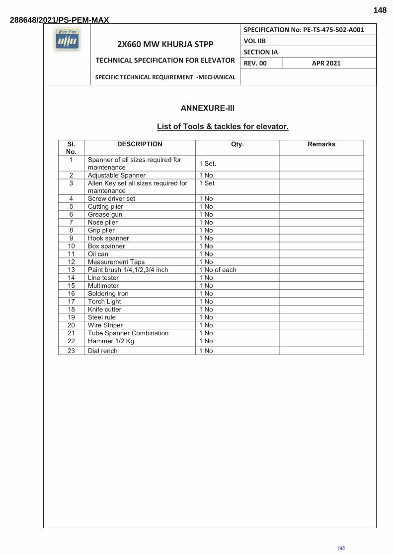
2X660 MW KHURJA STPP
TECHNICAL SPECIFICATION FOR ELEVATOR
SPECIFIC TECHNICAL REQUIREMENT -MECHANICAL
SPECIFICATION No: PE-TS-475-502-A001 VOL IIB SECTION IA REV. 00 APR 2021
ANNEXURE-III
List of Tools & tackles for elevator.
Sl. No.
DESCRIPTION Qty. Remarks
1 Spanner of all sizes required for maintenance 1 Set.
2 Adjustable Spanner 1 No 3 Allen Key set all sizes required for
maintenance 1 Set
4 Screw driver set 1 No 5 Cutting plier 1 No 6 Grease gun 1 No 7 Nose plier 1 No 8 Grip plier 1 No 9 Hook spanner 1 No 10 Box spanner 1 No 11 Oil can 1 No 12 Measurement Taps 1 No 13 Paint brush 1/4,1/2,3/4 inch 1 No of each 14 Line tester 1 No 15 Multimeter 1 No 16 Soldering iron 1 No 17 Torch Light 1 No 18 Knife cutter 1 No 19 Steel rule 1 No 20 Wire Striper 1 No 21 Tube Spanner Combination 1 No 22 Hammer 1/2 Kg 1 No 23 Dial rench 1 No
146
288648/2021/PS-PEM-MAX148

2X660 MW KHURJA STPP
TECHNICAL SPECIFICATION FOR ELEVATOR
SPECIFIC TECHNICAL REQUIREMENT -MECHANICAL
SPECIFICATION No: PE-TS-475-502-A001 SECTION IA REV. 00 APR 2021
ANNEXURE-IV
Drawing document submission schedule
S.N0. Description Schedule 1 First submission of dwg/
docs as per MDL Within two (2) weeks from placement of LOI.
2 Every repeat submission Within one (1) week. 3 Response time by BHEL Within three (3) weeks after receiving of drawing.
Note: 1.0 The above are the minimum quantity of drawings/documents required. The exact
requirement shall be informed to the successful bidder during detail engineering stage for which no commercial implication shall be entertained by BHEL.
2.0 Bidder to note that BHEL reserves the right for drawing/document submission through web
based Document Management System. Bidder would be provided access to the DMS for drawing/document approval and adequate training for the same. Detailed methodology would be finalized during the kick-off meeting. Bidder to ensure following at their end.
• Internet explorer version – Minimum Internet Explorer 7. • Internet speed – 2 mbps (Minimum preferred). • Pop ups from our external DMS IP (124.124.36.198) should not be blocked. • Vendor’s internal proxy setting should not block DMS application’s link (http://124.124.36.198/wrenchwebaccess/login.aspx).
147
288648/2021/PS-PEM-MAX149

2X660 MW KHURJA STPP
TECHNICAL SPECIFICATION FOR ELEVATOR
SPECIFIC TECHNICAL REQUIREMENT -MECHANICAL
SPECIFICATION No: PE-TS-475-502-A001 VOL IIB SECTION IA REV. 00 APR 2021
ANNEXURE-V
MDL FOR ELEVATOR
S.N0. BHEL DOC No TITLE PURPOSE
1 PE-V0-475-502-A001 TDS OF TG BUILDING ELEVATOR A 2 PE-V0-475-502-A021 TDS OF SERVICE BUILDING ELEVATOR A 3 PE-V0-475-502-A007 GA, M/C ROOM LAYOUT, SCOPE & BOM OF
PASSENGER ELEVATOR (TG BUILDING) A
4 PE-V0-475-502-A008 GA, M/C ROOM LAYOUT, SCOPE & BOM OF PASSENGER ELEVATOR (SERVICE BUILDING)
A
5 PE-V0-475-502-A013 MQP FOR ELEVATOR (Common for TG BUILDING and Service building)
A
6 PE-V0-475-502-A014 O&M MANUAL FOR ELEVATOR (Common for TG BUILDING and Service building)
I
7 PE-V0-475-502-A015 WIRING DIAGRAM & POWER DISTRIBUTION SCHEMATIC (For each Elevator)
I
A= APPROVAL I= INFORMATION
148
288648/2021/PS-PEM-MAX150

2X660 MW KHURJA STPP
TECHNICAL SPECIFICATION FOR ELEVATOR
SPECIFIC TECHNICAL REQUIREMENT -MECHANICAL
SPECIFICATION No: PE-TS-475-502-A001 SECTION IA REV. 00 APR 2021
ANNEXURE-VI
CHECK LIST FOR OPERATION & MAINTENANCE MANUAL
Project name : Project number : Package Name : PO reference : Document number : Revision number :
Sl.no. & Sections
Description Tick ( √ )if included in Manual
Remarks
Yes No Not Applicable
1. Cover page
1.1 Project Name 1.2 Customer/consultant Name 1.3 Name of Package 1.4 Supplier details with phone, FAX ,email address
, Emergency Contact number
1.5 Name and sign of prepared by , checked by & approved by
1.6 Revision history with approval Details 2.0 Index
2.1 showing the sections & related page nos All the pages should be numbered section wise
3.0 Description of Plant/System
3.1 Description /write up of operating principle of system equipment/ associated sub-systems & accessories/controls system , operating conditions, performance parameters under normal , start up and special cases
3.2 Equipment list and basic parameter with Tag numbers
3.3 Data sheets approved by Customer/for information and catalogues provided by original manufacturer
3.4 Associated other packages and Interface /terminal points
3.5 P&ID & Process Diagrams 3.6 GA Layout drawings, As-built drawings , Actual
photograph of items/system (Drawings of A2 & bigger sizes are to be attached in the last)
3.7 Single line/wiring diagrams 3.8 Control philosophy /control write-ups 4.0 Commissioning Activities (if not covered in
separate document i.e. erection manual, commissioning manual)
4.1 Pre-Commissioning Checks 4.2 handling of items at site 4.3 Storage at site
149
288648/2021/PS-PEM-MAX151

2X660 MW KHURJA STPP
TECHNICAL SPECIFICATION FOR ELEVATOR
SPECIFIC TECHNICAL REQUIREMENT -MECHANICAL
SPECIFICATION No: PE-TS-475-502-A001 SECTION IA REV. 00 APR 2021
4.4 Unpacking & Installation procedure 5.0 Operation Guidelines for plant
personal/user/operator
5. 1 Interlock & Protection logic along with the limiting values of protection settings for the equipment along with brief philosophy behind the logic, drawings etc. to be provided.
5. 2 Start up, normal operation and shut down procedure for equipments along with the associated systems in step by step mode. Valve sequence chart, step list, interlocks etc. with Equipment isolating procedures to be mentioned.
5. 3 Do’s & Don’t of the equipments. 5. 4 Safety precautions to be taken during normal
operation. Safety symbols, Emergency instructions on total power failure condition/lubrication failure/any other condition
5. 5 Parameters to be monitored with normal values and limiting values
5. 6 Trouble shooting with causes and remedial measures
5. 7 Routine operational checks, recommended logs & records
5. 8 Changeover schedule if more than one auxiliary for the same purpose is given
5. 9 Painting requirement and schedule 5. 10 Inspection, repair , Testing and calibration
procedures
6.0 Maintenance guidelines for plant personal
6.1 List of Special Tools and Tackles required for Overhaul/Trouble shooting including special testing equipment required for calibration etc.
6.2
Stepwise dismantling and re-assembly procedure clearly specifying the tools to be used, checks to be made, records to be maintained, clearances etc. to be mentioned. Tolerances for fitment of various components to be given.
6.3 Preventive Maintenance & Overhauling schedules linked with running hours/calendar period along with checks to be given
6.4 Long term maintenance schedules especially for structural, foundations etc.
6.5 Consumable list along with the estimated quantity required during commissioning, normal running and during maintenance like Preventive Maintenances and Overhaul. Storage/handling requirement of consumables/self-life.
6.6 List of lubricants with their Indian equivalent, Lubrication Schedule, Quantity required for each equipment for complete replacement is to be
150
288648/2021/PS-PEM-MAX152

2X660 MW KHURJA STPP
TECHNICAL SPECIFICATION FOR ELEVATOR
SPECIFIC TECHNICAL REQUIREMENT -MECHANICAL
SPECIFICATION No: PE-TS-475-502-A001 SECTION IA REV. 00 APR 2021
given 6.7 List of vendors & Sub-vendors with their latest
addresses, service centres, Telephone Nos., Fax Nos., Mobile Nos., e-mail IDs etc.
6.8 List of mandatory and recommended spare parts list
6.9 Tentative Lead time required for ordering of spares from the equipment supplier
6.10 Guarantee and warranty clauses 7.0 Statutory and other specific requirements
considerations.
8.0 List of reference documents 9.0 Binding as per requirement
151
288648/2021/PS-PEM-MAX153

PROJECT ENGINEERING MANAGEMENT, POWER SECTOR
BHARAT HEAVY ELECTRICALS LIMITED-NOIDA
ANNEXURE-VII
152
288648/2021/PS-PEM-MAX154

CONTENT
1 SCOPE OF THE DOCUMENT
2 PURPOSE OF STORAGE & PRESERVATION
3 MEASURES TO BE TAKEN FOR STORAGE AND PRESERVATION
a) GENERAL STORAGE REQUIREMENTS
b) GENERAL PRESERVATION REQUIREMENTS
c) GENERAL INSPECTION REQUIREMENTS
4 TYPE OF STORAGE FOR VARIOUS EQUIPMENT
5. CONCLUSION
6. STACKING ARRANGEMENT FOR PLATES AND STRUCTURAL STEEL
153
288648/2021/PS-PEM-MAX155

1. SCOPE OF THE DOCUMENT
This guideline is prepared in intent to provide proper site storage and preservation of the
Mechanical, Electrical and C & I items / equipment supplied under various bought out
packages/items. This storage procedure shall be followed at different power plant sites by
concerned agency for storage and preservation from the date of equipment received at
site until the same are erected and handed over to the customer.
2. PURPOSE OF STORAGE & PRESERVATION
Many of the items may be required to be kept in stores for long period. It shall therefore
be essential that proper methods of storage and preservation be applied so that items do
not deteriorate, loose some of their properties and become unusable due to atmospheric
conditions and biological elements.
3. MEASURES TO BE TAKEN FOR STORAGE, HANDLING & PRESERVATION
a) GENERAL STORAGE REQUIREMENTS
1. To the extent feasible, materials should be stored near the point of erection. The
storage areas should have adequate unloading and handling facilities with adequate
passage space for movement of material handling equipment such as cranes, fork lift
trucks, etc. The storage of materials shall be properly planned to minimise time loss
during retrieval of items required for erection.
2. The outdoor storage areas as well as semi-closed stores shall be provided with
adequate drainage facilities to prevent water logging. Adequacy of these facilities shall
be checked prior to monsoon.
3. The storage sheds shall be built in conformity with fire safety requirements. The stores
shall be provided with adequate lights and fire extinguishers. ‘No smoking’ signs shall
be placed at strategic locations. Safety precautions shall be strictly enforced.
4. Adequate lighting facility shall be provided in storage areas and storage sheds and
security personnel positioned to ensure enforcement of security measures to prevent
theft and loss of materials.
5. Adequate number of competent stores personnel and security staff shall be deployed
to efficiently store and maintain the equipment / material.
7. The equipment shall be stored in an orderly manner, preserving their identification
slips, tags and instruction booklets, etc., required during erection. The storage of
materials shall be equipment-wise. Loose parts shall be stored in sheds on racks,
Page 1 of 13
154
288648/2021/PS-PEM-MAX156

preserving the identification marks and tags in good condition. The group codes shall
be displayed on the racks
6. At no time shall any materials be stored directly on ground. All materials shall be
stored minimum 200 mm above the ground preferably on wooden sleepers
b) GENERAL PRESERVATION REQUIREMENTS
1. All special measures to prevent corrosion shall be taken like keeping material in dry
condition, avoiding the equipment coming in contact with corrosive fluid like water,
acid etc.
2. Materials which carry protective coating shall not be wrapped in paper, cloth, etc., as
these are liable to absorb and retain moisture. The material shall be inspected and in
case of signs of wear or damages to protective coating, that portion shall be cleaned
with approved solution and coated with an approved protective paint. Complete record
of all such observations and protective measures taken shall be maintained.
3. Generally equipment supplied at site are properly greased or rust protective oil is
applied on machined/ fabricated components. However periodic inspection shall be
carried out to ensure that protection offered is intact.
4. While handling the equipment, no dragging on the ground is permitted. Avoid using
wire rope for lifting coated components. Use polyester slings (if possible) otherwise
protective material (e.g. clothes, wood block etc.) should be used while handling the
components with rope / slings
5. For Equipment supplied with finished paint, touch paint shall be done in case any
surface paint gets peeled off during handling. Otherwise such surfaces shall
necessarily be wrapped with polythene to avoid any corrosion. Further for equipment
wherein finish coat is to be applied at site, site to ensure that equipment is received
with primer coat applied.
6. It shall be ensured by periodic inspection that plastic inserts are intact in tapped holes,
wherever applicable.
7. Pipes shall be blown with air periodically and it shall be ensured that there is no
obstruction.
8. Silica gel or approved equivalent moisture absorbing material in small cotton bags
shall be placed and tied at various points on the equipment, wherever necessary.
9. Heavy rotating parts in assembled conditions shall be periodically rotated to prevent
corrosion/jamming due to prolonged storage.
Page 2 of 13
155
288648/2021/PS-PEM-MAX157

10. All the electrical equipment such as motors, generators, etc. shall be tested for
insulation resistance at least once in three months and a record of such measured
insulation values shall be maintained.
11. Following preservatives/preservation methods can be used depending upon type of
equipment
a. Rust preventive fluid (RPF)
b. Rust protective paints
c. Tarpaulin covers, in case of outdoor storage
d. De-oxy aluminate for weld-ments
c) GENERAL INSPECTION REQUIREMENTS
1. Period inspection of materials with specific reference to –
� Ingress of moisture and corrosion damages.
� Damage to protective coating.
� Open ends in pipes, vessels and equipment -
- In case any open ends are noticed, same shall be capped.
2. Any damages to equipment / materials.
- In case of any damages, these shall be promptly notified and in all cases, the
repairs / rectification shall be carried out.
- Any items found damaged or not suitable as per project requirements shall be
removed from site. If required to store temporarily, they shall be clearly
marked and stored separately to prevent any inadvertent use.
Page 3 of 13
156
288648/2021/PS-PEM-MAX158

4. TYPE OF STORAGE FOR VARIOUS EQUIPMENT
The types of storage are broadly classified under the following heads:
i Closed storage with dry and dust free atmosphere. (C )
The closed shed can be constructed by using cold-rolled / tubular components for
structure and corrugated asbestos sheets / galvanised iron sheets for roofing. Brick
walls / asbestos sheets can be used to cover all the sides. The floor of the shed can
be finished with plain cement concrete suitably glazed. The shed shall be provided
with proper ventilation and illumination.
ii Semi-closed storage. (S)
The semi closed shed can be constructed by using cold-rolled / tubular components
for structure and corrugated / asbestos sheets for roofing. The floor shall be brick
paved. If required a small portion of sides can be covered to protect components from
rainwater splashing onto the components.
Page 4 of 13
157
288648/2021/PS-PEM-MAX159

iii Open storage (O )
The open yard shall be levelled, well consolidated to achieve raised ground with the
provision of feeder roads for crane approach along with access roads running all
sides. One part of the open yard shall be stone pitched, levelled and consolidated with
raised ground suitable for storing / stacking heavier and critical components with due
space to handle them by cranes etc . Adequate number of sleepers, concrete block
etc. to be provided to make raised platforms to stack critical materials.
A separate yard to be identified as “scrap yard” slightly away from main open yard to
store wooden/steel scraps, which are to be disposed off. This is required to avoid mix
up with regular components as well as to avoid fire hazard.
Some of the components, which are having both machined & un-machined surfaces
and are bulky, shall be stored in open storage area on a raised ground and suitably
covered with water proof / fire retardant tarpaulin.
Page 5 of 13
158
288648/2021/PS-PEM-MAX160

The equipment listed below shall be stored and inspected as per requirement mentioned in the
table below.
Sl. No. Description of the equipment Type of Storage Check for Remarks
Raw material /mechanical items like pipes, plates, structure sections etc.)
1. Steel pipes ( lined/unlined) S
Damage , paint,
corrosion, rubber
lining peeling
Provide end
cap
2. MS Plates SDamage, paint,
corrosion
3. SS Plates S Damage
4. Non-metallic pipes S Damage, cracks Provide end
cap
5. Stainless steel pipes S Damage , Provide end
cap
6. MS sections, beams SDamage, paint,
corrosion
7. Cable trays SDamage, condition of
preservations
8. Insulation sheets S Damage
9. Insulation C Damage, packing
10. Hangers Rods SDamage, paint,
packing
11. Tubes SDamage, paint ,
packing
Provide end
cap
12. Hume pipes O Damage
13. Castings ODamage, paint,
corrosion
Fabricated mechanical items (pressure vessels, tanks etc.)
14. Pressure vessels (unlined) O Damage, paint,
corrosion,
Covered
nozzles
15.Atmospheric storage tanks
(unlined) O
Damage, paint,
corrosion
Covered
nozzles
Page 6 of 13
159
288648/2021/PS-PEM-MAX161

Sl. No. Description of the equipment Type of Storage Check for Remarks
16. Pressure vessels (lined) S
Damage, paint,
corrosion, rubber
lining
17. Atmospheric storage tanks(lined) S
Damage, paint,
corrosion, rubber
lining
18. Support structures ODamage , paint,
corrosion
19. Flanges CDamage , paint,
corrosion
20. Fabricated pipes SDamage , paint,
corrosion
Provide end
cap
21. Vessels internals CDamage , paint,
corrosion ,packing
22. Grills SDamage , paint,
corrosion
23. Angles SDamage , paint,
corrosion
24.Bridge mechanism/clarifier
mechanism O
Damage , paint,
corrosion
25. Cranes, rails SDamage , paint,
corrosion
26. Stair cases ODamage , paint,
corrosion
27. Ladders/handrails ODamage , paint,
corrosion
28. Fabricated ducts SDamage , paint,
corrosion
29. Isolation Gates ODamage , paint,
corrosion
30. Fabricated boxes/panels S Damage , paint,
corrosion
Mechanical components like valves, fittings, cables glands, spares etc.)
31. Valves S Damage , packing
�
�
Page 7 of 13
160
288648/2021/PS-PEM-MAX162

Sl. No. Description of the equipment Type of Storage Check for Remarks
32. Fittings S Damage , packing Provide end
cap
33. Cable glands C Damage , packing
34. Tools & tackles C Damage , packing
35. Nut , bolts, washers, C Damage , packing
36. Gasket & Packings C Damage , packing
37. Copper tubes CDamage , packing,
corrosion
Provide end
cap
38. SS tubing C Damage , packing Provide end
cap
Rotating assemblies (pumps, blowers, stirrers, fans, compressors etc.)
39. Pumps SDamage , packing,
corrosion
Shaft
rotation
40. Blowers/Compressors SDamage , packing,
corrosion
Shaft
rotation
41. Agitators/stirrers/radial launders C Damage , packing,
corrosion
Shaft
rotation
42.Rollers for chlorine tonner
mounting C
Damage , packing,
corrosion
43. Centrifuge S Damage , packing,
44. Gear box CDamage , packing,
corrosion
45. Bearings CDamage , packing,
corrosion
46. Fans SDamage , packing,
corrosion
47. Dosing skids SDamage , packing,
corrosion
48. Pump assemblies SDamage , packing,
corrosion
49. Air washers( INTERNALS) S Damage , packing
50. Air conditioners ( split) C Damage , packing
�
Page 8 of 13
161
288648/2021/PS-PEM-MAX163

Sl. No. Description of the equipment Type of Storage Check for Remarks
51. Elevators( CONTAINERIZED) O Damage , packing,
corrosion
52. Chillers/VA machines S Damage , packing
53. Air handling Unit/Package unit S Damage , packing
54. Chlorinators & Evaporators C Damage , packing
55. Ejectors C Damage , packing
56. Electrolyser C Damage , packing
Miscellaneous items like chain pulley blocks, hoists etc.
57. Chain pulley blocks S Damage, Packing
58. Electric hoists S Damage, Packing
59. Fire extinguishers C Damage, expiry date
60. Fork Lift Truck S Damage, Packing
61. Hydraulic Mobile Crane O Damage, Packing
62. Mobile Pick Up & Carry Crane O Damage, Packing
63. Motor boats O Damage, Packing
64. Safety showers S Damage, Packing
65. Diffusers/dampers S Damage, Packing
Chemicals and consumables ( acid, alkali, paints, oils, reagents and special chemicals)
66. Hydro Chloric Acid (HCl)
Store in
canes/
storage
tank in
dyke
area
Date of production/
leakage/fumes
hazardous
chemical
67. Sulphuric acid (H2SO4 )
Store in
canes/
storage
tank in
dyke
area
Date of production/
leakage/fumes
hazardous
chemical
�
�
Page 9 of 13
162
288648/2021/PS-PEM-MAX164

�
Sl. No. Description of the equipment
Type of Storage Check for Remarks
68. Sodium hydroxide (NaOH)
Store in canes/
storage tank in
dyke area
Date of production/
leakage/ fumes/
breather
hazardous
chemical
,breather to be
checked for air
ingress
69. Sodium hypo chlorite To be stored
under shed
Date of production/
leakage/ fumes
hazardous
chemical ,self-life
normally 15-30
days after which
strength of
chemical decays
70. Ammonia SDate of production/
leakage/ fumes
Store in closed
storage tanks,
hazardous
chemical
71. CW treatment chemicals S Date of production ,
Self-life
Store in closed
canes
72. RO/UF cleaning chemicals S Date of production ,
Self-life
Store in closed
canes
73. Lime CDamage to packing ,
seepage
Prevent moisture,
rain
74. Alum bricks C Damage to packing Prevent moisture,
rain
75. Poly electrolyte SStore in closed
storage tanks
76.Laboratory chemicals(
powder)C
Damage, Packing self-
life
77.Laboratory chemicals(
liquid)C
Damage, Packing self-
life
78. Lubrication oils C Leakage
79. Paints S Leakage ,air tightness
80. Sand O Damage of packing No hooks
81. Salt (NaCl) CDamage of packing,
water ingress
Prevent moisture,
rain
82. Anthracite S Damage of packing
83. Activated carbon S Damage of packing
Page 10 of 13
163
288648/2021/PS-PEM-MAX165
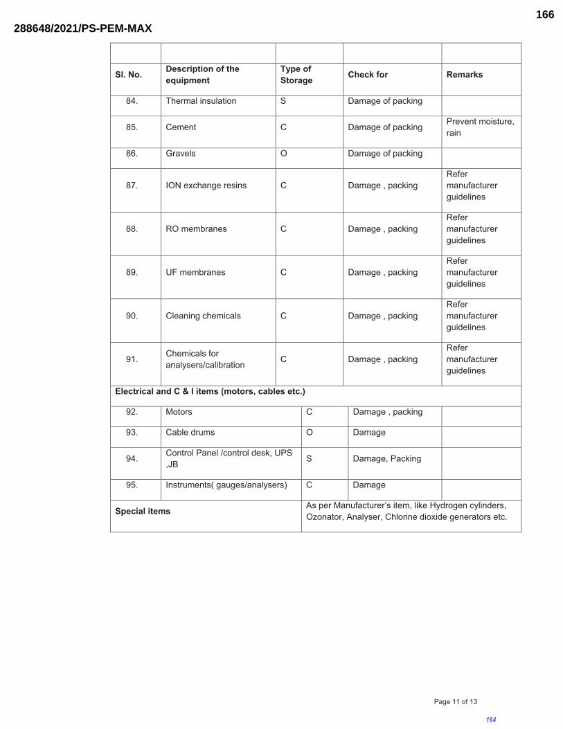
Sl. No. Description of the equipment
Type of Storage Check for Remarks
84. Thermal insulation S Damage of packing
85. Cement C Damage of packing Prevent moisture,
rain
86. Gravels O Damage of packing
87. ION exchange resins C Damage , packing
Refer
manufacturer
guidelines
88. RO membranes C Damage , packing
Refer
manufacturer
guidelines
89. UF membranes C Damage , packing
Refer
manufacturer
guidelines
90. Cleaning chemicals C Damage , packing
Refer
manufacturer
guidelines
91.Chemicals for
analysers/calibration C Damage , packing
Refer
manufacturer
guidelines
Electrical and C & I items (motors, cables etc.)
92. Motors C Damage , packing
93. Cable drums O Damage
94.Control Panel /control desk, UPS
,JB S Damage, Packing
95. Instruments( gauges/analysers) C Damage
Special items As per Manufacturer’s item, like Hydrogen cylinders,
Ozonator, Analyser, Chlorine dioxide generators etc.
Page 11 of 13
164
288648/2021/PS-PEM-MAX166

5. CONCLUSION
Concerned storage agency at site should make sure that loss in equipment performance
and wear & tear are minimised through proper storage and preservation. The above are
broad guidelines and cover major equipment / materials. However specific storage
practices shall be followed as per manufacturer recommendation. All the necessary
measures even in addition to the ones mentioned above, if found necessary, should be
taken to achieve the objective.
Page 12 of 13
165
288648/2021/PS-PEM-MAX167

Figure – 1 – PLATE STACKING ARRANGEMENT
Figure – 2 – STRUCTURAL STEEL STACKING ARRANGEMENT
Page 13 of 13
166
288648/2021/PS-PEM-MAX168

2X660 MW KHURJA STPP
TECHNICAL SPECIFICATION FOR ELEVATOR
SPECIFIC TECHNICAL REQUIREMENT -MECHANICAL
SPECIFICATION No: PE-TS-475-502-A001 SECTION IA REV. 00 APR 2021
ANNEXURE VIII – PACKING PROCEDURE
167
288648/2021/PS-PEM-MAX169

2X660 MW KHURJA STPP
TECHNICAL SPECIFICATION FOR ELEVATOR
SPECIFIC TECHNICAL REQUIREMENT -MECHANICAL
SPECIFICATION No: PE-TS-475-502-A001 SECTION IA REV. 00 APR 2021
ANNEXURE VIII – PACKING PROCEDURE
COMMON GUIDELINES FOR PACKING1. GENERAL:
The Components/Assemblies need to be packed suitably to avoid physical damage & corrosion during transit
& storage. This packing shall be suitable for different handling operations and for the adverse conditions
during transportation and during indoor / outdoor storage of materials.
All the equipment shall be suitably protected, coated, covered or boxed and crated to prevent damage or
deterioration during transit, handling and storage at site till the time of erection. The Contractor shall be
responsible for all loss or damage during transportation, handling and storage due to improper packing.
The identification marking indicating the name and address of the consignee shall be clearly marked in
indelible ink on two opposite sides and top of each of the packages. In addition the Contractor shall include
in the marking gross and net weight, outer dimension and cubic measurement.
Each package shall be accompanied by a packing note (in weather proof paper) quoting specifically the
name of the Contractor, the number and date of contract and names of the office placing the contract,
nomenclature of contents and Bill of Material.
2. TYPES OF PACKING: The following 5 types of packing have been standardized for packing of General Components/ Assemblies.
1) 'OP' - Open Type.
2) 'PP' - Partially Packed.
3) 'CP' – Crate/Box Packing - Components/Equipment requiring physical protection.
4) ‘CQ' - Case Packing – Machined components-Small & Medium Components/ Assemblies/ Equipment
which require corrosion & physical protection.
5) ‘CR’ - Case Packing – Electrical/Electronic Components/ Assemblies, which require special packing viz.
Water Proof, Shock Proof etc…
3. DESCRIPTION OF TYPES OF PACKING: The various types of packing, as standardized above, are described below.
3.1 'OP’ - Open Type In case, of components which are not affected by water & dust and do not require special protection, are
generally not machined, shall be sent as open packages. However, these components may be sent in crates,
wherever necessary.
3.2 'PP’ - Partially Packed Components which need special protection at selected portions only shall be despatched partially packed.
Machined surfaces should not be allowed to come directly in contact with the wood. Such surfaces should be
protected with 100GSM(Colourless) Multi Layered Cross Laminated Polyethylene
Film. All sharp corners and edges shall be protected by rubber mats to prevent damage to the polyethylene
film.
3.3 'CP’ - Crate Packing Assemblies/Components which need only physical protection from the point of view of handling shall be
despatched duly packed in crates.
3.4 ‘CQ’ - Case Packing - Machined Components/Assemblies/Equipment
168
288648/2021/PS-PEM-MAX170

2X660 MW KHURJA STPP
TECHNICAL SPECIFICATION FOR ELEVATOR
SPECIFIC TECHNICAL REQUIREMENT -MECHANICAL
SPECIFICATION No: PE-TS-475-502-A001 SECTION IA REV. 00 APR 2021
Small and medium sized components/assemblies/equipment due to size/weight and to avoid handling and
pilferage problems shall be packed in Case/Containers. Wherever required adequate quantity of silica gel or
VCI Powder/Tablets, packed in thin muslin cloth cotton bags shall be suitably placed. Small
machines/components of less weight shall be provided with suitable cushioning by Rubberised coir. The
components inside the case shall be entirely covered with100GSM(Colourless) Multi Layered Cross
Laminated Polyethylene Film, wherever required. This may be prescribed for electronic parts/critical
machined components/surfaces.
For mechanical product like valves where motors are separately securely wrapped in polyethylene, the
requirement of individual component wrapping shall be exempted.
3.5 'CR’ - Case Packing - Electrical & Electronic Components/Assemblies Delicate components likely to be damaged e.g. Gauges, Instruments etc. are to be wrapped in waxed paper or
polyethylene air bubble film and packed in cartons. Adequate quantity of Silica gel packed in cotton bags of
100grams each are to be suitably placed in the cartons. The cartons shall be entirely covered with
100GSM(Colourless) Multi Layered Cross Laminated Polyethylene Film before being packed in the cases.
VCI Powder/Tablets can be used as an alternative to Silica Gel.
Empty space in the cartons shall be filled with rubberized coir to get proper cushioning effect. The cartons
shall be manufactured from corrugated Fiber Board.
4 PREPARATION OF PACKING CASES 4.1 DIMENSIONS:
a) Thickness of planks for Front, rear, top and bottom sides and binding, jointing battens shall be 25/20mm
+2/-3 mm as per applicable drawings of the respective units.
b) Width of all planks including the tongue shall be more than 125mm and after plaining it shall be
minimum 100mm.
c) Minimum number of planks shall be used for a shook.
d) Horizontal, vertical, diagonal planks shall be given for binding (number of such planks depend on the
dimension of panel.
e) Width of binding planks shall be minimum 100mm.
f) Distance between any 2 binding planks shall be less than 750mm.
g) diagonal planks shall be used in between vertical binding planks when distance between inner to inner
of vertical planks is more than 750mm
h) Distance of the outer edges of these planks from the edge of case shall be less than 250mm.
i) Diagonal planks are not required for top planks and width side, if the width of pallet is less than 750mm.
4.2 JOINTING OF PLANKS Single length planks shall be used for cubicles whose overall length is less than 2400mm. For cubicles of
length more than 2400mm, jointing is permitted. The jointing shall be done with one single or maximum of 2
planks of wood same as other planks of width 250 mm (minimum) with two rows of nails on either side of
the joint in zigzag manner. From the joint along height side, it shall be of lap joint with overlap of at least the
width of plank.
4.3 TONGUE AND GROOVE JOINTS Two consecutive planks shall be joined by tongue and groove joint. Depth of tongue shall be 12+1 mm,
thickness of tongue shall be 8 +1 mm. The groove dimensions shall be such that the tongue fits tightly into
the groove to make a good joint. This type of joint can be done based on the product requirement wherever
required.
4.4 PERMISSIBLE DEFECTS Wood shall be free from knots, bows, visible sign of infection and any kind of decay caused by insects,
fungus, etc.
End splits: Longest end splits at each end shall be measured and lengths added together. The added length
169
288648/2021/PS-PEM-MAX171

2X660 MW KHURJA STPP
TECHNICAL SPECIFICATION FOR ELEVATOR
SPECIFIC TECHNICAL REQUIREMENT -MECHANICAL
SPECIFICATION No: PE-TS-475-502-A001 SECTION IA REV. 00 APR 2021
shall not exceed 60mm per meter run of shook’s. Wood pins shall be used to prevent further development
of split.
Surface cracks: Surface cracks with a maximum depth of 3mm are permissible. A continuous crack of any
depth all along the length is not allowed.
4.5 OTHER MATERIALS
4.5.1 NAILS The dia. of the nails shall be 3.15mm. The length of the nails shall be 65mm wherever two planks of 25mm
thickness are joined and 75mm wherever a 25mm planks is joined to a 50mm plank.
4.5.2 BLUE NAILS These are used for nailing bituminized Kraft paper/hessian cloth to the planks. The length of the nails shall
be 16mm.
4.5.3 HOOP IRON STRIPS These are used for strapping the boxes. The width of the strips shall be 19+1mm and thickness 0.6+0.01mm.
The material shall be free from rust.If sufficient nailing is done for bigger boxes, strapping need not be done.
4.5.4 CLIPS These shall be used for strapping the hoop iron strips on the boxes.
4.5.5 BRACKETS These brackets are used for nailing to the corners of cubicle boxes. The brackets shall be of mild steel of
thickness min 2mm and width 25+1mm. The brackets shall be of “L" shape, the length of each side being
100+2mm. Two holes shall be provided towards the end of each side for screwing /nailing.
4.5.6 FASTENERS Bolts, double nuts, spring washers will have to be used for packing of some special items like transformers,
reactors, breakers, etc., to hold the job to the bottom plank of the box. The bolts, nuts, washers will be
provided by the vendor. Drilling of holes will have to be done using contractor's tools.
4.5.7 MULTI LAYERED CROSS LAMINATED POLYTHELENE FILM 100GSM (Colourless) Multi Layered Cross Laminated Polythelene Film are used to make covers to the jobs
individually. The cross lamination gives qualities of extra toughness, together with flexibility and lightness
coupled with good weather resistance to ultra violet rays.
4.5.8 RUBBERISED COIR: The rubberized coir is used as cushioning material. For the packing of loose items, items are to be arrested
by using rubberized coir. For the packing of cubicles rubberized coir of thickness 25mm and width 75mm
shall be used.
4.5.9 FOAM RUBBER / 'U' FOAM: This is used for covering the delicate items. This material is provided by the vendor.
4.5.10 MARKING PLATE: This shall be of anodized aluminium sheet. Size of the marking plate shall be maintained minimum of size as
per the details specified in the Figure 4.
4.5.11 PACKING SLIP HOLDER: This shall be of galvanized iron tinned sheet /Aluminium sheet
4.5.12 SILICA GEL: Silical gel shall be used for such products only where moisture needs to be avoided.
4.5.13 COTTON BAGS:
170
288648/2021/PS-PEM-MAX172

2X660 MW KHURJA STPP
TECHNICAL SPECIFICATION FOR ELEVATOR
SPECIFIC TECHNICAL REQUIREMENT -MECHANICAL
SPECIFICATION No: PE-TS-475-502-A001 SECTION IA REV. 00 APR 2021
These are used for holding silica gel. The bags shall have the following matter indicated on them:
------------------------------------------------------------------------------------------------------------------------- -----
BHEL-UNIT NAME PLACE -PINCODE
SILICA GEL -INDICATING TYPE
BLUE : -ACTIVE
ROSE : -REDUCED ACTIVITY
WHITE : -NO ACTIVITY. TO BE REPLACED WITH FRESH SILICA GEL
--------------------------------------------------------------------------------------------------------------------------- -----
4.5.14 COTTON/ PLASTIC TAPE: This is used for tying small items. And also to prevent vibrations of moving parts within the cubicles.
4.5.15 MARKING INK: The ink used normally is black in color. In some special cases other color also will have to be used. The ink
shall be non-fading/indelible and non-washable by water.
4.5.16 POLYETHYLENE BAGS: These are to be used for keeping the Packing slips. The bag shall be of size 70mm X 100mm (minimum).
4.5.17 Hessian cloth, twine thread, paint will have to be used in packing certain items.
4.5.18 Mechanical Latching clamps: For CLW Railway panels and similar Panels self-locking clamps can also be used on need basis in
conjunction with or apart from regular bolt and nut fixing arrangement. For reusable boxes, these clamps
provide easy locking and unlocking arrangement. These clamps will be made available from BHEL in some
cases.
4.5.19 STICKERS The following stickers to be put by the vendor on cubicles/Boxes after packing.
1) Case No sticker: 2 nos. Size 25.Cm x 0.45Cm
2) BHEL Monogram sticker: 1 no. Size 1.75Cm x 2.3Cm
3) Address sticker: 2 nos. Size 3.8Cm x 3.0Cm
4) Direction sticker “Front” & “Back” - 4 nos. Size 2.0Cm x 0.75Cm
5) Chain Mark Sticker: 4 Nos. Size – 3.0Cm x 0.75Cm
6) "Fragile” sticker: 2 Nos. Size. 2.1Cm x 1.5Cm
7) "DO NOT STACK” sticker - 2 Nos. Size 3.0Cm x 2.2Cm
In place of stickers, writing all the details legibly with paint shall be allowed & respective units may take
decision accordingly.
5. PACKING OF CUBICLES: 5.1 The packing is to be done as per clause 4 in all respects.
5.2 The cubicles are already fixed on wooden pallets. Hence the contractor need not arrange the bottom pallets
normally.
5.3 The cubicles will be of different sizes both width wise and lengthwise. The cubicles may be made up of
single suite, 2 Suite, 3 Suite, 4 Suite, etc., The width of the cubicles generally varies from 400 mm to
1650mm.The length of the cubicle, generally varies from 1500 mm to 4800 mm. The height is normally
2430 mm. In some cases, the height may be less/more.
5.4 MULTI LAYER CROSS LAMINATED POLY FILM The inner surface of 4 sides of shook's shall be nailed with Multi-layer cross laminated poly film (as per
171
288648/2021/PS-PEM-MAX173

2X660 MW KHURJA STPP
TECHNICAL SPECIFICATION FOR ELEVATOR
SPECIFIC TECHNICAL REQUIREMENT -MECHANICAL
SPECIFICATION No: PE-TS-475-502-A001 SECTION IA REV. 00 APR 2021
4.5.7) using blue nails (as per 4.5.2) wherever 2 pieces of Cross laminated poly film are used, the joint shall
have an overlap of minimum 20mm.
The inner surface of top cover shall be nailed with Multi-layer cross laminated poly film (as per 4.5.7). This
sheet shall project outside on 4 sides by at least 100mm and shall be nailed properly on sides. Joining of
sheets should have overlap of minimum 20mm.
The cubicles shall be covered with Multi-layer cross laminated poly film (as per 4.5.7).
5.5 SILICA GEL: Silica gel (as per 4.5.12) packed in cotton bags shall be kept at different places inside the cubicle as per
BHEL-Unit directions. Each suit of cubicle shall be provided with 1 kg of Silica gel (for a 4 suit cubicle 4
kgs of Silica Gel to be used. The bag containing silica gel to be as per 4.5.13).
5.6 LOOSE PARTS:Any loose parts in the cubicles shall be tied using cotton/ plastic tape. Wooden battens shall be provided
wherever necessary.
5.7 WOODEN BATTENS: In case of cubicle which are not rectangular in shape like control desks, sufficient number of wooden
rafters/battens of proper size shall be provided to give strength to the package.
5.8 RUBBERISED COIR: Gap between the cubicle and the case shall be filled with rubberized coir (as per 5.5.8) with distance between
consecutive layers less than 500mm.
5.9 CLAMPING: Packing shall be bound at edges by nailing M.S. Clamps / Brackets (as per 5.5.5). Each vertical edge shall
have minimum 3 clamps. Top horizontal edges will have one clamp for every meter length of package.
However, minimum 4 clamps shall be nailed at the top for any cubicle.
5.10 PACKING SLIP: Packing slip kept in the polyethylene bag (As per 5.5.16) shall be placed in the box at appropriate place. In
addition, one more packing slip covered in polyethylene cover and packing slip holder (as per 5.5.11) shall
be nailed to front / rear of case.
5.11 MARKING PLATE: One no. (As per 5.5.10) shall be nailed to the front side of the case.
5.12 CASE MOUNTING: After complete packing, stencil marking of various details and marking of symbols shall be done as per
BHEL instructions using indelible / non washable marking ink.
5.13 Different types (Typical) of Cubicles with sizes for Packing 1. Single suite cubicle - 900 x 950 x2500
2. Two suite cubicle - 1650 x 950 x 2500
3. Three suite cubicle - 2400 x 950 x2500
4. Four suite cubicle - 3150 x 950 x 2500
5. Regulation cub - 1300 x 1350 x 2500
6. Thy cub - 2870 x 1350 x 2500
7. VFD Cub - 3800 x 1550 x 2500
6 PACKING OF LOOSE ITEMS/SPARES 1) Shape of cases shall be square, rectangular with single gabled roof or with double gabled roof depending
on the nature of the job to be packed. Construction shall be as per drawings enclosed. Only gable will be
172
288648/2021/PS-PEM-MAX174

2X660 MW KHURJA STPP
TECHNICAL SPECIFICATION FOR ELEVATOR
SPECIFIC TECHNICAL REQUIREMENT -MECHANICAL
SPECIFICATION No: PE-TS-475-502-A001 SECTION IA REV. 00 APR 2021
additional as required.
2) Wood with Tongue and Groove joint as per clause 4.3.
3) Width of planks shall be at least 100 mm. Width of binding planks (battens) shall be at least 75mm.
4) External surface of planks on front and rear shall be plane 100% (except bottom plank).
5) Inner surfaces of all 6 sides shall be lined with Multi Layered Cross Laminated Polythelene Film (as per
clause 4.5.7) using blue nails.
6) Rubberized coir of minimum 25mm thickness and 100 mm width shall be nailed to inner surfaces of
bottom and 4 sides of box.
7) Internal packing: Items that go into the box shall be packed using 100GSM, (Colourless) Multi Layered
Cross Laminated Polyethylene Film. Any space left between the job and the sides and the top of the box
shall be filled with rubberized coir to get proper cushioning effect.
8) Certain items like transformers, reactors, breakers, etc., shall be bolted to the bottom of the box using
bolts, nuts and washers.
9) Silica gel as per clause 4.5.12 held in cotton bags as per clause 4.5.13 shall be kept at proper places in the
box.
10) Packing slip kept in polyethylene bag (clause 4.5.16) shall be placed in the box.
11) Marking plate as per clause 4.5.10 shall be nailed to side of the box.
12) Two numbers of hoop iron strips as per clause 4.5.3 shall be strapped tightly on the case using clips.
13) Stencil marking of various details and marking of various symbols shall be done as per BHEL
instructions using indelible/non-washable marking ink.
14) Loose items to be kept inside the cubicle
- The components which are removed from cubicle for shipping purpose only, such as meters shall be kept
inside the cubicle individually, kept in wooden box and tied firmly in bottom of Cubicle.
- Other items which are given loose in addition to cubicle shall be packed in separate boxes.
7 BOX SIZES
7.1 BOX SIZES Table 1 – SPARES WOODEN BOX DETAILS
SNO BOX BOX SIZE BOX Wt Carrying
Capacity TYPE (in mm) (in KG)
1 A 800 X 200 X 200 15
2 B 1500 X 200 X 200 22
3 C 2000 X 200 X 200 27
4 D 1100 X 200 X 200 15
5 E 200 X 200 X 200 5
6 F 320 X 250 X 260 13
7 G 320 X 250 X 430 16
8 H 430 X 370 X 430 23
9 I 1100 X 400 X 400 45
10 J 1500 X 500 X 400 65
11 K 2000 X 500 X 400 93
173
288648/2021/PS-PEM-MAX175

2X660 MW KHURJA STPP
TECHNICAL SPECIFICATION FOR ELEVATOR
SPECIFIC TECHNICAL REQUIREMENT -MECHANICAL
SPECIFICATION No: PE-TS-475-502-A001 SECTION IA REV. 00 APR 2021
12 L 2500 X 500 X 400 88
13 M 900 X 600 X 600 100
14 N 3000 X 400 X 400 60
15 P 600 X 500 X 400 35
16 Q 710 X 630 X 600 90
17 R 850 X 630 X 670 102
18 S 1000 X 770 X 670 140
19 T 2500 X 850 X 800 180
20 U 1500 X 700 X 700 120
21 W 1200X900X600 120
22 Y 450 X 200 X 200 10
Table 2 – WOODEN BOX DETAILS
BOX TYPE BOX SIZE (in MM) BOX Wt (in
KG) Carrying Capacity
1 320X250X260 10
2 320X250X430 15
3 430X370X430 25
4 670X670X470 65
5 720X630X600 75
6 1000X770X660 100
7 1100X430X670 80
8 1200X1200X900 80
9 1300X770X1050 155
10 2500X850X800 225
11 2000X1500X1200 305
12 1850X1050X1250 260
13 2000X800X800 180
14 2600X1500X1600 470
15 250X250X600 20
16 250X250X880 30
17 300X300X700 25
18 380X380X880 45
19 510X510X1400 60
20 570X570X1400 80
21 575X575X1875 105
22 3600X1100X1100 390
23 900X500X800 110
24 2000X950X740 225
174
288648/2021/PS-PEM-MAX176

2X660 MW KHURJA STPP
TECHNICAL SPECIFICATION FOR ELEVATOR
SPECIFIC TECHNICAL REQUIREMENT -MECHANICAL
SPECIFICATION No: PE-TS-475-502-A001 SECTION IA REV. 00 APR 2021
25 1600X1120X700 220
26 2500X2000X1200 490
27 2900X1900X1400 525
28 3000X1000X900 370
29 3200X2200X950 450
30 2150X1100X750 325
31 2000X2000X700 130
32 700X1200X1325 130
TABLE 3 STEEL BOXES
TYPE
DIMENSION IN MM
WEIGHT CARRYING CAPACITY
(KGS) S.NO. LENGTH BREADTH HEIGHT
1 I 2480 1680 1500 339 4500
2 II 1200 900 600 61 2000
3 IIB 1800 850 950 115 2500
4 III 900 600 600 29 1000
5 IV 600 450 500 19 750
6 V 400 350 300 11 500
TYPICAL PATTERN OF WOODEN BOX
175
288648/2021/PS-PEM-MAX177

2X660 MW KHURJA STPP
TECHNICAL SPECIFICATION FOR ELEVATOR
SPECIFIC TECHNICAL REQUIREMENT -MECHANICAL
SPECIFICATION No: PE-TS-475-502-A001 SECTION IA REV. 00 APR 2021
7.3 SEALED PACKING: Components sub-assemblies and assemblies sensitive to climatic conditions shall be packed seal tight. All
the openings of the sensitive components, sub-assemblies and assemblies shall be blanketed to prevent the
ingress of dust and moisture. The components sub-assemblies and assemblies are completely covered with 2
layers of polyethylene sheet. All sharp corners and edges are to be protected by rubber mats to prevent the
polyethylene sheet from damage. Top surface of the case shall be free from dents to prevent rain water
pockets.
8 MARKINGS/STENCILINGS
176
288648/2021/PS-PEM-MAX178

2X660 MW KHURJA STPP
TECHNICAL SPECIFICATION FOR ELEVATOR
SPECIFIC TECHNICAL REQUIREMENT -MECHANICAL
SPECIFICATION No: PE-TS-475-502-A001 SECTION IA REV. 00 APR 2021
Black and Red Marking Ink to IS:1234 "Ink, Stencil, Oil Base, For Marking Porous Surfaces" or duplicating
ink stencilling, oil base for marking porous surfaces.
All cases containing fragile items are to be stencilled with red marking and stencilling paint/ink
"HANDLE WITH CARE", "FRAGILE DO NOT TURN OVER". Besides the caution signs the product information’s shall be stencilled of letters with 13mm to 50mm height.
In case of consignment consists of more than one package, each package shall carry its package no as given
in shipping list. All caution signs shall be stencilled in high quality full glossy out door finishing paint red in
colour (AA56126). All other markings shall be carried out in black enamel.
Caution signs & other markings shall be stencilled on both the end shooks & the side shooks.
Caution sign (for slinging) shall be stencilled only on side shooks at the appropriate place.
Note: Incase the size of package is small for using the stencils, then hand written letters/figures shall be
allowed.
177
288648/2021/PS-PEM-MAX179

2X660 MW KHURJA STPP
TECHNICAL SPECIFICATION FOR ELEVATOR
SPECIFIC TECHNICAL REQUIREMENT -MECHANICAL
SPECIFICATION No: PE-TS-475-502-A001 SECTION IA REV. 00 APR 2021
9 STANDARD METHOD OF PACKING Table 5 - Standard Method of Packing
DESCRIPTION CASE CRATE SKID BUNDLE BARE DRUM METAL
DRUM FIBRE DRUM
PRESSUE VESSELS
TOWERS O
TANKS O
178
288648/2021/PS-PEM-MAX180

2X660 MW KHURJA STPP
TECHNICAL SPECIFICATION FOR ELEVATOR
SPECIFIC TECHNICAL REQUIREMENT -MECHANICAL
SPECIFICATION No: PE-TS-475-502-A001 SECTION IA REV. 00 APR 2021
VESSELS O
GASKETS O
FASTENERS O
COVERS O
EXCHANGERS
HEAT EXCHANGERS O
TUBE BUNDLE O
SHELL O
AIR FIN COOLERS O
COLOUMNS, MOTOR SUSPENSIONS, PLENUM CHAMBERS, SCREEN GUARDS, ETC
O
BEARING BLOCKS O
FANS O O
MOTORS O
GASKETS O
FASTENERS O
TEST FLANGES O
TEST RINGS O
COVERS O
CRYOGENIC VESSELS
COLD CONVERTERS O
HORIZONTAL STORAGE TANKS O
TRANSPORTATION TANK O
COLD BOX O
DRYING UNIT O
DRYING BOTTLES O
MOISTURE SEPARATORS O
SILENCERS O
ONGC SKIDS O
VAPORISER O
SPECIAL PRODUCTS
SI/VI PIPING O
CRO BIO CONTAINERS O
DESCRIPTION CASE CRATE SKID BUNDLE BARE DRUM METAL
DRUM FIBRE DRUM
AIR BOTTLES O
TITANIUM BOTTLE O
WAR HEAD CONTAINER O
MISSILE CONTAINER O
FUEL CONTAINER O
AIR LOCK ASSEMBLY O
BOILER DRUMS O
179
288648/2021/PS-PEM-MAX181

2X660 MW KHURJA STPP
TECHNICAL SPECIFICATION FOR ELEVATOR
SPECIFIC TECHNICAL REQUIREMENT -MECHANICAL
SPECIFICATION No: PE-TS-475-502-A001 SECTION IA REV. 00 APR 2021
BOILER ITEMS
COILS O
PANELS O
HEADERS O O
FEEDERS
MACHINED ITEMS
SHELL SEGMENTS O
SHELL SEGMENTS IN STACKS O
SPHERE PETALS
COLOUMNS, BASE PLATES, TIERCOS, PIPES, NOZZLE E1, F1, INTERNAL PIPES, PADS ETC.
O
ROLLERS O
VALVE TRAYS
VALVE TRAY COMPONENTS O
LATTICE GIRDERS O
FASTENERS O
GASKETS O
SUB CONTRACTS
FAB STRUCTURALS O
SUPPORTING STRUCTURALS O
STRUCTURE SUB ASSEMBLY O
FAB PIPES O
GRATINGS O
STAIR CASES O
HANDRAILS/ PLATFORMS O
BOUGHT OUT COMPONENTS
IRON & STEEL (LIKE PLATES, BEAMS, ANGLES, CHANNELS ETC.) O
PIPE FITTINGS
CS PIPES, TUBES O
SS PIPES, TUBES O
FIN TUBES O
ELBOWS O O
DESCRIPTION CASE CRATE SKID BUNDLE BARE DRUM METAL
DRUM FIBRE DRUM
FLANGES O O
VALVES O
GAUGES O
DEMISTERS O
ABSCRBANTS (LIKE MOLECULAR SIEVES, ACTIVATED ALUMINA, MOBILE SORBID)
O
PAINT TINS O
180
288648/2021/PS-PEM-MAX182

2X660 MW KHURJA STPP
TECHNICAL SPECIFICATION FOR ELEVATOR
SPECIFIC TECHNICAL REQUIREMENT -MECHANICAL
SPECIFICATION No: PE-TS-475-502-A001 SECTION IA REV. 00 APR 2021
PAINT DRUMS O
IGNITORS O
SPRAY NOZZLES O
ELECTRICAL INSTRUMENTATION
MOTORS, PUMPS, COMPRESSORS, TURBINES O
SWITCH BOARDS, DISTRIBUTION BOARDS, STARTERS, JUNCTION BOXES O
INDICATORS, VIBRATOR SWITCHES O
CABLE BUNDLES, CABLE DRUMS O CABLE TRAYS, CABLE RACKS, EARTHING MATERIAL O
OPERATIONAL SPARES O
10 PROCEDURE FOR HANDLING OF COMPONENTS The purpose of this procedure is to protect the quality of the components/equipment while handling in various
stages of manufacturing packing & despatching.
10.1 Adequate care shall be taken in handling the material, and components to avoid damage during receipts,
storage issue manufacture & despatch operations.
10.2 Appropriate material handling equipment like fork lifters, cranes etc. shall be used where needed.
10.3 Lifting by crane and transportation by trolley of critical items and large components like rotors castings
etc. shall be done carefully.
10.4 For critical items, where specified, special handling fixtures shall be used for lifting.
10.5 Slings and shackles used for lifting the components/equipment shall be checked for fitness and
suitability before use.
10.6 Slings used on machined surfaces shall be suitably padded. No slings shall be used on journal surfaces.
10.7 Precision machined components like blades, catches, rollers etc. shall be lifted using suitable wooden
pallets.
10.8 HANDLING OF COMPONENTS ON RECEIPT/DESPATCHBefore loading/unloading a packing case from the carrier look for the following shipping instructions painted
on the packing case.
a) The markings showing the upright position.
b) The markings showing the sling position
c) Markings showing the fragile contents.
d) Other required markings as per clause no.10
181
288648/2021/PS-PEM-MAX183

2X660 MW KHURJA STPP
TECHNICAL SPECIFICATION FOR ELEVATOR
SPECIFIC TECHNICAL REQUIREMENT -MECHANICAL
SPECIFICATION No: PE-TS-475-502-A001 SECTION IA REV. 00 APR 2021
10.8.1 Appropriate cranes and slings should be used for different components/ cases. Slings should normally
make an angle as minimum as possible (width wise) but in no case more than 15º.
10.8.2 Handling and lifting should be done without jerks or impacts.
10.8.3 Immediately after receipt of the goods, the packing should be examined all-round for any sign of damage.
If necessary, lift the cover or a number of boards of the case so as to make the contents visible. In the
event of sealed packing being used the plastic sheeting should not be damaged. It is imperative that the
packing material is restored in original condition after the inspection.
10.8.4 On receipt of the equipment it should be checked with the shipping list and missing or damage if any
should be reported immediately. It is important to arrange for immediate examination to determine the
extent of the damage, the cause of the damage and where applicable the person or persons responsible
for the damage. According to general practice when transporting by railway or by road vehicle the
carrier concerned should be immediately called upon (within specified periods) for jointly establishing
a statement of the damage. This is essential as a basis for a subsequent claim and possible damage
report to the insurance company.
10.8.5 Protective coating applied on machined surfaces should not be disturbed. The plastic covering should be
put back carefully so that it prevents ingress of dust and moisture. Some packing may have vapour
phase inhibitor (VPI) paper enclosed inside the packing cases. This should be restored to its original
place as far as possible.
10.8.6 Silica gel and such other chemicals kept in the box as desiccants and indicators should also be left in the
box itself.
11 GENERAL GUIDELINES FOR ODC TRANSPORTATION/DESPATCH Based on the Dimensions/Weight indicated in the Transportation Sketch, the type of Trailer is decided and
indicated in the Tender Enquiry.
11.1 TRANSPORTATION: 1. LOW BED TRAILERS (LB 8):
Well Bed Length : 10000mm
Over Gooseneck : 13000mm
Width : 3000mm
Carrying Capacity : 40MT
2. LOW BED TRAILERS (LB 16):
Well Bed Length : 12000mm
Over Gooseneck : 16000mm
Width : 3000mm
Carrying Capacity : 75MT
3. TOW TYPE TRAILERS (WITH FRONT DOLLEY 16 TYRES): 12000MM length
(for Exceptional equipment length: 30000mm and above)
Bigger Dia equipment are loaded in the Well with overhanging.
Smaller Dia equipment with excess length are loaded over Gooseneck with rear hanging.
The Vehicle Dimensions are defined above are only guidelines for selection based on actual Dimensions/
Weight of the Consignment
182
288648/2021/PS-PEM-MAX184

2X660 MW KHURJA STPP
TECHNICAL SPECIFICATION FOR ELEVATOR
SPECIFIC TECHNICAL REQUIREMENT -MECHANICAL
SPECIFICATION No: PE-TS-475-502-A001 SECTION IA REV. 00 APR 2021
11.2 PACKING: For all ODCs, Wooden Saddles are cut to the diameter of equipment as per the Transportation Sketch.
For Securing the equipment firmly on the Trailer, 19mm (3/4”), wire rope with 25mm (1”) Heavy Duty
Turn Buckles / BD Clamps are used as Lashing for the equipment.
12 GUIDELINES FOR HANDLING/LOADING/LASHING
� Jobs to be checked for complete painting before loading.
� Components to be lifted with Nylon belts. This protects painting, edges and attachments.
� All the components to be transported by putting inside the properly fabricated Crating
� Small components may fall down while transporting without closed crating and there are chances of
missing of small parts. Hence, it is always better to transport small components in closed
containers/crating. Loose to be being shipped in a closed crating.
� No component loaded over the crating.
� LASHING: Use Nylon belts only for lashing of all components. It prevents removal off painting and cut
in the materials.
183
288648/2021/PS-PEM-MAX185

2X660 MW KHURJA STPP
TECHNICAL SPECIFICATION FOR ELEVATOR
SPECIFIC TECHNICAL REQUIREMENT -MECHANICAL
SPECIFICATION No: PE-TS-475-502-A001 VOL IIB SECTION IA REV. 00 APR 2021
ANNEXURE-IX
CIVIL INPUT DETAILS (Refer attached civil input assignment drawings.)
184
288648/2021/PS-PEM-MAX186
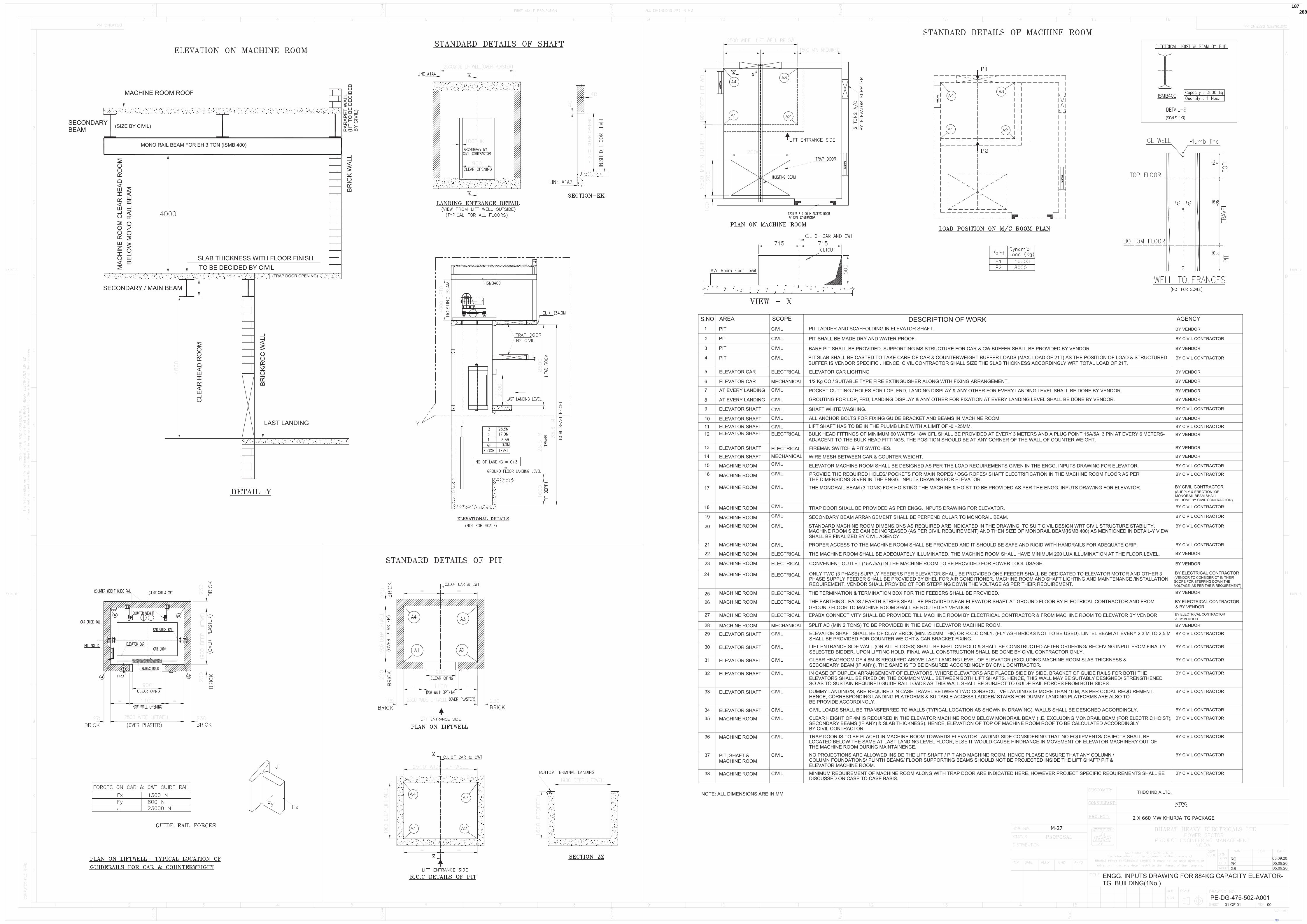
185
288648/2021/PS-PEM-MAX187

186
288648/2021/PS-PEM-MAX188

2X660 MW KHURJA STPP
TECHNICAL SPECIFICATION FOR ELEVATOR
SPECIFIC TECHNICAL REQUIREMENT -ELECTRICAL
SPECIFICATION No: PE-TS-475-502-A001 SECTION IB REV. 00 APR 2021
SECTION – IB
SPECIFIC TECHNICAL REQUIREMENT-ELECTRICAL
187
288648/2021/PS-PEM-MAX189

TITLE :
ELECTRICAL EQUIPMENT SPECIFICATION FOR
ELEVATOR2X660MW KHURJA TG
SPECIFICATION NO.
VOLUME NO. : II-BSECTION : CREV NO. : 00 DATE : 22.03.2021 SHEET : 1 OF 2
1.0 EQUIPMENT & SERVICES TO BE PROVIDED BY BIDDER:
a) Services and equipment as per “Electrical Scope between BHEL and Vendor”.
b) Any item/work either supply of equipment or erection material which have not
been specifically mentioned but are necessary to complete the work for trouble free
and efficient operation of the plant shall be deemed to be included within the scope
of this specification. The same shall be provided by the bidder without any extra
charge.
c) Supply of mandatory spares as specified in the specifications of mechanical
equipments.
d) Electrical load requirement for ELEVATOR in load data format.
e) All equipment shall be suitable for the power supply fault levels and other climatic
conditions mentioned in the enclosed project information.
f) Bidder to furnish list of makes for each equipment at contract stage, which shall be
subject to customer/BHEL approval without any commercial and delivery
implications to BHEL
g) Various drawings, data sheets as per required format, Quality plans, calculations,
test reports, test certificates, operation and maintenance manuals etc shall be
furnished as specified at contract stage. All documents shall be subject to
customer/BHEL approval without any commercial implication to BHEL.
h) Motor shall meet minimum requirement of motor specification.
i) Vendor to clearly indicate equipment locations and local routing lengths in their
cable listing furnished to BHEL.
j) Cable BOQ worked out based on routing of cable listing provided by the vendor
for “ both end equipment in vendor’s scope”shall be binding to the vendor with
+10 % margin to take care of slight variation in routing length & wastages.
2.0 EQUIPMENT & SERVICES TO BE PROVIDED BY PURCHASER FOR
ELECTRICAL & TERMINAL POINTS:
Refer “Electrical Scope between BHEL and Vendor”.
3.0 DOCUMENTS TO BE SUBMITTED ALONG WITH BID
3.1 The electrical specification without any deviation from the technical/quality assurance
requirements stipulated shall be deemed to be complied by the bidder in case bidder
furnishes the overall compliance of package technical specification in the form of
compliance certificate/No deviation certificate.
3.2 No technical submittal such as copies of data sheets, drawings, write-up, quality plans,
type test certificates, technical literature, etc, is required during tender stage. Any such
submission even if made, shall not be considered as part of offer.
188
288648/2021/PS-PEM-MAX190
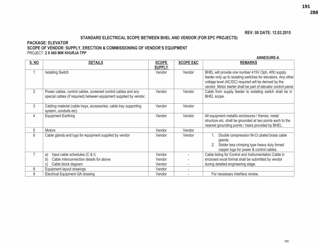
��������������� �� �����
��������������������������������������������������������������������������������������������� ���!"���������#���$$�������������������%���& ��$���PROJECT: ��'�((��$���� ����� �
� � � � � � � � � � � � � � � � ���' ��)�� ���� ������ ������
� ���!���������#��
���$����
1 Isolating Switch Vendor Vendor� BHEL will provide one number 415V (3ph, 4W) supply feeder only up to isolating switches for elevators. Any other voltage level (AC/DC) required will be derived by the vendor. Motor starter shall be part of elevator control panel.
2 Power cables, control cables, screened control cables and any special cables (if required) between equipment supplied by vendor.
Vendor Vendor Cable from supply feeder to isolating switch shall be in BHEL scope.
3 Cabling material (cable trays, accessories, cable tray supporting system, conduits etc).
Vendor Vendor
4 Equipment Earthing Vendor Vendor All equipment metallic enclosures / frames, metal structure etc. shall be grounded at two points each to the nearest grounding points / risers provided by BHEL.
5 Motors Vendor Vendor 6 Cable glands and lugs for equipment supplied by vendor Vendor Vendor 1.� Double compression Ni-Cr plated brass cable
glands 2.� Solder less crimping type heavy duty tinned
copper lugs for power & control cables. 7 a)� Input cable schedules (C & I)
b)� Cable interconnection details for above c) Cable block diagram
Vendor Vendor Vendor
---
Cable listing for Control and Instrumentation Cable in enclosed excel format shall be submitted by vendor during detailed engineering stage.
8 Equipment layout drawings Vendor - 9 Electrical Equipment GA drawing Vendor - For necessary interface review.
�
189
288648/2021/PS-PEM-MAX191

�
����� �
������
�������������� ����
������������������������
��������� � ������������������������������������������� ����������������������������� �����������������������������������������������������������������������������������������
�
� �
�
���� ��������!?���@�@�![�\�@]\�� � � ^� _��{������ ��|�!]!��}}�[@�?~�����\�@����{�����!{@{\�^� ����������� ���@�~~�@�{������{{\����]@�{{\��� � ^� ���\��]�\���
����� ��@��~��{���][[~�����@�!� ��� ��� ��@����{~@�������@����\��@�{���� ^� ��_��������� ?�� ��@����\��]��}�����@�����\��@�{��� ^� _���������������_���� }�� {!?������{~@�������\������\��@�{�� ^� ������]!�{���?�{~]@����~]����� ��� ���@�!���]~@�~���~��@�\�@����{~@���� ^� _������{\�����}��
��� ��{\@�@�!��\�@�����{\�@�\!���~��?{|��� �o� �����������][@{������� ^� _������{\�����}��
��\����\�}{�@\{~~����o� ��~{���������� � ^� �����@����?]�~@���|�����@@�����
� !����@�}� \�~����� �{\� ��{\@�}�\}]�@ �������~{�����@����[�\�@�����]�@�?~��{��\~{����������������\�~������~~�?��[\{�������
������� ��� ������@�!��\{]������� � ^� ����}@���~���\{]�������_��� ~����{�����]~�@�{�� � � � ^� ���\!�~�}~������{\�?�@@�\������� ����!]!��{~@�����{\��@�\@���� � � ^� �_��{��\�@����{~@�����{\�\�@����?�~{�����������
����[�\}��@����{��\�@����{~@����� � � ��������������{��\�@����{~@����{\�\�@���� �����������������������������������������������������������������������?�@�������������������
����� �{��\�}�?~�����@�� � � � ^� ���~~�?���������]\������@��~������������� ��\@��{��]}@{\����������@�\��~� � ^� ���~~�?���������]\������@��~������������� �[�}�����@�\��][[~�� � � � ^� ������������_������������ ��@����][�@{����}������~��[�����!{@{\� ^� �}}�[@�?~��?�~{����������������� ����@�{��~�@��@�� � � � ^� ���[�\��������}]�@{!�\�!{@{\��[�}�
� � � � � � � ������ ~�!��[\{{��!{@{\��
��� ��}~{�]\���]�@�?~������[�\���^������ ^� ���[�\�\��]�\�!��@�?�� ~������}�@�{��{������\�{]���\���� ^� ���[�\�\��]�\�!��@�
����[�\���^�__����[�\@�����
����� ������ ^� ���[�\�� ���������� ������ ����@������� ^� ����_������_����������\���{���\{@�}@�{��{����}~{�]\���!{@{\��^������������� ���������� ���_��� � ����������������������������__�������� ���\�������}���}�� ^�����������������[�\���^����_^������
190
288648/2021/PS-PEM-MAX192

�
����� �
������
�������������� ����
������������������������
��������� � ������������������������������������������� ����������������������������� �����������������������������������������������������������������������������������������
�
� �
�
��
�� ���������!��"#���$�%��*�+;�<�%�����%�����=��%�<�%%�������>+������?!�@��*�+;���
191
288648/2021/PS-PEM-MAX193

TITLE
MOTOR
DATA SHEET - C
SPECIFICATION NO. VOLUME II B SECTION D REV NO. 00 DATE 29/08/2005 SHEET 1 OF 2
NAME OF VENDOR SEAL
REV.
NAME SIGNATURE DATE
S. No.
Description Data to be filled by successful bidder
A. General
1 Manufacturer & country of origin
2 Motor type
3 Type of starting
4 Name of the equipment driven by motor & Quantity
5 Maximum Power requirement of driven equipment
6 Rated speed of Driven Equipment
7 Design ambient temperature
B. Design and Performance Data
1 Frame size & type designation
2 Type of duty
3 Rated Voltage
4 Permissible variation for
5 a Voltage
6 b Frequency
7 c) Combined voltage & frequency
8 Rated output at design ambient temp (by resistance method)
9 Synchronous speed & Rated slip
10 Minimum permissible starting voltage
11 Starting time in sec with mechanism coupled
12 a) At rated voltage
13 b) At min starting voltage
14 Locked rotor current as percentage of FLC (including IS tolerance)
15 Torque
a) Starting
b) Maximum
16 Permissible temp rise at rated output over ambient temp & method
17 Noise level at 1.0 m (dB
18 Amplitude of vibration
19 Efficiency & P.F. at rated voltage & frequency
a) At 100% load
c) At 75% load
Page 205 of 226
192
IB
288648/2021/PS-PEM-MAX194

TITLE
MOTOR
DATA SHEET - C
SPECIFICATION NO. VOLUME II B SECTION D REV NO. 00 DATE 29/08/2005 SHEET 2 OF 2
NAME OF VENDOR SEAL
REV.
NAME SIGNATURE DATE
S. No.
Description Data to be filled by successful bidder
c) At starting
C. Constructional Features
1 Method of connection of motor driven equipment
2 Applicable Standard
3 DOP of Enclosure
4 Method of cooling
5 Class of insulation
6 Main terminal box
a) Type
b) Power Cable details (Conductor, size, armour/unarmour)
c) Cable Gland & lugs details (Size, type & material)
d) Permissible Fault level ( kArms & duration in sec)
7 Space heater details (Voltage & watts)
8 Flame proof motor details (if applicable)
a) Enclosure
b) suitability for hazardous area
i Zone O / I / II
ii Group IIA / IIB / IIC
9 No. of Stator winding
10 Winding connection
11 Kind of rotor winding
12 Kind of bearings
13 Direction of rotation when viewed from NDE
14 Paint Shade & type
15 Net weight of motor
16 Outline mounting drawing No (To be enclosed as annexure)
D. Characteristic curves/ drawings (To be enclosed for motors of rating � 55KW)
a) Torque speed characteristic
b) Thermal withstand characteristic
c) Current vs time
d) Speed vs time
Page 206 of 226
193
IB
288648/2021/PS-PEM-MAX195

2X660 MW KHURJA STPP
TECHNICAL SPECIFICATION FOR ELEVATOR
SPECIFIC TECHNICAL REQUIREMENT -ELECTRICAL
SPECIFICATION No: PE-TS-475-502-A001 VOL IIB SECTION IB REV. 00 APR 2021
CUSTOMER SPECIFICATION FOR ELECTRICAL PART
1. ELEVATOR-(ELECTRICALS) 2. MOTORS 3. LT POWER CABLES 3. LT CONTROL CABLES 5. CABLING EARTHING LIGHTNING AND PROTECTION 6. LT SWITCHGEAR & LT BUSDUCT
194
288648/2021/PS-PEM-MAX196
KHURJA SUPER THERMAL POWER PROJECT (2X660 MW)
TURBINE GENERATOR AND ASSOCIATED PACKAGES BID DOC. NO.: THDC/RKSH/CC-9915-371
SEPARATOR
SUB–SECTION – B-10
ELEVATOR TG
195
(ELECTRICALS)
288648/2021/PS-PEM-MAX197

CLAUSE NO. TECHNICAL REQUIREMENTS
KHURJA SUPER THERMAL POWER PROJECT (2X660 MW)
TURBINE GENERATOR AND ASSOCIATED PACKAGES
TECHNICAL SPECIFICATION SECTION – VI, PART-B
BID DOC. NO.: THDC/RKSH/CC-9915-371
SUB-SECTION-B-10 ELEVATOR ELECTRICALS
PAGE 1 OF 2
ELEVATORS (ELECTRICALS)
1.00.00 CODES AND STANDARDS
1.01.00 All standards, specifications and codes of practice referred to herein shall be the latest editions including all applicable official amendments and revisions. In case of conflict between this specification and those (IS codes, standards, etc.) referred to herein, the former shall prevail. All work shall be carried out as per the following standards/ codes as applicable.
IS:4722, IS:325
2.00.00 Electric motor:
The driving motors shall conform to I.S 325 and suitable for the Variable Voltage Variable Frequency (VVVF) application. All motors shall be squirrel cage induction type, suitable for operation at 415V (+/- 10% variation) , 3 phase, 3 wire, 50HZ (+3% to -5% variation) supply. Motors shall be provided with thermal class 130 (B) or better insulation
3.00.00 CAR ELECTRICAL ACCESSORIES The following accessories shall be provided :
i) LED light fittings for illumination level of 100 lux on car floor.
ii) Portable light and alarm bell with battery and charger ventilation fan with control.
iii) Car control station with position indicator inside the car and at landing platforms ( both visual and audio).
iv) Emergency stop switch.
v) 5/15A ,3 pin plug socket with switch on top of lift car.
vi) Hand free speaker telephone set connected to plant network.
vii) AUTOMATIC RESCUE DEVICE (ARD)-(BATTERY DRIVE) :
Bidder to provide a modern Advanced electronic drive system of “RESCUING Passenger Trapped in a ELEVATOR”.
viii) EMERGENCY SAFETY DEVICES :
The lift shall be provided with safety Device attached to the lift car frame and placed beneath the car. The safety device shall be capable of stopping and sustaining the lift car up at governor tripping speed with full rated load in car.
4.00.00 OPERATIONAL REQUIRMENTS:
a. Bidder shall provide car operating panel with luminous buttons, car position indication in car (both visual and audio) combined with direction arrows, overload warning indicator, battery operated alarm bell and emergency light and fan & hands free speaker telephone set with suitable battery, charger & controls.
b. Bidder shall provide emergency indicator to indicate the location of elevator in case of elevator being stuck up between the floors through automatic flashers (both audio & visual).
196
288648/2021/PS-PEM-MAX198
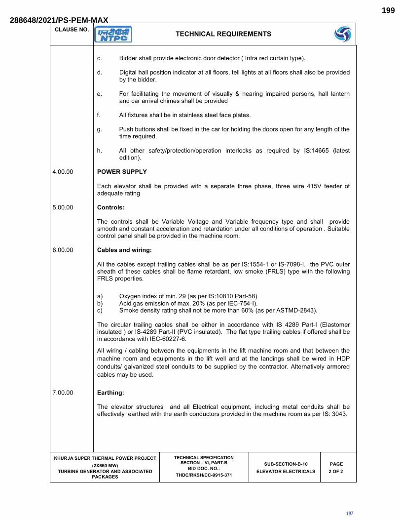
CLAUSE NO. TECHNICAL REQUIREMENTS
KHURJA SUPER THERMAL POWER PROJECT (2X660 MW)
TURBINE GENERATOR AND ASSOCIATED PACKAGES
TECHNICAL SPECIFICATION SECTION – VI, PART-B
BID DOC. NO.: THDC/RKSH/CC-9915-371
SUB-SECTION-B-10 ELEVATOR ELECTRICALS
PAGE 2 OF 2
c. Bidder shall provide electronic door detector ( Infra red curtain type).
d. Digital hall position indicator at all floors, tell lights at all floors shall also be provided by the bidder.
e. For facilitating the movement of visually & hearing impaired persons, hall lantern and car arrival chimes shall be provided
f. All fixtures shall be in stainless steel face plates.
g. Push buttons shall be fixed in the car for holding the doors open for any length of the time required.
h. All other safety/protection/operation interlocks as required by IS:14665 (latest edition).
4.00.00 POWER SUPPLY
Each elevator shall be provided with a separate three phase, three wire 415V feeder of adequate rating
5.00.00 Controls:
The controls shall be Variable Voltage and Variable frequency type and shall provide smooth and constant acceleration and retardation under all conditions of operation . Suitable control panel shall be provided in the machine room.
6.00.00 Cables and wiring:
All the cables except trailing cables shall be as per IS:1554-1 or IS-7098-I. the PVC outer sheath of these cables shall be flame retardant, low smoke (FRLS) type with the following FRLS properties.
a) Oxygen index of min. 29 (as per IS:10810 Part-58) b) Acid gas emission of max. 20% (as per IEC-754-I). c) Smoke density rating shall not be more than 60% (as per ASTMD-2843).
The circular trailing cables shall be either in accordance with IS 4289 Part-I (Elastomer insulated ) or IS-4289 Part-II (PVC insulated). The flat type trailing cables if offered shall be in accordance with IEC-60227-6.
All wiring / cabling between the equipments in the lift machine room and that between the
machine room and equipments in the lift well and at the landings shall be wired in HDP
conduits/ galvanized steel conduits to be supplied by the contractor. Alternatively armored
cables may be used.
7.00.00 Earthing:
The elevator structures and all Electrical equipment, including metal conduits shall be effectively earthed with the earth conductors provided in the machine room as per IS: 3043.
197
288648/2021/PS-PEM-MAX199

���������� ����������������� ���������
������������ ���������� �������������������� ���!���!��"##$%"'+$
����� ��
SUB–SECTION – B-2
�� ��
198
288648/2021/PS-PEM-MAX200

�������� ����������<�������
���������� ����������������� ���������
������������ ���������� ���������
������������>��� ����� ��� ?�@��� "�
����������� ���!���!��"##$%"'+$
��"�� ����"���� ��
����$ �>#
�� ��
$������ ���������<�������
�������� �� � �� ������� �� ������� �� ������������������� ��� �������� ������������ �� ��� �����������������������!���"�� ����������#�$�*���<�������?�� �!!����@����������[ ������������� �!!������������� �� !���!!�������"���������
�������� \!!������������ �!!����������!������������������@�������]^�_�� ���"����������`�$�{� |�$��������$�@�������"����������"!����������������@����!�������@���@�!!������ ��������� �����@���@�����
�������� �����@��� � �!!� ��"���� ��!!�� @������!�� �!�@���@�!� �������� ����������� �@@�������� �������"�@���
���<���� \!!� � �� ����������� �������!� ���� �������� � �!!�� ��� ������!�� @����� �� � �� !������ ������� ����!�"���� }�����!� ���� �����������!� ����� {� ~���������� ����@��!!�� � �� ������� ~�����������!������
�������� ������� ����� �!!������������\�������*�!��?������������������������������
�������� [ �� ���������!���� �� @��������� _�� � �!�@���@�!� ����@���� ���� ��������� �!!� ��@�������@!�����@������@����@��������������������������� �!!����������� ��@����@����@���
�������� �������������@���
�������������@�������"��������@!��������������������<|���� �!!��������!!_��|
�? ��������� | ����<
��? ���������� | �����
���? ���!����|��������� | ����<
�"? ���!����|���������� | �����
������� ������� ������
�? [ ����� ��������@��������� � �~���������<
�? ~���!��� ����\������ � �~���������<
�? ��������������� � �~��������~���������<
<? ����������������� � �~���������<
�? �����������@��������� � �~�����������������<|��
199
288648/2021/PS-PEM-MAX201

�������� ����������<�������
���������� ����������������� ���������
������������ ���������� ���������
������������>��� ����� ��� ?�@��� "�
����������� ���!���!��"##$%"'+$
��"�� ����"���� ��
����� �>#
'������ [��
�������� ���\]\^_�
�? ~������!�@��������@��������������!���������@�|�|!�������������
�? ��������� ����� �[� ����� ���� ���� ��� ������� ������� *��� ��� ������ �������������������?�� � �!!� ��� �������� ����@���@�� @!���|����� @�������� �� �~� ������� ����������<|��� ][������� �!!� �"���������������������@���@����#��$�[!����@��������@���@��"�!������!�@��!�����������������<�
@? ����������������� �!!�����������!�@��������@���������������� ���������������
�?����������������� ��� �"�����!���������@�����"���� �!!����������!�������"���������� _�� ����� ����!����� \!�� � ���� ����� � �!!� @��!�� � �� ������������� �����!����� ��� ���������<|��|<���������������<|��|<��������!�@��!��
�?� � ����� ��������� � ��� � "�����!�� �������@�� ���"�� � �!!� �!�� ����� � �� ������������������������������@����������
�������� ������� ~ ����_���
`������ �� ���
*�?� ��������!�� ������ *~�?�� ]_�"���� @����� ����� � �!!� ��� ������ ��� ~<� ������ <�$�@�@!�@�����������@���
*�?� � ���"��� � �������� ������� �����"��� ���������� ������������ ��� ���@������ ��� � ��@����������� ��@ ���@�!� ���@���@����� ���|��@������ �������� @�������� ������������ � �!!� ��� ��� !����� ��$� ��"�� � �� �������� !��� ������� �� � �� ���"�������������������������������������������@!������"!����������������@��"���������
%������ ������ ������
�j^z\\{|}~\]\^_
���������������������@����� ������� �� ����!�@!�������*�?�{����*?�����!�����
��]|^z\\{|}
����������"�����!���@!����_���������������������������!��_ ����������������@����� ������� �� ����!�@!�������*�?�{����*?�����!�����
<��������"�����!���@!����_����������������������������#����������� ����!�@!����#��*�?�_���_������!���@��@�!��������������
������� ����� �������<�������
200
288648/2021/PS-PEM-MAX202

�������� ����������<�������
���������� ����������������� ���������
������������ ���������� ���������
������������>��� ����� ��� ?�@��� "�
����������� ���!���!��"##$%"'+$
��"�� ����"���� ��
����' �>#
�������� ]�^]j�� j~|
�������� �������_�� ���������� ��������������@�����������������������!��"!����������������������� �� !@��������_�� ������ ����������� ��@���������� �� ����"!����� !������ �!!� ������!�����������@�������� �����������������
�������� �������_�� �������������������� ��������@�����������<����@�����������������������!��"!����������������������� ��!@��������_�� ����������������� ��@���������� �� ����"!�����!������ �!!�������!���������@�������� �����������������
�������� �� ����� _�� � ��������� ����� ���� � ��� <�� ��@��� ��� �������� ���������!�� "!����� ������������������ ��!@��������_�� ����������������� ��@���������� �� ����"!�����!������ �!!��������� �����������������������!�������$���� ����������������
������< ~����� �_��@ ��� ������� �� � �� ���� � ���� � �!!� ��� ��"����� ��� @����� _ ���� ��"��������������������������
�������� \^��|�|��j^|~|�]_
�������� \@@�!���������������������������_�� �� ��!_�������������!�����������"!������ �!!�������!�������$�������!!�!���������
�������� ��!!� ��� ��������� ������"!������ �!!� ������ !���� � ������$� �� ��!!� !��� ������� ��� � �!!� ������$����@���������������
�������� ]�^]j���\{]��|^|��j^|~|�]
*�?� �������$���������"!������������������!_�������
*�? ���� ��$���������"!�����������������������������������
*@? �������$���������"!�������������������������������������
*�? �������$���������"!������������������������������<������
*�? ��������$���������"!������������������"��<�����
��@����\���{�������������������������������@������!������������"!������ �!!������$�
+������ ����������� ��� �����>�� ���
�������� ~�����!������!��� �������@�� �������� �!!������"�����������������������������"�������������_���������������@�������_ ������������������!!��~���������������!����������@�� �������{��[���� �!!������"����� ]_�"�������!�����������������@�� �������������!���������� ��������������!������������@@�����!��
�������� \!!� ����� � �!!� ��� ��� ��� [��!!�� ��@!���� ���� @!��� *[��?� �� ���!!�� ��@!���� �����"����!����� *[�[�?� �� �!���� ���� @��@���� ���� @!��� *�\�\?� ������ ]_�"���� ����� �����������������"��@�������!��������@��@����_�����@!���*�\��?��[ ����� �����"������
201
288648/2021/PS-PEM-MAX203

�������� ����������<�������
���������� ����������������� ���������
������������ ���������� ���������
������������>��� ����� ��� ?�@��� "�
����������� ���!���!��"##$%"'+$
��"�� ����"���� ��
����` �>#
����������������@������@!����� �!!������!�|@��@�!�����������������������@�!������������ ��������� ��������������������������<|����]_�"���������"��������@�������������_�� � ��@��� @!���� ����� _�� � ��@ ���� ������� ���� �� ����� ���"��� ��� ��������� �!�@���@���� ����� ���� ���� !@����� ��� �^������ ������ � �!!� �"�� �!���� ���� ��@!������@�����������~����<����������!�����!_
*�? ��!��!������ � ����� ���
*�?�������]������������������ �� ����� | ���� �� *����|��� ��"|��� ��� ���� �!���� ����}��? �� *�!���|��� ����|��� ��"|��� ��� ���� }��\� ��������<?
�������� ����������������!����
*�? [��� � }�| ����@��@���!�������������!�������������
*�? ~������������ � [_� ��������������@@�������_�� �����������!!���������!����������������������
*@? ����� {� ���� �� \������
������[ ����!�@!��������*?�����!������[ �� _������� ����!����� ��@���� � �!!� ��� �!��!���@���� ��������� ������������ ����� ������ ������ ��� [ �� !�� ������ ����!��� {� ��������������!����� ������ _�� ������ !�"�!� � �!!� ��� ��� �������|����<�����|���
]_�"��� _������� ����!����� ��� _��� _���� ��!���@��@�!����� ����� ���� � �!!� ��� � ����!� @!���� #��*�?����������
*�? �<��\��� <���� \�� {��������������
� [ ����!��!����*���?���������
���<���� ����� ��������"���������� �!!� �"�� ����!�������������� ����� �����"���� �!_���� ����@��������
�������� �����_�� � ������@ �������� �!!� �"�����!������� ���������_�� ���������!���!����@���@���������@������!���������!���������������������������
�������� }����!�"�!�����!!�� �������� �!!����!��������������*\?���@�����������������_ �@ �� ���������� !����� � �!!� ��� #�� ��*\?�� ��������� � �!!� ��� !������� _�� ��� � �� !������ ����@������ ����~���������<|�<�������� �!!�_�� ������"�������������@���������"��������������][������������� �������� �!!� �"�� �!��������@���� ����� �������������@������������!�����������������������"�������������
�������� ���][����������!���������������������!������_������������!����!���������������@�����������������������@����� �!!������"����� �����@ �� ����������_����������@ �����������][����� � �!!� ��� ��"����� _�� � ���!� ����� � ��������� ���� �� �������� ���!��� �!���������������@�����������������������@����
202
288648/2021/PS-PEM-MAX204

�������� ����������<�������
���������� ����������������� ���������
������������ ���������� ���������
������������>��� ����� ��� ?�@��� "�
����������� ���!���!��"##$%"'+$
��"�� ����"���� ��
����% �>#
�������� ��������� �!!� �"���_����� ��������������������������
���#���� ������������ �!!�����������_�� � ~������!�� ����!���������@��� *~��?�������� ����������[ ���������~���������������� �!!������"�����_�� �����@��"��@"�������������@�������!��"����~������������������� �!!����������!��������!��!�"�!�������\�����������@����
������� ���� �������� � �!! ��� �������_�� ������ ��� �� � �������������� ���!�� _�!!��� *����!!�@����_�!!� ��� ����!����� �������?� [������!� ���� ~�����!�� ����������� ���� � �!!� ��� ��"����� ��� � ���������[������!�����[ ���������[������!����� �!!����������!����� ���!�� !�"�!���������\�����������@�����"��!���!�����!�������� �@�����������* ��@!���!!���� ��������!?���<����*��|�������@��������!��������!��@���@��!��?�� �!!������"�����
�������� [ �����@�������_�����!�����!����{�@������������ �������!������� �!!�����������[��!�|��
�������� \!!������� �!!���������������� ���������������� �@������������ !@��������������!!�����������"�!�������� ��������������"!����������������@��"������������������������ �������������"�������������
�������� [ �������� �!!����������!��������� ����������@ �������"�������� ����������������<������������_�� ��������������������@��������!����
���<���� �� ����� ������ ����� ��� {� ��"��� ������!� @������� ������������ �� �~� @!���� � �!!� �����"���������@ �� ������������������������!��������!����
������� [ �� ��^�� ���� ������� �� @��!��� *��� ][� ���� �[� ����?� �� ��� ���������� �� � �� ��@@�����!��������������������!������������������� � ��@����@���� �!!���"�����������!����������!������ �������
������� [ �� ����� �� !@���� ���� ��\���� ������"!����� �� ������ ���� �!!� �����@���� � �� �!!_����*_�� ����������� ����!����@�? ��@��������������
*�? ��������{���������� � ����
*�? ����������{����������� � #��
*@? \�"���������{������������� � ����
*�? ����������{�����<����� � #��
*�?���\�"��<��������������������������������� � �������
#������ �������� �!!�������������_�� ����������_�����@�����������������������������
$������� [�� �
��������� � �� ��
��������� [ ��@����@���� �!!�@��������� ����������������!�������� � ������@���@�������� ���������������������!����������� ���@����@���[ ���������� �!!�����@����� ��@ �����������@ ���� ���������
203
288648/2021/PS-PEM-MAX205

�������� ����������<�������
���������� ����������������� ���������
������������ ���������� ���������
������������>��� ����� ��� ?�@��� "�
����������� ���!���!��"##$%"'+$
��"�� ����"���� ��
����� �>#
������ ��������!�� ��� � �� ��!�"���� �@ ���!�� �� ~�@���� | ���| *��~?� ���� � �� ����� � �!!� ���@��������� ��� � ���"�!�������� � ��������[ �� ����� ������@ ������� �!!����������!�� ��� � ������*�?� �@���!!�� @���@���� ��@@�����!!�� ������ � ��� @����@�� ���� ���� @������@����� ��� � ��
��������� ��"��� ���_ �@ ��������� ��� ����� ���@�� � �!!� ��� ��"��� ��� � �� @����@���� [ �� @����@��� � �!!� ������ � ��
��@������ � �!!� @!���!�� ���@���� � �� ����� ��� ���� ������������ �� ��� ������ ��@��������@@�����@����������@�����������������������������������"�!�����@����������@��������������������@������ �����������*�?������@����������
�������� ���@����� ��@����@��� ���@���@������@ ����@����������� ����*�?�_�� ���!�������������������� ��������������������� �������������������������!���������������� �� ����������������� ��� �����!�������_��"�!���@���@���@������@ ������*�?��[ ������������ �!��������� ��������@���@������� ����������������!������ �������������������!����������� ���@����@����������*�?�� �!�� �"���������� ���@���@����������������������!����������� �!�� �"�������_��������������@!������[ �����!���������"���� ����� ����_��"��@���@��������������!!�� �����@���������������*�?�������� ���@����@������@�������������������_��"����� ������������@ ������� �!!������������!����� ��@����@���
�������< ��� ��� � �������@��� � �!!� �!�� ������� � �� ��������� � �� ����� ��������� !������ ��� ���~[������@����������_�� ���!��������
������ ����� ���������������������[ ������������ �!����� ��� � �� �����@���@������ � ����������������!������ �������������������!����������� ���@����@������� ������*�?�� �!�� �"���������� ���@���@����������������������!����������� �!�� �"�������_��������������@!������]_�"��� ���� ��@����@�����������!�������������������� �� ����� ����*�?�@���@����_�� ���!������������������� ��������������������������� ��@���������������������*�?��������������������������� �����@���@�������������������� ��@����@���� �!!�@���@���!!���@ ������������� � ��� @����@�� ��� �� ��������!� @��� �� � �� ���!���� ��� ��� ��� � ���� ������ !��� �� ���
�������� �� �> [�� � ��������� ��
�|�\{{\�j��]��|]|_]__��{{�|z\�}�z]|}\�|�z�]��|��}^�]j��\�� ~\]\^
*�? }�!�����������������!���@��"�����������������!�����$���������"!�����
*�? ������������������������!���
*@? �����������@���������������*�����@�������������@��������?�
*�? �!!�!������� *�����@�������������@��������?
*�? [����������� ����� ����� ��� ������ @��������� ������� ���� ���� ������ �������� �������_������� ������� @!���� �!_� ���� ���� ������ � �!!� �!�� ��� ���������� ��� @���� � ���������������������������@����������!���� ���� ���������!�������@���@�����"�!����� ��
204
288648/2021/PS-PEM-MAX206
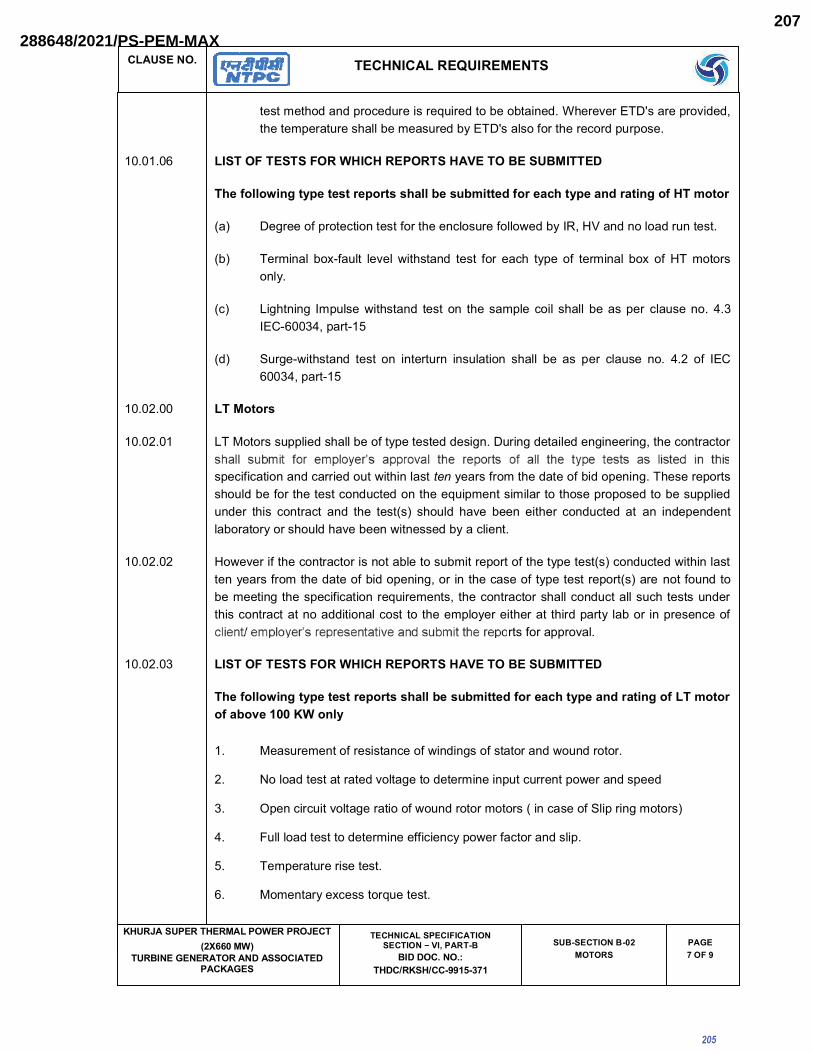
�������� ����������<�������
���������� ����������������� ���������
������������ ���������� ���������
������������>��� ����� ��� ?�@��� "�
����������� ���!���!��"##$%"'+$
��"�� ����"���� ��
����+ �>#
�������� ��������@��������������������������������� ���"����[����������"������� ��������������� �!!�����������������[�����!������ ����@����������
�������� �� �> � >������������ ��?� ������� ��
�|�\{{\�j��]��|]|_]^|�\^]__��{{�|_��~j]]|}�\^|�z�]��|��}^�]j��\�� ~\]\^
*�? �������������@������������� ����@!������!!_����������]��������!������������
*�? [������!� ��|���!�� !�"�!� _�� ������ ����� ��� ��@ � ����� �� �������!� ��� �� ][� ������!��
*@?� ��� ������ ����!���_�� ������ ������� � ������!��@�!� � �!!� ���������� @!��������<������|����<������|��
*�? ~����|_�� ������ ����� �� ���������� ����!����� � �!!� ��� ��� ���� @!����� ��� <��� �� ��������<������|��
�������� � �\]\^_
�������� �[����������!����� �!!��������������������������������������!����������������� ��@����@���
���@���@���������@����������_�� ���!����ten ����������� ���������������������[ ������������ �!��������� �������@���@������� ����������������!������ �������������������!���������� � ��� @����@�� ���� � �� ����*�?� � �!�� �"�� ����� ��� ��� @���@���� ��� ��� ������������!����������� �!�� �"�������_��������������@!�����
�������� ]_�"������� ��@����@�����������!�������������������� �����������*�?�@���@����_�� ���!������������������� ��������������������������� ��@���������������������*�?���� ���������������������� �����@���@�������������������� ��@����@���� �!!�@���@���!!���@ �������������� ���@����@���������������!�@��� �� � �����!������� ������� ����������!��������������@����
�����������"�!�
�������� �� �> � >������������ ��?� ������� ��
�|�\{{\�j��]��|]|_]^|�\^]__��{{�|_��~j]]|}�\^|�z�]��|��}^�]j��\�� ~\]\^\� ��\�|$�� ��\�{�
�� ����������������������@����_��������������������_��������
�� }�!�����������������"!�����������������������@��������_�������������
�� �����@��@����"!������������_�������������*����@������~!������������?�
<� �!!�!������������������������@���@���_�����@��������!���
�� [���������������������
�� �����������@���������������
205
288648/2021/PS-PEM-MAX207

�������� ����������<�������
���������� ����������������� ���������
������������ ���������� ���������
������������>��� ����� ��� ?�@��� "�
����������� ���!���!��"##$%"'+$
��"�� ����"���� ��
����� �>#
�� ]�� �"!����������
�� [�������"����������"������������
#� [������������!�"�!�������*~ �!!����!��������������@!������������������ �����@���?
��� [��������������������@��������
��� �"��������������
��� [������������������������!@�����������!��!������ �"�����!����������@!��������������~���<������������#|�
��������� \!!� �@@�����@�� ���� ������� ������ ��� ���� � �� ���@���@����� ���� ��!�"���� ���������� � �!!� ���@������������� ���������� ����� �!!������������������@!��������� ���������������@��
����<��� [ �� ����� ����� ������� �@�� ����"��� ��� ���� ����@��� � �!!� ��� �������� ��� �������@��� �����������������@�����}[������������������� ����_�!!���������� ������ � ��������@������
��� �������� �!!���� �� !�� ������� �������������� ����
����" �
���������> �����������>���?�� ��
�\]\^���j���
�j�j~�~ }j_]��z| �|]�||� z|�]^| \��\]]\~ ]|^~j��{ _]�} ��} �{��} �{�]|j�~~
��]\'�� �_�|^~�����z]�^|^�_�^�z]jz|�
\�"�������| �������� ��
\�"�������| ��������� ���
\�"��������| �����<��� ���
\�"���<����| ��������� �#�
\�"��������| ��������� �<#
\�"��������| ����#���� ���
\�"��#�����| ���������� ���
\�"��������|���������� �������� *�� ~���!�� @���@��!����!�?
206
288648/2021/PS-PEM-MAX208

�������� ����������<�������
���������� ����������������� ���������
������������ ���������� ���������
������������>��� ����� ��� ?�@��� "�
����������� ���!���!��"##$%"'+$
��"�� ����"���� ��
����# �>#
��][������� ��������@�����_�����!�����!��������� ���������!�������� �!!�������!����� ����������
���� �����!���� ���� ��������������
}�[�� �������� �����|� ���� ���� � ���|���� � ���� @!�����@��� ��� �[� ����� _�� � !���������!!���� �!!��������!!_��
�\]\^���j��� �{|�^��z|
������������� ����
\�"������������������������� ������
\�"��������� �#��
207
288648/2021/PS-PEM-MAX209

���������� ����������������� ���������
������������ ���������� �������������������� ���!���!��"##$%"'+$
����� ��
SUB–SECTION – B-3
� ����������
208
(AS PER APPLICABILITY OF SCOPE DEFINED IN SECTION IA & STANDARD ELECTRICAL SCOPE BETWEEN BHEL
AND VENDOR IN SECTION IB)
288648/2021/PS-PEM-MAX210

�������� ����������<�������
���������� ����������������� ���������
������������ ���������� ���������
������������>��� ����� ��� ?�@��� "�
����������� ���!���!��"##$%"'+$
��"�� ���"�"'
� ��������������$ �>�
$������ ����� ������
������� \!!� ����������� ���@���@������ ���� @���� �� ���@��@�� ��������� �� ������ � �!!� ��� � �� !����������������@!�������!!����!�@��!�����@��!������������������"�������������������������������� ��� @���� �� @��!�@�� ���_���� � ��� ���@���@����� ���� � ��� *�~� �� @����� ����������� ��@�?������������ �������� ��������� �!!����"��!��\!!�� ��@��!���� �!!�@�������� ������������������ ���!!_������������������@����
�~�����<�| � ��������!�����* ��"������?��!�@���@�@��!������_������"!����������
������@!������������
�~����#�� ��@��������@������������������@��!��
�~����#�� �_� @����� ��!"������� ����!� _������ ������ _����� ���� ������ ���
�����������@��!���
�~������� ��������!���������� ��� ����!�@���@�!�@��!���
�~���#��*�����|�? ����� !������ �!��� �!���� ����!����� ���� � ��� ��� @��!��� ���
_������"!����������������@!������������
�~������� ����@�����������!������!�@���@�!�@��!��������!����!��@�����
�~�����<�� ~��@���@������������������!�@���@�@��!���
�~�������� ��� ��������������@��!���
\~[�|� |��<� ~�������� ����� ��� �� ��� �������� �� ����� ���� � �� �������� ��
��@�����������!����@��
���|��<�*����|�?
[��������������"!"����������@�����������!�@���@�@��!���
���|��� [����� ���!�@���@� @��!��� ������ ����� @�������������|���[����������@ ���_�������@��!���*�������|�?�
������� ����������<�������
������� [ �� @��!��� � �!!� ��� ������!�� ��� !������ �� ��@���� ��� ��@���� ����@ ���� @������� ���� ������������������������!!�����_�� �@ ��@������!��������_�����
209
288648/2021/PS-PEM-MAX211

�������� ����������<�������
���������� ����������������� ���������
������������ ���������� ���������
������������>��� ����� ��� ?�@��� "�
����������� ���!���!��"##$%"'+$
��"�� ���"�"'
� ��������������� �>�
������� \!!�@��!�����@!����������@��!���� �!!�����!���������������!_������*��~?�����������������_�� �������!!���@ ���@�!���!�@���@�!������ ����!������������"�!����������������������������������������������@��������������@�������!��_ �������� ������@���@�����
������� \!��������@���@������������_���@��!���� �!!� �"�������!��������� �������� �������}�������������@����� �!!�������������
���<��� ����� ����!������ �!!����������!�� �����@��������@���@��� ��������������#�������������� ��� @��@���� @���@��� ������������ �� ���� ���� ��� ���� ����!����� � �!!� ��� ������!�� ���@�������� @���@��� ������������ �� ��� ������ ���� � ��� @��@���� @���@��� ������������ �������������
������� [ ��@��!��@����� �!!����!�������_�� ���!!�������_���� � ��@����_ ���"�����@������������ �!!���� ���@�� �� ����!��������� ������ � ��� ��\!!� � ��@��!����� ��� � �������!�� @�������������@��!����� �!!� �"��������@���������������������� ��� ����!�@��@!�����������~��������
������� ������!��@�����������@��!�������������� �!!����� �!��������_������������_����������!��@�����������@��!�������������� �!!��������!"�����������!�����!!_���
��!@�!����������!���������@��!��������������
~�^������[�����������
��������� ��<��������~�_����
\�"�����{��������� �������� �@���~�������_������������������~�_���
\�"�����{�����<���� ������� �@���~�������_�����������������~�_���
\�"��<��{��������� ��<����� �@���~�������_����������������~�_���
\�"�����{���������� ��<���� �@���~�������_������������������~�_���
\�"������ ��<����� �@���~�������_������<�����������~�_���
������� [ �� �!�������� ����� ��� ��������� � �!!� ��� �� ]<� ������ ��� ���� �~�� ����� _�� � ���������������"�������������<� ����� �����������������������[ ����^������!������������������ �!!����������������@�������"�������!"���^�������!�
������� [ ���������_����������_����� �� ������_����� � �!!� �����@�������������_���� �� ������_�������@������ � ����� �!!������@����"�����"��|���������������_������������_�����[ ���������� ����� �� @"������ �� ��������� � �!!� ��� #�$�� [ �� ��������� !��� �� ������ ������ �!!� ��� ��� !���� � ��� #�$� �� � ��� �� ������ _���� �� ������ _����� ��@� ��@ � ������ � �!!� ������!����������������������@������~�_�����������_����
������� ������� ��� �� �!!������������������~�������{��!�@�����@!��������������������������!!�� ��������������� �� ����������������� ��������� ��� ����� � ��� ����!!� � ��@��!���� �!!� �"�� � ���!!_������~�����������
*��? ���������������������#�*��������~�����������|��?�
*��? \@������������������������$�*����������|��<|�?�
210
288648/2021/PS-PEM-MAX212
�������� ����������<�������
���������� ����������������� ���������
������������ ���������� ���������
������������>��� ����� ��� ?�@��� "�
����������� ���!���!��"##$%"'+$
��"�� ���"�"'
� ��������������' �>�
*@�? ~�������������������� �!!������������ ������$�*�������\~[��|��<�?�
������� ����� �� � �� @��!��� � �!!� ��� �������������� @!������ �� ����!������ !!_����@!��� �@ ����� �!!�����������
��@���| ������!�@�����!!_����!��
��@�� | ����{��!�@�
��@�� | �������!!_�{��!��
<�@�� | �������!!_���!��������!�@�
���#��� ������@���������!�@���@������ ��@���� �!!�����!�@��
������� ����������� ��������@����������������@�������@��!���������� �~���!!_������������� �!!��!�������"�����"��������� ��� �
*��? ���!����^������"!�����������| [�����������
*��? �������~������"������������| [�����������
*@�? ~��������!�����������!���� ���� ��@��!����������������"����������������������������|[���������������������
[ �� ��������� � �!!� ��� ��������"��� �������@�� ��� !���� ���� �������� � �!!� ��� !����!�� ��������!��!�� ������@��!�����������@������ �!!�������������������� ��� �
������� \!!�@��!���� �!!������� ���������������@����������������������������|����������������|��
������� \!!_��!���!����@������ ��"���!!������������� ��@��!���� �!!����`¡|��������������"���� ����@!�����"�!������� ����@ ��@�!������� �����
������� ����!��������������� ��@��!���� �!!��������@@�����������!������� �������!_� !�����@����������@@�����!��
���<��� ���!�����!�@����{���^���
���<���� ���!���� �!!������^������������ ���!!_����@������������
*�?� ������@���������� �����������
*�?� [ ��"!������������� ��@��!�����������������������@��������� �!!����!�����������$��������������!!�!�����������@��������� �!!����!����������$���� ��������"!����
*@?� ~ ���@��@����_�� ������@�����!���
[ ��� _�!!� ������� �� � �� ������� ������ �� �� ����� ����@���� @��@����� @��!�� � �!�� �����^�����_�� ������� ��!��������������� ������������������@���!!�����������@��!��� �!!� ��� @����!�� �� _�� ��������� � �� ������� ���!�� @������� !�"�!� ��� ���!� ������������������������@!���"������!�����@���������
211
288648/2021/PS-PEM-MAX213

�������� ����������<�������
���������� ����������������� ���������
������������ ���������� ���������
������������>��� ����� ��� ?�@��� "�
����������� ���!���!��"##$%"'+$
��"�� ���"�"'
� ��������������` �>�
���<���� ����������@���
��������� ��@���� ��� "������ @�������� �� �����!!������ ��@!������ � �� �!!_���� � �!!� ���@���������_ �!����!�@������ ��@��!����^���
�? �����������������������������������@��!���!����������
�? ����������@��!��
@?� ������������������������������������!��������"��������������@��!���
���<���� ���!�� !���� �� � �!!� ��� @��������� ��� ��@ � �� _��� � ��� ������ �� � ��� � � @��!�� ������ �����"�����
���<��<� \!!����!���� �!!�����������������
���<���� \!!��[��_���@��!�������^�������� ��������������� �!!��������������!�����������^�� � �!!��� ������� �����������������������{�����<���������]_�"������@��!����^�������������������� ����������!�����{���������!������[��_���@��!��������@@�����!��
���<��� ~����@��!����^��� ���������� ������������������!�@�����{�������������� ���� ��� � ��������� �������������������!�@�������!!�� ��������������� �!�������"�����_�� ������@��!�����^���
'������ ��� ��� �����>�� ���
�������� ��������������_������!��
*�? �������������������_���@��!���� �!!� �"��@���@�����!��������@���@�������������!������ ���� �����|� ��� ��� *��� ���!�@��!�?�� ��������� ���� ����|� ��� ���@�����������~���#���*����|�?�
*�? �����������������_���@��!���� �!!� �"���!��������@���@��*@���@��������������^��� ��"�� ��� �����?�� ���� ����!������ ���� ������ � ��� ��� *��� ���!�@��!�?������������������|� ��� ���@�����������~����<�*����|�?�
*@? �������������[���!����@��!���� �!!� �"���������@����*@!�����?@���@��������!�����_�� � ���� ���������� �!�������@� @������ ������ �� �� �!���� ����!����������*���?�������!�����_�� ���������#��������@��������@���@���������������������������� ������� � ��� @��@����� �����|� ��� ��� _�� � ���� ���������� �!�������@�@���������!��@���������@��������|� ��� ��� �_�� � ���� ������������!� ���������������!�������������� ��"��������!�������@�@������@�����������~�##���
`������ ���������
*�? ���!��� � �!!� ��� ����!���� ��� ��� ��������!�� _���� �� ����!� ������ �� ��"������@�����@����� [ �� �����@�� �� � �� ����� ���� � �� ����� ���� @��!�� !����� � �!!� ���@"����� _�� � _����� ���� @"���� �� � � �� ����� �� � �� @��!��� � �!!� ��� �����!�����!��� _�� � ���� � ������!�� ����� ������� @���� ��@����� ��� ���� ���!�� �� ��� ���!�������� �������� �� _����� ������� �������������� ������� ���� ���@����� ���������"���"�� ����|�������� ���������� � �!!� ��� ���!���� �� � �� ������� ������ ������������ �!!�@��!��_�� ��~����<���
212
288648/2021/PS-PEM-MAX214

�������� ����������<�������
���������� ����������������� ���������
������������ ���������� ���������
������������>��� ����� ��� ?�@��� "�
����������� ���!���!��"##$%"'+$
��"�� ���"�"'
� ��������������% �>�
*�?@����@�� �������� ����� ������� ���� ������ ��^�� ���� !���� � �� @��!�� ���� ���� �����_��� ������@�!!������� ���������� ��������\�����@������������������������� �!!��������@ ����� � �� !�������������� ��@��!���\�����_�����������!���@@���������_������� �!!����������������������� �����!� ����@������ � ������@���� ���_ �@ ����� �!������!!���
*@�? [ ���������������� !���� ����[��_��� @��!��_�� ����������� �!����@��� `�|�$����������@��������� ��������������@����@�������� ���� ����� �!!�������������������@��!���_ �������!�@�����!���� ���@��!����������{���@!�������������������� ����!�� @��� @��!�� ��@!������ ���� ����� ��^��� ���� ���� ������ ��� ��!��@���@��!��{�����!��@�����������
%������ �
��� \!!� ����������� �� ��� ����!���� � �!!� ��� �� ����� ������� �������� � ������� �����!���
��������������!���������� ������@���@���������@����������_�� ���!������������������� ������� �� ���� �������� [ ���� ������� � �!�� ��� ��� � �� ����� @���@���� �� � ������������ ����!��� �� � ��� ������� �� ��� ����!���� ������ � ��� @����@�� ���� � ������*�?� � �!�� �"������� ��� ��� @���@���� ��� ��� ������������ !�������� �� � �!�� �"�������_��������������@!�����
��� ]_�"��� ��� � ��@����@�����������!����������� ��������� ������� ����*�?��@���@����_�� ���!������������������� ��������������������������� ��@���������������������*�?����� ��� ����� �� ��� �������� � �� ���@���@����� �������������� � �� @����@��� � �!!�@���@���!!���@ �������������� ���@����@���������������!�@������ ��_�������� ������� ����������!��������������@����@!������_�����������������"�������������� ����������������"�!�
��� \!!��@@�����@��������������������������� �����@���@�����������!�"��������������� �!!����@������������� ���������� ����� �!!������������������@!��������� ���������������@��
<�� [ �� ����� ����� ��������@������"��� �����������@���� �!!���� ������������������@����� ����������� ����@��� �� }[������� ����������� � ���� _�!!� ��� ������ ��� ��� � ��
� �!!���� �� !�� ������� �������������� ����
������� ��| |_]_
������� [ ������������� ���!!_���������������� �!!����������������������^����@ ����[�����������[������_���@��!����~�^��� �!!������@��������� �����!����������������!���������������
��\� ��|]|_] �|~�^�_>\^�\�}�z]\^
�� ��������@������
�� [����!������ �� @��@�!�� ��|@���@������
@���@�����!�����������
�� ������������� ��@��@�!�����|@���@�����!�
213
288648/2021/PS-PEM-MAX215

�������� ����������<�������
���������� ����������������� ���������
������������ ���������� ���������
������������>��� ����� ��� ?�@��� "�
����������� ���!���!��"##$%"'+$
��"�� ���"�"'
� ��������������� �>�
>\^�^~\�^�j^|_!>\^~|}�j^|_<� ������������������������
�� [����!��[���
�� �!�����������
�� [��������� �������_������!�
�� ������������� �� �!�������� _����� �� ������
_������!��
#� ��������@������
��*�? ������� �̂�@�@���������� ���~������_�����_������!�
��*�? ������������^��@�@����� ���~������_������_������!�
��� \� ��������� ���~������_�����_������!�
>\^�?�!����j�_�{�]j\���?��|�]���� [�������� �@�����
��� [����!��������� �{��!������������ �����������������������������
�<� \�������������"��
��� ��������������� ����������!���������� ��� ��!�
��� ]���������������� ����������!���������� ��� ��!�
��� ]����� @������ ����������!���������� ��� ��!�
��� ~ ������������
�#� [ ����!������!�������� ����������!���������� ��� ��!�
��� ]���������� �����������!������!�
��� �������������������� �����������!������!�
��� ����������������� ��������� ��� ��!�
��� ~���������������� �������� ��� ��!�
�<� \@��������������������� �������� ��� ��!�
>\^z\~�{|]|}z��{|_
��� ����!�������������@�������
*�!�����������"������� �?
��� ]�� �"!���������
��� !������!�������������������|��������|��*�������|�?
����@���"�� !���� �� ������@ �@���� ������� ���� \@@�����@�� ������ � �!!� ��� �� ���� ¢��!����\������@��{������@�������!�����[��_���@��!�����@!����
214
288648/2021/PS-PEM-MAX216

���������� ����������������� ���������
������������ ���������� �������������������� ���!���!��"##$%"'+$
����� ��
SUB–SECTION – B-4
� ��� ��������
215
(AS PER APPLICABILITY OF SCOPE DEFINED IN SECTION IA & STANDARD ELECTRICAL SCOPE BETWEEN BHEL
AND VENDOR IN SECTION IB)
288648/2021/PS-PEM-MAX217

�������� ����������<�������
���������� ����������������� ���������
������������ ���������� ���������
������������>��� ����� ��� ?�@��� "�
����������� ���!���!��"##$%"'+$
��"�� ���"�"`
� ��� ������������$ �>�
$������ ����� ������
������� \!!� ����������� ���@���@����������@���������@��@�� ��������� �� ������ � �!!� ��� � �� !����������������@!�������!!����!�@��!�����@��!������������������"�����������������������������������@������@��!�@�����_����� ������@���@���������� ���*�~���@������������������@�?���������� �� ������� � �� ������ � �!!� ���"��!�� \!!� � �� @��!��� � �!!� @����� �� � ������������������ ���!!_������������������@����
�~�����<�| � ��������!�����* ��"������?��!�@���@�@��!������_������"!����������������@!������������
�~����#�� ��@��������@������������������@��!��
�~����#�� �_�@�������!"�����������!�_������������_�����������������������������@��!���
�~������� ��������!���������� ��� ����!�@���@�!�@��!���
�~������� ����@�����������!������!�@���@�!�@��!��������!����!��@����
�~�����<�� ~��@���@������������������!�@���@�@��!���
�~�������� ��� ��������������@��!���
\~[�|� ��<� ~���������������� ������������������������� ��������������@�����������!����@��
���|��<�*����|�? [��������������"!"����������@�����������!�@���@�@��!���
���|��� [��������!�@���@�@��!��������������@�������������|���[����������@ ���_�������@��!���*�������|�?�
������� ����������<�������
������� [ ��@��!���� �!!� ���������!�� ��� !����������@���� �����@���� ����@ ����@�����������������������������������!!�����_�� �@ ��@������!��������_�����
������� \!!� @��!��� ��@!������ ���� @��!��� � �!!� ��� �!���� ����������� !_� ����� *��~?� �������������� �� _�� ������ �!!� ��@ ���@�!�� �!�@���@�!� ���� � ����!� ��������� ��"�!�� ������������� ������ ���� ���������� ��������� @�������� ��� ���@������ �!��_ ���� ��� � ������@���@�����
������� ����@�����@���!�@��!���� �!!����������������������!���������!���@�����
���<��� ��������!������ �!!����������!�� ���@��������@���@��� ���������������������������� ���@��@����@���@����������������������������
������� [ �� @��!�� @���� � �!!� ��� !���� ��� _�� � ��!!���� ���_���� � �� @���� _ ���"��� ��@�������� ���� �!!� ��� ���@�� �� ����!����� ���� ������ � ��� �� \!!� � �� @��!���� � ��� � ��� ����!�� @�������������@��!����� �!!� �"��������@���������������������� ��� ����!�@��@!�����������~�������
216
288648/2021/PS-PEM-MAX218

�������� ����������<�������
���������� ����������������� ���������
������������ ���������� ���������
������������>��� ����� ��� ?�@��� "�
����������� ���!���!��"##$%"'+$
��"�� ���"�"`
� ��� ������������� �>�
������� ����!��@�����������@��!����� ������������ �!!��������!"�����������!�����!!_���
��!@�!����������!������@��!�������������
~�^�������[�����������
��������� ��<��������~�_����
\�"�������������� �������� �@���~�������_�������������������~�_���
\�"���������<���� ������� �@���~�������_�����������������~�_���
\�"��<���������� ��<����� �@���~�������_���������������~�_���
\�"�������������� ��<���� �@���~�������_������������������~�_���
\�"������ ��<����� �@���~�������_������<�����������~�_���
[ ���������_����������_�������������_������ �!!������@�������������_������������_�������@������ � ����� �!!� �����@����"��� �� "��|���������������_���� �� ������_�����[ �����������������@"������������������ �!!����#�$��[ �����������!����������������� �!!�������!����� ���#�$���� �����������_������������_����� ��@���@ �������� �!!��� ���!����������������������@��
������� ������� ��� �� �!!������������������~�������������������@!��������������������������!!�� ������������������������~��������������������������� ��� ����!!�� ��@��!���� �!!� �"��� ���!!_������~�����������
*��? ���������������������#��*\�������~�����������|��?
*��? \@������������������������$��*\���������|��<|�?
*@�? ~�������������������� �!!������������ �����$��������~������������[�����������\~[��|��<��
������� �������� ��@��!�����������@����� �!!������������������@!������������!������!!_����@!����@ ����� �!!�����������
��@��� | ������!�@�����!!_����!��
��@�� | ����{��!�@�
��@�� | �������!!_�{��!��
<�@�� | �������!!_���!��������!�@�
��@�� | �������!!_���!�����!�@����������
���#��� ��@��!��� �"��������� �����@�����@�����������@������ �!!���������������������� ������!�������@�������������!!��� ��������������������� ��� � �� ������ !����� *��������� ������@���@��!���@�������������� �!!��������������?��[ ���������� �!!��� �����������]����|\����@�������!����� ������������@������ ��@�����\!!�� ����������� �!!������� �������@!����_ �@ �� �!!�@�������_�� �� ��@!���������!������[ ��@!���������!���������!!�� ��@����� �!!����������!���[ ��������!��� �!!����!����!����������!��!���[ ����������� �!!����������������������!��� �����"�!���!���� ��@����@���@���"������������������"�����������!���������@ �� ����� ���� ������������������!��������!������� �� �!!�����!�@��
217
288648/2021/PS-PEM-MAX219
�������� ����������<�������
���������� ����������������� ���������
������������ ���������� ���������
������������>��� ����� ��� ?�@��� "�
����������� ���!���!��"##$%"'+$
��"�� ���"�"`
� ��� ������������' �>�
��������� ��������� ���������@����������_�������!���� ����� �!!�����������������!_�� ��� ������������ ��!�@�����!_�� ��!_���������!��[ �����@�������_����@���@���"����������� �!!������@����������
������� ����������� �� ������@�������� ��������@����� ��@��!��� ��� ���� �~�� �!!_���� �������� � �!!��!�������"�����"��������� ��� �
*��? ���!����^������"!������������| [�����������
*��? �������~������"������������| [�����������
*@�? ~��������!����������� !���� ��� � ��@��!�� ��������������"������������� | [����������������������
[ ����������������������� �!!������������"����������@�����!����������������� �!!����!����!����������!��!�� ������@��!�����������@������ �!!�������������������� ��� �
������� \!!�@��!���� �!!������� ���������������@����������������������������|�������|��������|��
������� \!!_��!�� �!����@����� � ��"���!!� ����������� � �� @��!���� �!!� ��� `¡|�������������"���� ����@!�����"�!������� ����@ ��@�!������� �����
������� ����!��������������� ��@��!���� �!!��������@@�����������!������� �������!_� !�����@����������@@�����!��
���<��� ���!�����!�@����{���^���
����!�@��!���� �!!������^������������ ���!!_����@������������*�?� [ ����������@���@���@���|��@����� �!!��������������
*�?� [ �������������������������@�������@���!�@��!���� �!!��������!!_��
}����@�������@��!� �����}����������@���
������ }��
�� �
��|��� �
�<��{���"� �
���<���� ���!�� !���� �� � �!!� ��� @��������� ��� ��@ � �� _��� � ��� ������ �� � ��� � � @��!�� ������ �����"�����
���<���� \!!����!���� �!!�����������������
'������ ��� ��� �����>�� ���
������� ���� ��� ������ ����!� ���!��� � �!!� �"�� ��������� @����� @���@��� ���� � �!!� �����!��@�����������!����������������� ��� ���������������������������~����������� ��� ���@�����������~�����<��*����|�?�
������� �������������[���!����@��!���� �!!� �"���������@����*@!�����?@���@��������!�����_�� � �������������� �!�������@� @������ ������ �� �� �!���� ����!���� ������*���?� ������!�� ���_�� ���������#��������@��������@���@������������������������������������ ���@��@����������|� ��� ��� _�� � ���� ���������� �!�������@� @������� ��!�� @��� ������@���� ����|
218
288648/2021/PS-PEM-MAX220

�������� ����������<�������
���������� ����������������� ���������
������������ ���������� ���������
������������>��� ����� ��� ?�@��� "�
����������� ���!���!��"##$%"'+$
��"�� ���"�"`
� ��� ������������` �>�
� ��� ��� � _�� � ���� ����������� �!� ���������� ���� �!���� ���������� ��"�� ����� �!�������@�@������@�����������~�##������������@���@�����^��� �!!�������������
`������ ���������
*��? ���!��� � �!!� ��� ����!���� ��� ��� ��������!�� _���� �� ����!� ������ �� ��"��@�����@����� [ �� �����@�� �� � �� ����� ���� � �� ����� ���� @��!�� !����� � �!!� ���@"����� _�� � _����� ���� @"���� �� � � �� ����� �� � �� @��!��� � �!!� ��� �����!�����!��� _�� � ���� � ������!�� ����� ������� @���� ��@����� ��� ���� ���!�� �� ��� ���!�������� �������� �� _����� ������� �������������� ������� ���� ���@����� ���������"���"�� ����|�������� ���������� � �!!� ��� ���!���� �� � �� ������� ������ ������������ �!!�@��!��_�� ��~����<���
*��?@����@�� �������� ����� ������� ���� ������ ��^�� ���� !���� � �� @��!�� ���� ���� �����_��� ������@�!������� �� ����������� ��������\�����@������������������������� �!!� ��� ����@ ��� �� � �� !������� ���� �� � �� @��!��� \�� ���_� ���� ������!���@@��������� _������ � �!!� ��� ������� �� ��� ���� �� � �� ���!� ����@������ � ������@�������_ �@ ����� �!������!!���
*@�? [ ���������������� !���� � ���@���!� @��!���_�� ����������� �!����@����`�| �$���������@��������� ��������������@����@�������� ���� ����� �!!�������������������@��!���_ �������!�@�����!���� ���@��!����������{���@!�����������������
%������ �
\!!���������������������!����� �!!���������������������������������������!����������������
��� � ��� ���@���@����� ���� @������� ��� _�� ��� !���� ���� ������ ���� � �� ����� �� ���� ��������[ ���� ������� � �!�� ��� ��� � �� ����� @���@���� �� � �� ���������� ����!��� �� � ���������� �� ��� ����!���� ������ � ��� @����@�� ���� � �� ����*�?� � �!�� �"�� ����� ��� ���@���@����������������������!����������� �!�� �"�������_��������������@!�����
]_�"������� ��@����@�����������!�������������������� �����������*�?��@���@����_�� ���!���� ���������� ����� ����������������������� ��� � ��@������ ����� ����� �����*�?��������������������������� �����@���@�������������������� ��@����@���� �!!�@���@���!!���@ �������������� ���@����@���������������!�@�� ��� ��_�������� ������� ���������� !����� ���������@����@!������_�����������������"�������������� ����������������"�!�
\!!��@@�����@��������������������������� �����@���@�����������!�"��������������� �!!����@������������� ���������� ����� �!!������������������@!��������� ���������������@�
[ �� ����� ����� ��������@������"��� �����������@��� � �!!���� ������������������@���������������� ����@��� �� }[���� ��� ����������� � ���� _�!!� ��� ������ ��� ��� � ��
�� !�� ������� �������������� ����
������� [�� �
������� [ ������������� ���!!_���������������� �!!����������������������^����@���!�@��!�����~�^��� �!!������@��������� �����!����������������!��������������
219
288648/2021/PS-PEM-MAX221

�������� ����������<�������
���������� ����������������� ���������
������������ ���������� ���������
������������>��� ����� ��� ?�@��� "�
����������� ���!���!��"##$%"'+$
��"�� ���"�"`
� ��� ������������% �>�
��\� ��| |_] �|~�^�_
>\^�\�}�z]\^
�� ��������@������
>\^�^~\�^�j^|_!>\^~|}�j^|_������{jz��{|�
�� �����������������������
�� [����!��[���
<� �!�����������
�� [���������� �������_�����!�
�� �������������������������������������� ���!��������_�������������_������!��
�� ��������@������
�*�?� ������� �̂�@������������������������������� ���~�_�����������_������!�
�*�?� ������������^��@�@����� ���~�_�����������_������!�
#� \� ��������� ���~ _�����������_������!��
>\^ �?� j�_�{�]j\� � �?��|�]�
��� [�������� �@�����
��� [����!�� ������� � ������!������������
�����������������������������
��� \�������������"��
��� ������������������������������������������������ �� ���� ����!����� ���� � ��� ��!�
�<� ]����������������� �� ���� ����!����� ���� � ��� ��!�
��� ]����� @������� �� ���� ����!����� ���� � ��� ��!�
��� ~ ������������
��� [ ����!������!���������� �� ���� ����!����� ���� � ��� ��!�
��� ����������������� ��������� ��� ��!�
220
288648/2021/PS-PEM-MAX222

�������� ����������<�������
���������� ����������������� ���������
������������ ���������� ���������
������������>��� ����� ��� ?�@��� "�
����������� ���!���!��"##$%"'+$
��"�� ���"�"`
� ��� ������������� �>�
��\� ��| |_] �|~�^�_
�#� ~���������������� �������� ��� ��!�
��� \@��������������������� �������� ��� ��!�
>\^z\~�{|]|}z��{|_
��� ����!�������������@������*�!�����������"������� �?
��� ]�� �"!����������
��� !������!�������������������|��������|��*�������|�?
������� ����@���"�� !���� �� ������@ �@���� ������� ���� \@@�����@�� ������ � �!!� ��� ��� ���� ¢��!����\������@��{������@�������!��������!����!�����@!����
221
288648/2021/PS-PEM-MAX223
���������� ����������������� ���������
������������ ���������� �������������������� ���!���!��"##$%"'+$
����� ��
SUB–SECTION – B-5
���������� �������� ���������� �� ���
222
(AS PER APPLICABILITY OF SCOPE DEFINED IN SECTION IA & STANDARD ELECTRICAL SCOPE BETWEEN BHEL
AND VENDOR IN SECTION IB)
288648/2021/PS-PEM-MAX224

CLAUSE NO. ����������<�������
���������� ������ ����������� ���������
������������ ���������� ���������
������������>��� ����� ��� ?�@��� "�
����������� ���!���!��"##$%"'+$
��"�� ���"�"�%�������@��� �����
���� ������� �� ���
����$ �>�'
$������ ������� ������
�������� \!!� ����������� ���@���@������ ���� @���� �� ���@��@�� ��������� �� ������ � �!!� ��� � �� !����������������@!�������!!����!�@��!�����@��!������������������"�������������������������������� ��� @���� �� @��!�@�� ���_���� � ��� ���@���@����� ���� � ��� *�~� @����� ����������� ��@�?������������ �������� ��������� �!!����"��!��\!!�_���� �!!����@������������������ ���!!_���������������@����������!�@��!���
�~���� �!���!!���!_�@���������!�� ����������������
�~���� ���� � �� ���@��@�� ��� � �� ���� �� ~���@����!� ~���!� ��� �"�� ����[����������������[_����
�~����# ]���!!���@���������!�� ����{�������
�~����# ��!������!������������!��������� ���_��� ������!���������
�~����� ���� �� ���@��@�� ��� �����!!����� ���� ���������@�� �� �_���@��!�������������@!������������������
�~����������|�� [�@ ��@�!� ����!�� @�������� ��� � ������� ~���!� ����������� *]��������!"���^���@���������� ����������������?�
�~���<� ������� �� ����@���� ��"����� ��� ��@!������ ��� !_� "!������_��@ ���������@���!�����
��������� ���� �� ���@��@�� ��� � �� ����@���� �� ���!����� ���� �!!��������@��������������!�� ������
�~����# ���� �� ���@��@�� ��� � �� ����@���� �� ���!����� ���� �!!��������@��������������!�� ������
�~����# ��@�����������@��@����� ��������!"��������������{�����!
�~����� ��� �������������������������@��������^��@�@���������@!���
�~���<� ���������@��@��������� ���
�~����� �������������!��@�!���@�����!�����@�����������_�� ����
�~���<� ��� ����������������������������^��@�@��������^��@�@���������{�����!�����@!���
�~����� ���������� ����� ����!��� ��| !���� @���@���� ��� �!��������@���@����������!�����@��!��
�~����# ���������� ����� ����!��� �������!� ����� ��� �!��������@���@����������!�����@��!���
�~�#��� ������������!�@���@�!������!!�����
�~�#�#� ����!� | ��@� _�!����� �� @����� ���� @����� ���������� ����!� |��@�����������
�~������ ��������������������������!�����@�@��!���
�~�<�� ���������������!������������!����������@�����
223
288648/2021/PS-PEM-MAX225

CLAUSE NO. ����������<�������
���������� ������ ����������� ���������
������������ ���������� ���������
������������>��� ����� ��� ?�@��� "�
����������� ���!���!��"##$%"'+$
��"�� ���"�"�%�������@��� �����
���� ������� �� ���
����� �>�'
������� ������������������������\��������������������
������<� ��������������������!�{�@����@��!��_����������
��}��<�����*����|��? }�������������@�������������������\!��������@���@����
��}�<���# ���!�� !���� ��� @��������� @���@������ ����� � ����� ����\!��������@���@���
�~����� ~��@���@����� ��� ��@ ���@�!� ���!�� �!����� ��� �!�������� �����!����@�����!�����@��!���
��������!�@���@����\@��
��������!�@���@������!���
�������� ����������@��!�����_�� �� ��� �����������!!���@@������������������@ ����������~����}���~\�� ����� }��\ ��@�� _�!!� �!�� ��� @��������� ��� � ��� ������� ��������@�� ����@�����@����!��������������"�!��������������������������!��������"��������@ ���@������ ���������� �!!�@!���!������@����� ����������*�?��������������� ���@���������!�� ���� ��!��������"�������� �������������!��_�� �@��������!!����@��!������������������"�����������@�������������������������������� �!!�@!���!������������ ����!�����������������@��������
������� ����������� ��� �����>�� ���
�������� ��]|^�{��]���{j��
�������� ������!����@��!���� �������� ������� �!!���� !�����!���"�� ���� �����!�����@������������!�������������!�������_��@ �����@���!����� �!!����!�������"�� ���������!�������@������� ���@������ ��@�� ���������!!|����� � �!!� ��� ��!!��� _�� � ��������� ��"����� _�� ��� ����@"����������@�!�������� @��!���������������!��� �!! ��� �"��@�@���������������� ���<�@��!�������������� \!!�][���[���������!�@��!���� �!!�����������
�������� ^��_�\^~|^��^}
�������������������@��!���� �!!���� !�������"�� ���������!���[ �������@��!��������@�������� ���� ����� �!���� ���!���������@������� � �� [���������� ������ �!!� ��� !���� ���"�� ���������!���� �� ����������� ������ �����!�� ��� �� ��� ���!����� @������� � �!!� ��� ������!�� ����"�����������������[����������_�� ���� ����
������� ^|�z�|_
�����!����������!����� ����@ ���� �!!�����!�����������@��"�����������_�� ��������������������������
������<��� }�����^��� !�"�!�@��!��"��!������@ ���� �!!���� ��"�������!_�@���! ���!������_��@ �����������������!����
������� ���{|?��{]
[ ��@��!��"��!�����@��!�����������������@����!_�� ��][����[��_��@ �������������!�����������@���!�������������������������������~��� ������{���������������!����������� �!!� �"� ���~~�j}| ���������� �� ��"���������������!!�������� ��@��!������������ ��@��!��"��!���@��!����������������������!���������������@����@��!��
���!��"��!���� �!!������"�����_�� ���������������������@�!�������������������������_�����
224
288648/2021/PS-PEM-MAX226

CLAUSE NO. ����������<�������
���������� ������ ����������� ���������
������������ ���������� ���������
������������>��� ����� ��� ?�@��� "�
����������� ���!���!��"##$%"'+$
��"�� ���"�"�%�������@��� �����
���� ������� �� ���
����' �>�'
��@ �@��!��"��!��� �!�� �"�����!������_�����
������������ �!!������"������������������������!���@�������@�������������@�
���������� �\j{|^�^|�
[_����������@��!���������������@ ������� �!!������"����������@ ���!�������������!������������������!���������@ ������������\�����{� �!����� ��@�!���!!��� �!!���������������������{����� �������������!�������� ��� �� ��������
���!�� ������ �����!��� {� �~�� ����� � �!!� ������������ ���� � ����!��� ���� �~�� ����@��������[ �������� �!!����@���������_�� �~���~��@����@���
���!�� ������ ��� � ���� ������ � �!!� ��� ��� "����@�!� �������� �� �"��� ����� �@@���!������ }�@��!������@ ���� �!!������"����������!����~�������
������� �^�j�|��{{�^|��?[_� ��������� @��!�� ������ � �!!� ��� ��"����� ��� @��!�� ������� �� _������ ���� �����������"������������������������*������$�@���@���?�������!�������
������� ���j]|�^|�
�������������� ������"�� ����@��!������ ������������� �!!��� �!!_����]_�"���@��!������@ ����������@�����������!_��_��@ ������@@�[����!��������!��!������ �����"�� ����@��!���������������������� �!!������"��������������@ ��� ��"����� ��� ���� ��� � �!!� ��� ���������� ���� ���!� �!� ����� �� �"��� �!��@@���!�����
������# [ ��@��!���!�������������� �� ���������������_���@���!�����!��� �!!��������� ��!!���{�@"�����_�� �����������@��!����
������� ~�^���� @��������� ��������� ��@���� ��� � �� @��!��� � �!!� ��� ���� ��� ���� �����@��"�� @ ��������]_�"������� ���_���@��!����� ����������@���@�����^��� �!!�����������������!��������@���@���������������������@�����@���@���@��!��
������� ���@������@���������� ����"�������!����������������@@���������������@��!�@������������������!������������ �!����������������@ �!@�������
������!!��������������������~���������������������� �^��������@ ���@�!����������!�������_�������!��@@���!�������!�@���@�!����!�������������@������@
'������ �<������ ������ ���
�������� ���{|]^��_@>j]]j��_��zz|__\^j|_
�������� ���!��������� �!!����!���������������������������@������@��!����_�� ����@ �������������*!�������@�������!�_��������������@�����������@���������@�?��@@��������*!���������@��!����!��������@������ � ���_����*!�����!����������_�� ����������������� ����@�?�����������������!�������� �!!����!���������������_���{�@���!�@��!�����������������������������������@��!���
�������� ���!�����������������������@@��������� �!!���������@�����������!!�����!������!�� ���������������!�_����@ ����!������������!!���������������������@��[ ����*��@!������ ���_���?�� �!!���� ��������!"���^�����������!�����}������������� ���@ ������
225
288648/2021/PS-PEM-MAX227

CLAUSE NO. ����������<�������
���������� ������ ����������� ���������
������������ ���������� ���������
������������>��� ����� ��� ?�@��� "�
����������� ���!���!��"##$%"'+$
��"�� ���"�"�%�������@��� �����
���� ������� �� ���
����` �>�'
�������� ���!��������� �!!� �"�����������_��� ������������������{���������������������!���� ���������������[ �@����������!������!�� ������������� �����@���� ��@��!���������������������� �!!����������[ ��� �@�������������@��!����!������ �!!���������
������< ���!������ ��� �!!��������������������@ ���������_�@��!������������@��!��������[ ����� �!!�����|� ������ �����@���������!������!�� ������� � �@���������������� �!!� ��� ��������!"���������������!�����}������������� ���@ ������ [��� ��� �!!�������������_��� ���������{�������_�� ����� ���������
������� [ ���!����@�����@��!������������@@��������� �!!������������~������*����|�?�[!����@���!�����| �����
�������� ���\^]�_]|~�\^���{| ^��_
�������� ���!���������������������� �!!�������|�����@��������������!��� �������������@!��������������_�����
�������� ~����������������@��!�� ������� �!!���������!!��@��������� � �� �_�@������� �����������������@ ����!�����@����!�"���������[ ��������������@ ����!�� �!!������ �_� ������ �� *�?����| �"������"������������������@��!����������������������*��?����| �"������"������������������ @��!�� ������ �� �� � ������� [ �� ������� ������� � �!!� ��� � �� ����� ���@������ ��������
�� ���!�� ���������� ����!� _��� ��� @��!�� ��@���@��!��� � �!!� @������� �� "������@ ����!� ��@������ @����!�"��� ������ "������ ���@������ @!������ �!�� �!������ �!!� ���_�������@ ����!@��_�� ����� ������������ ������ �����!���������� ��������������� ������ �����@��_��@ ����!������@ ����!�����_�� ��������������������������@��
�� [ ��������� � �!!� ������������ ��@ � � ��� ��� �!!_�� ����� ������!�� ��� ����� ��� �������!������\!!�@��!����������������!�_���� ���_������������������@@��������� �!!������������@�������@������!"������������������
@� [ �� ����� ������� ���� @����!�"��� ����� � �!!� ��� ������ ��� ����� ������ ��@����������@������ @!������ ���������� �!���� ����� ���� � ��� ���_���� ��@�� �� ���� "�������������������������������������� ��@��!�����������!�������� ��@��������� �!!��������!!_����]_�"����_�!�������� �����@����*��_ �@ �� ��������������@ ����!���� �!���?� �� � �� "�� ���� ������� ����@����!� ����!�� ������� �!����� �� ������@����������� _�!!� ��� ����������� \��� @������� �� _�!����� �� � �� ��!"������� �����@�� � �!!� ������� �����������!�������������!��������{��!��������������� �!!�������!���
�� \!!�����!�@����������@@�������� ������������� ���_����� �!!���� ��������!"�������������@��!������_�!������@�����������!!��� ����� �����@ ��������������
�� [ �� ����@�!� ������������ �� �!����!�� ������� ������� ��� � _�� ��� � �� ��@!�������_������������@�����������!����!_�
[ ��������������@ ����!�����@����!�"��������� �!!� ��� �����@�������������� � �@���!!�������!�� ����@�����������~ ���#�
�� �����!�"��������������� ��������� ��������������!���� �������������������� �!!���� ��� � _�� ��� � �� ��@!���� ���_����� [ �� ���� ������ � �!!� ��� ������!�� ���������!���� � ��@��!��������������!���� �� @������� @�����@������ ���������@ ����!���@�����[ ����@���!����� �!!��!!_������@�����@!�����@�������������!���������� ������_�� ����������������
�� ~�������������� �!!������!����_�� �����
226
288648/2021/PS-PEM-MAX228

CLAUSE NO. ����������<�������
���������� ������ ����������� ���������
������������ ���������� ���������
������������>��� ����� ��� ?�@��� "�
����������� ���!���!��"##$%"'+$
��"�� ���"�"�%�������@��� �����
���� ������� �� ���
����% �>�'
_��� ����� ��@��!�������_��� ����� ��@��!���*��������������������@ �@��!������?��@���������!��������������_�����"�����������������@��������������������������� �!!����@���������
�������� [ ����^���� ����@����!� ����!����������� � �@�������� � ���� ����!� �� ����� ������� @ ����!�����@����!�"������������� ����@@���������������@�������"�������� ����@!�������_�������������@���"���!���}�"��� �!������ ����������������� �!!����������������� �������������!!������� � ����������������������������������@������� ���@���� � ������������!�� ���� �� ������� � ��@��������������������@������ �!!������������ ���������_�� ���������������!�@������ �����!�����[ ���������� �!!�������� � �������!������_������� � ������������������� ����!��_�� �� ������
������< ���!����������@������ �!!������"�����_ ���"���� �������@ ���������!�"���� ����@ ������������@���
������< ��� ��\��� ����~[�}�� \}�� ���~�� ]\}���}�� ��\}[� []�� ������}�� ~]\���\�~�����\�����\����
�? \!!� "�� ���� @��!�� ������ � �!!� ��� �!��� � �� ����� �� � �� @�"���� ��!!���� �������������������������@����� ����@��!���� �!!����!�������"����@�!��������[ ��������� � �� ����!� � �!!� ��� ��@ � � ��� � �� ��������� ��@�!������� �"������ �� ���@��� ��������������@�����������������@�����[ ��@��!�� �����!��� �!!� �"������������������@!����_�!��_�������� �!!� �"�����������@���!���������� ����������[ ���������� �� ����!� ���������� ����@����� � �!!� ��� ������!!�� ��� ����� ��"�� � �� ������ !�"�!���@����������!�����@��������_ �������� �!!��������������"��������!�"�!���[������������ ��"�� ����@��!�������!��@������� ��� �� �!!_�����@ ���_�� ����������"�!���� �����!����������@�!���������@��!��������������!��� �!!���� �"��@�@���������������� ���<�@��!�������������
�? ���!������@ ���� �!!������"������!�����~_��@ �������������
@?� ���!���� �!!�������������� ��� �� ��@�"��� ��!!��������@�������� ������������!@����� ��� � ��@�"������!!������ ����������@�!���@�"���� ���������@�����_��@ ������@����@!�����@�
�? ���!��������~������~~�� �!!�����������!���� ��@�"������ ��� ����@�������
���<���� �j�|_@>j]]j��_��zz|__\^j|_
�������� ������ ������� � �!!� ��� @��!���� _�� � ��������� ���� �@@�������� *!���� ������ �!�_��� �������@ �@����������� ����������@�������!��������@��!����@���������!�����@�?�[ ����^����� �������� �!!������!�@������� ������������������<�$���!!�@�������
�������� ���������� �!!��������������������������~� ���#
�������� ��@�� ������ � �!!� ��� ���� @������ ��@����� ��� ���� *��$� ������ �� ��@ � ��^��� �����@�� ���������� ��?� _�� � ������!�� _����|���� ��� !��� ���� _�� � ������ ���!���� ������������@�����������������������������!����@������
������< ]����������� �!!����}����������������~�<���
������� [��}��������!����!��~���!� �������� � �!!� ��� _������������� ���������������� ��������������!����@���������!������������������� �!!������������ ��� �������!���� ���������!������@����� ��@������� �!!������������������������ �������������������� �!!����@��!����
227
288648/2021/PS-PEM-MAX229

CLAUSE NO. ����������<�������
���������� ������ ����������� ���������
������������ ���������� ���������
������������>��� ����� ��� ?�@��� "�
����������� ���!���!��"##$%"'+$
��"�� ���"�"�%�������@��� �����
���� ������� �� ���
����� �>�'
_�� � ��@������� �@@�������� ��� ������ ����������� �� � ��@������ _�� � ���@���� ����� ����!�� ��������������
������� ]��������������@�������� �!!������|�����}|����������������~�<#�<��~������ ����|��
���<��� ���z]j\��\�|_
���<���� ���@�������� �!!��������������������������������!���������!������� �!!����[ ����!����@���� ����������������������[ ������ �!!������"�����_�� �� ���������!��!@���������������@���� ���� �@��_�� ��@�� [ �� @��!�� ������ � �!!� ��� � ��� � ��!"���^��� ����!� @������� ��������!�� ����������[ �� ��� � �!!� �"�� ������!�� ��� �����!!���� �!����� �� ������!�� ��^�� �� � ���������� ������[ ������ �!!����������!����������@������������@��!��������@�������[ ������ �!!�����������@!���\��������\!!�� ������!�������� �!!����@����������@��������@������� �����@�� � �!�� ��� ��@ � � ��� ��� ��� ����� ���� @��^������ �!����������� _����!����� @!����!��������������[ ����� �!���������
���@������ �!��������_����@������~��[�������������������� ���!!_���� ������� �!!���������� ���|
*�?�����@� ��������@���������@���������������!���*����?��������~���}��������������������������������������������������� *�?�[ ����!����������������������#�� �������������������|�|����
���������������������� *@?��!����������@����� �!!����������
��������������������� *�?�]�������
���<���� [������!��!@���� �!!� ������������������������!��@������� ���������������������������!���!������������������[ ���������!��� �!!�����@��_���������@��_|!����*�������!����?���@����@!���������_�� �!����������������������!��������� �!!�@����������� ���������!�������������� _����������������\!!�����!� ������ � �!!� �������|��������������!�� ��� @������ �@��_� ������������!�� � �� �@��_� � �!!� ��� @����"��� ��������!�� _�� � �@��_� !@����� �������� \!!� �������!��!@��� � �!!� ��� ������!�� ��� ������������ �� ��@ � ����� � �� ��������� @��!���_���� ��^��� � \!!��������!�_������� �!!������@�������@�������_����
�������� |^~j��]j\�_�]^�j��] �^\����\j�]_
�������� [���������� ���� �������� ����� ��� ������ ��� ���� ���� ��� ���� ���� ��� ������ ����� ����!�����@��!���� �!!��������"�������������������_ �@ � �"���!������������������"�!������������������������[��������������������������������� �!!�������|��!����������� ����� ������!�������� ��� ��� �!�� � ������!�� ����� ����������� ���� �������� ����� ��� �!�� �@@�����!��� [ ���!�� � ������!�� ����� ����� � �!!� ��� ����� ������� ��� ���� ��!�"���� ����������� ��!@�!����� ��_�� ������� ��������������!��!�"�!�� �!!��!����������� ������@������@!��� ������!������������������������������������������������������������������������� �!!��������������������[��������� ������� ��� ���� �~������� ����|��� ���� ��������� � �!!� ��� ������ ���� \!��� ���� � ������������!� � �!!�@��!��_�� � ����������������~���#|���*�������!� �����?�������@�!� @������������� ��� @��!�� �@@�������� � �!!� �� �� ������� ���� ��"��� ���!���� ��� ���� ��!�"���� ����@�����@���@������~�� ���@���@������ ���!�� ������ ���� ������������ � �!�� ��� _�� � ��~������������������ ��������<|�{�������@�������� �!!� �������!���� ����� ����������@�����_���� ����� ��� ����� ��������� [ � ���� � �!!� ��� @��!���� _�� � � �� ������� @����� �!���!����@�������� ����� @��!�� !����{� �����!�� ����@ ���@�!� @���@���� *_ �������!������� ��� ������� ��� � ���� ��� ��� ��� ����������� �����?� ��� ���� ��}� ��������� ������!�� ��� �!��������@���@���� @���@��� @��!���� *[������ ����� �� ����|���|���� \|��|�\� �� @��!�� !�������@ ������� ��������� ���@ �����?��
�������� ~����� �� � ��� � ��������� ������������ �!!����@����!����_�� ���������� �����!�� !�"�!�������\���������~�@��_�� �������@������������\���������������� {���<���\�����������@�_�� ���������@�������������\������������������{����������������~����� ��� ��� �������� �!!�
228
288648/2021/PS-PEM-MAX230

CLAUSE NO. ����������<�������
���������� ������ ����������� ���������
������������ ���������� ���������
������������>��� ����� ��� ?�@��� "�
����������� ���!���!��"##$%"'+$
��"�� ���"�"�%�������@��� �����
���� ������� �� ���
����+ �>�'
�"����"���������� ��!��@���@������������ ����_ ���"����������������@��!����_�� ��!!��@@������������@������!���������!������������_�� ��������������������������������������������_�� �� �!��!����������� �����"����������������������������� ��� ��� �������� �!!��!���������"���������
�������� �������������~����� ��[ ��� ������� �!!��������"����������
�������� ���{|�{��}_
������� ���!�� � �!!� ��� ����������� ������ ���!�� @��������� ����� @��!�� �!������ [�������������������� �� ���!�� �!����� � �!!� @����� �� �~������ ���� �!���� � �!!� ��� �� ������@�����@���� @����!�� �� @!������� @��!�� ���� @��!�� ������ *��� �������� @��!��?� ����!��_�� ��� ������� �� ����!����� ���!�� �!����� � �!!� ��� ����� �� ��"�� ����� ������ ��@ ��������� ���������@��!�@ �����!������[ �@���������!������� �!!�������!����� ��������@����\!!�_�� ���� ���� ���_���� � �!!� �!�� ��� ����� �� ������ _�� � ��@��!� @ ���� �!������ �������@��������� �!!� �������������������������� ���@��������!� ������ ����������!��������!���!������ �!!����������!������ ����^�����@��!������!�������@����
'��+��� ���{|{��_!�|^^�{|_
�������� ���!��!���������!�������_���@��!���� �!!�����������@������!���!����@�������������������!������!��������@���@����@���@���@��!�������!��!�������������!������@���!�@��!���� �!!���� �������@����� ������[ ��@��!�� !���� ��� @���!� @��!���� �!!� �����"����� _�� � ����!�������!��"�� ���� � �!!� ����� � �� ����� �� �������!�� ��"����� �� � �� ������������ ���!�� !���� ���������!��� �!!�@���������} ����������
�������� ^|�\j{z{�~�_
�������� [����!�@!������������!��@���@��!���� �!!�����������������@�����!��������� �������!��������!�� ���� � �!!� ��@!���� ��@������� ������� �@@�������� !���� ����� ������ �!���� _�� ����� ��@��[����!�@!������ �!!� �"�������������@ ���@�!�������� ��_ ��� �����!!������������ �����"�!����� _�� ������ � �� ��@��� ���������� ��� � �� ����� "�!��� �� �������� ������� � ��� @��@����@�������
���#���� ���{|�{�~�_� j|_���#���� [ ��@��!��@!���������������������@!������!��@���@��!���� �!!������~~|�����������!�������
_������!������@�����!������!@��������[ ��@!����������� �!!� �"����!��!@�����������������{�� �!!� �"�������@������������ ��[ ��@��!��@!����������� �!!��������!������������ �������"����!����@�����������!��!���� ��������� ��������������������
������� �|z|�]�z{|_
�������� ��@����@!��������� �!!� ��� �����@�����������~�� ������ ���� � �@���������� �����������"��������������|@�����!���������!!����� �@���������!����� �����������[ �������� �!!������"�����_�� � �_��������� ���� �������!���������� ���@ ��"�� ������������������@������������!��!@������ !�|��� !�|������@��!�������@��������^���������������@�����������!����������@������������_�!!�@!��������@�������!�����!������@��[ ���}|���_��@ �� �!!���������� ����� ��"�� ������ ���!�� ������\���� @�������� ������!�� ��� \�� ����!��� �!��� ����~@����� �!!����� ���������|@�����!���������~@����� �!!������"�����_�� �!����������@"���������� ��@ ���@�!� �����!@�� � �!!� ��� ��"����� ��@ � � ��� � �� �_��@ � @��� ��� ���� �}� �!��_ ���� ���!��������!!���������������!���@������_�� ���_���!��_ ���� ���_��@ �����������������\!��@"���@�������������!��_ ���� ���_��@ ������������������������� �!!����@����������_�� ����������������������!���������������!��������@�����_�����������������^���[ ��[������!��!@���� �!!���������� ����������[ ��[������!��!@���� �!!��������������������������������������!���!����������������_�� ����������@������� �������������^���[ �� _�!����� ��@����@!��� � �!!� ��� ��"����� _�� � ��������� �� ���\� �������"���� �"������@�!������������!���������@ �@�������������������������
229
288648/2021/PS-PEM-MAX231

CLAUSE NO. ����������<�������
���������� ������ ����������� ���������
������������ ���������� ���������
������������>��� ����� ��� ?�@��� "�
����������� ���!���!��"##$%"'+$
��"�� ���"�"�%�������@��� �����
���� ������� �� ���
����� �>�'
������� ���{|�^�~�j�]j����z�[ ����@�����@��!�������!�������� �!!�������@��_������_�� �������@���@�����[ ��@��!���������@��� � �!!� ��� ������@������ ���� �����@����� ����!�� [ �� �����!��� ����!���� _�� � � �� @��!���������@��� �!!����������@�������������~�}|�<�����������!�����_�� �!@�����@!!�������@��������� �!!������~��@��������!�����!���������@������!����� �!!� �"�����������!�������������������������� �������� �!!���������������\��!���� [_�}�� � ��@�� � �!!��� ����!��� ���}[��� ����� �����@��� ��� �� ����� ������������� ��� ��� _�� ��@��� ��� @��!�����!���������!���������� ����@����������!!�����
�������� ��{���j_j��
�������� ��!"�������� �� ����!� @�������� ���� �@@�������� � �!!� @����� �� �~����# �� �~<��# {�~�������\�������!!����!"��������� �!!������������@!������� ��@����������������������@��������
�������� [ ����������^��@��������"��� � ����������������!�����������@��_������_�� ����� �!!������������~��������[ �����"�!���������^��@���� ���������������@��������� �!!����@�����!!������ ��������� � ��� � �� � ������� �!!� �"�� � �����������^��@�@�������� � ���������@�����
���<���� �|{}j��
���<���� [ ��_�!����� � �!!� ���@���������� ����@@����@�� _�� � �~�#�#���\!!� _�!�������@������� ����_�!��������!���@������ �!!��!������!!_�������@�!�����!����_�� ��~�#�#�
`������ �� ���� ���
<������� ���{| ]^����} ���\^]�_]|~��_]�{{�]j\�
<������� ���!��� � �!!� ���� ��� @��!�� ������ ������� ��^���!!�� �� "����@�!!�� �� @��!�� ����� �������������� _ �@ � ��� ����� � �!!� ��� ��������� ���� �!��� @��!����� "�� ���� ����@������� �����!�����������@��������@ ������ ������!���������@�������
<������� ]��^���!!����������@��!��������� �!!����@!����������!�������@����!�"������������"����@�!!����������@��!��������� �!!�����!������������������@ ����!����������!�����@����@!��������� � ��� ���� ����� ����� ���!�� ��� ��� �����"�!� �� ����� �� ��� ������!� �� "����@�!� @��!���������� �����@��!�� ������� �!!������������������� �����"�!� �������� ���������!����������@��!�� ������ ��@����!�"���������������������� @ ����!����_�!������ �!!� �������@@����������!�� ����� �����!!����� � �!!� ������!!�� �� @������� ��� ��� ���� � � ����"��� �����!���������_����� ������� �!!��������� ��������������� �!���_�� ����������@������@ ���!����_�� ������!����������_�����
<������� [ �� @����!�"��� ����� � �!!� ��� ��������� �� � �� ����� ������� @ ����!� _�� � �� ��������"����@�!����@���������������!����� ��_��������@�����
<�����< [ ��@����@���� �!!������ �����@������@!��������������!�������������@ �����������������������^������@ ������������� �!!������������������������!�� �!!���������!��������!�������������������� \�@ �� ���������� �!!� ��� �����������@�����������������@�����������������"������ ����� ���������� �� ���@�� _�!!� ������!�� ��@ �� ���������� � �!!� ��� ����� ��� ���� � ����@�������������������@����������������@ �� ���������� �����@�� ��¢\�����"�!������ ������ � �!!��������!�^���������|�_����������
<������ \!!� @��!�� _��� ��@����� � �!!� �"�� ��������@������ ������������ ��� ���� @��!�� _��� !��������_����� ���� ������������@�!��� ��� ��@ � ���� �� @��!�� _��� ���� _ ���� � ���� ��� �� ����@ �@���@��������� ���@��!��_������������ ��� ����!������� �!!�������!����� ������������!��� !���� �� �� ������� � �� ��������@����� � �!!� ��� �������� ��� �"���� ��� ������� ������� � �!!���������!!�����������������@�!���_�� ���������@�����������������"�����!��
230
288648/2021/PS-PEM-MAX232

CLAUSE NO. ����������<�������
���������� ������ ����������� ���������
������������ ���������� ���������
������������>��� ����� ��� ?�@��� "�
����������� ���!���!��"##$%"'+$
��"�� ���"�"�%�������@��� �����
���� ������� �� ���
����# �>�'
<������ ���@�������@�����������������@�������������������@������������� �������������������� ���������������������_ ���� � ������!���������@����� ��������������������@@��������������� ��� ������!��� ����@����� ��@����� �� ������� �������� ���� �@@�������� �� ����� � �������!!����� @��!���� ��� ����� � �!!� ��� ����� ��� ��������@�� ���� � �!!� ���@ � _�� � � ����������@�������@����� ��� � ������������ [ ���� �!!� ������!���� _�� ����@����� ���� !���������������@������!���������!!_�������_������ ����@�������!��������������
<������� �\�}�j]_!�j�|_!��z]_��_]�{{�]j\�
<������� [ �� �����@��� � �!!� ������ ��� �����!�� ���������� @������ ����� �!��"��� _ ���"�����@����������@��!����_�����\!!������������� ���!�����_�!!���@��!�������!�@��!������@ �����������@�����������!!������ �!!�������!������������_������������� �������@���
<������� �����!!�_�����������������^��� �!!����!��������!!�@������������������!!����������!!�@�@�������������������������� �!!� �"���_�!@�������_ ���"������������������@�����������@�
<������� �������������!��"���� �!!������"�����_�� �������� ����� �"�������������������@ ������\!!�@�������������� �!!� �"��� ���������@!�������@��������!�@��!���������!!����\�����@��!���������!!����� � �������@�������������� �!!�������!���_�� ��!����_!�������������������������"����������@������������������������������!
<�����<� �������@������������ �!!� �����������!�� ��������� ��� ��@���� @!������ ������������� �������"�������������������������������� �!!���������!!���������������������!��������������_�� �����"���������@�������_����� ���������������"�����!_����!�������@������� ��_���
�\�}�j]!�j�|_j�|�}j��� ��zj��
����<���� ���
����� �����
��|����� �����
������ ������"� �����
<������� �� �������� �� @�������� �������� ��@ ���� � �!!� ��� ��������� ��� ����� ��� � �� @����@��� ����@�!������@!�����������[ ��������������� �!!������� �
<������� ���z]j\��\�|_��_]�{{�]j\�
<������� ���@���������� �!!���������������� ��� �������������"���!��!�"�!���������@���������� �� ���_���� ���� � �!!� ��� ��������!�� ���������������� �� ������� _�!!� ��� ������ ����@ �� ����������� ��������!�� �!��� �� � �!!� ��� ������� �� ��� ���!��� �!���� �� � �������@����!������������������!���_�!!��@��!��������������������������
<��<���� ���{|��_]�{{�]j\�
<��<���� ���!�������!!������ �!!����@������������������~����������� ������!�@��!�������������
<��<��� �����!����!���������!!������@��!!_���������!������ �!!�����!!_������������!�
�? ���!��������� �!!������!������ ���!�����������������������"������������ �������� _�!!� �������������@���� � ��� � ������� ��� ������ ��� ��@���� � �!!� ����������������� �!��� ����� _�� � �!����� ��^���!�� �!!���� �� ������ � �!!� ��� �"����� ��� ���� ��������!��� �� � ��� ������@���� � �� ������ ���� ��� �!!��� ��"����� � ��� ��� �!!����!_!�������������������@����������������� ����������������@������������@������� ����������������!!������� �����������@����������_����!!��������������������� ��@��!�����������!����� ��@��!���� �������� �!!�������������������!����@������
231
288648/2021/PS-PEM-MAX233

CLAUSE NO. ����������<�������
���������� ������ ����������� ���������
������������ ���������� ���������
������������>��� ����� ��� ?�@��� "�
����������� ���!���!��"##$%"'+$
��"�� ���"�"�%�������@��� �����
���� ������� �� ���
����$� �>�'
@��!��_ ��!������� �!!�����!!����!_!����� ���@��!��@�������"���� ��������������������!_��\!!������!��@����� �!!����������������������!��������!���������"�����������������_������������� ��������������!�������� �!!������"�����_�� ����!����!����@�@���������"���������������������������������
�? � �!�� !������@��!����������!!����� �!!�������������"������������ �����"�!� ���"���@��!�� ��@ ����������� [ �� @��!��� � �!!� ��� ��� ���"��� � �� �!!�������������������!�� ��������� ��� ���_���� � � �!!��������!���� �!!� ��������!!��� ���� � ������_�� ��� �"�������������������� ��������������������!!������������ �!!������@����� ��"�!������@�����������@��!��������@�������~�!�@������@��!�������������@ ������ �!!�������!��������������"��������������� ��� ��� �������������� �!����������� _ �!�� !������ � �� @��!��� �� ��� �� �"��� ������� �� @��!���� ��� ���� �����@�!���@��!�� ��� ��������� � �� ����� � �!!� ��� ��������� �� @ ������ �� � �� �������@���� ������@����������
<��<��� ���!���� �!!����!������@��!������������@�!�����!����_�� �@��!���@ ���!����� �������@���@�@��!��!�������������� _�������_�����������@���� �!!������� �����������@������� � ������@���������
<��<��<� �_��� ���� @���!� @��!��� � �!!� ��� !���� �� ��������� ����� ��!���� _�� � � �� ����"��������!��������_������[ �� !������������������"!�����������@��!���� �!!�����������������������@@��������� ��"!�������������� ��@��!������� ��^���!���������@����]�[��@��!���� �!!����!����������������������@��!����������������!_���"!��������������!_������������������~���!��@���@��!����������!���������� �!!����!����_�� ���������@��������������� �������������@��!�����_���������!�@������!���������@!����������"��� ����������\!!���!��@���@��!���� �!!� ��� !���� ��� ��@ ���� ��������� �_��� ���� @���!� @��!��� � �!!� ��� ��@����� ������ ��������������� _�� � @��!�� @!���������� _�� � ��!�� !@����� ������������� �� ��^���!� �������������������� ��!��@��� �_��� @��!��� ���� @���!� @��!��� � �!!� ��� ��@����� ��� �"���� ��"�������������"�!����"����@�!� ������������������ ����"����!���!��@����_���@��!�������@���!�@��!��� � �!!� ��� ��@����� ����"���� ����������\����� @��!������� @��!�� !������ _��� ��� � �������@�!��� "����@�!� ������ �!!� � �� @���!� @��!��� � �!!� ��� ������� �� �������������� ��� @��!��@!����������_�� ���!��!@���������������������"������"�������������"�!���������"������������������@�!�@��!��� �!!����!�����������@ ����������������@�����������!����
<��<���� �����������������@��!���� �!!�����������������@����������@����������������~������
<��<��� � ����@��!���@������������!����@����� ��@��!���� �!!����!������� ��������� ]��� �����
<��<���� }�������� �!!�����!!_�����������@��@����������@����@��@����������[��[�@��@����� \!�����������@����@�!� ���������� ��� ����� �!���� ����� � �!!� ��� ��� ����������� ������ � �!!� ��������� �����@@�����!����@����� ��@��!�������!���� ��
<��<���� �����@ �@��!����������������!���� �� �!!������������������!�������������!������[��_�][������� ��� ��� ���������������� �!��� ��@��!����"�!�����!�������!���� �����������!�@��!������������� ������� ���������� ��@!����� � �!!� �"�� �����@����� !���� �� �� � ��� � ������� �����������������������!��!@���@����������_�� �������������������!�@����
<��<��# � ���"�����_�@��!�����������@ ������������������������������� ��� �!!���������
<��<��� ����� !������ � �!!� ��� @��������� ��� ���������� ������� ��� _�!!� ���!�� ������ _ ���"������������
<��<��� � ���� � ���� ��� �� @��������!�� ����� �� ������� �� �!� �� ��@ ���@�!� ������� @��!�� ������� �!!��������@��������������������@!������
<��<��� [ �� �����!!�����_��� � �!!����@���������� ����������_������ !�����������{���������_���� �!!����@!���������!!��@������_������ ��@�������� � ��@��!�������_��� �����@ �������"����
232
288648/2021/PS-PEM-MAX234

CLAUSE NO. ����������<�������
���������� ������ ����������� ���������
������������ ���������� ���������
������������>��� ����� ��� ?�@��� "�
����������� ���!���!��"##$%"'+$
��"�� ���"�"�%�������@��� �����
���� ������� �� ���
����$$ �>�'
����� �����@��� � �!!� ���!�@�� ����~���!� ����@ � @"���� ������ � �� �����!!����� _��� ��� � ��������@�!�����������@��!�������_ ������� ���_���������!���!����������������������������
<��<��� |��^�]j\�
\��!�����������@!�����@��� �!!������"��������_����| ][��_���{��[��_���@��!���
| �[��_���{��[�@���!����������������@��!���
<��<��< |�^|��]j\�
�? ~����������������� ���@�!����!����������"�����������������
�? \!!�@��!������@������_�� �� �������� �!!�������������������@��!������ ���������
�? ������!����@��!����������������!����������������@����@�!����"���� �!!��������������������@ ���_���� ����������� ��� �!����� �����"�������!�� ���@����������!����@���������������_�������@���!�@��!��� ���\�����"�������@������������������@��\����������"���� �!!����!����������������������������!������� ��������� ������!�������������������� �!!�������������������� ��� �������
<? ����_��@ ������@���!�@��!�������@ ������ �!!����!�����������������@���������
<��<��� �����������������������@������������������!������������@���@�������@���!�@��!���� �!!��������!!_��
�����������������������@������������������!������������@���@�������@���!�@��!���� �!!��������!!_��
}����@�������@��!� }����������@���
����� }��
�� �
��|��� �
�<��������"� �
<��<��� �j^|z]{���^j|}���{|_
�? ���!������@ ���� �!!����@�����@�����������@�!���������@��!����������@������@��!������@ � ��� @��!��� � �!!� ��@!���� ��@�"������ ����������� �� ���"��� ����� �������������!��� ��!� @"���� ����!�� ���� �����!!����� �� � ���@�� �� @�@����� ����@��"�� @"�������@�� ��!!���� ���� @���@������ ����!�� ���� �����!!����� �� ����� �������� ���� �����������������������@��!���������"����������@��"��@"������� �!!������������~����������� ����@!�������_������ _����@��!���������!��
�? ����@��!��������������������������� � �!!������"�����_ ���"�������������[ ��"!�������������� �� �� ���"!�����@��!������������ �!!���������"������ ����������@������������������@��!�� ������ � �!!���� ����@�����_�� � @��!���������_�� � �����������!����@�����������!���������[ ���������� �!!�����@�����������"������������� �!!� ������@��������� �����"�!� �� ������������������"���� @ ����� �������@�����[ ���� �!!���� !@��������� ��������� ����@������������������@���������[����@��!�� ������������������� � �!!� ��� �!���� ���"��� �@@���!����� ��_���������� ���������
233
288648/2021/PS-PEM-MAX235
CLAUSE NO. ����������<�������
���������� ������ ����������� ���������
������������ ���������� ���������
������������>��� ����� ��� ?�@��� "�
����������� ���!���!��"##$%"'+$
��"�� ���"�"�%�������@��� �����
���� ������� �� ���
����$� �>�'
<��<��� ���!�������� �!!������"��������!!�@��!��������@ �����*��������������������� ��������������@!����?�� �� �� � ������ �� �� _�!!� �� �!�� @�������� �� ��@ � ��@��@������ ������� ���� ����"���� ��� ������� �� @��!�� ���������@ � ������ ���!�� ����� � �!!� �!�� ��� ��"����� ������� � ���_��@ ����������@���!�@��������@���!�������!�������!����@��_ ���������������@��!��������� ���� ��� � ��� � �� �!���� �!����� ���!�� ���� � �!!� ��� �� ��@�����!��� � ���� ��� �_���@��!�������@���!�@��!�������!������� �!!������������ �@���!�������_�� �����������@ ����� ��� ���� ��@���!�� ����@ ��� �� � �� @��!�� ��� ��� !���� � ��� �_� ������ �� ��� ~��� ��� _����@�������� �� �~������ \!�������"�!��� � �� �����@��� ���� �!�� ��"���� @��!�� ����� ����� ����!���@��!���������������_�� �@��!��������� ��������������� ��@��!��������[ ��@��!������������������������������"��� �!!����"��!�"���[��������������������������!��_ �������� ����@���������][��_�����[��_���{�@���!�@��!���
<��<��� � �!��@�������� ���!��������������@��!���� �!!��������@�������@������������� ��� ����������������!��!�"�!�������!������������
<������� ���{| |^~j��]j\�_��\��|z]j\�_
<������� [ �� ����������� ���� @���@���� �� @��!��� � �!!� ��� ���� ����@�!�� ����@@����@�� _�� � @��!�����������������������@��������������@���������_������������������@�����������@��������������!���������� �!!�������!��������@��������������@����@��!���������������������������@���� �!!� ������ � ��� ��"��_� �@��������� �"����@����������@�� ������� �� � �� �������� �� ������!������������
<������� ����� �!!� ��@!�����!!�@!�����������������@������@!��������������������������!���������!�����������!!����� @�������� �������� ����������� �� @��!�� ����� @�������� �� !���� ����!����� �!��"���� "���@���!�@��!��!����� ����� ��������*_ �������!�@��!�?��@���@�������@��!���������!��� ���������������������������������@��!����� �������� ���������@������� ������@����������
<������ [ �� ���������� _�!!� ��� ������!!�� ��"����� _�� � �����!!��� �!���� �!����� ��� @��!���@������������� [ �� �����@��� � �!!� ��� ��������!�� ��� ���@ ���� �� �!���� �!������ ��������� ������@ ��������]!���� �!!�������������������@��������[ �� !���� �!!������������� �����\!!�@��!��������������� �!!�������!������������"������������������������������������ �!!��������@��"�!�����!����������� �@���!��������� �����
<�����<� ����!� @��!�� @���� ��������� @���!� ����!��_��@ ������������@�!!����������!�� � �!!� �������!�����@ ����@!���������������_�� ���!��!@������������!��@��!�������_�� ���������!@�������@�!������������ �������������
<������� \!!� � �� @���� �� � �� @���!� @��!�� �� ��� ����������� � �!!� �"�� ��������@����� ��� ��"�����������!��������� ���������� ��@������@ ������!��� �!!��������!��!���������������!�� ����������!������� �!!���@!����� ��@��!����_���������������[����������������� �����_������[ �������!��� �!!�������� �!����� ��@����~�����@����� �!!� �"������!��������!���_�� ������������������|||��@��!���_�� �@��!��������������@�!�������������������!����
<������� \!!� @��!�� ������������ � �!!� ��� ����������!�� ��� ������ �� ������� ��@���� ���� ��!���!��@���@�����
%������ ��� ����[ ��
�������� ���� ������������ �!!�����������@���@@����@��_�� ��~���<��������������!�@���@������!���\@���
���� ��������������_������� ����� �!!���������@���@������� �����!������!��������������������� ��� � �� �!����� \!!� ��|����� ������ � �!!� ��� �����@���@���� ���� ��� ��� �������� �_�����!!�!� @���@����� [ �� �����@��� � �!!� ������ � � �� �����!��� ������� ���� @�!@�!������ ���
234
288648/2021/PS-PEM-MAX236
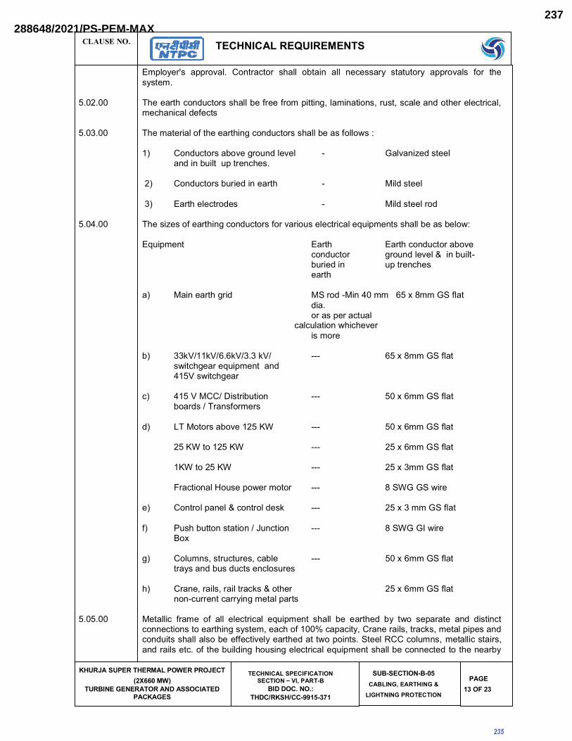
CLAUSE NO. ����������<�������
���������� ������ ����������� ���������
������������ ���������� ���������
������������>��� ����� ��� ?�@��� "�
����������� ���!���!��"##$%"'+$
��"�� ���"�"�%�������@��� �����
���� ������� �� ���
����$' �>�'
���!������ ����"�!�� �����@��� � �!!� ������ �!!� ��@������� ��������� ����"�!�� ��� � ���������
�������� [ ������ �@���@����� �!!����������������������!������������������@�!������� ����!�@���@�!����@ ���@�!�����@��
�������� [ ���������!���� ������ ����@���@����� �!!��������!!_���
�? ����@������"��������!�"�! | ��!"���^�������!����������!����������@ ���
�? ����@������������������ | ��!������!
�? ���� ��!�@����� | ��!������!���
���<���� [ ����^��������� ����@���@�������"�������!�@���@�!������������� �!!���������!_�
��������� ���� ���� �@���@�����"���@���@��� ������!�"�!�{��������!�|���������� �������@ ������
�? ��������� ����� �~����|����<����� ����������~��!����������������@���!
����������������������������������������������������������������������������������������@�!@�!�����_ �@ �"���������
�? ����������������������� ||| �� � �����~��!���_��@ ��������������� ����<�����_��@ ����
@? <���������������������� ||| �� � �����~��!����������[����������
�? �[��������"�������� ||| ����������~��!��
�������������� ||| ����������~��!��
����������� ||| ����������~��!��
��@����!�]�����_������ ||| ��~����~�_���
�? ����!�����!�{�@���!����� ||| �����������~ �!��
�? ��� �������������������@���� ||| ��~������_�����
�? �!����������@�������@��!�� ||| �� � �����~��!������������������@�����@!�����
? ����������!������!����@���{�� ��� �� � �����~��!����|@�������@������������!������
�������� ����!!�@� ������ �� �!!� �!�@���@�!� ���������� � �!!� ��� ���� ��� ��� �_� ��������� ���� ������@��@���@����������� ��������������@ ������$�@���@��������������!������@��������!�����������@�������� �!!��!���������@��"�!������ �������_��������~���!�����@!����� ����!!�@����������������!����@����� �����!����� �������!�@���@�!������������ �!!����@���@������� ���������
235
288648/2021/PS-PEM-MAX237

CLAUSE NO. ����������<�������
���������� ������ ����������� ���������
������������ ���������� ���������
������������>��� ����� ��� ?�@��� "�
����������� ���!���!��"##$%"'+$
��"�� ���"�"�%�������@��� �����
���� ������� �� ���
����$` �>�'
���� ���������@���@������������� ���������������������� � ��������������@������� �������!����������!!�@�������������!!�@�� ��� ���@���������������������!��|@���@��!���� �!!�������� �������� �����������!!�@�~ ��� ������������������!��@���@��!���� �!!�������� �������_��@ ����� ���� �!�� ��!���� � ��_���� ����"���� �"���� �!�������� ���� �� � �� �_��@ ��������@��� �!!����@���@���� ������ ����������������~��!���������������� �!����!�� !���� �� � ������ �����������!_��� ���@���_�� ��� � ���!���������� �!!� ����������@���� ��� ��!���������@���@���� �� ���� ���� ����� ��� ��"���!� !@������� �����!�� �!��� ���!���@��� ���� _�!���������������� �!!�������� �� ����!����!������!�����@��!��
�������� ��@ �@��������!����!���� ����@��!�������� �!!�������� ���������������_��!�@��������~���!���� ������ ������������ � ��������@�����_�������� ���������� � �!!� �����@��������������� ���"��� ���� � ���� ��� ��� �"��!��!�� ��@������� @���@����� � �!!� ��� ���� ��� ���"���� ������� ��!�@��������� �������
�������� }�����!���������][������������� �!!�������� ���� ��� �}������������[ �������@���� �!!�@���@��� ��}������� ��������������� ��!�@���������������!������ �@���@����
�������� }�����!� @���@����� ���� ����!!�@� @������������� � �!!� ��� ��� ����� ��� � �� �������������� ����� ��� ������ ����@���� ������� �_�� @���@���� � �!!� ��� ��� @���@���� �� � ������� ����@���@������"��� ��������!�"�!�
���#���� ����@��������_�������� �!�������������������� �!!�����!!��������!��������������@�������@��� � �!!� ��� � ��� !�� @!������ ������ @���@������ ���������� �!���� @���@����������������������������@ �@����� �!!������������_�� ������@����"��������@������
�������� ~�����!������ ���������������"�� � �!!������"�������"������� ����!��������!�"�!�� ���� �������������������"��!��!������ ���������!����������������� �@���@���
�������� ����@����� ���_���� ���������� ���� ���� !����� ���� ���_���� ����� ���� ���� @���@����� �!!� ��� �� _�!���� ������ �� ����� ����@���� � �� _�!��� � �!�� ��� �������� _�� � ���� !����@���������� �����_����� � �@�!�� @����� _�� ���������@�������\!!�_�!����@���@������ �!!�������������!�@���@���@�_�!�����
�������� ��������@�� �� � �� ����� � �!!� ��� ��� ���� � ��� � �� ��������@�� �� � �� ����"�!���� !���� � ��@���@����
�������� ���� ���� @���@���� ������� ��� ������ � �!!� ��� !���� �������� ���� ��� ��!_� ������ !�"�!���!���� � ��_���� ����@����� ��� � �� ���_����� ��@�� ��!!���� �������!� �� ��� �!�@��� "��� �������@���@���� � �!!� ��� ����� �������������� �����!�������������@�� ��!!���� � �!!� ����!�@��� ���!���������������
���<���� ���� ����@���@����������������� ��@�@������!����� �����!������ �!!� �"������������!��������@�@�����@"���
�������� \������������� �@"���������������� �!!������"��������_�������� �@���@�������� �������������@ ������������������������������@������������� ����@���@����@��������� ������@�����������!!�������������� ���"������� ����@���@���@����������������!����� ������� ��� ������@�� �!��� ����!!�@� ����@������ ��@ � ��� ����� _������ ������ ����� !������ ����!�������@���������@�@���������� �!!������������� �������
�������� ���� ����@���@�����!��� � ���� ������@!������_�!!�����@��� �!!����������������������!��_�!�������@!���������������"�!�������������������������@��"�!��
�������� ���� ������ �!!�������������������{�� �!!����@�����@������������~���<����!�@������� �!!���������������!_�������������������!�"�!�������������@�������_�����!�@������� �!!��������������� ������� �!!������������_�� ���!������@ ��@�!���������~���<���[����!������ �!!����
236
288648/2021/PS-PEM-MAX238

CLAUSE NO. ����������<�������
���������� ������ ����������� ���������
������������ ���������� ���������
������������>��� ����� ��� ?�@��� "�
����������� ���!���!��"##$%"'+$
��"�� ���"�"�%�������@��� �����
���� ������� �� ���
����$% �>�'
��"����� _�� � �!���� ������������ �!��_�� � ��@ � ���� � ����� ��� ����� �� ��@�!������������������������ ���������@�����{�_ ������������
�������� ���@��!������� �����!!�����@��������������� �@���@������������@���@�����!!���������������� � �!!� ��� @ �@����� ���� � ��������@�� ��� ���� � ������������ � �!!� ��� �������� ������@����� \!!�������������������������������� �!!���������� ������@����@���
���#���� ���� ���� @���@��� � �!!� ��� ������� ��� !����� ������� ������� � �� ���@�� �� �!�@���@�!������!!��������"�����!��������������� �����@��������!!�������� �!!����@���@���������� ���������������!����
�������� �� ���������������������� ����~������
~����������� ����������~���<�
���� ����~�����
���������@���@� <�������
~��������!����"�! \�������������������������*��?
~�!��������"��� \@���!�������������@��������
�����~���!�@����� �����������
���� ��������!������������ �@���@�� ������ ��!_� ������ !�"�!£� � _ ���� ��� @����������@ �������������@���������!������!����@������@������� �!!�������!�������������!_�� ���
����@��������� ��� �!�@���@� ��@� _�!������ _�� � ��������@�� �� ������������� ���� ������ ��@���@���
��!��� �� ��� �������� _�� � ���� !���� ��� ����� ����@���� ���� � ��� @����� _�� � ��������@���������@����������@����
~����@���������"���� | ���"�! ����� �|�����
| ��@���� ���� �|�����
������� ���� ������� �� ���[ ��
�������� ��� ����������@������������ �!! ����������@���@@����@��_�� ���������� �
�������� ��� ������@���@���� �!!��������������~�������_ ����������"�������� !�"�!������ �!!����@���@����� ��� ������!����_�� ����� ��!�@��������� ����������
�������� ��� ������ ������� � �!!� @������� �� ���� ������������� �_�� @���@����� ����� !������ ���� ��!�@�������@�������������"������_�����
�������� �\���\�}�z]\^_
�� �_�� @���@���� � �!!� ��� ��� � ��� ���� ������ �� ��� ���@��@��!�� ���� � �!!� �!!_� ������@����� ������� ��!�@�����
�� ��@ ��_��@���@���� �!!������"�����_�� �������� !�����������������"��������!�"�!� ��� ������������ ��� � �!!� ��� ����@@�����!�� �� ����������@���}�@���@������ ���� ���� ���������@����������� ��!�@������ �!!�����������!_�������������
237
288648/2021/PS-PEM-MAX239

CLAUSE NO. ����������<�������
���������� ������ ����������� ���������
������������ ���������� ���������
������������>��� ����� ��� ?�@��� "�
����������� ���!���!��"##$%"'+$
��"�� ���"�"�%�������@��� �����
���� ������� �� ���
����$� �>�'
�� \!!����������� ���_��@���@����� �!!����_�!���������
<� �_��@���@����� �!!����@!�����������������������!�����_�!!�����������������"�!���_�!����������������!�����@!���������������������"�!�
�� ��� ������ @���@��� �� ��� � �!!� ��� ��� ����@�!�� @!������ �� �����@�� �� ����~����������!@�������������!������@������� �!!������������@���@���������������������"�!�����������
�� \!!� ����!!�@� ����@������ _�� ��� �� "�@������ �� �_� ������� �� � �� @���@���� � �!!� �����������@���@������!�� ����������@�����������
�� ��� ������@���@����� �!!���������� ��� �������������������������
�� [�������!����� �!!�������������!"���^�������!�����^����������
#� ��!��������������!�� ������� �!!��������@@������
��� ]�^������������ ���!�������!�����!�����!��"���������!����� ���@�������������������� �!!��������@�����������������������!����� ��
+������ �
�������� \!!����������� ���������!����� �!!������ ����� ���������������������������!�������������� � ��@����@���� �!!������������_����������"�!�� ������������!!�� ����������������!���������� ������@���@����� ���� @������� ��� _�� ��� !���� ���� ������ ���� � �� ����� �� ���� �������� [ ������������ �!��������� �������@���@������� ����������������!������ �������������������!���� ������ � ��� @����@�� ���� � �� ����*�?� � �!�� �"�� ����� ��� ��� @���@���� ��� ���������������!����������� �!�� �"�������_��������������@!�����
������� ]_�"��� ��� � ��@����@��� ��������!�� ��������� �������� � �� ����� ����*�?�@���@����_�� ���!������������������� ��������������������������� ��@���������������������*�?��������������� ��� �������� � �� ���@���@����� �������������� � �� @����@��� � �!!� @���@�� �!!� ��@ � ������������� ���@����@���������������!�@������ ��_������� ������� ����������!��������������@����@!�����_�����������������"�������������� ����������������"�!�
������� \!!� �@@�����@�� ���� ������� ������ ��� ���� � �����@���@����� ���� ��!�"���� ���������� � �!!� ���@������������ ���������� ����� �!!������������������@!��������� ���������������@��
������< [ �� ����� ����� ������� �@�� ����"��� ��� ���� ����@��� � �!!� ��� �������� ��� �������@��� �����������������@�����}[������������������� ����_�!!���������� ������� ��������@������
� �������������� ����
�������� ��| |_]^|�\^]__��{{�|��^�j_�|}�\^]�|�\{{\�j��
�������� [���������������!��[������������������
�? |_]$��
��� ����� ������� @ ����!� ����|��� ��� @����!�"��� ����� ������ �� ��� ����� �!��� \� ���������� !���� � �� ����� ������� @ ����!� � �!!� ��� ������ "����@�!!�� ��� ��@ � ���� �� �� ����������@������������� ������������������������� _������ ����@!�������_�������� ��*�?��������� ��� @����!�"��� ����� � �!!� ��� ������ �� � �� ����� @ ����!� ���� ��@ � ���� � �!!� ���!�����"���� ����������������_�� ����������_������!�������������~���������!���������!������������� �!!�������!�������������\������������!������!!� � �����������!����_�@��� ��_������!���� �!!����� ���������!��������!�@������ �!!����������������� ��������� _������ ����@!�������_������������� ���!!_����!��������"�!��
238
288648/2021/PS-PEM-MAX240
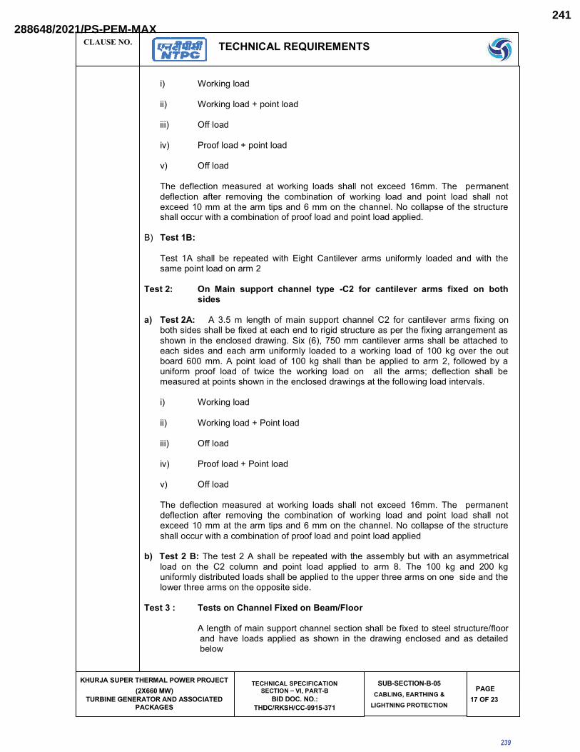
CLAUSE NO. ����������<�������
���������� ������ ����������� ���������
������������ ���������� ���������
������������>��� ����� ��� ?�@��� "�
����������� ���!���!��"##$%"'+$
��"�� ���"�"�%�������@��� �����
���� ������� �� ���
����$+ �>�'
�? �������!��
��? �������!���`������!��
���? ����!��
�"? ����!���`������!��
"? ����!��
[ �� ���!�@���� ��������� ��� _������ !���� � �!!� ��� ��@���� ������ [ �� � �������������!�@���� ������ ���"���� � �� @��������� �� _������ !��� ���� ����� !��� � �!!� �����@�������������� ���������������������� � ��@ ����!��}�@!!�������� ������@������ �!!�@@���_�� ���@���������������!������������!������!����
�? |_]$��
[���� �\� � �!!� ��� ��������� _�� � ��� �� �����!�"��� ����� ������!�� !����� ���� _�� � � ������������!����������
|_]�� �� ��j� _���\^] z����|{ ]��| "�� �\^ z��]j{|�|^ �^~_ �j�|} \� �\]�_j}|_
�� |_]��� \� ���� �� !���� � �� ����� ������� @ ����!� ��� ��� @����!�"��� ����� ������� ���� �������� �!!���������������@ �����������������@������������� ������������������������� _�� ��� � ����@!�������_�����~��� *�?�� �������@����!�"��������� �!!� �������@ ��� ����@ � ������ ���� ��@ � ����������!�� !����� �� �� _������ !��� �� ������� "��� � �� ������������ ����\� ����� !��������� ���� �!!� � ������ ���!���� ������ ��� �!!_��� ������������ ���� !��� �� �_�@�� � �� _������ !��� �� � �!!� � �� ����£� ���!�@���� � �!!� ���������������������� _������ ����@!�������_��������� ���!!_����!��������"�!��
�? �������!��
��? �������!���`������!��
���? ����!��
�"? ����!���`������!��
"? ����!��
[ �� ���!�@���� ��������� ��� _������ !���� � �!!� ��� ��@���� ������ [ �� � �������������!�@���� ������ ���"���� � �� @��������� �� _������ !��� ���� ����� !��� � �!!� �����@�������������� ���������������������� � ��@ ����!��}�@!!�������� ������@������ �!!�@@���_�� ���@���������������!������������!������!���
�� |_]��� [ �� �������\�� �!!�������������_�� � � ��������!������_�� �������������@�!�!��� �� � �� ��� @!���� ���� ����� !��� ���!���� �� ���� ��� [ �� ���� ��� ���� ���� ���������!��������������!����� �!!�������!������� ��������� ������������������������� ��!_���� ������������ ��������������
|_]'� |_]_\������|{>j�|}\��|�~!>{\\^
\�!���� ��������������@ ����!���@����� �!!����������������!�����@������!����� �"�� !���� ���!���� ��� � _�� ��� � �� ���_���� ��@!���� ���� ��� �����!�����!_
239
288648/2021/PS-PEM-MAX241

CLAUSE NO. ����������<�������
���������� ������ ����������� ���������
������������ ���������� ���������
������������>��� ����� ��� ?�@��� "�
����������� ���!���!��"##$%"'+$
��"�� ���"�"�%�������@��� �����
���� ������� �� ���
����$� �>�'
�� |_]'�� \�� !���� �������!�����@������ �!!���������!�� �������������� �!����� ����������������� !���� � �� @ ����!� ��@���� ������ ����� @!����� _�!�����!����� \� �����!��� �� ����� ��� � �!!� ��� ���!���� �� � �� @������ ����� "��� �_� ���@������ }��������������!!������� ��@��������� �!!�������!�@��
�� |_]'�� ��� �� ��@��������������!���������[�����\���_���������@�!��������!�������������� �!!��������!������!�����!������������������������� ����������� ��@������!��������������������!!������� ��@��������� �!!�������!�@��
z� |_]'�� ��� � � �� @�������� ������!��� ��� ��� [���� �\�� �� ��������@�!��� ����� !���� �!!�������!���������������������������������� ��@������!����
[ �� !��� � �!!� ��� ������!!�� ��@������� �� � �� �������� "�!��� � ��� @��� ������!����_�� ��� � @���������������� ����!!������ � � ��@���������[ ��� "�!���� �!!������@�����
|_]`� �����|{��_|^] |_]
\�������!���� ������@ ����!���������� ��@�@�����_�!!������!�����@�������������@���!� ����� �����!!�����@����������� �������������@����!�"��������� �!!� �������@ ��� �����@ ����!���� � _�� �����@!�������_����� ���@ �����������!��!���������_������!������������"���� ������������������\������!������������� �!!�� ���������!��������������!!_�������������������!������_�@��� �� _������ !��� �� � �!!� � �� ����£� ���!�@���� � �!!� ��� ��������� ��� ������� _������ ����@!�������_��������� ���!!_����!��������"�!��
j� �\^�j���\�}jj� �\^�j���\�}��\j�]�\�}
jjj� ����\�}j�� �^\\��\�}��\j�]�\�}�� ���{\�}
[ �� ���!�@���� ��������� ��� _������ !���� � �!!� ��� ��@���� ������ [ �� �������������!�@�������������"����� ��@�����������_������!������������!���� �!!������@�������������� ����������������������� ��@ ����!��}�@!!�������� ������@������ �!!�@@���_�� ���@���������������!������������!������!���
|_]% � �����|{��]_{j�z��^�z]|^j_]jz_����]|�|^���{jz��{|�
|_]_%�$@%��@%�'� \� � !���� � �� @ ����!� � ��� ��@���� ������ !��� � �!!� � �"�� ����������@����_�� �� ���_��!������������� _��������_������@!������� � !���� ���!���� ��� � �� ������� � _�� ��� ���_���� ��@!���� ���� �!��� � �!!� �������������� _�� � �!�� ������ �� ��}��� ��� }�� ���� ��� }�� }� ��_��� � ��� � ������������������ �!!��������������@ ���������������
\��������� !�������� ��������� �!!�����������������������!���_�� ��!�� �����������}��
|_]_%�$@%��@%�'� [ �� !���� � �� @ ����!� ��� ��@���� ���� ��� !��� � �!!� �"�� ����������@����_�� �� ������!������������� _��������_������@!�������� �!�������!�������� ���������� _��������_����������!���� �!!���������������_�� ��!��������������}������}�� ���� ��� }��� }� ��_��� � ��� � ���� ������������� � �!!� ��� ����� ��� ��@ � ��������������
\���������!���������������� �!!�����������������������!���_�� ����!�������������}��
240
288648/2021/PS-PEM-MAX242

CLAUSE NO. ����������<�������
���������� ������ ����������� ���������
������������ ���������� ���������
������������>��� ����� ��� ?�@��� "�
����������� ���!���!��"##$%"'+$
��"�� ���"�"�%�������@��� �����
���� ������� �� ���
����$# �>�'
|_]� �|{}��]|�^j]� |_]
\��������!�@����������������������\�����������{�<�_�!������������� �!!����@ �@��������������@������@!�������@����������@�����|�����@��@��@�����"�!������������
�������� ���!�� ������������������������� �� � ��� � ������� �!�� �"������� �������������� �~���������������������{���"��
�������� �\�]j�|!�zz|�]��z| |_]_
������� �\�]j�| |_]_
�? �����������������������@���@������������!�@��!������������� �!!����@�������������!!��������������������@"��������� �����@���@�����
�? � ���@�!� {� ���������!� @ �@�� �� �!!� ����������� ��� ���� ����"������_��������������
�@? ]�����������!�@��!��
�? � �@����������������� �@��������������^��@�@��������@��!|@ �����!����������������@���@�����{����!�@��!�����������
�������� �zz|�]��z| |_]
�? ��!"��������[���������������!�@��!�����������
�? ��!�����@ �@��
@? ���!�@������������@��!��������
�? �������@����@ �������� !���� ���@��!���������������{���"��� �!!���� �������������!�� ���� ��@ � ������� !��� � ��� � �!!� ��� ��������� ��� �� � ���� {� !����� _�� ��������!������������������!���� ��!���� ���@��!���������[ �������������!�@�������� �����|���������@ ���^��� �!!������@��������
�? ����!�����������@��!��������������������
�? [������������~������� ����!�� �!!�������� ����!������ ����!����� ����@���������!������@����!�"��������� �!!� ��� ������������������[ ��� ������ �!!�����������������<�������������
��? [�����������~������� ����!�� �!!��������_�� ����@ ����!�����@����!�"������������������� ��������������@ ����!����������@���������!���[ ��������� �!!������������������\��������������[ ��������*�?���"��� �!!�����������
���? }����!���@ ���@�������@������*���� �!!����������������!����������������������!����_�� ����!�������������}�?��[ ��������� �!!���������������������������������[ ����@������ ��� @����������� ������[���� [����� ��� ���@���@����� � ��������� ���|����������� ����� � �!!� ��� @������� ��� ��@ �@��_�!������������
�? [ ����"���@@�����@�� ������� �!!���������!�����������!�� ������@ ��������!��
241
288648/2021/PS-PEM-MAX243

CLAUSE NO. ����������<�������
���������� ������ ����������� ���������
������������ ���������� ���������
������������>��� ����� ��� ?�@��� "�
����������� ���!���!��"##$%"'+$
��"�� ���"�"�%�������@��� �����
���� ������� �� ���
������ �>�'
������� �����������
�������� [ �� �����@��� � �!!� @����� ��� � �� �!!_���� @����������� ������ ���� @ �@��� �����������!!�������� ������ ����������� � �������@��� � �!!� @�������� �!!� � ��� @ �@������� �����������@������������ ��������@������ ���!����������������������@������������@���
�������� ���{|_
�? � �@������ ���@�!�������
�? � �@���������!�������������@�������������������������������������
@? ][� @��!��� � �!!� ��� ��������� ������ *����� "!����� ��� ���� �~���#�?� ������@�����������
�? � �@����@������������!!�@������� ��@��!���
�? � �@�����@���@���������!!�@���@��������������!�"����_����������������\�������������@�������� ������!�_������!�������"���������������� �������@ ���������������!�@���@��������@���� �!!����@�������������� �������@���
�? � �@�����@���@���!����������� ��������@��!��@���@�����
�? � �@�� ��� ������ ���� � @���@����� ��� @��!�� �!������ @��!�� ������ @��!�� ��������@���������@�
? � �@�������"�������@���@��@��!��������@��������!������� ��������@���@�����
�������� ���{|]^��_!_���\^]_��}�zz|__\^j|_
�? � �@�� ��� ������ ��!"���^������������� ���� ��������@����� ������� �� � �� @��!���������������������@@��������
�? � �@�����@�����������@��!��������"���� ��������������
�? � �@�� � �� �!!�� ����@������������������_������������!�� �"����������"��� ����� ����������������
<? � �@��������� �@����������������� �@���@������@��!��������
�������� ��^]�j����}�j��]�j���^\]|z]j\�_�_]|~
�? ���� �@���������@ �@���
�? ���� ���������@����� ��@��!��������������_�!!�������|�������
���<��� ��!_����������� �����
[ ������ ���������������!����� �!!���������������������!�����}�| ����������~���~�@�����|����[�@ ��@�!�~��@���@�����~�@���|��������|�
������������[������� ��������������!������@"��������� �����@���@������ �!!������"���������@@����@��_�� ��~���<������ ���������������
���� ��������������_������� ����� �!!���������@���@������� �����!������!��������������������� ��� � �� �!����� \!!� ������ ������ @����@��� �@��� �� ����!�� � �!!� ��� �����@���@����
242
288648/2021/PS-PEM-MAX244

CLAUSE NO. ����������<�������
���������� ������ ����������� ���������
������������ ���������� ���������
������������>��� ����� ��� ?�@��� "�
����������� ���!���!��"##$%"'+$
��"�� ���"�"�%�������@��� �����
���� ������� �� ���
�����$ �>�'
���� ��� ��� �������� �_� ����!!�!� @���@����� [ �� �����@��� � �!!� ������ � � �� �����!���������� ���� @�!@�!������ ��� ���!������ ����"�!�� �����@��� � �!!� ������ �!!� ��@��������������������"�!�� ��� � ����������\!!� � ��@!������ �!!� ������� ������������� ��������������� ������������@����� �!!����������� �����������������������_�������������� �!!������"����������@ �������������� ����@�����������~������������@������������ �!!������"�������� �{�� ���� ���� ������� ���� �!�� ��� ��� ������ �_�� @���@��� @���@���� ��������~����@����������������������� ������������� �!!������"������������� ���������������������
#������ ���� �������[�� ��������[�
� �!����"�!������ ��!������ ����������������"������@�������������� ���!!_�����������������
�? \��������������@��� �!!������������������_����� ���������������\������@������!������!!_���������_�!!������ �������
�? [������������ �!!������������������� ������@�������!���������@����������������@ �� ����������������������@���������������!_�������������_�!!����_� ����������������������� ��� �����!��������������"����� �����������������!����"����_ �@ �"������ �� ���
��!�@���@����������"����!����������������� �!���������������������@�
*���!�����?�� *���������?
�������������� ���
��������������� ����
��������������� ����
�"��������� ����
�? ���@����������!����������������� �"������������������!�@���@���������@����������� !������ ���� ����"����!� �!� @���@���� �� !���� � �� ����� !������� � �� �������������������������@�����_����������������������������������!������ �!!�������!����������!����� ������������������������������������_�!!������������@������� �� �"�!@�����������������
��?� ���!� ���@�� � �!!� ��� ��"����� ��� [���������� ����� ��� �"������ �� ��@ ������������� � � [ �� ���!� ���@�� ��� [���������� ����� � �!!� ��� @���@���� _�� � [������� ���!� ���@��[ ���������� ����� �����������{� ���!� ���� �!!� ���������`�|������������@�����������[��������������� �!!�������!��������������\|�_��� [�� ���!����� �� @!���� � �� �"������ �� �[�� ~������[�~[��\[� �� ���!� !�������@����� ����� � �!!� ��� ��"����� _ ���� � �� ���!� ���@�� @ ������ � �� ����@���������������� �!!������"����������!����@����� ���!����� ��������������
<?� �����@ � ������������������ �!!������"������!!� �����������������@����������*�������?���������������������������\����������� �!!������"����������@ ������\�@�����!������������������������ �!!������"������� !���!������������� �� !������� ����������� *��� "!���?� {� ��� �������� �� _����� ��������� �� ]��������� ������� ��� � �� !������� ������������ ~���� ���� �� ����"����!� ������������ �!!����@���@������@�����!����������������� ��������
�?������!����@��� �!!������"���������!!����������������������������� �"����������@ ����������������^������� ���������!��������\�[�������������@����������� �!!������"�����_ ����� �����!����@��@ ������� ������@�������@���������� �!!��!�������"��������� ��!@������������!!��������������������������������� �!!������"����������!����@����� ���!����� ���������������
243
288648/2021/PS-PEM-MAX245

CLAUSE NO. ����������<�������
���������� ������ ����������� ���������
������������ ���������� ���������
������������>��� ����� ��� ?�@��� "�
����������� ���!���!��"##$%"'+$
��"�� ���"�"�%�������@��� �����
���� ������� �� ���
������ �>�'
��?�[ ��[�������������@����� �!!�������������*�������?�������@������� ������_�!!��[ ��]��� �������@����� �!!����������*�������?��������@����� �!!� �"��������!�������������������"��!����������@�����������������������_�� ���_�!��
�? [ �� ����������� ����_�!!�� ���� ��^���� ���� @!�����@��� ���� ����@�������!���������@��������@���� �!!������������~���<������������!���[���������
�?��]_�"��������!!���������������������!�@���@����!����� ��������!������������@ ���������!����^��� �!!������"������!!������������������@����������*�������?���������������������������\����������� �!!������"����������@ �����@ �
�? �����������������������!�@���@�!������_��@ ��������
$� ~��������~_��@ ���������� �!!������"����������@ ���������[�����!�������!!�][�������� �!!������"��������][��_��@ ������������!������!�������!!��[�������� �!!������"���������[��_��@ ���������!��
2. The following clearances shall be maintained for HT Switchboard.
a.) Front Clearance
�?�������_���~_��� | ������*���?
��?����_��_����~_��� | ������*���?
b.) Back Clearance - 1.5 M (Min.)
c.) Side Clearance������������� _�"�����"������������������������������!�����!���������������� ��������[ �����������@!�����@��� �!!�������`_��� �������!�*��@!����������������!������������!����@�?
3. The following clearances shall be maintained for LT Switchboard.
��?������!�����@�
�?�������_���~_�� | �����*���?��?����_��_����~_�� | ������������������������� ������ ���
����!����@
��?���@���!�����@��?�������!������ | �����*���?��?������!������ | �����*���?
@�?�~�����!�����@�
������������� _�"�����"������������������������������!�����!���������������� ��������[ �����������@!�����@��� �!!�����������`�_��� �������!�
����������������][�~_��@ �����@!�����@���� �!!�����!!_���_ ���"����� ��[�{�][��_��@ ��������������� ��������������
<��]��� ����][��[�~_��@ ��������������!���������
�? ��� �������@�� <�����*���?��? ��� ���������@�� <�����*���?�
244
288648/2021/PS-PEM-MAX246

CLAUSE NO. ����������<�������
���������� ������ ����������� ���������
������������ ���������� ���������
������������>��� ����� ��� ?�@��� "�
����������� ���!���!��"##$%"'+$
��"�� ���"�"�%�������@��� �����
���� ������� �� ���
�����' �>�'
��� �����"����@�!����@������ �!!������"����������][��[��_��@ ���������������@������@��!��"��!�������
�� ���!������@ ����!��"��!�
�� �[� �_��@ ��������� ��� ��� ��� ������ �������� �<��� _���� �� �<�� ����� @��!������@ �� �!!������"����� �� ������ ��@��!����]��^���!�@��!�� ������� �!!���������� ���@��!������@ ���
@?�� ��������@!����_���������@���������������� �����������
�? ��� ���!������ �"���� ����� �������� �� ����� ��� �!��� _�� � ��� �!!���� � ����� ������������^��@���@����� �!!������"�����
�? [ ��@��!����������������������_��@ ��������� �!!����������������*�������?���"�����
245
288648/2021/PS-PEM-MAX247

246
288648/2021/PS-PEM-MAX248

���������� ����������������� ���������
������������ ���������� �������������������� ���!���!��"##$%"'+$
����� ��
SUB–SECTION – B-6
� �� �������� �����
247
(AS PER APPLICABILITY OF SCOPE DEFINED IN SECTION IA & STANDARD ELECTRICAL SCOPE BETWEEN BHEL
AND VENDOR IN SECTION IB)
288648/2021/PS-PEM-MAX249

�������� ����������<�������
���������� ������ ����������� ���������
������������ ���������� ���������
������������>��� ����� ��� ?�@��� "�
����������� ���!���!��"##$%"'+$
���� ����"��� �� ��������
�����
����$ �>��
$������ �������������[!���� ���>���?����������
[ ����^���������������� �!!����������������@����������@ �������!� !���@���@�������������� ��"������� ��@���� ��� "������ !���� @���@����� ��!�� ��"�!� ���� �!����� ����!���������������������@�
\�� ��� ��� ���@��@��!�� � �� ������� � �!!� ��"���� ����������� ����!���� �� ����� ���� ������������!������� �� � ��� � � ���!���� �� ����!�� �� ����� ����!����� � �!!� ��� �� _��� �������^�� � ��������������!������������\������@�@ ����"������@����@�!��_��@ ���� ��������@������ �!!������"����������@������������"����� ��!������������������������ �������������������
������� �|_j���\�_j}|^�]j\�_�
������� j�j��\�� �\�^}_
�? ����� ��\���������"��¤� *������ �� ����������@��?� �� *����@���@�����_����@��?�_ ����"�!������!�����@������_�����@�����������@���@����������������!_�
����*���"�@�?���@������<�����!�������������������� ���@��������!�������������������������������!���!����@������ �������@�
����@���@�������_�����@������[������� �!!����@�����������������~�������
�? [ �� ���!!�� ��!�@���� ������ �������� ��� ~_��@ ������������ \���� ���������@��� �!!���@!��������$��������"���� ��@�!@�!�����"�!����
@? ��� ����� !��� �� �� ��\� *�������?� � �!!� ��� @��������� �� ��@ � ��@���� �� ������_��@ ������_�� ���@��������������������������@��������� ���������~���
�? �������������������!"�� � �������\���� � �!!��������"��������������� �$��� � �����!���\�!���@���@��� ����� ������������ � !���������!"��� �������@���@����
�? ��!������@����� � �!!� ��� @���@���� ������!����� ����� _ �@ � � �!!� ��� ���� � ��� ������$���!�����������������
�? �~��@���������������$��������������� �!!����@����������������� ���� ���!���� �!!����������!����"�����������~��~_��@ ������
�? [ �� !���� ��� ��@ ���@�!� ����!����� �������� � �!!� ��� ���� ��� ����!����� �������������������� ��@��������� �����@ ��_��@ ��������������������������� �!!����������� ������ �����$� �� ����$� �������������������� ����� � ���� � �!!� ��� ������ �� @����� � ���������� !��� ����@���� �� ��� �������� � ��@ � �� � �� ��"�� ������ � �!!� �����@����!�^����
? [ �� ��^���� �� ����� �������@�� ������ � �!!� ��� ��� �@@������ �� � �� ��� �������� [ ���������@�� ����� � �!!� �"�� ���� �� �� � ��@����� �� ����� ~��"�@�� ~_��@ ����� ���@�������������!��������!�@�������������
�? ��������!���� *[��{�~�������?�����~��"�@�����!��������@ ���� ��������� �!!� �"�������$� ������������ �� �!!� � ��� ������� ��@ � ��� ����� ��� � �!!� �"�� �����$�������������
������� ���\�]�^j]|^j�
[ ���_��@ ������@��������!��� �����_���@�������������!�����@�������������@������!����_��@ ������ �� �����^�� ~_��@ ����� ��� !������� [ �� �_� ��@����� �� � �� ��!��� � �!!� ���@���@������������@� � ���!���������!������������������
248
288648/2021/PS-PEM-MAX250

�������� ����������<�������
���������� ������ ����������� ���������
������������ ���������� ���������
������������>��� ����� ��� ?�@��� "�
����������� ���!���!��"##$%"'+$
���� ����"��� �� ��������
�����
����� �>��
������� ��^|z���zj]���}>�]�^|�|��j^|~|�]_
\!!����~_��@ ������ �!!������"�����_�� ������� �������� �����!���������@������ ��� ��!�"����@!������ ����|\���[�@ ��@�!�~��@���@�����
���<��� ]��}�^}j��]j\�
��� � �!!� ��� ���������� �� �"�� �!!� ��� ~_��@ ������ ��� � �� ������� �!���� ���� �� ����!��������@���������������������!���������������������������������"��_�
���� �!!�����������������!!_������������^�������[������!�}��������@�����!!�������!������������������@���@�����������������@��
������� �{��]z\�]^\{z��{|��]|^z\��|z]j\�_
����!� @��!�� �����@���@����� ���_���� �_��@ ������ ���� ����������� ���� �!!���� �������_��@ ������ ���� ���� �������!� ����� �� ��� ������ ��������� ���� ���_���� "������
*�? ~��������@���!�@��!����^���� �!!�����������
*�? ���!����^������������@�� ���������!�@������ �!!��������������
*@?�����@���@����������������[�����������������!��� �!!������_�@������������ ��^�������� ���
*�? ~��������@���!�@��!���� �!!������������@������������������
*�? ~��������@���!�@��!���� �!!����!�����������*�������@���@�!���� ������?������������������~_��@ ��������� ��~_��@ �����������~�
������� ������� ������
������� \!!������������ �!!��������!!���@��!��_�� �� ������������������
*��? \��!�@��!���������~��������
*��? ��������!�@���@����\@��
*@�? ��������!�@���@������!��
������� ����������@��!�����_�� ������ ������ ������"���������������!!����@���^���������������@ ���� ����� ������ � ��~�\��� �������� ��@�� _�!!� �!�� ��� @��������� ��� ��� �������� ��������@������"�!�����������������������~���������������@ �@������ ��@����@���� �!!�@!���!������@����� ���������������������� ������ � � ��@�����!���������!�� �"�������� � ��������!���_�� � �������������������� ����!�����������������@��������
������� \!!� ����������� ���@���@������ ���� @���� �� ���@��@�� ��������� �� ������ � �!!� ��� � �� !�������������� ��@!�������!!����!�@��!�����@��!� �����������������"������������!�� ��������� ������ �� � � ���������������������� ���@������@��!�@�����_���� � ������@���@���������� ���*�~� @����� ~��������� ��@�?� ��������� �� ������� � �� ������ � �!!� ���"��!�� \!!� _��� � �!!� ���@������������������ ���!!_����@������������������
�~��� �!������������|����������������������!��
�~���#< ��������!�����@��!������_������"!�������� ��������@!������������
�~����� \�����!�@���@����������
249
288648/2021/PS-PEM-MAX251

�������� ����������<�������
���������� ������ ����������� ���������
������������ ���������� ���������
������������>��� ����� ��� ?�@��� "�
����������� ���!���!��"##$%"'+$
���� ����"��� �� ��������
�����
����' �>��
�~����<� �!�@���@�!�����@�����������������
�~��������#<� � �������������@������"����������@!���������!_�"!�����~_��@ �������������!�����
�~��������#<�|� \����@��@������������� ���������������
�~������ �������}��@���!����
�~�����# ]��������!"�������
�~������ ��������[����������
�~���������|��#<�|<|�
����@������������������������"!�����������@��������������\�������������
�~����<� ���������@��@��������� ����
�~������ ���������@��@����������!!������������������@����~_��@ ����
�~������ �!�����[����������
�~������ ���������@��@�����@!����������������!�@���@�!�����������
�~������ �!�@���@�!���!��������_��������������@����
�~�������#<� \��|������ ~_��@ ���� ���� ������ ���@���@����� ���� ������ ���@���@������� ����� @��������� ������ ��� "!������ ��� ��@������� ������ \�� ������������
�~�������#<�|����������|��#<�|�
������!�����������������~_��@ �������������!���������"!�����������@��������������
�~������ ���� ��\!������� ��� \!������� �!!�������!�@���@�!���������
�~������ ���������@��@����� �� ��������������������!�
�~�������#<�|�|�������|��#<�|�|�
����_��@ �������������!����������!�@���������"�@��������_��@ �����!������
�~����������������<�#|���
�_��!�����~_��@ �����{�����!����� ������!���
�~������ ~����@���!���
�~��������������������������#
]������������������
�~��������*<������? ���������@��@�������!�@����������!!������������������@�����_��@ ���������@���!������
250
288648/2021/PS-PEM-MAX252

�������� ����������<�������
���������� ������ ����������� ���������
������������ ���������� ���������
������������>��� ����� ��� ?�@��� "�
����������� ���!���!��"##$%"'+$
���� ����"��� �� ��������
�����
����` �>��
�~������� ~��@���@�����������������������������
���������� �!�@���@�!���!���
���������� ������@��������_�����������������������������
�~������� ���������������������������������������������@�������@���@�������������������������!�
�~������� ~��@���@�������@���!�����������������_��@ �������������!���������"!����������@�������������\��
�������#<�|�|� [������!��!@����������� @���@���
�~������*����? �!���!!����_�������~���!�~ ���������~�����
'������ �������������� ��
������� �\�|^���{�
������� \��~�~[��
�? �!���������������������������������������������������������� <�����` ��$���� �����<�_������!��!������ ��
�? ������@� ���������������������������������������� ���]^�`�| �$
�? ��������"������� *���"!���{��������@�?
��$����!�������
<? ��!����"�! �� �\*��~?
������� ���~�~[��
�? ~�������!���� �<� � ����|������������ ��
�? ��!����"�! �� �\
������� ��}[����~���������[\��
�? [����{�@!�����@�!���@��@����������� �<� �������� ����
�? ~������@ ���������� �<� �������� ����
�? ����@���!�����!� ��� ��\��}�����!��!��!������ ��
<? ~��@�� ������{�!�� ���� �<� ��\��}�����!��!��!������ ��
251
288648/2021/PS-PEM-MAX253

�������� ����������<�������
���������� ������ ����������� ���������
������������ ���������� ���������
������������>��� ����� ��� ?�@��� "�
����������� ���!���!��"##$%"'+$
���� ����"��� �� ��������
�����
����% �>��
������� ��������� �
��_��^��]j��
�? ������������������������������������������� \�������������������������������������������
�? ~ ���������������_ ���
�?�����������������@��� ������������������������� �� �\*��~?���������@������������������
�?������������������@��� �����@��"�� @������� �� ���\*��~?� ��� � �� ����� @!������������
�? ������@��������_ ���
�?�����������������@���� ��� �\*��\�?�
�?������������������@��� �����@��"�� @������� �� ��� �\*��\�?����!���������� ����
<? �����������!����
�?����_��@ ����������\��������
��������
����~!��"������!����*����<?
������� ������ �������
�? [��� ������������������������������������� \��� ������ ������� @ ������ �����������������
�? ������������������������������������������������������������������ �|� ���|��|� ���|��
�? ~�������@�!������������� �� �\*��~?
<? ~ ���@��@���������� ��� �\*��\�?�
�? ~ ������@�������������@������
�? \��������� �� �\*��~?
�? ���������� \�������~�������#<�
�? ~ ��������_�� ����� �� �\*��~?�������
�? }��������@���@�� <� }�� `� <� }�� ��� �����~��������@�
���<��� �� ��
�? \@@���@��@!��� �������������������������������������������������� ���
252
288648/2021/PS-PEM-MAX254

�������� ����������<�������
���������� ������ ����������� ���������
������������ ���������� ���������
������������>��� ����� ��� ?�@��� "�
����������� ���!���!��"##$%"'+$
���� ����"��� �� ��������
�����
����� �>��
�? ���� ����� �_��� �������@�� _�� ������ �����"!����
��� ���*���?
������� ��^^|�] ^��_�\^~|^_
�? [��� ����� ������ ���� ������� �� }�!��������
�? �!�����@!���������������@� ����������]
�? �!����������!���� ����������
<? ������~�@������������� ��\
�? \@@���@��@!����{�������
�? ������@���� ��������\�
�~��!���������
�? ���������� @!�����������\�*���?
@!���� ������ ��\� *���?� ��� ������������@��������~����������
�? �����������~�@�������@���*�~?��������������[
�
�? ~ ��������_�� �����
�? �� �[� \��@������ _�� � @��@�����������
�� �\*��~?��������@
�? �� �[� \��@������ � _�� ��������@������������
�����@��"��@����������� �\*��~?����� �������@!�����������
�? ������@�_�� ������
�? ���[��\��@������_�� �@��@����������� ��� �\*��\�?�
�? �� �[� \��@������ _�� � ��������@������������������
�����@��"�� @������� �� ����\*��\�?��������������� ����
������� ����� ����"������ ��@�������� �� [���
�? [���� }�|~���������
253
288648/2021/PS-PEM-MAX255

�������� ����������<�������
���������� ������ ����������� ���������
������������ ���������� ���������
������������>��� ����� ��� ?�@��� "�
����������� ���!���!��"##$%"'+$
���� ����"��� �� ��������
�����
����+ �>��
�? ���������� �_����������@��_�� �������"!���� ������
�? ������@���� ���@���_�� ������@������ �� �\*��~?
<? ���������������@�@�������_�� ����� ��� �\*��\�?�
������� ����� �������� [���
�? [���� ����[�������
�? ����������!�����"!���� �����
�? ������@�� � ���@���_�� ������@������ ���\*��~?
<? ���������������@�@�������_�� ����� ����\*��\�?�
�? �_����������@��_�� ������"!���� ����"
�? ����!���_�� ������"!���� ���
�? ����!����� �!����
������� ?�� ��� ���>�����
�? [��� ����������
�? �!��������� <��������������!�����[
�? ��� ����������@��� �|�
<? \@@���@���!��� ���
�������������������@��������~����������
�? �������!�������@�� ���@���������������������@�
�? �!����������!���� ����������
�? ���� ������� �_��� �������@��_�� ������"!����
������
���#��� ���>��
�? �!������!���� �����!��
254
288648/2021/PS-PEM-MAX256

�������� ����������<�������
���������� ������ ����������� ���������
������������ ���������� ���������
������������>��� ����� ��� ?�@��� "�
����������� ���!���!��"##$%"'+$
���� ����"��� �� ��������
�����
����� �>��
�? ����������@���@��� �� �\�*���?����\��@���� �� �\�������@���
������� ��� �� ��
�? [���� \����������!�@����������@
�? ���!�������������� \��� �� �~�������#<�� ������ ��"�����!��\�<����~�������#<�������"�����!�����"��
������� �|{��_
�? �_����������@��_�� ������"!���� ��� ��� ��� �� ��@�� �� ���� ��� ��� ������
������� ��� ��� ���>�����
�? [��� ����������������
�? �!��������� <��� �� ��� � _�� � ����� ` �$� ��������������$
�? �!����������!���� �!���|����������
<? ���� ������� �_��� �������@�� _�� ������"!����
��� ��
�? ������ ��� � \��������������!�@�����
������� ���� ��� ���>����� !������� ���>�����
�? [����{������� �������������� ��\*��!�����[�?������\*�������?*��� �����[�?
�? �!��������� <���<����� `�| �$� ����� ��� �����������$
�? �!����������!���� ����������
<? ���� ������� �_��� �������@�� _�� ������"!����
������
�? ��@!���������@��� ��|<�
255
288648/2021/PS-PEM-MAX257

�������� ����������<�������
���������� ������ ����������� ���������
������������ ���������� ���������
������������>��� ����� ��� ?�@��� "�
����������� ���!���!��"##$%"'+$
���� ����"��� �� ��������
�����
����# �>��
���<��� ��������
�? ���������������@���
�? ����� �|��\�*�[���@�����?
�? �������������@� �� ]^
@? ������� <|����\�*��}�����@��!��?
�? �"���@������ [������@��� ��� ���� @���������������� � �!!� ��� @����!�� ��_�� ��������� ������� �������[� ��@��@����������\�����������������������@���
�? \@@���@� ���
�? �!�����[������@���
�? ����� ��������������������������������������������������� ��� �� ��� ]^ *��� \�? � ��� � ���� � ���*�����?
�? ������ <|����\�*��}�����@��!��?
@? \@@���@� ���
������� ����
�? ������"!���� <���
�? ����������!�����!�"�! �#��
�? �������!�������{ ~��"�@��~�������������@���@��� �� �\
<? �������������@���@��� ��� �\
�? ���!�^�����@������ \
������� ����
������"!���� <���
����������!�����!�"�! �#��
�������!�������{ ~��"�@��~�������������@���@��� ����\
�������������@���@��� �����\
���!�^�����@������ \
256
288648/2021/PS-PEM-MAX258

2X660 MW KHURJA STPP
TECHNICAL SPECIFICATION FOR ELEVATOR
SPECIFIC TECHNICAL REQUIREMENT -ELECTRICAL
SPECIFICATION No: PE-TS-475-502-A001 VOL IIB SECTION IB REV. 00 APR 2021
STANDARD MANUFACTURING QUALITY PLAN
FOR MOTORS (UPTO 55 KW)
257
288648/2021/PS-PEM-MAX259

258
288648/2021/PS-PEM-MAX260

259
288648/2021/PS-PEM-MAX261

�\����~�]���������\[ \}}���������
�}�[�\���}� ��� [� �����~�
�\����~�����*�]����������}���? ���\��~ �\���~� � �\[]�\���}�
[�}[\[�����\������}�[]
260
288648/2021/PS-PEM-MAX262

2X660 MW KHURJA STPP
TECHNICAL SPECIFICATION FOR ELEVATOR
DATASHEET A
SPECIFICATION No: PE-TS-475-502-A001 SECTION IC REV. 00 APR 2021
SECTION – IC
DATASHEET A
261
288648/2021/PS-PEM-MAX263
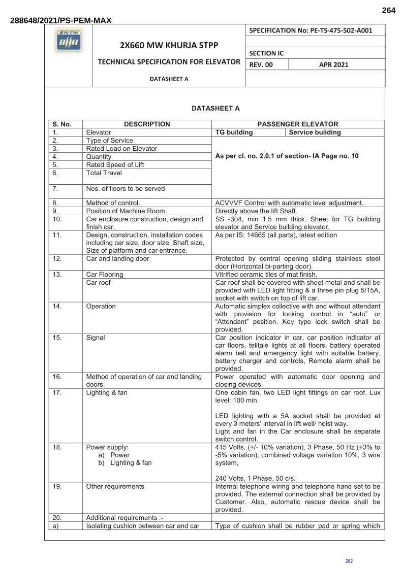
2X660 MW KHURJA STPP
TECHNICAL SPECIFICATION FOR ELEVATOR
DATASHEET A
SPECIFICATION No: PE-TS-475-502-A001 SECTION IC REV. 00 APR 2021
DATASHEET A
S. No. DESCRIPTION PASSENGER ELEVATOR 1. Elevator TG building Service building 2. Type of Service
As per cl. no. 2.0.1 of section- IA Page no. 10
3. Rated Load on Elevator 4. Quantity 5. Rated Speed of Lift 6. Total Travel
7. Nos. of floors to be served
8. Method of control. ACVVVF Control with automatic level adjustment. 9. Position of Machine Room Directly above the lift Shaft. 10. Car enclosure construction, design and
finish car. SS -304, min 1.5 mm thick. Sheet for TG building elevator and Service building elevator.
11. Design, construction, installation codes including car size, door size, Shaft size, Size of platform and car entrance.
As per IS: 14665 (all parts), latest edition
12. Car and landing door Protected by central opening sliding stainless steel door (Horizontal bi-parting door).
13. Car Flooring Vitrified ceramic tiles of mat finish. Car roof Car roof shall be covered with sheet metal and shall be
provided with LED light fitting & a three pin plug 5/15A, socket with switch on top of lift car.
14. Operation Automatic simplex collective with and without attendant with provision for locking control in “auto” or “Attendant” position. Key type lock switch shall be provided.
15. Signal Car position indicator in car, car position indicator at car floors, telltale lights at all floors, battery operated alarm bell and emergency light with suitable battery, battery charger and controls, Remote alarm shall be provided.
16. Method of operation of car and landing doors.
Power operated with automatic door opening and closing devices.
17. Lighting & fan One cabin fan, two LED light fittings on car roof. Lux level: 100 min. LED lighting with a 5A socket shall be provided at every 3 meters’ interval in lift well/ hoist way. Light and fan in the Car enclosure shall be separate switch control.
18. Power supply: a) Power b) Lighting & fan
415 Volts, (+/- 10% variation), 3 Phase, 50 Hz (+3% to -5% variation), combined voltage variation 10%, 3 wire system, 240 Volts, 1 Phase, 50 c/s.
19. Other requirements
Internal telephone wiring and telephone hand set to be provided. The external connection shall be provided by Customer. Also, automatic rescue device shall be provided.
20. Additional requirements :- a) Isolating cushion between car and car Type of cushion shall be rubber pad or spring which
262
288648/2021/PS-PEM-MAX264

2X660 MW KHURJA STPP
TECHNICAL SPECIFICATION FOR ELEVATOR
DATASHEET A
SPECIFICATION No: PE-TS-475-502-A001 SECTION IC REV. 00 APR 2021
frame shall be provided. shall be as per manufacturer’s standard. b) Three pin plug with socket on car top 5/15A, 3 pin plug socket with switch on top of lift car
and inside shaft to take care maintenance requirement. c) Car frame Material and type of
construction Steel and bolted construction
d) Landing Door Fire rated for min. 2 hours. e) Type of operation - Automatic.
- The door of car and landing shall be interlocked in such a way opening and closing of two doors shall be simultaneous and the doors will open when the lift is in lading zone.
f) Door hanger tracks along with accessories shall be provided.
Required
g) Safety shoes complete with accessories shall be provided.
Yes
h) Safety device for door operation shall be provided.
Full length Infrared light curtain along with pressure limiter as an extra mechanical safety is required.
i) Handrails on three sides of car Mirror finish stainless steel j) False ceiling SS 304. k) Emergency stop switch Yes. l) Braille switch Yes. 21. Control and operation
(a)Type of control Simplex / duplex (b)Type of drive Variable voltage variable frequency drive
22. Car operating panel Provided (a)Type of construction Partial Height car operating panel (COP), Removable
type from Car with SS face plate. (b)Push Buttons Luminous push buttons with IP 54
23. Car position indicator Provided. (a)Type of construction As per manufacturer’s standard (b)Type of display 7 segment LED display.
24. Push button station and call registered tell-tale lights at each landing
Provided in each landing
(a)Type of construction Box type with SS face plate (b)Push Buttons Luminous push buttons with IP 54
25. Apron / Facia Plate provided as per IS 14665
Yes (To be provided by supplier)
26. Emergency Light Required. 27. Terminal buffers, their types and number
of buffers Spring buffers shall be Provided as per IS 14665.
28. Load plate As per manufacturer’s standard / as applicable 29. Counter weights frame Fabricated Steel Construction 30. Counter weight fillers Cast Iron 31. Number of Limit Switches As per requirement a) Location Bottom & top terminal
b) Type Electromechanical
c) Operation Cam Operated 32. Controller and type Selective Collective Controller with variable voltage
variable frequency drive and Microprocessor based software controlled logic system
263
288648/2021/PS-PEM-MAX265

2X660 MW KHURJA STPP
TECHNICAL SPECIFICATION FOR ELEVATOR
DATASHEET A
SPECIFICATION No: PE-TS-475-502-A001 SECTION IC REV. 00 APR 2021
33. Reverse phase relay and other protective devices
Required
34. Car Safety & Governor a) Stopping distance As per IS:14665 b) Type and mode of operation of Over speed Governor device
Centrifugal action
c) Tripping speed and design code conforming to
As per IS 14665 (latest addition).
d) Location At machine room. 35. Motor details
(a) Type 3 phase AC squirrel Cage Induction motor (b) Type of Duty Lift Duty (c) Motor Duty S4 /S5 (d) Duty Cycle of Motor 60% (e) Applicable standard IS:325 f) No. Of Starts Per Hour Elevator Motor shall be suitable for minimum of 150
Starts per hour. g)Direction of rotation Both Clockwise & Anticlockwise h)Class of Insulation F, temp rise limited to class B.
Motor shall be provided with thermal class 130 (B) or better insulation.
i)Method of Starting AC Variable Voltage Variable Frequency Drive 36. Door Motor
a) Equipment driven by Motor Door b) Direction of rotation Both Clockwise & Anticlockwise
c) Type of enclosures IP54
37. Metallic Wire Mesh between Car & Counter Weight
Required
38. Fire Man Switch Required
39. Sound Reducing Material Isolation Rubber / other arrangement in the Machine shall be provided
40. Automatic Rescue Device (Battery Drive)
Provided
41. Trailing cables FRLS type. 42. Design seismic coefficient
(an additional information for elevator building only)
According to IS 1893 - 1977
43. Split Air condition in machine room As per Machine room area (not less than 2T Capacity). 44. 1/2 Kg CO2/suitable type Fire
extinguisher with fixing arrangement. Provided.
264
40%
288648/2021/PS-PEM-MAX266

2X660 MW KHURJA STPP
TECHNICAL SPECIFICATION FOR ELEVATOR
STANDARD TECHNICAL REQUIREMENT -ELECTRICAL
SPECIFICATION No: PE-TS-475-502-A001 SECTION IIA REV. 00 APR 2021
SECTION – IIA
STANDARD TECHNICAL REQUIREMENT-ELECTRICAL
265
288648/2021/PS-PEM-MAX267

SPEC. NO. PE-TS-475-502-A001
2X660 MW KHURJA STPP SECTION - IIA TECHNICAL SPECIFICATION FOR ELEVATOR STANDARD TECHNICAL REQUIREMENT -ELECTRICAL
PE
M-6
66
6-0
The Supplier shall have a permanent representative office with a trained and skilled support staff, in the country where the goods are delivered, in order to prove his commitment for local support and to provide a channel for communication.
The engineers employed by the Supplier’s regional office shall be certified by the
Manufacturer and provide start-up service including physical inspection of the drive, connected wiring and final adjustments, to ensure that the AC Drive meets the required performance.
The Supplier shall be able to give basic drives training to the Customer’s engineers,
preferably on the site. The training shall, as a minimum, include system concepts and basic troubleshooting.
2.0 Basic requirements for the AC Drives 2.1 General requirements The AC Drive shall comply with National (country of origin) and International
standards and the recommendations for electrical industrial control devices (IEC, EN, UL, NFC, and VDE).
The AC Drive shall be of the most modern design, yet user friendly and be simple to
install commission and maintain. The AC Drive shall be able to start and control the speed of a standard squirrel cage induction AC motor. The AC Drives shall be: CE marked, conforming to European Low Voltage (73/23/CEE and 93/68/CEE) and EMC (89/336/CEE) Directives, UL/CSA marked according to UL 508C.
The AC Drives have to be built to comply with the IEC standards. The AC Drive shall be a digitally controlled drive, using, at least, the Pulse Width
Modulation (PWM) with flux vector control open loop (for travel) and closed loop (for hoist). It shall have diodes / thyristors in rectifier and IGBT’s in the inverter section in their entire power range, and it shall have the following minimum specifications.
Rated Input Voltages 380V to 480V (-10% to +10% variation), three-phase
Rated Input Frequency 50Hz +3 % to - 5% Output Voltage 0 – Input voltage, three-phase Output Frequency Range 0 to 400 Hz Acceleration / Deceleration Time 0.01 – 999s, adjustable, linear, with S,
with U or customised shapes
266
288648/2021/PS-PEM-MAX268

SPEC. NO. PE-TS-475-502-A001
2X660 MW KHURJA STPP SECTION - IIA TECHNICAL SPECIFICATION FOR ELEVATOR STANDARD TECHNICAL REQUIREMENT -ELECTRICAL
PE
M-6
66
6-0
Overload capability (Constant Torque) 150% of nominal current for 1min. Operating ambient Temperature -10°C up to 50°C(shall be de-rated
suitably if not rated at 50°C) Storage ambient Temperature -25°C up to 70 °C Maximum operating altitude 1000 m without de-rating, 1000…3000
(shall be de-rated suitably) Max. Relative Humidity 95 %, without condensation and dripping
water. Main Protections Over current, short circuit between phase,
short circuit between phase and ground, input phase loss, output phase loss, motor overload, over speed, over voltage, under voltage, drive over temperature
The AC Drive shall be able to give a 100 % output current continuously in the above
specified conditions. In order to ensure that the drive can provide the required output current in the specified ambient conditions, the Manufacturer shall inform the required de-rating, if the ambient temperature given in the project-specific specification is higher than rated ambient of the drive or if the installation altitude is more than 1000 m above the sea level. The de-rating factor shall be specified so that neither the lifetime of the AC Drive nor the unit’s performance, overload capability included, nor the reliability of the AC Drive shall suffer.
Suitable encoder shall be provided for main hoist motion.
3.0 User interface 3.1 General The user interface shall be identical throughout the power range and type to avoid
confusion amongst the users and need for training in several different units. 3.2 Inputs and outputs A. At least, the following standard Inputs and Outputs shall be provided, to be used in
interface with the control system: Analogue Inputs : 1 x Programmable differential voltage input + 10V, 1 x Programmable current input 0(4) - 20mA 1 x Programmable voltage input 0 – 10V Analogue Output : 1 x Programmable analogue outputs 0(4) - 20mA or 0 –
10V Logic inputs : 6 x Programmable logic Inputs isolated from the mains
267
288648/2021/PS-PEM-MAX269

SPEC. NO. PE-TS-475-502-A001
2X660 MW KHURJA STPP SECTION - IIA TECHNICAL SPECIFICATION FOR ELEVATOR STANDARD TECHNICAL REQUIREMENT -ELECTRICAL
PE
M-6
66
6-0
Relay Outputs : 2 x Programmable Digital outputs with a changeover dry contact
All the control terminals shall be clearly marked. B. At least, it shall be possible to assigned the following functions to the I/Os:
Analogue input Analogue outputs Speed reference Summing reference
Motor current Motor frequency Motor torque Motor power
Logic input Relay or logic outputs (open collector) Forward Reverse Jog Preset speeds Reference switching Ramp switching Parameter sets selection Fast stop Freewheel stop + speed - speed External fault
Ready Drive running High speed attained Drive fault Frequency threshold attained Motor thermal state attained Torque or current limitation attained Brake control
3.4 Programming terminal A. The AC drive shall have a keypad /display for programming and controlling purposes.
An IP54 or IP65 remote mounting shall be possible at a distance of 10m. B. Password protection shall be provided to avoid unauthorized tampering with the set
parameters. C. The programming terminal shall be able to display the commercial reference of the
AC drive and of the options, the software version, the serial number D. Direct keypad entry shall be provided to observe the following actual parameters. Any
one of the following parameters or actual values shall be selected to be always displayed:
i) Input Voltage ii) Input Frequency iii) Output Frequency
268
288648/2021/PS-PEM-MAX270

SPEC. NO. PE-TS-475-502-A001
2X660 MW KHURJA STPP SECTION - IIA TECHNICAL SPECIFICATION FOR ELEVATOR STANDARD TECHNICAL REQUIREMENT -ELECTRICAL
PE
M-6
66
6-0
iv) Output Power v) Output Current vi) Motor Speed The following parameters shall always be displayed during normal operation:- i) Drive Status The following drive control functions at least shall be available from the keypad:- i) Run ii) Stop iii) Local / Remote selection. iv) Forward/Reverse (if function enabled) v) Accelerate vi) Decelerate vii) Parameter setting 3.5 Application programming The AC Drive shall be designed for both simple and the most complicated
applications, yet it shall be user friendly. It shall be possible to reset the parameter settings back to the original factory settings through the keypad.
3.6 PC Tools The AC Drive Supplier shall have Windows based PC software available for
monitoring and controlling the AC Drives, and the software shall be offered as an option. The software shall be supplied with the necessary hardware and a provision for connecting a PC with the AC Drives. It shall be possible to set and modify parameters, control the drive, read actual values and make trend analysis using the software.
4.0 Software features A. Restart In the event of a fault trip due to over voltage, over current or loss of analogue signal,
the AC DRIVE shall be programmable to attempt an automatic restart. For safety reasons, the maximum number of attempts shall be within a selectable time. If the fault does not clear after the attempts, the drive shall lock out.
B. Brake logic control
269
288648/2021/PS-PEM-MAX271

SPEC. NO. PE-TS-475-502-A001
2X660 MW KHURJA STPP SECTION - IIA TECHNICAL SPECIFICATION FOR ELEVATOR STANDARD TECHNICAL REQUIREMENT -ELECTRICAL
PE
M-6
66
6-0
The AC Drive shall have a built-in function to control a mechanical brake in order to move the load in a smooth and safe way. The brake logic control shall be adapted to the different movements: hoisting, travel, orientation.
5. Preferred makes: As per List of makes –ANNEXURE-I
270
288648/2021/PS-PEM-MAX272

2X660 MW KHURJA STPP
TECHNICAL SPECIFICATION FOR ELEVATOR
SPECIFICATION No: PE-TS-475-502-A001 SECTION III REV. 00 APR 2021
SECTION III
1. DOCUMENTS TO BE SUBMITTED ALONG WITH BID 2. PRE-BID CLARIFICATION SCHEDULE 3. COMPLIANCE CUM CONFIRMATION CERTIFICATE 4. ELECTRICAL LOAD LIST
271
288648/2021/PS-PEM-MAX273

2X660 MW KHURJA STPP
TECHNICAL SPECIFICATION FOR ELEVATOR
SPECIFICATION No: PE-TS-475-502-A001 SECTION III REV. 00 APR 2021
DRAWINGS / DOCUMENTS TO BE SUBMITTED WITH THE BID Bidder shall submit the following drawings / documents along with their bid:
a) Deviation schedule with reference to specific clauses of the specification along with reason for
such deviation in the ‘Deviation Schedule’ (Cost of withdrawal) format as attached in GCC.
b) Un-priced copy of price format indicating quoted/ not quoted against each row/column
c) Copy of pre-bid clarifications/ amendment/ corrigendum issued by BHEL, if any, duly signed &
stamped
d) Signed/ Stamped copy of Compliance cum Confirmation Certificate
OFFER WILL BE CONSIDERED AS INCOMPLETE IN ABSENCE OF ANY OF ABOVE
DOCUMENTS. DOCUMENT OTHER THAN ABOVE, IF ANY, SUBMITTED WITH THE OFFER
WILL NOT FORM PART OF CONTRACT AND WILL NOT BE CONSIDERED FOR BID
EVALUATION.
272
288648/2021/PS-PEM-MAX274

2X660 MW KHURJA STPP
TECHNICAL SPECIFICATION FOR ELEVATOR
SPECIFICATION No: PE-TS-475-502-A001 SECTION III REV. 00 APR 2021
PRE-BID CLARIFICATION SCHEDULE
S. NO. SECTION/CLAUSE/PAGE NO. STATEMENT OF THE REFERRED CLAUSE
CLARIFICATION REQUIRED
The bidder hereby clarifies that above mentioned are the only clarifications required on the technical
specification for the subject package.
Signature: ______________
Name: _________________
Designation: ____________
Company: ______________
Date: __________________
Company Seal
273
288648/2021/PS-PEM-MAX275

2X660 MW KHURJA STPP
TECHNICAL SPECIFICATION FOR ELEVATOR
SPECIFICATION No: PE-TS-475-502-A001 SECTION III REV. 00 APR 2021
COMPLIANCE CUM CONFIRMATION CERTIFICATE The bidder shall confirm compliance with following by signing / stamping this compliance certificate (every sheet) and furnish same with the offer.
a) The scope of supply, technical details, construction features, design parameters etc. shall be as per technical specification & there are no exclusions, other than those mentioned under “exclusion and those resolved as per ‘Schedule of Deviations’, with regard to same.
b) There are no other deviations w.r.t. specifications other than those furnished in the
‘Schedule of Deviations’. Any other deviation, stated or implied, taken elsewhere in the offer stands withdrawn unless specifically brought out in the ‘Schedule of Deviations’
c) Bidder shall submit QP in the event of order based on the guidelines given in the
specification & QP enclosed therein. QP will be subject to BHEL / CUSTOMER approval & customer hold points for inspection / testing shall be marked in the QP at the contract stage. Inspection / testing shall be witnessed as per same apart from review of various test certificates/ Inspection records etc. This is within the contracted price without any extra implications to BHEL after award of the contract.
d) All drawings/ data-sheets / calculations etc. submitted along with the offer shall not be taken
cognizance off. e) The offered materials shall be either equivalent or superior to those specified in the
specification & shall meet the specified / intended duty requirements. In case the material specified in the specifications is not compatible for intended duty requirements then same shall be resolved by the bidder with BHEL during the pre-bid discussions, otherwise BHEL / Customer’s decision shall be binding on the bidder whenever the deficiency is pointed out.
For components where materials are not specified, same shall be suitable for intended duty, all materials shall be subject to approval in the event of order.
f) The commissioning spares shall be supplied on ‘As Required Basis’ & prices for same
included in the base price itself.
g) All sub vendors shall be subject to BHEL / CUSTOMER approval in the event of order.
h) Guarantee for plant/equipment shall be as per relevant clause of GCC / SCC / Other Commercial Terms & Conditions
i) In the event of order, all the material required for completing the job at site shall be supplied by the bidder within the ordered price even if the same are additional to approved billing break up, approved drawing or approved Bill of quantities within the scope of work as tender specification. This clause will apply in case during site commissioning, additional requirements emerges due to customer and / or consultant’s comments. No extra claims shall be put on this account
j) Schedule of drawings submissions, comment incorporations & approval shall be as
stipulated in the specifications. The successful bidder shall depute his design personnel to BHEL’s / Customer’s / Consultant’s office for across the table resolution of issues and to get documents approved in the stipulated time.
274
288648/2021/PS-PEM-MAX276

2X660 MW KHURJA STPP
TECHNICAL SPECIFICATION FOR ELEVATOR
SPECIFICATION No: PE-TS-475-502-A001 SECTION III REV. 00 APR 2021
k) As built drawings shall be submitted as and when required during the project execution.
l) The bidder has not tempered with this compliance cum confirmation certificate and if at
any stage any tempering in the signed copy of this document is noticed then same shall be treated as breach of contract and suitable actions shall be taken against the bidder.
m) Successful bidder shall furnish detailed erection manual for each of the equipment
supplied under this contract at least 3 months before the scheduled erection of the concerned equipment / component or along with supply of concerned equipment / component whichever is earlier.
n) Document approval by customer under Approval category or information category shall
not absolve the vendor of their contractual obligations of completing the work as per specification requirement. Any deviation from specified requirement shall be reported by the vendor in writing and require written approval. Unless any change in specified requirement has been brought out by the vendor during detail engineering in writing while submitting the document to customer for approval, approved document (with implicit deviation) will not be cited as a reason for not following the specification requirement.
o) In case vendor submits revised drawing after approval of the corresponding drawing, any
delay in approval of revised drawing shall be to vendor’s account and shall not be used as a reason for extension in contract completion.
275
288648/2021/PS-PEM-MAX277
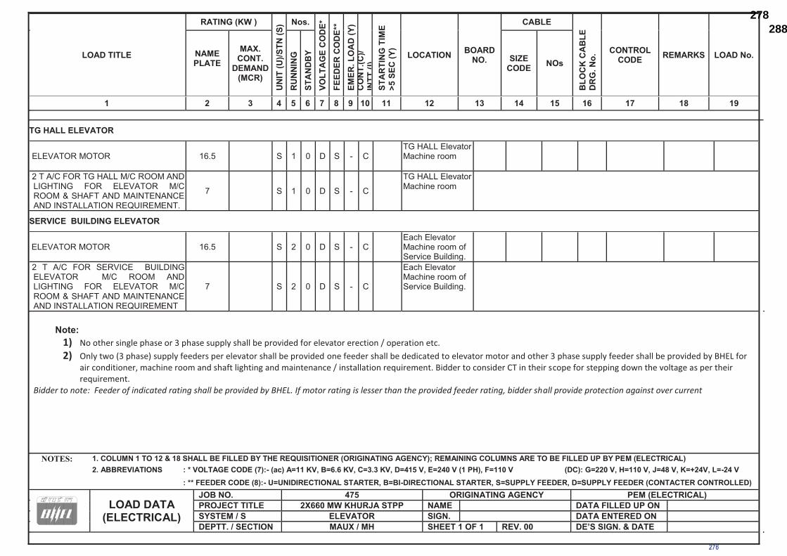
LOAD TITLE
RATING (KW )
UN
IT (U
)/STN
(S) Nos.
VOLT
AG
E C
OD
E*
FEED
ER C
OD
E**
EMER
. LO
AD
(Y)
CO
NT.
(C)/
INTT
(I)ST
AR
TIN
G T
IME
>5 S
EC (Y
)
LOCATION BOARD NO.
CABLE
BLO
CK
CA
BLE
D
RG
. No.
CONTROL CODE REMARKS LOAD No. NAME
PLATE
MAX. CONT.
DEMAND (MCR)
RU
NN
ING
ST
AN
DB
Y SIZE CODE NOs
1 2 3 4 5 6 7 8 9 10 11 12 13 14 15 16 17 18 19
NOTES: 1. COLUMN 1 TO 12 & 18 SHALL BE FILLED BY THE REQUISITIONER (ORIGINATING AGENCY); REMAINING COLUMNS ARE TO BE FILLED UP BY PEM (ELECTRICAL) 2. ABBREVIATIONS : * VOLTAGE CODE (7):- (ac) A=11 KV, B=6.6 KV, C=3.3 KV, D=415 V, E=240 V (1 PH), F=110 V (DC): G=220 V, H=110 V, J=48 V, K=+24V, L=-24 V
: ** FEEDER CODE (8):- U=UNIDIRECTIONAL STARTER, B=BI-DIRECTIONAL STARTER, S=SUPPLY FEEDER, D=SUPPLY FEEDER (CONTACTER CONTROLLED)
LOAD DATA
(ELECTRICAL)
JOB NO. 475 ORIGINATING AGENCY PEM (ELECTRICAL) PROJECT TITLE 2X660 MW KHURJA STPP NAME DATA FILLED UP ON SYSTEM / S ELEVATOR SIGN. DATA ENTERED ON DEPTT. / SECTION MAUX / MH SHEET 1 OF 1 REV. 00 DE’S SIGN. & DATE
TG HALL ELEVATOR
ELEVATOR MOTOR 16.5 S 1 0 D S - C TG HALL Elevator Machine room
2 T A/C FOR TG HALL M/C ROOM AND LIGHTING FOR ELEVATOR M/C ROOM & SHAFT AND MAINTENANCE AND INSTALLATION REQUIREMENT.
7 S 1 0 D S - C
TG HALL Elevator Machine room
SERVICE BUILDING ELEVATOR
ELEVATOR MOTOR 16.5 S 2 0 D S - C Each Elevator Machine room of Service Building.
2 T A/C FOR SERVICE BUILDING ELEVATOR M/C ROOM AND LIGHTING FOR ELEVATOR M/C ROOM & SHAFT AND MAINTENANCE AND INSTALLATION REQUIREMENT
7 S 2 0 D S - C
Each Elevator Machine room of Service Building.
Note:
1) No other single phase or 3 phase supply shall be provided for elevator erection / operation etc. 2) Only two (3 phase) supply feeders per elevator shall be provided one feeder shall be dedicated to elevator motor and other 3 phase supply feeder shall be provided by BHEL for
air conditioner, machine room and shaft lighting and maintenance / installation requirement. Bidder to consider CT in their scope for stepping down the voltage as per their requirement.
Bidder to note: Feeder of indicated rating shall be provided by BHEL. If motor rating is lesser than the provided feeder rating, bidder shall provide protection against over current
276
288648/2021/PS-PEM-MAX278
Related Documents